
Caller ID (CID) Algorithm User's Guide
71
Caller ID (CID) Algorithm User’s Guide www.spiritDSP.com/CST Literature Number: SPRU632 March 2003
Transcript of Caller ID (CID) Algorithm User's Guide

Caller ID (CID) AlgorithmUser’s Guide
www.spiritDSP.com/CST
Literature Number: SPRU632March 2003

IMPORTANT NOTICE
Texas Instruments Incorporated and its subsidiaries (TI) reserve the right to make corrections, modifications,enhancements, improvements, and other changes to its products and services at any time and to discontinueany product or service without notice. Customers should obtain the latest relevant information before placingorders and should verify that such information is current and complete. All products are sold subject to TI’s termsand conditions of sale supplied at the time of order acknowledgment.
TI warrants performance of its hardware products to the specifications applicable at the time of sale inaccordance with TI’s standard warranty. Testing and other quality control techniques are used to the extent TIdeems necessary to support this warranty. Except where mandated by government requirements, testing of allparameters of each product is not necessarily performed.
TI assumes no liability for applications assistance or customer product design. Customers are responsible fortheir products and applications using TI components. To minimize the risks associated with customer productsand applications, customers should provide adequate design and operating safeguards.
TI does not warrant or represent that any license, either express or implied, is granted under any TI patent right,copyright, mask work right, or other TI intellectual property right relating to any combination, machine, or processin which TI products or services are used. Information published by TI regarding third–party products or servicesdoes not constitute a license from TI to use such products or services or a warranty or endorsement thereof.Use of such information may require a license from a third party under the patents or other intellectual propertyof the third party, or a license from TI under the patents or other intellectual property of TI.
Reproduction of information in TI data books or data sheets is permissible only if reproduction is withoutalteration and is accompanied by all associated warranties, conditions, limitations, and notices. Reproductionof this information with alteration is an unfair and deceptive business practice. TI is not responsible or liable forsuch altered documentation.
Resale of TI products or services with statements different from or beyond the parameters stated by TI for thatproduct or service voids all express and any implied warranties for the associated TI product or service andis an unfair and deceptive business practice. TI is not responsible or liable for any such statements.
Mailing Address:
Texas InstrumentsPost Office Box 655303Dallas, Texas 75265
Copyright 2003, Texas Instruments Incorporated

iiiRead This First
Preface
Read This First
About This Manual
The following abbreviations are used in this document:
AS Alerting Signal
CallerID, CID Caller Identification Delivery (service)
CAS Customer premises equipment Alerting Signal
CLIP Calling Line Identification Presentation
CLIR Calling Line Identification Restriction
CPE Customer premises equipment. Also known as TE(Terminal Equipment)
DT-AS Dual Tone-Alerting Signal.
DTMF Dual Tone Multi-Frequency
FSK Frequency-Shift Keying
LE Local Exchange
MDMF Multiple data message format. Also known as “CallSetup”
PBX Private Branch Exchange
PLMN Public Land Mobile Network
PSTN Public Switched Telephone Network
SDMF Single data message format. Is used in old telephonenetworks
TAS TE Alerting Signal
TE Terminal Equipment
TE-ACK TE Acknowledgement Signal
VMWI Visual Message Waiting Indication
XDAIS TMS320 DSP Algorithm Standard

Related Documentation From Texas Instruments
iv
Related Documentation From Texas Instruments
Using the TMS320 DSP Algorithm Standard in a Static DSP System(SPRA577)
TMS320 DSP Algorithm Standard Rules and Guidelines (SPRU352)
TMS320 DSP Algorithm Standard API Reference (SPRU360)
Technical Overview of eXpressDSP-Compliant Algorithms for DSP SoftwareProducers (SPRA579)
The TMS320 DSP Algorithm Standard (SPRA581)
Achieving Zero Overhead with the TMS320 DSP Algorithm Standard IALG In-terface (SPRA716)
Related Documentation
Public Switched Telephone Network (PSTN); Calling Line Identification Pre-sentation (CLIP) supplementary service; Service description, ETS 300 648,March 1997, DE/NA-010023
Public Switched Telephone Network (PSTN); Calling Line Identification Re-striction (CLIR) supplementary service; Service description, ETS 300 649,March 1997, DE/NA-010024
Public Switched Telephone Network (PSTN); Subscriber line protocol over thelocal loop for display (and related) services; Part 1: On hook data transmission,ETS 300 659-1, DE/SPS-03034-1
Public Switched Telephone Network (PSTN); Subscriber line protocol over thelocal loop for display (and related) services; Part 2: Off-hook data transmis-sion, ETS 300 659-2, September 1997, DE/SPS-03034-2
Public Switched Telephone Network (PSTN); Protocol over the local loop fordisplay and related services
Terminal Equipment requirements; Part 1: Off-line data transmission, ETS 300778-1, September 1997, DE/ATA-005062-1
Public Switched Telephone Network (PSTN); Protocol over the local loop fordisplay and related services; Terminal Equipment requirements; Part 2: On-line data transmission, ETS 300 778-2, September 1997, DE/ATA-005062-2
CCITT Recommendation V.23 (1988): “600/1 200-baud modem standardizedfor use in the general switched telephone network”.

Trademarks
vRead This First
Calling Line Identification Service, British Telecommunication plc, SIN227, Is-sue 03.
Calling Line Identification Service, TE Equipment Requirement, British Tele-communication plc, SIN242, Issue 02, Nov., 1996.
Trademarks
TMS320� is a trademark of Texas Instruments.
SPIRIT CORP� is a tradmark of Spirit Corp.
All other trademarks are the property of their respective owners.
Software Copyright
CST Software Copyright 2003, SPIRIT Technologies, Inc.

If You Need Assistance
vi
If You Need Assistance . . .
� World-Wide Web SitesTI Online http://www.ti.comSemiconductor Product Information Center (PIC) http://www.ti.com/sc/docs/products/index.htmDSP Solutions http://www.ti.com/dsp320 Hotline On-line� http://www.ti.com/sc/docs/dsps/support.htmMicrocontroller Home Page http://www.ti.com/sc/microNetworking Home Page http://www.ti.com/sc/docs/network/nbuhomex.htmMilitary Memory Products Home Page http://www.ti.com/sc/docs/military/product/memory/mem_1.htm
� North America, South America, Central AmericaProduct Information Center (PIC) (972) 644-5580TI Literature Response Center U.S.A. (800) 477-8924Software Registration/Upgrades (972) 293-5050 Fax: (972) 293-5967U.S.A. Factory Repair/Hardware Upgrades (281) 274-2285U.S. Technical Training Organization (972) 644-5580Microcontroller Hotline (281) 274-2370 Fax: (281) 274-4203 Email: [email protected] Modem BBS (281) 274-3700 8-N-1DSP Hotline Email: [email protected] Internet BBS via anonymous ftp to ftp://ftp.ti.com/pub/tms320bbsNetworking Hotline Fax: (281) 274-4027
Email: [email protected]
� Europe, Middle East, AfricaEuropean Product Information Center (EPIC) Hotlines:
Multi-Language Support +33 1 30 70 11 69 Fax: +33 1 30 70 10 32Email: [email protected]
Deutsch +49 8161 80 33 11 or +33 1 30 70 11 68English +33 1 30 70 11 65Francais +33 1 30 70 11 64Italiano +33 1 30 70 11 67
EPIC Modem BBS +33 1 30 70 11 99European Factory Repair +33 4 93 22 25 40Europe Customer Training Helpline Fax: +49 81 61 80 40 10
� Asia-PacificLiterature Response Center +852 2 956 7288 Fax: +852 2 956 2200Hong Kong DSP Hotline +852 2 956 7268 Fax: +852 2 956 1002Korea DSP Hotline +82 2 551 2804 Fax: +82 2 551 2828Korea DSP Modem BBS +82 2 551 2914Singapore DSP Hotline Fax: +65 390 7179Taiwan DSP Hotline +886 2 377 1450 Fax: +886 2 377 2718Taiwan DSP Modem BBS +886 2 376 2592Taiwan DSP Internet BBS via anonymous ftp to ftp://dsp.ee.tit.edu.tw/pub/TI/
� JapanProduct Information Center +0120-81-0026 (in Japan) Fax: +0120-81-0036 (in Japan)
+03-3457-0972 or (INTL) 813-3457-0972 Fax: +03-3457-1259 or (INTL) 813-3457-1259DSP Hotline +03-3769-8735 or (INTL) 813-3769-8735 Fax: +03-3457-7071 or (INTL) 813-3457-7071DSP BBS via Nifty-Serve Type “Go TIASP”

viiRead This First
� DocumentationWhen making suggestions or reporting errors in documentation, please include the following information that is on the titlepage: the full title of the book, the publication date, and the literature number.
Mail: Texas Instruments Incorporated Email: [email protected] Email: [email protected] Documentation Services, MS 702P.O. Box 1443Houston, Texas 77251-1443
Note: When calling a Literature Response Center to order documentation, please specify the literature number of thebook.
For product price & availability questions, please contact your local ProductInformation Center, or see www.ti.com/sc/support http://www.ti.com/sc/sup-port for details.
For additional CST technical support, see the TI CST Home Page(www.ti.com/telephonyclientside) or the TI Semiconductor KnowledgeBaseHome Page (www.ti.com/sc/knowledgebase).
If you have any problems with the Client Side Telephony software, please, readfirst the list of Frequently Asked Questions at http://www.spiritDSP.com/CST.
You can also visit this web site to obtain the latest updates of CST software &documentation.
If You Need Assistance

Contents
ix
Contents
1 Introduction to Caller ID (CID) Algorithms 1-1. . . . . . . . . . . . . . . . . . . . . . . . . . . . . . . . . . . . . . . . . This chapter is a brief explanation of Caller ID (CID) algorithms and their use with theTMS320C5400 platform.
1.1 Introduction 1-2. . . . . . . . . . . . . . . . . . . . . . . . . . . . . . . . . . . . . . . . . . . . . . . . . . . . . . . . . . . . . . . 1.2 XDAOS Basics 1-4. . . . . . . . . . . . . . . . . . . . . . . . . . . . . . . . . . . . . . . . . . . . . . . . . . . . . . . . . . . .
1.2.1 Application/Framework 1-4. . . . . . . . . . . . . . . . . . . . . . . . . . . . . . . . . . . . . . . . . . . . . . 1.2.2 Interface 1-5. . . . . . . . . . . . . . . . . . . . . . . . . . . . . . . . . . . . . . . . . . . . . . . . . . . . . . . . . . . 1.2.3 Application Development 1-6. . . . . . . . . . . . . . . . . . . . . . . . . . . . . . . . . . . . . . . . . . . . .
1.3 Limitations 1-9. . . . . . . . . . . . . . . . . . . . . . . . . . . . . . . . . . . . . . . . . . . . . . . . . . . . . . . . . . . . . . . .
2 Caller ID Integration 2-1. . . . . . . . . . . . . . . . . . . . . . . . . . . . . . . . . . . . . . . . . . . . . . . . . . . . . . . . . . . . . This chapter provides descriptions, diagrams, and examples explaining the integration of CIDalgorithms and describes the various states of CID integration.
2.1 Overview 2-2. . . . . . . . . . . . . . . . . . . . . . . . . . . . . . . . . . . . . . . . . . . . . . . . . . . . . . . . . . . . . . . . . 2.2 Integration Flow 2-4. . . . . . . . . . . . . . . . . . . . . . . . . . . . . . . . . . . . . . . . . . . . . . . . . . . . . . . . . . . 2.3 International Support 2-7. . . . . . . . . . . . . . . . . . . . . . . . . . . . . . . . . . . . . . . . . . . . . . . . . . . . . . .
2.3.1 CPE Side Operation 2-7. . . . . . . . . . . . . . . . . . . . . . . . . . . . . . . . . . . . . . . . . . . . . . . . . 2.3.2 Local Exchange Side Operation 2-10. . . . . . . . . . . . . . . . . . . . . . . . . . . . . . . . . . . . . . 2.3.3 DTMF-Based CallerID Reception and Transmission 2-12. . . . . . . . . . . . . . . . . . . .
2.4 Specific Issues 2-13. . . . . . . . . . . . . . . . . . . . . . . . . . . . . . . . . . . . . . . . . . . . . . . . . . . . . . . . . . . 2.4.1 Link-Time Configurable Options 2-13. . . . . . . . . . . . . . . . . . . . . . . . . . . . . . . . . . . . . . 2.4.2 Detection Delays 2-14. . . . . . . . . . . . . . . . . . . . . . . . . . . . . . . . . . . . . . . . . . . . . . . . . .
2.5 Integration by Using the CIDWRAPPER Class 2-15. . . . . . . . . . . . . . . . . . . . . . . . . . . . . . . . 2.6 Example of a Call Sequence 2-16. . . . . . . . . . . . . . . . . . . . . . . . . . . . . . . . . . . . . . . . . . . . . . . .
3 CallerID (CID) API Descriptions 3-1. . . . . . . . . . . . . . . . . . . . . . . . . . . . . . . . . . . . . . . . . . . . . . . . . . This chapter provides the user with a clear understanding of Caller ID (CID) algorithms and theirimplementation with the TMS320 DSP Algorithm Standard interface (XDAIS).
3.1 Standard Interface Structures 3-2. . . . . . . . . . . . . . . . . . . . . . . . . . . . . . . . . . . . . . . . . . . . . . . . 3.1.1 Instance Creation Parameters 3-3. . . . . . . . . . . . . . . . . . . . . . . . . . . . . . . . . . . . . . . . 3.1.2 Link-Time Configurable Options 3-4. . . . . . . . . . . . . . . . . . . . . . . . . . . . . . . . . . . . . . . 3.1.3 SAS Signal Parameters 3-4. . . . . . . . . . . . . . . . . . . . . . . . . . . . . . . . . . . . . . . . . . . . . . 3.1.4 DT-AS Detector Parameters 3-5. . . . . . . . . . . . . . . . . . . . . . . . . . . . . . . . . . . . . . . . . . 3.1.5 TE-ACK Signal Parameters 3-5. . . . . . . . . . . . . . . . . . . . . . . . . . . . . . . . . . . . . . . . . . 3.1.6 FSK Carrier Detector Parameters 3-6. . . . . . . . . . . . . . . . . . . . . . . . . . . . . . . . . . . . .

Contents
x
3.1.7 Bit Synchronizer Parameters 3-6. . . . . . . . . . . . . . . . . . . . . . . . . . . . . . . . . . . . . . . . . 3.1.8 DT-AS Generator Parameters 3-7. . . . . . . . . . . . . . . . . . . . . . . . . . . . . . . . . . . . . . . . 3.1.9 TE-ACK Detector Parameters 3-7. . . . . . . . . . . . . . . . . . . . . . . . . . . . . . . . . . . . . . . . 3.1.10 FSK Generator Parameters 3-8. . . . . . . . . . . . . . . . . . . . . . . . . . . . . . . . . . . . . . . . . . 3.1.11 DTMF Decoder Parameters 3-9. . . . . . . . . . . . . . . . . . . . . . . . . . . . . . . . . . . . . . . . . . 3.1.12 DTMF Encoder Parameters 3-9. . . . . . . . . . . . . . . . . . . . . . . . . . . . . . . . . . . . . . . . . . 3.1.13 Russian Caller ID Parameters 3-10. . . . . . . . . . . . . . . . . . . . . . . . . . . . . . . . . . . . . . .
3.2 Standard Interface Functions 3-11. . . . . . . . . . . . . . . . . . . . . . . . . . . . . . . . . . . . . . . . . . . . . . . 3.2.1 Algorithm Initialization 3-11. . . . . . . . . . . . . . . . . . . . . . . . . . . . . . . . . . . . . . . . . . . . . . 3.2.2 Algorithm Deletion 3-11. . . . . . . . . . . . . . . . . . . . . . . . . . . . . . . . . . . . . . . . . . . . . . . . . 3.2.3 Instance Creation 3-12. . . . . . . . . . . . . . . . . . . . . . . . . . . . . . . . . . . . . . . . . . . . . . . . . . 3.2.4 Instance Deletion 3-12. . . . . . . . . . . . . . . . . . . . . . . . . . . . . . . . . . . . . . . . . . . . . . . . . .
3.3 Vendor-Specific Interface Structures 3-13. . . . . . . . . . . . . . . . . . . . . . . . . . . . . . . . . . . . . . . . . 3.3.1 Caller ID States 3-14. . . . . . . . . . . . . . . . . . . . . . . . . . . . . . . . . . . . . . . . . . . . . . . . . . . . 3.3.2 Data-Link Level Message 3-15. . . . . . . . . . . . . . . . . . . . . . . . . . . . . . . . . . . . . . . . . . . 3.3.3 Presentation Level Message 3-16. . . . . . . . . . . . . . . . . . . . . . . . . . . . . . . . . . . . . . . . . 3.3.4 Caller ID Error Codes 3-20. . . . . . . . . . . . . . . . . . . . . . . . . . . . . . . . . . . . . . . . . . . . . . .
3.4 Vendor-Specific Interface Functions 3-21. . . . . . . . . . . . . . . . . . . . . . . . . . . . . . . . . . . . . . . . .3.4.1 Configure the State-of-CID Software 3-21. . . . . . . . . . . . . . . . . . . . . . . . . . . . . . . . . . 3.4.2 Get Current State of CID 3-22. . . . . . . . . . . . . . . . . . . . . . . . . . . . . . . . . . . . . . . . . . . . 3.4.3 Get Error Code 3-23. . . . . . . . . . . . . . . . . . . . . . . . . . . . . . . . . . . . . . . . . . . . . . . . . . . . 3.4.4 Process Samples to be Received 3-23. . . . . . . . . . . . . . . . . . . . . . . . . . . . . . . . . . . . 3.4.5 Process Samples to be Transmitted 3-24. . . . . . . . . . . . . . . . . . . . . . . . . . . . . . . . . . 3.4.6 Parse Data-link and Presentation Level Messages 3-24. . . . . . . . . . . . . . . . . . . . . .
3.5 The CIDWRAPPER Class API Reference 3-26. . . . . . . . . . . . . . . . . . . . . . . . . . . . . . . . . . . . 3.5.1 Caller ID Wrapper State 3-26. . . . . . . . . . . . . . . . . . . . . . . . . . . . . . . . . . . . . . . . . . . . . 3.5.2 Caller ID Wrapper Sequence 3-26. . . . . . . . . . . . . . . . . . . . . . . . . . . . . . . . . . . . . . . . 3.5.3 Caller ID Wrapper Functions 3-27. . . . . . . . . . . . . . . . . . . . . . . . . . . . . . . . . . . . . . . . .
A Test Environment A-1. . . . . . . . . . . . . . . . . . . . . . . . . . . . . . . . . . . . . . . . . . . . . . . . . . . . . . . . . . . . . . . A.1 Description of Directory Tree A-2. . . . . . . . . . . . . . . . . . . . . . . . . . . . . . . . . . . . . . . . . . . . . . . .
A.1.1 Test Vectors Format A-2. . . . . . . . . . . . . . . . . . . . . . . . . . . . . . . . . . . . . . . . . . . . . . . . . A.1.2 Test Project A-3. . . . . . . . . . . . . . . . . . . . . . . . . . . . . . . . . . . . . . . . . . . . . . . . . . . . . . . .

Figures
xiContents
Figures
1-1 XDAIS System Layers 1-4. . . . . . . . . . . . . . . . . . . . . . . . . . . . . . . . . . . . . . . . . . . . . . . . . . . . . . . . 1-2 XDAIS Layers Interaction Diagram 1-5. . . . . . . . . . . . . . . . . . . . . . . . . . . . . . . . . . . . . . . . . . . . . . 1-3 Module Instance Lifetime 1-7. . . . . . . . . . . . . . . . . . . . . . . . . . . . . . . . . . . . . . . . . . . . . . . . . . . . . . 2-1 Typical CallerID Flowchart During Off Hook (on call waiting) 2-5. . . . . . . . . . . . . . . . . . . . . . . . 2-2 Typical CallerID Flowchart During On Hook 2-6. . . . . . . . . . . . . . . . . . . . . . . . . . . . . . . . . . . . . .
Tables
xii
Tables
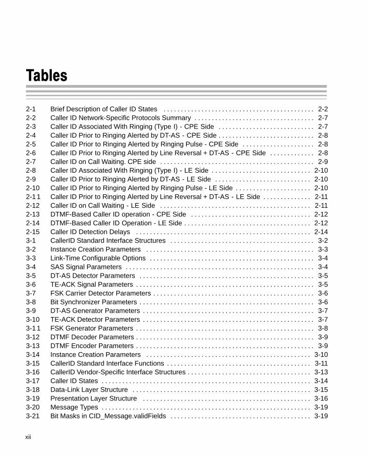
2-1 Brief Description of Caller ID States 2-2. . . . . . . . . . . . . . . . . . . . . . . . . . . . . . . . . . . . . . . . . . . . 2-2 Caller ID Network-Specific Protocols Summary 2-7. . . . . . . . . . . . . . . . . . . . . . . . . . . . . . . . . . . 2-3 Caller ID Associated With Ringing (Type I) - CPE Side 2-7. . . . . . . . . . . . . . . . . . . . . . . . . . . . 2-4 Caller ID Prior to Ringing Alerted by DT-AS - CPE Side 2-8. . . . . . . . . . . . . . . . . . . . . . . . . . . . 2-5 Caller ID Prior to Ringing Alerted by Ringing Pulse - CPE Side 2-8. . . . . . . . . . . . . . . . . . . . . 2-6 Caller ID Prior to Ringing Alerted by Line Reversal + DT-AS - CPE Side 2-8. . . . . . . . . . . . . 2-7 Caller ID on Call Waiting. CPE side 2-9. . . . . . . . . . . . . . . . . . . . . . . . . . . . . . . . . . . . . . . . . . . . . 2-8 Caller ID Associated With Ringing (Type I) - LE Side 2-10. . . . . . . . . . . . . . . . . . . . . . . . . . . . . 2-9 Caller ID Prior to Ringing Alerted by DT-AS - LE Side 2-10. . . . . . . . . . . . . . . . . . . . . . . . . . . . 2-10 Caller ID Prior to Ringing Alerted by Ringing Pulse - LE Side 2-10. . . . . . . . . . . . . . . . . . . . . . 2-11 Caller ID Prior to Ringing Alerted by Line Reversal + DT-AS - LE Side 2-11. . . . . . . . . . . . . . 2-12 Caller ID on Call Waiting - LE Side 2-11. . . . . . . . . . . . . . . . . . . . . . . . . . . . . . . . . . . . . . . . . . . . 2-13 DTMF-Based Caller ID operation - CPE Side 2-12. . . . . . . . . . . . . . . . . . . . . . . . . . . . . . . . . . . 2-14 DTMF-Based Caller ID Operation - LE Side 2-12. . . . . . . . . . . . . . . . . . . . . . . . . . . . . . . . . . . . . 2-15 Caller ID Detection Delays 2-14. . . . . . . . . . . . . . . . . . . . . . . . . . . . . . . . . . . . . . . . . . . . . . . . . . . 3-1 CallerID Standard Interface Structures 3-2. . . . . . . . . . . . . . . . . . . . . . . . . . . . . . . . . . . . . . . . . . 3-2 Instance Creation Parameters 3-3. . . . . . . . . . . . . . . . . . . . . . . . . . . . . . . . . . . . . . . . . . . . . . . . . 3-3 Link-Time Configurable Options 3-4. . . . . . . . . . . . . . . . . . . . . . . . . . . . . . . . . . . . . . . . . . . . . . . . 3-4 SAS Signal Parameters 3-4. . . . . . . . . . . . . . . . . . . . . . . . . . . . . . . . . . . . . . . . . . . . . . . . . . . . . . . 3-5 DT-AS Detector Parameters 3-5. . . . . . . . . . . . . . . . . . . . . . . . . . . . . . . . . . . . . . . . . . . . . . . . . . . 3-6 TE-ACK Signal Parameters 3-5. . . . . . . . . . . . . . . . . . . . . . . . . . . . . . . . . . . . . . . . . . . . . . . . . . . . 3-7 FSK Carrier Detector Parameters 3-6. . . . . . . . . . . . . . . . . . . . . . . . . . . . . . . . . . . . . . . . . . . . . . . 3-8 Bit Synchronizer Parameters 3-6. . . . . . . . . . . . . . . . . . . . . . . . . . . . . . . . . . . . . . . . . . . . . . . . . . . 3-9 DT-AS Generator Parameters 3-7. . . . . . . . . . . . . . . . . . . . . . . . . . . . . . . . . . . . . . . . . . . . . . . . . . 3-10 TE-ACK Detector Parameters 3-7. . . . . . . . . . . . . . . . . . . . . . . . . . . . . . . . . . . . . . . . . . . . . . . . . . 3-11 FSK Generator Parameters 3-8. . . . . . . . . . . . . . . . . . . . . . . . . . . . . . . . . . . . . . . . . . . . . . . . . . . . 3-12 DTMF Decoder Parameters 3-9. . . . . . . . . . . . . . . . . . . . . . . . . . . . . . . . . . . . . . . . . . . . . . . . . . . . 3-13 DTMF Encoder Parameters 3-9. . . . . . . . . . . . . . . . . . . . . . . . . . . . . . . . . . . . . . . . . . . . . . . . . . . . 3-14 Instance Creation Parameters 3-10. . . . . . . . . . . . . . . . . . . . . . . . . . . . . . . . . . . . . . . . . . . . . . . . 3-15 CallerID Standard Interface Functions 3-11. . . . . . . . . . . . . . . . . . . . . . . . . . . . . . . . . . . . . . . . . . 3-16 CallerID Vendor-Specific Interface Structures 3-13. . . . . . . . . . . . . . . . . . . . . . . . . . . . . . . . . . . . 3-17 Caller ID States 3-14. . . . . . . . . . . . . . . . . . . . . . . . . . . . . . . . . . . . . . . . . . . . . . . . . . . . . . . . . . . . . 3-18 Data-Link Layer Structure 3-15. . . . . . . . . . . . . . . . . . . . . . . . . . . . . . . . . . . . . . . . . . . . . . . . . . . . 3-19 Presentation Layer Structure 3-16. . . . . . . . . . . . . . . . . . . . . . . . . . . . . . . . . . . . . . . . . . . . . . . . . 3-20 Message Types 3-19. . . . . . . . . . . . . . . . . . . . . . . . . . . . . . . . . . . . . . . . . . . . . . . . . . . . . . . . . . . . . 3-21 Bit Masks in CID_Message.validFields 3-19. . . . . . . . . . . . . . . . . . . . . . . . . . . . . . . . . . . . . . . . .

Tables
xiiiContents
3-22 Caller ID Error Codes 3-20. . . . . . . . . . . . . . . . . . . . . . . . . . . . . . . . . . . . . . . . . . . . . . . . . . . . . . . . 3-23 CallerID-Specific Interface Functions 3-21. . . . . . . . . . . . . . . . . . . . . . . . . . . . . . . . . . . . . . . . . . . 3-24 CIDWRAPPER Class API Reference Table Summary 3-26. . . . . . . . . . . . . . . . . . . . . . . . . . . . 3-25 Caller ID Wrapper State 3-26. . . . . . . . . . . . . . . . . . . . . . . . . . . . . . . . . . . . . . . . . . . . . . . . . . . . . . 3-26 Caller ID Wrapper Sequence 3-26. . . . . . . . . . . . . . . . . . . . . . . . . . . . . . . . . . . . . . . . . . . . . . . . . . 3-27 CIDWRAPPER Functions 3-27. . . . . . . . . . . . . . . . . . . . . . . . . . . . . . . . . . . . . . . . . . . . . . . . . . . . A-1 Test Files for CID A-2. . . . . . . . . . . . . . . . . . . . . . . . . . . . . . . . . . . . . . . . . . . . . . . . . . . . . . . . . . . . .

Notes, Cautions, and Warnings
xiv
Notes, Cautions, and Warnings
Caller ID and CST support 1-2. . . . . . . . . . . . . . . . . . . . . . . . . . . . . . . . . . . . . . . . . . . . . . . . . . . . . . . . . . . . CPE Side Operations 2-9. . . . . . . . . . . . . . . . . . . . . . . . . . . . . . . . . . . . . . . . . . . . . . . . . . . . . . . . . . . . . . . . CID object delivery and CID libraries 2-13. . . . . . . . . . . . . . . . . . . . . . . . . . . . . . . . . . . . . . . . . . . . . . . . . . Test Environment Location A-1. . . . . . . . . . . . . . . . . . . . . . . . . . . . . . . . . . . . . . . . . . . . . . . . . . . . . . . . . . . . Test Duration A-3. . . . . . . . . . . . . . . . . . . . . . . . . . . . . . . . . . . . . . . . . . . . . . . . . . . . . . . . . . . . . . . . . . . . . . .

1-1
Introduction to Caller ID (CID) Algorithms
This chapter briefly describes Caller ID (CID) algorithms and their limitationswhen used with the TMS320C5400 platform.
For the benefit of users who are not familiar with the TMS320 DSP AlgorithmStandard (XDAIS), brief descriptions of typical XDAIS terms are provided.
Topic Page
1.1 Introduction 1-2. . . . . . . . . . . . . . . . . . . . . . . . . . . . . . . . . . . . . . . . . . . . . . . . . .
1.2 XDAOS Basics 1-4. . . . . . . . . . . . . . . . . . . . . . . . . . . . . . . . . . . . . . . . . . . . . . . .
1.3 Limitations 1-9. . . . . . . . . . . . . . . . . . . . . . . . . . . . . . . . . . . . . . . . . . . . . . . . . . .
Chapter 1

Introduction
1-2
1.1 Introduction
This document describes implementation of Caller ID software developed bySPIRIT� Corp for TMS320C5400 platform and is intended for integration intovarious embedded devices and telephony equipment such as:
� Embedded modems
� Payphones
� Fax and answering machines
� Data and voice relays
� PBX Systems
Both Terminal Equipment and Local Exchange sides are supported in full ver-sions of Caller ID packages.
Note: Caller ID and CST support
Caller ID packages can be delivered with different set of options supported.
In TMS320C54CST device, only CID types 1 and 2 on CPE side are supportedinside of ROM.
The SPIRIT Caller ID can be used for signal reception in Telcordia (Bellcore)Calling Identity Delivery, Calling Identity on Call Waiting (CIDCW) systems,British Telecom Calling Line Identification Service (CLIP), ETSI PSTN displayservice at Local Exchange and similar evolving services.
The SPIRIT Caller ID software is a fully TMS320 DSP Algorithm Standard(XDAIS) compatible, reentrant code. The Caller ID interface complies with theTMS320 DSP Algorithm Standard and can be used in multitasking environ-ments.
The TMS320 DSP Algorithm Standard (XDAIS) provides the user with objectinterface simulating object-oriented principles and asserts a set of program-ming rules intended to facilitate integration of objects into a framework.
The following documents provide further information regarding the TMS320DSP Algorithm Standard (XDAIS):
� Using the TMS320 DSP Algorithm Standard in a Static DSP System(SPRA577)
� TMS320 DSP Algorithm Standard Rules and Guidelines (SPRU352)
� TMS320 DSP Algorithm Standard API Reference (SPRU360)
C54CST

Introduction
1-3Introduction to Caller ID (CID) Algorithms
� Technical Overview of eXpressDSP-Compliant Algorithms for DSP Soft-ware Producers (SPRA579)
� The TMS320 DSP Algorithm Standard (SPRA581)
� Achieving Zero Overhead with the TMS320 DSP Algorithm StandardIALG Interface (SPRA716)

XDAOS Basics
1-4
1.2 XDAOS Basics
This section instructs the user on how to develop applications/frameworks us-ing the algorithms developed by vendors. It explains how to call modulesthrough a fully eXpress DSP-compliant interface.
Figure 1-1 illustrates the three main layers required in an XDAIS system:
� Application/Framework layer
� Interface layer
� Vendor implementation. Refer to appendix A for a detailed illustration ofthe interface layer.
Figure 1-1. XDAIS System Layers
Application/framework
Interface
Vendor’s implementation
1.2.1 Application/Framework
Users should develop an application in accordance with their own designspecifications. However, instance creation, deletion and memory manage-ment requires using a framework. It is recommended that the customer usethe XDAIS framework provided by SPIRIT Corp. in ROM.
The framework in its most basic form is defined as a combination of a memorymanagement service, input/output device drivers, and a scheduler. For aframework to support/handle XDAIS algorithms, it must provide the frameworkfunctions that XDAIS algorithm interfaces expect to be present. XDAIS frame-work functions, also known as the ALG Interface, are prefixed with “ALG_”. Be-low is a list of framework functions that are required:
� ALG_create - for memory allocation/algorithm instance creation
� ALG_delete - for memory de-allocation/algorithm instance deletion
� ALG_activate - for algorithm instance activation

XDAOS Basics
1-5Introduction to Caller ID (CID) Algorithms
� ALG_deactivate - for algorithm instance de-activation
� ALG_init - for algorithm instance initialization
� ALG_exit - for algorithm instance exit operations
� ALG_control - for algorithm instance control operations
1.2.2 Interface
Figure 1-2 is a block diagram of the different XDAIS layers and how they inter-act with each other.
Figure 1-2. XDAIS Layers Interaction Diagram
Application/framework
Concrete interface
Abstract interface
Vendor’s implementation
Implements
Calls
1.2.2.1 Concrete Interface
A concrete interface is an interface between the algorithm module and the ap-plication/framework. This interface provides a generic (non-vendor specific)interface to the application. For example, the framework can call the functionMODULE_apply() instead of MODULE_VENDOR_apply(). The followingfiles make up this interface:
� Header file MODULE.h - Contains any required definitions/global vari-ables for the interface.
� Source File MODULE.c - Contains the source code for the interface func-tions.

XDAOS Basics
1-6
1.2.2.2 Abstract Interface
This interface, also known as the IALG Interface, defines the algorithm imple-mentation. This interface is defined by the algorithm vendor but must complywith the XDAIS rules and guidelines. The following files make up this interface:
� Header file iMODULE.h - Contains table of implemented functions, alsoknown as the IALG function table, and definition of the parameter struc-tures and module objects.
� Source File iMODULE.c - Contains the default parameter structure for thealgorithm.
1.2.2.3 Vendor Implementation
Vendor implementation refers to the set of functions implemented by the algo-rithm vendor to match the interface. These include the core processing func-tions required by the algorithm and some control-type functions required. Atable is built with pointers to all of these functions, and this table is known asthe function table. The function table allows the framework to invoke any of thealgorithm functions through a single handle. The algorithm instance object def-inition is also done here. This instance object is a structure containing the func-tion table (table of implemented functions) and pointers to instance buffers re-quired by the algorithm.
1.2.3 Application Development
Figure 1-3 illustrates the steps used to develop an application. This flowchartillustrates the creation, use, and deletion of an algorithm. The handle to theinstance object (and function table) is obtained through creation of an instanceof the algorithm. It is a pointer to the instance object. Per XDAIS guidelines,software API allows direct access to the instance data buffers, but algorithmsprovided by SPIRIT prohibit access.
Detailed flow charts for each particular algorithm is provided by the vendor.

XDAOS Basics
1-7Introduction to Caller ID (CID) Algorithms
Figure 1-3. Module Instance Lifetime
Start
MODULE_init()
MODULE_create()
MODULE_apply()
MODULE_control()
Control?
Apply?
MODULE_delete()
MODULE_exit()
Initialize parameters/
Yes
Yes
No
No
handle
The steps below describe the steps illustrated in Figure 1-3.

XDAOS Basics
1-8
Step 1: Perform all non-XDAIS initializations and definitions. This may in-clude creation of input and output data buffers by the framework, aswell as device driver initialization.
Step 2: Define and initialize required parameters, status structures, andhandle declarations.
Step 3: Invoke the MODULE_init() function to initialize the algorithm mod-ule. This function returns nothing. For most algorithms, this functiondoes nothing.
Step 4: Invoke the MODULE_create() function, with the vendor’s imple-mentation ID for the algorithm, to create an instance of the algorithm.The MODULE_create() function returns a handle to the createdinstance. You may create as many instances as the framework cansupport.
Step 5: Invoke the MODULE_apply() function to process some data whenthe framework signals that processing is required. Using this func-tion is not obligatory and vendor can supply the user with his own setof functions to obtain necessary processing.
Step 6: If required, the MODULE_control() function may be invoked toread or modify the algorithm status information. This function also isoptional. Vendor can provide other methods for status reporting andcontrol.
Step 7: When all processing is done, the MODULE_delete() function is in-voked to delete the instance from the framework. All instancememory is freed up for the framework here.
Step 8: Invoke the MODULE_exit() function to remove the module from theframework. For most algorithms, this function does nothing.
The integration flow of specific algorithms can be quite different from the se-quence described above due to several reasons:
� Specific algorithms can work with data frames of various lengths and for-mats. Applications can require more robust and effective methods for errorhandling and reporting.
� Instead of using the MODULE_apply() function, SPIRIT Corp. algo-rithms use extended interface for data processing, thereby encapsulatingdata buffering within XDAIS object. This provides the user with a more reli-able method of data exchange.

Limitations
1-9Introduction to Caller ID (CID) Algorithms
1.3 Limitations
This implementation supports all mandatory procedures defined in ETS 300648, ETS 300 649, ETS 300 659-1, ETS 300 659-2, ETS 300 778-1, ETS 300778-2, CCITT Recommendation V.23. However, limitations for using optionalfeatures are listed below.
Recommendation Limitation
ETS 300 659-1 Annex G. Qualification parameter encoding isnot supported.
ETS 300 778-1 Annexes D.5, D.7. Mutual exclusion ofparameters is not verified.
CCITT Recommendation V.23 600 bps bit rate is not supported.

2-1
Caller ID Integration
This chapter provides descriptions, digarms, examples and explanations ofthe various states of CID integration.
Topic Page
2.1 Overview 2-2. . . . . . . . . . . . . . . . . . . . . . . . . . . . . . . . . . . . . . . . . . . . . . . . . . . . .
2.2 Integration Flow 2-4. . . . . . . . . . . . . . . . . . . . . . . . . . . . . . . . . . . . . . . . . . . . . .
2.3 International Support 2-7. . . . . . . . . . . . . . . . . . . . . . . . . . . . . . . . . . . . . . . . . .
2.4 Specific Issues 2-13. . . . . . . . . . . . . . . . . . . . . . . . . . . . . . . . . . . . . . . . . . . . .
2.5 Integration by Using the CIDWRAPPER Class 2-15. . . . . . . . . . . . . . . . .
2.6 Example of a Call Sequence 2-16. . . . . . . . . . . . . . . . . . . . . . . . . . . . . . . . .
Chapter 2

Overview
2-2
2.1 Overview
The basic concept of SPIRIT’s implementation of CallerID is that at any mo-ment, the CID object can be configured for detection or transmission of a par-ticular CallerID signal and can be switched to any one of states listed below:
� DT-AS (CAS) signal detector
� FSK carrier (mark bit) detector
� FSK message (including data-link layer) detector
� TE-ACK signal generator
� DT-AS signal generator
� TE-ACK detector
� SAS signal generator
� FSK message generator
� DTMF-based message decoder
� DTMF-based message generator
The state of a CID object can be changed at any moment by callingCID_setState(). Selecting state CID_WAIT allows for delay insertion be-tween detection stages. The CID object automatically leaves the selectedstate upon any of the following events:
� A timeout has expired.
� Signal generation was completed.
� An incoming signal was detected (includes incorrect detection).
Table 2-1 briefly describes the CallerID signal states.
Table 2-1. Brief Description of Caller ID States
Enumeration Action
(a) Common states
CID_DONOTHING does nothing
CID_WAIT waits for timeout expiration

Overview
2-3Caller ID Integration
Table 2-1. Brief Description of Caller ID States (Continued)
Enumeration Action
(b) TE (CPE) side
CID_DTAS receives DTAS signal
CID_TEACK generates TEACK signal
CID_FSKDET receives FSK carrier (find mark bit)
CID_FSK receives FSK message (including data-link layer)
CID_DTMFDET receives DTMF-based message and converts it into generic data-link layer
(c) LE side
CID_DTASGEN generates DT-AS signal
CID_TEACKDET receives TE-ACK signal from TE
CID_DTASTEACK generates DT-AS signal and receives TE-ACK signal from TE simultaneously
CID_SAS generates SAS signal
CID_FSKGEN generates V.23 of Bell 202 FSK modulated message
CID_DTMFGEN generates DTMF-based message
Decoded FSK and DTMF messages are automatically converted into commondata-link layer format, allowing them to be processed without modification tohost software1.
Complete implementation of CallerID protocol is represented by consecutiveswitching of CID object states.
Figure 2-1 illustrates typical CallerID sequencing during CallerID detection onCall Waiting.
Figure 2-2 illustrates typical CallerID sequencing during on-hook state. Sometimeouts and parameters of signals can be selected by local network opera-tors.
Network operators in some countries use different signaling protocols for Cal-lerID. The most common options are listed in chapter Chapter 3.
1 Also SPIRIT Corp. supplies algorithms for R1.5 (Russian) CallerID detection in this manner.

Integration Flow
2-4
2.2 Integration Flow
In order to integrate CallerID into a framework the user should:
Step 1: Create a CID_Params structure and initialize it with the required pa-rameters.
Step 2: Call CID_create() to create the instance of CallerID.
Step 3: Select the required mode of CID object by usingCID_setState().
Step 4: Receive or transmit samples according to the selected mode.
Step 5: Check current object state by using CID_getState(). RepeatStep 4 and Step 5 until the object cannot be switched to CID_DO-NOTING state.
Step 6: Perform additional actions associated with error code returned byCID_getLastError().
Step 7: Repeat Step 3 through Step 6.
Step 8: Call CID_delete to delete the instance of CallerID.

Integration Flow
2-5Caller ID Integration
Figure 2-1. Typical CallerID Flowchart During Off Hook (on call waiting)
CID_create()
Wait for DT-AS signal:
Timeout?
CID_delete()
Yes
No
Off hook
Generate TE-ACK signal:
Wait for FSK mark signal
Receive FSK data:
Parse CallerID message(can be performed in the backgroung): CID_parse():
Mute voice path
Restore voice path
Yes
No
Start conversation
� select CID_DTAS state� receive samples by CID_receive()
� select CID_TEASK state� transmit samples by CID_transmit()
� select CID_FSKDET state for 295 msec� receive samples by CID_receive()� verify error code CID_getError()
� select CID_FSK state for 2150 msec� receive samples by CID_receive()� verify error code CID_getError()
On hook?

Integration Flow
2-6
Figure 2-2. Typical CallerID Flowchart During On Hook
CID_create()
Timeout?
CID_delete()
Yes
No
On hook state
Wait for FSK mark signal
Receive FSK data:
Parse CallerID message(can be performed in the backgroung): CID_parse():
Enable CallerID pathon the DAA
Disable CallerID path on the DAA
Yes
Wait for ringing pulse(can be performed by system ring detectoras well as by selecting CID_RPAS state)
� select CID_FSKDET state for 2290 msec� receive samples by CID_receive()� verify error code CID_getError()
� select CID_FSKDET state for 2150 msec� receive samples by CID_receive()� verify error code CID_getError()
International Support
2-7Caller ID Integration
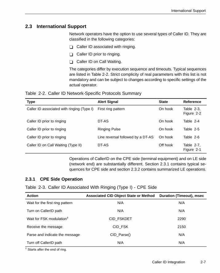
2.3 International SupportNetwork operators have the option to use several types of Caller ID. They areclassified in the following categories:
� Caller ID associated with ringing.
� Caller ID prior to ringing.
� Caller ID on Call Waiting.
The categories differ by execution sequence and timeouts. Typical sequencesare listed in Table 2-2. Strict complicity of real parameters with this list is notmandatory and can be subject to changes according to specific settings of theactual operator.
Table 2-2. Caller ID Network-Specific Protocols Summary
Type Alert Signal State Reference
Caller ID associated with ringing (Type I) First ring pattern On hook Table 2-3,Figure 2-2
Caller ID prior to ringing DT-AS On hook Table 2-4
Caller ID prior to ringing Ringing Pulse On hook Table 2-5
Caller ID prior to ringing Line reversal followed by a DT-AS On hook Table 2-6
Caller ID on Call Waiting (Type II) DT-AS Off hook Table 2-7,Figure 2-1
Operations of CallerID on the CPE side (terminal equipment) and on LE side(network end) are substantially different. Section 2.3.1 contains typical se-quences for CPE side and section 2.3.2 contains summarized LE operations.
2.3.1 CPE Side Operation
Table 2-3. Caller ID Associated With Ringing (Type I) - CPE Side
Action Associated CID Object State or Method Duration (Timeout), msec
Wait for the first ring pattern N/A N/A
Turn on CallerID path N/A N/A
Wait for FSK modulation† CID_FSKDET 2290
Receive the message CID_FSK 2150
Parse and indicate the message CID_Parse() N/A
Turn off CallerID path N/A N/A
† Starts after the end of ring.

International Support
2-8
Table 2-4. Caller ID Prior to Ringing Alerted by DT-AS - CPE Side
Action Associated CID Object State or Method Duration (Timeout), msec
Turn on CallerID path N/A N/A
Wait for DT-AS signal CID_DTAS infinite (0)
Wait for FSK modulation CID_FSKDET 790
Receive the message CID_FSK 2150
Parse and indicate the message CID_Parse() N/A
Table 2-5. Caller ID Prior to Ringing Alerted by Ringing Pulse - CPE Side
Action Associated CID Object State or Method Duration (Timeout), msec
Wait for the first ringing pulse N/A N/A
Turn on CallerID path N/A N/A
Wait for FSK modulation† CID_FSKDET 1090
Receive the message CID_FSK 2150
Parse and indicate the message CID_Parse() N/A
† Starts on trailing edge of ringing pulse.
Table 2-6. Caller ID Prior to Ringing Alerted by Line Reversal + DT-AS - CPE Side
Action Associated CID Object State or Method Duration (Timeout), msec
Wait for line reversal N/A N/A
Apply AC/DC load and DCwetting pulse (optionally)
N/A N/A
Turn on CallerID path N/A N/A
Wait for DT-AS signal† CID_DTAS 655
Wait for FSK modulation CID_FSKDET 1090
Receive the message CID_FSK 2150
Parse and indicate the message CID_Parse() N/A
Wait CID_WAIT 100
Remove AC/DC load (optionally)and turn off CallerID path
N/A N/A
† Starts on line reversal detection.

International Support
2-9Caller ID Integration
Table 2-7. Caller ID on Call Waiting. CPE side
Action Associated CID Object State or Method Duration (Timeout), msec
Wait for DT-AS signal† CID_DTAS infinite (0)
Block speech path N/A N/A
Send TE-ACK acknowledgement CID_TEACK 300
Wait for FSK modulation CID_FSKDET 295
Receive the message CID_FSK 2150
Parse and indicate the message CID_Parse() N/A
Wait CID_WAIT 40…120
Restore speech path N/A
† Good talk-off performance of DT-AS detector offers waiting during the whole off-hook state.
Notes: CPE Side Operations
� All timeouts include appropriated detection delays.
� Timeouts for FSK modulation include maximum channel seizure dura-tion 315 bits for SIN227 standard. In some countries, these timeouts canbe reduced.
� In case of any error, Caller ID path should be turned off if it was enabledpreviously.
� Although ringing pulse duration should be in 200…300 msec range, insome networks it may extend to 450 msec and be accompanied by a po-larity reversal. Also, any frequency in range of 15 to 75 Hz should be ac-cepted.
� Some exchanges (for example, complying with SIN227 standard) re-quire AC or DC load switching in addition to enabling Caller ID path inon-hook state. The detailed operation is described in appropriate recom-mendations (see Calling Line Identification Service, British Telecommu-nication plc, SIN227, Issue 03 and Calling Line Identification Service, TEEquipment Requirement, British Telecommunication plc, SIN242, Issue02, Nov., 1996).

International Support
2-10
2.3.2 Local Exchange Side Operation
Table 2-8 through Table 2-12 characterize optimal methods for using Caller-ID software on LE side. Some implementations require more complicatedstate machines to accomplish more robust operations, but using the CID ob-ject will provide basic processing.
Timeouts listed below are subject to change according the specific countrystandards and indicate typical values for most European countries.
Table 2-8. Caller ID Associated With Ringing (Type I) - LE Side
Action Associated CID Object State or Method Duration (Timeout), msec
Encode the message CID_Parse() N/A
Send the first ring pattern N/A N/A
Wait† CID_WAIT 800
Send FSK modulation CID_FSKGEN 2290
† After the end of ring.
Table 2-9. Caller ID Prior to Ringing Alerted by DT-AS - LE Side
Action Associated CID Object State or Method Duration (Timeout), msec
Encode the message CID_Parse() N/A
Send DT-AS signal CID_DTASGEN 150
Wait CID_WAIT 300
Send FSK modulation CID_FSKGEN 2290
Table 2-10. Caller ID Prior to Ringing Alerted by Ringing Pulse - LE Side
Action Associated CID Object State or Method Duration (Timeout), msec
Encode the message CID_Parse() N/A
Send ringing pulse N/A N/A
Wait CID_WAIT 650
Send FSK modulation CID_FSKGEN 2290

International Support
2-11Caller ID Integration
Table 2-11. Caller ID Prior to Ringing Alerted by Line Reversal + DT-AS - LE Side
Action Associated CID Object State or Method Duration (Timeout), msec
Encode the message CID_Parse() N/A
Change polarity N/A N/A
Wait CID_WAIT 200
Send DT-AS signal CID_DTASGEN 150
Wait CID_WAIT 300
Send FSK modulation CID_FSKGEN 2290
Table 2-12. Caller ID on Call Waiting - LE Side
Action Associated CID Object State or Method Duration (Timeout), msec
Encode the message CID_Parse() N/A
Block speech path N/A N/A
Wait CID_WAIT 100
Send DT-AS signal and receiveTE-ACK†
CID_DTASTEACK 185
Wait CID_WAIT 70
Send FSK modulation CID_FSKGEN 2290
Wait CID_WAIT 40
Restore speech path N/A N/A
† When no TE-ACK signal is received, restore speech path in <150 msec.

International Support
2-12
2.3.3 DTMF-Based CallerID Reception and Transmission
Various network operators use DTMF-based signaling protocol to provide sub-scribers with information about the calling party. SPIRIT’s implementation ofCallerID contains complete DTMF message decoders and message genera-tors that acquire data in common data-link format and converts them intoDTMF digits internally.
Table 2-13. DTMF-Based Caller ID operation - CPE Side
Action Associated CID Object State or Method Duration (Timeout), msec
Wait for DIT state:
� wait for line reversal
� detect the voltage hasreached at least 30 V
N/A N/A
Turn on CallerID path N/A N/A
Receive DTMF-message CID_DTMFDET 4000
Parse and indicate the message CID_Parse() N/A
Wait CID_WAIT 40…120
Turn on CallerID path N/A N/A
Table 2-14. DTMF-Based Caller ID Operation - LE Side
Action Associated CID Object State or Method Duration (Timeout), msec
Encode the message CID_Parse() N/A
Reverse polarity N/A N/A
Wait CID_WAIT 100
Send DTMF-message CID_DTMFGEN 4000
Wait CID_WAIT 50
Specific Issues
2-13Caller ID Integration
2.4 Specific Issues
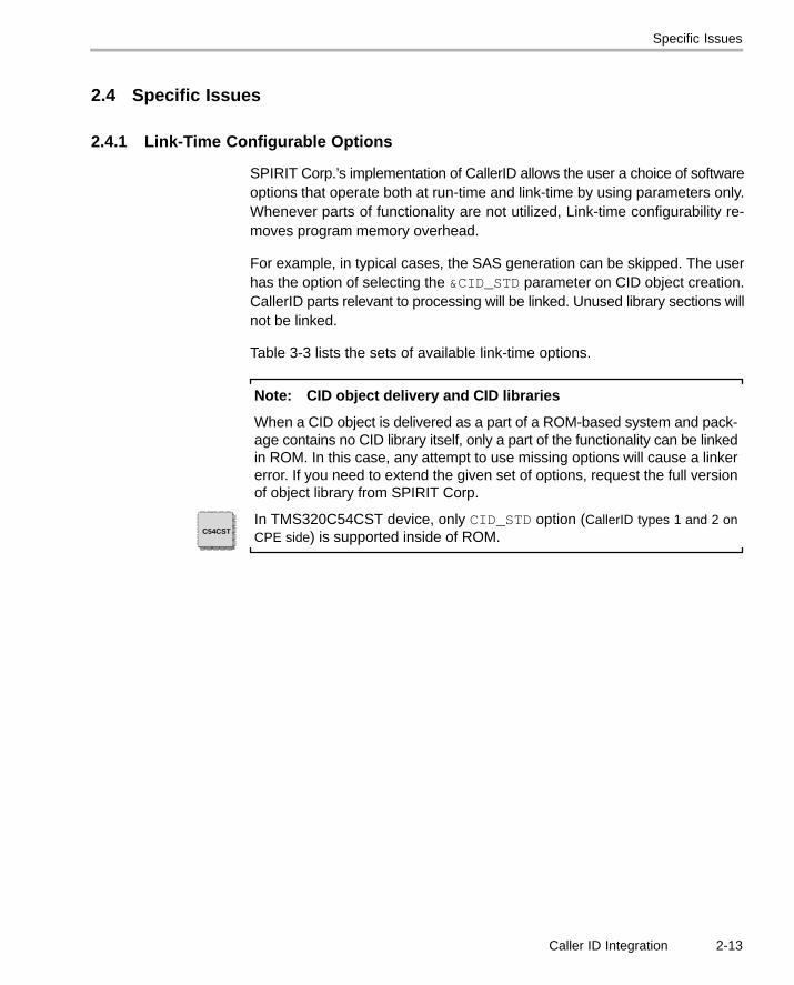
2.4.1 Link-Time Configurable Options
SPIRIT Corp.’s implementation of CallerID allows the user a choice of softwareoptions that operate both at run-time and link-time by using parameters only.Whenever parts of functionality are not utilized, Link-time configurability re-moves program memory overhead.
For example, in typical cases, the SAS generation can be skipped. The userhas the option of selecting the &CID_STD parameter on CID object creation.CallerID parts relevant to processing will be linked. Unused library sections willnot be linked.
Table 3-3 lists the sets of available link-time options.
Note: CID object delivery and CID libraries
When a CID object is delivered as a part of a ROM-based system and pack-age contains no CID library itself, only a part of the functionality can be linkedin ROM. In this case, any attempt to use missing options will cause a linkererror. If you need to extend the given set of options, request the full versionof object library from SPIRIT Corp.
In TMS320C54CST device, only CID_STD option (CallerID types 1 and 2 onCPE side) is supported inside of ROM.C54CST

Specific Issues
2-14
2.4.2 Detection Delays
Each kind of detector stage introduces a specific delay. These types of delaysare summarized in Table 2-15. Additionally, real delay depends on the size ofbuffer passed to the detector. A delay cannot be less than buffer_size/8[msec].
Table 2-15. Caller ID Detection Delays
State Delay, msec
CID_DONOTHING N/A
CID_SAS N/A
CID_DTAS 25 … mDTAS.mDuration+25, see Table 3-2 and Table 3-5
CID_TEACK N/A
CID_FSKDET 25
CID_FSK 4, At first, detector waits for modulation duringmBITSYNC.mMarkTimeout*0.833 msec (see Table 3-2 and Table 3-8). Later,detector leaves its state when no FSK pulse is arrived during 1.25 msec (1.5 bitsperiods)
CID_DTASGEN N/A
CID_TEACKDET 13
CID_DTASTEACK 13
CID_FSKGEN N/A
CID_WAIT 0

Integration by Using the CIDWRAPPER Class
2-15Caller ID Integration
2.5 Integration by Using the CIDWRAPPER Class
SPIRIT Corp. supplies a complete CID API including a simple wrapper classCIDWRAPPER. This class contains a state machine for consecutive executionsof CID object states and allows easy implementation of any Caller ID standard.
API functions of this class are described in section 3.5.
Example of a Call Sequence
2-16
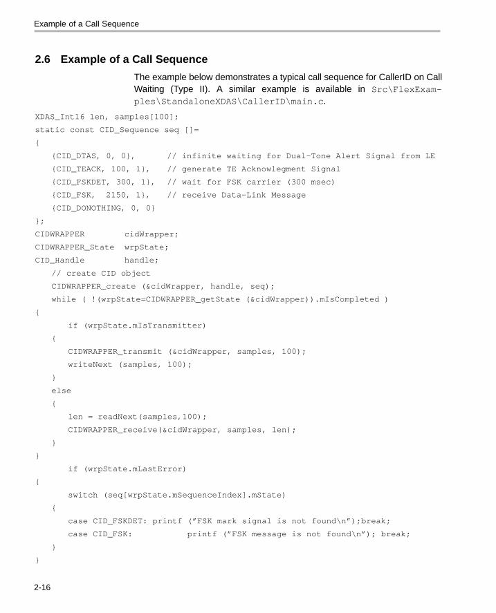
2.6 Example of a Call Sequence
The example below demonstrates a typical call sequence for CallerID on CallWaiting (Type II). A similar example is available in Src\FlexExam-ples\StandaloneXDAS\CallerID\main.c.
XDAS_Int16 len, samples[100];
static const CID_Sequence seq []=
{
{CID_DTAS, 0, 0}, // infinite waiting for Dual-Tone Alert Signal from LE
{CID_TEACK, 100, 1}, // generate TE Acknowlegment Signal
{CID_FSKDET, 300, 1}, // wait for FSK carrier (300 msec)
{CID_FSK, 2150, 1}, // receive Data-Link Message
{CID_DONOTHING, 0, 0}
};
CIDWRAPPER cidWrapper;
CIDWRAPPER_State wrpState;
CID_Handle handle;
// create CID object
CIDWRAPPER_create (&cidWrapper, handle, seq);
while ( !(wrpState=CIDWRAPPER_getState (&cidWrapper)).mIsCompleted )
{
if (wrpState.mIsTransmitter)
{
CIDWRAPPER_transmit (&cidWrapper, samples, 100);
writeNext (samples, 100);
}
else
{
len = readNext(samples,100);
CIDWRAPPER_receive(&cidWrapper, samples, len);
}
}
if (wrpState.mLastError)
{
switch (seq[wrpState.mSequenceIndex].mState)
{
case CID_FSKDET: printf (”FSK mark signal is not found\n”);break;
case CID_FSK: printf (”FSK message is not found\n”); break;
}
}
3-1
CallerID (CID) API Descriptions
This chapter provides the user with a clear understanding of CallerID (CID) al-gorithms and their implementation with the TMS320 DSP Algorithm Standardinterface (XDAIS).
Topic Page
3.1 Standard Interface Structures 3-2. . . . . . . . . . . . . . . . . . . . . . . . . . . . . . . . . .
3.2 Standard Interface Functions 3-11. . . . . . . . . . . . . . . . . . . . . . . . . . . . . . . . .
3.3 Vendor-Specific Interface Structures 3-13. . . . . . . . . . . . . . . . . . . . . . . . . .
3.4 Vendor-Specific Interface Functions 3-21. . . . . . . . . . . . . . . . . . . . . . . . . .
3.5 The CIDWRAPPER Class API Reference 3-26. . . . . . . . . . . . . . . . . . . . . .
Chapter 3

Standard Interface Structures
3-2
3.1 Standard Interface StructuresThis section describes Standard parameter structures for Caller ID.
Table 3-1 lists the standard Interface Structures for CallerID API.
Table 3-1. CallerID Standard Interface Structures
Parameters Located in Table...
Instance Creation Table 3-2
Link-Time Configurable Options Table 3-3
SAS Signal Table 3-4
DT-AS Detector Table 3-5
TE-ACK Signal Table 3-6
FSK Carrier Detector Table 3-7
Bit Synchronizer Table 3-8
DT-AS Generator Table 3-9
TE-ACK Detector Table 3-10
FSK Generator Table 3-11
DTMF Decoder Table 3-12
DTMF Encoder Table 3-13
Russian Caller ID Table 3-14

Standard Interface Structures
3-3CallerID (CID) API Descriptions
3.1.1 Instance Creation Parameters
Description This structure defines the creation parameters for the algorithm. A default pa-rameter structure is defined in “iCID.c”.
Client has to specify basic Caller ID parameters in ICID_Params on creationof the CID detector (see CID_create() function, section 3.2.3).
Structure Definition
Table 3-2. Instance Creation Parameters
typedef struct ICID_Params {
Parameter typeParameterName Description
Affected States(see Table 3-17)or Functions
const CID_Options* options Link-time configurable options (see Table 3-3) all
CID_DataLinkMessage* pMessage Pointer to the parsed message. Make sure thatmpMessage is not out of scope during the lifetimeof CID_Handle (see Table 3-18)
CID_FSKG,CID_FSKGEN,CID_parse()
XDAS_Int16 maxLevel Maximum level of input signal.
CID_SASGenSignal sasGen SAS signal parameters (see Table 3-4) CID_SAS
CID_DTASDetSignal dtasDet DT-AS signal parameters (see Table 3-5) CID_DTAS
CID_TEACKGenSignal teackGen TE-ACK signal parameters (see Table 3-6) CID_TEACK
CID_FSKDetSignal fskDet FSK carrier detector parameters (see Table 3-7) CID_FSKDET
CID_BitSyncSignal bitSync Bit synchronizer parameters (see Table 3-8) CID_FSK
CID_DTASGenSignal dtasGen DT-AS signal generator parameters (seeTable 3-9)
CID_DTASGEN,CID_DTASTEACK
CID_TEACKDetSignal teackDet TE-ACK signal detector parameters (seeTable 3-10)
CID_TEACKDET,CID_DTASTEACK
CID_FSKGenSignal fskGen FSK generator parameters (see Table 3-11) CID_FSKGEN
CID_DTMFDetSignal dtmfDet DTMF-message decoder parameters (seeTable 3-12)
CID_DTMFDET
CID_DTMFGenSignal dtmfGen DTMF-message encoder parameters (seeTable 3-13)
CID_DTMFGEN
CID_R15Signal r15 Russian Caller ID detector parameters (seeTable 3-14)
CID_R15
} ICID_Params
Type ICID_Params is defined in “iCID.h”. The following types are used:

Standard Interface Structures
3-4
3.1.2 Link-Time Configurable Options
Table 3-3. Link-Time Configurable Options
OptionSupported States(see Table 3-17) Functionality
&ICID_STD CID_DTASCID_TEASKCID_FSKCID_FSKDETCID_WAITK
Limited. Support both CallerID of types 1 and 2 on CPE side.
&ICID_STDDTMF CID_DTASCID_TEASKCID_FSKCID_FSDETCID_DTMFDETCID_WAIT
Limited. Support both CallerID of types 1 and 2 on CPE sideand DTMF-based subscriber decoder.
&ICID_LE CID_DTASGENCID_TEASKDETCID_DTASTEASKCID_FSKGENCID_SASCID_DTMFGENCID_WAIT
Limited. Support both CallerID of types 1, 2 and DTMF-based message generator on local exchange side.
&ICID_FULL all listed in Full
3.1.3 SAS Signal Parameters
Table 3-4. SAS Signal Parameters
typedef struct
{
Parameter Type Parameter Name Typical ValueAcceptable
Limits Description
XDAS_Int16 duration 200 >0 duration (in msec)
XDAS_Int16 toneLevel 0x4000 (-6 dB) 0…0x7FFF tone level (Q15.0 format).0x7FFF corresponds to thefull-scale sine-wave.
}
CID_SASGenSignal;

Standard Interface Structures
3-5CallerID (CID) API Descriptions
3.1.4 DT-AS Detector Parameters
Table 3-5. DT-AS Detector Parameterstypedef struct
{
ParameterType Parameter Name Typical Value
AcceptableLimits Description
XDAS_Int16 duration 50 50…100 minimum acceptable duration (inmsec)
XDAS_Int16 twist 0x32F5 (8 dB) 0x2000…0x7FFF
max tones twist (Q15.0 format)
XDAS_Int16 toneLevel 1036 (-30 dB) 0…0x7FFF Detector sensitivity. This parame-ter controls minimum signal levelper tone to be accepted by detec-tor. (Q15.0 format - 0x7FFF cor-responds to the full-scale sine-wave)
XDAS_Int16 spuriousLevel 0x2000 (-12 dB) 0x1000…0x4000
Acceptable relative spurious lev-el. (Q15.0 format). Greater valuesenhance tone recognition, butmake worse talk-off performance.
}
CID_DTASDetSignal;
3.1.5 TE-ACK Signal Parameters
Table 3-6. TE-ACK Signal Parameterstypedef struct
{
Parameter Type Parameter Name Typical ValueAcceptable
Limits Description
XDAS_Int16 duration 80 65…90 Duration of TE-ACK signal,msec
XDAS_Int8 dtmfSymbol ’D’ ’A’,’B’,’C’,’D’ DTMF symbol to be gener-ated. Network operator op-tion.
XDAS_Int16 toneLevel 00x4000 (-6 dB) 0…0x4000 Generated signal level pertone (Q15.0 format) - 0x7FFFcorresponds to the full-scalesine-wave
}
CID_TEACKGenSignal;

Standard Interface Structures
3-6
3.1.6 FSK Carrier Detector Parameters
Table 3-7. FSK Carrier Detector Parameters
typedef struct
{
Parameter Type Parameter Name Typical ValueAcceptable
Limits Description
XDAS_Int16 toneLevel 583 (-35dB) 100…0x7FFF Detector sensitivity. This pa-rameter controls minimumsignal level per tone to be ac-cepted by detector. (Q15.0format - 0x7FFF correspondsto the full-scale sine-wave)
XDAS_Int16 spuriousLevel 10362 (-10 dBc) 0x2000…0x4000
Acceptable relative spuriouslevel. (Q15.0 format). Greatervalues enhance tone recogni-tion but make worse talk-offperformance.
}
CID_FSKDetSignal;
3.1.7 Bit Synchronizer Parameters
Table 3-8. Bit Synchronizer Parameters
typedef struct
{
ParameterType
ParameterName
TypicalValue
AcceptableLimits Description
XDAS_Int16 clockRate 08000 8000 Clock rate (samples per second). Mustbe equal to 8000.
XDAS_Int16 bitRate 01200 1100…1300 Bit rate (bits per second)
XDAS_Int16 markTimeout 0190 80…300 Maximum mark bit duration (in bit counts)
}
CID_BitSyncSignal;

Standard Interface Structures
3-7CallerID (CID) API Descriptions
3.1.8 DT-AS Generator Parameters
Table 3-9. DT-AS Generator Parameters
typedef struct
{
Parameter Type Parameter Name Typical ValueAcceptable
Limits Description
XDAS_Int16 duration 90 50…110 Duration (in msec) of DT-ASsignal to be generated
XDAS_Int16 twist 0x3FFF (0 dB) 0x2000…0x7FFF
(-6 …+6dB)
Tone twist (Q14.1 format)
XDAS_Int16 toneLevel 0x4000 (-6 dB) 0…0x7FFF Generated signal level pertone (Q15.0 format) - 0x7FFFcorresponds to the full-scalesine-wave
}
CID_DTASGenSignal;
3.1.9 TE-ACK Detector Parameters
Table 3-10. TE-ACK Detector Parameters
typedef struct{
Parameter Type Parameter Name Typical ValueAcceptable
Limits Description
XDAS_Int16 duration 50 50…80 Minimum acceptable duration(in msec)
XDAS_Int8 dtmfSymbol ’D’ ’A’, ’B’, ’C’ ,’D’, 0 DTMF symbol to be detected.When any of the listed sym-bols can be accepted, 0should be passed
XDAS_Int16 twist 0x32F5 (8 dB) 0x2000…0x7FFF
Max tone twist (Q15.0 format)

Standard Interface Structures
3-8
Table 3–10. TE-ACK Detector Parameters (Continued)
typedef struct{
Parameter Type DescriptionAcceptable
LimitsTypical ValueParameter Name
XDAS_Int16 toneLevel 1036 (–30 dB) 0…0x7FFF Detector sensitivity. This pa-rameter controls minimumsignal level per tone to be ac-cepted by detector. (Q15.0format – 0x7FFF correspondsto the full-scale sine-wave)
XDAS_Int16 spuriousLevel 10362 (–10 dB) 0x1000…0x4000
Acceptable relative spuriouslevel. (Q15.0 format). Greatervalues enhance tone recogni-tion but make worse talk-offperformance.
} CID_TEACKDetSignal;
3.1.10 FSK Generator Parameters
Table 3–11. FSK Generator Parameters
typedef struct
{
Parameter Type Parameter Name Typical ValueAcceptable
Limits Description
XDAS_Int16 modulationType 01 0, 1 Used modulation:0 – Bell 2021 – V.23
XDAS_Int16 preambleMark 080 55…205 Preamble mark bit duration(in bit counts)
XDAS_Int16 channelSeizure 0120 96…315 Channel seizure duration (inbit counts)
XDAS_Int16 signalLevel 6925 (–13.5 dB) 0…0x7FFF Level of FSK signal (Q15.0format) – 0x7FFF corre-sponds to the full-scale sine-wave
}
CID_FSKGenSignal
Standard Interface Structures
3-9CallerID (CID) API Descriptions
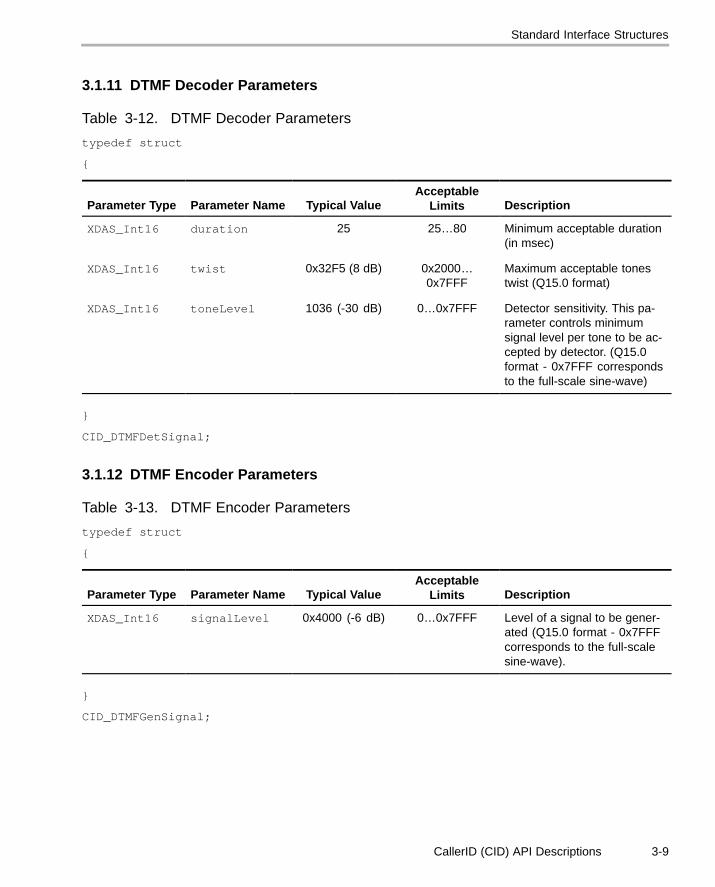
3.1.11 DTMF Decoder Parameters
Table 3-12. DTMF Decoder Parameters
typedef struct
{
Parameter Type Parameter Name Typical ValueAcceptable
Limits Description
XDAS_Int16 duration 25 25…80 Minimum acceptable duration(in msec)
XDAS_Int16 twist 0x32F5 (8 dB) 0x2000…0x7FFF
Maximum acceptable tonestwist (Q15.0 format)
XDAS_Int16 toneLevel 1036 (-30 dB) 0…0x7FFF Detector sensitivity. This pa-rameter controls minimumsignal level per tone to be ac-cepted by detector. (Q15.0format - 0x7FFF correspondsto the full-scale sine-wave)
}
CID_DTMFDetSignal;
3.1.12 DTMF Encoder Parameters
Table 3-13. DTMF Encoder Parameters
typedef struct
{
Parameter Type Parameter Name Typical ValueAcceptable
Limits Description
XDAS_Int16 signalLevel 0x4000 (-6 dB) 0…0x7FFF Level of a signal to be gener-ated (Q15.0 format - 0x7FFFcorresponds to the full-scalesine-wave).
}
CID_DTMFGenSignal;

Standard Interface Structures
3-10
3.1.13 Russian Caller ID Parameters
Table 3-14. Instance Creation Parameters
typedefstruct{
Parameter Type Parameter Name Typical ValueAcceptable
Limits Description
XDAS_Int16 genDuration 160 0…0x7FFF Minimum acceptable duration(in msec)
XDAS_Int16 genAmplitude 0x7fff (0 dB) 0-9 Level of a signal to be gener-ated (Q15.0 format - 0x7FFFcorresponds to the full-scalesine-wave).
XDAS_Int16 inquiriesCount 3 250-275 Quantity of inquiries. If thisfield is equal to zero, the inqui-ry is not dispatched.
XDAS_Int16 startDelay 260 Delay before sending of inqui-ry after call.
XDAS_Int16 pauseBetween 50 Pause between inquiries.
XDAS_Int16 detectDuration 1000 Signal analysis duration (inmsec).
XDAS_Int16 toneLevel 1036 (-30 dB) 0…0x7FFF Detector sensitivity. This pa-rameter controls minimum sig-nal level per tone to be accept-ed by detector. (Q15.0 format- 0x7FFF corresponds to thefull-scale sine-wave)
XDAS_Int16 spuriousLevel 10362 (-10 dB) 0x1000…0x4000
Acceptable relative spuriouslevel. (Q15.0 format). Greatervalues enhance tone recogni-tion but make worse talk-offperformance.
} CID_R15Signal;

CID_exit
3-11
3.2 Standard Interface Functions
Table 3-15 summarizes the standard Interface functions of CallerID API.These functions are required when using the CID algorithm CID.
CID_apply() and CID_control() are optional, but neither are supported by SpiritCorp.
Table 3-15. CallerID Standard Interface Functions
Functions Description See Page...
CID_init Calls the framework initialization function (Algorithm initialization) 3-11
CID_exit Calls the framework exit function (Algorithm deletion) 3-11
CID_create Calls the framework creation function (Instance creation) 3-12
CID_delete Calls the framework deletion function (Instance deletion) 3-12
3.2.1 Algorithm Initialization
Calls ALG_init() to initialize a CID algorithmCID_init
Function Prototype void CID_init()
Arguments none
Description This function calls the framework initialization function, ALG_init(), toinitialize the CID algorithm. For SPIRIT’s CallerID, this function does nothing.It can be skipped and removed from the target code according to The TMS320DSP Algorithm Standard (SPRA581).
Return Value none
3.2.2 Algorithm Deletion
Calls ALG_exit() to remove a CID algorithmCID_exit
Function Prototype void CID_exit()
Arguments none
Description This function calls the framework exit function, ALG_exit(), to remove theCID algorithm.For SPIRIT Corp.’s implementation of CallerID, this functiondoes nothing. It can be skipped and removed from the target code accordingto The TMS320 DSP Algorithm Standard (SPRA581).
Return Value none

CID_create
3-12
3.2.3 Instance Creation
Function called to create a new CID decoder objectCID_create
Function Prototype CID_Handle CID_create (const ICID_Fxns *fxns, constICID_Params *prms);
Description In order to create a new CID decoder object, CID_create function shouldbe called. This function calls the framework create function, ALG_create(),to create the instance object and perform memory allocation tasks. Globalstructure CID_SPCORP_ICID contains CID virtual table supplied by SPIRITCorp.
Arguments ICID_Fxns * Pointer to vendor’s functions (Implementation ID).Use reference to CID_SPCORP_ICID virtual table supplied by SPIRIT Corp.
ICID_Params * Pointer to Parameter Structure (see section 3.1.1).Use NULL pointer to load default parameters.
Return Value CID_Handle defined in file “CID.h”. This is a pointer to the created instance object.
Restrictions none
3.2.4 Instance Deletion
Function called to delete an instance objectCID_delete
Function Prototype void CID_delete (CID_Handle handle)
Arguments CID_Handle Instance’s handle obtained from CID_create()
Description This function calls the framework delete function, ALG_delete(), to deletethe instance object and perform memory de-allocation tasks.
Return Value none

Vendor-Specific Interface Structures
3-13
3.3 Vendor-Specific Interface Structures
In the following sections, parameter structures and functions in the SPIRIT’salgorithm implementation and interface (extended IALG methods) are de-scribed.
Table 3-16 summarizes the list of tables containing SPIRIT’s API interfacestructures.
Table 3-16. CallerID Vendor-Specific Interface Structures
Parameters Located in Table...
Bitmasks in CID_Message.validFields Table 3-21
Caller ID Error Codes Table 3-22
Caller ID States Table 3-17
Data-link Layer Table 3-18
Message Types Table 3-20
Presentation Layer Table 3-19

Vendor-Specific Interface Structures
3-14
3.3.1 Caller ID States
CID object can be configured either as transmitter of alert signal or as receiver.Actual state of CallerID object can be retrieved by CID_getState() (page3-22) and established by CID_setState() (page 3-21).
Table 3-17. Caller ID States
typedef enum
{
Enumeration Mode State
(a) Common states
CID_DONOTHING n/a does nothing
CID_WAIT receiver does nothing and waits for timeout expiration
(b) TE (CPE) side
CID_DTAS receiver receives DTAS signal
CID_TEACK transmitter generates TEACK signal
CID_FSKDET receiver receives FSK carrier
CID_FSK receiver receives FSK message (including data-link layer)
CID_R15 receiver receives Russian CallerID decoder
CID_DTMFDET receiver receives DTMF-based message and converts it into genericdata-link layer
(c) LE side
CID_DTASGEN transmitter generates DT-AS signal
CID_TEACKDET receiver receives TE-ACK signal from TE
CID_DTASTEACK transmitter andreceiver
generates DT-AS signal and receives TE-ACK signal from TEsimultaneously
CID_SAS transmitter generates SAS signal
CID_FSKGEN transmitter generates V.23 of Bell 202 FSK modulated message
CID_DTMFGEN transmitter generates DTMF-based message
}
CID_State0;

Vendor-Specific Interface Structures
3-15
3.3.2 Data-Link Level Message
Data-link level message structure CID_DataLinkMessage contains unfor-matted bytes that were received during CID_FSK, CID_DTMFDET CID ob-ject states, and bytes to be transmitted during CID_FSKGEN, CID_DTMFGENstates (DTMF-based detector/transmitter automatically converts DTMF-digitsinto appropriate fields of data-link level message).
Table 3-18. Data-Link Layer Structure
typedef struct
{
Parameter Type Parameter Name Description
XDAS_UInt8 type Message type
0x04 - SDMF,
0x80 - MDMF (Call Setup),
0x82 - Message Waiting Indicator,
0x86 - Advise of Charge
XDAS_UInt8 length number of valid bytes in the unformatted message
XDAS_UInt8 presenta-tion[253]
unformatted message
XDAS_UInt8 checksum checksum
XDAS_UInt16 lastError last error:
0x00 - no error,
0x10 – checksum error
0x11 - frame length error (unrecoverable)
0x12 – unrecognized message type (unrecoverable)
}
CID_DataLinkMessage
Data-link layer can be converted into presentation layer and back by usingfunction CID_parse(), see section 3.4.6.

Vendor-Specific Interface Structures
3-16
3.3.3 Presentation Level Message
Presentation level structure CID_Message holds all possible parameters thatcan be received during the Caller ID transaction. Bit masks in the valid-Fields define the set of currently available fields. In any case, all unusedfields are set to 0. Fields of this structure are corresponded to clause 7 of PublicSwitched Telephone Network (PSTN); Subscriber line protocol over the localloop for display (and related) services; Part 1: On hook data transmission, ETS300 659-1, DE/SPS-03034-1.
Function CID_parse() (see 3.4.6) converts both SDMF and MDMF mes-sage into the presentation layer. Also, this function provides reverse conver-sion for using on LE-side equipment.
Table 3-19. Presentation Layer Structure
typedef struct
{
Parameter Type Parameter Name Description
CID_Messagetype type Message type (see Table 3-20)
XDAS_Int8 [9] date Date and time of a call
XDAS_Int8 [21] callingLineIndentity Identifies the origin of a call
XDAS_Int8 [21] calledLineIndentity Identifies the called party
XDAS_Int8 [51] callingPartyName Identifies the name of the party atthe origin of a call
XDAS_Int8 [21] firstLineIndentity In case of forwarded call, it identifiesthe first called party
XDAS_Int8 [21] redirectedNumber In case of forwarded call only
XDAS_Int8 [21] complementaryCallingLineIndentity
XDAS_int8 reasonForAbsence The purpose of the Reason for Ab-sence of Calling Line Identity param-eter is to describe the reason for ab-sence of Calling Line Identity. Canassume one of 2 values:
(’O’): Unavailable (probably out ofrange)
(’P’): Private (CLIR involved) call

Vendor-Specific Interface Structures
3-17
Table 3-19. Presentation Layer Structure (Continued)
Parameter Type DescriptionParameter Name
XDAS_int8 reasonForAbsenceOfParty Describes the reason for absence ofthe Calling Party Name. Can as-sume one of 2 values:
(’O’): Unavailable
(’P’): Private (CLIR involved) call
Values in the range 8016-FF16 arereserved for network operators.
XDAS_int08 callType Specifies the type of a call.
0116 Voice Call
0216 CLI Ring Back in case offree call
0316 Calling Name Delivery
7F16 Set Clock
8116 Message Waiting Call
Values in the range 8216-FF16 arereserved for network operators.
XDAS_int8 visualInicator The purpose of this parameter is toswitch on/off a visual indicator (pres-ence of waiting messages).
XDAS_int16 networkMessageSystemStatus Specifies the number of waitingmessages in the network messagesystem. Zero value means no mes-sages, value of 1 means 1 or un-specified numer of messages in thequeue, other values indicate thenumber of waiting messages.
XDAS_int8 typeOfForwardedCall Identifies the type of forwarded call:
0116: Call forwarded on busy
0216: Call forwarded on no reply
0316: Unconditional forwarded call
0416: Deflected call (after alerting)
0516: Deflected call (immediate)
0616: Call forwarded on inability toreach mobile subscriber
Values in the range E016-FF16 arereserved for network operators.

Vendor-Specific Interface Structures
3-18
Table 3-19. Presentation Layer Structure (Continued)
Parameter Type DescriptionParameter Name
XDAS_int8 typeOfCallingUser 0016: Origination unknown or un-available
0316: Virtual Private Network
0416: Mobile phone
0516: Mobile phone + Virtual PrivateNetwork
0A16: Ordinary calling subscriber
0B16: Calling subscriber with priority
0C16: Data Call
0D16: Test call
0F16: Payphone
XDAS_Int8 [10] extension
XDAS_UInt16 lastError last error:
0x00 - no error,
0x10 - checksum error
0x11 - frame length error (unrecov-erable)
0x12 - unrecognized message type(unrecoverable)
XDAS_Int16 validFields Bit mask for available fields (seeTable 3-21)
}
CID_Message
Enumeration constants CID_MessageType define currently available mes-sage format.

Vendor-Specific Interface Structures
3-19
Table 3-20. Message Types
typedef struct
{
Enumeration Constant Value Description
CID_NONE 0 No available messages
CID_SDMF 0x040 Message is in the SDMF format
CID_MDMF 0x800 Message is in the MDMF format
CID_MESSAGEWAITING 0x82 Message is in the VMWI format
CID_ADVISE 0x86 Message contains information about actual balance ofpayment
}
CID_MessageType
Bitmasks in CID_Message.validFields allow defining the set of validfields in the currently available Caller ID message. To validate variable xxxfrom presentation level CID_Message, you have to perform AND operationon CID_Message.validFields with bit mask CID_xxx.
Table 3-21. Bit Masks in CID_Message.validFields
Enumeration Description
CID_DATE CID_Message.date field is valid
CID_CALLINGLINEINDENTITY CID_Message.callingLineIndentity field isvalid
CID_CALLEDLINEINDENTITY CID_Message.calledLineIndentity field is valid
CID_CALLINGPARTYNAME CID_Message.callingPartyName field is valid
CID_FIRSTLINEINDENTITY CID_Message.firstLineIndentity field is valid
CID_REDIRECTEDNUMBER CID_Message.redirectedNumber field is valid
CID_COMPLEMENTARYCALLINGLINEINDENTITY CID_Message.complementaryCallingLineInd-entity field is valid
CID_REASONFORABSENCE CID_Message.reasonForAbsence field is valid
CID_REASONFORABSENCEOFPARTY CID_Message.reasonForAbsenceOfParty field isvalid
CID_CALLTYPE CID_Message.callType field is valid
CID_VISUALINICATOR CID_Message.visualInicator field is valid

Vendor-Specific Interface Structures
3-20
Table 3-21. Bit Masks in CID_Message.validFields (Continued)
Enumeration Description
CID_NETWORKMESSAGESYSTEMSTATUS CID_Message.networkMessageSystemStatusfield is valid
CID_EXTENSION CID_Message.extension field is valid
CID_TYPEOFFORWARDEDCALL CID_Message.typeOfForwardedCall field is valid
CID_TYPEOFCALLINGUSER CID_Message.typeOfCallingUser field is valid
3.3.4 Caller ID Error Codes
Enumeration constants CID_Error define currently available error codesthat can be retrieved by CID_getLastError() function.
Table 3-22. Caller ID Error Codes
typedef struct
{
Enumeration Constant Description
(a) generic error codes
CID_NOERROR no error
CID_TIMEOUT state was broken due to the timeout
CID_INVALIDSTATE state is not supported or not linked on instance creation (see Table 3-2 andTable 3-3)
(b) specific error codes for CID_FSK state
CID_CHECKSUMERROR checksum error was detected
CID_ILLEGALLENGTH improper message length (less than 3 octets or more than 258 octets)
CID_UNKNOWNTYPE unknown message format (see CID_MessageType)
}
CID_Error
CID_setState
3-21
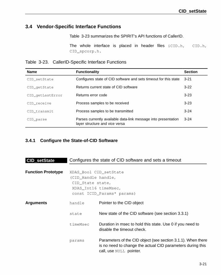
3.4 Vendor-Specific Interface Functions
Table 3-23 summarizes the SPIRIT’s API functions of CallerID.
The whole interface is placed in header files iCID.h, CID.h,CID_spcorp.h.
Table 3-23. CallerID-Specific Interface Functions
Name Functionality Section
CID_setState Configures state of CID software and sets timeout for this state 3-21
CID_getState Returns current state of CID software 3-22
CID_getLastError Returns error code 3-23
CID_receive Process samples to be received 3-23
CID_transmit Process samples to be transmitted 3-24
CID_parse Parses currently available data-link message into presentationlayer structure and vice versa
3-24
3.4.1 Configure the State-of-CID Software
Configures the state of CID software and sets a timeoutCID_setState
Function Prototype XDAS_Bool CID_setState (CID_Handle handle, CID_State state, XDAS_Int16 timeMsec, const ICID_Params* params)
Arguments handle Pointer to the CID object
state New state of the CID software (see section 3.3.1)
timeMsec Duration in msec to hold this state. Use 0 if you need to disable the timeout check.
params Parameters of the CID object (see section 3.1.1). When thereis no need to change the actual CID parameters during thiscall, use NULL pointer.

CID_getState
3-22
Description Configures state-of-CID software and sets timeout for this state. When timeoutexpires, software automatically selects CID_DONOTHING state.
Also, this function is used to change actual CallerID parameters “on-the-fly”.Parameters are copied into the internal structures so there is no need to storethem in static memory and lock this memory block. Moreover, they can be allo-cated on stack and leave the scope upon execution of this routine.
Return Value Always returns TRUE
Restrictions Field mOptions in params (link-time configurable options) is always ignoredso the set of selected options can be chosen on object creation only (see func-tion CID_create(), section 3.2.3).
3.4.2 Get Current State of CID
Returns current state of CID softwareCID_getState
Function Prototype CID_State CID_getState(ICID_Handle handle)
Arguments handle Pointer to CID object
Description Returns current state of CID software. CID_DONOTHING value indicates thatthe previously established state was finished.
The reason for switching can be retrieved by calling CID_getLastError()(see section 3.4.3)
Return Value Current state of CID (see Table 3-17).
Restrictions Maximum timeout value of state (parameter timeMsec of setState ()) islimited by 4095 milliseconds.

CID_receive
3-23
3.4.3 Get Error Code
Determines the cause of state switchingCID_getLastError
Function Prototype CID_Error CID_getLastError (ICID_Handle handle)
Arguments handle Pointer to CID object
Description Call this method to determine the cause of state switching. ReturnsCID_NOERROR if state was switched due to the normal completion ofreception/transmission.
Return Value Returns error code according to Table 3-22.
Restrictions none
3.4.4 Process Samples to be Received
Process number of input samples to be receivedCID_receive
Function Prototype XDAS_Bool CID_receive (ICID_Handle handle, const XDAS_Int16 samples[], XDAS_Int16 len)
Description Process number of input samples. Signal processing is performed accordingto the CID state previously established by CID_setState()(see 3.4.1).While CID object is in the transmitter mode or in the state CID_DONOTHING,it does nothing and returns immediately.
Arguments handle Pointer to CID object
const XDAS_Int16samples[] Array of input samples (at sample rate 8 kHz)
XDAS_Int16 len Number of samples to be processed
Return Value Returns TRUE when reception is finished (see CID_getState())
Restrictions The number of input samples for receive() must not exceed 300(37.5 msec input buffer).

CID_transmit
3-24
3.4.5 Process Samples to be Transmitted
Performs signal processing in transmission modeCID_transmit
Function Prototype XDAS_Bool0 CID_transmit (ICID_Handle handle, XDAS_Int16 samples[], XDAS_Int16 len0)
Arguments handle Pointer to CID object
XDAS_Int16samples[] Array of output samples (at sample rate 8 kHz)
XDAS_Int16 len Number of samples to be processed
Description Perform signal processing in transmission mode according to the CID statepreviously set by CID_setState(). Buffer is filled with zeroes when the CIDobject is in the receiver mode or in the state CID_DONOTHING.
Return Value Returns TRUE when transmission is finished (see CID_getState())
Restrictions none
3.4.6 Parse Data-link and Presentation Level Messages
Parses available data-link message into presentation layer structureCID_parse
Function Prototype XDAS_Void CID_parse (ICID_Handle handle, CID_Message* presentation, XDAS_Bool direction)
Arguments handle Pointer to CID object
presentation Presentation layer structure. See Table 3-19 fordetails.
direction Conversion direction:1 – convert data-link layer messageinto the presentation level.
0 – convert presentation level messageinto the data-link layer.

CID_parse
3-25
Description Parses currently available data-link message into presentation layer structureand vice versa. Can be performed even when CallerID reception is failed.Member validFields in the CID_Message masks available members(see Table 3-21).
Reference to data-link message is set on object creation (section 3.4.3) or es-tablishing the state of CID object (section 3.4.1) in the field ICID_Pa-rams::mpMessage (see Table 3-2).
Return Value none
Restrictions none

The CIDWRAPPER Class API Reference
3-26
3.5 The CIDWRAPPER Class API Reference
The CIDWRAPPER class allows consecutive execution of CallerID states toprovide the necessary timeouts, switching and error handling. This class is de-livered in open sources and can be used or modified in any way without anysubmissions to SPIRIT Corp.
Table 3-24 summarizes the Caller ID Wrapper structure classes.
Table 3-24. CIDWRAPPER Class API Reference Table Summary
CIDWRAPPER API Type Located in Table...
Caller ID Wrapper State Table 3-25
Caller ID Wrapper Sequence Table 3-26
3.5.1 Caller ID Wrapper State
Table 3-25. Caller ID Wrapper Statetypedef struct
{
Parameter Type Parameter Name Description
XDAS_Bool isCompleted TRUE when sequence was completed
XDAS_Bool isTransmitter TRUE when Caller ID is transmitter now
CID_Error lastError last error state
XDAS_Int16 sequenceIndex state being processed currently
}
CIDWRAPPER_State
3.5.2 Caller ID Wrapper Sequence
Table 3-26. Caller ID Wrapper Sequencetypedef struct
{
Parameter Type Parameter Name Description
CID_State state CID API state to be established
XDAS_Int16 timeoutMsec timeout value for state
XDAS_Bool isBreakOnError break sequencing when error occurs
}
CIDWRAPPER_Sequence;

The CIDWRAPPER Class API Reference
3-27
3.5.3 Caller ID Wrapper Functions
Table 3-27 lists the Caller ID Wrapper Functions.
Complete code is contained in the files “CIDWrapper.c”, “CIDWrap-per.h”.
Table 3-27. CIDWRAPPER Functions
Return TypeMethodName Parameters Type and Name Description
void create CIDWRAPPER *pthis – pointerto CIDWRAPPER object
CID_Handle cidHandle –existing handle to the CID object
const CID_Sequence seq[]– array of CID_Sequencemembers.
Recreates CIDWRAPPER objectand starts sequential CIDoperation. End of seq array ismarked byseq[xxx].mState==CID_DONOTHING
CIDWRAPPER_State getState CIDWRAPPER *pthis – pointerto CID CIDWRAPPER object
Returns current state ofCIDWRAPPER object.
void receive CIDWRAPPER *pthis – pointerto CID CIDWRAPPER object
const XDAS_Int16samples[] – array of inputsamples (at sample rate 8 kHz).
XDAS_Int16 len – number ofsamples to be processed
A simple wrapper to the CIDreceive() method
void transmit CIDWRAPPER *pthis – pointerto CID CIDWRAPPER object
XDAS_Int16 buffer[] – arrayof output samples (at sample rate8 kHz).
XDAS_Int16 length – numberof samples to be processed
A simple wrapper to the CIDtransmit() method

A-1
Appendix A
Test Environment
Note: Test Environment Location
This chapter describes test environment for the CID object.
For TMS320C54CST device, test environment for standalone CID object islocated in the Software Development Kit (SDK) in Src\FlexExam-ples\StandaloneXDAS\CallerID.
Topic Page
A.1 Description of Directory Tree A-2. . . . . . . . . . . . . . . . . . . . . . . . . . . . . . . . . .
Appendix A
C54CST

Description of Directory Tree
A-2
A.1 Description of Directory Tree
The SDK package includes the test project “CallerID.pjt” and correspondingreference test vectors. The user is free to modify this code as needed, withoutsubmissions to SPIRIT Corp.
Table A-1. Test Files for CID
File Description
main.c Test file
FileC5x.c File input/output functions
..\ROM\CSTRom.s54 ROM entry address
Test.cmd Linker command file
Vectors\output.pcm Reference output test vectors
A.1.1 Test Vectors Format
All test vectors are raw PCM files with following parameters:
� Bits per sample - 16, Mono
� Word format - Intel PCM (LSB goes first)
� Encoding - Uniform
� Level - -2 dBF

Description of Directory Tree
A-3Test Environment
A.1.2 Test Project
To build and run a project, the following steps must be performed:
Step 1: Open the project: Project\Open
Step 2: Build all necessary files: Project\Rebuild All
Step 3: Initialize the DSP: Debug\Reset CPU
Step 4: Load the output-file: File\Load program
Step 5: Run the executable: Debug\Run
Once the program finishes testing, the file Output.pcm will be written in the cur-rent directory. Compare this file with the reference vector contained in thedirectory Vectors.
Note: Test Duration
Since the standard file I/O for EVM is very slow, testing may take several min-utes. Test duration does not indicate the real algorithm’s throughput.
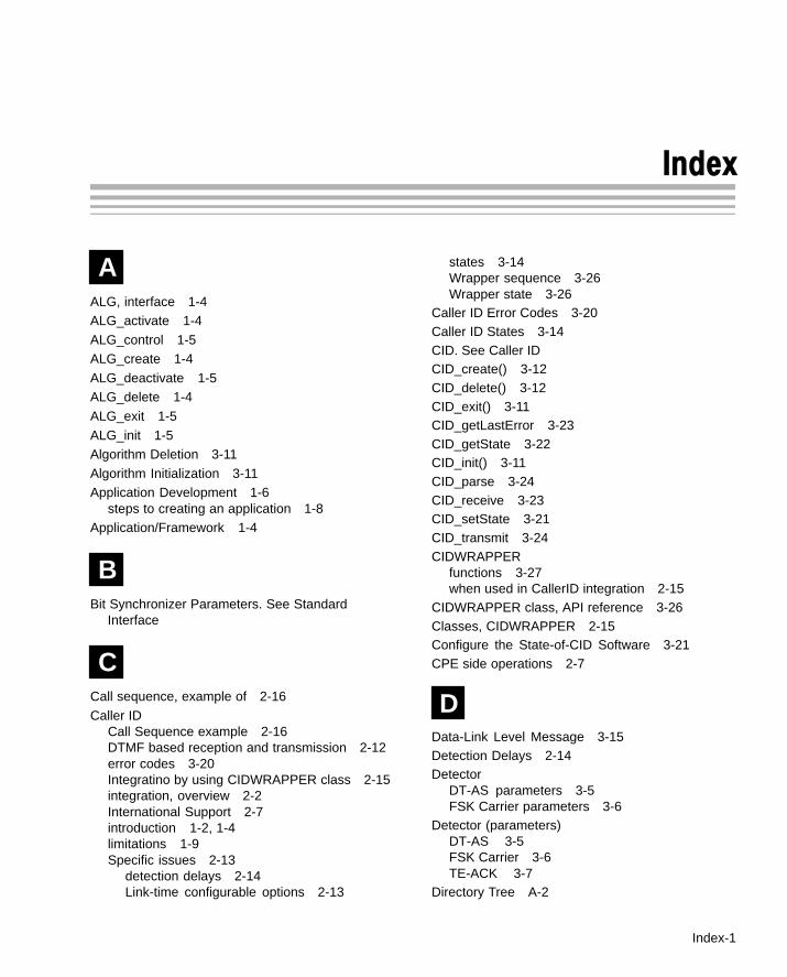
Index
Index-1
Index
AALG, interface 1-4ALG_activate 1-4
ALG_control 1-5ALG_create 1-4
ALG_deactivate 1-5ALG_delete 1-4
ALG_exit 1-5
ALG_init 1-5Algorithm Deletion 3-11
Algorithm Initialization 3-11Application Development 1-6
steps to creating an application 1-8Application/Framework 1-4
BBit Synchronizer Parameters. See Standard
Interface
CCall sequence, example of 2-16
Caller IDCall Sequence example 2-16DTMF based reception and transmission 2-12error codes 3-20Integratino by using CIDWRAPPER class 2-15integration, overview 2-2International Support 2-7introduction 1-2, 1-4limitations 1-9Specific issues 2-13
detection delays 2-14Link-time configurable options 2-13
states 3-14Wrapper sequence 3-26Wrapper state 3-26
Caller ID Error Codes 3-20Caller ID States 3-14CID. See Caller IDCID_create() 3-12CID_delete() 3-12CID_exit() 3-11CID_getLastError 3-23CID_getState 3-22CID_init() 3-11CID_parse 3-24CID_receive 3-23CID_setState 3-21CID_transmit 3-24CIDWRAPPER
functions 3-27when used in CallerID integration 2-15
CIDWRAPPER class, API reference 3-26Classes, CIDWRAPPER 2-15Configure the State-of-CID Software 3-21CPE side operations 2-7
DData-Link Level Message 3-15Detection Delays 2-14Detector
DT-AS parameters 3-5FSK Carrier parameters 3-6
Detector (parameters)DT-AS 3-5FSK Carrier 3-6TE-ACK 3-7
Directory Tree A-2

Index
Index-2
DT-ASDetector paramters 3-5Generator paramters 3-7
DT-AS Detector Parameters. See StandardInterface
DT-AS Generator Parameters. See StandardInterface
DTMFDecoder parameters 3-9Encoder parameters 3-9
DTMF Decoder parameters. See Standard Interface
DTMF Encoder parameters. See Standard Interface
DTMF-Based CallerID Reception andTransmission 2-12
EEnvironment, for testing A-2
FFramework 1-4
framework, integration flow 2-4
FSKCarrier Detector parameters 3-6Generator parameters 3-8
FSK Carrier Detector Parameters. See StandardInterface
FSK Generator parameters. See Standard Interface
FunctionsCIDWRAPPER 3-27Standard 3-11Vendor-specific 3-21
GGenerator (parameters)
DT-AS 3-7FSK 3-8
Get Current State of CID 3-22
Get Error Code 3-23
HHeader file
for abstract interfaces 1-6for concrete interfaces 1-5
IIALG 1-6Instance Creation 3-12Instance Creation Parameters. See Standard
InterfaceInstance Deletion 3-12Integration
by using CIDWRAPPER class 2-15operations
CPE side 2-7Local exchange side 2-10
overview 2-2Integration flow, steps to completing 2-4Interface 1-5
abstract 1-6concrete 1-5vendor implementation 1-6Vendor-specific 3-13
structures 3-13International Support, for Caller ID 2-7
Llimitations, for Caller ID 1-9Link-T ime Configurable Options 2-13, 3-4Local Exchange side operations 2-10
MMessage
Data-Link Level 3-15Presentation Level 3-16
Module Instance Lifetime. See ApplicationDevelopment
Ooperations
CPE side 2-7

Index
Index-3
Local exhchange side 2-10
PParameters
Bit Synchronizer 3-6DT-AS Detector 3-5DT-AS Generator 3-7DTMF Decoder 3-9DTMF Encoder 3-9FSK Carrier Detctor 3-6FSK Generator 3-8instance creation 3-3Russian Caller ID 3-10SAS signal 3-4TE-ACK detector 3-7TE_ACK Signal 3-5
Parse Data-link and Presentation Level Messages3-24
Presentation Level Message 3-16Process Samples to be Received 3-23Process Samples to be Transmitted 3-24
RReception, DTMF-based 2-12Russian Caller ID parameters. See Standard
Interface
SSAS Signal Parameters 3-4Signal (parameters)
SAS 3-4TE-ACK 3-5
Source filefor abstract interfaces 1-6
for concrete interfaces 1-5Standard Interface, structures 3-2Structures
Caller ID Error Codes 3-20Caller ID States 3-14Data-link Level Message 3-15Presentation Level Message 3-16standard interface 3-2vendor-specific 3-13
TTE-ACK
detector parameters 3-7Signal parameters 3-5
TE-ACK detector Parameters. See StandardInterface
TE-ACK Signal Parameters. See Standard InterfaceTest
files A-2format A-2project A-3
Test Environment A-2Transmition, DTMF-based 2-12
VVendor-Specific Interface 3-13
XXDAIS
Application Development 1-6Application/Framework 1-4Interface 1-5related documentaion 1-2System Layers, illustration of 1-4