Calibration of Sensors for Angular Vibration...
29
Calibration of Sensors for Angular Vibration Measurements VSB – Technical University of Ostrava Faculty of Mechanical Engineering Ostrava, Czech Republic Lubomir Smutny, Jiri Tuma, Radim Farana IMEKO XVIII Word Congress, Rio de Janeiro, RJ, Brazil September 16 – 22, 2006
Transcript of Calibration of Sensors for Angular Vibration...

Calibration of Sensors for Angular Vibration MeasurementsVSB – Technical University of Ostrava Faculty of Mechanical Engineering Ostrava, Czech Republic
Lubomir Smutny, Jiri Tuma, Radim Farana
IMEKO XVIII Word Congress, Rio de Janeiro, RJ, BrazilSeptember 16 – 22, 2006

© VSB-TU Ostrava, 2006 2
Outline
MotivationCalibration problemPrinciple of phase demodulation using Hilbert transformCalibration procedureSoftware tools for phase demodulationConclusion

© VSB-TU Ostrava, 2006 3
Motivation
Angular vibration as one of the important machine vibration and noise source.
Emitted gearbox noise level is proportional to the transmission error (TE) level resulting from the gear angular vibration.
Low noise gear design …

© VSB-TU Ostrava, 2006 4
Transducers & Signal Processing Methods for Angular Vibration Measurements
Tangentially mounted accelerometersLaser Torsional Vibration Meter (Doppler effect)Incremental rotary encoders(several hundreds of pulses per revolution)
Time interval length measurements
Sample number & InterpolationHigh frequency oscillator (10 GHz) & Impulse counter (Rotec)
Phase demodulation
Transducers How to process impulse signals

© VSB-TU Ostrava, 2006 5
Test Stand for Transmission Error (TE) Measurements
Back-to-back test rig
Simple gear train, tooth numbers n1, n2
Two incremental rotary encoders
PinionWheel
211
22 r
nnTE ⎟⎟
⎠
⎞⎜⎜⎝
⎛Θ−Θ=
2Θ1Θ
r2
Measurement range: ± 10 µm (microns)

© VSB-TU Ostrava, 2006 6
Calibration problem
Rotational speed up to 6000 RPMSampling frequency less than 65 kHz (or 256 kHz)Low price encoders (IRC)Easy to use, measurements in situ
Requirements for Measurements
Phase demodulation of impulse signals is reliable to useBoth the encoders for TE measurements are enough accurate
It was needed to prove that
© VSB-TU Ostrava, 2006 7
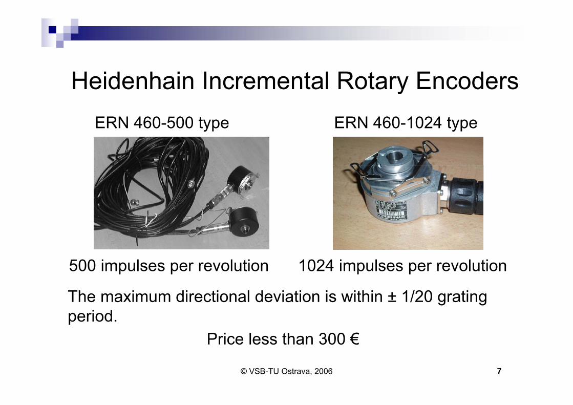
Heidenhain Incremental Rotary Encoders
500 impulses per revolution 1024 impulses per revolution
Price less than 300 €
ERN 460-500 type ERN 460-1024 type
The maximum directional deviation is within ± 1/20 grating period.

© VSB-TU Ostrava, 2006 8
Laser Torsional Vibration MeterDual-beam laser transducer based on the Doppler effectLaser: Ga-Al-As diode producing 780 nm lightOutput: instantaneous changes in angular velocityMeasurement ranges:10, 100, 1000, 100000/s Frequency range: 0.3 to 1000 Hz Accuracy: ±1% of full scale Brüel & Kjær Type 2523
© VSB-TU Ostrava, 2006 9
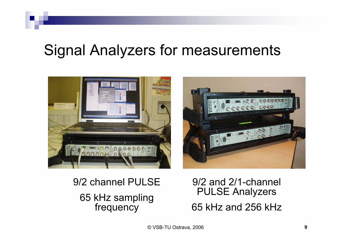
Signal Analyzers for measurements
9/2 channel PULSE65 kHz sampling
frequency
9/2 and 2/1-channel PULSE Analyzers
65 kHz and 256 kHz

© VSB-TU Ostrava, 2006 10
Principle of Phase Demodulation
-1,5-1,0-0,50,00,51,01,5
0,0 0,2 0,4 0,6 0,8 1,0Time [s]
yi
How to evaluate the instantaneous phase of the harmonic signal?
Instantaneous envelope Ei = ?( )iii Eyarcsin=ϕ

© VSB-TU Ostrava, 2006 11
Phase Modulation
Real phase modulated signal
Pω
-2,0-1,00,01,02,0
0 0,1 0,2 0,3 0,4 0,5 0,6 0,7 0,8 0,9 1
Nominal Revolution
x(t) = A cos(ωPt+∆φM(t))
PhaseModulation signal Sideband
components
Carrying component
Analytic signal

© VSB-TU Ostrava, 2006 12
Phase demodulation based on the Hilbert transform
Using FFT and Inverse FFT
Using digital filters as the Hilbert transformer
2π
2π Hilbert
Transformer
x(t)x(t)
y(t)
Real part
Imaginary part
( ) ( ){ }kxFFTjX =ω
( ) ( ){ }ω= jYIFFTky
Impulse Response
-1,0-0,50,00,51,0
-16 -12 -8 -4 0 4 8 12 16Index n

© VSB-TU Ostrava, 2006 13
( )πϕ ≤∆⇒≤ samplff2
-4-2024
0 0,1 0,2 0,3 0,4 0,5 0,6 0,7 0,8 0,9 1
Nominal Revolution
rad
Phase Unwrapping and Linear Trend Removing
-0,15-0,10-0,050,000,050,100,15
0 0,2 0,4 0,6 0,8 1
Nominal Revolution
rad
02468
0 0,2 0,4 0,6 0,8 1
Nominal Revolution
rad
Discontinuities removing
π−
π+
π2
ϕ→π−ϕ⇒π+>ϕ∆ϕ→π+ϕ⇒π−<ϕ∆ 2,2

© VSB-TU Ostrava, 2006 14
Calibration Procedure
Verifying the method of the phase demodulation by comparing simultaneous encoder and laser angular vibration measurementsComparing of two identical encoders mounted on the common shaft

© VSB-TU Ostrava, 2006 15
Comparison of Laser and Encoder Angular Velocity Measurements
Laser
Encoder
1188 RPM
-20246
0,0000 0,0005 0,0010Time [s]
V-80-60-40-20
020
15000 17500 20000 22500 25000Frequency [Hz]
RM
S dB
/ref 1
V
Impulse signal 65536 Smps/s
Frequency spectrum

© VSB-TU Ostrava, 2006 16
Differentiation with Respect to TimeImpulse Response : Ideal Diff FIR Filter
-150-100-50
050
100150
0,0000 0,0005 0,0010 0,0015 0,0020Time [s]
gi
Phase demodulation
Differentiation with respect to time
Impulse signal
Phase (Angle)
Angular velocity
Frequency Response : Ideal Diff FIR Filter
20304050607080
10 100 1000 10000Frequency [Hz]
Mag
nitu
de in
dB

© VSB-TU Ostrava, 2006 17
Averaged Time Signal and Frequency Spectrum
-20
-10
0
10
20
30
40
50
60
0 50 100 150
Order [-]R
MS
dB/re
f 1 d
eg/s
Encoder Laser
-200-100
0100200
0,0 0,2 0,4 0,6 0,8 1,0Nominal Revolution [-]
Ang
ular
vel
ocity
[deg
/s]
-200-100
0100200
0,00 0,02 0,04 0,06 0,08 0,10Nominal Revolution [-]
Ang
ular
vel
ocity
[deg
/s]
Laser Encoder

© VSB-TU Ostrava, 2006 18
Comparison of two encoders of the ERN 460-500 type
-2024
0,0000 0,0005 0,0010 0,0015 0,0020Time [s]
Volt E1
E2
E1E2 500 impulses per revolution
Autospectrum
-100-80-60-40-20
0
300 400 500 600 700
Order [-]
RM
S dB
/ref 1
E1E2
© VSB-TU Ostrava, 2006 19
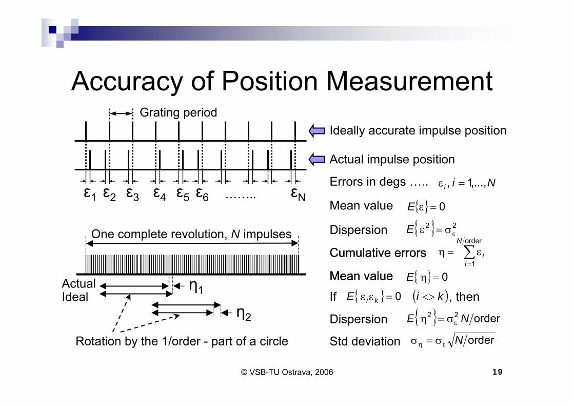
Accuracy of Position Measurement
ε1 ε2 ε3 ε4 ε5 ε6 εN
Ideally accurate impulse position
Actual impulse position
Errors in degs …..
One complete revolution, N impulses
η1
η2
ActualIdeal
Rotation by the 1/order - part of a circle
Mean value { } 0=εE
Dispersion { } 22εσ=εE
Mean value { } 0=ηE
Dispersion { } order22 NE εσ=η
∑=
ε=ηorder
1
N
ii
Nii ,...,1, =ε
Cumulative errors
……..
Std deviation orderNεη σ=σ
Grating period
Mean value
Cumulative errors
If , then{ } ( )kiE ki <>=εε 0

© VSB-TU Ostrava, 2006 20
Phase Difference between Two Encoders of the ERN 460-500 Type
E1E2
Phase difference
0,000001
0,000010
0,000100
0,001000
0,010000
0,100000
1,000000
1 10 100 1000Order [-]
RM
S de
g 634 RPM1040 RPM
Phase difference
-0,04
-0,03
-0,02
-0,01
0,00
0,01
0,02
0,03
0,04
0,0 0,2 0,4 0,6 0,8 1,0
Nominal Revolution [-]
deg
Maximum directional deviation
Uncorrelated errors

© VSB-TU Ostrava, 2006 21
Indoor Software Tools for Angular Vibration Measurements
© VSB-TU Ostrava, 2006 22
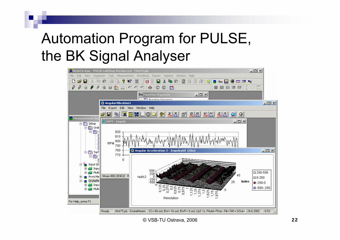
Automation Program for PULSE, the BK Signal Analyser

© VSB-TU Ostrava, 2006 23
Signal Analyser

© VSB-TU Ostrava, 2006 24
ConclusionThe paper is focused on the calibration of the angular vibration sensorsThere are many approaches to angular vibration measurements, e.g. laser vibrometers, encodersPhase demodulation based on the theory of analytical signals gives reliable result of measurementsThe low impulse number encoders seem to be more accurate at the 1/20-part of a circle than the maximum directional error stated in the Heidenhain brochureThe theory is illustrated by the verification and comparison of the encoders.
© VSB-TU Ostrava, 2006 25
Thank you for your attention

© VSB-TU Ostrava, 2006 26
Measurement Examples

© VSB-TU Ostrava, 2006 27
Effect of Phase Modulation on Impulse Signal Frequency Spectrum
Pinion 21 T Wheel 44 TEnhanced Spectrum , 21-Tooth Gear
-90-80-70-60-50-40-30-20-10
010
395 416 437 458 479 500 521 542 563 584 605
Order [-]
RM
S dB
/ref 1
V
Enhanced Spectrum , 44-Tooth Gear
-90-80-70-60-50-40-30-20-10
010
324 368 412 456 500 544 588 632 676
Order [-]R
MS
dB/re
f 1 V
Scaled in multiples of the rotational frequency
Carrying component
Sidebands

© VSB-TU Ostrava, 2006 28
Angular Vibration of the 21and 44-Tooth Gear in Degs (after Comb Filtration)
Toothmeshing frequency harmonics with some sideband components
Time History : Pinion 21T : Enhanced Time(Impulsy500)
-0,002-0,0010,0000,0010,002
0,0 0,1 0,2 0,3 0,4 0,5 0,6 0,7 0,8 0,9 1,0
deg
Time History : Wheel 44T : Enhanced Time(Impulsy500)
-0,006-0,0030,0000,0030,006
0,0 0,2 0,4 0,6 0,8 1,0Nominal Revolution [-]
deg

© VSB-TU Ostrava, 2006 29
An Alternative Procedure
( ) ( )( ) ( ) ( ) ( )
( ) ( )tytxdt
tdytxtydt
tdx
dttdt 22 +
−=
ϕ=ω
( ) ( )( ) ⎟⎟⎠
⎞⎜⎜⎝
⎛=ϕ
txtyt arctan
( ) ( ) ( )tytxtE 22 +=
Phase ……………....
Angular frequency ...
Envelope ..………….
( ) ( ) τ∫ τω=ϕ dtt
0
Phase ……………….