Caleb Adams, Jackson Parker Computational Imager (MOCI ...
40
Selected Software Demonstrations from the Multi-view Onboard Computational Imager (MOCI) Satellite Caleb Adams, Jackson Parker
Transcript of Caleb Adams, Jackson Parker Computational Imager (MOCI ...

Selected Software Demonstrations from the Multi-view Onboard Computational Imager (MOCI) Satellite
Caleb Adams, Jackson Parker
Presentation Expectations• “Selected” demonstrations
• Overview of Concepts
• Hot swapping between machines to show the demos

MOCI: Multi-view Onboard Computational Imager
● Part of the 9th University Nanosatellite Program
● 9 winners since 1998 (MIT, GT, UC Boulder, … and us!)
● Competed against 9 schools for a chance to fully build and launch
○ UGA WON!
○ UGA was the first team without an aerospace department
○ First team to win on first try
● Launch in late 2020
3
We move quickly so many designs that
make it to diagrams are out of date,
we’re actually twice as big now ->

MOCI: Multi-view Onboard Computational Imager
● Will produce 3D models of the Earth's surface from space
● Use computer vision to track objects on the surface
● Use neural networks to identify surface targets
Simulation of the tracking of objects over the red sea from an ISS nadir video.
The UGA SSRL’s miniaturized high performance computation unit developed around the Nvidia TX2i for
the MOCI satellite Simulated computations of mountain ranges
4

MOCI Hardware● Required to be extremely computationally
capable
● No existing space technology can satisfy our requirements. So we’re building high-performance space systems.
● We’re transitioning terrestrial high-performance embedded systems into space
○ From autonomous cars
○ From AI-optimized processors
5
The UGA SSRL’s miniaturized high performance computation unit developed around the Nvidia TX2i for
the MOCI satellite
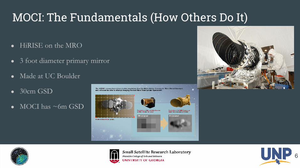
MOCI: The Fundamentals (How Others Do It)
● HiRISE on the MRO
● 3 foot diameter primary mirror
● Made at UC Boulder
● 30cm GSD
● MOCI has ~6m GSD
6

MOCI: The Fundamentals (How Others Do It)
● MRO, at Mars, is the most similar large satellite to MOCI
● Multi-view geometry (parallax) used to deduce topography
● Doesn’t seem so hard right?
7

Multiview Reconstruction
● Changing camera parameters (extrinsic and intrinsic)
○ Thermal, inertia, optical …
● Uncertain pose
● Stereo disparity results in poor fidelity models
● Sub-pixel resolution
8

Optical Design● Made for orbital multiview reconstruction, need
to be custom made each time! (no COTS)
● Bounding our unknowns
● HiRISE
● Our optical design also prioritizes high resolution
● Specs: 90/10 beam splitter, ~4K BW CMOS, ~1K RGB CMOS, 280 mm effective focal length
9
Current MOCI optical layout

Camera Matrices • Assumption of pinhole
• Simple projection model

Concept: Features
● Stereo multiview produces poor matches
● Features can be used for better matching
● What makes a good feature?
● In remote sensing features are sometimes called “Tie Points”
11
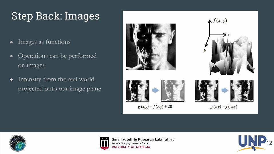
Step Back: Images
● Images as functions
● Operations can be performed on images
● Intensity from the real world projected onto our image plane
12

Reminder: Discrete Convolution
● “Filter” the image with a gaussian function
● Gaussian convolution is a better “blur” or “smoothing” of the image function
● Convolved with a “kernel”
13
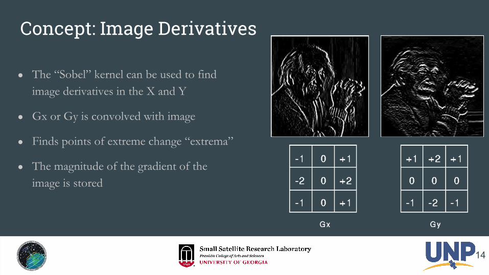
Concept: Image Derivatives
● The “Sobel” kernel can be used to find image derivatives in the X and Y
● Gx or Gy is convolved with image
● Finds points of extreme change “extrema”
● The magnitude of the gradient of the image is stored
14

Concept: Scale Space
● A formal theory describing image structures at differing scales…
● Convolving images with gaussians of different sigma
● Similar effect to changing pixel sizes, resolution, GSD, focal length, etc …
15
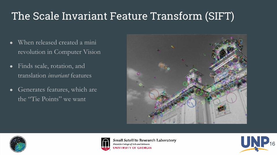
The Scale Invariant Feature Transform (SIFT)
● When released created a mini revolution in Computer Vision
● Finds scale, rotation, and translation invariant features
● Generates features, which are the “Tie Points” we want
16

SIFT - how it works (briefly)
● Convolves Gaussian kernel with images while varying sigma
● Creates multiscale Gaussian pyramid
● Approximates a Laplacian of Gaussians (LoG) with a Difference of Gaussians (DoG)
● Detected extrema are stable features locations in scale space
17

SIFT - how it works (briefly)
● Around each detected extrema, calculate a Histogram of Oriented Gradients (HoG)
● Rotate the HoG to the greatest histogram bin
● HoG is used as a feature descriptor
18

SIFT - how it works (briefly)
● Matching features is done by comparing the HoG of features
● Minimum Euclidean distance
● Min difference between the 128 feature vectors
19

Demo - Standard SIFT
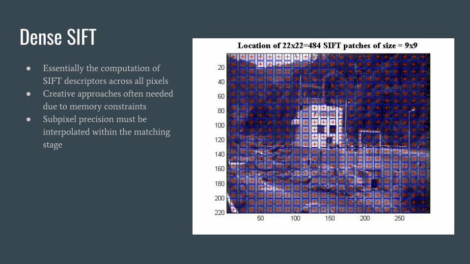
Dense SIFT ● Essentially the computation of
SIFT descriptors across all pixels
● Creative approaches often needed
due to memory constraints
● Subpixel precision must be
interpolated within the matching
stage

Demo - Dense SIFT

Optical Flow● Each Frame:
○ Feature locations determined
○ Feature descriptors calculated
● Track Objects
● A single step in Structure from Motion
demo - Optical Flow

Triangulation● Skew lines are practically
guaranteed. An estimated point is generated at closest approach with least squares.
● Reprojection Error: The distance between the estimated point projection and the feature location
● Errors in projection and feature detection must be accounted for
25

demo - Triangulation
● 2 view discussion
○ 2-view Least Squares
○ 2-view skew line
● 2-view Least Squares demo
● n-view discussion

Bundle Adjustment● We seek to minimize the
reprojection error
● Consider the relationship between all variables
● Generate massive matrix to optimize
● Final step to generate 3D model cloud (sort of)
● Very difficult to compute
27

Solving Bundle Adjustment
● Large matrix optimization problem
● Gauss-Newton methods are typically used. The cost function is the reprojection error.
● Levenberg–Marquardt algorithm is current best general approach
● Jacobians and Hessians over a massive matrix… this is why we need a GPU in space!
28

MOCI Simulations
● We test our algorithms with simulations
● Realistic 3D models
● GPUs are needed
● Decent results so far!
29
image acquisitionpoint cloud generation
surface reconstructionGeoTiff Generation (Rasterization)

demo - Blender Simulations
30

Surface Reconstruction - Overview
● Octree Generation
● Normal Determination
● Poisson Surface Reconstruction
○ Indicator Function Determination
○ Marching Cubes
31

The Octree
● Built on GPU - can be used on CPU or GPU
● Nodes
○ Pointer to contained points
○ Children, Neighbor and Parent pointers
○ Vertices, Edge and Face pointers
● Non redundant Vertice, Edge and Face Arrays
32
MAJOR STEPS
1. Build nodes around points 2. Fill in missing siblings and
generate parents3. Neighborhood determination 4. Vertex, Edge and Face generation

demo - The Octree
33

Point Normal Calculations● Find K nearest Points ● Calculate centroid● Build matrix Mi,k = {q ∈ Qi,k| q - m}● Singular Value Decomposition (SVD) on
covariance matrix MTM● Normal = Last eigenvector (row in VT)
○ orthogonal to neighbor plane● Eliminate directional ambiguity
○ if direction is ambiguous relative to camera positions and normals of neighbors n *= {-1,-1,-1}
34

demo - Point Normal Caclulations
35
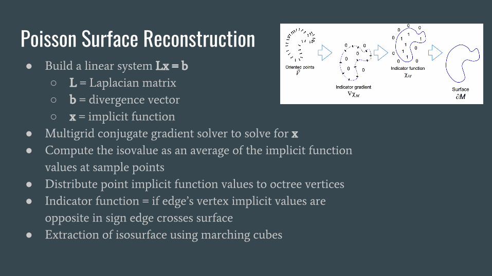
Poisson Surface Reconstruction● Build a linear system Lx = b
○ L = Laplacian matrix
○ b = divergence vector
○ x = implicit function
● Multigrid conjugate gradient solver to solve for x
● Compute the isovalue as an average of the implicit function
values at sample points
● Distribute point implicit function values to octree vertices
● Indicator function = if edge’s vertex implicit values are
opposite in sign edge crosses surface
● Extraction of isosurface using marching cubes
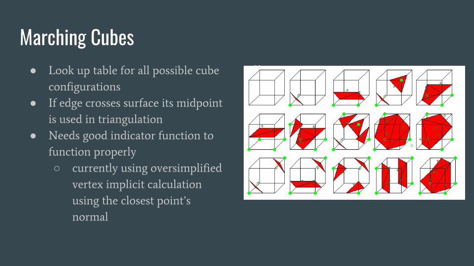
Marching Cubes● Look up table for all possible cube
configurations
● If edge crosses surface its midpoint
is used in triangulation
● Needs good indicator function to
function properly
○ currently using oversimplified
vertex implicit calculation
using the closest point’s
normal
V

demo- Marching Cubes

What’s next?● n-view matching● bundle adjustment● poisson reconstruction

MOCIQuestions?smallsat.uga.eduUniversity of Georgia