CALCULATIONS / EVALUATIONS - West Virginia VOLTAGE CALCULATION.pdfCALCULATIONS / EVALUATIONS West...
17
HIGH VOLTAGE CALCULATIONS / EVALUATIONS West Virginia Office of Miners’ Health, Safety & Training Helping You To Work More Safely In The Mining Industry
Transcript of CALCULATIONS / EVALUATIONS - West Virginia VOLTAGE CALCULATION.pdfCALCULATIONS / EVALUATIONS West...

HIGH VOLTAGE
CALCULATIONS / EVALUATIONS
West Virginia Office of Miners’ Health, Safety
& Training
Helping You To Work More Safely In The
Mining Industry

DISCLAIMER
The West Virginia Office of Miners’ Health, Safety and Training publishes this booklet. The material should be used by mine electricians to assist in selecting the proper protective settings for over current, short circuit, and ground fault protection. The material is not all-inclusive and should be used only as an aide in gaining compliance with the regulations. This material is based upon several different publications including West Virginia State Mining Regulations, The National Electrical Code, Title 30 CFR, and the Program Policy Manual. Only two manufacturers of high voltage over current relays are listed; however, products of other manufacturers can easily be cross-referenced to those listed. Nothing herein should be construed as recommending any manufacturer’s products.
Visit our website
www.wvminesafety.org

West Virginia Office of Miners’ Health, Safety and Training Doug Conway Director C.A. Phillips Deputy Director Gerry Barton Benny Comer Danny Cook Don Crawford Tom Harmon John Scott Kendall Smith Randy Smith Bobby Thornsbury Electrical Inspectors Mine Safety and Health Administration District 4 Larry Cook Supervisor Electrical Engineer Marcus Smith Electrical Engineer National Mine Health and Safety Academy Sandy Neal Graphic Arts
INSTANTANEOUS
UNIT ADJUSTABLE CORE
TAP SELECTOR BLOCK
TAP PLUG
TIME DIAL
CONTROL SPRING
ADJUSTING RING
INSTANTANEOUSUNIT
DISK

Direct Relaying. In this method, grounded-phase current is detected directly with a current transformer installed in the grounded neutral conductor.
Balance Flux Relaying. In this method, grounded-phase current is detected by a doughnut-type current transformer installed around the three phase conductors. Note: The equipment grounding conductors (including conductor shields) must not be installed through the current transformer.
Residual Trip Relaying. In this method, grounded-phase current is detected as the unbalance in the current produced by the phase current transformers.
Potential Relaying. In this method, grounded-phase current is detected as the voltage drop across the grounding resistor. An advantage of this method over the three previous methods is that grounded-phase protection is still provided even if the grounding resistor is open. For this reason, potential relaying is often used to provide backup grounded-phase protection for resistance-grounded systems.
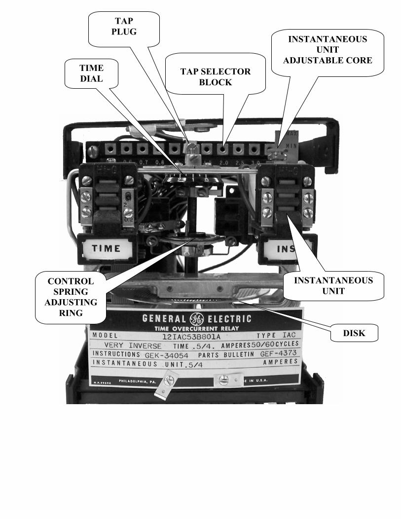
OVERCURRENT RELAY 4160 volt system phase to phase 2/0 AWG cable 5 KV rating at 90 degree insulation Cable rated for 287 amps X 125% = 359 amps Current transformer ratio 80:1 Tap bar range 2.0 to 16 80:1 X tap 4 = 320 amps SHORT CIRCUIT Using a breaker, the short circuit is set no greater than 600% X cable ampacity of 287 amps. (287 X 6 = 1722 amps) This setting is achieved by adjusting the instantaneous unit adjustable core screw. GROUND FAULT 4160 volts phase to phase 2400 volts phase to neutral 25 amp grounding resistor 96 ohms Tap bar range 0.5 to 2.0 Ground fault current is set at no more than 50% of the amp rating of the resistor Current transformer ratio is 10:1 Current transformer ratio 10:1 set on tap 1.2 (10 X 1.2 = 12 amps) which is less than 50% of the 25 amp grounding resistor.
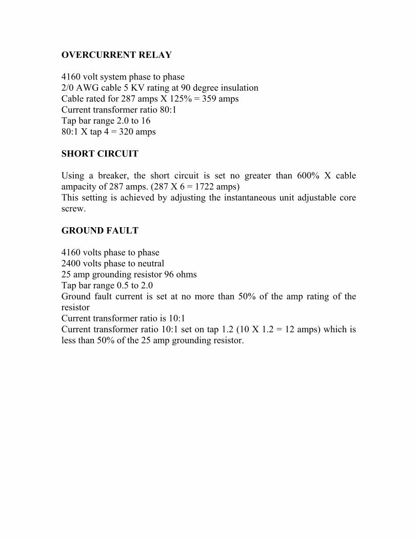
4160 volt system phase to phase 2001 - 8000 VOLTS 8001 - 15000 VOLTS 2/0 AWG cable 5KV volt rating 90c insulation AWG 75c 85c 90c AWG 75c 85c 90c Current Transformer 50:1 ratio 2 170 182 188 2 168 187 194 25 amp grounding resistor rated at 96 ohms X125% 213 228 235 X125% 210 234 243 Current tap block 2 - 16 amps. X600% 1020 1092 1128 X600% 1008 1122 1164 Instantaneous unit adjustable from 20-40 amps 1 196 210 217 1 192 215 221
X125% 245 263 271 X125% 240 268 276TAPS RATIO X600% 1176 1260 1302 X600% 1152 1290 1326
A O 1 O 51-1 BC 10/1 1/0 226 242 249 1/0 221 247 254B O 2 O AB 20/1 X125% 283 303 311 X125% 276 309 318C O 3 O AC 30/1 X600% 1356 1452 1494 X600% 1326 1482 1524D O 4 O DE 40/1 2/0 260 278 287 2/0 253 282 290E O 5 O CD 50/1 X125% 325 348 359 X125% 316 353 363G O 6 O BD 60/1 X600% 1560 1668 1722 X600% 1518 1692 1740
AD 80/1 3/0 299 320 329 3/0 290 324 334A O 1 O 51-2 CE 90/1 X125% 374 400 411 X125% 363 405 418B O 2 O BE 100/1 X600% 1794 1920 1974 X600% 1740 1944 2004C O 3 O AE 120/1 4/0 343 367 379 4/0 333 372 384D O 4 O X125% 429 459 474 X125% 416 465 480E O 5 O X600% 2058 2202 2274 X600% 1998 2232 2304G O 6 O
TIME OVERCURRENT RELAYA O 1 O 51-3 MODEL 000000000000 TYPE I A C B O 2 O G INVERSE TIME 2 - 16 AMPERES 60 CYCLESC O 3 O r INSTRUCTIONS 00000000 PARTS BULLETIND O 4 O o INSTANTANEOUS UNIT 20 - 40 AMPERESE O 5 O uG O 6 O n Current Tap Block
d O O O O O O O O O O O2 3 4 5 6 7 8 10 12 14 16
Instantaneous Unit Pickup Adjustment
40 MAX ___ 20 MIN.
OVERCURRENT & SHORT CIRCUIT PROTECTIONO O
Cable ampacity 287 amps X 125% = 359. Set the taps on O O A and D on the multi-tap CT to obtain a 80:1 ratio. O O Which tap on the multi-tap block would be used to obtain the highest allowable setting for the 2/0 AWG cable? 4 What is the actual ampacity set at? 320 Set the short circuit instantaneous unit on the maximum allowable 1722 amps. Set the instantaneous unit core at 21.5 amps. ( 1722 Divided by 80:1 CT Ratio - 21.5)
Ground Fault Tap Blocko o o o o o o o o o o 10:1 Ratio
0.5 0.6 0.7 0.8 0.9 1 1.2 1.4 1.6 1.8 2
Which tap on the multi-tap block would be used to
obtain the highest allowable setting? 1.2
What is the actual setting? 12 amps.
Cable Ampacity 287 X 6 = 1722 Max.SC
1722 Divided by 80:1 CT Ratio = 21.5 Amps Max.
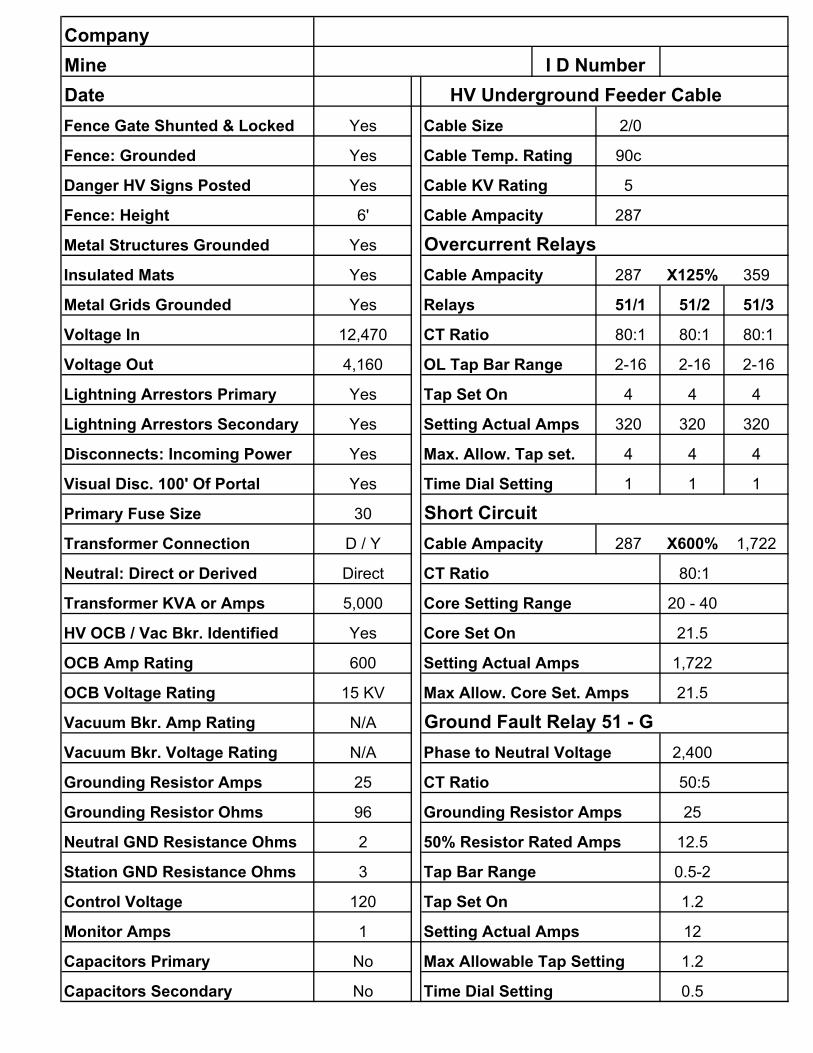
CompanyMine I D NumberDate HV Underground Feeder CableFence Gate Shunted & Locked Yes Cable Size 2/0
Fence: Grounded Yes Cable Temp. Rating 90c
Danger HV Signs Posted Yes Cable KV Rating 5
Fence: Height 6' Cable Ampacity 287
Metal Structures Grounded Yes Overcurrent RelaysInsulated Mats Yes Cable Ampacity 287 X125% 359
Metal Grids Grounded Yes Relays 51/1 51/2 51/3
Voltage In 12,470 CT Ratio 80:1 80:1 80:1
Voltage Out 4,160 OL Tap Bar Range 2-16 2-16 2-16
Lightning Arrestors Primary Yes Tap Set On 4 4 4
Lightning Arrestors Secondary Yes Setting Actual Amps 320 320 320
Disconnects: Incoming Power Yes Max. Allow. Tap set. 4 4 4
Visual Disc. 100' Of Portal Yes Time Dial Setting 1 1 1
Primary Fuse Size 30 Short CircuitTransformer Connection D / Y Cable Ampacity 287 X600% 1,722
Neutral: Direct or Derived Direct CT Ratio 80:1
Transformer KVA or Amps 5,000 Core Setting Range 20 - 40
HV OCB / Vac Bkr. Identified Yes Core Set On 21.5
OCB Amp Rating 600 Setting Actual Amps 1,722
OCB Voltage Rating 15 KV Max Allow. Core Set. Amps 21.5
Vacuum Bkr. Amp Rating N/A Ground Fault Relay 51 - GVacuum Bkr. Voltage Rating N/A Phase to Neutral Voltage 2,400
Grounding Resistor Amps 25 CT Ratio 50:5
Grounding Resistor Ohms 96 Grounding Resistor Amps 25
Neutral GND Resistance Ohms 2 50% Resistor Rated Amps 12.5
Station GND Resistance Ohms 3 Tap Bar Range 0.5-2
Control Voltage 120 Tap Set On 1.2
Monitor Amps 1 Setting Actual Amps 12
Capacitors Primary No Max Allowable Tap Setting 1.2
Capacitors Secondary No Time Dial Setting 0.5
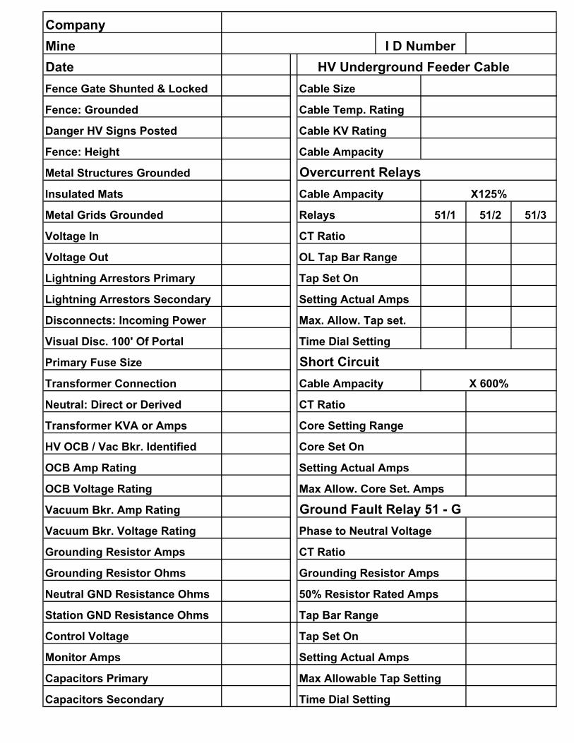
CompanyMine I D NumberDate HV Underground Feeder CableFence Gate Shunted & Locked Cable Size
Fence: Grounded Cable Temp. Rating
Danger HV Signs Posted Cable KV Rating
Fence: Height Cable Ampacity
Metal Structures Grounded Overcurrent RelaysInsulated Mats Cable Ampacity X125%
Metal Grids Grounded Relays 51/1 51/2 51/3
Voltage In CT Ratio
Voltage Out OL Tap Bar Range
Lightning Arrestors Primary Tap Set On
Lightning Arrestors Secondary Setting Actual Amps
Disconnects: Incoming Power Max. Allow. Tap set.
Visual Disc. 100' Of Portal Time Dial Setting
Primary Fuse Size Short CircuitTransformer Connection Cable Ampacity X 600%
Neutral: Direct or Derived CT Ratio
Transformer KVA or Amps Core Setting Range
HV OCB / Vac Bkr. Identified Core Set On
OCB Amp Rating Setting Actual Amps
OCB Voltage Rating Max Allow. Core Set. Amps
Vacuum Bkr. Amp Rating Ground Fault Relay 51 - GVacuum Bkr. Voltage Rating Phase to Neutral Voltage
Grounding Resistor Amps CT Ratio
Grounding Resistor Ohms Grounding Resistor Amps
Neutral GND Resistance Ohms 50% Resistor Rated Amps
Station GND Resistance Ohms Tap Bar Range
Control Voltage Tap Set On
Monitor Amps Setting Actual Amps
Capacitors Primary Max Allowable Tap Setting
Capacitors Secondary Time Dial Setting

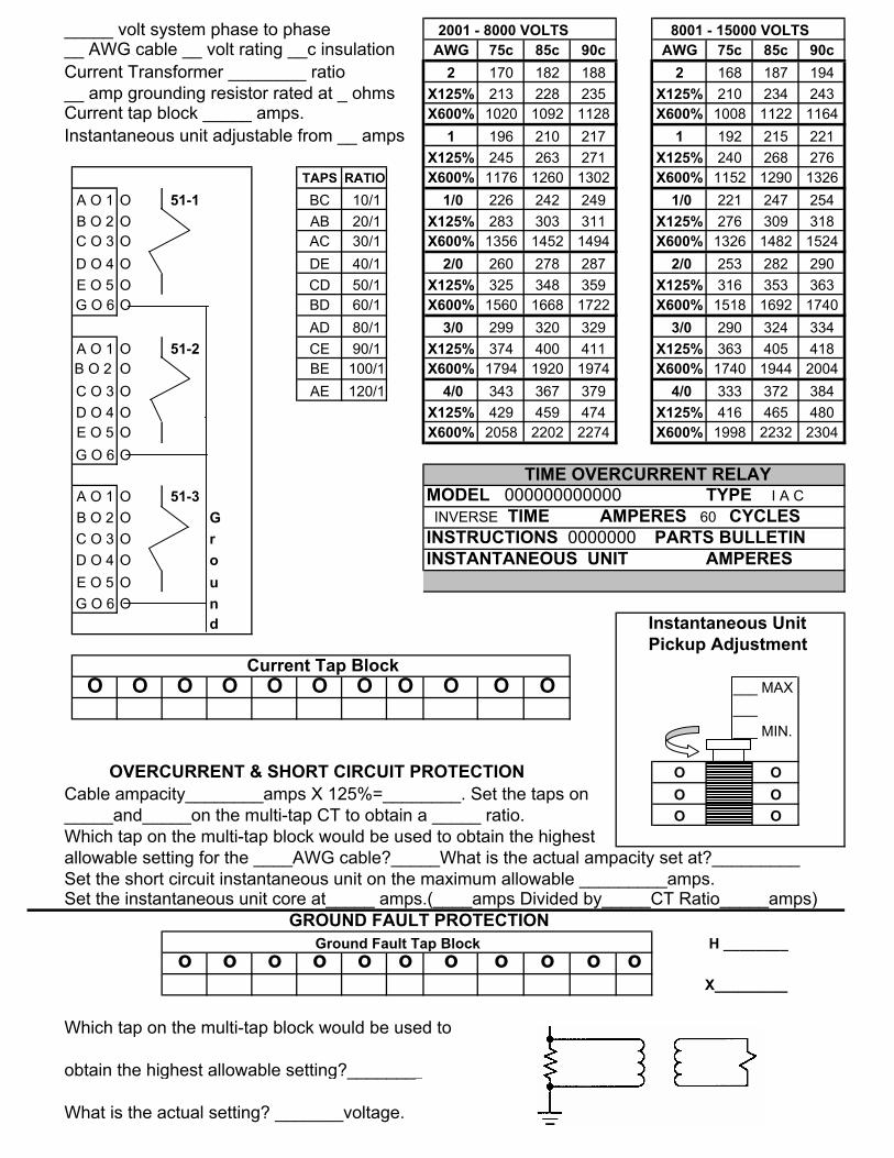
_____ volt system phase to phase 2001 - 8000 VOLTS 8001 - 15000 VOLTS ____ AWG cable __ volt rating __c insulation AWG 75c 85c 90c AWG 75c 85c 90c Current Transformer ________ ratio 2 170 182 188 2 168 187 194 ___ amp grounding resistor rated at __ ohms X125% 213 228 235 X125% 210 234 243 Current tap block ________ amps. X600% 1020 1092 1128 X600% 1008 1122 1164 Instantaneous unit adjustable from ____ amps 1 196 210 217 1 192 215 221
X125% 245 263 271 X125% 240 268 276TAPS RATIO X600% 1176 1260 1302 X600% 1152 1290 1326
A O 1 O 51-1 BC 10/1 1/0 226 242 249 1/0 221 247 254B O 2 O AB 20/1 X125% 283 303 311 X125% 276 309 318C O 3 O AC 30/1 X600% 1356 1452 1494 X600% 1326 1482 1524D O 4 O DE 40/1 2/0 260 278 287 2/0 253 282 290E O 5 O CD 50/1 X125% 325 348 359 X125% 316 353 363G O 6 O BD 60/1 X600% 1560 1668 1722 X600% 1518 1692 1740
AD 80/1 3/0 299 320 329 3/0 290 324 334A O 1 O 51-2 CE 90/1 X125% 374 400 411 X125% 363 405 418B O 2 O BE 100/1 X600% 1794 1920 1974 X600% 1740 1944 2004C O 3 O AE 120/1 4/0 343 367 379 4/0 333 372 384D O 4 O X125% 429 459 474 X125% 416 465 480E O 5 O X600% 2058 2202 2274 X600% 1998 2232 2304G O 6 O
TIME OVERCURRENT RELAYA O 1 O 51-3 MODEL 000000000000 TYPE I A C B O 2 O G INVERSE TIME AMPERES 60 CYCLESC O 3 O r INSTRUCTIONS 00000000 PARTS BULLETIND O 4 O o INSTANTANEOUS UNIT AMPERESE O 5 O uG O 6 O n Current Tap Block
d O O O O O O O O O O O
Instantaneous Unit Pickup Adjustment
___ MAX ___
OVERCURRENT & SHORT CIRCUIT PROTECTION ___ MIN.
O O Cable ampacity________amps X 125%=________. Set the taps on O O _____and_____on the multi-tap CT to obtain a _____ ratio. O O Which tap on the mult- tap block would be used to obtain the highest allowable setting for the ____AWG cable?_____What is the actual ampacity set at?_________ Set the short circuit instantaneous unit on the maximum allowable _______amps. Set the instantaneous unit core at_____ amps.(____amps Divided by_____CT Ratio_____amps)
GROUND FAULT PROTECTION Ground Fault Tap Block
o o o o o o o o o o o _______CT RATIO
Which tap on the multi-tap block would be used to obtain the highest allowable setting?__________ What is the actual setting? _______amps.

_____ volt system phase to phase 2001 - 8000 VOLTS 8001 - 15000 VOLTS ___ AWG cable ____ volt rating __c insulation AWG 75c 85c 90c AWG 75c 85c 90c Current Transformer ________ ratio 2 170 182 188 2 168 187 194 __ amp grounding resistor rated at____ ohms X125% 213 228 235 X125% 210 234 243 Current tap block ________ amps. X600% 1020 1092 1128 X600% 1008 1122 1164 Instantaneous unit adjustable from ___ amps 1 196 210 217 1 192 215 221
X125% 245 263 271 X125% 240 268 276TAPS RATIO X600% 1176 1260 1302 X600% 1152 1290 1326
A O 1 O 51-1 BC 10/1 1/0 226 242 249 1/0 221 247 254B O 2 O AB 20/1 X125% 283 303 311 X125% 276 309 318C O 3 O AC 30/1 X600% 1356 1452 1494 X600% 1326 1482 1524D O 4 O DE 40/1 2/0 260 278 287 2/0 253 282 290E O 5 O CD 50/1 X125% 325 348 359 X125% 316 353 363G O 6 O BD 60/1 X600% 1560 1668 1722 X600% 1518 1692 1740
AD 80/1 3/0 299 320 329 3/0 290 324 334A O 1 O 51-2 CE 90/1 X125% 374 400 411 X125% 363 405 418B O 2 O BE 100/1 X600% 1794 1920 1974 X600% 1740 1944 2004C O 3 O AE 120/1 4/0 343 367 379 4/0 333 372 384D O 4 O X125% 429 459 474 X125% 416 465 480E O 5 O X600% 2058 2202 2274 X600% 1998 2232 2304G O 6 O
TIME OVERCURRENT RELAYA O 1 O 51-3 MODEL 12IAC51B108A TYPE I A C B O 2 O G INVERSE TIME AMPERES 60 CYCLESC O 3 O r INSTRUCTIONS GEH-1753 PARTS BULLETIND O 4 O o INSTANTANEOUS UNIT AMPERESE O 5 O uG O 6 O n
d Instantaneous Unit
Current Tap Block Pickup AdjustmentO O O O O O O O O O O
___ MAX ___ ___ MIN.
OVERCURRENT & SHORT CIRCUIT PROTECTION O O Cable ampacity_______amps X 125%=______. Set the taps on O O _____and_____on the multi-tap CT to obtain a _____ ratio. O O Which tap on the mult-tap block would be used to obtain the highest allowable setting for the ____AWG cable?_____What is the actual ampacity set at?_________ Set the short circuit instantaneous unit on the maximum allowable _________amps. Set the instantaneous unit core at_____ amps.(____amps Divided by_____CT Ratio_____amps)
GROUND FAULT PROTECTION Ground Fault Tap Block _____CT RATIO
o o o o o o o o o o o
Which tap on the multi-tap block would be used to obtain the highest allowable setting?__________ What is the actual setting? _______amps.

_____ volt system phase to phase 2001 - 8000 VOLTS 8001 - 15000 VOLTS __ AWG cable __ volt rating __c insulation AWG 75c 85c 90c AWG 75c 85c 90c Current Transformer ________ ratio 2 170 182 188 2 168 187 194 __ amp grounding resistor rated at __ ohms X125% 213 228 235 X125% 210 234 243 Current tap block ________ amps. X600% 1020 1092 1128 X600% 1008 1122 1164 Instantaneous unit adjustable from __ amps 1 196 210 217 1 192 215 221
X125% 245 263 271 X125% 240 268 276TAPS RATIO X600% 1176 1260 1302 X600% 1152 1290 1326
A O 1 O 51-1 BC 10/1 1/0 226 242 249 1/0 221 247 254B O 2 O AB 20/1 X125% 283 303 311 X125% 276 309 318C O 3 O AC 30/1 X600% 1356 1452 1494 X600% 1326 1482 1524D O 4 O DE 40/1 2/0 260 278 287 2/0 253 282 290E O 5 O CD 50/1 X125% 325 348 359 X125% 316 353 363G O 6 O BD 60/1 X600% 1560 1668 1722 X600% 1518 1692 1740
AD 80/1 3/0 299 320 329 3/0 290 324 334A O 1 O 51-2 CE 90/1 X125% 374 400 411 X125% 363 405 418B O 2 O BE 100/1 X600% 1794 1920 1974 X600% 1740 1944 2004C O 3 O AE 120/1 4/0 343 367 379 4/0 333 372 384D O 4 O X125% 429 459 474 X125% 416 465 480E O 5 O X600% 2058 2202 2274 X600% 1998 2232 2304G O 6 O
TIME OVERCURRENT RELAYA O 1 O 51-3 MODEL 000000000000 TYPE I A C B O 2 O G INVERSE TIME AMPERES 60 CYCLESC O 3 O r INSTRUCTIONS 00000000 PARTS BULLETIND O 4 O o INSTANTANEOUS UNIT AMPERESE O 5 O uG O 6 O n
d Instantaneous Unit Pickup Adjustment
Current Tap BlockO O O O O O O O O O O ___ MAX
___ ___ MIN.
OVERCURRENT & SHORT CIRCUIT PROTECTION O O Cable ampacity________amps X 125%=________. Set the taps on O O _____and_____on the mult-tap CT to obtain a _____ ratio. O O Which tap on the multi-tap block would be used to obtain the highest allowable setting for the ____AWG cable?_____What is the actual ampacity set at?_________ Set the short circuit instantaneous unit on the maximum allowable________amps. Set the instantaneous unit core at_____ amps.(____amps Divided by_____CT Ratio_____amps)
GROUND FAULT PROTECTION Ground Fault Tap Block _______CT RATIO
o o o o o o o o o o o
Which tap on the multi-tap block would be used to
obtain the highest allowable setting?__________
What is the actual setting? _______amps.
_____ volt system phase to phase 2001 - 8000 VOLTS 8001 - 15000 VOLTS __ AWG cable __ volt rating __c insulation AWG 75c 85c 90c AWG 75c 85c 90c Current Transformer ________ ratio 2 170 182 188 2 168 187 194 __ amp grounding resistor rated at _ ohms X125% 213 228 235 X125% 210 234 243 Current tap block _____ amps. X600% 1020 1092 1128 X600% 1008 1122 1164 Instantaneous unit adjustable from __ amps 1 196 210 217 1 192 215 221
X125% 245 263 271 X125% 240 268 276TAPS RATIO X600% 1176 1260 1302 X600% 1152 1290 1326
A O 1 O 51-1 BC 10/1 1/0 226 242 249 1/0 221 247 254B O 2 O AB 20/1 X125% 283 303 311 X125% 276 309 318C O 3 O AC 30/1 X600% 1356 1452 1494 X600% 1326 1482 1524D O 4 O DE 40/1 2/0 260 278 287 2/0 253 282 290E O 5 O CD 50/1 X125% 325 348 359 X125% 316 353 363G O 6 O BD 60/1 X600% 1560 1668 1722 X600% 1518 1692 1740
AD 80/1 3/0 299 320 329 3/0 290 324 334A O 1 O 51-2 CE 90/1 X125% 374 400 411 X125% 363 405 418B O 2 O BE 100/1 X600% 1794 1920 1974 X600% 1740 1944 2004C O 3 O AE 120/1 4/0 343 367 379 4/0 333 372 384D O 4 O X125% 429 459 474 X125% 416 465 480E O 5 O X600% 2058 2202 2274 X600% 1998 2232 2304G O 6 O
TIME OVERCURRENT RELAYA O 1 O 51-3 MODEL 000000000000 TYPE I A C B O 2 O G INVERSE TIME AMPERES 60 CYCLESC O 3 O r INSTRUCTIONS 0000000 PARTS BULLETIND O 4 O o INSTANTANEOUS UNIT AMPERESE O 5 O uG O 6 O n
d Instantaneous Unit Pickup Adjustment
Current Tap BlockO O O O O O O O O O O ___ MAX
___ ___ MIN.
OVERCURRENT & SHORT CIRCUIT PROTECTION O O Cable ampacity________amps X 125%=________. Set the taps on O O _____and_____on the multi-tap CT to obtain a _____ ratio. O O Which tap on the multi-tap block would be used to obtain the highest allowable setting for the ____AWG cable?_____What is the actual ampacity set at?_________ Set the short circuit instantaneous unit on the maximum allowable _________amps. Set the instantaneous unit core at_____ amps.(____amps Divided by_____CT Ratio_____amps)
GROUND FAULT PROTECTION Ground Fault Tap Block H ________
o o o o o o o o o o o X_________
Which tap on the multi-tap block would be used to
obtain the highest allowable setting?________ 115 V
What is the actual setting? _______voltage.

COMPANY DateMINE ID #Underground splitter Underground splitter HV Uderground Feeder Cable HV Underground Feeder CableCable Size Cable Size
Cable Temp. Rating Cable Temp. Rating
Cable KV Rating Cable KV Rating
Cable Ampacity Cable Ampacity
Overcurrent Relays Overcurrent RelaysCable Ampacity X125% Cable Ampacity X125%
Relays 51/1 51/2 51/3 Relays 51/1 51/2 51/3
CT Ratio CT Ratio
OL Tap Bar Range OL Tap Bar Range
Tap Set On Tap Set On
Setting Actual Amps Setting Actual Amps
Max. Allow. Tap set. Max. Allow. Tap set.
Time Dial Setting Time Dial Setting
Short Circuit Short CircuitCable Ampacity X 600% Cable Ampacity X 600%
CT Ratio CT Ratio
Core Setting Range Core Setting Range
Core Set On Core Set On
Setting Actual Amps Setting Actual Amps
Max Allow. Core Set Amps Max Allow. Core Set. Amps
Ground Fault Relay 51 - G Ground Fault Relay 51 - GPhase to Neutral Voltage Phase to Neutral Voltage
C T Ratio CT Ratio
Grounding Resistor Amps Grounding Resistor Amps
50% Resistor Rated Amps 50% Resistor Rated Amps
Tap Bar Range Tap Bar Range
Tap Set On Tap Set On
Setting Actual Amps Setting Actual Amps
Max Allowable Tap setting Max Allowable Tap Setting
Time Dial Setting Time Dial Setting

H F 1 2 4 7 1 H S H F 1 2 4 7 1 H SP L 2 5 0 0 3 T T P L 2 5 0 0 3 T T
C 5 0 0 0 0 C 5 0 0 0 09 % % % % 0 S S 2 % % % % 0 S S9 % Z Z 3 % Z Z5 0
0100 48 60 120 192 336 624 100 24 30 60 96 168 312
125 60 75 150 240 420 780 125 30 38 75 120 210 390
150 72 90 180 288 504 936 150 36 45 90 144 252 468
200 96 120 240 384 672 1248 200 48 60 120 192 336 624
250 120 150 300 480 840 1560 250 60 75 150 240 420 780
300 144 180 360 576 1008 1872 300 72 90 180 288 504 936
350 168 210 420 672 1176 2184 350 84 105 210 336 588 1092
400 192 240 480 768 1344 2496 400 96 120 240 384 672 1248
450 216 270 540 864 1512 2808 450 108 135 270 432 756 1404
500 240 300 600 960 1680 3120 500 120 150 300 480 840 1560
600 288 360 720 1152 2016 3744 600 144 180 360 576 1008 1872
700 336 420 840 1344 2352 4368 700 168 210 420 672 1176 2184
800 384 480 960 1536 2688 4992 800 192 240 480 768 1344 2496
H F 1 2 4 7 1 H F 1 2 4 7 1P L 2 5 0 0 3 P L 2 5 0 0 3
C 5 0 0 0 0 C 5 0 0 0 04 % % % % 0 7 % % % % 01 % 2 %6 00 0100 14 18 35 56 98 182 100 8 10 20 32 56 104
125 18 23 45 72 126 234 125 10 13 25 40 70 130
150 21 26 53 84 147 273 150 12 15 30 48 84 156
200 28 35 70 112 196 364 200 16 20 40 64 112 208
250 35 44 88 140 245 455 250 20 25 50 80 140 260
300 42 53 105 168 294 546 300 24 30 60 96 168 312
350 49 61 123 196 343 637 350 28 35 70 112 196 364
400 56 70 140 224 392 728 400 32 40 80 128 224 416
450 63 79 158 252 441 819 450 36 45 90 144 252 468
500 70 88 175 280 490 910 500 40 50 100 160 280 520
600 84 105 210 336 588 1092 600 48 60 120 192 336 624
700 98 123 245 392 686 1274 700 56 70 140 224 392 728
800 112 140 280 448 784 1456 800 64 80 160 256 448 832

DateCompanyMine NameMine ID Number
VOLTS
HORSEPOWER
MOTOR FLC
FLC X 125%
CABLE SIZE
CABLE AMPACITY
FLC X 250%
FLC X 400%
THERM BKR OR FUSE SZ
FLC X 700%
FLC X 1300%
BKR. TRIP RANGE
TRIP RANGE SETTING
CT RATIO
HEATER SIZE
HEATER AMPS
STARTER SIZE

DateCompanyMine NameMine ID Number
NO . BELT DRIVE BELT TAKE UP No.
VOLTS VOLTS
MOTOR FLC HORSEPOWER
MOTOR FLC X 125% MOTOR FLC
FLC + (FLC X 125%) FLC X 125%
FEEDER SIZE CABLE SIZE
FEEDER AMPACITY CABLE AMPACITY
TRIP RANGE FLC X 250%
TRIP RANGE SETTING FLC X 400%
FUSE OR TH BKR SZ THERMAL BKR OR FUSE SIZE
HORSEPOWER FLC X 700%
MOTOR FLC FLC X 1300%
MOTOR FLC X 125% BKR TRIP RANGE
BR CIR CABLE SIZE TRIP RANGE SETTING
BR CIR CABLE AMP. CT RATIO
FLC X 250% HEATER SIZE
FLC X 400% HEATER AMPS
FLC X 700% STARTER SIZE
FLC X 1300% LENGTH OF BELT
CT RATIO WIDTH OF BELT
HEATER SIZE AVG. % GRADE
HEATER AMPS NO. 1 MOTOR AMPS
STARTER SIZE NO.2 MOTOR AMPS


![STATE OF WEST VIRGINIA AUDIT REPORT OF WEST VIRGINIA STATE ... · WEST VIRGINIA STATE POLICE INTRODUCTION The West Virginia State Police [State Police] was created in 1919 by Chapter](https://static.fdocuments.in/doc/165x107/5e268e4aa6c417777a2293bb/state-of-west-virginia-audit-report-of-west-virginia-state-west-virginia-state.jpg)