Caged Ball LM Guide Actuator - THK · CATALOG No.309-11E Caged Ball LM Guide Actuator For details,...
90
CATALOG No.309-11E Caged Ball LM Guide Actuator For details, visit THK at www.thk.com *Product information is updated regularly on the THK website. SKR
Transcript of Caged Ball LM Guide Actuator - THK · CATALOG No.309-11E Caged Ball LM Guide Actuator For details,...

CATALOG No.309-11E
Caged Ball LM Guide Actuator
For details, visit THK at www.thk.com*Product information is updated regularly on the THK website.
SKR

Integrated LM Guide and Ball ScrewHigh-rigidity / High-precision Actuator
Caged Ball LM Guide Actuator Model SKR
Model No. SKR20 to 65
Ball Cage EffectThe early forms of ball bearings were full-ball types without ball cages. Friction between balls caused loud noise, made high-speed rotation impossible and shortened the service life. Twenty years later, a Caged Ball design was developed for ball bearings. The new design enabled high-speed rotation at a low noise level, and extended the service life despite the reduced number of balls used. It marked a major development in the history of ball bearings. Similarly, the quality of needle bearings was significantly improved by the caged needle structure.With cage-less, full-ball types of ball bearings, balls make metallic contact with one another and produce loud noise. In addition, they rotate in opposite directions, causing the sliding contact between two adjacent balls to occur at a speed twice the ball-spinning rate. It results in severe wear and shortens the service life. In addition, without a cage, balls make point contact to increase bearing stress, thus facilitating breakage of the oil film. In contrast, each caged ball contacts the cage over a wide area. Therefore, the oil film does not break, the noise level is low and balls can rotate at a high speed, resulting in a long service life.
1

2
ContentsCaged Ball LM Guide Actuator Model SKR ... 3
• Structure and Features ........................................3• Caged Ball Technology ........................................5• Types and Features .............................................8• Load Ratings in All Directions and Static Permissible Moment ...9• Maximum Speeds with Different Strokes .......... 13• Lubrication ........................................................ 14• Static Safety Factor .......................................... 15• Service Life ....................................................... 16• Accuracy Standards ......................................... 19
Model Number Coding ................................. 23
Dimensional Drawing, Dimensional Table• Model SKR20 (without a Cover) ....................... 25• Model SKR20 (with a Cover) ............................ 26• Model SKR20 Motor wrap, (without a Cover) ... 27• Model SKR20 Motor wrap (with a Cover) ......... 28• Model SKR26 (without a Cover) ....................... 29• Model SKR26 (with a Cover) ............................ 30• Model SKR26 Motor wrap, (without a Cover) ... 31• Model SKR26 Motor wrap (with a Cover) ......... 32• Model SKR33 (without a Cover) ....................... 33• Model SKR33 (with a Cover) ............................ 34• Model SKR33 Motor wrap, (without a Cover) ... 35• Model SKR33 Motor wrap (with a Cover) ......... 36• Model SKR33 (without a Cover) ....................... 37• Model SKR33 (with a Cover) ............................ 38• Model SKR33 Motor wrap, (without a Cover) ... 39• Model SKR33 Motor wrap (with a Cover) ......... 40• Model SKR46 (without a Cover) ....................... 41• Model SKR46 (with a Cover) ............................ 42• Model SKR46 Motor wrap, (without a Cover) ... 43• Model SKR46 Motor wrap (with a Cover) ......... 44
• Model SKR46 (without a Cover) ....................... 45• Model SKR46 (with a Cover) ............................ 46• Model SKR46 Motor wrap, (without a Cover) ... 47• Model SKR46 Motor wrap (with a Cover) ...........48• Model SKR55 (without a Cover) ....................... 49• Model SKR55 (with a Cover) ............................ 50• Model SKR55 Motor wrap, (without a Cover) 400W ... 51• Model SKR55 Motor wrap (with a Cover) 400W ... 52• Model SKR55 Motor wrap, (without a Cover) 750W ... 53• Model SKR55 Motor wrap (with a Cover) 750W ... 54• Model SKR65 (without a Cover) ....................... 55• Model SKR65 (with a Cover) ............................ 56• Model SKR65 Motor wrap, (without a Cover) ... 57• Model SKR65 Motor wrap (with a Cover) ......... 58• Mass of Moving Element .................................. 59
Options ........................................................ 60• Sensor .............................................................. 60• Intermediate Flange ......................................... 64• Housing ............................................................ 67• Motor wrap model coding ................................. 68• Dimensional Drawing of Housing A/Intermediate Flange for Model SKR.... 70• Bellows ............................................................. 82
Precautions on Use .................................... 86

3
SKR Caged Ball LM Guide Actuator Model SKR
Structure of Inner block
Housing A
Outer rail
Grease nipple
Inner block
Ball screw
Stopper Housing B
BallBall cage
Fig.1 Structure of Caged Ball LM Guide Model SKR
Structure and Features
Caged Ball LM Guide Actuator model SKR is a compact actuator that has a inner block consisting of LM blocks and a ball screw nut integrated inside a U-shaped outer rail. In addition, this model achieves high speed operation, lower noise and longer-term maintenance-free operation by using ball cages in the LM Guide units and the Ball Screw unit. (A ball cage is used only for the LM guide section of models SKR20 and SKR26 and the ball screws are fi tted with QZ lubricators.)
[4-way Equal Load] Each row of balls is arranged at a contact angle of 45 so that the rated load on the inner block is uniform under loads applied to the inner block in the four directions (radial, reverse radial and lateral directions). As a result, model SKR can be used in any mounting orientation.
45°
45°
45°
45°
Fig.2 Load Capacity and Contact Angle of Model SKR

4
SKR [High Rigidity] Use of an outer rail with a U-shaped cross section increases the rigidity with respect to moment and tor-sion.
Y axis
X axis
Center point of gravity
Fig.3 Cross Section of the Outer Rail
Table1 Cross-sectional Characteristics of the Outer rail Rail
Model No. l X [mm 4 ] l Y [mm 4 ] Mass[kg/m]
SKR20 6.0×10 3 6.14×10 4 2.6
SKR26 1.66×10 4 1.48×10 5 3.9
SKR33 5.35×10 4 3.52×10 5 6.1
SKR46 2.05×10 5 1.45×10 6 12.6
SKR55 2.07×10 5 2.09×10 6 13.2
SKR65 4.51×10 5 5.73×10 6 22.1
l X =geometrical moment of inertia around X axis l Y =geometrical moment of inertia around Y axis
[High Accuracy] Since the linear guide section consists of 4 rows of circular-arc grooves that enable balls to smoothly move even under a preload, a highly rigid guide with no clearance is achieved. Addi-tionally, variation in frictional resistance caused by load fluctuation is minimized, allowing the system to follow highly accurate feed.
Center of ball rotation
Fig.4 Contact Structure of SKR
[Space Saving] Due to an integral structure where LM Guide units are placed on both side faces of the inner block and a Ball Screw unit is placed in the center of the inner block, a highly rigid and highly accurate ac-tuator with a minimal space is achieved.
10mm
10mm Model SKR55
Model SKR65
Model SKR20Model SKR26
Model SKR46
Model SKR33
Fig.5 Cross Sectional Drawing
5
Caged Ball Technology
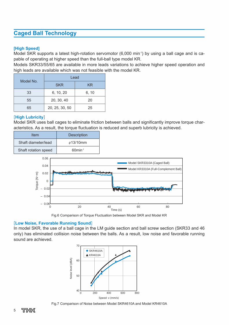
[High Speed] Model SKR supports a latest high-rotation servomotor (6,000 min -1 ) by using a ball cage and is ca-pable of operating at higher speed than the full-ball type model KR. Models SKR33/55/65 are available in more leads variations to achieve higher speed operation and high leads are available which was not feasible with the model KR.
Model No. Lead
SKR KR
33 6, 10, 20 6, 10
55 20, 30, 40 20
65 20, 25, 30, 50 25
[High Lubricity] Model SKR uses ball cages to eliminate friction between balls and signifi cantly improve torque char-acteristics. As a result, the torque fl uctuation is reduced and superb lubricity is achieved.
Item Description
Shaft diameter/lead 13/10mm
Shaft rotation speed 60min -1
Model SKR3310A (Caged Ball)
Model KR3310A (Full-Complement Ball)
To
rqu
e (
N•m
)
Time (s) 0 20 40 60 80
0.06
0.04
0.02
0
– 0.02
– 0.04
– 0.06
Fig.6 Comparison of Torque Fluctuation between Model SKR and Model KR
[Low Noise, Favorable Running Sound] In model SKR, the use of a ball cage in the LM guide section and ball screw section (SKR33 and 46 only) has eliminated collision noise between the balls. As a result, low noise and favorable running sound are achieved.
Speed: v (mm/s)
No
ise
le
ve
l (d
BA
)
SKR4610A
KR4610A
70
60
50
40 0 200 400 600 800
Fig.7 Comparison of Noise between Model SKR4610A and Model KR4610A

6
SKR [Long-term Maintenance-free Operation] With model SKR, the ball cage effect helps increase grease retention and achieve long-term mainte-nance-free operation.
[Long service life—3 times] With model SKR, both the LM Guide unit and the Ball Screw unit have larger basic dynamic load ratings than the full-ball type model KR, and therefore a longer service lives are achieved. The rated service life is calculated from the following equation.
LM guide unit L=(C/P) 3 ×50 L : Nominal life (km) C : Basic dynamic load rating (N) P : Applied load (N)
Ball screw unit L=(Ca/Fa) 3 ×10 6 L : Nominal life (rev) Ca : Basic dynamic load rating (N) Fa : Applied axial load (N)
As indicated in the equation above, the greater the basic dynamic load rating, the longer the service life of both the LM Guide unit and the Ball Screw unit.
Table2 Comparison of Basic Dynamic Load Rating between Model SKR and Model KR Unit: N
Basic dynamic load rat-ing
SKR20
KR20
SKR26
KR26
SKR33
KR33
SKR46
KR46
SKR55
KR55
SKR65
KR65
LM guide unit C
Long type block 6010 3590 13000 7240 17000 11600 39500 27400 55400 38100 74400 50900
Short type block — — — — 11300 4900 28400 14000 — — — —
Ball screw unit Ca 660 660 2350 2350 2700 1760 4240 3040 10900 3620 12000 5680
Note) On the SKR20/26, only the LM guide section features a ball cage.
[Seal] Model SKR is equipped with end seals and side seals for dust prevention as standard.
End seal
Side seal
Table3 shows the rolling resistance and seal resistance per inner block (guide section).
Table3 Maximum Resistance Value Unit: N
Model No. Rolling
resistancevalue
Sealresistance
value Total
SKR20 4.0 0.8 4.8 SKR26 4.5 1.2 5.7 SKR33 3.0 1.7 4.7 SKR46 6.0 2.1 8.1 SKR55 14.0 3.8 17.8 SKR65 20.0 4.1 24.1

7
Types and Features
Model SKR-A (with a Single Long Type Block) Basic model of SKR.
Model SKR-A
Model SKR-B (with Two Long Type Blocks) Equipped with two inner blocks of model SKR-A, this model achieves higher rigidity and higher load carrying capacity.
Model SKR-B
Model SKR-C (with a Single Short Type Block) This model has a shorter inner block and a lon-ger stroke than model SKR-A. *With model SKR3320, a short-block type is not available.
Model SKR-C
Model SKR-D (with Two Short Type Blocks) Equipped with two inner blocks of model SKR-C, this design allows a span between blocks that suits the equipment, thus to achieve high rigidity. *With model SKR3320, a short-block type is not available.
Model SKR-D

8
SKR
Load Ratings in All Directions and Static Permissible Moment
[Load Rating] Caged Ball LM Guide Actuator Model SKR con-sists of an LM Guide, a Ball Screw and a sup-port bearing.
Reverse radial loadRadial load
Lateral
load
Lateral
load
PLPR
PT PT
LM Guide Unit Model SKR is capable of receiving loads in four directions (radial, reverse radial and lateral direc-tions). Its basic load ratings are equal in all four directions (radial, reverse radial and lateral direc-tions), and their values are indicated in Table4 .
Ball Screw Unit Since the inner block is incorporated with a ball screw nut, model SKR is capable of receiving an axial load. The basic load rating value is indicated in Table4 .
Bearing Unit (Fixed Side) Since housing A contains an angular bearing, model SKR is capable of receiving an axial load. The basic load rating value is indicated in Table4 .
[Equivalent Load (LM Guide Unit)] The equivalent load when the LM Guide unit of model SKR simultaneously receives loads in all directions is obtained from the following equation.
PE = PR (PL) + PT
P E : Equivalent load (N) : Radial direction : Reverse radial direction : Lateral directions P R : Radial load (N) P L : Reverse radial load (N) P T : Lateral load (N)

9
Table4 Load Rating of Model SKR
Model No. SKR20 SKR26 SKR33 * SKR2001 SKR2006 SKR2602 SKR2606 SKR3306 SKR3310 SKR3320
LM g
uide
uni
t
Basic dynamicload rating
C (N)
Long type block 6010 13000 17000
Short type block — — 11300 —
Basic staticload rating
C 0 (N)
Long type block 8030 16500 20400
Short type block — — 11500 —
Radialclearance
(mm)
Normal grade, high accuracy grade ‒0.004 to 0 ‒0.006 to 0 –0.004 to 0
Precision grade –0.006 to –0.004
–0.007 to –0.006 –0.012 to –0.004
Bal
l scr
ew u
nit
Basic dynamic load rating
Ca (N)
Normal grade, high accuracy grade 660 860 2350 1950
4400 2700 2620 Precision grade 660 1060 2350 2390
Basic static load rating
C 0 a (N)
Normal grade, high accuracy grade 1170 1450 4020 3510
6290 3780 3770 Precision grade 1170 1600 4020 3900
Screw shaft diameter (mm) 6 8 13
Ball Screw lead (mm) 1 6 2 6 6 10 20
Thread minor diameter (mm) 5.3 5.0 6.6 6.7 10.8
Ball center-to-center diameter (mm) 6.15 6.3 8.3 8.4 13.5
Bea
ring
unit
(Fix
ed s
ide)
Axial direction
Basic dynamicload rating
Ca (N) 1150 2000 6250
Static permissibleload
P 0 a (N) 735 1230 2700
* For use in a special environment or where an axial load (25% or more of the basic dynamic load rating Ca) is applied, a special type is also available. Contact THK for details.
Note1) The load ratings in the LM Guide unit each indicate the load rating per inner block. Note2) With model SKR3320, a short-block type is not available.

10
SKR
SKR46 * SKR55 SKR65 SKR4610 SKR4620 SKR5520 SKR5530 SKR5540 SKR6520 SKR6525 SKR6530 SKR6550
39500 55400 74400
28400 — —
45900 62500 81600
28700 — —
–0.006 to 0 ‒0.007 to 0 ‒0.008 to 0
‒0.016 to ‒0.006 ‒0.019 to ‒0.007 ‒0.022 to ‒0.008
4350 4240 10900 7000 6800 12100 12000 8200 7600
6990 7040 17600 11500 9900 21600 22000 14500 12600
15 20 25
10 20 20 30 40 20 25 30 50
12.5 17.1 22.1
15.75 20.75 25.75
6700 7600 13700
3330 3990 5830
11
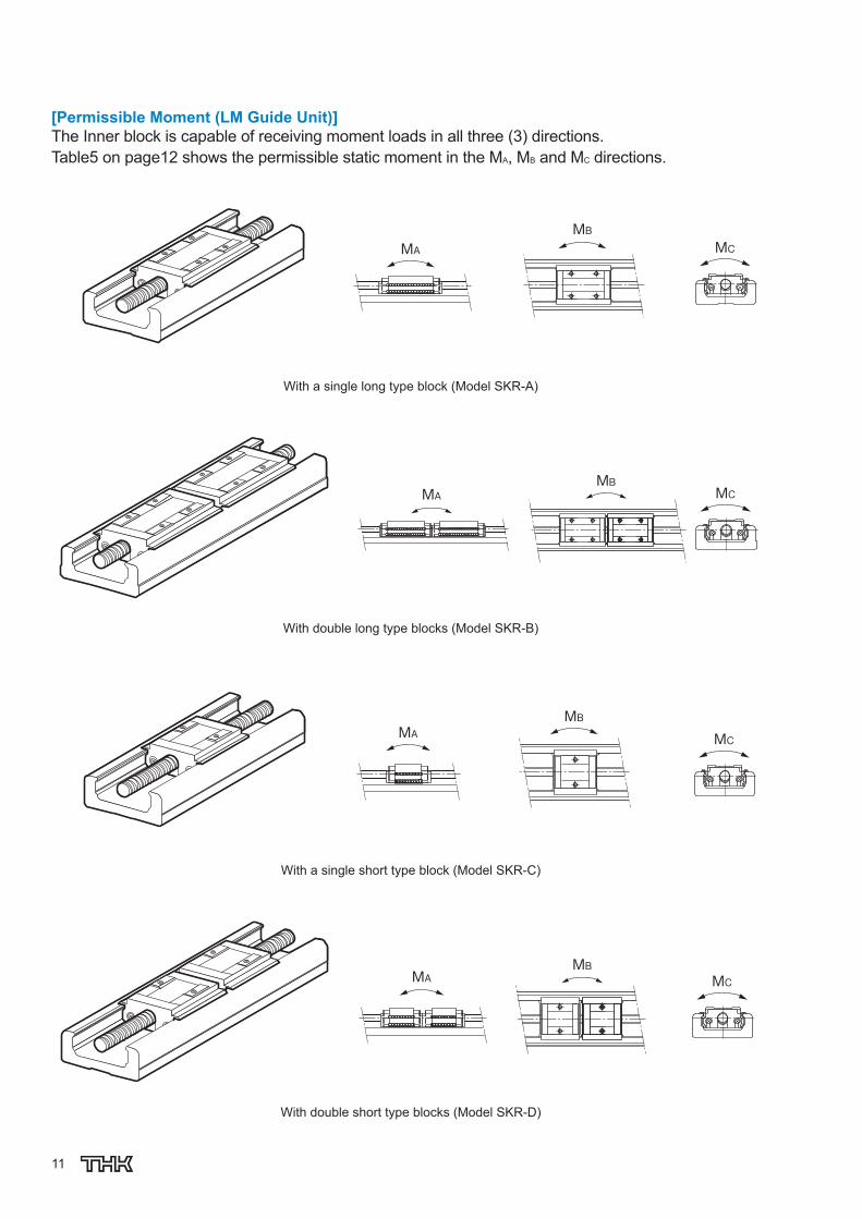
[Permissible Moment (LM Guide Unit)] The Inner block is capable of receiving moment loads in all three (3) directions. Table5 on page12 shows the permissible static moment in the M A , M B and M C directions.
MAMB
MC
With a single long type block (Model SKR-A)
MCMAMB
With double long type blocks (Model SKR-B)
MCMAMB
With a single short type block (Model SKR-C)
MAMB
MC
With double short type blocks (Model SKR-D)

12
SKRTable5 Static Permissible Moments of Model SKR Unit: N·m
Model No. Static permissible moment
M A M B M C
SKR20-A 38 38 98
SKR20-B 207 207 197
SKR26-A 117 117 265
SKR26-B 589 589 530
SKR33-A 173 173 424
SKR33-B 990 990 848
SKR33-C 58 58 240
SKR33-D 390 390 480
SKR46-A 579 579 1390
SKR46-B 3240 3240 2780
SKR46-C 236 236 870
SKR46-D 1460 1460 1740
SKR55-A 923 923 2276
SKR55-B 5125 5125 4552
SKR65-A 1366 1366 3868
SKR65-B 7702 7702 7736
Note1) Symbols A, B, C or D in the end of each model number indicates the inner block size and the number of inner blocks used. A: With a single long type block B: With double long type blocks C: With a single short type block D: With double short type blocks
Note2) The values for models SKR-B/D indicate the values when double inner blocks are used in close contact with each other.
Note3) Static permissible moment is the maximum moment that can be permitted while the product is stationary.
13
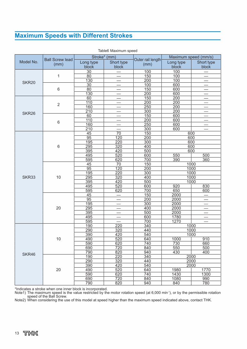
Maximum Speeds with Different Strokes
Table6 Maximum speed
Model No. Ball Screw lead(mm)
Stroke * (mm) Outer rail length (mm)
Maximum speed (mm/s) Long type
block Short type
block Long type
block Short type
block
SKR20 1
30 — 100 100 — 80 — 150 100 —
130 — 200 100 —
6 30 — 100 600 — 80 — 150 600 —
130 — 200 600 —
SKR26
2 60 — 150 200 — 110 — 200 200 — 160 — 250 200 — 210 — 300 200 —
6 60 — 150 600 — 110 — 200 600 — 160 — 250 600 — 210 — 300 600 —
SKR33
6
45 70 150 600 95 120 200 600
195 220 300 600 295 320 400 600 395 420 500 600 495 520 600 550 500 595 620 700 390 360
10
45 70 150 1000 95 120 200 1000
195 220 300 1000 295 320 400 1000 395 420 500 1000 495 520 600 920 830 595 620 700 650 600
20
45 — 150 2000 — 95 — 200 2000 — 195 — 300 2000 — 295 — 400 2000 — 395 — 500 2000 — 495 — 600 1780 — 595 — 700 1270 —
SKR46
10
190 220 340 1000 290 320 440 1000 390 420 540 1000 490 520 640 1000 910 590 620 740 730 660 690 720 840 550 500 790 820 940 430 400
20
190 220 340 2000 290 320 440 2000 390 420 540 2000 490 520 640 1980 1770 590 620 740 1430 1300 690 720 840 1080 990 790 820 940 840 780
* Indicates a stroke when one inner block is incorporated. Note1) The maximum speed is the value restricted by the motor rotation speed (at 6,000 min -1 ), or by the permissible rotation
speed of the Ball Screw. Note2) When considering the use of this model at speed higher than the maximum speed indicated above, contact THK.
14
SKR
Model No. Ball Screw lead (mm)
Stroke * (mm) Outer rail length (mm)
Maximum speed (mm/s) Long type
block Short type
block Long type
block Short type
block
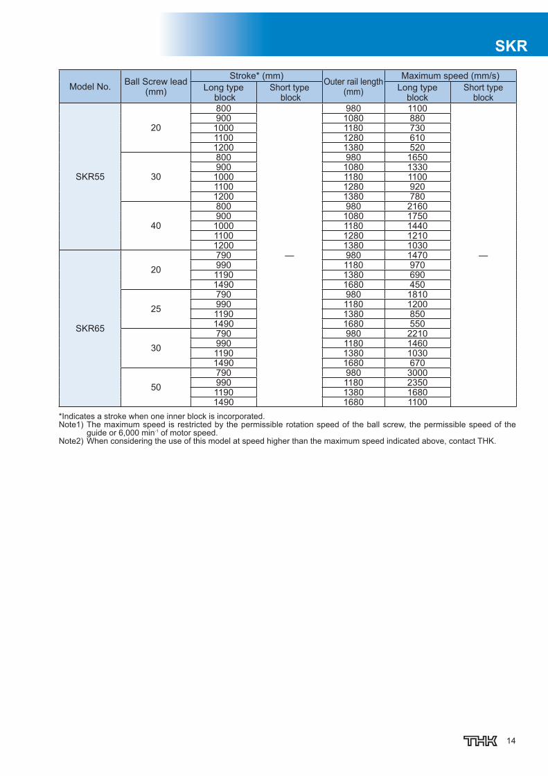
SKR55
20
800
—
980 1100
—
900 1080 880 1000 1180 730 1100 1280 610 1200 1380 520
30
800 980 1650 900 1080 1330 1000 1180 1100 1100 1280 920 1200 1380 780
40
800 980 2160 900 1080 1750 1000 1180 1440 1100 1280 1210 1200 1380 1030
SKR65
20 790 980 1470 990 1180 970 1190 1380 690 1490 1680 450
25 790 980 1810 990 1180 1200 1190 1380 850 1490 1680 550
30 790 980 2210 990 1180 1460 1190 1380 1030 1490 1680 670
50 790 980 3000 990 1180 2350 1190 1380 1680 1490 1680 1100
* Indicates a stroke when one inner block is incorporated. Note1) The maximum speed is restricted by the permissible rotation speed of the ball screw, the permissible speed of the
guide or 6,000 min -1 of motor speed. Note2) When considering the use of this model at speed higher than the maximum speed indicated above, contact THK.

15
Lubrication
Table7 shows standard greases used in model SKR and grease nipple types.
Table7 Types of standard grease and grease nipples used
Model No. Standard grease Grease nipple used
SKR20 THK AFA Grease PB107
SKR26 THK AFA Grease PB107
SKR33 THK AFB-LF Grease PB107
SKR46 THK AFB-LF Grease A-M6F
SKR55 THK AFB-LF Grease A-M6F
SKR65 THK AFB-LF Grease A-M6F
Static Safety Factor
Caged Ball LM Guide Actuator Model SKR consists of an LM Guide, a Ball Screw and a support bearing. The static safety factor and the service life of each component can be obtained from the basic load rating indicated in “Rated load of model SKR” (see Table4 on page10 ).
[Calculating the Static Safety Factor] LM Guide Unit
To calculate a load applied to the LM Guide of model SKR, the average load required for calculating the service life and the maximum load needed for calculating the static safety factor must be ob-tained fi rst. In particular, if the system starts and stops frequently, or if a large moment caused by an overhung load is applied to the system, it may receive an unexpectedly large load. When selecting a model number, make sure that the desired model is capable of receiving the re-quired maximum load (whether stationary or in motion).
fs = Pmax
C0
f S : Static safety factor C 0 : Basic static load rating (N) P max : Maximum applied load (N)
* The basic static load rating is a static load with a constant direction and magnitude whereby the sum of the permanent defor-mation of the rolling element and that of the raceway on the contact area under the maximum stress is 0.0001 times the roll-ing element diameter.

16
SKR
Ball Screw Unit/Bearing Unit(Fixed Side) If an unexpected external force is applied in the axial direction as a result of an inertia caused by an impact or start and stop while model SKR is stationary or operating, it is necessary to take into ac-count the static safety factor.
fs = Fmax
C0a
f S : Static safety factor C 0a : Basic static load rating (N) F max : Maximum applied load (N)
[Standard Values for the Static Safety Factor (f S )]
Machine type Load conditions Minimum Static Safety Factor (f S )
General industrial machinery Without vibration or impact 1.0 to 3.5
With vibration or impact 2.0 to 5.0
* The standard value of the static safety factor may vary depending on the load conditions as well as environment, lubrication status, mounting accuracy, and/or rigidity.
Service Life
[LM Guide Unit] Nominal Life
The nominal life (L) means the total travel distance that 90% of a group of units of the same LM Guide model can achieve without fl aking (scale-like pieces on the metal surface) after individually running under the same conditions. The nominal life of the LM Guide is obtained using the following equation.
fW•PCL =
3
50 fC•C
L : Nominal life (km) C : Basic dynamic load rating (N) P C : Calculated applied load (N)
f W : Load factor (see Table8 on page17 ) f C : Contact factor (see Table9 on page18 )
● If a moment is applied, calculate the equivalent load by multiplying the applied moment by the equivalent factor indicated in Table10 on page 18 .
Pm = K•M P m : Equivalent load (per inner block) (N) K : Equivalent moment factor M : Applied moment (N·mm) (If planning to use the product with a wide inner block span, contact THK.) If moment Mc is applied to model SKR-B/D
Pm = KC•MC
2● If a radial load (P) and a moment are simultaneously applied to model SKR
PE = Pm + P
P E : Overall equivalent radial load (N) Perform a nominal life calculation using the above data.
17
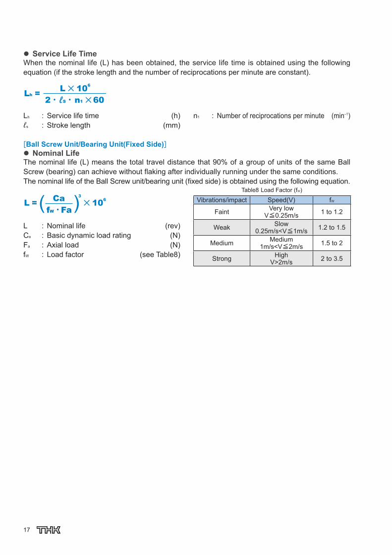
Service Life Time When the nominal life (L) has been obtained, the service life time is obtained using the following equation (if the stroke length and the number of reciprocations per minute are constant).
2 • ℓS • n1 60
Lh = L 106
L h : Service life time (h) ℓ s : Stroke length (mm)
n 1 : Number of reciprocations per minute (min –1 )
[Ball Screw Unit/Bearing Unit(Fixed Side)]
Nominal Life The nominal life (L) means the total travel distance that 90% of a group of units of the same Ball Screw (bearing) can achieve without fl aking after individually running under the same conditions. The nominal life of the Ball Screw unit/bearing unit (fi xed side) is obtained using the following equation.
Ca L = 3
106
fW •Fa
L : Nominal life (rev) C a : Basic dynamic load rating (N) F a : Axial load (N) f W : Load factor (see Table8 )
Table8 Load Factor (f W )
Vibrations/impact Speed(V) f W
Faint Very low V≦0.25m/s 1 to 1.2
Weak Slow 0.25m/s<V≦1m/s 1.2 to 1.5
Medium Medium 1m/s<V≦2m/s 1.5 to 2
Strong High V>2m/s 2 to 3.5

18
SKR
Service Life Time When the nominal life (L) has been obtained, the service life time is obtained using the following equation (if the stroke length and the number of reciprocations per minute are constant).
L• ℓLh =
2 • ℓS • n1 60 L h : Service life time (h) ℓ s : Stroke length (mm)
n 1 : Number of reciprocations per minute (min –1 ) ℓ : Ball Screw lead (mm)
f C : Contact Factor If two inner blocks are used in close contact with each other with model SKR-B/D, multiply the basic load rating by the corresponding con-tact factor indicated in Table9 .
Table9 Contact Factor (f C )
Block type Contact factor f C Model SKR-B Model SKR-D 0.81
f W : Load Factor In general, machines in reciprocal motion are likely to cause vibration and impact during operation, and it is particularly diffi cult to accurately determine each of vibration generated during high-speed operation, impact applied during repeated starting and stopping in normal use, etc. Therefore, where the effect of speed vibration is estimated to be signifi cant, divide the basic load rating (C) by an em-pirically obtained load factor.
K: Moment Equivalent Factor (LM Guide Unit) When model SKR travels under a moment, the distribution of load applied to the LM Guide is locally large. In such cases, calculate the load by multiplying the moment value by the corre-sponding moment equivalent factor indicated in Table10 . Symbols K A , K B and K C indicate the moment equivalent loads in the M A , M B and M C direc-tions, respectively.
Table10 Equivalent moment factor(K)
Model No. K A K B K C SKR20-A 2.34×10 –1 2.34×10 –1 8.07×10 –2 SKR20-B 4.38×10 –2 4.38×10 –2 8.07×10 –2 SKR26-A 1.59×10 –1 1.59×10 –1 6.17×10 –2 SKR26-B 3.18×10 –2 3.18×10 –2 6.17×10 –2 SKR33-A 1.42×10 –1 1.42×10 –1 5.05×10 –2 SKR33-B 2.47×10 –2 2.47×10 –2 5.05×10 –2 SKR33-C 2.39×10 –1 2.39×10 –1 5.05×10 –2 SKR33-D 3.54×10 –2 3.54×10 –2 5.05×10 –2 SKR46-A 9.51×10 –2 9.51×10 –2 3.46×10 –2 SKR46-B 1.70×10 –2 1.70×10 –2 3.46×10 –2 SKR46-C 1.46×10 –1 1.46×10 –1 3.46×10 –2 SKR46-D 2.36×10 –2 2.36×10 –2 3.46×10 –2 SKR55-A 8.12×10 ‒2 8.12×10 ‒2 2.88×10 ‒2 SKR55-B 1.46×10 ‒2 1.46×10 ‒2 2.88×10 ‒2 SKR65-A 7.16×10 ‒2 7.16×10 ‒2 2.21×10 ‒2 SKR65-B 1.27×10 ‒2 1.27×10 ‒2 2.21×10 ‒2
K A : Moment equivalent factor in the M A direction.K B : Moment equivalent factor in the M B direction.K C : Moment equivalent factor in the M C direction. Note) The values for models SKR-B/D indicate the values
when double inner blocks are used in close contact with each other.

19
Accuracy Standards
The accuracy standard of model SKR is defi ned in positioning repeatability, positioning accuracy, running parallelism (vertical direction) and backlash.
[Positioning Repeatability] Command the position to a given arbitrary point. Measure the position and repeat seven times from the same direction. Record the difference between the largest and smallest values. Con-duct the same test at three points: the middle of the stroke, and at both the approximate maxi-mum and minimum positions of travel. Express the maximum difference value of the three mea-surements divided by 2 with a “±” sign.
t1
t2
t3
Fig.8 Positioning Repeatability
[Positioning Accuracy] Using the maximum stroke as the reference length, express the maximum error between the actual distance traveled from the reference point and the command value in an absolute value as positioning accuracy.
�A=|Actual distance traveled - travel distance
of the command value|
�A Command value
�A Travel distance
(Error)
Ref
eren
ce p
oint
△A
0
(+)
(ー) Fig.9 Positioning Accuracy
[Running of Parallelism (Vertical direction)] Place a straightedge on the surface table where model SKR is mounted, measure almost throughout the travel distance of the inner block using a test indicator. Use the maximum differ-ence among the readings within the travel dis-tance as the running parallelism measurement.
Straightedge
Fig.10 Running of Parallelism [Backlash] Feed and slightly move the inner block and read the measurement on the test indicator as the reference value. Subsequently, apply a load to the inner block from the same direction (table feed direction), and then release the inner block from the load. Use the difference between the reference value and the return as the backlash measurement. Perform this measurement in the center and near both ends, and use the maximum value as the measurement value.
Backlash
Feed screw feed
Return
Load Load displacement
(including elastic displacement)
Fig.11 Backlash

20
SKR The accuracies of model SKR are classifi ed into normal grade (no symbol), high accuracy grade (H) and precision grade (P). Tables below show standards for all the accuracies.
Table11 Normal Grade (No Symbol) Unit: mm
Model No. Stroke * Outer rail length
Positioning Repeatability
PositioningAccuracy
Running Parallelism (Vertical Direction) Backlash Starting torque
(N·cm)
SKR20 30 100
0.01 No standard defi ned
No standard defi ned 0.02 0.5 80 150
130 200
SKR26
60 150
0.01 No standard defi ned
No standard defi ned 0.02 1.5 110 200
160 250 210 300
SKR33
45 150
0.01 No standard defi ned
No standard defi ned 0.02 7
95 200 195 300 295 400 395 500 495 600 595 700
SKR46
190 340
0.01 No standard defi ned
No standard defi ned 0.02 10
290 440 390 540 490 640 590 740 690 840 790 940
SKR55
800 980
0.01 No standard defi ned
No standard defi ned 0.05 12
900 1080 1000 1180 1100 1280 1200 1380
SKR65
790 980 0.01 No standard
defi ned No standard
defi ned 0.05 12 990 1180 1190 1380 1490 1680 0.012 15
* Indicates stroke length when one long-type inner block is incorporated. Note1) The evaluation method for accuracy standards complies with THK standards. Note2) The starting torque represents the value when the following grease is used.
Models SKR20 and SKR26 : THK AFA Grease Models SKR33, SKR46, SKR55 and SKR65 : THK AFB-LF Grease
Note3) If highly viscous grease such as vacuum grease and clean room grease is used, the actual starting torque may ex-ceed the corresponding value in the table. Use much care in selecting a motor.
Note4) Contact THK for accuracy information of units longer than the standard length.

21
Table12 High Accuracy Grade (H) Unit: mm
Model No. Stroke * Outer rail length
Positioning Repeatability
PositioningAccuracy
Running of Parallelism (Vertical direction) Backlash Starting torque
(N·cm)
SKR20 30 100
0.005 0.06 0.025 0.01 0.5 80 150 130 200
SKR26
60 150
0.005 0.06 0.025 0.01 1.5 110 200 160 250 210 300
SKR33
45 150
0.005
0.06 0.025
0.02 7
95 200 195 300 295 400 395 500 0.10 0.035 495 600 595 700 0.12 0.04
SKR46
190 340
0.005
0.10 0.035
0.02 10
290 440 390 540 490 640 590 740 0.12 0.04 690 840 790 940 0.15 0.05
SKR55
800 980
0.005
0.18
0.05 0.05 12 900 1080 1000 1180
0.25 1100 1280 1200 1380
SKR65
790 980
0.008
0.18 0.05 0.05 12 990 1180 0.2 1190 1380
1490 1680 0.28 0.055 15 * Indicates stroke length when one long-type inner block is incorporated.

22
SKRTable13 Precision Grade (P) Unit: mm
Model No. Stroke * Outer rail length
Positioning Repeatability
PositioningAccuracy
Running of Parallelism (Vertical direction) Backlash Starting torque
(N·cm)
SKR20 30 100
0.003 0.02 0.01 0.003 1.2 80 150 130 200
SKR26
60 150
0.003 0.02 0.01 0.003 4 110 200 160 250 210 300
SKR33
45 150
0.003
0.02 0.01
0.003 15
95 200 195 300 295 400 395 500 0.025 0.015 495 600 595 700 0.03 0.02
SKR46
190 340
0.003 0.025 0.015 0.003 15 290 440
390 540 490 640 17 590 740 0.03 0.02
SKR55 800 980
0.005 0.035 0.025 0.003 17 900 1080 1000 1180 0.04 0.03 20
SKR65 790 980
0.005 0.035 0.025 0.005 20 990 1180 1190 1380 0.04 0.03 22
* Indicates stroke length when one long-type inner block is incorporated. Note1) The evaluation method for accuracy standards complies with THK standards. Note2) The starting torque represents the value when the following grease is used.
Models SKR20 and SKR26 : THK AFA Grease Models SKR33, SKR46, SKR55 and SKR65 : THK AFB-LF Grease
Note3) If highly viscous grease such as vacuum grease and clean room grease is used, the actual starting torque may ex-ceed the corresponding value in the table. Use much care in selecting a motor.
Note4) Contact THK for accuracy information of units longer than the standard length.

23
Model Number Coding
Mo d e l No . In n e r b l o c k t y p e St r o k e Ac c u r a c yBa l l Sc r e w Le a d
No symbol: normal grade
H : High accuracy grade
P : Precision Grade
The available ball screw leads differ depending on the model.
SKR20 : "01", "06"
SKR26 : "02", "06"
SKR33 : "06", "10", "20" (20 mm is available for inner block type A and B only)
SKR46 : "10", "20"
SKR55 : "20", "30", "40"
SKR65 : "20", "25", "30", "50"
SKR33 A - -0195 P10① ③ ④ ⑤②
SKR20 A 01 : 1mm
SKR26 B 02 : 2mm
SKR33 C 06 : 6mm
SKR46 D 10 : 10mm
20 : 20mm
25 : 25mm
30 : 30mm
40 : 40mm
50 : 50mm
If "2" (with Bellows) was selected for the cover ⑦, specify
a stroke incorporating the bellows(→page82).
~ 0025 : 25mm
0050 : 50mm
1490 : 1490mm
SKR55
SKR65
24
SKR
((
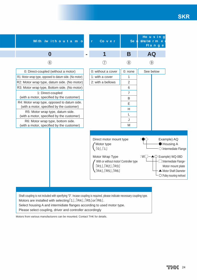
Co v e r Se n s o rHo u s i n g A/
In t e r m e d i a t e Fl a n g e
Wi th /w i t h o u t a m o t o r
0: without a cover 0: none
1: with a cover
2: with a bellows
Direct motor mount type : Motor type
「0」,「1」
Motor Wrap Type : With or without motor/ Controller type
「R1」,「R2」,「R3」 「R4」,「R5」,「R6」
●◇ Example) AQ
●:Housing A
◇:Intermediate Flange
W□-▲〇 Example) WQ-08D
□:Intermediate Flange・ Motor mount plate
▲:Motor Shaft Diameter
〇:Pulley mounting methoed
Shaft coupling is not included with sperifying "0". Incase coupling is required, please indicate necessary coupling type.
Motors are installed with selecting「1」,「R4」,「R5」or「R6」.Select housing A and intermidiate flanges according to used motor type.
Please select coupling, driver and controller accordingly
0: Direct-coupled (without a motor)
R1: Motor wrap type, opposed to datum side. (No motor)
R2: Motor wrap type, datum side. (No motor)
R3: Motor wrap type, Bottom side. (No motor)
1: Direct-coupled
(with a motor, specified by the customer)
R4: Motor wrap type, opposed to datum side.
(with a motor, specified by the customer)
R5: Motor wrap type, datum side.
(with a motor, specified by the customer)
R6: Motor wrap type, bottom side.
(with a motor, specified by the customer)
See below
Motors from various manufacturers can be mounted. Contact THK for details.
1 B AQ0⑦ ⑧ ⑨⑥
1
2
6
7
B
E
H
L
J
M
-

25 To download a desired data, search for the corresponding model number in the Technical site. https://tech.thk.com
Model SKR20 (without a Cover) Model SKR20□□A (with a Single Long Type Block)Model SKR20□□B (with Two Long Type Blocks)For model number coding, see page23.
φ20
*1 Distance between the mechanical stopper and the stroke starting position.
*2 Indicates the inner block length when calculating the available stroke range.
The length in model SKR-B (with two long-type inner blocks) is 90.6 mm.
B-B cross sectionA arrow view
2×2-M2.6 depth 4
(Same position on the opposite side)
(Sensor rail mounting hole)
4-M3 depth 6
4-3.4 through hole
(Dimension with twoblocks in close contact)
Stroke
Type A (5.4)
Type B (4.4)
4-M3 depth 32-M2.6 depth 4
2×n-3.4 through hole φ 6.5 counter bore depth 3
2-M1.6 depth 2.4
(Sensor target mounting hole)
Outer rail length
Type A (11.4)
Type B (10.4)
G
60
12 25 12 46MIN
10
(n-1)×60
0.9
10
B
B
3.5
40
1118
20
15.8
2 13
23
(G) 2.5
A
39.6
9.5
30
30°
0.5
29.5
33.6
3.3
30°
12.5
PCD29
3
φ23H
7
φ4h7
20
46
33.2
(14)(5.5)*1
18
1L
8
14
49 10
(44.6)*2(44.6)46
Stroke (mm)(stroke between mechanical stoppers) Overall length
L1(mm)Outer rail length
(mm)G
(mm) n Overall main unit mass (kg)
Type A Type B* Type A Type B30(40.9) — 159 100 20 2 0.45 —80(90.9) 35(44.9) 209 150 15 3 0.58 0.66
130(140.9) 85(94.9) 259 200 40 3 0.72 0.8*Indicates a value when two inner blocks are in close contact with each other.

26
SKR
Options⇒page60
Model SKR20 (with a Cover)Model SKR20□□A (with a Single Long Type Block)Model SKR20□□B (with Two Long Type Blocks)For model number coding, see page23.
(19.7)(5.5)* 20
33.233.2
45
B′6
8.5
13
32
17
.5
40
(1)
52
18
37
A
B′
39.6
9.5
30
30°
PCD29
0.5
29.5
33.6
3.3
30°
Stroke
Type A (17.1)
Type B (16.1)
Type A (5.4)
Type B (4.4)
4-M4 through
(Sensor target mounting hole)2×2-M2 depth 4 (Same position on the opposite side)
B′-B′ cross sectionA arrow view
4-3.4 through hole
4-M3 depth 6
* Distance between the mechanical stopper and the stroke starting position.
12.5
Stroke (mm)(stroke between mechanical stoppers) Overall length
L1(mm)Outer rail length
(mm)Overall main unit mass (kg)
Type A Type B* Type A Type B30(40.9) — 159 100 0.5 —80(90.9) 35(44.9) 209 150 0.64 0.76
130(140.9) 85(94.9) 259 200 0.79 0.91*Indicates a value when two inner blocks are in close contact with each other.

27 To download a desired data, search for the corresponding model number in the Technical site. https://tech.thk.com
Model SKR20 Motor wrap, (without a Cover)Model SKR20□□A (with a Single Long Type Block)Model SKR20□□B (with Two Long Type Blocks)For model number coding, see page23.
60
(Center distance)
(61)
(16)
Detail, inner block
Outer rail length
Type A(5.4)*1
Type B(4.4)*1
Type A(11.4)Type B(10.4)
B-B cross section
46MIN
(Dimension with twoblocks in close contact)
2×n-3.4 through hole φ6.5 counter bore depth 3
2×2-M2.6 depth 4
(Same position on the opposite side)(Sensor rail mounting hole)
(C
ente
r dis
tance)
4-M3 depth 3 2-M1.6 depth 2.4
(Sensor target mounting hole)
*1 Distance between the mechanical stopper and the stroke starting position.
*2 Indicates the inner block length when calculating the available stroke range.
The length in model SKR-B (with two long-type inner blocks) is 90.6 mm.
Motor wrap type, Bottom side
(4)
(21.8)
(100.8)
(43.6)(8.8)
(1)
L1
10
46 46
(5.5)*1
Stroke(14) (44.6)*2 (44.6)*2
12(27.8)
23
1118
40
220
15
.8
13
2-(R2)
B
B0.9
10
10
3.5 G (n-1)×60 (G) 2.5
(1)
(100.8)
(43.6)
(21.8)
(1)
(71.8) (61)
18
20
33.2
6.6
Stroke (mm)(stroke between mechanical stoppers) Overall length
L1(mm)Outer rail length
(mm)G
(mm) n Overall main unit mass(kg)
Type A Type B* Type A Type B30(40.9) ― 149.8 100 20 2 0.71 0.7980(90.9) 35(44.9) 199.8 150 15 3 0.84 0.92
130(140.9) 85(94.9) 249.8 200 40 3 0.98 1.06*Indicates a value when two inner blocks are in close contact with each other.

28
SKR
Options⇒page60
Model SKR20 Motor wrap (with a Cover)Model SKR20□□A (with a Single Long Type Block)Model SKR20□□B (with Two Long Type Blocks)For model number coding, see page23.
52
StrokeType A(17.1)Type B(16.1)Type A(5.4)*1
Type B(4.4)*1
2×2-M2 depth 4
(Same position on the opposite side)(Sensor target mounting hole)
(Dimension with two blocks in close contact)
B′-B′ cross section
*1 Distance between the mechanical stopper and the stroke starting position.
4-M4 through
Detail, Top tableMotor wrap type, Bottom side
33.2 33.2(19.7)(5.5)*1
B′
B′6
46MIN8.5
17
.5
32
37
18 11
40
132
2-(R2)
(1)
(103.8)
6.620
(3.5)
45
3.5
(2.8)
Stroke (mm)(stroke between mechanical stoppers) Overall length
L1(mm)Outer rail length
(mm)Overall main unit mass(kg)
Type A Type B* Type A Type B30(40.9) ― 149.8 100 0.76 0.8880(90.9) 35(44.9) 199.8 150 0.9 1.02
130(140.9) 85(94.9) 249.8 200 1.05 1.17*Indicates a value when two inner blocks are in close contact with each other.

29 To download a desired data, search for the corresponding model number in the Technical site. https://tech.thk.com
Model SKR26 (without a Cover) Model SKR26□□A (with a Single Long Type Block)Model SKR26□□B (with Two Long Type Blocks)For model number coding, see page23.
*1 Distance between the mechanical stopper and the stroke starting position.
*2 Indicates the inner block length when calculating the available stroke range.
The length in model SKR-B (with two long-type inner blocks) is 126.8 mm.
(Same position on the opposite side)
(Sensor rail mounting hole)
4-M3 depth 6
2×2-M2.6 depth 4
(Dimension with two blocks in close contact)
4-3.5 through hole
A arrow view B-B cross section
Stroke
Type A (3.7)
Type B (4.5)
Type A (9.7)
Type B (10.5)
2-M2 depth 3
(Sensor target mounting hole) 4-M4 depth 42-M3 depth 5
Outer rail length
2×n-4.5 through hole φ 8 counter bore depth 4
φ24H
7
G
80
3.5
12 34 14
B
B
12
15
(G)(n-1)×80 2.5
64.2 MIN
26
31
21
49.4
11
PC
D33
38
43
12.525
50
2 16
0.5
38.5
6.5
45°
45°
A
0.9
L1
47.4
(62.6)*2
30
(4.7)*1
(17.7)
60
16.5
φ5h7
25
10
10
64.2 64.2
(62.6)
Stroke (mm)(stroke between mechanical stoppers) Overall length
L1(mm)Outer rail length
(mm)G
(mm) n Overall main unit mass (kg)
Type A Type B* Type A Type B60(68.4) — 220 150 35 2 0.99 —
110(118.4) 45(54.2) 270 200 20 3 1.2 1.38160(168.4) 95(104.2) 320 250 45 3 1.41 1.59210(218.4) 145(154.2) 370 300 30 4 1.62 1.8
*Indicates a value when two inner blocks are in close contact with each other.

30
SKR
Options⇒page60
Model SKR26 (with a Cover)Model SKR26□□A (with a Single Long Type Block)Model SKR26□□B (with Two Long Type Blocks)For model number coding, see page23.
* Distance between the mechanical stopper and the stroke starting position.
(Same position on the opposite side)(Sensor target mounting hole)
2×2-M2 depth 4
4-M3 depth 6
4-3.5 through hole
B′-B′ cross sectionA arrow view
Type A (17.3)Type B (18.1)
Type A (3.7)
Type B (4.5)
4-M4 through
Stroke
8.5
49.4
11
PC
D33
38
43
0.5
38.5
6.5
45°
45° 1
6
50
23
40
(0.3
)
6247
24
A
B′
B′
47.447.4
30
55
(25.3)(4.7)*
Stroke (mm)(stroke between mechanical stoppers) Overall length
L1(mm)Outer rail length
(mm)Overall main unit mass (kg)
Type A Type B* Type A Type B60(68.4) — 220 150 1.1 —
110(118.4) 45(54.2) 270 200 1.32 1.57160(168.4) 95(104.2) 320 250 1.54 1.79210(218.4) 145(154.2) 370 300 1.76 2.01
*Indicates a value when two inner blocks are in close contact with each other.

31 To download a desired data, search for the corresponding model number in the Technical site. https://tech.thk.com
Model SKR26 Motor wrap, (without a Cover)Model SKR26□□A (with a Single Long Type Block)Model SKR26□□B (with Two Long Type Blocks)For model number coding, see page23.
47.4
30 8.7
23.74-M4 depth 4
25
2-M2 depth 3
Detail, inner block
Outer rail length
StrokeType A(9.7)Type B(10.5)Type A(3.7)*1
Type B(4.5)*1
B-B cross section
(Dimension with twoblocks in close contact)
2×2-M2.6 depth 4
(Same position on the opposite side)(Sensor rail mounting hole)
2×n-4.5 through hole φ8 counter bore depth 4
(C
ente
r dis
tance)
Motor wrap type, Bottom side
(1)
(107.8)
(9)
(21.8)
(43.6)(5.8)
L1
10
(17.7) (62.6)*2
(4.7)*1
(62.6)*2
64.264.2
(27.8)14
31
26
21
2
25 12.5
50
2-(R3)
16
B
B
64.2MIN15
0.9
(Center distance)
(68)
(16)
3.5 G (n-1)×80 (G) 2.512
80
*1 Distance between the mechanical stopper and the stroke starting position.
*2 Indicates the inner block length when calculating the available stroke range.
The length in model SKR-B (with two long-type inner blocks) is 126.8 mm.
(68)
(6.5)
(1)
(107.8)
(75.8)
(21.8)(43.6)
Stroke (mm)(stroke between mechanical stoppers) Overall length
L1(mm)Outer rail length
(mm)G
(mm) n Overall main unit mass(kg)
Type A Type B* Type A Type B60(68.4) ― 201.8 150 35 2 1.21 1.39
110(118.4) 45(54.2) 251.8 200 20 3 1.42 1.6160(168.4) 95(104.2) 301.8 250 45 3 1.63 1.81210(218.4) 145(154.2) 351.8 300 30 4 1.84 2.02
*Indicates a value when two inner blocks are in close contact with each other.

32
SKR
Options⇒page60
Model SKR26 Motor wrap (with a Cover)Model SKR26□□A (with a Single Long Type Block)Model SKR26□□B (with Two Long Type Blocks)For model number coding, see page23.
2-(R3)
Type A(17.3)Type B(18.1)Type A(3.7)*1
Type B(4.5)*1
2×2-M2 depth 4
(Same position on the opposite side)(Sensor target mounting hole)
(Dimension with twoblocks in close contact)
B′-B′ cross section
4-M4 through
Detail, Top tableMotor wrap type, Bottom side
(2.2)
(4.7)*1
(25.3) 47.4 Stroke47.4
B′
B′
64.2MIN
8.5
12
47
40
23
2 16
25 12.5
50
62
*1 Distance between the mechanical stopper and the stroke starting position.
30 8.7
3.5
55
(3
.5)
(11
5.8)
Stroke (mm)(stroke between mechanical stoppers) Overall length
L1(mm)Outer rail length
(mm)Overall main unit mass(kg)
Type A Type B* Type A Type B60(68.4) ― 201.8 150 1.32 1.57
110(118.4) 45(54.2) 251.8 200 1.54 1.79160(168.4) 95(104.2) 301.8 250 1.76 2.01210(218.4) 145(154.2) 351.8 300 1.98 2.23
*Indicates a value when two inner blocks are in close contact with each other.

33 To download a desired data, search for the corresponding model number in the Technical site. https://tech.thk.com
Model SKR33 (without a Cover)Model SKR33□□A (with a Single Long Type Block)Model SKR33□□B (with Two Long Type Blocks)For model number coding, see page23.
* Distance between the mechanical stopper and the stroke starting position.
(Dimension with two
blocks in close contact)
A arrow view B-B cross section C arrow view
2-M4 through
2-M4 depth 8
2-M3 depth 5
Type A (5)
Type B (4)
Type A (13)
Type B (12)
2×n-5.5 through hole φ 9.5 counter bore depth 5.4
Outer rail length
4-M5 depth 6
2-M2 depth 5 (Sensor target mounting hole)
2-M3 depth 4
Stroke
37.4
33
29
1530
602-(R5)
2.6
(G)
2
22
100
G
10 27
φ2
8
φ3
0H
8
3
(n-1)×100
76 MIN
B
B
A C
234
2.6
43
.3
34
59.6
20
.30
.7
PC
D40
30°
30°
11
L1
76
7654(5)*(16)
8.5
30
59
φ8
h7
16
9
30
43
.3
Stroke (mm)(stroke between mechanical stoppers)Overall length
L1(mm)Outer rail length
(mm)G
(mm) n Overall main unit mass (kg)
Type A Type B* Type A Type B45(55) — 220 150 25 2 1.7 —95(105) — 270 200 50 2 2.1 —195(205) 120(129) 370 300 50 3 2.8 3.1295(305) 220(229) 470 400 50 4 3.5 3.8395(405) 320(329) 570 500 50 5 4.2 4.5495(505) 420(429) 670 600 50 6 5.0 5.3595(605) 520(529) 770 700 50 7 5.7 6.0
*Indicates a value when two inner blocks are in close contact with each other.

34
SKR
Options⇒page60
Model SKR33 (with a Cover)Model SKR33□□A (with a Single Long Type Block)Model SKR33□□B (with Two Long Type Blocks)For model number coding, see page23.
* Distance between the mechanical stopper and the stroke starting position.
Type A (5)Type B (4)
Type A (24)Type B (23)
Stroke
A arrow view B′-B′ cross section
4-M5 depth 10(Sensor target mounting hole)
4-M2 depth 4 (from the backside)
2-M3 depth 5 2-M4 through
2-M4 depth 8
2×n1-M2.6 depth 3.5(Sensor rail mounting hole)
4148
8659.6
29
23
34 64
42
.34
5.5
20
2.6
602-(R5)
PC
D400.7
31
54
5430(5)*
5
A
(0.9
)
30°
30°
B′
B′
74
(27)20
H
F
(n1-1)×100 (H)
Stroke (mm)(stroke between mechanical stoppers) Overall length
L1(mm)Outer rail length
(mm)H
(mm)F
(mm) n1Overall main unit mass (kg)
Type A Type B* Type A Type B45(55) — 220 150 25 100 2 1.9 —95(105) — 270 200 50 100 2 2.3 —195(205) 120(129) 370 300 50 200 2 3.1 3.5295(305) 220(229) 470 400 100 200 2 3.8 4.2395(405) 320(329) 570 500 50 200 3 4.6 5.0495(505) 420(429) 670 600 100 200 3 5.3 5.7595(605) 520(529) 770 700 50 200 4 6.1 6.5
*Indicates a value when two inner blocks are in close contact with each other.
35 To download a desired data, search for the corresponding model number in the Technical site. https://tech.thk.com
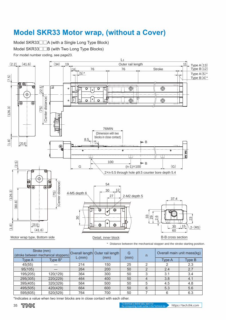
Model SKR33 Motor wrap, (without a Cover)Model SKR33□□A (with a Single Long Type Block)Model SKR33□□B (with Two Long Type Blocks)For model number coding, see page23.
Outer rail length
StrokeType A(13)Type B(12)Type A(5)*Type B(4)*
76MIN
(Dimension with two blocks in close contact)
B-B cross section
* Distance between the mechanical stopper and the stroke starting position.
(Center distance)
(C
en
ter
dis
tan
ce)
Detail, inner blockMotor wrap type, Bottom side
4-M5 depth 62-M2 depth 5
2×n-5.5 through hole φ9.5 counter bore depth 5.4
L1
11
(16) 76 76
(5)*
19(34)
(126.3)
(7.5)
(20.8)
(41.6)(2.2)
(1.8)
B
B2
1530
60
37.4
2.629
23
2-(R5)
(75)
(22.5)
33
(1.8)
(41.6)
(1
26
.3)
(20.8)
(2
.5)
(8
0.8) (75)
54
1230
27
30
100
G (n-1)×100 (G)
8.5
Stroke (mm)(stroke between mechanical stoppers) Overall length
L1(mm)Outer rail length
(mm)G
(mm) n Overall main unit mass(kg)
Type A Type B* Type A Type B45(55) ― 214 150 25 2 2 2.395(105) ― 264 200 50 2 2.4 2.7
195(205) 120(129) 364 300 50 3 3.1 3.4295(305) 220(229) 464 400 50 4 3.8 4.1395(405) 320(329) 564 500 50 5 4.5 4.8495(505) 420(429) 664 600 50 6 5.3 5.6595(605) 520(529) 764 700 50 7 6 6.3
*Indicates a value when two inner blocks are in close contact with each other.

36
SKR
Options⇒page60
Model SKR33 Motor wrap (with a Cover)Model SKR33□□A (with a Single Long Type Block)Model SKR33□□B (with Two Long Type Blocks)For model number coding, see page23.
StrokeType A(24)Type B(23)Type A(5)*Type B(4)*
(Dimension with twoblocks in close contact)
B′-B′ cross section
* Distance between the mechanical stopper and the stroke starting position.
(C
en
ter
dis
tan
ce)
Detail, Top table
4-M5 depth 10
4-M2 depth 4(from the backside)
Motor wrap type, Bottom side
2×n1-M2.6 depth 3.5 (Same position on the opposite side)(Sensor rail mounting hole)
(4.2)
54 54(27)(5)*
B′
B′
76MIN
1530
60
2.63
1
48
86
642
3
2-(R5)
(1
26
.3)
(75)
1230
5
67
4(
6)
24.5
H (n1-1)×F (H)F2
0
Stroke (mm)(stroke between mechanical stoppers) Overall length
L1(mm)Outer rail length
(mm)H
(mm)F
(mm) n1Overall main unit mass(kg)
Type A Type B* Type A Type B45(55) ― 214 150 25 100 2 2.2 2.695(105) ― 264 200 50 100 2 2.6 3
195(205) 120(129) 364 300 50 200 2 3.4 3.8295(305) 220(229) 464 400 100 200 2 4.1 4.5395(405) 320(329) 564 500 50 200 3 4.9 5.3495(505) 420(429) 664 600 100 200 3 5.6 6595(605) 520(529) 764 700 50 200 4 6.4 6.8
*Indicates a value when two inner blocks are in close contact with each other.

37 To download a desired data, search for the corresponding model number in the Technical site. https://tech.thk.com
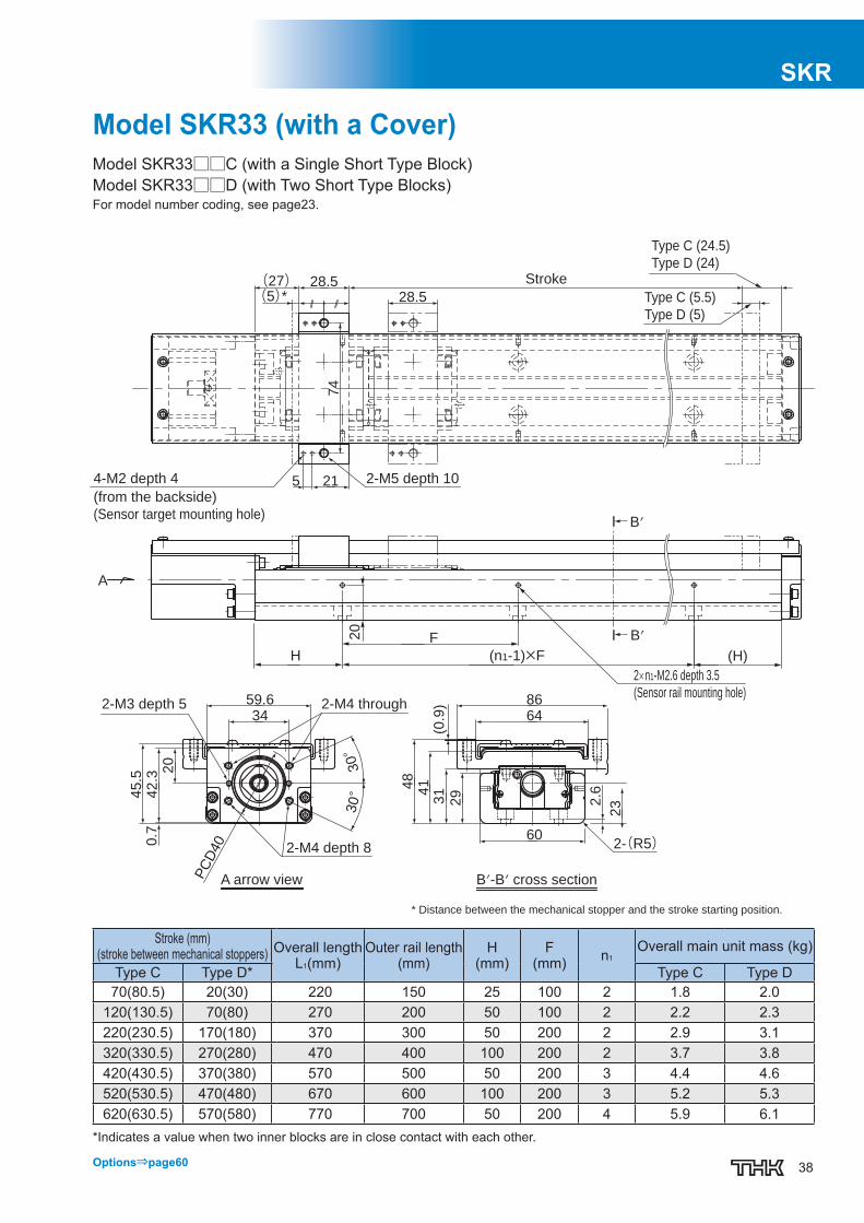
Model SKR33 (without a Cover)Model SKR33□□C (with a Single Short Type Block)Model SKR33□□D (with Two Short Type Blocks)For model number coding, see page23.
* Distance between the mechanical stopper and the stroke starting position.
B-B cross section C arrow viewA arrow view
Type C (5.5)
Type D (5)
Type C (13.5)
Type D (13)
Stroke
Outer rail length
2-M2 depth 5
2-M3 depth 4
2×n-5.5 through hole φ 9.5 counter bore depth 5.4
2-M5 depth 6
(Dimension with two
blocks in close contact)
2-M3 depth 5 2-M4 through
2-M4 depth 8
37.4
29
2333
602-(R5)30 15
2.6
34
59.6
PC
D40
43
.3
42
.60
.72
0.3
(G)
2227
169
10
2
100
G
3
30
11L1
50.5
28.5
8.5
59
φ2
8
φ3
0H
8
A C
(n-1)×100
50.5 MIN
30°
30°
φ8
h7
B
50.5(5)*(16)
B
43
.3
Stroke (mm)(stroke between mechanical stoppers)Overall length
L1(mm)Outer rail length
(mm)G
(mm) n Overall main unit mass (kg)
Type C Type D* Type C Type D70(80.5) 20(30) 220 150 25 2 1.6 1.8
120(130.5) 70(80) 270 200 50 2 2.0 2.1220(230.5) 170(180) 370 300 50 3 2.7 2.8320(330.5) 270(280) 470 400 50 4 3.4 3.6420(430.5) 370(380) 570 500 50 5 4.1 4.3520(530.5) 470(480) 670 600 50 6 4.8 5.0620(630.5) 570(580) 770 700 50 7 5.5 5.7
*Indicates a value when two inner blocks are in close contact with each other.
38
SKR
Options⇒page60
Model SKR33 (with a Cover)Model SKR33□□C (with a Single Short Type Block)Model SKR33□□D (with Two Short Type Blocks)For model number coding, see page23.
2×n1-M2.6 depth 3.5
(Sensor rail mounting hole)
H (H)
F
(n1-1)×F
* Distance between the mechanical stopper and the stroke starting position.
Type C (24.5)
Type D (24)
Type C (5.5)
Type D (5)
Stroke
A arrow view B′-B′ cross section
2-M3 depth 5 2-M4 through
2-M4 depth 8
(from the backside)
(Sensor target mounting hole)
4-M2 depth 4 2-M5 depth 10
48
31
29
232
.641
6459.634
20
86
602-(R5)
PC
D400
.74
5.5
42
.3
28.528.5
(27)(5)*
74
215
(0.9
)
30°
30°
A
B′
B′
20
Stroke (mm)(stroke between mechanical stoppers) Overall length
L1(mm)Outer rail length
(mm)H
(mm)F
(mm) n1Overall main unit mass (kg)
Type C Type D* Type C Type D70(80.5) 20(30) 220 150 25 100 2 1.8 2.0
120(130.5) 70(80) 270 200 50 100 2 2.2 2.3220(230.5) 170(180) 370 300 50 200 2 2.9 3.1320(330.5) 270(280) 470 400 100 200 2 3.7 3.8420(430.5) 370(380) 570 500 50 200 3 4.4 4.6520(530.5) 470(480) 670 600 100 200 3 5.2 5.3620(630.5) 570(580) 770 700 50 200 4 5.9 6.1
*Indicates a value when two inner blocks are in close contact with each other.

39 To download a desired data, search for the corresponding model number in the Technical site. https://tech.thk.com
Model SKR33 Motor wrap, (without a Cover)Model SKR33□□C (with a Single Short Type Block)Model SKR33□□D (with Two Short Type Blocks)For model number coding, see page23.
Outer rail length
Stroke
Type C(13.5)Type D(13)Type C(5.5)*Type D(5)*
(Dimension with twoblocks in close contact)
2-M2 depth 52-M5 depth 6
Detail, inner block
(C
en
ter
dis
tan
ce)
Motor wrap type, Bottom side B-B cross section
2×n-5.5 through hole φ9.5 counter bore depth 5.4
(126.3)
(7.5)
(20.8)
(41.6)(2.2)
(1.8)
L1
11
(16) 50.5 50.5
(5)*
19(34)
B
B
50.5MIN
8.5
2
2-(R5)
37.4
60
30 15
33
29
232.6
* Distance between the mechanical stopper and the stroke starting position.
(Center distance)
(75)
(22.5)
30
28.5
22.5
23
44.5
14.25
(8
0.8)
(1
.8)
(41.6)
(1
26
.3)
(20.8)
(2
.5)
(75)
100
G (n-1)×100 (G)
Stroke (mm)(stroke between mechanical stoppers) Overall length
L1(mm)Outer rail length
(mm)G
(mm) n Overall main unit mass(kg)
Type C Type D* Type C Type D70(80.5) 20(30) 214 150 25 2 1.9 2.1
120(130.5) 70(80) 264 200 50 2 2.3 2.5220(230.5) 170(180) 364 300 50 3 3 3.2320(330.5) 270(280) 464 400 50 4 3.7 3.9420(430.5) 370(380) 564 500 50 5 4.4 4.6520(530.5) 470(480) 664 600 50 6 5.1 5.3620(630.5) 570(580) 764 700 50 7 5.8 6
*Indicates a value when two inner blocks are in close contact with each other.

40
SKR
Options⇒page60
Model SKR33 Motor wrap (with a Cover)Model SKR33□□C (with a Single Short Type Block)Model SKR33□□D (with Two Short Type Blocks)For model number coding, see page23.
2×n1-M2.6 depth 3.5(Same position on the opposite side)(Sensor rail mounting hole)
(n1-1)×FF
H
20
(H)
(Dimension with twoblocks in close contact)
Stroke
Type C(24.5)Type D(24)Type C(5.5)*Type D(5)*
B′-B′ cross sectionMotor wrap type, Bottom side
(4.2)
B′
B′
50.5MIN
28.5 28.5(27)(5)*
86
(0.9)
48
41
31
1530
60
64
2-(R5)
2.6
23
* Distance between the mechanical stopper and the stroke starting position.
2-M5 depth 10
74
5
14.25
(6)
6
21
(1
30
.6)
Detail, Top table
4-M2 depth 4(from the backside)
Stroke (mm)(stroke between mechanical stoppers) Overall length
L1(mm)Outer rail length
(mm)H
(mm)F
(mm) n1Overall main unit mass(kg)
Type C Type D* Type C Type D70(80.5) 20(30) 214 150 25 100 2 2.1 2.4
120(130.5) 70(80) 264 200 50 100 2 2.5 2.8220(230.5) 170(180) 364 300 50 200 2 3.2 3.5320(330.5) 270(280) 464 400 100 200 2 4 4.3420(430.5) 370(380) 564 500 50 200 3 4.7 5520(530.5) 470(480) 664 600 100 200 3 5.5 5.8620(630.5) 570(580) 764 700 50 200 4 6.2 6.5
*Indicates a value when two inner blocks are in close contact with each other.
41 To download a desired data, search for the corresponding model number in the Technical site. https://tech.thk.com
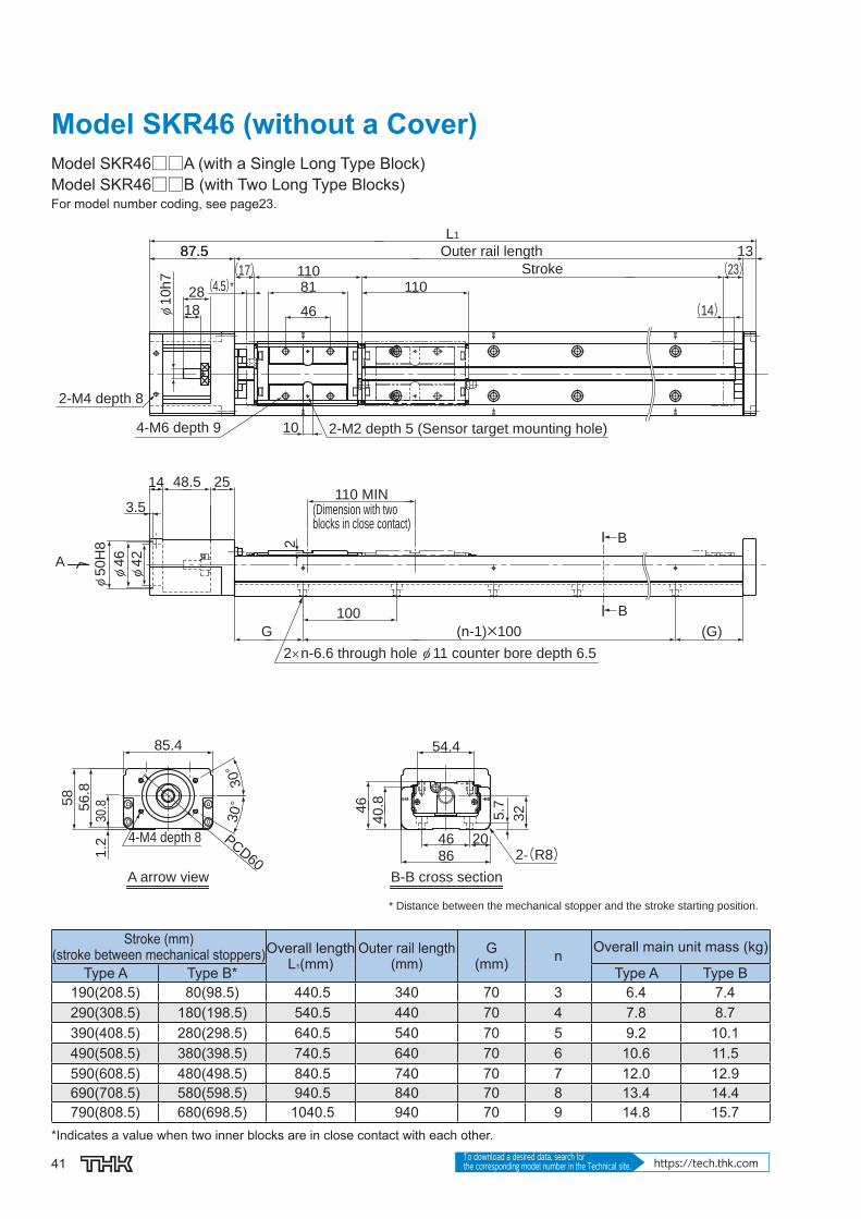
Model SKR46 (without a Cover)Model SKR46□□A (with a Single Long Type Block)Model SKR46□□B (with Two Long Type Blocks)For model number coding, see page23.
* Distance between the mechanical stopper and the stroke starting position.
A arrow view B-B cross section
Stroke
Outer rail length
4-M6 depth 9
2-M4 depth 8
2-M2 depth 5 (Sensor target mounting hole)
2×n-6.6 through hole φ 11 counter bore depth 6.5
(Dimension with two blocks in close contact)
4-M4 depth 8
54.4
46
2046
86
40
.8
325.7
13
81110
110
L1
10
46
(4.5)*(17)
87.587.5
18
28
φ1
0h
7
(23)
(14)
(G)
2514 48.5
2
100
G
A
110 MIN
(n-1)×100
B
B
φ4
2
φ5
0H
8
3.5
φ4
6
85.4
PCD60
30°
30°5
8
56
.8
30.8
1.2
2-(R8)
Stroke (mm)(stroke between mechanical stoppers)Overall length
L1(mm)Outer rail length
(mm)G
(mm) n Overall main unit mass (kg)
Type A Type B* Type A Type B190(208.5) 80(98.5) 440.5 340 70 3 6.4 7.4290(308.5) 180(198.5) 540.5 440 70 4 7.8 8.7390(408.5) 280(298.5) 640.5 540 70 5 9.2 10.1490(508.5) 380(398.5) 740.5 640 70 6 10.6 11.5590(608.5) 480(498.5) 840.5 740 70 7 12.0 12.9690(708.5) 580(598.5) 940.5 840 70 8 13.4 14.4790(808.5) 680(698.5) 1040.5 940 70 9 14.8 15.7
*Indicates a value when two inner blocks are in close contact with each other.

42
SKR
Options⇒page60
Model SKR46 (with a Cover)Model SKR46□□A (with a Single Long Type Block)Model SKR46□□B (with Two Long Type Blocks)For model number coding, see page23.
29
(4.5)*
* Distance between the mechanical stopper and the stroke starting position.
Stroke
A arrow view B′-B′ cross section
4-M4 depth 8
4-M6 depth 12
4-M5 depth 104-M2.6 depth 5 (from the backside)
(Sensor target mounting hole)
2×n1-M2.6 depth 4
(Sensor rail mounting hole)
A
68
56
100
88
86
43
32
40
.8
81(31.5)81
30
46
5
112
(1.8
)
5.7
B′
B′
10
0
(14)(37.5)
PCD60
1.2
56.8
85.4
30°
30°
64
30.8
200
(H)(n1-1)×200H
2-(R8)
Stroke (mm)(stroke between mechanical stoppers)Overall length
L1(mm)Outer rail length
(mm)H
(mm) n1Overall main unit mass (kg)
Type A Type B* Type A Type B190(208.5) 80(98.5) 440.5 340 70 2 7.1 8.3290(308.5) 180(198.5) 540.5 440 20 3 8.6 9.8390(408.5) 280(298.5) 640.5 540 70 3 10.0 11.3490(508.5) 380(398.5) 740.5 640 20 4 11.5 12.7590(608.5) 480(498.5) 840.5 740 70 4 13.0 14.2690(708.5) 580(598.5) 940.5 840 20 5 14.5 15.7790(808.5) 680(698.5) 1040.5 940 70 5 16.0 17.2
*Indicates a value when two inner blocks are in close contact with each other.

43 To download a desired data, search for the corresponding model number in the Technical site. https://tech.thk.com
Model SKR46 Motor wrap, (without a Cover)Model SKR46□□A (with a Single Long Type Block)Model SKR46□□B (with Two Long Type Blocks)For model number coding, see page23.
Outer rail length
Stroke
(Dimension with twoblocks in close contact)
2-M2 depth 5(Sensor target mounting hole)
4-M6 depth 9
Detail, inner block
(C
en
ter
dis
tan
ce)
B-B cross section
2×n-6.6 through hole φ11 counter bore depth 6.5
Motor wrap type, Bottom side
(30)(2)
(10)
(180.5)
(60)(2)L1
13
(23)(14)*
110110(17)(4.5)*
(44) 22
B
B
110MIN
10
2
2-(R8)
54.4
46
40.8
32
46
86
20
(Center distance)(
33)
(105)
* Distance between the mechanical stopper and the stroke starting position.
46
40.5
17.5
46
81
(1)
(2)
(1
80
.5)
(11
5.5)
(30)(60)
(105)
(70)(n-1)×10070
100
5.7
Stroke (mm)(stroke between mechanical stoppers) Overall length
L1(mm)Outer rail length
(mm) n Overall main unit mass(kg)
Type A Type B* Type A Type B190(208.5) 80(98.5) 419 340 3 7.4 8.4290(308.5) 180(198.5) 519 440 4 8.8 9.8390(408.5) 280(298.5) 619 540 5 10.2 11.2490(508.5) 380(398.5) 719 640 6 11.6 12.6590(608.5) 480(498.5) 819 740 7 13 14690(708.5) 580(598.5) 919 840 8 14.4 15.4790(808.5) 680(698.5) 1019 940 9 15.8 16.8
*Indicates a value when two inner blocks are in close contact with each other.
44
SKR
Options⇒page60
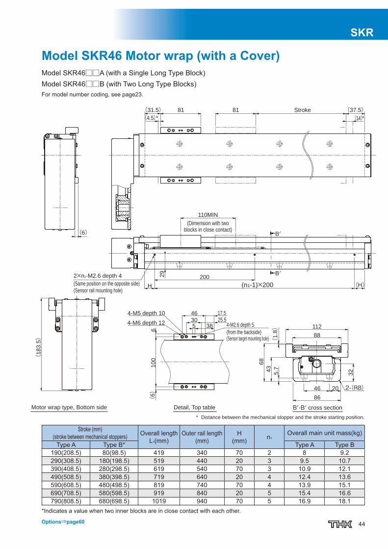
Model SKR46 Motor wrap (with a Cover)Model SKR46□□A (with a Single Long Type Block)Model SKR46□□B (with Two Long Type Blocks)For model number coding, see page23.
25.5
17.5
Stroke
(Dimension with twoblocks in close contact)
* Distance between the mechanical stopper and the stroke starting position.
4-M6 depth 12 4-M2.6 depth 5
(from the backside)(Sensor target mounting hole)
4-M5 depth 10
Detail, Top table B′-B′ cross sectionMotor wrap type, Bottom side
2×n1-M2.6 depth 4
(Same position on the opposite side)
(Sensor rail mounting hole)
(6)
(37.5)(14)*
(31.5)(4.5)*
8181
B′
B′
110MIN
2-(R8)
(1
.8)
43
68
112
88
32
46 20
86
(1
83
.5)
5 3830
46
10
06
(6)
200
H (n1-1)×200 (H)
29
5.7
Stroke (mm)(stroke between mechanical stoppers) Overall length
L1(mm)Outer rail length
(mm)H
(mm) n1Overall main unit mass(kg)
Type A Type B* Type A Type B190(208.5) 80(98.5) 419 340 70 2 8 9.2290(308.5) 180(198.5) 519 440 20 3 9.5 10.7390(408.5) 280(298.5) 619 540 70 3 10.9 12.1490(508.5) 380(398.5) 719 640 20 4 12.4 13.6590(608.5) 480(498.5) 819 740 70 4 13.9 15.1690(708.5) 580(598.5) 919 840 20 5 15.4 16.6790(808.5) 680(698.5) 1019 940 70 5 16.9 18.1
*Indicates a value when two inner blocks are in close contact with each other.
45 To download a desired data, search for the corresponding model number in the Technical site. https://tech.thk.com
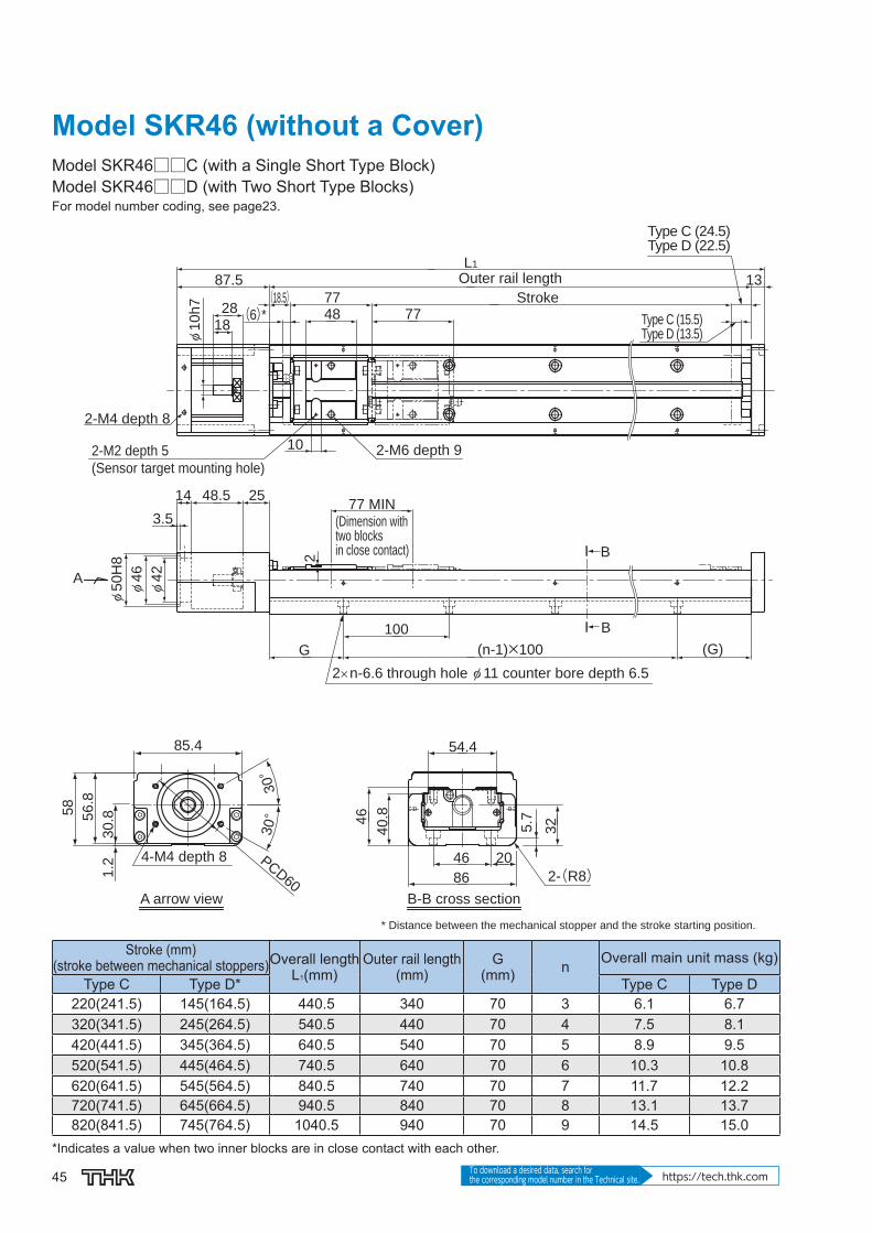
Model SKR46 (without a Cover)Model SKR46□□C (with a Single Short Type Block)Model SKR46□□D (with Two Short Type Blocks)For model number coding, see page23.
* Distance between the mechanical stopper and the stroke starting position.
A arrow view B-B cross section
Type C (24.5)Type D (22.5)
Type C (15.5)Type D (13.5)
Stroke
2-M2 depth 5
(Sensor target mounting hole)
2-M4 depth 8
2-M6 depth 9
Outer rail length
(Dimension with two blocks in close contact)
4-M4 depth 8
2×n-6.6 through hole φ 11 counter bore depth 6.5
54.4
20
5.7
86
46
46
40.8
32
(G)
2548.5
18
28
14
3.5
φ4
2
φ4
6
2
100
G
A
(18.5)13
L1
777748
87.5
10
(n-1)×100
77 MIN
φ1
0h
7
B
B
(6)*
85.4
PCD60
30°
30°5
8
56
.8
30
.81
.2φ
50
H8
2-(R8)
Stroke (mm)(stroke between mechanical stoppers)Overall length
L1(mm)Outer rail length
(mm)G
(mm) n Overall main unit mass (kg)
Type C Type D* Type C Type D220(241.5) 145(164.5) 440.5 340 70 3 6.1 6.7320(341.5) 245(264.5) 540.5 440 70 4 7.5 8.1420(441.5) 345(364.5) 640.5 540 70 5 8.9 9.5520(541.5) 445(464.5) 740.5 640 70 6 10.3 10.8620(641.5) 545(564.5) 840.5 740 70 7 11.7 12.2720(741.5) 645(664.5) 940.5 840 70 8 13.1 13.7820(841.5) 745(764.5) 1040.5 940 70 9 14.5 15.0
*Indicates a value when two inner blocks are in close contact with each other.

46
SKR
Options⇒page60
Model SKR46 (with a Cover)Model SKR46□□C (with a Single Short Type Block)Model SKR46□□D (with Two Short Type Blocks)For model number coding, see page23.
Type C (39)
Type D (37)
Type C (15.5)
Type D (13.5)
* Distance between the mechanical stopper and the stroke starting position.
A arrow view B′-B′ cross section
4-M2.6 depth 5
(from the backside)
(Sensor target mounting hole)
4-M4 depth 8
2-M6 depth 12
Stroke
2×n1-M2.6 depth 4
(Sensor rail mounting hole)
43
32
5668
40
.8
112
88
86
5.7
A
48
48
(33)(6)*
5 35.5
(1.8
)
B′
B′
10
0
PCD60
1.2
56.8
85.4
30°
30°
64
30.8
29
(n1-1)×200
200
H (H)
2-(R8)
Stroke (mm)(stroke between mechanical stoppers)Overall length
L1(mm)Outer rail length
(mm)H
(mm) n1Overall main unit mass (kg)
Type C Type D* Type C Type D220(241.5) 145(164.5) 440.5 340 70 2 6.6 7.4320(341.5) 245(264.5) 540.5 440 20 3 8.1 8.9420(441.5) 345(364.5) 640.5 540 70 3 9.6 10.3520(541.5) 445(464.5) 740.5 640 20 4 11.0 11.8620(641.5) 545(564.5) 840.5 740 70 4 12.5 13.3720(741.5) 645(664.5) 940.5 840 20 5 14 14.8820(841.5) 745(764.5) 1040.5 940 70 5 15.5 16.3
*Indicates a value when two inner blocks are in close contact with each other.

47 To download a desired data, search for the corresponding model number in the Technical site. https://tech.thk.com
Model SKR46 Motor wrap, (without a Cover)Model SKR46□□C (with a Single Short Type Block)Model SKR46□□D (with Two Short Type Blocks)For model number coding, see page23.
Outer rail length
Type C(24.5)Type D(22.5)
Type C(15.5)*Type D(13.5)*
Stroke
(Dimension with twoblocks in close contact)
B-B cross section
2-M2 depth 52-M6 depth 9
Detail, inner block
(C
en
ter
dis
tan
ce)
Motor wrap type, Bottom side
2×n-6.6 through hole φ11 counter bore depth 6.5
(180.5)
(10)
(2)
(30)
(60)(2)L1
13
7777(18.5)(6)*
22(44)
B
77MIN10
2
2-(R8)
54.4
46
40
.8
5.7
32
46
86
20
* Distance between the mechanical stopper and the stroke starting position.
(Center distance)
(105)
(33)
24
46
48
38
(60)(30)
(2)
(1
80
.5)
(1)
(11
5.5) (105)
(70)(n-1)×10070
100 B
Stroke (mm)(stroke between mechanical stoppers) Overall length
L1(mm)Outer rail length
(mm) n Overall main unit mass(kg)
Type C Type D* Type C Type D220(241.5) 145(164.5) 419 340 3 7.1 7.7320(341.5) 245(264.5) 519 440 4 8.5 9.1420(441.5) 345(364.5) 619 540 5 9.9 10.5520(541.5) 445(464.5) 719 640 6 11.3 11.9620(641.5) 545(564.5) 819 740 7 12.7 13.3720(741.5) 645(664.5) 919 840 8 14.1 14.7820(841.5) 745(764.5) 1019 940 9 15.5 16.1
*Indicates a value when two inner blocks are in close contact with each other.

48
SKR
Options⇒page60
Model SKR46 Motor wrap (with a Cover)Model SKR46□□C (with a Single Short Type Block)Model SKR46□□D (with Two Short Type Blocks)For model number coding, see page23.
Type C(39)Type D(37)Stroke
Type C(15.5)*Type D(13.5)*
(Dimension with twoblocks in close contact)
B′-B′ cross section
2-M6 depth 12
4-M2.6 depth 5(from the backside)(Sensor target mounting hole)
Detail, Top tableMotor wrap type, Bottom side
2×n1-M2.6 depth 4
(Same position on the opposite side)
(Sensor rail mounting hole)
(6)
4848(33)(6)*
B′
B′
77MIN
2-(R8)
5.7
(1
.4)
43
68
112
88
32
46 20
86
* Distance between the mechanical stopper and the stroke starting position.
(1
85
.5)
5 35.5
24
61
00
(6)
29
200
(n1-1)×200H (H)
Stroke (mm)(stroke between mechanical stoppers) Overall length
L1(mm)Outer rail length
(mm)H
(mm) n1Overall main unit mass(kg)
Type C Type D* Type C Type D220(241.5) 145(164.5) 419 340 70 2 7.5 8.3320(341.5) 245(264.5) 519 440 20 3 9 9.8420(441.5) 345(364.5) 619 540 70 3 10.5 11.3520(541.5) 445(464.5) 719 640 20 4 11.9 12.7620(641.5) 545(564.5) 819 740 70 4 13.4 14.2720(741.5) 645(664.5) 919 840 20 5 14.9 15.7820(841.5) 745(764.5) 1019 940 70 5 16.4 17.2
*Indicates a value when two inner blocks are in close contact with each other.

49 To download a desired data, search for the corresponding model number in the Technical site. https://tech.thk.com
Model SKR55 (without a Cover)Model SKR55□□A (with a Single Long Type Block)Model SKR55□□B (with Two Long Type Blocks)For model number coding, see page23.
50
95.2
128
128
15
(23)
(8)*
32
22
φ12h7
94
L1
50
8
274522
φ50H
8
1.5 20
128MIN
150
G (n-1)×100 (G)
32
100
2-(C3)
65
55
40
25503
99
78
45°
45°
72
71.5
31.5
0.5
PC
D70
B
B
A
* Distance between the mechanical stopper and the stroke starting position.
Stroke
Outer rail length
2×n-9 through hole φ 14 counter bore depth 8
4-M3 depth 6
4-M8 depth 12
(Dimension with two
blocks in close contact)
4-M5 depth 10
Type A (29)
Type B (21)Type A (18)
Type B (10)
A arrow view B-B cross section
Stroke (mm) (stroke between mechanical stoppers)Overall length
L1(mm)Outer rail length
(mm)G
(mm) n Overall main unit mass (kg)
Type A Type B* Type A Type B800 (826) 680 (698) 1089 980 40 7 20.8 22.7900 (926) 780 (798) 1189 1080 15 8 22.6 24.5
1000 (1026) 880 (898) 1289 1180 65 8 24.4 26.31100 (1126) 980 (998) 1389 1280 40 9 26.1 281200 (1226) 1080 (1098) 1489 1380 15 10 27.9 29.8
*Indicates a value when two inner blocks are in close contact with each other.

50
SKR
Options⇒page60
Model SKR55 (with a Cover)Model SKR55□□A (with a Single Long Type Block)Model SKR55□□B (with Two Long Type Blocks)For model number coding, see page23.
(0.9)
80
44
32
100 2-(C3)
124
B′
B′
95
9278
99
31.5
0.5
71.5
72
PCD70 4
5°
45°
50
95.2
95.2(8)*
(39.4)
8
110
A
27 200
H (H)(n1-1)×200
* Distance between the mechanical stopper and the stroke starting position.
Stroke
4-M8 through 4-M3 depth 6 (from the backside)
(Sensor target mounting hole)
4-M5 depth 10
Type A (45.4)
Type B (37.4)
Type A (18)
Type B (10)
B′-B′ cross sectionA arrow view
2×n1-M2.6 depth 4
(Sensor rail mounting hole)
Stroke (mm) (stroke between mechanical stoppers)Overall length
L1(mm)Outer rail length
(mm)H
(mm) n1Overall main unit mass (kg)
Type A Type B* Type A Type B800 (826) 680 (698) 1089 980 90 5 23.8 27.6900 (926) 780 (798) 1189 1080 40 6 25.7 29.5
1000 (1026) 880 (898) 1289 1180 90 6 27.6 31.41100 (1126) 980 (998) 1389 1280 40 7 29.5 33.31200 (1226) 1080 (1098) 1489 1380 90 7 31.4 35.2
*Indicates a value when two inner blocks are in close contact with each other.
51 To download a desired data, search for the corresponding model number in the Technical site. https://tech.thk.com
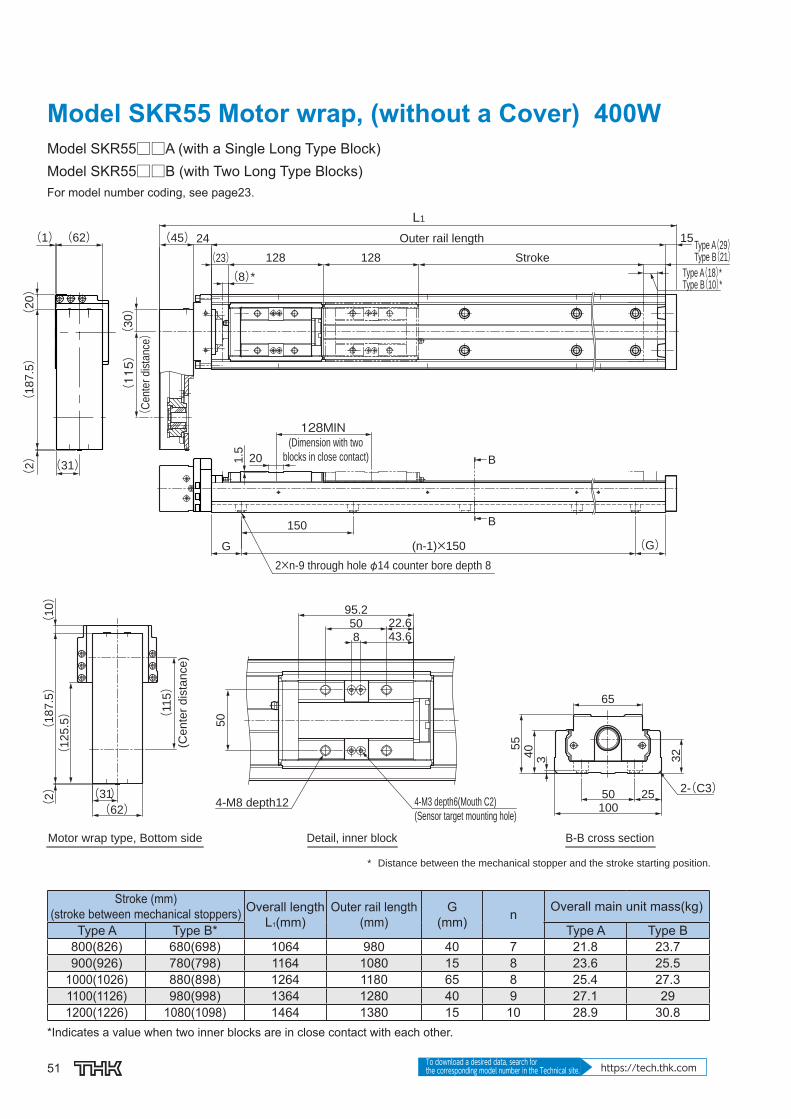
Model SKR55 Motor wrap, (without a Cover) 400WModel SKR55□□A (with a Single Long Type Block)Model SKR55□□B (with Two Long Type Blocks)For model number coding, see page23.
* Distance between the mechanical stopper and the stroke starting position.
Type A(29)Type B(21)
Type A(18)*Type B(10)*
Stroke
Outer rail length
2×n-9 through hole φ14 counter bore depth 8
(C
ente
r dis
tance)
128MIN(Dimension with two
blocks in close contact)
B-B cross sectionDetail, inner blockMotor wrap type, Bottom side
4-M3 depth6(Mouth C2)
(Sensor target mounting hole)4-M8 depth12
(Cente
r dis
tance)
(8)*(23) 128128
15(45)L1
24
(30)
(115)
G
150
(n-1)×150 (G)
B
B
1.5 20
32
100
2-(C3)
65
55
40
2550
3
50
95.222.65043.68
(125.5)
(187.5)
(10)
(2) (31)
(62)
(115)
(187.5)
(20)
(1)(62)
(2) (31)
Stroke (mm)(stroke between mechanical stoppers) Overall length
L1(mm)Outer rail length
(mm)G
(mm) n Overall main unit mass(kg)
Type A Type B* Type A Type B800(826) 680(698) 1064 980 40 7 21.8 23.7900(926) 780(798) 1164 1080 15 8 23.6 25.5
1000(1026) 880(898) 1264 1180 65 8 25.4 27.31100(1126) 980(998) 1364 1280 40 9 27.1 291200(1226) 1080(1098) 1464 1380 15 10 28.9 30.8
*Indicates a value when two inner blocks are in close contact with each other.

52
SKR
Options⇒page60
Model SKR55 Motor wrap (with a Cover) 400WModel SKR55□□A (with a Single Long Type Block)Model SKR55□□B (with Two Long Type Blocks)For model number coding, see page23.
(0.9)
80
44
3 32
100
2550 2-(C3)
12495
2×n1-M2.6 depth 4(Same position on the opposite side)
(Sensor rail mounting hole)
B′-B′ cross sectionDetail, Top tableMotor wrap type, Bottom side
* Distance between the mechanical stopper and the stroke starting position.
4-M8 depth36(through)
4-M3 depth6(from the backside)
(Sensor target mounting hole)
128MIN
(Dimension with two
blocks in close contact)
Type A(45.4)Type B(37.4)Type A(18)*Type B(10)*
Stroke
(205.5)
850
43.6
7110
(7)
22.6
B′
B′H (n1-1)×200 (H)
200 27
95.2 95.2
(8)*(39.4)
(17)
Stroke (mm)(stroke between mechanical stoppers) Overall
lengthL1(mm)Outer rail length
(mm)H
(mm) n1Overall main unit mass(kg)
Type A Type B* Type A Type B800(826) 680(698) 1064 980 90 5 24.8 28.6900(926) 780(798) 1164 1080 40 6 26.7 30.5
1000(1026) 880(898) 1264 1180 90 6 28.6 32.41100(1126) 980(998) 1364 1280 40 7 30.5 34.31200(1226) 1080(1098) 1464 1380 90 7 32.4 36.2
*Indicates a value when two inner blocks are in close contact with each other.

53 To download a desired data, search for the corresponding model number in the Technical site. https://tech.thk.com
Model SKR55 Motor wrap, (without a Cover) 750WModel SKR55□□A (with a Single Long Type Block)Model SKR55□□B (with Two Long Type Blocks)For model number coding, see page23.
4-M8 depth12 4-M3 depth6(Mouth C2)
* Distance between the mechanical stopper and the stroke starting position.
(Sensor target mounting hole)
B-B cross sectionDetail, inner blockMotor wrap type, Bottom side
(Ce
nte
r d
ista
nce
)
Outer rail length
StrokeType A(29)Type B(21)Type A(18)*Type B(10)*
2×n-9 through hole φ14 counter bore depth 8
128MIN(Dimension with two
blocks in close contact)
(Cente
r dis
tance
)
32
100
2-(C3)
65
55
40
2550
3
50
95.2
22.650
43.68
(141)
(2)
(204)
(9)
(41)(82)
(120)
B
B
15
128 128
241.5 20
(45)
L1
(8)*(23)
(G)(n-1)×150
150
G
(41)
(32)(10)
(1)(71)
(15)
(208)
(2)
(120)
(35)
Stroke (mm)(stroke between mechanical stoppers) Overall length
L1(mm)Outer rail length
(mm)G
(mm) n Overall main unit mass(kg)
Type A Type B* Type A Type B800(826) 680(698) 1064 980 40 7 22.2 24.1900(926) 780(798) 1164 1080 15 8 24 25.9
1000(1026) 880(898) 1264 1180 65 8 25.8 27.71100(1126) 980(998) 1364 1280 40 9 27.5 29.41200(1226) 1080(1098) 1464 1380 15 10 29.3 31.2
*Indicates a value when two inner blocks are in close contact with each other.

54
SKR
Options⇒page60
Model SKR55 Motor wrap (with a Cover) 750WModel SKR55□□A (with a Single Long Type Block)Model SKR55□□B (with Two Long Type Blocks)For model number coding, see page23.
StrokeType A(45.4)Type B(37.4)Type A(18)*Type B(10)*
(Dimension with two
blocks in close contact)
4-M8 depth36(through)
4-M3 depth6(from the backside)
(Sensor target mounting hole)
B′-B′ cross sectionDetail, Top tableMotor wrap type, Bottom side
2×n1-M2.6 depth 4(Same position on the opposite side)
(Sensor rail mounting hole)
B′
B′
95.2 95.2(39.4)
128MIN
(8)*
H
200
(n1-1)×200 (H)
(0.9)
80
44
3 32
100
2550 2-(C3)
124
95
850
43.6
7110
(7)
22.6
(221)
* Distance between the mechanical stopper and the stroke starting position.
(8)
Stroke (mm)(stroke between mechanical stoppers) Overall
lengthL1(mm)Outer rail length
(mm)H
(mm) n1Overall main unit mass(kg)
Type A Type B* Type A Type B800(826) 680(698) 1064 980 90 5 25.2 29900(926) 780(798) 1164 1080 40 6 27.1 30.9
1000(1026) 880(898) 1264 1180 90 6 29 32.81100(1126) 980(998) 1364 1280 40 7 30.9 34.71200(1226) 1080(1098) 1464 1380 90 7 32.8 36.6
*Indicates a value when two inner blocks are in close contact with each other.

55 To download a desired data, search for the corresponding model number in the Technical site. https://tech.thk.com
Model SKR65 (without a Cover)Model SKR65□□A (with a Single Long Type Block)Model SKR65□□B (with Two Long Type Blocks)For model number coding, see page23.
2-(C2)
65
47
5.2
130
70 30
38
87
128102
45°
82
37
45°
1PCD10
0 PCD
90
30°
30°
83
35
(G)(n-1)×100G
150
145MIN
1.4
20
3530
3.5
φ60
φ70H
8
8
L1
φ15h7
100
(19.2)
145
145
110
70
70
16 (4.8)*
29
18
B
B
A
Outer rail length
Stroke
4-M6 depth 124-M6 depth 12
* Distance between the mechanical stopper and the stroke starting position.
(Dimension with two
blocks in close contact)
4-M3 depth 6 (Sensor target mounting hole)
Type A (25.8)
Type B (30.8)
Type A (15.2)
Type B (20.2)
A arrow view B-B cross section
2×n-11 through hole φ 17.5 counter bore depth 9.5
Stroke (mm) (stroke between mechanical stoppers)Overall length
L1(mm)Outer rail length
(mm)G
(mm) n Overall main unit mass (kg)
Type A Type B* Type A Type B790 (810) 640 (665) 1098 980 40 7 30.2 33.2990 (1010) 840 (865) 1298 1180 65 8 35.4 38.41190 (1210) 1040 (1065) 1498 1380 90 9 40.6 43.61490 (1510) 1340 (1365) 1798 1680 90 11 48.3 51.3
*Indicates a value when two inner blocks are in close contact with each other.

56
SKR
Options⇒page60
Model SKR65 (with a Cover)Model SKR65□□A (with a Single Long Type Block)Model SKR65□□B (with Two Long Type Blocks)For model number coding, see page23.
2-(C2)
38
130
92
52
(1.5) 170
129
45°
45°
30°
30°
128
102
PCD
100
PCD
90
83
82
37
8
150
(4.8)*
(36.7) 110
11050
B′
B′
1
A
30
2×n1-M2.6 depth 4 (Sensor rail mounting hole)
* Distance between the mechanical stopper and the stroke starting position.
4-M3 depth 6 (from the backside)
(Sensor target mounting hole)
4-M8 through
4-M6 depth 124-M6 depth 12
Stroke
Type A (43.3)
Type B (48.3)
Type A (15.2)
Type B (20.2)
A arrow view B′-B′ cross section
(H)(n1-1)×200H
200
Stroke (mm) (stroke between mechanical stoppers)Overall length
L1(mm)Outer rail length
(mm)H
(mm) n1Overall main unit mass (kg)
Type A Type B* Type A Type B790 (810) 640 (665) 1098 980 90 5 33.4 40.1990 (1010) 840 (865) 1298 1180 90 6 38.9 45.61190 (1210) 1040 (1065) 1498 1380 90 7 44.3 511490 (1510) 1340 (1365) 1798 1680 40 9 52.4 59.1
*Indicates a value when two inner blocks are in close contact with each other.
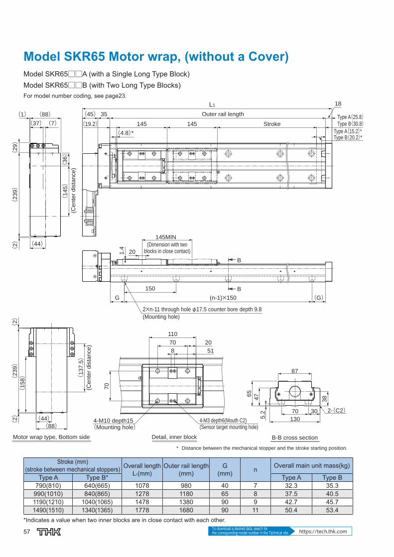
57 To download a desired data, search for the corresponding model number in the Technical site. https://tech.thk.com
Model SKR65 Motor wrap, (without a Cover)Model SKR65□□A (with a Single Long Type Block)Model SKR65□□B (with Two Long Type Blocks)For model number coding, see page23.
Type A(25.8)Type B(30.8)
Type A(15.2)*Type B(20.2)*
Stroke
Outer rail length
2×n-11 through hole φ17.5 counter bore depth 9.8
(Mounting hole)
(Dimension with twoblocks in close contact)
B-B cross section
(Ce
nte
r d
ista
nce
)
(Ce
nte
r d
ista
nce
)
4-M10 depth15(Mounting hole)
4-M3 depth6(Mouth C2)(Sensor target mounting hole)
Detail, inner blockMotor wrap type, Bottom side
145145(19.2)
L1 18
(45) 35
(4.8)*
B
B
145MIN
201.4
(G)150
G (n-1)×150
65
47
5.2
130
70 30 2-(C2)
38
87
* Distance between the mechanical stopper and the stroke starting position.
(2)
(2
39)
(2)
(1
58)
(44)(88)
(1
37
.5)
110
70
8
20
51
70
(1
45)
(3
6)
(88)(37)
(1)
(2)
(7)
(2
39)
(44)
(2
9)
Stroke (mm)(stroke between mechanical stoppers) Overall length
L1(mm)Outer rail length
(mm)G
(mm) n Overall main unit mass(kg)
Type A Type B* Type A Type B790(810) 640(665) 1078 980 40 7 32.3 35.3
990(1010) 840(865) 1278 1180 65 8 37.5 40.51190(1210) 1040(1065) 1478 1380 90 9 42.7 45.71490(1510) 1340(1365) 1778 1680 90 11 50.4 53.4
*Indicates a value when two inner blocks are in close contact with each other.
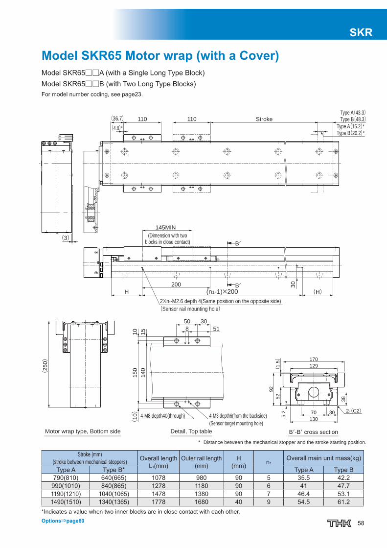
58
SKR
Options⇒page60
Model SKR65 Motor wrap (with a Cover)Model SKR65□□A (with a Single Long Type Block)Model SKR65□□B (with Two Long Type Blocks)For model number coding, see page23.
(3)
Type A(43.3)Type B(48.3)
Type A(15.2)*Type B(20.2)*
Stroke
(Dimension with twoblocks in close contact)
B′-B′ cross section
* Distance between the mechanical stopper and the stroke starting position.
2×n1-M2.6 depth 4(Same position on the opposite side)
(Sensor rail mounting hole)
Detail, Top tableMotor wrap type, Bottom side
4-M3 depth6(from the backside)4-M8 depth40(through)
(Sensor target mounting hole)
110110(36.7)(4.8)*
B′
B′
2-(C2)130
70 30
38
170
129
(1.5)
52
92
5.2
145MIN
30
(H)(n1-1)×200H
200
(250)
50 30
8 51
(10)
150
10
140
15
Stroke (mm)(stroke between mechanical stoppers) Overall length
L1(mm)Outer rail length
(mm)H
(mm) n1Overall main unit mass(kg)
Type A Type B* Type A Type B790(810) 640(665) 1078 980 90 5 35.5 42.2990(1010) 840(865) 1278 1180 90 6 41 47.71190(1210) 1040(1065) 1478 1380 90 7 46.4 53.11490(1510) 1340(1365) 1778 1680 40 9 54.5 61.2
*Indicates a value when two inner blocks are in close contact with each other.

59
Mass of Moving Element
Table14 shows the mass of the inner block and top table of model SKR.
Table14 Mass of the Inner Block and Top table of SKR Unit: kg
Model No.Long nut block types (A) Short nut block types (C)
Inner block Top table Inner block Top tableSKR20 0.064 0.038 — —SKR26 0.153 0.074 — —SKR33 0.31 0.13 0.17 0.07SKR46 0.91 0.34 0.57 0.20SKR55 1.9 1.9 — —SKR65 3.0 3.5 — —
SKR SKRCaged Ball LM Guide Actuator Model SKR

60
SKR
OptionsSensor
Optional proximity sensors and photo sensors are available for model SKR. Models equipped with a sensor are also provided with a dedicated sensor rail/sensor dog.If the stroke is less than 70 mm, 2 sensor fl ag and 2 sensor rail will be attached.
[Example of Installation]
Table15 With/without a sensor
Symbol Description Type Accessory0 None — —1 With sensor rail — Mounting screws, sensor rail
2 Photo Sensor* [3 units] EE-SX671 (Omron Corp.) Mounting screw/nut, detecting plate, sensor rail, mounting plate, connector (EE-1001)
6 Photo Sensor* [3 units] EE-SX674 (Omron Corp.) Mounting screw/nut, detecting plate, sensor rail, mounting plate, connector (EE-1001)
7 Proximity Sensor N.O. contact [3 units] APM-D3A1-001 (Azbil Corp.) Mounting screw/nut, detecting plate, sensor railB Proximity Sensor N.C. contact [3 units] APM-D3B1-003 (Azbil Corp.) Mounting screw/nut, detecting plate, sensor rail
E Proximity Sensor N.O. contact [1 unit] N.C. contact [2 units]
APM-D3A1-001APM-D3B1-003 (Azbil Corp.) Mounting screw/nut, detecting plate, sensor rail
H Proximity Sensor N.O. contact [3 units] GX-F12A (Panasonic Industrial Devices SUNX Co., Ltd.) Mounting screw/nut, detecting plate, sensor railL Proximity Sensor N.C. contact [3 units] GX-F12B (Panasonic Industrial Devices SUNX Co., Ltd.) Mounting screw/nut, detecting plate, sensor rail
J Proximity Sensor N.O. contact [1 unit] N.C. contact [2 units]
GX-F12AGX-F12B (Panasonic Industrial Devices SUNX Co., Ltd.) Mounting screw/nut, detecting plate, sensor rail
M Proximity Sensor N.O. contact [1 unit] N.C. contact [2 units]
GX-F12A-PGX-F12B-P (Panasonic Industrial Devices SUNX Co., Ltd.) Mounting screw/nut, detecting plate, sensor rail
N.O. contact: normally open contactN.C. contact: normally closed contact*The photo-sensors can be switched between ON when lit and ON when unlit.
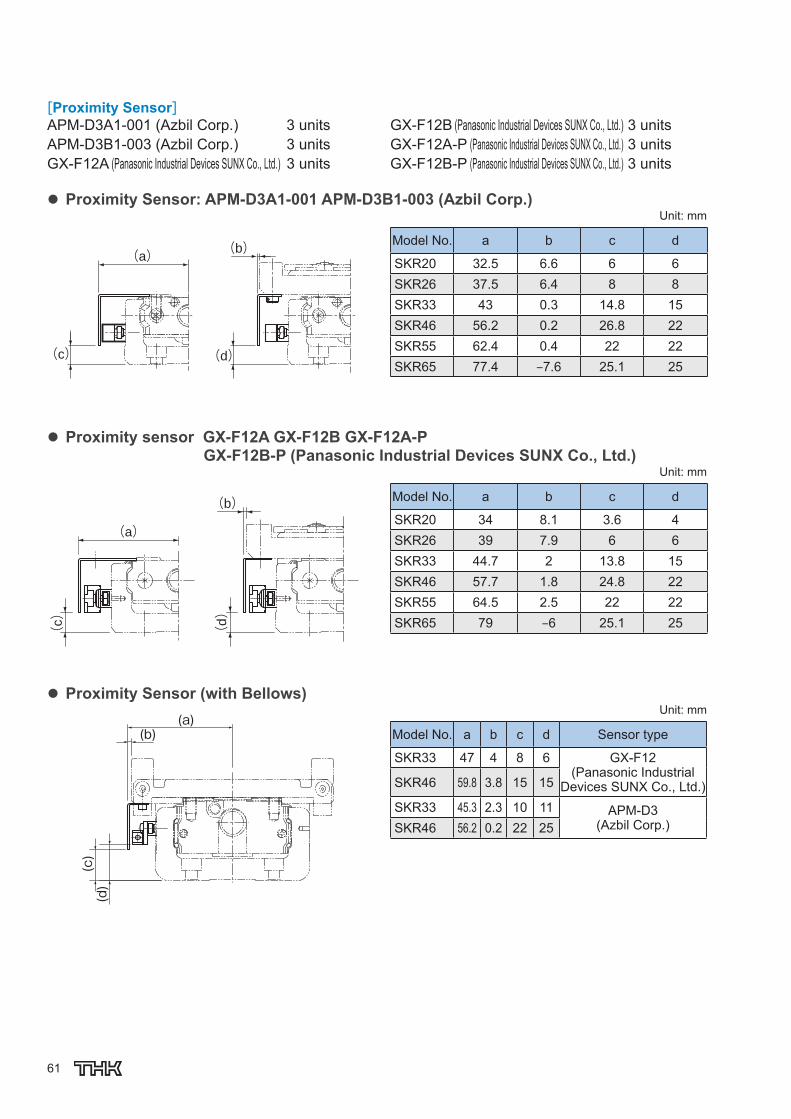
61
[Proximity Sensor]APM-D3A1-001 (Azbil Corp.) 3 unitsAPM-D3B1-003 (Azbil Corp.) 3 unitsGX-F12A (Panasonic Industrial Devices SUNX Co., Ltd.) 3 units
GX-F12B (Panasonic Industrial Devices SUNX Co., Ltd.) 3 unitsGX-F12A-P (Panasonic Industrial Devices SUNX Co., Ltd.) 3 unitsGX-F12B-P (Panasonic Industrial Devices SUNX Co., Ltd.) 3 units
Proximity Sensor: APM-D3A1-001 APM-D3B1-003 (Azbil Corp.)
(a)
(c) (d)
(b)
Unit: mm
Model No. a b c d
SKR20 32.5 6.6 6 6SKR26 37.5 6.4 8 8SKR33 43 0.3 14.8 15SKR46 56.2 0.2 26.8 22SKR55 62.4 0.4 22 22SKR65 77.4 ‒7.6 25.1 25
Proximity sensor GX-F12A GX-F12B GX-F12A-P GX-F12B-P (Panasonic Industrial Devices SUNX Co., Ltd.)
(a)
(c)
(d)
(b)
Unit: mm
Model No. a b c d
SKR20 34 8.1 3.6 4SKR26 39 7.9 6 6SKR33 44.7 2 13.8 15SKR46 57.7 1.8 24.8 22SKR55 64.5 2.5 22 22SKR65 79 ‒6 25.1 25
Proximity Sensor (with Bellows)
(b)(a)
(c)
(d)
Unit: mm
Model No. a b c d Sensor type
SKR33 47 4 8 6 GX-F12(Panasonic Industrial
Devices SUNX Co., Ltd.)SKR46 59.8 3.8 15 15
SKR33 45.3 2.3 10 11 APM-D3(Azbil Corp.)SKR46 56.2 0.2 22 25

62
SKR[Photo Sensor] EE-SX671 (Omron Corp.) 3 units EE-SX674 (Omron Corp.) 3 unitsConnector EE-1001 (Omron Corp.) 3 unitsNote) The connector is an appended article.
Photo Sensor: EE-SX671 (Omron Corp.)
(e)(f)
(i)(j)
(g)
(h)
Unit: mm
Model No. e f g h i j
SKR20 41 53.8 15 9.4 0.9 9.5SKR26 45.9 58.7 14.9 11.4 2.9 11.5SKR33 51.1 63.6 8.3 18.8 7.4 19.5SKR46 64.1 76.6 8.3 29.8 16.4 26.5SKR55 70.7 83.5 8.6 24.5 13.6 25SKR65 85.5 98.5 0.6 28.1 16.6 28
Photo Sensor: EE-SX674 (Omron Corp.)
(e)(f) (g)
(i)
(j)(h)
Unit: mm
Model No. e f g h i j
SKR20 38.3 44.8 12.5 10.9 0.6 11SKR26 43.3 49.7 12.5 12.9 2.6 13SKR33 45.9 52.1 3.3 17.8 7.1 20SKR46 58.9 65.1 3.2 28.8 16.1 27SKR55 63.5 70.5 1.5 24.5 13.1 24SKR65 79 85.5 ‒6 28.6 16.1 28
Photo Sensor (with Bellows)
(b)
(d)
(c)
(a)Unit: mm
Model No. a b c d Sensor type
SKR33 63.6 8.3 14.5 2.4 EE-SX671(Omron Corp.)SKR46 76.6 8.3 26.5 16.4
SKR33 52.1 3.3 18 5.1 EE-SX674(Omron Corp.)SKR46 65.1 3.2 27 16.1

63
[Sensor Rail]The sensor rail can be attached alone.
Sensor rail
5.8
4.3 8
5
2.4 0.8
A LH
Unit: mm
Model No. Stroke* Outer rail length H A L
SKR2030 100
10 43111
80 150 161130 200 211
SKR26
60 150
12 54
161110 200 211160 250 261210 300 311
SKR33
45 150
20 61
14695 200 196
195 300 296295 400 396395 500 496495 600 596595 700 696
SKR46
190 340
29 89.5
336290 440 436390 540 536490 640 636590 740 736690 840 836790 940 936
SKR55
800 980
27 96
976900 1080 1076
1000 1180 11761100 1280 12761200 1380 1376
SKR65
790 980
30 102
976990 1180 11761190 1380 13761490 1680 1676
* Indicates stroke length when one long-type inner block is incorporated.

64
SKR
Intermediate Flange[Motor Used and Applicable Intermediate Flanges for Model SKR]Several types of intermediate fl anges for mounting motors are available for model SKR. Specify an intermediate fl ange that matches the motor used.Each intermediate fl ange is made of steel and provided with THK AP-C treatment, a surface treatment that provides excellent corrosion resistance.
Table16 Table of Motors Used and Corresponding Intermediate Flanges
Motor type Rated output
Flange size SKR20 SKR26 SKR33 SKR46 SKR55 SKR65
AC
ser
vo m
otor
Yask
awa
Ele
ctric
-Ⅴ
min
i SGMMV-A1 10W□25
AN AN — — — —SGMMV-A2 20W AN AN — — — —SGMMV-A3 30W AN AN — — — —
-7
SGM7J-A5 50W
□40
AQ AQ AQ AQ — —SGM7A-A5 AQ AQ AQ AQ — —SGM7J-01 100W — — AQ AQ — —SGM7J-01 — — AQ AQ — —SGM7J-C2 150W — — — AQ — —SGM7A-C2 — — — AQ — —SGM7J-02 200W
□60
— — — AV — —SGM7J-02 — — — AV — —SGM7J-04 400W — — — AV — —SGM7J-04 — — — AV — —SGM7J-06 600W — — — — — —SGM7J-06 — — — — — —SGM7J-08 750W □80 — — — — — —SGM7J-08 — — — — — —
-Ⅴ
SGMJV-A5 50W
□40
AQ AQ AQ AQ — —SGMAV-A5 AQ AQ AQ AQ — —SGMJV-01 100W — — AQ AQ — —SGMAV-01 — — AQ AQ — —SGMAV-C2 150W — — — AQ — —SGMJV-02 200W
□60
— — — AV A0 AVSGMAV-02 — — — AV A0 AVSGMJV-04 400W — — — AV A0 AVSGMAV-04 — — — AV A0 AVSGMAV-06 550W — — — — A0 AVSGMJV-08 750W □80 — — — — AZ AZSGMAV-08 — — — — AZ AZ
-Ⅲ
SGMAS-A5 50W □40 AQ AQ AQ AQ — —SGMAS-01 100W — — AQ AQ — —SGMPS-01
□60— — — AV A0 AV
SGMAS-02 200W — — — AV A0 AVSGMAS-04 400W — — — AV A0 AVSGMPS-02 200W
□80— — — — AZ A0
SGMPS-04 400W — — — — AZ A0SGMAS-08 750W — — — — AZ AZ
Mits
ubis
hi E
lect
ric
ME
LSE
RV
O
J2-J
r HC-AQ013 10W□28
AM AM — — — —HC-AQ023 20W AM AM — — — —HC-AQ033 30W AM AM — — — —
J4
HG-KR053 50W□40
AQ AQ AQ AQ — —HG-MR053 AQ AQ AQ AQ — —HG-KR13 100W — — AQ AQ — —HG-MR13 — — AQ AQ — —HG-KR23 200W
□60
— — — AV A0 AVHG-MR23 — — — AV A0 AVHG-KR43 400W — — — AV A0 AVHG-MR43 — — — AV A0 AVHG-KR73 750W □80 — — — — AZ AZHG-MR73 — — — — AZ AZ
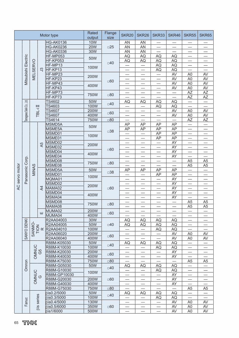
65
Motor type Rated output
Flange size SKR20 SKR26 SKR33 SKR46 SKR55 SKR65
AC
ser
vo m
otor
Mits
ubis
hi E
lect
ric
ME
LSE
RV
O
J3HG-AK0136 10W
□25AN AN — — — —
HG-AK0236 20W AN AN — — — —HG-AK0336 30W AN AN — — — —HF-MP053 50W
□40
AQ AQ AQ AQ — —HF-KP053 AQ AQ AQ AQ — —HF-MP13 100W — — AQ AQ — —HF-KP13 — — AQ AQ — —HF-MP23 200W
□60
— — — AV A0 AVHF-KP23 — — — AV A0 AVHF-MP43 400W — — — AV A0 AVHF-KP43 — — — AV A0 AVHF-MP73 750W □80 — — — — AZ AZHF-KP73 — — — — AZ AZ
Tamaga
wa Sei
ki Co.,
Ltd.
TBL-
i Ⅱ
TS4602 50W □40 AQ AQ AQ AQ — —TS4603 100W — — AQ AQ — —TS4607 200W □60 — — — AV A0 AVTS4607 400W — — — AV A0 AVTS4614 750W □80 — — — — AZ AZ
Pan
ason
ic C
orp.
MIN
AS
A5
MSMD5A 50W□38
AP AP AP AP — —MSME5A AP AP AP AP — —MSMD01 100W — — AP AP — —MSME01 — — AP AP — —MSMD02 200W
□60
— — — AY — —MSME02 — — — AY — —MSMD04 400W — — — AY — —MSME04 — — — AY — —MSMD08 750W □80 — — — — A5 A5MSME08 — — — — A5 A5
A4
MSMD5A 50W □38 AP AP AP AP — —MSMD01 100W — — AP AP — —MQMA01
□60
— — — AY — —MSMD02 200W — — — AY — —MAMA02 — — — AY — —MSMD04 400W — — — AY — —MSMA04 — — — AY — —MSMD08 750W □80 — — — — A5 A5MAMA08 — — — — A5 A5
E MUMA02 200W □60 — — — — — —MUMA04 400W — — — — — —
SANY
O DE
NKI
SA
NM
O-
TIO
NR
R2AA04003 30W□40
AQ AQ AQ AQ — —R2AA04005 50W AQ AQ AQ AQ — —R2AA04010 100W — — AQ AQ — —R2AA06020 200W □60 — — — AV A0 AVR2AA06040 400W — — — AV A0 AV
Om
ron
OM
NU
CG
5
R88M-K05030 50W □40 AQ AQ AQ AQ — —R88M-K10030 100W — — AQ AQ — —R88M-K20030 200W □60 — — — AY — —R88M-K40030 400W — — — AY — —R88M-K75030 750W □80 — — — — A5 A5
OM
NU
CG
R88M-G05030 50W □40 AQ AQ AQ AQ — —R88M-G10030 100W — — AQ AQ — —R88M-GP10030
□60— — — AY — —
R88M-G20030 200W — — — AY — —R88M-G40030 400W — — — AY — —R88M-G75030 750W □80 — — — — A5 A5
Fanu
c
is
serie
s is0.2/5000 50W □40 AQ AQ AQ AQ — —is0.3/5000 100W — — AQ AQ — —is0.4/5000 130W
□60— — — AV A0 AV
is0.5/6000 350W — — — AV A0 AVis1/6000 500W — — — AV A0 AV
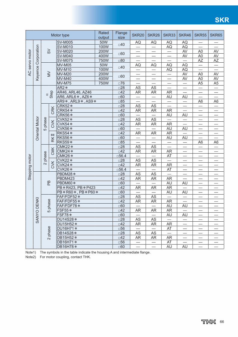
66
SKR
Motor type Rated output
Flange size SKR20 SKR26 SKR33 SKR46 SKR55 SKR65
AC
ser
vo m
otor
Key
ence
Cor
pora
tion
SV
SV-M005 50W □40 AQ AQ AQ AQ — —SV-M010 100W — — AQ AQ — —SV-M020 200W □60 — — — AV A0 AVSV-M040 400W — — — AV A0 AVSV-M075 750W □80 — — — — AZ AZ
MV
MV-M05 50W □40 AQ AQ AQ AQ — —MV-M10 100W — — AQ AQ — —MV-M20 200W □60 — — — AV A0 AVMV-M40 400W — — — AV A0 AVMV-M75 750W □76 — — — — A5 A5
Ste
ppin
g m
otor
Orie
ntal
Mot
or
S
tep
AR2* □28 AS AS — — — —AR46, ARL46, AZ46 □42 AR AR AR — — —AR6, ARL6*, AZ6* □60 — — AU AU — —AR9*, ARL9*, AS9* □85 — — — — A6 A6
5 ph
ase
CR
K CRK52* □28 AS AS — — — —CRK54* □42 AR AR AR — — —CRK56* □60 — — AU AU — —
CV
K CVK52* □28 AS AS — — — —CVK54* □42 AR AR AR — — —CVK56* □60 — — AU AU — —
RKⅡ RKS54* □42 AR AR AR — — —
RKS56* □60 — — AU AU — —RKS59* □85 — — — — A6 A6
2 ph
ase CM
K CMK22* □28 AS AS — — — —CMK24* □42 AR AR AR — — —CMK26* □56.4 — — AT — — —
CVK
CVK22* □28 AS AS — — — —CVK24* □42 AR AR AR — — —CVK26* □56.4 — — AT — — —
SA
NY
O D
EN
KI
PB
PBDM28* □28 AS AS — — — —PBDM423 □42 AR AR AR — — —PBDM60* □60 — — AU AU — —PB*R423, PB*P423 □42 AR AR AR — — —PB*R60*, PB*P60* □60 — — AU AU — —
5 ph
ase
FAF/FDF52* □28 AS AS — — — —FAF/FDF55* □42 AR AR AR — — —FAF/FDF78* □60 — — AU AU — —FSF55* □42 AR AR AR — — —FSF78* □60 — — AU AU — —
2 ph
ase
DU14S28* □28 AS AS — — — —DU15H52* □42 AR AR AR — — —DU16H71* □56 — — AT — — —DB14S28* □28 AS AS — — — —DB15H52* □42 AR AR AR — — —DB16H71* □56 — — AT — — —DB16H78* □60 — — AU AU — —
Note1) The symbols in the table indicate the housing A and intermediate fl ange.Note2) For motor coupling, contact THK.
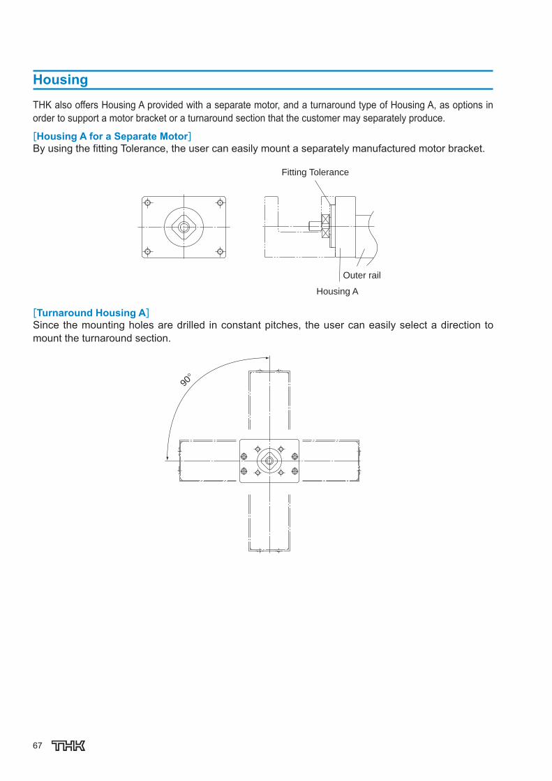
67
Housing
THK also offers Housing A provided with a separate motor, and a turnaround type of Housing A, as options in order to support a motor bracket or a turnaround section that the customer may separately produce.
[Housing A for a Separate Motor]By using the fi tting Tolerance, the user can easily mount a separately manufactured motor bracket.
Fitting Tolerance
Outer rail
Housing A
[Turnaround Housing A]Since the mounting holes are drilled in constant pitches, the user can easily select a direction to mount the turnaround section.
90°

68
SKR
Motor wrap model coding
Incase「R1」,「R2」,「R3」,「R4」,「R5」, or「R6」is selected at motor type.
Motor type, Motor wrap model codingMotor wrap type available for various type motorsPlease specify part code according to used motor
W Q − 08 D① ② ③ ④
①Motor wrap type W②Motor plate type Please refer to below chart (Motor/ Part coding chart)
③Specify Motor shaft diameter (mm) Please refer to below chart (Motor/ Part coding chart)
④Pulley mounitnig optionsK:Key wayD:Shaft fl at (D-cut)M:Friction bushing
Friction bushingKey way Shaft flat (D-cut)
Table17 Motor/ Part codingchart
Motor type Rated output
Flange size SKR20 SKR26 SKR33 SKR46 SKR55 SKR65
AC
ser
vo m
otor
Yask
awa
Ele
ctric
-Ⅴ
min
i SGMMV-A1 10W□25
WN-05D WN-05D — — — —SGMMV-A2 20W WN-05D WN-05D — — — —SGMMV-A3 30W WN-05D WN-05D — — — —
-7
SGM7J-A5 50W□40
WQ-08K WQ-08K WQ-08K, WQ-08M — — —SGM7A-A5 WQ-08K WQ-08K WQ-08K, WQ-08M — — —SGM7J-01 100W — — WQ-08K, WQ-08M — — —SGM7J-01 — — WQ-08K, WQ-08M — — —SGM7J-02 200W
□60
— — — WV-14M — —SGM7J-02 — — — WV-14M — —SGM7J-04 400W — — — WV-14M — —SGM7J-04 — — — WV-14M — —SGM7J-08 750W □80 — — — — — —SGM7J-08 — — — — — —
-Ⅴ
SGMJV-A5 50W□40
WQ-08K WQ-08K WQ-08K, WQ-08M — — —SGMAV-A5 WQ-08K WQ-08K WQ-08K, WQ-08M — — —SGMJV-01 100W — — WQ-08K, WQ-08M — — —SGMAV-01 — — WQ-08K, WQ-08M — — —SGMJV-02 200W
□60
— — — WV-14M — —SGMAV-02 — — — WV-14M — —SGMJV-04 400W — — — WV-14M WV-14M WV-14MSGMAV-04 — — — WV-14M WV-14M WV-14MSGMJV-08 750W □80 — — — — WZ-19M WZ-19MSGMAV-08 — — — — WZ-19M WZ-19M
-Ⅱ
SGMAH-A3 30W□40
— — WQ-06K, WQ-06M — — —SGMAH-A5 50W — — WQ-06K, WQ-06M — — —
SGMAH-01 100W — — WQ-08K, WQ-08M — — —
□60— — — — — —
SGMAH-02 200W — — — WV-14M — —SGMAH-04 400W — — — WV-14M — —SGMPH-02 200W
□80— — — — — —
SGMPH-04 400W — — — — — —SGMAH-08 750W — — — — — —

69
Motor type Rated output
Flange size SKR20 SKR26 SKR33 SKR46 SKR55 SKR65
AC
ser
vo m
otor
Mits
ubis
hi E
lect
ric
ME
LSE
RV
O
J2-J
r HC-AQ013 10W□28
WM-06D WM-06D — — — —HC-AQ023 20W WM-06D WM-06D — — — —HC-AQ033 30W WM-06D WM-06D — — — —
J4
HG-MR053 50W□40
WQ-08D WQ-08D WQ-08D, WQ-08M — — —HG-KR053 WQ-08D WQ-08D WQ-08D, WQ-08M — — —HG-MR13 100W — — WQ-08D, WQ-08M — — —HG-KR13 — — WQ-08D, WQ-08M — — —HG-MR23 200W
□60
— — — WV-14M — —HG-MR43 400W — — — WV-14M WV-14M WV-14MHG-KR23 200W — — — WV-14M — —HG-KR43 400W — — — WV-14M WV-14M WV-14MHG-MR73 750W □80 — — — — WZ-19M WZ-19MHG-KR73 — — — — WZ-19M WZ-19M
J3
HG-AK0136 10W□25
WN-05D WN-05D — — — —HG-AK0236 20W WN-05D WN-05D — — — —HG-AK0336 30W WN-05D WN-05D — — — —HF-MP053 50W
□40
WQ-08D WQ-08D WQ-08D, WQ-08M — — —HF-KP053 WQ-08D WQ-08D WQ-08D, WQ-08M — — —HF-MP13 100W — — WQ-08D, WQ-08M — — —HF-KP13 — — WQ-08D, WQ-08M — — —HF-MP23 200W
□60
— — — WV-14M — —HF-KP23 — — — WV-14M — —HF-MP43 400W — — — WV-14M WV-14M WV-14MHF-KP43 — — — WV-14M WV-14M WV-14MHF-MP73 750W □80 — — — — WZ-19M WZ-19MHF-KP73 — — — — WZ-19M WZ-19M
Tamaga
wa Sei
ki Co.,
Ltd.
TBL-
i Ⅱ
TS4602 50W □40 WQ-08D WQ-08D WQ-08D, WQ-08M — — —TS4603 100W — — WQ-08D, WQ-08M — — —TS4607 200W □60 — — — WV-14M — —TS4609 400W — — — WV-14M WV-14M WV-14MTS4614 750W □80 — — — — WZ-19M WZ-19M
Pan
ason
ic C
orp.
MIN
AS
A5 MSMD04 400W □60 — — — — WY-14M WY-14M
MSMD08 750W □80 — — — — W5-19M W5-19M
A4
MSMD5A 50W □38 WP-08K WP-08K WP-08K, WP-08M — — —MSMD01 100W — — WP-08K, WP-08M — — —MSMD02 200W □60 — — — WY-11M — —MSMD04 400W — — — WY-14M WY-14M WY-14MMQMA02 200W
□80— — — — — —
MQMA04 400W — — — — W5-14M W5-14MMSMD08 750W — — — — W5-19M W5-19M
SAN
YO D
ENKI
SANM
OTIO
N Q1 Q1AA06040D 400W □60 — — — — WV-14M WV-14M
R
R2AA04003 30W□40
— — WQ-06M — — —R2AA04005 50W — — WQ-08M — — —R2AA04010 100W — — WQ-08M — — —R2AA06020 200W □60 — — — WV-14M — —R2AA06040 400W — — — WV-14M — —
Om
ron
OM
NU
C G
5 R88M-K05030 50W □40 WQ-08K WQ-08K WQ-08K, WQ-08M — — —R88M-K10030 100W — — WQ-08K, WQ-08M — — —R88M-K20030 200W □60 — — — WY-11M — —R88M-K40030 400W — — — WY-14M WY-14M WY-14MR88M-K75030 750W □80 — — — — W5-19M W5-19M
Fanu
c
β is serie
s βis0.2/5000 50W □40 WQ-08K WQ-08K — — — —βis0.3/5000 100W — — — — — —
Keyenc
e Corp
oration
SV SV-M40 400W □60 — — — — WV-14M WV-14M
SV-M75 750W □80 — — — — WZ-19M WZ-19M
MV MV-M40 400W □60 — — — — WV-14M WV-14M
MV-M75 750W □76 — — — — WZ-16M WZ-16M
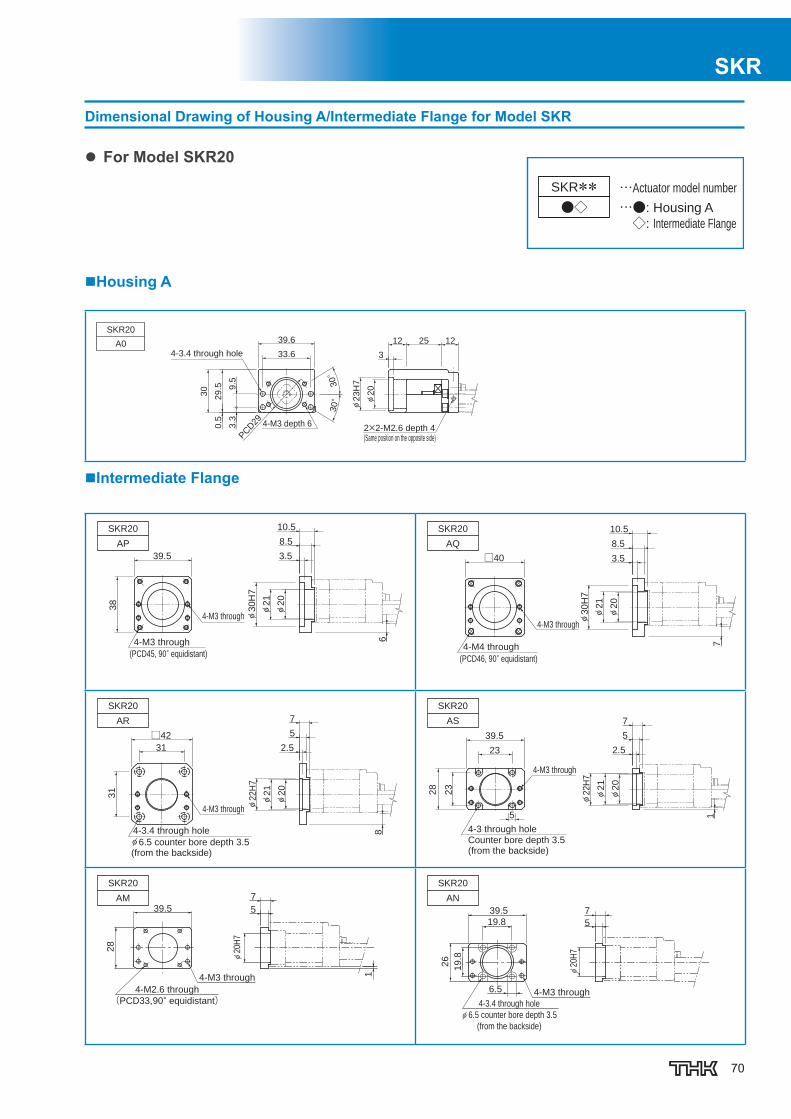
70
SKR
Dimensional Drawing of Housing A/Intermediate Flange for Model SKR
For Model SKR20
…●: Housing A
◇: Intermediate Flange
…Actuator model numberSKR**●◇
Housing A
Intermediate Flange
4-3.4 through hole
4-M3 depth 62×2-M2.6 depth 4(Same position on the opposite side)
SKR20
A0
33.6
39.6
3.3
9.5
30°
PCD29
29
.5
30
0.5
30°
12
3
25 12
φ2
0
φ2
3H
7
64-M3 through
(PCD45, 90° equidistant)
4-M3 through
SKR20
AP
39.5
38
3.5
8.5
10.5
φ2
0
φ2
1
φ3
0H
7
4-M4 through
(PCD46, 90° equidistant)
4-M3 through
SKR20
AQ
□40 3.5
8.5
10.5
φ2
0
φ2
1
φ3
0H
7
7
4-M3 through
4-3.4 through holeφ 6.5 counter bore depth 3.5(from the backside)
SKR20
AR
31
□42
31
2.5
5
7
φ2
0
φ2
1
φ22H
7
8
4-M2.6 through
(PCD33,90° equidistant)
4-M3 through
7
39.5 5
1
28
φ20
H7
SKR20
AM
4-3 through hole
Counter bore depth 3.5(from the backside)
4-M3 through
SKR20
AS
23
39.5
23
28
2.5
5
7
1
φ2
0
φ2
1
φ22H
7
5
4-M3 through
4-3.4 through holeφ 6.5 counter bore depth 3.5
(from the backside)
739.5
6.5
5
φ20
H7
26
19
.8
SKR20
AN
19.8

71
For Model SKR20
…□:Motor mounting plate
…Actuator model numberSKR**W□
No Motor Bracket Housing
4-M3 depth 6(PCD23.5, 90° equidistant)
Motor shaft strength to be invesitgated for motor wrap type. Please consult THK
SKR2020
29.5
12.5
0.5
39.6 8
12.5
1.5 12
∅17.5h7
0-0.018
∅4h
7-
0.01
2 0
Motor Wrap type (Motor mounting plate)
4-M3 through(PCD45, 90° equidistant)
4-M3 through
Thickness (t):8.5mm
38
39.5
9.5
9.5
33.6SKR26
WP
4-M4 through(PCD46, 90° equidistant)
4-M3 through
Thickness (t):8.5mm
33.6
9.5
10.5
40
40
SKR20WQ
4-M2.6 through(PCD33, 90° equidistant)
4-M3 through
Thickness (t):5mm
33.6
9.5
4.8
28
39.5SKR20WM
4-3.4 through hole Counter bore depth 3.5(PCD28, 90° equidistant)(from the backside)
4-M3 through
Thickness (t):5mm6.5
9.5
3.8
26
39.5
33.6SKR20
WN
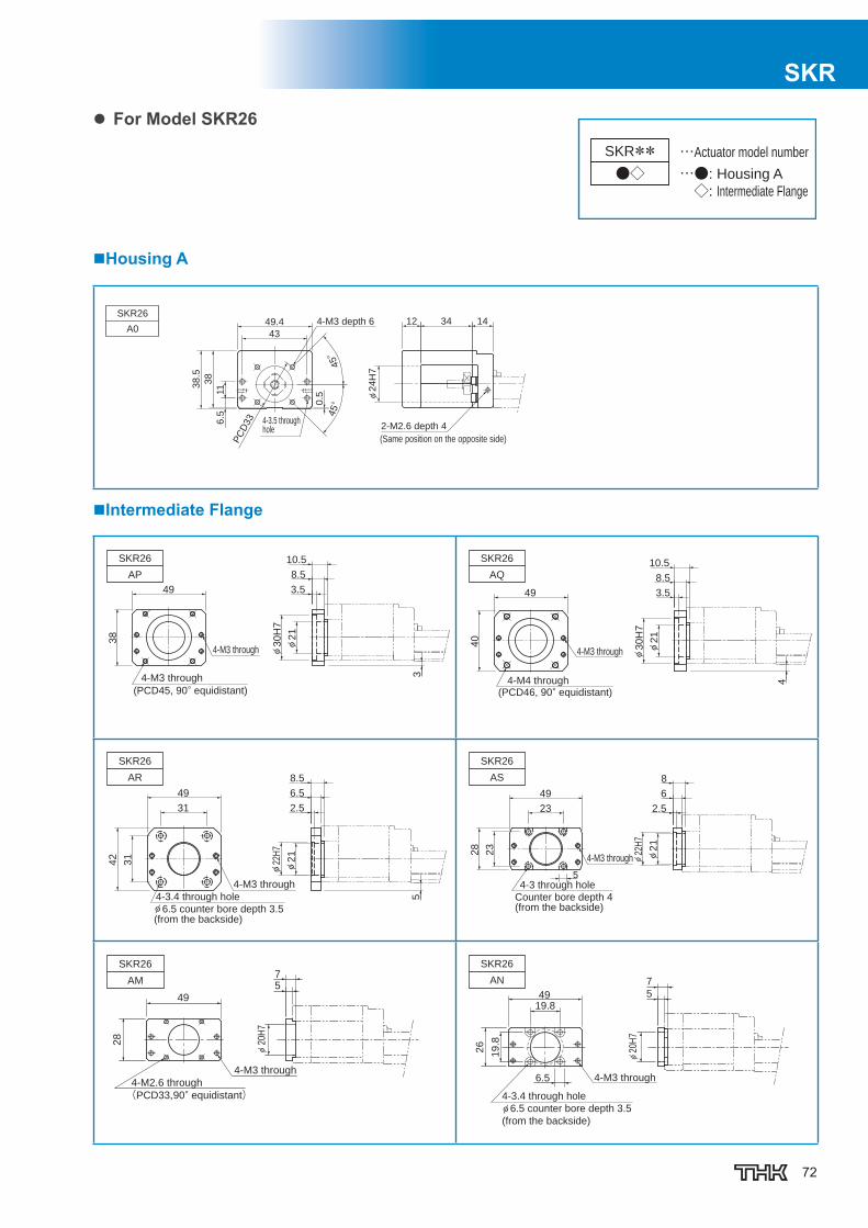
72
SKR
For Model SKR26
…●: Housing A
◇: Intermediate Flange
…Actuator model numberSKR**●◇
Housing A
Intermediate Flange
4-M3 depth 6
(Same position on the opposite side)
2-M2.6 depth 4 4-3.5 through hole
49.4
11
PC
D33
38
43
0.5
38
.5
6.5
45°
45°
φ2
4H
7
12 34 14SKR26
A0
4-M3 through
(PCD45, 90° equidistant)
4-M3 through
SKR26
AP
φ2
1
φ3
0H
7
3
49
38
8.5
10.5
3.5
4-M4 through(PCD46, 90° equidistant)
4-M3 through
SKR26
AQ
3.5
8.5
10.5
49
40
φ21
φ30H
7
4
4-3.4 through holeφ 6.5 counter bore depth 3.5(from the backside)
4-M3 through
SKR26
AR
2.5
6.5
8.5
φ21
φ22
H7
31
42
49
31
5
4-M3 through
4-3 through hole
Counter bore depth 4(from the backside)
SKR26
AS
23
49
23
28
2.5
6
8
φ2
1
φ22
H7
5
4-M3 through
4-3.4 through holeφ 6.5 counter bore depth 3.5
(from the backside)
7
549
6.5
26
19
.8
φ20
H7
SKR26
AN
19.8
4-M2.6 through
(PCD33,90° equidistant)
4-M3 through
75
49
28
φ20
H7
SKR26
AM

73
For Model SKR26
…□:Motor mounting plate
…Actuator model numberSKR**W□
No Motor Bracket Housing
4-M3 depth 6(PCD23.5, 90° equidistant)
Motor shaft strength to be invesitgated for motor wrap type. Please consult THK
SKR2620
15.5
380.
5
49.4 10
15
1.5 14
∅5h
7-
0.01
2
∅17.5h7
0-0.018
0
Motor Wrap type (Motor mounting plate)
4-M3 through(PCD45, 90° equidistant)
4-M3 through
Thickness (t):8.5mm
38
39.5
9.5
9.5
33.6SKR26
WP
4-M4 through(PCD46, 90° equidistant)
Thickness (t):8.5mm
4-M3 through
SKR26WQ 33.6
10.5
9.5
40
40
4-M3 through
4-M2.6 through(PCD33, 90° equidistant)
SKR26WM
Thickness (t):5mm
9.5
4.8
33.6
39.5
28
4-M3 through
4-3.4 through hole Counter bore depth 3.5
Thickness (t):5mm
(from the backside)
SKR26WN
6.5
26
9.5
3.8
39.5
33.6
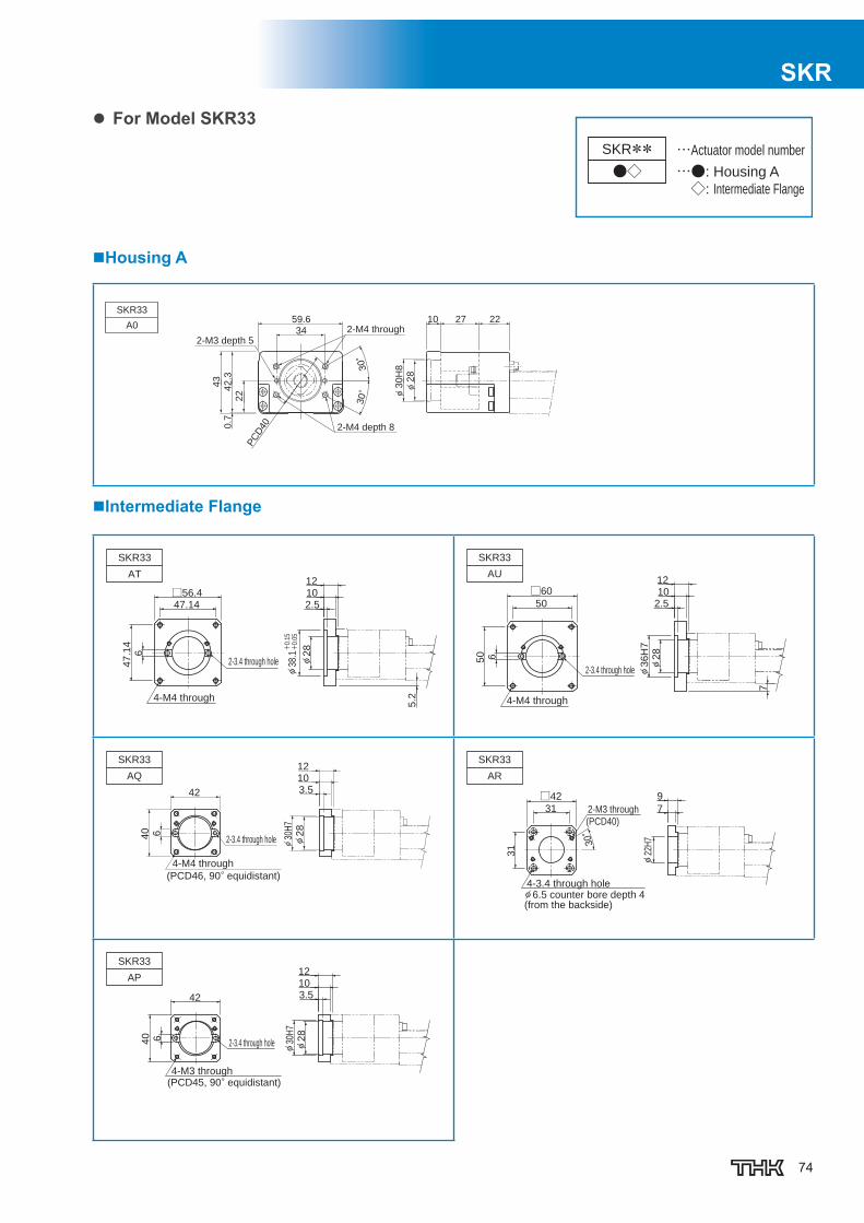
74
SKR
For Model SKR33
…●: Housing A
◇: Intermediate Flange
…Actuator model numberSKR**●◇
Housing A
Intermediate Flange
2-M3 depth 5
2-M4 through
2-M4 depth 8
222710
φ2
8
φ3
0H
8
59.6
34
30°
30°
22
42
.30
.7
43
PC
D40
SKR33
A0
4-M4 through
2-3.4 through hole
SKR33
AT
47.14□56.4
47
.14
2.51012
φ2
8
6
5.2
φ38
.1+
0.15
+0.
05
4-M4 through
2-3.4 through hole
SKR33
AU
50
□60
50
φ2
8
φ3
6H
7
2.51012
6
7
4-M4 through
(PCD46, 90° equidistant)
2-3.4 through hole
SKR33
AQ
42
40
3.51012
6
φ2
8
φ30
H7
4-3.4 through holeφ 6.5 counter bore depth 4(from the backside)
2-M3 through
(PCD40)
SKR33
AR
31
□42
31
30°
7
9
φ22
H7
4-M3 through(PCD45, 90° equidistant)
2-3.4 through hole
SKR33
AP
42
40
3.51012
φ2
8
φ30
H7
6

75
For Model SKR33
…□:Motor mounting plate
…Actuator model numberSKR**W□
No Motor Bracket Housing
4-M4 depth 8(heilisert 2D)
Motor shaft strength to be invesitgated for motor wrap type. Please consult THK
9
16
3 19
59.6
42.5
0.5
22.5
9
27
∅8h
7-
0.01
5
∅30
.4 0
27
SKR3340
Motor Wrap type (Motor mounting plate)
4-M3 through
4-M4 through(PCD46, 90° equidistant)
SKR33WQ
383
23
44
40
23
∅31
Thickness (t): mm
4-M3 through
4-M3 through(PCD45, 90° equidistant)
SKR33WP
383
23
∅31
40
23
44
Thickness (t): mm
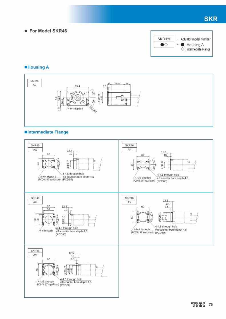
76
SKR
For Model SKR46
…●: Housing A
◇: Intermediate Flange
…Actuator model numberSKR**●◇
Housing A
Intermediate Flange
4-M4 depth 8
SKR46
A0
30.85
6.8
58
1.2
85.4
PCD60
30°
30° φ
42
3.514 2548.5
φ50H
8
4-M4 depth 6(PCD46, 90° equidistant)
4-4.5 through holeφ 8 counter bore depth 4.5
SKR46
AQ
1012.5
φ3
0H
7
30°
30°
62
53
(PCD60)4-M3 depth 6
(PCD45, 90° equidistant)
4-4.5 through holeφ 8 counter bore depth 4.5(PCD60)
SKR46
AP
1012.5
φ3
0H
7
30°
30°
53
62
4-M4 through4-4.5 through holeφ 8 counter bore depth 4.5(PCD60)
SKR46
AU
1012.5
φ3
6H
7
30°
30°
62
50
60
50
4-M4 through(PCD70, 90° equidistant)
4-4.5 through holeφ 8 counter bore depth 4.5(PCD60)
SKR46
AY
3.510
12.5
φ4
2
φ4
4
30°
30°
62
60
φ5
0H
7
4-M5 through(PCD70, 90° equidistant)
4-4.5 through holeφ 8 counter bore depth 4.5(PCD60)
SKR46
AV
3.510
12.5
φ4
2
φ4
4
φ5
0H
7
62
60 30°
30°

77
For Model SKR46
…□:Motor mounting plate
…Actuator model numberSKR**W□
Turnaround Housing A
4-M5 depth 10(heilisert 2D)
SKR4660
1.2
62.8
30.8
10.8
85.4
40 1828
3 22
∅10
h7-
0.01
5
∅40
.4 0
40
Motor Wrap type (Motor mounting plate)
4-M5 through
4-M5 through(PCD70, 90° equidistant)
SKR46WV
4.5
36.5
∅51
60
36
71 62
Thickness (t): mm
4-M5 through
4-M4 through(PCD70, 90° equidistant)
SKR46WY
4.5
36.5
∅51
71 62
6036
Thickness (t): mm
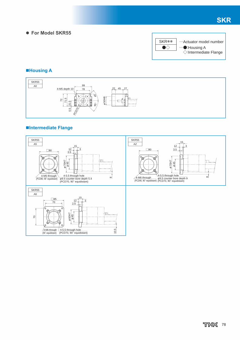
78
SKR
For Model SKR55SKR**●◇ …●:Housing A
◇:Intermediate Flange
…Actuator model number
Housing A
4-M5 depth 10
SKR55
A022 45 27
φ5
0H
8
99
78
PC
D70
72
71
.5
31
.50
.5
45°
45°
Intermediate Flange
(PCD70, 90° equidistant)φ9.5 counter bore depth 5.4
4-5.5 through hole
(PCD90, 90° equidistant)4-M5 through
SKR55
A5
φ7
0H
7
□80
φ4
5
33.512
15
8 4-M6 through
(PCD90, 90° equidistant)
4-5.5 through holeφ9.5 counter bore depth 9(PCD70, 90° equidistant)
SKR55
AZ3
15
3.5
12
φ45
φ70H
7
8
□80
(90° equidistant) (PCD70, 90° equidistant)4-M6 through 4-5.5 through hole
SKR55
A6
3
φ6
0H
7φ
45
10
.5
70
□85
2.5
15
12
70
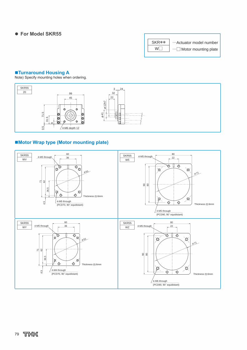
79
For Model SKR55
…□:Motor mounting plate
…Actuator model numberSKR**W□
Turnaround Housing ANote) Specify mounting holes when ordering.
4-M6 depth 12
SKR55
20
71.5
0.5
31.5
9
99
22
32
3 24
45
φ41φ
12h7
Motor Wrap type (Motor mounting plate)
4-M5 through
4-M5 through
(PCD70, 90° equidistant)
SKR55
WV
4.5
∅51
71
36.5
62
60
36
Thickness (t):6mm
4-M5 through
4-M5 through
Thickness (t):6mm
(PCD90, 90° equidistant)
SKR55
W5
∅71
90
80
80
22
4-M5 through
4-M4 through
(PCD70, 90° equidistant)
SKR55
WY
∅51
60
36
71
4.5
62
36.5
Thickness (t):6mm
4-M5 through
4-M6 through
(PCD90, 90° equidistant)
SKR55
WZ
∅71
90
80
80
22
Thickness (t):6mm
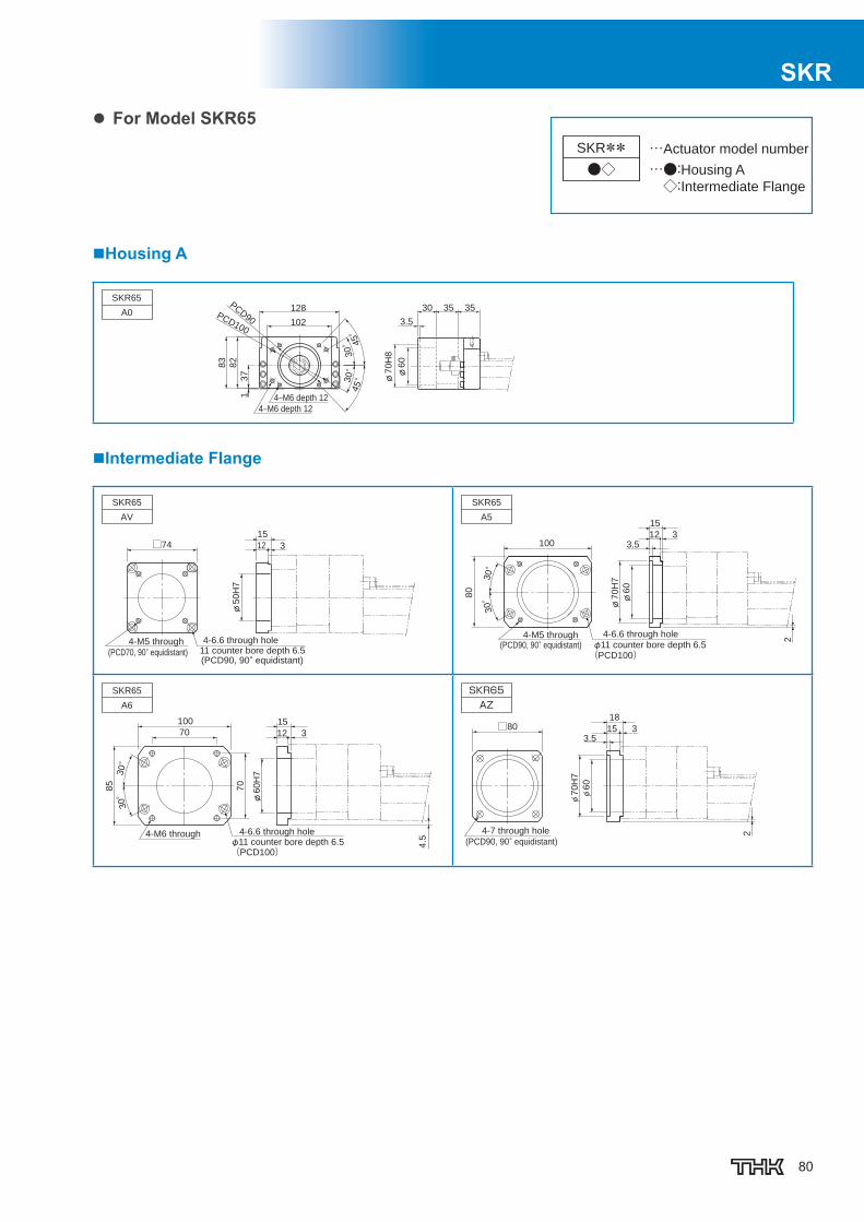
80
SKR
For Model SKR65
…●:Housing A
◇:Intermediate Flange
…Actuator model numberSKR**●◇
Housing A
4‒M6 depth 12
4‒M6 depth 12
SKR65
A030
3.5
35 35
φ7
0H
8
82
83
φ6
0
102
128PCD90
PCD100
30°
30°
45°
45°3
71
Intermediate Flange
11 counter bore depth 6.54-6.6 through hole
(PCD70, 90° equidistant)(PCD90, 90° equidistant)
4-M5 through
SKR65
AV
□74
φ5
0H
7
15
12 3
(PCD90, 90° equidistant)4-M5 through
φ11 counter bore depth 6.5
4-6.6 through hole
(PCD100)
SKR65
A5
100
80
2
φ7
0H
7φ
60
12 33.5
15
30°
30°
φ11 counter bore depth 6.54-6.6 through hole4-M6 through
SKR65
A6
φ6
0H
7
4.5
85
70
100
12 3
15
30°
30°
(PCD100)
70
4-7 through hole
(PCD90, 90° equidistant)
SKR65AZ
□80
φ6
0
φ7
0H
7
23.5
315
18
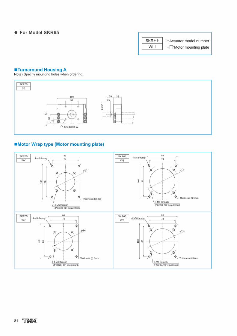
81
For Model SKR65
…□:Motor mounting plate
…Actuator model numberSKR**W□
Turnaround Housing ANote) Specify mounting holes when ordering.
182
37
16
16
29 35
φ15h7
12856
SKR65
30
4-M6 depth 12
Motor Wrap type (Motor mounting plate)
4-M5 through
4-M5 through
(PCD70, 90° equidistant)
Thickness (t):6mm
SKR65
WV
∅51
100
86
86
74
Thickness (t):6mm
4-M5 through
4-M5 through
(PCD90, 90° equidistant)
SKR65
W5
∅71
100
86
86
74
4-M5 through
4-M4 through
(PCD70, 90° equidistant)
SKR65
WY
Thickness (t):6mm
∅51
100
86
86
74 4-M5 through
4-M6 through
(PCD90, 90° equidistant)
SKR65
WZ
Thickness (t):6mm
∅71
100
86
86
74
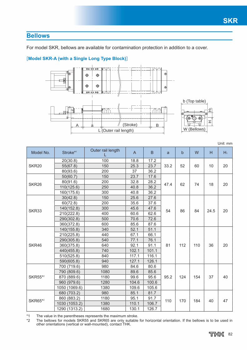
82
SKR
Bellows
For model SKR, bellows are available for contamination protection in addition to a cover.
[Model SKR-A (with a Single Long Type Block)]
(Stroke)
L (Outer rail length) W (Bellows)
b (Top table)
A a B
HH
1
Unit: mm
Model No. Stroke*1 Outer rail lengthL A B a b W H H1
SKR2020(30.8) 100 18.8 17.2
33.2 52 60 10 2055(67.8) 150 25.3 23.780(93.6) 200 37 36.2
SKR26
50(60.7) 150 23.7 17.6
47.4 62 74 18 2080(91.6) 200 32.8 28.2110(125.6) 250 40.8 36.2160(175.6) 300 40.8 36.2
SKR33
30(42.8) 150 25.6 27.6
54 86 84 24.5 20
60(72.8) 200 35.6 37.6140(152.8) 300 45.6 47.6210(222.8) 400 60.6 62.6290(302.8) 500 70.6 72.6360(372.8) 600 85.6 87.6
SKR46
140(155.8) 340 52.1 51.1
81 112 110 36 20
210(225.8) 440 67.1 66.1290(305.8) 540 77.1 76.1360(375.8) 640 92.1 91.1440(455.8) 740 102.1 101.1510(525.8) 840 117.1 116.1590(605.8) 940 127.1 126.1
SKR55*2
700 (719.6) 980 84.6 80.6
95.2 124 154 37 40790 (809.6) 1080 89.6 85.6870 (889.6) 1180 99.6 95.6960 (979.6) 1280 104.6 100.6
1050 (1069.6) 1380 109.6 105.6
SKR65*2
680 (703.2) 980 85.1 81.7
110 170 184 40 47860 (883.2) 1180 95.1 91.71030 (1053.2) 1380 110.1 106.71290 (1313.2) 1680 130.1 126.7
*1 The value in the parentheses represents the maximum stroke.*2 The bellows for models SKR55 and SKR65 are only suitable for horizontal orientation. If the bellows is to be used in
other orientations (vertical or wall-mounted), contact THK.

83
[Model SKR-B (with Two Long Type Blocks)]
L (Outer rail length)
W (Bellows)
b (Top table)
(Stroke)A (a) B
HH
1
Unit: mm
Model No. Stroke*1,*2 Outer rail lengthL A B a b W H H1
SKR20 25(34.8) 150 18.8 17.2 79.2 52 60 10 2060(71.8) 200 25.3 23.7
SKR2635(46.5) 200 23.7 17.6
111.6 62 74 18 2065(77.4) 250 32.8 28.2115(127.4) 300 32.8 28.2
SKR33
80(96.8) 300 35.6 37.6
130 86 84 24.5 20150(166.8) 400 50.6 52.6230(246.8) 500 60.6 62.6300(316.8) 600 75.6 77.6
SKR46
60(75.8) 340 37.1 36.1
191 112 110 36 20
130(145.8) 440 52.1 51.1210(225.8) 540 62.1 61.1280(295.8) 640 77.1 76.1360(375.8) 740 87.1 86.1430(445.8) 840 102.1 101.1510(525.8) 940 112.1 111.1
SKR55*3
590 (612) 980 74.6 70.6
222.8 124 154 37 40670 (692) 1080 84.6 80.6760 (782) 1180 89.6 85.6850 (872) 1280 94.6 90.6930 (952) 1380 104.6 100.6
SKR65*3
550 (578.6) 980 75.1 71.7
254.6 170 184 40 47720 (748.6) 1180 90.1 86.7900 (928.6) 1380 100.1 96.7
1160 (1188.6) 1680 120.1 116.7
*1 The strokes in the table are values when the blocks are in close contact with each other.*2 The value in the parentheses represents the maximum stroke.*3 The bellows for models SKR55 and SKR65 are only suitable for horizontal orientation. If the bellows is to be used in other
orientations (vertical or wall-mounted), contact THK.Note) The bellows cannot be attached between the top tables.
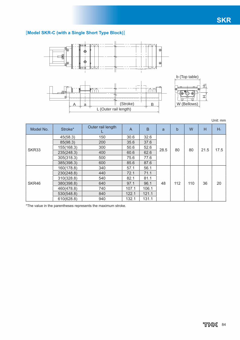
84
SKR[Model SKR-C (with a Single Short Type Block)]
L (Outer rail length)
W (Bellows)
b (Top table)
(Stroke)A Ba
HH
1
Unit: mm
Model No. Stroke* Outer rail lengthL A B a b W H H1
SKR33
45(58.3) 150 30.6 32.6
28.5 80 80 21.5 17.5
85(98.3) 200 35.6 37.6155(168.3) 300 50.6 52.6235(248.3) 400 60.6 62.6305(318.3) 500 75.6 77.6385(398.3) 600 85.6 87.6
SKR46
160(178.8) 340 57.1 56.1
48 112 110 36 20
230(248.8) 440 72.1 71.1310(328.8) 540 82.1 81.1380(398.8) 640 97.1 96.1460(478.8) 740 107.1 106.1530(548.8) 840 122.1 121.1610(628.8) 940 132.1 131.1
*The value in the parentheses represents the maximum stroke.
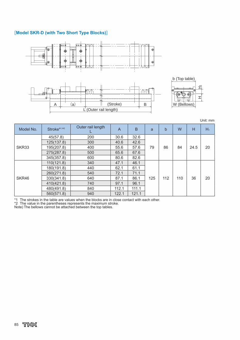
85
[Model SKR-D (with Two Short Type Blocks)]
L (Outer rail length)
W (Bellows)
b (Top table)
(Stroke)A (a) B
HH
1
Unit: mm
Model No. Stroke*1,*2 Outer rail lengthL A B a b W H H1
SKR33
45(57.8) 200 30.6 32.6
79 86 84 24.5 20125(137.8) 300 40.6 42.6195(207.8) 400 55.6 57.6275(287.8) 500 65.6 67.6345(357.8) 600 80.6 82.6
SKR46
110(121.8) 340 47.1 46.1
125 112 110 36 20
180(191.8) 440 62.1 61.1260(271.8) 540 72.1 71.1330(341.8) 640 87.1 86.1410(421.8) 740 97.1 96.1480(491.8) 840 112.1 111.1560(571.8) 940 122.1 121.1
*1 The strokes in the table are values when the blocks are in close contact with each other.*2 The value in the parentheses represents the maximum stroke.Note) The bellows cannot be attached between the top tables.

86
SKR
Precautions on Use[Handling](1) Do not disassemble the parts. This will result in loss of functionality.(2) Take care not to drop or strike the parts. Doing so may cause injury or damage. Giving an impact
to it could also cause damage to its function even if the product looks intact.(3) When handling the product, wear protective gloves, safety shoes, etc., as necessary to ensure
safety.
[Precautions on Use](1) Prevent foreign material, such as cutting chips or coolant, from entering the system. Failure to
do so may cause damage.(2) If the product is used in an environment where cutting chips, coolant, corrosive solvents, water,
etc., may enter the product, use bellows, covers, etc., to prevent them from entering the product.(3) If foreign material such as cutting chips adheres to the product, replenish the lubricant after
cleaning the product.(4) The service temperature range of this product is 0 to 40℃ (no freezing or condensation). If you
consider using this product outside the service temperature range, contact THK.(5) Exceeding the dangerous speed may lead the components to be damaged or cause an accident.
Be sure to use the product within the specifi cation range designated by THK.(6) Micro-strokes tend to obstruct oil fi lm to form on the raceway in contact with the rolling element,
and may lead to fretting corrosion. Take consideration using grease offering excellent fretting prevention. It is also recommended that a stroke movement corresponding to the length of the nut block be made on a regular basis to make sure oil fi lm is formed between the raceway and rolling element.
(7) Do not use undue force when fi tting parts (pin, key, etc.) to the product. This may generate per-manent deformation on the raceway, leading to loss of functionality.
(8) If the product is operating or in the ready state, never touch a moving part. In addition, do not enter the operating area of the actuator.
(9) If two or more people are involved in the operation, confi rm the procedures such as a sequence, signs and anomalies in advance, and appoint another person for monitoring the operation.
(10) Insuffi cient rigidity or accuracy of mounting members causes the bearing load to concentrate on one point and the bearing performance will drop signifi cantly. Accordingly, give suffi cient consid-eration to the rigidity/accuracy of the housing and base and strength of the fi xing bolts.

87
[Lubrication](1) Thoroughly wipe off the anti-rust oil before using the product.(2) Lubrication is needed to let the model SKR demonstrate their functions fully. Using the product
without suffi cient lubrication may increase wear of the rolling elements or shorten the service life. Note the standard grease used in the product as follows.
Models SKR20, SKR26 THK AFA Grease
Models SKR33, SKR46, SKR55, SKR65 THK AFB-LF Grease
(3) Do not mix different lubricants. Mixing greases using the same type of thickening agent may still cause adverse interaction between the two greases if they use different additives, etc.
(4) When using the product in locations exposed to constant vibrations or in special environments such as clean rooms, vacuum and low/high temperature, use the grease appropriate for the specifi cation/environment.
(5) When adopting oil lubrication method, contact THK.(6) Because the intervals between greasing vary depending on the conditions of product use, it is
recommended that the greasing interval be determined through an initial inspection. Although the lubrication interval may vary according to use conditions and the service environment, lubri-cation should be performed approximately every 100 km in travel distance (three to six months). Set the fi nal lubrication interval/amount based on the actual machine.
(7) The consistency of grease changes according to the temperature. Take note that the slide resis-tance of the model SKR also changes as the consistency of grease changes.
(8) After lubrication, the slide resistance of the model SKR may increase due to the agitation resis-tance of grease. Be sure to perform a break-in to let the grease spread fully, before operating the machine.
(9) Excess grease may scatter immediately after lubrication, so wipe off scattered grease as neces-sary.
(10) The properties of grease deteriorate and its lubrication performance drops over time, so grease must be checked and added properly according to the use frequency of the machine.
[Storage]When storing the model SKR, enclose them in a package designated by THK and store them in a room in a horizontal orientation while avoiding high temperature, low temperature and high humidity.After the product has been in storage for an extended period of time, lubricant inside may have de-teriorated, so add new lubricant before use.
[Disposal]Dispose of the product properly as industrial waste.
[Instruction Manual]You can download the “LM Guide Actuator Model SKR -- Instruction Manual” from the THK technical support website.Technical support website: https://tech.thk.com/

SKR
88
SKR
LIMITED WARRANTY
DISCLAIMER
LIMITED WARRANTY AND LIMITATION OF LIABILITY: THK CO. LTD., FOR ITSELF AND ITS RELATED COMPANIES AND
SUBSIDIARIES (HEREINAFTER DESCRIBED COLLECTIVELY AS “THK” ) WARRANTS THAT ALL THK PRODUCTS SOLD WILL BE
FREE OF DEFECTS IN MATERIALS AND WORKMANSHIP FOR A PERIOD OF TWELVE (12) MONTHS FROM DATE OF DELIVERY.
THE FOREGOING TWELVE (12) MONTH WARRANTY SHALL NOT BE EXTENDED OR CHANGED BY THK FURNISHING ANY
REPLACEMENTS, ADDITIONS, ATTACHMENTS, ACCESSORIES OR REPAIRS TO THE PRODUCT SUBSEQUENT TO THE DATE OF
DELIVERY OR ACCEPTANCE. THE FOREGOING WARRANTY IS THE SOLE AND EXCLUSIVE WARRANTY OF THK REGARDING THE
PRODUCT.
DISCLAIMER OF OTHER WARRANTIES: OTHER THAN THE FOREGOING WARRANTY, THERE ARE NO EXPRESS OR IMPLIED
WARRANTIES OR ANY AFFIRMATIONS OF FACT OR PROMISES BY THK WITH RESPECT TO THE PRODUCT. THK DISCLAIMS ANY
WARRANTIES, EXPRESS, IMPLIED OR STATUTORY, NOT SPECIFICALLY SET FORTH ABOVE. WITHOUT LIMITING THE
GENERALITY OF THE FOREGOING, THK EXPRESSLY DISCLAIMS ANY IMPLIED WARRANTIES OF MERCHANTABILITY, FITNESS
FOR ANY PARTICULAR PURPOSE, INFRINGEMENT OR ANY REPRESENTATIONS OF FACT OR QUALITY NOT EXPRESSLY SET
FORTH HEREIN.
LIMITATION OF LIABILITY AND REMEDIES: THK'S SOLE RESPONSIBILITY AND LIABILITY INCURRED AS A RESULT OF THE SALE
AND/OR USE OF THE PRODUCT, AND THE PURCHASER'S EXCLUSIVE REMEDY AGAINST THK UNDER ANY WARRANTY SHALL
BE LIMITED TO THE REPAIR OR REPLACEMENT, AT THK'S OPTION, OF PRODUCT COMPONENTS NOT CONFORMING TO THE
WARRANTY. THE TOTAL LIABILITY OF THK SHALL IN NO EVENT EXCEED THE AMOUNT ACTUALLY PAID TO THK BY
PURCHASER WITH RESPECT TO THE PRODUCT. THIS LIMITATION OF REMEDY IS INTENDED BY THE PARTIES TO SURVIVE
EVEN IF THE REMEDY IS CLAIMED TO HAVE FAILED OF ITS ESSENTIAL PURPOSE. PURCHASER'S FULL AND COMPLETE
PERFORMANCE OF ALL OBLIGATIONS OF PURCHASER RECITED IN THIS AGREEMENT IS A CONDITION PRECEDENT TO THK'S
WARRANTY OBLIGATIONS AND LIABILITIES HEREIN.
PURCHASER'S DAMAGES AND LIMITATIONS: IN NO EVENT SHALL THK BE LIABLE TO PURCHASER, ITS ASSIGNS OR AGENTS,
FOR ECONOMIC LOSS, INCIDENTAL OR CONSEQUENTIAL DAMAGES, IN CONTRACT OR IN TORT, INCLUDING BUT NOT LIMITED
TO, ANY DAMAGES FOR LOST PROFITS, DOWN-TIME, LOST PRODUCTION, FAILURE TO MEET PURCHASER'S SALES
CONTRACTS, OR DEFECTS IN PURCHASER'S MATERIALS OR WORKMANSHIP ARISING DIRECTLY OR INDIRECTLY FROM THE
USE OF THE PRODUCT.
This Catalog provides basic information relating to THK linear motion and related products. The Catalog, including all information, charts,
formulas, factors, accuracy standards, tolerances and application recommendations contained herein, is only a starting point for the
customer’ s selection of appropriate products, and may not apply in all intended applications. The Catalog is not a substitute for a proper
application analysis conducted by an experienced, knowledgeable design engineer. Product selection should be based upon your specific
application needs and conditions, which will vary greatly depending on many factors. No specific product application should be based solely
on the information contained in this Catalog. All purchases of THK Products are subject to the limited warranty offered by THK Co., Ltd, for
itself and on behalf of its related companies and subsidiaries. Customers should confirm independently that a contemplated application is
safe, appropriate and effective.
"All trademarks used in this Catalog are registered trademarks in the Country of Japan. If there is any question as to the validity of such
trademarks outside of Japan, an inquiry should be made in that particular country."
SKR

Caged Ball LM Guide Actuator Model SKR
Head Office 3-11-6 Nishigotanda, Shinagawa-ku, Tokyo 141-8503 JAPANInternational Sales Department Phone:+81-3-5434-0351 Fax:+81-3-5434-0353
NORTH AMERICATHK America,Inc.
HEADQUARTERSPhone:+1-847-310-1111 Fax:+1-847-310-1271CHICAGO OFFICEPhone:+1-847-310-1111 Fax:+1-847-310-1182NORTH EAST OFFICE Phone:+1-631-244-1565 Fax:+1-631-244-1565ATLANTA OFFICEPhone:+1-770-840-7990 Fax:+1-770-840-7897LOS ANGELES OFFICEPhone:+1-949-955-3145 Fax:+1-949-955-3149SAN FRANCISCO OFFICEPhone:+1-925-455-8948 Fax:+1-925-455-8965DETROIT OFFICEPhone:+1-248-858-9330 Fax:+1-248-858-9455TORONTO OFFICEPhone:+1-905-820-7800 Fax:+1-905-820-7811
SOUTH AMERICATHK BRAZIL INDUSTRIA E COMERCIO LTDA.
Phone:+55-11-3767-0100 Fax:+55-11-3767-0101EUROPETHK GmbH
DÜSSELDORF OFFICEPhone:+49-2102-7425-0 Fax:+49-2102-7425-299
EUROPEAN HEADQUARTERSPhone:+49-2102-7425-555 Fax:+49-2102-7425-556
TURKEY OFFICEPhone:+90-216-362-4050 Fax:+90-216-569-7150
MOSCOW OFFICEPhone:+7-495-649-80-47 Fax:+7-495-649-80-44
U.K. OFFICEPhone:+44-1384-47-1550 Fax:+44-1384-47-1551
ITALY OFFICEPhone:+39-02-9901-1801 Fax:+39-02-9901-1881SWEDEN OFFICEPhone:+46-8-445-7630 Fax:+46-8-445-7639 AUSTRIA OFFICEPhone:+43-7229-51400 Fax:+43-7229-51400-79SPAIN OFFICEPhone:+34-93-652-5740 Fax:+34-93-652-5746
EINDHOVEN OFFICETHK Europe B.V.
THK France S.A.S.Phone:+31-040-290-9500 Fax:+31-040-290-9599
PARIS OFFICEPhone:+33-1-7425-3800 Fax:+33-1-7425-3799
Global site : http://www.thk.com/
©THK CO., LTD. 201501000 E24 Printed in Japan
PRAGUE OFFICEPhone:+420-2-41025-100 Fax:+420-2-41025-199
STUTTGART OFFICEPhone:+49-7141-4988-500 Fax:+49-7141-4988-888
SHANGHAI OFFICEPhone:+86-21-6219-3000 Fax:+86-21-6219-9890BEIJING OFFICEPhone:+86-10-8441-7277 Fax:+86-10-6590-3557CHENGDU OFFICEPhone:+86-28-8526-8025 Fax:+86-28-8525-6357GUANGZHOU OFFICEPhone:+86-20-8523-8418 Fax:+86-20-3801-0456
CHINATHK (CHINA) CO.,LTD.
HEADQUARTERSPhone:+86-411-8733-7111 Fax:+86-411-8733-7000
TAIWANTHK TAIWAN CO.,LTD.
TAIPEI HEAD OFFICEPhone:+886-2-2888-3818TAICHUNG OFFICEPhone:+886-4-2359-1505 TAINAN OFFICEPhone:+886-6-289-7668
KOREASEOUL REPRESENTATIVE OFFICE
Phone:+82-2-3468-4351SINGAPORETHK LM System Pte. Ltd.
SHENZHEN OFFICEPhone:+86-755-2642-9587 Fax:+86-755-2642-9604
THK (SHANGHAI) CO.,LTD.Phone:+86-21-6275-5280 Fax:+86-21-6219-9890
Fax:+886-2-2888-3819
Fax:+886-4-2359-1506
THK India Pvt. Ltd.HEADQUARTERS & Bangalore BranchPhone:+91-80-2340-9934Pune BranchPhone:+91-20-4120-8742
Fax:+91-80-2340-9937
Fax:+886-6-289-7669
Fax:+82-2-3468-4353
Fax:+65-6884-5550
INDIA
Phone:+65-6884-5500THAILANDTHK RHYTHM(THAILAND) CO., LTD. LM System Division
Bangkok BranchPhone:+66-2751-3001 Fax:+66-2751-3003
XIAN OFFICEPhone:+86-29-8834-1712 Fax:+86-29-8834-1710
●The photo may differ slightly in appearance from the actual product.●The appearance and specifications of the product are subject to change without notice. Contact THK before placing an order.●Although great care has been taken in the production of this catalog, THK will not take any responsibility for damage resulting from typographical errors or omissions.●For the export of our products or technologies and for the sale for exports, THK in principle complies with the foreign exchange law and the Foreign Exchange
and Foreign Trade Control Law as well as other relevant laws.For export of THK products as single items, contact THK in advance. All rights reserved
“LM GUIDE” and “®
” are registered trademarks of THK CO., LTD.


![NEW Clean-Room Actuator CSKR - THK...Clean-Room Actuator Low dust generation structure High speed (maximum speed 2000[mm/s]) Compact size and high rigidity CATALOG No.355-2E CSKR For](https://static.fdocuments.in/doc/165x107/5e99964c84e8f2199c00d8d5/new-clean-room-actuator-cskr-thk-clean-room-actuator-low-dust-generation-structure.jpg)