Precision, Caged Ball Screw - THK Technical Support · A Precision, Caged Ball Screw Models SBN,...
22
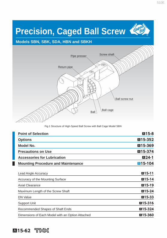
A15-62 Precision, Caged Ball Screw Models SBN, SBK, SDA, HBN and SBKH Screw shaft Pipe presser Return pipe Ball Ball cage Ball screw nut Fig.1 Structure of High-Speed Ball Screw with Ball Cage Model SBN Point of Selection A15-8 Options A15-352 Model No. A15-369 Precautions on Use A15-374 Accessories for Lubrication A24-1 Mounting Procedure and Maintenance B15-104 Lead Angle Accuracy A15-11 Accuracy of the Mounting Surface A15-14 Axial Clearance A15-19 Maximum Length of the Screw Shaft A15-24 DN Value A15-33 Support Unit A15-316 Recommended Shapes of Shaft Ends A15-324 Dimensions of Each Model with an Option Attached A15-360 510E
-
Upload
duongthien -
Category
Documents
-
view
223 -
download
0
Transcript of Precision, Caged Ball Screw - THK Technical Support · A Precision, Caged Ball Screw Models SBN,...
A15-62
Precision, Caged Ball Screw Models SBN, SBK, SDA, HBN and SBKH
Screw shaft Pipe presser
Return pipe
Ball Ball cage
Ball screw nut
Fig.1 Structure of High-Speed Ball Screw with Ball Cage Model SBN
Point of Selection A15-8 Options A15-352 Model No. A15-369 Precautions on Use A15-374 Accessories for Lubrication A24-1 Mounting Procedure and Maintenance B15-104
Lead Angle Accuracy A15-11
Accuracy of the Mounting Surface A15-14
Axial Clearance A15-19
Maximum Length of the Screw Shaft A15-24
DN Value A15-33
Support Unit A15-316
Recommended Shapes of Shaft Ends A15-324
Dimensions of Each Model with an Option Attached A15-360
510E
A15-63
Ball Screw
Precision, Caged Ball Screw
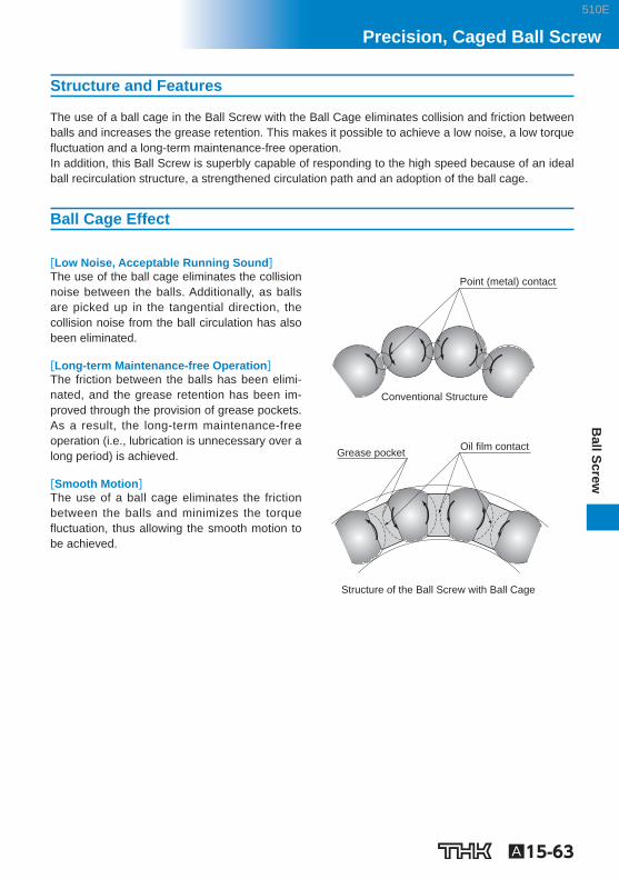
Structure and Features
The use of a ball cage in the Ball Screw with the Ball Cage eliminates collision and friction between balls and increases the grease retention. This makes it possible to achieve a low noise, a low torque fl uctuation and a long-term maintenance-free operation. In addition, this Ball Screw is superbly capable of responding to the high speed because of an ideal ball recirculation structure, a strengthened circulation path and an adoption of the ball cage.
Ball Cage Effect
[Low Noise, Acceptable Running Sound] The use of the ball cage eliminates the collision noise between the balls. Additionally, as balls are picked up in the tangential direction, the collision noise from the ball circulation has also been eliminated.
[Long-term Maintenance-free Operation] The friction between the balls has been elimi-nated, and the grease retention has been im-proved through the provision of grease pockets. As a result, the long-term maintenance-free operation (i.e., lubrication is unnecessary over a long period) is achieved.
[Smooth Motion] The use of a ball cage eliminates the friction between the balls and minimizes the torque fl uctuation, thus allowing the smooth motion to be achieved.
Structure of the Ball Screw with Ball Cage
Oil film contact Grease pocket
Point (metal) contact
Conventional Structure
510E
A15-64
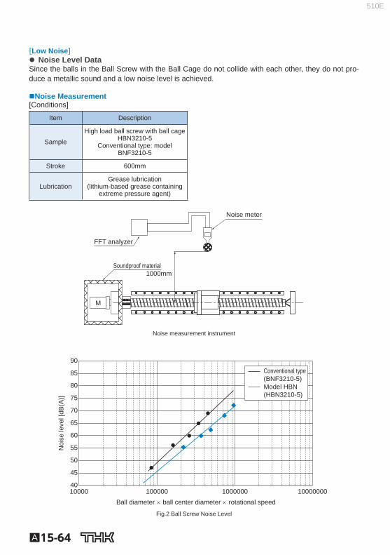
[Low Noise] Noise Level Data
Since the balls in the Ball Screw with the Ball Cage do not collide with each other, they do not pro-duce a metallic sound and a low noise level is achieved.
Noise Measurement [Conditions]
Item Description
Sample High load ball screw with ball cage
HBN3210-5 Conventional type: model
BNF3210-5
Stroke 600mm
Lubrication Grease lubrication
(lithium-based grease containing extreme pressure agent)
Noise meter
Soundproof material
FFT analyzer
1000mm
M
Noise measurement instrument
Ball diameter × ball center diameter × rotational speed
Noi
se le
vel [
dB(A
)]
Conventional type (BNF3210-5) Model HBN (HBN3210-5)
90
85
80
75
70
65
60
55
50
45
40 10000 100000 1000000 10000000
Fig.2 Ball Screw Noise Level
510E
A15-65
Ball Screw
Precision, Caged Ball Screw
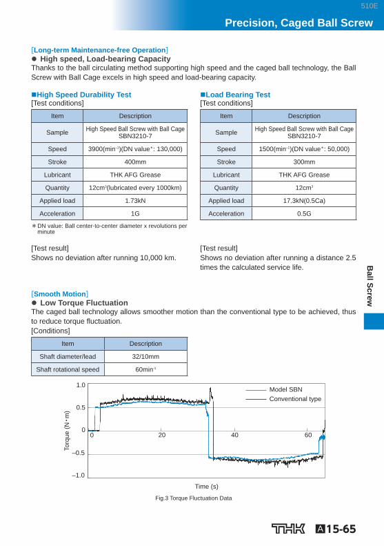
[Long-term Maintenance-free Operation] High speed, Load-bearing Capacity
Thanks to the ball circulating method supporting high speed and the caged ball technology, the Ball Screw with Ball Cage excels in high speed and load-bearing capacity.
High Speed Durability Test [Test conditions]
Item Description
Sample High Speed Ball Screw with Ball Cage SBN3210-7
Speed 3900(min –1 )(DN value * : 130,000)
Stroke 400mm
Lubricant THK AFG Grease
Quantity 12cm 3 (lubricated every 1000km)
Applied load 1.73kN
Acceleration 1G
* DN value: Ball center-to-center diameter x revolutions per minute
Load Bearing Test [Test conditions]
Item Description
Sample High Speed Ball Screw with Ball Cage SBN3210-7
Speed 1500(min –1 )(DN value * : 50,000)
Stroke 300mm
Lubricant THK AFG Grease
Quantity 12cm 3
Applied load 17.3kN(0.5Ca)
Acceleration 0.5G
[Test result] Shows no deviation after running 10,000 km.
[Test result] Shows no deviation after running a distance 2.5 times the calculated service life.
[Smooth Motion] Low Torque Fluctuation
The caged ball technology allows smoother motion than the conventional type to be achieved, thus to reduce torque fl uctuation. [Conditions]
Item Description
Shaft diameter/lead 32/10mm
Shaft rotational speed 60min -1
Time (s)
Torq
ue (N
•m)
Model SBN Conventional type
–1.0
–0.5
0
0.5
1.0
0 20 40 60
Fig.3 Torque Fluctuation Data
510E
A15-66
Types and Features
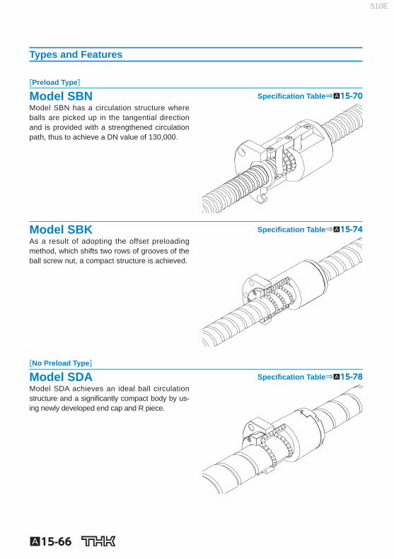
[Preload Type]
Model SBN Specifi cation Table⇒A15-70 Model SBN has a circulation structure where balls are picked up in the tangential direction and is provided with a strengthened circulation path, thus to achieve a DN value of 130,000.
Model SBK Specifi cation Table⇒A15-74 As a result of adopting the offset preloading method, which shifts two rows of grooves of the ball screw nut, a compact structure is achieved.
[No Preload Type]
Model SDA Specifi cation Table⇒A15-78 Model SDA achieves an ideal ball circulation structure and a signifi cantly compact body by us-ing newly developed end cap and R piece.
510E
A15-67
Ball Screw
Precision, Caged Ball Screw
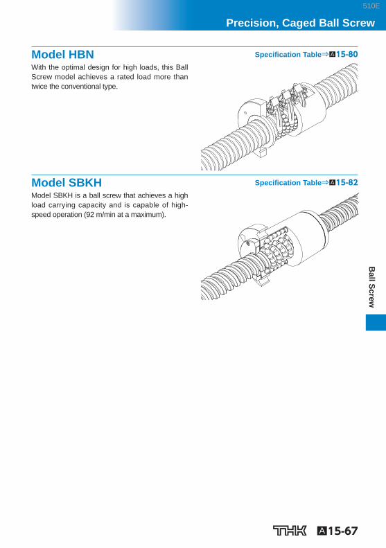
Model HBN Specifi cation Table⇒A15-80 With the optimal design for high loads, this Ball Screw model achieves a rated load more than twice the conventional type.
Model SBKH Specifi cation Table⇒A15-82 Model SBKH is a ball screw that achieves a high load carrying capacity and is capable of high-speed operation (92 m/min at a maximum).
510E
A15-68
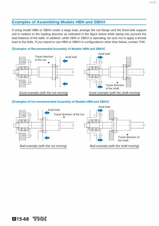
Examples of Assembling Models HBN and SBKH
If using model HBN or SBKH under a large load, arrange the nut fl ange and the fi xed-side support unit in relation to the loading direction as indicated in the fi gure below while taking into account the load balance of the balls. In addition, while HBN or SBKH is operating, be sure not to apply a tensile load to the bolts. If you intend to use HBN or SBKH in confi gurations other than below, contact THK.
[Examples of Recommended Assembly of Models HBN and SBKH]
Good example (with the nut moving)
Axial loadTravel directionof the nut
Axial load
Good example (with the shaft moving)
Travel directionof the shaft
[Examples of Un-recommended Assembly of Models HBN and SBKH]
Axial loadAxial load
Bad example (with the nut moving) Bad example (with the shaft moving)
Travel direction of the nut
Travel direction of the shaft
510E
A15-69
Ball Screw
Precision, Caged Ball Screw510E
Model number coding
A15-70 To download a desired data, search for the corresponding model number in the Technical site. https://tech.thk.com
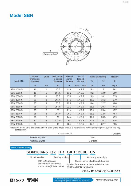
Model SBN
(Greasing hole)
PCD
A
60°
Model No.
Screw shaft outerdiameter
Lead Ball center-to-centerdiameter
Threadminor
diameter
No. ofloaded circuits
Basic load rating Rigidity
Ca C 0 a K
d Ph dp dc Rows × turns kN kN N/m
SBN 1604-5 16 4 16.5 13.8 1×2.5 5.3 8 281 SBN 1605-5 16 5 16.75 13.2 1×2.5 9.2 12.9 309 SBN 2004-5 20 4 20.5 17.8 1×2.5 5.9 10.1 335 SBN 2005-5 20 5 20.75 17.2 1×2.5 10.3 16.2 370 SBN 2504-5 25 4 25.5 22.8 1×2.5 6.4 12.7 400 SBN 2505-5 25 5 25.75 22.2 1×2.5 11.3 20.3 442 SBN 2506-5 25 6 26 21.4 1×2.5 15.4 25.4 457 SBN 2805-5 28 5 28.75 25.2 1×2.5 11.8 22.8 483 SBN 2806-5 28 6 29 24.4 1×2.5 16.2 28.5 499 SBN 3205-5 32 5 32.75 29.2 1×2.5 12.6 26.1 536 SBN 3206-5 32 6 33 28.4 1×2.5 17.2 32.7 555
Note) With model SBN, the raising of both ends of the thread groove is not available. When designing your system this way, contact THK.
Axial Clearance Unit: mm
Clearance symbol G0 Axial Clearance 0 or less
Seal symbol (*1)
With QZ Lubricator (no symbol if the model is without a QZ Lubricator)
Accuracy symbol (*2)
Overall screw shaft length (in mm)Symbol for Clearance in the axial direction (G0 for all SBN variations)
Model Number
SBN1604-5 QZ RR G0 +1200L C5
(*1) See A15-352 . (*2) See A15-12 .
510E

A15-71
Ball Screw
Precision, Caged Ball Screw
Options⇒A15-351
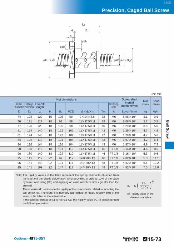
L1
B1 H
h
φ d2
φ dφ D1
φ d1
φ dc φDg6
Unit: mm
Nut dimensions Screw shaftinertial
moment/mm Nut
mass Shaft mass Outer
diameter Flange
diameter Overall length Greasing
hole Dg 6 D 1 L 1 H B 1 PCD d 1 ×d 2 ×h A kg•cm 2 /mm kg kg/m
36 59 53 11 42 47 5.5×9.5×5.5 M6×1 5.05×10 -4 0.42 1.35 40 60 56 10 46 50 4.5×8×4.5 M6×1 5.05×10 -4 0.50 1.25 40 63 53 11 42 51 5.5×9.5×5.5 M6×1 1.23×10 -3 0.48 2.18 44 67 56 11 45 55 5.5×9.5×5.5 M6×1 1.23×10 -3 0.61 2.06 46 69 48 11 37 57 5.5×9.5×5.5 M6×1 3.01×10 -3 0.55 3.50 50 73 55 11 44 61 5.5×9.5×5.5 M6×1 3.01×10 -3 0.72 3.35 53 76 62 11 51 64 5.5×9.5×5.5 M6×1 3.01×10 -3 0.90 3.19 55 85 59 12 47 69 6.6×11×6.5 M6×1 4.74×10 -3 0.98 4.27 59 89 63 12 51 73 6.6×11×6.5 M6×1 4.74×10 -3 1.19 4.33 58 85 56 12 44 71 6.6×11×6.5 M6×1 8.08×10 -3 0.96 5.67 62 89 63 12 51 75 6.6×11×6.5 M6×1 8.08×10 -3 1.22 6.31
Note) The rigidity values in the table represent the spring constants obtained from the load and the elastic deformation when providing a preload 10% of the basic dynamic load rating (Ca) and applying an axial load three times greater than the preload. These values do not include the rigidity of the components related to mounting the ball screw nut. Therefore, it is normally appropriate to regard roughly 80% of the value in the table as the actual value. If the applied preload (Fa 0 ) is not 0.1 Ca, the rigidity value (K N ) is obtained from the following equation.
K: Rigidity value in the dimensional table.
1 3 Fa0
0.1Ca KN=K ( )
510E
Model number coding
A15-72 To download a desired data, search for the corresponding model number in the Technical site. https://tech.thk.com
Model SBN
Plug
(Greasing hole)
30°
A Tm
30° 30°
PCD
Model No.
Screw shaft outerdiameter
Lead Ball center-to-centerdiameter
Threadminor
diameter
No. ofloadedcircuits
Basic load rating Rigidity
Ca C 0 a K
d Ph dp dc Rows × turns kN kN N/m
○ SBN 3210-7 32 10 33.75 26.4 1×3.5 43 73.1 836.7 ○ SBN 3212-5 32 12 34 26.1 1×2.5 37.4 58.7 612.2 ○ SBN 3610-7 36 10 37.75 30.4 1×3.5 45.6 82.3 920.9 ○ SBN 3612-7 36 12 38 30.1 1×3.5 53.2 92.6 934.5 ○ SBN 3616-5 36 16 38 30.1 1×2.5 39.7 66.4 676 ○ SBN 4012-5 40 12 42 34.1 1×2.5 42 73.6 735.4 ○ SBN 4016-5 40 16 42 34.1 1×2.5 41.9 73.8 736.6 ○ SBN 4512-5 45 12 47 39.2 1×2.5 44.4 82.9 809.1 ○ SBN 4516-5 45 16 47 39.2 1×2.5 44.3 83.1 810.1 ○ SBN 5012-5 50 12 52 44.1 1×2.5 46.6 92.2 880.9 ○ SBN 5016-5 50 16 52 44.1 1×2.5 46.6 92.4 881.7 ○ SBN 5020-5 50 20 52 44.1 1×2.5 46.5 92.6 882.8 Note) With model SBN, the raising of both ends of the thread groove is not available. When designing your system this way,
contact THK. Those models marked with ○ can be attached with QZ Lubricator or the wiper ring. For dimensions of the ball screw nut with either accessory being attached, see A15-360 .
Axial Clearance Unit: mm
Clearance symbol G0 Axial Clearance 0 or less
Seal symbol (*1)
Accuracy symbol (*2)
Overall screw shaft length (in mm)
Symbol for Clearance in the axial direction(G0 for all SBN variations)
Model number
SBN4012-5 RR G0 +1400L C5
(*1) See A15-352 . (*2) See A15-12 .
510E
A15-73
Ball Screw
Precision, Caged Ball Screw
Options⇒A15-351
L1
H
φ d1
φ d2
h
B1
φ dpφ D1 φ dc φ d φ Dg6
Unit: mm
Nut dimensions Screw shaft inertial
moment/mm Nut
mass Shaftmass Outer
diameter Flange
diameter Overall length Greasing
hole D D 1 L 1 H B 1 PCD d 1 ×d 2 ×h Tm A kg•cm 2 /mm kg kg/m
74 108 120 15 105 90 9×14×8.5 38 M6 8.08×10 -3 3.1 3.6 76 121 117 18 99 98 11×17.5×11 39 M6 8.08×10 -3 3.7 3.5 77 120 123 18 105 98 11×17.5×11 40 M6 1.29×10 -2 3.8 5.0 81 124 140 18 122 102 11×17.5×11 42 M6 1.29×10 -2 4.7 4.8 81 124 140 18 122 102 11×17.5×11 42 M6 1.29×10 -2 4.7 5.6 84 126 119 18 101 104 11×17.5×11 43 M6 1.97×10 -2 4.2 6.4 84 126 144 18 126 104 11×17.5×11 43 M6 1.97×10 -2 4.9 7.3 90 130 119 18 101 110 11×17.5×11 46 PT 1/8 3.16×10 -2 4.6 8.6 90 130 140 18 122 110 11×17.5×11 46 PT 1/8 3.16×10 -2 5.3 9.6 95 141 119 22 97 117 14×20×13 48 PT 1/8 4.82×10 -2 5.3 11.1 95 141 143 22 121 117 14×20×13 48 PT 1/8 4.82×10 -2 6.1 12.2 95 141 169 22 147 117 14×20×13 48 PT 1/8 4.82×10 -2 7.0 12.8
Note) The rigidity values in the table represent the spring constants obtained from the load and the elastic deformation when providing a preload 10% of the basic dynamic load rating (Ca) and applying an axial load three times greater than the preload. These values do not include the rigidity of the components related to mounting the ball screw nut. Therefore, it is normally appropriate to regard roughly 80% of the value in the table as the actual value. If the applied preload (Fa 0 ) is not 0.1 Ca, the rigidity value (K N ) is obtained from the following equation.
K: Rigidity value in the dimensional table.
1 3 Fa0
0.1Ca KN=K ( )
510E
Model number coding
A15-74 To download a desired data, search for the corresponding model number in the Technical site. https://tech.thk.com
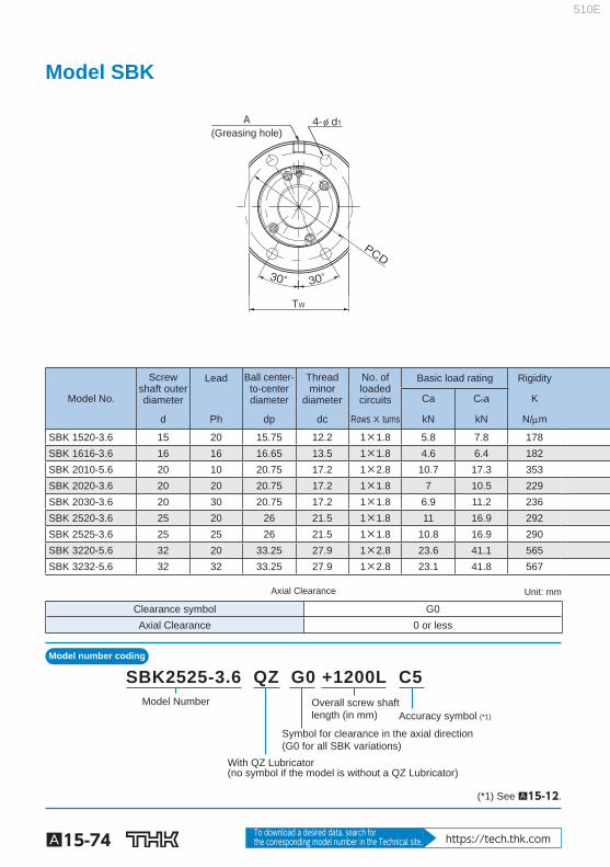
Model SBK
(Greasing hole)
TW
30° 30°
PCD
A 4-φ d1
Model No.
Screw shaft outerdiameter
Lead Ball center-to-centerdiameter
Threadminor
diameter
No. ofloadedcircuits
Basic load rating Rigidity
Ca C 0 a K
d Ph dp dc Rows × turns kN kN N/m
SBK 1520-3.6 15 20 15.75 12.2 1×1.8 5.8 7.8 178 SBK 1616-3.6 16 16 16.65 13.5 1×1.8 4.6 6.4 182 SBK 2010-5.6 20 10 20.75 17.2 1×2.8 10.7 17.3 353 SBK 2020-3.6 20 20 20.75 17.2 1×1.8 7 10.5 229 SBK 2030-3.6 20 30 20.75 17.2 1×1.8 6.9 11.2 236 SBK 2520-3.6 25 20 26 21.5 1×1.8 11 16.9 292 SBK 2525-3.6 25 25 26 21.5 1×1.8 10.8 16.9 290 SBK 3220-5.6 32 20 33.25 27.9 1×2.8 23.6 41.1 565 SBK 3232-5.6 32 32 33.25 27.9 1×2.8 23.1 41.8 567
Axial Clearance Unit: mm
Clearance symbol G0 Axial Clearance 0 or less
With QZ Lubricator(no symbol if the model is without a QZ Lubricator)
Accuracy symbol (*1)
Overall screw shaftlength (in mm)
Symbol for clearance in the axial direction(G0 for all SBK variations)
Model Number
SBK2525-3.6 QZ G0 +1200L C5
(*1) See A15-12 .
510E
A15-75
Ball Screw
Precision, Caged Ball Screw
Options⇒A15-351
φ Dg6φ dc φ dφ D1 φ D
HL1
B1
Unit: mm
Nut dimensions Screw shaft inertialmoment/mm
Nut mass
Shaft mass
Maximum permissible
rotation speed Outerdiameter
Flangediameter
Overall length Greasing
hole D D 1 L 1 H B 1 PCD d 1 T W A kg•cm 2 /mm kg kg/m min -1
38 62 54 10 38.5 49 5.5 39 M6 3.9×10 -4 0.41 1.27
5000
33 54 45 10 29.5 43 4.5 38 M6 5.05×10 -4 0.25 1.46 40 65 45 10 29.5 53 5.5 49 M6 1.23×10 -3 0.37 2.18 40 65 54 10 38.5 53 5.5 49 M6 1.23×10 -3 0.43 2.32 40 65 71 10 55.5 53 5.5 49 M6 1.23×10 -3 0.55 2.36 47 74 57 12 38 60 6.6 56 M6 3.01×10 -3 0.59 3.58 47 74 68 12 49 60 6.6 56 M6 3.01×10 -3 0.69 3.63 58 92 82 15 58 74 9 68 M6 8.08×10 -3 1.23 5.82
3900 58 92 118 15 94 74 9 68 M6 8.08×10 -3 1.70 5.99
Note) The rigidity values in the table represent the spring constants obtained from the load and the elastic deformation when providing a preload 10% of the basic dynamic load rating (Ca) and applying an axial load three times greater than the preload. These values do not include the rigidity of the components related to mounting the ball screw nut. Therefore, it is normally appropriate to regard roughly 80% of the value in the table as the actual value. If the applied preload (Fa 0 ) is not 0.1 Ca, the rigidity value (K N ) is obtained from the following equation.
K: Rigidity value in the dimensional table.
1 3 Fa0
0.1Ca KN=K ( )
510E

Model number coding
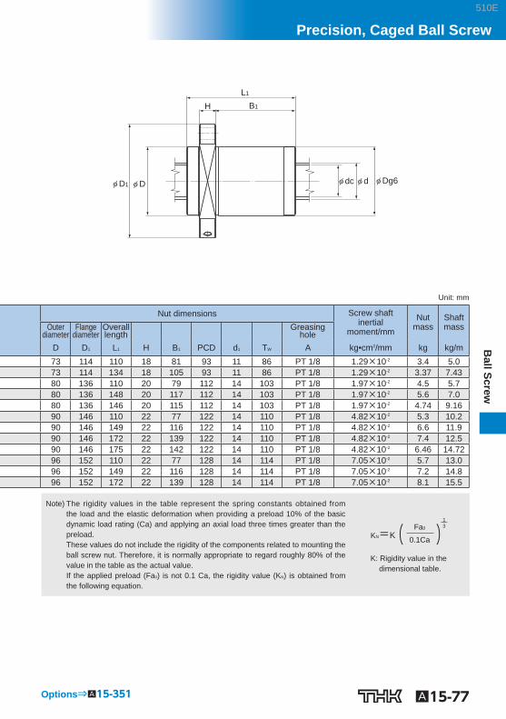
A15-76 To download a desired data, search for the corresponding model number in the Technical site. https://tech.thk.com
Model SBK
(Greasing hole)
6-φ d1
A
PCD
TW
45°45°
22°
Model No.
Screw shaft outerdiameter
Lead Ball center-to-centerdiameter
Threadminor
diameter
No. ofloadedcircuits
Basic load rating Rigidity
Ca C 0 a K
d Ph dp dc Rows × turns kN kN N/m SBK 3620-7.6 36 20 37.75 30.4 1×3.8 48.5 85 870 SBK 3636-5.6 36 36 37.75 31.4 1×2.8 36.6 64.7 460 SBK 4020-7.6 40 20 42 34.1 1×3.8 59.7 112.7 970 SBK 4030-7.6 40 30 42 34.1 1×3.8 59.2 107.5 970 SBK 4040-5.6 40 40 42 34.9 1×2.8 44.8 80.3 520 SBK 5020-7.6 50 20 52 44.1 1×3.8 66.8 141.9 1170 SBK 5030-7.6 50 30 52 44.1 1×3.8 66.5 135 1170 SBK 5036-7.6 50 36 52 44.1 1×3.8 65.9 135 1170 SBK 5050-5.6 50 50 52 44.9 1×2.8 50.3 102.4 630 SBK 5520-7.6 55 20 57 49.1 1×3.8 69.8 156.4 1250 SBK 5530-7.6 55 30 57 49.1 1×3.8 69.2 147 1250 SBK 5536-7.6 55 36 57 49.1 1×3.8 69.1 148.7 1260 Note) With model SBK, the raising of both ends of the thread groove is not available. When designing your system this way,
contact THK.
Axial Clearance Unit: mm
Clearance symbol G0 Axial Clearance 0 or less
Seal symbol (*1)
Accuracy symbol (*2)
Overall screw shaft length (in mm)
Model number
Symbol for clearancein the axial direction (G0 for all SBK variations)
SBK3620-7.6 RR G0 +1500L C5
(*1) See A15-352 . (*2) See A15-12 .
510E
A15-77
Ball Screw
Precision, Caged Ball Screw
Options⇒A15-351
B1
L1
H
φ D1 φ D φ Dg6φ dc φ d
Unit: mm
Nut dimensions Screw shaftinertial
moment/mm
Nutmass
Shaftmass Outer
diameter Flange
diameter Overall length Greasing
hole D D 1 L 1 H B 1 PCD d 1 T W A kg•cm 2 /mm kg kg/m 73 114 110 18 81 93 11 86 PT 1/8 1.29×10 -2 3.4 5.0 73 114 134 18 105 93 11 86 PT 1/8 1.29×10 -2 3.37 7.43 80 136 110 20 79 112 14 103 PT 1/8 1.97×10 -2 4.5 5.7 80 136 148 20 117 112 14 103 PT 1/8 1.97×10 -2 5.6 7.0 80 136 146 20 115 112 14 103 PT 1/8 1.97×10 -2 4.74 9.16 90 146 110 22 77 122 14 110 PT 1/8 4.82×10 -2 5.3 10.2 90 146 149 22 116 122 14 110 PT 1/8 4.82×10 -2 6.6 11.9 90 146 172 22 139 122 14 110 PT 1/8 4.82×10 -2 7.4 12.5 90 146 175 22 142 122 14 110 PT 1/8 4.82×10 -2 6.46 14.72 96 152 110 22 77 128 14 114 PT 1/8 7.05×10 -2 5.7 13.0 96 152 149 22 116 128 14 114 PT 1/8 7.05×10 -2 7.2 14.8 96 152 172 22 139 128 14 114 PT 1/8 7.05×10 -2 8.1 15.5
Note) The rigidity values in the table represent the spring constants obtained from the load and the elastic deformation when providing a preload 10% of the basic dynamic load rating (Ca) and applying an axial load three times greater than the preload. These values do not include the rigidity of the components related to mounting the ball screw nut. Therefore, it is normally appropriate to regard roughly 80% of the value in the table as the actual value. If the applied preload (Fa 0 ) is not 0.1 Ca, the rigidity value (K N ) is obtained from the following equation.
K: Rigidity value in the dimensional table.
1 3 Fa0
0.1Ca KN=K ( )
510E
Model number coding
A15-78 To download a desired data, search for the corresponding model number in the Technical site. https://tech.thk.com
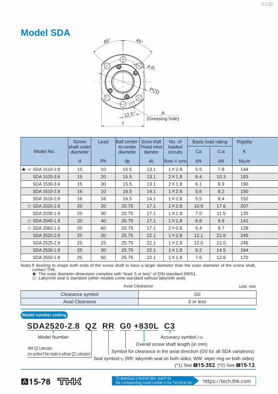
Model SDA
A(Greasing hole)
T
PCD
22.5°
45° 45°
φ d1
Model No.
Screw shaft outerdiameter
Lead Ball center-to-centerdiameter
Screw shaft Thread minor
diameter
No. ofloadedcircuits
Basic load rating Rigidity
Ca C 0 a K
d Ph dp dc Rows × turns kN kN N/m
★ ☆ SDA 1510-2.8 15 10 15.5 13.1 1×2.8 5.5 7.8 144 SDA 1520-3.6 15 20 15.5 13.1 2×1.8 6.4 10.3 183 SDA 1530-3.6 15 30 15.5 13.1 2×1.8 6.1 8.9 190 SDA 1610-2.8 16 10 16.5 14.1 1×2.8 5.6 8.2 150 SDA 1616-2.8 16 16 16.5 14.1 1×2.8 5.5 8.4 152 ☆ SDA 2020-2.8 20 20 20.75 17.1 1×2.8 10.9 17.6 207 SDA 2030-1.8 20 30 20.75 17.1 1×1.8 7.0 11.5 135 ☆ SDA 2040-1.8 20 40 20.75 17.1 1×1.8 6.8 9.9 141 ☆ SDA 2060-1.6 20 60 20.75 17.1 2×0.8 5.4 9.7 128 SDA 2520-2.8 25 20 25.75 22.1 1×2.8 12.1 21.6 245 SDA 2525-2.8 25 25 25.75 22.1 1×2.8 12.0 22.0 246 SDA 2530-1.8 25 30 25.75 22.1 1×1.8 8.2 14.5 164 SDA 2550-1.8 25 50 25.75 22.1 1×1.8 7.6 12.6 170
Note) If desiring to shape both ends of the screw shaft to have a larger diameter than the outer diameter of the screw shaft, contact THK. ★: The outer diameter dimension complies with “lead: 5 or less” of DIN standard 69051. ☆: Labyrinth seal is standard (other models come standard without labyrinth seal).
Axial Clearance Unit: mm
Clearance symbol G0 Axial Clearance 0 or less
Model Number
With QZ Lubricator (no symbol if the model is without QZ Lubricator)
Overall screw shaft length (in mm)Symbol for clearance in the axial direction (G0 for all SDA variations)
Accuracy symbol (*2)
Seal symbol(*1) (RR: labyrinth seal on both sides; WW: wiper ring on both sides)
SDA2520-2.8 QZ RR G0 +830L C3
(*1) See A15-352 . (*2) See A15-12 .
510E
A15-79
Ball Screw
Precision, Caged Ball Screw
Options⇒A15-351
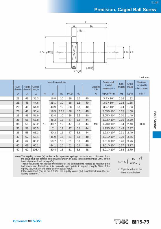
φ D1 φ D
φ D g6
φ dC φ d
L1
HB2
B1
-0.2-0.3
φ D-0.2-0.3
Unit: mm
Nut dimensions Screw shaftinertial
moment/mm Nut
mass Shaft mass
Maximum permissible
rotation speed Outerdiameter
Flangediameter
Overalllength Greasing
hole D D 1 L 1 H B 1 B 2 PCD d 1 T A kg•cm 2 /mm kg kg/m min -1
28 48 35.3
10
16.8 10 38 5.5 40
M6
3.9×10 -4 0.16 1.32
5000
28 48 44.6 25.1 10 38 5.5 40 3.9×10 -4 0.18 1.35 28 48 64.9 43.9 10 38 5.5 40 3.9×10 -4 0.24 1.33 28 48 35.4 16.9 12.9 38 5.5 40 5.05×10 -4 0.15 1.50 28 48 51.9 33.4 10 38 5.5 40 5.05×10 -4 0.20 1.49 36 58 65.8 45.3 12 47 6.6 44 1.23×10 -3 0.35 2.39 36 58 65.2 43.7 12 47 6.6 44 1.23×10 -3 0.34 2.40 36 58 85.5 61 12 47 6.6 44 1.23×10 -3 0.43 2.37 36 58 66.3 40.3 12 47 6.6 44 1.23×10 -3 0.31 2.40 40 62 66.4 45.9 16 51 6.6 48 3.01×10 -3 0.39 3.75 40 62 80.2 59.7 16 51 6.6 48 3.01×10 -3 0.46 3.76 40 62 65.1 44.1 16 51 6.6 48 3.01×10 -3 0.37 3.77 40 62 105.4 80.4 16 51 6.6 48 3.01×10 -3 0.58 3.79
Note) The rigidity values (K) in the table represent spring constants each obtained from the load and the elastic deformation under an axial load representing 30% of the basic dynamic load rating (Ca). These values do not include the rigidity of the components related to mounting the ball screw nut. Therefore, it is normally appropriate to regard roughly 80% of the rigidity value (K) in the table as the actual value. If the axial load (Fa) is not 0.3 Ca, the rigidity value (K N ) is obtained from the fol-lowing equation.
K: Rigidity value in the dimensional table.
13Fa
0.3CaKN=K( )
510E
Model number coding
A15-80 To download a desired data, search for the corresponding model number in the Technical site. https://tech.thk.com
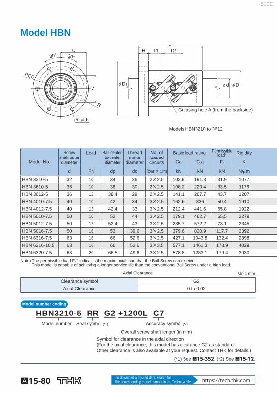
Model HBN
Greasing hole A (from the backside)
Models HBN3210 to 3612
30° 30°
R
PCD
U
V
5–φ d1
φ D1
H T1 T2
φ d φ D
L1
Model No.
Screw shaft outerdiameter
Lead Ball center-to-centerdiameter
Threadminor
diameter
No. ofloadedcircuits
Basic load rating Permissibleload* Rigidity
Ca C 0 a F P K
d Ph dp dc Rows × turns kN kN kN N/m
HBN 3210-5 32 10 34 26 2×2.5 102.9 191.3 31.9 1077 HBN 3610-5 36 10 38 30 2×2.5 108.2 220.4 33.5 1176 HBN 3612-5 36 12 38.4 29 2×2.5 141.1 267.7 43.7 1207 HBN 4010-7.5 40 10 42 34 3×2.5 162.6 336 50.4 1910 HBN 4012-7.5 40 12 42.4 33 3×2.5 212.4 441.6 65.8 1922 HBN 5010-7.5 50 10 52 44 3×2.5 179.1 462.7 55.5 2279 HBN 5012-7.5 50 12 52.4 43 3×2.5 235.7 572.2 73.1 2345 HBN 5016-7.5 50 16 53 39.6 3×2.5 379.6 820.9 117.7 2392 HBN 6316-7.5 63 16 66 52.6 3×2.5 427.1 1043.8 132.4 2898 HBN 6316-10.5 63 16 66 52.6 3×3.5 577.1 1461.3 178.9 4029 HBN 6320-7.5 63 20 66.5 49.6 3×2.5 578.8 1283.1 179.4 3030
Note) The permissible load F P * indicates the maxim axial load that the Ball Screw can receive. This model is capable of achieving a longer service life than the conventional Ball Screw under a high load.
Axial Clearance Unit: mm
Clearance symbol G2 Axial Clearance 0 to 0.02
Model number
Symbol for clearance in the axial direction(For the axial clearance, this model has clearance G2 as standard. Other clearance is also available at your request. Contact THK for details.)
Overall screw shaft length (in mm)
Accuracy symbol (*2)Seal symbol (*1)
HBN3210-5 RR G2 +1200L C7
(*1) See A15-352 . (*2) See A15-12 .
510E

A15-81
Ball Screw
Precision, Caged Ball Screw
Options⇒A15-351
Greasing hole A (from the backside)
Models HBN4010 to 6320
L1H T1 T2 T2
φ D1 φ d φ D
Unit: mm
Nut dimensions Screw shaftinertial
moment/mm
Nutmass
Shaftmass Outer
diameter Flange
diameter Overalllength
Greasinghole
D D 1 L 1 H PCD d 1 T1 T2 U MAX V MAX R MAX A kg•cm 2 /mm kg kg/m
58 85 98 15 71 6.6 22 30 43 46 43.5 M6 8.08×10 -3 1.8 5.26 62 89 98 15 75 6.6 22 30 45 50 46 M6 1.29×10 -2 1.9 6.79 66 100 116 18 82 9 26 36 49 52.5 50 M6 1.29×10 -2 2.8 6.55 66 100 135 18 82 9 23.5 30 46.5 54 48 M6 1.97×10 -2 2.9 8.52 70 104 152 18 86 9 26 36 51 56 52 M6 1.97×10 -2 3.7 5.24 78 112 135 18 94 9 23.5 30 52 63.5 54.5 M6 4.82×10 -2 3.7 13.7 80 114 152 18 96 9 26 36 56 66 58.5 M6 4.82×10 -2 4.4 13.34 95 135 211 28 113 9 37.5 48 64.5 69.6 65.2 PT 1/8 4.82×10 -2 10.0 12.1 105 139 211 28 122 9 37.5 48 70.5 82 72.5 PT 1/8 1.21×10 -1 10.6 20.2 105 139 259 28 122 9 53.5 64 70.5 82 73 PT 1/8 1.21×10 -1 17.4 20.2 117 157 252 32 137 11 44 60 79 86.5 80 PT 1/8 1.21×10 -1 17.2 19.13
Note) The rigidity values in the table represent the spring constants obtained from the load and the elastic deformation when providing an axial load, 30% of the basic dynamic load rating (Ca). These values do not include the rigidity of the components related to mounting the ball screw nut. Therefore, it is normally appropriate to regard roughly 80% of the value in the table as the actual value. If the axial load (Fa) is not 0.3 Ca, the rigidity value (K N ) is obtained from the fol-lowing equation.
K: Rigidity value in the dimensional table.
1 3 Fa
0.3Ca KN=K ( )
510E
Model number coding
A15-82 To download a desired data, search for the corresponding model number in the Technical site. https://tech.thk.com
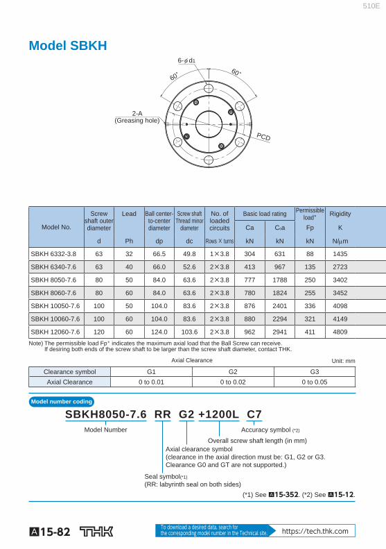
Model SBKH
(Greasing hole)
60°60°
PCD
6-φ d1
2-A
Model No.
Screw shaft outerdiameter
Lead Ball center-to-center diameter
Screw shaft Thread minor
diameter
No. ofloaded circuits
Basic load rating Permissibleload * Rigidity
Ca C 0 a Fp K
d Ph dp dc Rows × turns kN kN kN N/m
SBKH 6332-3.8 63 32 66.5 49.8 1×3.8 304 631 88 1435
SBKH 6340-7.6 63 40 66.0 52.6 2×3.8 413 967 135 2723
SBKH 8050-7.6 80 50 84.0 63.6 2×3.8 777 1788 250 3402
SBKH 8060-7.6 80 60 84.0 63.6 2×3.8 780 1824 255 3452
SBKH 10050-7.6 100 50 104.0 83.6 2×3.8 876 2401 336 4098
SBKH 10060-7.6 100 60 104.0 83.6 2×3.8 880 2294 321 4149
SBKH 12060-7.6 120 60 124.0 103.6 2×3.8 962 2941 411 4809
Note) The permissible load Fp * indicates the maximum axial load that the Ball Screw can receive. If desiring both ends of the screw shaft to be larger than the screw shaft diameter, contact THK.
Axial Clearance Unit: mm
Clearance symbol G1 G2 G3 Axial Clearance 0 to 0.01 0 to 0.02 0 to 0.05
Model Number
Seal symbol(*1) (RR: labyrinth seal on both sides)
Overall screw shaft length (in mm)
Accuracy symbol (*2)
Axial clearance symbol(clearance in the axial direction must be: G1, G2 or G3.Clearance G0 and GT are not supported.)
SBKH8050-7.6 RR G2 +1200L C7
(*1) See A15-352 . (*2) See A15-12 .
510E

A15-83
Ball Screw
Precision, Caged Ball Screw
Options⇒A15-351
H B1
L1
φ D1 φ dc φ d φ Dg6
B2
φ D2
N1
Unit: mm
Nut dimensions Screw shaftinertial
moment/mm Nut
mass Shaft
mass *1 Outerdiameter
Flange diameter
Capdiameter
Overall length Greasing
hole D D 1 D 2 L 1 H B 1 B 2 PCD d 1 N 1 A kg•cm 2 /mm kg kg/m
140 205 (140) 190 28 143 (19) 173 22 14 PT1/8 1.21×10 -1 17.2 21.0
127 191 (127) 209 30 163 (16) 159 22 15 PT1/8 1.21×10 -1 15.5 21.0
175 253 (175) 268 32 213 (23) 214 26 16 PT1/8 3.16×10 -1 36.9 31.3
175 253 (175) 306 40 243 (23) 214 26 20 PT1/8 3.16×10 -1 43.5 32.5
195 273 (195) 269 40 206 (23) 234 26 20 PT1/8 7.71×10 -1 44.5 51.3
195 273 (195) 307 40 244 (23) 234 26 20 PT1/8 7.71×10 -1 50.5 52.9
210 288 (210) 308 45 240 (23) 249 26 22.5 PT1/8 1.60 53.7 78.1
Note1) There will be no dimensional change after the seal is attached. Note2) The rigidity values (K) in the table represent spring constants each obtained
from the load and the elastic deformation under an axial load representing 30% of the basic dynamic load rating (Ca). These values do not include the rigidity of the components related to mounting the ball screw nut. Therefore, it is normally appropriate to regard roughly 80% of the rigidity value (K) in the table as the actual value. If the axial load (Fa) is not 0.3 Ca, the rigidity value (K N ) is obtained from the fol-lowing equation.
K: Rigidity value in the dimensional table.
13Fa
0.3CaKN=K( )
510E