Cadenas Renold Ansi
14
Page 7 B29.1 ANSI STANDARD - SINGLE ANSI STANDARD - SINGLE Chain Connecting Links ANSI Renold Pitch Pitch Inside Roller Plate Plate Plate Pin Pin Con Trans F B Weight No No No No No No No No Chain Inch mm Width Dia Height Width Width Dia Len Link Pitch lbf lb/ft 4 107 11 26 58 12 30 No Inner Outer Extra A A B C D E F G H1 J K 25 129023* 0.250 6.350 0.125 0.130* 0.232 0.030 0.030 0.091 0.339 0.031 - 920 0.09 ✓ ✓ - ✓ - - ✓ 35 129033* 0.375 9.525 0.188 0.200* 0.341 0.050 0.050 0.141 0.610 0.130 - 2300 0.22 ✓ ✓ - ✓ - ✓ ✓ 40 119043 0.500 12.700 0.312 0.312 0.439 0.060 0.060 0.156 0.701 0.154 - 3890 0.42 ✓ ✓ ✓ ✓ - ✓ ✓ 41 119040 0.500 12.700 0.250 0.306 0.383 0.050 0.050 0.141 0.571 0.079 - 2440 0.28 ✓ ✓ - ✓ - ✓ ✓ 50 119053 0.625 15.875 0.375 0.400 0.573 0.080 0.080 0.200 0.858 0.161 - 6440 0.71 ✓ ✓ ✓ ✓ - ✓ ✓ 60 119063 0.750 19.050 0.500 0.469 0.689 0.094 0.094 0.234 1.059 0.181 - 8740 1.04 ✓ ✓ ✓ ✓ - ✓ ✓ 80 119083 1.000 25.400 0.625 0.625 0.947 0.125 0.125 0.312 1.319 0.213 - 14900 1.88 ✓ ✓ ✓ ✓ ✓ ✓ - 100 119103 1.250 31.750 0.750 0.750 1.180 0.156 0.156 0.376 1.618 0.240 - 24000 2.82 ✓ ✓ ✓ - ✓ ✓ - 120 119123 1.500 38.100 1.000 0.875 1.413 0.187 0.187 0.437 2.000 0.260 - 32660 3.83 ✓ ✓ ✓ - ✓ ✓ - 140 119143 1.750 44.450 1.000 1.000 1.646 0.219 0.219 0.500 2.161 0.291 - 44000 5.24 ✓ ✓ ✓ - ✓ ✓ - 160 119163 2.000 50.800 1.250 1.125 1.879 0.250 0.250 0.563 2.579 0.311 - 56300 6.99 ✓ ✓ ✓ - ✓ ✓ - 180 119183 2.250 57.150 1.406 1.406 2.107 0.281 0.281 0.687 2.909 0.358 - 75100 9.37 ✓ ✓ ✓ - ✓ - - 200 119203 2.500 63.500 1.500 1.562 2.345 0.312 0.312 0.781 3.161 0.402 - 97200 11.63 ✓ ✓ ✓ - ✓ ✓ - 240 119243 3.000 76.200 1.875 1.875 2.806 0.375 0.375 0.937 3.760 0.413 - 133000 15.19 ✓ ✓ ✓ - ✓ - - * BUSH CHAIN F B = AXIAL BREAKING FORCE DETACHABLE COTTERED CHAIN AVAILABLE ON REQUEST No.4 No.107 No.11/58 No.26 No.12 No.30
-
Upload
yamidblancogarcia -
Category
Documents
-
view
139 -
download
9
Transcript of Cadenas Renold Ansi

Page 7
B29.1 ANSI STANDARD - SINGLE
ANSI STANDARD - SINGLEChain Connecting Links
ANSI Renold Pitch Pitch Inside Roller Plate Plate Plate Pin Pin Con Trans FB Weight No No No No No No NoNo Chain Inch mm Width Dia Height Width Width Dia Len Link Pitch lbf lb/ft 4 107 11 26 58 12 30
No Inner Outer ExtraA A B C D E F G H1 J K
25 129023* 0.250 6.350 0.125 0.130* 0.232 0.030 0.030 0.091 0.339 0.031 - 920 0.09 ✓ ✓ - ✓ - - ✓
35 129033* 0.375 9.525 0.188 0.200* 0.341 0.050 0.050 0.141 0.610 0.130 - 2300 0.22 ✓ ✓ - ✓ - ✓ ✓
40 119043 0.500 12.700 0.312 0.312 0.439 0.060 0.060 0.156 0.701 0.154 - 3890 0.42 ✓ ✓ ✓ ✓ - ✓ ✓
41 119040 0.500 12.700 0.250 0.306 0.383 0.050 0.050 0.141 0.571 0.079 - 2440 0.28 ✓ ✓ - ✓ - ✓ ✓
50 119053 0.625 15.875 0.375 0.400 0.573 0.080 0.080 0.200 0.858 0.161 - 6440 0.71 ✓ ✓ ✓ ✓ - ✓ ✓
60 119063 0.750 19.050 0.500 0.469 0.689 0.094 0.094 0.234 1.059 0.181 - 8740 1.04 ✓ ✓ ✓ ✓ - ✓ ✓
80 119083 1.000 25.400 0.625 0.625 0.947 0.125 0.125 0.312 1.319 0.213 - 14900 1.88 ✓ ✓ ✓ ✓ ✓ ✓ -
100 119103 1.250 31.750 0.750 0.750 1.180 0.156 0.156 0.376 1.618 0.240 - 24000 2.82 ✓ ✓ ✓ - ✓ ✓ -120 119123 1.500 38.100 1.000 0.875 1.413 0.187 0.187 0.437 2.000 0.260 - 32660 3.83 ✓ ✓ ✓ - ✓ ✓ -
140 119143 1.750 44.450 1.000 1.000 1.646 0.219 0.219 0.500 2.161 0.291 - 44000 5.24 ✓ ✓ ✓ - ✓ ✓ -160 119163 2.000 50.800 1.250 1.125 1.879 0.250 0.250 0.563 2.579 0.311 - 56300 6.99 ✓ ✓ ✓ - ✓ ✓ -180 119183 2.250 57.150 1.406 1.406 2.107 0.281 0.281 0.687 2.909 0.358 - 75100 9.37 ✓ ✓ ✓ - ✓ - -
200 119203 2.500 63.500 1.500 1.562 2.345 0.312 0.312 0.781 3.161 0.402 - 97200 11.63 ✓ ✓ ✓ - ✓ ✓ -240 119243 3.000 76.200 1.875 1.875 2.806 0.375 0.375 0.937 3.760 0.413 - 133000 15.19 ✓ ✓ ✓ - ✓ - -
* BUSH CHAIN FB = AXIAL BREAKING FORCE DETACHABLE COTTERED CHAIN AVAILABLE ON REQUEST
No.4 No.107 No.11/58 No.26 No.12 No.30

Page 8
B29.1 ANSI STANDARD - DOUBLE & TRIPLE
ANSI STANDARD - DOUBLEChain Connecting Links
ANSI Renold Pitch Pitch Inside Roller Plate Plate Plate Pin Pin Con Trans FB Weight No No No No No No NoNo Chain Inch mm Width Dia Height Width Width Dia Len Link Pitch lbf lb/ft 4 107 11 26 58 12 30
No Inner Outer ExtraA A B C D E F G H2 J K
35-2 125033* 0.375 9.525 0.188 0.200* 0.341 0.050 0.050 0.141 1.010 0.130 0.399 4600 0.44 ✓ ✓ - ✓ - ✓ ✓40-2 115043 0.500 12.700 0.312 0.312 0.439 0.060 0.060 0.156 1.270 0.154 0.566 7780 0.81 ✓ ✓ ✓ ✓ - ✓ ✓
50-2 115053 0.625 15.875 0.375 0.400 0.573 0.080 0.080 0.200 1.570 0.161 0.713 12880 1.41 ✓ ✓ ✓ ✓ - ✓ ✓60-2 115063 0.750 19.050 0.500 0.469 0.689 0.094 0.094 0.234 1.960 0.181 0.897 17480 2.05 ✓ ✓ ✓ ✓ - ✓ ✓80-2 115083 1.000 25.400 0.625 0.625 0.947 0.125 0.125 0.312 2.470 0.213 1.153 29800 3.70 ✓ ✓ ✓ - ✓ ✓ -
100-2 115103 1.250 31.750 0.750 0.750 1.180 0.156 0.156 0.375 3.030 0.240 1.408 48000 5.64 ✓ ✓ ✓ - ✓ ✓ -120-2 115123 1.500 38.100 1.000 0.875 1.413 0.187 0.187 0.437 3.790 0.260 1.789 65320 7.39 ✓ ✓ ✓ - ✓ ✓ -140-2 115143 1.750 44.450 1.000 1.000 1.646 0.219 0.219 0.500 4.080 0.291 1.924 88000 10.42 ✓ ✓ ✓ - ✓ ✓ -
160-2 115163 2.000 50.800 1.250 1.125 1.879 0.250 0.250 0.562 4.890 0.311 2.305 112600 13.84 ✓ ✓ ✓ - ✓ ✓ -180-2 115183 2.250 57.150 1.406 1.406 2.107 0.281 0.281 0.687 5.540 0.358 2.592 150200 18.63 ✓ ✓ ✓ - ✓ - -200-2 115203 2.500 63.500 1.500 1.562 2.345 0.312 0.312 0.781 5.980 0.402 2.817 124400 23.12 ✓ ✓ ✓ - ✓ ✓ -
No.4 No.107 No.11/58 No.26 No.12 No.30
No.4 No.107 No.11/58 No.26 No.12 No.30
ANSI STANDARD - TRIPLE H335-3 127033* 0.375 9.525 0.188 0.200* 0.341 0.050 0.050 0.141 1.340 0.130 0.399 6900 0.66 ✓ ✓ - ✓ - ✓ ✓40-3 117043 0.5 00 12.700 0.312 0.312 0.439 0.060 0.060 0.157 1.818 0.154 0.566 11670 1.24 ✓ ✓ ✓ ✓ - ✓ ✓
50-3 117053 0.625 15.875 0.375 0.400 0.573 0.080 0.080 0.200 2.280 0.161 0.713 19320 2.12 ✓ ✓ ✓ ✓ - ✓ ✓60-3 117063 0.750 19.050 0.500 0.469 0.689 0.094 0.094 0.244 2.858 0.181 0.897 26220 3.06 ✓ ✓ ✓ ✓ - ✓ ✓80-3 117083 1.000 25.400 0.625 0.625 0.947 0.125 0.125 0.312 3.618 0.213 1.153 44700 5.58 ✓ ✓ ✓ - - ✓ -
100-3 117103 1.250 31.750 0.750 0.750 1.180 0.156 0.156 0.375 4.449 0.240 1.408 72000 8.47 ✓ ✓ ✓ - - ✓ -120-3 117123 1.500 38.100 1.000 0.875 1.413 0.187 0.187 0.437 5.579 0.260 1.789 97980 11.22 ✓ ✓ ✓ - - ✓ -140-3 117143 1.750 44.450 1.000 1.000 1.646 0.219 0.219 0.500 6.111 0.291 1.924 132000 15.52 ✓ ✓ ✓ - - ✓ -
160-3 117163 2.000 50.800 1.250 1.125 1.879 0.250 0.250 0.562 7.201 0.311 2.305 168900 20.83 ✓ ✓ ✓ - - ✓ -180-3 117183 2.250 57.150 1.406 1.406 2.107 0.281 0.281 0.687 8.110 0.358 2.592 225300 27.89 ✓ ✓ ✓ - - - -200-3 117203 2.500 63.500 1.500 1.562 2.345 0.312 0.312 0.781 8.661 0.402 2.817 291600 34.41 ✓ ✓ ✓ - - ✓ -
* BUSH CHAIN FB = AXIAL BREAKING FORCE DETACHABLE COTTERED CHAIN AVAILABLE ON REQUEST
Page 9
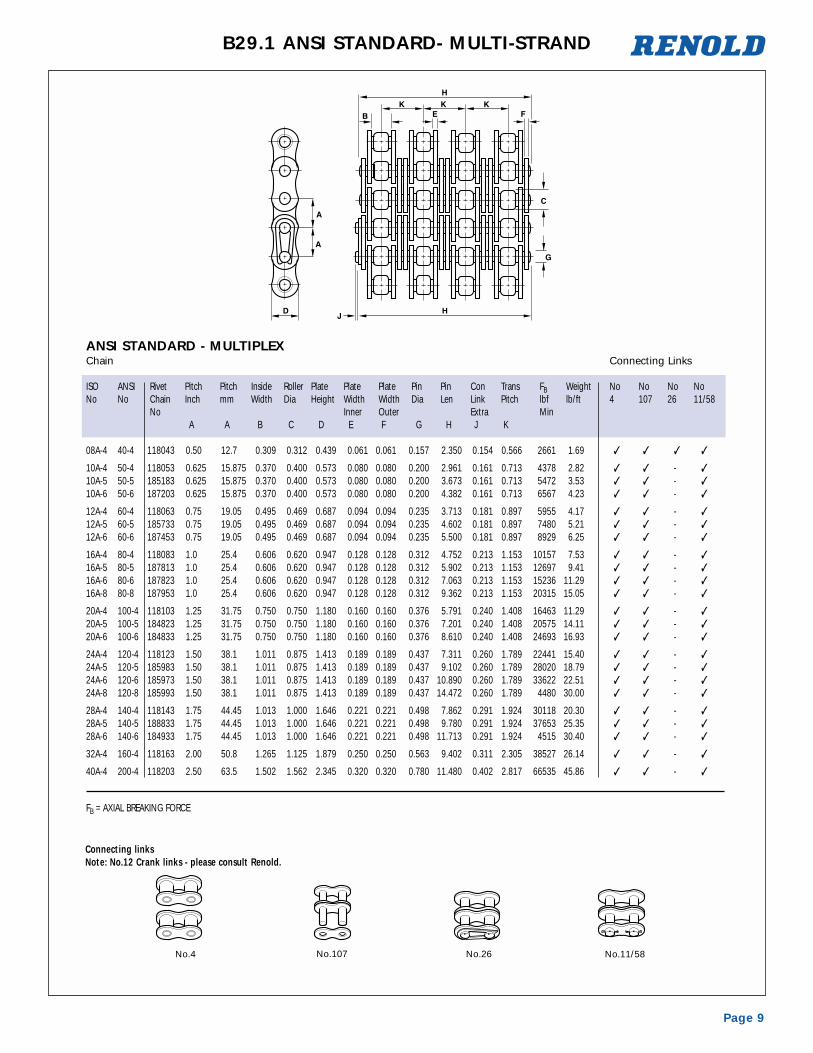
B29.1 ANSI STANDARD- MULTI-STRAND
No.11/58
ANSI STANDARD - MULTIPLEXChain Connecting Links
ISO ANSI Rivet Pitch Pitch Inside Roller Plate Plate Plate Pin Pin Con Trans FB Weight No No No NoNo No Chain Inch mm Width Dia Height Width Width Dia Len Link Pitch lbf lb/ft 4 107 26 11/58
No Inner Outer Extra Min A A B C D E F G H J K
08A-4 40-4 118043 0.50 12.7 0.309 0.312 0.439 0.061 0.061 0.157 2.350 0.154 0.566 2661 1.69 ✓ ✓ ✓ ✓
10A-4 50-4 118053 0.625 15.875 0.370 0.400 0.573 0.080 0.080 0.200 2.961 0.161 0.713 4378 2.82 ✓ ✓ - ✓
10A-5 50-5 185183 0.625 15.875 0.370 0.400 0.573 0.080 0.080 0.200 3.673 0.161 0.713 5472 3.53 ✓ ✓ - ✓
10A-6 50-6 187203 0.625 15.875 0.370 0.400 0.573 0.080 0.080 0.200 4.382 0.161 0.713 6567 4.23 ✓ ✓ - ✓
12A-4 60-4 118063 0.75 19.05 0.495 0.469 0.687 0.094 0.094 0.235 3.713 0.181 0.897 5955 4.17 ✓ ✓ - ✓
12A-5 60-5 185733 0.75 19.05 0.495 0.469 0.687 0.094 0.094 0.235 4.602 0.181 0.897 7480 5.21 ✓ ✓ - ✓
12A-6 60-6 187453 0.75 19.05 0.495 0.469 0.687 0.094 0.094 0.235 5.500 0.181 0.897 8929 6.25 ✓ ✓ - ✓
16A-4 80-4 118083 1.0 25.4 0.606 0.620 0.947 0.128 0.128 0.312 4.752 0.213 1.153 10157 7.53 ✓ ✓ - ✓
16A-5 80-5 187813 1.0 25.4 0.606 0.620 0.947 0.128 0.128 0.312 5.902 0.213 1.153 12697 9.41 ✓ ✓ - ✓
16A-6 80-6 187823 1.0 25.4 0.606 0.620 0.947 0.128 0.128 0.312 7.063 0.213 1.153 15236 11.29 ✓ ✓ - ✓
16A-8 80-8 187953 1.0 25.4 0.606 0.620 0.947 0.128 0.128 0.312 9.362 0.213 1.153 20315 15.05 ✓ ✓ - ✓
20A-4 100-4 118103 1.25 31.75 0.750 0.750 1.180 0.160 0.160 0.376 5.791 0.240 1.408 16463 11.29 ✓ ✓ - ✓
20A-5 100-5 184823 1.25 31.75 0.750 0.750 1.180 0.160 0.160 0.376 7.201 0.240 1.408 20575 14.11 ✓ ✓ - ✓
20A-6 100-6 184833 1.25 31.75 0.750 0.750 1.180 0.160 0.160 0.376 8.610 0.240 1.408 24693 16.93 ✓ ✓ - ✓
24A-4 120-4 118123 1.50 38.1 1.011 0.875 1.413 0.189 0.189 0.437 7.311 0.260 1.789 22441 15.40 ✓ ✓ - ✓
24A-5 120-5 185983 1.50 38.1 1.011 0.875 1.413 0.189 0.189 0.437 9.102 0.260 1.789 28020 18.79 ✓ ✓ - ✓
24A-6 120-6 185973 1.50 38.1 1.011 0.875 1.413 0.189 0.189 0.437 10.890 0.260 1.789 33622 22.51 ✓ ✓ - ✓
24A-8 120-8 185993 1.50 38.1 1.011 0.875 1.413 0.189 0.189 0.437 14.472 0.260 1.789 4480 30.00 ✓ ✓ - ✓
28A-4 140-4 118143 1.75 44.45 1.013 1.000 1.646 0.221 0.221 0.498 7.862 0.291 1.924 30118 20.30 ✓ ✓ - ✓
28A-5 140-5 188833 1.75 44.45 1.013 1.000 1.646 0.221 0.221 0.498 9.780 0.291 1.924 37653 25.35 ✓ ✓ - ✓
28A-6 140-6 184933 1.75 44.45 1.013 1.000 1.646 0.221 0.221 0.498 11.713 0.291 1.924 4515 30.40 ✓ ✓ - ✓
32A-4 160-4 118163 2.00 50.8 1.265 1.125 1.879 0.250 0.250 0.563 9.402 0.311 2.305 38527 26.14 ✓ ✓ - ✓
40A-4 200-4 118203 2.50 63.5 1.502 1.562 2.345 0.320 0.320 0.780 11.480 0.402 2.817 66535 45.86 ✓ ✓ - ✓
FB = AXIAL BREAKING FORCE
No.107 No.26No.4
Connecting linksNote: No.12 Crank links - please consult Renold.
Page 10
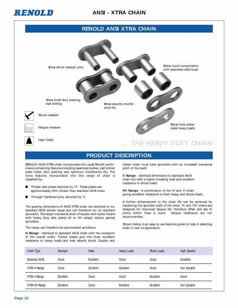
ANSI - XTRA CHAIN
RENOLD ANSI XTRA chain incorporates the usual Renold perfor-mance enhancing features including seamless bushes, ball driftedplate holes, shot peening and optimum interference fits. Theextra features incorporated into this range of chain is classified by:
■ Thicker side plates denoted by 'H'. These plates are approximately 20% thicker than standard ANSI chain.
■ Through hardened pins, denoted by 'V'.
The gearing dimensions of ANSI XTRA chain are identical to ourstandard ANSI simple range and will therefore run on standardsprockets. The larger transverse pitch of duplex and triplex chainswith heavy duty side plates (H or HV range) require specialsprockets.
The range can therefore be summarized as follows:
H Range - Identical to standard ANSI chain with the exceptionof the overall width. Thicker plates give this chain excellent resistance to heavy loads and help absorb shock. Duplex and
triplex chain must have sprockets with an increased transversepitch of the teeth.
V Range - Identical dimensions to standard ANSI chain but with a higher breaking load and excellent resistance to shock loads.
HV Range - A combination of the 'H' and 'V' chain, giving excellent resistance to both heavy and shock loads.
A further enhancement to the chain life can be achieved by hardening the sprocket teeth of the drive. 'H' and 'HV' chains aredesigned for improved fatigue life, therefore offset and slip fitjoints which have a lower fatigue resistance are not recommended.
Shown below is an easy to use features guide to help in selectingchain to suit its application.
RENOLD ANSI XTRA CHAIN
PRODUCT DESCRIPTION
Chain Type Strength Wear Heavy Loads Shock Loads High Speeds
Standard ANSI Good Excellent Good Good Excellent
XTRA H Range Good Excellent Excellent Good Not Suitable
XTRA V Range Excellent Good Good Excellent Good
XTRA HV Range Excellent Good Excellent Excellent Not Suitable
... THE HEAVY DUTY CHAIN
Xtra shock resistant pins
Xtra finish shot peening ball drifting Xtra security interfer-
ence fits
Xtra round componentswith seamless roller/bush
Xtra thick platesresist heavy loads
High loads
Fatigue resistant
Shock resistant

Page 11
B29.1 ANSI - XTRA CHAIN
Part Number: See table below.
Application: ANSI XTRA roller chain is specifically designedand manufactured for arduous applicationswhere frequent, impulsive or heavy loads areinvolved, or where operating conditions aresevere as in the mining, quarrying, rockdrilling, forestry and construction industries.
This chain is interchangeable with our standard ANSI range and can be used to upgrade the performance of existing applications subject to normal design andinstallation checks.
Multiplex versions are also available onrequest.
RENOLD ANSI XTRA CHAIN
Chain Connecting Links
ANSI Renold Pitch Pitch Inside Roller Plate Plate Plate Pin Pin Con FB Weight No No NoNo Chain Inch mm Width Dia Height Width Width Dia Len Link lbf lb/ft 4 107 58
No Inner Outer Extra Min A A B C D E F G H1 J
60H 187661 0.75 19.05 0.500 0.469 0.689 0.125 0.125 0.234 1.126 0.181 8740 1.21 ✓ ✓ ✓
60HV 187666 0.75 19.05 0.500 0.469 0.689 0.125 0.125 0.234 1.126 0.181 12650 1.21 ✓ ✓ ✓
80H 189531 1.00 25.40 0.625 0.625 0.947 0.156 0.156 0.312 1.457 0.213 14900 2.22 ✓ ✓ ✓
80V 189546 1.00 25.40 0.625 0.625 0.947 0.128 0.128 0.312 1.398 0.213 17250 1.88 ✓ ✓ ✓
80HV 189541 1.00 25.40 0.625 0.625 0.947 0.156 0.156 0.312 1.457 0.213 20000 2.22 ✓ ✓ ✓
100H 188556 1.25 31.75 0.750 0.750 1.180 0.187 0.187 0.375 1.736 0.240 24000 3.23 ✓ ✓ ✓
100V 188576 1.25 31.75 0.750 0.750 1.180 0.156 0.156 0.375 1.618 0.240 28100 2.82 ✓ ✓ ✓
100HV 188566 1.25 31.75 0.750 0.750 1.180 0.187 0.187 0.375 1.736 0.240 30700 3.23 ✓ ✓ ✓
120H 188661 1.50 38.10 1.000 0.875 1.413 0.219 0.219 0.437 2.130 0.260 32660 4.23 ✓ ✓ ✓
120V 188676 1.50 38.10 1.000 0.875 1.413 0.187 0.187 0.437 2.000 0.260 38900 3.83 ✓ ✓ ✓
120HV 188671 1.50 38.10 1.000 0.875 1.413 0.219 0.219 0.437 2.130 0.260 42000 4.23 ✓ ✓ ✓
140H 188716 1.75 44.45 1.000 1.000 1.646 0.250 0.250 0.500 2.280 0.291 44000 5.78 ✓ ✓ ✓
140V 188736 1.75 44.45 1.000 1.000 1.646 0.219 0.219 0.500 2.161 0.291 54000 5.24 ✓ ✓ ✓
140HV 188726 1.75 44.45 1.000 1.000 1.646 0.250 0.250 0.500 2.280 0.291 59500 5.78 ✓ ✓ ✓
160H 188731 2.00 50.80 1.250 1.125 1.879 0.281 0.281 0.562 2.697 0.311 56300 7.53 ✓ ✓ ✓
160V 188746 2.00 50.80 1.250 1.125 1.879 0.250 0.250 0.562 2.579 0.311 66500 6.99 ✓ ✓ ✓
160HV 188741 2.00 50.80 1.250 1.125 1.879 0.281 0.281 0.562 2.697 0.311 71700 7.53 ✓ ✓ ✓
180H 188761 2.25 57.15 1.406 1.406 2.107 0.312 0.312 0.687 3.068 0.358 75100 10.22 ✓ ✓ ✓
180V 188756 2.25 57.15 1.406 1.406 2.107 0.281 0.281 0.687 2.909 0.358 88000 9.37 ✓ ✓ ✓
180HV 188771 2.25 57.15 1.406 1.406 2.107 0.312 0.312 0.687 3.068 0.358 97200 10.22 ✓ ✓ ✓
200H 188781 2.50 63.50 1.500 1.562 2.345 0.375 0.375 0.781 3.402 0.402 97200 13.10 ✓ ✓ ✓
200V 188776 2.50 63.50 1.500 1.562 2.345 0.312 0.312 0.781 3.161 0.402 102400 11.63 ✓ ✓ ✓
200HV 188791 2.50 63.50 1.500 1.562 2.345 0.375 0.375 0.781 3.402 0.402 138200 13.10 ✓ ✓ ✓
FB = AXIAL BREAKING FORCE
No.4 No.107 No.58

Page 12
ANSI DOUBLE PITCH - SIMPLE
ANSI STANDARDChain Connecting Links
ANSI Renold Pitch Pitch Inside Roller Plate Plate Plate Pin Pin Con FB Weight No No No NoNo Chain Inch mm Width Dia Height Width Width Dia Len Link lbf lbs 4 107 11/58 12
No Inner Outer Extra Min A A B C D E F G H J
2040 113040 1.00 25.40 1.00 0.309 0.313 0.472 0.059 0.156 0.701 0.154 3170 0.27 ✓ ✓ ✓ ✓
2050 113050 1.25 31.75 1.25 0.370 0.400 0.591 0.079 0.200 0.858 0.161 4991 0.47 ✓ ✓ ✓ ✓
2060 113060 1.50 38.10 1.50 0.495 0.469 0.709 0.094 0.234 1.059 0.181 8542 0.71 ✓ ✓ ✓ ✓
FB= AXIAL BREAKING FORCE
No.107 No.11/58 No.12No.4

Page 13
ANSI - SYNO
Renold Syno Chain combines the technology of a radical new built-in lube system,
with the proven precision components of Renold Chain.
It is ideal for chain applications requiring a clean environment, or where maintenance
is difficult.
■ A new technology self-lubricating system.
■ Direct replacement for standard oiled chains on existing sprockets.
■ High performance ratings.
■ Available for drive chains and conveyor attachment chains.
■ Solid, durable gearing rollers reduce noise and sprocket wear.
■ BS/ANSI chains available.
■ Significantly lower maintenance costs.
■ Up to double wear life of other lube free chains.
■ Extended chain life compared to standard chains (up to 15 times longer than standard chains when run unlubricated).
■ Application and disposal of expensive lubricants not required.
■ Provides a clean environment around the chain drive/conveyor.
■ Reduces hazards caused by waste lubricants.
■ Operating temperature range -10˚ to +70˚C.
RENOLD SYNO LUBE FREE CHAIN
Renold Syno is also suitable for: bookbinding, canning plants, electronics assembly,food packaging, food preparation plants, paper and tissue manufacture, pet food processing, pharmaceutical industry, printing/carton equipment, textiles andclothing manufacture.
FB = Axial Breaking Force
N.B Renold Syno does not conform exactly to ANSI standards. A larger bush and thus a smaller pin diameter are needed to meet the high performance requirements.However, all gearing dimensions of Renold Syno do comply with ANSI standards. Consult Renold for specific requirements.
RENOLD SYNO ANSI Standard Lube free chain - Simple Chain Connecting Links
ANSI Renold Pitch Pitch Inside Roller Plate Plate Plate Pin Pin Con FB Weight No No No NoNo Chain Inch mm Width Dia Height Width Width Dia Len Link lbf lb/ft 4 107 26 11
No Inner Outer Extra Min.A A B C D E F G H1 J
40 119443 0.500 12.70 0.312 0.312 0.461 0.071 0.059 0.156 0.665 0.067 4000 0.47 ✓ ✓ ✓ -50 119453 0.625 15.87 0.375 0.375 0.575 0.079 0.079 0.175 0.803 0.098 5200 0.74 ✓ ✓ - ✓
60 119463 0.750 19.05 0.500 0.500 0.657 0.094 0.094 0.200 0.996 0.098 6900 1.01 ✓ ✓ - ✓
80 119483 1.000 25.40 0.625 0.625 0.795 0.146 0.118 0.276 1.378 0.161 14700 1.68 ✓ ✓ - ✓
10 15 20 30 40 50 60 70 80 90 100
150
200
300
400
500
600
700
800
900
1000
10.09.08.07.06.0
5.0
4.0
3.0
2.0
1.5
1.00.90.80.70.6
0.5
0.4
0.3
0.2
0.15
0.1

Page 14
ANSI - CORIS
No.4 No.107 No.11 No.26 No.12(Simple Only)
Renold Coris Roller Chain is manufactured using Class 300 Seriesstainless steel specification. These chains are ideal for acidic oralkaline environments, or where the chain will be exposed towater, and for very high or very low temperature locations, whereresistance to corrosion is a requirement.
Renold Coris Chain should be selected when resistance to chemical action is critical. Renold Coris is manufactured usingFDA approved material and is pre-lubricated with USDA HIapproved lubricant.
Chain Connecting Links
ANSI Renold Pitch Pitch Inside Roller Plate Plate Plate Pin Pin Con Trans FB Weight No No No No No NoNo Chain Inch mm Width Dia Height Width Width Dia Len Link Pitch lbf lb/ft 4 107 11 26 58 12
No Inner Outer Extra Min A A B C D E F G H1 J K
35 545351 0.375 9.525 0.188 0.200 0.341 0.050 0.050 0.141 0.610 0.130 - 1700 0.22 ✓ ✓ - ✓ - ✓
40 545401 0.500 12.700 0.312 0.312 0.439 0.060 0.060 0.156 0.701 0.154 - 2400 0.42 ✓ ✓ ✓ ✓ - ✓
50 545501 0.625 15.875 0.375 0.400 0.573 0.080 0.080 0.200 0.858 0.161 - 3800 0.71 ✓ ✓ ✓ ✓ - ✓
60 545601 0.750 19.050 0.500 0.469 0.687 0.094 0.094 0.234 1.059 0.181 - 5400 1.04 ✓ ✓ ✓ ✓ - ✓
80 545801 1.000 25.400 0.625 0.625 0.947 0.125 0.125 0.312 1.319 0.213 - 11500 1.88 ✓ ✓ ✓ - - ✓
RENOLD CORIS ANSI standard stainless steel chain - Simple
40-2 545402 0.500 12.700 0.312 0.312 0.439 0.060 0.060 0.156 1.267 0.154 - 4800 0.81 ✓ ✓ ✓ ✓ -50-2 545502 0.625 15.875 0.375 0.400 0.573 0.080 0.080 0.200 1.570 0.161 - 7600 1.41 ✓ ✓ ✓ ✓ -60-2 545602 0.750 19.050 0.500 0.469 0.687 0.094 0.094 0.234 1.961 0.181 - 10800 2.05 ✓ ✓ ✓ ✓ -80-2 545802 1.000 25.400 0.625 0.625 0.947 0.125 0.125 0.312 2.469 0.213 - 23000 3.70 ✓ ✓ ✓ - -
RENOLD CORIS ANSI standard stainless steel chain - Duplex
RENOLD CORIS STAINLESS STEEL CHAIN
FB = Axial Breaking Force

Page 15
B29.1 ANSI STANDARD - ATTACHMENTS
RENOLD ANSI STANDARD M1 ATTACHMENTS
M1 ATTACHMENTS
ISO/ANSI STANDARD M1 ATTACHMENTS
ANSI Renold Pitch PitchNo Chain Inch mm
NoA A E F L M N P Q
40 119043 0.500 12.700 0.059 0.059 0.375 0.689 0.500 0.130 0.21750 119053 0.625 15.875 0.079 0.079 0.500 0.969 0.625 0.209 0.28360 119063 0.750 19.050 0.094 0.094 0.625 1.079 0.720 0.209 0.33980 119083 1.000 25.400 0.118 0.118 0.945 1.563 0.969 0.260 0.476
ANSI Renold Pitch PitchNo Chain Inch mm
NoA A E F L M N P Q
40 119043 0.500 12.700 0.060 0.060 0.375 0.685 0.489 0.125 0.23750 119053 0.625 15.875 0.080 0.080 0.500 0.895 0.618 0.205 0.29760 119063 0.750 19.050 0.094 0.094 0.625 1.038 0.716 0.205 0.35680 119083 1.000 25.400 0.125 0.125 0.750 1.350 0.968 0.265 0.450

Page 16
B29.1 ANSI STANDARD - ATTACHMENTS
ANSI Renold Pitch PitchNo Chain Inch mm
NoA A E F M N P Q R S
40 119043 0.500 12.700 0.059 0.059 0.689 0.500 0.130 0.217 0.945 0.50050 119053 0.625 15.875 0.079 0.079 0.969 0.625 0.209 0.283 1.177 0.62560 119063 0.750 19.050 0.094 0.094 1.079 0.720 0.209 0.339 1.402 0.75080 119083 1.000 25.400 0.118 0.118 1.563 0.969 0.260 0.476 1.819 1.000
RENOLD ANSI STANDARD M2 ATTACHMENTS
M2 ATTACHMENTS
Page 17
B29.1 ANSI STANDARD - ATTACHMENTS
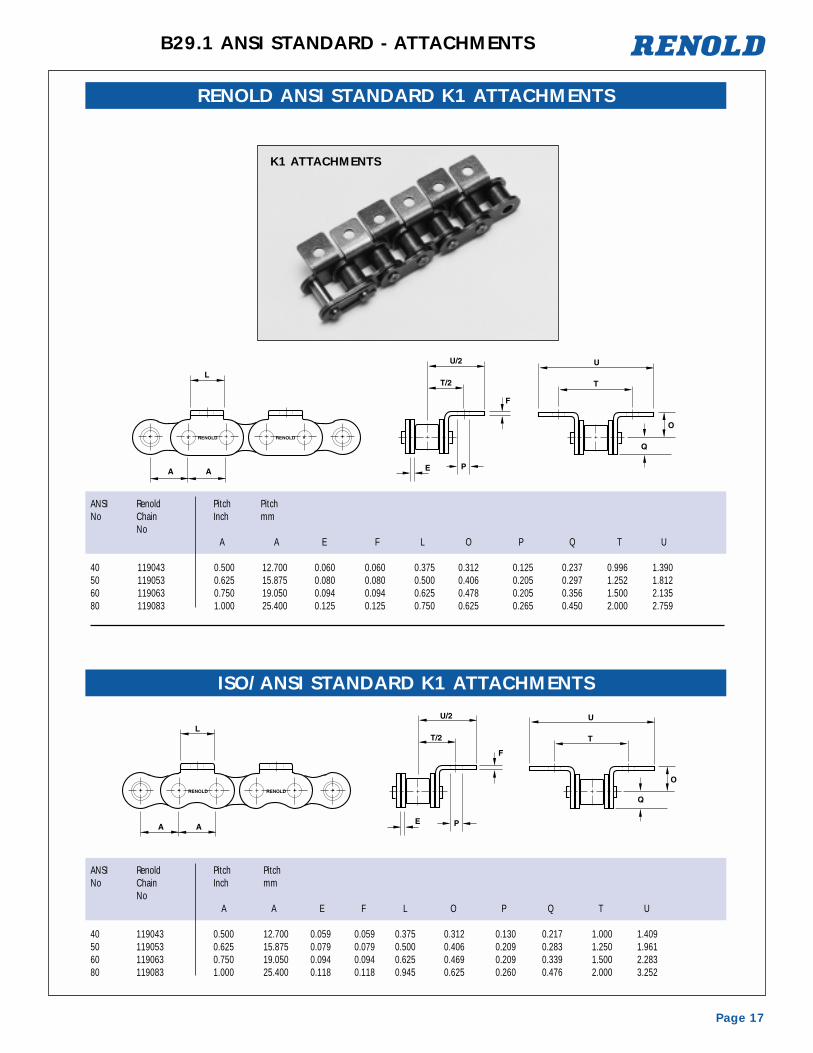
RENOLD ANSI STANDARD K1 ATTACHMENTS
K1 ATTACHMENTS
ANSI Renold Pitch PitchNo Chain Inch mm
NoA A E F L O P Q T U
40 119043 0.500 12.700 0.059 0.059 0.375 0.312 0.130 0.217 1.000 1.40950 119053 0.625 15.875 0.079 0.079 0.500 0.406 0.209 0.283 1.250 1.96160 119063 0.750 19.050 0.094 0.094 0.625 0.469 0.209 0.339 1.500 2.28380 119083 1.000 25.400 0.118 0.118 0.945 0.625 0.260 0.476 2.000 3.252
ISO/ANSI STANDARD K1 ATTACHMENTS
ANSI Renold Pitch PitchNo Chain Inch mm
NoA A E F L O P Q T U
40 119043 0.500 12.700 0.060 0.060 0.375 0.312 0.125 0.237 0.996 1.39050 119053 0.625 15.875 0.080 0.080 0.500 0.406 0.205 0.297 1.252 1.81260 119063 0.750 19.050 0.094 0.094 0.625 0.478 0.205 0.356 1.500 2.13580 119083 1.000 25.400 0.125 0.125 0.750 0.625 0.265 0.450 2.000 2.759

Page 18
B29.1 ANSI STANDARD - ATTACHMENTS
ANSI Renold Pitch PitchNo Chain Inch mm
NoA A E F O P Q R S T U
40 119043 0.500 12.700 0.059 0.059 0.311 0.130 0.217 0.945 0.500 1.000 1.40950 119053 0.625 15.875 0.079 0.079 0.406 0.209 0.283 1.177 0.625 1.250 1.96160 119063 0.750 19.050 0.094 0.094 0.469 0.209 0.339 1.402 0.750 1.500 2.28380 119083 1.000 25.400 0.118 0.118 0.625 0.260 0.476 1.819 1.000 2.000 3.252
RENOLD ANSI STANDARD K2 ATTACHMENTS
K2 ATTACHMENTS
Page 19
B29.1 ANSI STANDARD - EXTENDED BEARING PINS
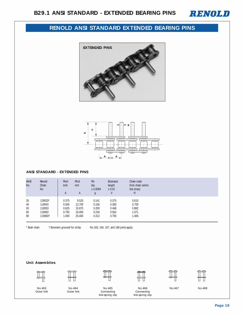
RENOLD ANSI STANDARD EXTENDED BEARING PINS
EXTENDED PINS
ANSI STANDARD - EXTENDED PINS
Unit Assemblies
ANSI Renold Pitch Pitch Pin Extension Chain trackNo Chain Inch mm dia. length from chain centre
No ± 0.0004 ± 0.01 line (max)A A g V H
35 129033* 0.375 9.525 0.141 0.375 0.61040 119043 0.500 12.700 0.156 0.383 0.70950 119053 0.625 15.875 0.200 0.468 0.88260 119063 0.750 19.050 0.234 0.562 1.07180 119083† 1.000 25.400 0.312 0.750 1.406
* Bush chain † Extension grooved for circlip No.163, 164, 167, and 168 joints apply.
No.463Outer link
No.465Connecting
link-spring clip
No.467No.464Outer link
No.466Connecting
link-spring clip
No.468

Page 20
B29.1 ANSI - CONNECTING LINKS
SPECIAL OR ADAPTED TRANSMISSION CHAINIn addition to our ranges of standardseries chain we can also offer:
■ Transmission Chain up to 11.75 in. pitch and 500 tonbreaking load.
■ Standard Series Chain adapted to your unique needs with special attachments.
■ Special Chain designed with integral attachments to meet individual requirements.
Renold Adapted Chain can be in the form of special plates, pin rollers, or blocks whichcan be designed, manufactured and assembled into chain of all pitch sizes.
Attachments can be made from normal materials, stainless steel or plastics.
We will be pleased to receive details of your requirements and evaluate them forstrength, durability, price and despatch. They can be manufactured from your owndesigns or adapted from existing drawings.
The illustrations show only a small selection of the wide range of variants and thesechains have been used successfully in many branches of industry for the feeding, conveying and discharge of a variety of products.
ATTACHMENT CONNECTING LINKS FOR ANSI SIMPLE ROLLER CHAIN
No240 No140
No270 No170
No272 No172 No144
No278
No175
No178 No174 No181
No242 No142No276 No176 No145 No180
No164*
* ANSI 80
No163* No167*
No168*
No463
No464
No465
No466