CAD Japanese Standard
178
ERDC/ITLTR-01-6 September 2001 The CADD/GIS Technology Center for facilities, infrastructure, and environment A/E/C CADD Standard Main Text and Appendices A, B, and C Release 2.0 Approved For Public Release; Distribution Is Unlimited The A/E/C CADD Standard is ^fj compliant with Version 2.0 of the U.S. National CAD Standard. The A/E/C CADD Standard contains supplemental materials g^> and DoD specific requirements not addressed in the U.S. National CAD Standard. 20011231 100 Published for U.S. Army Engineer Research and Development Center
description
important janpanese standard
Transcript of CAD Japanese Standard
ERDC/ITLTR-01-6 September 2001
The CADD/GIS Technology Center for facilities, infrastructure, and environment
A/E/C CADD Standard
Main Text and Appendices A, B, and C
Release 2.0
Approved For Public Release; Distribution Is Unlimited
The A/E/C CADD Standard is ^fj compliant with Version 2.0
of the U.S. National CAD Standard.
The A/E/C CADD Standard contains supplemental materials g^>
and DoD specific requirements not addressed in the U.S. National
CAD Standard.
20011231 100 Published for U.S. Army Engineer Research and Development Center
The contents of this report are not to be used for advertising, pub- lication, or promotional purposes. Citation of trade names does not constitute an official endorsement or approval of the use of such commercial products.
The findings of this report are not to be construed as an official Department of the Army position, unless so designated by other authorized documents.
$ PRINTED ON RECYCLED PAPER
ERDC/ITLTR-01-6 September 2001
A/E/C CADD Standard
Main Text and Appendices A, B, and C «f-; *!** ,^'. J»>. W;. «*■-' .^^jT f *
Release 2.0
Approved for public release; distribution is unlimited
Published by U.S. Army Engineer Research and Development Center 3909 Halls Ferry Road, Vicksburg, MS 39180-6199
Contents
Preface vin
1 — Introduction
Acronyms Scope Purpose Background 2
International System of Units (SI) Considerations 2 Future Technologies 2
Interchangeable Terminology 3
Target Systems 3
Additions/Revisions ■>
2 — Drawing File Organization 5
Design Cube 5
Available drawing area -> File accuracy (units) " Drawing units/working units recommendations 6 Origin (global origin) °
Model Files and Sheet Files 7
Electronic Drawing File Naming Conventions 8
Model file naming convention 8 Sheet file naming convention 12
Coordination Between Sheet File Name and Sheet Identifier IV
3 — Graphic Concepts *"
Presentation Graphics *" Line widths ^" Line types/styles 20 Line color *•*■ Screening o
21
Text styles/fonts 23 Plotting 23
Border Sheets 23 Sheet sizes 23
Title block 25 Drawing Scales 27 Dimensioning in Metric (SI) 27
Millimeters 27 Meters 31 Large units of measure 31 Dual units 32
4 — Level/Layer Assignments 33
Levels/Layers 33 Level/layer naming conventions 35 ISO format 35
Model Files 35 Level/layer assignment tables 35 Border sheets 37 Reference files (XREFs) 37
Sheet Files 38 Level/layer assignment tables 38 Development of sheet files 39
5 — Standard Symbology 41
Introduction 41 Electronic Version of the Symbology/Elements 41
Deliverables 41 Line styles 41
Tabulated Version of the Symbology/Elements 41
6 — A/E/C CADD Standard Implementation Tools 44
References 47
Appendix A: Model File Level/Layer Assignment Tables Al
Appendix B: Sheet File Level/Layer Assignment Tables Bl
Appendix C: Color Comparison Cl
Appendix D1: A/E/C CADD Symbology Dl
SF 298
Bound separately.
IV
List of Figures
Figure 1. Available drawing size 5
Figure 2. AutoCAD Units Dialog Box 6
Figure 3. Origins in MicroStation and AutoCAD 7
Figure 4. Sheet file composition 8
Figure 5. Model file naming convention 9
Figure 6. Sheet file naming convention *7
Figure 7. Typical border sheet title block with sheet identification block 18
Figure 8. Sample metric drawing sheet with vertical title block 26
Figure 9. Designer identification block (typ.) 26
Figure 10. Issue block (typ.) 26
Figure 11. Management block (typ.) 26
Figure 12. Project identification block/sheet title block 27
Figure 13. Sheet identification block 27
Figure 14. Dimension in millimeters 31
Figure 15. Dimension in meters 31
Figure 16. Proper dimension presentations for metric measurements with four or more digits 31
Figure 17. Unit format 31
Figure 18. Typical levels/layers contained in a sheet file 33
Figure 19. Sheet- and model-specific information 34
Figure 20. Level/layer naming format methods 35
Figure 21. ISO 13567-2 level/layer naming method 36
Figure 22. Model file level/layer assignment table 37
Figure 23. Using referenced model files to build a new model file without redundant effort 38
Figure 24. Sheet file level/layer assignment table 39
Figure 25. Using multiple referenced model files to build a sheet file without redundant effort 40
Figure 26. Symbology directory structure 42
Figure 27. Line element 43
Figure 28. Pattern element 43
Figure 29. Symbol element 43
Figure 30. Object element 43
Figure 31. MicroStation workspace 45
Figure 32. Workspace checker 46
Figure 33. AutoCAD workspace 46
List of Tables
Table 1. Interchangeable Terminology 4
Table 2. MicroStation Working Units and Global Origins 7
Table 3. Discipline Designators 9
Table 4. Model File Types 10
Table 5. Discipline Designators with Level 2 Designators 13
Table 6. Sheet Type Designators 17
Table 7. Comparison of Line Widths 19
Table 8. Standard Line Types/Styles 20
Table 9. Screen Color Comparison 21
Table 10. Screened Colors 22
VI
Table 11. Comparison of Font Types 24
Table 12. ISO, ANSI, and Architectural Sheet Size Comparison 25
Table 13. Drawing Scales 28
Table 14. Inch-pound Text Sizes 29
Table 15. Metric Text Sizes 30
VII
Preface
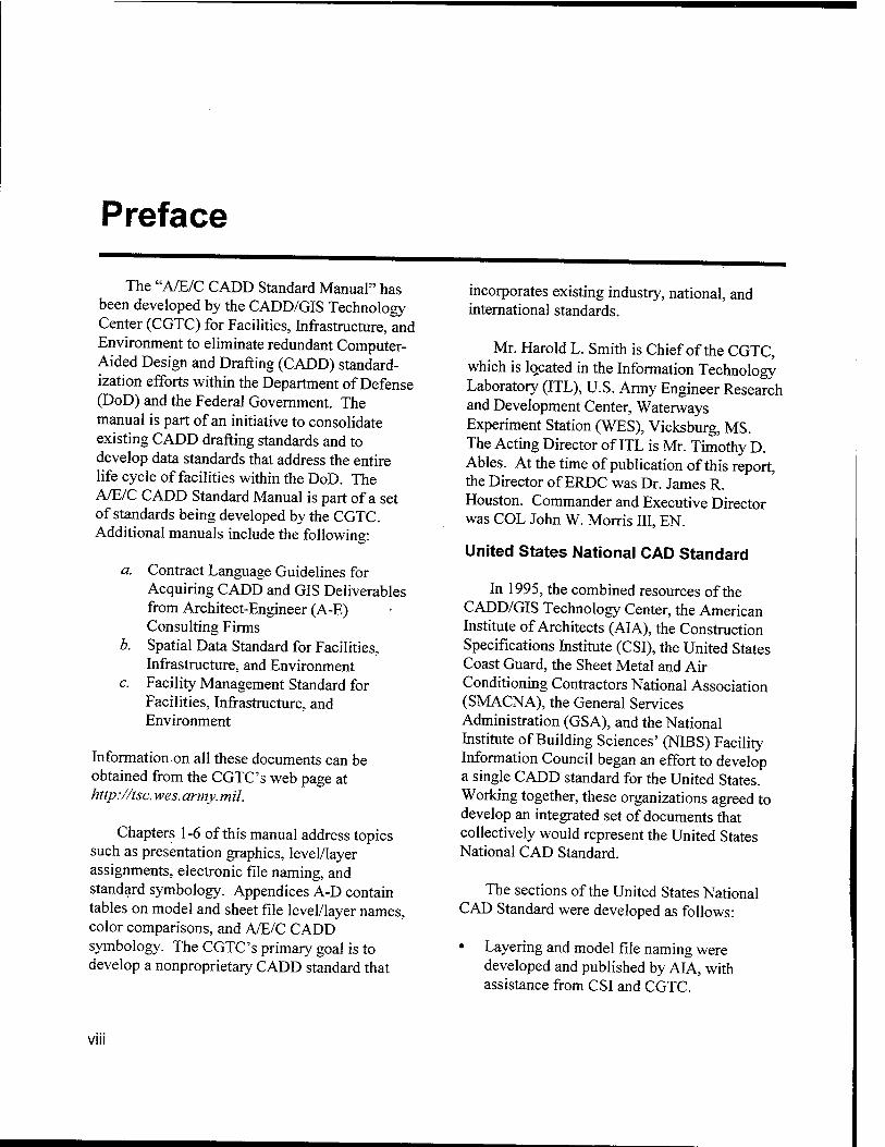
The "A/E/C CADD Standard Manual" has been developed by the CADD/GIS Technology Center (CGTC) for Facilities, Infrastructure, and Environment to eliminate redundant Computer- Aided Design and Drafting (CADD) standard- ization efforts within the Department of Defense (DoD) and the Federal Government. The manual is part of an initiative to consolidate existing CADD drafting standards and to develop data standards that address the entire life cycle of facilities within the DoD. The A/E/C CADD Standard Manual is part of a set of standards being developed by the CGTC. Additional manuals include the following:
Contract Language Guidelines for Acquiring CADD and GIS Deliverables from Architect-Engineer (A-E) Consulting Firms Spatial Data Standard for Facilities, Infrastructure, and Environment Facility Management Standard for Facilities, Infrastructure, and Environment
b.
c.
Information.on all these documents can be obtained from the CGTC's web page at http://tsc. wes. army.mil.
Chapters 1-6 of this manual address topics such as presentation graphics, level/layer assignments, electronic file naming, and standard symbology. Appendices A-D contain tables on model and sheet file level/layer names, color comparisons, and A/E/C CADD symbology. The CGTC's primary goal is to develop a nonproprietary CADD standard that
incorporates existing industry, national, and international standards.
Mr. Harold L. Smith is Chief of the CGTC, which is located in the Information Technology Laboratory (ITL), U.S. Army Engineer Research and Development Center, Waterways Experiment Station (WES), Vicksburg, MS. The Acting Director of ITL is Mr. Timothy D. Abies. At the time of publication of this report, the Director of ERDC was Dr. James R. Houston. Commander and Executive Director was COL John W. Morris III, EN.
United States National CAD Standard
In 1995, the combined resources of the CADD/GIS Technology Center, the American Institute of Architects (AIA), the Construction Specifications Institute (CSI), the United States Coast Guard, the Sheet Metal and Air Conditioning Contractors National Association (SMACNA), the General Services Administration (GSA), and the National Institute of Building Sciences' (NIBS) Facility Information Council began an effort to develop a single CADD standard for the United States. Working together, these organizations agreed to develop an integrated set of documents that collectively would represent the United States National CAD Standard.
The sections of the United States National CAD Standard were developed as follows:
• Layering and model file naming were developed and published by AIA, with assistance from CSI and CGTC.
VIII
• Drawing set organization and sheet file naming were developed and published by CSI, assisted by CGTC, and reviewed by AIA.
• Sheet organization was developed and published by CSI, with assistance from AIA and CGTC.
• Schedules were developed and published by CSI, assisted by CGTC, and reviewed by AIA.
• Plotting guidelines (colors and line weights) were developed by CGTC and the United States Coast Guard, and reviewed by CSI and AIA.
• Drafting conventions including notations, symbols, diagrams, scales, and line types were developed by CSI, CGTC, the United States Coast Guard, and SMACNA; assisted by AIA; and published by CSI.
• Nongraphic attributes will be developed and published by CGTC, the International Alliance for Interoperability (IAI), vendors, and trade associations, with review by CSI and AIA.
A Memorandum of Understanding (MOU) was signed on August 8, 1997. In accordance with that MOU, Release 2.0 of the A/E/C CADD Standard follows, utilizes, or references the work developed by each of the signatories. The two main documents referenced within Release 2.0 of the A/E/C CADD Standard are
• "The Uniform Drawing System" The Construction Specifications Institute 601 Madison Street Alexandria, VA 22314-1791 http://www. csinet. org
• "AIA CAD Layer Guidelines" The American Institute of Architects Press 1735 New York Avenue, N. W. Washington, DC 20006 http://www. aiaonline. com/
Each of these documents can currently be obtained from the authoring agency or can be purchased together as part of the United States National CAD Standard. Additional informa- tion on the United States National CAD Standard can be obtained from
• NIBS Facility Information Council National Institute of Building Sciences 1090 Vermont Avenue, N. W., Suite 700 Washington, DC 20005-4905 http://www. nationalcadstandard. org
The contents of this report are not to be used for advertising, publication, or promotional purposes. Citation of trade names does not constitute an official endorsement or approval of the use of such commercial products.
IX
1 Introduction
Acronyms
First, a few useful acronyms:
A-E - Architect-Engineer
A/E/C - Architectural, Engineering, and Construction
AIA - American Institute of Architects
ANSI - American National Standards Institute
ASTM - American Society for Testing and Materials
CAD - Computer-Aided Design
CADD - Computer-Aided Design and Drafting
CGTC - The CADD/GIS Technology Center
CSI - Construction Specifications Institute
DoD - Department of Defense
FM - Facility Management
GIS - Geographic Information System
IAI - International Alliance for Interoperability
IFC - Industry Foundation Class
IOC - Intelligent Object Class
ISO - International Organization for Standardization
• NCS - National CAD Standard
• NIBS - National Institute of Building Sciences
• SI - International System of Units (Le Systeme International d'Unites)
• UDS - Uniform Drawing System
Scope
This manual provides guidance and procedures for preparing Computer-Aided Design and Drafting (CADD) products within the Department of Defense (DoD).
Chapters 1-6 of this manual address topics such as presentation graphics, level/layer assignments, electronic file naming, and standard symbology. Appendices A-D contain tables on model and sheet file level/layer names, color comparisons, as well as Architectural, Engineering, and Construction (A/E/C) CADD symbology.
Purpose
The purpose of this manual is to set a basic CADD standard to ensure consistent electronic deliverables (products) within the DoD. These consistent deliverables are part of a comprehen- sive installation life-cycle management strategy. This manual sets a CADD standard specifically for the architectural, engineering, and construction disciplines of facilities development and civil works projects. As this manual evolves, it will be integrated with other standards initiatives by the CADD/GIS Technology Center (CGTC) for
Chapter 1 Introduction 1
Facilities, Infrastructure, and Environment such as Contract Language Guidelines, Spatial Data Standards, and Facility Management (FM) Standards.
Background
The immediate benefits of CADD standards are many: consistent CADD products for cus- tomers; uniform requirements for A-E deliver- ables; sharing of products and expertise; and collection, manipulation, and exchange of database information. Recognizing such potential benefits, each of the DoD agencies independently initiated efforts to establish CADD standards in the late 1980's. The Air Force Logistics Command (1989) released the "Architectural and Engineering Services for CADD Implementation Within Air Force Logistics Command." Headquarters, U.S. Army Corps of Engineers (1990), published Engineer Manual 1110-1-1807, "Standards Manual for U.S. Army Corps of Engineers Computer-Aided Design and Drafting (CADD) Systems." In 1993, the Naval Facilities Engineering Command distributed its "Policy and Procedures for Electronic Deliverables of Facilities Computer- Aided Design and Drafting (CADD) Systems."
To consolidate these efforts into a single standard, the CGTC was tasked to develop standards for the A/E/C disciplines includes Civil Works. This manual presents the CGTC's effort at standardizing CADD requirements for A/E/C design and construction documents. To facilitate the use of this standard, supplementary software packages are available that automate the implementation and use of the standard. This software allows the operator to select preset system variables to align with the requirements of the "A/E/C CADD Standard Manual" to ensure consistent and easy compliance with the standard (see Chapter 6, "A/E/C CADD Standard Implementation Tools").
International System of Units (SI) Considerations
For this standard manual, the impact of the SI, more commonly referred to as the metric system, is addressed on such items as drawing scales, sheet sizes, and dimensioning. The SI was established by the General Conference of Weights and Measures of 1960, as interpreted or modified from time to time for the United States by the Secretary of Commerce under the authority of Public Law 94-168, the Metric Conversion Act of 1975, and the Metric Education Act of 1978. As of January 1, 1992, in accordance with Public Laws 94-168 and 100-418, the Omnibus Trade and Competitiveness Act of 1988, and Executive Order 12770, "Metric Usage in Federal Government Programs," July 25, 1991, all new and revised construction standards and criteria must be developed using the SI.
Future Technologies
There are several ongoing initiatives to create a universal language for collaborative work in the area of building and construction software. This work stems from the need to automate current building and construction tasks to become more efficient and cost effective. One of these initia- tives is by the International Alliance for Interoper- ability (IAI), a nonprofit building industry alliance comprising architects, engineers, contractors, software vendors, government agencies, research laboratories, and universities. The goal of the IAI is to unite the A/E/C and FM businesses by specifying Industry Foundation Classes (LFCs) as a universal language. The concept behind the DFCs is to create a series of standard intelligent software objects for the building industry that allow all process disciplines (i.e., architects, designers, engineers, builders, facilities managers) to exchange information. The LAI is developing LFCs that allow current software packages such as AutoCAD and MicroStation to share building and construction data. LFCs would improve the quality of the life-cycle of a building from
Chapter 1 Introduction
construction through maintenance and ultimately to demolition. These improvements would result from reductions in expense and delivery time, enhanced communications, and an increase in discipline proficiency.
A prerequisite of this effort is the deployment of mechanisms capable of retaining knowledge during the project life cycle. Intelligent Object Classes (IOCs) can serve this purpose. An IOC gathers information during the progression of the project and makes it available to the participants. Starting from the design phase, IOCs collect additional data about an object, for example, "how to design" or "how to construct" that particular object. The structure of an IOC contains information about the following:
• Generic attributes of common use (e.g., identification, material).
• Methods to support specialist tasks (e.g., volume calculations).
• CADD representation information including geometry and topology.
• Interrelationships with other objects.
In tandem with the IAI effort, the CGTC is developing nongraphic attribute data as part of the A/E/C CADD Standard.
Interchangeable Terminology
Within the various commercially available CADD systems, many identical or related concepts are given different names. To aid users of this manual, some instances of related or interchangeable terminology used in MicroStation and AutoCAD are listed in Table 1.
Target Systems
This manual is not targeted toward any specific CADD system or software. However, to ensure successful translations among CADD
applications, certain system-specific characteristics were considered and the standard adjusted accordingly. In preparing the standard, several baseline decisions were made:
• The standard must be applicable to the latest release of commercially available CADD packages. AutoCAD and MicroStation were chosen based on their prevalence in the DoD and their availability through the Installation Management/Facilities CAD2 contract.
• The standard is based on CADD applications that utilize layer/level names and reference files.
• The standard requires every final plotted drawing sheet to have its own separate electronic drawing file.
• Since three-dimensional files are not compa- tible with two-dimensional files, it is recom- mended that all drawings be created as 3-D files.
Additions/Revisions
This standard is intended to be neither static nor all-inclusive and thus will be updated and enhanced as appropriate. Suggestions for improvements are strongly encouraged so that subsequent updates will reflect the input and needs of CADD users.
Recommendations or suggested additions should be sent to:
The CADD/GIS Technology Center USAE Research and Development Center,
Waterways Experiment Station ATTN: CEERD-ID-C/Spangler 3909 Halls Ferry Road Vicksburg, MS 39180-6199
Or by e-mail at: [email protected]
Chapter 1 Introduction
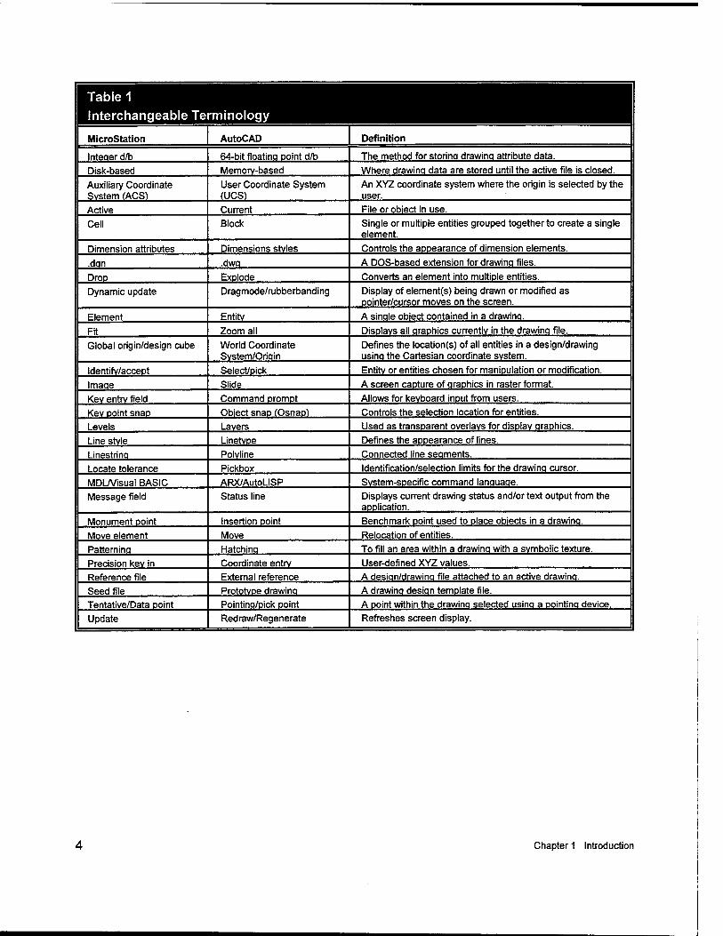
Table 1 Interchangeable Terminology
MicroStation AutoCAD Definition
Inteaer d/b 64-bit floatina Doint d/b The method for storinq drawinq attribute data.
Disk-based Memory-based Where drawinq data are stored until the active file is closed.
Auxiliary Coordinate System (ACS!
User Coordinate System fUCS)
An XYZ coordinate system where the origin is selected by the user.
Active Current File or object in use.
Cell Block Single or multiple entities grouped together to create a single element.
Dimension attributes Dimensions styles Controls the appearance of dimension elements.
.dan .dwa A DOS-based extension for drawinq files.
Drop Explode Converts an element into multiple entities.
Dynamic update Dragmode/rubberbanding Display of element(s) being drawn or modified as pointer/cursor moves on the screen.
Element Entity A sinqle object contained in a drawinq.
Fit Zoom all Displays all qraphics currently in the drawinq file.
Global origin/design cube World Coordinate Svstem/Oriain
Defines the location(s) of all entities in a design/drawing usinq the Cartesian coordinate system.
Identifv/acceot Select/Dick Entity or entities chosen for manipulation or modification.
Imaqe Slide A screen capture of qraphics in raster format.
Kev entrv field Command prompt Allows for keyboard input from users.
Kev Doint snap Object snap (Osnaol Controls the selection location for entities.
Levels Layers Used as transparent overlays for display qraphics.
Line stvle Linetvoe Defines the appearance of lines.
Linestrina Polyline Connected line seoments.
Locate tolerance Pickbox Identification/selection limits for the drawinq cursor.
MDL/Visual BASIC ARX/AutoLISP Svstem-soecific command lanouaqe.
Message field Status line Displays current drawing status and/or text output from the application.
Monument point Insertion point Benchmark point used to place objects in a drawinq.
Move element Move Relocation of entities.
Patternina Hatchina To fill an area within a drawinq with a symbolic texture.
Precision kev in Coordinate entrv User-defined XYZ values.
Reference file External reference A desion/drawinq file attached to an active drawinq.
Seed file Prototype drawinq A drawina desiqn template file.
Tentative/Data point Pointinq/pick point A point within the drawinq selected usinq a oointinq device.
Update Redraw/Regenerate Refreshes screen display.
Chapter 1 Introduction
2 Drawing File Organization
Design Cube
Available drawing area
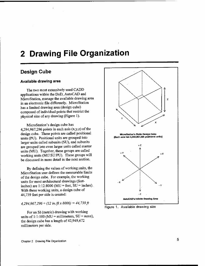
The two most extensively used CADD applications within the DoD, AutoCAD and MicroStation, manage the available drawing area in an electronic file differently. MicroStation has a limited drawing area (design cube) composed of individual points that restrict the physical size of any drawing (Figure 1).
MicroStation's design cube has 4,294,967,296 points in each axis (x,y,z) of the design cube. These points are called positional units (PU). Positional units are grouped into larger units called subunits (SU), and subunits are grouped into even larger units called master units (MU). Together, these groups are called working units (MU:SU:PU). These groups will be discussed in more detail in the next section.
By defining the values of working .units, the MicroStation user defines the measurable limits of the design cube. For example, the working units for most architectural drawings (feet- inches) are 1:12:8000 (MU = feet, SU = inches). With these working units, a design cube of 44,739 feet per side is created:
4,294,967,296 - (12 inJftx 8000) = 44,739ft
For an SI (metric) drawing with working units of 1:1:100 (MU = millimeters, SU = none), the design cube has a length of 42,949,672 millimeters per side.
MlcroStaüon's Finite Design Cube (Each axis has 4,294,967,296 positional units)
+ Z
AutoCAD's Infinite Drawing Area
Figure 1. Available drawing size
Chapter 2 Drawing File Organization
4,294,967,296 + (lmmx 100) = 42,949,672 mm
In contrast, AutoCAD's approach provides for a drawing area with infinite range in each positive and negative axis (x,y,z).
Note: The upcoming MicroStation V8 will also allow for an infinite drawing area.
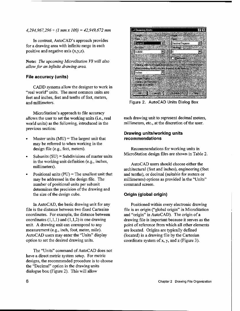
File accuracy (units)
CADD systems allow the designer to work in "real world" units. The most common units are feet and inches, feet and tenths of feet, meters, and millimeters.
f Drawing Units
[-Length.-r-^-
IRillWll |§BBH P-ccirun
jjaoooo lllllilfPiP
■
d
-Ari&e-
I Decimal Degrees B I^FiP^Ssäil! a 'CÖoeki ;wcse.
ä^^^^^^^^^lp^^SsS^^^^^^^ r Drawing units tor DeagnCanter blocks. - -.' — ■ "■—;.-.', . ■■ ' When inserting Mocks nlo'ths drawtig. scale them to..
| Inches J
c Sample Output, r—. rrr-r-z . 15000ZQ03a 00030
• ' a000(k45J)O00D ...
-5T~| Cancel | Bw" f ^~ \\
Figure 2. AutoCAD Units Dialog Box
MicroStation's approach to file accuracy allows the user to set the working units (i.e., real world units) as the following, introduced in the previous section:
• Master units (MU) = The largest unit that may be referred to when working in the design file (e.g., feet, meters).
• Subunits (SU) = Subdivisions of master units in the working unit definition (e.g., inches, millimeters).
• Positional units (PU) = The smallest unit that may be addressed in the design file. The number of positional units per subunit determines the precision of the drawing and the size of the design cube.
In AutoCAD, the basic drawing unit for any file is the distance between two fixed Cartesian coordinates. For example, the distance between coordinates (1,1,1) and (1,1,2) is one drawing unit. A drawing unit can correspond to any measurement (e.g., inch, foot, meter, mile). AutoCAD users may enter the "Units" display option to set the desired drawing units.
The "Units" command of AutoCAD does not have a direct metric system setup. For metric designs, the recommended procedure is to choose the "Decimal" option in the drawing units dialogue box (Figure 2). This will allow
each drawing unit to represent decimal meters, millimeters, etc., at the discretion of the user.
Drawing units/working units recommendations
Recommendations for working units in MicroStation design files are shown in Table 2.
AutoCAD users should choose either the architectural (feet and inches), engineering (feet and tenths), or decimal (suitable for meters or millimeters) options as provided in the "Units" command screen.
Origin (global origin)
Positioned within every electronic drawing file is an origin ("global origin" in MicroStation and "origin" in AutoCAD). The origin of a drawing file is important because it serves as the point of reference from which all other elements are located. Origins are typically defined (located) in a drawing file by the Cartesian coordinate system of x, y, and z (Figure 3).
Chapter 2 Drawing File Organization
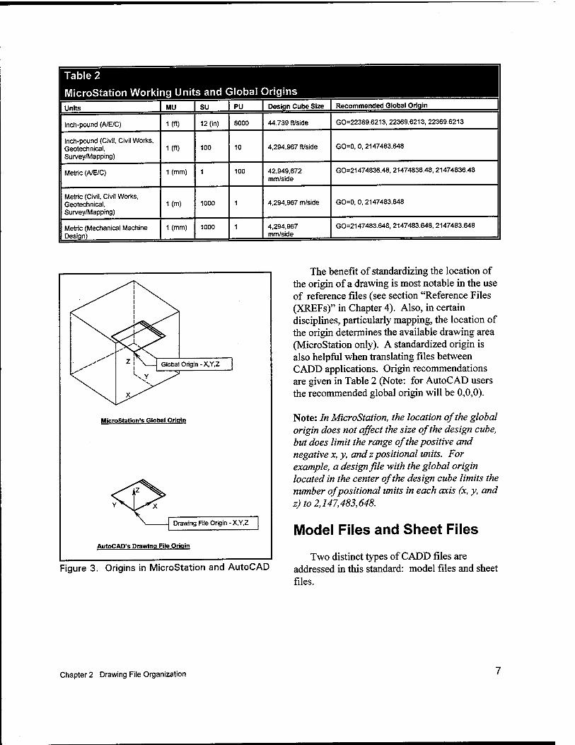
Table 2
MicroStation Working Units and Global Origins Units MU su PU Design Cube Size Recommended Global Origin
Inch-pound (A/E/C) I (ft) 12 (in) 8000 44,739 ft/Side GO=22369.6213, 22369.6213, 22369.6213
Inch-pound (Civil, Civil Works, Geotechnical, Survey/Mapping)
I (ft) 100 10 4,294,967 ft/side GO=0, 0, 2147483.648
Metric (A/E/C) 1 (mm) 1 100 42,949,672 mm/side
GO=21474836.48, 21474836.48, 21474836.48
Metric (Civil, Civil Works, Geotechnical, Survey/Mapping)
1(m) 1000 1 4,294,967 m/side GO=0, 0, 2147483.648
Metric (Mechanical Machine Design)
1 (mm) 1000 1 4,294,967 mm/side
GO=2147483.648, 2147483.648, 2147483.648
Global Origin -X.Y.Z
MicroStatlon's Global Origin
Drawing File Origin - X,Y,Z
AutoCAD's Drawing File Origin
Figure 3. Origins in MicroStation and AutoCAD
The benefit of standardizing the location of the origin of a drawing is most notable in the use of reference files (see section "Reference Files (XREFs)" in Chapter 4). Also, in certain disciplines, particularly mapping, the location of the origin determines the available drawing area (MicroStation only). A standardized origin is also helpful when translating files between CADD applications. Origin recommendations are given in Table 2 (Note: for AutoCAD users the recommended global origin will be 0,0,0).
Note: In MicroStation, the location of the global origin does not affect the size of the design cube, but does limit the range of the positive and negative x,y, and z positional units. For example, a design file with the global origin located in the center of the design cube limits the number of positional units in each axis (x, y, and z) to 2,147,483,648.
Model Files and Sheet Files
Two distinct types of CADD files are addressed in this standard: model files and sheet files.
Chapter 2 Drawing File Organization
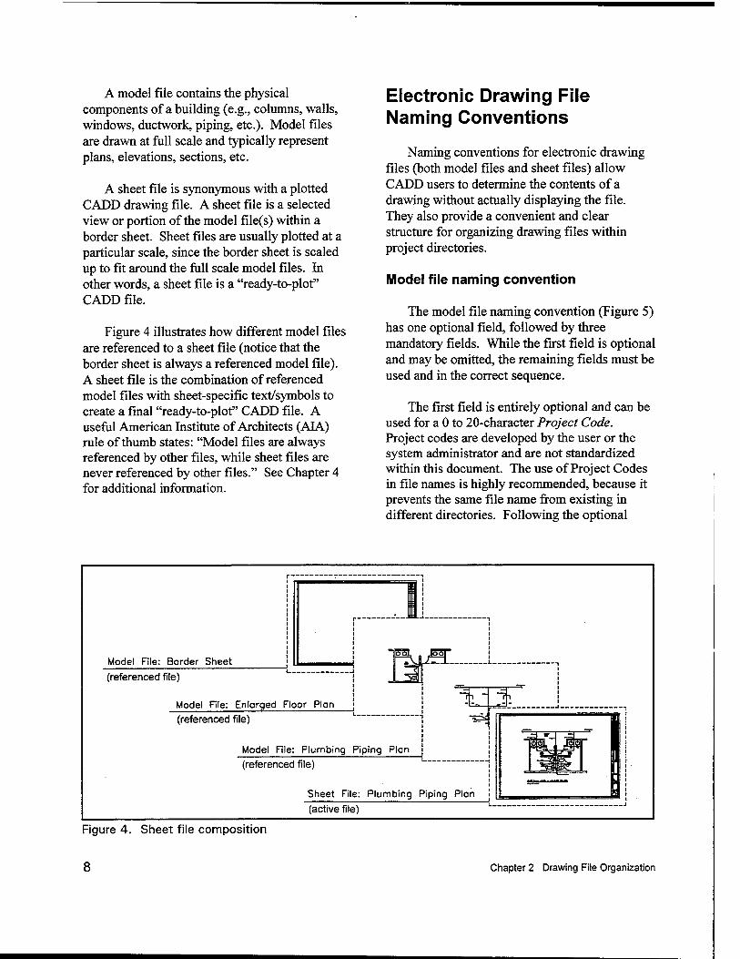
A model file contains the physical components of a building (e.g., columns, walls, windows, ductwork, piping, etc.). Model files are drawn at full scale and typically represent plans, elevations, sections, etc.
A sheet file is synonymous with a plotted CADD drawing file. A sheet file is a selected view or portion of the model file(s) within a border sheet. Sheet files are usually plotted at a particular scale, since the border sheet is scaled up to fit around the full scale model files. In other words, a sheet file is a "ready-to-plot" CADD file.
Figure 4 illustrates how different model files are referenced to a sheet file (notice that the border sheet is always a referenced model file). A sheet file is the combination of referenced model files with sheet-specific text/symbols to create a final "ready-to-plot" CADD file. A useful American Institute of Architects (ALA.) rule of thumb states: "Model files are always referenced by other files, while sheet files are never referenced by other files." See Chapter 4 for additional information.
Electronic Drawing File Naming Conventions
Naming conventions for electronic drawing files (both model files and sheet files) allow CADD users to determine the contents of a drawing without actually displaying the file. They also provide a convenient and clear structure for organizing drawing files within project directories.
Model file naming convention
The model file naming convention (Figure 5) has one optional field, followed by three mandatory fields. While the first field is optional and may be omitted, the remaining fields must be used and in the correct sequence.
The first field is entirely optional and can be used for a 0 to 20-character Project Code. Project codes are developed by the user or the system administrator and are not standardized within this document. The use of Project Codes in file names is highly recommended, because it prevents the same file name from existing in different directories. Following the optional
Model File: Border Sheet
(referenced file)
Model File: Enlorged Floor Plon
(referenced file)
Model File: Plumbing Piping Plan
(referenced file)
Sheet File: Plumbing Piping Plan
(active file)
Figure 4. Sheet file composition
8 Chapter 2 Drawing File Organization
n
- 0-20 character Project Code
- Discipline Designator
- Model File Type
II I A-FPxxxx. dwg/dgn
Figure 5. Model file naming convention
User Definable
Project Code, the first two-character field represents the Discipline Designator. The allowable characters for the first character in the Discipline Designator are listed in Table 3. The second character of the Discipline Designator field is always a hyphen "-". The next two- character field represents the Model File Type (Table 4). The final four-character field is user- definable.
Note: If the Workspace and Checker are being implemented, all eight of the mandatory characters in the model file name must be used and in the correct sequence. If all of the User Definable characters are not needed, placeholders must be used for the Workspace to function properly.
Example: The model file name for a project at Engineer Research and Development Center (ERDC), Building 8000, 1st floor, Architectural Floor Plan could be:
ERDC8000A-FPFlXX.dgn/dwg
where ERDC8000 is the Project Code, A- is the Discipline Designator, FP is the Model File Type (Floor Plan), and Fl is a user-definable set of characters for Floor 1. Since all the user definable characters were not used, the characters XX were used as placeholders.
Table 3
Discipline Designators
Discipline Designator
General G
Hazardous Materials H
Survey/Mapping V
Geotechnical B
Civil Works W
Civil C
Landscape L
Structural S
Architectural A
Interiors 1
Equipment Q
Fire Protection F
Plumbing P
Process D
Mechanical M
Electrical E
Telecommunications T
Resource R
Other Disciplines X
Contractor/Shop Drawings z 1 Operations =_____-_- o
Existing/Demolition model file naming. There are instances when a facility is being renovated and the as-built designs need to be revised to show demolition and new items.
Chapter 2 Drawing File Organization
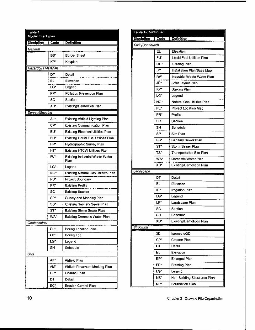
Table 4 Model File Types
Discipline | Code | Definition
General
BS* Border Sheet
KP* Keyplan
Hazardous Materials
DT Detail
EL Elevation
LG* Legend
pp. Pollution Prevention Plan
SC Section
XD* Existing/Demolition Plan
Survey/Mapping
AL* Existing Airfield Lighting Plan
CP* Existing Communication Plan
EU* Existing Electrical Utilities Plan
FU* Existing Liquid Fuel Utilities Plan
HP* Hydrographie Survey Plan
HT* Existing HTCW Utilities Plan
IW* Existing Industrial Waste Water Plan
LG* Legend
NG* Existing Natural Gas Utilities Plan
PB* Project Boundary
PR* Existing Profile
SC Existing Section
SP* Survey and Mapping Plan
SS* Existing Sanitary Sewer Plan
ST* Existing Storm Sewer Plan
WA* Existing Domestic Water Plan
Geotechnical
BL* Boring Location Plan
LB* Boring Log
LG* Legend
SH Schedule
Civil
AF* Airfield Plan
AM* Airfield Pavement Marking Plan
CP* Channel Plan
DT Detail
EC* Erosion Control Plan
Table 4 (Continued)
Discipline | Code | Definition
Civil (Continued)
EL Elevation
FU* Liquid Fuel Utilities Plan
GP* Grading Plan
IP* Installation Plan/Base Map
IW* Industrial Waste Water Plan
JP* Joint Layout Plan
KP* Staking Plan
LG* Legend
NG* Natural Gas Utilities Plan
PL* Project Location Map
PR* Profile
SC Section
SH Schedule
SP Site Plan
SS* Sanitary Sewer Plan
ST* Storm Sewer Plan
TS* Transportation Site Plan
WA* Domestic Water Plan
XD* Existing/Demolition Plan
Landscape
DT Detail
EL Elevation
IP* Irrigation Plan
LG* Legend
LP* Landscape Plan
SC Section
SH Schedule
XD* Existing/Demolition Plan
Structural
3D lsometric/3D
CP* Column Plan
DT Detail
EL Elevation
EP* Enlarged Plan
FP* Framing Plan
LG* Legend
NB* Non-Building Structures Plan
NP* Foundation Plan
10 Chapter 2 Drawing File Organization
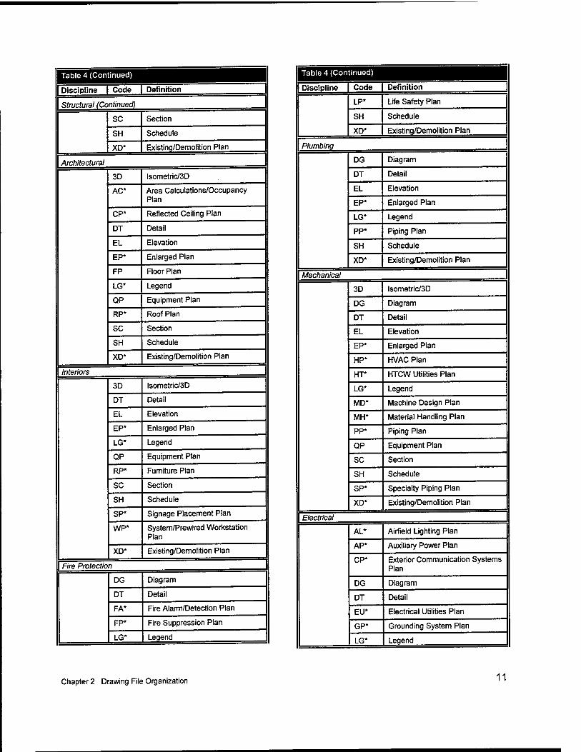
Table 4 (Continued) j
Discipline | Code | Definition
Structural (Continued)
SC Section
SH Schedule
XD* Existing/Demolition Plan
Architectural
3D lsometric/3D
AC* Area Calculations/Occupancy Plan
CP* Reflected Ceiling Plan
DT Detail
EL Elevation
EP* Enlarged Plan
FP Floor Plan
LG* Legend
QP Equipment Plan
RP* Roof Plan
SC Section
SH Schedule
XD* Existing/Demolition Plan
Interiors
3D lsometric/3D
DT Detail
EL Elevation
EP* Enlarged Plan
LG* Legend
QP Equipment Plan
RP* Furniture Plan
SC Section
SH Schedule
SP* Signage Placement Plan
WP* System/Prewired Workstation Plan
XD* Existing/Demolition Plan
Fire Protection
DG Diagram
DT Detail
FA* Fire Alarm/Detection Plan
FP* Fire Suppression Plan
LG* Legend
1 Table 4 (Continued)
Discipline Code Definition
LP* Life Safety Plan
SH Schedule
XD* Existing/Demolition Plan
Plumbing
DG Diagram
DT Detail
EL Elevation
EP* Enlarged Plan
LG* Legend
pp. Piping Plan
SH Schedule
XD* Existing/Demolition Plan
Mechanical
3D lsometric/3D
DG Diagram
DT Detail
EL Elevation
EP* Enlarged Plan
HP* HVAC Plan
HT* HTCW Utilities Plan
LG* Legend
MD* Machine Design Plan
MH* Material Handling Plan
pp. Piping Plan
QP Equipment Plan
SC Section
SH Schedule
SP* Specialty Piping Plan
XD* Existing/Demolition Plan
Electrical
AL* Airfield Lighting Plan
AP* Auxiliary Power Plan
CP* Exterior Communication Systems Plan
DG Diagram
DT Detail
EU* Electrical Utilities Plan
GP* Grounding System Plan
LG* Legend
Chapter 2 Drawing File Organization 11
Table 4 (Concluded)
Discipline | Code | Definition
Electrical (Continued)
LP* Lighting Plan
pp. Power Plan
SH Schedule
SS* Special Systems Plan
XD* Existing/Demolition Plan
Telecommunications
DG Diagram
DT Detail
LG* Legend
SH Schedule
TP* Telephone/Data Plan
XD* Existing/Demolition Plan
* = Not in NCS 2.0
These revisions would not be made on existing as-built model files, but on copies to ensure the original as-builts are not modified.
A new model file type, Existing/Demolition (XD*, where * means this type is not in NCS 2.0), has been added to the standard to allow users to make revisions to as-built files. This model file type is used to aid users in separating existing to remain items from items that will be demolished (for more information on the demolition levels/layers, see Chapter 4, "Demolition levels/layers").
Example: An Architect has an existing as- built Floor Plan model file for Building 1000, 2nd floor. For the current project, walls will be demolished and new walls constructed on the 2nd
floor. First, a copy would be made of the original as-built file (B1000A- FPF2XX.dgn/dwg) , which would be renamed to B1000RENA-XDF2XX.dgn/dwg (B1000REN is the Project Code, A- is the Discipline Designator, XD is the Model File Type (Existing/Demolition), and F2XX are user definable characters (F2=Floor 2)). The architect would open this file and move all demolition items to the first demolition
level/layer at that level/layer's correct symbology (if phased demolition is involved, the other levels/layers would be used). When the new items are drawn, the architect would open a new model file called something like
B 1000RENA-FPF2XX.dgn/dwg
(B1000REN is the Project Code, A- is the Discipline Designator, FP is the Model File Type (Floor Plan), and F2XX are user definable characters (F2=Floor 2)). The file
B1000RENA-XDF2XX.dgn/dwg
would be referenced in with the Demolition levels/layers turned off. The architect would then use the Floor Plan active levels/layers to construct the new items for that project.
Sheet file naming convention
The sheet file naming convention (Figure 6) has one optional field, followed by four mandatory fields. Similar to the format for model file naming, the first field is optional, while the remaining fields must be used and in the correct sequence.
The first field is entirely optional and can be used for a 0 to 20-character Project Code (see "Model File naming convention"). The next two characters are the Discipline Designator with Level 2 Designator (see Table 5). The next character is the Sheet Type Designator (see Table 6) followed by a two-character Sheet Sequence Number (01-99). The remaining three characters are user-definable.
12 Chapter 2 Drawing File Organization
Table 5 Discipline Designators with Level 2 Designators Discipline 1 Designator | Description Content
General —
G- All General All or any portion of subjects in the following Level 2 Designators
Gl General Informational Drawing index, code summary, symbol legend, orientation maps
GC General Contractual Phasing, schedules, contractor staging areas, fencing, haul routes, erosion control, temporary and special requirements
GR General Resource Photographs, soil borings
Hamrdaus Materials
H- All Hazardous Materials All or any portion of subjects in the following Level 2 Designators
HA Asbestos Asbestos abatement, identification, or containment
HC Chemicals Toxic chemicals handling, removal or storage
HL Lead Lead piping or paint removal
HP PCB PCB containment and removal
HR Refrigerants Ozone depleting refrigerants
Survey/Mapping
V- All Survey/Mapping All or any portion of subjects in the following Level 2 Designators
VA Aerial Survey
VF Field Survey
VH* Hydrographie Survey
VI Digital Survey
VU Combined Utilities
Gentechnical
B- All Geotechnical
Civil Works
W- All Civil Works
Civil
C- All Civil All or any portion of subjects in the following Level 2 Designators
CD Civil Demolition Structure removal and site clearing
CS Civil Site Plats, dimension control
CG Civil Grading Excavation, grading , drainage, erosion control
CP Civil Paving Roads, driveways, parking lots
Cl Civil Improvements Pavers, flagstone, exterior tile, furnishings, retaining walls, and water features
CT Civil Transportation Waterways, wharves, docks, trams, railways, airfields, and people movers
CU Civil Utilities Water, sanitary sewer, storm sewer, power, communications, fiber optic, telephone, cable television, natural gas, and steam systems |
Chapter 2 Drawing File Organization 13
Table 5 (Continued)
Discipline Designator Description Content
Landscape
L- All Landscape All or any portion of subjects in the following Level 2 Designators
LD Landscape Demolition Protection and removal of existing landscaping
LI Landscape Irrigation
LP Landscape Planting
Structural
S- All Structural All or any portion of subjects in the following Level 2 Designators
SD Structural Demolition Protection and removal
SS Structural Site
SB Structural Substructure Foundations, piers, slabs, and retaining walls
SF Structural Framing Floors and roofs
Architectural
A- All Architectural All or any portion of subjects in the following Level 2 Designators
AD Architectural Demolition Protection and removal
AS Architectural Site \ AE Architectural Elements General architectural
Al Architectural Interiors
AF Architectural Finishes
AG Architectural Graphics
Interiors
1- All Interiors All or any portion of subjects in the following Level 2 Designators
ID Interior Demolition
IN Interior Design
IF Interior Furnishings
IG Interior Graphics Murals and visuals
Equipment
Q- All Equipment All or any portion of subjects in the following Level 2 Designators
QA Athletic Equipment Gymnasium, exercise, aquatic, and recreational
QB Bank Equipment Vaults, teller units, ATMs, drive-through
QC Dry Cleaning Equipment Washers, dryers, ironing, and dry cleaning
QD Detention Equipment Prisons and jails
QE Educational Equipment Chalkboards, library
QF Food Service Equipment Kitchen, bar, service, storage, and processing
QH Hospital Equipment Medical, exam, and treatment
QL Laboratory Equipment Science labs, Planetariums, observatories
QM Maintenance Equipment Housekeeping, window washing, and vehicle servicing
OP Parking Lot Equipment Gates ticket and card access
14 Chapter 2 Drawing File Organization
Table 5 (Continued)
Discipline Designator Description Content
Equipment (Continued)
QR Retail Equipment Display, vending, and cash register
QS Site Equipment Bicycle racks, benches, playgrounds
QT Theatrical Equipment Staqe, movie, rigging systems
QV Video/Photographic Equipment
Television, darkroom, and studio
QY Security Equipment Access control and monitoring, surveillance
Fire Protection
F- All Fire Protection All or any portion of subjects in the following Level 2 Designators
FA Fire Detection and Alarm
FX Fire Suppression Fire extinguishing systems and equipment
Plumbing
P- All Plumbing All or any portion of subjects in the following Level 2 Designators
PD Plumbing Demolition Protection, termination, and removal
PS Plumbing Site Extensions and connections to Civil Utilities
PP Plumbing Piping Piping, valves, and insulation
PQ Plumbing Equipment Pumps and tanks
Process
D- All Process All or any portion of subjects in the following Level 2 Designators
DD Process Demolition Protection, termination, and removal
DS Process Site Extension and connection to civil utilities
DL Process Liquids Liquid process systems
DG Process Gases Gaseous process systems
DP Process Piping Piping, valves, insulation, tanks pumps, etc.
DQ Process Equipment Systems and equipment for thermal, electrical, materials handling, assembly and manufacturing, nuclear, power generation, chemical, refrigeration, and industrial processes
DE Process Electrical Electrical exclusively associated with a process and not the facility
DI Process Instrumentation Instrumentation, measurement, recorders, devices and controllers (electrical and mechanical)
Mechanical
M- All Mechanical All or any portion of subjects in the following Level 2 Designators
MD Mechanical Demolition Protection, termination, and removal
MS Mechanical Site Utility tunnels and piping between facilities
MH Mechanical HVAC Ductwork, air devices, and equipment
MP Mechanical Piping Chilled and heated water, steam
Ml Mechanical Instrumentation
Instrumentation and controls
Chapter 2 Drawing File Organization 15
Table 5 (Concluded)
Discipline Designator Description Content
Electrical
E- All Electrical All or any portion of subjects in the following Level 2 Designators
EA* Electrical Airfield Lighting and Navaids
Visual air navigation systems
ED Electrical Demolition Protection, termination, and removal
ES Electrical Site Exterior electrical systems (power, lighting, telecommunications, auxiliary)
EP Electrical Interior Power Interior power
EL Electrical Interior Lighting Interior lighting
El Electrical Instrumentation Controls, relays, instrumentation, and measurement devices
ET Electrical Interior Telecommunications
Interior telecommunications (telephone, network, voice and data cables)
EY Electrical Interior Auxiliary Systems
Interior auxiliary (alarms, nurse call, security, CCTV, PA, music, clock, and program)
Telecommunications
T- All Telecommunications All or any portion of subjects in the following Level 2 Designators
TD* Telecommunications Demolition
Protection, termination, and removal
TN Data Networks Network cabling and equipment
TT Telephone Telephone systems, wiring, and equipment
Resource
R- All Resource All or any portion of subjects in the following Level 2 Designators
RC Resource Civil Surveyor's information and existing civil drawings
RS Resource Structural Existing facility structural drawings
RA Resource Architectural Existing facility architectural drawings
RM Resource Mechanical Existing facility mechanical drawings
RE Resource Electrical Existing facility electrical drawings
Other Disciplines X
Contractor/Shop Drawings Z
Operations 0
* = Not in NCS 2.0 _
16 Chapter 2 Drawing File Organization
n
0-20 character Project Code
Discipline Designator w/Level 2 Designator
Sheet Type Designator
Sheet Sequence Number
n * A D 1 0 2 x x x . dwg/dgn
User Definable
Figure 6. Sheet file naming convention
Table 6 Sheet Type Designators
Sheet Type Designator
General (symbols legend, notes, etc.)
0
Plans (horizontal views) 1
Elevations (vertical views) 2
Sections (sectional views) 3
Large Scale Views (plans, elevations, or sections that are not details)
4
Details 5
Schedules and Diagrams 6
User Defined 7
User Defined 8
3D Representations (isometrics, perspectives, photographs)
9
Note: If the sheet sequence number goes above 99 sheets for a particular discipline, the first character in the User Definable field could be used to expand the limit of sheets per discipline to 999. However, if more than 99 sheets are required for one discipline's drawings, the user might want to consider using the Level 2 Designator in the Discipline Designator to further subdivide the discipline (see Table 5).
Note: Occasionally, more than one Sheet Type (e.g., plan, elevation, detail) will be represented in one sheet file. If this is the case, the dominant sheet type determines the Sheet Type Designator.
Example: The sheet file name for a project at ERDC, Building 8000,1st floor, Quadrant B, Architectural Floor Plan, sheet sequence 02 could be:
ERDC8000A-102F1B .dgn/dwg
where ERDC8000 is the Project Code, A- is the Discipline Designator, 1 is the Sheet Type Designator (Plan), 02 is the Sheet Sequence Number, and FIB is a user-definable set of characters for Floor 1, Quadrant B.
Coordination Between Sheet File Name and Sheet Identifier
In assigning a sheet identifier (for use in the sheet identification block, reference bubbles, etc.), the user should coordinate with the name assigned to the electronic sheet file. The sheet identifier should consist of the discipline designator, sheet type designator, and the sheet sequence number (Figure 7).
Chapter 2 Drawing File Organization 17
Figure 7. Typical border sheet title block with sheet identification block
As far as the sequence of the discipline designators in a drawing set, the National CAD Standard mandates that the disciplines follow the order as shown in Table 3.
18 Chapter 2 Drawing File Organization
3 Graphic Concepts
Presentation Graphics
The first step in establishing an effective CADD standard is the development of a uniform approach to presentation graphics. Presentation graphics typically consist of drawing elements such as lines, arcs, shapes, text, and their attributes (line color, line width, and line style). This chapter presents brief overviews of the characteristics of presentation graphics and the philosophy used to standardize them.
Line widths
Although "monotone" line work is not contractually improper, varied line widths substantially improve readability. Most commercial CADD systems provide an extensive variety of line widths. However, for the majority of A/E/C drawings, the five line widths defined
in Table 7, with the optional 1.00 mm, 1.40 mm, and 2.00 mm lines, are considered sufficient and should not be expanded unless an appreciable improvement in drawing clarity or contrast can be realized. The following are typical usages for the line widths shown in Table 7:
Fine (0.18 mm). Fine lines should be used sparingly, mostly for poche/patterning (this line thickness typically does not reproduce well in blue-line format and/or in photocopies).
Thin (0.25 mm). Thin lines should be used for depicting dimension lines, dimension leader/witness lines, note leader lines, line terminators (arrowheads, dots, slashes), phantom lines, hidden lines, center lines, long break lines, schedule grid lines, and object lines seen at a distance.
Table 7 Comparison of Line Widths
Line Thickness
Technical Pen Designation1 mm in.
MicroStation Line Weight2 Line Weight Example
Fine 0000 0.18 0.007 wt = 0
Thin 000 0.25 0.010 wt=1
Medium 0 0.35 0.014 wt = 2
Wide 1 0.50 0.020 wt = 3
Extra Wide 2.5 0.70 0.028 wt = 5
Option 1
Option 23
3.5
n/a
1.00
1.40
0.040
0.055
wt = 7
wt=10 _|^_H
Option 33 n/a 2.00 0.079 wt=15 ^■^^■^^^■H 1 Technical pen designation derived from Rapidograph and Rotring pen sizes. 2 The weight of MicroStation lines remains constant when plotted, no matter if the design is scaled up or down. 3 Pens not standard for ink pen plotters.
Chapter 3 Graphic Concepts 19
Medium (0.35 mm). Medium lines should be used for depicting minor object lines, dimension text, text for notes/callouts, and schedule text.
Wide (0.50 mm). Wide lines should be used for major object lines, cut lines, section cutting plane lines, and titles.
Extra wide (0.70 mm). Extra wide lines should be used for minor title underlining, schedule outlines, large titles, and object lines requiring special emphasis. For very large scale details drawn at 3 in. = 1 ft-0 in. or larger, the extra wide width should be used for the object lines. Extra wide widths are also appropriate for use as an elevation grade line, building footprint, or top of grade lines on section/foundation details.
Option 1 (1.00 mm). This line weight should be used for major title underlining and separating portions of drawings.
Option 2 (1.40 mm). This line weight should be used for border sheet outlines and cover sheet line work, and as an option for the designer as required.
• Option 3 (2.00 mm). This line weight should be used for border sheet outlines and cover sheet line work and as an option for the designer as required.
Line types/styles
The line types/styles selected for this standard are listed in Table 8. Only line IDs 0, 2, 7 and 11 are included in ISO 128 (ISO 1982). The CGTC has created line style files for MicroStation and AutoCAD (called tsaec.rsc and tsaec.lin, respectively) which include the line styles in Table 9, as well as additional discipline line styles. Appendix D contains additional line styles utilized in the standard. These files are available on the Release 2.0 CD, as well as on the CGTC's Internet site at tsc.wes.army.mil.
Table 8 Standard Line Types/Styles
ID Description Example MicroStation Designator AutoCAD Designator
0 Continuous 0 Continuous - 1 Dotted 1 ACADJSO07W100
2 Dashed 2 ACADJSOO2W100
3 Dashed spaced 3 ACADJSO03W100
4 Dashed dotted 4 ACADJSO10W100
6 Dashed double-dotted 6 ACADJSO12W100
10 Dashed triple-dotted ••■—■■ _1 ACADJS014W100
7 Chain 7 ACADJSO08W100
11 Chain double-dashed _i ACADJSO09W100
1 This line style is not found in the default MicroStation line style resource file.
20 Chapter 3 Graphic Concepts
Line color Screening
The primary reason to use color in CADD drawings is to improve the clarity of the drawing on a computer monitor. The variety of colors available in a CADD application depends on the capabilities of the computer monitor and its video card. Today, most systems are capable of displaying from 16 to 256 colors. Based on the limitations of monitor color display capabilities and differing CADD system plotting methods, this manual recommends that all A/E/C drawings be created using the basic colors presented in Table 9 whenever possible.
Note: The recommended colors are best viewed on a monitor with a black background.
Appendix C contains a 256-color map for the AutoCAD and MicroStation color palettes. The table maps AutoCAD's default color palette to MicroStation's default color palette. The color table is provided for those users who require more colors than the eight recommended by this standard.
Screened images are created through a pro- cess in which the density and pattern of black and white dots are varied to simulate different shades of gray. Varying the intensity of gray scales allows users to distinguish different aspects of a drawing when it is plotted. For example, an area on a site designated for demolition can be assigned a color that has been assigned a screening percentage. When plotted, the area will be shown at a lighter shade com- pared with other elements in the drawing. This will allow the contractor to immediately identify the demolition area on the drawing.
Table 10 lists colors recommended to be used for screening along with a recommended screening percentage. Using Table 10, Micro- Station users can edit a plotter driver, using a text editor, to assign a screening percentage to the specific colors (see the MicroStation user's manuals for information on working with plotter/printer drivers).
Table 9 Screen Color Comparison
Color
Color Number Ratios of RGB, %
AutoCAD MicroStation Red Green Blue
Blue 5 1 0 0 255
Gray 8 9 128 128 128
Green 3 2 0 255 0
Red 1 3 255 0 0
Yellow 2 4 255 255 0
Maqenta 6 5 255 0 255
Cyan 4 7 0 255 255
White 7 0 255 255 255
Note- Color numbers for AutoCAD and MicroStation were taken from default color tables.
Chapter 3 Graphic Concepts 21
Table 10 Screened Colors
AutoCAD MicroStation Gray Scale Ratios (RGB), percent
Color No.
Line Width mm
Line Width in.
Screen percent Color No. Line Weight
Screen percent Red Green Blue
10 0.18 0.007 10 10 0 10 230 230 230 11 0.25 0.010 10 19 1 10 230 230 230 12 0.35 0.014 10 27 2 10 230 230 230 13 0.50 0.020 10 35 3 10 230 230 230 14 0.70 0.028 10 43 5 10 230 230 230 15 1.00 0.039 10 51 7 10 230 230 230 16 1.40 0.055 10 59 10 10 230 230 230 19 2.00 0.079 10 83 15 10 230 230 230 50 0.18 0.007 20 20 0 20 204 204 204 51 0.25 0.010 20 28 1 20 204 204 204 52 0.35 0.014 20 36 2 20 204 204 204 53 0.50 0.020 20 44 3 20 204 204 204 54 0.70 0.028 20 52 5 20 204 204 204 55 1.00 0.039 20 60 7 20 204 204 204 56 1.40 0.055 20 68 10 20 204 204 204 59 2.00 0.079 20 92 15 20 204 204 204 90 0.18 0.007 30 82 0 30 179 179 179 91 0.25 0.010 30 106 1 30 179 179 179 92 0.35 0.014 30 92 2 30 179 179 179 93 0.50 0.020 30 122 3 30 179 179 179 94 0.70 0.028 30 114 5 30 179 179 179 95 1.00 0.039 30 138 7 30 179 179 179 96 1.40 0.055 30 130 10 30 179 179 179 99 2.00 0.079 30 170 15 30 179 179 179 130 0.18 0.007 40 87 0 40 153 153 153 131 0.25 0.010 40 95 1 40 153 153 153 132 0.35 0.014 40 103 2 40 153 153 153 133 0.50 0.020 40 111 3 40 153 153 153 134 0.70 0.028 40 119 5 40 153 153 153 135 1.00 0.039 40 127 7 40 153 153 153 136 1.40 0.055 40 135 10 40 153 153 153 139 2.00 0.079 40 159 15 40 153 153 153 170 0.18 0.007 50 97 0 50 128 128 128 171 0.25 0.010 50 105 1 50 128 128 128 172 0.35 0.014 50 113 2 50 128 128 128 173 0.50 0.020 50 121 3 50 128 128 128 174 0.70 0.028 50 129 5 50 128 128 128 175 1.00 0.039 50 137 7 50 128 128 128 176 1.40 0.055 50 145 10 50 128 128 128 179 2.00 0.079 50 169 15 50 128 128 128 210 0.18 0.007 50 85 0 50 128 128 128 211 0.25 0.010 50 109 1 50 128 128 128 212 0.35 0.014 50 101 2 50 128 128 128 213 0.50 0.020 50 125 3 50 128 128 128 214 0.70 0.028 50 117 5 50 128 128 T28 215 1.00 0.039 50 141 7 50 128 128 128 216 1.40 0.055 50 133 10 50 128 128 128 219 2.00 0.079 50 173 15 50 128 128 128 250 0.25 0.010 50 8 1 50 128 128 128 251 0.35 0.014 50 200 2 50 128 128 128 252 0.50 0.020 50 168 3 50 128 128 128 253 0.70 0.028 50 120 5 50 128 128 128 254 1.00 0.039 50 56 7 50 128 128 128 2S5 2 00 0 079 SO 24 15 50 128 12« 1?R
22 Chapter 3 Graphic Concepts
AutoCAD users must specify requirements for screening according to the output device used. Due to the number of output devices AutoCAD supports, users should consult the help documentation provided within AutoCAD for information on assigning recommended screening percentages.
Text styles/fonts
Contrasting text styles (or fonts) are used within a drawing to delineate types of informa- tion. In most A/E/C drawings, the five fonts shown in Table 11 should be sufficient.
• Monotext font. This font creates text char- acters that are evenly spaced. Monotext font should be used where text fields need to be aligned such as in schedules or, in some cases, title blocks. In AutoCAD, use the monotxt font and in MicroStation use Font #3.
• Proportional font. This font creates text where the characters are proportionally spaced. It is appropriate for general notes, labels, or title blocks. In AutoCAD, use the romans (Roman Simplex) font with a width factor of 0.8. In MicroStation use Font #1.
• Slanted font. A slanted font is used where text needs to be easily distinguished from other text. This font can be created in AutoCAD by using the romans font with the Obliquing Angle set to 21.8 deg to achieve the American Standard slope of 2 in 5 (68.2 deg). In MicroStation use Font #23.
• Filled font. Filled fonts are used primarily for titles and on cover sheets. For AutoCAD, the recommended font is the swiss TrueType font (Note: The TEXTFILL system variable needs to be set to "1" ). MicroStation users should use Font #43 (the Microsoft arialbd.ttf font file can be used as an alternate text style for the filled font).
• Outline font. When a pen plotter is used for final output, the outline font is used as a substitute for filled fonts for major titles such as cover sheet information to save plotting time. For AutoCAD, the recommended font is the sasb (Sans Serif- bold) PostScript font. For MicroStation, use Font #42.
Plotting
Printers and plotters are controlled by files called pen tables or feature tables. These files (tables) convert thicknesses and/or color in an electronic file to line thicknesses on a paper drawing.
This manual standardizes presentation graphics as they relate to electronic drawing files (screen display) and not the final printed or plotted paper drawing. By employing pen tables, each agency can ensure that consistent drawings are produced from an electronic file regardless of the type of printer or plotter used. It is the responsibility of each field activity to develop pen tables based on the printer/plotter used at that activity.
Border Sheets
Sheet sizes
Typical A/E/C projects (contract docu- ments) will be prepared on Al sheets in accord- ance with the ISO sheet size shown in Table 12, which also shows American National Standards Institute (ANSI) equivalents (American Society of Mechanical Engineers (ASME) Y14.1 (1995)).
The ISO A0 sheet is recommended for large maps (i.e., installation master plans and drawings for civil works projects).
Chapter 3 Graphic Concepts 23
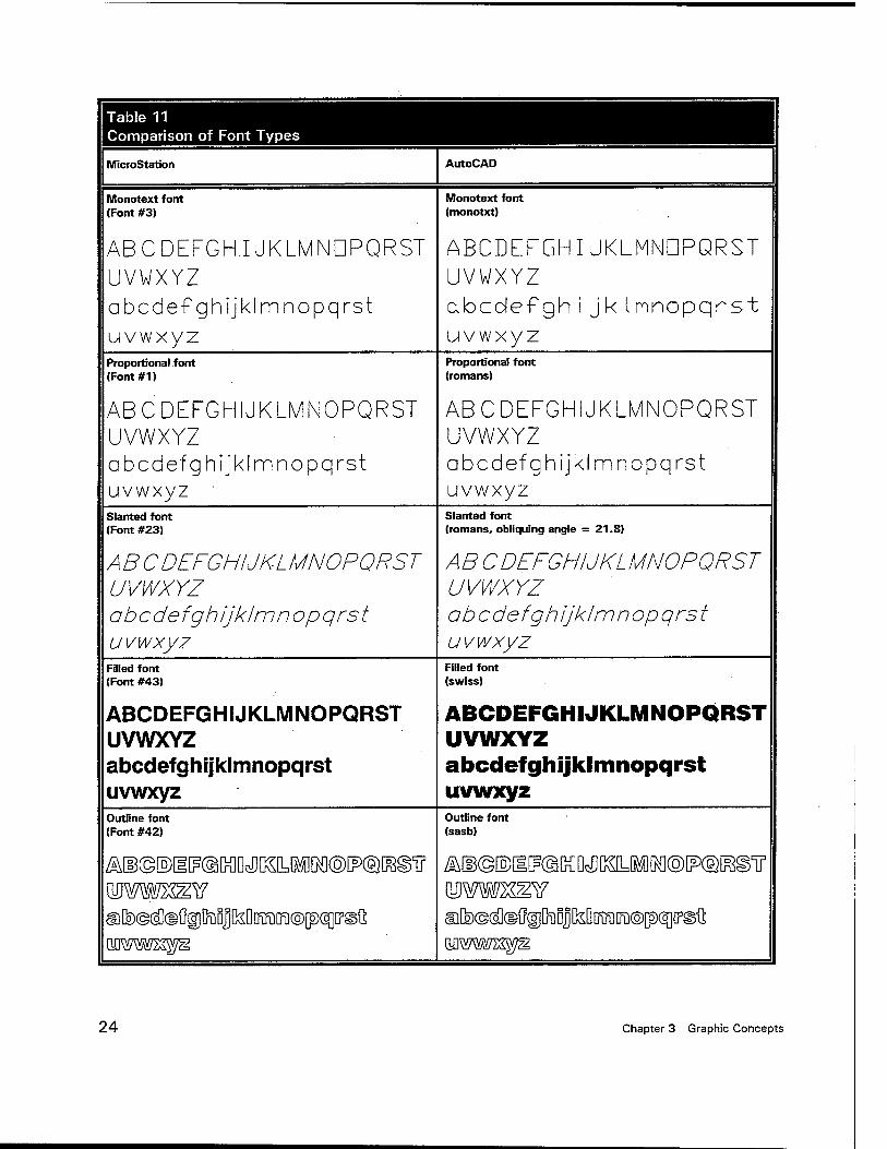
Table 11 Comparison of Font Types
MicroStation AutoCAD
Monotext font (Font #3)
Monotext font (monotxt)
ABCDEFGHUKLMNDPQRST ABCDEFGHIJKLMNDPQRST UVWXYZ UVWXYZ abcdefghijklmnopqrst abcolef gh i jk Innopqrst uvwxyz uvwxyz Proportional font (Font#1)
Proportional font (romans)
ABCDEFGHIJKLMNOPQRST ABCDEFGHIJKLMNOPQRST UVWXYZ UVWXYZ abcdefghijklmnopqrst abcdefghijklmnopqrst uvwxyz uvwxyz Slanted font (Font #23)
Slanted font (romans, obliquing angle = 21.8)
ABC DEFGHIJKL MNOPQRS T ABCDEFGHIJKLMNOPQRST UVWXYZ UVWXYZ obcdefgh Ijklm n op qrs t ab c de fgh ijklm nopqrst uvwxyz uvwxyz
Filled font (Font #43)
Filled font (swiss)
ABCDEFGHIJKLMNOPQRST ABCDEFGHIJKLMNOPQRST UVWXYZ UVWXYZ abcdefghijklmnopqrst abcdefghijklmnopqrst uvwxyz uvwxyz Outline font (Font #42)
Outline font (sasb)
^©©©i^tODcDDSLlMM®^©^©!! ^©©[©[I^MD^KLIIM©^©^©^ wmsz^a wmm^s afecg^^gjfeoJfeDDiraffQO^^D3^ ©[^©(äld^DiiDjfeDoffiiraofpqiPgG wwwzzyz wmwn^ß
24 Chapter 3 Graphic Concepts
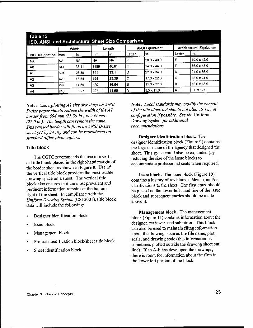
Table 12 ISO, ANSI, and Architectural Sheet Size Comparison
ISO Designation
Width Length ANSI Equivalent Architectural Equivalent
mm in. mm in. Letter in. Letter in.
NA NA NA NA NA F 28.0x40.0 F 30.0 x 42.0
AO 841 33.11 1189 46.81 E 34.0x44.0 E 36.0x48.0
A1 594 23.39 841 33.11 D 22.0 x 34.0 D 24.0 x 36.0
A2 420 16.54 594 23.39 C 17.0x22.0 C 18.0x24.0
A3 297 11.69 420 16.54 B 11.0x17.0 B 12.0x18.0
A4 210 8.27 297 11.69 A 8.5x11.0 A 9.0x12.0
Note: Users plotting Al size drawings on ANSI D-size paper should reduce the width of the Al border from 594 mm (23.39 in.) to 559 mm (22.0 in.). The length can remain the same. This revised border will fit on an ANSI D-size sheet (22 by 34 in.) and can be reproduced on standard office photocopiers.
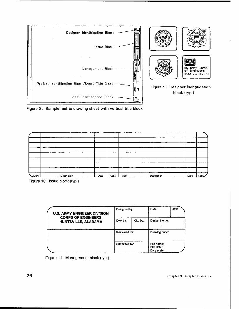
Title block
The CGTC recommends the use of a verti- cal title block placed in the right-hand margin of the border sheet as shown in Figure 8. Use of the vertical title block provides the most usable drawing space on a sheet. The vertical title block also ensures that the most prevalent and pertinent information remains at the bottom right of the sheet. In compliance with the Uniform Drawing System (CSI2001), title block data will include the following:
Designer identification block
Issue block
Management block
Project identification block/sheet title block
Sheet identification block
Note: Local standards may modify the content of the title block but should not alter its size or configuration if possible. See the Uniform Drawing System for additional recommendations.
Designer identification block. The designer identification block (Figure 9) contains the logo or name of the agency that designed the sheet. This space could also be expanded (by reducing the size of the issue block) to accommodate professional seals when required.
Issue block. The issue block (Figure 10) contains a history of revisions, addenda, and/or clarifications to the sheet. The first entry should be placed on the lower left-hand line of the issue block and subsequent entries should be made above it.
Management block. The management block (Figure 11) contains information about the designer, reviewer, and submitter. This block can also be used to maintain filing information about the drawing, such as the file name, plot scale, and drawing code (this information is sometimes plotted outside the drawing sheet cut line). If an A-E has developed the drawings, there is room for information about the firm in the lower left portion of the block.
Chapter 3 Graphic Concepts 25
Designer Identification Block
Issue Block
Management Block
Project Identification Block/Sheet Title Block
Sheet Identification Block
ra US Army Corps of Engineers Division or District
Figure 9. Designer identification block (typ.)
Figure 8. Sample metric drawing sheet with vertical title block
c \
VlWark DescriDtion Date ., Aoor.,. Mark Desertion Datp _ABBI>/
Figure 10. Issue block (typ.)
U.S. ARMY ENGINEER DIVISION CORPS OF ENGINEERS HUNTSVILLE, ALABAMA
Designed by: Date: Rev:^\
Dwnby: Ckd by: Design file no.
V
Reviewed by: Drawing code:
Submitted by: File name: Plot date: Dwg scale: )
Figure 11. Management block (typ.)
26 Chapter 3 Graphic Concepts
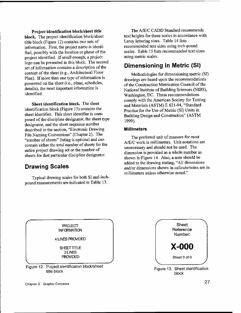
Project identification block/sheet title block. The project identification block/sheet title block (Figure 12) contains two sets of information. First, the project name is identi- fied, possibly with the location or phase of the project identified. If small enough, a project logo can be presented in this block. The second set of information contains a description of the content of the sheet (e.g., Architectural Floor Plan). If more than one type of information is presented on the sheet (i.e., plans, schedules, details), the most important information is identified.
Sheet identification block. The sheet identification block (Figure 13) contains the sheet identifier. This sheet identifier is com- posed of the discipline designator, the sheet type designator, and the sheet sequence number described in the section, "Electronic Drawing File Naming Conventions" (Chapter 2). The "number of sheets" listing is optional and can contain either the total number of sheets for the entire project drawing set or the number of sheets for that particular discipline designator.
Drawing Scales
Typical drawing scales for both SI and inch- pound measurements are indicated in Table 13.
The A/E/C CADD Standard recommends text heights for these scales in accordance with Leroy lettering sizes. Table 14 lists recommended text sizes using inch-pound scales. Table 15 lists recommended text sizes using metric scales.
Dimensioning in Metric (SI) Methodologies for dimensioning metric (SI)
drawings are based upon the recommendations of the Construction Metrication Council of the National Institute of Building Sciences (NIBS), Washington, DC. These recommendations comply with the American Society for Testing and Materials (ASTM) E 621-94, "Standard Practice for the Use of Metric (SI) Units in Building Design and Construction" (ASTM 1999).
Millimeters
The preferred unit of measure for most A/E/C work is millimeters. Unit notations are unnecessary and should not be used. The dimension is provided as a whole number as shown in Figure 14. Also, a note should be added to the drawing stating, "All dimensions and/or dimensions shown in callouts/notes are in millimeters unless otherwise noted."
PROJECT INFORMATION
4 UNES PROVIDED
SHEET TITLE 3 LINES
PROVIDED
Figure 12. Project identification block/sheet title block
Sheet Reference Number:
X-000 Sheet 0 of 0
Figure 13. Sheet identification block
Chapter 3 Graphic Concepts 27
Table 13 Drawing Scales
Drawing Type Metric Inch-Pound
Site plans 1
1
1
1
1
1
1
1
1
1
1
200
400
500
600
700
1000
2000
5000
6000
10000
20000
1
1
1
1
1
1
1
1
1
1
1
= 20' - 0"
= 30' - 0"
= 40' - 0"
= 50' - 0"
= 60' - 0"
= 100'-0"
= 200' - 0"
= 400' - 0"
= 500' - 0"
= 1000'-0"
= 2000' - 0"
Floor plans 1
1
1
50
100
200
1/4" = 1'-0"
1/8" = 1'-0"
1/16"=1'-0"
Roof plan 1 200 1/16" = 1'-0"
Exterior elevations 1
1
100
200
1/8" = 1'-0"
1/16"=1'-0"
Interior elevations 1
1
50
100
1/4" = 1'-0"
1/8" = 1'-0"
Cross sections 1
1
1
50
100
200
1/4" = 1'-0"
1/8" = 1'- 0"
1/16"= 1'-0"
Wall sections 1 20 1/2"or3/4" = 1'-0"
Stair details 1 10 1" or 1-1/2" = 1'-0"
Details 1
1
5
10
3" = 1'-0"
1" or 1-1/2" = 1'-0"
28 Chapter 3 Graphic Concepts
o o o o o o o o o O o ■"»■ co o "* o co o o oo o o o o
o o
o o o o o r> o o o o o o r— T— CM CM ■* CO o CD CM o o o o o o o CO in •G co CM ^ o o o in •fl- CM T—
1
V- r- CM X—
O o o ea O o o o O o O CM ■a- CO co O ■* o o •■* o O o o m <-> O o o o o o o in O in O T— ■*— CM •* m CO CO
o o o o m o o u> CO CM CM T— T— » ö o in o IT) CM CM T—
ll) o
o O CD o o CO CD co O O) co r~ ■* IT) !•- o T- 00 in CO o t^. in CM
in o in CM o in CM IT) r- t- CM co >E— CO K.. T— ■<— CO ■fl-
l. . co It) CM in CM 1- oo ■fl- CM CM ^— *~ q CM •fl- •fl-
ö 00 ■fl- CM r-
o o o o o O o CO o CO o Tf oo CM CO ^a- T- in o 00 h~ CM o m CO o o o in o o in T— |-~ ■* o h- T- CM ■"«- in oo
l. . T- \. CO in T-
o in o in i^ ■fl- f~ co CM T- ■^~ T— q CO
CO
ö i^ CO ■c-
o o o o o o IT) co CO oo O CM CO in CD i^- co CM •fl- r- oo •fl o O) CM o o o in en CO CD 1^ •fl- T— oo 7". T- CM co ■<r C3) T- CM CO ■fl- O)
o <T) on O) ■fl- T— m CM r— ^— T— U) o U) CM in CM r— CM
O
(A o o o o o o in o CO CM o T- CM co oo oo r^ o ■<- CD o oo o •fl- CM o £ o o o en 00 ■fl- ■fl- CM O) 1^ ^.. CM co m i^ T— \ . CM i. r--
O ■fl- Ü or» ■fl- CM en •fl- CM T- •fl- q ■fl- CM
CM Ö
•fl- CM v-
c < o
o CM
o O o o o o o o o O o co CD ■>* CM CO ■fl- CD t^ •»- CM m n 4>
CD U_
c
en 8
o o o o o o CM o CO CO ■* o T- CM co ■* CD a> t- CM CO CO O o o o o oo •fl- CM T- r— q o CM
CM
d
m
■fl- CM r—
q O in
CD
1^
o o iri
CO 1^
CD Ö
O) CO
o 1^
CO in
CO in
i>- ö
•* CM
oo CM
CM CD in
•fl- ed
in O o ^— in in
If) f~- CO in CO
03 t~- CO T~ T_ ' Ö o X
V o •<T o o O o o o in o co CM o co ■<- t^ CM ■fl- in r~ t— co CO CO
o o o O en on ■fl- on r^ in ■* T— ^~ T- t— CM ■fl- o •q- on •fl- r-~ in CM ö T CM
o
o o o o o o CM O o t^ in m T- in CM CO ■sr CO o co O o o CM o o o O oo •fl- CM t~- CD in co CM o "t- T- T— CM
co' <-> CM
CM •fl- CM
CM CD ■fl- CM r- o \v—
O
o o O o O o o o o o o ■<r 00 CM CD •"3- co in o o h- CM o o o o o O o o o CO lO -3- CO CM o o T— t— CM
l.. T- r— CO k-> <-) o o in ■fl- CM x— o <_> T~ CM o
o o o o O o o o CM in 1^- co CO T- CO CM in •fl- CO o co CO o oo n o o o o CM CD CO Tl •fl- CO CM T— o o T— CM
l. . •«- CM
CO co o O
CD 00 ■fl- CO •fl- q
o o o o O o C~ o in o CM CM in 1^ •f- in CM co co oo o O o CO o o o o o T CM CO CO CO CM T— o o o t— T- CM
CD CD O Ö
CM CO co CM T— q
o o o o O o o o o o o o o o o o o o o o o O i
_i _i
o o o o o o o o o o o T— T— u. o o o o o o CD in •sr co CM II || II ll II II II II
^fcf Ü CM
o *r-
ID II II
CM
II II II II n II II
CO N %• CM co V en CM CO CM en II II ■<— T~ T- T- ^~ CO CO ^: CO ^7 C)
= = V" T- v ■ C) T— T— T— T- *
en 0 N
co > CO IT II II II II II II II II II II II ii II II II II ll II ll II II II II
■S ro LU fl) _a> a> CD
m CD
re CD
ro CD
CO
CD
m CD
en CD
co CD
en SSL
CO
CD
CO
CD
CO
CD
co CD
co CD
CO
CD
CO
CD
co .CD
CO
CD
CO
CD
CO CO
0> C) e) C) o e> u <> C) u c; o ^B^ c V) CO CO CO co CO CO CO CO co CO CO CO CO w to w CO CO (/J U) CO CO
Q) — n) n> n> ra n> ra n> rr> o> Ol O) O) O) O) a D) a o D) H^L. _l
£ c c c c c c c c c t: c c c c_ L.
K^^F^ O a>
i
5 ^ =! 5 *: =S =5 =S =S % 5 ? 5 S S 5 5 £ 5 $ 5 i- ^
EP= o a
CD
ä co Q
CO CO *— 1 I— Q|Q
CO
Q 5 Q
CO i— a
co Q
re Q
co co Q|Q
CO
D CO
Q co ro Q|Q D
CO v_
Q co >— Q
cu Q
eu D
U)
Q Q ö
Chapter 3 Graphic Concepts 29
o o o o o o o o o o o o o o o in in in o o o o o o o o o o o o in o m CM CM
CD
CM Ho o o o o o o in o in o o LO CM m CM T— ■o to o o o m o m t>- m CM o in CM ■o CM o m in CM in CM T- T— T— T-
in CM T— T—
o o o o o o o o o o o o o o o o O CM o o o o o o o o o o o o o "3- CM CD CO T—
lo o o o o o o ■*r CM o oo "3- CM CD CM T—
Ho CM o o CM o "3- CM CO r~- CO ■*r CM x— ■ in
T— ■<3- CM r^. CD CM r- CM r~ O o o O O o o o o o o o o o o in m T~
O o o O O o o o o o o o m CM V- in
CM
T—
Hm O o o O O o f- CD in •* CM T~ in CM T—
HCM ■x- O o CD in CM T- h- CD m ■* CM T-
■ rr r— CM T— CD in CM X—
CM ^" O o o O O o o o o o o o o o o in m CO O o o o O o o o o o o o in 00 C3> ■<3- CM
CM Blo O o o o O o CO T in CD CO en T T— ■ in CO O o ■<3- in CO co CD m •3- CO v—
:CO CO T—
CO in •"3- r—
O o o O o o o o o O o o LO o in m in in O o o O o o in o m o o in 1^- in s.
i^ co
N; r-»' Bio m O o o in o m CM m N- o in r^ co T— oo' ^■m O in in h- m N- m •* co CO T—
CM 1^ in i—
1^. ■"3- co
O o o O o o o o o o o o o o o o in CO
i2 O o o O o o o o o o o o o CM CD CO T—
Ho O o o o o o CM CD o ■<* CM CO CO T—
■ ^r CD o o o CD o CM CD ■>* CO CO CM ^— ■CM 13
E CM CD CO CO
o o o o o o o o o o o o o o o in in in
i O o o o o o o o o o o o in o in CM CM Ho O o o o o o in o m o o m CM T—
Ho in c o o o m o in CO CO CM CM T— **" ■CM
0) V 1*4
o m CO CM
55 o o o o o o o o o o o o to o m in m LO o o o o o o m o m o o in CM en f CM
CM
CM ■^ IIA in
>*-* o o o in o in ■C— h- CM 00 o> ■* CM ■ r^ X o in l*~ CM CO -3- CO CM CM T- ^
r*- ■<r 1-
O) ■* CM CM
o o o O o o o O O o o o in o in m in LO o o o O o o m O in o o in i*- r-- CO
t^ t~- CO Ho m o o o m o in •* •*— f- -3- f- CO v- oci ■ ^ o m T— 1*. r^ CO CM CM T—
co 1^ CO CM v-
o o o O o o o O o o o o O o o m in CO o o o O o o o O o o o o in CO CO T— r^ Ho o o o O o o T— CD m CM CD CO T-
■ CM co o o 00 in CD CO CM T- T— T— T— CD co T—
o o o o o o O O o o o o in o m m m in o o o o o o in o io o o in CM in CM CM CM CM Ho in o o o in o in t^- in CM o LD CM i-
CD Ho o in in CM m CM T- t— ^H-v~ CM in CM
i
o o o o o o O o o o o o o o O o m C-; o o o o o o O o o o o o o •sr CM T—
o o o o o o "» CM o 00 ■<r CM ▼— Ho CM o o CM o ■<r CM T— 1— ■03 ■3- CM
o o o o o o o o o o o o in o in m in in o o o o o o in o in o o in N- CO
i^ r^
in o o o in o in o en I-- CD CO r- CO
* Ho o in en t~- CO ■(O CO
o o o o o o o o o o o o o o o o o o o o m _i
10 o o o o o o o o o o o o o o O —i a> CM T— CD m CM T— I'- CD m -3- CM T— m CM T— in CM Z) ■Hht
CD E LL.
N
CO X o II II II n II II ll II II II ii II ll II II II II II CO c. Q. CD CD CD CD CD CD CD CD 0 CD CD CD CD CD CD CD CD CD
a. CO co ro CO CO CO CO CO CO CO CO CO co CO CO co CO CO
£ < o o o Ü O O o Ü o o u o o o o o ü o i_ CO co CO co CO CO CO CO CO co co CO W W CO (0 CO CO
_Q) CO co a> CO CO co CO CO CO CO CO CO CO CO CO CO CO CO K^H~ a> c c c c c c c c c c c c c cr c c c c ElSH^" o E 3 5 g g 5 g g g g g g g g g g g g g
i— CO CO CO CO CO CO CO co CO CO CO co CO CO CO CO CO CO CD l_ L_ h— 1» L_ 1— L- I— 1— l_ V- t—
_J 2 a a a Q a Q a a a Q o Q a Q a Q Q Q
30 Chapter 3 Graphic Concepts
350
Figure 14. Dimension in millimeters. Always shown as a whole number
When meter measurements are included on the same sheet, the meter dimension is provided as a real number taken to three places past the decimal point (Figure 15). Again, unit notations are unnecessary.
Figure 15. Dimension in meters. Always shown as a real number (with decimal)
Note: In circumstances where very small dimensions are used (e.g., machine details), it is permissible to use real numbers for millimeter dimensions. A note should be placed on the detail regarding this fact.
five or more digits (e.g., the number 45,000 is displayed as 45 000). In numbers containing four digits, no space is used (e.g., 5000). Both methods are shown in Figure 16.
5000
Four digits or less
45 000
5 digits or more "igure 16. Proper dimension presentations for
metric measurements with four or more digits
The Unit Separation toggle under the Unit Format setting for Dimension Settings can be used to add a space after the thousands place in a value (Figure 17). Since toggling this value on and off for drawing files containing varying dimension values would be tedious, recommend toggling Unit Separation "on" for files con- taining any dimension values over 5 digits and "off for files containing dimension values with only 4 or fewer digits.
Meters
For site plans or other drawings drawn to scales over 1:200, the unit of measure is typically meters. Where greater accuracy is required, show dimensions to three decimal places (Figure 15). A note should be added to the drawing stating, "All dimensions and/or dimensions shown in callouts/notes are in meters unless otherwise noted."
Large units of measure
Commas shall not be used when providing large units of measure; instead, a space replaces the traditional comma in numbers containing
Custom Symbols Dimension Lines Extension Lines Placement Terminators Terminator Symbols Text Tolerance Tool Settings Units
iFöcusjltem Description"
Angle Format
Una. Degrees
Accuacy: D123 ' pjsptay. D.DDDO
Metric Format —— T-?. I- Use&smafbrDecteal
!>[ IMlSepasstai '
W ShowLea&sgZeto
pf ShowTiafogZetos
Secondeiy 1~ Sho#Laadinfl2erq r" ShowTiainsZeros ;
Sel'Äaraon urÄjötmat-pÄarhetejsf;
Figure 17. Unit format
Chapter 3 Graphic Concepts 31
Note: The automatic dimensioning features of AutoCAD do not allow users to replace commas with spaces in dimension text. The dimension text will presently have to be edited to provide the spacing required by ASTME 621-94 (ASTM 1999).
Dual units
To avoid confusion, dual units (both inch- pound and metric) should not be used. As stated in Construction Metrication Council (1998), use
of dual units "increases dimensioning time, doubles the chance for errors, makes drawings more confusing, and only postpones the (metric) learning process."
Exceptions to this include certain "standard building designs" where dual dimensions ensure that the design can be used in either SI or inch- pound projects and in situations where products/components used in an SI project are available only as inch-pound products.
32 Chapter 3 Graphic Concepts
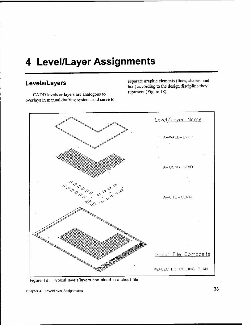
4 Level/Layer Assignments
Levels/Layers
CADD levels or layers are analogous to overlays in manual drafting systems and serve to
separate graphic elements (lines, shapes, and text) according to the design discipline they represent (Figure 18).
o
Figure 18. Typical levels/layers contained in a sheet file
Chapter 4 Level/Layer Assignments
Level/Layer Name
A-WALL-EXTR
A-CLNG-GRID
A-LITE-CLNG
Sheet File Composite
REFLECTED CEILING PLAN
33
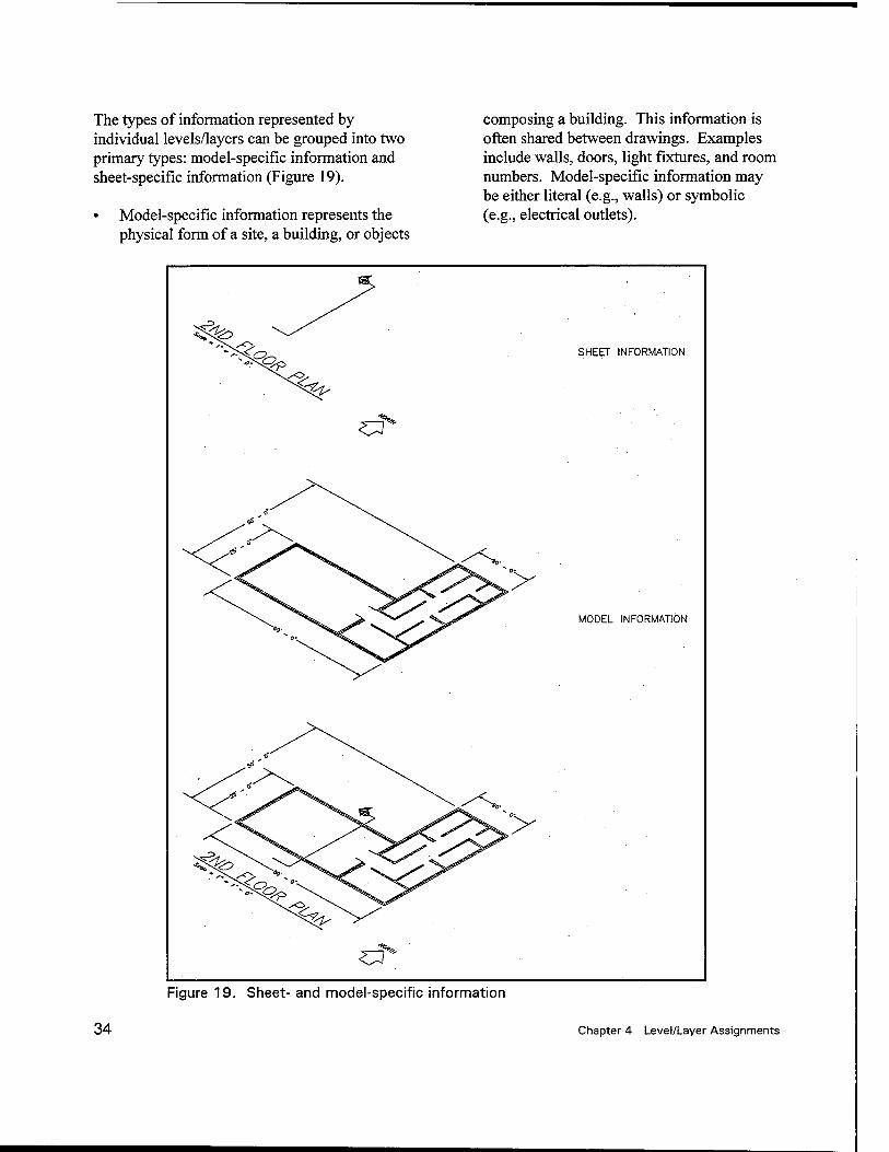
The types of information represented by individual levels/layers can be grouped into two primary types: model-specific information and sheet-specific information (Figure 19).
• Model-specific information represents the physical form of a site, a building, or objects
composing a building. This information is often shared between drawings. Examples include walls, doors, light fixtures, and room numbers. Model-specific information may be either literal (e.g., walls) or symbolic (e.g., electrical outlets).
SHEET INFORMATION
cf
MODEL INFORMATION
c3* Figure 19. Sheet- and model-specific information
34 Chapter 4 Level/Layer Assignments
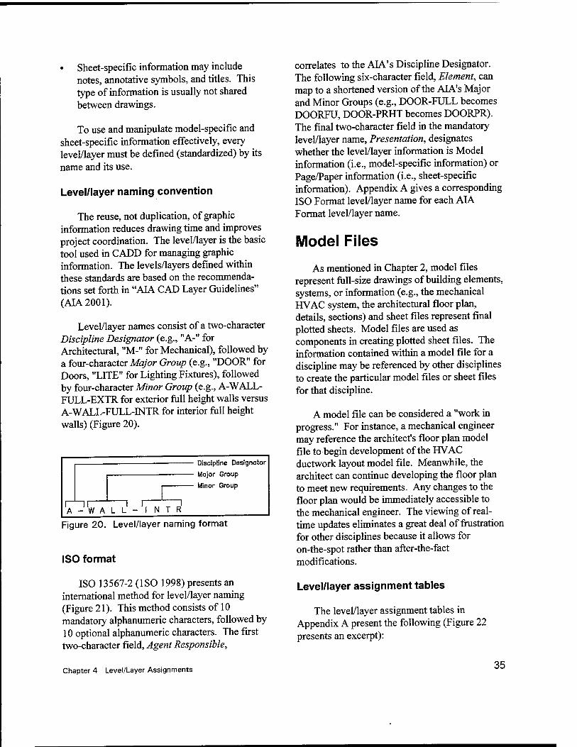
• Sheet-specific information may include notes, annotative symbols, and titles. This type of information is usually not shared between drawings.
To use and manipulate model-specific and sheet-specific information effectively, every level/layer must be defined (standardized) by its name and its use.
Level/layer naming convention
The reuse, not duplication, of graphic information reduces drawing time and improves project coordination. The level/layer is the basic tool used in CADD for managing graphic information. The levels/layers defined within these standards are based on the recommenda- tions set forth in "AIA CAD Layer Guidelines" (AIA2001).
Level/layer names consist of a two-character Discipline Designator (e.g., "A-" for Architectural, "M-" for Mechanical), followed by a four-character Major Group (e.g., "DOOR" for Doors, "LITE" for Lighting Fixtures), followed by four-character Minor Group (e.g., A-WALL- FULL-EXTR for exterior full height walls versus A-WALL-FULL-INTR for interior full height walls) (Figure 20).
~ir W A L L
i r
Discipline Designator
Mojor Group
Minor Group
I N T R
Figure 20. Level/layer naming format
ISO format
ISO 13567-2 (ISO 1998) presents an international method for level/layer naming (Figure 21). This method consists of 10 mandatory alphanumeric characters, followed by 10 optional alphanumeric characters. The first two-character field, Agent Responsible,
correlates to the AIA's Discipline Designator. The following six-character field, Element, can map to a shortened version of the AIA's Major and Minor Groups (e.g., DOOR-FULL becomes DOORFU, DOOR-PRHT becomes DOORPR). The final two-character field in the mandatory level/layer name, Presentation, designates whether the level/layer information is Model information (i.e., model-specific information) or Page/Paper information (i.e., sheet-specific information). Appendix A gives a corresponding ISO Format level/layer name for each AIA Format level/layer name.
Model Files
As mentioned in Chapter 2, model files represent full-size drawings of building elements, systems, or information (e.g., the mechanical HVAC system, the architectural floor plan, details, sections) and sheet files represent final plotted sheets. Model files are used as components in creating plotted sheet files. The information contained within a model file for a discipline may be referenced by other disciplines to create the particular model files or sheet files for that discipline.
A model file can be considered a "work in progress." For instance, a mechanical engineer may reference the architect's floor plan model file to begin development of the HVAC ductwork layout model file. Meanwhile, the architect can continue developing the floor plan to meet new requirements. Any changes to the floor plan would be immediately accessible to the mechanical engineer. The viewing of real- time updates eliminates a great deal of frustration for other disciplines because it allows for on-the-spot rather than after-the-fact modifications.
Level/layer assignment tables
The level/layer assignment tables in Appendix A present the following (Figure 22 presents an excerpt):
Chapter 4 Level/Layer Assignments 35
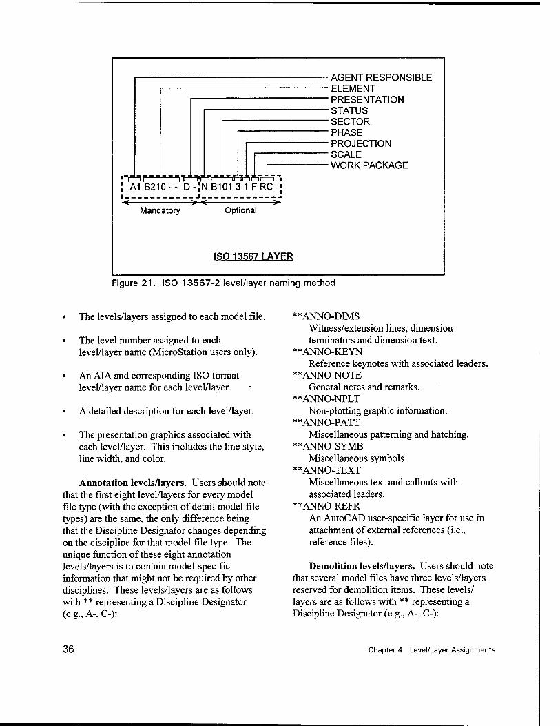
~\ r inr nnnr -\ i ! A1 B210-- D-JNB101 3 1 F RC J
Mandatory
. -i. > <
Optional
ISO 13567 LAYER
AGENT RESPONSIBLE ■ ELEMENT • PRESENTATION STATUS SECTOR PHASE PROJECTION SCALE WORK PACKAGE
Figure 21. ISO 13567-2 level/layer naming method
• The levels/layers assigned to each model file.
• The level number assigned to each level/layer name (MicroStation users only).
• An AIA and corresponding ISO format level/layer name for each level/layer.
• A detailed description for each level/layer.
• The presentation graphics associated with each level/layer. This includes the line style, line width, and color.
Annotation levels/layers. Users should note that the first eight level/layers for every model file type (with the exception of detail model file types) are the same, the only difference being that the Discipline Designator changes depending on the discipline for that model file type. The unique function of these eight annotation levels/layers is to contain model-specific information that might not be required by other disciplines. These levels/layers are as follows with ** representing a Discipline Designator (e.g., A-, C-):
**ANNO-DIMS Witness/extension lines, dimension terminators and dimension text.
**ANNO-KEYN Reference keynotes with associated leaders.
**ANNO-NOTE General notes and remarks.
**ANNO-NPLT Non-plotting graphic information.
**ANNO-PATT Miscellaneous patterning and hatching.
**ANNO-SYMB Miscellaneous symbols.
**ANNO-TEXT Miscellaneous text and callouts with associated leaders.
**ANNO-REFR An AutoCAD user-specific layer for use in attachment of external references (i.e., reference files).
Demolition levels/layers. Users should note that several model files have three levels/layers reserved for demolition items. These levels/ layers are as follows with ** representing a Discipline Designator (e.g., A-, C-):
36 Chapter 4 Level/Layer Assignments
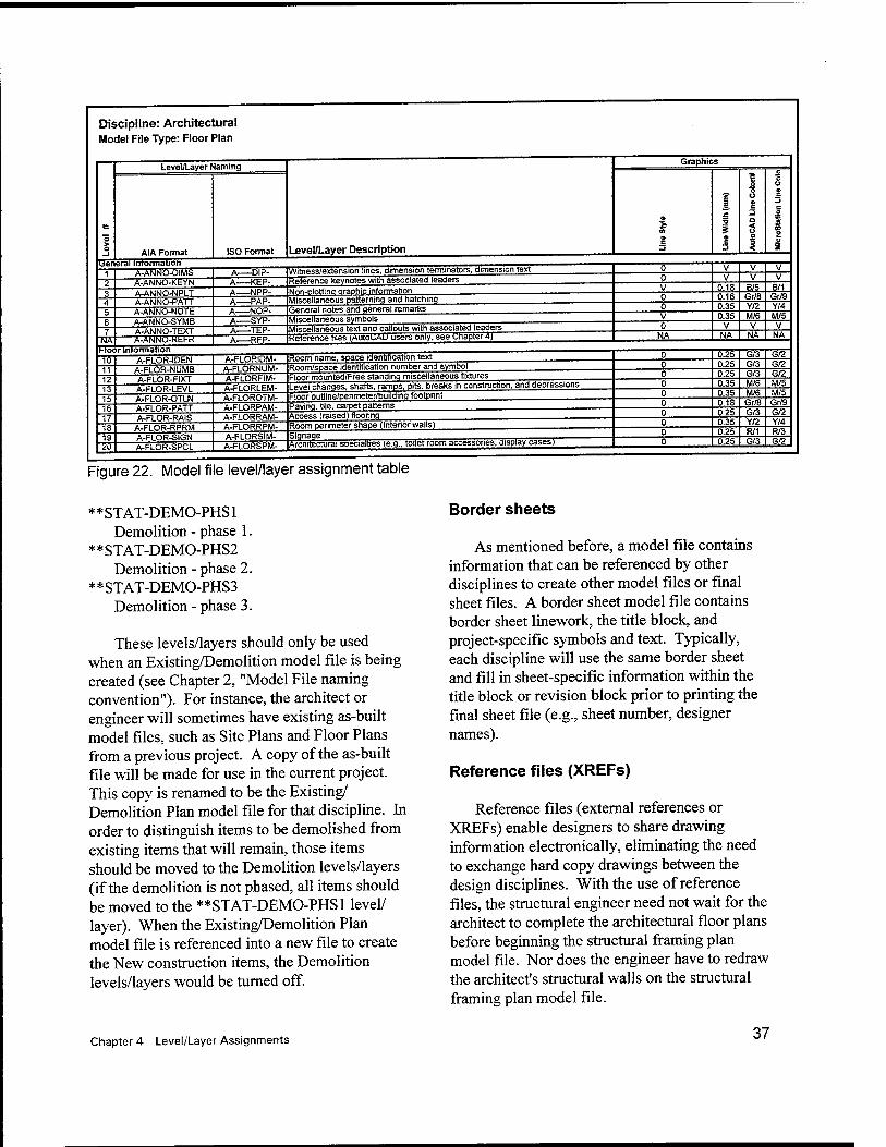
Discipline: Architectural Model File Type: Floor Plan
Level/Layer Naming
AIA Format tjen'erai intormatiöTT"
ISO Format Level/Layer Description
Graphics
A-AWo-uiUs A-ANNO-KEYN~ A-ANNO-NPLT A-ANNO-PATT A-ANNO-NOTE~ A-ANNO-SYMB A-ANNO-TEXT A-ANNO-Kbl-K NA.
Hoor mromiation
Witness/extension lines, dimension terminators, dimension text -KSP- -NPP- -PAP- -NOP-
Reference keynotes with associated leaders Non-plotting graphic information Miscellaneous patterning and hatching General notes and general remarks Miscellaneous symbols-
Miscellaneous text and callouts with associated leaders Reference tiles (AutoCAD users only, see chapter 4)
0.18 0.18 0.35 0.35
B/5 Gr/8 Y/2 M/6
To"
7U
A-FLOR-IDEN A-FLOR-NUMB A-FLOR-FIXT A-FLOR-LEVL A-FLOR-OTLN A-FLOR-PATT A-FLOR-RAIS
A-FLOR-RPRM A-FLOR-SIGN A-FLOR-SPCL
A-FLORIDM- A-FLORNUM- A-FLORFiM- A-FLORLEM- A-FLOROTM- A-FLORPAM- A-FLORRAM- A-FLORRPM- A-FLORSIM- A-FLORSPM-
Room name, space identification text Room/space identification number and symbol Floor mounted/Free standing miscellaneous fixtures Level changes, shafts, ramps, pits, breaks in construction, and depressions Floor outline/perimeterfouilding footprint Paving, tile, carpet patterns Access (raised) flooring Room perimeter shape (Interior walls) Signage Architectural specialties (e.g., toilet room accessories, display cases)-
0.25 0.25 0.35 0.35 0.18 0.25
G/3 G/3 G/3
G/3
Figure 22. Model file level/layer assignment table
**STAT-DEMO-PHSl Demolition - phase 1.
**STAT-DEMO-PHS2 Demolition - phase 2.
**STAT-DEMO-PHS3 Demolition - phase 3.
These levels/layers should only be used when an Existing/Demolition model file is being created (see Chapter 2, "Model File naming convention"). For instance, the architect or engineer will sometimes have existing as-built model files, such as Site Plans and Floor Plans from a previous project. A copy of the as-built file will be made for use in the current project. This copy is renamed to be the Existing/ Demolition Plan model file for that discipline. In order to distinguish items to be demolished from existing items that will remain, those items should be moved to the Demolition levels/layers (if the demolition is not phased, all items should be moved to the **STAT-DEMO-PHSl level/ layer). When the Existing/Demolition Plan model file is referenced into a new file to create the New construction items, the Demolition levels/layers would be turned off.
B/1 Gr/9 Y/4 M/5
G/2 G/2
Gr/9
R/3 G/2
Border sheets
As mentioned before, a model file contains information that can be referenced by other disciplines to create other model files or final sheet files. A border sheet model file contains border sheet linework, the title block, and project-specific symbols and text. Typically, each discipline will use the same border sheet and fill in sheet-specific information within the title block or revision block prior to printing the final sheet file (e.g., sheet number, designer names).
Reference files (XREFs)
Reference files (external references or XREFs) enable designers to share drawing information electronically, eliminating the need to exchange hard copy drawings between the design disciplines. With the use of reference files, the structural engineer need not wait for the architect to complete the architectural floor plans before beginning the structural framing plan model file. Nor does the engineer have to redraw the architect's structural walls on the structural framing plan model file.
Chapter 4 Level/Layer Assignments 37
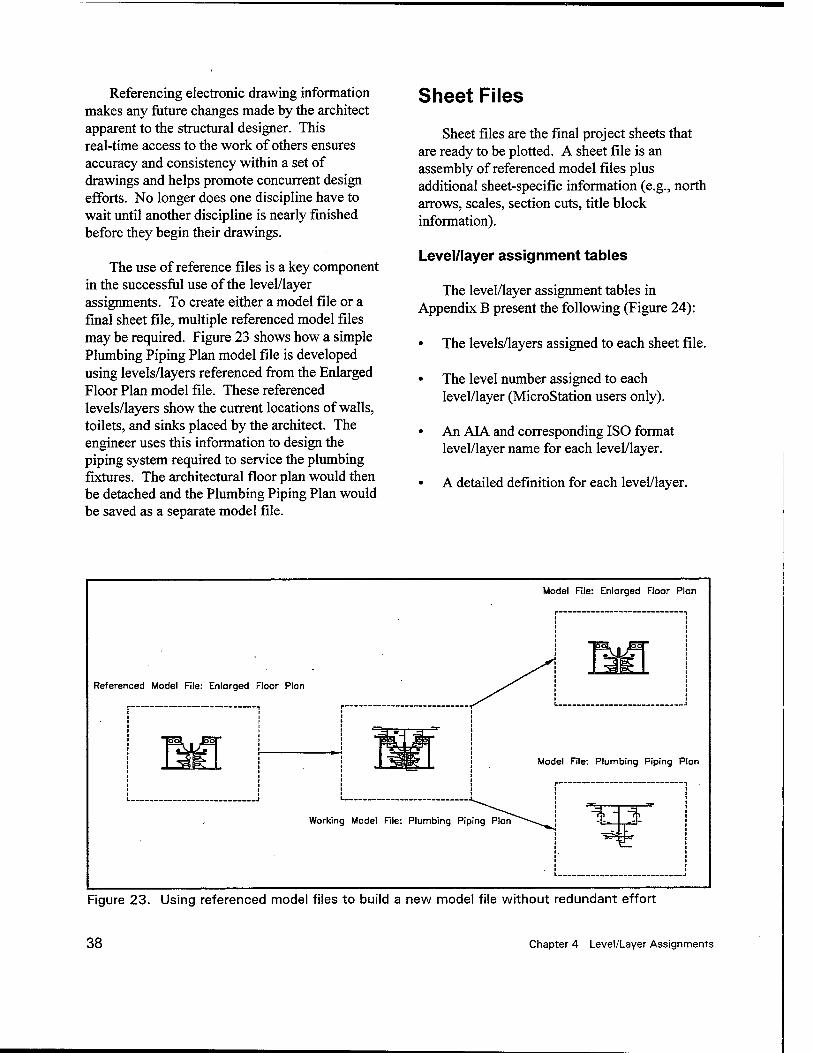
Referencing electronic drawing information makes any future changes made by the architect apparent to the structural designer. This real-time access to the work of others ensures accuracy and consistency within a set of drawings and helps promote concurrent design efforts. No longer does one discipline have to wait until another discipline is nearly finished before they begin their drawings.
The use of reference files is a key component in the successful use of the level/layer assignments. To create either a model file or a final sheet file, multiple referenced model files may be required. Figure 23 shows how a simple Plumbing Piping Plan model file is developed using levels/layers referenced from the Enlarged Floor Plan model file. These referenced levels/layers show the current locations of walls, toilets, and sinks placed by the architect. The engineer uses this information to design the piping system required to service the plumbing fixtures. The architectural floor plan would then be detached and the Plumbing Piping Plan would be saved as a separate model file.
Sheet Files
Sheet files are the final project sheets that are ready to be plotted. A sheet file is an assembly of referenced model files plus additional sheet-specific information (e.g., north arrows, scales, section cuts, title block information).
Level/layer assignment tables
The level/layer assignment tables in Appendix B present the following (Figure 24):
• The levels/layers assigned to each sheet file.
• The level number assigned to each level/layer (MicroStation users only).
• An AIA and corresponding ISO format level/layer name for each level/layer.
• A detailed definition for each level/layer.
Referenced Model File: Enlorged Floor Plon
L J
Model File: Enlarged Floor Plon
Working Model File: Plumbing Piping Plan
Figure 23. Using referenced model files to build a new model file without redundant effort
38 Chapter 4 Level/Layer Assignments
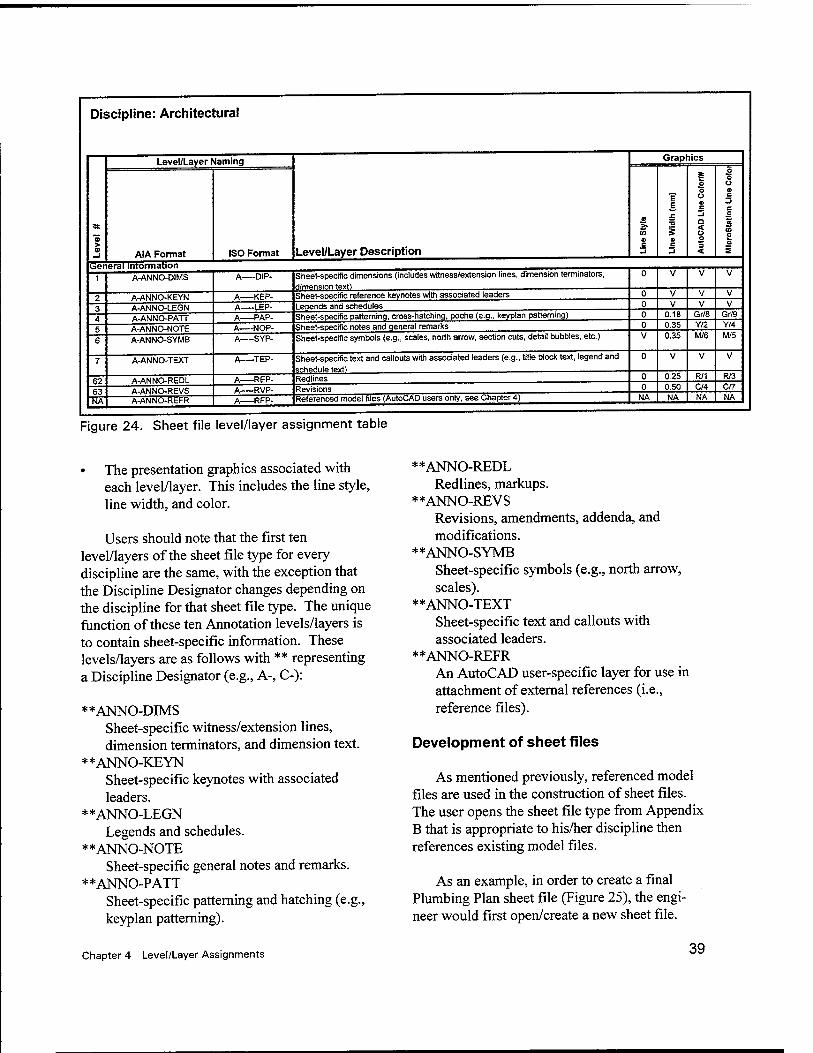
Discipline: Architectural
"5 > o
Level/Layer Naming
Level/Layer Description
Graphics
AIA Format ISO Format
a
in a c -J
? E,
s O C 3
o o Ü a> c "3 a < o o 3 <
o o u o c -1 c
£ in 0 o E
0!oi eral inrormation
1 A-ANNO-DIMS A DIP- Sheet-specific dimensions (includes witness/extension lines, dimension terminators, dimension text!
0 V V V
2 A-ANNO-KEYN A KEP- Sheet-specific reference keynotes with associated leaders 0 0
V V
V V
V V
■i 4 A-ANNO-PATT A PAP- Sheet-specific patterning, cross-hatching, poche (e.g., keyplan patterning) 0 0.18 Gr/8 Gr/9
S A-ANNO-NOTE A NOP- Sheet-specific notes and qeneral remarks 0 0.35 Y/2 Y/4
6 A-ANNO-SYMB A SYP- Sheet-specific symbols (e.g., scales, north arrow, section cuts, detail bubbles, etc.) V 0.35 M/6 M/5
7 A-ANNO-TEXT A TEP- Sheet-specific text and callouts with associated leaders (e.g., title block text, legend and schedule text)
0 V V V
R? A-ANNO-REDL A REP- Redlines 0 0.25 R/1 R/3
fi? A-ANNO-REVS A RVP- Revisions 0 0.50 C/4 C/7
NA A-ANNO-REFR A RFP- Referenced model files (AutoCAD users only, see Chapter 4) NA NA NA NA
Figure 24. Sheet file level/layer assignment table
• The presentation graphics associated with each level/layer. This includes the line style, line width, and color.
Users should note that the first ten level/layers of the sheet file type for every discipline are the same, with the exception that the Discipline Designator changes depending on the discipline for that sheet file type. The unique function of these ten Annotation levels/layers is to contain sheet-specific information. These levels/layers are as follows with ** representing a Discipline Designator (e.g., A-, C-):
**ANNO-DIMS Sheet-specific witness/extension lines, dimension terminators, and dimension text.
**ANNO-KEYN Sheet-specific keynotes with associated leaders.
**ANNO-LEGN Legends and schedules.
**ANNO-NOTE Sheet-specific general notes and remarks.
**ANNO-PATT Sheet-specific patterning and hatching (e.g., keyplan patterning).
**ANNO-REDL Redlines, markups.
**ANNO-REVS Revisions, amendments, addenda, and modifications.
**ANNO-SYMB Sheet-specific symbols (e.g., north arrow, scales).
**ANNO-TEXT Sheet-specific text and callouts with associated leaders.
**ANNO-REFR An AutoCAD user-specific layer for use in attachment of external references (i.e., reference files).
Development of sheet files
As mentioned previously, referenced model files are used in the construction of sheet files. The user opens the sheet file type from Appendix B that is appropriate to his/her discipline then references existing model files.
As an example, in order to create a final Plumbing Plan sheet file (Figure 25), the engi- neer would first open/create a new sheet file.
Chapter 4 Level/Layer Assignments 39
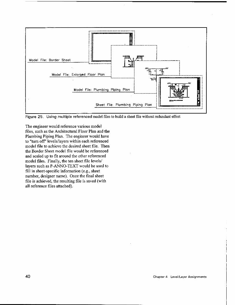
Model File: Border Sheet
Model File: Enlorged Floor Plan
Model Rle: Plumbing Piping Plan i ,
Sheet File: Plumbing Piping Plan
<\L "• [III
558——
I I
Figure 25. Using multiple referenced model files to build a sheet file without redundant effort
The engineer would reference various model files, such as the Architectural Floor Plan and the Plumbing Piping Plan. The engineer would have to "turn off" levels/layers within each referenced model file to achieve the desired sheet file. Then the Border Sheet model file would be referenced and scaled up to fit around the other referenced model files. Finally, the ten sheet file levels/ layers such as P-ANNO-TEXT would be used to fill in sheet-specific information (e.g., sheet number, designer name). Once the final sheet file is achieved, the resulting file is saved (with all reference files attached).
40 Chapter 4 Level/Layer Assignments
5 Standard Symbology
Introduction
A "cell" in MicroStation and a "block" in AutoCAD are groups of graphical elements that can be manipulated as a single entity. Examples of typical cells/blocks are windows, doors, graphic scale keys, furniture, etc. The use of such symbology enhances CADD productivity and provides an excellent opportunity for CADD standardization.
Electronic Version of the Symbology/Elements
Deliverables
Within the electronic deliverables available as part of the A/E/C CADD Standard, the following symbology is provided (Figure 26):
• MicroStation cells contained in cell libraries (.eel) and custom line styles contained in resource files (.rsc).
• AutoCAD blocks, each in an individual drawing (.dwg) file, patterns in a pattern library file (.pat), multilines in a multiline library file (.mln), and custom line styles in a line type library file (.lin).
Line styles
Line style definitions determine the particular dash-dot sequence and relative length
of dashes, blank spaces, and the characteristics of any included text or shapes. Working with line styles provides a means of distinguishing the purpose of one line from another.
AutoCAD and MicroStation both provide a set of standard line styles, as well as allowing the user to define custom line styles. In AutoCAD these custom line styles are defined in a line type library file (.lin) and a multiline library file (.mln). In MicroStation, custom line styles are contained in resource files (.rsc) (see Chapter 3 "Line Types/Styles" for more information.
Note: Custom line styles do not readily translate between systems; therefore users should anticipate that translated custom line styles may revert into their primitive graphics.
Tabulated Version of the Sym bology/Elements
Graphical presentations of the entire symbology library are shown in Appendix D "A/E/C CADD Symbology."
The symbology library contains four types of elements: Lines, Patterns, Symbols, and Objects. Lines are defined as a graphical representation of linear drawing features (e.g., utility lines, fence lines, contours). Patterns are defined as repeated drawing elements (e.g., lines, dots, circles) within a defined area. Symbols are defined as MicroStation cells or AutoCAD blocks that are
Chapter 5 Standard Symbology 41
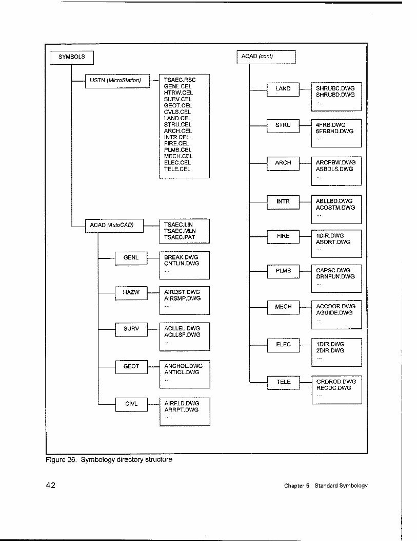
SYMBOLS
USTN (MicroStation)
ACAD (AutoCAD)
GENL
HAZW
SURV
GEOT
CIVL
TSAEC.RSC GENLCEL HTRW.CEL SURV.CEL GEOT.CEL CVLS.CEL LAND.CEL STRU.CEL ARCH.CEL INTR.CEL FIRE.CEL PLMB.CEL MECH.CEL ELEC.CEL TELE.CEL
TSAEC.LIN TSAEC.MLN TSAEC.PAT
BREAK.DWG CNTLIN.DWG
AIRQST.DWG AIRSMP.DWG
ACLLEL.DWG ACLLSF.DWG
ANCHOL.DWG ANTICLDWG
AIRFLD.DWG ARRPT.DWG
ACAD (cont)
LAND SHRUBC.DWG SHRUBD.DWG
STRU 4FRB.DWG 6FRBHD.DWG
ARCH ARCPBW.DWG ASBDLS.DWG
INTR ABLLBD.DWG ACOSTM.DWG
FIRE 1DIR.DWG ABORT. DWG
PLMB CAPSC.DWG DRNFUN.DWG
MECH ACCDOR.DWG AGUIDE.DWG
ELEC 1DIR.DWG 2DIR.DWG
TELE GRDROD.DWG RECDC.DWG
Figure 26. Symbology directory structure
42 Chapter 5 Standard Symbology
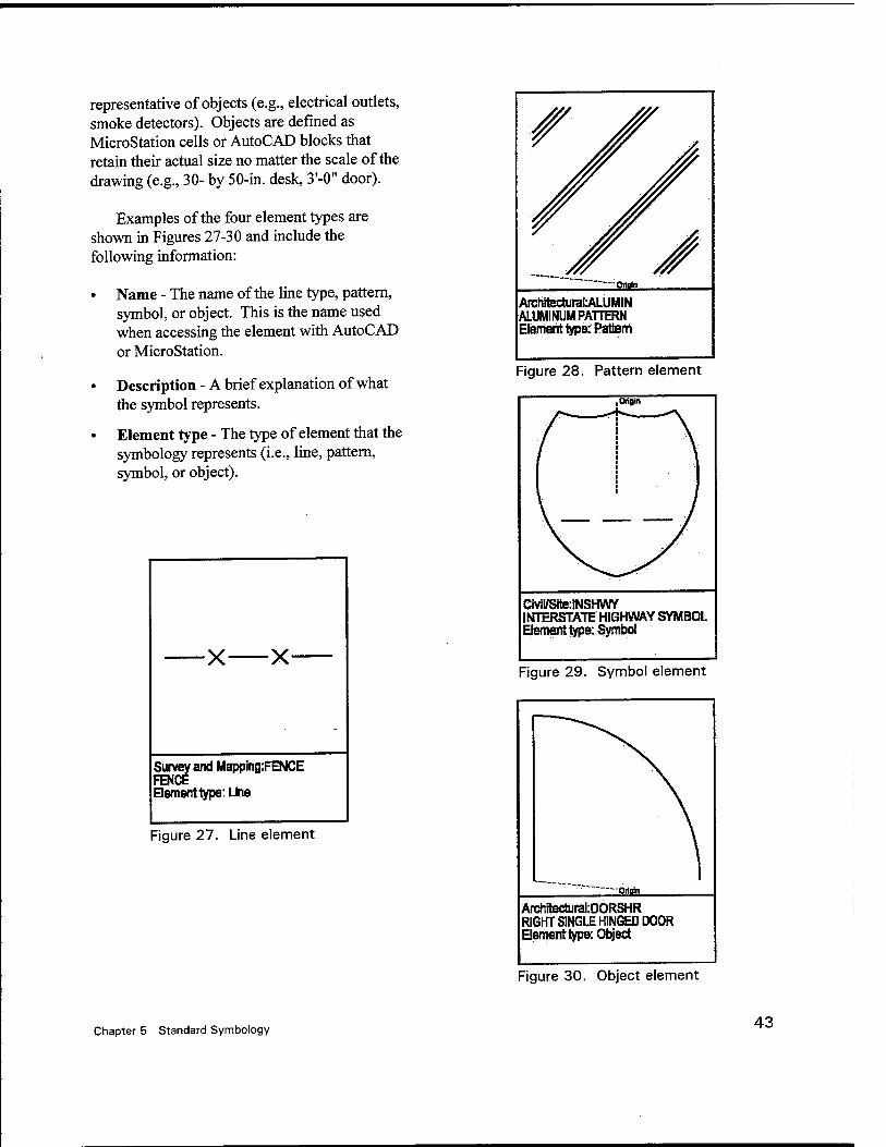
representative of objects (e.g., electrical outlets, smoke detectors). Objects are defined as MicroStation cells or AutoCAD blocks that retain their actual size no matter the scale of the drawing (e.g., 30- by 50-in. desk, 3'-0" door).
Examples of the four element types are shown in Figures 27-30 and include the following information:
• Name - The name of the line type, pattern, symbol, or object. This is the name used when accessing the element with AutoCAD or MicroStation.
• Description - A brief explanation of what the symbol represents.
• Element type - The type of element that the symbology represents (i.e., line, pattern, symbol, or object).
X- X
Suvey and Mapping:FENCE FENCE Hementtype: Line
Figure 27. Line element
• Origin
ArchfecturaLALUMIN ALUMINUM PATTERN Element type: Pattern
Figure 28. Pattern element
.Origin
Civil/Site:!NSHVW INTERSTATE HIGHWAYSYMBOL Element type: Symbol
Figure 29. Symbol element
"Origin
ArchftechjraliDORSHR RIGHT SINGLE HINGED DOOR Element type: Object
Figure 30. Object element
Chapter 5 Standard Symbology 43
6 A/E/C CADD Standard Implementation Tools
CADD users throughout the DoD have indicated a need for customized shortcuts or utilities to facilitate efficient production of architectural and engineering CADD docu- ments. Since the distribution of Release 1.4 of the A/E/C CADD Standard, users have been requesting tools to implement this detailed standard.
To meet this demand, the CADD/GIS Technology Center has developed applications for both AutoCAD and MicroStation that help in implementing the CADD Standard (i.e., the user will rarely have to refer to the standard document when developing CADD files).
The MicroStation-based tool (called Workspace) is distributed in three components: the Workspace generator, the Workspace itself, and a standard compliance checker. The generator creates the workspace tools (palettes, icons, etc.) using a Microsoft Access database that contains all the information within the model file tables in the CADD Standard. Using a "generator" gives system administrators the ability to edit the Access database and rerun the generator to create a Workspace that meets site- specific needs. The Workspace (Figure 31) allows the user to select the type of model or sheet file he/she wants to create (e.g., Architectural Floor Plan), and a palette of the various items that can be placed in that type of file is generated (e.g., doors, windows). The user then selects the specific type of item required (e.g., full height doors, partial height
doors, door symbols) and the workspace sets the proper level settings (e.g., level number, color, line weight, line style).
The final part of the workspace is the checker (Figure 32). The checker can evaluate individual model files to determine if they are in compliance with the A/E/C CADD Standard. The checker records which elements are not in compliance and can locate those elements for the user within the file.
The AutoCAD counterpart to the MicroStation A/E/C Workspace is also available. Using the same Access database as the MicroStation version, the AutoCAD A/E/C Workspace also assists the user in setting the correct drawing layer properties (Figure 33). The symbology in the A/E/C CADD Standard is also available for placement.
The Coast Guard is also adapting their CE-CADD software, which runs in AutoCAD, to follow the A/E/C CADD Standard. This product will be completed in the latter half of FY2001.
Further information on these implementa- tion tools can be obtained from the CADD/GIS Technology Center web site at http://tsc. wes. army. mil.
44 Chapter 6 A/E/C CADD Standard Implementation Tools
Edä Element Settings Tools Uhtrfes Workspace Window
A^DBH^BBcB 'irsdo«1 ■'Too View
ItiWl^Wxl
Ü! Full height {to ceiling) door swing and leaf Door rw^ber and syrrfjbl, hardware group.
Help
Architectural Telecommunications:
Ova Electrical Fire Protection. •
Cieneral
Geotechnical Hazardous Materials Interiors:- ; .-•... Landscape -....-: Mechanical •■ 'Plombihg Suudtura1
Survey/Mapping'.' yj
Details. ■ ■ ■ Elevations (Exterior and Interior). Eqiipment Plan
Floor Plan Aiea.Calculations/Occupancy Plan;' .Reflect^ Qeing Plan; '■■; V,..;d
Poof Plan. '";':'" '''i'r'y '':^::^\
SheeiFi^ ::■■/_}';■■ C :^{:\) Building Sections £'~ ' ■■% ;i
Figure 31. MicroStation workspace
Chapter 6 A/E/C CADD Standard Implementation Tools 45
Non-compliant element
I ^
gA/E/C Standaids Checket M
ft ~Elenfetf EuorTjipe S 4Uribute i
k iLine Strinq Linear Syrnootogy NO View:; .1 |
f
P. I-
Line Siring Linear Symböiogy NO Line Slr'mg Linear S^bology NO
Test TeriSymbology YES Terf TextSymbology YES
Locates Non-compliant Elements in Drawing
Ucde'eSird--]
Update^'|
1 Sr -flS^S^: Res<m>p'e
\ \ \ v_ Initiates Checker
Display List of Non-compliant Elements within Drawing
Fig ure 32. Workspace checker
T|TSWS
Layer
Disciplines Drawing Types:
3Ü Pattern If Symbol/Object j M bceiläreöüg
es&p
I Architectural
Description:
illFloor-Rlan -I Walls
Lay er Names:
^|A^WA^fDEN H| wall identification«upe text or tags
Line Weight: jggLine Coforjqyan Line Typejg"
Status OverRide: f" ; TEXT SEND- EST
Figure 33. AutoCAD workspace
46 Chapter 6 A/E/C CADD Standard Implementation Tools
References
American Institute of Architects. (1988). Architectural graphic standards. 8* ed., John Wiley and Sons, New York.
American Institute of Architects. (2001). AM CAD layer guidelines: U.S. national CAD standard version 2. American Institute of Architects Press, Washington, DC.
American National Standard Institute. (1972). "Graphic symbols for electrical wiring and layout diagrams used in architect and building construction," ANSI Y32.9-1972, Institute of Electrical and Electronics Engineers, New York.
American Society of Heating, Refrigerating and Air-Conditioning Engineers, Inc. (1997). "1997 ASHRAE fundamentals handbook," Atlanta, GA.
American Society of Mechanical Engineers. (1995). "Decimal inch drawing sheet size and format," ASME Y14.1-1995, New York.
. (1995). "Metric drawing sheet size and format," ASME Y14.1M-1995, New York.
American Society of Plumbing Engineers. (1998). "Data book Volume 1: Fundamentals of plumbing engineering," Chicago, IL.
American Society for Testing and Materials. (1999). "Standard practice for the use of metric (SI) units in building design and construction (Committee E-6 Supplement to E380)," ASTM E621-94, Philadelphia, PA.
Construction Metrication Council. (1998). Construction metrication. Vol 7, Issue 1, National Institute of Building Sciences, Washington, DC.
Construction Specifications Institute. (2001). Uniform drawing system. Alexandria, VA.
Department of Commerce/Department of Defense. (1997). United States of America nautical chart symbols, abbreviations, and terms. 10th ed., Department of Commerce, Washington, DC.
Headquarters, U. S. Army Corps of Engineers. (1990). "Standards manual for U. S. Army Corps of Engineers Computer-Aided Design and Drafting (CADD) systems," Engineer Manual 1110-1-1807, Washington, DC.
References 47
International Organization for Standardization. (1982). "Technical drawings - General principles of presentation," ISO 128, Switzerland.
. (1998). "Technical product documentation - Organization and naming of layers for CAD - Part 2: Concepts, format and codes used in construction documentation," ISO 13567-2, Switzerland.
National Fire Protection Association. (1999). "Standard for fire safety symbols," NFPA 170, Quincy, MA.
Sheet Metal and Air Conditioning Contractors' National Association. (1995). HVAC duct construction standards-metal and flexible. 2nd ed., Chantilly, VA.
The CADD/GIS Technology Center. (1999). "A/E/C CADD standard: Main text and appendices A-E," U.S. Army Engineer Research and Development Center, Vicksburg, MS.
. (2001). "Spatial data standards/facility management standards," Release 2.0, U.S. Army Engineer Research and Development Center, Vicksburg, MS.
48 References
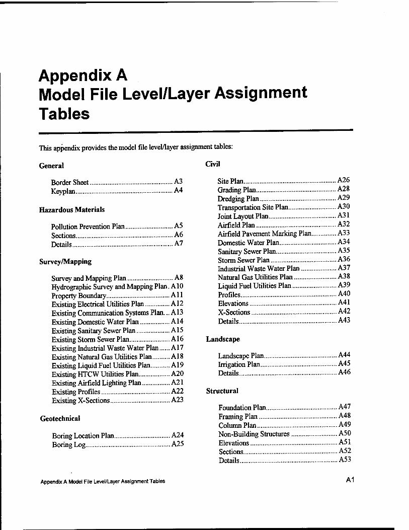
Appendix A Model File Level/Layer Assignment Tables
This appendix provides the model file level/layer assignment tables:
General
Border Sheet A3 Keyplan A4
Hazardous Materials
Pollution Prevention Plan A5 Sections A6 Details A7
Survey/Mapping
Survey and Mapping Plan A8 Hydrographie Survey and Mapping Plan. A10 Property Boundary All Existing Electrical Utilities Plan A12 Existing Communication Systems Plan... A13 Existing Domestic Water Plan A14 Existing Sanitary Sewer Plan A15 Existing Storm Sewer Plan A16 Existing Industrial Waste Water Plan A17 Existing Natural Gas Utilities Plan A18 Existing Liquid Fuel Utilities Plan A19 Existing HTCW Utilities Plan A20 Existing Airfield Lighting Plan A21 Existing Profiles A22 Existing X-Sections A23
Geotechnical
Boring Location Plan A24 Boring Log A25
Civil
Site Plan A26 Grading Plan A28 Dredging Plan A29 Transportation Site Plan A30 Joint Layout Plan A31 Airfield Plan A32 Airfield Pavement Marking Plan A33 Domestic Water Plan A34 Sanitary Sewer Plan A35 Storm Sewer Plan A36 Industrial Waste Water Plan A37 Natural Gas Utilities Plan A38 Liquid Fuel Utilities Plan A39 Profiles A40 Elevations..... A41 X-Sections A42 Details A43
Landscape
Landscape Plan A44 Irrigation Plan A45 Details A46
Structural
Foundation Plan A47 Framing Plan A48 Column Plan A49 Non-Building Structures A50 Elevations A51 Sections A52 Details A53
Appendix A Model File Level/Layer Assignment Tables A1
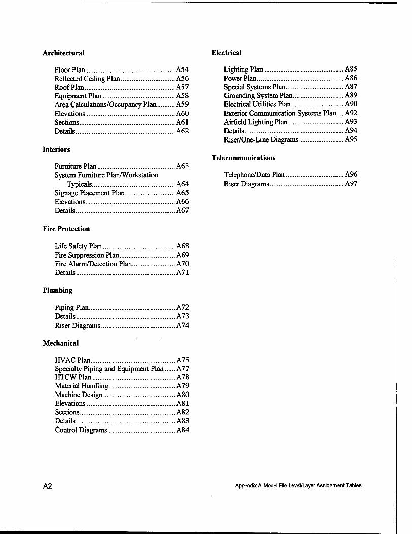
Architectural Electrical
Floor Plan A54 Reflected Ceiling Plan A56 Roof Plan A57 Equipment Plan A58 Area Calculations/Occupancy Plan A59 Elevations A60 Sections A61 Details A62
Interiors
Furniture Plan A63 System Furniture Plan/Workstation
Typicals A64 Signage Placement Plan A65 Elevations A66 Details A67
Fire Protection
Life Safety Plan A68 Fire Suppression Plan A69 Fire Alarm/Detection Plan A70 Details A71
Plumbing
Piping Plan A72 Details A73 Riser Diagrams A74
Mechanical
HVAC Plan A75 Specialty Piping and Equipment Plan A77 HTCWPlan A78 Material Handling A79 Machine Design A80 Elevations A81 Sections A82 Details A83 Control Diagrams A84
Lighting Plan A85 Power Plan A86 Special Systems Plan A87 Grounding System Plan A89 Electrical Utilities Plan A90 Exterior Communication Systems Plan... A92 Airfield Lighting Plan A93 Details A94 Riser/One-Line Diagrams A95
Telecommunications
Telephone/Data Plan A96 Riser Diagrams A97
A2 Appendix A Model File Level/Layer Assignment Tables
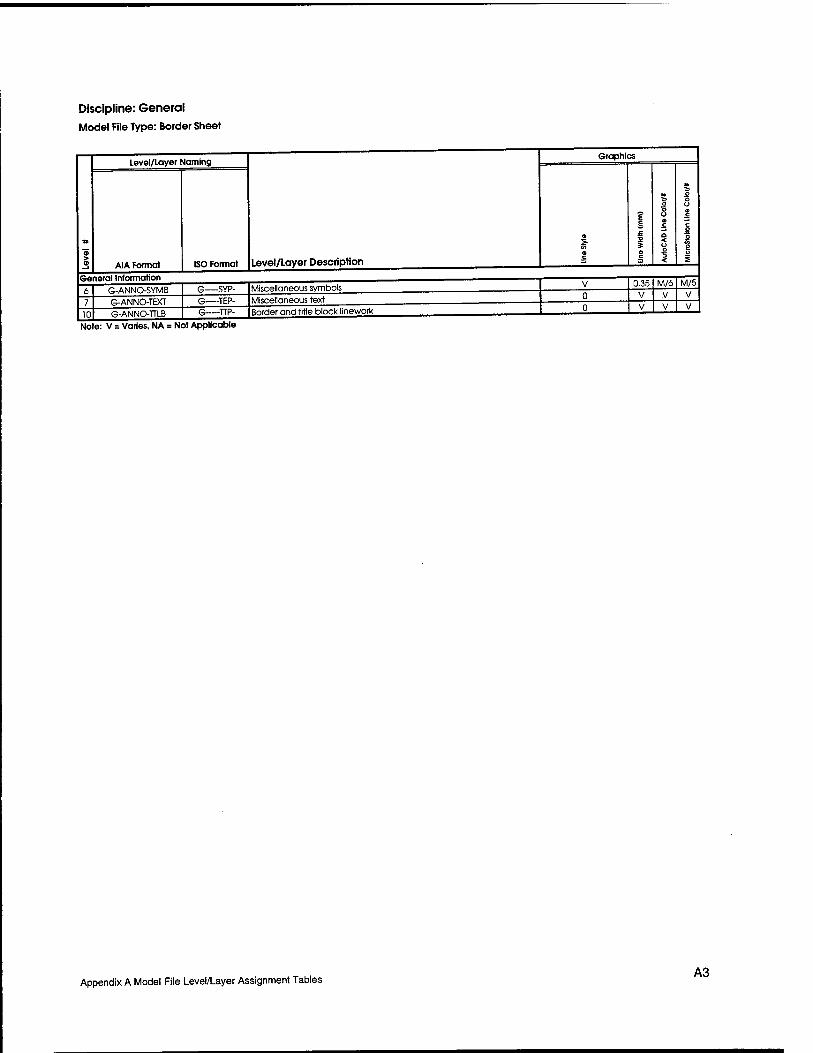
Discipline: General Model File Type: Border Sheet
Level/layer Naming
A1A Format ISO Format
Graphics
Level/Layer Description General Information
10
G-ANNO-SYMB G-ANNO-TEXT G-ANNO-TTLB
G SYP- -TEP- -TTP-
Miscellaneous symbols 0.35 M/6 M/5
Miscellaneous text Border and title block linework
Note: V = Varies, NA = Not Applicable
Appendix A Model File Level/Layer Assignment Tables A3
Discipline: General
Model File Type: Key Plan
*
Level/Layer Naming
Level/Layer Description
Graphics
AIA Format ISO Format
CO o c
E E, £
o c
O o Ü a c a 5 o <
o o u a c c o o 2 o £
3 G-ANNO-NPLT G NPP- Non-plotting qraphlc information V 0.18 B/b B/l
4 G-ANNO-PATT G PAP- Miscellaneous patterning and hatching 0 0.18 Gr/8 Gr/9
6 G-ANNO-SYMB G SYP- Miscellaneous symbols V 0.35 M/6 M/5
7 G-ANNO-TEXT G TEP- Miscellaneous text and callouts with associated leaders 0 V V V
NA G-ANNO-REFR G RFP- Reference files (AutoCAD users only, see Chapter 4) NA NA NA NA
Grid Unes
11 G-GRID-EXTR G-GRIDEXM- Column grid outside building 7 0.18 B/S B/l
12 G-GRID-1DEN G-GRIDIDM- Column arid tags 0 0.25 R/l R/3
15| G-PLAN-OTLN | G-PLANOTM- |Floor outline/perimeter/building footprint I 0 I 0.351 M/61M/5
201 G-SITE-OTLN | G-SITEOTM- |Site plan - key map 1 0 I 0.351M/61 M/5
Note: V = Varies, NA = Not Applicable
A4 Appendix A Model File Level/Layer Assignment Tables
Discipline: Hazardous Materials Model File Type: Pollution Prevention Plan
Level/Layer Naming
AIA Format
General Information
NA H-ANNO-REFR
Buildings
Storage Facilities
H-ANNO-DIMS H-ANNO-KEYN H-ANNO-NPLT
H-ANNO-PATT
H-ANNO-NOTE H-ANNO-SYMB
H-ANNO-TEXT
12
H-BLDG-IDEN
H-BLDG-OTLN
13 14
15
H-STOR-HAZM
H-STOR-HA2W H-STOR-IDEN
Monitoring Stations
17
19
20
21 22
H-MNST-GWTR H-MNST-SWTR
H-MNST-AIRQ
H-MNST-SOIL H-MNST-LAND H-MNST-IDEN
Pollution Areas
Decontamination
Emergency Fixtures
23 24
25 26
H-POLL-ORIG H-POLL-CONC H-POLL-POTN
H-POLL-IDEN
29 30
H-DECN-EQPM H-DECN-IDEN
31 32
H-FIXT-EYEW H-FIXr-SHOW
Disposal Areas
34
35
36 37
H-DISP-HAZW H-D1SP-MUNT
H-DISP-TANK H-DISP-IDEN
Sample Points
39
40
42
43 44
45
46
47
48
H-SAMP-AIRS H-SAMP-BIOL
H-SAMP-GWTR
H-SAMP-SEDI
H-SAMP-SOIL
H-SAMP-SOU H-SAMP-SWTR
H-SAMP-WAST
ISO Format level/Layer Description
H DIP
H KEP- Reference keynotes with associated leaders
H—NPP- Non-plorting graphic information
H—PAP-
H—NOP- H—SYP-
H TEP-
H RFP-
Witness/extension lines, dimension terminators, dimension text
Miscellaneous patterning and hatching
General notes and general remarks
Miscellaneous symbols Miscellaneous text and callouts with associated leaders Reference files (AutoCAD users only, see Chapter 4)
H-BLDGIDM- Annotation
H-BIDGOTM- Command posts, information centers
H-STORHMM- Hazardous materials
H-STORHWM-
H-STORIDM-
Hazardous waste Annotation
H-MNSTGWM- Ground water
H-MNSTSWM- Surface water
H-MNSTAIM- Air quality
H-MNSTSOM- H-MNSTLAM-
H-MNSTIDM-
Soil gas Landfill gas Annotation
H-POLLORM-
H-POLLCOM-
Point of pollution origin
H-POLLPOM-
H-POLUDM-
Polluted area of concern Potential spill, emission, or release source
Annotation
H-DECNEQM-
H-DECNIDM-
Decontamination equipment
Annotation
H-FIXTEYM-
H-FIXTSHM-
Emergencv eyewashes Emergency showers
H-DISPHWM- Hazardous waste
H-DISPMUM- Munitions
H-DISPTAM-
H-DISPIDM-
Spill containment tanks
Annotation
H-SAMP-MAGN
H-SAMP-IDEN
H-SAMPAIM- Air samples
H-SAMPBIM- Biological samples
H-SAMPGWM- Ground water samples
H-SAMPSEM- Sediment samples
H-SAMPSOM-
H-SAMPSLM-
H-SAMPSWM-
H-SAMPWAM-
H-SAMPMAM-
H-SAMP1DM-
Soil samples Solid material samples
Surface water samples
Waste samples Magnetometer location points
Annotation
Demolition (used only in creating Existing/Demolition model files)
56 57 58
H-STAT-DEMO-PHS1
H-STAT-DEMO-PHS2 H-STAT-DEMO-PHS3
-M-D—1
H M-D—2
H- -M-D—-3
Demolition - phase 1 Demolition - phase 2 Demolition - phase 3
Note: V = Varies, NA = Not Applicable
Graphics
NA
0.18 0.18
0.35
0.35
B/5 Gr/8
Y/2 M/6
NA NA
0.35
0.35
0.35 0.35 0.35
0.25
Y/2
Y/2
M/6 M/6
M/6
G/3
0.25 0.25
0.25
0.25
0.25
G/3
G/3
G/3 G/3
G/3
B/l Gr/9
Y/4 M/5
NA
Y/4
Y/4
M/5 M/5
M/5
G/2 G/2
G/2 G/2
G/2
G/2
0,35 0.35
0.35
0.35
0.25
Y/2 Y/2 Y/2
Y/2
0.35 R/l M/6
0.25
0.25
0.18
0.18
G/3
G/3
B/5
0.35 0.35
B/5
M/6
M/6
Y/4 Y/4 Y/4
Y/4
R/3
M/5
G/2
G/2
"B7T B/l M/5
M/5
0.25 R/l 0.25 0.25 0.25 0.25 0.25 0.25 0.25 0.25 0.25
0.50
R/l R/l R/l
R/1
R/l R/l R/l
R/l
R/l
203
R/3 R/3 R/3 R/3 R/3 R/3 R/3 R/3 R/3 R/3
45 0,50 0.50
83 163
Appendix A Model File Level/Layer Assignment Tables A5

Discipline: Hazardous Materials
Model File Type: Sections
« >
Level/Layer Naming
Level/Layer Description
Graphics
AIA Format ISO Format a c
I £ * 5 a c
o o o a c a < o o 1
O O Ü o C
C O o 2 I
1 H-ANNO-DIMS H DIP- Witness/extension lines, dimension terminators, dimension text 0 V V V
2 H-ANNO-KEYN H—KEP- Reference keynotes with associated leaders 0 V V V
3 H-ANNO-NPLT H—NPP- Non-plottinq graphic information V a IB ti/b B/l
4 H-ANNO-PATT H PAP- Miscellaneous patterning and hatching 0 U.I8 yr/B Gr/V
5 H-ANNO-NOTE H—NOP- General notes and qeneral remarks 0 0.35 Y/2 Y/4
6 H-ANNO-SYMB H—SYP- Miscellaneous symbols V 0.35 M/6 M/5
7 H-ANNO-TEXT H—TEP- Miscellaneous text and callouts with associated leaders 0 V V V
NA H-ANNO-REFR H—RFP- Reference files (AutoCAD users only, see Chapter 4) NA NA NA NA
45 H-SECT-1DEN H-SECTIDM- Component identification numbers 0 0.35 Y/2 Y/4
46 H-SECT-MBND H-SECTMBM- Material beyond section cut 0 U. 18 ti/b B/l
47 H-SECT-MCUT H-SECTMCM- Material cut by section 0 0.50 C/4 C//
48 H-SECT-PATT H-SECTPAM- Textures and hatch patterns 0 0.18 Gr/8 Gr/9
56 H-STAT-DEMO-PHS1 H M-D—1 Demolition - phase 1 0 0.50 203 45
57 H-STAT-DEMO-PHS2 H M-D—2 Demolition - phase 2 0 U.50 03 42
58 H-STAT-DEMO-PHS3 H M-D—3 Demolition - phase 3 0 Ü.50 163 41
Note: V = Varies, NA = Not Applicable
A6 Appendix A Model File Level/Layer Assignment Tables

Discipline: Hazardous Materials
Model File Type: Details
level/Layer Naming
AIA Format
General Information
ISO Format
Graphics
level/Layer Description
H-ANNO-DIMS H-ANNO-KEYN
H-ANNO-NPLT H-ANNO-PATT
H-ANNO-SYMB
H-ANNO-TEXT Detail Information
H DIP-
H KEP- H NPP-
-PAP-
H SYP-
H TEP-
Witness/extension lines, dimension terminators, dimension text
Reference keynotes with associated leaders
Non-plotting graphic information
Miscellaneous patterning Reference bubbles, matchlines and breaklines
0.18
0.18
0.35
Detail title text, text and associated leaders, notes
11 12
Demolition (used only in creating Existing/Demolition model files) 13
H-DETL-GRPH
H-DETL-METR
H-DETl-INPD
H-DETLGRM- Graphics, gridlines, non-text items
H-DETLMEM-
H-DETUNM-
Metric-specific dimensions and notes Inch-pound-specific dimensions and notes
56 57 58
H-STAT-DEMO-PHS1 H-STAT-DEMO-PHS2
H-S1AT-DEMO-PHS3
H-- -M-D—1 H M-D—2
H- -M-D—-3
Note: V = Varies, NA = Not Applicable
Demolition - phase 1
Demolition - phase 2
B/5
Gr/8
M/6
0.25 G/3 0.25
0.50
R/l
V
V
B/1 Gr/9
M/5
G/2
R/3
203
Demolition - phase 3
0.50
0.50
83
163
45 42
41
Appendix A Model File Level/Layer Assignment Tables A7
Discipline: Survey/Mapping Model File Type: Survey and Mapping Plan
* >
Level/Layer Naming
Level/Layer Description
Graphics
AIA Format ISO Format
in a c
E E £
f c
o o o o c a < o o <
o o o « c o
o 3» o o s
General Information
1 V-ANNO-DIMS V—DIP- Witness/extension lines, dimension terminators, dimension text 0 V V V
2 V-ANNO-KEYN V—KEP- Reference keynotes with associated leaders 0 V V V
3 V-ANNO-NPLT V—NPP- Non-plotting graphic information V 0.18 B/5 B/l
4 V-ANNO-PATT V PAP- Miscellaneous patterning and hatching 0 0.18 Gr/8 Gr/9
5 V-ANNO-NOTE V NOP- General notes and general remarks 0 0.35 Y/2 Y/4
6 V-ANNO-SYMB V SYP- Miscellaneous symbols V 0.35 M/6 M/5
7 V-ANNO-TEXT V TEP- Miscellaneous text and callouts with associated leaders 0 V V V
NA V-ANNO-REFR V RFP- Reference files (AutoCAD users only, see Chapter 4) NA NA NA NA
Survey Lines
8 V-SURV-DATA V-SURVDAM- Survey data (benchmarks and horizontal control points or monuments) 0 0.35 M/6 M/5
9 V-SURV-UNE V-SURVLIM- Survey, baseline, and control line 2 0.50 C/4 C/7
10 V-SURV-IDEN V-SURVIDM- Survey, baseline, and control line annotation 0 0.35 M/6 M/5
Buildings and Structures
11 V-8LDG-OTLN V-BLDGOTM- Buildings and other structures 0 0.70 W/7 W/0
12 V-BLDG-IDEN V-BLDGIDM- Building and other stucture annotation 0 0.35 Y/2 Y/4
Site
13 V-SITE-FENC V-SITEFEM- Fences and handrails 0, FENCE 0.35 M/6 M/5
14 V-SITE-FENC-IDEN V-STTERM- Fence, handrail, ramp, and trail annotation 0 0.35 M/6 M/5
15 V-STTE-STRC V-S1TESRM- Structures (bridges, sheds, foundation pads, footings, etc.) 0 0.35 22 22
16 V-SITE-IDEN V-SITEIDM- Existing site feature/structure annotation 0 0.35 M/6 M/5
17 V-SITE-OTLN V-SITEOTM- Existing site features (play structures, bike racks, benches, recreational equipment)
0 0.50 C/4 C/7
18 V-SITE-EROS V-STTEERM- Riprap, revetments/stone protection, breakwaters, dikes, jetties, and
drains
0 0.25 R/l R/3
19 V-SITE-EWAT V-SITEEWM- Water features 0 0.35 162 33
20 V-SITE-STRS V-SITESTM- Stairs and ramps 0 0.35 M/6 M/5
21 V-SITE-WALK V-SITEWAM- Walks, trails, and bicycle paths 0 0.35 Y/2 Y/4
22 V-SITE-VEGE V-SITEVEM- Existing treelines and vegetation 0, TREEl 0.35 82 18
Utilities (for more detailed surveys, use Survey and Mapping Utility model files)
23 V-UTIL-SSWR V-UTILSSM- Sanitary lines and manholes 0. SSWAFX 0.50 C/4 C/7
24 V-UTIL-SSWR-IDEN V-UTILSDM- Sanitary annotation 0 0.35 Y/2 Y/4
25 V-UTIL-WATR V-UTILWAM- Water lines, hydrants, tanks 0, WATRX 0.50 C/4 C/7
26 V-UTIL-WATR-IDEN V-UTILWIM- Water annotation 0 0.35 Y/2 Y/4
27 V-UTIL-NGAS V-UTILNGM- Gas lines, features, and valves 0, NTGASX 0.50 C/4 C/7
28 V-UTIL-NGAS-1DEN V-UTILNIM- Gas annotation 0 0.35 Y/2 Y/4
29 V-UT1L-STEM V-UTILSEM- Steam lines and annotation 0 0.35 Y/2 Y/4
30 V-UTIL-STRM V-UTILSTM- Storm sewer lines, culverts, manholes, and headwalls 0, STRAFX CULVRT 0.50 C/4 C/7
31 V-UTIL-STRM-IDEN V-UTILSIM- Storm sewer annotation 0 0.35 Y/2 Y/4
32 V-UTIL-ELEC V-UTILELM- Power lines, lights, telephone poles, communication lines 0. COMARX
COMUGX EPARX EPUGX ESARX
ESUGX
0.50 C/4 C/7
33 V-UTIL-ELEC-IDEN V-UTILEIM- Power/communication annotation 0 0.35 Y/2 Y/4
Pavements/Transportation
34 V-PVMT-ROAD V-PVMTROM- Roads, parking lots, railroads, airfield pavements 0, RAILS 0.35 Y/2 Y/4
35 V-PVMT-IDEN V-PVMTIDM- Road, parking lot, railroad, airfield pavement annotation 0 0.35 Y/2 Y/4
36 V-PVMT-PATT V-PVMTPAM- Joint patterns, text and dimensions 0 0.35 Y/2 Y/4
37 V-PVMT-MRKG V-PVMTMRM- Pavement markings and signs 0 0.35 Y/2 Y/4
A8 Appendix A Model File Level/Layer Assignment Tables
Discipline: Survey/Mapping Model Rio Type: Survey and Mapping Plan
Topography 38 39 40 41 42 43 44 48 49 50 51 52
V-TOPO-DTCH V-TOPO-BORE V-TOPO-COOR
V-TOPO-MAJR-IDEN V-TOPO-MAJR
V-TOPO-MINR-IDEN V-TOPO-M1NR V-TOPO-SPOT
V-TOPO-SLOP-TOPT V-TOPO-BKLN V-TOPO-DTMT V-TOPO-DTMP
V-TOPODTM- V-TOPOBOM- V-TOPOCOM- V-TOPOMAM- V-TOPOMJM- V-TOPOMIM- V-TOPOMNM- V-TOPOSPM- V-TOPOSTM- V-TOPOBKM- V-TOPODTM- V-TOPODPM-
Ditches ond swales Boring locations
0, DITCH 0
Coordinate grid ticks and text Major contours - annotation Major contours Minor contours - annotation Minor contours Spot elevations Top/toe slopes Breaklines DTM triangles DTM points
Aerial Survey
0.25 0,35 0,35 0.35 0.35 0.25 0.25 0.35 0.35 0.70 0.35 0.35
G/3 M/6 122 Y/2 Y/2 G/3 G/3 Y/2 M/6 W/7 22
M/6
53 54 55
V-AERI-PATH V-AERI-BNDY V-AERI-INDX
V-AERIPAM- V-AERIBNM- V-AERIINM-
No»e: V = Varies. NA = Not Applicable
Aerial flight lines/paths
G/2 M/5 23 Y/4 Y/4 G/2 G/2 Y/4 M/5 W/0 22
M/5
Aerial photography boundaries Aerial photo index
0.35 0.35 0.70
22 M/6 W/7
22 M/5 W/0
Appendix A Model File Level/Layer Assignment Tables A9
Discipline: Survey/Mapping
Model File Type: Hydrographie Survey and Mapping Plan
> —1
Level/Layer Naming
Level/Layer Description
Graphics
AIA Format ISO Format
w c
6
£ •a % o c
O o o a
a < o o B <
« 5 o o 9 C
C O
2 o 5
General Information
1 V-ANNO-DIMS V-—DIP- Witness/extension lines, dimension terminators, dimension text 0 V V V
2 V-ANNO-KEYN V KEP- Reference keynotes with associated leaders 0 V V V
3 V-ANNO-NPLT V NPP- Non-plotting graphic information V 0.18 B/5 B/T
4 V-ANNO-PATT V PAP- Miscellaneous patterning and hatching 0 0.18 Gr/8 Gr/9
5 V-ANNO-NOTE V—NOP- General notes and general remarks 0 0.35 Y/2 Y/4
6 V-ANNO-SYMB V SYP- Miscellaneous symbols V 0.35 M/6 M/5
7 V-ANNO-TEXT V—TEP- Miscellaneous text and callouts with associated leaders 0 V V V
NA V-ANNO-REFR V—RFP- Reference files (AutoCAD users only, see Chapter 4) NA NA NA NA
Survey lines
8 V-SURV-DATA V-SURVDAM- Survey data (benchmarks and horizontal control points or monuments) 0 0.35 M/6 M/5
9 V-SURV-UNE V-SURVLIM- Survey, baseline, and control lines 2 0.50 C/4 C/7 10 V-SURV-IDEN V-SURVIDM- Survey, baseline, and control line annotation 0 0.35 M/6 M/5
Structures
11 V-STRC-OTLN V-STRCOTM- Bridges, piers, breakwaters, docks, floats, etc. - outlines 0 0.50 C/4 C/7 12 V-STRC-IDEN V-STRCIDM- Bridges, piers, breakwaters, docks, floats, etc. - annotation 0 0.35 Y/2 Y/4
Channels
14 V-CHAN-UMT V-CHANUM- Channel limits, anchorages, turning basins, disposal areas, etc. 0 0.35 M/6 M/5
15 V-CHAN-IDEN V-CHANIDM- Channel limits, anchorages, turning basins, disposal areas, etc. - annotation
0 0.35 M/6 M/5
16 ■ V-CHAN-DACL V-CHANDAM- De-authorized channel limits, anchorages, etc. 0 0.25 G/3 G/2
17 V-CHAN-DACL-IDEN V-CHANDIM- De-authorized channel limits, anchorages, etc. - annotation 0 0.25 G/3 G/2
18 V-CHAN-CNTR V-CHANCNM- Channel centerline and survey report lines 4 0.18 B/5 B/l
19 V-CHAN-CNTR-IDEN V-CHANCIM- Channel centerline and survey report lines - annotation 0 0.18 B/5 B/l 20 V-C HAN-AIDS V-CHANAIM- Navigation aids and text 0 0.35 Y/2 Y/4
Topography
39 V-TOPO-BORE V-TOPOBOM- Boring locations 0 0.35 M/6 M/5
40 V-TOPO-COOR V-TOPOCOM- Coordinate grid ticks and text 0 0.35 122 23
41 V-TOPO-MAJR-1DEN V-TOPOMAM- Major contours - annotation 0 0.35 Y/2 Y/4
42 V-TOPO-MAJR V-TOPOMJM- Major contours 0 0.35 Y/2 Y/4
43 V-TOPO-MINR-IDEN V-TOPOMIM- Minor contours - annotation 0 0.25 G/3 G/2
44 V-TOPO-MINR V-TOPOMNM- Minor contours 0 0.25 G/3 G/2
45 V-TOPO-SHOR V-TOPOSHM- Shorelines, land features, and references 0 0.50 C/4 C/7 49 V-TOPO-SOUN V-TOPOSOM- Soundings 0 0.18 V V
Note: V = Varies, NA = Not Applicable
A10 Appendix A Model File Level/Layer Assignment Tables
Discipline: Survey/Mapping Model File Type: Property Boundary
General Information
Level/Layer Naming
AIA Format ISO Format Level/Layer Description
NA
V-ANNO-DIMS
V-ANNO-KEYN V-ANNONPLT
V-ANNO-PATT
V-ANNO-NOTE
V-ANNO-SYMB V-ANNO-TEXT V-ANNO-REFR
V DIP-
V KEP- Reference keynotes with associated leaders
V-—NPP- Non-plotting graphic information
-PAP-
-NOP- -SYP-
-TEP- V—RFP-
Witness/extenslon lines, dimension terminators, dimension text
Miscellaneous patterning and hatching
General notes and general remarks
Miscellaneous symbols Miscellaneous text and callouts with associated leaders Reference files (AutoCAD users only, see Chapter 4)
Survey Lines
10
V-SURV-DATA V-SURV-UNE V-SURV-IDEN
Buildings and Structures
V-SURVDAM- Survey data and benchmarks (PI, PT, etc information)
V-SURVL1M- V-SURVIDM-
Survey and control line Survey and control line annotation
12 V-BLDG-OTLN V-BLDG-IDEN
V-BLDGOTM- V-BLDGIDM-
Buildings and other structures Building and other structure annotation
Site
13 14 15 16 17
18
Property
19 20 21 22
V-SITE-FENC V-SITE-FENC-IDEN
V-SITE-STRC V-STTE-IDEN
V-SITE-OTLN
V-SITE-EROS
V-SITE-EWAT
V-SITE-STRS V-SITE-WALK V-SITE-VEGE
V-SITEFEM- Fences and handrails
V-SITEFIM- Fence, handrail, romp, sign, and trail annotation
V-SITESRM-
V-SITEIDM-
Structures (bridges, sheds, foundation pads, footings, etc)
Existing site feature/structure annotation
V-SITEOTM- Existing site features (play structures, bike racks, benches, recreational
equipment)
V-SfTEERM-
V-SITEEWM-
V-SITESTM- V-SITEWAM- V-SITEVEM-
Riprap, revetments/stone protection, breakwaters, dikes, jetties, and
drains __> Water features
Stairs and ramps Walks, trails, and bicycle paths Existing treelines and vegetation
22 23 24 25 26 27 28 29
V-PROP-SECT
V-PROP-QTRS V-PROP-BRNG V-PROP-ESMT
V-PROP-UNE V-PROP-RWAY
V-PROP-IDEN V-PROP-SXTS
V-PROPSEM- Section lines
V-PROPQTM- Quarter lines
V-PROPBRM-
V-PROPESM-
Bearings and distance labels
V-PROPLIM-
V-PROPRWM- V-PROPIDM- V-PROPSXM-
Government easements/property lines
Property lines (Existing recorded plats)
Right of ways Property annotation Sixteenth lines (40 lines)
Utilities
30 31
V-UTIL-UNE V-UTIL-IDEN
V-UTILUM- V-UT1UDM-
Pavements/Transportation
Utilities Utility annotation
34 35 37
V-PVMT-ROAD
V-PVMT-IDEN V-PVMT-MRKG
V-PVMTROM-
V-PVMTIDM- V-PVMTMRM-
Note: V = Varies, NA = Not Applicable
Roads, parking lots, railroads, airfield pavements
Road, parking lot, railroad, airfield pavement annotation
Signs
Graphics
NA
0, FENCE
0, TREEL
11
RTOFWY
16THLN
0, RAILS
0.18 B/5 B/l 0.18 Gr/8 Gr/9
0.35 Y/2 Y/4 0.35 M/6 M/5
V
NA NA NA
0.35 M/6 0.50 C/4
M/5 C/7
0.35 M/6 M/5
0.35 Y/2 0.50 C/4
Y/4
C/7
0.35 M/6 M/5 0.35 M/6 M/5 0.35 22 22 0.35 M/6 M/5 0.50 C/4 C/7
0.25 R/l
0.35 162 0.35 M/6 0.35 Y/2 0.35 82
0.35 M/6 0.35 M/6 0.35 M/6 0.50 C/4 0.35 Y/2 0.70 W/7 0.35 M/6 0.35 M/6
0.50 C/4 0.35 Y/2
0.35 Y/2 0.35
0.35
Y/2 Y/2
R/3
33 M/5 Y/4 18
M/5 M/5 M/5
C/7 Y/4 W/0 M/5 M/5
C/7 Y/4
Y/4 Y/4 Y/4
Appendix A Model File Level/Layer Assignment Tables A11
Discipline: Survey/Mapping Model File Type: Existing Electrical Utilities Plan
1
Level/Layer Naming
Level/Layer Description
Graphics
AIA Format ISO Format
©
c
t E
1 s a c
o o o a c a < ü o 3 <
o o o ffi C
C o D
Tn o
I
General Information
1 V-ANNO-DIMS V-—DIP- Witness/extension lines, dimension terminators, dimension text 0 V V V
2 V-ANNO-KEYN V-—KEP- Reference keynotes with associated leaders 0 V V V
3 V-ANNO-NPLT V—NPP- Non-plotting graphic information V 0.18 B/5 B/l
4 V-ANNO-PATT V—PAP- Miscellaneous patterning and hatching 0 0.18 Gr/8 Gr/9
5 V-ANNO-NOTE V~—NOP- General notes and general remarks 0 0.35 Y/2 Y/4
6 V-ANNO-SYMB V—SYP- Miscellaneous symbols V 0.35 M/6 M/5
7 V-ANNO-TEXT V TEP- Miscellaneous text and callouts with associated leaders 0 V V V
NA V-ANNO-REFR V—RFP- Reference files (AutoCAD users only, see Chapter 4) NA NA NA NA
Primary Electrical Cables
11 V-PRIM-OVHD V-PRIMOVM- Overhead electrical utility lines EPARX 0.25 R/l R/3
12 V-PRIM-OVHD-IDEN V-PRIMOIM- Identifier tags, symbol modifier, and text 0 0.25 R/l R/3
13 V-PRIM-UNDR V-PR1MUNM- Underground electrical utility lines EPUGX 0.25 R/l R/3
14 V-PR1M-UNDR-IDEN V-PRIMUIM- Identifier tags, symbol modifier, and text 0 0.25 R/l R/3
Secondary Electrical Cables
15 V-SECD-OVHD V-SECDOVM- Overhead electrical utility lines ESARX 0.25 61 108
16 V-SECD-OVHD-1DEN V-SECDOIM- Identifier tags, symbol modifier, and text 0 0.25 61 108
17 V-SECD-UNDR V-SECDUNM- Underground electrical utility lines ESUGX 0.25 61 108
18 V-SECD-UNDR-IDEN V-SECDUIM- Identifier tags, symbol modifier, and text 0 0.25 61 108
Transformers
19 V-TRAN-PADM V-TRANPAM- Pad mounted transformers 0 0.25 21 30
20 V-TRAN-PADM-IDEN V-TRANPAM- Identifier tags, symbol modifier, and text 0 0.25 21 30
21 V-TRAN-POLE V-TRANPOM- Pole mounted transformers 0 0.25 21 30
22 V-TRAN-POLE-IDEN V-TRANPIM- Identifier tags, symbol modifier, and text 0 0.25 21 30
Electrical Support Equipment
23 V-ELEC-JBOX V-ELECJBM- Junction boxes, pull boxes, manholes, handholes, pedestals, splices 0 0.25 21 30
24 V-ELEC-DEVC V-ELECDEM- Capacitors, voltage regulators, motors, buses, generators, meters,
grounds, and markers
0 0.25 21 30
25 V-ELEC-SWCH V-ELECSWM- Fuse cutouts, pole mounted switches, circuit breakers, gang operated
disconnects, reclosers, cubicle switches
0 0.25 21 30
26 V-ELEC-SUBS V-ELECSUM- Other substation equipment 0 0.25 21 30
Lights
31 V-UTE-FIXT V-LITEFXM- Exterior Ughts 0 0.25 121 15
32 V-UTE-FIXT-IDEN V-LITEFIM- Identifier tags, symbol modifier, and text 0 0.25 121 15
Utility Poles
33 V-POLE-UTIL V-POLEUTM- Utility poles 0 0.25 G/3 G/2
34 V-POLE-IDEN V-POLEUIM- Utility pole identifier tags, symbol modifier, and text 0 0.25 G/3 G/2
35 V-POLE-GUYS V-POLEGYM- Guying equipment 0 0.25 G/3 G/2
36 V-POLE-GUYS-IDEN V-POLEGIM- Guying equipment identifier tags, symbol modifiers, ond text 0 0.25 G/3 G/2
Underground Ductbanks (to be used when multiple systems are in one ductbank system)
37 V-DUCT-MULT V-DUCTMUM- Ductbank EUDUCX 0.25 201 29
38 V-DUCT-MULT-IDEN V-DUCTMIM- Identifier tags, symbol modifier and text 0 0.25 201 29
Cathodic Protection System
40 V-CATH-ANOD V-CATHANM- Sacrificial anode system 0 0.25 161 25
41 V-CATH-CURR V-CATHCUM- Impress current system 0 0.25 161 25
42 V-CATH-TEST V-CATHTEM- Test stations 0 0.25 161 25
43 V-CATH-IDEN V-CATHIDM- Identifier tags, symbol modifier, and text 0 0.25 161 25
Special Systems
45 V-SPCL-TRAF V-SPCITRM- Traffic signal system 0 0.25 151 72
46 V-SPCL-TRAF-IDEN V-SPCLT1M- Traffic signal identifier tags, symbol modifier, and text 0 0.25 151 72
47 V-SPCL-SYST V-SPCLSPM- Special systems (UMCS, EMCS, CATV, etc.) 0 0.25 151 72
48 V-SPCL-IDEN V-SPCLIDM- Special systems (UMCS, EMCS, CATV, etc.) identifier tags, symbol
modifier, and text
0 0.25 151 72
Note: V = Varies, NA = Not Applicable
A12 Appendix A Model File Level/Layer Assignment Tables
Discipline: Survey/Mapping Model File Type: Existing Communication Systems Plan
General Information
Level/Layer Naming
AIA Format ISO Format Level/Layer Description
NA
V-ANNO-DIMS V-ANNO-KEYN V-ANNO-NPLT V-ANNO-PATT V-ANNO-NOTE V-ANNO-SYMB V-ANNO-TEXT V-ANNO-REFR
-DIP- -KEP- -NPP-
V PAP- V NOP-
-SYP- V TEP-
-RFP-
Witness/extension lines, dimension terminators, dimension text Reference keynotes with associated leaders Non-plotting graphic information Miscellaneous patterning and hatching General notes and general remarks Miscellaneous symbols Miscellaneous text and callouts with associated leaders Reference files (AutoCAD users only, see Chapter 4)
Communications Cables (Copper and Fiber Optic)
12 V-COMM-OVHD-1PEN 13 14
V-COMM-OVHD
V-COMM-UNDR V-COMM-UNDR-IDEN
V-COMMOVM- V-COMMOIM- V-COMMUNM- V-COMMUIM-
Overhead communications/telephone lines Identifier tags, symbol modifier and text Underground communications/telephone lines Identifier togs, symbol modifier and text
Communications Support Equipment 23
26
V-COMM-JBOX
V-COMM-EQPM
Graphics
NA
COMARX
COMUGX
V-COMMJBM-
V-COMMEQM-
Communication junction boxes, pull boxes, manholes, handholes, pedestals, splices Other communications distribution equipment
Utility Poles (Use only rf different from Existing Electrical Utilities Plan poles)
33 34 35 36
V-POLE-UTIL V-POLE-IDEN V-POLE-GUYS
V-POLE-GUYS-IDEN
V-POLEUTM- V-POLEIDM- V-POLEGYM- V-POLEGIM-
Poles Identifier tags, symbol modifier, and text Guying equipment Guying equipment identifier tags, symbol modifiers, and text
Underground Ductbanks (to be used when multiple systems are in one ductbank system)
37 38
V-DUCT-MULT V-DUCT-MULT-IDEN
V-DUCTMUM- V-DUCTMIM-
Ductbank Identifier togs, symbol modifier and text
EUDUCX
Note: V = Varies, NA = Not Applicable
0.18 B/5 B/l 0.18 Gr/8 Gr/9 0.35 Y/2 0.35 M/6
Y/4 M/5
NA NA NA
0.25 0.25 0.25 81 0.25 81
0.25 21
0.25 21
0.25 0.25 G/3 0.25 G/3 0.25 G/3
0.25 201 0.25 201
26 26 26 26
30
30
G/3 G/2 G/2 G/2 G/2
29 29
Appendix A Model File Level/Layer Assignment Tables A13
Discipline: Survey/Mapping Model File Type: Existing Domestic Water Plan
* > o -J
Level/Layer Naming Graphics
AIA Format ISO Format Level/Layer Description
a 2- *> o c
E E £ ■D
a c
o o o C
o < o o <
o o o a c c O 3=
o 5 Z
General Information
1 V-ANNO-DIMS V DIP- Witness/extension lines, dimension terminators, dimension text 0 V V V
2 V-ANNO-KEYN V KEP- Reference keynotes with associated leaders 0 V V V
3 V-ANNO-NPLT V NPP- Non-plotting graphic information V 0.18 B/5 B/l
4 V-ANNO-PATT V PAP- Miscellaneous patterning and hatching 0 0.18 Gr/8 Gr/9
5 V-ANNO-NOTE V—NOP- General notes and general remarks 0 0.35 Y/2 Y/4
6 V-ANNO-SYMB V SYP- Miscellaneous symbols V 0.35 M/6 M/5
7 V-ANNO-TEXT V TEP- Miscellaneous text and callouts with associated leaders 0 V V V
NA V-ANNO-REFR V RFP- Reference files (AutoCAD users only, see Chapter 4) NA NA NA NA
Alignments
8 V-ALGN-DATA V-ALGNDAM- Alignment coordinates and curve data 0 0.25 G/3 G/2
9 V-ALGN-UNE V-ALGNUM- Alignments 4 0.35 Y/2 Y/4
10 V-ALGN-STAT V-ALGNSTM- Alignment stationing and tick marks 0 0.25 G/3 G/2
Devices
11 V-DOMW-DEVC V-DOMWDEM- Connectors, faucets, reducers, regulators, vents, intake points, tanks,
taps, backflow preventers, and valves
0 0.35 M/6 M/5
12 V-DOMW-HYDR V-DOMWHYM- Hydrants 0 0.25 R/l R/3
13 V-DOMW-METR V-DOMWMEM- Meters 0 0.25 G/3 G/2
14 V-DOMW-NHYD V-DOMWNHM- Non-potable hydrants/flushing hydrants 0 0.25 R/l R/3
Stations
16 V-DOMW-PUMP V-DOMWPUM- Booster pump stations 0 0.35 M/6 M/5
17 V-DOMW-REDC V-DOMWREM- Pressure reducing stations 0 0.35 M/6 M/5
18 V-DOMW-STNS-IDEN V-DOMWSIM- Identifier tags, symbol modifier, and text 0 0.35 Y/2 Y/4
Reservoirs
19 V-DOMW-RSVR-IDEN V-DOMWRIM- Identifier tags, symbol modifier, and text 0 0.25 R/l R/3
20 V-DOMW-RSVR V-DOMWRSM- Reservoirs 0 0.25 R/l R/3
21 V-DOMW-TANK V-DOMWTAM- Water storage tanks 0 0.25 R/l R/3
22 V-DOMW-WELL V-DOMWWEM- Water well houses 0 0.25 R/l R/3
Pits
26 V-DOMW-PITS-IDEN V-DOMWPIM- Identifier tags, symbol modifier, and text 0 0.25 R/l R/3
27 V-DOMW-VENT V-DOMWVEM- Vent pits 0 0.25 G/3 G/2
28 V-DOMW-VLVE V-DOMWVLM- Valve pits/vaults 0 0.25 G/3 G/2
Piping
32 V-DOMW-ABND V-DOMWABM- Abandoned piping 2 0.35 M/6 M/5
37 V-DOMW-FTTG V-DOMWFTM- Caps, cleanouts, crosses, and tees 0 0.35 M/6 M/5
40 V-DOMW-IDEN V-DOMWIDM- Identifier tags, symbol modifier, and text 0 0.35 Y/2 Y/4
43 V-DOMW-MAIN V-DOMWMAM- Main domestic water piping WATRX 0.35 M/6 M/5
44 V-DOMW-NPOT V-DOMWNPM- Non-potable water piping NONPOT 0.35 M/6 M/5
45 V-DOMW-FIRE V-DOMWFIM- Fire lines FIRE 0.25 R/l R/3
46 V-DOMW-SERV V-DOMWSEM- Domestic water service piping 0 0.35 M/6 M/5
47 V-DOMW-SIGN V-DOMWS1M- Surface markers/signs 0 0.25 R/l R/3
Note: V = Varies, NA = Not Applicable
A14 Appendix A Model File Level/Layer Assignment Tables
Discipline: Survey/Mapping
Model File Type: Existing Sanitary Sewer Plan
Level/layer Naming
AIA Format ISO Format Level/Layer Description General Information
V-ANNO-DIMS V-ANNO-KEYN V-ANNO-NPLT V-ANNO-PATT V-ANNO-NOTE V-ANNO-SYMB V-ANNO-TEXT
NA V-ANNO-REFR
V—DIP- -KEP-
V NPP- V PAP- V-—NOP- V SYP-
-TEP- -RFP-
Wltness/extension lines, dimension terminators, dimension text Reference keynotes with ossocioted leaders Non-plotting graphic information Miscellaneous patterning and hatching General notes and general remarks Miscellaneous symbols Miscellaneous text and callouts with associated leaders Reference files (AutoCAD users only, see Chapter 4)
Alignments
10
V-ALGN-DATA V-ALGN-LINE V-ALGN-STAT
V-ALGNDAM- V-ALGNUM- V-ALGNSTM-
Alignment coordinates and curve data Alignments Alignment stationing and tick marks
Devices
12
V-SSWR-DEVC
V-SSWR-DEVC-1DEN
V-SSWRDEM-
V-SSWRDIM-
Grease traps, grit chambers, flumes, neutralizers, oil/water separators. ejectors, and valves Identifier tags, symbol modifier, and text
Stations 15 16
V-SSWR-PLNT V-SSWR-PUMP
V-SSWR-STNS-IDEN
V-SSWRPLM- V-SSWRPUM- V-SSWRSIM-
Treatment plants Booster pump stations Identifier tags, symbol modifier, and text
Reservoirs 19 20 21
V-SSWR-RSVR-IDEN V-SSWR-LAGN V-SSWR-TANK
V-SSWRRIM- V-SSWRLAM- V-SSWRTAM-
Identifier tags, symbol modifier, and text Lagoons Septic tanks
Junction Boxes 22 23
V-SSWR-JBOX V-SSWR-JBOX-IDEN
V-SSWRJBM- V-SSWRJIM-
Junction boxes and manholes Identifier tags, symbol modifier, and text
Filtration/Droinage Areas 26 27 28 29
V-SSWR-FILT V-SSWR-FILT-IDEN
V-SSWR-NITF V-SSWR-LEAC
V-SSWRFIM- V-SSWRFDM- V-SSWRNIM- V-SSWRLEM-
Filtration beds Identifier togs, symbol modifier, and text Nitrification drain fields Leach field
Piping 32 33 37 40
V-SSWR-ABND V-SSWR-FLOW V-SSWR-FTTG V-SSWR-IDEN V-SSWR-MAIN V-SSWR-SERV V-SSWR-SIGN
V-SSWRABM- Abandoned piping V-SSWRFLM- V-SSWRFTM- V-SSWRIDM-
V-SSWRMAM- V-SSWRSEM- V-SSWRSIM-
Flow direction arrows Caps and cleanouts Identifier tags, symbol modifier, and text Sanitary sewer piping Sanitary sewer service piping Surface markers/signs
Note: V = Varies, NA = Not Applicable
Graphics
NA
SSWAFX
0.18 B/5 0.18 Gr/8 0.35 0.35
Y/2 M/6
B/1 Gr/9 Y/4 M/5
NA NA NA
0.25 G/3 G/2 0.35 Y/2 Y/4 0.25 G/3 G/2
0.35 M/6 M/5
0.35 M/6 M/5
0.35 M/6 0.35 M/6 0.35 Y/2
M/5 M/5 Y/4
0.25 G/3 G/2 0.25 G/3 G/2 0.25 G/3
0.25 R/l 0.25 R/l
0.25 G/3 0.25 G/3 0.25 G/3 0.25 G/3
0.35 M/6 0.35 M/6 0.35 M/6 0.35 Y/2 0.35 0.25 R/l 0.25 R/l
G/2
R/3 R/3
G/2 G/2 G/2 G/2
M/5
M/6
M/5 M/5 Y/4 M/5 R/3 R/3
Appendix A Model File Level/Layer Assignment Tables A15
Discipline: Survey/Mapping
Model File Type: Existing Storm Sewer Plan
> o
Level/Layer Naming
Level/Layer Description
Graphics
AIA Format ISO Format
5- v> 9 C
E E £
e
* o o o 9 c a < o P B <
o o o » c o a g o S
General Information
1 V-ANNO-DIMS V DIP- Witness/extension lines, dimension terminators, dimension text 0 V V V
2 V-ANNO-KEYN V KEP- Reference keynotes with associated leaders 0 V V V
3 V-ANNO-NPLT V—NPP- Non-plotting graphic information V 0.18 B/5 B/l
4 V-ANNO-PATT V PAP- Miscellaneous patterning and hatching 0 0.18 Gr/8 Gr/9
5 V-ANNO-NOTE V NOP- General notes and general remarks 0 0.35 Y/2 Y/4
6 V-ANNO-SYMB V—SYP- Miscellaneous symbols V 0.35 M/6 M/5
7 V-ANNO-TEXT V TEP- Miscellaneous text and callouts with associated leaders 0 V V V
NA V-ANNO-REFR V RFP- Reference files (AutoCAD users only, see Chapter 4) NA NA NA NA
Alignments
8 V-ALGN-DATA V-ALGNDAM- Alignment coordinates and curve data 0 0.25 G/3 G/2
9 V-ALGN-UNE V-ALGNLIM- Alignments 4 0.35 Y/2 Y/4
10 V-ALGN-STAT V-ALGNSTM- Alignment stationing and tick marks 0 0.25 G/3 G/2 Devices 111 V-STRM-DEVC I V-STRMDEM- | Downspouts, flumes, oil/water separators, and flap gates | 0 1 0.351 M/61 M/5
Stations
16 V-STRM-PUMP V-STRMPUM- Pump stations 0 0.35 M/6 M/5
17 V-STRM-FMON V-STRMFMM- Flow monitoring station 0 0.35 M/6 M/5
18 V-STRM-STNS-IDEN V-STRMSIM- Identifier tags, symbol modifier, and text 0 0.35 Y/2 Y/4 Reservoirs/Watersheds
19 V-STRM-RSVR-IDEN V-STRMRIM- Identifier tags, symbol modifier, and text 0 0.25 G/3 G/2
20 V-STRM-LAGN V-STRMLAM- Lagoons, ponds, watersheds, and basins 0 0.25 G/3 G/2 21 V-STRM-AFFF V-STRMAFM- AFFF lagoon/detention pond 0 0.25 G/3 G/2 Drainage Structures
22 V-STRM-MHOL V-STRMMHM- Manholes 0 0.25 R/l R/3
26 V-STRM-DRAN-IDEN V-STRMDRM- Identifier tags, symbol modifier, and text 0 0.25 G/3 G/2
27 V-STRM-EROS V-STRMERM- Erosion control (riprap) 0 0.18 B/5 B/l 28 V-STRM-CHUT V-STRMCHM- Chutes and concrete erosion control structures 0 0.25 R/l R/3
29 V-STRM-HDWL V-STRMHDM- Headwalls and endwalls 0 0.70 W/7 W/0 30 V-STRM-INLT V-STRMINM- Inlets (curb, surface, and catch basins) 0 0.25 G/3 G/2 Piping
32 V-STRM-ABND V-STRMABM- Abandoned piping 2 0.35 M/6 M/5
33 V-STRM-FLOW V-STRMFLM- Flow direction arrows 0 0.35 M/6 M/5
37 V-STRM-FTTG V-STRMFTM- Caps and cleanouts 0 0.35 M/6 M/5
40 V-STRM-IDEN V-STRMIDM- Identifier tags, symbol modifier, and text 0 0.35 Y/2 Y/4
42 V-STRM-CULV V-STRMCLM- Culverts 0 0.25 G/3 G/2
43 V-STRM-MAIN V-STRMMAM- Storm sewer piping STRAFX 0.35 M/6 M/5
44 V-STRM-SUBS V-STRMSUM- Subsurface drain piping 0 0.25 G/3 G/2
45 V-STRM-ROOF V-STRMROM- Roof drain line 0 0.25 G/3 G/2
46 V-STRM-SERV V-STRMSEM- Storm sewer service piping 0 0.25 R/l R/3
47 V-STRM-SIGN V-STRMSIM- Surface markers/signs 0 0.25 R/l R/3
Note: V = Varies, NA = Not Applicable
A16 Appendix A Model File Level/Layer Assignment Tables
Discipline: Survey/Mapping Model File Type: Existing Industrial Waste Water Plan
Level/Layer Naming
AIA Format ISO Format Level/Layer Description General Information
V-ANNO-DIMS
V-ANNO-KEYN V-ANNO-NPLT
V-ANNO-PATT
V-ANNO-NOTE
V-ANNO-SYMB
V-ANNO-TEXT NA V-ANNO-REFR
-DIP-
V KEP-
-NPP- -PAP-
V NOP- V SYP-
V-—TEP- y—RFP-
Witness/extension lines, dimension terminators, dimension text
Reference keynotes with ossocioted leaders
Non-plotting graphic information Miscellaneous patterning and hatching
General notes and general remarks
Miscellaneous symbols Miscellaneous text and callouts with associated leaders Reference files (AutoCAD users only, see Chapter 4)
Alignments
10
V-ALGN-DATA
V-ALGN-LINE V-ALGN-STAT
V-ALGNDAM-
V-ALGNUM- V-ALGNSTM-
Alignment coordinates and curve data
Alignments Alignment stationing and tick marks
Devices
V-INDW-DEVC V-INDWDEM- Grit chambers, meters, flumes, neutralizes, oil/water separators,
ejectors, tanks, and valves
Stations
15 16 18
V-INDW-PLNT
V-INDW-UFT V-INDW-STNS-IDEN
V-INDWPLM-
V-INDWUM-
V-INDWSIM-
Treatment plants
Lift stations Identifier tags, symbol modifier, and text
Reservoirs
19 20
V-INDW-RSVR-IDEN
V-INDW-LAGN
V-INDWRIM- V-INDWLAM-
Identifier tags, symbol modifier, and text Lagoons
Junction Boxes 221 V-INDW-JBOX I V-INDWJBM- function boxes and manholes
Piping
32 33 37 40 43 46 47
V-INDW-ABND
V-INDW-FLOW
V-INDW-FTTG V-INDW-IDEN
V-INDW-MAIN V-INDW-SERV
V-INDW-SIGN
V-INDWABM- V-INDWFLM-
V-INDWFTM- V-INDW1DM-
V-INDWMAM-
V-INDWSEM- V-INDWSIM-
Abandoned piping Row direction arrows
Caps and cleanouts Identifier tags, symbol modifier, and text
Main industrial waste water piping
Industrial waste water service piping Surface markers/signs
Note: V = Varies, NA = Not Applicable
Graphics
NA
IWASTE
0.18 0.18
0.35
0.35
NA
B/5 Gr/8
Y/2 M/6
NA
B/l Gr/9
Y/4 M/5
NA
0.25 0.35
0.25
G/3 Y/2 G/3
G/2 Y/4 G/2
0.35 M/6 M/5
0.35
0.35
0.35
M/6 M/6 Y/2
M/5 M/5 Y/4
0.35
0.35 M/6 M/6
M/5 M/5
0.25 1 R/l I R/3
0.35 0.35 0.35
0.35
0.35 0.25
0.25
M/6 M/6 M/6 Y/2 M/6 R/l R/l
M/5 M/5 M/5 Y/4 M/5 R/3 R/3
Appendix A Model File Level/Layer Assignment Tables A17
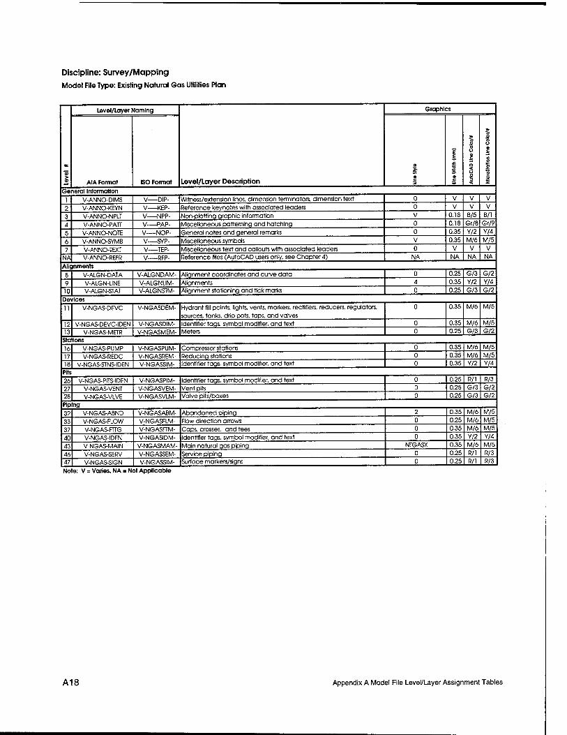
Discipline: Survey/Mapping
Model File Type: Existing Natural Gas Utilities Plan
at
Level/Layer Naming
Level/Layer Description
Graphics
AIA Format ISO Format
E e i ■a
Ö c
o o o a £ a < o o 3 <
5 o o o
c o o 2 u 2
General Information
1 V-ANNO-D1MS V DIP- Witness/extension lines, dimension terminators, dimension text 0 V V V
? V-ANNO-KEYN V KEP- Reference keynotes with associated leaders 0 V V V
3 V-ANNO-NPLT V NPP- Non-plotting graphic information V 0.18 B/5 B/l
4 V-ANNO-PATT V-—PAP- Miscellaneous patterning and hatching 0 0.18 Gr/8 Gr/9
S V-ANNO-NOTE V NOP- General notes and general remarks 0 0.35 Y/2 Y/4
6 V-ANNO-SYMB V SYP- Miscellaneous symbols V 0.35 M/6 M/5
7 V-ANNO-TEXT V TEP- Miscellaneous text and callouts with associated leaders 0 V V V
NA V-ANNO-REFR V—RFP- Reference files (AutoCAD users only, see Chapter 4) NA NA NA NA
Alignments
8 V-ALGN-DATA V-ALGNDAM- Alignment coordinates and curve data 0 0.25 G/3 G/2
9 V-ALGN-L1NE V-ALGNLIM- Alignments 4 0.35 Y/2 Y/4
10 V-ALGN-STAT V-ALGNSTM- Alignment stationing and tick marks 0 0.25 G/3 G/2
Devices
11 V-NGAS-DEVC V-NGASDEM- Hydrant fill points, lights, vents, markers, rectifiers, reducers, regulators,
sources, tanks, drip pots, taps, and valves
0 0.35 M/6 M/5
12 V-NGAS-DEVC-IDEN V-NGASDIM- Identifier tags, symbol modifier, and text 0 0.35 M/6 M/5
13 V-NGAS-METR V-NGASMEM- Meters 0 0.25 G/3 G/2
Stations
16 V-NGAS-PUMP V-NGASPUM- Compressor stations 0 0.35 M/6 M/5
17 V-NGAS-REDC V-NGASREM- Reducing stations 0 0.35 M/6 M/5
18 V-NGAS-STNS-IDEN V-NGASSIM- Identifier tags, symbol modifier, and text 0 0.35 Y/2 Y/4
Pits
26 V-NGAS-PITS-IDEN V-NGASPIM- Identifier tags, symbol modifier, and text 0 0.25 R/l R/3
27 V-NGAS-VENT V-NGASVEM- Vent pits 0 0.25 G/3 G/2
28 V-NGAS-VLVE V-NGASVLM- Valve pits/boxes 0 0.25 G/3 G/2
Piping 32 V-NGAS-ABND V-NGASABM- Abandoned piping 2 0.35 M/6 M/5
33 V-NGAS-FLOW V-NGASFLM- Flow direction arrows 0 0.25 M/6 M/5
37 V-NGAS-FTTG V-NGASFTM- Caps, crosses, and tees 0 0.35 M/6 M/5
40 V-NGAS-IDEN V-NGASIDM- Identifier tags, symbol modifier, and text 0 0.35 Y/2 Y/4
43 V-NGAS-MA1N V-NGASMAM- Main natural gas piping NTGASX 0.35 M/6 M/5
46 V-NGAS-SERV V-NGASSEM- Service piping 0 0.25 R/l R/3
47 V-NGAS-S1GN V-NGASSIM- Surface markers/signs 0 0.25 R/l R/3
Note: V = Varies, NA = Not Applicable
A18 Appendix A Model File Level/Layer Assignment Tables
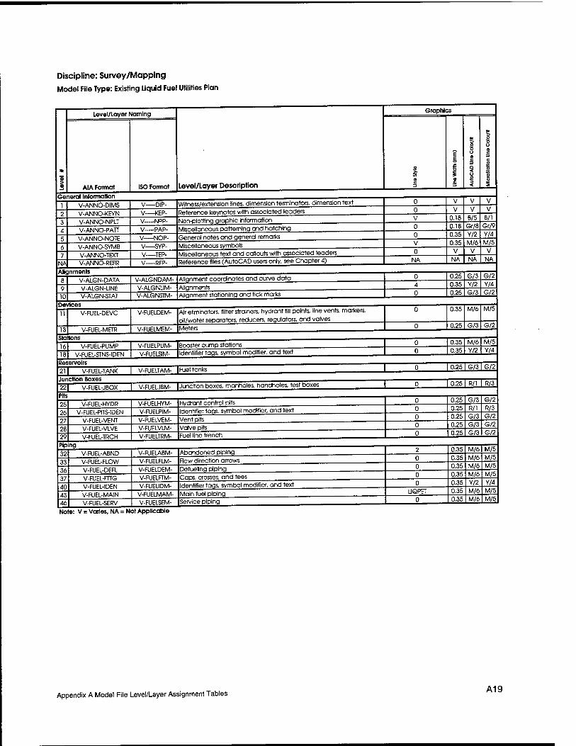
Discipline: Survey/Mapping Model File Type: Existing Liquid Fuel Utilities Plan
>
Go
Level/Layer Naming
Level/Layer Description
Graphics
A1A Format
loral Information
ISO Format
w O c
t £ £ 13 s 9
o o u o c
O < Ü o 3 <
o o o a c
| o K 2 u S
1 ?
V-ANNO-DIMS V-ANNO-KEYN
V DIP-
V—KEP-
Witness/extension lines, dimension terminators, dimension text
Reference keynotes with associated leaders
0
0
V
V
V
V
V V
1 V-ANNO-NPLT V NPP- Non-plottinq graphic information V a it* B/b B/l
4 V-ANNO-PATT V PAP- Miscellaneous patterning and hatching 0 U.IÖ
0 35
Gr/Ö
Y/2
Gr/9
Y/4 5
6
V-ANNO-NOTE V-ANNO-SYMB
V NOP- V SYP-
General notes and general remarks
Miscellaneous symbols V 0.35 V
M/6 V
M/5
V 7
NA
V-ANNO-TEXT V-ANNO-REFR
V—TEP-
V RFP-
Miscellaneous text and callouts with associated leaders Reference files (AutoCAD users only, see Chapter 4) NA NA NA NA
Alir nments R V-ALGN-DATA V-ALGNDAM- Alignment coordinates and curve data 0 U.25 G/3 G/2
9 V-ALGN-UNE V-ALGNL1M- Alignments 4 0.3b V/2 Y/4
10 V-ALGN-STAT V-ALGNSTM- Alignment stationing and tick marks 0 0.2b G/3 G/2
11
rices V-FUEL-DEVC V-FUELDEM-
V-FUELMEM-
Air eliminators, filter strainers, hydrant fill points, line vents, markers,
oil/water separators, reducers, regulators, and valves
Meters
0
0
0.3b
0.2b
M/6
G/3
M/5
G/2
Sta1
1ft
Bons
V-FUEL-PUMP V-FUELPUM- Booster pump stations 0 0.35 M/6 M/5
18 V-FUEL-STNS-IDEN V-FUELSIM- Identifier tags, symbol modifier, and text 0 U.35 Y/2 Y/4
211 V-FUEl-TANK I V-FUELTAM- |Fuel tanks 1 Ü 1 u.zo | wo | w
22 Pits
25
V-FUEL-JBOX
V-FUEL-HYDR
V-FUEUBM-
V-FUELHYM-
lJunction boxes, manholes, handholes, test boxes
Hydrant control pits
0
0
0
0.2b
0.2b 0.25
K/l
G/3
R/l
K/J
G/2
R/3 26 27 V-FUEL-VENT
V-FUEL-VLVE
V-FUELVEM-
V-FUELVLM-
Vent pits Valve pits
0 0
0.25 0.2b
G/3 G/3
G/2 G/2
?9 V-FUEL-TRCH V-FUELTRM- Fuel line trench 0 0.25 G/3 G/2
Pip ing
1? V-FUEL-ABND V-FUELABM- Abandoned piping 2 0.3b M/6 M/5
11 V-FUEL-FLOW V-FUELFLM- Flow direction arrows 0 U.3b M/6 M/5
16 V-FUEL-DEFL V-FUELDEM- Defueling piping 0 U.3b M/6 M/5
?7 V-FUEL-FTTG V-FUELFTM- Caps, crosses, and tees 0 0.3b M/6 M/5
40 V-FUEL-1DEN V-FUEUDM- Identifier taqs, symbol modifier, and text 0 0.35
0 35
Y/2 M/6
Y/4 M/b
43 46
V-FUEL-MAIN
V-FUEL-SERV
V-FUELMAM-
V-FUELSEM-
Main fuel piping Service piping 0 0.35 M/6 M/5
Note: V = Varies, NA = Not Applicable
Appendix A Model File Level/Layer Assignment Tables A19
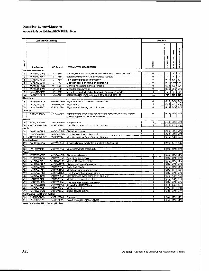
Discipline: Survey/Mapping
Model File Type: Existing HTCW Utilities Plan
® > 2
Level/Layer Naming
Level/Layer Description
Graphics
AIA Format ISO Format
E B £ s o
o o o a C
a < o o 3 <
4*
O O o o c
c O O g u 2
General Information
1 V-ANNO-DIMS V—DIP- Witness/extension lines, dimension terminators, dimension text 0 V V V
2 V-ANNO-KEYN V KEP- Reference keynotes with associated leaders 0 V V V
3 V-ANNO-NPLT V NPP- Non-plotting graphic information V 0.18 B/5 B/l
4 V-ANNO-PATT V PAP- Miscellaneous patterning and hatching 0 0.18 Gr/8 Gr/9
5 V-ANNO-NOTE V—NOP- General notes and general remarks 0 0.35 Y/2 Y/4
6 V-ANNO-SYMB V—SYP- Miscellaneous symbols V 0.35 M/6 M/5
7 V-ANNO-TEXT V—TEP- Miscellaneous text and callouts with associated leaders 0 V V V
NA V-ANNO-REFR V RFP- Reference files (AutoCAD users only, see Chapter 4) NA NA NA NA
Alignments
8 V-ALGN-DATA V-ALGNDAM- Alignment coordinates and curve data 0 0.25 G/3 G/2
9 V-ALGN-UNE V-ALGNUM- Alignments 4 0.35 Y/2 Y/4
10 V-ALGN-STAT V-ALGNSTM- Alignment stationing and tick marks 0 0.25 G/3 G/2
Devices
11 V-KTCW-DEVC V-HTCWDEM- Rigid anchors, anchor guides, rectifiers, reducers, markers, meters, pumps, regulators, tanks, and valves
0 0.35 M/6 M/5
Stations
16 V-HTCW-PUMP V-HTCWPUM- Pump stations 0 0.35 M/6 M/5
18 V-HTCW-STNS-1DEN V-HTCWSIM- Identifier tags, symbol modifier, and text 0 0.35 Y/2 Y/4 Plants
19 V-HTCW-CHLP V-HTCWCPM- Chilled water plant 0 0.35 M/6 M/5
20 V-HTCW-HTPP V-HTCWHPM- High temperature water plant 0 0.35 M/6 M/5
21 V-HTCW-PLNT-IDEN V-HTCWPiM- Identifier tags, symbol modifier, and text 0 0.35 Y/2 Y/4
Junction Boxes 22| V-HTCW-JBOX I V-HTCWJBM- function boxes, manholes, handholes, test boxes | 0 I 0.25 I R/l I R/3
Pits 25| V-HTCW-PITS | V-HTCWPTM- |Valve pits/vaults, steam pits I 0 I 0.251 G/31G/2
Piping
32 V-HTCW-ABND V-HTCWABM- Abandoned piping 2 0.35 M/6 M/5
33 V-HTCW-FLOW V-HTCWFLM- Flow direction arrows 0 0.25 G/3 G/2
34 V-HTCW-CHLL V-HTCWCHM- Main chilled water piping 0 0.35 M/6 M/5
35 V-HTCW-CHLS V-HTCWCSM- Chilled water service piping 0 0.25 G/3 G/2
37 V-HTCW-FnG V-HTCWFTM- Caps and flanges 0 0.35 M/6 M/5
38 V-HTCW-HTPL V-HTCWHTM- Main high temperature piping 0 0.25 R/l R/3
39 V-HTCW-HTPS V-HTCWHSM- High temperature service piping 0 0.25 G/3 G/2
40 V-HTCW-IDEN V-HTCWIDM- Identifier tags, symbol modifier, and text 0 0.35 Y/2 Y/4
41 V-HTCW-LTPL V-HTCWLTM- Main low temperature piping 0 0.35 Y/2 Y/4
42 V-KTCW-LTPS V-HTCWLSM- Low temperature service piping 0 0.25 G/3 G/2
45 V-HTCW-RTRN V-HTCWRTM- Return for all HTCW lines 0 0.18 B/5 B/l
48 V-HTCW-STML V-HTCWSTM- Main steam piping 0 0.25 R/l R/3 49 V-HTCW-STMS V-HTCWSSM- Steam service piping 0 0.25 G/3 G/2
Geothermal Heat Pump System
50 V-GTHP-EQPM V-GTHPEQM- Equipment 0 0.35 M/6 M/5
51 V-GTHP-PIPE V-GTHPPIM- Piping (includes fittings, valves) 0 0.35 M/6 M/5
Note: V = Varies, NA = Not Applicable
A20 Appendix A Model File Level/Layer Assignment Tables
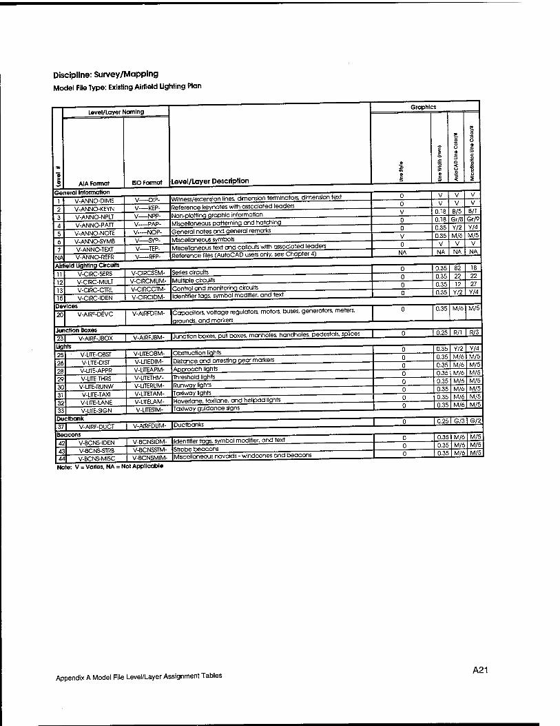
Discipline: Survey/Mapping Model File Type: Existing Airfield Lighting Plan
Level/Layer Naming
AIA Format General Information
ISO Format Level/Layer Description
NA
Devices
V-ANNO-D1MS V-ANNO-KEYN V-ANNO-NPLT V-ANNO-PATT V-ANNO-NOTE V-ANNO-SYMB V-ANNO-TEXT V-ANNO-REFR
Airfield Ughting Circuits
-DIP- -KEP-
y NPP- V—PAP- V—NOP- V SYP- V TEP- V—RFP-
Witness/extension lines, dimension terminators, dimension text Reference keynotes with associated leaders Non-plotting graphic information Miscellaneous patterning and hatching General notes and general remarks Miscellaneous symbols Miscellaneous text and callouts with associated leaders Reference files (AutoCAD users only, see Chapter 4)
12 13 15
V-CIRC-SERS V-CIRC-MULT V-CIRC-CTRL V-CIRC-IDEN
V-CIRCSEM- Series circuits V-CIRCMUM- V-CIRCCTM- V-CIRCIDM-
Multiple circuits Control and monitoring circuits Identifier togs, symbol modifier, and text
20 V-AIRF-DEVC
Junction Boxes
V-AIRFDEM- Capacitors, voltage regulators, motors, buses, generators, meters, grounds, and markers
23| V-AIRF-JBOX V-AIRFJBM- ljunction boxes, pull boxes, manholes, hondholes, pedestals, splices |
Lights 25 26 28 29 30
Ductbank 37T V-AIRF-DUCT"
32 33
V-UTE-OBST V-UIE-DIST
V-UTE-APPR V-LITE-THRS
V-UTE-RUNW V-UTE-TAXI V-UTE-LANE V-LiTE-SIGN
V-ÜTEOBM- V-UTEDIM-
Obstruction lights Distance and arresting gear markers
V-UTEAPM- Approach lights V-UTETHM- V-lfTERUM- V-UTETAM- V-UTELAM- V-UTESIM-
Threshold lights Runway lights Taxiwoy lights Hoverlane, taxilane, and helipad lights Taxiway guidance signs
V-AIRFDUM- IDuctbanks
Beacons 42 43 44
V-BCNS-IDEN V-BCNS-STRB V-BCNS-MISC
V-BCNSIDM- Identifier tags, symbol modifier, and text V-BCNSSTM- V-BCNSMIM-
Strobe beacons Miscellaneous navoids - windcones and beacons
Note: V = Varies, NA = Not Applicable
Graphics
NA
0.18 0.18 0.35 0.35
NA
B/5 Gr/8 Y/2 M/6
NA
B/l Gr/9 Y/4 M/5
V NA
0.35 0.35 0.35 0.35
82 22 12
Y/2 27 Y/4
0.35 M/6 M/5
I 0.25 I R/l I R/3
0.35 0.35 0.35 0.35 0.35 0.35 0.35 0.35
Y/2 M/6 M/6 M/6 M/6 M/6 M/6 M/6
Y/4 M/5 M/5 M/5 M/5 M/5 M/5 M/5
I 0.25 I G/3 I G/2
0.35 0.35 0.35
M/6 M/6 M/6
M/5 M/5 M/5
Appendix A Model File Level/Layer Assignment Tables A21
Discipline: Survey/Mapping
Model File Type: Existing Profiles
> _i
Level/Layer Naming
Level/Layer Description
Graphics
AIA Format ISO Format O c
E E
S a c
o o o a c a < u o 3 <
5 o o a c c o
2 o S
General Information
1 V-ANNO-DIMS V—DIP- Witness/extension lines, dimension terminators, dimension text 0 V V V 2 V-ANNO-KEYN V—KEP- Reference keynotes with associated leaders 0 V V V 3 V-ANNO-NPLT V NPP- Non-plotting graphic Information V 0.18 B/5 B/l 4 V-ANNO-PATT V PAP- Miscellaneous patterning and hatching 0 0.18 Gr/8 Gr/9 5 V-ANNO-NOTE V NOP- General notes and general remarks 0 0.35 Y/2 Y/4 6 V-ANNO-SYMB V—SYP- Miscellaneous symbols V 0.35 M/6 M/5 7 V-ANNO-TEXT V TEP- Miscellaneous text and callouts with associated leaders 0 V V V
NA V-ANNO-REFR V RFP- Reference files (AutoCAD users only, see Chapter 4) NA NA NA NA Crossing Elements - Use symbology from previous model files
Grade Linework
41 V-GRAD-FNSH V-GRADFNM- Finished grade 0 0.50 C/4 C/7 44 V-GRAD-EXST V-GRADEXM- Existing grade, ground line 3 0.35 M/6 M/5 Grid Lines
48 V-GRID-MAJR V-GRIDMAM- Major grid lines 0 0.25 R/l R/3 49 V-GRID-MINR V-GRIDMIM- Minor grid lines 1 0.18 Gr/8 Gr/9 50 V-GRID-FRAM V-GRIDFRM- Frame 0 0.50 C/4 C/7 51 V-GRID-TEXT V-GRIDTEM- Border text, annotation 0 0.35 Y/2 Y/4 Note: V = Varies, NA = Not Applicable
A22 Appendix A Model File Level/Layer Assignment Tables
Discipline: Survey/Mapping Model File Type: Existing X-Sections
1
Level/Layer Naming
Level/Layer Description
Graphics
AIA Format ISO Format «
t g £
© c
o ■5 O o C
o < Ü O 3 <
3*
o o u a
o 3= a o u 2
1 ?
V-ANNO-DIMS V-ANNO-KEYN
V-—DIP-
V KEP-
Witness/extension lines, dimension terminators, dimension text
Reference keynotes with associated leaders
0
0
V
V
V
V
V
V
? V-ANNO-NPLT V NPP- Non-plottina araDhic information V U. lb B/5 B/l
4 V-ANNO-PATT V PAP- Miscellaneous patterning and hatching 0 a IB Gr/B Gr/9
S V-ANNO-NOTE V NOP- General notes and general remarks 0 U.3b Y/2 Y/4
6 V-ANNO-SYMB V SYP- Miscellaneous symbols V U.3b M/6 M/5
7 V-ANNO-TEXT V TEP- Miscellaneous text and callouts with associated leaders 0 V V V
NA V-ANNO-REFR V RFP- Reference files (AutoCAD users only, see Chapter 4) NA NA NA NA
Crnssina Elements - Use svmboloqv from previous model files __
3"i V-SECT-IDEN V-SECTIDM- Component identification numbers 0 0.3b Y/2 Y/4
,Vi V-SECT-MBND V-SECTMBM- Material beyond section cut 0 Ü. IB B/b B/l
^7 V-SECT-MCUT V-SECTMCM- Material cut by section 0 u.bu C/4 C//
38 V-SECT-PATT V-SECTPAM- Textures and hatch patterns 0 U.IB fcJr/b Gr/9
Grc ide Linework
.11 V-GRAD-FNSH V-GRADFNM- Finished arade 0 0.50 C/4 (J//
44 V-GRAD-EXST V-GRADEXM- Existing grade, ground line 3 0.35 M/6 M/5
Gn
4«
d Lines V-GRID-MAJR V-GR1DMAM- Major grid lines 0 0.25 R/l R/3
49 V-GRID-MINR V-GRIDMIM- Minor grid lines 1 a 18 <=Jr/B Gr/9
■in V-GRID-FRAM V-GRIDFRM- Frame 0 0.50 C/4 C/7
51 V-GRID-TEXT V-GRIDTEM- Border text, annotation 0 0.3b Y/2 Y/4
Note: V = Varies, NA = Not Applicable
Appendix A Model File Level/Layer Assignment Tables A23

Discipline: Geotechnical
Model File Type: Boring Location Plan
*
I
Level/Layer Naming
Level/Layer Description
Graphics
AIA Format ISO Format a
E e
5 a c
5 o o c a < o o 1
o o u o c c o 1 o
General Information
1 B-ANNO-DIMS B DIP- Witness/extension lines, dimension terminators, dimension text 0 V V V 2 B-ANNO-KEYN B KEP- Reference keynotes with associated leaders 0 V V V 3 B-ANNO-NPLT B NPP- Non-plotting graphic information V 0.18 B/5 B/l 4 B-ANNO-PATT B PAP- Miscellaneous patterning and hatching 0 0.18 Gr/8 Gr/9
5 B-ANNO-NOTE B NOP- General notes and general remarks 0 0.35 Y/2 Y/4
6 B-ANNO-SYMB B—SYP- Miscellaneous symbols V 0.35 M/6 M/5 7 B-ANNO-TEXT B—TEP- Miscellaneous text and callouts with associated leaders 0 V V V
NA B-ANNO-REFR B RFP- Reference files (AutoCAD users only, see Chapter 4) NA NA NA NA Borings/Perc Holes
12 B-BORE-HOLE B-BOREHOM- Bore/perc hole locations 0 0.35 Y/2 Y/4 13 B-BORE-IDEN B-BOREIDM- Bore/perc hole numbers 0 0.35 Y/2 Y/4 Note: V = Varies, NA = Not Applicable
A24 Appendix A Model File Level/Layer Assignment Tables
Discipline: Geotechnical Model File Type: Boring Log
General Information
Level/Layer Naming
AIA Format BO Format
Graphics
Level/Layer Description
B-ANNO-DIMS B-ANNO-KEYN B-ANNO-NPLT B-ANNO-PATT B-ANNO-NOTE B-ANNO-SYMB B-ANNO-TEXT B-ANNO-REFR
Borings/Perc Holes
--DIP- B KEP- Reference keynotes with associated leaders B—NPP- Non-plotting graphic Information B—PAP- B—NOP- B—SYP- B TEP- B RFP-
Witness/extension lines, dimension terminators, dimension text
0.18 B/5 B/l
Miscellaneous patterning and hatching 0.18 Gr/8 Gr/9
General notes and general remarks 0.35
Miscellaneous symbols 0.35 Y/2 M/6
Y/4 M/5
Miscellaneous text and callouts with associated leaders Reference files (AutoCAD users only, see Chapter 4) NA NA NA NA
10 11 12 13 14 15
B-BORE-ELEV B-BORE-FDTA B-BORE-HOLE B-BORE-IDEN B-BORE-LDTA B-BORE-PATT
B-BOREELM- Boring elevations B-BOREFDM- Field data B-BOREHOM- B-BOREIDM- B-BORELDM- B-BOREPAM-
0.25 G/3 G/2 0.25 G/3 G/2
Bore/perc hole number 0.35 Y/2 Y/4
Component identification numbers Laboratory data
0.35 0.25
Y/2 R/l
Soil/rock patterns 0.18 Gr/8
Y/4 R/3 Gr/9
Note: V = Varies, NA = Not Applicable
Appendix A Model File Level/Layer Assignment Tables A25
Discipline: Civil
Model File Type: Site Plan
* ©
Level/Layer Naming
Level/Layer Description
Graphics
AIA Format ISO Format a
£ E £ 13
©
* o o o a c o < Ü
<
o o o « C =1 C o 3= a o
I General Information
1 C-ANNO-DIMS C—DIP- Witness/extension lines, dimension terminators, dimension text 0 V V V 2 C-ANNO-KEYN C KEP- Reference keynotes with associated leaders 0 V V V 3 C-ANNO-NPLT C NPP- Non-plotting graphic information V 0.18 B/5 B/l 4 C-ANNO-PATT C PAP- Miscellaneous patterning and hatching 0 0.18 Gr/8 Gr/9 5 C-ANNO-NOTE C NOP- General notes and general remarks 0 0.35 Y/2 Y/4 6 C-ANNO-SYMB C SYP- Miscellaneous symbols V 0.35 M/6 M/5 7 C-ANNO-TEXT C—TEP- Miscellaneous text and callouts with associated leaders 0 V V V
NA C-ANNO-REFR C RFP- Reference files (AutoCAD users only, see Chapter 4) NA NA NA NA Alignments
8 C-ALGN-DATA C-AIGNDAM- Alignment coordinates and curve data 0 0.25 G/3 G/2 9 C-ALGN-UNE C-ALGNUM- Alignments 4 0.35 Y/2 Y/4 10 C-ALGN-STAT C-ALGNSTM- Alignment stationing and tick marks 0 0.25 G/3 G/2
Buildings and Structures
11 C-BLDG-OTLN C-BLDGOTM- Buildings and other structures 0 0.70 W/7 W/0 12 C-BLDG-IDEN C-BLDGIDM- Building and other stucture annotation 0 0.35 Y/2 Y/4
Site Improvement
13 C-SITE-FENC C-SITEFEM- Fences and handrails 0, FENCE 0.35 M/6 M/5 14 C-SITE-FENC-IDEN C-SITEFIM- Fence, handrail, ramp, sign, and trail annotation 0 0.35 M/6 M/5 15 C-SITE-STRC C-SITESRM- Structures (bridges, sheds, foundation pads, footings, etc.) 0 0.35 22 22 16 C-SITE-IDEN C-SITEIDM- Site improvement annotation 0 0.35 M/6 M/5 17 C-SITE-IMPR C-SITEIMM- Site improvements (channel or levee features) 0 0.50 C/4 C/7 18 C-SITE-EROS C-SITEERM- Riprap, revetments/stone protection, breakwaters, dikes, jetties, and
drains 0 0.25 R/l R/3
19 C-SITE-EROS-IDEN C-SITEEIM- Riprap, revetment/stone protection, breakwater, dike, jetty, and drain annotation
0 0.35 12 27
20 C-SITE-STRS C-SITESTM- Stairs and ramps 0 0.35 M/6 M/5 21 C-SITE-WALK C-SITEWAM- Walks, trails and bicycle paths V 0.35 Y/2 Y/4 Property
25 C-PROP-ESMT C-PROPESM- Easements 3 0.70 84 34 26 C-PROP-CONS C-PROPCOM- Construction limits/controls, staging area 11 0.70 W/7 W/0 27 C-PROP-RWAY C-PROPRWM- Right of ways RTOFWY 0.70 W/7 W/0 28 C-PROP-IDEN C-PROPIDM- Property annotation 0 0.35 M/6 M/5
Storm Drainage (for more detailed storm drainage, use the Civil - Storm Drainage model file)
30 C-STRM-STRC C-STRMSTM- Storm drainage, headwalls, inlets, manholes, culverts, and drainage structures
0, STRAF 0.50 C/4 C/7
31 C-STRM-IDEN C-STRMIDM- Storm drainage, headwall. Inlet, manhole, culvert, and drainage structure annotation
0 0.35 Y/2 Y/4
Pavements/Transportation (for more detailed transportation, use the Civil - Transportation Site Plan model file)
34 C-PVMT-ROAD C-PVMTROM- Roads, parking lots, railroads, airfield pavements 0. RAILRD 0.35 Y/2 Y/4 35 C-PVMT-IDEN C-PVMTIDM- Road, parking lot, railroad, airfield pavement annotation 0 0.35 Y/2 Y/4 36 C-PVMT-PATT C-PVMTPAM- Joint patterns, text and dimensions 0 0.35 Y/2 Y/4 37 C-PVMT-MRKG C-PVMTMRM- Pavement markings and signs 0 0.35 Y/2 Y/4 Secondary Alignments
38 C-ALGN-SECD C-ALGNSCM- Secondary alignments 0 0.25 G/3 G/2 39 C-ALGN-SECD-IDEN C-ALGNSIM- Alignment stationing and tick marks 0 0.35 82 18 Topography
40 C-TOPO-COOR C-TOPOCOM- Coordinate grid ticks and text 0 0.35 122 23 41 C-TOPO-MAJR-IDEN C-TOPOMAM- Major contours - annotation 0 0.35 Y/2 Y/4 42 C-TOPO-MAJR C-TOPOMJM- Major contours 0 0.35 Y/2 Y/4 43 C-TOPO-MINR-IDEN C-TOPOMIM- Minor contours - annotation 0 0.25 G/3 G/2 44 C-TOPO-MINR C-TOPOMNM- Minor contours 0 0.25 G/3 G/2 46 C-TOPO-SLOP-IDEN C-TOPOSLM- Cut/fill slope, top/toe slope annotation 0 0.35 Y/2 Y/4 47 C-TOPO-SLOP-FILL C-TOPOSFM- Cut/fill slopes 0 0.35 Y/2 Y/4 48 C-TOPO-SPOT C-TOPOSPM- Spot elevations 0 0.35 Y/2 Y/4 49 C-TOPO-SLOP-TOPT C-TOPOSTM- Top/toe slopes 0 0.35 M/6 M/5
A26 Appendix A Model File Level/Layer Assignment Tables
Discipline: Civil Model File Type: Site Plan
Demolition (used only in creating Existing/Demolition model files)
56 57 58
C-STAT-DEMO-PHS1 C-STAT-DEMO-PHS2 C-STAT-DEMO-PHS3
--M-D—1 -M-D—2 -M-D—3
Demolition - phase 1 Demolition - phase 2 Demolition - phase 3
0.50 0.50 0.50
203 83 163
45 42 41
Note: V = Varies, NA = Not Applicable
Appendix A Model File Level/Layer Assignment Tables A27
Discipline: Civil Model File Type: Grading Plan
*
Level/Layer Naming Graphics
AIA Format ISO Format Level/Layer Description c
? E I ■o
* 5 o ü » c
o < o o 5
* o o O o c c o 3= o 2 t> 2
General Information 1 C-ANNO-DIMS C—DIP- Witness/extension lines, dimension terminators, dimension text 0 V V V
2 C-ANNO-KEYN C KEP- Reference keynotes with associated leaders 0 V V V
3 C-ANNO-NPLT C NPP- Non-plotting graphic information V 0.18 B/5 B/l
4 C-ANNO-PATT C PAP- Miscellaneous patterning, cross-hatching, poche 0 0.18 Gr/8 Gr/9
5 C-ANNO-NOTE C NOP- General notes and general remarks 0 0.35 Y/2 Y/4
6 C-ANNO-SYMB C SYP- Miscellaneous symbols V 0.35 M/6 M/5
7 C-ANNO-TEXT C TEP- Miscellaneous text and callouts with associated leaders 0 V V V NA C-ANNO-REFR C RFP- Reference files (AutoCAD users only, see Chapter 4) NA NA NA NA
Alignments 8 C-ALGN-DATA C-ALGNDAM- Alignment coordinates and curve data 0 0.25 G/3 G/2
9 C-ALGN-UNE C-AIGNUM- Alignments 4 0.35 Y/2 Y/4
10 C-ALGN-STAT C-ALGNSTM- Alignment stationing and tick marks 0 0.25 G/3 G/2 Borrow Areas 21 C-BORW-LINE C-BORWLNM- Borrow/Spoil area 2 0.35 Y/2 Y/4 22 C-BORW-IDEN C-BORWIDM- Borrow/Spoil area annotation 0 0.35 Y/2 Y/4
Topography 40 C-TOPO-COOR C-TOPOCOM- Coordinate grid ticks and text 0 0.35 122 23
41 C-TOPO-MAJR-IDEN C-TOPOMAM- Major contours - annotation 0 0.35 Y/2 Y/4
4? C-TOPO-MAJR C-TOPOMJM- Major contours 0 0.35 Y/2 Y/4
43 C-TOPO-MINR-IDEN C-TOPOMIM- Minor contours - annotation 0 0.25 G/3 G/2
44 C-TOPO-MINR C-TOPOMNM- Minor contours 0 0.25 G/3 G/2
46 C-TOPO-SLOP-IDEN C-TOPOSIM- Cut/fill slope, top/toe slope annotation 0 0.35 Y/2 Y/4
47 C-TOPO-SLOP-FILL C-TOPOSFM- Cut/fill slopes 0 0.35 Y/2 Y/4
48 C-TOPO-SPOT C-TOPOSPM- Spot elevations 0 0.35 Y/2 Y/4
49 C-TOPO-SLOP-TOPT C-TOPOSTM- Top/toe slopes 0 0.35 M/6 M/5
50 C-TOPO-BKLN C-TOPOBKM- Breaklines 4 0.70 W/7 W/0
51 C-TOPO-DTMT C-TOPODTM- DTM triangles 0 0.35 22 22
52 C-TOPO-DTMP C-TOPODPM- DTM points 0 0.35 M/6 M/5
Demolition (used only in creating Existing/Demolition model files) So C-STAT-DEMO-PHS1 C M-D—1 Demolition - phase 1 0 0.50 203 45
57 C-STAT-DEMO-PHS2 C——M-D—2 Demolition - phase 2 0 0.50 83 42 58 C-STAT-DEMO-PHS3 C M-D—3 Demolition - phase 3 0 0.50 163 41 Note: V = Varies, NA = Not Applicable
A28 Appendix A Model File Level/Layer Assignment Tables
Discipline: Civil Model File Type: Dredging Plan
General Information
level/layer Naming
AIA Format ISO Format Level/Layer Description
NA
C-ANNO-DIMS C-ANNO-KEYN C-ANNO-NPLT C-ANNO-PATT C-ANNO-NOTE C-ANNO-SYMB C-ANNO-TEXT C-ANNO-REFR
C DIP- -KEP- Reference keynotes with associated leaders -NPP- Non-plotting graphic information -PAP- -NOP-
C—SYP- C—TEP-
-RFP-
Witness/extension lines, dimension terminators, dimension text
Miscellaneous patterning and hatching General notes and general remarks Miscellaneous symbols Miscellaneous text and callouts with associated leaders Reference files (AutoCAD users only, see Chapter 4)
Survey Lines
10
C-SURV-DATA C-SURV-LINE C-SURV-IDEN
Structures
C-SURVDAM- C-SURVUM-
Survey data (benchmarks and horizontal control points or monuments)
C-SURVIDM- Survey, baseline, and control lines Survey, baseline, and control line annotation
12 C-STRC-OTLN C-STRC-IDEN
Channels
C-STRCOTM- C-STRCIDM-
Bridges, piers, breakwaters, docks, floats, etc, - outlines Bridges, piers, breakwaters, docks, floats, etc. - annotation
14 15 16 17 18 19 20 21
C-CHAN-UMT C-CHAN-IDEN C-CHAN-DACL
C-CHAN-DACL-IDEN C-CHAN-CNTR
C-CHAN-CNTR-IDEN C-CHAN-AIDS C-CHAN-TURN
C-CHANLIM- C-CHANIDM- C-CHANDAM- C-CHANDIM- C-CHANCNM- C-CHANCIM- C-CHANAIM- C-CHANTUM-
Channel limits, anchorages, turning basins, disposal areas, etc Channel limits, anchorages, turning basins, disposal areas, etc. - annota De-authorized channel limits, anchorages, etc De-authorized channel limits, anchorages, etc. - annotation Channel centerline and survey report lines Channel centerline and survey report lines - annotation Navigation aids and text Turning points
Dredging 25 26 Topography
C-DRED-UMT C-DRED-OHWM
C-DREDUM- C-DREDOHM-
Dredge limit lines Ordinary high water marks
39 40 41 42 43 44 45 49
C-TOPO-BORE C-TOPO-COOR
C-TOPO-MAJR-IDEN C-TOPO-MAJR
C-TOPO-MINR-IDEN C-TOPO-MINR C-TOPO-SHOR C-TOPO-SOUN
C-TOPOBOM- Boring locations C-TOPOCOM- Coordinate grid ticks and text C-TOPOMAM- C-TOPOMJM- C-TOPOMIM- C-TOPOMNM- C-TOPOSHM- C-TOPOSOM-
Major contours - annotation Major contours Minor contours - annotation Minor contours Shorelines, land features, and references Soundings
Demolition (used only in creating Existing/Demolition model files)
56 57 58
C-STAT-DEMO-PHS1 C-STAT-DEMO-PHS2 C-STAT-DEMO-PHS3
-M-D—1 Demolition - phase 1 -M-D—-2 -M-D—3
Note: V = Varies, NA = Not Applicable
Demolition - phase 2 Demolition - phase 3
Graphics
NA
0.18 B/5 B/l 0.18 Gr/8 Gr/9 0.35 0.35
Y/2 M/6
NA NA
Y/4 M/5 V
NA
0.35 M/6 0.50 C/4
M/5 C/7
0.35 M/6 M/5
0.50 C/4 0.35 Y/2
0.35 M/6 0.35 M/6 0.25 G/3 0.25 0.18
G/3 B/5
0.18 B/5 0.35 Y/2 0.35 Y/2
0.50 C/4 0.35 Y/2
0.35 M/6 0.35 122 0.35 Y/2 0.35 Y/2 0.25 0.25
G/3 G/3
0.50 0.18
0.50 203 0.50 83 0.50 163
C/7 Y/4
M/5 M/5 G/2 G/2 B/l B/l
C/4 150
Y/4 Y/4
C/7 Y/4
M/5 23 Y/4 Y/4 G/2 G/2 C/7 40
45 42 41
Appendix A Model File Level/Layer Assignment Tables A29
Discipline: Civil
Model File Type: Transportation Site Plan
* > 3
Level/Layer Naming
Level/Layer Description
Graphics
AIA Format ISO Format a c
£ e
o o Ü ft C
a < o
<
o o u o _c
o □ g u 2
General Information
1 C-ANNO-DIMS C DIP- Witness/extension lines, dimension terminators, dimension text 0 V V V
2 C-ANNO-KEYN C KEP- Reference keynotes with associated leaders 0 V V V
3 C-ANNO-NPLT C NPP- Non-plotting graphic information V 0.18 B/5 B/l 4 C-ANNO-PATT C PAP- Miscellaneous patterning and hatching 0 0.18 Gr/8 Gr/9 5 C-ANNO-NOTE C NOP- General notes and general remarks 0 0.35 Y/2 Y/4 6 C-ANNO-SYMB C SYP- Miscellaneous symbols V 0.35 M/6 M/5 7 C-ANNO-TEXT C TEP- Miscellaneous text and callouts with associated leaders 0 V V V
NA C-ANNO-REFR C RFP- Reference files (AutoCAD users only, see Chapter 4) NA NA NA NA Alignments
8 C-ALGN-DATA C-ALGNDAM- Alignment coordinates and curve data 0 0.25 G/3 G/2 9 C-ALGN-UNE C-ALGNUM- Alignments 4 0.35 Y/2 Y/4 10 C-ALGN-STAT C-ALGNSTM- Alignment stationing and tick marks 0 0.25 G/3 G/2 Major Roads
11 C-ROAD-CNTR-IDEN C-ROADCIM- Centerline annotation 0 0.35 M/6 M/5 12 C-ROAD-CNTR C-ROADCTM- Centerlines 7 0.25 R/l R/3 13 C-ROAD-CURB C-ROADCUM- Curbs 0 0.35 M/6 M/5 14 C-ROAD-GRAL C-ROADGRM- Guardrails 0 0.35 M/6 M/5 15 C-ROAD-IDEN C-ROADIDM- Road, curb, and guardrail annotation 0 0.35 M/6 M/5 16 C-ROAD-OTLN C-ROADOTM- Roads 0 0.50 C/4 C/7 Parking Lots and Minor Roads
21 C-PKNG-CARS C-PKNGCAM- Graphic illustration of cars 0 0.35 Y/2 Y/4 22 C-PKNG-CNTR-IDEN C-PKNGCIM- Centerline annotation 0 0.35 M/6 M/5 23 C-PKNG-CNTR C-PKNGCTM- Centerlines 7 0.25 R/l R/3 24 C-PKNG-CURB C-PKNGCUM- Curbs and gutters 0 0.25 G/3 G/2 25 C-PKNG-DRAN C-PKNGDRM- Parking lot drainage slope indications 0 0.25 R/l R/3 26 C-PKNG-IDEN C-PKNGIDM- Parking lot. minor road, and curb annotation 0 0.35 M/6 M/5 27 C-PKNG-FIXT C-PKNGFIM- Parking lot fixtures (e.g.. wheel stops, parking meters) 0 0.25 91 106 28 C-PKNG-OTLN C-PKNGOTM- Parking lots and minor roads 0 0.50 C/4 C/7 Railroads
32 C-RA1L-EQPM C-RAILEQM- Railroad equipment (e.g.. gates, signals) 0 0.25 91 106 33 C-RA1L-CNTR-IDEN C-RA1LCIM- Centerline annotation 0 0.35 M/6 M/5 34 C-RAIL-CNTR C-RAILCTM- Centerlines 7 0.25 R/l R/3 35 C-RAIL-IDEN C-RAIUDM- Railroad - annotation 0 0.35 M/6 M/5 36 C-RA1L-TRAK C-RAILTRM- Railroads 0 0.35 Y/2 Y/4 Signage and Pavement Markings
37 C-PVMT-MRKG C-PVMTMRM- Pavement markings and traffic signs 0 0.35 Y/2 Y/4 38 C-PVMT-SIGN C-PVMTSIM- Other signs 0 0.35 Y/2 Y/4 Pavement Types
41 C-PVMT-ASPH C-PVMTASM- Pavement pattern - asphalt 0 0.18 Gr/8 Gr/9 42 C-PVMT-CONC C-PVMTCOM- Pavement pattern - concrete 0 0.18 Gr/8 Gr/9 43 C-PVMT-GRVL C-PVMTGRM- Pavement pattern - gravel 0 0.18 Gr/8 Gr/9
Demolition (used only in creating Existing/Demolition model files)
56 C-STAT-DEMO-PHS1 C M-D—1 Demolition - phase 1 0 0.50 203 45 57 C-STAT-DEMO-PHS2 C M-D—2 Demolition - phase 2 0 0.50 83 42 58 C-STAT-DEMO-PHS3 C M-D—3 Demolition - phase 3 0 0.50 163 41 Note: V = Varies, NA = Not Applicable
A30 Appendix A Model File Level/Layer Assignment Tables
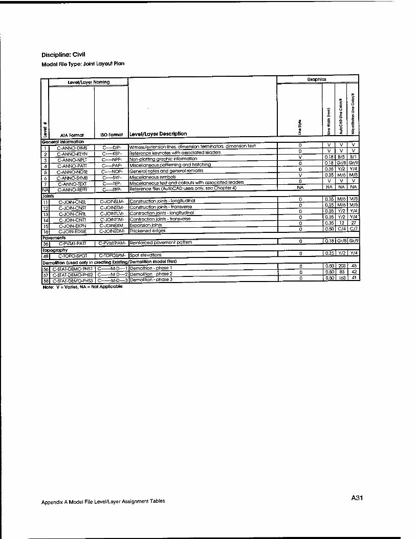
Discipline: Civil Model File Type: Joint Layout Plan
General Information
Level/layer Naming
AIA Format ISO Format Level/Layer Description
C-ANNO-DIMS C-ANNO-KEYN C-ANNO-NPLT C-ANNO-PATT C-ANNO-NOTE C-ANNO-SYMB C-ANNO-TEXT
NA C-ANNO-REFR
-DIP- -KEP- -NPP- -PAP- -NOP- -SYP-
C TEP- -RFP-
Witness/extension lines, dimension terminators, dimension text Reference keynotes with associated leaders Non-plotting graphic information Miscellaneous patterning ond hatching General notes and general remarks Miscellaneous symbols Miscellaneous text and callouts with associated leaders Reference files (AutoCAD users only, see Chapter 4)
Joints
12 13 14 15 16
C-JOIN-CNSL C-JOIN-CNST C-JOIN-CNTL C-JOIN-CNTT C-JOIN-EXPN C-JOIN-EDGE
C-JOINSLM- C-JOINSTM- C-JOINTLM- C-JOINTTM- C-JOINEXM- C-JOINEDM-
Construction joints - longitudinal Construction joints - transverse Contraction joints - longitudinal Contraction joints - transverse Expansion joints Thickened edges
Pavements 36 C-PVMT-PATT C-PVMTPAM- I Reinforced pavement pattern
Topography
Graphics
NA
481 C-TOPO-SPOT | C-TOPOSPM- |Spot elevations Demolition (used only in creating Existing/Demolition model files)
56 57 58
C-STAT-DEMO-PHS1 C-STAT-DEMO-PHS2 C-STAT-DEMOPHS3
-M-D—1 -M-D—-2 -M-D—3
Demolition - phase 1 Demolition - phase 2 Demolition - phase 3
Note: V = Varies, NA = Not Applicable
0.18 B/5 B/l 0.18 0.35
Gr/8 Y/2
0.35 M/6
Gr/9 Y/4 M/5
NA NA V
NA
0.35 M/6 M/5 0.35 M/6 M/5 0.35 0.35
Y/2 Y/2
0.35 12
Y/4 Y/4 27
0.50 C/4 C/7
I 0.18 I Gr/81 Gr/9
I 0.35 1 Y/2 I Y~
0.50 203 0.50 83 0,50 163
45 42 41
Appendix A Model File Level/Layer Assignment Tables A31
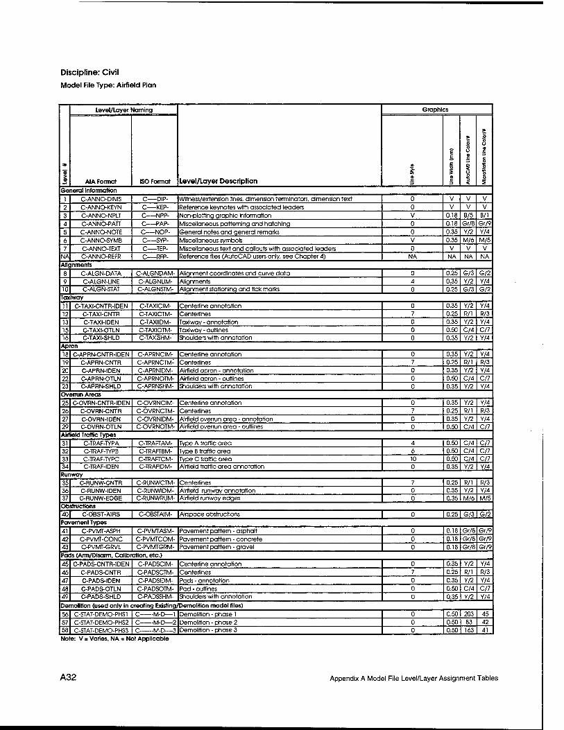
Discipline: Civil
Model File Type: Airfield Plan
a
3
Level/Layer Naming
Level/Layer Description
Graphics
AIA Format ISO Format c
£ E £
a c
o 8 9 C
O
s <
* o o o a
c o c 2 u S
General Information
1 C-ANNO-DIMS C—DIP- Witness/extension lines, dimension terminators, dimension text 0 V V V
2 C-ANNO-KEYN C KEP- Reference keynotes with associated leaders 0 V V V
3 C-ANNO-NPLT C NPP- Non-plotting graphic information V 0.18 B/5 B/l
4 C-ANNO-PATT C PAP- Miscellaneous patterning and hatching 0 0.18 Gr/8 Gr/9
5 C-ANNO-NOTE C NOP- General notes and general remarks 0 0.35 Y/2 Y/4
6 C-ANNO-SYMB C SYP- Miscellaneous symbols V 0.35 M/6 M/5
7 C-ANNO-TEXT C TEP- Miscellaneous text and callouts with associated leaders 0 V V V
NA C-ANNO-REFR C RFP- Reference files (AutoCAD users only, see Chapter 4) NA NA NA NA
Alignments
8 C-ALGN-DATA C-ALGNDAM- Alignment coordinates and curve data 0 0.25 G/3 G/2
9 C-ALGN-UNE C-ALGNUM- Alignments 4 0.35 Y/2 Y/4
10 C-ALGN-STAT C-ALGNSTM- Alignment stationing and tick marks 0 0.25 G/3 G/2
Taxiway
11 C-TAXI-CNTR-IDEN C-TAXICIM- Centerline annotation 0 0.35 Y/2 Y/4
12 C-TAXI-CNTR C-TAXICTM- Centerfines 7 0.25 R/l R/3
13 C-TAXI-IDEN C-TAXTIDM- Taxiway - annotation 0 0.35 Y/2 Y/4
15 C-TAXI-OTLN C-TAXTOTM- Taxiway - outlines 0 0.50 C/4 C/7
16 C-TAXI-SHLD C-TAXISHM- Shoulders with annotation 0 0.35 Y/2 Y/4
Apron
18 C-APRN-CNTR-IDENj C-APRNCIM- Centerline annotation 0 0.35 Y/2 Y/4
19 C-APRN-CNTR C-APRNCTM- Centerlines 7 0.25 R/l R/3
20 C-APRN-IDEN C-APRNIDM- Airfield apron - annotation 0 0.35 Y/2 Y/4
22 C-APRN-OTLN C-APRNOTM- Airfield apron - outlines 0 0.50 C/4 C/7
23 C-APRN-SHLD C-APRNSHM- Shoulders with annotation 0 0.35 Y/2 Y/4
Overrun Areas
25 C-OVRN-CNTR-IDEN C-OVRNCIM- Centerline annotation 0 0.35 Y/2 Y/4
26 C-OVRN-CNTR C-OVRNCTM- Centerlines 7 0.25 R/l R/3
27 C-OVRN-IDEN C-OVRNIDM- Airfield overrun area - annotation 0 0.35 Y/2 Y/4
29 C-OVRN-OTLN C-OVRNOTM- Airfield overrun area - outlines 0 0.50 C/4 C/7
Airfield Traffic Types
31 C-TRAF-TYPA C-TRAFTAM- Type A traffic area 4 0.50 C/4 C/7
32 C-TRAF-TYPB C-TRAFTBM- Type B traffic area 6 0.50 C/4 C/7
33 C-TRAF-TYPC C-TRAFTCM- Type C traffic area 10 0.50 C/4 C/7 34 C-TRAF-IDEN C-TRAFIDM- Airfield traffic area annotation 0 0.35 Y/2 Y/4 Runway
35 C-RUMW-CNTR C-RUNWCTM- Centerlines 7 0.25 R/l R/3
36 C-RUNW-IDEN C-RUNWIDM- Airfield runway annotation 0 0.35 Y/2 Y/4
37 C-RUNW-EDGE C-RUNWRUM- Airfield runway edges 0 0.35 M/6 M/5 Obstructions 40| C-OBST-AIRS | C-OBSTAIM- |Airspace obstructions | 0 I 0.251 G/31G/2
Pavement Types
41 C-PVMT-ASPH C-PVMTASM- Pavement pattern - asphalt 0 0.18 Gr/8 Gr/9
42 C-PVMT-CONC C-PVMTCOM- Pavement pattern - concrete 0 0.18 Gr/8 Gr/9
43 C-PVMT-GRVL C-PVMTGRM- Pavement pattern - gravel 0 0.18 Gr/8 Gr/9
Pads (Arm/Disarm, Calibration, etc.)
45 C-PADS-CNTR-IDEN C-PADSCIM- Centerline annotation 0 0.35 Y/2 Y/4
46 C-PADS-CNTR C-PADSCTM- Centerlines 7 0.25 R/l R/3
47 C-PADS-IDEN C-PADSIDM- Pads - annotation 0 0.35 Y/2 Y/4
48 C-PADS-OTLN C-PADSOTM- Pad - outlines 0 0.50 C/4 C/7
49 C-PADS-SHLD C-PADSSHM- Shoulders with annotation 0 0.35 Y/2 Y/4
Demolition (used only in creating Existing/Demolition model files)
56 C-STAT-DEMO-PHS1 C M-D—1 Demolition - phase 1 0 0.50 203 45
57 C-STAT-DEMO-PHS2 C—-M-D—2 Demolition - phase 2 0 0.50 83 42 58 C-STAT-DEMO-PHS3 C M-D—3 Demolition - phase 3 0 0.50 163 41
Note: V = Varies, NA = Not Applicable
A32 Appendix A Model File Level/Layer Assignment Tables
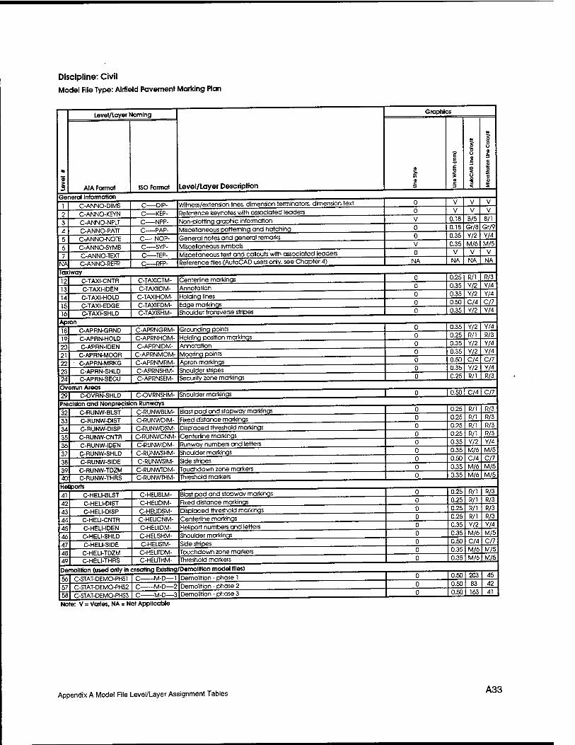
Discipline: Civil Model File Type: Airfield Pavement Marking Plan
a 1
Level/Layer Naming
Level/Layer Description
Graphics
AIA Format ISO Format o c
? E
s a c
o o o a c a < o o 2
* o o u a c =3 c o o K o D 2
1 C-ANNO-DIMS C DIP- Witness/extension lines, dimension terminators, dimension text 0 V V V
? C-ANNO-KEYN C KEP- Reference keynotes with associated leaders 0 V V V
3 C-ANNO-NPLT C NPP- Non-plottinq graphic information V 0.18 ti/b B/l
4 C-ANNO-PATT C PAP- Miscellaneous patterning and hatching 0 0.18 Gr/8 Gr/9
S C-ANNO-NOTE C NOP- General notes and general remarks 0 0.35 Y/2 Y/4
6 C-ANNO-SYMB C SYP- Miscellaneous symbols V 0.35 M/6 M/b
7 C-ANNO-TEXT C TEP- Miscellaneous text and callouts with associated leaders 0 V V V
NA C-ANNO-REFR C RFP- Reference files (AutoCAD users only, see Chapter 4) NA NA NA NA
lax
12
iway
C-TAXI-CNTR C-TAXiCTM- Centerline markings 0
0
0.25 0 35
R/l Y/2
R/3 Y/4
13 14
C-TAXI-IDEN
C-TAXI-HOLD C-TAXIHOM- Holding lines 0 0.35 Y/2 Y/4
IS C-TAXI-EDGE C-TAXIEDM- Edge markings 0 0.50 C/4 C//
16 C-TAXI-SHLD C-TAXISHM- Shoulder transverse stripes 0 0.35 Y/2 Y/4
1R C-APRN-GRND C-APRNGRM- Groundinq points 0 0.35 Y/2 Y/4
19 C-APRN-HOLD C-APRNHOM- Holding position markings 0 0.2b R/l R/3
?n C-APRN-IDEN C-APRNIDM- Annotation 0 0.35 Y/2 Y/4
?i C-APRN-MOOR C-APRNMOM- Mooring points 0 0.3b Y/2 Y/4
?? C-APRN-MRKG C-APRNMRM- Apron markings 0 0.5U C/4 C/7
93 C-APRN-SHLD C-APRNSHM- Shoulder stripes 0 0.35 Y/2 Y/4
24 C-APRN-SECU C-APRNSEM- Security zone markings 0 U.25 R/l R/3
991 C-OVRN-SHLD 1 C-OVRNSHM- IShoulder markings 1 0 I 0.50 | C/4 C//
Precision and Nonprecision Runways , . , .
3? C-RUNW-BLST C-RUNWBIM- Blast pad and stopway markings 0 U.25 k/l R/3
1? C-RUNW-DIST C-RUNWDIM- Fixed distance markings 0 0.26 R/l R/3
34 C-RUNW-DISP C-RUNWDSM- Displaced threshold markings 0 0.2b R/l R/3
35 C-RUNW-CNTR C-RUNWCNM- Centerline markings 0 0.25 R/l R/3
36 C-RUNW-IDEN C-RUNWIDM- Runway numbers and letters 0 0.35 Y/2 Y/4
17 C-RUNW-SHLD C-RUNWSHM- Shoulder markings 0 0.35 M/6 M/b
3R C-RUNW-SIDE C-RUNWSIM- Side stripes 0 0.50 C/4 C//
39 C-RUNW-TDZM C-RUNWTDM- Touchdown zone markers 0 U.35 M/6 M/5
40 C-RUNW-THRS C-RUNWTHM- Threshold markers 0 U.3b M/6 M/5
41 C-HELI-BLST C-HEUBLM- Blast pad and stopway markings 0 0.25 R/l R/3
4? C-HEL1-DIST C-HEUDIM- Fixed distance markings 0 0.2b W/l R/3
43 C-HELI-DISP C-HEUDSM- Displaced threshold markings 0 0.25 R/l R/3
44 C-HELI-CNTR C-HEUCNM- Centerline markings 0 0.25 R/l R/3
45 C-HELI-IDEN C-HEUIDM- Heliport numbers and letters 0 U.35 Y/2 Y/4
46 C-HELI-SHLD C-HEUSHM- Shoulder markings 0 U.35 M/6 M/5
47 C-HELI-SIDE C-HEUSIM- Side stripes 0 U.50 C/4 C/7
4R C-HELI-TDZM C-HELITDM- Touchdown zone markers 0 U.35 M/6 M/5
49 C-HELI-THRS C-HEUTHM- Threshold markers 0 0.3b M/6 M/5
fi6 C-STAT-DEMO-PHS1 C M-D—1 Demolition - phase 1 0 O.bu 2UJ 45
57 C-STAT-DEMO-PHS2 C M-D—2 Demolition - phase 2 0 U.50 03 42
58 C-STAT-DEMO-PHS3 C M-D—3 Demolition - phase 3 0 U.bU 163 41
Note: V = Varies, NA = Not Applicable
Appendix A Model File Level/Layer Assignment Tables A33
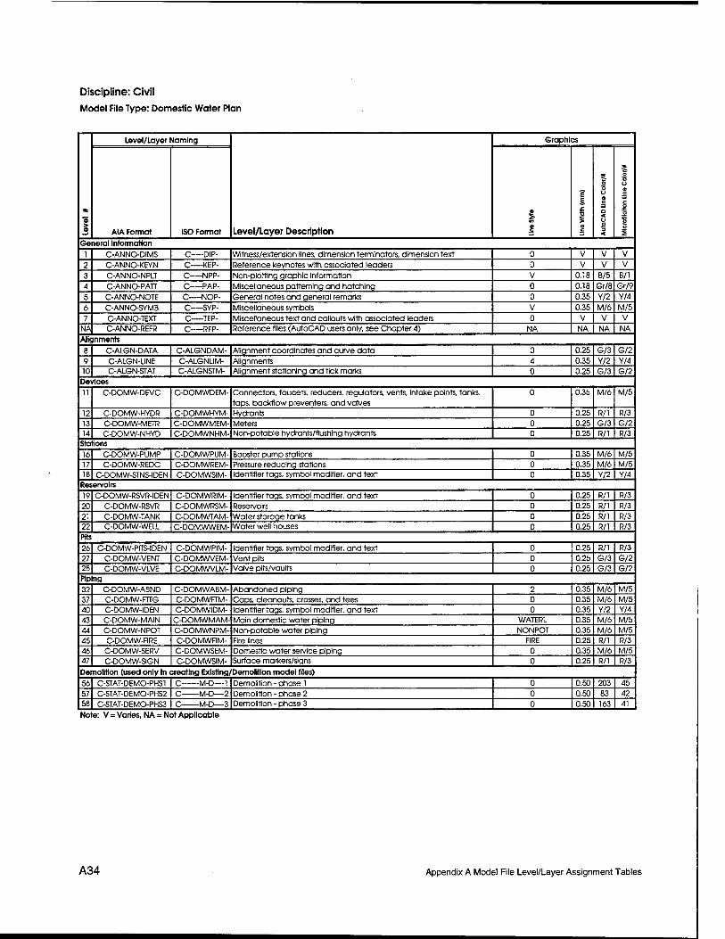
Discipline: Civil Model File Type: Domestic Water Plan
*
Level/Layer Naming
Level/Layer Description
Graphics
AIA Format ISO Format 8
e
at 5 o o a c a < o o "5 <
* o o u o c c o a S u S
General Information
1 C-ANNO-DIMS C DIP- Witness/extension lines, dimension terminators, dimension text 0 V V V
2 C-ANNO-KEYN C KEP- Reference keynotes with associated leaders 0 V V V
3 C-ANNO-NPLT C NPP- Non-plotting graphic information V 0.18 B/5 B/l
4 C-ANNO-PATT C PAP- Miscellaneous patterning and hatching 0 0.18 Gr/8 Gr/9
5 C-ANNO-NOTE C NOP- General notes and general remarks 0 0.35 Y/2 Y/4
6 C-ANNO-SYMB C SYP- Miscellaneous symbols V 0.35 M/6 M/5
7 C-ANNO-TEXT C TEP- Miscellaneous text and callouts with associated leaders 0 V V V
NA C-ANNO-REFR C RFP- Reference files (AutoCAD users only, see Chapter 4) NA NA NA NA
Alignments
8 C-ALGN-DATA C-ALGNDAM- Alignment coordinates and curve data 0 0.25 G/3 G/2
9 C-ALGN-UNE C-ALGNLIM- Alignments 4 0.35 Y/2 Y/4
10 C-ALGN-STAT C-ALGNSTM- Alignment stationing and tick marks 0 0.25 G/3 G/2 Devices
11 C-DOMW-DEVC C-DOMWDEM- Connectors, faucets, reducers, regulators, vents, intake points, tanks, taps, backflow preventers, and valves
0 0.35 M/6 M/5
12 C-DOMW-HYDR C-DOMWHYM- Hydrants 0 0.25 R/l R/3
13 C-DOMW-METR C-DOMWMEM- Meters 0 0.25 G/3 G/2 14 C-DOMW-NHYD C-DOMWNHM- Non-potable hydrants/flushing hydrants 0 0.25 R/l R/3
Stations
16 C-DOMW-PUMP C-DOMWPUM- Booster pump stations 0 0.35 M/6 M/5
17 C-DOMW-REDC C-DOMWREM- Pressure reducing stations 0 0.35 M/6 M/5 18 C-DOMW-STNS-IDEN C-DOMWSIM- Identifier tags, symbol modifier, and text 0 0.35 Y/2 Y/4
Reservoirs
19 C-DOMW-RSVR-IDEN C-DOMWRIM- Identifier tags, symbol modifier, and text 0 0.25 R/l R/3
20 C-DOMW-RSVR C-DOMWRSM- Reservoirs 0 0.25 R/l R/3
21 C-DOMW-TANK C-DOMWTAM- Water storage tanks 0 0.25 R/l R/3
22 C-DOMW-WELL C-DOMWWEM- Water well houses 0 0.25 R/l R/3
Pits
26 C-DOMW-PITS-IDEN C-DOMWPIM- Identifier tags, symbol modifier, and text 0 0.25 R/l R/3
27 C-DOMW-VENT C-DOMWVEM- Vent pits 0 0.25 G/3 G/2 28 C-DOMW-VLVE C-DOMWVLM- Valve pits/vaults 0 0.25 G/3 G/2 Piping
32 C-DOMW-ABND C-DOMWABM- Abandoned piping 2 0.35 M/6 M/5
37 C-DOMW-FTTG C-DOMWFTM- Caps, cleanouts, crosses, and tees 0 0.35 M/6 M/5
40 C-DOMW-IDEN C-DOMWIDM- Identifier tags, symbol modifier, and text 0 0.35 Y/2 Y/4
43 C-DOMW-MAIN C-DOMWMAM- Main domestic water piping WATERL 0.35 M/6 M/5
44 C-DOMW-NPOT C-DOMWNPM- Non-potable water piping NONPOT 0.35 M/6 M/5
45 C-DOMW-FIRE C-DOMWFIM- Fire lines FIRE 0.25 R/l R/3
46 C-DOMW-SERV C-DOMWSEM- Domestic water service piping 0 0.35 M/6 M/5 47 C-DOMW-SIGN C-DOMWSIM- Surface markers/signs 0 0.25 R/l R/3
Demolition (used only in creating Existing/Demolition model files)
56 C-STAT-DEMO-PHS1 C M-D—1 Demolition - phase 1 0 0.50 203 45
57 C-STAT-DEMO-PHS2 C M-D—2 Demolition - phase 2 0 0.50 83 42 58 C-STAT-DEMO-PHS3 C M-D—3 Demolition - phase 3 0 0.50 163 41
Note: V = Varies, NA = Not Applicable
A34 Appendix A Model File Level/Layer Assignment Tables
Discipline: Civil Model File Type: Sanitary Sewer Plan
Level/Layer Naming
AIA Format ISO Format Level/Layer Description General Information
C-ANNO-DIMS
C-ANNO-KEYN
C-ANNO-NPLT
C-ANNO-PATT
C-ANNO-NOTE
C-ANNO-SYMB C-ANNO-TEXT
NA C-ANNO-REFR
-DIP-
-KEP- C NPP-
-PAP-
-NOP- -SYP-
-TEP- -RFP-
Witness/extension lines, dimension terminators, dimension text
Reference keynotes with ossocioted leaders
Non-plotting graphic Information
Miscellaneous patterning and hatching
General notes and general remarks
Miscellaneous symbols Miscellaneous text and callouts with associated leaders Reference files (AutoCAD users only, see Chapter 4)
Alignments
10
C-ALGN-DATA
C-ALGN-UNE C-ALGN-STAT
C-ALGNDAM-
C-ALGNUM- C-ALGNSTM-
Alignment coordinates and curve data
Alignments Alignment stationing and tick marks
Devices
12
C-SSWR-DEVC
C-SSWR-DEVC-IDEN
C-SSWRDEM-
C-SSWRDIM-
Grease traps, grit chambers, flumes, neutralizes, oil/water separators,
ejectors, and valves Identifier tags, symbol modifier, and text
Stations
15 16 18
Reservoirs
Junction Boxes
C-SSWR-PLNT
C-SSWR-PUMP C-SSWR-STNS-DEN
C-SSWRPLM- C-SSWRPUM-
C-SSWRSIM-
Treatment plants
Booster pump stations Identifier tags, symbol modifier, and text
19 20 21
C-SSWR-RSVR-IDEN
C-SSWR-IAGN C-SSWR-TANK
C-SSWRRIM- C-SSWRLAM- C-SSWRTAM-
Identifier tags, symbol modifier, and text
Lagoons Septic tanks
22 23
C-SSWR-JBOX C-SSWR-JBOX-IDEN
C-SSWRJBM-
C-SSWRJIM-
Junction boxes and manholes Identifier tags, symbol modifier, and text
Filtration/Drainage Areas
26 27 28 29
C-SSWR-F1LT
C-SSWR-FILT-IDEN
C-SSWR-N1TF C-SSWR-LEAC
C-SSWRFIM- C-SSWRFDM-
C-SSWRNIM- C-SSWRLEM-
Filtration beds Identifier tags, symbol modifier, and text
Nitrification drain fields Leach field
Piping
32 33 37 40 43 46 47
C-SSWR-ABND
C-SSWR-FLOW C-SSWR-FTTG C-SSWR-IDEN
C-SSWR-MAIN C-SSWR-SERV C-SSWR-SIGN
C-SSWRABM- C-SSWRFLM-
C-SSWRFTM- C-SSWRIDM-
C-SSWRMAM-
C-SSWRSEM- C-SSWRSIM-
Abandoned piping Flow direction arrows
Cops and cleanouts Identifier tags, symbol modifier, and text
Sanitary sewer piping
Sanitary sewer service piping Surface markers/signs
Demolition (used only in creating Existing/Demolition model files)
56 57 58
C-STAT-DEMO-PHS1
C-STAT-DEMO-PHS2 C-STAT-DEMO-PHS3
-M-D—1
-M-D—2
-M-D—-3
Demolition - phase 1
Demolition - phase 2 Demolition - phase 3
Note: V = Varies, NA = Not Applicable
Graphics
NA
SSWAF
0.18 B/5
V
V
B/l
0.18 Gr/8 Gr/9
0.35 Y/2 0.35 M/6
Y/4
M/5 V
NA NA NA
0.25 G/3 G/2 0.35 Y/2 Y/4 0.25 G/3 G/2
0.35 M/6 M/5
0.35 M/6 M/5
0.35 M/6 M/5 0.35 M/6 M/5 0.35 Y/2
0.25 G/3 0.25 G/3 0.25 G/3
0.25 R/l 0.25 R/l
0.25 G/3 0.25 G/3 0.25 G/3 0.25 G/3
0.35 M/6 0.35 M/6 0.35
0.35
M/6 Y/2
0.35 M/6 0.25 R/l 0.25 R/l
0.50 0.50 83 0.50
Y/4
G/2 G/2
G/2
R/3
R/3
G/2 G/2 G/2
G/2
M/5 M/5 M/5 Y/4 M/5
R/3 R/3
203 45 42
163 41
Appendix A Model File Level/Layer Assignment Tables A35
Discipline: Civil Model File Type: Storm Sewer Plan
> a
Level/Layer Naming
Level/Layer Description
Graphics
AIA Format ISO Format
o & ?
6 E I 5 a c
at
O o o e c a < o o 3 <
o o o e
c o o 9 u 2
General Information
1 C-ANNO-DIMS C—DIP- Witness/extension lines, dimension terminators, dimension text 0 V V V
2 C-ANNO-KEYN C KEP- Reference keynotes with associated leaders 0 V V V
3 C-ANNO-NPLT C NPP- Non-plotting graphic information V 0.18 B/5 B/l
4 C-ANNO-PATT C PAP- Miscellaneous patterning and hatching 0 0.18 Gr/8 Gr/9
5 C-ANNO-NOTE C NOP- General notes and general remarks 0 0.35 Y/2 Y/4
6 C-ANNO-SYMB C SYP- Miscellaneous symbols V 0.35 M/6 M/5
7 C-ANNO-TEXT C TEP- Miscellaneous text and callouts with associated leaders 0 V V V
NA C-ANNO-REFR C RFP- Reference files (AutoCAD users only, see Chapter 4) NA NA NA NA
Alignments
8 C-ALGN-DATA C-ALGNDAM- Alignment coordinates and curve data 0 0.25 G/3 G/2
9 C-ALGN-LINE C-ALGNUM- Alignments 4 0.35 Y/2 Y/4
10 C-ALGN-STAT C-ALGNSTM- Alignment stationing and tick marks 0 0.25 G/3 G/2
Devices 111 C-STRM-DEVC I C-STRMDEM- |Downspouts, flumes, oil/water separators, and flap gates | 0 I 0.351 M/61 M/5
Stations
16 C-STRM-PUMP C-STRMPUM- Pump stations 0 0.35 M/6 M/5
17 C-STRM-FMON C-STRMFMM- Flow monitoring station 0 0.35 M/6 M/5
18 C-STRM-STNS-IDEN C-STRMSIM- Identifier tags, symbol modifier, and text 0 0.35 Y/2 Y/4
Reservoirs/Watersheds
19 •C-STRM-RSVR-IDEN C-STRMRIM- Identifier tags, symbol modifier, and text 0 0.25 G/3 G/2
20 C-STRM-LAGN C-STRMLAM- Lagoons, ponds, watersheds, and basins 0 0.25 G/3 G/2
21 C-STRM-AFFF C-STRMAFM- AFFF lagoon/detention pond 0 0.25 G/3 G/2
Drainage Structures
22 C-STRM-MHOL C-STRMMHM- Manholes 0 0.25 R/l R/3
26 C-STRM-DRAN-IDEN C-STRMDRM- Identifier tags, symbol modifier, and text 0 0.25 G/3 G/2
27 C-STRM-EROS C-STRMERM- Erosion control (riprap) 0 0.18 B/5 B/l
28 C-STRM-CHUT C-STRMCHM- Chutes and concrete erosion control structures 0 0.25 R/l R/3
29 C-STRM-HDWL C-STRMHDM- Headwalls and endwalls 0 0.70 W/7 W/0
30 C-STRM-INLT C-STRMINM- Inlets (curb, surface, and catch basins) 0 0.25 G/3 G/2
Piping
32 C-STRM-ABND C-STRMABM- Abandoned piping 2 0.35 M/6 M/5
33 C-STRM-FLOW C-STRMFLM- Flow direction arrows 0 0.35 M/6 M/5
37 C-SIRM-FnG C-STRMFTM- Caps and cleanouts 0 0.35 M/6 M/5
40 C-STRM-IDEN C-STRM1DM- Identifier tags, symbol modifier, and text 0 0.35 Y/2 Y/4
42 C-STRM-CULV C-STRMCLM- Culverts CULVRT 0.25 G/3 G/2
43 C-STRM-MAIN C-STRMMAM- Storm sewer piping STRAF 0.35 M/6 M/5
44 C-STRM-SUBS C-STRMSUM- Subsurface drain piping 0 0.25 G/3 G/2
45 C-STRM-ROOF C-STRMROM- Roof drain line 0 0.25 G/3 G/2
46 C-STRM-SERV C-STRMSEM- Storm sewer service piping 0 0.25 R/l R/3
47 C-STRM-SIGN C-STRMSIM- Surface markers/signs 0 0.25 R/l R/3
Demolition (used only in creating Existing/Demolition model files)
56 C-STAT-DEMO-PHS1 C M-D—1 Demolition - phase 1 0 0.50 203 45
57 C-STAT-DEMO-PHS2 C M-D—2 Demolition - phase 2 0 0.50 83 42
58 C-STAT-DEMO-PHS3 C M-D—3 Demolition - phase 3 0 0.50 163 41
Note: V = Varies, NA = Not Applicable
A36 Appendix A Model File Level/Layer Assignment Tables
Discipline: Civil
Model File Type: Industrial Waste Water Plan
level/layer Naming
AIA Format ISO Format Level/Layer Description General Information
NA
C-ANNO-DIMS C-ANNO-KEYN C-ANNO-NPLT C-ANNO-PATT C-ANNO-NOTE C-ANNO-SYMB C-ANNO-TEXT C-ANNO-REFR
-DIP- -KEP- -NPP- -PAP- -NOP- -SYP- -TEP- -RFP-
Witness/extension lines, dimension terminators, dimension text Reference keynotes with associated leaders Non-plotting graphic information Miscellaneous patterning and hatching General notes and general remarks Miscellaneous symbols Miscellaneous text and callouts with associated leaders Reference files (AutoCAD users only, see Chapter 4)
Alignments
10
C-ALGN-DATA C-ALGN-UNE C-ALGN-STAT
C-ALGNDAM- C-ALGNUM- C-ALGNSTM-
Alignment coordinates and curve data Alignments Alignment stationing and tick marks
Devices C-INDW-DEVC C-INDWDEM- Grit chambers, meters, flumes, neutralizes, oil/water separators,
ejectors, tanks, and valves Stations 15 16
C-INDW-PLNT C-INDW-UFT
C-INDW-STNS-IDEN
C-INDWPLM- C-INDWUM- C-INDWSIM-
Treatment plants Lift stations Identifier tags, symbol modifier, and text
Reservoirs 19 20
C-INDW-RSVR-IDEN C-1NDW-LAGN
C-INDWRIM- C-INDWLAM-
Identifier tags, symbol modifier, and text Lagoons
Junction Boxes 22| C-INDW-JBOX I C-INDWJBM- l-Junction boxes and manholes
Piping 32 33 37 40 43 46 47
C-INDW-ABND C-INDW-FLOW C-1NDW-FTTG C-INDW-IDEN C-INDW-MAIN C-INDW-SERV C-INDW-SIGN
C-INDWABM- C-INDWFLM- C-INDWFTM- C-INDWIDM-
C-INDWMAM- C-INDWSEM- C-INDWSIM-
Abandoned piping Flow direction arrows Caps and cleanouts Identifier tags, symbol modifier, and text Main industrial waste water piping Industrial waste water service piping Surface markers/signs
Demolition (used only in creating Existing/Demolition model flies)
56 57 58
C-STAT-DEMO-PHS1 C-STAT-DEMO-PHS2 C-STAT-DEMO-PHS3
-M-D—-1 -M-D—2 -M-D—3
Demolition - phase 1 Demolition - phase 2 Demolition - phase 3
Note: V = Varies, NA = Not Applicable
Graphics
NA
IWASTE
0.18 0.18 0.35 0.35
NA
B/5 Gr/8 Y/2 M/6
NA
B/l Gr/9 Y/4 M/5
NA
0.25 0.35 0.25
G/3 Y/2 G/3
G/2 Y/4 G/2
0.35 M/6 M/5
0.35 0.35 0.35
M/6 M/6 Y/2
M/5 M/5 Y/4
0.35 0.35
M/6 M/6
M/5 M/5
I 0.25 I R/l I R/3
0.35 0.35 0.35 0.35 0.35 0.25 0.25
M/6 M/6 M/6 Y/2 M/6 R/l R/l
M/5 M/5 M/5 Y/4 M/5 R/3 R/3
0.50 0.50 0.50
203 83 163
45 42
Appendix A Model File Level/Layer Assignment Tables A37
Discipline: Civil
Model File Type: Natural Gas Utilities Plan
■5 > a
Level/Layer Naming
Level/Layer Description
Graphics
AIA Format ISO Format a c
E £
C
O Ö O © c
0 < 0 0
1
0 0 0 0
c 0 0 0 0 5
General Information
1 C-ANNO-DIMS C—DIP- Witness/extension lines, dimension terminators, dimension text 0 V V V 2 C-ANNO-KEYN C KEP- Reference keynotes with associated leaders 0 V V V 3 C-ANNO-NPLT C NPP- Non-plotting graphic information V 0.18 B/5 B/l 4 C-ANNO-PATT C PAP- Miscellaneous patterning and hatching 0 0.18 Gr/8 Gr/9 5 C-ANNO-NOTE C NOP- General notes and general remarks 0 0.35 Y/2 Y/4 6 C-ANNO-SYMB C SYP- Miscellaneous symbols V 0.35 M/6 M/5 7 C-ANNOTEXT C TEP- Miscellaneous text and callouts with associated leaders 0 V V V
NA C-ANNO-REFR C RFP- Reference files (AutoCAD users only, see Chapter 4) NA NA NA NA Alignments
8 C-ALGN-DATA C-ALGNDAM- Alignment coordinates and curve data 0 0.25 G/3 G/2 9 C-ALGN-UNE C-ALGNLIM- Alignments 4 0.35 Y/2 Y/4 10 C-ALGN-STAT C-ALGNSTM- Alignment stationing and tick marks 0 0.25 G/3 G/2 Devices
11 C-NGAS-DEVC C-NGASDEM- Hydrant fill points, lights, vents, markers, rectifiers, reducers, regulators, sources, tanks, drip pots, taps, and valves
0 0.35 M/6 M/5
12 C-NGAS-DEVC-IDEN C-NGASDIM- Identifier tags, symbol modifier, and text 0 0.35 M/6 M/5 13 C-NGAS-METR C-NGASMEM- Meters 0 0.25 G/3 G/2
Stations
16 C-NGAS-PUMP C-NGASPUM- Compressor stations 0 0.35 M/6 M/5 17 C-NGAS-REDC C-NGASREM- Reducing stations 0 0.35 M/6 M/5 18 C-NGAS-STNS-IDEN C-NGASSIM- Identifier tags, symbol modifier, and text 0 0.35 Y/2 Y/4
Pits
26 C-NGAS-PITS-IDEN C-NGASPIM- Identifier tags, symbol modifier, and text 0 0.25 R/l R/3 27 C-NGAS-VENT C-NGASVEM- Vent pits 0 0.25 G/3 G/2 28 C-NGAS-VLVE C-NGASVLM- Valve pits/boxes 0 0.25 G/3 G/2 Piping
32 C-NGAS-ABND C-NGASABM- Abandoned piping 2 0.35 M/6 M/5 33 C-NGAS-FLOW C-NGASFLM- Flow direction arrows 0 0.25 M/6 M/5 37 C-NGAS-FTTG C-NGASFTM- Caps, crosses, and tees 0 0.35 M/6 M/5 40 C-NGAS-IDEN C-NGASIDM- Identifier tags, symbol modifier, and text 0 0.35 Y/2 Y/4 43 C-NGAS-MAIN C-NGASMAM- Main natural gas piping NTGASN 0.35 M/6 M/5 46 C-NGAS-SERV C-NGASSEM- Service piping 0 0.25 R/l R/3 47 C-NGAS-SIGN C-NGASSIM- Surface markers/signs 0 0.25 R/l R/3 Demolition (used only in creating Existing/Demolition model files)
56 C-STAT-DEMO-PHS1 C M-D—1 Demolition - phase 1 0 0.50 203 45 57 C-STAT-DEMO-PHS2 C M-D—2 Demolition - phase 2 0 0.50 83 42 58 C-STAT-DEMO-PHS3 C M-D—3 Demolition - phase 3 0 0.50 163 41 Note: V = Varies, NA = Not Applicable
A38 Appendix A Model File Level/Layer Assignment Tables
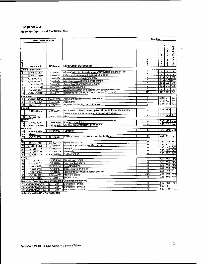
Discipline: Civil Model File Type: Liquid Fuel Utilities Plan
General Information
level/layer Naming
AIA Format ISO Format Level/Layer Description
C-ANNO-DIMS C-ANNO-KEYN
C-ANNO-NPLT
C-ANNO-PATT
C-ANNO-NOTE
C-ANNO-SYMB C-ANNO-TEXT
NA C-ANNO-REFR
-DIP-
-KEP- C NPP-
-PAP-
-NOP- -SYP-
-TEP- C RFP-
Witness/extension lines, dimension terminators, dimension text
Reference keynotes with associated leaders
Non-plotting graphic information Miscellaneous patterning and hatching
General notes and general remarks
Miscellaneous symbols Miscellaneous text and callouts with associated leaders Reference files (AutoCAD users only, see Chapter 4)
Alignments
10
C-ALGN-DATA
C-ALGN-UNE C-ALGN-STAT
C-ALGNDAM-
C-ALGNUM- C-ALGNSTM-
Alignment coordinates and curve data
Alignments Alignment stationing and tick marks
Devices
13
C-FUEL-DEVC
C-FUEL-METR
C-FUELDEM-
C-FUELMEM-
Air eliminators, filter strainers, hydrant fill points, line vents, markers,
oil/water separators, reducers, regulators, and valves
Meters
Stations
16 18
C-FUEL-PUMP C-FUEL-STNS-1DEN
C-FUELPUM- C-FUELSIM-
Booster pump stations Identifier tags, symbol modifier, and text
Reservoirs
21 I C-FUEl-TANK I C-FUELTAM- |Fuel tanks
Junction Boxes 221 C-FUEL-JBOX 1 C-FUEUBM- I Junction boxes, manholes, handholes, test boxes
Pits
25 26 27 28 29
C-FUEL-HYDR C-FUEL-PITS-IDEN
C-FUEL-VENT
C-FUEL-VLVE
C-FUEL-TRCH
C-FUELHYM- C-FUELPIM-
C-FUELVEM- C-FUELVLM-
C-FUELTRM-
Hydrant control pits Identifier tags, symbol modifier, and text
Vent pits
Valve pits Fuel line trench
Piping
32 33 36 37 40 43 46
C-FUEL-ABND
C-FUEL-FLOW
C-FUEL-DEFL C-FUEL-FTTG
C-FUEL-IDEN C-FUEL-MAIN
C-FUEL-SERV
C-FUELABM-
C-FUELFLM-
C-FUELDEM-
C-FUELFTM- C-FUEUDM-
C-FUELMAM-
C-FUELSEM-
Abandoned piping
Flow direction arrows
Defueling piping Caps, crosses, and tees Identifier tags, symbol modifier, and text
Main fuel piping Service piping
Demolition (used only in creating Existing/Demolition model files)
56 57 58
C-STAT-DEMO-PHS1
C-STAT-DEMO-PHS2
C-STAT-DEMO-PHS3
-M-D—-1
C M-D—2 -M-D—3
Demolition - phase 1
Demolition - phase 2 Demolition - phase 3
Note: V = Varies, NA = Not Applicable
Graphics
NA
UQPET
0.18
0.18 0.35 0.35
NA
B/5 Gr/8 Y/2 M/6
NA
B/l Gr/9
Y/4
M/5
NA
0.25
0.35 0.25
G/3 Y/2 G/3
G/2 Y/4 G/2
0.35
0.25
M/6
G/3
M/5
G/2
0.35
0.35
M/6 Y/2
M/5 Y/4
I 0.25 I G/3 I
[0.25 I R/1 I R/3
0.25
0.25 0.25 0.25
0.25
G/3 R/1 G/3 G/3 G/3
G/2 R/3 G/2 G/2 G/2
0.35
0.35 0.35
0.35
0.35 0.35 0.35
M/6 M/6 M/6 M/6 Y/2 M/6 M/6
M/5 M/5 M/5
M/5 Y/4
M/5
M/5
0.50 0.50
0.50
203 83 163
45 42 41
Appendix A Model File Level/Layer Assignment Tables A39
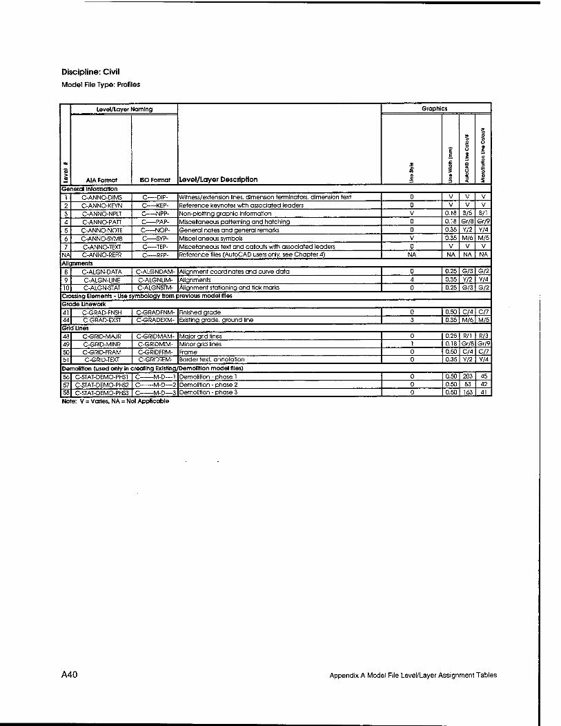
Discipline: Civil
Model File Type: Profiles
> o
—J
Level/Layer Naming
Level/Layer Description
Graphics
AIA Format ISO Format
9
£
£ ■o £ 9 c
at
O O y o c a 5 o <
* o o o e c c o
a? o 2 u £
General Information
1 C-ANNO-DIMS C DIP- Witness/extension lines, dimension terminators, dimension text 0 V V V
2 C-ANNO-KEYN C KEP- Reference keynotes with associated leaders 0 V V V
3 C-ANNO-NPLT C NPP- Non-plotting graphic information V 0.18 B/5 B/l
4 C-ANNO-PATT C PAP- Miscellaneous patterning and hatching 0 0.18 Gr/8 Gr/9
5 C-ANNO-NOTE C NOP- General notes and general remarks 0 0.35 Y/2 Y/4
6 C-ANNO-SYMB C—SYP- Miscellaneous symbols V 0.35 M/6 M/5
7 C-ANNO-TEXT C TEP- Miscellaneous text and callouts with associated leaders 0 V V V
NA C-ANNO-REFR C RFP- Reference files (AutoCAD users only, see Chapter 4) NA NA NA NA
Alignments
8 C-ALGN-DATA C-ALGNDAM- Alignment coordinates and curve data 0 0.25 G/3 G/2
9 C-ALGN-UNE _J C-ALGNUM- Alignments 4 0.35 Y/2 Y/4
10 C-ALGN-STAT C-ALGNSTM- Alignment stationing and tick marks 0 0.25 G/3 G/2 Crossing Elements • Use symbology from previous model files Grade Linework
41 C-GRAD-FNSH C-GRADFNM- Finished grade 0 0.50 C/4 C/7
44 C-GRAD-EXST C-GRADEXM- Existing grade, ground line 3 0.35 M/6 M/5
Grid Lines
48 C-GRID-MAJR C-GRIDMAM- Major grid lines 0 0.25 R/l R/3
49 C-GRID-MINR C-GR1DMIM- Minor grid lines 1 0.18 Gr/8 Gr/9
50 C-GRID-FRAM C-GRIDFRM- Frame 0 0.50 C/4 C/7
51 C-GRID-TEXT C-GRIDTEM- Border text, annotation 0 0.35 Y/2 Y/4
Demolition (used only in creating Existing/Demolition model files)
56 C-STAT-DEMO-PHS1 C M-D—1 Demolition - phase 1 0 0.50 203 45
57 C-STAT-DEMO-PHS2 C—-M-D—2 Demolition - phase 2 0 0.50 83 42
58 C-STAT-DEMO-PHS3 C M-D—3 Demolition - phase 3 0 0.50 163 41
Note: V = Varies, NA = Not Applicable
A40 Appendix A Model File Level/Layer Assignment Tables
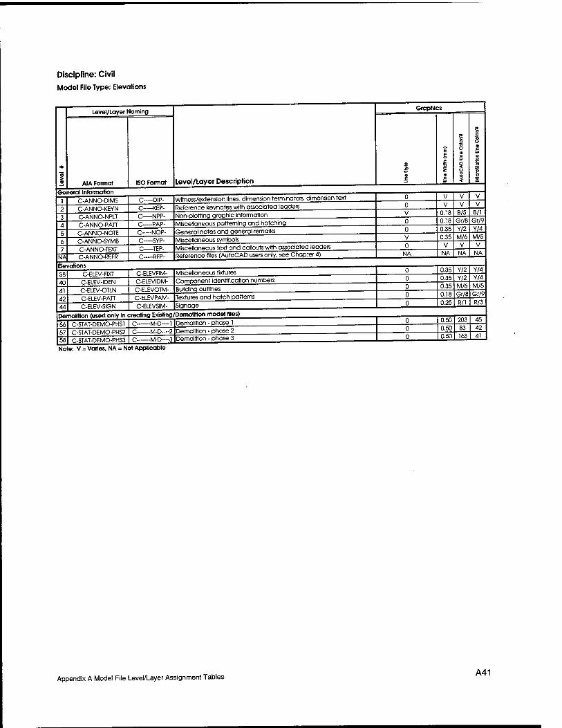
Discipline: Civil Model File Type: Elevations
General Information
Level/Layer Naming
AIA Format
NA
C-ANNO-DIMS C-ANNO-KEYN C-ANNO-NPLT C-ANNO-PATT C-ANNO-NOTE C-ANNO-SYMB C-ANNO-TEXT C-ANNO-REFR
Elevations 38 40 41 42
C-ELEV-FIXT C-ELEV-IDEN C-ELEV-OTLN C-ELEV-PATT C-ELEV-SIGN
ISO Format Level/Layer Description
-DIP- C KEP-
Witness/extension lines, dimension terminators, dimension text Reference keynotes with associated leaders ,
-NPP- Non-plotting graphic information -PAP- -NOP- -SYP- -TEP-
C—RFP-
Miscelloneous patterning and hatching General notes and general remarks Miscellaneous symbols Miscellaneous text and callouts with associated leaders Reference files (AutoCAD users only, see Chapter 4)
Graphics
0.18 0.18
B/5 Gr/8
0.35
NA
C-ELEVFIM- C-ELEVIDM- C-ELEVOTM- C-ELEVPAM- C-ELEVSIM-
Miscellaneous fixtures
0.35
NA
0.35
Y/2 M/6
NA
Y/2
Component identification numbers 0.35 Y/2
Building outlines 0.35 M/6
B/l Gr/9 Y/4 M/5
NA
Y/4 Y/4 M/5
Textures and hatch patterns 0.18
Signage 0.25 Gr/8 R/l
Gr/9 R/3
Demolition (used only in creating Existing/Demolition model tiles)
56 57 58
C-STAT-DEMO-PHS1 C-STAT-DEMO-PHS2 C-STAT-DEMO-PHS3
-M-D—-1 -M-D—2 -M-D—3
Note: V = Varies, NA = Not Applicable
Demolition - phase 1 Demolition - phase 2
0.50 0.50
203 83
Demolition - phase 3 0.50 163
45 42 41
Appendix A Model File Level/Layer Assignment Tables A41
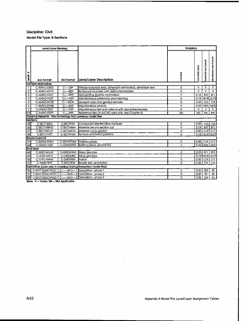
Discipline: Civil
Model File Type: X-Sections
> a
Level/Layer Naming
Level/Layer Description
Graphics
AIA Format ISO Format
V* e c =3
? E £ ■o S a c
o o u 9 c
O < Ü o 3 <
* o o o o
c o o 'S o 2
General Information
1 C-ANNO-DIMS C—DIP- Witness/extension lines, dimension terminators, dimension text 0 V V V
2 C-ANNO-KEYN C—KEP- Reference keynotes with associated leaders 0 V V V
3 C-ANNO-NPLT C NPP- Non-plotting graphic information V 0.18 B/5 B/l
4 C-ANNO-PATT C PAP- Miscellaneous patterning and hatching 0 0.18 Gr/8 Gr/9
5 C-ANNO-NOTE C NOP- General notes and general remarks 0 0.35 Y/2 Y/4
6 C-ANNO-SYMB C SYP- Miscellaneous symbols V 0.35 M/6 M/5
7 C-ANNO-TEXT C TEP- Miscellaneous text and callouts with associated leaders 0 V V V
NA C-ANNO-REFR C RFP- Reference files (AutoCAD users only, see Chapter 4) NA NA NA NA
Crossing Elements - Use symbology from previous model files
Sections
35 C-SECT-IDEN C-SECTIDM- Component identification numbers 0 0.35 Y/2 Y/4
36 C-SECT-MBND C-SECTMBM- Material beyond section cut 0 0.18 B/5 B/l
37 C-SECT-MCUT C-SECTMCM- Material cut by section 0 0.50 C/4 C/7 38 C-SECT-PATT C-SECTPAM- Textures and hatch patterns 0 0.18 Gr/8 Gr/9
Grade Linework
41 C-GRAD-FNSH C-GRADFNM- Finished grade 0 0.50 C/4 C/7 44 C-GRAD-EXST C-GRADEXM- Existing grade, ground line 3 0.35 M/6 M/5
Grid Lines
48 C-GRID-MAJR C-GRIDMAM- Major grid lines 0 0.25 R/l R/3
49 C-GRID-MINR C-GRIDMIM- Minor grid lines 1 0.18 Gr/8 Gr/9
50 C-GRID-FRAM C-GRIDFRM- Frame 0 0.50 C/4 C/7 51 C-GRID-TEXT C-GRIDTEM- Border text, annotation 0 0.35 Y/2 Y/4
Demolition (used only in creating Existing/Demolition model files)
56 C-STAT-DEMO-PHS1 C M-D—1 Demolition - phase 1 0 0.50 203 45
57 C-STAT-DEMO-PHS2 C—M-D—2 Demolition - phase 2 0 0.50 83 42 58 C-STAT-DEMO-PHS3 C M-D—3 Demolition - phase 3 0 0.50 163 41
Note: V = Varies, NA = Not Applicable
A42 Appendix A Model File Level/Layer Assignment Tables

Discipline: Civil Model File Type: Details
> a
Level/layer Naming
Level/Layer Description
Graphics
AIA Format ISO Format O c
E E £
o c =3
o ■5 u a c =i a < o o 3 <
o o u « c o I u 2
1 C-ANNO-DIMS C—DIP- Witness/extension lines, dimension terminators, dimension text 0 V V V
f C-ANNO-KEYN C KEP- Reference keynotes with associated leaders 0 V V V
1 C-ANNO-NPLT C NPP- Non-plotting graphic information V U.IÖ ti/b b/l
d C-ANNO-PATT C PAP- Miscellaneous patterning 0 u.ia Gr/8 Gr/9
"i C-ANNO-NOTE C NOP- General notes and general remarks 0 U.3b Y/2 Y/4
6 C-ANNO-SYMB C SYP- Reference bubbles, matchlines and breaklines V u.3b M/6 M/5
7 C-ANNO-TEXT C TEP- Detail title text, text and associated leaders, notes V V V V
11 C-DETL-GRPH C-DETLGRM- Graphics, qridlines, non-text items V V V V
T? C-DETL-METR C-DETLMEM- Metric-specific dimensions and notes 0 U.2b G/3 G/2
n C-DETL-INPD C-DETUNM- Inch-pound-specific dimensions and notes 0 U.2b W\ R/3
.Vi C-STAT-DEMO-PHS1 C M-D—-1 Demolition - phase 1 0 U.bU 203 4t>
57 58
C-STAT-DEMO-PHS2 C-STAT-DEMO-PHS3
C M-D—2
C M-D—3
Demolition - phase 2 Demolition - phase 3
0 0
0.50 0.50
83 163
42 41
Note: V = Varies, NA = Not Applicable
Appendix A Model File Level/Layer Assignment Tables A43

Discipline: Landscape Model File Type: Landscape Plan
> a
Level/Layer Naming
Level/Layer Description
Graphics
AIA Format ISO Format
a
a
£ c V % 9 2
5 o o o c a <
3
o "5 o a c c o £ g o
General Information
1 L-ANNO-DIMS L DIP- Witness/extension lines, dimension terminators, dimension text 0 V V V 2 L-ANNO-KEYN L KEP- Reference keynotes with associated leaders 0 V V V 3 L-ANNO-NPLT L NPP- Non-plotting graphic information V 0.18 B/5 B/l 4 L-ANNO-PATT L PAP- Miscellaneous patterning and hatching 0 0.18 Gr/8 Gr/9 5 L-ANNO-NOTE L NOP- General notes and general remarks 0 0.35 Y/2 Y/4 6 l-ANNO-SYMB L SYP- Miscellaneous symbols V 0.35 M/6 M/5 7 L-ANNO-TEXT L TEP- Miscellaneous text and callouts with associated leaders 0 V V V
NA L-ANNO-REFR L RFP- Reference files (AutoCAD users only, see Chapter 4) NA NA NA NA Site Improvements
11 L-SITE-BRDG L-SITEBRM- Bridges 0 0.35 22 22 12 L-SITE-DECK L-SITEDEM- Decks 0 0.35 232 107 13 L-SITE-FENC L-SITEFEM- Fencing 0 0.35 Y/2 Y/4 14 L-SITE-FURN L-SITEFUM- Furnishings 0 0.50 C/4 C/7 15 L-SITE-IDEN L-SITEIDM- . Annotation 0 0.35 M/6 M/5 16 L-SITE-PLAY L-SITEPLM- Play structures 0 0.35 Y/2 Y/4 17 L-SITE-POOL L-SiTEPOM- Pools and spas 0 0.35 162 33 18 L-SITE-ROCK L-SITEROM- Boulders and cobble 0 0.25 R/l R/3 19 L-SITE-SPRT L-SITESPM- Sports fields 0 0.35 Y/2 Y/4 20 L-SITE-WALK L-SITEWAM- Walks and steps 0 V V V 21 L-SITE-RTWL l-SITERTM- Retaining walls 0 0.50 C/4 C/7 Landscape Plants 23 L-PLNT-BEDS L-PLNTBEM- Planting beds 0 0.35 M/6 M/5 24 L-PLNT-TURF L-PLNTTUM- Lawn areas (turfing limits) 0 0.50 23 46 25 L-PLNT-MLCH L-PLNTMLM- Mulches - organic and inorganic 0 0.25 G/3 G/2 26 L-PLNT-GRND L-PLNTGRM- Groundcover and vines 0 0.35 82 18 27 L-PLNT-IDEN L-PLNTIDM- Annotation 0 0.35 M/6 M/5 28 L-PLNT-PLTS L-PLNTPLM- Planting plants (e.g.. ornamental annuals and perennials) 0 0.50 83 42 29 L-PLNT-BUSH-L1NE L-PLNTBLM- Bush and shrub line 0 0.50 83 42 30 L-PLNT-BUSH L-PLNTBUM- Bushes and shrubs (e.g., evergreen, deciduous) 0 0.50 83 42 31 L-PLNT-TREE-LINE L-PLNTTLM- Tree line TREEL 0.50 83 42 32 L-PLNT-TREE L-PLNTTRM- Trees (e.g.. evergreen, deciduous, etc.) 0 0.50 83 42 33 L-PLNT-SPRG L-PLNTSPM- Sprigs 0 0.25 G/3 G/2 34 L-PLNT-CTNR L-PLNTCTM- Containers or planters 0 0.25 R/l R/3 35 L-PLNT-SHAD L-PLNTSHM- Shadow areas 0 0.18 B/5 B/l Demolition (used only in creating Existing/Demolition model files)
56 L-STAT-DEMO-PHS1 L M-D—1 Demolition - phase 1 0 0.50 203 45 57 L-STAT-DEMO-PHS2 L M-D—2 Demolition - phase 2 0 0.50 83 42 58 L-STAT-DEMO-PHS3 I M-D—3 Demolition - phase 3 0 0.50 163 41 Note: V = Varies, NA = Not Applicable
A44 Appendix A Model File Level/Layer Assignment Tables
Discipline: Landscape Model File Type: Irrigation Plan
General Information
Level/Layer Naming
AIA Format ISO Format Level/Layer Description
NA
L-ANNO-DMS L-ANNO-KEYN L-ANNO-NPLT L-ANNO-PATT L-ANNO-NOTE L-ANNO-SYMB L-AN NO-TEXT L-ANNO-REFR
Irrigation System
L DIP- L KEP- Reference keynotes with associated leaders
-NPP- L—PAP- L—NOP-
-SYP- -TEP-
L RFP-
Witness/extension lines, dimension terminators, dimension text
Non-plottina graphic information Miscellaneous patterning and hatching General notes and general remarks Miscellaneous symbols Miscellaneous text and callouts with associated leaders Reference files (AutoCAD users only, see Chapter 4)
25 26 27 28 31 34
L-IRRG-COVR L-IRRG-EQPM L-IRRG-IDEN L-IRRG-PIPE L-IRRG-SPKL
L-IRRG-HEAD
L-IRRGCOM- L-IRRGEQM- Equipment (e.g., controllers, valves, RPBPs, etc) L-IRRGIDM- L-IRRGPIM- L-IRRGSPM- L-IRRGHEM-
Irrigation coverage, spray distribution patterns
Annotation
Graphics
NA
Piping Sprinklers
Demolition (used only in creating Existing/Demolition model files)
Irrigation heads, bubblers, and drip irrigation emitters
LAWNSP
56 57 58
L-STAT-DEMO-PHS1 L-STAT-DEMO-PHS2 L-STAT-DEMO-PHS3
L M-D—-1 Demolition - phase 1 -M-D—2 -M-D—3
Note: V = Varies, NA = Not Applicable
Demolition - phase 2 Demolition - phase 3
0.18 B/5 B/l 0.18 Gr/8 Gr/9 0.35 Y/2 Y/4 0.35 M/6 M/5
NA NA NA
0.18 B/5 B/l 0.35 M/6 M/5 0.35 Y/2 0.35 M/6
Y/4 M/5
0.35 M/6 M/5 0.25 R/l R/3
0.50 203 45 0.50 83 42 0.50 163 41
Appendix A Model File Level/Layer Assignment Tables A45
Discipline: Landscape Model File Type: Details
> a
Level/Layer Naming
Level/Layer Description
Graphics
AIA Format ISO Format
£■ a c
E £ B
s o c
a*
O O O 9 C
a < o o 5
* o o o e c
tz o
o u 2
General Information
1 L-ANNO-DIMS L DIP- Witness/extension lines, dimension terminators, dimension text 0 V V V 2 L-ANNO-KEYN L KEP- Reference keynotes with associated leaders 0 V V V 3 L-ANNO-NPLT L NPP- Non-plotting graphic information V 0.18 B/5 B/l 4 L-ANNO-PATT L PAP- Miscellaneous patterning 0 0.18 Gr/8 Gr/9 5 L-ANNO-NOTE L NOP- General notes and general remarks 0 0.35 Y/2 Y/4 6 L-ANNO-SYMB L SYP- Reference bubbles, matchlines and breaklines V 0.35 M/6 M/5 7 L-ANNO-TEXT L TEP- Detail title text, text and associated leaders, notes V V V V
Detail Information
11 L-DETL-GRPH L-DETLGRM- Graphics, gridlines, non-text items V V V V 12 L-DETL-METR L-DETLMEM- Metric-specific dimensions and notes 0 0.25 S/3 G/2 13 L-DETL-INPD L-DETUNM- Inch-pound-specific dimensions and notes 0 0.25 R/l R/3
Demolition
56 L-STAT-DEMO-PHS1 L M-D—1 Demolition - phase 1 0 0.50 203 45 57 L-STAT-DEMO-PHS2 L M-D—2 Demolition - phase 2 0 0.50 83 42 58 L-STAT-DEMO-PHS3 L M-D—3 Demolition - phase 3 0 0.50 163 41 Note: V = Varies, NA = Not Applicable
A46 Appendix A Model File Level/Layer Assignment Tables
Discipline: Structural
Model File Type: Foundation Plan
General Information
Level/layer Naming
AIA Format ISO Format Level/Layer Description
NA
S-ANNO-DIMS S-ANNO-KEYN S-ANNO-NPLT
S-ANNO-PATT
S-ANNO-NOTE
S-ANNO-SYMB S-ANNO-TEXT S-ANNO-REFR
S D1P- Witness/extension lines, dimension terminators, dimension text
S—KEP-
S—NPP- S—PAP-
Reference keynotes with associoted leaders
Non-plotting graphic information
S—NOP-
S—SYP-
-TEP- S—RFP-
Miscellaneous patterning and hatching
General notes and general remarks
Miscellaneous symbols Miscellaneous text and callouts with associated leaders Reference files (AutoCAD users only, see Chapter 4)
Foundation
16 17 18 19 20
S-FNDN-CNTR
S-FNDN-FTNG S-FNDN-GRBM
S-FNDN-PEDS S-FNDN-PILE
S-FNDN-RBAR
S-FNDNCNM-
S-FNDNFTM- S-FNDNGRM-
S-FNDNPEM-
S-FNDNPIM- S-FNDNRBM-
Beam centerlines
Footings
Grade beams Column pedestals Piles (steel sheet, concrete, wood), piers, caisson piers, drilled piers
Foundation reinforcing
Slabs
21 26 28
S-SLAB-OPEN
S-SLAB-EDGE S-SLAB-RBAR
S-SIABOPM-
S-SLABEDM- S-SLABRBM-
Openings and penetrations
Edge of slab Slab reinforcing
Grating
30
Joints
Miscellaneous Supports
Stairs and Elevators
Walls
31 S-GRAT-ELEV S-GRAT-FLOR
S-GRATELM- S-GRATFLM-
Elevated grating (catwalks) Floor grating
33 34
S-JOIN-CNST S-JOIN-CTRL
S-JOINCNM- S-JOINCTM-
Construction joints Control/expansion joints
35 36
S-SPPT-MISC S-SPPT-SHPS
S-SPPTMIM- S-SPPTSHM-
Miscellaneous fasteners, anchor bolts, supports Miscellaneous shapes, plates
38 39 40
S-STRS-FRAM
S-STRS-LADD S-STRS-RBAR
S-STRSFRM- S-STRSLAM- S-STRSRBM-
Stair/elevator framing Ladders, ladder handrails, safety guard, grab bars Stair reinforcing
43
45 46 47
S-WALL-CONC S-WALL-LOAD S-WALL-NONL S-WALL-PCST
S-WALL-STUD S-WALL-RBAR
S-WALLCOM- Concrete walls
S-WALLLOM- S-WALLNOM-
S-WALLPCM-
S-WALLSTM- S-WALLRBM-
Lood bearing CMU walls Non-load bearing CMU walls
Precast walls
Stud walls Wall reinforcing
Pads 491 S-PADS-EQPM | S-PADSEQM- | Equipment pads
Demolition (used only in creating Existing/Demolition model tiles)
56 57 58
S-STAT-DEMO-PHS1
S-STAT-DEMO-PHS2
S-STAT-DEMO-PHS3
S M-D—1 Demolition - phase 1
-M-D---2
-M-D—-3
Note: V = Varies, NA = Not Applicable
Demolition - phase 2 Demolition - phase 3
Graphics
NA
0,2 0,2 0,2 0,2 0,2
0,2 0.2 0,2
0.2 0,2
0,2 0,2
0.2 0.2 0,2
0,2 0,2 0,2 0,2 0.2 0,2
0.2
0.18 B/5 0.18 0.35
Gr/8 Y/2
B/l Gr/9 Y/4
0.35 M/6
NA
M/5 V
NA
0.18 B/5 B/l 0.50
0.50
C/4
C/4 0.50 C/4 0.35 0.70
Y/2 W/7
C/7 C/7 C/7 Y/4 W/0
0.25
0.35 R/l Y/2
R/3 Y/4
0.70 W/7 W/0
0.25 G/3 0.25 G/3
G/2 G/2
0.25 G/3 0.25 R/l
0.25 G/3 0.25 G/3
G/2 R/3
G/2
G/2
0.35 M/6 M/5 0.25 G/3 G/2 0.70 W/7 W/0
0.35 Y/2 0.35 Y/2 0.35 M/6
Y/4 Y/4 M/5
0.35 Y/2 0.35
0.70
Y/2 W/7
Y/4 Y/4 W/0
0.50
0.50
203
83
0.50 163
45 42 41
Appendix A Model File Level/Layer Assignment Tables A47
Discipline: Structural
Model File Type: Framing Plan
> a
Level/Layer Naming
Level/Layer Description
Graphics
AIA Format ISO Format
o £■ o c
E £ £
S a c
« o o o 0 C
a < u o 3 <
O O u C
c o
2 u 2
General Information
1 S-ANNO-D1MS S DIP- Witness/extension lines, dimension terminators, dimension text, welding
symbols
0 V V V
2 S-ANNO-KEYN S KEP- Reference keynotes with associated leaders 0 V V V
3 S-ANNO-NPLT S NPP- Non-plotting graphic information V 0.18 B/5 B/l
4 S-ANNO-PATT S PAP- Miscellaneous patterning and hatching 0 0.18 Gr/8 Gr/9
5 S-ANNO-NOTE S NOP- General notes and general remarks 0 0.35 Y/2 Y/4
6 S-ANNO-SYMB S SYP- Miscellaneous symbols V 0.35 M/6 M/5
7 S-ANNO-TEXT S—TEP- Miscellaneous text and callouts with associated leaders 0 V V V
NA S-ANNO-REFR S—RFP- Reference files (AutoCAD users only, see Chapter 4) NA NA NA NA
Beams
n S-BEAM-CNTR S-BEAMCNM- Beam centerlines 7 0.18 B/5 B/l
12 S-BEAM-PRIM S-BEAMPRM- Primary beams, girders 0,2 0.50 C/4 C/7
13 S-BEAM-SECD S-BEAMSCM- Secondary beams, girders 0,2 0.35 M/6 M/5 Bracing
16 S-BRAC-LATL S-BRACLAM- Lateral bracing 0,2 0.35 Y/2 Y/4
17 S-BRAC-SHEA S-BRACSHM- Shear walls 0,2 0.35 Y/2 Y/4
18 S-BRAC-VERT S-BRACVEM- Vertical bracing 0,2 0.35 Y/2 Y/4
Deck
19 S-DECK-FLOR S-DECKFLM- Floor deck 0,2 0.25 G/3 G/2
20 S-DECK-RBAR S-DECKRBM- Deck/slab reinforcing 0,2 0.70 W/7 W/0
21 S-DECK-OPEN S-DECKOPM- Openings and penetrations 0,2 0.25 R/l R/3
22 S-DECK-ROOF S-DECKROM- Roof deck 0 0.25 G/3 G/2 Open Web Joists
23 S-JOIS-PRIM S-JOISPRM- Primary joists 0.2 0.50 C/4 C/7
24 S-JOIS-SECD S-JOISSCM- Secondary joists 0,2 0.35 M/6 M/5
25 S-JOIS-BRDG S-JOISBRM- Bridging 2 0.25 R/l R/3
Miscellaneous Metal 29| S-METL-MISC | S-METLMIM- (Miscellaneous metal | 0.2 10.351M/61M/5
Joints
33 S-JOIN-CNST S-JOINCNM- Construction joints 0 0.25 G/3 G/2
34 S-JOIN-CTRL S-JOINCTM- Control/expansion joints 0 0.25 R/l R/3
Miscellaneous Supports
35 S-SPPT-MISC S-SPPTMIM- Miscellaneous fasteners, anchor bolts, supports 0,2 0.25 G/3 G/2
36 S-SPPT-SHPS S-SPPTSHM- Miscellaneous shapes, plates 0,2 0.25 G/3 G/2 Stairs and Elevators
38 S-STRS-FRAM S-STRSFRM- Stair/elevator framing 0,2 0.35 M/6 M/5
39 S-STRS-LADD S-STRSLAM- Ladders, ladder handrails, safety guard, grab bars 0,2 0.25 G/3 G/2
40 S-STRS-RBAR S-STRSRBM- Stair reinforcing 0,2 0.70 W/7 W/0
Trusses
41 S-TRUS-PRIM S-TRUSPRM- Primary trusses 0,2 0.50 C/4 C/7
42 S-TRUS-SECD S-TRUSSCM- Secondary trusses 0,2 0.35 M/6 M/5
Walls
43 S-WALL-CONC S-WALLCOM- Concrete walls 0,2 0.35 Y/2 Y/4
44 S-WALL-LOAD S-WALLLOM- Load bearing CMU walls 0,2 0.35 Y/2 Y/4
45 S-WALL-NONL S-WALLNOM- Non-load bearing CMU walls 0,2 0.35 M/6 M/5
46 S-WALL-PCST S-WALLPCM- Precast walls 0,2 0.35 Y/2 Y/4
47 S-WALL-STUD S-WALLSTM- Stud walls 0,2 0.35 Y/2 Y/4
48 S-WALL-RBAR S-WALLRBM- Wall reinforcing 0,2 0.70 W/7 W/0
Demolition (used only in creating Existing/Demolition model files)
56 S-STAT-DEMO-PHS1 S M-D—1 Demolition - phase 1 0 0.50 203 45
57 S-STAT-DEMO-PHS2 S—M-D—2 Demolition - phase 2 0 0.50 83 42
58 S-STAT-DEMO-PHS3 S M-D—3 Demolition - phase 3 0 0.50 163 41
Note: V = Varies, NA = Not Applicable
A48 Appendix A Model File Level/Layer Assignment Tables
Discipline: Structural Model File Type: Column Plan
General Information
level/layer Naming
AIA Format ISO Format Level/Layer Description
NA
S-ANNO-DIMS S-ANNO-KEYN S-ANNO-NPLT S-ANNO-PATT S-ANNO-NOTE S-ANNO-SYMB S-ANNO-TEXT S-ANNO-REFR
Grid Lines
S DIP- Witness/extension lines, dimension terminators, dimension text
S—KEP- S—NPP-
Reference keynotes with associated leaders Non-plotting graphic information
S—PAP- S—NOP- S—SYP- S—TEP- S—RFP-
Miscellaneous patterning and hatching General notes and general remarks Miscellaneous symbols Miscellaneous text and callouts with associated leaders Reference files (AutoCAD users only, see Chapter 4)
10
12 13 14
S-GRID-IDEN S-GRID-HORZ S-GR1D-VERT
S-GRID-MSC1 S-GRID-MSC2 S-GRID-MSC3 S-GRID-MSC4
S-GRIDIDM- Column I.D. tags S-GRIDHOM- S-GRIDVEM-
Primary grid lines (horizontal)
S-GRIDM1M- Primary grid lines (vertical)
S-GRIDM2M- S-GRIDM3M- S-GR1DM4M-
Miscellaneous grid lines (Type 1) Miscellaneous grid lines (Type 2) Miscellaneous grid lines (Type 3) Miscellaneous grid lines (Type 4)
Columns 16 17 18 19 20 21 22
S-COLS-CNTR S-COIS-PRIM S-COLS-SCND S-COLS-MSC1 S-COLS-MSC2 S-COLS-MSC3 S-COLS-MSC4
S-COLSCNM- S-COLSPRM-
Column centerlines/working lines Primary columns
S-COLSSCM- Secondary columns S-COLSM1M- S-COLSM2M- S-COLSM3M- S-COLSM4M-
Miscelloneous columns (Type 1) Miscellaneous columns (Type 2) Miscellaneous columns (Type 3) Miscellaneous columns (Type 4)
Demolition (used only in creating Existing/Demolition model files)
56 57 58
S-STAT-DEMO-PHS1 S-STAT-DEMO-PHS2 S-STAT-DEMO-PHS3
-M-D—1 -M-D—2 -M-D—3
Demolition - phase 1 Demolition - phase 2 Demolition - phase 3
Note: V = Varies, NA = Not Applicable
Graphics
NA
0.18 0.18
B/5 Gr/8
V B/l
Gr/9 0.35 Y/2 Y/4 0.35 M/6 M/5
NA NA NA
0.25 0.18
R/l B/5
0.18 0.18
B/5 Gr/8
R/3 B/l B/l
Gr/9 0.18 Gr/8 Gr/9 0.18 Gr/8 Gr/9 0.18 Gr/8
0.18 10
Gr/9
10 0,35 0.35
M/6 Y/2
M/5 Y/4
0.35 22 22 0.35 0.35
22 22
0.35 22
22 22 22
0.50 203 0.50 83
45 42
0.50 163 41
Appendix A Model File Level/Layer Assignment Tables A49
Discipline: Structural
Model File Type: Non-Building Structures
* 75
I
Level/Layer Naming
Level/Layer Description
Graphics
AIA Format ISO Format o c
£ ■D 5 o c
a«
o o o a c a < ü o 3 <
* o o u 9
c o o S o S
General Information
1 S-AN NO-DIMS S—D1P- Witness/extension lines, dimension terminators, dimension text, welding
symbols 0 V V V
2 S-ANNO-KEYN S KEP- Reference keynotes with associated leaders 0 V V V 3 S-ANNO-NPLT S NPP- Non-plotting graphic information V 0.18 B/5 B/l 4 S-ANNO-PATT S—PAP- Miscellaneous patterning and hatching 0 0.18 Gr/8 Gr/9 5 S-ANNO-NOTE S NOP- General notes and general remarks 0 0.35 Y/2 Y/4 6 S-ANNO-SYMB S SYP- Miscellaneous symbols V 0.35 M/6 M/5 7 S-ANNO-TEXT S—TEP- Miscellaneous text and callouts with associated leaders 0 V V V
NA S-ANNO-REFR S—RFP- Reference files (AutoCAD users only, see Chapter 4) NA NA NA NA Features
9 S-FEAT-GENL S-FEATGEM- General features (miscellaneous items) 0,2 0.35 M/6 M/5 10 S-FEAT-CMUW S-FEATCMM- CMU outline (no patterning) 0.2 0.35 Y/2 Y/4 11 S-FEAT-CNTR S-FEATCNM- Feature centerlines 7 0.18 B/5 B/l 15 S-FEAT-CONC S-FEATCOM- Concrete outline (no patterning) 0,2 0.35 M/6 M/5 20 S-FEAT-WOOD S-FEATWOM- Wood outline (no patterning) 0,2 0.35 Y/2 Y/4 Foundation 19| S-FNDN-PILE |S-FNDNPIM- |Piles (steel sheet, concrete, wood), piers, caisson piers, drilled piers | 0,2 | 0.35 | Y/2 | Y/4
Openings 211 S-OPEN-MISC IS-OPENM1M- |Openings and penetrations | 0,2 | 0.251 R/l I R/3
Piping
25 S-PIPE-MISC S-P1PEMIM- Miscellaneous piping/culverts 0,2 0.35 Y/2 Y/4 26 S-PIPE-GATE S-PiPEGAM- Gates (flap gates, sluice gates, other) 0,2 0.25 G/3 G/2 27 S-PIPE-TRSH S-PIPETRM- Trash racks 0,2 0.25 G/3 G/2 Grating
30 S-GRAT-ELEV S-GRATELM- Elevated grating (catwalks) 0,2 0.25 G/3 G/2 31 S-GRAT-FLOR S-GRATFLM- Floor/surface grating, manhole covers/frames 0,2 0.25 G/3 G/2 32 S-GRAT-SUBS S-GRATSUM- Subsurface grating 0,2 0.25 G/3 G/2 Joints
33 S-JOIN-CNST S-JOINCNM- Construction joints 0 0.25 G/3 G/2 34 S-JOIN-CTRL S-JOINCTM- Control/expansion joints, joint materials (e.g.. felt), vapor barrier,
waterstops, other 0 0.25 R/l R/3
Miscellaneous Supports
35 S-SPPT-MISC S-SPPTMIM- Miscellaneous fasteners, anchor bolts, supports 0.2 0.25 G/3 G/2 36 S-SPPT-SHPS S-SPPTSHM- Miscellaneous shapes, plates 0,2 0.25 G/3 G/2 Stairs and Elevators
38 S-STRS-FRAM S-STRSFRM- Stair/elevator framing 0.2 0.35 M/6 M/5 39 S-STRS-LADD S-STRSLAM- Ladders, ladder handrails, safety guard, grab bars 0.2 0.25 G/3 G/2 Reinforcing
401 S-REIN-RBAR |S-REINRBM- |Rebar. welded wire mesh | 0.2 | 0.701W/71W/0 Safety Barriers
42 S-SAFE-HRAL S-SAFEHRM- Handrails 0 0.25 G/3 G/2 43 S-SAFE-FENC S-SAFEFEM- Fencing 0 0.25 G/3 G/2 Grade lines
45 S-GRDL-FNGR S-GRDLFNM- Finished grade 0 0.35 Y/2 Y/4 46 S-GRDL-EXGL S-GRDLEXM- Existing ground 3 0.25 G/3 G/2 47 S-GRDL-WATR S-GRDLWAM- Water surface 0 0.25 G/3 G/2 Demolition (used only in creating Existing/Demolition model files)
56 S-STAT-DEMO-PHS1 S M-D—1 Demolition - phase 1 0 0.50 203 45 57 S-STAT-DEMO-PHS2 S——M-D—2 Demolition - phase 2 0 0.50 83 42 58 S-STAT-DEMO-PHS3 S——M-D—3 Demolition - phase 3 0 0.50 163 41 Note: V = Varies, NA = Not Applicable
A50 Appendix A Model File Level/Layer Assignment Tables
Discipline: Structural Model File Type: Elevations
General Information
Level/Layer Naming
AIA Format ISO Format
Graphics
Level/Layer Description
NA
S-ANNO-DIMS S-ANNO-KEYN
S-ANNO-NPLT
S-ANNO-PATT
S-ANNO-NOTE
S-ANNO-SYMB
S-ANNO-TEXT S-ANNO-REFR
S DIP-
S KEP-
Witness/extension lines, dimension terminators, dimension text
Reference keynotes with associated leaders
-NPP- Non-plotting graphic information
S—PAP-
S—NOP- --SYP-
S—TEP-
S—RFP-
Miscellaneous patterning and hatching
General notes and general remarks
Miscellaneous symbols Miscellaneous text and callouts with associated leaders Reference files (AutoCAD users only, see Chapter 4)
Beams
12 13
S-BEAM-CNTO S-BEAMCNM-
S-BEAM-PRIM S-BEAM-SECD
S-BEAMPRM- S-BEAMSCM-
Beam centerlines Primary beams/girders outlines Secondary beams/girders outlines
Joints
33 34
S-JOIN-CNST S-JOINCNM-
S-JOIN-CTRL
Miscellaneous Supports
S-JOiNCTM-
Construction joints Control/expansion joints
35 36
S-SPPT-MISC S-SPPTMIM-
S-SPPT-SHPS S-SPPTSHM-
Mlscellaneous fasteners, anchor bolts, supports Miscellaneous shapes, plates
Walls
43 45
Demolition (used only in creating Existing/Demolition model flies)
46 49
S-WALL-OTLN S-WALLOTM- S-WALL-VBAR S-WALLVBM- S-WAU.-HBAR S-WALL-OPEN
Wall outline
S-WAUHBM- S-WALLOPM-
Vertical/primary reinforcement Horizontal/secondary reinforcement Openings and penetrations
56 57 58
S-STAT-DEMO-PHS1 S-STAT-DEMO-PHS2 S-STAT-DEMO-PHS3
-M-D—1 -M-D—2 -M-D—3
Demolition - phase 1 Demolition - phase 2 Demolition - phase 3
Note: V = Varies, NA = Not Applicable
NA
0.2 0,2
0,2 0,2
0,2 0,2 0,2 0,2
E g
0.35 Y/2 Y/4 0.18 B/5 B/l 0.18 Gr/8
0.35 Y/2 0.35 M/6
Gr/9 Y/4
M/5
0.35 NA
Y/2 Y/4
NA
0.18 B/5 B/l 0.50 C/4 C/7 0.35 M/6 M/5
0.25 0.25
G/3
R/l
0.25 G/3
G/2 R/3
"G72 0.25 G/3 G/2
0.35 Y/2 0.50 C/4
Y/4 C/7
0.50 0.25
C/4
R/l
C/7
R/3
0.50 203 0.50 83 0.50
45
163 42 41
Appendix A Model File Level/Layer Assignment Tables A51
Discipline: Structural
Model File Type: Sections
> s
Level/Layer Naming
Level/Layer Description
Graphics
AIA Format ISO Format a c
E E £ ä a c
o o u 9
a < o o <
o o o « c c o
s u
General Information
1 S-ANNO-DIMS S DIP- Witness/extension lines, dimension terminators, dimension text, welding symbols
0 V V V
2 S-ANNO-KEYN S KEP- Reference keynotes with associated leaders 0 V V V 3 S-ANNO-NPLT S NPP- Non-plotting graphic information V 0.18 B/5 B/l 4 S-ANNO-PATT S PAP- Miscellaneous patterning and hatching 0 0.18 Gr/8 Gr/9 5 S-ANNO-NOTE S NOP- General notes and general remarks 0 0.35 Y/2 Y/4 6 S-ANNO-SYMB S SYP- Reference bubbles, matchlines and breaklines V 0.35 M/6 M/5 7 S-ANNO-TEXT S TEP- Miscellaneous text and callouts with associated leaders 0 V V V
NA S-ANNO-REFR S RFP- Reference files (AutoCAD users only, see Chapter 4) NA NA NA NA Section Information
9 S-SECT-GENF S-SECTGEM- General features (miscellaneous items) 0,2 0.35 M/6 M/5 10 S-SECT-CMUW S-SECTCMM- CMU outline (no patterning) 0,2 0.35 Y/2 Y/4 11 S-SECT-CNTR S-SECTCNM- Centerlines 7 0.18 B/5 B/l 12 S-SECT-PRIM S-SECTPRM- Primary beams/girders outlines 0.2 0.50 C/4 C/7 15 S-SECT-CONC S-SECTCOM- Concrete outline (no patterning) 0.2 0.35 M/6 M/5 20 S-SECT-WOOD S-SECTWOM- Wood outline (no patterning) 0.2 0.35 Y/2 Y/4 33 S-SECT-JOIN S-SECTJOM- Joint materials (e.g., felt), vapor barrier, other 0.2 0.25 R/l R/3 34 S-SECT-STLS S-SECTSTM- Wide flange shapes, plates, open web joists, decking 0.2 0.25 G/3 G/2 35 S-SECT-M1SC S-SECTMIM- Miscellaneous fasteners, anchor bolts, supports 0.2 0.25 G/3 G/2 36 S-SECT-SHPS S-SECTSHM- Miscellaneous shapes, plates 0.2 0.25 G/3 G/2 40 S-SECT-RBAR S-SECTRBM- Rebar. welded wire mesh 0, 2, WWFBRC 0.70 W/7 W/0 45 S-SECT-FNGR S-SECTFNM- Finished grade 0 0.35 Y/2 Y/4 Note: V = Varies, NA = Not Applicable
A52 Appendix A Model File Level/Layer Assignment Tables
Discipline: Structural
Model File Type: Details
General Information
Level/Layer Naming
AIA Format
NA
S-ANNO-DIMS
S-ANNO-KEYN S-ANNO-NPLT S-ANNO-PATT S-ANNO-NOTE S-ANNO-SYMB S-ANNO-TEXT S-ANNO-REFR
Detail Information
12 13
S-DETL-GRPH S-DETL-METR S-DETL-INPD
Demolition 56 57 58
ISO Format
Graphics
Level/layer Description
S DIP-
S KEP- Reference keynotes with associated leaders
S—NPP- S—PAP-
-NOP- S—SYP- S—TEP-
--RFP-
Witness/extension lines, dimension terminators, dimension text, welding
symbols
Non-plotting graphic Information 0.18 B/5
Miscellaneous patterning and hatching 0.18 Gr/8
General notes and general remarks 0.35 Y/2
Reference bubbles, matchllnes and breaklines 0.35 M/6
V B/l Gr/9 Y/4 M/5
Miscellaneous text and callouts with associated leaders Reference files (AutoCAD users only, see Chapter 4) NA NA NA NA
S-DETLGRM- Graphics, gridlines, non-text items S-DETLMEM- S-DETL1NM-
Metric-specific dimensions and notes 0.35 Y/2 Y/4
Inch-pound-specific dimensions and notes 0.35 Y/2 Y/4
S-STAT-DEMO-PHS1 S-STAT-DEMO-PHS2 S-STAT-DEMO-PHS3
S M-D—1 -M-D—2 -M-D—-3
Demolition - phase 1 0.50 203 45
Demolition - phase 2 0.50 83
Demolition - phase 3 0.50 163 42 41
Note: V = Varies, NA = Not Applicable
Appendix A Model File Level/Layer Assignment Tables A53
Discipline: Architectural Model File Type: Floor Plan
* "5 > 5
Level/Layer Naming
Level/Layer Description
Graphics
AIA Format ISO Format «
£
s o c
o o o o c a < o o 3 <
o o o ft c c o 2 2 u S
General Information
1 A-ANNO-DIMS A DIP- Witness/extension lines, dimension terminators, dimension text 0 V V V 2 A-ANNO-KEYN A KEP- Reference keynotes with associated leaders 0 V V V 3 A-ANNO-NPLT A NPP- Non-plotting graphic information V 0.18 B/5 B/l 4 A-ANNO-PATT A PAP- Miscellaneous patterning and hatching 0 0.18 Gr/8 Gr/9 5 A-ANNO-NOTE A NOP- General notes and general remarks 0 0.35 Y/2 Y/4 6 A-ANNO-SYMB A SYP- Miscellaneous symbols V 0.35 M/6 M/5 7 A-ANNO-TEXT A TEP- Miscellaneous text and callouts with associated leaders 0 V V V
NA A-ANNO-REFR A RFP- Reference files (AutoCAD users only, see Chapter 4) NA NA NA NA Floor Information
8 A-FLOR-IDEN A-FLORIDM- Room name, space identification text 0 0.25 G/3 G/2 9 A-FLOR-NUMB A-FLORNUM- Room/space identification number and symbol 0 0.25 G/3 G/2 13 A-FLOR-LEVL A-FLORLEM- Level changes, shafts, ramps, pits, breaks in construction, and
depressions 0 0.35 M/6 M/5
15 A-FLOR-OTLN A-FLOROTM- Floor outline/perimeter/building footprint 0 0.35 M/6 M/5 16 A-FLOR-PATT A-FLORPAM- Paving, tile, carpet patterns 0 0.18 Gr/8 Gr/9 17 A-FLOR-RAIS A-FLORRAM- ■ Access (raised) flooring 0 0.25 G/3 G/2 18 A-FLOR-OTLN-RPRM A-FLORORM- Room perimeter shape (Interior walls) 0 0.35 Y/2 Y/4 19 A-FLOR-S1GN A-FLORSIM- Signage 0 0.25 R/l R/3 20 A-FLOR-SPCL A-FLORSPM- Architectural specialties (e.g., toilet room accessories, display cases) 0 0.25 G/3 G/2 Columns
221 A-COLS-ENCL | A-COLSENM- |Column enclosures/fire protection | o I 0.50 I C/4 | C/7 Walls
23 A-WALL-CAVi A-WALLCAM- Cavity wall lines 0 0.25 R/l R/3 24 A-WALL-CNTR A-WALLCNM- Wall centerlines 7 0.18 B/5 B/l 25 A-WALL-CWMG A-WALLCWM- Curtain wall mullions and glass 0 0.25 R/l R/3 26 A-WALL-FULL-EXTR A-WALLFEM- Exterior full height walls 0 0.35 Y/2 Y/4 27 A-WALL-FIRE A-WALLFIM- Fire wall designators (patterning) 0 0.35 Y/2 Y/4 28 A-WALL-IDEN A-WALLIDM- Wall identification/type text or tags 0 0.25 G/3 G/2 29 A-WALL-FULL-iNTR A-WALLFNM- Interior full height walls 0 0.25 G/3 G/2 30 A-WALL-MOVE A-WALLMOM- Moveable walls/partitions 0 0.18 B/5 B/l 31 A-WALL-PATT A-WAILPAM- Wall insulation, hatching, and fill 0 0.18 Gr/8 Gr/9 32 A-WALL-PRHT A-WALLPRM- Partial height walls (do not appear on Reflected Ceiling Plan) 0 0.25 R/l R/3 33 A-WALL-SPCL A-WALLSPM- Wall-hung/attached specialties (e.g., fixtures, grab bars (incl.
handicap), telephone booths) 0 0.25 R/l R/3
Openings
34 A-GLAZ-SILL A-GLAZS1M- Window sills 0 0.18 B/5 B/l 35 A-WAa-HEAD A-WALLHEM- Door and window headers 0 0.25 R/l R/3 36 A-WALL-JAMB A-WALUAM- Door and window jambs 0 0.25 R/l R/3 Doors
37 A-DOOR-FULL A-DOORFUM- Full height (to ceiling) door: swing and leaf 0 0.25 G/3 G/2 38 A-DOOR-IDEN A-DOORIDM- Door number and symbol, hardware group, etc. 0 0.25 G/3 G/2 39 A-DOOR-PRHT A-DOORPRM- Partial height door: swing and leaf 0 0.35 M/6 M/5 40 A-DOOR-SYMB A-DOORSYM- Miscellaneous door symbols (e.g., overhead, bifold, pocket, etc.) 0 0.25 R/l R/3 Windows
41 A-GLAZ-FULL A-GLAZFUM- Full height glazed walls and partitions (see A-WALL-CWMG for curtain walls)
0 0.25 R/l R/3
42 A-GLAZ-IDEN A-GLAZIDM- Window number and symbol 0 0.25 G/3 G/2 43 A-GLAZ-PRHT A-GLAZPRM- Windows and partial height glazed partitions 0 0.25 R/l R/3 Plumbing Fixtures
44 A-FLOR-FIXr A-FLORFXM- Plumbing fixtures 0 0.25 201 29 45 A-FLOR-TPTN A-FLORTPM- Toilet partitions 0 0.25 R/l R/3 Elevators
461 A-FLOR-EVTR | A-FLOREVM- |Elevator cars and equipment | o I 0.351 Y/2 I Y/4 Stairs
471 A-FLOR-STRS I A-FLORSTM- |Stair risers/treads, escalators, ladders | o I 0.351 Y/2 | Y/4 Railings
481 A-FLOR-HRAL I A-FLORHRM- |Stair and balcony handrails, guard rails | 0 I 0.251 R/l I R/3
A54 Appendix A Model File Level/Layer Assignment Tables
Discipline: Architectural Model File Type: Floor Plan
Woodwork 49 50
A-FLOR-CASE A-FLOR-WDWK
Ceiling Penetrations 5Ü A-FLOR-OVHD"
A-FLORCAM- A-FLORWDM-
Casework (manufactured cabinets) Architectural woodwork (field built cabinets and counters)
A-FLOROVM- | Overhead items (skylights, overhangs etc!)
Demolition (used only in creating Existing/Demolition model files)
56 57 58
A-STAT-DEMO-PHS1 A-STAT-DEMO-PHS2 A-STAT-DEMO-PHS3
-M-D—1 A M-D—2
-M-D—3 Note: V = Varies, NA = Not Applicable
Demolition - phase t Demolition - phase 2 Demolition - phase 3
0.25 0.25
G/3 G/3
G/2 G/2
l0.18lGr/8|Gr/9
0.50 0.50 0.50
203 83 163
45 42 41
Appendix A Model File Level/Layer Assignment Tables A55
Discipline: Architectural
Model File Type: Reflected Ceiling Plan
* >
Level/Layer Naming
Level/Layer Description
Graphics
AIA Format ISO Format c
t g £
o c
at
O
3 o £
< o _o 3 <
* o o o o c c o I 2 u 2
General Information
1 A-ANNO-DIMS A D1P- Witness/extension lines, dimension terminators, dimension text 0 V V V
2 A-ANNO-KEYN A KEP- Reference keynotes with associated leaders 0 V V V
3 A-ANNO-NPLT A NPP- Non-plotting graphic information V 0.18 B/5 B/l
4 A-ANNO-PATT A PAP- Miscellaneous patterning and hatching 0 0.18 Gr/8 Gr/9
5 A-ANNO-NOTE A NOP- General notes and general remarks 0 0.35 Y/2 Y/4
6 A-ANNO-SYMB A SYP- Miscellaneous symbols V 0.35 M/6 M/5
7 A-ANNO-TEXT A TEP- Miscellaneous text and callouts with associated leaders 0 V V V
NA A-ANNO-REFR A RFP- Reference files (AutoCAD users only, see Chapter 4) NA NA NA NA Ceiling Information
10 A-CLNG-ACCS A-CLNGACM- Access panels 0 0.35 M/6 M/5
12 A-CLNG-CTU A-CLNGCJM- Ceiling control joints 0 0.35 Y/2 Y/4
13 A-CLNG-GRID A-CLNGGRM- Ceiling grid 0 0.25 R/l R/3
14 A-CLNG-OPEN A-CLNGOPM- Openings, ceiling/roof penetrations (see also A-FLOR-OVHD in Model
File Type: Floor Plan)
0 0.18 Gr/8 Gr/9
15 A-CLNG-PATT A-CLNGPAM- Ceiling patterns 0 0.18 Gr/8 Gr/9
16 A-CLNG-TEES A-CLNGTEM- Main tees 0 0.18 B/5 B/l
17 A-CLNG-SUSP A-CLNGSUM- Suspended elements, ceiling mounted specialties (e.g., clocks, fans, etc.')
0 0.18 B/5 B/l
Lights 211 A-LITE-CLNG | A-LITECLM- |Specialty ceiling lights not shown on Electrical Lighting Plan | o I 0.50 I C/4 | C/7
Demolition (used only in creating Existing/Demolition model files)
56 A-STAT-DEMO-PHS1 A M-D—1 Demolition - phase 1 0 0.50 203 45 57 A-STAT-DEMO-PHS2 A M-D—2 Demolition - phase 2 0 0.50 83 42 58 A-STAT-DEMO-PHS3 A M-D—3 Demolition - phase 3 0 0.50 163 41
Note: V = Varies, NA = Not Applicable
A56 Appendix A Model File Level/Layer Assignment Tables
Discipline: Architectural Model File Type: Roof Plan
General Information
level/Layer Naming
AIA Format ISO Format
Graphics
Level/Layer Description
NA
A-ANNO-DIMS A-ANNO-KEYN A-ANNO-NPLT A-ANNO-PATT A-ANNO-NOTE A-ANNO-SYMB A-ANNO-TEXT A-ANNO-REFR
Root Information
-DIP- -KEP- Reference keynotes with associated leaders -NPP- Non-plotting graphic information
A—PAP- -NOP- -SYP- -TEP- -RFP-
Witness/extension lines, dimension terminators, dimension text
Miscellaneous patterning and hatching (see also A-ROOF-PATQ General notes and general remarks Miscellaneous symbols Miscellaneous text and callouts with associated leaders Reference files (AutoCAD users only, see Chapter 4)
11 12 13 14 15 16 17 18 19 20 21 22
A-ROOF-CRTS A-ROOF-RFDR A-ROOF-GUTR A-ROOF-EXPJ A-ROOF-HRAL A-ROOF-LEVL A-ROOF-OTLN A-ROOF-PATT A-ROOF-SPCL A-ROOF-STRS
A-ROOF-WALK A-ROOF-WALL
A-ROOFCRM- A-ROOFRDM- Roof drains A-ROOFGUM- Roof internal gutters A-ROOFEXM- Expansion joints A-ROOFHRM- A-ROFFLEM-
Stair handrails, nosings, guard rails
A-ROOFOTM- A-ROOFPAM- A-ROOFSPM- A-ROOFSTM-
A-ROOFWAM- A-ROOFWLM-
Crickets flow arrows flow info
Level changes Roof perimeter/edge, roof geometry Roof surface patterns, hatching Roof specialties, accessories, access hatches, dormers Stair risers/treads, ladders Roof walkways Parapet walls and wall caps
Demolition (used only in creating Existing/Demolition model files)
56 57 58
A-STAT-DEMO-PHS1 A-STAT-DEMO-PHS2 A-STAT-DEMO-PHS3
A M-D—-1 -M-D—2 -M-D—3
Demolition - phase 1 Demolition - phase 2 Demolition - phase 3
Note: V = Varies, NA = Not Applicable
NA
£ 5
0,18 0.18 0.35 0.35
B/5 Gr/8 Y/2 M/6
B/l Gr/9 Y/4 M/5 V
NA NA
0.25 0.25 0.18 0.18 0.18
R/l R/l
Gr/8 B/5 B/5
NA
R/3 R/3 Gr/9 B/l B/l
0.18 0.35
B/5 M/6
B/l M/5
0.18 Gr/8 0.25 0.18 0.25
G/3 B/5 G/3
Gr/9 G/2 B/l G/2
0.35 Y/2
0.50 0.50 0.50
203 83 163
Y/4
45 42 41
Appendix A Model File Level/Layer Assignment Tables A57
Discipline: Architectural Model File Type: Equipment Plan
> a _J
Level/Layer Naming
Level/Layer Description
Graphics
AIA Format ISO Format
a
a c
? E £
«
o o o ® c
I Ü o 5
* o o o o c c o o 2 u s
General Information
1 A-ANNO-DIMS A DIP- Witness/extension lines, dimension terminators, dimension text 0 V V V 2 A-ANNO-KEYN A KEP- Reference keynotes with associated leaders 0 V V V 3 A-ANNO-NPLT A—NPP- Non-plotting graphic information V 0.18 B/5 B/l 4 A-ANNO-PATT A—PAP- Miscellaneous patterning and hatching 0 0.18 Gr/8 Gr/9
5 A-ANNO-NOTE A NOP- General notes and general remarks 0 0.35 Y/2 Y/4 6 A-ANNO-SYMB A SYP- Miscellaneous symbols V 0.35 M/6 M/5 7 A-ANNO-TEXT A TEP- Miscellaneous text and callouts with associated leaders 0 V V V
NA A-ANNO-REFR A RFP- Reference files (AutoCAD users only, see Chapter 4) NA NA NA NA Equipment
11 A-EQPM-ACCS A-EQPMACM- Equipment access 0 0.35 M/6 M/5 12 A-EQPM-OVHD A-EQPMOVM- Overhead, ceiling mounted, or suspended equipment 0 0.35 M/6 M/5 13 A-EQPM-FIXD A-EQPMFIM- Fixed equipment 0 0.50 C/4 C/7 14 A-EQPM-IDEN A-EQPMIDM- Equipment identification numbers 0 0.35 M/6 M/5 15 A-EQPM-MOVE A-EQPMMOM- Moveoble equipment 0 0.35 M/6 M/5 16 A-EQPM-NICN A-EQPMNCM- Not in contract equipment 3 0.35 M M Demolition (used only in creating Existing/Demolition model tiles)
56 A-STAT-DEMO-PHS1 A M-D—-1 Demolition - phase 1 0 0.50 203 45 57 A-STAT-DEMO-PHS2 A M-D—2 Demolition - phase 2 0 0.50 83 42 58 A-STAT-DEMO-PHS3 A-—M-D—-3 Demolition - phase 3 0 0.50 163 41 Note: V = Varies, NA = Not Applicable
A58 Appendix A Model File Level/Layer Assignment Tables
Discipline: Architectural Model File Type: Area Calculations/Occupancy Plan
General Information
Level/layer Naming
ALA Format ISO Format
Graphics
Level/Layer Description
NA
A-ANNO-DIMS A-ANNO-KEYN A-ANNO-NPLT A-ANNO-PATT A-ANNO-NOTE A-ANNO-SYMB A-ANNO-TEXT A-ANNO-REFR
Area Information
-DIP- Witness/extension lines, dimension terminators, dimension text
A—KEP- Reference keynotes with associated leaders
-NPP- A—PAP-
-NOP- A—SYP- A—TEP-
-RFP-
Non-plotting graphic information Miscellaneous patterning and hatching General notes and general remarks Miscellaneous symbols Miscellaneous text and callouts with associated leaders
E £
■o 5
0.18 B/5 0.18 Gr/8 0.35 0.35
Y/2 M/6
B/l Gr/9 Y/4 M/5
Reference files (AutoCAD users only, see Chapter 4) NA
10
12
A-AREA-IDEN A-AREA-UNE
A-AREA-OCCP A-AREA-PATT
A-AREAIDM- Room numbers, tenant identifications, area calculations
A-AREAUM- Architecturol area calculation boundary lines A-AREAOCM- A-AREAPAM-
NA
0.35 0.50
NA
Y/2 C/4
Occupant or employee names Area cross hatching
0.35 0.18
Y/2 Gr/8
NA
Y/4 C/7 Y/4 Gr/9
Note: V = Varies, NA = Not Applicable
Appendix A Model File Level/Layer Assignment Tables A59
Discipline: Architectural
Model File Type: Elevations (Exterior and Interior)
a 3
Level/Layer Naming
Level/Layer Description
Graphics
AIA Format ISO Format
9
e c
E e £
S 9 c
4k
O o Ü a
a < Ü o i
3k
O o o C
C o o g u S
General Information
1 A-ANNO-DIMS _, A DIP- Witness/extension lines, dimension terminators, dimension text 0 V V V 2 A-ANNO-KEYN A KEP- Reference keynotes with associated leaders 0 V V V 3 A-ANNO-NPLT A NPP- Non-plotting graphic information V 0.18 B/5 B/l 4 A-ANNO-PATT A—PAP- Miscellaneous patterning and hatching 0 0.18 Gr/8 Gr/9 5 A-ANNO-NOTE A NOP- General notes and general remarks 0 0.35 Y/2 Y/4 6 A-ANNO-SYMB A SYP- Miscellaneous symbols V 0.35 M/6 M/5 7 A-ANNO-TEXT A TEP- Miscellaneous text and callouts with associated leaders 0 V V V
NA A-ANNO-REFR A RFP- Reference files (AutoCAD users only, see Chapter 4) NA NA NA NA Elevations
37 A-ELEV-CASE A-ELEVCAM- Wall-mounted casework 0 0.25 G/3 G/2 38 A-ELEV-FIXr A-ELEVF1M- Miscellaneous fixtures 0 0.35 Y/2 Y/4 39 A-ELEV-FNSH A-ELEVFNM- Finishes, woodwork, trim 0 0.25 G/3 G/2 40 A-ELEV-IDEN A-ELEVIDM- Component identification numbers 0 0.35 Y/2 Y/4 41 A-ELEV-OTLN A-ELEVOTM- Building outlines 0 0.35 M/6 M/5 42 A-EIEV-PATT A-ELEVPAM- Textures and hatch patterns 0 0.18 Gr/8 Gr/9 43 A-ELEV-PFIX A-ELEVPFM- Plumbing fixtures 0 0.35 M/6 M/5 44 A-ELEV-SIGN A-ELEVSIM- Signage 0 0.25 R/l R/3 Demolition (used only in creating Existing/Demolition model files)
56 A-STAT-DEMO-PHS1 A M-D—1 Demolition - phase 1 0 0.50 203 45 57 A-STAT-DEMO-PHS2 A M-D—2 Demolition - phase 2 0 0.50 83 42 58 A-STAT-DEMO-PHS3 A M-D—-3 Demolition - phase 3 0 0.50 163 41 Note: V = Varies, NA = Not Applicable
A60 Appendix A Model File Level/Layer Assignment Tables

Discipline: Architectural
Model File Type: Sections
General Information
Level/Layer Naming
AIA Format ISO Format Level/Layer Description
NA
A-ANNO-DIMS A-ANNO-KEYN A-ANNO-NPLT A-ANNO-PATT A-ANNO-NOTE A-ANNO-SYMB A-ANNO-TEXT A-ANNO-REFR
Sections
-DIP- A KEP-
Witness/extension lines, dimension terminators, dimension text Reference keynotes with associated leaders
A—NPP- -PAP- -NOP- -SYP- -TEP-
A RFP-
Non-plotting graphic information Miscellaneous patterning and hatching General notes and general remarks Miscellaneous symbols Miscellaneous text and callouts with associated leaders Reference files (AutoCAD users only, see Chapter 4)
Graphics
o 8
0.18 B/5 B/l 0.18 0.35
Gr/8 Y/2
Gr/9 Y/4
0.35 M/6 M/5
NA NA NA NA
45 46
48
A-SECT-IDEN A-SECT-MBND A-SECT-MCUT A-SECT-PATT
A-SECTIDM- Component identification numbers A-SECTMBM- A-SECTMCM- A-SECTPAM-
0.35 Y/2
Material beyond section cut 0.18 B/5 Y/4 B/1
Material cut by section Textures and hatch patterns 0.18 Gr/8 Gr/9
Demolition (used only In creating Existing/Demolition model tiles)
56 57 58
A-STAT-DEMO-PHS1 A-STAT-DEMO-PHS2 A-STAT-DEMO-PHS3
-M-D—1 -M-D—-2 -M-D—3
Demolition - phase 1 0.50 203 45
Demolition - phase 2 0.50 83 42
Demolition - phase 3 0.50 163 41
Note: V = Varies, NA = Not Applicable
Appendix A Model File Level/Layer Assignment Tables A61

Discipline: Architectural Model File Type: Details
3t
© > 5
Level/Layer Naming
Level/Layer Description
Graphics
AIA Format ISO Format e c
? E £ s o c
* o o o o C
o < o o B <
o o o o
C o a 2 o 2
General Information
1 A-ANNO-DIMS A D1P- Witness/extension lines, dimension terminators, dimension text 0 V V V 2 A-ANNO-KEYN A KEP- Reference keynotes with associated leaders 0 V V V 3 A-ANNO-NPLT A NPP- Non-plotting graphic information V 0.18 B/5 B/l 4 A-ANNO-PATT A PAP- Miscellaneous patterning 0 0.18 Gr/8 Gr/9 5 A-ANNO-NOTE A NOP- General notes and general remarks 0 0.35 Y/2 Y/4 6 A-ANNO-SYMB A SYP- Reference bubbles, matchlines and breaklines V 0.35 M/6 M/5 7 A-ANNO-TEXT A TEP- Detail title text, text and associated leaders, notes V V V V
Detail Information
11 A-DETl-GRPH A-DETLGRM- Graphics, gridlines, non-text items V V V V 12 A-DETL-METR A-DETLMEM- Metric-specific dimensions and notes 0 0.35 Y/2 Y/4 13 A-DETL-INPD A-DETUNM- Inch-pound-specific dimensions and notes 0 0.35 Y/2 Y/4
Demolition
56 A-STAT-DEMO-PHS1 A M-D—1 Demolition - phase 1 0 0.50 203 45 57 A-STAT-DEMO-PHS2 A M-D—2 Demolition - phase 2 0 0.50 83 42 58 A-STAT-DEMO-PHS3 A——M-D—-3 Demolition - phase 3 0 0.50 163 41 Note: V = Varies, NA = Not Applicable
A62 Appendix A Model File Level/Layer Assignment Tables
Discipline: Interiors Model File Type: Furniture Plan
General Information
Equipment
level/layer Naming
AIA Format ISO Format Level/Layer Description
NA
l-AN NO-DIMS l-ANNO-KEYN l-ANNO-NPLT
l-ANNO-PATT
l-ANNO-NOTE
l-ANNO-SYMB
1-ANNO-TEXT l-ANNO-REFR
1 DIP- Witness/extension lines, dimension terminators, dimension text
I—KEP- Reference keynotes with associated leaders
I—NPP- I—PAP-
Non-plotttng graphic information
I—NOP- I—SYP-
I—TEP- -RFP-
Miscellaneous patterning and hatching
General notes and general remarks
Miscellaneous symbols Miscellaneous text and callouts with associated leaders Reference files (AutoCAD users only, see Chapter 4)
11 12 13 14 15 16 17 18 19 20
l-EQPM-ACCS
l-EQPM-CHLD l-EQPM-OVHD l-EQPM-COPY
l-EQPM-FIXD l-EQPM-IDEN
l-EQPM-MOVE l-EQPM-NICN l-EQPM-STOR l-EQPM-MEDI
l-EQPMACM- Equipment access
l-EQPMCHM- l-EQPMOVM-
l-EQPMCOM- l-EQPMFIM-
l-EQPMIDM- l-EQPMMOM-
l-EQPMNIM-
l-EQPMSTM- l-FURNMEM-
Child development (play toys, teaching rugs, play forms) Overhead, ceiling mounted, and suspended equipment
Copiers, fax machines, office equipment
Fixed equipment Equipment identification numbers
Moveoble equipment Not in contract equipment
Storoge equipment Medical (exam beds, dental chairs, etc)
Furnishings
25
26 27 29 30
31 34 35 36
l-FURN-ACCS
l-FURN-ADPC l-FURN-ARTW
l-FURN-FLOR
l-FURN-FREE
l-FURN-IDEN
l-FURN-PLNT l-FURN-SEAT
l-FURN-STOR
l-FURNACM-
l-FURNADM-
Accessories (vestibule matts, partitions, draperies, clocks, trash cans.
lecturns, lamps, etc) Automated Data Processing Components
l-FURNARM- Artwork l-FURNFLM-
l-FURNFRM-
l-FURNIDM- l-FURNPLM-
l-FURNSEM- 1-FURNSTM-
Flooring (carpet, rugs, etc) Free-standing furnishings (desks, beds, tables, dressers, credenzas,
caseqoods) Furniture code identification
Plants Chairs, sofas, etc. File cabinets, high density storage, shelving, storage cabinets
Modules 401 l-FURN-GRID I l-FURNGRM- | Planning grid/modular outline
Demolition (used only in creating Existing/Demolition model files)
56 57 58
l-STAT-DEMO-PHSl
I-STAT-DEMO-PHS2 I-STAT-DEMO-PHS3
I M-D—1 -M-D—-2
-M-D—3
Note: V = Varies, NA = Not Applicable
Demolition - phase 1
Demolition - phase 2 Demolition - phase 3
Graphics
NA
0.18
0.18 0.35
0.35
NA
S/5 Gr/8 Y/2 M/6
NA
B/l Gr/9
Y/4 M/5
NA
0.18
0.35
0.25 0.35
0.18 0.25
0.18 0.18
0.35
0.35
Gr/8 Y/2 G/3 Y/2 B/5 R/l B/5
Gr/8
Y/2 Y/2
Gr/9 Y/4 G/2 Y/4 B/l R/3 B/l Gr/9
0.25
0.35
0.35 0.35
0.35
0.25 0.25 0.35
0.35
R/l
Y/2 Y/2 Y/2 M/6
G/3 R/l Y/2 Y/2
0.50
0.50 0.50
203 83 163
Y/4 Y/4
R/3
Y/4 Y/4 Y/4 M/5
G/2 R/3 Y/4 Y/4
I 0.50 1 C/4 \cn
45 42 41
Appendix A Model File Level/Layer Assignment Tables A63
Discipline: Interiors
Model File Type: System Furniture Plan/Workstation Typical
I
Level/layer Naming
Level/Layer Description
Graphics
AIA Format ISO Format
9
c
? E
s a c
4K
o o O © c a < u o 5
o Ö o a c c o D
S O S
General Information
1 l-ANNO-DIMS 1 DIP- Witness/extension lines, dimension terminators, dimension text 0 V V V 2 l-ANNO-KEYN 1 KEP- Reference keynotes with associated leaders 0 V V V 3 l-ANNO-NPLT 1 NPP- Non-plotting graphic information V 0,18 B/5 B/l 4 l-ANNO-PATT 1 PAP- Miscellaneous patterning and hatching 0 0.18 Gr/8 Gr/9
5 l-ANNO-NOTE 1 NOP- General notes and general remarks 0 0.35 Y/2 Y/4 6 l-ANNO-SYMB 1 SYP- Miscellaneous symbols V 0.35 M/6 M/5 7 l-ANNO-TEXT 1—TEP- Miscellaneous text and callouts with associated leaders 0 V V V
NA l-ANNO-REFR I—RFP- Reference files (AutoCAD users only, see Chapter 4) NA NA NA NA Systems Furniture
11 l-SYST-FURN l-SYSTFUM- Furniture 0 0.35 Y/2 Y/4 12 l-SYST-IDEN l-SYSTIDM- Code identification 0 0.25 R/l R/3 13 l-SYST-UTE l-SYSTUM- Lighting components 0 0.50 C/4 C/7 14 l-SYST-PATT l-SYSTPAM- Patterns 0 0.18 Gr/8 Gr/9
15 l-SYST-PNLS l-SYSTPNM- Panels 0 0.35 Y/2 Y/4 16 l-SYST-POWR l-SYSTPOM- Power, communication components 0 0.50 C/4 C/7 17 l-SYST-STOR l-SYSTSTM- Storage components 0 0.35 Y/2 Y/4 18 l-SYST-WALL l-SYSTWAM- Systems furniture partition walls 0 0.35 Y/2 Y/4 19 l-SYST-WKSF l-SYSTWKM- Work surface components 0 0.35 Y/2 Y/4
Demolition (used only in creating Existing/Demolition model files)
56 l-STAT-DEMO-PHSl 1 M-D—1 Demolition - phase 1 0 0.50 203 45 57 I-STAT-DEMO-PHS2 1 M-D—2 Demolition - phase 2 0 0.50 83 42 58 I-STAT-DEMO-PHS3 1 M-D—3 Demolition - phase 3 0 0.50 163 41 Note: V = Varies, NA = Not Applicable
A64 Appendix A Model File Level/Layer Assignment Tables

Discipline: Interiors Model File Type: Signage Placement Plan
General Information
Level/Layer Naming
AIA Format
l-ANNO-DIMS l-ANNO-KEYN l-ANNO-NPLT l-ANNO-PATT I-AN NO-NOTE l-ANNO-SYMB l-AN NO-TEXT
NA l-ANNO-REFR
ISO Format Level/Layer Description
I DIP- I KEP- I NPP- 1 PAP- I NOP- I—SYP- I TEP- I RFP-
Witness/extension lines, dimension terminators, dimension text Reference keynotes with associated leaders Non-plotting graphic information Miscellaneous patterning and hatching General notes and general remarks Miscellaneous symbols Miscellaneous text and callouts with associated leaders
Graphics
0.18 B/5 B/l 0.18 Gr/8 0.35 Y/2 0.35 M/6
Gr/9 Y/4 M/5
Reference files (AutoCAD users only, see Chapter 4) NA NA NA NA
Signage 46| l-FLOR-SIGN I l-FLORSIM- |Signoge I 0.35 I M/6 I M/5
Demolition (used only In creating Existing/Demolition model tiles)
56 57 58
l-STAT-DEMO-PHSl I-STAT-DEMO-PHS2 I-STAT-DEMO-PHS3
-M-D--1 Demolition - phase 1 -M-D—2
I M-D—3 Note: V = Varies, NA = Not Applicable
0.50
Demolition - phase 2 0.50 203 83
Demolition - phase 3 0.50 163
45 42 41
Appendix A Model File Level/Layer Assignment Tables A65
Discipline: Interiors
Model File Type: Elevations
4«
Ö > o
Level/Layer Naming
Level/Layer Description
Graphics
AIA Format ISO Format
®
v> a c
§ £ ■a
s
o o o o c a < o o 3 <
* o o u a c c o
o
5 General Information
1 l-ANNO-DIMS 1 DIP- Witness/extension lines, dimension terminators, dimension text 0 V V V 2 l-ANNO-KEYN 1 KEP- Reference keynotes with associated leaders 0 V V V 3 l-ANNO-NPLT 1 NPP- Non-plotting graphic information V 0.18 B/5 B/l 4 l-ANNO-PATT 1 PAP- Miscellaneous patterning and hatching 0 0.18 Gr/8 Gr/9 5 l-ANNO-NOTE 1 NOP- General notes and general remarks 0 0.35 Y/2 Y/4 6 l-ANNO-SYMB 1 SYP- Miscellaneous symbols V 0.35 M/6 M/5 7 l-ANNO-TEXT 1 TEP- Miscellaneous text and callouts with associated leaders 0 V V V
NA l-ANNO-REFR 1 RFP- Reference files (AutoCAD users only, see Chapter 4) NA NA NA NA Elevations 37 l-ELEV-CASE l-ELEVCAM- Wall mounted casework 0 0.35 Y/2 Y/4 38 l-ELEV-FIXT l-ELEVFIM- Miscellaneous fixtures 0 0.25 G/3 G/2 39 l-ELEV-FNSH l-ELEVFNM- Finishes, woodwork and trim 0 0.35 Y/2 Y/4 40 I-ELEV-1DEN I-EIEVIDM- Component identification numbers 0 0.18 B/5 B/l 42 l-ELEV-PATT l-ELEVPAM- Textures and hatch patterns 0 0.25 R/l R/3 43 l-ELEV-PFIX l-ELEVPFM- Plumbing fixtures in elevation 0 0.25 R/l R/3 44 l-ELEV-SIGN l-ELEVSIM- Signage 0 0.25 R/l R/3 Demolition (used only in creating Existing/Demolition model files) 56 l-STAT-DEMO-PHSl 1 M-D—-1 Demolition - phase 1 0 0.50 203 45 57 I-STAT-DEMO-PHS2 1 M-D—2 Demolition - phase 2 0 0.50 83 42 53 I-STAT-DEMO-PHS3 1 M-D—3 Demolition - phase 3 0 0.50 163 41 Note: V = Varies, NA = Not Applicable
A66 Appendix A Model File Level/Layer Assignment Tables
Discipline: Interiors Model File Type: Details
General Information
Level/Layer Naming
AIA Format
l-ANNO-DIMS l-ANNO-KEYN l-ANNO-NPLT l-ANNO-PATT l-ANNO-NOTE l-ANNO-SYMB l-ANNO-TEXT
Detail Intormation
12 13
l-DETl-GRPH l-DETl-METR l-DETL-INPD
Demolition 56 57 58
l-STAT-DEMO-PHSl
ISO Format
Graphics
E £
5 Level/Layer Description
I DIP- I KEP- I NPP- I PAP- I NOP- I SYP- I—-TEP-
Witness/extension lines, dimension terminators, dimension text Reference keynotes with associated leaders Non-plotting graphic information Miscellaneous patterning General notes and general remarks
0.18 0.18 0.35
B/5 Gr/8 Y/2
B/1 Gr/9 Y/4
Reference bubbles, matchlines and breoklines 0.35 M/6 M/5
Detail title text, text and associated leaders, notes
l-DETLGRM- l-DETLMEM- l-DETUNM-
Graphics, gridlines. non-text items Metric-specific dimensions and notes Inch-pound-specific dimensions and notes
0.35 0.35
Y/2 Y/2
Y/4 Y/4
I-STAT-DEMO-PHS2 I-STAT-DEMO-PHS3
I M-D---1 -M-D—2 -M-D—3
Demolition - phase 1 Demolition - phase 2
0.50 0.50
203 83
Demolition - phase 3 0.50 163
45 42 41
Note: V = Varies, NA = Not Applicable
Appendix A Model File Level/Layer Assignment Tables A67
Discipline: Fire Protection Model File Type: Life Safety Plan
a
3
Level/Layer Naming
Level/Layer Description
Graphics
AIA Format ISO Format
& a c
t £ I ■o s a c
* 5 o o o c o < O o B <
5 o o a c c o □ o
% General Information
1 F-ANNO-DIMS F DIP- Witness/extension lines, dimension terminators, dimension text 0 V V V
2 F-ANNO-KEYN F KEP- Reference keynotes with associated leaders 0 V V V
3 F-ANNO-NPLT F NPP- Non-plotling graphic information V 0.18 B/5 B/l
4 F-ANNO-PATT F PAP- Miscellaneous patterning and hatching 0 0.18 Gr/8 Gr/9
5 F-ANNO-NOTE F NOP- General notes and general remarks 0 0.35 Y/2 Y/4
6 F-ANNO-SYMB F SYP- Miscellaneous symbols V 0.35 M/6 M/5
7 F-ANNO-TEXT F TEP- Miscellaneous text and callouts with associated leaders 0 V V V
NA F-ANNO-REFR F RFP- Reference files (AutoCAD users only, see Chapter 4) NA NA NA NA
Floor Information
8 F-FLOR-IDEN F-FLORIDM- Room name, space identification text (copied from Architectural -
Floor Plan model file)
0 0.25 G/3 G/2
9 F-FLOR-NUMB F-FLORNUM- Room/space identification number and symbol (copied from
Architectural - Floor Plan model file)
0 0.25 G/3 G/2
Fire Protection/Suppression Equipment
11 F-PROT-CABN F-PROTCAM- Fire hose cabinets 0 0.35 Y/2 Y/4
12 F-PROT-EXTN F-PROTEXM- Fire extinguishers and fire extinguisher cabinets 0 0.35 Y/2 Y/4
13 F-PROT-HOSE F-PROTHOM- Fire hoses 0 0.35 Y/2 Y/4
Fire Ratings
14 F-RATE-WALL F-RATEWAM- Wall fire ratings 0 0.50 C/4 C/7 15 F-RATE-DOOR F-RATEDOM- Door fire ratings 0 0.50 C/4 C/7
Means of Egress Lighting
19 F-UTE-EMER F-UTEEMM- Emergency fixtures 0 0.50 23 46
20 F-LITE-EXIT F-LITEEXM- Exit fixtures 0 0.50 203 45 Egress Requirements
22 F-LSFT-EGRE F-LSFTEGM- Egress requirements designator 0 0.35 M/6 M/5
23 F-LSFT-TRVL F-LSFTTRM- Maximum travel distances 0 0.35 M/6 M/5 24 F-LSFT-OCCP F-LSFTOCM- Occupant load for egress capacity 0 0.35 M/6 M/5
Control Panels 261 F-CTRL-PANL | F-CTRLPAM- |Control panels | 0 1 0.501 23 | 46 Fire Alarm/Detection Equipment 311 F-ALRM-MANL | F-ALRMMAM- |Manual Are alarm pull stations | 0 I 0.501 23 I 46 Smoke/Pressurization Control 381 F-SMOK-DAMP | F-SMOKDAM- pampers I 0 I 0.351 22 | 22
Demolition (used only in creating Existing/Demolition model files)
56 F-STAT-DEMO-PHS1 F M-D—-1 Demolition - phase 1 0 0.50 203 45
57 F-STAT-DEMO-PHS2 F__ M-D—2 Demolition - phase 2 0 0.50 83 42
58 F-STAT-DEMO-PHS3 F M-D—3 Demolition - phase 3 0 0.50 163 41
Note: V = Varies, NA = Not Applicable
A68 Appendix A Model File Level/Layer Assignment Tables
Discipline: Fire Protection Model File Type: Fire Suppression Plan
General Information
Level/Layer Naming
AIA Format ISO Format Level/Layer Description
NA
F-ANNO-DIMS F-ANNO-KEYN
F-ANNO-NPLT F-ANNO-PATT
F-ANNO-NOTE F-ANNO-SYMB
F-ANNO-TEXT F-ANNO-REFR
Floor Information
F DIP-
F KEP Reference keynotes with associated leaders
F—NPP- Non-plotting graphic information
F—PAP-
F—NOP- -SYP-
F—TEP- -RFP-
Witness/extension lines, dimension terminators, dimension text
Miscellaneous patterning and hatching
General notes and general remarks
Miscellaneous symbols Miscellaneous text and callouts with associated leaders Reference files (AutoCAD users only, see Chapter 4)
F-FLOR-IDEN
F-FLOR-NUMB
CQ2 Sprinkler System
F-FLORIDM-
F-FLORNUM-
Room name, space identification text (copied from Architectural -
Floor Plan model file) Room/space identification number and symbol (copied from
Architectural - Floor Plan model file)
12 F-CQ2S-EQPM F-CQ2S-PIPE
F-C02SEQM- F-C02SPIM-
Aqueous Film Forming Foam System
Equipment CQ2 piping or CQ2 discharge nozzle piping
14 15
F-AFFF-EQPM F-AFFF-PIPE
F-AFFFEQM- F-AFFFPIM-
Equipment Piping
Halon System
17 F-HALN-EQPM F-HALN-PIPE
Inert Gas
F-HALNEQM- F-HALNPIM-
Halon equipment Halon piping
20 21
F-IGAS-EQPM F-IGAS-PIPE
Sprinkler System
F-IGASEQM- F-IGASPIM-
inert gas equipment Inert gas piping
23 24 25 26
F-SPRN-CLHD
F-SPRN-OTHD
F-SPRN-PIPE F-SPRN-STAN
F-SPRNCIM- Sprinkler - ceiling heads
F-SPRNOTM- F-SPRNPIM- F-SPRNSTM-
Water Supply and Distribution
Sprinkler - other heads
Sprinkler piping Standpipe system
31 32 33 34
F-WATR-PIPE F-WATR-CONN
F-WATR-HYDR F-WATR-PUMP
F-WATRPIM-
F-WATRCOM- F-WATRHYM- F-WATRPUM-
Piping Fire department connections
Hydrants Fire pumps
Demolition (used only in creating Existing/Demolition model tiles)
56 57 58
F-STAT-DEMO-PHS1 F-STAT-DEMO-PHS2
F-STAT-DEMO-PHS3
-M-D—-1 -M-D—2
F M-D—3
Demolition - phase 1 Demolition - phase 2 Demolition - phase 3
Note: V = Varies, NA = Not Applicable
Graphics
NA
SPRINK
FIRE
0.18 B/5 0.18 Gr/8
V
B/1 Gr/9
0.35 Y/2 Y/4 0.35 M/6 M/5
NA NA NA
0.25 G/3
0.25 G/3
G/2
G/2
0.35 M/6 0.35 M/6
0.35 82
M/5
M/5
18 0.35 82
0.35
0.35
22 22
0.35 162 0.35 162
0.35 0.35 0.50 0.35
I 0,50 ' 0.35
122 122 C/4 122
C/4 122
0.35 122 0.35 122
0.50 203 0.50 83 0.50 163
18
22 22
33 33
23 23
C/7 23
C/7 23 23 23
45 42 41
Appendix A Model File Level/Layer Assignment Tables A69
Discipline: Fire Protection Model File Type: Fire Alarm/Detection Plan
>
Level/Layer Naming
Level/Layer Description
Graphics
AIA Format ISO Format
s 2-
t £ •D 5 a c
o o o a c a < o o 3 <
o o u o c
o o 2 u 2
General Information
1 F-ANNO-DIMS F DIP- Witness/extension lines, dimension terminators, dimension text 0 V V V 2 F-ANNO-KEYN F KEP Reference keynotes with associated leaders 0 V V V 3 F-ANNO-NPLT F NPP- Non-plotting graphic information V 0.18 B/5 B/l 4 F-ANNO-PATT F PAP- Miscellaneous patterning and hatching 0 0.18 Gr/8 Gr/9 5 F-ANNO-NOTE F NOP- General notes and general remarks 0 0.35 Y/2 Y/4 6 F-ANNO-SYMB F SYP- Miscellaneous symbols V 0.35 M/6 M/5 7 F-ANNO-TEXT F TEP- Miscellaneous text and callouts with associated leaders 0 V V V
NA F-ANNO-REFR F RFP- Reference files (AutoCAD users only, see Chapter 4) NA NA NA NA Floor Information
8 F-FLOR-IDEN F-FLORIDM- Room name, space identification text (copied from Architectural - Floor Plan model file)
0 0.25 G/3 G/2
9 F-FLOR-NUMB F-FLORNUM- Room/space identification number and symbol (copied from Architectural - Floor Plan model file)
0 0.25 G/3 G/2
Control Panels
26| F-CTRL-PANL | F-CTRLPAM- |Control panels | 0 I 0.501 23 I 46 Fire Alarm/Detection Equipment
31 F-ALRM-MANL F-ALRMMAM- Manual fire alarm pull stations 0 0.50 23 46 33 F-ALRM-DTCT F-ALRMDTM- Smoke/heat/other detectors 0 0.50 23 46 34 F-ALRM-INDC F-ALRMINM- Indicating appliances 0 0.50 83 42 Smoke/Pressurization Control 381 F-SMOK-DAMP | F-SMOKDAM- |Dampers | 0 I 0.351 22 | 22
Demolition (used only in creating Existing/Demolition model files)
56 F-STAT-DEMO-PHS1 F M-D—1 Demolition - phase 1 0 0.50 203 45 57 F-STAT-DEMO-PHS2 F M-D—2 Demolition - phase 2 0 0.50 83 42 58 F-STAT-DEMO-PHS3 F——M-D—3 Demolition - phase 3 0 0.50 163 41 Note: V = Varies, NA = Not Applicable
A70 Appendix A Model File Level/Layer Assignment Tables
Discipline: Fire Protection
Model File Type: Details
> 5
Level/Layer Naming
Level/Layer Description
GraphicO
AIA Format ISO Format
o £■ o c
? E £ n s
* 6 o o a
a < o o <
4*
o 8 a c c o o o o S
tie 1
neral Information F-ANNO-DIMS F—DIP- Witness/extension lines, dimension terminators, dimension text 0 V V V
9 F-ANNO-KEYN F KEP- Reference keynotes with associated leaders 0 V V V
1 F-ANNO-NPLT F NPP- Non-plottinq qraphic information V a IB b/5 B/l
4 F-ANNO-PATT F PAP- Miscellaneous patterning and hatching 0 a IB Gr/b yr/y
S F-ANNO-NOTE F NOP- General notes and general remarks 0 0.35 Y/2 Y/4
6 7
F-ANNO-SYMB F-ANNO-TEXT
F SYP- F TEP-
Reference bubbles, matchlines and breaklines Detail title text, text and associated leaders, notes
V V
U.35 V
M/6 V
M/b V
Del 11
ail Information F-DFJL-GRPH F-DFJIGRM- Graphics, qridlines, non-text items V V V V
1? F-DFJL-METR F-DETLMEM- Metric-specific dimensions and notes 0 U.35 SU Y/4
13 F-DFJL-INPD F-DETUNM- Inch-pound-specific dimensions and notes 0 U.35 Y/2 Y/4
Demolition (used only in creating Existing/Demolition model flies) o 0.50 203 45
66 ■V7
F-STAT-DEMO-PHS1 F-STAT-DEMO-PHS2
F M-U— 1 F M-D—2
uemoimon - pnase i Demolition - phase 2 0 0.50 83 42
58 F-STAT-DEMO-PHS3 F M-D—3 Demolition - phase 3 0 U.bU 163 41
Note: V = Varies
Appendix A Model File Level/Layer Assignment Tables A71
Discipline: Plumbing
Model File Type: Piping Plan
Level/Layer Naming
Level/Layer Description
Graphics
AIA Format ISO Format
o w e c
E E £
O c
1 o a c
O < o
<
o o o a c c o D 35 g
1
General Information
1 P-AN NO-DIMS p DIP- Witness/extension lines, dimension terminators, dimension text 0 V V V
2 P-ANNO-KEYN P KEP- Reference keynotes with associated leaders 0 V V V
3 P-ANNO-NPLT P NPP- Non-plotting graphic information V 0.18 B/5 B/l
4 P-ANNO-PATT P PAP- Miscellaneous patterning and hatching 0 0.18 Gr/8 Gr/9
5 P-ANNO-NOTE P NOP- General notes and general remarks 0 0.35 Y/2 Y/4
6 P-ANNO-SYMB P SYP- Miscellaneous symbols V 0.35 M/6 M/5
7 P-ANNO-TEXT P TEP- Miscellaneous text and callouts with associated leaders 0 V V V
NA P-ANNO-REFR P RFP- Reference files (AutoCAD users only, see Chapter 4) NA NA NA NA
Floor Information
8 P-FLOR-IDEN P-FLORIDM- Room name, space identification text (copied from Architectural -
Floor Plan model file)
0 0.25 G/3 G/2
9 P-FLOR-NUMB P-FLORNUM- Room/space identification number and symbol (copied from
Architectural - Floor Plan model file)
0 0.25 G/3 G/2
Domestic Water Piping System
10 P-DOMW-ACCS P-DOMWACM- Equipment access doors 0 0.35 82 18
11 P-DOMW-CPIP P-DOMWCPM- Domestic cold water piping CLDWTR 0.50 123 31
12 P-DOMW-EQPM P-DOMWEQM- Hot and cold water equipment 0 0.70 7 0
13 P-DOMW-FPIP P-DOMWFPM- Domestic filtered water piping 0 0.50 83 42
14 P-DOMW-HPIP P-DOMWHPM- Domestic hot water piping HWTR, HWTRR 0.50 113 16
15 P-DOMW-RISR P-DOMWRIM- Domestic hot and cold water risers 2 0.25 G/3 G/2
Sanitary Drainage Piping
20 P-SANR-COND P-SANRCOM- Condensate piping 0 0.50 83 42
22 P-SANR-EQPM P-SANREQM- Equipment (e.g., sand/oil/water separators) 0 0.70 204 37
23 P-SANR-FLDR P-SANRFLM- Floor drains, sinks, and cleanouts 0 0.35 M/6 M/5
24 P-SANR-PIPE P-SANRPIM- Piping SSWAF 0.50 203 45
25 P-SANR-RISR P-SANRRIM- Sanitary risers 2 0.50 203 45
26 P-SANR-VENT P-SANRVEM- Vent piping VENT 0.50 203 45 Storm Drainage Piping
31 P-STRM-PIPE P-STRMPIM- Storm drain piping STRAF 0.50 163 41
32 P-STRM-RFDR P-STRMRFM- Roof drains 0, ROOFDN J 0.50 163 41
33 P-STRM-RISR P-STRMRIM- Storm drain risers 2 0.50 163 41 Compressed Air
36 P-CMPA-EQPM P-CMPAEQM- Equipment 0 0.70 84 34 37 P-CMPA-PIPE P-CMPAPIM- Piping CMPAIR 0.50 83 42
Fuel Systems
38 P-FUEL-EQPM P-FUELEQM- Equipment 0 0.70 24 38
39 P-FUEL-NGAS P-FUELNGM- Natural gas piping NTGASN 0.50 23 46
40 P-FUEL-FGAS P-FUELFGM- Fuel gas piping LIQPET 0.50 23 46
41 P-FUEL-FOIL P-FUELFOM- Fuel oil piping FUELOR, FUELOS, FIJFIOV
0.50 23 46
Medical/Dental Piping
42 P-MDGS-EQPM P-MDGSEQM- Equipment 0 0.70 24 38
43 P-MDGS-PIPE P-MDGSPIM- Piping OXYGEN, NITOXI, VACAIR
0.50 23 46
Laboratory Piping
45 P-LGAS-EQPM P-LGASEQM- Equipment 0 0.70 24 38
46 P-LGAS-PIPE P-LGASPIM- Piping OXYGEN, NITROG,
HELIUM, HYDRGN,
ACIDWS, DSTWTR, DIOWTR
0.50 23 46
Demolition (used only in creating Existing/Demolition model files)
56 P-STAT-DEMO-PHS1 p M-D—1 Demolition - phase 1 0 0.50 203 45
57 P-STAT-DEMO-PHS2 p_ M-D—2 Demolition - phase 2 0 0.50 83 42
58 P-STAT-DEMO-PHS3 P M-D—-3 Demolition - phase 3 0 0.50 163 41
Other Discipline Information
61 P-PENE-FLOR P-PENEFLM- Floor penetrations 2 0.25 G/3 G/2
62 P-PENE-ROOF P-PENEROM- Roof penetrations 2 0.25 R/l R/3
Note: V = Varies, NA = Not Applicable
A72 Appendix A Model File Level/Layer Assignment Tables

Discipline: Plumbing Model File Type: Details
General Information
Level/Layer Naming
AIA Format ISO Format
Graphics
Level/Layer Description
P-AN NO-DIMS P-ANNO-KEYN P-ANNO-NPLT P-ANNO-PATT P-ANNO-NOTE P-ANNO-SYMB P-ANNO-TEXT
-DIP- Witness/extension lines, dimension terminotors, dimension text
-KEP- --NPP- -PAP-
Reference keynotes with associated leaders Non-plotting graphic information
--NOP- --SYP- --TEP-
V
Miscellaneous patterning and hatching
0,18 0.18
B/5 Gr/8
General notes and general remarks Reference bubbles, matchlines and breoklines
0,35 0.35
Y/2 M/6
B/l Gr/9 Y/4 M/5
Detail title text, text and associated leaders, notes
Detail Information
12 13
P-PETL-GRPH P-DETL-METR P-DETL-INPD
P-DETLGRM- P-DETLMEM- P-DETUNM-
Graphics, gridlines, non-text items Metric-specific dimensions and notes 0.35 Y/2 Y/4
Inch-pound-specific dimensions and notes 0.35 Y/2 Y/4
Demolition (used only in creating Existing/Demolition model tiles)
56 57 58
P-STAT-DEMO-PHS1 P-STAT-DEMO-PHS2 P-STAT-DEMO-PHS3
-M-D—1 Demolition - phase 1 -M-D—2 -M-D---3
0.50 203 45
Demolition - phase 2 0.50 83 42
Demolition - phase 3 0.50 163
Note: V = Varies
Appendix A Model File Level/Layer Assignment Tables A73
Discipline: Plumbing
Model File Type: Riser Diagrams
*
Level/Layer Naming
Level/Layer Description
Graphics
AIA Format ISO Format e =3
£
S
o o u o C
a < o o 3 <
» o o o © c c o a g u 2
General Information
1 P-ANNO-D1MS P—DIP- Witness/extension lines, dimension terminators, dimension text 0 V V V 2 P-ANNO-KEYN P KEP- Reference keynotes with associated leaders 0 V V V 3 P-ANNO-NPU P—NPP- Non-plotting graphic information V 0.18 B/5 B/l 4 P-ANNO-PATT P PAP- Miscellaneous patterning and hatching 0 0.18 Gr/8 Gr/9 5 P-ANNO-NOTE P NOP- General notes and general remarks 0 0.35 Y/2 Y/4 6 P-ANNO-SYMB P—SYP- Miscellaneous symbols V 0.35 M/6 M/5 7 P-ANNO-TE>a P TEP- Miscellaneous text and callouts with associated leaders 0 V V V
NA P-ANNO-REFR P—RFP- Reference files (AutoCAD users only, see Chapter 4) NA NA NA NA Diagram Information
11 P-DIAG-GRPH P-DIAGGRM- Graphics, gridlines, non-text items 0.2 V V V 12 P-DIAG-METR P-DIAGMEM- Metric-specific dimensions and notes 0 0.25 R/l R/3 13 P-DIAG-INPD P-DIAGINM- Inch-pound-specific dimensions and notes 0 0.25 R/l R/3
Other Discipline Information 60| P-DISC-INFO | P-DISCINM- (Information and notes for other disciplines | v | V | V | V
Note: V = Varies, NA = Not Applicable
A74 Appendix A Model File Level/Layer Assignment Tables
Discipline: Mechanical Model File Type: HVAC Plan
Level/Layer Naming
AIA Format ISO Format Level/Layer Description General Information
M-ANNO-DIMS M-ANNO-KEYN M-ANNO-NPLT M-ANNO-PATT M-ANNO-NOTE M-ANNO-SYMB M-AN NO-TEXT
NA M-ANNO-REFR
M DIP- M KEP-
Witness/extension lines, dimension terminators, dimension text Reference keynotes with associated leaders ,
M—NPP- M—PAP- M—NOP- M—SYP- M TEP- M RFP-
Non-plottinq graphic information Miscellaneous patterning and hatching General notes and general remarks Miscellaneous symbols Miscellaneous text and callouts with associated leaders Reference files (AutoCAD users only, see Chapter 4)
Floor Information M-FLOR-IDEN
M-FLOR-NUMB
M-FLORIDM-
M-FLORNUM-
Room name, space identification text (copied from Architectural - Floor Plan model file) Room/space identification number and symbol (copied from Architectural - Floor Plan model file)
Ductwork and Equipment 10
12 13 14 15 16
M-HVAC-ACCS M-HV AC-DAMP M-HVAC-EQPM M-HVAC-ROOF M-HVAC-RETN M-HVAC-SUPP M-HVAC-IDEN
M-HVACACM- M-HVACDAM- M-HVACEQM- M-HVACROM- M-HVACREM- M-HVACSUM- M-HVACIDM-
Equipment access doors Fire and smoke dampers Equipment Roof mounted HVAC equipment Return ductwork Supply ductwork Duct sizes and pressure classes
Ditfusers, Registers, and Grilles 17 18 19 20
M-HVAC-CDFF M-HVAC-TAGS M-HVAC-WDFF M-HVAC-FDFF
M-HVACCDM- M-HVACTAM- M-HVACWDM- M-HVACFDM-
Ceiling diffusers, registers, and grilles Dlffuser/register/grllle tags and air flow arrows Wall diffusers, registers, and grilles Floor diffusers, registers, and grilles
Exhaust 24| M-EXHS-DUCT | M-EXHSDUM- |Exhaust ductwork Dust and Fume Collection Systems 28| M-DUST-DUCT | M-DUSTDUM- |Dust and fume ductwork Chilled Water System 311 M-CWTR-PIPE | M-CWTRPIM- IPiping (includes fittings, valves) Hot Water Heating System 33 M-HWTR-PIPE M-HWTRPIM- IPiping (includes fittings, valves) Condensate 341 M-COND-PIPE | M-CONDPIM- |Condensate piping (includes fittings, valves) Condenser Water System
Graphics
NA
0, 1.2
36| M-CNDW-PIPE | M-CNDWPIM-|Condenser water piping
Controls 38 39
M-CONT-WIRE M-CONT-THER
M-CONTWIM- M-CONTTHM-
Low voltage wiring Thermostats, controls, instrumentation, and sensors
Dual Temperature System 41 M-DUAL-PIPE M-DUALPIM- IPiping Qncludes fittings, valves) Steam System 43 M-STEM-PIPE M-STEMPIM- ISteam piping Refrigeration System 45 M-REFG-PIPE M-REFGPIM- Piping (includes fittings, valves)
Energy Recovery System 471 M-RCOV-PIPE | M-RCOVPIM- IPiping (includes fittings, valves) Chemical Treatment System 49| M-CHEM-PIPE | M-CHEMPIM- |Piping (includes fittings, valves) Geothermal Heat Pump System
| 511 M-GTHP-PIPE M-GTHPPIM- IPiping (includes fittings, valves)
CWR, CWS
HWR, HWS
0.18 0.18 0.35 0.35
NA
B/5 Gr/8 Y/2 M/6
NA
Gr/9 Y/4 M/5
NA
0.25
0.25
G/3
G/3
G/2
G/2
0.25 0.25 0.35 0.35 0.50 0.50 0.35
G/3 R/l Y/2 Y/2 23
C/4 M/6
G/2 R/3 Y/4 Y/4 46 C/7 M/5
0.35 0.35 0.35 0.35
12 M/6 Y/2 162
27 M/5 Y/4 33
I 0.50 I 83 I 42
I 0.50 I 203 I
0.50 163 I 41
0.501
CDRNAF I 0.50 I 83 I 42
CONDWR, CONDWSl 0.50 I 83 I 42
1.2 0.25 0.25
R/l R/l
R/3 R/3
DTR. DTS I 0.501 23 I 46
STEAM 10.501 113 1 16
REFRD. REFRL REFRS 0.50 163 41
I 0.50 I 203 I 45
10.501 123|~3T
I 0.50 I 203 f45
Appendix A Model File Level/Layer Assignment Tables A75
Discipline: Mechanical Model File Type: HVAC Plan
Demolition (used only in creating Existing/Demolition model flies) 56 M-STAT-DEMO-PHS1 M M-D—1 Demolition - phase 1 0 0.50 203 45 57 M-STAT-DEMO-PHS2 M M-D—2 Demolition - phase 2 0 0.50 83 42 58 M-STAT-DEMO-PHS3 M M-D--3 Demolition - phase 3 0 0.50 163 41 Other Discipline Information 59 M-DISC-INFO M-DISCINM- Clearances and working space information 0.1 0.25 G/3 G/2 61 M-PENE-FLOR M-PENEFLM- Floor penetrations 2 0.25 G/3 G/2 62 M-PENE-ROOF M-PENEROM- Roof penetrations 2 0.25 R/l R/3 Note: V = Varies, NA = Not Applicable
A76 Appendix A Model File Level/Layer Assignment Tables
Discipline: Mechanical Model File Type: Specialty Piping and Equipment
Level/layer Naming
AIA Format ISO Format Level/Layer Description
Graphics
General Information
M-ANNO-DIMS M-ANNO-KEYN
M-ANNO-NPLT
M-ANNO-PATT
M-ANNO-NOTE
M-ANNO-SYMB
M-ANNO-TEXT NA M-ANNO-REFR
M DIP- M KEP-
M NPP- M PAP-
M NOP-
M—SYP-
M-—-TEP- M RFP-
Witness/extension lines, dimension terminators, dimension text
Reference keynotes with associated leaders
Non-plotting graphic information
Miscellaneous patterning and hatching
General notes and general remarks
Miscellaneous symbols Miscellaneous text and callouts with associated leaders Reference files (AutoCAD users only, see Chapter 4)
0.18
0.18
B/5
Gr/8
B/1 Gr/9
0.35 Y/2 Y/4 0.35 M/6 M/5
NA NA NA NA
Floor Information
M-FLOR-IDEN
M-FLOR-NUMB
M-FLORIDM-
M-FLORNUM-
Room name, space identification text (copied from Architectural -
Floor Ran model file) Room/space identification number and symbol (copied from
Architectural - Floor Plan model file)
0.25 G/3 G/2
0.25 G/3 G/2
Brine Systems
12 M-BRIN-EQPM
M-BRIN-P1PE
M-BRINEQM-
M-BR1NPIM-
Brine system equipment
Brine system piping
Anti-freeze
19 20
M-AFRZ-PIPE M-AFRZ-WAST
M-AFRZP1M- M-AFRZWAM-
Anti-freeze piping Waste anti-freeze piping
Hydraulic Systems
22 23
M-HYDR-EQPM M-HYDR-PIPE
M-HYDREQM- M-HYDRPIM-
Hydraulic system equipment Hydraulic system piping
Industrial Waste Piping
25 26 27
M-ACID-EQPM
M-ACD-PIPE M-ACID-VENT
M-ACIDEQM- M-ACIDPIM- M-ACIDVEM-
Acid, alkaline, and oil waste equipment
Acid, alkaline, and oil waste piping Acid, alkaline, and oil waste vent piping
Insulating (Transformer) Oil
28 29
M-INSL-EQPM M-INSL-PIPE
M-INSLEQM- M-INSLPIM-
Insulating oil equipment Insulating oil piping
Lubrication Oil
33 34
M-LUBE-EQPM M-LUBE-PIPE
M-LUBEEQM- M-LUBEP1M-
Lubrication oil equipment Lubrication oil piping
Process Piping
40 42
M-PROC-EQPM M-PROC-PIPE
M-PROCEQM- M-PROCPIM-
Equipment Process piping
Raw Water Piping
44 45
M-RWTR-EQPM M-RWTR-PIPE
M-RWTREQM- M-RWTRPIM-
Raw water equipment Rqw wqter piping
Demolition (used only in creating Existing/Demolition model files)
56 57 58
M-STAT-DEMO-PHS1
M-STAT-DEMO-PHS2 M-STAT-DEMO-PHS3
-M-D—-1 -M-D—2
M- -M-D- 3
Demolition - phase 1
Demolition - phase 2 Demolition - phase 3
Other Discipline Information
59 61 62
M-DISC-INFO
M-PENE-FLOR M-PENE-ROOF
M-DISC1NM-
M-PENEFLM- M-PENEROM-
Clearances and working space information
Floor penetrations Roof penetrations
Note: V = Varies, NA = Not Applicable
0.35 BRINER, BRINES 0.35
M/6 Y/2
M/5 Y/4
AC1DWS
0,1
0.35 82 0.35 82
0.35 M/6 M/5 0.35 Y/2 Y/4
0.35
0.35
M/6 Y/2
M/5 Y/4
0.35 Y/2 Y/4
0.35 M/6 M/5 0.35 Y/2 Y/4
0.35 M/6 M/5 0.35 Y/2 Y/4
0.35 M/6 0.35 Y/2
M/5 Y/4
0.35 M/6 M/5 0.35 Y/2 Y/4
0.50 203 0.50 83 0.50 163
45 42 41
0.25 G/3 G/2 0.25 G/3 G/2 0.25 R/l R/3
Appendix A Model File Level/Layer Assignment Tables A77
Discipline: Mechanical
Model File Type: HTCW Utilities Plan
* > 3
Level/Layer Naming
Level/Layer Description
Graphics
AIA Format ISO Format
? E £
5 a
5 o o a c a < o
<
« o o u o c c O $ 2 U E
General Information
1 M-ANNO-DIMS M DIP- Witness/extension lines, dimension terminators, dimension text 0 V V V 2 M-ANNO-KEYN M KEP- Reference keynotes with associated leaders 0 V V V 3 M-ANNO-NPLT M NPP- Non-plotting graphic information V 0.18 B/5 B/l 4 M-ANNO-PATT M PAP- Miscellaneous patterning and hatching 0 0.18 Gr/8 Gr/9
5 M-ANNO-NOTE M NOP- General notes and general remarks 0 0.35 Y/2 Y/4 6 M-ANNO-SYMB M SYP- Miscellaneous symbols V 0.35 M/6 M/5 7 M-ANNO-TEXT M—TEP- Miscellaneous text and callouts with associated leaders 0 V V V
NA M-ANNO-REFR M RFP- Reference files (AutoCAD users only, see Chapter 4) NA NA NA NA Devices
11 M-HTCW-DEVC M-HTCWDEM- Rigid anchors, anchor guides, rectifiers, reducers, markers, meters,
pumps, regulators, tanks, and valves
0 0.35 M/6 M/5
Stations
16 M-HTCW-PUMP M-HTCWPUM- Pump stations 0 0.35 M/6 M/5 18 M-HTCW-STNS-IDEN M-HTCWSIM- Identifier tags, symbol modifier, and text 0 0.35 Y/2 Y/4
Plants
19 M-HTCW-CHLP M-HTCWCPM- Chilled water plant 0 0.35 M/6 M/5 20 M-HTCW-HTPP M-HTCWHPM- High temperature water plant 0 0.35 M/6 M/5 21 M-HTCW-PLNT-IDEN M-HTCWPIM- Identifier tags, symbol modifier, and text 0 0.35 Y/2 Y/4 Junction Boxes 221 M-HTCW-JBOX | M-HTCWJBM- function boxes, manholes, handholes, test boxes | 0 I 0.251 R/l 1 R/3
Pits 251 M-HTCW-PITS | M-HTCWPTM- I Valve pits/vaults, steam pits | 0 10.251G/31 G/2
Piping
32 M-HTCW-ABND M-HTCWABM- Abandoned piping 2 0.35 M/6 M/5 33 M-HTCW-FIOW M-HTCWFLM- Row direction arrows 0 0.25 G/3 G/2 34 M-HTCW-CHLL M-HTCWCHM- Main chilled water piping 0 0.35 M/6 M/5 35 M-HTCW-CHLS M-HTCWCSM- Chilled water service piping 0 0.25 G/3 G/2 37 M-HTCW-FTTG M-HTCWFTM- Caps and flanges 0 0.35 M/6 M/5 38 M-HTCW-HTPL M-HTCWHTM- Main high temperature piping 0 0.25 R/l R/3 39 M-HTCW-HTPS M-HTCWHSM- High temperature service piping 0 0.25 G/3 G/2 40 M-HTCW-IDEN M-HTCWIDM- Identifier tags, symbol modifier, and text 0 0.35 Y/2 Y/4 41 M-HTCW-LTPL M-HTCWLTM- Main low temperature piping 0 0.35 Y/2 Y/4 42 M-HTCW-LTPS M-HTCWLSM- Low temperature service piping 0 0.25 G/3 G/2 45 M-HTCW-RTRN M-HTCWRTM- Return for all HTCW lines 0 0.18 B/5 B/l 48 M-HTCW-STMl M-HTCWSTM- Main steam piping 0 0.25 R/l R/3 49 M-HTCW-STMS M-HTCWSSM- Steam service piping 0 0.25 G/3 G/2 Geothermal Heat Pump System
50 M-GTHP-EQPM M-GTHPEQM- Equipment 0 0.35 M/6 M/5 51 M-GTHP-PIPE M-GTHPPIM- Piping (includes fittings, valves) 0 0.35 M/6 M/5 Demolition (used only In creating Existing/Demolition model files)
56 M-STAT-DEMO-PHS1 M M-D—1 Demolition - phase 1 0 0.50 203 45 57 M-STAT-DEMO-PHS2 M M-D—2 Demolition - phase 2 0 0.50 83 42 58 M-STAT-DEMO-PHS3 M M-D—3 Demolition - phase 3 0 0.50 163 41 Note: V = Varies, NA = Not Applicable
A78 Appendix A Model File Level/Layer Assignment Tables

Discipline: Mechanical Model File Type: Material Handling
level/layer Naming
ALA Format
General Information
Material Handling
M-ANNO-DIMS
M-ANNO-KEYN
M-ANNO-NPLT M-ANNO-PATT
M-ANNO-NOTE
M-ANNO-SYMB
M-AN NO-TEXT NA M-ANNO-REFR
43 44 45
M-MATL-CRAN
M-MATL-HOIS M-MATL-UFT
ISO Format
Graphics
Level/Layer Description
M DIP- M KEP- Reference keynotes with associated leaders
M—NPP- Non-plotting graphic information
M—PAP-
M—NOP- M—SYP-
M TEP- M RFP-
Witness/extension lines, dimension terminators, dimension text
Miscellaneous patterning and hatching
General notes and general remarks
0.18
0.18 0.35
B/5 Gr/8
Y/2
B/l Gr/9 Y/4
Miscellaneous symbols 0.35 M/6 M/5
Miscellaneous text and callouts with associated leaders
Reference files (AutoCAD users only, see Chapter 4) NA NA NA
M-MATLCRM- M-MATLHOM- M-MATLUM-
Bridge cranes, jib cranes, and monorails
Hoists and hooks
0.35 0.35
Y/2
Y/2
NA
Y/4
Y/4
Miscellaneous lifting equipment 0.35 M/6
Demolition (used only In creating Existing/Demolition model files)
56 57 58
M-STAT-DEMO-PHS1
M-STAT-DEMO-PHS2 M-STAT-DEMO-PHS3
-M-D—1 Demolition - phase 1
M- -M-D---2
-M-D—-3
Note: V = Varies, NA = Not Applicable
Demolition - phase 2
0.50
0.50
203
83
Demolition - phase 3 0.50 163
M/5
45 42 41
Appendix A Model File Level/Layer Assignment Tables A79
Discipline: Mechanical Model File Type: Machine Design
>
Level/Layer Naming
Level/Layer Description
Graphics
AIA Format ISO Format o c
t £ ■o
o c
o o o o c a < o o B <
» 6 o u ®
C O
a o o S
General Information
1 M-ANNO-DIMS M DIP- Witness/extension lines, dimension terminators, dimension text 0 V V V
2 M-ANNO-KEYN M KEP- Reference keynotes with associated leaders 0 V V V
3 M-ANNO-NPLT M NPP- Non-plotting graphic information V 0.18 B/5 B/l
4 M-ANNO-PATT M PAP- Miscellaneous patterning and hatching 0 0.18 Gr/8 Gr/9
5 M-ANNO-NOTE M NOP- General notes and general remarks 0 0.35 Y/2 Y/4
6 M-ANNO-SYMB M—SYP- Miscellaneous symbols V 0.35 M/6 M/5
7 M-ANNO-TEXT M—-TEP- Miscellaneous text and callouts with associated leaders 0 V V V
NA M-ANNO-REFR M RFP- Reference files (AutoCAD users only, see Chapter 4) NA NA NA NA
Machine Design
11 M-MACH-BASE M-MACHBAM- Machinery bases 0 0.35 Y/2 Y/4
12 M-MACH-COMP M-MACHCOM- Miscellaneous machinery parts and components 0 0.35 Y/2 Y/4
13 M-MACH-EXST M-MACHEXM- Existing machinery 0 0.25 G/3 G/2
14 M-MACH-FAST M-MACHFAM- Fasteners, nuts, and bolts 0 0.35 Y/2 Y/4
15 M-MACH-LROT M-MACHLRM- Large rotating machinery (turbine and pump outlines) 0 0.35 M/6 M/5
16 M-MACH-MOTR M-MACHMOM- Machinery motors 0 0.35 M/6 M/5
Demolition (used only in creating Existing/Demolition model tiles)
56 M-STAT-DEMO-PHS1 M M-D—1 Demolition - phase 1 0 0.50 203 45
57 M-STAT-DEMO-PHS2 M—M-D—2 Demolition - phase 2 0 0.50 83 42
58 M-STAT-DEMO-PHS3 M M-D—3 Demolition - phase 3 0 0.50 163 41
No te: V = Varies, NA = N 3t Applicable
A80 Appendix A Model File Level/Layer Assignment Tables
Discipline: Mechanical Model File Type: Elevations
General Information
Level/Layer Naming
AIA Format
NA
M-AN NO-DIMS M-ANNO-KEYN M-ANNO-NPLT M-ANNO-PATT M-ANNO-NOTE M-ANNO-SYMB M-ANNO-TEXr M-ANNO-REFR
Elevations 38 40 41 42 43
M-ELEV-FIXT M-ELEV-IDEN M-ELEV-OTLN M-ELEV-PATT M-ELEV-PFIX
ISO Format Level/Layer Description
M op. M KEP- Reference keynotes with associated leaders
M—NPP- Non-plotting graphic information
M—PAP- M—NOP- M—SYP- M—TEP- M RFP-
Witness/extension lines, dimension terminators, dimension text
Miscellaneous patterning and hatching General notes and general remarks Miscellaneous symbols Miscellaneous text and callouts with associated leaders
Graphics
0.18 0.18 0.35 0.35
Reference files (AutoCAD users only, see Chapter 4) NA NA
B/5 Gr/8 Y/2 M/6
V V
B/l Gr/9 Y/4 M/5
NA
M-ELEVFIM- M-ELEVIDM- Component identification numbers M-ELEVOTM- M-ELEVPAM- M-ELEVPFM-
Miscellaneous fixtures 0.35 M/6
Building outlines Textures and hatch patterns Plumbing fixtures
Demolition (used only In creating Existing/Demolition model tiles)
56 57 58
M-STAT-DEMO-PHS1 M-STAT-DEMO-PHS2 M-STAT-DEMO-PHS3
-M-D---1 -M-D—2 -M-D—-3
Demolition - phase 1
0.35 0.35 0.18 0.35
0.50
Y/2 M/6 Gr/8 M/6
203
NA
Demolition - phase 2 0.50
Demolition - phase 3 0.50 83 163
M/5 Y/4 M/5 Gr/9 M/5
45 42 41
Note: V = Varies, NA = Not Applicable
Appendix A Model File Level/Layer Assignment Tables A81
Discipline: Mechanical Model File Type: Sections
a > a -j
Level/Layer Naming
Level/Layer Description
Graphics
AIA Format ISO Format © C
? E
1 % o C
o o Ü o c o < u o 5
o o u a c c o 3:
o u S
General Information
1 M-ANNO-DIMS M DP- Witness/extension lines, dimension terminators, dimension text 0 V V V
2 M-ANNO-KEYN MI KEP- Reference keynotes with associated leaders 0 V V V
3 M-ANNO-NPLT M NPP- Non-plotting graphic information V 0.18 B/5 B/l 4 M-ANNO-PATT M PAP- Miscellaneous patterning and hatching 0 0.18 Gr/8 Gr/9 5 M-ANNO-NOTE M NOP- General notes and general remarks 0 0.35 Y/2 Y/4
6 M-ANNO-SYMB M—--SYP- Miscellaneous symbols V 0.35 M/6 M/5 7 M-ANNO-TEXT M—--TEP- Miscellaneous text and callouts with associated leaders 0 V V V
NA M-ANNO-REFR M RFP- Reference files (AutoCAD users only, see Chapter 4) NA NA NA NA Sections
45 M-SECT-IDEN M-SECTIDM- Component identification numbers 0 0.35 Y/2 Y/4
46 M-SECT-MBND M-SECTMBM- Material beyond section cut V 0.18 B/5 B/l 47 M-SECT-MCUT M-SECTMCM- Material cut by section 0 0.50 C/4 C/7 48 M-SECT-PATT M-SECTPAM- Textures and hatch patterns 0 0.18 Gr/8 Gr/9
Demolition (used only in creating Existing/Demolition model files)
56 M-STAT-DEMO-PHS1 M M-D—1 Demolition - phase 1 0 0.50 203 45 57 M-STAT-DEMO-PHS2 M M-D—2 Demolition - phase 2 0 0.50 83 42 58 M-STAT-DEMO-PHS3 M——M-D---3 Demolition - phase 3 0 0.50 163 41 Note: V = Varies, NA = Not Applicable
A82 Appendix A Model File Level/Layer Assignment Tables
Discipline: Mechanical Model File Type: Details
Level/Layer Naming
AIA Format General Information
M-ANNO-DIMS M-ANNO-KEYN M-ANNO-NPLT M-ANNO-PATT M-AN NO-NOTE M-ANNO-SYMB M-ANNO-TEXT
Detail Intormation
Demolition (used only in creating Existing/Demolition model tiles)
12 13
M-DETL-GRPH M-DETL-METR M-DETL-INPD
ISO Format
GraphicO
Level/Layer Description
M—DIP- Witness/extension lines, dimension terminators, dimension text
M—KEP- M—NPP-
Reference keynotes with associated leaders Non-plotting graphic information
M—PAP- M—NOP- M—SYP- M—TEP-
Miscellaneous patterning General notes and general remarks Reference bubbles, matchlines and breaklines
0.18 0.18 0.35 0.35
B/5 Gr/8 Y/2 M/6
Detail title text, text and associated leaders, notes
M-DETLGRM- M-DETLMEM- M-DETUNM-
Graphics, gridlines, non-text Items
B/l Gr/9 Y/4 M/5
Metric-specific dimensions and notes Inch-pound-specific dimensions and notes
0.25 0.25
G/3 R/l
G/2 R/3
56 57 58
M-STAT-DEMO-PHS1 M-STAT-DEMO-PHS2 M-STAT-DEMO-PHS3
M- -M-D—1 Demolition - phase 1 -M-D—2 -M-D—3
Demolition - phase 2 Demolition - phase 3
0.50 0.50 0.50
203 83 163
45 42 41
Note: V = Varies, NA = Not Applicable
Appendix A Model File Level/Layer Assignment Tables A83
Discipline: Mechanical Model File Type: Control Diagrams
* o
Level/Layer Naming
Level/Layer Description
Graphics
AIA Format ISO Format c
£ g e ■o % 9 C
o
s o C
£3 < O o 3 <
* o o o o C
C o a
£! o S
General Information 1 M-ANNO-DIMS M DIP- Witness/extension lines, dimension terminators, dimension text 0 V V V
2 M-ANNO-KEYN M KEP- Reference keynotes with associated leaders 0 V V V
3 M-ANNO-NPLT M NPP- Non-plotting graphic information V 0.18 B/5 B/l 4 M-ANNO-PATT M PAP- Miscellaneous patterning and hatching 0 0.18 Gr/8 Gr/9
5 M-ANNO-NOTE M NOP- General notes and general remarks 0 0.35 Y/2 Y/4
6 M-ANNO-SYMB M SYP- Miscellaneous symbols V 0.35 M/6 M/5
7 M-ANNO-TEXT M TEP- Miscellaneous text and callouts with associated leaders 0 V V V NA M-ANNO-REFR M RFP- Reference files (AutoCAD users only, see Chapter 4) NA NA NA NA Diagram Information 11 M-D1AG-GRPH M-DIAGGRM- Graphics, gridlines, non-text items V V V V
12 M-DIAG-METR M-DIAGMEM- Metric-specific dimensions and notes 0 0.25 G/3 G/2 13 M-DIAG-INPD M-DIAGINM- Inch-pound-specific dimensions and notes 0 0.25 R/l R/3 Demolition (used only in creating Existing/Demolition model files) 56 M-STAT-DEMO-PHS1 M M-D—1 Demolition - phase 1 0 0.50 203 45 57 M-STAT-DEMO-PHS2 M M-D—2 Demolition - phase 2 0 0.50 83 42 58 M-STAT-DEMO-PHS3 M M-D—3 Demolition - phase 3 0 0.50 163 41 Note: V = Varies, NA = Not Applicable
A84 Appendix A Model File Level/Layer Assignment Tables
Discipline: Electrical Model File Type: Lighting Plan
Level/Layer Naming
AIA Format
General Information
Floor Information
Electrical Equipment
Junction Boxes
E-ANNO-D1MS E-ANNO-KEYN
E-ANNO-NPLT
E-ANNO-PATT
E-ANNO-NOTE
E-ANNO-SYMB
E-ANNO-TEXT
NA E-ANNO-REFR
E-FLOR-IDEN
E-FLOR-NUMB
10
Switches
16 E-UTE-SWCH
Lighting
18 19
20
21 22
Circuit lines
24 26 27
E-UTE-CLNG E-UTE-EMER
E-UTE-EXIT
E-LITE-FLOR E-UTE-IDEN
E-UTE-ROOF
E-UTE-SPCL
E-LITE-WALL
47 48
E-LITE-CIRC
ISO Format Level/Layer Description
E DIP-
E KEP-
-NPP-
Reference keynotes with associated leaders
Non-plotting graphic information
E—PAP- E NOP-
-SYP-
E—TEP-
E RFP-
Witness/extension lines, dimension terminators, dimension text
Miscellaneous patterning and hatching
General notes and general remarks
Miscellaneous symbols Miscellaneous text and callouts with associated leaders Reference files (AutoCAD users only, see Chapter 4)
E-FLORIDM- Room name, space identification text (copied from Architectural -
Floor Plan model file)
E-FLORNUM- Room/space identification number and symbol (copied from
Architectural - Floor Plan model T\\e)
F-l ITF-PANL I E-UTEPAM- IMain distribution panels, switchboards, lighting panels
14| E-UTE-JBOX I E-UTEJBM- |Junction boxes
E-LITESWM- Lighting contactors, photoelectric controls, low-voltage lighting
controls, etc.
E-UTECLM- E-LITEEMM- Emergency fixtures (outline of light (if ceiling mounted) should go on E-
LITE-CLNG)
E-LITEEXM- Exit fixtures (outline of light (if ceiling mounted) should go on E-UTE-
CLNG)
E-UTEFLM-
E-UTEIDM- E-UTEROM- E-IJTESPM-
E-UTEWAM-
Ceiling mounted (surface/pendant) fixtures
Floor mounted fixtures (e.g., stage)
Light fixture identifier tags
Roof lighting Special fixtures Wall mounted fixtures
E-ÜTE-CIRC-NUMB
E-UTECIM-
E-UTECNM-
Ughting circuits (including crosslines and homeruns)
Demolition (used only in creating Existing/Demolition model files)
u^ ^ WM^^<», v ■"■ « — • ■ ——;—— Ughting circuit numbers (e.g., panel/circuit number, wire/conduit size)
56 57 58
E-STAT-DEMO-PHS1 E-STAT-DEMO-PHS2
E-STAT-DEMO-PHS3
-M-D—1 Demolition - phase 1
-M-D—2
-M-D—3
Demolition - phase 2 Demolition - phase 3
Other Discipline Information , _— 1 E-DISCINM- Iciearances and working space information (NEC code, etc.) 60 E-DISC-INFO
Note: V = Varies, NA = Not Applicable
Graphics
NA
V
0.18 B/5 0.18 Gr/8
B/l Gr/9
0.35
0.35
Y/2
M/6
Y/4
M/5
NA NA NA
0.25
0.25
G/3
G/3
G/2
G/2
I 0.50 I C/4 | C/T
I 0.50 I 83 | 4~
0.50 163 41
0.50 0.50
0.50
203 23
203
0.50 203 0.35
0.50 0.50
0.50
0.50
0.35
Y/2 203
203
203
45 46
45
45 Y/4
45 45
45
0.50
0.50 0.50
83 Y/2
203
83 163
rä25l
42 Y/4
45 42 41
Appendix A Model File Level/Layer Assignment Tables A85
Discipline: Electrical
Model File Type: Power Plan
1
Level/Layer Naming
Level/Layer Description
Graphics
AIA Format ISO Format
a £■ a c
E E £
s a c 3
« o o u © c o < Ü o 1
4fe
O
o Ü a c c o
2 u i
General Information
1 E-ANNO-DIMS E—DIP- Witness/extension lines, dimension terminators, dimension text 0 V V V 2 E-ANNO-KEYN E KEP- Reference keynotes with associated leaders 0 V V V 3 E-ANNO-NPLT E NPP- Non-plotting graphic information V 0.18 B/5 B/l 4 E-ANNO-PATT E PAP- Miscellaneous patterning and hatching 0 0.18 Gr/8 Gr/9
5 E-ANNO-NOTE E NOP- General notes and general remarks 0 0.35 Y/2 Y/4 6 E-ANNO-SYMB E—SYP- Miscellaneous symbols V 0.35 M/6 M/5 7 E-ANNO-TEXT E TEP- Miscellaneous text and callouts with associated leaders 0 V V V
NA E-ANNO-REFR E RFP- Reference files (AutoCAD users only, see Chapter 4) NA NA NA NA Floor Information
8 E-FLOR-IDEN E-FLORIDM- Room name, space identification text (copied from Architectural -
Floor Plan model file)
0 0.25 G/3 G/2
9 E-FLOR-NUMB E-FLORNUM- Room/space identification number and symbol (copied from Architectural - Floor Plan model file)
0 0.25 G/3 G/2
Electrical Equipment 10| E-POWR-PANL I E-POWRPAM- |Panelboards, switchboards. MCC, unit substations | 0 I 0.50 I C/4 | C/7
Junction Boxes
141 E-POWR-JBOX I E-POWRJBM- |Junction boxes | 0 10.501 83 I 42 Switches 16| E-POWR-SWCH I E-POWRSWM- (Disconnect switches, motor starters, contactors, etc. | 0 I 0.50 I 163 I 41 Power
18 E-POWR-BUSW E-POWRBUM- Busways and wireways 0, BUSWAY, WIREWY 0.50 203 45 19 E-POWR-CABL E-POWRCAM- Cable trays 0 0.50 203 45 20 E-POWR-CLNG E-POWRCLM- Ceiling outlets (receptacles and switches) 0 0.50 83 42 21 E-POWR-FEED E-POWRFEM- Feeders 0 0.50 203 45 24 E-POWR-URAC E-POWRURM- Underfloor raceways 3 0.50 203 45 25 E-POWR-WALL E-POWRWAM- Wall/floor outlets (receptacles and switches) 0 0.50 83 42 Motors/Generators
27 E-POWR-MOTR E-POWRMOM- Motors and utilization equipment 0 0.50 C/4 C/7 28 E-POWR-GENR E-POWRGEM- Generators and auxiliary equipment 0 0.50 C/4 C/7 Circuit Unes
47 E-POWR-CIRC E-POWRCIM- Power circuits (including crosslines and homeruns) V 0.50 83 42 48 E-POWR-CIRC-NUMB E-POWRCNM- Power circuit numbers (e.g.. panel/circuit number, wire/conduit size) 0 0.35 Y/2 Y/4 Demolition (used only in creating Existing/Demolition model files)
56 E-STAT-DEMO-PHS1 E M-D—1 Demolition - phase 1 0 0.50 203 45 57 E-STAT-DEMO-PHS2 E_ M-D—2 Demolition - phase 2 0 0.50 83 42 58 E-STAT-DEMO-PHS3 E M-D—3 Demolition - phase 3 0 0.50 163 41 Other Discipline Information 601 E-DISC-INFO | E-DISCINM- [Clearances and working space information (NEC code, etc.) | 0 I 0.25 I G/3 | G/2
Note: V = Varies, NA = Not Applicable
A86 Appendix A Model File Level/Layer Assignment Tables
Discipline: Electrical Model File Type: Special Systems Plan
level/layer Naming
AIA Format ISO Format Level/Layer Description General Information
E-ANNO-DIMS
E-ANNO-KEYN
E-ANNO-NPLT
E-ANNO-PATT
E-ANNO-NOTE
E-ANNO-SYMB E-ANNO-TEXT
NA E-ANNO-REFR
E DIP-
E KEP-
-NPP-
E PAP-
-NOP- E—--SYP-
-TEP-
-RFP-
Witness/extension lines, dimension terminators, dimension text
Reference keynotes with associated leaders
Non-plotting graphic information
Miscellaneous patterning and hatching
General notes and general remarks
Miscellaneous symbols Miscellaneous text and callouts with associated leaders Reference files (AutoCAD users only, see Chapter 4)
Floor Information
Electrical Equipment
Junction Boxes
E-FLOR-IDEN
E-FLOR-NUMB
E-FLORIDM-
E-FLORNUM-
Room name, space identification text (copied from Architectural -
Floor Plan model file) Room/space identification number and symbol (copied from
Architectural - Floor Plan model file)
10 1— E-SPCL-PANL | E-SPCLPAM- |Panelboards, backing boards, patch panel racks
14| E-SPCL-JBOX I E-SPCUBM- |Junction boxes
Bell System
16 17
E-BELL-IDEN E-BELL-SYMB
E-BELLIDM- E-BELLSYM-
Identifier tags, symbol modifier, and text Bell system symbols
Central Dictation System
18 19
E-DICT-IDEN E-DICT-SYMB
E-DICTIDM- E-DICTSYM-
Identifier tags, symbol modifier, and text Central dictation system symbols
Clock System
20 E-CLOK-IDEN E-CLOK-SYMB
E-CLOKIDM- E-CLOKSYM-
Identifier tags, symbol modifier, and text Clock system symbols
Miscellaneous Alarm System
22 23
E-ALRM-IDEN E-ALRM-SYMB
E-ALRMIDM- E-ALRMSYM-
Identifier tags, symbol modifier, and text Miscellaneous alarm system symbols
Nurse Can/Paging Systems
24 25
E-NURS-IDEN E-NURS-SYMB
E-NURSIDM- E-NURSSYM-
Identifier tags, symbol modifier, and text Nurse call/paging system symbols
Sound System
26 27
E-SOUN-IDEN E-SOUN-SYMB
E-SOUNIDM- E-SOUNSYM-
Identifier tags, symbol modifier, and text Sound system symbols
Coble TV System
28 29
E-CATV-IDEN E-CATV-SYMB
E-CATVIDM- E-CATVSYM-
Identifier tags, symbol modifier, and text Cable television system symbols
Graphics
NA
0, CABUV
Closed-Circuit Television System
30 31
E-CCTV-IDEN E-CCTV-SYMB
E-CCTVIDM- E-CCTVSYM-
Identifier tags, symbol modifier, and text Closed-circuit television system symbols
TV Antenno System
32 33
E-TVAN-IDEN E-TVAN-SYMB
E-TVANIDM- E-TVANSYM-
Identifier tags, symbol modifier, and text TV antenna system symbols
Intercom/Public Address System
34 35
E-INTC-IDEN E-INTC-SYMB
E-INTCIDM- E-INTCSYM-
Identifiertags, symbol modifier, and text Intercom/PA system symbols
Energy Monitoring Control Systems
36 37
E-EMCS-IDEN E-EMCS-SYMB
E-EMCSIDM- E-EMCSSYM-
Identifier tags, symbol modifier, and text Energy monitoring control system symbols
Security System
38 39 40
E-SERT-IDEN
E-SERT-ACCS
E-SERT-UNDR
E-SERT-CLNG
E-SERT-FLOR E-SERT-WALL
E-SERTIDM-
E-SERTACM-
E-SERTUNM- E-SERTCLM-
E-SERTFLM- E-SERTWAM-
Identifier tags, symbol modifier, and text
Access control system symbols
Buried sensors
Ceiling mounted sensors Floor mounted sensors Wall mounted sensors
Appendix A Model File Level/Layer Assignment Tables
0.18
0.18
0.35 0.35
NA
B/5 Gr/8 Y/2 M/6
NA
B/l Gr/9
Y/4
M/5 V
0.25
0.25
G/3
G/3
G/2
G/2
I 0.50 I C/4
10.501
0.35 0.50
Y/2 203
Y/4
45
0.35
0.50
Y/2 203
Y/4 45
0.35
0.50
Y/2 203
Y/4 45
0.35
0.50
Y/2 203
Y/4 45
0.35 0.50
Y/2 203
Y/4 45
0.35 0.50
Y/2 203
Y/4 45
0.35
0.50
Y/2 203
Y/4 45
0.35
0.50
Y/2 203
Y/4 45
0.35
0.50 Y/2 203
Y/4 45
0.35
0.50
Y/2 203
Y/4 45
0.35
0.50
Y/2 203
Y/4 45
0.35
0.50
0.50
0.50 0.50
0.50
Y/2 23 23 23 23 23
Y/4 46 46 46 46 46
A87
Discipline: Electrical
Model File Type: Special Systems Plan
Cable System 50 E-CABL-COAX E-COMMCOM- Coax cable 2 0.50 83 42
51 E-CABL-FIBR E-COMMFIM- Fiber optics cable FIBOPT 0.50 83 42
5? E-CABL-IDEN E-COMMIDM- Cable identifiers 0 0.35 Y/2 Y/4
53 E-CABL-MULT E-COMMMUM- Multi-conductor cable V 0.50 83 42
54 E-CA8L-TRAY E-COMMTRM- Cable trays and wireways 0 0.50 203 45
Demolition (used only in creating Existing/Demolition model tiles) 56 E-STAT-DEMO-PHS1 E M-D—1 Demolition - phase 1 0 0.50 203 45
57 E-STAT-DEMO-PHS2 E M-D—2 Demolition - phase 2 0 0.50 83 42
58 E-STAT-DEMO-PHS3 E M-D—-3 Demolition - phase 3 0 0.50 163 41
Other Discipline Information 601 E-DISC-INFO | E-DISCINM- |Clearances and working space information (NEC code, etc.) | 0 1 0.25 I G/31 G/2
Note: V = Varies, NA = Not Applicable
A88 Appendix A Model File Level/Layer Assignment Tables
Discipline: Electrical Model File Type: Grounding System Plan
Level/Layer Naming
AIA Format General Information
NA Ground System
E-ANNO-DIMS E-ANNO-KEYN E-ANNO-NPLT E-ANNO-PATT E-ANNO-NOTE E-ANNO-SYMB E-ANNO-TEXT E-ANNO-REFR
33 34 35 36
E-GRND-CIRC E-GRND-DIAG E-GRND-EQUI E-GRND-REFR
ISO Format Level/Layer Description
--DIP- E KEP- E NPP- E PAP-
Non-plotting graphic information
-NOP- -SYP- -TEP-
-RFP-
Witness/extension lines, dimension terminators, dimension text Reference keynotes with associated leaders
Miscellaneous patterning and hatching General notes and general remarks Miscellaneous symbols Miscellaneous text and callouts with associated leaders
Graphics
Reference files (AutoCAD users only, see Chapter 4) NA
E-GRNDCIM- Circuits E-GRNDDIM- E-GRNDEQM- E-GRNDREM-
Ground system diagram Equipotential ground system Reference ground system
Lightning Protection System 38 39
E-LTNG-COND E-LTNG-TERM
E-LTNGCOM- E-LTNGTEM-
Lightning protection conductors Lightning protection terminals
Demolition (used only In creating Existing/Demolition model files)
56 57 58
E-STAT-DEMO-PHS1 E-STAT-DEMO-PHS2 E-STAT-DEMO-PHS3
-M-D—1 Demolition - phase 1 -M-D—2
E M-D—3 Note: V = Vanes, NA = Not Applicable
Demolition - phase 2 Demolition - phase 3
0.18 0.18 0.35 0.35
NA
B/5 Gr/8 Y/2 M/6
0.50 0.50 0.50 0.50
NA
C/4 163 83 23
B/l Gr/9 Y/4 M/5
C/7 41 42 46
0.50 0.50
203 203
45 45
0.50 0.50 0.50
203 83 163
45 42 41
Appendix A Model File Level/Layer Assignment Tables A89
Discipline: Electrical Model File Type: Electrical Utilities Plan
*
> a
Level/Layer Naming
Level/Layer Description
Graphics
AIA Format ISO Format
a,
a c
£ E £
s 0 c
o o o a =3 O < Ü o i
o ■5 0 0
C O O
2 0 S
General Information
1 E-ANNO-DIMS E DIP- Witness/extension lines, dimension terminators, dimension text 0 V V V 2 E-ANNO-KEYN E KEP- Reference keynotes with associated leaders 0 V V V 3 E-ANNO-NPLT E NPP- Non-plotting graphic information V 0.18 B/5 B/l 4 E-ANNO-PATT E PAP- Miscellaneous patterning and hatching 0 0.18 Gr/8 Gr/9 5 E-ANNO-NOTE E NOP- General notes and general remarks 0 0.35 Y/2 Y/4 6 E-ANNO-SYMB E SYP- Miscellaneous symbols V 0.35 M/6 M/5 7 E-ANNO-TEXT E TEP- Miscellaneous text and callouts with associated leaders 0 V V V
NA E-ANNO-REFR E RFP- Reference files (AutoCAD users only, see Chapter 4) NA NA NA NA Primary Electrical Cables
11 E-PRIM-OVHD E-PRIMOVM- Overhead electrical utility lines EPARN 0.50 C/4 C/7 12 E-PRIM-OVHD-IDEN E-PRIMOIM- Identifier tags, symbol modifier, and text 0 0.35 Y/2 Y/4 13 E-PRIM-UNDR E-PRIMUNM- Underground electrical utility lines EPUGN 0.50 C/4 C/7 14 E-PRIM-UNDR-IDEN E-PRIMUIM- Identifier tags, symbol modifier, and text 0 0.35 Y/2 Y/4
Secondary Electrical Cables
15 E-SECD-OVHD E-SECDOVM- Overhead electrical utility lines ESARN 0.50 163 41 16 E-SECD-OVHD-IDEN E-SECDOIM- Identifier tags, symbol modifier, and text 0 0.35 Y/2 Y/4 17 E-SECD-UNDR E-SECDUNM- Underground electrical utility lines ESUGN 0.50 163 41 18 E-SECD-UNDR-IDEN E-SECDUIM- Identifier tags, symbol modifier, and text 0 0.35 Y/2 Y/4
Transformers
19 E-TRAN-PADM E-TRANPAM- Pad mounted transformers 0 0.50 23 46 20 E-TRAN-PADM-IDEN E-TRANPDM- Identifier tags, symbol modifier, and text 0 0.35 Y/2 Y/4 21 E-TRAN-POLE E-TRANPOM- Pole mounted transformers 0 0.50 23 46 22 E-TRAN-POLE-IDEN E-TRANPIM- Identifier tags, symbol modifier, and text 0 0.35 Y/2 Y/4 Electrical Support Equipment
23 E-ELEC-JBOX E-ELECJBM- Junction boxes, pull boxes, manholes, handholes, pedestals, splices 0 0.50 23 46 24 E-ELEC-DEVC E-ELECDEM- Capacitors, voltage regulators, motors, buses, generators, meters,
grounds, and markers 0 0.50 23 46
25 E-ELEC-SWCH E-ELECSWM- Fuse cutouts, pole mounted switches, circuit breakers, gang operated disconnects, reclosers. cubicle switches
0 0.50 23 46
26 E-ELEC-SUBS E-ELECSUM- Other substation equipment 0 0.50 23 46 Lights
31 E-UTE-EXTR E-LITEFXM- Exterior lights 0 0.50 203 45 32 E-LITE-EXTR-IDEN E-UTEFIM- Identifier tags, symbol modifier, and text 0 0.35 Y/2 Y/4 Utility Poles
33 E-POLE-UTIL E-POLEUTM- Utility poles 0 0.50 203 45 34 E-POLE-IDEN E-POLEUIM- Utility pole identifier tags, symbol modifier, and text 0 0.35 Y/2 Y/4 35 E-POLE-GUYS E-POLEGYM- Guying equipment 0 0.50 203 45 36 E-POLE-GUYS-1DEN E-POLEG1M- Guying equipment identifier tags, symbol modifiers, and text 0 0.35 Y/2 Y/4 Underground Ductbanks (to be used when multiple systems are in one ductbank system)
37 E-DUCT-MULT E-DUCTMUM- Ductbank EUDUCN 0.50 83 42 38 E-DUCT-MULT-IDEN E-DUCTMIM- Identifier tags, symbol modifier and text 0 0.35 Y/2 Y/4 Cathodic Protection System
40 E-CATH-ANOD E-CATHANM- Sacrificial anode system 0 0.50 83 42 41 E-CATH-CURR E-CATHCUM- Impress current system 0 0.50 83 42 42 E-CATH-TEST E-CATHTEM- Test stations 0 0.50 83 42 43 E-CATH-IDEN E-CATHIDM- Identifier tags, symbol modifier, and text 0 0.35 Y/2 Y/4 Special Systems
45 E-SPCL-TRAF E-SPCLTRM- Traffic signal system 0 0.50 203 45 46 E-SPCL-TRAF-IDEN E-SPCLTIM- Traffic signal identifier tags, symbol modifier, and text 0 0.35 Y/2 Y/4 47 E-SPCL-SYST E-SPCLSYM- Special systems (UMCS, EMCS. CATV, etc.) 0 0.50 203 45 48 E-SPCL-IDEN E-SPCUDM- Special systems (UMCS, EMCS, CATV, etc.) identifier tags, symbol
modifier, and text 0 0.35 Y/2 Y/4
A90 Appendix A Model File Level/Layer Assignment Tables
Discipline: Electrical Model File Type: Electrical Utilities Plan
Demolition (used only In creating Existing/Demolition model tiles)
56 57 58
E-STAT-DEMO-PHS1 E-STAT-DEMO-PHS2 E-STAT-DEMO-PHS3
E M-D—1 -M-D—2 -M-D—3
Demolition - phase 1 Demolition - phase 2 Demolition - phase 3
0.50 0.50
203 83
0.50 163
Other Discipline Information 607
iscipline Information .,.„.. I E-DISC-INFO I E-D1SCINM- |Clearances and working space information (NEC code, etc.) |_
45 42 41
10.25
Note: V = Varies, NA = Not Applicable
Appendix A Model File Level/Layer Assignment Tables A91
Discipline: Electrical
Model File Type: Exterior Communication Systems Plan
> o _1
Level/Layer Naming
Level/Layer Description
Graphics
AIA Format ISO Format ffi c 2
? E £
a c
* o o o e
a < o o 3 <
* o o o « c c o o 2 o S
General Information 1 E-ANNO-DIMS E DIP- Witness/extension lines, dimension terminators, dimension text 0 V V V 2 E-ANNO-KEYN E KEP- Reference keynotes with associated leaders 0 V V V 3 E-ANNO-NPLT E NPP- Non-plotting graphic information V 0.18 B/5 B/l 4 E-ANNO-PATT E PAP- Miscellaneous patterning and hatching 0 0.18 Gr/8 Gr/9 5 E-ANNO-NOTE E NOP- General notes and general remarks 0 0.35 Y/2 Y/4 6 E-ANNO-SYMB E SYP- Miscellaneous symbols V 0.35 M/6 M/5 7 E-ANNO-TEXT E-—TEP- Miscellaneous text and callouts with associated leaders 0 V V V
NA E-ANNO-REFR E RFP- Reference files (AutoCAD users only, see Chapter 4) NA NA NA NA Communications Cables (Copper and Fiber Optic) 11 E-COMM-OVHD E-COMMOVM- Overhead communications/telephone lines COMARN 0.50 C/4 C/7 12 E-COMM-OVHD-IDEN E-COMMOIM- Identifier tags, symbol modifier and text 0 0.35 Y/2 Y/4 13 E-COMM-UNDR E-COMMUNM- Underground communications/telephone lines COMUGN 0.50 C/4 C/7 14 E-COMM-UNDR-IDEN E-COMMUIM- Identifier tags, symbol modifier and text 0 0.35 Y/2 Y/4 Communications Support Equipment 23 E-COMM-JBOX E-COMMJBM- Communication junction boxes, pull boxes, manholes, handholes,
pedestals, splices 0 0.50 23 46
26 E-COMM-EQPM E-COMMEQM- Other communications distribution equipment 0 0.50 23 46 Utility Poles (Use only if different from Existing Electrical Utilities Plan poles) 33 E-POLE-UTIL E-POLEUTM- Poles 0 0.50 203 45 34 " E-POLE-IDEN E-POLEIDM- Identifier tags, symbol modifier, and text 0 0.35 Y/2 Y/4 35 E-POLE-GUYS E-POIEGYM- Guying equipment 0 0.50 203 45 36 E-POLE-GUYS-IDEN E-POLEGIM- Guying equipment identifier tags, symbol modifiers, and text 0 0.35 Y/2 Y/4 Underground Ductbanks (to be used when multiple systems are in one ductbank system) 37 E-DUCT-MULT E-DUCTMUM- Ductbank EUDUCN 0.50 83 42 38 E-DUCT-MULT-IDEN E-DUCTMIM- Identifier tags, symbol modifier and text 0 0.35 Y/2 Y/4 Demolition (used only in creating Existing/Demolition model files) 56 E-STAT-DEMO-PHS1 E M-D--1 Demolition - phase 1 0 0.50 203 45 57 E-STAT-DEMO-PHS2 E M-D—2 Demolition - phase 2 0 0.50 83 42 58 E-STAT-DEMO-PHS3 E M-D—-3 Demolition - phase 3 0 0.50 163 41 Other Discipline Information 60| E-DISC-INFO | E-DISCINM- (Clearances and working space information (NEC code, etc.) | 0 I 0.251 G/31 G/2 Note: V = Varies, NA = Not Applicable
A92 Appendix A Model File Level/Layer Assignment Tables
Discipline: Electrical Model File Type: Airfield lighting Plan
Level/Layer Naming
AIA Format
General Information
ISO Format Level/Layer Description
NA E-ANNO-REFR
Airfield Lighting Circuits
E-ANNO-DIMS E-ANNO-KEYN
E-ANNO-NPLT
E-ANNO-PATT
E-ANNO-NOTE E-ANNO-SYMB
E-ANNO-TEXT
-DIP- Witness/extension lines, dimension terminators, dimension text
-KEP- Reference keynotes with associated leaders
-NPP-
--PAP-
-NOP- --SYP-
-TEP- -RFP-
Non-plotting graphic information Miscellaneous patterning and hatching
General notes and general remarks
Miscellaneous symbols Miscellaneous text and callouts with associated leaders Reference files (AutoCAD users only, see Chapter 4)
12 13 15
E-CIRC-SERS E-CIRC-MULT
E-CIRC-CTRL E-CIRC-IDEN
E-CIRCSEM- Series circuits
E-CIRCMUM- Multiple circuits
E-CIRCCTM-
E-CIRCIDM-
Control and monitoring circuits Identifier tags, symbol modifier, and text
Devices
20 E-AIRF-DEVC E-AIRFDEM- Capacitors, voltage regulators, motors, buses, generators, meters,
grounds, and markers
Junction Boxes 231 E-AIRF-JBOX I E-AIRFJBM- l-Junction boxes, pull boxes, manholes, hondholes, pedestals, splices |
Lights
25 26 28 29 30 31
Ductbank
Beacons
32 33
E-UTE-OBST
E-UTE-DIST
E-LITE-APPR E-LITE-THRS
E-LITE-RUNW E-UTE-TAXI
E-LITE-IANE E-UTE-SIGN
E-LITEOBM- Obstruction lights
E-UTEDIM- E-LITEAPM-
Distance and arresting gear markers
Approach lights
E-UTETHM-
E-UTERUM- E-UTETAM- E-UTELAM-
E-LITESIM-
Threshold lights Runway lights
Taxiway lights Hoverldne, taxilane, and helipad lights Taxiway guidance signs
371 E-AIRF-DUCT I E-AIRFDUM- |Ductbanks
42 43
E-BCNS-IDEN
E-BCNS-STRB E-BCNS-MISC
E-BCNSIDM-
E-BCNSSTM- E-BCNSMIM-
Identifier togs, symbol modifier, and text
Strobe beacons Miscellaneous navaids - windcones and beacons
Demolition (used only in creating Existing/Demolition model files)
56 57 58
E-STAT-DSMO-PHS1 E-STAT-DEMO-PHS2
E-STAT-DEMO-PHS3
-M-D—1 -M-D—2
-M-D—3
Other Discipline Information
601 E-DISC-INFO T"
Demolition - phase 1
Demolition - phase 2 Demolition - phase 3
Note: V = Varies, NA = Not Applicable
E-DISCINM- ICIearances and working space information (NEC code, etc.) I
Graphics
NA
0.18
0.18
0.35
0.35
NA
B/5 Gr/8
Y/2 M/6
NA
B/l Gr/9
Y/4 M/5
NA
0.50
0.50 0.50
0.35
203 23 163 Y/2
45 46
Y/4
0.50 23 46
I 0.50 I 23 I 46
0.50 0.50
0.50 0.50 0.50 0.50
0.50 0.50
203 203 203 203 203 203 203 203
45 45 45 45 45 45 45 45
I EUDUCN I 0.50 I 83 I 42
0.35 0.50 0.50
Y/2 203 203
Y/4 45 45
0.50
0.50 0.50
203 83 163
45 42 41
Appendix A Model File Level/Layer Assignment Tables A93
Discipline: Electrical
Model File Type: Details
Level/Layer Naming
Level/Layer Description
Graphics
AIA Format ISO Format ©
E E £ ■p
c
O o O o c a < o o <
o o O o c c o o
u
General Information
1 E-ANNO-DIMS E—DIP- Witness/extension lines, dimension terminators, dimension text 0 V V V 2 E-ANNO-KEYN E KEP- Keynotes with associated termindtors 0 V V V 3 E-ANNO-NPLT E NPP- Non-plotting graphic information V 0.18 B/5 B/l 4 E-ANNO-PATT E PAP- Miscellaneous patterning and hatching 0 0.18 Gr/8 Gr/9 5 E-ANNO-NOTE E NOP- General notes and general remarks 0 0.35 Y/2 Y/4 6 E-ANNO-SYMB E—-SYP- Reference bubbles, matchlines and breaklines 0 0.35 M/6 M/5 7 E-ANNO-TEXT E—TEP- Detail title text, text and associated leaders, notes 0 0.35 Y/2 Y/4
Detail Information
11 E-DETL-GRPH E-DETLGRM- Graphics, gridlines. non-text items V V V V 12 E-DETl-METR E-DETLMEM- Metric-specific dimensions and notes 0 0.35 Y/2 Y/4 13 E-DETL-1NPD E-DETUNM- Inch-pound-specific dimensions and notes 0 0.35 Y/2 Y/4 Other Discipline Information 60| E-DISC-INFO | E-DISCINM- (Information and notes for other disciplines | V I V I V | V
Note: V = Varies
A94 Appendix A Model File Level/Layer Assignment Tables

Discipline: Electrical Model File Type: Riser/One-line Diagrams
level/layer Naming
AIA Formal General Information
Diagrom Information
E-ANNO-D1MS E-ANNO-KEYN E-ANNO-NPLT E-ANNO-PATT E-ANNO-NOTE E-ANNO-SYMB E-ANNO-TEXT
12 13
E-PIAG-GRPH E-DIAG-METR E-DIAG-INPD E-DIAG-IDEN
ISO Format Level/Layer Description
E DIP- E KEP-
Witness/extension lines, dimension terminators, dimension text Keynotes with associated terminators
-NPP- -PAP-
Non-plotting graphic Information
-NOP- -SYP- --TEP-
Miscellaneous patterning and hatching General notes and general remarks Miscellaneous symbols Miscellaneous text and callouts with associated leaders
E-PIAGGRM- Graphlcs, gridlines, non-text items E-DIAGMEM- E-DIAGINM- E-DIAGIDM-
Metric-specific dimensions and notes Inch-pound-specific dimensions and notes Identifier tags, symbol modifier and text
Other Discipline Information 60l E-DISC-INFO I E-DISCINM- |lnformation and notes for other disciplines
Graphics
£ £ S
0.18 0.18
0.35
B/5 Gr/8
0.35 0.35
Y/2 M/6
0.35 Y/2
V V
B/l Gr/9 Y/4 M/5 Y/4
Y/2 0.35 0.35
Y/2 Y/2
Y/4 Y/4 Y/4
Note: V = Varies
Appendix A Model File Level/Layer Assignment Tables A95
Discipline: Telecommunications
Model File Type: Telephone/Data Plan
* > o
Level/Layer Naming
Level/Layer Description
Graphics
AIA Format ISO Format
£■ 9
? E £ ■o
a c
O O u a c a < o o 3 <
* o o o a c c o
O
1 General Information
1 T-ANNO-DIMS T DIP- Witness/extension lines, dimension terminators, dimension text 0 V V V
2 T-ANNO-KEYN T KEP- Reference keynotes with associated leaders 0 V V V
3 T-ANNO-NPLT T NPP- Non-plotting graphic information V 0.18 B/5 B/l 4 T-ANNO-PATT T PAP- Miscellaneous patterning and hatching 0 0.18 Gr/8 Gr/9
5 T-ANNO-NOTE T NOP- General notes and general remarks 0 0.35 Y/2 Y/4
6 T-ANNO-SYMB T SYP- Miscellaneous symbols V 0.35 M/6 M/5
7 T-ANNO-TEXT T TEP- Miscellaneous text and callouts with associated leaders 0 V V V NA T-ANNO-REFR T RFP- Reference files (AutoCAD users only, see Chapter 4) NA NA NA NA Floor Information
8 T-FLOR-IDEN T-FLORIDM- Room name, space identification text (copied from Architectural - Floor Plan model file)
0 0.25 G/3 G/2
9 T-FLOR-NUMB T-FLORNUM- Room/space identification number and symbol (copied from Architectural - Floor Plan model file)
0 0.25 G/3 G/2
Telecommunications Equipment
10 T-EQPM-COPP T-EQPMCOM- Distribution equipment for copper 0 0.50 C/4 C/7 11 T-EQPM-FIBR T-EQPMFIM- Distribution equipment for fiber optic 0 0.50 C/4 C/7 12 T-EQPM-RELA T-EQPMREM- Relays, resistors, capacitors, and inducers 0 0.50 C/4 C/7
13 T-EQPM-OTHR T-EQPMOTM- Other telecommunications equipment 0 0.50 C/4 C/7 15 T-EQPM-COMB T-EQPMCMM- Distribution equipment for both copper and fiber optics 0 0.50 C/4 C/7
Junction Boxes 141 T-COMM-JBOX | T-COMMJBM- |Junction boxes 1 0 I 0.50 j 83 I 42
Jacks
28 T-JACK-iDEN T-JACKIDM- Identifier taqs, symbol modifier, and text 0 0.35 Y/2 Y/4 29 T-JACK-PHON T-JACKPHM- Telephone jacks 0 0.50 203 45 30 T-JACK-DATA T-JACKDAM- Data/LAN iacks 0 0.50 203 45 31 T-JACK-COMB T-JACKCOM- Combination telephone and data/LAN jacks 0 0.50 203 45 Cable System
50 T-CABL-COAX T-CABLCOM- Coax cable 2 0.50 83 42 51 T-CABL-FIBR T-CABLF1M- Fiber optics cable F1BOPT 0.50 83 42 52 T-CABL-IDEN T-CABUDM- Cable identifiers 0 0.35 Y/2 Y/4
53 T-CABL-MULT T-CABLMUM- Multi-conductor cable V 0.50 83 42 54 T-CABL-TRAY T-CABLTRM- Cable trays and wireways 0 0.50 203 45 Demolition (used only in creating Existing/Demolition model files)
56 T-STAT-DEMO-PHS1 T M-D-—1 Demolition - phase 1 0 0.50 203 45 57 T-STAT-DEMO-PHS2 T M-D—2 Demolition - phase 2 0 0.50 83 42 58 T-STAT-DEMO-PHS3 T M-D-—3 Demolition - phase 3 0 0.50 163 41 Other Discipline Information 60| T-DISC-1NFO | T-DISCINM- (Information and notes for other disciplines I V I V | V | V
Note: V = Varies, NA = Not Applicable
A96 Appendix A Model File Level/Layer Assignment Tables

Discipline: Telecommunications
Model File Type: Riser Diagrams
General Information
Level/Layer Naming
AIA Format ISO Format Level/Layer Description
T-ANNO-DIMS T-ANNO-KEYN T-ANNO-NPLT
T-ANNO-PATT
T-ANNO-NOTE
T-ANNO-SYMB T-ANNO-TEXT
NA T-ANNO-REFR
Diagram Information
-DIP- -KEP- Reference keynotes with associated leaders
-NPP- -PAP-
Non-plotting graphic information
T—NOP-
-SYP-
-TEP-
T RFP-
Witness/extension lines, dimension terminators, dimension text
Miscellaneous patterning and hatching
General notes and general remarks
Miscellaneous symbols Miscellaneous text and callouts with associated leaders Reference files (AutoCAD users only, see Chapter 4)
12
13
T-DIAG-GRPH
T-DIAG-MFJR T-DIAG-INPD T-DIAG-IDEN
T-DIAGGRM- T-DIAGMEM-
T-DIAGINM- T-D1AGIDM-
Graphics, gridlines, non-text items Metric-specific dimensions and notes Inch-pound-specific dimensions and notes
Identifier tags, symbol modifier and text
Other Discipline Information 60l T-DISC-INFO I T-DISC1NM- [Information and notes for other disciplines
Graphics
NA
0.18 0.18
0.35
0.35
NA
B/5 Gr/8
Y/2 M/6
NA
B/l Gr/9 Y/4
M/5
NA
0.35
0.35 0.35
Y/2 Y/2 Y/2
Y/4 Y/4 Y/4
I V I V Note: V = Varies, NA = Not Applicable
Appendix A Model File Level/Layer Assignment Tables A97
Appendix B Sheet File Level/Layer Assignment Tables
This appendix provides the sheet file level/layer assignment tables:
General B3 Hazardous Materials B4 Survey/Mapping B5 Geotechnical B6 Civil B7 Landscape B8 Structural B9 Architectural BIO Interiors Bl 1 Fire Protection B12 Plumbing B13 Mechanical B14 Electrical B15 Telecommunications B16
Appendix B Sheet File Level/Layer Assignment Tables B1
Discipline: General
3t
i
Level/Layer Naming
Level/Layer Description
Graphics
AIA Format ISO Format
«9 a c
? E
i s a c 3
» o o o o c a < u o 3 <
* o o o « c 3 C o o 35 Q O 2
General Information 2 G-ANNO-KEYN G—KEP- Sheet-specific reference keynotes with associated leaders 0 V V V
3 G-ANNO-LEGN G—LEP- Legends and schedules 0 V V V
4 G-ANNO-PATT G—PAP- Sheet-specific patterning and hatching (e.g.. keyplan patterning) 0 0.18 Gr/8 Gr/9
5 G-ANNO-NOTE G NOP- Sheet-specific notes and general remarks 0 0.35 Y/2 Y/4
6 G-ANNO-SYMB G SYP- Sheet-specific symbols (e.g.. scales, north arrow, section cuts, detail bubbles. V 0.35 M/6 M/5
7 G-ANNO-TEXJ G TEP- Sheet-specific text and callouts with associated leaders (e.g.. title block text, leaend and schedule text)
0 V V V
62 G-ANNO-REDL G REP- Redlines 0 0.25 R/l R/3
63 G-ANNO-REVS G—RVP- Revisions 0 0.50 C/4 C/7 NA G-ANNO-REFR G—RFP- Referenced model files (AutoCAD users only, see Chapter 4) NA NA NA NA
Note: V = Varies, NA = Not Applicable
Appendix B Sheet File Level/Layer Assignment Tables B3
Discipline: Hazardous Materials
4*
> 3
Level/Layer Naming
Level/Layer Description
Graphics
AIA Format ISO Format O c 3
I s a c 3
o o o o C
a < o o 3 <
* o o u a c 3 C o 3= O
2 o S
1 H-ANNO-DIMS H—DIP- Sheet-specific dimensions (includes witness/extension lines, dimension terminators, dimension text)
Ü V V V
? H-ANNO-KEYN H KEP- Sheet-specific reference keynotes with associated leaders 0 V V V
3 H-ANNO-LEGN H LEP- Leaends and schedules 0 V V V
4 H-ANNO-PATT H PAP- Sheet-specific patterning and hatching (e.g.. keyplan patterning) 0 0.18 Gr/8 Gr/y
5 H-ANNO-NOTE H NOP- Sheet-specific notes and general remarks 0 0.35 Y/2 Y/4
6 H-ANNO-SYMB H SYP- Sheet-specific symbols (e.g., scales, north arrow, section cuts, detail bubbles, etc.)
V 0.35 M/6 M/6
7 H-ANNO-TEXT H TEP- Sheet-specific text and callouts with associated leaders (e.g., title block text, leaend and schedule text)
0 V V V
<S? H-ANNO-REDL H REP- Redlines 0 0.25 R/i K/3
63 H-ANNO-REVS HI RVP- Revisions 0 0.50 C/4 C//
NA H-ANNO-REFR H RFP- Referenced model files (AutoCAD users only, see Chapter 4) NA NA NA NA
Note: V = Varies, NA = Not Applicable
B4 Appendix B Sheet File Level/Layer Assignment Tables

Discipline: Survey/Mapping
Ö >
Level/Layer Naming
Level/Layer Description
Graphics
AIA Format ISO Format
«
c 2
f E i s a c 2
o o o a c 3 a <
<
o o u a e =1 c o
2 o 2
General Information 1 V-ANNO-DIMS V DIP- Sheet-specific dimensions (includes witness/extension lines, dimension terminators,
dimension text) 0 V V V
2 V-ANNO-KEYN V—KEP- Sheet-specific referencekeynotes with associated leaders 0 V V V 3 V-ANNO-LEGN V—LEP- Legends and schedules 0 V V V 4 V-ANNO-PATT V---PAP- Sheet-specific patterning and hatching (e.g., keyplan patterning) 0 0.18 Gr/8 Gr/9 5 V-ANNO-NOTE V NOP- Sheet-specific notes and general remarks 0 0.35 Y/2 Y/4 6 V-ANNO-SYMB V SYP- Sheet-specific symbols (e.g., scales, north arrow, section cuts, detail bubbles,
etc.) V 0.35 M/6 M/5
7 V-ANNO-TEXT V TEP- Sheet-specific text and callouts with associated leaders (e.g., title block text, eaend and schedule text)
0 V V V
62 V-ANNO-REDL V-—REP- Redlines 0 0.25 R/l R/3 63 V-ANNO-REVS V RVP- Revisions 0 0.50 C/4 C/7 NA V-ANNO-REFR V RFP- Referenced model files (AutoCAD users only, see Chapter 4) NA NA NA NA Note: V = Varies, NA = Not Applicable
Appendix B Sheet File Level/Layer Assignment Tables B5
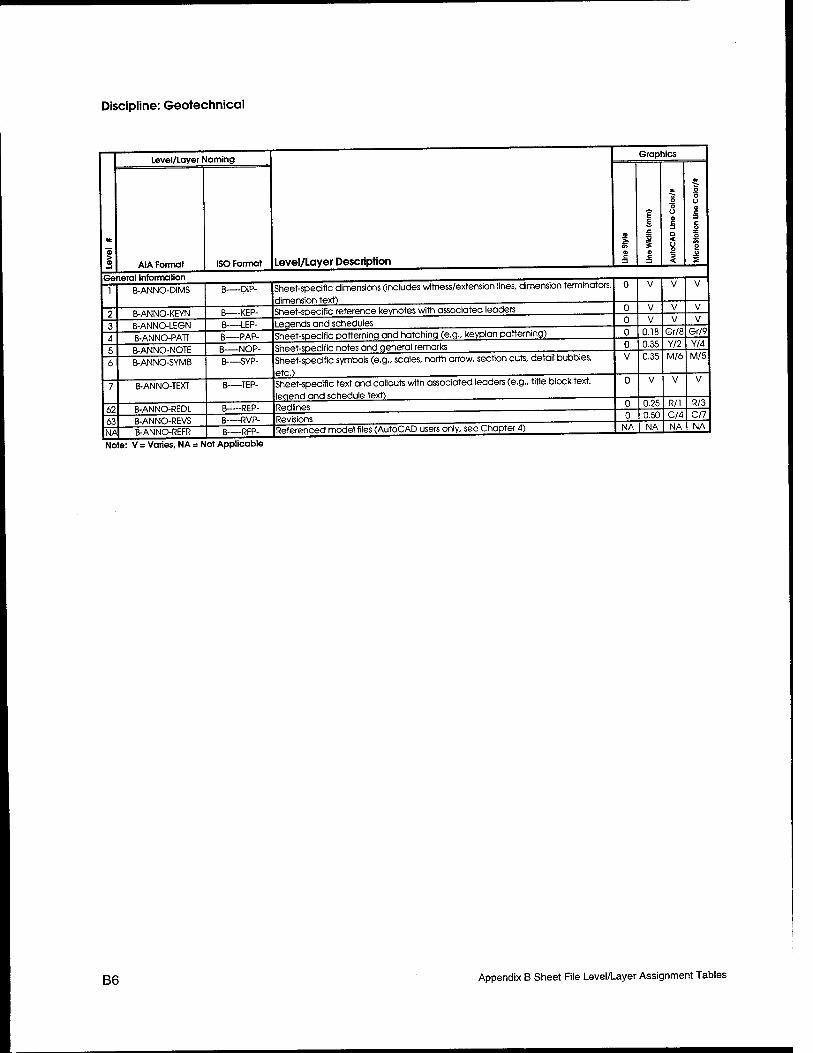
Discipline: Geotechnical
Level/Layer Naming
Level/Layer Description
Graphics
> AIA Format ISO Format
C =1
E E
1 S a 5
O O Ü a c a < o o 3 <
5 ■3 O a s c o 3= o
2 o 2
V
V
1 B-ANNO-DIMS B DIP- Sheet-specific dimensions (includes witness/extension lines, dimension Terminators,
dimension text)
u V V
0 B-ANNO-KEYN B KEP- Sheet-specific reference keynotes with associated leaders u V V
■\ B-ANNO-LEGN B-—LEP- Leqends and schedules u V V V
4 B-ANNO-PATT B PAP- Sheet-specific patterning and hatching (e.g.. keyplan patterning) u 0
U. lb 0.35
Gr/9 Y/4
b 6
B-ANNO-NOTE B-ANNO-SYMB
B NOP- B—-SYP- Sheet-specific symbols (e.g.. scales, north arrow, section cuts, detail bubbles,
etc.)
V 0.35 M/6 M/5
7 B-ANNO-TEXT B—TEP- Sheet-specific text and callouts with associated leaders (e.g., title block text, leaend and schedule text)
u V V V
ft? B-ANNO-REDL B~ -REP- Redlines u u.üb R/l R/3
63 B-ANNO-REVS B RVP- Revisions u 0.50 U4 C/7
NA B-ANNO-REFR B RFP- Referenced model files (AutoCAD users only, see Chapter 4) NA NA NA NA
Note: V = Varies, NA = Not Applicable
B6 Appendix B Sheet File Level/Layer Assignment Tables
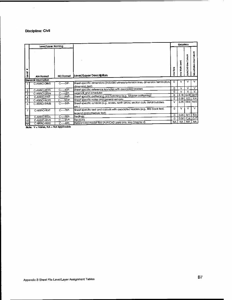
Discipline: Civil
General Information
Level/Layer Naming
Al A Formal ISO Format level/Layer Description
Graphics
62 63 NA
C-ANNO-DIMS
C-ANNO-KEYN C-ANNO-LEGN C-ANNO-PATT C-ANNO-NOTE C-ANNOSYMB
C-ANNO-TEXT
C-ANNO-REDL C-ANNO-REVS C-ANNO-REFR
C DIP-
-KEP-
Sheet-specific dimensions (includes witness/extension lines, dimension terminators,
dimension text) Sheet-specific reference keynotes with associated leaders
-LEP- -PAP- -NOP-
Sheet-specific patterning and hatching (e.g., keyplan patterning)
-SYP-
-TEP-
C—REP- -RVP- -RFP-
Legends and schedules
Sheet-specific notes and general remarks Sheet-specific symbols (e.g.. scales, north arrow, section cuts, detail bubbles,
etc.) Pl^.j ■■ —^—
Sheet-specific text and callouts with associated leaders (e.g., title block text, legend and schedule text) . Redlines Revisions Referenced model files (AutoCAD users only, see Chapter 4)
s
0.18 Gr/8 0.35 Y/2
Gr/9 Y/4
0.35 M/6 M/5
0.25 0.50
R/l C/4
R/3 C/7
NA NA NA NA
Note: V = Varies, NA = Not Applicable
Appendix B Sheet File Level/Layer Assignment Tables B7
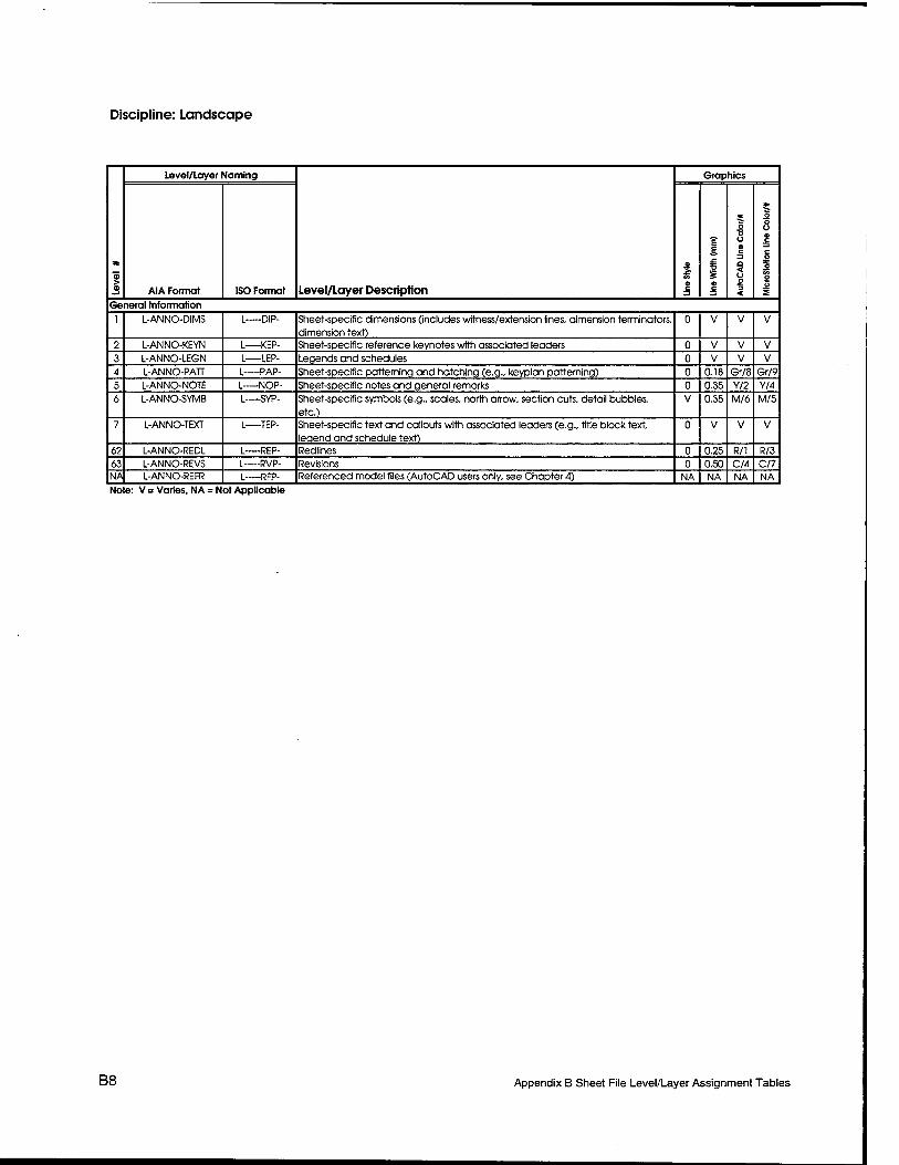
Discipline: Landscape
*
> S
Level/Layer Naming
Level/Layer Description
Graphics
AIA Format ISO Format 3
? E
«
3
2»
o o ü a c
=1 a < o o "5 <
* 5 o O a c
c o as o
2 o S
General Information 1 L-ANNO-DIMS L DIP- Sheet-specific dimensions (includes witness/extension lines, dimension terminators,
dimension text) 0 V V V
2 L-ANNO-KEYN L KEP- Sheet-specific reference keynotes with associated leaders 0 V V V 3 L-ANNO-LEGN L-—LEP- Legends and schedules 0 V V V 4 L-ANNO-PATT L—PAP- Sheet-specific patterning and hatching (e.g., keyplan patterning) 0 0.18 Gr/8 Gr/9 5 L-ANNO-NOTE L—NOP- Sheet-specific notes and general remarks 0 0.35 Y/2 Y/4 6 L-ANNO-SYMB L SYP- Sheet-specific symbols (e.g., scales, north arrow, section cuts, detail bubbles,
etc.) V 0.35 M/6 M/5
7 L-ANNO-TEXT L—TEP- Sheet-specific text and callouts with associated leaders (e.g., title block text, leaend and schedule text)
0 V V V
62 L-ANNO-REDL L REP- Redlines 0 0.25 R/l R/3 63 L-ANNO-REVS L—RVP- Revisions 0 0.50 C/4 C/7 NA L-ANNO-REFR L RFP- Referenced model files (AutoCAD users only, see Chapter 4) NA NA NA NA Note: V = Varies, NA = Not Applicable
B8 Appendix B Sheet File Level/Layer Assignment Tables
Discipline: Structural
Level/Layer Naming
AIA Format General information
ISO Format Level/Layer Description
Graphics
62 63 NA
S-ANNO-DIMS
S-ANNO-KEYN S-ANNO-LEGN S-ANNO-PATT S-ANNO-NOTE S-ANNO-SYMB
S-ANNO-TEXT
S-ANNO-REDL S-ANNO-REVS S-ANNO-REFR
S—DIP-
S KEP- S»—IEP-
Sheet-specific reference keynotes with associated leaders Legends and schedules
--PAP- S—NOP-
Sheet-speclfic patterning and hatching (e.g., keyplan patterning)
S—SYP-
Sheet-specific notes and general remarks
S—TEP-
S—REP- S RVP- S—RFP-
Sheet-specific dimensions (includes witness/extension lines, dimension terminators.
dimension text)
Sheet-specific symbols (e.g.. scales, north arrow, section cuts, detail bubbles,
etc.) Sheet-specific text and callouts with associated leaders (e.g.. title block text, legend and schedule text) Redlines Revisions Referenced model files (AutoCAD users only, see Chapter 4)
0.18 Gr/8 Gr/9 0.35 0.35
Y/2 M/6
Y/4 M/5
0.25 R/l R/3 0.50
NA NA C/4 NA
C/7 NA
Note: V = Varies. NA = Not Applicable
Appendix B Sheet File Level/Layer Assignment Tables B9
Discipline: Architectural
■5 > 3
Level/Layer Naming
Level/Layer Description
Graphics
AIA Format ISO Format
a in a c
E E
i a c 3
5 0 0 0 c 3 a < 0 0 3 <
O O O a c c 0 D
9 u S
General Information 1 A-ANNO-DIMS A DIP- Sheet-specific dimensions (includes witness/extension lines, dimension terminators,
dimension text) 0 V V V
2 A-ANNO-KEYN A KEP- Sheet-specific reference keynotes with associated leaders 0 V V V 3 A-ANNO-LEGN A LEP- Legends and schedules 0 V V V 4 A-ANNO-PATT A PAP- Sheet-specific patterning and hatching (e.g., keyplan patterning) 0 0.18 Gr/8 Gr/9 5 A-ANNO-NOTE A NOP- Sheet-specific notes and general remarks 0 0.35 Y/2 Y/4
6 A-ANNO-SYMB A SYP- Sheet-specific symbols (e.g., scales, north arrow, section cuts, detail bubbles, etc.)
V 0.35 M/6 M/5
7 A-ANNO-TEXT A—TEP- Sheet-specific text and callouts with associated leaders (e.g., title block text, leaend and schedule text)
0 V V V
62 A-ANNO-REDL A REP- Redlines 0 0.25 R/l R/3 63 A-ANNO-REVS A RVP- Revisions 0 0.50 C/4 C/7 NA A-ANNO-REFR A RFP- Referenced model files (AutoCAD users only, see Chapter 4) NA NA NA NA Note: V = Varies, NA = Not Applicable
B10 Appendix B Sheet Rle Level/Layer Assignment Tables
Discipline: Interiors
Level/Loyer Naming
AIA Format General Information
62 63
1-ANNO-DIMS
l-ANNO-KEYN l-ANNO-LEGN l-ANNO-PATT [-ANNO-NOTE l-ANNO-SYMB
l-ANNO-TEXT
l-ANNO-REDL l-ANNO-REVS
NA l-ANNO-REFR
ISO Format Level/Layer Description
Graphics
6 £
i
-DIP-
I KEP- Sheet-specific reference keynotes with associated leaders
I—LEP- I—PAP- I—NOP- I—SYP-
I TEP-
-REP- I RVP- I RFP-
Sheet-specific dimensions (includes witness/extension lines, dimension terminators.
dimension text)
Legends and schedules Sheet-specific patterning and hatching (e.g., keyplan patterning) Sheet-specific notes and general remarks Sheet-specific symbols (e.g.. scales, north arrow, section cuts, detail bubbles,
etc.) Sheet-specific text and callouts with associated leaders (e.g.. title block text, legend and schedule text) - Redlines Revisions Referenced model files (AutoCAD users only, see Chapter 4)
0.18 0.35
Gr/8 Y/2
Gr/9 Y/4
0.35 M/6 M/5
0.25 0.50
R/l C/4
R/3 C/7
NA NA NA NA
Note: V = Varies, NA = Not Applicable
Appendix B Sheet File Level/Layer Assignment Tables B11
Discipline: Fire Protection
>
Level/Layer Naming
Level/Layer Description
Graphics
AIA Format ISO Format
CO
c 3
£ £
a
o "5 o a c =] a < u o 3 <
o o u a 5 c O
o S5 o o 2
General Information
1 F-ANNO-DIMS F DIP- Sheet-specific dimensions (includes witness/extension fines, dimension terminators, dimension text)
0 V V V
2 F-ANNO-KEYN F KEP- Sheet-specific reference keynotes with associated leaders 0 V V V 3 F-ANNO-LEGN F LEP- Legends and schedules 0 V V V 4 F-ANNO-PATT F PAP- Sheet-specific patterning and hatching (e.g., keyplan patterning) 0 0.18 Gr/8 Gr/9 5 F-ANNO-NOTE F—NOP- Sheet-specific notes and general remarks 0 0.35 Y/2 Y/4 6 F-ANNO-SYMB F SYP- Sheet-specific symbols (e.g., scales, north arrow, section curs, detail bubbles,
etc.) V 0.35 M/6 M/5
7 F-ANNO-TEXJ F TEP- Sheet-specific text and callouts with associated leaders (e.g., title block text, leaend and schedule text)
0 V V V
62 F-ANNO-REDL F—- REP- Redlines 0 0.25 R/l R/3 63 F-ANNO-REVS F RVP- Revisions 0 0.50 C/4 C/7 NA F-ANNO-REFR F RFP- Referenced model files (AutoCAD users only, see Chapter 4) NA NA NA NA Note: V = Varies, NA = Not Applicable
B12 Appendix B Sheet File Level/Layer Assignment Tables

Discipline: Plumbing
Level/Layer Naming
AIA Format ISO Format
General Information
62 63
P-ANNO-DIMS
P-ANNO-KEYN
P-ANNO-LEGN
P-ANNO-PATT
P-ANNO-NOTE
P-ANNO-SYMB
P-ANNO-TEXT
P-ANNO-REDL
P-ANNO-REVS NA P-ANNO-REFR
-DIP-
-KEP-
Level/Layer Description
Graphics
-LEP- -PAP- -NOP- -SYP-
-TEP-
P—-REP- p__ RVP-
-RFP-
Sheet-specific dimensions (includes witness/extension lines, dimension terminators.
dimension text) Sheet-specific reference keynotes with associated leaders Legends and schedules Sheet-specific patterning and hatching (e.g., keyplan patterning) Sheet-specific notes and general remarks Sheet-specific symbols (e.g.. scales, north arrow, section cuts, detail bubbles,
etc.) Sheet-specific text and callouts with associated leaders (e.g.. title block text. legend and schedule text) __^ Red lines Revisions Referenced model files (AutoCAD users only, see Chapter 4)
0.18 Gr/8 Gr/9 0.35 Y/2 Y/4 0.35 M/6 M/5
0.25 R/l 0.50 C/4
R/3 C/7
NA NA NA NA
Note: V = Varies, NA = Not Applicable
Appendix B Sheet File Level/Layer Assignment Tables B13
Discipline: Mechanical
4«
> 3
Level/Layer Naming
Level/Layer Description
Graphics
AIA Format ISO Format
« «
E E
i s a c •n
4k
s O o O c =1 a < o o <
o o o 0 c C
s p
«A o o 2
General Information 1 M-ANNO-DIMS M DIP- Sheet-specific dimensions (includes witness/extension lines, dimension terminators,
dimension text) 0 V V V
2 M-ANNO-KEYN M KEP- Sheet-specific reference keynotes with associated leaders 0 V V V
3 M-ANNO-LEGN M LEP- Legends and schedules 0 V V V
4 M-ANNO-PATT M PAP- Sheet-specific patterning and hatching (e.g., keyplan patterning) 0 0.18 Gr/8 Gr/9
5 M-ANNO-NOTE M NOP- Sheet-specific notes and general remarks 0 0.35 Y/2 Y/4
6 M-ANNO-SYMB M—SYP- Sheet-specific symbols (e.g., scales, north arrow, section cuts, detail bubbles, etc.)
V 0.35 M/6 M/5
7 M-ANNO-TEXT M TEP- Sheet-specific text and calouts with associated leaders (e.g., title block text, leaend and schedule text)
0 V V V
62 M-ANNO-REDL M REP- Redlines 0 0.25 R/l R/3 63 M-ANNO-REVS M RVP- Revisions 0 0.50 C/4 C/7 NA M-ANNO-REFR M RFP- Referenced model files (AutoCAD users only, see Chapter 4) NA NA NA NA Note: V = Varies, NA = Not Applicable
B14 Appendix B Sheet File Level/Layer Assignment Tables
Discipline: Electrical
General Information
Level/Layer Naming
AIA Format
62 63 NA
E-ANNO-DIMS
E-ANNO-KEYN E-ANNO-LEGN E-ANNO-PATT E-ANNO-NOTE E-ANNO-SYMB
E-ANNO-TEXT
E-ANNO-REDl E-ANNO-REVS E-ANNO-REFR
ISO Format Level/layer Description
Graphics
E—DIP-
-KEP- Sheet-specific reference keynotes with associated leaders
-LEP- Legends and schedules
E—PAP- -NOP-
Sheet-specific patterning and hatching (e.g., keyplon patterning)
-SYP-
Sheet-specific notes and general remarks
E—-TEP-
--REP- -RVP- --RFP-
Sheet-speclfic dimensions (includes witness/extension lines, dimension terminators.
dimension text)
Sheet-specific symbols (e.g.. scales, north arrow, section cuts, detail bubbles.
etc.) Sheet-specific text and callouts with associated leaders (e.g.. title block text, legend and schedule text) , _ Redlines Revisions Referenced model files (AutoCAD users only, see Chapter 4)
0.18 Gr/8 Gr/9 0.35 Y/2 Y/4 0.35 M/6 M/5
0.25 R/l R/3 0.50
NA NA C/4 NA
C/7 NA
Note: V = Varies, NA = Not Applicable
Appendix B Sheet File Level/Layer Assignment Tables B15
Discipline: Telecommunications
■5 > 0
Level/Layer Naming
Level/Layer Description
Graphics
AIA Format ISO Format
0
a c =1
? E
i « c 3
5 0 0 9 c n a < 0 0 3 <
* 0 0 0 0 c 3 c 0
a 3» 0 0
£ General Information
1 T-ANNO-DIMS T—DIP- Sheet-specific dimensions (includes witness/extension lines, dimension terminators, dimension text)
0 V V V
2 T-ANNO-KEYN T KEP- Sheet-specific reference keynotes with associated leaders 0 V V V
3 T-ANNO-LEGN T LEP- Legends and schedules 0 V V V
4 T-ANNO-PATT T—-PAP- Sheet-specific patterning and hatching (e.g., keyplan patterning) 0 0.18 Gr/8 Gr/9
5 T-ANNO-NOTE T NOP- Sheet-specific notes and general remarks 0 0.35 Y/2 Y/4
6 T-ANNO-SYMB T—SYP- Sheet-specific symbols (e.g., scales, north arrow, section cuts, detail bubbles, etc.)
V 0.35 M/6 M/5
7 T-ANNO-TEXT T—TEP- Sheet-specific text and callouts with associated leaders (e.g., title block text, leqend and schedule text)
0 V V V
62 T-ANNO-REDL T REP- Redlines 0 0.25 R/l R/3 63 T-ANNO-REVS T—RVP- Revisions 0 0.50 C/4 C/7 NA T-ANNO-REFR T RFP- Referenced model files (AutoCAD users only, see Chapter 4) NA NA NA NA Note: V = Varies, NA = Not Applicable
B16 Appendix B Sheet File Level/Layer Assignment Tables

Appendix C Color Comparison
For more information on Screened Colors, see the section "Screening" in Chapter 3 "Graphic Concepts."
C1 Appendix C Color Comparison w
Appendix C 1 Color Comparison |
AutoCAD Color No.
MicroStation Color No.
Screened Color
1 3 2 4 3 2 4 7 5 1 6 5 7 0 8 9 9 14 10 10 Yes
11 19 Yes
12 27 Yes
13 35 Yes
14 43 Yes
15 51 Yes
16 59 Yes
17 67 18 75 19 83 Yes
20 6 21 30 22 22 23 46 24 38 25 62 26 54 27 78 28 70 29 94 30 86 31 110 32 102 33 126 34 118 35 142 36 134 37 158 38 150 39 174 40 166 41 190 42 182 43 206 44 198 45 222 46 214
Appendix C Color Comparison C3
Appendix C Color Comp arison
AutoCAD Color No.
MicroStation Color No.
Screened Color
47 238 48 230 49 251 50 20 Yes 51 28 Yes 52 36 Yes 53 44 Yes 54 52 Yes 55 60 Yes 56 68 Yes 57 76 58 84 59 92 Yes 60 100 61 108 62 116 63 124 64 132 65 140 66 148 67 156 68 164 69 172 70 180 71 188 72 196 73 204 74 212 75 220 76 228 77 236 78 244 79 252 80 11 81 26 82 18 83 42 84 34 85 58 86 50 87 74 88 66 89 90 90 82 Yes 91 106 Yes 92 98 Yes
C4 Appendix C Color Comparison
Appendix C 1 Color Comparison |
AutoCAD Color No.
MicroStation Color No.
Screened Color
93 122 Yes
94 114 Yes
95 138 Yes
96 130 Yes
97 154 98 146 99 170 Yes
100 162 101 186 102 178 103 202 104 194 105 218 106 210 107 234 108 226 109 250 110 242 111 246 112 247 113 16 114 32 115 48 116 64 117 80 118 96 119 112 120 12 121 15 122 23 123 31 124 39 125 47 126 55 127 63 128 71 129 79 130 87 Yes
131 95 Yes
132 103 Yes
133 111 Yes
134 119 Yes
135 127 Yes
136 135 Yes
137 143 138 151
Appendix C Color Comparison C5
Appendix C Color Comparison
AutoCAD Color No.
MicroStation Color No.
Screened Color
139 159 Yes 140 167 141 175 142 183 143 191 144 199 145 207 146 215 147 223 148 231 149 239 150 40 151 72 152 88 153 104 154 136 155 152 156 184 157 216 158 232 159 248 160 17 161 25 162 33 163 41 164 49 165 57 166 65 167 73 168 81 169 89 170 97 Yes 171 105 Yes 172 113 Yes 173 121 Yes 174 129 Yes 175 137 Yes 176 145 Yes 177 153 178 161 179 169 Yes 180 177 181 185 182 193 183 201 184 209
C6 Appendix C Color Comparison
Appendix C Color Comparison
AutoCAD Color No.
MicroStation Color No.
Screened Color
185 217 186 225 187 233 188 241 189 249 190 245 191 128 192 144 193 160 194 176 195 192 196 208 197 224 198 240 199 254 200 13 201 29 202 21 203 45 204 37 205 61 206 53 207 77 208 69 209 93 210 85 Yes
211 109 Yes
212 101 Yes
213 125 Yes
214 117 Yes
215 141 Yes
216 133 Yes
217 157 218 149 219 173 Yes
220 165 221 189 222 181 223 205 224 197 225 221 226 213 227 237 228 229 229 253 230 91
Appendix C Color Comparison C7
Appendix C Color Comparison
AutoCAD Color No.
MicroStation Color No.
Screened Color
231 99 232 107 233 115 234 123 235 131 236 139 237 147 238 155 239 163 240 171 241 179 242 187 243 195 244 203 245 211 246 219 247 227 248 235 249 243 250 8 Yes 251 200 Yes 252 168 Yes 253 120 Yes 254 56 Yes 255 24 Yes
C8 Appendix C Color Comparison
REPORT DOCUMENTATION PAGE Form Approved
OMB No. 0704-0188 Public reporting burden for this collection of information is estimated to average 1 hour per response, including the time for reviewing instructions, searching existing data sources, gathering and maintaining the data needed and completing and reviewing this collection of information. Send comments regarding this burden estimate or any other aspect of this collection of information, including suggestions for reducing this burden to Department of Defense, Washington Headquarters Services, Directorate for Information Operations and Reports (0704-0188), 1215 Jefferson Davis Highway, Suite 1204, Arlington VA 22202-4302 Respondents should be aware that notwithstanding any other provision of law, no person shall be subject to any penalty for failing to comply with a collection of information if it does not display a currently valid OMB control number. PLEASE DO NOT RETURN YOUR FORM TO THE ABOVE ADDRESS.
1. REPORT DATE (DD-MM-YYYY) September 2001
2. REPORT TYPE Final report
4. TITLE AND SUBTITLE
A/E/C CADD Standard, Release 2.0; Main Text and Appendices A, B, and C
6. AUTHOR(S)
The CADD/GIS Technology Center
7. PERFORMING ORGANIZATION NAME(S) AND ADDRESS(ES)
U.S. Army Engineer Research and Development Center 3909 Halls Ferry Road Vicksburg, MS 39180-6199
9. SPONSORING / MONITORING AGENCY NAME(S) AND ADDRESS(ES)
3. DATES COVERED (From - To)
5a. CONTRACT NUMBER
5b. GRANT NUMBER
5c. PROGRAM ELEMENT NUMBER
5d. PROJECT NUMBER
5e. TASK NUMBER
5f. WORK UNIT NUMBER
8. PERFORMING ORGANIZATION REPORT NUMBER
ERDC/ITLTR-01-6
10. SPONSOR/MONITOR'S ACRONYM(S)
11. SPONSOR/MONITOR'S REPORT NUMBERfS)
12. DISTRIBUTION / AVAILABILITY STATEMENT
Approved for public release; distribution is unlimited.
13. SUPPLEMENTARY NOTES
Appendix D is bound separately.
14. ABSTRACT
The "A/E/C CADD Standard Manual" has been developed by the CADD/GIS Technology Center (CGTC) to reduce redundant CADD standardization efforts within the Army, Navy, and Air Force. The manual is part of an initiative to consolidate existing CADD drafting standards and to develop data standards that address the entire life-cycle of facilities within the Department of Defense Tri-Service.
The CADD drafting standards addressed in the "A/E/C CADD Standard Manual" include presentation graphics, level/layer assignments, metric/English scales, electronic file naming, and standard symbology. As the manual evolves, it will also include nongraphic database standards that address issues such as cost engineering and specification generation. The CGTC's primary goal is to develop a CADD standard that is generic enough to operate under various CADD software packages (such as Intergraph's MicroStation and Autodesk's AutoCAD) and incorporate existing industry standards when possible.
15. SUBJECT TERMS
A/E/C CADD
CADD standards Drafting standards
16. SECURITY CLASSIFICATION OF:
a. REPORT
UNCLASSIFIED
b. ABSTRACT
UNCLASSIFIED
c. THIS PAGE
UNCLASSIFIED
17. LIMITATION OF ABSTRACT
18. NUMBER OF PAGES
176
19a. NAME OF RESPONSIBLE PERSON
19b. TELEPHONE NUMBER (include area code)
Standard Form 298 (Rev. 8-98) Prescribed by ANSI Std. 239.18