C3202 Briefing Guide (Worksheet) - T6B Driver · C3202 Briefing Guide (Worksheet) Planned Route:...
13
T-6B JPPT 1542.166A Simulator Event Briefing Guide JPPT 1542.166A C3202 C3202 Briefing Guide (Worksheet) Planned Route: Takeoff: KNSE, Rwy 32 Altitude: MOA Limits Route: KNSE, North MOA, Brewton, Evergreen, KNSE Training Device: OFT SYLLABUS NOTES: Introduce and practice the following during this block of training: Landing pattern procedures, Local departures and course rules, Local radio procedures Engine failures and malfunctions, PEL, Forced Landings and ELP’s. No strap-in required for student. Need to have gloves, kneeboard, NATOPS PCL for this event. Student will use Abbreviated Simulator checklist to expedite becoming airborne. Once airborne all applicable checklist will be conducted from the quad-fold version. Discuss a. Engine Failures Indications (EICAS Video for Flameout / Seizure) Critical Action Items (NATOPS) FTI procedures (Note: FTI refers to engine failure as Power Loss) b. Forced Landing Critical Action Items c. Ejection Critical Action Item FTI guidance
Transcript of C3202 Briefing Guide (Worksheet) - T6B Driver · C3202 Briefing Guide (Worksheet) Planned Route:...

T-6B JPPT 1542.166A
Simulator Event Briefing Guide
JPPT 1542.166A C3202
Sim
ula
tor E
vent In
stru
cto
r Guid
e
PR
IMA
RY
AN
D IN
TE
RM
ED
IAT
E M
ULT
I-SE
RV
ICE
NF
O/W
SO
TR
AIN
ING
SY
ST
EM
Gra
din
g G
uid
elin
es –
I20
01
C3202 Briefing Guide
(Worksheet) Planned Route:
Takeoff: KNSE, Rwy 32 Altitude: MOA Limits Route: KNSE, North MOA, Brewton, Evergreen, KNSE Training Device: OFT
SYLLABUS NOTES: Introduce and practice the following during this block of training: Landing pattern procedures, Local departures and course rules, Local radio procedures Engine failures and malfunctions, PEL, Forced Landings and ELP’s. No strap-in required for student. Need to have gloves, kneeboard, NATOPS PCL for this event. Student will use Abbreviated Simulator checklist to expedite becoming airborne. Once airborne all applicable checklist will be conducted from the quad-fold version. Discuss
a. Engine Failures Indications (EICAS Video for Flameout / Seizure) Critical Action Items (NATOPS) FTI procedures (Note: FTI refers to engine failure as Power Loss)
b. Forced Landing
Critical Action Items
c. Ejection Critical Action Item FTI guidance
FTC
Highlight
FTC
Highlight
FTC
Highlight
FTC
Highlight
FTC
Highlight
FTC
Highlight
FTC
Highlight
FTC
Highlight

T-6B CONTACT C3200 BLOCK
STUDENT GRADE SHEET DATE __________________ INSTRUCTOR __________________________ MEDIA: OFT VT- ________ BRIEF TIME: ________ NAME: ___________________________ EVENT:_______________
# MANEUVER MIF C3201 C3202 C3203 1 GEN KNOWLEDGE / PROCEDURES 3+ X X X 2 EMERGENCY PROCEDURES 3+ X X X 3 HEADWORK / SITUATIONAL AWARENESS 2+ X X X 4 BASIC AIRWORK 3+ X X X 5 IN-FLIGHT CHECKS / FUEL MANAGEMENT 3+ X X X 6 IN-FLIGHT PLANNING /
AREA ORIENTATION 2+ X X X
7 TASK MANAGEMENT 3+ X X X 8 COMMUNICATION 2+ X X X 9 MISSION PLANNING/BRIEFING/DEBRIEFING 2+ X X X 10 GROUND OPERATIONS 3+ X X X 11 TAKEOFF 3+ X X X 12 DEPARTURE 3+ X X X 13 G-AWARENESS / EXERCISE 2 14 TURN PATTERN 3 15 LEVEL SPEED CHANGE 3 16 SLOW FLIGHT 3 17 POWER-ON STALLS 2 18 LANDING PATTERN STALLS 2 19 EMERGENCY LANDING PATTERN STALLS 2 20 SPIN 2+ X 21 CONTACT UNUSUAL ATTITUDES 2+ X 30 SLIP 2+ X 31 POWER LOSS 2+ X X 32 PRECAUTIONARY EMERGENCY LANDING 2+ X X X 33 PEL/P 2+ X X X 34 ELP LANDING 2+ X X X 35 ARRIVAL / COURSE RULES 2+ X X 36 LANDING PATTERN 2+ X X X 37 NO FLAP LANDING 2 37 TAKEOFF FLAP LANDING 2 37 LDG FLAP LANDING 2 37 FULL STOP LANDING 2+ X 39 WAVEOFF 2+ X X SPECIAL SYLLABUS REQUIREMENT 1 X
SSR: C3203 ABORTED TAKEOFF AND AIRCRAFT DEPARTS A PREPARED SURFACE NOTE: During C3202, practice at least one pattern and landing with the TAD off. Discuss items: C3201: Engine malfunctions, PEL, and ELP. C3202: Engine failures, forced landing, and ejection. C3203: Crosswind takeoff/touch-and-go/full-stop landings, aborted takeoff, and aircraft departs a prepared surface. DEPART ______________ ARRIVE ______________ SIDE # ______________ SIM TIME ___________
JPPT 1542.166A Rev 5/16/2013
FTC
Highlight
FTC
Highlight
FTC
Highlight
FTC
Highlight
FTC
Highlight
FTC
Highlight
FTC
Highlight
FTC
Highlight
FTC
Highlight
FTC
Highlight
FTC
Highlight
FTC
Highlight
FTC
Highlight
FTC
Highlight
FTC
Highlight
FTC
Highlight
FTC
Highlight
FTC
Highlight
FTC
Highlight
FTC
Highlight
FTC
Highlight
FTC
Highlight
Change 4 3-7
AIR FORCE TO 1T-6B-1NAVY (NAVAIR) A1-T6BAA-NFM-100
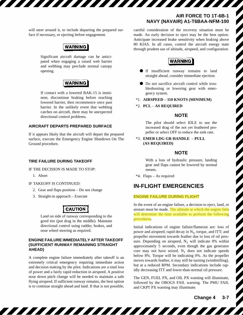
will steer around it, to include departing the prepared sur-face if necessary, or ejecting before engagement.
Significant aircraft damage can be antici-pated when engaging a raised web barrierand webbing may preclude normal canopyopening.
If contact with a lowered BAK-15 is immi-nent, discontinue braking before reachinglowered barrier, then recommence once pastbarrier. In the unlikely event that webbingcatches on aircraft, there may be unexpecteddirectional control problems.
AIRCRAFT DEPARTS PREPARED SURFACE
If it appears likely that the aircraft will depart the preparedsurface, execute the Emergency Engine Shutdown On TheGround procedure.
TIRE FAILURE DURING TAKEOFF
IF THE DECISION IS MADE TO STOP:
1. Abort
IF TAKEOFF IS CONTINUED:
2. Gear and flaps position – Do not change
3. Straight-in approach – Execute
Land on side of runway corresponding to thegood tire (put drag in the middle). Maintaindirectional control using rudder, brakes, andnose wheel steering as required.
ENGINE FAILURE IMMEDIATELY AFTER TAKEOFF (SUFFICIENT RUNWAY REMAINING STRAIGHT AHEAD)
A complete engine failure immediately after takeoff is anextremely critical emergency requiring immediate actionand decision making by the pilot. Indications are a total lossof power and a fairly rapid reduction in airspeed. A positivenose down pitch change will be needed to maintain a safeflying airspeed. If sufficient runway remains, the best optionis to continue straight ahead and land. If that is not possible,
careful consideration of the recovery situation must bemade. An early decision to eject may be the best option.Anticipate increased brake sensitivity when braking above80 KIAS. In all cases, control the aircraft energy statethrough prudent use of altitude, airspeed, and configuration.
● If insufficient runway remains to landstraight ahead, consider immediate ejection.
● Do not sacrifice aircraft control while trou-bleshooting or lowering gear with emer-gency system.
*1. AIRSPEED – 110 KNOTS (MINIMUM)
*2. PCL – AS REQUIRED
NOTEThe pilot should select IDLE to use theincreased drag of the not yet feathered pro-peller or select OFF to reduce the sink rate.
*3. EMER LDG GR HANDLE – PULL(AS REQUIRED)
NOTEWith a loss of hydraulic pressure, landinggear and flaps cannot be lowered by normalmeans.
*4. Flaps – As required
IN-FLIGHT EMERGENCIES
ENGINE FAILURE DURING FLIGHT
In the event of an engine failure, a decision to eject, land, orairstart must be made. The altitude at which the engine failswill determine the time available to perform the followingprocedures.
Initial indications of engine failure/flameout are: loss ofpower and airspeed; rapid decay in N1, torque, and ITT; andpropeller movement towards feather due to loss of oil pres-sure. Depending on airspeed, N1 will indicate 0% withinapproximately 5 seconds, even though the gas generatorcore may not have seized. N1 does not indicate speedsbelow 8%. Torque will be indicating 0%. As the propellermoves towards feather, it may still be turning (windmilling),but at a reduced RPM. Secondary indications include rap-idly decreasing ITT and lower-than-normal oil pressure.
The GEN, FUEL PX, and OIL PX warning will illuminate,followed by the OBOGS FAIL warning. The PMU FAILand CKPT PX warning may illuminate.
FTC
Highlight
FTC
Highlight

3-8 Change 2
AIR FORCE TO 1T-6B-1NAVY (NAVAIR) A1-T6BAA-NFM-100
Sufficient hydraulic pressure may not be available to oper-ate the gear and flaps as the engine spools down. Gear andflaps will remain in the last selected position at the time ofengine failure. Gear may indicate unsafe or in transit ifoperation is attempted at time of engine failure.
Initial reaction to any malfunction at low altitude should beto trade excess airspeed for altitude. Higher altitude trans-lates directly to additional terrain clearance for ejection,additional glide range to reach a suitable landing, or addi-tional time to achieve an airstart.
The pilot should zoom to eject if the engine has failed andthere are no suitable landing options and a restart is not war-ranted (insufficient altitude or type of failure precludesrestart). The zoom to eject is accomplished by pulling up toa 20° climb angle (if able) and ejecting before a sink ratedevelops. Zoom to eject allows the pilot to add 200 feet ofaltitude increase above the altitude gain noted in the zoomchart due to not pushing over. If the decision to eject is notimmediately obvious, follow the zoom to climb procedure.
If attempting an airstart or positioning to land, the followingprocedures should be followed. Above 150 KIAS, initiate azoom climb using a 2 G pull up to a 20° climb angle untilapproaching the desired glide airspeed (use approximately20 KIAS lead point) and then initiating a 0 to +0.5 G push-over to capture desired glide airspeed. Below 150 KIAS, thebenefits of a zoom climb are negligible. The recommendedprocedure is to perform a constant altitude deceleration todesired glide airspeed. Figure 3-2 shows low altitude zoomcapability at 200 KIAS and Figure 3-3 shows low altitudezoom capability at 250 KIAS.
Zoom capability at 200 knots will vary from 603 to 915 feetof altitude gained. Zoom capability at 250 knots will varyfrom 1180 to 1576 feet of altitude gained. The lower num-bers are for light aircraft at low pressure altitudes and thehigher numbers are for heavier aircraft at higher pressurealtitudes. The zoom to eject procedure will gain an addi-tional 200 feet of altitude.
NOTE● Zoom results with an engine still producing a
usable torque (>6%) will be several hundredto several thousand feet higher in altitudegained.
● Each low altitude zoom capability chartdepicted in Figure 3-2, Figure 3-3, and Fig-ure 3-4 represents a no engine condition.Each chart assumes the pilot will not per-form any action prior to actual engine fail-ure.
To use the low altitude zoom charts, proceed as follows:
EXAMPLE 1 (airspeed 200 KIAS, Figure 3-2): Enter chartwith initial conditions of weight, altitude, and airspeed(6000 lbs, 6000 feet, and 200 KIAS in the example). Tracevertically up from weight (A) and interpolate between thepressure altitude guidelines, as required, to determine theintersection of these values (B). Trace back to the left handmargin to determine the altitude gain (C) (843 feet). There-fore, a 2 G zoom from 200 KIAS and 6000 feet with a 0 to+0.5 G pushover to capture 125 KIAS glide airspeed shouldresult in a final altitude of 6843 feet.
EXAMPLE 2 (airspeed 250 KIAS, Figure 3-3): Enter chartwith initial conditions of weight, altitude, and airspeed(6000 lbs, 6000 feet, and 250 KIAS in the example). Tracevertically up from weight (A) and interpolate between thepressure altitude guidelines, as required, to determine theintersection of these values (B). Trace back to the left handmargin to determine the altitude gain (C) (1522 feet). There-fore, a 2 G zoom from 250 KIAS and 6000 feet with a 0 to+0.5 G pushover to capture 125 KIAS glide airspeed shouldresult in a final altitude of 7522 feet.
Figure 3-4 provides a tabular listing of altitude gains basedon a variety of conditions at 200 and 250 KIAS.
If a decision is made to land, enter the emergency landingpattern at high key, if possible. If high key entry is not pos-sible, it may be possible to intercept the pattern at a loweraltitude. Glide performance will be considerably reduceduntil the propeller is feathered. Figure 3-5 shows maximumglide information.
*1. ZOOM/GLIDE – 125 KNOTS (MINIMUM)
NOTE● Crosscheck N1 against other engine indica-
tions to assess condition of engine and deter-mine if an airstart is warranted. At 125KIAS, an engine which has flamed out willrotate below 8% N1 and indicate 0% N1. Theengine oil pressure indicator may display oilpressures up to 4 psi with an N1 of 0%.
● If experiencing uncommanded powerchanges/loss of power/uncommanded pro-peller feather or compressor stalls, refer toappropriate procedure.
*2. PCL – OFF
NOTEPropeller will not feather unless the PCL isfully in OFF.
*3. INTERCEPT ELP
FTC
Highlight

3-14 Change 2
AIR FORCE TO 1T-6B-1NAVY (NAVAIR) A1-T6BAA-NFM-100
● If a suitable landing surface is available, turnimmediately to intercept the nearest suitablepoint on the ELP. Any delay could result ininsufficient gliding distance to reach a land-ing surface.
● Do not delay decision to eject below 2000feet AGL.
*4. Airstart - Attempt if warranted
Airstart procedure is not recommendedbelow 2000 feet AGL, as primary attentionshould be to eject or safely recover the air-craft.
IF CONDITIONS DO NOT WARRANT AN AIRSTART:
*5. FIREWALL SHUTOFF handle - Pull
*6. Execute Forced Landing or Eject
AIRSTART
Three airstart procedures are approved for this aircraft:PMU NORM; PMU OFF; and Immediate Airstart (PMUNORM). The status of the PMU dictates the type of airstartattempted. All airstarts are starter assisted.
Use this procedure if engine failure was not due to fire ormechanical failure. Airstarts may be attempted at any alti-tude and airspeed, although airstarts have only been demon-strated at 20,000 feet MSL and below, as depicted in Figure3-6.
If the engine fails during flight at low altitude, an immediateejection should be considered if sufficient altitude and air-speed are not available for a successful restart. If excess air-speed is available, exchange airspeed for altitude to allowmore time to accomplish the AIRSTART procedures.Restart should be attempted immediately. The first action,PCL OFF, is critical. This will feather the propeller, reducethe aircraft drag and increase glide distance. Attempt aPMU NORM airstart if PMU FAIL warning is not illumi-nated. The PMU OFF (Manual) airstart is recommendedonly for PMU malfunctions, since pilot workload isincreased with manually metering fuel with the PCL duringthe start. If the airstart is successful, useful power will beavailable after 40 seconds from starter engagement.
In general, trim the aircraft to the desired airspeed andensure sufficient altitude is available prior to the airstart.
The extra drag during airstart attempts will cause a greaterdescent rate than 1350 to 1500 feet/minute. Approximately1200 feet of altitude will be lost during an airstart attemptperformed at the best glide speed of 125 KIAS. Approxi-mately 40 seconds will be required to complete the startingsequence. The higher the altitude, and the slower the air-speed, the warmer the starting ITT peak temperature. As thestart progresses, the pilot’s attention must be focused on fuelflow, ITT and N1 throughout the starting sequence. Afterthe start is complete, the critical step is setting the starterswitch to NORM to allow the generator to come online.
Consideration should be given to notattempting an airstart if on a minimum glideprofile to an airfield, since repeated airstartattempts will result in excessive altitude loss.
The PMU NORM airstart is considered the primary methodsince it is less sensitive to the rate of PCL movement, andcooler starts can be expected at lower airspeeds. This proce-dure depends upon pilot action to correctly position the PCLand critical switches.
If the PMU FAIL warning is illuminated, a PMU OFFairstart is required. Critical steps during this starting proce-dure include setting the PMU switch to OFF and turning theignition switch ON. The most critical pilot action during thestart is PCL movement while monitoring fuel flow, ITT andN1 acceleration. Advancing the PCL too rapidly during thestart causes high ITT and may overtemp the engine.Advancing the PCL too slowly may cause N1 to roll backwith decreasing ITT.
PMU NORM AIRSTART
The PMU NORM airstart procedure will provide the leastcomplicated airstart. Refer to PMU OFF airstart if PMUFAIL message is present.
Airstart attempts outside of the airstart enve-lope may be unsuccessful or result in engineovertemperature. Consideration should begiven to ensure airstarts are attempted withinthe airstart envelope (125-200 KIAS for sealevel to 15,000 feet, or 135-200 KIAS for15,001 to 20,000 feet).
1. PCL – OFF

CHAPTER SEVEN PRIMARY CONTACT
7-16 EMERGENCY PROCEDURES
f. Failure to reduce power to idle during landing phase of PEL.
705. ENGINE FAILURE DURING FLIGHT (POWER LOSS)
1. Description. A complete engine failure or insufficient power available to execute a PEL
may occur at any airspeed, altitude or configuration. Fly (glide) to intercept the ELP profile
while simultaneously executing the appropriate procedures. Identify the nearest suitable
airfield and safely maneuver the aircraft to intercept the ELP. Arrive at high key aligned with
the landing runway. If high key cannot be reached, intercept profile at some point on the ELP
(low key, base key, final). Below 2000 feet AGL, make a timely decision to continue or eject.
2. General. The below guidance is geared towards an engine failure, airstart attempt not
warranted and will guide you to a forced landing or ejection situation. If an airstart is
warranted, and is successful, the end result of your procedures will direct you to execute a
PEL. Refer to PEL procedures contained within section 704 of this chapter.
Carefully manage your energy state to arrive at high key on or slightly above altitude. Do not
unnecessarily dissipate energy quickly with a failed engine. Use the extra time to formulate a
plan that will maximize the possibility for success.
The Engine Failure During Flight procedures in the T-6B NATOPS Flight Manual offers an
organized approach to recovery with an engine failure in flight. If the engine can’t be restored
to normal operations, you will need to decide whether to use the ELP and recover via a Forced
Landing, or Eject if no suitable landing site is within reach using DEGA.
3. Procedures. After properly analyzing the malfunction as an engine failure, take
proper action by executing the first four memory critical action items without delay.
a. ZOOM/GLIDE - 125 KIAS (MINIMUM). Above 150 KIAS, zoom to capture
125 KIAS minimum. Below 150 KIAS, slow to 125 KIAS minimum as required. At
high altitudes, smoothly decelerate to the 125 KIAS descent attitude to trade excess
airspeed for glide distance. Raise landing gear, flaps and speed brake as soon as
possible as retraction may not be possible as the engine spools down. Get to your
best glide speed in a trimmed flight condition.
NOTE
Crosscheck N1 against other instruments to assess condition of
engine and determine if an airstart is warranted. VERBALIZE the
engine indications which may include Torque, ITT, N1, Np, Oil and
Hydraulic pressure. Your instructor will verify indications and then
give simulated engine indications and any EICAS messages that
may apply. At 125 KIAS, an engine which has flamed out will
rotate below 8% N1 and indicated 0% N1. The engine oil pressure
indicator may display oil pressures up to 4 psi with an N1 of 0%
Cubic
Highlight
Cubic
Highlight

PRIMARY CONTACT CHAPTER SEVEN
EMERGENCY PROCEDURES 7-17
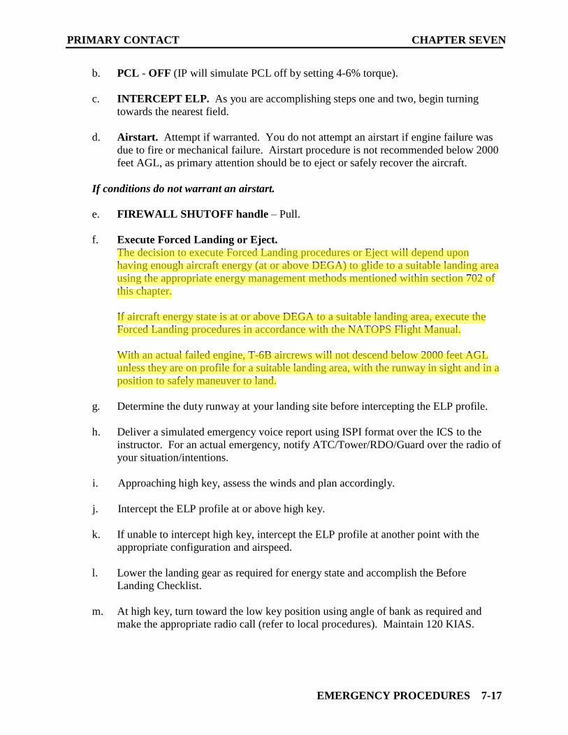
b. PCL - OFF (IP will simulate PCL off by setting 4-6% torque).
c. INTERCEPT ELP. As you are accomplishing steps one and two, begin turning
towards the nearest field.
d. Airstart. Attempt if warranted. You do not attempt an airstart if engine failure was
due to fire or mechanical failure. Airstart procedure is not recommended below 2000
feet AGL, as primary attention should be to eject or safely recover the aircraft.
If conditions do not warrant an airstart.
e. FIREWALL SHUTOFF handle – Pull.
f. Execute Forced Landing or Eject.
The decision to execute Forced Landing procedures or Eject will depend upon
having enough aircraft energy (at or above DEGA) to glide to a suitable landing area
using the appropriate energy management methods mentioned within section 702 of
this chapter.
If aircraft energy state is at or above DEGA to a suitable landing area, execute the
Forced Landing procedures in accordance with the NATOPS Flight Manual.
With an actual failed engine, T-6B aircrews will not descend below 2000 feet AGL
unless they are on profile for a suitable landing area, with the runway in sight and in a
position to safely maneuver to land.
g. Determine the duty runway at your landing site before intercepting the ELP profile.
h. Deliver a simulated emergency voice report using ISPI format over the ICS to the
instructor. For an actual emergency, notify ATC/Tower/RDO/Guard over the radio of
your situation/intentions.
i. Approaching high key, assess the winds and plan accordingly.
j. Intercept the ELP profile at or above high key.
k. If unable to intercept high key, intercept the ELP profile at another point with the
appropriate configuration and airspeed.
l. Lower the landing gear as required for energy state and accomplish the Before
Landing Checklist.
m. At high key, turn toward the low key position using angle of bank as required and
make the appropriate radio call (refer to local procedures). Maintain 120 KIAS.
Cubic
Highlight
Cubic
Highlight
Cubic
Highlight
Cubic
Highlight
Cubic
Highlight
Cubic
Highlight
Cubic
Highlight
Cubic
Highlight
Cubic
Highlight

CHAPTER SEVEN PRIMARY CONTACT
7-18 EMERGENCY PROCEDURES
n. Approaching low key, vary the angle of bank as necessary so as to arrive at a 2/3
wingtip distance abeam the intended point of landing. Level the wings momentarily
to check your position abeam.
o. At low key, set TO flaps (if on profile) and perform the low key voice report (IAW
local SOP). Lower flaps no sooner than low key. If flaps are delayed because of low
energy state, use caution in the final turn because of increased stall speed. Do not
slow below 120 KIAS.
p. Assess energy state approaching the base key position and determine if a safe landing
can be made. If a safe landing is unlikely, EJECT (actual engine failure) or
WAVEOFF (simulated engine failure).
q. Continue the turn towards the base key position. Vary angle of bank as necessary to
arrive at a proper base key position (600-800 feet AGL, 120 KIAS).
r. Check and report, “Gear down, flaps TO (or LDG as required), speed brake retracted,
Before Landing Checklist complete.”
s. Decelerate toward 110 KIAS minimum after rolling out on final. Maintain 110 KIAS
minimum on final until commencing the landing transition. Make an ICS call IAW
local procedures.
t. Unless directed by the IP, power will remain at 4-6% throughout the flare to simulate
a feathered prop. Anticipate longer flare and touchdown due to decreased drag.
During simulated engine failure training, if touchdown will occur past the first 1/3
of the runway, WAVEOFF.
4. Common Errors.
a. Not getting the aircraft into a trimmed 125 KIAS glide speed.
b. Failure to compare actual and desired position and energy.
c. Improper position at high key (aircraft not aligned).
d. Excessive or insufficient bank angle at high key resulting in improper low key
spacing.
e. Premature configuration. For example, TO flaps lowered at low key with
insufficient energy on profile.
f. Not trimming throughout the ELP profile.
g. Failure to anticipate or correct for wind.
Cubic
Highlight

Change 1 3-43
AIR FORCE TO 1T-6B-1NAVY (NAVAIR) A1-T6BAA-NFM-100
LIFE RAFT OPERATION
1. When clear of parachute canopy, retrieve the life raftby locating the drop line and pulling the raft to you.
2. Position the raft so boarding will be on the same sideas the CO2 bottle.
3. Grasp raft and forcibly push below waist.
4. Use boarding handles, pull into raft and turn towardsseated position.
5. Locate sea anchor and deploy.
6. Retrieve rucksack.
7. Pull canopy over shoulders.
8. Use integral bailer to remove water from inside liferaft as follows:
a. Make sure funnel is not twisted.
b. Put funnel end of integral bailer in water and liftfunnel to allow water to run out through tube.
c. Repeat (b) until no water remains in life raft.
d. Use bailing sponge to dry floor and squeeze waterout into funnel.
e. When there is no more water in life raft, twist inte-gral bailer three complete turns.
f. Tie integral bailer to floor loop patch with cordusing bowline knot.
9. Feed antenna of emergency transmitter through sleevein raft canopy.
10. Close raft canopy and attach edges with touch-and-close fastener strips and press studs.
11. Pull raft hood canopy over face and attach touch-and-close patches.
RESCUE
If picked up by rescue helicopter with no rescue swimmerdeployed, the following procedures should be followed:
1. Stow or discard loose gear and roll out on right side ofraft (side with CO2 bottle).
2. Ensure helmet visor has been lowered and swim awayfrom raft.
3. Disconnect lower KOCH fittings after rescue strop(horse collar) has been lowered.
● To allow discharge of static electricity andprevent electrical shock, avoid touching res-cue device until it has made contact withwater/ground.
● To avoid severe injury, keep hands clear ofhook and ring assemblies during hoisting.
● Under no circumstances should survivorsattempt to assist their entrance into helicop-ter or move from rescue device until helicop-ter aircrewman assists them to a seat in theaircraft.
Use the following procedures for use of the rescue strop(horse collar):
1. Grasp free end of rescue strop.
2. Encircle body with rescue strop and roll into rescuestrop.
3. Attach free end of rescue strop to large hook.
4. Make sure rescue strop is above waist and high onback.
5. Wrap arms around rescue strop.
6. Keep head down and to left; give thumbs up signal tohelo-hoist operator.
7. Cross feet after clear of water.
LANDING EMERGENCIES
EMERGENCY LANDING PATTERN
Figure 3-10 shows a typical emergency landing pattern(ELP). Anytime system/engine malfunctions jeopardizecontinued operation of the engine, use Precautionary Emer-gency Landing or Forced Landing procedures to recover theaircraft using the ELP profile. Adjust the presented patternfor existing altitude, airspeed, and configuration as well assurface winds. This pattern should only be performed to asuitable landing area (hard surface runway, taxiway, orunder/overrun).
FORCED LANDING
Forced Landing procedures should be executed while inter-cepting or maintaining the ELP profile to recover the air-craft when the engine is not available, and an airstart is notattempted or unsuccessful.
● Landing distance will increase with the pro-peller feathered.
● Landing on an unprepared surface may causestructural damage making it impossible toopen the canopy or fracture it using the CFS.
FTC
Highlight
FTC
Highlight

3-46 Change 1
AIR FORCE TO 1T-6B-1NAVY (NAVAIR) A1-T6BAA-NFM-100
Engine failure or shutdown will completelydisable the bleed air system. Depending onenvironmental conditions, this may causesignificant canopy icing and/or fogging, andseverely hamper visibility, especially fromthe rear cockpit.
● Ejection is recommended if a suitable land-ing area is not available. If circumstancesdictate an emergency landing and ejection isnot possible or the ejection system malfunc-tions, the pilot may perform an ELP to anunprepared surface or ditch the aircraft. Theaircraft structure can survive either type offorced landing; however, the risk of injuryincreases significantly due to crash loads andthe complexity of ground or water egress.
● Inducing yaw (side slipping) with a knownengine/oil malfunction could result inimpaired windshield visibility due to oilleakage spraying onto the windshield.
*1. Airspeed – 125 KIAS prior to extending landing gear
*2. EMER LDG GR handle – Pull (as required)
If landing on an unprepared surface or ditch-ing, do not extend the landing gear. Flapswill not be available without emergency gearextension.
NOTENormal safe indications with electricalpower, when the emergency extension sys-tem has been used to lower the gear, are twogreen main gear lights, two red main doorlights, green nose gear light, and red light inhandle.
*3. Airspeed – 120 KIAS minimum until interceptingfinal; 110 KIAS minimum on final
*4. Flaps – As required
NOTE● Selecting either TO or LDG flaps will extend
the flaps to the commanded position if thelanding gear has been extended using theemergency extension system and if batterypower is available.
● Landing gear/flap retraction is not possiblewhen the emergency extension system hasbeen used.
● Nose wheel steering is unavailable with aninoperative engine. Maintain directional con-trol with rudder and differential braking.
ACCOMPLISH THE FOLLOWING AS CONDITIONSPERMIT:
5. Distress call – Transmit
6. ELT switch – As required
NOTEActivating the ELT at a higher altitude willtransmit emergency signal for a longer dis-tance and could aid in rescue/recovery.
7. Transponder – 7700 (as required)
8. Harness – Locked (BOTH)
9. Emergency Ground Egress procedure – Execute (asrequired)
LANDING ON UNPREPARED SURFACE
This procedure is used if ejection is not possible or if theejection system malfunctions. A circular pattern will pro-vide the best observation of surface condition, wind speedand direction. Select a landing area, preferably free ofobstacles, of adequate size to accommodate the aircraft.Smooth, cultivated fields are best; swamps, boggy ground,shallow lakes and forested areas should be avoided if possi-ble. Once the condition of the terrain has been observed anda landing area selected, follow the Emergency Landing Pat-tern.
● Landing on an unprepared surface is not rec-ommended.
● To avoid causing the aircraft to tumble orcartwheel on touchdown, do not extend land-ing gear or flaps if landing on an unpreparedsurface.
FTC
Highlight

Change 1 3-37
AIR FORCE TO 1T-6B-1NAVY (NAVAIR) A1-T6BAA-NFM-100
EJECTION
● If the seat becomes unlocked from the cata-pult and slides partially up the rails or com-pletely out of the cockpit, ejection and/orparachute deployment is still possible, butthe ejection handle must be pulled followedby activation of the manual override (MOR)handle. Under these circumstances, low alti-tude ejection capabilities are compromised.
● If increased pressure in the mask is not feltafter a high altitude ejection prior to seat sep-aration, the pilot should make attempts tofirmly pull the green ring because it is possi-ble the ejection sequence may not fully acti-vate the emergency oxygen cylinder. Severalattempts may be required to fully activate thesystem using the green ring.
CONTROLLED EJECTION
During any low altitude ejection, the chances for successfulejection can be greatly increased by pulling up to exchangeairspeed for altitude if conditions permit. Avoid ejectingwith a sink rate, which will degrade seat performance. Fig-ure 3-7 shows ejection seat initiation, Figure 3-8 shows the
normal ejection sequence, and Figure 3-9 shows the ejectionenvelope.
PERFORM AS TIME AND CONDITIONS PERMIT:
1. Notify crewmember of decision to eject (BOTH)
2. Altitude – 2000 feet AGL minimum (recommended)
● If the aircraft is not controllable, ejectionmust be accomplished regardless of speed,altitude, or attitude since immediate ejectionoffers the best opportunity for survival.
● Recommended minimum altitudes for ejec-tion are 2000 feet AGL for controlled ejec-tion and 6000 feet AGL for uncontrolledejection.
● The possibility of safe ejection is greatlyimproved by making the decision to ejectearly, and with sufficient airspeed and alti-tude. Although the ejection seat is capable ofejection at zero altitude and zero airspeed, orwith sink rates to 10,000 feet per minute, donot postpone the decision to eject. Variablessuch as pilot reaction time, aircraft attitude,airspeed, and sink rate can significantlyaffect minimum safe ejection altitude.
Figure 3-7. Ejection Initiation
PT03D 981069AA.AI
GRIP THE EJECTION HANDLE WITH THE THUMB AND AT LEAST TWO FINGERS OF EACH HAND, PALMS TOWARD BODY AND ELBOWS CLOSE TO BODY.
GRIP HANDLE WITH STRONG HAND. WITH PALMS TOWARD BODY, GRIP WRIST OF STRONG HAND WITH OTHER HAND, PALMS TOWARD BODY AND ELBOWS CLOSE TO BODY.
PULL HANDLE SHARPLY UP AND TOWARD ABDOMEN, KEEPING ELBOWS IN. ENSURE THAT HANDLE IS PULLED TO END OF TRAVEL.
METHOD A METHOD B EJECT

Change 4 3-41
AIR FORCE TO 1T-6B-1NAVY NAVAIR A1-T6AAA-NFM-100
When ejecting over mountainous terrainexceeding 8000 feet MSL, the manual over-ride (MOR) handle should be used to manu-ally separate from the seat and deploy theparachute.
3. Airspeed - 125 to 180 KIAS (recommended)
4. Distress call - Transmit
5. Transponder - 7700
6. Loose equipment - Stow (BOTH)
7. Visor - Down (BOTH)
8. Oxygen mask and helmet - Fastened and tight, chinstrap fastened (BOTH)
Failure to release emergency oxygen hosefrom elastic sidewall strap may result in lossof emergency oxygen system during ejection.
9. Leg restraint garters - Check (BOTH)
10. Harness - Locked (BOTH)
11. SSK deployment knob - As required (BOTH)
12. Turn aircraft toward uninhabited area
13. PCL - OFF
14. Assume proper position:
a. Head back firmly against headpad
b. Shoulders and back against seat back
c. Elbows close to body
d. Legs flat on seat pad
e. Legs extended, but not rigid
15. Execute EJECT
EJECT* 1. EJECTION HANDLE - PULL (BOTH)
• To avoid injury, grasp handle and pullsharply toward abdomen, keeping elbowsagainst the body.
• The emergency escape system incorporatesan explosive canopy fracturing system. Theforce of detonation blows numerous shardsand small fragments outward from the can-
opy and into the cockpit. Some metallic frag-ments may be extremely hot and may causeburns upon contact with the skin. Aircrewshould ensure exposed skin is covered, theoxygen mask is on, and visor is down prior toejection or actuating the CFS system to pre-vent injury from shards and hot fragments.
• When ejecting over mountainous terrainexceeding 8000 feet MSL, the manual over-ride (MOR) handle should be used to manu-ally separate from the seat and deploy theparachute.
NOTEIf ejecting at low speed, one or both sets ofrisers may remain velcroed together follow-ing seat separation. This may create a slightincrease in descent rate and/or an uncom-manded turn. Manually separate the risers iftime permits. The steering lines (toggles) arelocated on the backside of each of the frontrisers. To counter any uncommanded turns,unstow the opposite steering line or use risersfor controllability.
USE OF TERRAIN CLEARANCE CHARTS
Terrain clearance performance as illustrated in Figure 3-9has been calculated to show the minimum terrain clearancein feet above ground level (AGL) for safe ejection of aheavy, front seat occupant in a dual sequenced ejection. Noallowance is made for crew reaction time. The minimumheights shown were calculated for standard sea level atmo-spheric conditions; add 1% additional terrain clearance forevery 1000 feet MSL of aircraft altitude. The chart does not include the effects of the altitude sensing device and G-lim-iting devices, both of which will delay parachute deploymentabove 8000 feet MSL by up to approximately 2 minutes at35,000 feet. The impact of this delay does not change the rec-ommended minimum altitudes for ejection.
A conservative minimum terrain clearance can be obtainedby combining the minimum terrain clearances for each of theindividual conditions.
POST EJECTION PROCEDURES1. Inspect canopy - Carefully inspect canopy and suspen-
sion lines for damage and/or malfunctions
2. (I) Inflate LPU - Locate toggles and pull down to waist
3. (R) Release raft by pulling the SSK manual releasehandle - As required
PRIMARY CONTACT CHAPTER SEVEN
EMERGENCY PROCEDURES 7-17
b. PCL - OFF (IP will simulate PCL off by setting 4-6% torque).
c. INTERCEPT ELP. As you are accomplishing steps one and two, begin turning
towards the nearest field.
d. Airstart. Attempt if warranted. You do not attempt an airstart if engine failure was
due to fire or mechanical failure. Airstart procedure is not recommended below 2000
feet AGL, as primary attention should be to eject or safely recover the aircraft.
If conditions do not warrant an airstart.
e. FIREWALL SHUTOFF handle – Pull.
f. Execute Forced Landing or Eject.
The decision to execute Forced Landing procedures or Eject will depend upon
having enough aircraft energy (at or above DEGA) to glide to a suitable landing area
using the appropriate energy management methods mentioned within section 702 of
this chapter.
If aircraft energy state is at or above DEGA to a suitable landing area, execute the
Forced Landing procedures in accordance with the NATOPS Flight Manual.
With an actual failed engine, T-6B aircrews will not descend below 2000 feet AGL
unless they are on profile for a suitable landing area, with the runway in sight and in a
position to safely maneuver to land.
g. Determine the duty runway at your landing site before intercepting the ELP profile.
h. Deliver a simulated emergency voice report using ISPI format over the ICS to the
instructor. For an actual emergency, notify ATC/Tower/RDO/Guard over the radio of
your situation/intentions.
i. Approaching high key, assess the winds and plan accordingly.
j. Intercept the ELP profile at or above high key.
k. If unable to intercept high key, intercept the ELP profile at another point with the
appropriate configuration and airspeed.
l. Lower the landing gear as required for energy state and accomplish the Before
Landing Checklist.
m. At high key, turn toward the low key position using angle of bank as required and
make the appropriate radio call (refer to local procedures). Maintain 120 KIAS.
Cubic
Highlight