C-Ware DSLAM Uplink Networking Line Card Application User ... · PDF fileC-Ware DSLAM Uplink...
24
C-Ware DSLAM Uplink Line Card Application User Guide Page 1 of 24 _______________________________________________________________________ C-Ware DSLAM Uplink Networking Line Card Application User Guide CALDSLAM-UG/D Version 1.0, 11/25/2002
Transcript of C-Ware DSLAM Uplink Networking Line Card Application User ... · PDF fileC-Ware DSLAM Uplink...

C-Ware DSLAM Uplink Line Card Application User Guide
Page 1 of 24
_______________________________________________________________________
C-Ware DSLAM Uplink NetworkingLine Card Application
User Guide
CALDSLAM-UG/DVersion 1.0, 11/25/2002
C-Ware DSLAM Uplink Line Card Application User Guide
Page 2 of 24
1. INTRODUCTION 3
1.1 PURPOSE OF DOCUMENT 31. 2 SOFTWARE ARCHITECTURE OVERVIEW 31.3 DATA FLOW OVERVIEW 41.3.1 UPSTREAM TRAFFIC 41.3.2 DOWNSTREAM TRAFFIC 41.3.3 HOST-BOUND TRAFFIC 41.3.4 HOST-GENERATED TRAFFIC 4
2. COMPONENT DESIGN 8
2.1 EXECUTIVE PROCESSOR (XP) 82.1.1 TIMERS 82.2 FABRIC PORT (FP) 82.3 REASSEMBLY CLUSTER 82.3.1 INITIALIZATION 92.3.3 CPRC RASOUT THREAD 92.3.4 TXBYTE 92.3.5 RXBYTE 102.4 CLASSIFICATION CLUSTER 102.4.1 INITIALIZATION 102.4.3 CPRC CLASSOUT THREAD 102.4.4 TXBYTE 122.4.5 RXBYTE 122.5 GBE CLUSTER 142.5.1 INITIALIZATION 142.5.2 CPRC MACRX THREAD 142.5.3 CPRC MACTX THREAD 152.5.4 TXBYTE SDP 162.6 SEGMENTATION CLUSTER 162.6.1 INITALIZATION 162.6.2 CPRC SEGIN THREAD 172.6.3 CPRC SEGOUT THREAD 172.6.4 TXBYTE SDP 172.6.5 RXBYTE SDP 182.7 TLU 182.7.1 VC MAP TABLE 182.7.2 VC TABLE 182.7.3 IP ROUTE TABLE 192.7.4 PPP SESSION TABLE 192.7.5 TIMER TABLE 202.8 QMU 21
3. LIST OF RFC 24
C-Ware DSLAM Uplink Line Card Application User Guide
Page 3 of 24
1. Introduction
1.1 Purpose of Document
This document presents the software architecture and design for a DSLAM Uplink Networking Line Cardreference application that is targeted for Motorola’s C-5 and C-5e network processors.
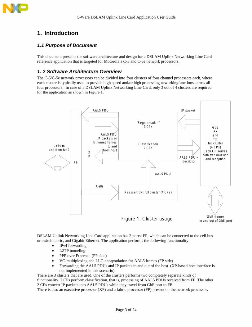
1. 2 Software Architecture OverviewThe C-5/C-5e network processors can be divided into four clusters of four channel processors each, whereeach cluster is typically used to provide high speed and/or high processing neworkingfunctions across allfour processors. In case of a DSLAM Uplink Networking Line Card, only 3 out of 4 clusters are requiredfor the application as shown in Figure 1.
DSLAM Uplink Networking Line Card application has 2 ports: FP, which can be connected to the cell busor switch fabric, and Gigabit Ethernet. The application performs the following functionality:
• IPv4 forwarding• L2TP tunneling• PPP over Ethernet (FP side)• VC-multiplexing and LLC-encapsulation for AAL5 frames (FP side)• Forwarding the AAL5 PDUs and IP packets in and out of the host (XP-based host interface is
not implemented in this scenario)There are 3 clusters that are used. One of the clusters performs two completely separate kinds offunctionality. 2 CPs perform classification, that is, processing of AAL5 PDUs received from FP. The other2 CPs convert IP packets into AAL5 PDUs while they travel from GbE port to FPThere is also an executive processor (XP) and a fabric processor (FP) present on the network processor.
FP
"Segmentation"2 CPs
Reassembly: full cluster (4 CPs)
GbERxandTx:
full cluster(4 CPs)
Each CP servesboth transmission
and reception
Classification2 CPs
AAL5 PDU +decriptor
IP packetAAL5 PDU
Cells
AAL5 PDU
XP
AAL5 PDUIP packets or
Ethernet framesto and
from hostCells to
and from Mt-2
GbE framesin and out of GbE portFigure 1. Cluster usage
C-Ware DSLAM Uplink Line Card Application User Guide
Page 4 of 24
1.3 Data flow overviewThe DSLAM application supports a number of different types of traffic. Traffic flowing from FP to Gigabitis called upstream. Traffic flowing from Gigabit port to FP is called downstream. Traffic flowing to thehost is called host-bound. Traffic flowing from the host is called host-generated.All cells coming in and out of FP belong to a particular Virtual Circuit. Every cell has 4-byte header, whichcontains 24-bit VPI/VCI that determines VC. 4-byte header is not a part of a cell body. When the cellcomes into the FP, cell header is stripped and saved in a descriptor. When the cell goes out of FP,descriptor is added to the cell.Only AAL5 is supported by the DSLAM Uplink Networking Line Card application in this example.
1.3.1 Upstream trafficThe following types of traffic (AAL5 frames) are supported through the DSLAM Uplink Networking LineCard application, processed and passed to the GbE port:• IP over AAL5, both VC-multiplexing and LLC-encapsulation. Forwarded from GbE port as an IP
packet• PPP over Ethernet over AAL5, both VC-multiplexing and LLC-encapsulation. Goes out of GbE port as
L2TP frame, encapsulated within UDP datagram• PPP over AAL5, both VC-multiplexing and LLC-encapsulation. Goes out of GbE port as L2TP frame,
encapsulated within UDP datagramEach VC has a type of traffic assigned to it. For a particular VC, DSLAM application passes only thoseframes that match an exact traffic definition of that VC. Otherwise, the frame is dropped.Upstream traffic is shown on a picture 2.
1.3.2 Downstream trafficThe following types of processing are supported on GbE port:• IP forwarding• L2TP frame tunnelingDSLAM application selects the processing mode based on IP DA, source and destination UDP portDownstream traffic is shown on a picture 3.
1.3.3 Host-bound trafficSome frames received on a FP are forwarded to the host. Among them are:• Host-bound IP over AAL5 frames (IP DA = internal IP addr)• PPP over Ethernet discovery frames• PPP control frames, in case when the session hasn’t been established yet• IP over AAL5 frames, in case when the route has been established but not resolved through ARPHost-bound traffic is shown on a picture 4.
Some Ethernet frames and IP packets received on GbE port are also forwarded to the host. Among themare:• Ethernet ARP frames• Host-bound IP packets• L2TP control packets
1.3.4 Host-generated trafficDSLAM Uplink Networking Line Card application is not concern with the kind of frame the host wants tosend to FP. It just has to be a valid AAL5 frame. Likewise, DSLAM Uplink Networking Line Cardapplication will forward to GbE port any Ethernet frame or IP packet generated by the hostThe host enqueues IP packet and Ethernet frame descrptors directly into the input queue of GbE clusterLikewise, the host enqueues the AAL5 PDU descriptor directly into the input queue of FP.

C-Ware DSLAM Uplink Line Card Application User Guide
Page 5 of 24
FPFP strips 4-byte header from the incoming celLaunches VPI/VCI lookup and obtains VC index andprocessing mode for that VC
Gigabit CP
Reassembly CP builds an entire AAL5 PDU out ofincoming cells. It keeps the reassembly context inDMEM for each AAL5 PDU currently beingreassembled. To attach a new cell to the PDU, CPsends a cell through the SDP recirculation path
Classification CP
Classification CP sends an incoming AAL5 PDUthrough the SDP recirculation pathRxByte verifies LLC header and AAL5 PDU CRC All
launches IP DA lookup IPlaunches PPPoE session lookup PPPoElaunches VC index lookup PPPcalculates the payload checksum PPP and PPPoE
RC obtains:the IP forwarding information (MAC DA) IPthe L2TP forwarding information (MAC DA,IP DA, UDP dest port, L2TP tunnel/session PPP and
PPPoE
Reassembly CP
Gigabit CP (TxByte):Strips LLC header if it present AllAdds Ethernet MAC header AllAdds IP header, UDP header and L2TP header L2TPStrips AAL5 trailer and calculates Ethernet CRC All
RasCellDescriiptorATM cell descriptor
(Btag, VC index, mode)
RasToClassDescriptorAAL5 PDU descriptor
(Btag, VC index, mode)
ClassToGbeDescriptorAAL5 PDU descriptor with
forwarding information(Btag, MAC client, MAC
DA)
Ethernet framecontaining an IP packet
Picture 2. Upstream traffic
ATM cells
C-Ware DSLAM Uplink Line Card Application User Guide
Page 6 of 24
FP
Gigabit CP
Segmentation CP
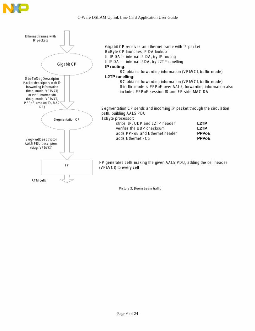
Gigabit CP receives an ethernet frame with IP packetRxByte CP launches IP DA lookupIf IP DA != internal IP DA, try IP routingIf IP DA == internal IPDA, try L2TP tunellingIP routing:
RC obtains forwarding information (VPI/VCI, traffic mode)L2TP tunelling:
RC obtains forwarding information (VPI/VCI, traffic mode)If traffic mode is PPPoE over AAL5, forwarding information alsoincludes PPPoE session ID and FP-side MAC DA
Segmentation CP sends and incoming IP packet through the circulationpath, building AAL5 PDUTxByte processor:
strips IP, UDP and L2TP header L2TPverifies the UDP checksum L2TPadds PPPoE and Ethernet header PPPoEadds Ethernet FCS PPPoE
FP generates cells making the given AAL5 PDU, adding the cell header(VPI/VCI) to every cell
Ethernet frames wiithIP packets
GbeToSegDescriptorPacket descriptors with IP
forwarding information(btad, mode, VPI/VCI)
or PPP information(btag, mode, VPI/VCI,
PPPoE session ID, MACDA)
SegFwdDesctriptorAAL5 PDU descriptors
(btag, VPI/VCI)
Picture 3. Downstream traffic
ATM cells

C-Ware DSLAM Uplink Line Card Application User Guide
Page 7 of 24
FP
Gigabit CP
Classification CP
Reassembly CP
FP strips 4-byte header from the incoming celLaunches VPI/VCI lookup and obtains VC index andprocessing mode for that VC
ATM cell descriptor(Btag, VC index, mode)
AAL5 PDU descriptor(Btag, VC index, mode)
AAL5 PDU descriptors (btag, size) for:PPPoE discovery framesIP packets with IP DA= DSLAM IP addrIP packets with "unresolved" IP addressPPP control frames in case there is no sessionyet
XP
Ethernet frames wiithIP packets
Ethernet frame desriptors (btag, size) for:ARP frames
IP packet descriptors (btag, size)for:IP packets with IP DA= DSLAM IP addrL2TP control packets
Picture 4. Host-bound traffic
ATM cells

C-Ware DSLAM Uplink Line Card Application User Guide
Page 8 of 24
2. Component design
2.1 Executive processor (XP)XP performs the following functions:
• Initialization of BMU, TLU, QMU and CP clusters• Host communication: sending buffers and descriptors between the host and CPs*• Maintaining the L2TP tunnel timers
• - Not implemented by Motorola.
2.1.1 TimersThe timer is used for monitoring activity on L2TP tunnel. TLU contains a table of timers. Timer ID is anindex to this table. The entry of the Timer table contains a 64-bit cycle counter. Every time the DSLAMUplink Networking Line Card application receives an L2TP data packet, it modifies the correspondingentry in a Timer table, recording the current NPU cycle counter. Working in parallel with CP, XPcontinuously walks through every entry in the Timer Table. For every entry, it compares the current NPUcycle counter with the cycle counter recorded in the entry. If the difference exceeds the threshold value(also a part of a Timer entry), a message to the host is generated (Message generating code is host-specificand is not implemented).The purpose of such timer mechanism is to allow host to generate a “Hello” control L2TP packet,according to the rules of RFC 2661. The host sees only L2TP control packets. It never sees L2TP datapackets flowing through the DSLAM Uplink Networking Line Card application; therefore it needs somemechanism to monitor this activity.See the section “GbE cluster. MacRx thread for more details”.
2.2 Fabric Port (FP)Fabric Port performs reception and transmission of the cells to and from the cell bus.On reception, two components participate: Byte processor and Descriptor Build Engine (DBE).Byte processor operates on a cell header. The cell header contains VPI/VCI (24 bits) and other information,including the EoM (End of PDU) bit. If this bit is set, the cell is the last within a PDU.Byte processor launches VPI/VCI lookup and selects a target queue, which corresponds to one of CPs inthe Reassembly cluster. DBE receives the lookup result and builds the cell descriptor. Cell descriptor (seeRasCellDescriptor description in the QMU section) contains the following information:
• The whole 4-byte cell header, including VPI/VCI and EoM bit• VC index (information from TLU)• Processing mode (information from TLU)• Cell buffer handler
2.3 Reassembly clusterReassembly cluster consists of 4 CPs performing the same functionality. Each CP has a dedicated inputqueue. FP selects a queue to put a new cell into in a round-robin fashion, so every CP gets its share oftraffic. Each CP has 2 threads running on a Risc Core – RasIn and RasOut. The SDP forwarding path isconfigured for the recirculation mode.All 4 CPs share a table located in DMEM. The table contains 4096 entries, each of which represents oneVC. The entry contains the reassembly context, information that has to be kept between subsequent cells ofthe same AAL5 PDU.

C-Ware DSLAM Uplink Line Card Application User Guide
Page 9 of 24
2.3.1 InitializationThe DCPmain program, which serves at the entry point for the Reassembly cluster code, is fairly simple. Itinitializes the various CPI services which receive and transmit processing will rely on (kernel, buffer, pdu,table, and queue services), initializes the buffer pool to be used by this CPRC’s receive processing forbuffer allocations, initializes SDP recirculation path. Once initialization completes, the main program callsthe “RasIn” processing which will never return.
2.3.2 CPRC RasIn ThreadThe CPRC “RasIn” thread consists of a large While(1) loop which repeats the following steps endlessly:
• Waits and receives a cell descriptor from the dedicated input queue• Looks in the context table to see if there is a reassembly operation in progress. If the entry for
that VC is empty, than the incoming cell is considered to be the first in the PDU. The newbuffer is allocated for that PDU and its handle is stored in the context table, as well as theoffset within a PDU. If the entry is not empty, the buffer handle and offset is taken from there
• Stores buffer handle, VC index, processing mode (not used in Reassembly cluster), offset andEOM status (last cell/not last cell) in Merge Space and initiates DMA of the cell into therecirculation path. Offset is a number 0, 1,2…, meaning the position of the cell within a PDU.The byte offset can be calculated by multiplying it by 48. Buffer handle is the one of AAL5PDU being reassembled.
It is possible that different CPs work on reassembly of the same PDU. Therefore, access to the context tablein DMEM is protected with a token.
2.3.3 CPRC RasOut ThreadThe CPRC “RasOut” thread consists of a large While (1) loop which repeats the following steps endlessly:
• Waits and receives a PDU handle. The PDU handle corresponds to the cell that just wentthrough the recirculation circle
• CPRC reads the buffer handle, offset, VC index, processing mode and EOM status from theExtract space
• CPRC uses the buffer handle and offset information to set up DMA. Buffer handle is thebuffer handle of an entire AAL5 PDU (don’t be confused with a PDU handle, which is a CPIabstraction for the processing scope).
• CPRC waits until the DMA is complete.• If the EOM status =1, the cell was the last cell of a PDU. Therefore, reassembly of this PDU
is finished. CPRC builds the PDU descriptor and enqueues it into the Classification clusterqueue. AAL5 PDU descriptor contains:• Buffer handle• PDU length• VC index• Processing modeCPRC takes the PDU length from extract space, because it will contain the AAL5 PDU trailer(see below the description of RxByte).
2.3.4 TxByteTxByte microcode is simple. First, it reads VC index, processing mode, offset end EOM status from theMerge Space, sends them “downstream”. Then it forwards downstream the cell content, reading it from itsPayloadIn bus.Because TxByte output FIFO is connected to the RxByte FIFO via the recirculation mechanism, RxBytewill see output stream of TxByte as its own input stream.

C-Ware DSLAM Uplink Line Card Application User Guide
Page 10 of 24
2.3.5 RxByteRxByte receives its input stream from TxByte. First, the input stream contains the cell parameters:• VC index• processing mode• offset• Buffer handle• EOM status.Then, it contains 48 bytes of a cell. RxByte writes parameters into the Extract space. Then it sets L1DONEflag, so the CPRC can get the PDU handle and start processing the cell. Then it forwards 48 bytes of a cellto the DMA engine. At the end RxByte switches the scope. In addition to forwarding to the DMA engine,RxByte stores the last 8 bytes of a cell in Extract Space. For the last cell, these 8 bytes will contain theAAL5 PDU trailer.
2.4 Classification clusterClassification “cluster” is not a real cluster, because it consists of only 2 CPs. Both CPs of theClassification cluster share a single input queue, where the Reassembly CPs send the AAL5 PDUs.
2.4.1 InitializationClassification “cluster” doesn’t have its own exclusive DCPmain() entry point. It shares the entry pointwith 2 CPs of Segmentation cluster, because technically they are located within the same NPU cluster.This combined DCPmain entry point performs different operations for Classification and SegmentationCPs. The common operation is to initialize BMU, QMU and other CPI services.For Classification CP it performs the following functions:• Initializes TLU lookups for VC table, Session table and IP table• Configures the SDP recirculation path. It sets the DSLAM internal FP-side Ethernet MAC address into
the Control space of RxByte• Initializes 2-way queue sharing for a Classification cluster Input queue• Launches 2 Threads: ClassIn and ClassOut
2.4.2 CPRC ClassIn ThreadThe CPRC “ClassIn” thread consists of a large While(1) loop which repeats the following steps endlessly:
• Waits and receives an AAL5 PDU descriptor from the shared Input queue• Stores VC index, processing mode, and PDU length in Merge Space and initiates DMA of the
PDU into the recirculation path.
2.4.3 CPRC ClassOut ThreadThe CPRC “ClassOut” thread performs most of the decision making about the AAL5 PDU.The ClassOut thread consists of a large While(1) loop, which is passed once for every received PDU.First, ClassOut thread blocks waiting on a PDU handle. When the PDU handle is obtained, CPRC readsfrom the extract space: processing mode, PDU length, BytesToSkip and PDU status. Further processingdepends on a processing mode. BytesToSkip is parameter of PDU calculated by the RxByte. It means howmany bytes have to be skipped before the actual payload. BytesToSkip depends on processing mode only.For IP over AAL5 PDU Header length may include only LLC-header length. For PPPoE L2TP, Headerlength may include LLC-header length, the size of Ethernet and PPPoE headersDepending on a processing mode, ClassOut thread selects on of the 3 possible major paths: IP routing,L2TP tunneling/PPP or L2TP tunneling/PPPoE
C-Ware DSLAM Uplink Line Card Application User Guide
Page 11 of 24
2.4.3.1 IP routingThe CPRC obtains results of the IP DA Lookup launched by the RxByte. There could be 4 possible resultsof the lookup:• Forwarding information present and valid: MAC DA, and the output port is GbE• IP DA = DSLAM Internal addr• Forwarding information not present or invalid• Forwarding information is incomplete. MAC DA not present, but it is known that the route is valid and
the output port is GbEIn the first case, PDU will be forwarded to GbE clusterIn the third case, PDU will be discardedIn the second and forth case, PDU will be forwarded to the host
2.4.3.2 L2TP tunneling/PPPThe CPRC obtains results of the VC index lookup launched by the RxByte. There could be 2 possibleresults of the lookup:• Forwarding information present: MAC DA, IP DA, UDP dest port, L2TP tunnel and session ID• If L2TP session ID =0, L2TP session has not been established yet, because 0 is reserved numberIn the first case, PDU will be forwarded to GbE clusterIn the second case, CPRC looks onto the 2-byte protocol ID of the PPP frame. RxByte extracts and putsthis ID into the extract space. If the protocol is the control protocol (bit 15 of the protocol ID is not 0),PDU will be forwarded to the host, otherwise it is discarded.
2.4.3.3 L2TP tunneling/PPPoEThe CPRC obtains results of the PPPoE session ID lookup launched by the RxByte. There could be 2possible results of the lookup:• Forwarding information present: MAC DA, IP DA, UDP dest port, L2TP tunnel and session ID• Forwarding information not present: lookup was not successful.In the first case, PDU will be forwarded to GbE clusterIn the second case, CPRC looks onto the 2-byte protocol ID of the PPP frame. RxByte extracts and putsthis ID into the extract space. If the protocol is the control protocol (bit 15 of the protocol ID is not 0),PDU will be forwarded to the host, otherwise it is discarded.
2.4.3.4 Special casesIf the PDU is PPPoE discovery frame, RxByte determines that its destination is host, and sets the status inthe Extract space accordingly. In this case no PPPoE session lookup is launched, and therefore no result isobtained.Also RxByte can determine that PDU is not valid. See below the detailed description of the RxByte. In thiscase the status in the Extract space will show that the PDU should be discarded.
2.4.3.5 CRC verificationAfter CPRC has classified the PDU and determined its destination, it waits for the DMA to end. At the endof the PDU, RxByte puts into the extract space the CRC verification status. CPRC reads the status and ifthe CRC verification had failed, it discards the PDU instead of sending it to the GbE cluster or host.
2.4.3.6 Building a descriptor and forwarding PDUIf CPRC had determined that the destination is host, it builds the following descriptor:
• Buffer handle• Payload type: AAL5• AAL5 PDU size• VC index

C-Ware DSLAM Uplink Line Card Application User Guide
Page 12 of 24
Then it forwards it to the XP-owned queue. XP is the ultimate middlemen for CP-host communicationIf CPRC had determined that the destination is GbE, it builds the following descriptor:
• Buffer handle• MAC client: macClientTxIp or macClientTxL2TP• BytesToSkip• Payload length. Includes only payload bytes that will be sent out by GbE cluster, without any
AAL5-specific or PPPoE specific headers, trailers or pads• MAC DA• IP DA (L2TP only)• UDP dest Port (L2TP only)• L2TP tunnel ID• L2TP session ID• Payload checksum. RxByte calculates it and puts into the extract space. Used only with L2TP
Then it forwards it to the GbE-owned queue.
If RxByte or CPRC have determined that PDU should be discarded, the buffer handle is freed and nodescriptor is forwarded.
2.4.4 TxByteTxByte microcode is simple. First, it reads VC index, processing mode, and payload length from the MergeSpace, sends them “downstream”. Then it forwards downstream the PDU content, reading it from itsPayloadIn bus.Because TxByte output FIFO is connected to the RxByte FIFO via the recirculation mechanism, RxBytewill see output stream of TxByte as its own input stream.
2.4.5 RxByteRxByte microcode first reads the parameters: VC index, processing mode and payload length from theinput stream. It saves the in the extract space. Then the processing depends on a processing mode.Processing mode is actually a bit field, specifying various characteristics of a VC:• Forwarding mode: IP routing, PPP – L2TP or PPPoE – L2TP• LLC-encapsulation or VC-multiplexing• For PPPoE, whether Ethernet FCS is present or not
bits 15-8: currently unusedbit 7: How to forward out of GbE:
0 = bridge (Protocol over AAL5 = 0) or route (Protocol over AAL5 = 1, 2, 3, 4)1 = L2TP (Protocol over AAL5 = 1 or 4)
bits 6-4: Protocol over AAL5: Enet, PPPoE, IPoE, IP or PPP0 = Ethernet1 = PPP over Ethernet2 = IP over Ethernet3 = IP4 = PPP
bit 3: LLC or VC mux0 = VC mux (No LLC header)1 = LLC/SNAP header
bit 2: Whether the Enet over AAL5 frame contains FCS0 = no FCS1 = FCS present
C-Ware DSLAM Uplink Line Card Application User Guide
Page 13 of 24
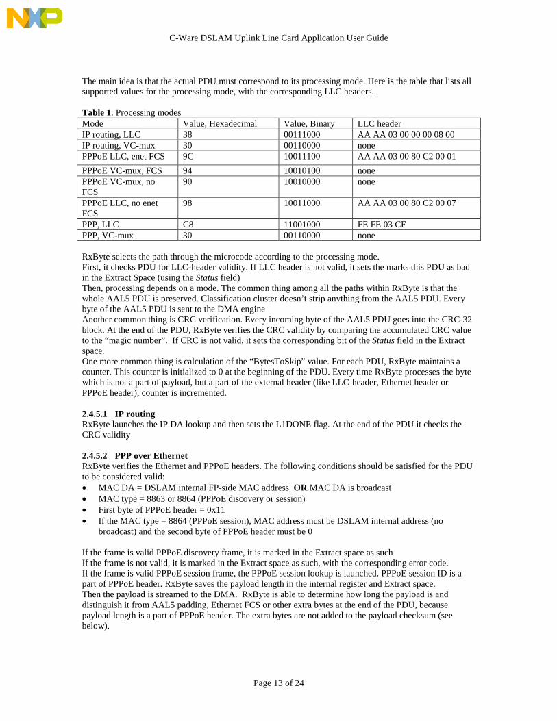
The main idea is that the actual PDU must correspond to its processing mode. Here is the table that lists allsupported values for the processing mode, with the corresponding LLC headers.
Table 1. Processing modesMode Value, Hexadecimal Value, Binary LLC headerIP routing, LLC 38 00111000 AA AA 03 00 00 00 08 00IP routing, VC-mux 30 00110000 nonePPPoE LLC, enet FCS 9C 10011100 AA AA 03 00 80 C2 00 01
PPPoE VC-mux, FCS 94 10010100 nonePPPoE VC-mux, noFCS
90 10010000 none
PPPoE LLC, no enetFCS
98 10011000 AA AA 03 00 80 C2 00 07
PPP, LLC C8 11001000 FE FE 03 CFPPP, VC-mux 30 00110000 none
RxByte selects the path through the microcode according to the processing mode.First, it checks PDU for LLC-header validity. If LLC header is not valid, it sets the marks this PDU as badin the Extract Space (using the Status field)Then, processing depends on a mode. The common thing among all the paths within RxByte is that thewhole AAL5 PDU is preserved. Classification cluster doesn’t strip anything from the AAL5 PDU. Everybyte of the AAL5 PDU is sent to the DMA engineAnother common thing is CRC verification. Every incoming byte of the AAL5 PDU goes into the CRC-32block. At the end of the PDU, RxByte verifies the CRC validity by comparing the accumulated CRC valueto the “magic number”. If CRC is not valid, it sets the corresponding bit of the Status field in the Extractspace.One more common thing is calculation of the “BytesToSkip” value. For each PDU, RxByte maintains acounter. This counter is initialized to 0 at the beginning of the PDU. Every time RxByte processes the bytewhich is not a part of payload, but a part of the external header (like LLC-header, Ethernet header orPPPoE header), counter is incremented.
2.4.5.1 IP routingRxByte launches the IP DA lookup and then sets the L1DONE flag. At the end of the PDU it checks theCRC validity
2.4.5.2 PPP over EthernetRxByte verifies the Ethernet and PPPoE headers. The following conditions should be satisfied for the PDUto be considered valid:• MAC DA = DSLAM internal FP-side MAC address OR MAC DA is broadcast• MAC type = 8863 or 8864 (PPPoE discovery or session)• First byte of PPPoE header = 0x11• If the MAC type = 8864 (PPPoE session), MAC address must be DSLAM internal address (no
broadcast) and the second byte of PPPoE header must be 0
If the frame is valid PPPoE discovery frame, it is marked in the Extract space as suchIf the frame is not valid, it is marked in the Extract space as such, with the corresponding error code.If the frame is valid PPPoE session frame, the PPPoE session lookup is launched. PPPoE session ID is apart of PPPoE header. RxByte saves the payload length in the internal register and Extract space.Then the payload is streamed to the DMA. RxByte is able to determine how long the payload is anddistinguish it from AAL5 padding, Ethernet FCS or other extra bytes at the end of the PDU, becausepayload length is a part of PPPoE header. The extra bytes are not added to the payload checksum (seebelow).

C-Ware DSLAM Uplink Line Card Application User Guide
Page 14 of 24
2.4.5.3 PPPRxByte launches VC-index lookup. In case of PPP, payload length is equal to AAL5 payload length.RxByte knows the AAL5 payload length, because the TxByte as a part of the “pre-PDU” parameters sentthe AAL5 payload length to it.
2.4.5.4 Common for PPP and PPP over Ethernet
RxByte saves the PPP protocol ID in the Extract space. Then it sets the L1DONE flag.RxByte calculates the Payload checksum. It includes all the bytes, which are part of PPP frame, includingthe protocol ID, but NOT including PPPoE and other external headers. Payload checksum is 16-bitchecksum. It is needed to transmit the UDP checksum with L2TP packet out of the GbE port.
2.5 GbE clusterGbe cluster here serves both transmit and receive sides of GbE port.
2.5.1 InitializationThe DCPmain program, which serves at the entry point for the Reassembly cluster code, performs thefollowing functions:• Initializes CPI services• Configures SDP. GbE internal MAC address is set in the control spaces of both RxByte and TxByte• Initializes IP DA TLU lookup• Launches 2 threads: MacRx to serve reception and MacTx to serve transmission
2.5.2 CPRC MacRx threadThe CPRC “MacRx” thread consists of a large While(1) loop which repeats the following steps endlessly:• Waits and receives the PDU handle from the RxByte• Checks the type (forwarding path) of the incoming PDU. It can be IP packet or ARP request.
Everything else is considered to be invalid and discarded. If the frame is ARP request, it is forwardedto the host. If it is IP packet, CPRC checks if the IP DA = DSLAM internal IP address. IP DA is takenfrom the Extract space. If IP DA is not the internal address of the DSLAM, then CPRC assumes thatthe packet is going to be routed. Otherwise the packet is either L2TP or host-bound.
2.5.2.1 IP routingCPRC obtains the IP DA lookup result. If the route (forwarding information) is present, CPRC buildsthe IP packet descriptor and forwards it to the Segmentation cluster. The IP packet descriptor contains:• Buffer handle• Packet size• VPI/VCI – from TLU IP routing table entry• Processing mode - from TLU IP routing table entryProcessing mode is the same bit field format as the one used in the classification cluster. It mustcontain bits specifying the IP routing as a forwarding type. It may define LLC-encapsulation or VC-multiplexing.There are some cases when MacRx will generate ICMP message with corresponding descriptor andsend it to the GbE Tx side. These are:• Route is not present. In this case the ICMP message “Destination unreachable” is generated.• Route is located on GbE side. In this case the ICMP message “Redirect” is generated. Both the
ICMP message and the original IP packet are forwarded out of GbE port• TTL expired. TTL is a part of IP packet header and is located in Extract Space. In this case the IP
packet is not forwarded and the “Time Exceeded” ICMP message is generated.

C-Ware DSLAM Uplink Line Card Application User Guide
Page 15 of 24
2.5.2.2 L2TP tunnelingIf IP DA is the internal address of the DSLAM, CPRC reads the first 64 bytes of the packet from theSDRAM to DMEM. It then checks the following condition to determine if the processing type isindeed L2TP tunneling:• The protocol must be UDP - 17. Otherwise the packet is forwarded to the host.• UDP dest port must be the UDP port assigned for the L2TP – 1701. Otherwise the packet is
forwarded to the host• UDP datagram length should match the IP packet length. Otherwise the packet is discarded• L2TP packet type must be data, not control. Otherwise the packet is forwarded to the host• L2TP version must be 2. Otherwise the packet is discarded.• L2TP packet length should match the IP packet length. Otherwise the packet is discarded.• L2TP tunnel ID must be not 0. Otherwise the packet is forwarded to the host• L2TP session ID must be not 0. Otherwise the packet is forwarded to the hostThen, if the packet is valid L2TP data packet, MacRx thread launches the L2TP session lookup.If the lookup returns L2TP forwarding information successfully:• L2TP forwarding information is used to build a descriptor for the Segmentation cluster• L2TP forwarding information contains Timer ID. Each L2TP tunnel has a timer associated with it.
The timer is used for monitoring activity on L2TP tunnel. TLU contains a table of timers. TimerID is an index to this table. The entry of the Timer table contains a 64-bit cycle counter. Everytime the DSLAM application receives an L2TP data packet, it modifies the corresponding entry ina Timer table, recording the current NPU cycle counter. Working in parallel with CP, XPcontinuously walks through every entry in the Timer Table. For every entry, it compares thecurrent NPU cycle counter with the cycle counter recorded in the entry. If the difference exceedsthe threshold value (also a part of a Timer entry), a message to the host is generated (Messagegenerating code is host-specific and is not implemented).The purpose of such timer mechanism is to allow host to generate a “Hello” control L2TP packet,according to the rules of RFC 2661. The host sees only L2TP control packets. It never sees L2TPdata packets flowing through the DSLAM application, therefore it needs some mechanism tomonitor this activitySo, the MacRx thread sends a TLU request “Modify Entry” for every received data L2TP packet,using the Timer ID as an index and recording the current NPU cycle counter.
The L2TP forwarding information (FP direction) contains the following entries:• VPI/VCI• Processing mode (PPP or PPPoE, LLC-encapsulation or VC-multiplexing and so on)• PPPoE session (PPP over Ethernet mode only)• FP-side MAC DA (PPP over Ethernet mode only)
2.5.3 CPRC MacTx threadCPRC MacTx thread initiates forwarding IP packets, L2TP packets or Ethernet frames to the GbE portThe CPRC “MacTx” thread consists of a large While(1) loop which repeats the following steps endlessly:• Waits and dequeues a descriptor from the shared GbE cluster queue. A single input queue is shared
between 4 CPs of the GbE cluster. A descriptor contains the following information:• Buffer handle• MAC client ID (what kind of processing is needed): Ethernet, IP or L2TP• Bytes to skip before payload. The buffer may begin with bytes that are not part of payload and
should not be transmitted• Payload length. The buffer may contain extra bytes after the payload, which should not be
transmitted as well.• IP forwarding information: MAC DA• L2TP forwarding information: UDP destination port, L2TP tunnel ID and session ID, payload
checksum

C-Ware DSLAM Uplink Line Card Application User Guide
Page 16 of 24
The descriptor may come from 3 sources:• Classification cluster. This is the main upstream data flow. It can define IP packet or L2TP packet• Host. Host may want to transmit IP packets and Ethernet frames out of GbE port. If the host wants
to transmit L2TP packet, it actually builds the whole IP packet or Ethernet frame, since L2TPpacket is always encapsulated within IP packet
• Gbe MacRx thread. These are ICMP packets and redirected IP packets
• Prepares the Merge Space for TxByte SDP. Merge space will contain all the needed information fromthe descriptor, including the MAC client ID. For L2TP packets, Merge Space will contain IP SA andDA, UDP source and destination ports, L2TP tunnel ID and session ID, IP packet length, UDPdatagram length and L2TP packet length
• Launches the DMA of the buffer from SDRAM to the TxByte SDP
2.5.4 TxByte SDPTxByte SDP builds and transmits IP packets, Ethernet frames and L2TP packets out of GbE port. TxByteselects the processing path according to the MAC client ID value, which it takes from its Merge Space.
2.5.4.1 MAC client EthernetIn this case the input stream of TxByte contains the whole Ethernet frame without FCS. TxByte sends theinput bytes downstream, adding the FCS at the end. FCS is CRC-32, calculated using the CRC block
2.5.4.2 MAC client IPIn this case the input stream of TxByte contains the IP packet. TxByte performs the following actions:• Adds the Ethernet header, containing MAC SA, MAC DA and protocol (IP). MAC SA and MAC DA
are taken from the Merge Space. Sends the Ethernet header downstream• Decrements the TTL value of IP packet header, changes the IP checksum accordingly. Sends the
modified IP packet bytes downstream• Adds the Ethernet FCS
2.5.4.3 MAC client L2TPIn this case the input stream of TxByte contains the AAL5 PDU, which was built by the Reassemblycluster. TxByte performs the following actions:• Skips the header bytes. The number of bytes to skip is determined by the parameter “BytesToSkip”,
which is taken from the Merge Space• Adds the Ethernet header, containing MAC SA, MAC DA and protocol (IP). MAC SA and MAC DA
are taken from the Merge Space. Sends the Ethernet header downstream• Builds and adds the IP header. IP SA, IP DA, IP packet length are taken from the Merge Space.• Builds and adds the UDP header. UDP checksum is calculated using the Payload checksum value
taken from the Merge Space. UDP source port, UDP destination port, UDP datagram length are alsotaken from the Merge Space
• Builds and adds the L2TP header. L2TP tunnel ID and session ID, L2TP packet lengths are taken fromthe Merge Space.
• Sends the payload bytes downstream• Adds the Ethernet FCS
2.6 Segmentation clusterSegmentation cluster doesn’t actually build the segments, or ATM cells. It merely builds the AAL5 PDU.Segmentaion cluster is not a real cluster either. It contains just 2 CPs, which are technically located withinthe same cluster as Classification CPs
2.6.1 InitalizationSegmentaion “cluster” doesn’t have its own exclusive DCPmain() entry point. It shares the entry point with2 CPs of Classification cluster, because technically they are located within the same NPU cluster.

C-Ware DSLAM Uplink Line Card Application User Guide
Page 17 of 24
This combined DCPmain entry point performs different operations for Classification and SegmentationCPs. The common operation is to initialize BMU, QMU and other CPI services.For Segmentation CP it performs the following functions:• Configures the SDP recirculation path. It sets the DSLAM internal FP-side Ethernet MAC address
into the Control space of TxByte• Initializes 2-way queue sharing for a Segmentation cluster Input queue• Launches 2 Threads: SegIn and SegOut
2.6.2 CPRC SegIn threadThe CPRC “SegIn” thread consists of a large While(1) loop which repeats the following steps endlessly:• Waits and receives a Segmentation descriptor from the shared Input queue• Stores VPI/VCI, processing mode, payload length, MAC DA and PPPoE session ID (PPPoE L2TP
only) in Merge Space and initiates DMA of the PDU into the recirculation path.
2.6.3 CPRC SegOut ThreadThe SegOut thread consists of a large While(1) loop, which is passed once for every received PDU. SegOutthread performs the following actions:• Waits and obtains a PDU from the RxByte• Waits for payload to be fully transferred into the SDRAM• For L2TP packets, checks the UDP checksum verification result. RxByte performs this verification and
puts its result into the Extract Space. If UDP checksum is not valid, PDU is discarded• Selects the input queue for FP. Each CP has two FP queues assigned to it. Each CP “flip-flops”
between them for every PDU: the first PDU goes into the first queue, the next one goes into thesecond, and then the next goes into the first one, and so on. Overall, FP Tx Engine has 4 queuesfeeding it, 2 queues from each CP
• Builds the descriptor for FP and enqueues it into the selected queue. Descriptor for FP has thefollowing fields:• VPI/VCI• PDU length
2.6.4 TxByte SDPTxByte SDP builds an entire AAL5 PDU (without 4 final CRC bytes) and forwards it further into therecirculation path. The way to build the AAL5 PDU depends on a processing mode. First, the TxByte SDPreads the processing mode, VPI/VCI and PDU length from Merge Space. Then it forwards the processingmode and VPI/VCI further downstream, so RxByte can see them just before the actual PDUIf the mode specifies LLC-encapsulation, TxByte generates the LLC header according to the forwardingmode. See the table 1 above.Then, if the mode specifies IP routing, TxByte simply forwards payload bytes downstreamIf the mode specifies PPP over AAL5 or PPPoE over AAL5, TxByte does the following:• Skips IP header, UDP header and L2TP header. Saves the UDP checksum in the internal register.• Starts calculating the UDP checksum. UDP checksum is the combination of payload checksum, L2TP
and UDP header checksum and checksum of several fields within IP header (so called“pseudoheader”).
Now, if the mode specifies PPP over Ethernet, TxByte builds and sends downstream the Ethernet headerand PPPoE header. MAC SA, MAC DA, PPPoE session ID are taken from the Merge Space. Otherwise, ifthe mode specifies PPP over AAL5, TxByte goes right to the forwarding the payload bytes• Forwards payload bytes downstream, adding the bytes to the UDP checksum on a way• For PPPoE only: if the resulting Ethernet frame length is less than 64 bytes (60 bytes in case Ethernet
FCS should be added), TxByte sends downstream the corresponding number of padding zeros• For PPPoE only: if the processing mode specifies that the Ethernet FCS header should be added,
TxByte reads the 4-byte value from the CRC block and sends downstream. For PPPoE, every bytebelonging to the Ethernet frame (including Ethernet header, PPPoE header and payload) goes throughthe CRC-32 block
C-Ware DSLAM Uplink Line Card Application User Guide
Page 18 of 24
Now, for all the processing modes, the AAL5 PDU padding is added, and then the AAL5 PDU trailer.The only thing that is not added here is AAL5 PDU CRC. The RxByte does it.Finally, if the processing mode is PPP or PPP over AAL5, TxByte verifies the UDP checksum. It comparesthe calculated value of UDP checksum with the stored value, which was taken from the actual UDP header.If they match, TxByte sends dowstream the value 1. Otherwise, it sends the value 0.
2.6.5 RxByte SDPRxByte SDP receives PDU from the TxByte, because they are connected via the recirculation pathFirst, RxByte SDP receives VPI/VCI and processing mode, and stores them in Extract space.Then, it receives the AAL5 PDU and sends it upstream, to the DMA Engine. Every byte is also sent to theCRC-32 block.Upon reaching the end of stream, RxByte reads the CRC value from the CRC-32 block and sends itupstream.Finally, if the processing mode is PPP or PPPoE, it writes the UDP checksum verification result (0 or 1)into the Extract Space.
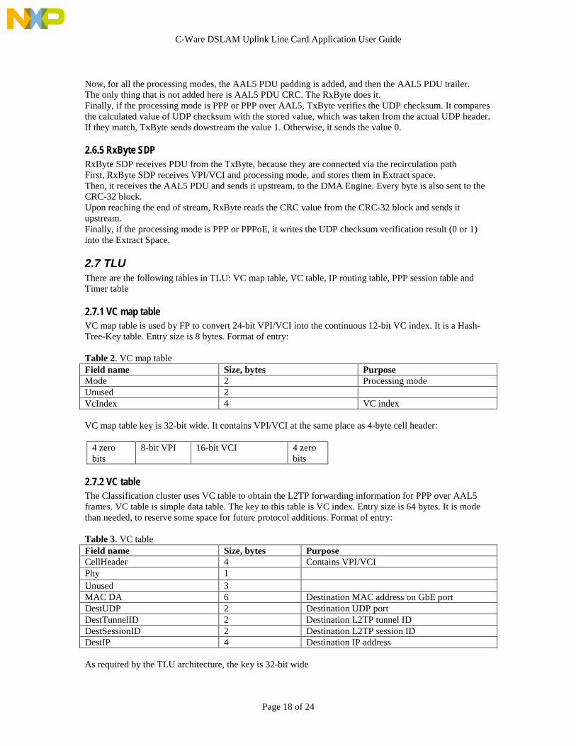
2.7 TLUThere are the following tables in TLU: VC map table, VC table, IP routing table, PPP session table andTimer table
2.7.1 VC map tableVC map table is used by FP to convert 24-bit VPI/VCI into the continuous 12-bit VC index. It is a Hash-Tree-Key table. Entry size is 8 bytes. Format of entry:
Table 2. VC map tableField name Size, bytes PurposeMode 2 Processing modeUnused 2VcIndex 4 VC index
VC map table key is 32-bit wide. It contains VPI/VCI at the same place as 4-byte cell header:
4 zerobits
8-bit VPI 16-bit VCI 4 zerobits
2.7.2 VC tableThe Classification cluster uses VC table to obtain the L2TP forwarding information for PPP over AAL5frames. VC table is simple data table. The key to this table is VC index. Entry size is 64 bytes. It is modethan needed, to reserve some space for future protocol additions. Format of entry:
Table 3. VC tableField name Size, bytes PurposeCellHeader 4 Contains VPI/VCIPhy 1Unused 3MAC DA 6 Destination MAC address on GbE portDestUDP 2 Destination UDP portDestTunnelID 2 Destination L2TP tunnel IDDestSessionID 2 Destination L2TP session IDDestIP 4 Destination IP address
As required by the TLU architecture, the key is 32-bit wide

C-Ware DSLAM Uplink Line Card Application User Guide
Page 19 of 24
2.7.3 IP route tableThe IP route table is used throughout the DSLAM application to obtain the IP route in case IP routing isperformed. On C5 implementation, IP route table is VP Trie-Index-Data table. On C5e/C3eimplementation, IP route table is a PFX table. The entry size is 16 bytes. Format of entry:
Table 4. IP route tableField name Size, bytes Purposemask 1 IP subnet maskbitFields 1 Bitfield:
Bit 7: 0 - egress port FP1 - egress port GbEBit 0: phy channel (used only ifbit 7 == 0)Bit 1: incomplete path - nodefined mac DA yetBit 2: 1 - destination host
mode 2 Processing modecellHeader 4 VPI/VCI is a part of itMAC DA 6 Destination Ethernet MAC
addressPPoESessionID 2 PPPoE session ID, used only if
egress port is FP
The key is 32-bit IP address
2.7.4 PPP session tableThe PPP session table contains forwarding information for two different sets of session Ids. One set is theset of PPP over Ethernet session Ids, and the Classification cluster launches the PPPoE session ID lookups.Another set is the set of L2TP session Ids, and the GbE cluster launches theL2TP session ID lookups.PPP session table is a simple data table. The session ID itself is 12-bit value. The key to the PPP sessiontable is 32-bit wide. Bit 14 is used to distinguish between one set or another. For example, PPPoE sessionIds 1, 2… are converted to keys 0x00000001, 0x00000002, but the L2TP session Ids 1, 2,… are convertedto keys 0x00004001, 0x00004002, … etc.
The entry size is 32 bytes. Format of entry depends on a set of keys. For PPPoE set of keys, format is thefollowing:
Table 5. PPP session table, PPPoE sessionsField name Size, bytes PurposeMode 2 Processing modeBitFields 1 Bit 7: 0 - egress port ATM
1 - egress port GbEBit 0: phy channel (used only ifbit 7 == 0)
Unused 5MAC DA 6 Destination MAC address on
GbE portdestUDP 2 Destination UDP portdestTunnelID 2 Destination L2TP tunnel IDdestSessionID 2 Destination L2TP session IDdestIP 4 Destination IP address

C-Ware DSLAM Uplink Line Card Application User Guide
Page 20 of 24
For L2TP set of keys, format is the following:
Table 6. PPP session table, L2TP sessionsField name Size, bytes PurposeMode 2 Processing modeBitFields 1 Bit 7: 0 - egress port ATM
1 - egress port GbEBit 0: phy channel (used only ifbit 7 == 0)
MAC DA 6 FP-side Ethernet MAC DA (PPPover Ethernet only)
PPPoESesssionID 2 PPP over Ethernet session IDCellHeader 4 VPI/VCI is a part of itTimer ID 2 Timer ID corresponding to the
L2TP session, which is lookuplaunched upon; there is one timerper tunnel, so for all sessionswithin the same tunnel, timerIDvalue is the same
2.7.5 Timer TableTimer table is used to monitor activity on a L2TP tunnel. Each L2TP tunnel has a corresponding entry inthis table. The table is accessed from 2 places within NPU. First, the GbE cluster writes the current cyclecounter into the entry every time the L2TP data packet has been received on that tunnel. Second, XPperiodically checks every entry in the table, in order to detect tunnels where no activity happened for morethan a certain period of time.Timer table is a simple data table. The entry size is 32 bytes. The key is TimerID and it is a 32-bit wideindex into this table.Format of entry:Table 7. Timer tableField name Size, bytes PurposeinitialCount 8 Value written by the GbE CP
every time a new packet isreceived
timeToLive 8 Maximum inactivity period. IfXP detects that the differencebetween the initialCount and thecurrent cycle counter is more thantimeToLive, message to the hostshould be generated.
timerType 2 Value 0 means that the entry isnot in useValue 1 means that the timer is inuse an linked to the L2TP tunnel
tunnelId 2 An associated tunnel ID

C-Ware DSLAM Uplink Line Card Application User Guide
Page 21 of 24
2.8 QMUQMU Descriptor size is 32 bytes. Descriptor formats:
RasCellDescriptor: sent from FP to the Reassembly cluster
Table 8. RasCellDesctiptorType Name Size, bytes PurposeBsBufHandle BufHandle 4 Buffer handle for a cellInt32u CellHeader 4 The ATM header of a
cellInt16u Mode 2 Processing mode
Int8u Phy 1 Phy address on a FPInt8u Unused 1Int32u VcIndex 4 VC indexInt32u Unused 16
RasToClassDesctiptor: sent from Reassembly cluster to Classification cluster:
Table 9. RasToClassDescriptorType Name Size, bytes PurposeBsBufHandle BufHandle 4 Buffer handle for an
AAL5 PDUInt16u Mode 2 Processing modeInt32u VcIndex 2 VC indexInt16u pduLength 2 Length of AAL5 PDU
without trailer andpadding. Taken from theAAL5 PDU trailer
Int16u bufLength 2 Length of the wholebuffer, including thepadding and trailer
Int8u unused 20
ClassToGbeDescriptor. This descriptor is sent to the GbE cluster from 3 different sources: Classificationcluster, GbE cluster itself (ICMP packets) and host.
Table 10. ClassToGbeDescriptorType Name Size, bytes PurposeBsBufHandle BufHandle 4 Buffer handle for an
AAL5 PDUInt8u macClient 1 Defines the processing
path through the TxByteInt8u BytesToSkip 1 A number of bytes in the
buffer before thepayload starts
Int16u PayloadLength 2 Payload lengthInt16u + Int32u macDA 6 Destination MAC
addressInt16u Vid 2 Reserved; must be
0xFFFFInt16u TunnelID 2 L2TP tunnel ID

C-Ware DSLAM Uplink Line Card Application User Guide
Page 22 of 24
Int16u SessionID 2 L2TP session ID
Int32u destIP 4 Destination IP addressInt16u DestUDP 2 Destination UDP portInt16u payloadChecksum 2 Payload checksum
GbeToSegDescriptor: This descriptor is sent from the Gigabit cluster to the Segmentation cluster
Table 11. GbeToSegDescriptorType Name Size, bytes PurposeBufHandle BufHandle 4 Buffer handle for the IP
packetInt8u PayloadType 1 Constant value
PAYLOAD_TYPE_IPInt8u UnusedInt16u payloadLength 2 Length of payload
within the bufferFor IP packets – lengthof the whole IP packetFor L2TP packets –length of the L2TPpayload
Int16u Mode 2 Processing mode
Int32u CellHeader 4 Contains VPI/VCIInt32u + Int16u MAC DA 6 FP-side Ethernet MAC
DA (used with PPPoE)Int16u PPPoESessionID 2 PPPoE session IDInt8u Phy 1 Phy channel on FPInt8u Unused 11
SegFwdDescriptor: This descriptor is sent from the Segmentation cluster to the FP:
Table 12. SegFwdDescriptorType Name Size, bytes PurposeBsBufHandle BufHandle 4 Buffer handle for the
AAL5 PDUInt16u Length 2 AAL5 PDU length
(The whole buffer)Int8u Phy 1 Phy channel on a FPInt8u unused 1Int32u CellHeader 4 Contains VPI/VCIInt32u Reserved 20
HostDescriptor: This descriptor is sent to the host. Format of the descriptor depends on the type of packetor frame, which is being sent. The host uses payloadType value to determine the type

C-Ware DSLAM Uplink Line Card Application User Guide
Page 23 of 24
HostDescriptor for AAL5 PDU (sent by the Classification cluster):
Table 13. HostDescriptor, PAYLOAD_TYPE_AAL5Type Name Size, bytes PurposeBsBufHandle bufHandle 4 Buffer handle for the
PDUInt8u payloadType 1 For this descriptor:
PAYLOAD_TYPE_AAL5
Int8u Unused 1Int16u payloadSize 2 Size of the PDUInt16u vcIndex 2 Index of VC where the
PDU came fromInt8u unused 22
HostDescriptor for IP packet (sent by the GbE cluster):
Table 14. HostDescriptor, PAYLOAD_TYPE_IPType Name Size, bytes PurposeBsBufHandle bufHandle 4 Buffer handle for the
packetInt8u payloadType 1 For this descriptor:
PAYLOAD_TYPE_IPInt8u Unused 1Int16u payloadSize 2 Size of the packetInt8u[6] MAC SA 6 Ethernet MAC SA of
the IP packetInt8u unused 22
HostDescriptor for ARP frame (sent by the GbE cluster):
Table 15. HostDescriptor, PAYLOAD_TYPE_ARPType Name Size, bytes PurposeBsBufHandle BufHandle 4 Buffer handle for the
frame (contains thewhole Ethernet frame)
Int8u payloadType 1 For this descriptor:PAYLOAD_TYPE_ARP
Int8u Unused 1Int16u payloadSize 2 Size of the frameInt8u[6] MAC SA 6 Ethernet MAC SA of
the frameInt8u arpType 1 ARP_BROADCAST or
ARP_UNICASTInt8u unused 21

C-Ware DSLAM Uplink Line Card Application User Guide
Page 24 of 24
3. List of RFC
• RFC 2661. Layer Two Tunneling Protocol "L2TP"• RFC 2684 Multiprotocol Encapsulation over ATM Adaptation Layer 5• RFC 2364 PPP over AAL5• RFC 2516 A Method for Transmitting PPP Over Ethernet (PPPoE)• RFC 768 User Datagram Protocol (UDP)