
C OMPONENT & D EPLOYMENT D IAGRAMS Hoang Huu Hanh, Hue University hanh-at-hueuni.edu.vn.
35
COMPONENT & DEPLOYMENT DIAGRAMS Hoang Huu Hanh, Hue University hanh-at-hueuni.edu.vn
-
date post
19-Dec-2015 -
Category
Documents
-
view
219 -
download
3
Transcript of C OMPONENT & D EPLOYMENT D IAGRAMS Hoang Huu Hanh, Hue University hanh-at-hueuni.edu.vn.
COMPONENT & DEPLOYMENT DIAGRAMSHoang Huu Hanh, Hue Universityhanh-at-hueuni.edu.vn
AGENDAIntroduction about componentsComponents and component
diagramsCase studyElements of the componentComponent view: black-box view
and white-box viewDeployment diagrams
INTRODUCTION UML component diagrams describe software
components and their dependencies to each others◦ A component is an autonomous unit within a system◦ The components can be used to define software systems of
arbitrary size and complexity◦ UML component diagrams enable to model the high-level
software components, and the interfaces to those components
◦ Important for component-based development (CBD)◦ Component and subsystems can be flexibly REUSED and
REPLACED◦ A dependency exists between two elements if changes to the
definition of one element may cause changes to the other◦ Component Diagrams are often referred to as “wiring
diagrams”◦ The wiring of components can be represented on diagrams
by means of components and dependencies between them
INTRODUCTIONAn UML diagram classification:Static
◦ Use case diagram, Class diagramDynamic
◦ State diagram, Activity diagram, Sequence diagram, Collaboration diagram
Implementation◦ Component diagram, Deployment diagram
UML components diagrams are Implementation diagrams:
describe the different elements required for implementing a system
INTRODUCTIONAnother classification:Behavior diagrams
◦ A type of diagram that depicts behavior of a systemThis includes activity, state machine, and use case diagrams, interaction diagrams
Interaction diagrams◦ A subset of behavior diagrams which emphasize
object interactions. This includes collaboration, activity, sequence diagrams
Structure diagrams◦ A type of diagram that depicts the elements of a
specification that are irrespective of time. This includes class, composite structure, component, deployment
UML components diagrams are structure diagrams
COMPONENT in UML 2.0Modular unit with well-defined
interfaces that is replaceable within its environment
Autonomous unit within a system ◦Has one or more provided and
required interfaces◦Its internals are hidden and
inaccessible◦A component is encapsulated◦Its dependencies are designed such
that it can be treated as independently as possible
CASE STUDY Development of an application collecting students’
opinions about courses A student can
◦ Read◦ Insert◦ Update◦ Make data permanent about the courses in its schedule
A professor can only see statistic elaboration of the data
The student application must be installed in pc client (sw1, sw2)
The manager application must be installed in pc client (in the manager’s office)
There is one or more servers with DataBase and components for courses management

COMPONENT NOTATION A component is shown as a rectangle
with A keyword <<component>> Optionally, in the right hand corner
a component icon can be displayed
A component icon is a rectangle with two smaller rectangles jutting out from the left-hand side
This symbol is a visual stereotype The component name
Components can be labelled with a stereotypethere are a number of standard stereotypes ex: <<entity>>, <<subsystem>>
Component ELEMENTSA component can have
◦ Interfaces An interface represents a declaration of a set of operations and obligations
◦ Usage dependencies A usage dependency is relationship which one element requires another element for its full implementation
◦ Ports Port represents an interaction point between a
component and its environment
◦ Connectors Connect two components Connect the external contract of a component to the
internal structure
INTERFACEA component defines its behaviour in
terms of provided and required interfaces An interface
◦ Is the definition of a collection of one or more operations
◦Provides only the operations but not the implementation
◦ Implementation is normally provided by a class/ component
◦ In complex systems, the physical implementation is provided by a group of classes rather than a single class
INTERFACE
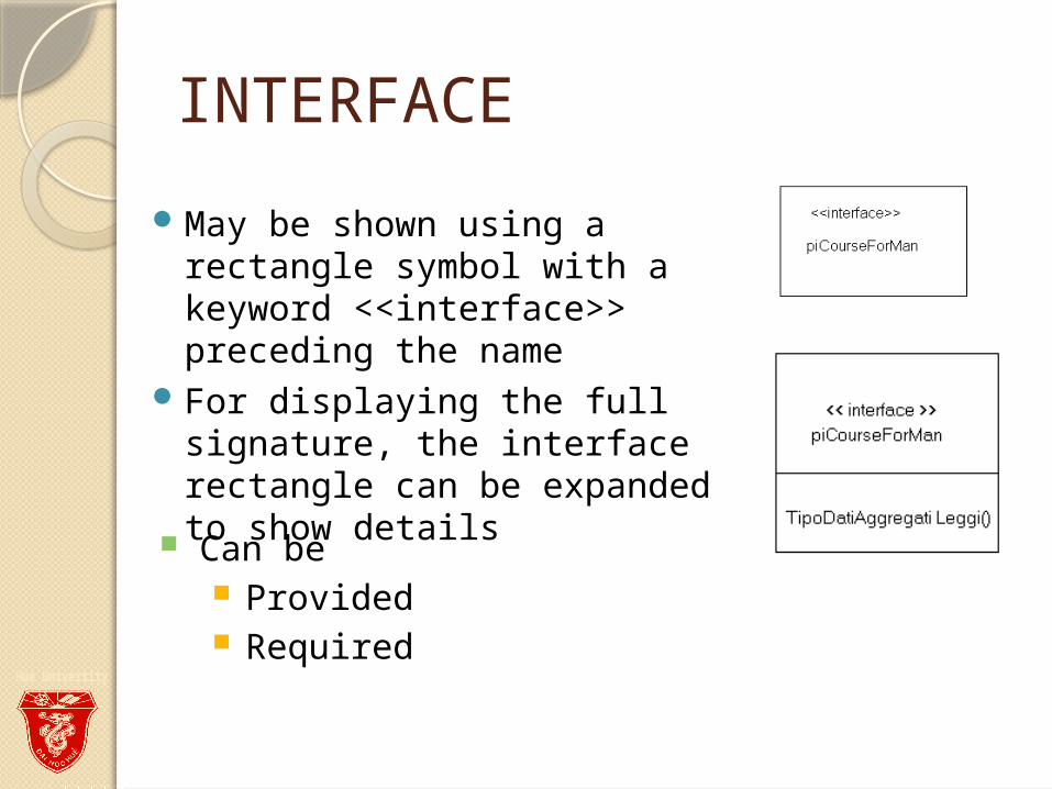
May be shown using a rectangle symbol with a keyword <<interface>> preceding the name
For displaying the full signature, the interface rectangle can be expanded to show details Can be
Provided Required
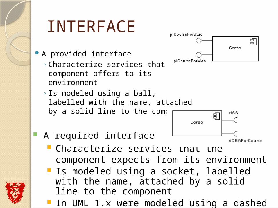
INTERFACEA provided interface
◦ Characterize services that the component offers to its environment
◦ Is modeled using a ball, labelled with the name, attached by a solid line to the component
A required interface Characterize services that the component
expects from its environment Is modeled using a socket, labelled with the
name, attached by a solid line to the component
In UML 1.x were modeled using a dashed arrow
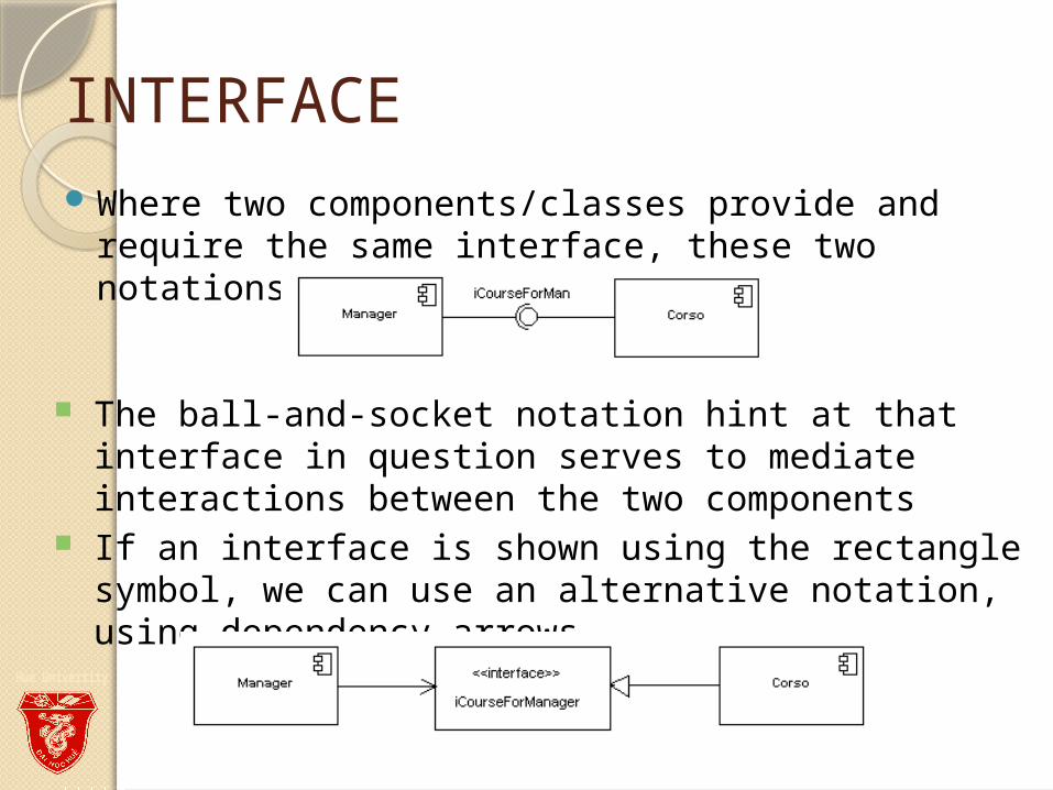
INTERFACEWhere two components/classes provide and
require the same interface, these two notations may be combined
The ball-and-socket notation hint at that interface in question serves to mediate interactions between the two components
If an interface is shown using the rectangle symbol, we can use an alternative notation, using dependency arrows
INTERFACE
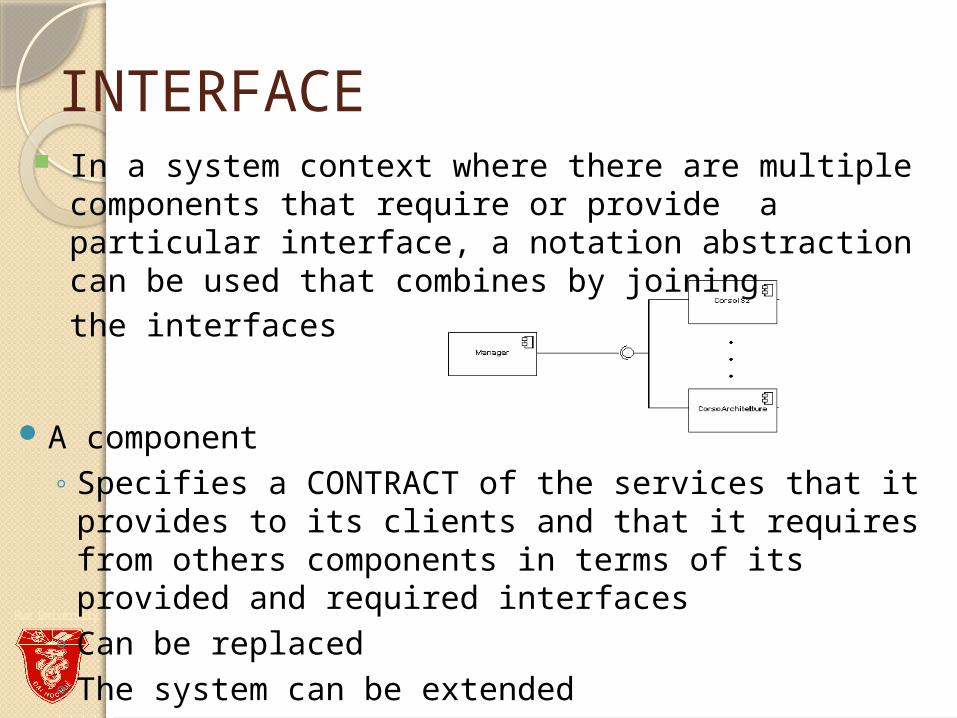
A component ◦ Specifies a CONTRACT of the services that it provides
to its clients and that it requires from others components in terms of its provided and required interfaces
◦ Can be replaced◦ The system can be extended
In a system context where there are multiple components that require or provide a particular interface, a notation abstraction can be used that combines by joining the interfaces
DEPENDENCIES
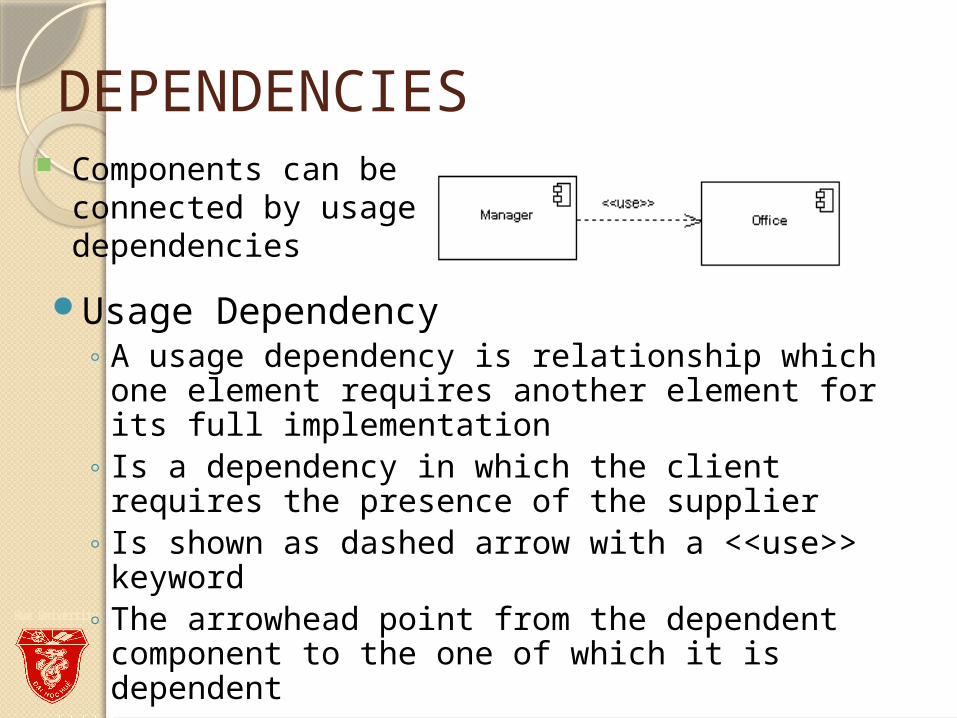
Usage Dependency ◦ A usage dependency is relationship which one
element requires another element for its full implementation
◦ Is a dependency in which the client requires the presence of the supplier
◦ Is shown as dashed arrow with a <<use>> keyword
◦ The arrowhead point from the dependent component to the one of which it is dependent
Components can be connected by usage dependencies
PORT
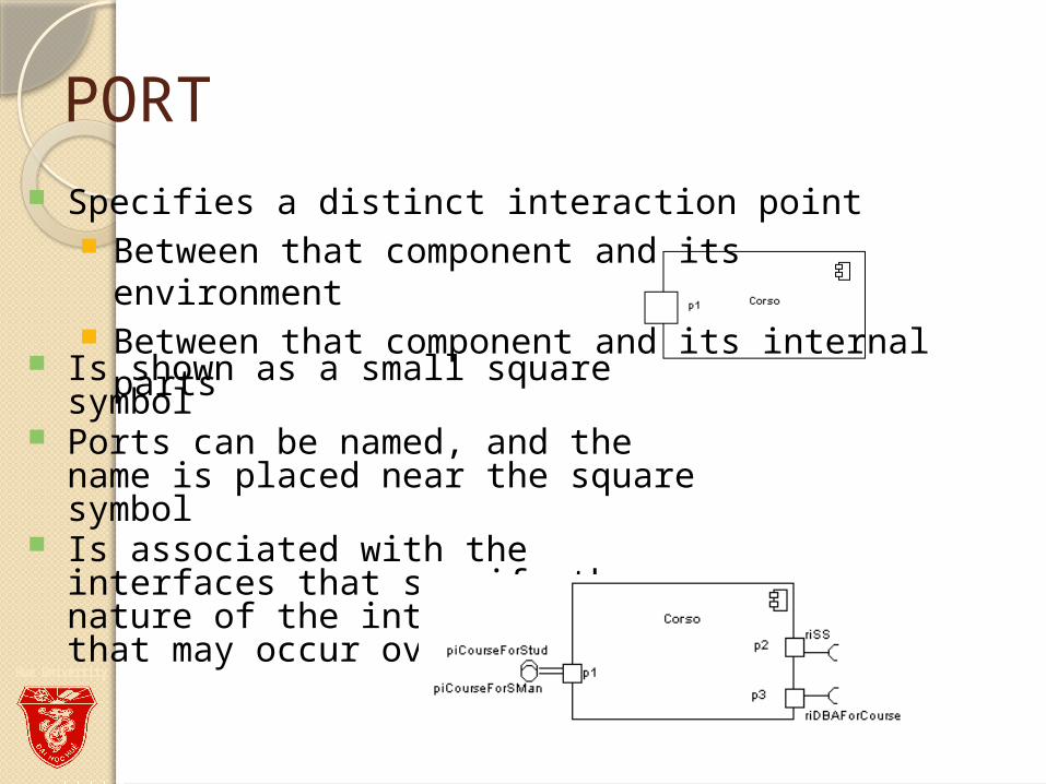
Is shown as a small square symbol Ports can be named, and the name
is placed near the square symbol Is associated with the interfaces
that specify the nature of the interactions that may occur over a port
Specifies a distinct interaction point Between that component and its environment Between that component and its internal parts
PORT
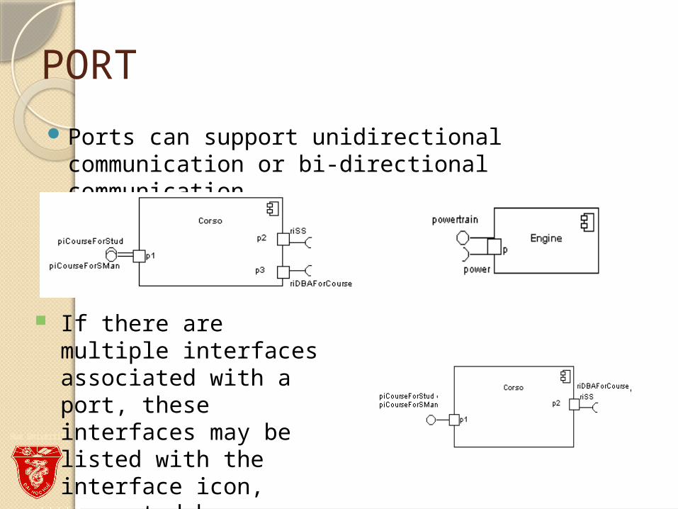
Ports can support unidirectional communication or bi-directional communication
If there are multiple interfaces associated with a port, these interfaces may be listed with the interface icon, separated by a commas
PORT◦All interactions of a component with
its environment are achieved through a port
◦The internals are fully isolated from the environment
◦This allows such a component to be used in any context that satisfies the constraints specified by its ports
◦Ports are not defined in UML 1.x
EXTERNAL VIEW
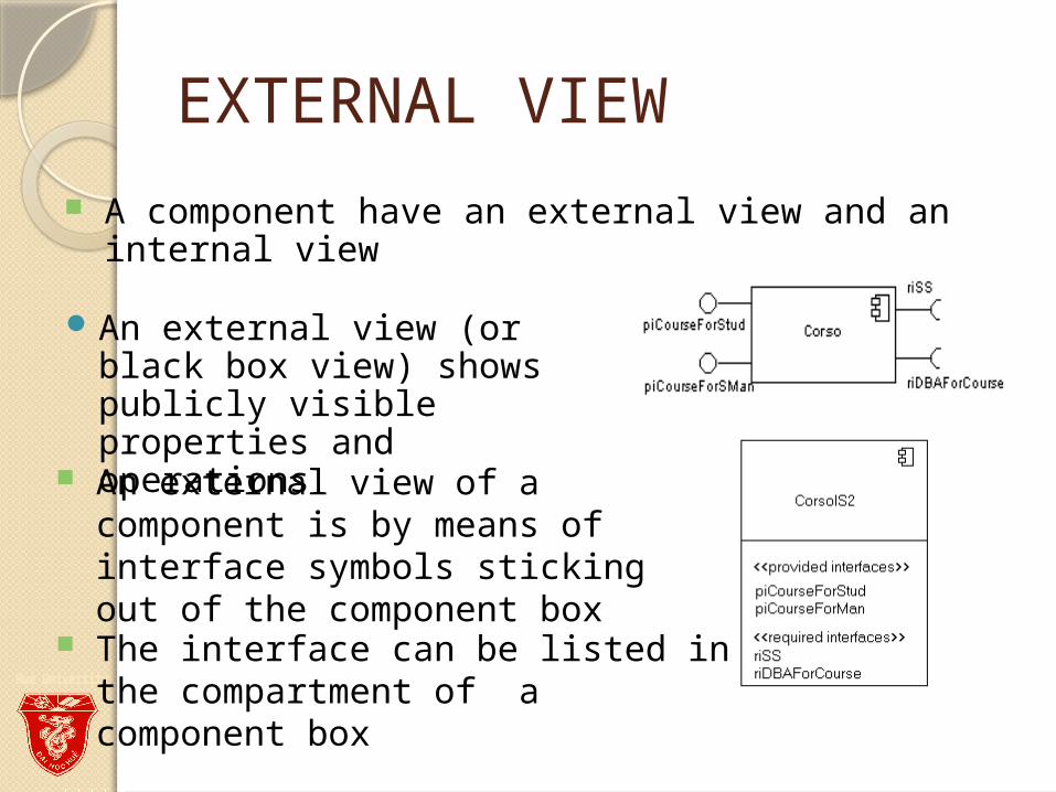
An external view (or black box view) shows publicly visible properties and operations
An external view of a component is by means of interface symbols sticking out of the component box
The interface can be listed in the compartment of a component box
A component have an external view and an internal view
INTERNAL VIEW
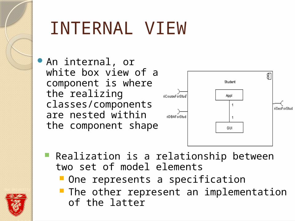
An internal, or white box view of a component is where the realizing classes/components are nested within the component shape
Realization is a relationship between two set of model elements One represents a specification The other represent an implementation of
the latter
INTERNAL VIEW
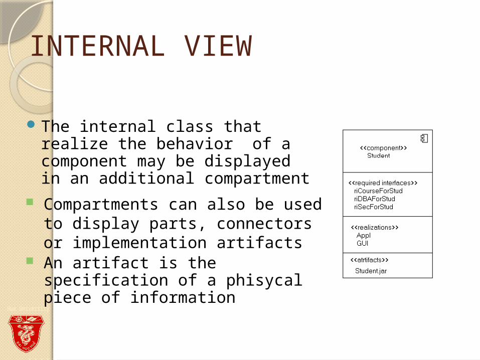
The internal class that realize the behavior of a component may be displayed in an additional compartment
Compartments can also be used to display parts, connectors or implementation artifacts
An artifact is the specification of a phisycal piece of information
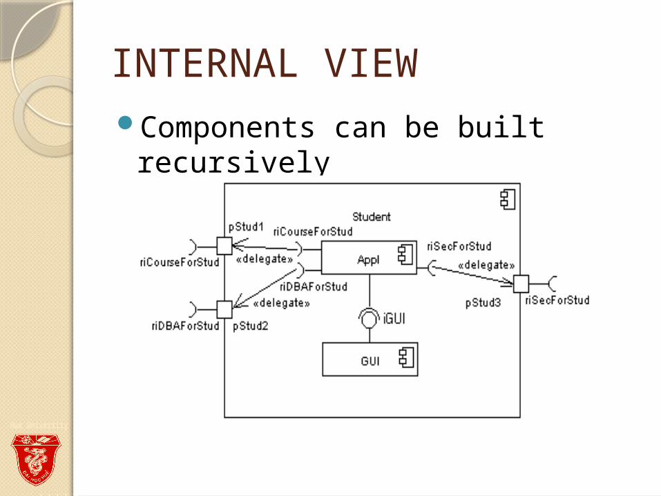
INTERNAL VIEWComponents can be built
recursively

ASSEMBLYTwo kinds of connectors:
◦ Delegation◦ Assembly
ASSEMBLY CONNECTOR◦ A connector between 2 components defines that
one component provides the services that another component requires
◦ He must only be defined from a required interface to a provided interface
◦ An assembly connector is notated by a “ball-and-socket” connection
This notation allows for succint graficalwiring of components
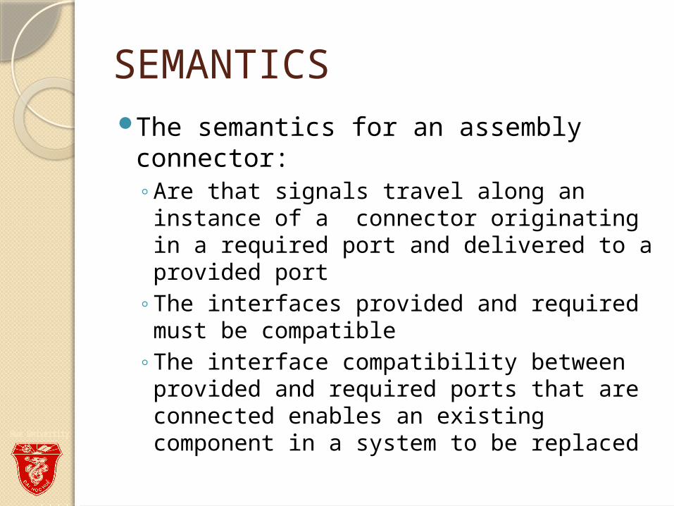
SEMANTICSThe semantics for an assembly
connector:◦Are that signals travel along an instance
of a connector originating in a required port and delivered to a provided port
◦The interfaces provided and required must be compatible
◦The interface compatibility between provided and required ports that are connected enables an existing component in a system to be replaced
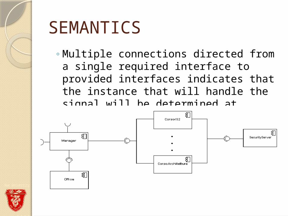
SEMANTICS◦Multiple connections directed from a
single required interface to provided interfaces indicates that the instance that will handle the signal will be determined at execution time
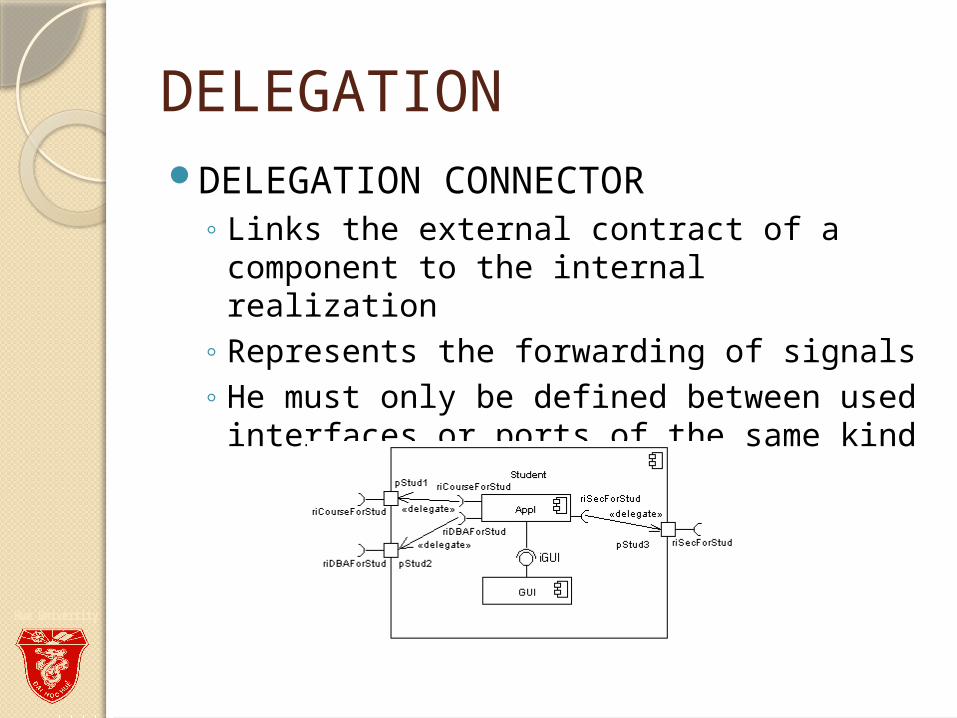
DELEGATIONDELEGATION CONNECTOR
◦ Links the external contract of a component to the internal realization
◦ Represents the forwarding of signals◦ He must only be defined between used
interfaces or ports of the same kind
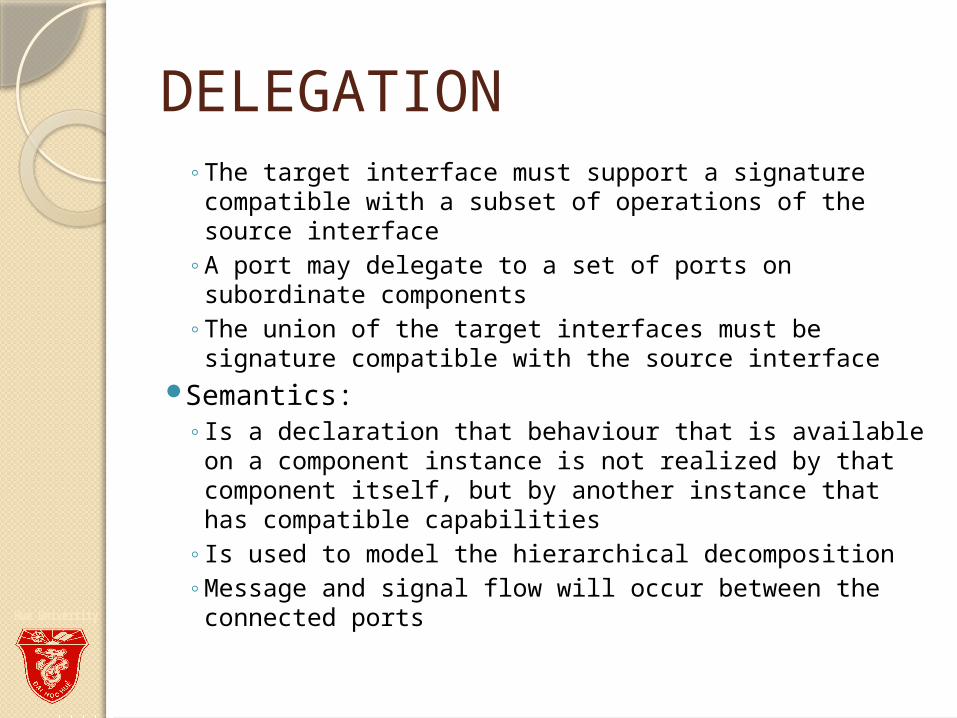
DELEGATION◦ The target interface must support a signature
compatible with a subset of operations of the source interface
◦ A port may delegate to a set of ports on subordinate components
◦ The union of the target interfaces must be signature compatible with the source interface
Semantics: ◦ Is a declaration that behaviour that is available on a
component instance is not realized by that component itself, but by another instance that has compatible capabilities
◦ Is used to model the hierarchical decomposition ◦ Message and signal flow will occur between the
connected ports
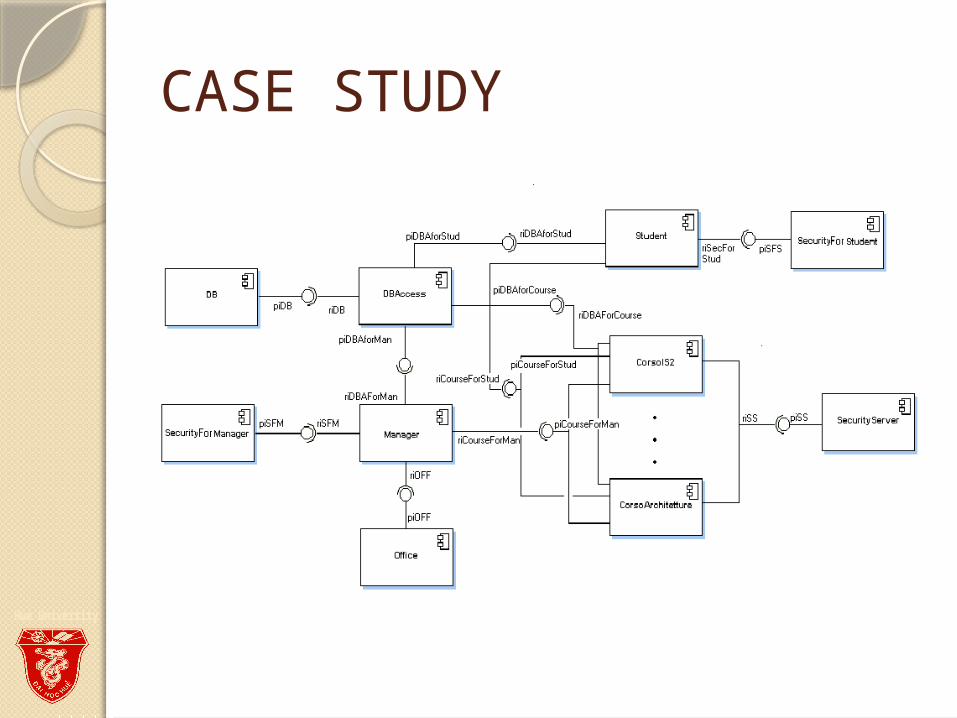
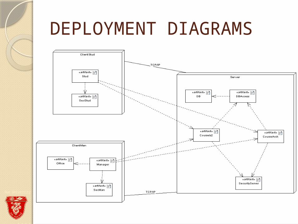
CASE STUDY
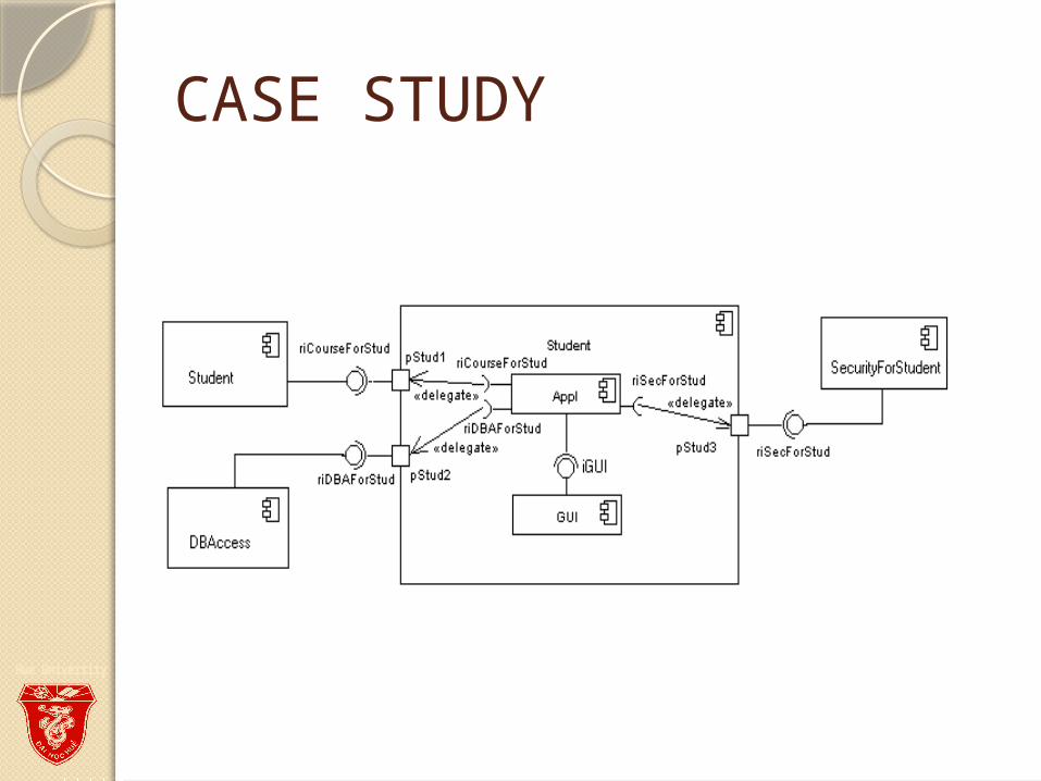
CASE STUDY
DEPLOYMENT DIAGRAMSThere is a strong link between
components diagrams and deployment diagrams
Deployment diagrams ◦Show the physical relationship between
hardware and software in a system◦Hardware elements:
Computers (clients, servers) Embedded processors Devices (sensors, peripherals)
◦Are used to show the nodes where software components reside in the run-time system
DEPLOYMENT DIAGRAMS
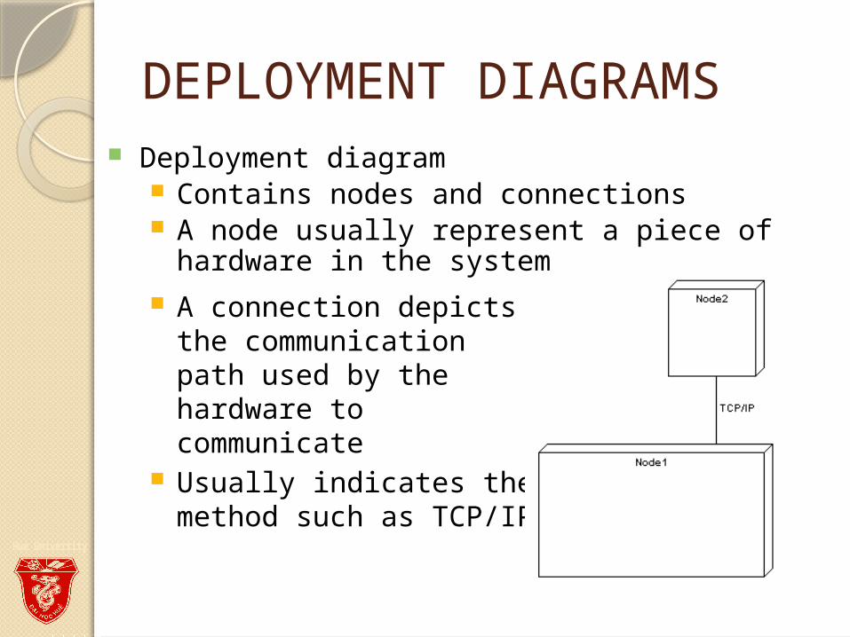
Deployment diagram Contains nodes and connections A node usually represent a piece of hardware
in the system A connection depicts the
communication path used by the hardware to communicate
Usually indicates the method such as TCP/IP
DEPLOYMENT DIAGRAMS
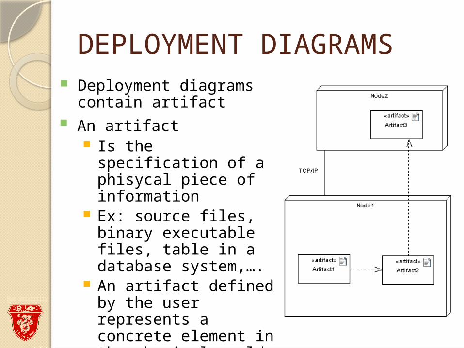
An artifact Is the specification of a
phisycal piece of information
Ex: source files, binary executable files, table in a database system,….
An artifact defined by the user represents a concrete element in the physical world
Deployment diagrams contain artifact
DEPLOYMENT DIAGRAMS
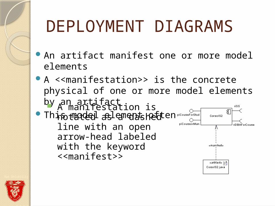
An artifact manifest one or more model elements
A <<manifestation>> is the concrete physical of one or more model elements by an artifact
This model element often is a component A manifestation is notated as a dashed line with an open arrow-head labeled with the keyword <<manifest>>
DEPLOYMENT DIAGRAMS
REFERENCIESUML 2.0 Superstructure Specification
August 2, 2003UML 2 Superstructure Final Adopted Specificationwww.omg.org/cgi-bin/doc?ptc/2003-08-02
The Diagrams of UML 2.0by Scott W. Ambler, 2003-2004 www.agilemodeling.com/essays/umlDiagrams.htm
UML overviewBy Mandar Chitnis, Pravin Tiwari, & Lakshmi Ananthamurthy http://www.developer.com/design/article.php/1553851