bushings - Daemar Incdaemar.com/wp-content/uploads/2013/11/Daemar-DMR-Bushing-Catalogue...main...
52
www.daemar.com BUSHINGS DMR TM
Transcript of bushings - Daemar Incdaemar.com/wp-content/uploads/2013/11/Daemar-DMR-Bushing-Catalogue...main...
www.daemar.com
bushings
DMRTM

For over 38 years Daemar®Inc. has remained focused on partnering with our customers to deliver precision component solutions that meet their business challenges. Whether the application is a new design or a maintenance requirement, Daemar’s global partnerships offer you one of the most complete sources of supply for Bushings. To ensure that Daemar® consistently meets or exceeds customer requirements, Daemar® is ISO-9001:2008 registered and most suppliers have either TS16949-2000, QS-9000 or ISO-9001:2000 quality registrations.
Daemar® has developed all of the capabilities required to support your lean manufacturing initiatives - providing JIT
delivery, vendor managed inventories and computer systems integration. Supported by the Daemar® regional warehousing network you experience fast, courteous service throughout the world. All of Daemar’s locations are fully stocked and staffed with experienced and knowledgeable sales & service professionals.
We trust that you will find this catalogue a valuable resource for selecting the appropriate Bushings for your applications. For further selection assistance, pricing and product availability please contact the Daemar® location nearest you.
1www.daemar.com
DMR
Quality - ISO 9002 Certification .. . . . . . . . . . . . . . . . . . . . . . . . . . . . . . . . . . . . . . . . . . . . . . . . . . . . . . . . . . . . . . . . . . . . . . . . . . . . . . . . . . . . . . . . . . . . . . . . . . . . . . . . . . . . . . . . . . . . . . . . . . . . . . . . . . . . . . . .2
Product List . . . . . . . . . . . . . . . . . . . . . . . . . . . . . . . . . . . . . . . . . . . . . . . . . . . . . . . . . . . . . . . . . . . . . . . . . . . . . . . . . . . . . . . . . . . . . . . . . . . . . . . . . . . . . . . . . . . . . . . . . . . . . . . . . . . . . . . . . . . . . . . . . . . . . . . . . . . . . . . . . .3
Interchange .. . . . . . . . . . . . . . . . . . . . . . . . . . . . . . . . . . . . . . . . . . . . . . . . . . . . . . . . . . . . . . . . . . . . . . . . . . . . . . . . . . . . . . . . . . . . . . . . . . . . . . . . . . . . . . . . . . . . . . . . . . . . . . . . . . . . . . . . . . . . . . . . . . . . . . . . . . . . . . . . .4
DryslideTM
TH - Self-Lubricating Bearings .. . . . . . . . . . . . . . . . . . . . . . . . . . . . . . . . . . . . . . . . . . . . . . . . . . . . . . . . . . . . . . . . . . . . . . . . . . . . . . . . . . . . . . . . . . . . . . . . . . . . . . . . . . . . . . . . . . . . . . . . . . . . . . . . . . . .5
THX - Pre-Lubricating Bearings .. . . . . . . . . . . . . . . . . . . . . . . . . . . . . . . . . . . . . . . . . . . . . . . . . . . . . . . . . . . . . . . . . . . . . . . . . . . . . . . . . . . . . . . . . . . . . . . . . . . . . . . . . . . . . . . . . . . . . . . . . . . . . . . . . . .6
TH - Inch Sizes . . . . . . . . . . . . . . . . . . . . . . . . . . . . . . . . . . . . . . . . . . . . . . . . . . . . . . . . . . . . . . . . . . . . . . . . . . . . . . . . . . . . . . . . . . . . . . . . . . . . . . . . . . . . . . . . . . . . . . . . . . . . . . . . . . . . . . . . . . . . . . . . . . . . . 7-10
FTH - Inch Sizes . . . . . . . . . . . . . . . . . . . . . . . . . . . . . . . . . . . . . . . . . . . . . . . . . . . . . . . . . . . . . . . . . . . . . . . . . . . . . . . . . . . . . . . . . . . . . . . . . . . . . . . . . . . . . . . . . . . . . . . . . . . . . . . . . . . . . . . . . . . . . . . . . . . . . . 11
TS & TW - Inch Sizes.. . . . . . . . . . . . . . . . . . . . . . . . . . . . . . . . . . . . . . . . . . . . . . . . . . . . . . . . . . . . . . . . . . . . . . . . . . . . . . . . . . . . . . . . . . . . . . . . . . . . . . . . . . . . . . . . . . . . . . . . . . . . . . . . . . . . . . . . . . . . . . 12
TH - Metric Sizes . . . . . . . . . . . . . . . . . . . . . . . . . . . . . . . . . . . . . . . . . . . . . . . . . . . . . . . . . . . . . . . . . . . . . . . . . . . . . . . . . . . . . . . . . . . . . . . . . . . . . . . . . . . . . . . . . . . . . . . . . . . . . . . . . . . . . . . . . . . . . . . . . 13-15
FTH - Metric Sizes . . . . . . . . . . . . . . . . . . . . . . . . . . . . . . . . . . . . . . . . . . . . . . . . . . . . . . . . . . . . . . . . . . . . . . . . . . . . . . . . . . . . . . . . . . . . . . . . . . . . . . . . . . . . . . . . . . . . . . . . . . . . . . . . . . . . . . . . . . . . . . . . . . . 16
TS & TW - Metric Sizes . . . . . . . . . . . . . . . . . . . . . . . . . . . . . . . . . . . . . . . . . . . . . . . . . . . . . . . . . . . . . . . . . . . . . . . . . . . . . . . . . . . . . . . . . . . . . . . . . . . . . . . . . . . . . . . . . . . . . . . . . . . . . . . . . . . . . . . . . . . . 17
THX (Sleeve Bushing) - Inch Sizes . . . . . . . . . . . . . . . . . . . . . . . . . . . . . . . . . . . . . . . . . . . . . . . . . . . . . . . . . . . . . . . . . . . . . . . . . . . . . . . . . . . . . . . . . . . . . . . . . . . . . . . . . . . . . . . . . . . . . . . . . . . . . . 18
THX (Thrust Washer) - Inch Sizes . . . . . . . . . . . . . . . . . . . . . . . . . . . . . . . . . . . . . . . . . . . . . . . . . . . . . . . . . . . . . . . . . . . . . . . . . . . . . . . . . . . . . . . . . . . . . . . . . . . . . . . . . . . . . . . . . . . . . . . . . . . . . . . 19
Design Notes
Technical Information .. . . . . . . . . . . . . . . . . . . . . . . . . . . . . . . . . . . . . . . . . . . . . . . . . . . . . . . . . . . . . . . . . . . . . . . . . . . . . . . . . . . . . . . . . . . . . . . . . . . . . . . . . . . . . . . . . . . . . . . . . . . . . . . . . . . . . . . . . . 20-21
PV Calculations . . . . . . . . . . . . . . . . . . . . . . . . . . . . . . . . . . . . . . . . . . . . . . . . . . . . . . . . . . . . . . . . . . . . . . . . . . . . . . . . . . . . . . . . . . . . . . . . . . . . . . . . . . . . . . . . . . . . . . . . . . . . . . . . . . . . . . . . . . . . . . . . . . . . . . . 22
Operating Life . . . . . . . . . . . . . . . . . . . . . . . . . . . . . . . . . . . . . . . . . . . . . . . . . . . . . . . . . . . . . . . . . . . . . . . . . . . . . . . . . . . . . . . . . . . . . . . . . . . . . . . . . . . . . . . . . . . . . . . . . . . . . . . . . . . . . . . . . . . . . . . . . . . . . 23-25
Installation Guide... . . . . . . . . . . . . . . . . . . . . . . . . . . . . . . . . . . . . . . . . . . . . . . . . . . . . . . . . . . . . . . . . . . . . . . . . . . . . . . . . . . . . . . . . . . . . . . . . . . . . . . . . . . . . . . . . . . . . . . . . . . . . . . . . . . . . . . . . . . . . . . 26-27
Fiber-LubeTM
Fiber-Lube Introduction .. . . . . . . . . . . . . . . . . . . . . . . . . . . . . . . . . . . . . . . . . . . . . . . . . . . . . . . . . . . . . . . . . . . . . . . . . . . . . . . . . . . . . . . . . . . . . . . . . . . . . . . . . . . . . . . . . . . . . . . . . . . . . . . . . . . . . . . . 28-29
Fiber-Lube™ - CJ Series . . . . . . . . . . . . . . . . . . . . . . . . . . . . . . . . . . . . . . . . . . . . . . . . . . . . . . . . . . . . . . . . . . . . . . . . . . . . . . . . . . . . . . . . . . . . . . . . . . . . . . . . . . . . . . . . . . . . . . . . . . . . . . . . . . . . . . . 32-40
Fiber-LubeTM - Inch Sizes . . . . . . . . . . . . . . . . . . . . . . . . . . . . . . . . . . . . . . . . . . . . . . . . . . . . . . . . . . . . . . . . . . . . . . . . . . . . . . . . . . . . . . . . . . . . . . . . . . . . . . . . . . . . . . . . . . . . . . . . . . . . . . . . . . . . . . 41-45
Fiber-LubeTM- Metric Sizes . . . . . . . . . . . . . . . . . . . . . . . . . . . . . . . . . . . . . . . . . . . . . . . . . . . . . . . . . . . . . . . . . . . . . . . . . . . . . . . . . . . . . . . . . . . . . . . . . . . . . . . . . . . . . . . . . . . . . . . . . . . . . . . . . . . . 46-47
Application Data Sheet . . . . . . . . . . . . . . . . . . . . . . . . . . . . . . . . . . . . . . . . . . . . . . . . . . . . . . . . . . . . . . . . . . . . . . . . . . . . . . . . . . . . . . . . . . . . . . . . . . . . . . . . . . . . . . . . . . . . . . . . . . . . . . . . . . . . . . . . . . . . . . . . . 48
COnTEnTs
2 www.daemar.com
DMR qualiTy
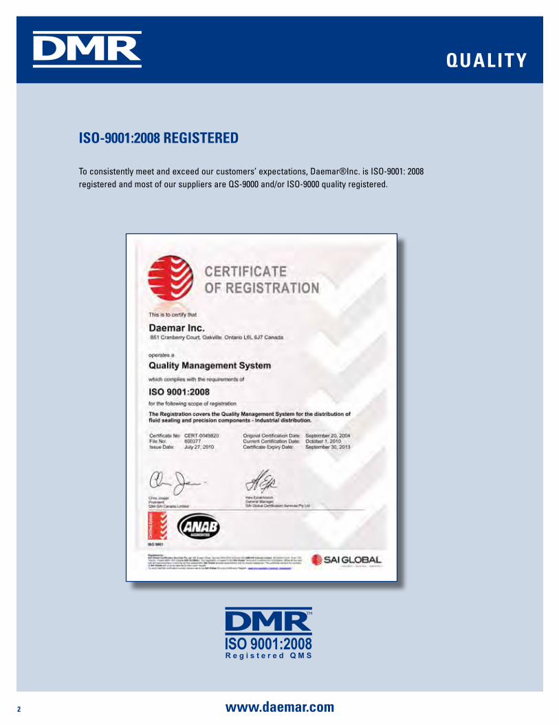
isO-9001:2008 REgisTEREd
To consistently meet and exceed our customers’ expectations, Daemar®Inc. is ISO-9001: 2008 registered and most of our suppliers are QS-9000 and/or ISO-9000 quality registered.

3www.daemar.com
DMR
daEmaR's COmplETE bushing pROduCT linE
dryslide™Self-Lubricated
Inch Sizes: TH, FTH, TS-TH & TW-THMetric Sizes: MB - TH, MB - FTH, TS - M, TW - M
Pre-LubricatedInch Sizes: THX, TS-THX, TW - THXMetric Sizes: MB-THX, TS-THX-M, TW - THX-M
Fiber-lube™FL - Series (Inch Sizes)FLM - Series (Metric Sizes)
Catalogue C0g-003
powdered metal bushings Flange Bushings Available in SAE841 and SAE 863
materials Sleeve Bushings Thrust Washers
linear motion LM76 Ceramic Series LM76 SL Series
Catalogue C0g-020
solid metal bushings Flange Bushings Sleeve Bushings Thrust Washers
Contact a daemar sales representative for further
information on sizes available for these parts
and to request a catalogue
products covered in this catalogue
Catalogue C0g-020
Catalogue C0g-030
pROduCT lisT
4 www.daemar.com
DMR
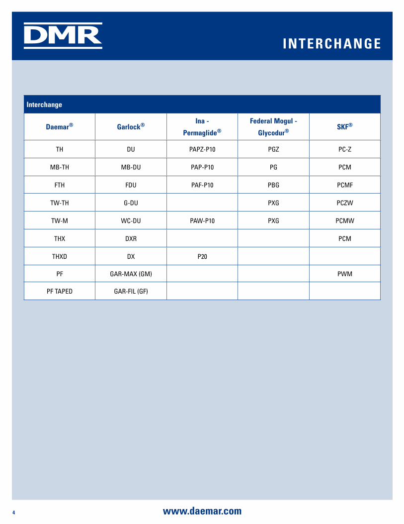
interchange
daemar® garlock®ina -
permaglide®
Federal mogul -
glycodur®sKF®
TH DU PAPZ-P10 PGZ PC-Z
MB-TH MB-DU PAP-P10 PG PCM
FTH FDU PAF-P10 PBG PCMF
TW-TH G-DU PXG PCZW
TW-M WC-DU PAW-P10 PXG PCMW
THX DXR PCM
THXD DX P20
PF GAR-MAX (GM) PWM
PF TAPED GAR-FIL (GF)
inTERChangE

5www.daemar.com
DMR
The Dryslide trademark identifies a whole range of self-lubricated dry sliding bearings. A composite structure, TH consists of a carbon steel backing, an intermediate
layer of sintered bronze, PTFE based sliding lining. The main items in the TH range are the wrapped cylindrical bushings (DIN 1494) and the flanged cylindrical bushings. Moreover, the range also includes thrust washers, strips and special parts made to customer specifications. From a technical point of view, the product is already widely known and new applications are constantly being identified to take advantage of the high load capacity, the self-lubricated feature and the excellent ratio between cost and performance of the whole range.
pROduCT sTRuCTuREsteel bronze powder with pTFE/Fibres mixture (lead Free)
1. pTFE based mixture 0.01-0.03mm: provides an excellent initial transfer film, which effectively coats the mating surface of the bearing assembly, forming an oxide type solid lubricant film.
2. sintered bronze powder 0.20-0.35mm: provides maximum thermal conductivity away from the bearing surface, also serves as a reservoir for the PTFE based mixture.
3. low-Carbon steel: provides exceptionally high load carrying capacity.
4. Copper/Tin plating 0.002mm: provides good corrosion resistance.
A dry running bearing with a low coefficient of friction, good wear properties and sliding characteristics. It can be used in both rotary and oscillating applications.
TypiCal appliCaTiOnsCan meet the demanding criteria for long life and trouble-free performance with or without lubrication.
automotive: tractors, combines, crop sprayers, earthmovers, and road graders. Specific uses in power steering cylinders, steering gear thrust washers, disc brakes, callipers, pistons, shock absorbers, governor linkage, windshield wiper motor, and tilt gear assemblies...
Office Equipment: photocopy machines, mail sorters, postage meter systems, computer printers, peripheral equipment, automatic printing devices, and mail processing machinery...
hydraulics and valves: pumps including gear, rotary, water, axial piston, and other types, ball, butterfly, poppet steam, and other valves and valve trunnions...
home appliances: refrigerators, air conditioners, vacuum cleaners, polishers, sewing machines, ovens, dishwashers, and washing machines...
materials handling: pallet trucks, scissor lifts, packaging machinery and textile equipment...
Technical data
max. load
static 250 n/mm2 (36,000 psi)
Very slow speeds 140 n/mm2 (20,000 psi)
Rotating / Oscillating 60 n/mm2 (8,400 psi)
max. pV dry Running
short term Operation 3.6 n/mm2*m/s (102,000 psi-fpm)
Continuous Operation 1.8 n/mm2*m/s(51,000 psi-fpm)
Temperature Range (°C) -195°C to +280°C(-319°F to +536°F)
max. speeddry Running 2 m/s (400 fpm)
hydrodynamic Operation > 2 m/s (> 400 fpm)
Thermal Conductivity 42 W(m*K)-1
302 bTu/(hr)(ft2)(°F/in)
Coefficient of Thermal Expansion 11*10-6*K-1
Coefficient of Friction 0.03 - 0.20
1
2
3
4
TH inTROduCTiOnsElF-lubRiCaTing bEaRings

6 www.daemar.com
DMR
pROduCT sTRuCTuREsteel bronze powder with acetal marginal bearings
1. pOm (acetal) 0.30-0.50mm: has high wear resistance and low friction. The bearing surface has a pattern of circular indents, which should be filled with grease on assembly.
2. sintered bronze powder 0.20-0.35mm: provides maximum thermal conductivity away from the bearing surface, also serves as a reservoir for the resin mixture.
3. low-Carbon steel: provides exceptionally high load carrying capacity.
4. Copper/Tin plating 0.002mm: provides good corrosion resistance.
The THX bushing can be used in rotary and oscillating applications. Less maintenance requirements due to the long re-lubrication intervals. Less wear, less susceptibility to edge loading, and no absorption of water. The THX has good damping qualities and is resistant to shock loads.
TypiCal appliCaTiOnsRecommended for applications involving intermittent operation or boundary lubrication.
automotive: suspension joints, kingpin assemblies, automobile driving joint hinges, steering and other linkages, articulation joints, and rear chassis hinges.
machine Tools: spindles in drill, grinding, and milling machines, and ram guide plates in multi ram presses.
agricultural Equipment: gearboxes, clutch assemblies, bale trips and wheel caster swivels for bale accumulators, front axle pivot bearings, steering idler box bearings and kingpin bearings for harvesters...
The THX bushing is especially well suited for applications where lubricant cannot be supplied continuously or repeatedly.
Technical data
max. load static 250 n/mm2 (36,000 psi)
load Capacity 140 n/mm2 (20,000 psi)
max. pV3.0 n/mm2*m/s (85,000 psi-Fpm)
Temperature Range-40°C to +130°C(-40°F to +260°F)
max. speed greased 0.5 m/s (100 Fpm)
Oiled 2.5 m/s (500 Fpm)
Coefficient of Friction 0.05 - 0.20
The THX trademark denotes a range of sliding bearings produced from a material with a composite structure. The backing consists of carbon steel onto which a porous layer of bronze is sintered and then impregnated with a co-acetal plastic. The polymeric surface has indentations in which the lubricating grease lies and protects the mating surface. The main products in the THX range are the cylindrical bushings (DIN 1494), but thrust washers and strips are also available as well as special parts made to customer specifications.
THX inTROduCTiOnpRE-lubRiCaTing bEaRings
lubrication pocket
1
2
3
4
7www.daemar.com
DMR
part number
d1 d2length
(+/- 0.010”)
shaft diameter
(d)
housing bore (dg)
installed id
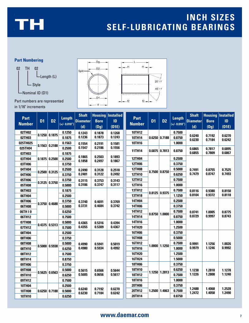
(d1E)02Th02
0.1250 0.18750.1250 0.1243
0.12360.18780.1873
0.12680.124302Th03 0.1875
025Th0250.1563 0.2188
0.1563 0.15540.1547
0.21910.2186
0.15810.1556025Th04 0.2500
03Th030.1875 0.2500
0.18750.18650.1858
0.25030.2497
0.18930.186703Th04 0.2500
03Th06 0.375004Th04
0.2500 0.31250.2500 0.2490
0.24810.31280.3122
0.25180.249204Th06 0.3750
05Th060.3125 0.3750
0.3750 0.31150.3106
0.37530.3747
0.31430.311705Th08 0.5000
06Th03
0.3750 0.4688
0.1875
0.37400.3731
0.46910.4684
0.37690.3742
06Th04 0.250006Th06 0.375006Th08 0.500006Th i 0 0.625006Th12 0.750007Th08
0.4375 0.53130.5000 0.4365
0.43550.53160.5309
0.43940.436707Th12 0.7500
08Th04
0.5000 0.5938
0.2500
0.49900.4980
0.59410.5934
0.50190.4992
08Th06 0.375008Th08 0.500008Th10 0.625008Th12 0.750008Th14 0.875009Th06
0.5625 0.6563
0.3750
0.56150.5605
0.65660.0656
0.56440.5617
09Th08 0.500009Th10 0.625009Th12 0.750010Th04
0.6250 0.71880.2500
0.62400.6230
0.71920.7184
0.62700.624210Th08 0.5000
10Th10 0.6250
part numbering
02 TH 02
Length (L)
Style
Nominal ID (D1)
Part numbers are represented in 1/16" increments
Split
Dg
D2
d
D1
L
f1
f2
20˚`5˚
45˚`5˚
f1
f2
part number
d1 d2length
(+/- 0.010”)
shaft diameter
(d)
housing bore (dg)
installed id
(d1E)10Th12
0.6250 0.71880.7500
0.62400.6230
0.71920.7184
0.62700.624210Th14 0.8750
10Th16 1.0000
11Th14 0.6875 0.7813 0.8750 0.68650.6855
0.78170.7809
0.68950.6867
12Th04
0.7500 0.8750
0.2500
0.74910.7479
0.87550.8747
0.75250.7493
12Th06 0.375012Th08 0.500012Th10 0.625012Th12 0.750012Th16 1.000013Th12
0.8125 0.93750.7500 0.8116
0.81040.93800.9372
0.81500.811813Th18 1.1250
14Th04
0.8750 1.0000
0.2500
0.87410.8729
1.00050.9997
0.87750.8743
14Th06 0.375014Th12 0.750014Th14 0.875014Th16 1.000014Th20 1.250016Th06
1.0000 1.1250
0.3750
0.99910.9979
1.12561.1246
1.00260.9992
16Th08 0.500016Th12 0.750016Th16 1.000016Th20 1.250016Th24 1.500018Th06
1.1250 1.2813
0.3750
1.12381.1226
1.28181.2808
1.12781.1240
18Th10 0.625018Th12 0.750018Th16 1.000020Th06
1.2500 1.40630.3750
1.24881.2472
1.40681.4058
1.25281.249020Th12 0.7500
20Th14 0.8750
TH inCh sizEssElF-lubRiCaTing bEaRings
8 www.daemar.com
DMR
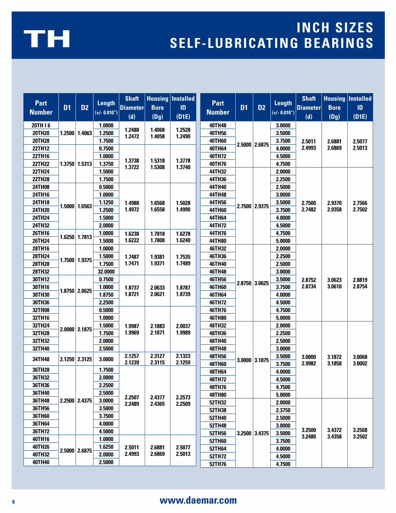
part number
d1 d2length
(+/- 0.010”)
shaft diameter
(d)
housing bore (dg)
installed id
(d1E)20Th i 6
1.2500 1.40631.0000
1.24881.2472
1.40681.4058
1.25281.249020Th20 1.2500
20Th28 1.750022Th12
1.3750 1.5313
0.7500
1.37381.3722
1.53181.5308
1.37781.3740
22Th16 1.000022Th22 1.375022Th24 1.500022Th28 1.750024Th08
1.5000 1.6563
0.5000
1.49881.4972
1.65681.6558
1.50281.4990
24Th16 1.000024Th18 1.125024Th20 1.250024Th24 1.500024Th32 2.000026Th16
1.6250 1.78131.0000 1.6238
1.62221.78181.7808
1.62781.624026Th24 1.5000
28Th16
1.7500 1.9375
1.00001.74871.7471
1.93811.9371
1.75351.7489
28Th24 1.500028Th28 1.750028Th32 32.000030Th12
1.8750 2.0625
0.75001.87371.8721
2.06332.0621
1.87871.8739
30Th16 1.000030Th30 1.875030Th36 2.250032Th08
2.0000 2.1875
0.5000
1.99871.9969
2.18832.1871
2.00371.9989
32Th16 1.000032Th24 1.500032Th28 1.750032Th32 2.000032Th40 2.5000
34Th48 2.1250 2.3125 3.0000 2.12572.1239
2.31272.3115
2.13232.1259
36Th28
2.2500 2.4375
1.7500
2.25072.2489
2.43772.4365
2.25732.2509
36Th32 2.000036Th36 2.250036Th40 2.500036Th48 3.000036Th56 3.500036Th60 3.750036Th64 4.000036Th72 4.500040Th16
2.5000 2.6875
1.00002.50112.4993
2.68812.6869
2.50772.5013
40Th26 1.625040Th32 2.000040Th40 2.5000
part number
d1 d2length
(+/- 0.010”)
shaft diameter
(d)
housing bore (dg)
installed id
(d1E)40Th48
2.5000 2.6875
3.0000
2.50112.4993
2.68812.6869
2.50772.5013
40Th56 3.500040Th60 3.750040Th64 4.000040Th72 4.500040Th76 4.750044Th32
2.7500 2.9375
2.0000
2.75002.7482
2.93702.9358
2.75662.7502
44Th36 2.250044Th40 2.500044Th48 3.000044Th56 3.500044Th60 3.750044Th64 4.000044Th72 4.500044Th76 4.750044Th80 5.000046Th32
2.8750 3.0625
2.0000
2.87522.8734
3.06233.0610
2.88192.8754
46Th36 2.250046Th40 2.500046Th48 3.000046Th56 3.500046Th60 3.750046Th64 4.000046Th72 4.500046Th76 4.750046Th80 5.000048Th32
3.0000 3.1875
2.0000
3.00002.9982
3.18723.1858
3.00683.0002
48Th36 2.250048Th40 2.500048Th48 3.000048Th56 3.500048Th60 3.750048Th64 4.000048Th72 4.500048Th76 4.750048Th80 5.000052Th32
3.2500 3.4375
2.0000
3.25003.2480
3.43723.4358
3.25683.2502
52Th38 2.375052Th40 2.500052Th48 3.000052Th56 3.500052Th60 3.750052Th64 4.000052Th72 4.500052Th76 4.7500
TH inCh sizEssElF-lubRiCaTing bEaRings
9www.daemar.com
DMR
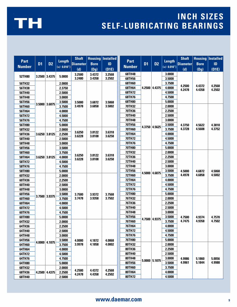
part number
d1 d2length
(+/- 0.010”)
shaft diameter
(d)
housing bore (dg)
installed id
(d1E)
52Th80 3.2500 3.4375 5.0000 3.25003.2480
3.43723.4358
3.25683.2502
56Th32
3.5000 3.6875
2.0000
3.50003.4978
3.68723.6858
3.50683.5002
56Th38 2.375056Th40 2.500056Th48 3.000056Th56 3.500056Th60 3.750056Th64 4.000056Th72 4.500056Th76 4.750056Th80 5.000058Th32
3.6250 3.81252.0000
3.62503.6228
3.81223.8108
3.63183.625858Th36 2.2500
58Th40 2.500058Th48
3.6250 3.8125
3.0000
3.62503.6228
3.81223.8108
3.63183.6258
58Th56 3.500058Th60 3.750058Th64 4.000058Th72 4.500058Th76 4.750058Th80 5.000060Th32
3.7500 3.9375
2.0000
3.75003.7478
3.93723.9358
3.75683.7502
60Th36 2.250060Th40 2.500060Th48 3.000060Th56 3.500060Th60 3.750060Th64 4.000060Th72 4.500060Th76 4.750060Th80 5.000064Th32
4.0000 4.1875
2.0000
4.00003.9978
4.18724.1858
4.00684.0002
64Th36 2.250064Th40 2.500064Th48 3.000064Th56 3.500064Th60 3.750064Th64 4.000064Th72 4.500064Th76 4.750064Th80 5.000068Th32
4.2500 4.43752.0000
4.25004.2478
4.43724.4358
4.25684.250268Th36 2.2500
68Th40 2.5000
part number
d1 d2length
(+/- 0.010”)
shaft diameter
(d)
housing bore (dg)
installed id
(d1E)68Th48
4.2500 4.4375
3.0000
4.25004.2478
4.43724.4358
4.25684.2502
68Th56 3.500068Th60 3.750068Th64 4.000068Th72 4.500068Th76 4.750068Th80 5.000070Th32
4.3750 4.5625
2.0000
4.37504.3728
4.56224.5608
4.38184.3752
70Th36 2.250070Th40 2.500070Th48 3.000070Th56 3.500070Th60 3.750070Th64 4.000070Th72 4.500070Th76 4.750070Th80 5.000072Th32
4.5000 4.6875
2.0000
4.50004.4978
4.68724.6858
4.50684.5002
72Th36 2.250072Th40 2.500072Th48 3.000072Th56 3.500072Th60 3.750072Th64 4.000072Th72 4.500072Th76 4.750072Th80 5.000076Th32
4.7500 4.9375
2.0000
4.75004.7475
4.93744.9358
4.75704.7502
76Th36 2.250076Th40 2.500076Th48 3.000076Th56 3.500076Th60 3.750076Th64 4.000076Th72 4.500076Th76 4.750076Th80 5.000080Th32
5.0000 5.1875
2.0000
4.99864.9961
5.18605.1844
5.00564.9988
80Th36 2.250080Th40 2.500080Th48 3.000080Th56 3.500080Th60 3.750080Th64 4.000080Th72 4.5000
TH inCh sizEssElF-lubRiCaTing bEaRings
10 www.daemar.com
DMR
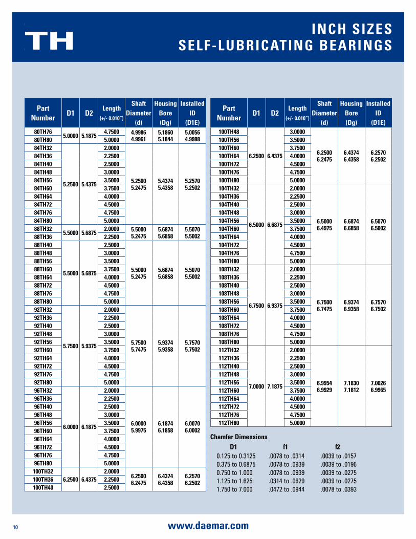
part number
d1 d2length
(+/- 0.010”)
shaft diameter
(d)
housing bore (dg)
installed id
(d1E)80Th76
5.0000 5.18754.7500 4.9986
4.99615.18605.1844
5.00564.998880Th80 5.0000
84Th32
5.2500 5.4375
2.0000
5.25005.2475
5.43745.4358
5.25705.2502
84Th36 2.250084Th40 2.500084Th48 3.000084Th56 3.500084Th60 3.750084Th64 4.000084Th72 4.500084Th76 4.750084Th80 5.000088Th32
5.5000 5.68752.0000 5.5000
5.24755.68745.6858
5.50705.500288Th36 2.2500
88Th40
5.5000 5.6875
2.5000
5.50005.2475
5.68745.6858
5.50705.5002
88Th48 3.000088Th56 3.500088Th60 3.750088Th64 4.000088Th72 4.500088Th76 4.750088Th80 5.000092Th32
5.7500 5.9375
2.0000
5.75005.7475
5.93745.9358
5.75705.7502
92Th36 2.250092Th40 2.500092Th48 3.000092Th56 3.500092Th60 3.750092Th64 4.000092Th72 4.500092Th76 4.750092Th80 5.000096Th32
6.0000 6.1875
2.0000
6.00005.9975
6.18746.1858
6.00706.0002
96Th36 2.250096Th40 2.500096Th48 3.000096Th56 3.500096Th60 3.750096Th64 4.000096Th72 4.500096Th76 4.750096Th80 5.0000
100Th326.2500 6.4375
2.00006.25006.2475
6.43746.4358
6.25706.2502100Th36 2.2500
100Th40 2.5000
part number
d1 d2length
(+/- 0.010”)
shaft diameter
(d)
housing bore (dg)
installed id
(d1E)100Th48
6.2500 6.4375
3.0000
6.25006.2475
6.43746.4358
6.25706.2502
100Th56 3.5000100Th60 3.7500100Th64 4.0000100Th72 4.5000100Th76 4.7500100Th80 5.0000104Th32
6.5000 6.6875
2.0000
6.50006.4975
6.68746.6858
6.50706.5002
104Th36 2.2500104Th40 2.5000104Th48 3.0000104Th56 3.5000104Th60 3.7500104Th64 4.0000104Th72 4.5000104Th76 4.7500104Th80 5.0000108Th32
6.7500 6.9375
2.0000
6.75006.7475
6.93746.9358
6.75706.7502
108Th36 2.2500108Th40 2.5000108Th48 3.0000108Th56 3.5000108Th60 3.7500108Th64 4.0000108Th72 4.5000108Th76 4.7500108Th80 5.0000112Th32
7.0000 7.1875
2.0000
6.99546.9929
7.18307.1812
7.00266.9965
112Th36 2.2500112Th40 2.5000112Th48 3.0000112Th56 3.5000112Th60 3.7500112Th64 4.0000112Th72 4.5000112Th76 4.7500112Th80 5.0000
Chamfer dimensionsd1 f1 f2
0.125 to 0.3125 .0078 to .0314 .0039 to .01570.375 to 0.6875 .0078 to .0939 .0039 to .01960.750 to 1.000 .0078 to .0939 .0039 to .02751.125 to 1.625 .0314 to .0629 .0039 to .02751.750 to 7.000 .0472 to .0944 .0078 to .0393
TH inCh sizEssElF-lubRiCaTing bEaRings
11www.daemar.com
DMR
SplitL
D3dD2 Dg D1
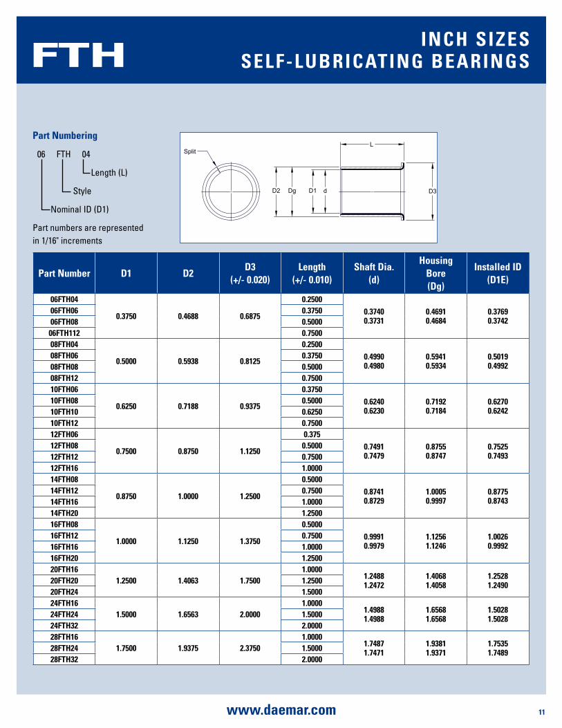
part number d1 d2d3
(+/- 0.020)length
(+/- 0.010)shaft dia.
(d)
housing bore (dg)
installed id (d1E)
06FTh04
0.3750 0.4688 0.6875
0.25000.37400.3731
0.46910.4684
0.37690.3742
06FTh06 0.375006FTh08 0.500006FTh112 0.750008FTh04
0.5000 0.5938 0.8125
0.25000.49900.4980
0.59410.5934
0.50190.4992
08FTh06 0.375008FTh08 0.500008FTh12 0.750010FTh06
0.6250 0.7188 0.9375
0.37500.62400.6230
0.71920.7184
0.62700.6242
10FTh08 0.500010FTh10 0.625010FTh12 0.750012FTh06
0.7500 0.8750 1.1250
0.3750.74910.7479
0.87550.8747
0.75250.7493
12FTh08 0.500012FTh12 0.750012FTh16 1.000014FTh08
0.8750 1.0000 1.2500
0.50000.87410.8729
1.00050.9997
0.87750.8743
14FTh12 0.750014FTh16 1.000014FTh20 1.250016FTh08
1.0000 1.1250 1.3750
0.50000.99910.9979
1.12561.1246
1.00260.9992
16FTh12 0.750016FTh16 1.000016FTh20 1.250020FTh16
1.2500 1.4063 1.75001.0000
1.24881.2472
1.40681.4058
1.25281.249020FTh20 1.2500
20FTh24 1.500024FTh16
1.5000 1.6563 2.00001.0000
1.49881.4988
1.65681.6568
1.50281.502824FTh24 1.5000
24FTh32 2.000028FTh16
1.7500 1.9375 2.37501.0000
1.74871.7471
1.93811.9371
1.75351.748928FTh24 1.5000
28FTh32 2.0000
FTH inCh sizEssElF-lubRiCaTing bEaRings
part numbering
06 FTH 04
Length (L)
Style
Nominal ID (D1)
Part numbers are represented in 1/16" increments
12 www.daemar.com
DMR
L
B2
S
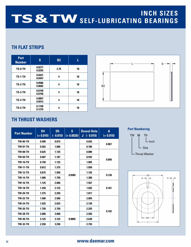
part numberd4
(+ 0.010)d5
(- 0.010)s
(+ 0.0020)dowel hole J (- 0.010)
a (+ 0.010)
TW-06-Th 0.500 0.875
0.0585
0.6920.067
TW-07-Th 0.562 1.000 0.786
TW-08-Th 0.625 1.125 0.880
0.099TW-09-Th 0.687 1.187 0.942
TW-10-Th 0.750 1.125 1.005
TW-11-Th 0.812 1.375 1.099
TW-12-Th 0.875 1.500 1.1920.130
TW-14-Th 1.000 1.750 1.380
TW-16-Th 1.125 2.000 1.567
0.161TW-18-Th 1.250 2.125 1.692
TW-20-Th 1.375 2.250 1.817
TW-22-Th 1.500 2.500 2.005
0.192
TW-24-Th 1.625 2.625 2.130
TW-26-Th 1.750 2.750 2.255
TW-28-Th 2.000 3.000
0.0895
2.505
TW-30-Th 2.125 3.125 2.630
TW-32-Th 2.250 3.250 2.755
part number
s b2 l
Ts-0-Th 0.02770.0293 2.75 18
Ts-1-Th 0.04310.0447 4 18
Ts-2-Th 0.05860.0602 4 18
Ts-3-Th 0.07400.0756 4 18
Ts-4-Th 0.08970.0913 4 18
Ts-5-Th 0.11900.1210 4 18
D5
D4
J
A S
Th ThRusT WashERs
Th FlaT sTRips
TS & TW inCh sizEssElF-lubRiCaTing bEaRings
part numbering
TW 06 TH
Inch
Size
Thrust Washer

13www.daemar.com
DMR
part number d1 d2length
(+/- 0.25)
shaft dia. (d)
housing bore (dg)
installed id
(d1E)mb030453-Th
3 4.5
3
2.9943.000
4.5004.508
3.0003.048
mb030454-Th 4mb030455-Th 5mb030456-Th 6mb040553-Th
4 5.5
3
3.9924.000
5.0005.508
4.0004.048
mb040554-Th 4mb040556-Th 6
mb0405510-Th 10mb05075-Th
5 75
4.9784.990
7.0007.015
4.9905.055
mb05078-Th 8mb050710-Th 10mb06084-Th
6 8
4
5.9785.990
8.0008.015
5.9906.055
mb06086-Th 6mb06088-Th 8
mb060810-Th 10
mb070910-Th 7 9 106.9726.987
9.0009.015
6.9907.055
mb08106-Th
8 10
6
7.9727.987
10.00010.015
7.9908.055
mb08108-Th 8mb081010-Th 10mb081012-Th 12mb10128-Th
10 12
8
9.9729.987
12.00012.018
9.99010.058
mb101210-Th 10mb101212-Th 12mb101215-Th 15mb101220-Th 20mb12148-Th
12 14
8
11.96611.984
14.00014.018
11.99012.058
mb121410-Th 10mb121412-Th 12mb121415-Th 15mb121420-Th 20mb121425-Th 25
part number d1 d2length
(+/- 0.25)
shaft dia. (d)
housing bore (dg)
installed id
(d1E)mb131510-Th
13 1510 12.966
12.98415.00015.018
12.99013.058mb131520-Th 20
mb14165-Th
14 16
5
13.96613.984
16.00016.018
13.99014.058
mb141610-Th 10mb141612-Th 12mb141615-Th 15mb141620-Th 20mb141625-Th 25mb151710-Th
15 17
10
14.96614.984
17.00017.018
14.99015.058
mb151712-Th 12mb151715-Th 15mb151720-Th 20mb151725-Th 25mb161810-Th
16 18
10
15.96615.984
18.00018.018
15.99016.058
mb161812-Th 12mb161815-Th 15mb161820-Th 20mb161825-Th 25mb171915-Th
17 1915 16.966
16.98419.00019.021
16.99017.061mb171920-Th 20
mb182010-Th
18 20
10
17.96617.984
20.00020.021
17.99018.061
mb182015-Th 15mb182020-Th 20mb182025-Th 25mb202210-Th
20 2210
19.95919.980
22.00022.021
19.99020.061
mb202215-Th 15mb202220-Th 20mb202310-Th
20 23
10
19.95919.980
23.00023.021
19.99020.071
mb202315-Th 15mb202320-Th 20mb202325-Th 25mb202330-Th 30
Split
Dg
D2
d
D1
L
f1
f2
20˚`5˚
45˚`5˚
f1
f2
part numbering
MB 03 045 3 TH
Style
Length (L)
Nominal OD (D2)
Nominal ID (D1)
TH mETRiC sizEssElF-lubRiCaTing bEaRings

14 www.daemar.com
DMR
part number d1 d2length
(+/- 0.25)
shaft dia. (d)
housing bore (dg)
installed id
(d1E)mb222515-Th
22 25
1521.95921.980
25.00025.021
21.99022.071
mb222520-Th 20mb222525-Th 25mb222530-Th 30mb222715-Th
22 27
1523.95923.980
27.00027.021
23.99024.071
mb222720-Th 20mb222725-Th 25mb222730-Th 30mb242815-Th
24 28
1523.95923.980
28.00028.021
23.99024.071
mb242820-Th 20mb242825-Th 25mb242830-Th 30mb252812-Th
25 28
12
24.95924.980
28.00028.021
24.99025.071
mb252815-Th 15mb252820-Th 20mb252825-Th 25mb252830-Th 30mb252850-Th 50mb283215-Th
28 32
1527.95927.980
32.00032.025
27.99028.085
mb283220-Th 20mb283225-Th 25mb283230-Th 30mb303410-Th
30 34
10
29.95929.980
34.00034.025
29.99030.085
mb303415-Th 15mb303420-Th 20mb303425-Th 25mb303430-Th 30mb303440-Th 40mb323620-Th
32 3620
31.95031.975
36.00036.025
31.99032.085mb323630-Th 30
mb323640-Th 40mb353920-Th
35 39
20
34.95034.975
39.00039.025
34.99035.085
mb353930-Th 30mb353935-Th 35mb353940-Th 40mb353950-Th 50
mb374120-Th 37 41 20 36.95036.975
41.00041.025
36.99037.085
mb404420-Th
40 44
20
39.95039.975
44.00044.025
39.99040.085
mb404430-Th 30mb404440-Th 40mb404445-Th 45mb404450-Th 50mb455020-Th
45 5020 44.950
44.97550.00050.025
44.99045.105mb455030-Th 30
part number d1 d2length
(+/- 0.25)
shaft dia. (d)
housing bore (dg)
installed id
(d1E)mb455040-Th
45 5040
44.95044.975
50.00050.025
44.99045.105mb455045-Th 45
mb455050-Th 50mb505520-Th
50 55
20
49.95049.975
55.00055.030
49.99050.110
mb505525-Th 25mb505530-Th 30mb505540-Th 40mb505550-Th 50mb505560-Th 60mb556020-Th
55 60
20
54.94054.970
60.00060.030
54.99055.110
mb556025-Th 25mb556030-Th 30mb556040-Th 40mb556050-Th 50mb556055-Th 55mb556060-Th 60mb606520-Th
60 65
20
59.94059.970
65.00065.030
59.99060.110
mb606530-Th 30mb606540-Th 40mb606550-Th 50mb606560-Th 60mb606570-Th 70mb657030-Th
65 70
3064.94064.970
70.00070.030
64.99065.110
mb657040-Th 40mb657050-Th 50mb657070-Th 70mb707540-Th
70 75
4069.94069.970
75.00075.030
69.99070.110
mb707550-Th 50mb707560-Th 60mb707570-Th 70mb758040-Th
75 80
40
74.94074.970
80.00080.030
74.99075.110
mb758050-Th 50mb758060-Th 60mb758070-Th 70mb758080-Th 80mb808560-Th
80 8560
79.95480.000
85.00085.035
80.02080.155mb808580-Th 80
mb8085100-Th 100mb859030-Th
85 9030
94.94685.000
90.00090.035
85.02085.155mb859060-Th 60
mb8590100-Th 100mb909560-Th
90 9560 89.946
90.00095.00095.035
90.02090.155mb9095100-Th 100
mb9510060-Th95 100
60 94.94695.000
100.000100.035
95.02095.155mb95100100-Th 100
TH mETRiC sizEssElF-lubRiCaTing bEaRings
15www.daemar.com
DMR
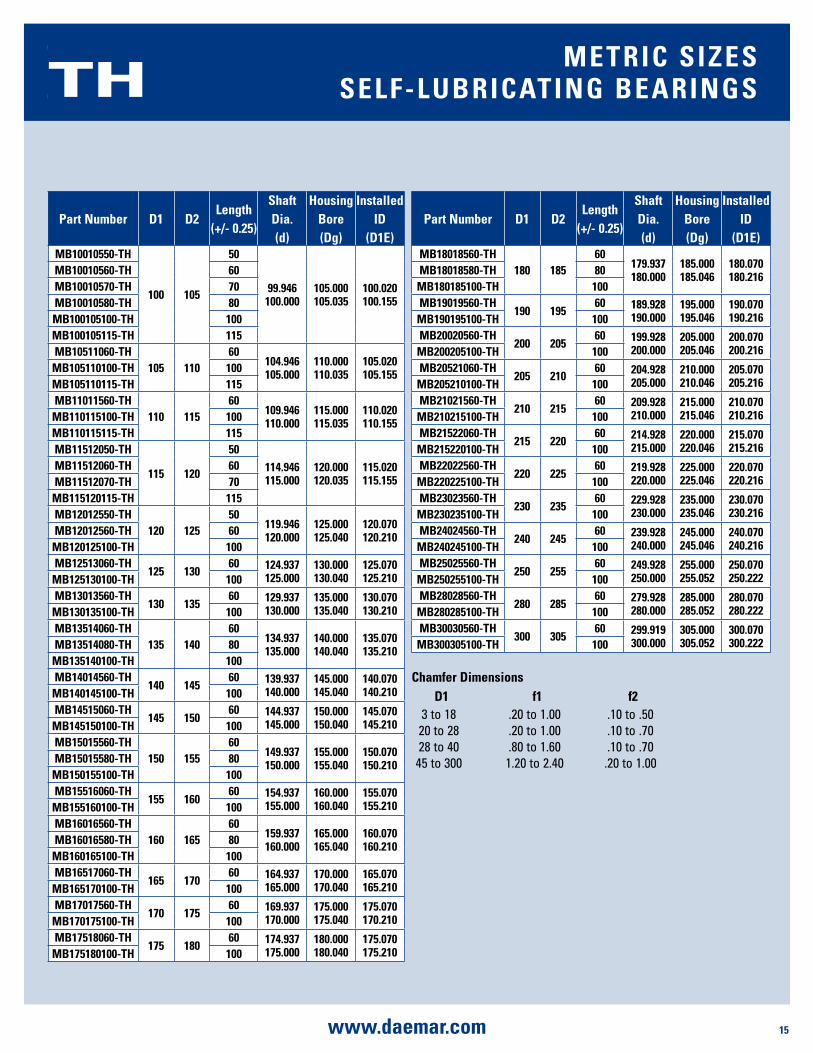
part number d1 d2length
(+/- 0.25)
shaft dia. (d)
housing bore (dg)
installed id
(d1E)mb10010550-Th
100 105
50
99.946100.000
105.000105.035
100.020100.155
mb10010560-Th 60mb10010570-Th 70mb10010580-Th 80mb100105100-Th 100mb100105115-Th 115mb10511060-Th
105 11060
104.946105.000
110.000110.035
105.020105.155mb105110100-Th 100
mb105110115-Th 115mb11011560-Th
110 11560
109.946110.000
115.000115.035
110.020110.155mb110115100-Th 100
mb110115115-Th 115mb11512050-Th
115 120
50114.946115.000
120.000120.035
115.020115.155
mb11512060-Th 60mb11512070-Th 70
mb115120115-Th 115mb12012550-Th
120 12550
119.946120.000
125.000125.040
120.070120.210mb12012560-Th 60
mb120125100-Th 100mb12513060-Th
125 13060 124.937
125.000130.000130.040
125.070125.210mb125130100-Th 100
mb13013560-Th130 135
60 129.937130.000
135.000135.040
130.070130.210mb130135100-Th 100
mb13514060-Th135 140
60134.937135.000
140.000140.040
135.070135.210mb13514080-Th 80
mb135140100-Th 100mb14014560-Th
140 14560 139.937
140.000145.000145.040
140.070140.210mb140145100-Th 100
mb14515060-Th145 150
60 144.937145.000
150.000150.040
145.070145.210mb145150100-Th 100
mb15015560-Th150 155
60149.937150.000
155.000155.040
150.070150.210mb15015580-Th 80
mb150155100-Th 100mb15516060-Th
155 16060 154.937
155.000160.000160.040
155.070155.210mb155160100-Th 100
mb16016560-Th160 165
60159.937160.000
165.000165.040
160.070160.210mb16016580-Th 80
mb160165100-Th 100mb16517060-Th
165 17060 164.937
165.000170.000170.040
165.070165.210mb165170100-Th 100
mb17017560-Th170 175
60 169.937170.000
175.000175.040
175.070170.210mb170175100-Th 100
mb17518060-Th175 180
60 174.937175.000
180.000180.040
175.070175.210mb175180100-Th 100
part number d1 d2length
(+/- 0.25)
shaft dia. (d)
housing bore (dg)
installed id
(d1E)mb18018560-Th
180 18560
179.937180.000
185.000185.046
180.070180.216mb18018580-Th 80
mb180185100-Th 100mb19019560-Th
190 19560 189.928
190.000195.000195.046
190.070190.216mb190195100-Th 100
mb20020560-Th200 205
60 199.928200.000
205.000205.046
200.070200.216mb200205100-Th 100
mb20521060-Th205 210
60 204.928205.000
210.000210.046
205.070205.216mb205210100-Th 100
mb21021560-Th210 215
60 209.928210.000
215.000215.046
210.070210.216mb210215100-Th 100
mb21522060-Th215 220
60 214.928215.000
220.000220.046
215.070215.216mb215220100-Th 100
mb22022560-Th220 225
60 219.928220.000
225.000225.046
220.070220.216mb220225100-Th 100
mb23023560-Th230 235
60 229.928230.000
235.000235.046
230.070230.216mb230235100-Th 100
mb24024560-Th240 245
60 239.928240.000
245.000245.046
240.070240.216mb240245100-Th 100
mb25025560-Th250 255
60 249.928250.000
255.000255.052
250.070250.222mb250255100-Th 100
mb28028560-Th280 285
60 279.928280.000
285.000285.052
280.070280.222mb280285100-Th 100
mb30030560-Th300 305
60 299.919300.000
305.000305.052
300.070300.222mb300305100-Th 100
Chamfer dimensionsd1 f1 f2
3 to 18 .20 to 1.00 .10 to .5020 to 28 .20 to 1.00 .10 to .7028 to 40 .80 to 1.60 .10 to .70
45 to 300 1.20 to 2.40 .20 to 1.00
TH mETRiC sizEssElF-lubRiCaTing bEaRings
16 www.daemar.com
DMR
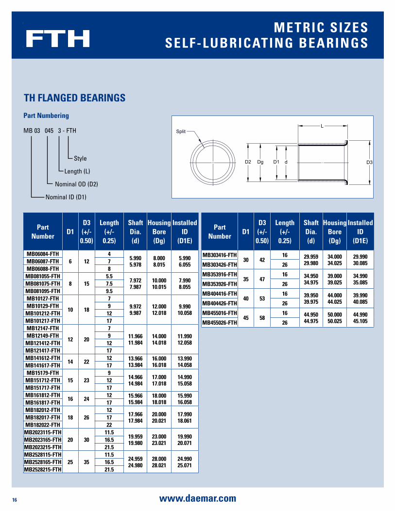
part number
d1d3 (+/- 0.50)
length (+/- 0.25)
shaft dia. (d)
housing bore (dg)
installed id
(d1E)
mb06084-FTh6 12
45.9905.978
8.0008.015
5.9906.055mb06087-FTh 7
mb06088-FTh 8mb081055-FTh
8 155.5
7.9727.987
10.00010.015
7.9908.055mb081075-FTh 7.5
mb081095-FTh 9.5mb10127-FTh
10 18
79.9729.987
12.00012.018
9.99010.058
mb10129-FTh 9mb101212-FTh 12mb101217-FTh 17mb12147-FTh
12 20
711.96611.984
14.00014.018
11.99012.058
mb12149-FTh 9mb121412-FTh 12mb121417-FTh 17mb141612-FTh
14 2212 13.966
13.98416.00016.018
13.99014.058mb141617-FTh 17
mb15179-FTh15 23
914.96614.984
17.00017.018
14.99015.058mb151712-FTh 12
mb151717-FTh 17mb161812-FTh
16 2412 15.966
15.98418.00018.018
15.99016.058mb161817-FTh 17
mb182012-FTh18 26
1217.96617.984
20.00020.021
17.99018.061mb182017-FTh 17
mb182022-FTh 22mb2023115-FTh
20 3011.5
19.95919.980
23.00023.021
19.99020.071mb2023165-FTh 16.5
mb2023215-FTh 21.5mb2528115-FTh
25 3511.5
24.95924.980
28.00028.021
24.99025.071mb2528165-FTh 16.5
mb2528215-FTh 21.5
SplitL
D3dD2 Dg D1
part number
d1d3 (+/- 0.50)
length (+/- 0.25)
shaft dia. (d)
housing bore (dg)
installed id
(d1E)
mb303416-FTh30 42
16 29.95929.980
34.00034.025
29.99030.085mb303426-FTh 26
mb353916-FTh35 47
16 34.95034.975
39.00039.025
34.99035.085mb353926-FTh 26
mb404416-FTh40 53
16 39.95039.975
44.00044.025
39.99040.085mb404426-FTh 26
mb455016-FTh45 58
16 44.95044.975
50.00050.025
44.99045.105mb455026-FTh 26
Th FlangEd bEaRings
FTH mETRiC sizEssElF-lubRiCaTing bEaRings
part numbering
MB 03 045 3 - FTH
Style
Length (L)
Nominal OD (D2)
Nominal ID (D1)
17www.daemar.com
DMR
L
B2
S
part numberd4
(+/- 0.25)d5
(+/- 0.25)s
dowel hole J (+/- 0.12)
a
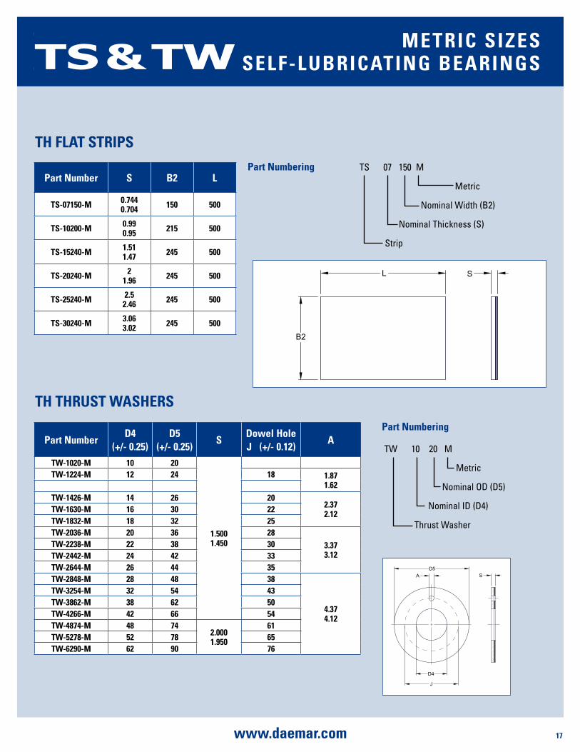
TW-1020-m 10 20
1.5001.450
TW-1224-m 12 24 18 1.871.62
TW-1426-m 14 26 202.372.12TW-1630-m 16 30 22
TW-1832-m 18 32 25TW-2036-m 20 36 28
3.373.12
TW-2238-m 22 38 30TW-2442-m 24 42 33TW-2644-m 26 44 35TW-2848-m 28 48 38
4.374.12
TW-3254-m 32 54 43TW-3862-m 38 62 50TW-4266-m 42 66 54TW-4874-m 48 74
2.0001.950
61TW-5278-m 52 78 65TW-6290-m 62 90 76
part number s b2 l
Ts-07150-m 0.7440.704 150 500
Ts-10200-m 0.990.95 215 500
Ts-15240-m 1.511.47 245 500
Ts-20240-m 21.96 245 500
Ts-25240-m 2.52.46 245 500
Ts-30240-m 3.063.02 245 500
Th ThRusT WashERs
Th FlaT sTRips
D5
D4
J
A S
TS & TW mETRiC sizEssElF-lubRiCaTing bEaRings
TS 07 150 M
Metric
Nominal Width (B2)
Nominal Thickness (S)
Strip
part numbering
part numbering
TW 10 20 M
Metric
Nominal OD (D5)
Nominal ID (D4)
Thrust Washer
18 www.daemar.com
DMR
Split
Dg
D1
d
120 ˚
Lf1
f2
20 ˚`5 ˚
f1
f2D6
45 ˚`5 ˚
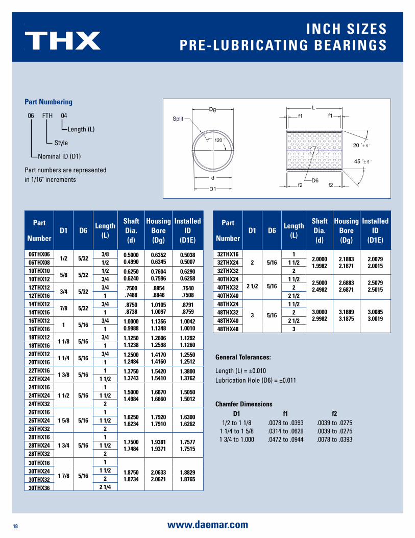
part
numberd1 d6
length (l)
shaft dia. (d)
housing bore (dg)
installed id
(d1E)
06ThX061/2 5/32
3/8 0.50000.4990
0.63520.6345
0.50380.500706ThX08 1/2
10ThX105/8 5/32
1/2 0.62500.6240
0.76040.7596
0.62900.625810ThX12 3/4
12ThX123/4 5/32
3/4 .7500.7488
.8854
.8846.7540.750812ThX16 1
14ThX127/8 5/32
3/4 .8750.8738
1.01051.0097
.8791
.875914ThX16 116ThX12
1 5/163/4 1.0000
0.99881.13561.1348
1.00421.001016ThX16 1
18ThX121 1/8 5/16
3/4 1.12501.1238
1.26061.2598
1.12921.126018ThX16 1
20ThX121 1/4 5/16
3/4 1.25001.2484
1.41701.4160
1.25501.251220ThX16 1
22ThX161 3/8 5/16
1 1.37501.3743
1.54201.5410
1.38001.376222ThX24 1 1/2
24ThX161 1/2 5/16
11.50001.4984
1.66701.6660
1.50501.501224ThX24 1 1/2
24ThX32 226ThX16
1 5/8 5/161
1.62501.6234
1.79201.7910
1.63001.626226ThX24 1 1/2
26ThX32 228ThX16
1 3/4 5/161
1.75001.7484
1.93811.9371
1.75771.751528ThX24 1 1/2
28ThX32 2
30ThX16
1 7/8 5/16
1
1.87501.8734
2.06332.0621
1.88291.8765
30ThX24 1 1/2
30ThX32 2
30ThX36 2 1/4
part
numberd1 d6
length (l)
shaft dia. (d)
housing bore (dg)
installed id
(d1E)
32ThX162 5/16
12.00001.9982
2.18832.1871
2.00792.001532ThX24 1 1/2
32ThX32 240ThX24
2 1/2 5/161 1/2 2.5000
2.49822.68832.6871
2.50792.501540ThX32 2
40ThX40 2 1/248ThX24
3 5/16
1 1/23.00002.9982
3.18893.1875
3.00853.0019
48ThX32 248ThX40 2 1/248ThX48 3
general Tolerances:
Length (L) = ±0.010 Lubrication Hole (D6) = ±0.011
Chamfer dimensionsd1 f1 f2
1/2 to 1 1/8 .0078 to .0393 .0039 to .02751 1/4 to 1 5/8 .0314 to .0629 .0039 to .02751 3/4 to 1.000 .0472 to .0944 .0078 to .0393
THX inCh sizEspRE-lubRiCaTing bEaRings
part numbering
06 FTH 04
Length (L)
Style
Nominal ID (D1)
Part numbers are represented in 1/16" increments
19www.daemar.com
DMR
ThX ThRusT WashERs
J
D5
D4
AS
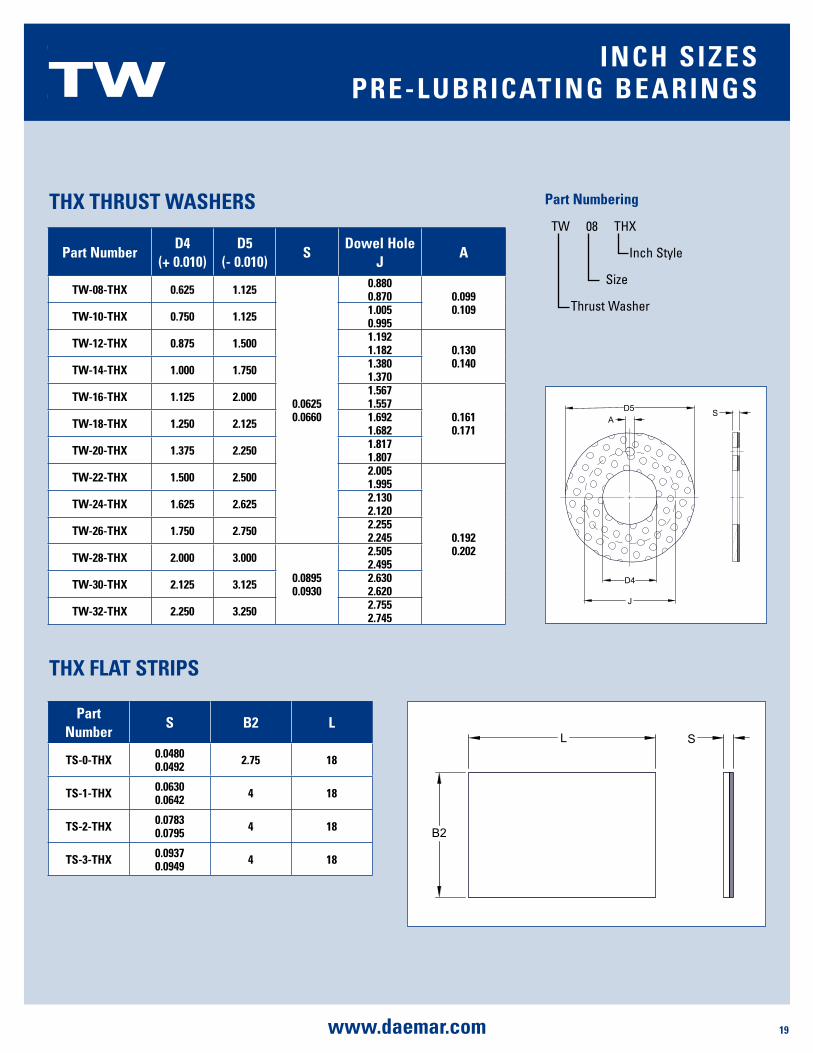
part numberd4
(+ 0.010)d5
(- 0.010)s
dowel hole J
a
TW-08-ThX 0.625 1.125
0.06250.0660
0.8800.870 0.099
0.109TW-10-ThX 0.750 1.125 1.0050.995
TW-12-ThX 0.875 1.500 1.1921.182 0.130
0.140TW-14-ThX 1.000 1.750 1.3801.370
TW-16-ThX 1.125 2.000 1.5671.557
0.1610.171TW-18-ThX 1.250 2.125 1.692
1.682
TW-20-ThX 1.375 2.250 1.8171.807
TW-22-ThX 1.500 2.500 2.0051.995
0.1920.202
TW-24-ThX 1.625 2.625 2.1302.120
TW-26-ThX 1.750 2.750 2.2552.245
TW-28-ThX 2.000 3.000
0.08950.0930
2.5052.495
TW-30-ThX 2.125 3.125 2.6302.620
TW-32-ThX 2.250 3.250 2.7552.745
TW inCh sizEspRE-lubRiCaTing bEaRings
part numbering
TW 08 THX
Inch Style
Size
Thrust Washer
L
B2
S
part number
s b2 l
Ts-0-ThX 0.04800.0492 2.75 18
Ts-1-ThX 0.06300.0642 4 18
Ts-2-ThX 0.07830.0795 4 18
Ts-3-ThX 0.09370.0949 4 18
ThX FlaT sTRips

20 www.daemar.com
DMR
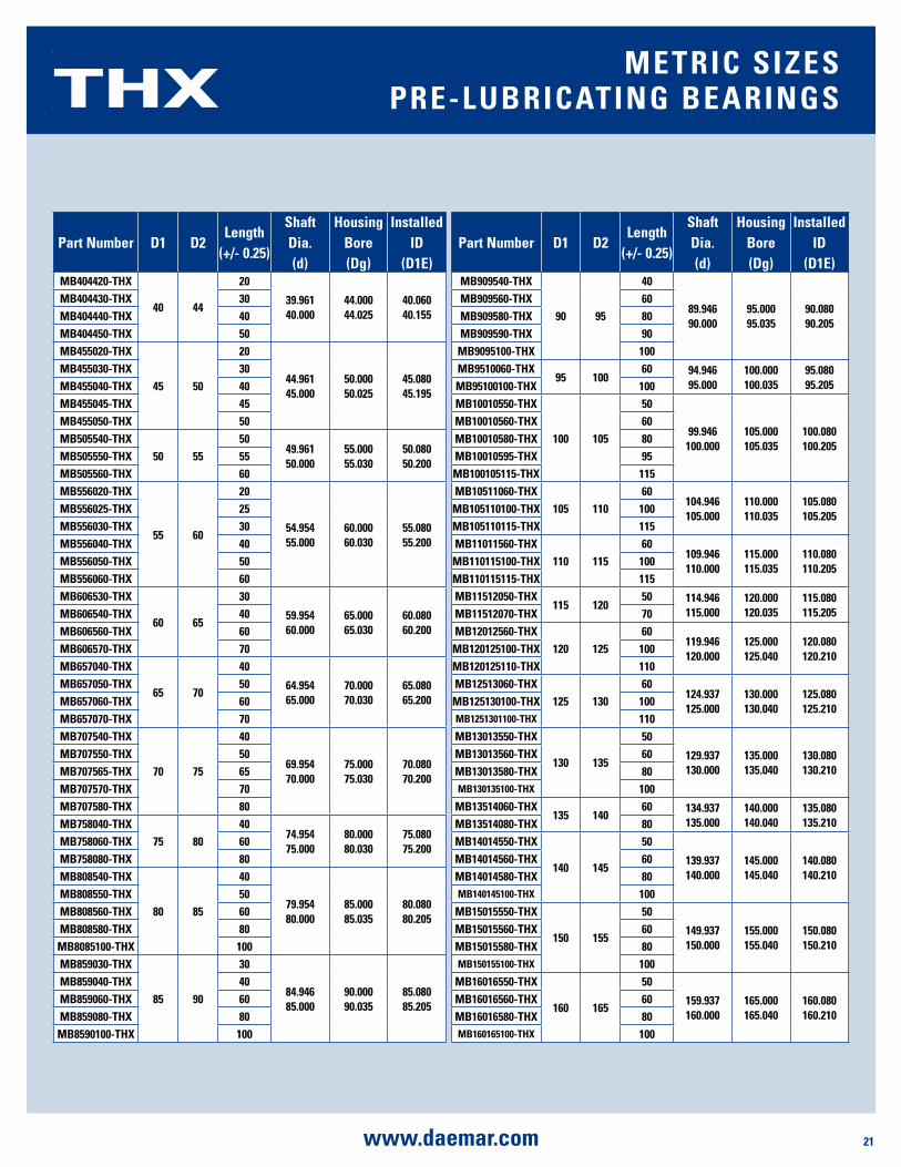
part number d1 d2length
(+/- 0.25)
shaft dia. (d)
housing bore (dg)
installed id
(d1E)mb08108-ThX
8 108
7.9788.000
10.00010.015
8.0408.105
mb081010-ThX 10mb081012-ThX 12mb101210-ThX
10 12
10
9.97810.000
12.00012.018
10.04010.108
mb101212-ThX 12mb101215-ThX 15mb101220-ThX 20mb121410-ThX
12 14
10
11.97312.000
14.00014.018
12.04012.108
mb121412-ThX 12mb121415-ThX 15mb121420-ThX 20mb121425-ThX 25mb141615-ThX
14 1615
13.97314.000
16.00016.018
14.04014.108
mb141620-ThX 20mb141625-ThX 25mb151710-ThX
15 17
10
14.97315.000
17.00017.018
15.04015.108
mb151712-ThX 12mb151715-ThX 15mb151720-ThX 20mb161815-ThX
16 1815
15.97316.000
18.00018.018
16.04016.108
mb161820-ThX 20mb161825-ThX 25mb182015-ThX
18 2015
17.97318.000
20.00020.021
18.04018.111
mb182020-ThX 20mb182025-ThX 25mb202310-ThX
20 23
10
19.96720.000
23.00023.021
20.05020.131
mb202315-ThX 15mb202320-ThX 20mb202325-ThX 25mb202330-ThX 30
part number d1 d2length
(+/- 0.25)
shaft dia. (d)
housing bore (dg)
installed id
(d1E)mb222515-ThX
22 25
15
21.96722.000
25.00025.021
22.05022.131
mb222520-ThX 20mb222525-ThX 25mb222530-ThX 30mb242715-ThX
24 27
15
23.96724.000
27.00027.021
24.05024.131
mb242720-ThX 20mb242725-ThX 25mb242730-ThX 30mb252815-ThX
25 28
15
24.96725.000
28.00028.021
25.05025.131
mb252820-ThX 20mb252825-ThX 25mb252830-ThX 30
mb283130-ThX 28 31 3027.96728.000
31.00031.025
28.05028.135
mb283220-ThX28 32
2027.96728.000
32.00032.025
28.06028.155
mb283225-ThX 25mb283230-ThX 30mb303420-ThX
30 3420
29.96730.000
34.00034.025
30.06030.155
mb303430-ThX 30mb303440-ThX 40mb323620-ThX
32 36
20
31.96132.000
36.00036.025
32.06032.155
mb323630-ThX 30mb323635-ThX 35mb323640-ThX 40mb353920-ThX
35 39
20
34.96135.000
39.00039.025
35.06035.155
mb353930-ThX 30mb353935-ThX 35mb353940-ThX 40
mb364035-ThX 36 40 3535.96136.000
40.00040.025
36.06036.155
mb374120-ThX 37 41 2036.96137.000
41.00041.025
37.06037.155
part numbering
MB 08 10 08 THX
Style
Length (L)
Nominal OD (D2)
Nominal ID (D1)
THX mETRiC sizEspRE-lubRiCaTing bEaRings
Split
Dg
D1
d
120 ˚
Lf1
f2
20 ˚`5 ˚
f1
f2D6
45 ˚`5 ˚
21www.daemar.com
DMR
part number d1 d2length
(+/- 0.25)
shaft dia. (d)
housing bore (dg)
installed id
(d1E)mb404420-ThX
40 44
20
39.96140.000
44.00044.025
40.06040.155
mb404430-ThX 30mb404440-ThX 40mb404450-ThX 50mb455020-ThX
45 50
20
44.96145.000
50.00050.025
45.08045.195
mb455030-ThX 30mb455040-ThX 40mb455045-ThX 45mb455050-ThX 50mb505540-ThX
50 5550
49.96150.000
55.00055.030
50.08050.200
mb505550-ThX 55mb505560-ThX 60mb556020-ThX
55 60
20
54.95455.000
60.00060.030
55.08055.200
mb556025-ThX 25mb556030-ThX 30mb556040-ThX 40mb556050-ThX 50mb556060-ThX 60mb606530-ThX
60 65
30
59.95460.000
65.00065.030
60.08060.200
mb606540-ThX 40mb606560-ThX 60mb606570-ThX 70mb657040-ThX
65 70
40
64.95465.000
70.00070.030
65.08065.200
mb657050-ThX 50mb657060-ThX 60mb657070-ThX 70mb707540-ThX
70 75
40
69.95470.000
75.00075.030
70.08070.200
mb707550-ThX 50mb707565-ThX 65mb707570-ThX 70mb707580-ThX 80mb758040-ThX
75 8040
74.95475.000
80.00080.030
75.08075.200
mb758060-ThX 60mb758080-ThX 80mb808540-ThX
80 85
40
79.95480.000
85.00085.035
80.08080.205
mb808550-ThX 50mb808560-ThX 60mb808580-ThX 80
mb8085100-ThX 100mb859030-ThX
85 90
30
84.94685.000
90.00090.035
85.08085.205
mb859040-ThX 40mb859060-ThX 60mb859080-ThX 80
mb8590100-ThX 100
part number d1 d2length
(+/- 0.25)
shaft dia. (d)
housing bore (dg)
installed id
(d1E)mb909540-ThX
90 95
40
89.94690.000
95.00095.035
90.08090.205
mb909560-ThX 60mb909580-ThX 80mb909590-ThX 90
mb9095100-ThX 100mb9510060-ThX
95 10060 94.946
95.000100.000100.035
95.08095.205mb95100100-ThX 100
mb10010550-ThX
100 105
50
99.946100.000
105.000105.035
100.080100.205
mb10010560-ThX 60mb10010580-ThX 80mb10010595-ThX 95mb100105115-ThX 115mb10511060-ThX
105 11060
104.946105.000
110.000110.035
105.080105.205
mb105110100-ThX 100mb105110115-ThX 115mb11011560-ThX
110 11560
109.946110.000
115.000115.035
110.080110.205
mb110115100-ThX 100mb110115115-ThX 115mb11512050-ThX
115 12050 114.946
115.000120.000120.035
115.080115.205mb11512070-ThX 70
mb12012560-ThX120 125
60119.946120.000
125.000125.040
120.080120.210
mb120125100-ThX 100mb120125110-ThX 110mb12513060-ThX
125 13060
124.937125.000
130.000130.040
125.080125.210
mb125130100-ThX 100mb1251301100-ThX 110mb13013550-ThX
130 135
50
129.937130.000
135.000135.040
130.080130.210
mb13013560-ThX 60mb13013580-ThX 80mb130135100-ThX 100
mb13514060-ThX135 140
60 134.937135.000
140.000140.040
135.080135.210mb13514080-ThX 80
mb14014550-ThX
140 145
50
139.937140.000
145.000145.040
140.080140.210
mb14014560-ThX 60mb14014580-ThX 80mb140145100-ThX 100
mb15015550-ThX
150 155
50
149.937150.000
155.000155.040
150.080150.210
mb15015560-ThX 60mb15015580-ThX 80mb150155100-ThX 100
mb16016550-ThX
160 165
50
159.937160.000
165.000165.040
160.080160.210
mb16016560-ThX 60mb16016580-ThX 80mb160165100-ThX 100
THX mETRiC sizEspRE-lubRiCaTing bEaRings

22 www.daemar.com
DMR
part number d1 d2length
(+/- 0.25)
shaft dia. (d)
housing bore (dg)
installed id
(d1E)mb17017550-ThX
170 175
50
169.937170.000
175.000175.040
170.080170.210
mb17017560-ThX 60
mb17017580-ThX 80
mb170175100-ThX 100
mb18018550-ThX
180 185
50
179.937180.000
185.000185.046
180.080180.216
mb18018560-ThX 60
mb18018580-ThX 80
mb180185100-ThX 100
mb19019550-ThX
190 195
50
189.928190.000
195.000195.046
190.080190.216
mb19019560-ThX 60
mb19019580-ThX 80
mb190195100-ThX 100
mb190195120-ThX 120
mb20020550-ThX
200 205
50
199.928200.000
205.000205.046
200.080200.216
mb20020560-ThX 60
mb20020580-ThX 80
mb200205100-ThX 100
mb200205120-ThX 120
mb22022550-ThX
220 225
50
219.928220.000
225.000225.046
220.080220.216
mb22022560-ThX 60
mb22022580-ThX 80
mb220225100-ThX 100
mb220225120-ThX 120
mb24024550-ThX
240 245
50
239.928240.000
245.000245.046
240.080240.216
mb24024560-ThX 60
mb24024580-ThX 80
mb240245100-ThX 100
mb240245120-ThX 120
mb25025550-ThX
250 255
50
249.928250.000
255.000255.052
250.080250.222
mb25025560-ThX 60
mb25025580-ThX 80
mb250255100-ThX 100
mb250255120-ThX 120
mb26026550-ThX
260 265
50
259.919260.000
265.000265.052
260.080260.222
mb26026560-ThX 60
mb26026580-ThX 80
mb260265100-ThX 100
mb260265120-ThX 120
mb28028550-ThX
280 285
50
279.919280.000
285.000285.052
280.080280.222
mb28028560-ThX 60
mb28028580-ThX 80
mb280285100-ThX 100
mb280285120-ThX 120
part number d1 d2length
(+/- 0.25)
shaft dia. (d)
housing bore (dg)
installed id
(d1E)mb30030550-ThX
300 305
50
299.919300.000
305.000305.052
300.080300.222
mb30030560-ThX 60
mb30030580-ThX 80
mb300305100-ThX 100
mb300305120-ThX 120
Chamfer dimensionsd1 f1 f2
8 to 18 .20 to 1.00 .10 to .5020 to 28 .20 to 1.00 .10 to .7028 to 40 .80 to 1.60 .10 to .70
45 to 300 1.20 to 2.40 .20 to 1.00
Oil hole diameter (d6)d1 d6 (mm) tolerance8 no hole
10 to 22 3 ±0.3024 to 40 4 ±0.3045 to 50 5 ±0.30
55 to 100 6 ±0.30105 to 300 8 ±0.30
THX mETRiC sizEspRE-lubRiCaTing bEaRings
23www.daemar.com
DMR
L
B2
S
part numberd4
(+/- 0.25)d5
(+/- 0.25)s
dowel hole J (+/- 0.12)
a
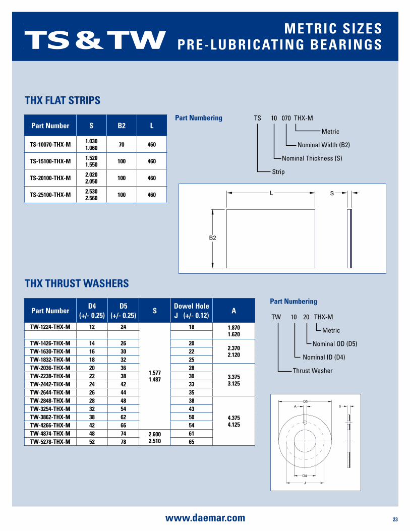
TW-1224-ThX-m 12 24
1.5771.487
18 1.8701.620
TW-1426-ThX-m 14 26 202.3702.120TW-1630-ThX-m 16 30 22
TW-1832-ThX-m 18 32 25TW-2036-ThX-m 20 36 28
3.3753.125
TW-2238-ThX-m 22 38 30TW-2442-ThX-m 24 42 33TW-2644-ThX-m 26 44 35TW-2848-ThX-m 28 48 38
4.3754.125
TW-3254-ThX-m 32 54 43TW-3862-ThX-m 38 62 50TW-4266-ThX-m 42 66 54TW-4874-ThX-m 48 74 2.600
2.51061
TW-5278-ThX-m 52 78 65
part number s b2 l
Ts-10070-ThX-m 1.0301.060 70 460
Ts-15100-ThX-m 1.5201.550 100 460
Ts-20100-ThX-m 2.0202.050 100 460
Ts-25100-ThX-m 2.5302.560 100 460
ThX ThRusT WashERs
ThX FlaT sTRips
D5
D4
J
A S
TS & TW mETRiC sizEspRE-lubRiCaTing bEaRings
TS 10 070 THX-M
Metric
Nominal Width (B2)
Nominal Thickness (S)
Strip
part numbering
part numbering
TW 10 20 THX-M
Metric
Nominal OD (D5)
Nominal ID (D4)
Thrust Washer

24 www.daemar.com
DMR
ChEmiCal pROpERTiEs The PTFE sliding layer is resistant to most chemical products, while the corrosion resistance of TH bushing depends on the steel backing which does not oxidize when:
• Immersed in water, alcohols or glycols • In the presence of mineral and synthetic oils • In acid substances with a pH level of > 5 • In alkali substances with a pH level of < 9
Corrosion is triggered off in the case of repeated wet/dry cycles, the presence of oxygen and when the temperature exceeds 90ºC.
The chemical resistance of TH bushing is improved by tin-plating, but the problems of corrosion must be overcome by further protection such as special tin-plating, by sealing the bearings or by using the bronze-backed bearings (TH-B) or stainless steel-backed bearings (TH30).
ThERmal COnduCTiViTyDuring operation heat is generated by the friction between the bearing and the shaft. The heat is partly dissipated by the fluids present (gas or liquids) and partly absorbed by the mating parts.
Under normal operating conditions, the bearing must be able to dissipate the heat generated and not give rise to thermal dilations that may compromise the working of the two parts. Under both aspects, TH bushing performs very well as it features:
Perpendicular thermal conductivity which is linked to the steel backing and the close contact of the bronze and the polymer layer. Both factors lead to a high level of thermal conductivity between the layers that enables the heat to be eliminated without causing a sharp rise in the temperature (on average + 20º to 25ºC compared to the temperature of the environment).
Volumetric expansion: the increase in temperature gives rise to an expansion in the volume of the materials. Given the composition of the product, TH bushing expands in a way very similar to that of metals normally used for the housing and the counterpart. This similar behaviour prevents seizure during
heating and movement of the bearing in the housing during cooling which sometimes arises when plastic bearings are used.
ElECTRiCal COnduCTiViTyTH bushing not only offers a high level of thermal conductivity, but also a high level of electrical conductivity that is perpendicular to the layers. However, this electrical conductivity only appears after the first running-in period, when the bronze starts to be exposed and comes into contact with the mating surface. The perpendicular electrical conductivity increases with the specific load applied on the bearing and with the degree of wear. Typical values of specific electrical resistance for units-surface are the following:
Perpendicular electrical resistance: R = 1 - 10W x cm2
FRiCTiOnThe TH bushing sliding layer has a PTFE base that gives an excellent slide quality due to the low coefficient of friction. The amount of friction cannot be defined exactly as it is influenced by the following parameters:
• Load factor p x v on the surface • Operating temperature • Presence of liquids and lubricants • Material and finish of the mating surface
The load factor p x v is the result of the specific load p (N/mm2) and the speed v (m/s) and represents the reference parameter for checking the performance of this type of bearing. p x v being equal, the coefficient of friction decreases as the specific load increases, while the coefficient of friction increases as the speed increases.
sliding speed v (m/s)
specific load p (n/mm2)
Coefficient of Friction μ
up to 0.001 140 0.03
0.001 to 0.005 140 to 62 0.04 to 0.07
0.005 to 0.05 62 to 11 0.07 to 0.1
0.05 to 0.5 11 to 1 0.1 to 0.15
0.5 to 2 1 0.15 to 0.20
dEsign nOTEs
25www.daemar.com
DMR
TEmpERaTuREThe temperature has a very slight effect on the coefficient of friction if it remains within a range of 0º to 100ºC. Once these limits are exceeded, the coefficient of friction increases rapidly by 50% or more. It should be noted that very high temperatures reduce the useful life of TH bearings. Under equal load factors, the useful life is reduced by 80% at a temperature of over 200ºC compared to that noted at 25ºC.
liquids and lubRiCanTsTH bearings have been designed for dry operations, but despite this, the presence of clean fluids in the working area can facilitate the dissipation of heat and prolong the useful life of the bearing.
The presence of liquids, whether lubricants or other, may lead to hydrodynamic operating conditions which enable a considerable increase in the sliding speed at the same specific load. Hydrodynamic operating conditions are influenced by the following parameters:
• Sliding speed • Specific load • Tolerance of the mating surfaces • Viscosity of the liquid • Operating temperature
OpERaTiOn in ThE pREsEnCE OF liquids and lubRiCanTsIn practise, even the self-lubricated bearings (TH Series) can be used in the presence of liquids and/or lubricating fluids.
In these situations, the behaviour of the bearings are modified and the following considerations apply:
• The presence of a clean fluid on the bearing (whether lubricating or not) usually has a positive effect as it improves the dissipation of the heat caused by the friction and also improves the contact between the sliding surfaces.
• It is necessary to the check the compatibility of the bearing with the fluid. Most problems arise with THX bearings as the acetal co-polymer is not recommended for use in water, glycols or synthetic oils with phosphoric esters. The other TH Series does not have any particular contraindications in the presence of widely used liquids and lubricants.
If in doubt and in case of special applications, it is advisable to carry out a simple test by immersing half of a sample bearing in the liquid in question. If, after two weeks, the bearing shows non signs of alteration in any part it can be considered to be compatible with the fluid.
• For the TH Series of bearings, the positive effects of the presence of fluids are confirmed only if alternating dry and wet cycles are avoided. In the presence of repeated cycles, the result is a premature decline in the product compared to dry operating conditions.
• For the bearings subject to lubrication, just the initial greasing may be sufficient as long as the application is subject to limited specific load and speed values.
lubRiCaTiOn sysTEmsIn the presence of fluids and under certain speed and specific load conditions, hydrodynamic lubrication occurs. This involves a thin film of fluid being generated permanently between the mating surfaces. During a hydrodynamic regime, the coefficient of friction and the wear of the parts falls to such a level that the life of the bearing depends more on the number of stop-start operations rather than the actual running time.
If a hydrodynamic operating regime is provided for during the design phase, steps must be taken to increase the clearance of the mating parts to facilitate the formation and maintenance of the separating film.
maTERial and Finish OF ThE maTing suRFaCEThe material of the mating surface, whether it is a shaft or a shoulder, has a considerable effect on the results of the application. The metals which may corrode in the presence of humidity or pollutants, accelerate the deterioration of the mating surface.
For applications with no protection, it is advisable to use stainless steel, chromium-plated steel or anodized aluminum mating surfaces.
Bronze, non-anodized aluminum, phosphated or nickel-plated steel mating surfaces are not suitable. The roughness of the mating surface must be quite low to permit a good operating life. The recommended value for the best performance is 0.4mm Ra.
dEsign nOTEs
26 www.daemar.com
DMR
Thrust Washer
specific bearing load (n/mm2)
sliding speed (m/s) Rotation
sliding speed (m/s) Oscillation
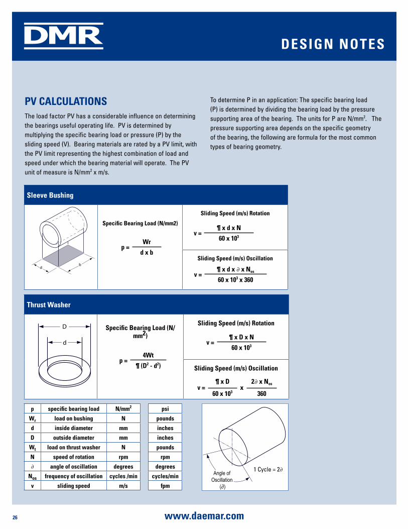
pV CalCulaTiOnsThe load factor PV has a considerable influence on determining the bearings useful operating life. PV is determined by multiplying the specific bearing load or pressure (P) by the sliding speed (V). Bearing materials are rated by a PV limit, with the PV limit representing the highest combination of load and speed under which the bearing material will operate. The PV unit of measure is N/mm2 x m/s.
To determine P in an application: The specific bearing load (P) is determined by dividing the bearing load by the pressure supporting area of the bearing. The units for P are N/mm2. The pressure supporting area depends on the specific geometry of the bearing, the following are formula for the most common types of bearing geometry.
p =4Wt
¶ (d2 - d2)
v =¶ x d x n
60 x 103
v =¶ x d
x2∂ x nos
60 x 103 360
p specific bearing load n/mm2 psi
Wr load on bushing n pounds
d inside diameter mm inches
d outside diameter mm inches
Wt load on thrust washer n pounds
n speed of rotation rpm rpm
∂ angle of oscillation degrees degrees
nos frequency of oscillation cycles /min cycles/min
v sliding speed m/s fpm
Angle of Oscillation
(∂)
1 Cycle = 2∂
dEsign nOTEs
sleeve bushing
specific bearing load (n/mm2)
sliding speed (m/s) Rotation
sliding speed (m/s) Oscillation
p =Wr
d x b
v =¶ x d x n
60 x 103
v =¶ x d x ∂ x nos
60 x 103 x 360
db
D
d
27www.daemar.com
DMR
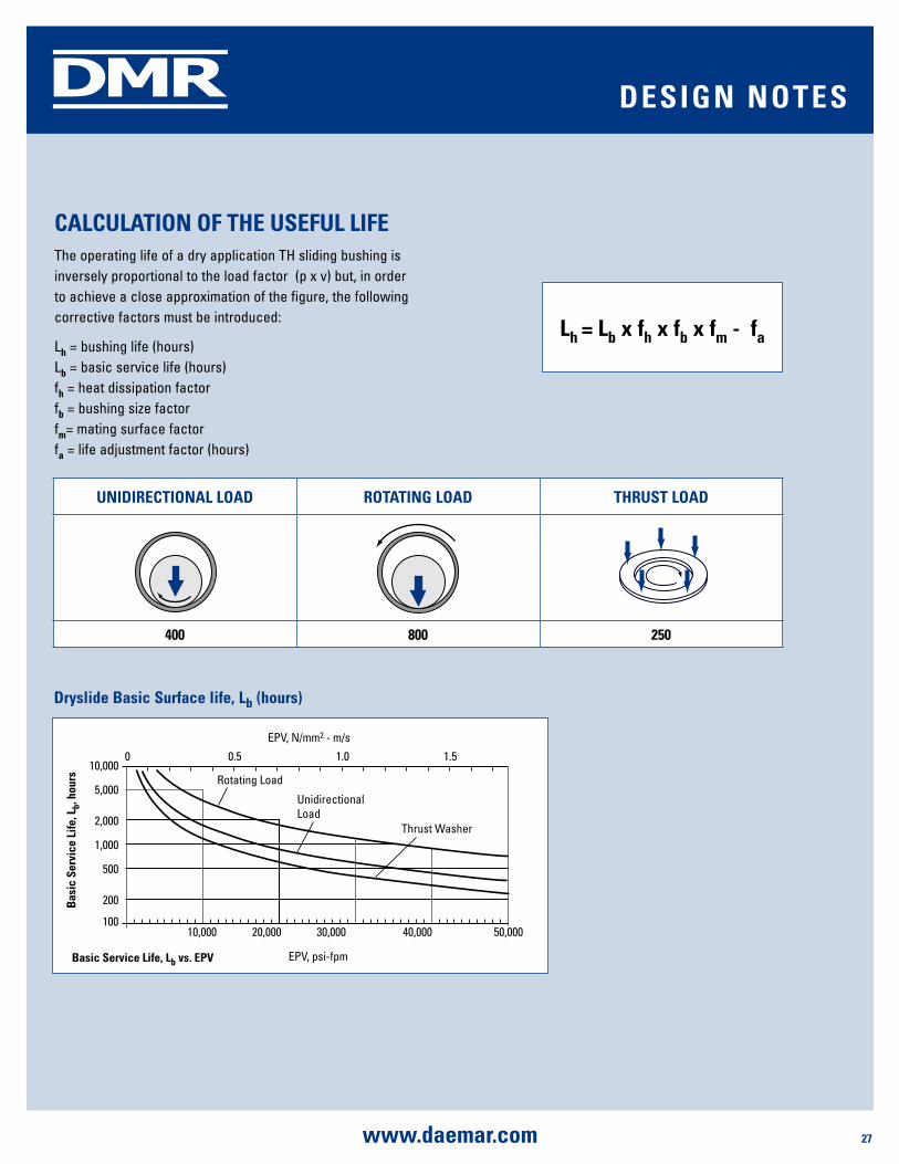
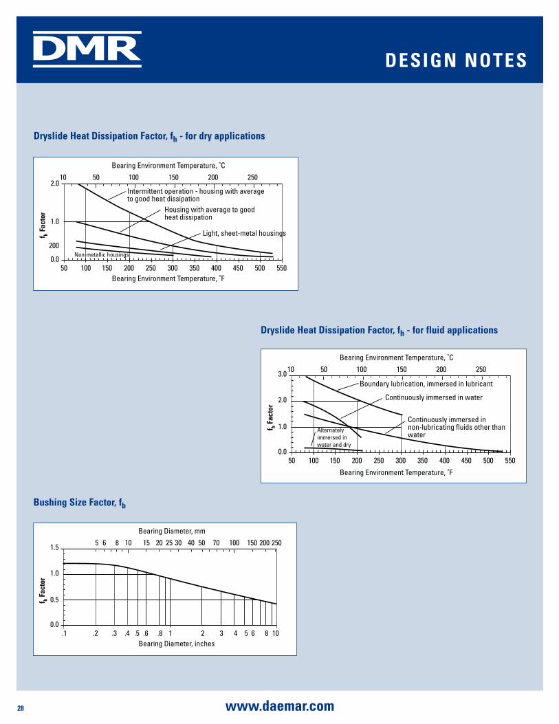
CalCulaTiOn OF ThE usEFul liFEThe operating life of a dry application TH sliding bushing is inversely proportional to the load factor (p x v) but, in order to achieve a close approximation of the figure, the following corrective factors must be introduced:
Lh = bushing life (hours)Lb = basic service life (hours) fh = heat dissipation factor fb = bushing size factorfm= mating surface factorfa = life adjustment factor (hours)
unidiRECTiOnal lOad ROTaTing lOad ThRusT lOad
400 800 250
dEsign nOTEs
lh = lb x fh x fb x fm - fa
Basic Service Life, Lb vs. EPV EPV, psi-fpm
Thrust Washer
Unidirectional Load
Rotating Load
EPV, N/mm2 - m/s
Bas
ic S
ervi
ce L
ife, L
b, h
ours
10,000
5,000
2,000
1,000
500
200
10010,000 20,000 30,000 40,000 50,000
0 0.5 1.0 1.5
dryslide basic surface life, lb (hours)
28 www.daemar.com
DMR dEsign nOTEs
dryslide heat dissipation Factor, fh - for dry applications
Bearing Environment Temperature, ˚F
Light, sheet-metal housings
Housing with average to good heat dissipation
Intermittent operation - housing with average to good heat dissipation
Bearing Environment Temperature, ˚C
f h Fac
tor
2.0
1.0
200
0.050 100 150 200 250 300 350 400 450 500 550
10 50 100 150 250200
Non-metallic housings
dryslide heat dissipation Factor, fh - for fluid applications
Bearing Environment Temperature, ˚F
Continuously immersed in non-lubricating fluids other than water
Continuously immersed in water
Boundary lubrication, immersed in lubricant
Bearing Environment Temperature, ˚C
f h Fac
tor
3.0
1.0
2.0
0.050 100 150 200 250 300 350 400 450 500 550
10 50 100 150 250200
Alternately immersed in water and dry
bushing size Factor, fb
Bearing Diameter, inches
Bearing Diameter, mm
f b Fac
tor
1.5
0.5
1.0
0.0.1 .2 .3 .4 .5 .6 .8 1 2 3 4 5 6 8 10
5 6 8 10 15 20 25 30 40 50 25070 100 150 200
29www.daemar.com
DMR
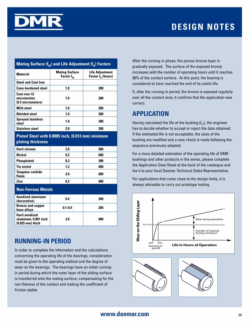
Running-in pERiOdIn order to complete the information and the calculations concerning the operating life of the bearings, consideration must be given to the operating method and the degree of wear on the bearings. The bearings have an initial running-in period during which the outer layer of the sliding surface is transferred onto the mating surface, compensating for the non-flatness of the contact and making the coefficient of friction stable.
After the running-in phase, the porous bronze layer is gradually exposed. The surface of the exposed bronze increases with the number of operating hours until it reaches 90% of the contact surface. At this point, the bearing is considered to have reached the end of its useful life.
If, after the running-in period, the bronze is exposed regularly over all the contact area, it confirms that the application was correct.
appliCaTiOnHaving calculated the life of the bushing (Lh), the engineer has to decide whether to accept or reject the data obtained. If the estimated life is not acceptable, the sizes of the bushing are modified and a new check is made following the sequence previously adopted.
For a more detailed estimation of the operating life of DMR bushings and other products in the series, please complete the Application Data Sheet at the back of the catalogue and fax it to your local Daemar Technical Sales Representative.
For applications that come close to the design limits, it is always advisable to carry out prototype testing.
Wea
r on
the
Slid
ing
Laye
r
Life in Hours of Operation
Wear during operation
Transfer of materialduring running-in
Running-inperiod
0.01 mm
dEsign nOTEs
mating surface (fm) and life adjustment (fa) Factors
material mating surface Factor fm
life adjustment Factor fa (hours)
steel and Cast iron
Case-hardened steel 1.0 200
Cast iron-12 microinches (0.3 micrometers)
1.0 200
mild steel 1.0 200
nitrided steel 1.0 200sprayed stainless steel 1.0 200
stainless steel 2.0 200
plated steel with 0.0005 inch, (0.013 mm) minimum plating thickness
hard chrome 2.0 600
nickel 0.2 600
phosphated 0.2 300
Tin nickel 1.2 600Tungsten carbide flame 3.0 600
zinc 0.2 600
non-Ferrous metals
anodized aluminum (decorative) 0.4 200
bronze and copper base alloys 0.1-0.4 200
hard anodized aluminum, 0.001 inch (0.025 mm) thick
3.0 600

30 www.daemar.com
DMR
FiTTing mEThOdsThe most commonly used method for fitting the bushings is to press them into the housing. Having created the correct housing (H7), the following steps should be taken:
• Chamfer the lead-in to the housing by 20° ± 5° to a depth of 1-2mm
• Deburr and clean the mating surfaces• Lubricate the outside surface of the bushing before fitting it
(do not apply excessive lubricant as it may cause the bushing to move about when fitted in the housing)
• Check the alignment of the axes between the bushing and the housing
• Where several bushings are necessary, align the butt joints• It is always advisable to use a guiding mandrel to insert the
bushings in their housing
Press fitting is usually carried out using hydraulic, pneumatic or mechanical equipment (fig 1).
To fit bushings with a diameter or more than 55mm, it is advisable to use a retaining ring with a diameter that is 0.3/0.4mm larger (fig. 2)
For flange bushings (fig. 3), the chamfer on the lead-in must have an angle of 45º and a depth of at least 2mm (2.55 for a bushing with a wall thickness of 2.5mm).
approximate Values of the pressing Force "F" in newtons
bushing Thickness 1 mm F = 300 x l
bushing Thickness 1.5 mm F = 500 x l
bushing Thickness 2 mm F = 700 x l
bushing Thickness 2.5 mm F = 900 x l
F
Oil
Fig. 1
> 55
F
Oil
Fig. 2
A
A
0.5 x 15_
2 x 45_
F
Fig. 3
insTallaTiOn guidE
31www.daemar.com
DMR
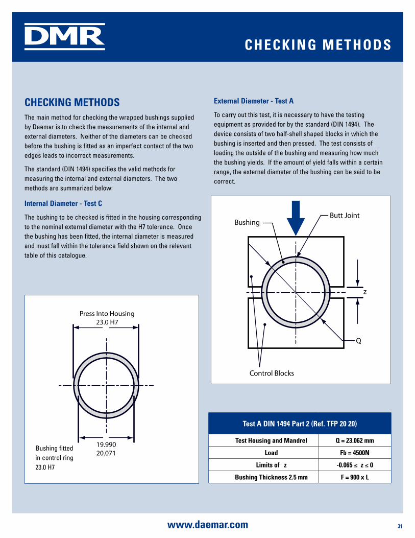
ChECKing mEThOdsThe main method for checking the wrapped bushings supplied by Daemar is to check the measurements of the internal and external diameters. Neither of the diameters can be checked before the bushing is fitted as an imperfect contact of the two edges leads to incorrect measurements.
The standard (DIN 1494) specifies the valid methods for measuring the internal and external diameters. The two methods are summarized below:
internal diameter - Test C
The bushing to be checked is fitted in the housing corresponding to the nominal external diameter with the H7 tolerance. Once the bushing has been fitted, the internal diameter is measured and must fall within the tolerance field shown on the relevant table of this catalogue.
External diameter - Test a
To carry out this test, it is necessary to have the testing equipment as provided for by the standard (DIN 1494). The device consists of two half-shell shaped blocks in which the bushing is inserted and then pressed. The test consists of loading the outside of the bushing and measuring how much the bushing yields. If the amount of yield falls within a certain range, the external diameter of the bushing can be said to be correct.
Test a din 1494 part 2 (Ref. TFp 20 20)
Test housing and mandrel q = 23.062 mm
load Fb = 4500n
limits of Δz -0.065 ≤ Δz ≤ 0
bushing Thickness 2.5 mm F = 900 x l
ChECKing mEThOds
Press Into Housing23.0 H7
19.99020.071
Bushing fitted in control ring 23.0 H7
Control Blocks
Butt JointBushing
z
Q

32 www.daemar.com
DMR
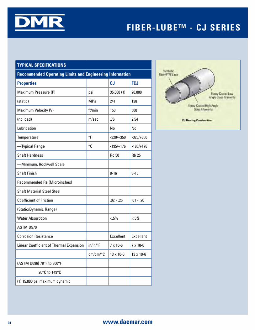
CJ composites are ideal for non-lubricated, high-load applications in a variety of climates and operating environments, exhibit a high load capacity similar to bronze, powdered metal and steel, and provide longer wear and extended operating life without the costs associated with lubrication. CJ composites are available with thick walls for drop in replacement of steel and bronze bearings. CJ composites also don’t rust like metal components, so you can use them in environments where traditional metals corrode and fail. You’ll find CJ bearing materials in heavy-duty agricultural, automotive, construction, industrial, marine, railway, and material handling equipment.
CJ composites possess a modulus of elasticity that falls between rigid metals and soft plastics. CJ components are rigid enough to support heavy loads, yet compliant enough to tolerate moderate amounts of shaft misalignment without highly stressing the ends. The composite wall acts like a spring and the thicker the wall section of the bearing the greater the deflection for a given load. Thick wall bearings tolerate greater shaft misalignment and provide better shock absorbency.
FibER-lubE™ - CJ sERiEs
FEaTuREs bEnEFiTs
High-load capacity/ high-shock load capability Accommodates tremendous compression loads that literally crush competing composite materials.
Self-lubricating design Provides maintenance-free operation and eliminates the need for costly and messy greasing systems.
Low coefficient of friction Reduces wear and extends operating life. Coefficients as low as 0.05 in dry applications and <0.009 in lubricated environments.
Temperature resistant Operates flawlessly in temperatures ranging from cryogenic levels to a high of 300°F (149°C). Call for higher temperature availability.
Dimensionally stable in fluids (water, corrosive liquids, and chemical solutions)
Absorption rates are negligible, providing near zero swell.
Chemical resistant Compatible with a wide range of lubricants and media.
Flexible material design Suitable for press fit, freeze fit, epoxy bonding, as well as conventional mechanical retention.
Low weight/high strength Accommodates high-load with a compact strength to weight ratio.
Thick-wall availability Drop in replacement for metal or bronze bearings

33www.daemar.com
DMR FibER-lubE™ - CJ sERiEs
CJ applications FCJ applications• Back hoes • Material handling equipment
• Front end loaders • Packaging machinery
• Marine Davits/Sheaves • Farm implements
• Valve stem bushings • Spreaders
• Hitches • Marine pivots
• Hydraulic cylinder pivots • Robotics
• Graders • Business machines
• Mining equipment • Linear bearings
• Vending machines • Amusement park rides
34 www.daemar.com
DMR FibER-lubE™ - CJ sERiEs
TypiCal spECiFiCaTiOns
Recommended Operating limits and Engineering information
properties CJ FCJ
Maximum Pressure (P) psi 35,000 (1) 20,000
(static) MPa 241 138
Maximum Velocity (V) ft/min 150 500
(no load) m/sec .76 2.54
Lubrication No No
Temperature °F -320/+350 -320/+350
—Typical Range °C -195/+176 -195/+176
Shaft Hardness Rc 50 Rb 25
—Minimum, Rockwell Scale
Shaft Finish 8-16 8-16
Recommended Ra (Microinches)
Shaft Material Steel Steel
Coefficient of Friction .02 - .25 .01 - .20
(Static/Dynamic Range)
Water Absorption <.5% <.5%
ASTM D570
Corrosion Resistance Excellent Excellent
Linear Coefficient of Thermal Expansion in/in/°F 7 x 10⁻⁶ 7 x 10⁻⁶
cm/cm/°C 13 x 10-6 13 x 10-6
(ASTM D696) 78°F to 300°F
26°C to 149°C
(1) 15,000 psi maximum dynamic
35www.daemar.com
DMR FibER-lubE™ - CJ sERiEs
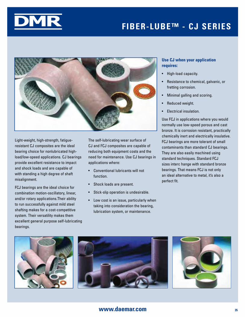
Light-weight, high-strength, fatigue-resistant CJ composites are the ideal bearing choice for nonlubricated high-load/low-speed applications. CJ bearings provide excellent resistance to impact and shock loads and are capable of with standing a high degree of shaft misalignment.
FCJ bearings are the ideal choice for combination motion-oscillatory, linear, and/or rotary applications.Their ability to run successfully against mild steel shafting makes for a cost-competitive system. Their versatility makes them excellent general purpose self-lubricating bearings.
The self-lubricating wear surface of CJ and FCJ composites are capable of reducing both equipment costs and the need for maintenance. Use CJ bearings in applications where:
• Conventional lubricants will not function.
• Shock loads are present.
• Stick-slip operation is undesirable.
• Low cost is an issue, particularly when taking into consideration the bearing, lubrication system, or maintenance.
use CJ when your application requires:
• High-load capacity.
• Resistance to chemical, galvanic, or fretting corrosion.
• Minimal galling and scoring.
• Reduced weight.
• Electrical insulation.
Use FCJ in applications where you would normally use low-speed porous and cast bronze. It is corrosion resistant, practically chemically inert and electrically insulative. FCJ bearings are more tolerant of small contaminants than standard CJ bearings. They are also easily machined using standard techniques. Standard FCJ sizes interc hange with standard bronze bearings. That means FCJ is not only an ideal alternative to metal, it’s also a perfect fit.
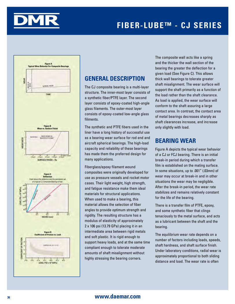
36 www.daemar.com
DMR FibER-lubE™ - CJ sERiEs
gEnERal dEsCRipTiOnThe CJ composite bearing is a multi-layer structure. The inner-most layer consists of a synthetic fiber/PTFE layer. The second layer consists of epoxy-coated high-angle glass filaments. The outer-most layer consists of epoxy-coated low-angle glass filiments.
The synthetic and PTFE fibers used in the liner have a long history of successful use as a bearing wear surface for rod end and aircraft spherical bearings. The high-load capacity and reliability of these bearings has made them the preferred design for many applications.
Fiberglass/epoxy filament wound composites were originally developed for use as pressure vessels and rocket motor cases. Their light weight, high strength, and fatigue resistance make them ideal materials for structural applications. When used to make a bearing, this material allows the selection of fiber angles to provide optimum strength and rigidity. The resulting structure has a modulus of elasticity of approximately 2 x 10⁶ psi (13.79 GPa) placing it in an intermediate area between rigid metals and soft plastic. It is rigid enough to support heavy loads, and at the same time compliant enough to tolerate moderate amounts of shaft misalignment without highly stressing the bearing corners.
The composite wall acts like a spring and the thicker the wall section of the bearing the greater the deflection for a given load (See Figure C). This allows thick wall bearings to tolerate greater shaft misalignment. The wear surface will support the shaft primarily as a function of the load rather than the shaft clearance. As load is applied, the wear surface will conform to the shaft assuring a large contact area. In contrast, the contact area of metal bearings decreases sharply as shaft clearances increase, and increase only slightly with load.
bEaRing WEaRFigure A depicts the typical wear behavior of a CJ or FCJ bearing. There is an initial break-in period during which a transfer film is established on the mating surface. In some situations, up to .001” (.03mm) of wear may occur at break-in and in other situations the wear may be negligible. After the break-in period, the wear rate stabilizes and remains relatively constant for the life of the bearing.
There is a transfer film of PTFE, epoxy, and some synthetic fiber that clings tenaciously to the metal surface, and acts as a lubricant between the shaft and the bearing.
The equilibrium wear rate depends on a number of factors including loads, speeds, shaft hardness, and shaft surface finish. Under laboratory conditions, radial wear is approximately proportional to both sliding distance and load. The wear rate is often
37www.daemar.com
DMR FibER-lubE™ - CJ sERiEs
reported as a factor K. This relationship can be expressed as follows:
W = KpVT
W = Radial wear in inches
K = Wear factor
P = Load in psi
V = Sliding velocity (ft/min)
T = Time in hours
The following tables show the actual measured wear factor for a number of conditions of oscillation and rotation. These values were obtained using Rc 50 shafts with a surface finish of 16 Ra (.4 μm). The wear factor would increase if the shaft material was softer or the surface finish rougher. The performance using the softer shafts was significantly lower, especially at the higher load condition. While performance is lower, it is adequate for many less demanding applications.
measured Wear Factor for CJ Composite bushings Type of Operations
p
lbs/in2
V
ft/min
K
in3 x min/lbs x ft x hr
Oscillation
±25°
229
4,900
15,000
43.6
2.0
.73
9.6x10⁻¹⁰
1.9x10⁻¹⁰
2.0x10⁻⁹
Rotation 64
64
256
512
78.5
157.0
39.3
39.3
39.8x10⁻¹⁰
24.9x10⁻¹⁰
14.9x10⁻¹⁰
12.4x10⁻¹⁰
measured Wear Factors for FCJ Composite bearingsType of
Operations
p
lbs/
in2
V
ft/min
K
in3 x min/
lbs x ft x hr
Oscillation
±25°
229
4,900
14,000
43.6
2.0
.73
7.4x10⁻¹⁰
1.6x10⁻¹⁰
5.52x10⁻¹⁰
Rotation 64
64
256
512
78.5
157.00
39.3
39.3
33.1x10⁻¹⁰
19.9x10⁻¹⁰
14.6x10⁻¹⁰
12.41x10⁻¹⁰
Using wear factors, the radial wear of a CJ bearing can be estimated by calculating W and adding .001” (.025 mm) for break-in wear. The liner can sustain .015-.020” (.38mm-.51mm) wear and still operate normally. Bearings having an inside diameter of over 2-1/2” have a thicker liner capable of sustaining .025” to .030” (.64mm - .76mm) wear. Surface finish affects wear rate as shown in (See Figure B) Field experience has shown that hard chrome plating gives excellent
wear performance and protects the shaft from corrosion. Softer coatings such as cadmium and zinc will not stand up in service and quickly wear off.
lOad CapaCiTyNormal application of load will cause a simple elastic deflection of the CJ bearing along with some permanent set. The set is primarily due to compaction of the synthetic fiber/PTFE liner.
We do not typically recommend subjecting the bearings to over 35,000 psi (241 MPa) load. In common with other materials, fiberglass/epoxy composites can undergo fatigue after repeated application of stress. Fatigue has not been a limiting factor in the use of the CJ bearing.
In fact, laboratory tests have shown that in many cases the bearing is more fatigue-resistant than the shaft. Laboratory tests show that the bearings fail by a gradual crushing action rather than a rapid catastrophic failure. This is consistent with typical composite behavior in which stress is supported by many fibers.
If one fiber breaks, the load is redistributed among the others. Breakage of the entire structure will not occur until a large number of the individual fibers are broken. CJ composite bearings can easily withstand over 35,000 psi (241 MPa) static load or 15,000 psi (103 MPa) dynamic load with a great deal of reliability.
In many cases, higher loading can be tolerated if the design and conditions of service are discussed fully with a technical representative.

38 www.daemar.com
DMR
Length to diameter ratio is also an important design consideration. Test results from the laboratory and the field have shown that the optimum performance can be attained by specifying
a length to inside diameter ratio (L/D) ranging from .5 to 2. When the L/D ratio of less than .5 is used, it is possible to create highly stressed areas at the corner of the bearing and cracking will occur at this location prematurely. If the L/D ratio is over 2, with any amount of shaft misalignment, cross corner jamming will occur and unit stresses can exceed the 15,000 psi (103 MPa) safe dynamic limit or the 35,000 psi (241 MPa) static limit of the bearings.
Bearings built with the proper L/D ratio will accept misalignment and shock load without premature failure.
COEFFiCiEnT OF FRiCTiOnThe coefficient of friction of a synthetic fiber/PTFE lined composite journal bearing running against a hardened Rc 50 steel shaft with a 16 Ra (.4 μm) surface, or less, varies from .02 to .25 depending on the load, the relative sliding velocity, and the bearing surface temperature. Generally, the coefficient of friction decreases with increasing load (See Figure D).
This information indicates that if the lowest coefficient of friction is desired, the
smallest bearing capable of sustaining the load should be used, and that the bearings are capable of performing best under peak operating conditions when temperatures and loads may be higher.
lubRiCaTiOnThe synthetic fiber/PTFE fabric wear surface of the CJ bearing is a self-contained boundary lubrication system; however, the addition of conventional lubricants often improves the overall performance of the CJ bearing.
“Lubricant” is a very general term, and it is often said that any liquid will act as a lubricant.
To some extent, this is true if hydrodynamic conditions are established, and the surfaces have minimal contact. The composite bearing, in earth moving equipment, operates generally in a state of boundary lubrication. Hydrocarbon oils are advantageous and can produce tenfold reductions in wear rates. Liquid lubricants can carry away heat and reduce the coefficient offriction. Greases can be used for lubrication, to prevent corrosion, and keep contamination out of the journal. In
FibER-lubE™ - CJ sERiEs
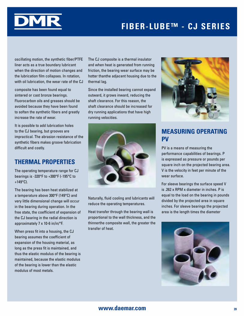
39www.daemar.com
DMR
oscillating motion, the synthetic fiber/PTFE liner acts as a true boundary lubricant when the direction of motion changes and the lubrication film collapses. In rotation, with oil lubrication, the wear rate of the CJ
composite has been found equal to sintered or cast bronze bearings. Fluorocarbon oils and greases should be avoided because they have been found to soften the synthetic fibers and greatly increase the rate of wear.
It is possible to add lubrication holes to the CJ bearing, but grooves are impractical. The abrasion resistance of the synthetic fibers makes groove fabrication difficult and costly.
ThERmal pROpERTiEsThe operating temperature range for CJ bearings is -320°F to +300°F (-195°C to +149°C).
The bearing has been heat stabilized at a temperature above 300°F (149°C) and very little dimensional change will occur in the bearing during operation. In the free state, the coefficient of expansion of the CJ bearing in the radial direction is approximately 7 x 10⁻⁶ in/in/°F.
When press fit into a housing, the CJ bearing assumes the coefficient of expansion of the housing material, as long as the press fit is maintained, and thus the elastic modulus of the bearing is maintained, because the elastic modulus of the bearing is lower than the elastic modulus of most metals.
The CJ composite is a thermal insulator and when heat is generated from running friction, the bearing wear surface may be hotter thanthe adjacent housing due to the thermal lag.
Since the installed bearing cannot expand outward, it grows inward, reducing the shaft clearance. For this reason, the shaft clearance should be increased for dry running applications that have high running velocities.
Naturally, fluid cooling and lubricants will reduce the operating temperatures.
Heat transfer through the bearing wall is proportional to the wall thickness, and the thinnerthe composite wall, the greater the transfer of heat.
mEasuRing OpERaTing pVPV is a means of measuring the performance capabilities of bearings. P is expressed as pressure or pounds per square inch on the projected bearing area. V is the velocity in feet per minute of the wear surface.
For sleeve bearings the surface speed V is .262 x RPM x diameter in inches. P is equal to the load on the bearing in pounds divided by the projected area in square inches. For sleeve bearings the projected area is the length times the diameter
FibER-lubE™ - CJ sERiEs
40 www.daemar.com
DMR
of the bearing. PV is then obtained by multiplying the P x V as shown in the following example:
3⁄4” Shaft @ 341 RPM; 90 lb. total load, bearing length 1”
V = .262 x RPM x Diameter or .262 x 341 x .750 = 67 ft/min
P = Total load ÷ projected area area = .750 x 1.0 = .75 in2
P = 90 lbs ÷ .75 = 120 psi PV = 120 psi x 67 fpm = 8040 PV
mEChaniCal pROpERTiEsThe CJ bearing has withstood static loads in excess of 50,000 psi (345 MPa) at room temperature. However, we do not generally recommend static loads in excess of 35,000 psi (241 MPa). At the recommended load limits, minimal crushing will occur. As the temperature increases, the load capacity of the bearing decreases. The composite backing tends to act as a shock absorber and reduces vibration. The maximum speed is 150 surface feet per minute for dry running applications.
CORROsiOn REsisTanCEThe CJ bearing is not affected by corrosive environments. Some solutions of highly concentrated acids will attack the backing material.
Specific information can be obtained from our Technical Service Department. The shaft should be stainless steel or chrome-plated if an alloy steel is used. The CJ bearing cannot rust, but when using a lubricant, it should contain a rust inhibitor to protect the shaft.
HT FibER-lubE™ - CJ sERiEs
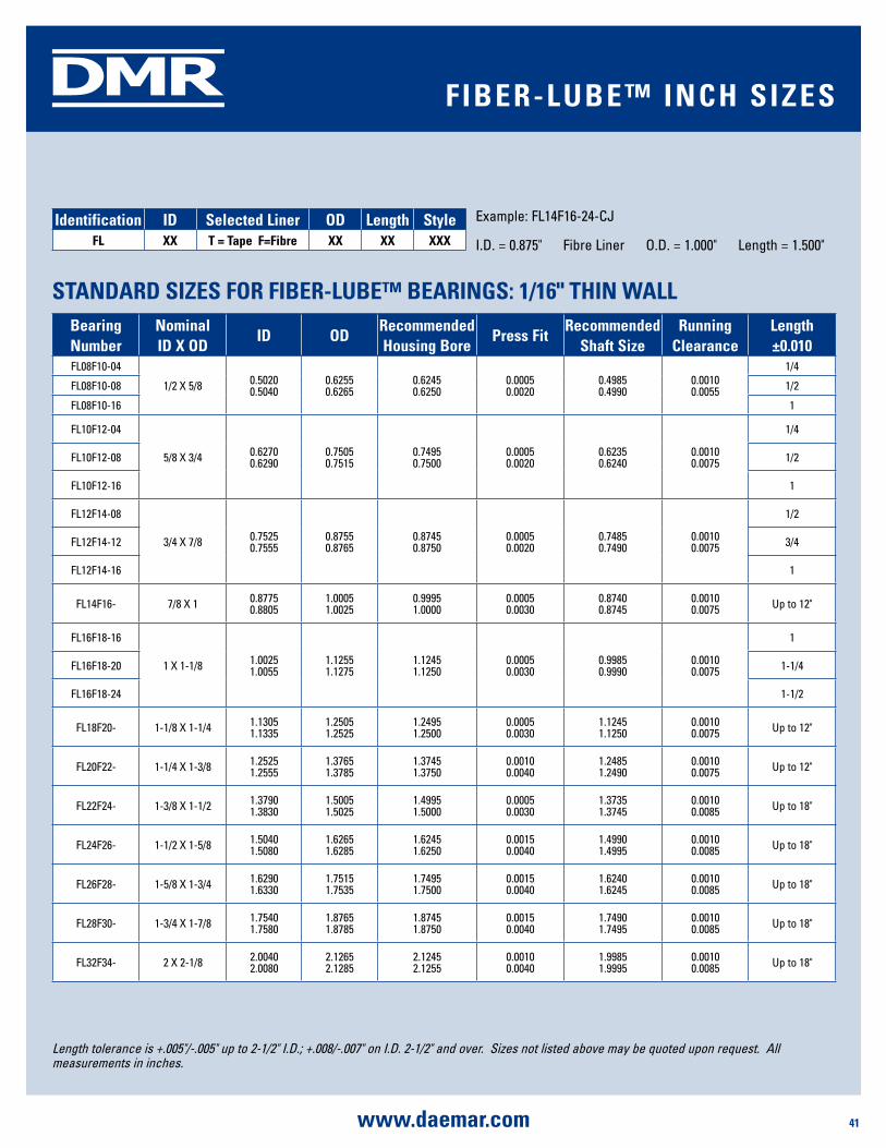
41www.daemar.com
DMR
bearing number
nominal id X Od
id OdRecommended housing bore
press FitRecommended
shaft sizeRunning
Clearancelength ±0.010
FL08F10-04
1/2 X 5/8 0.50200.5040
0.62550.6265
0.62450.6250
0.00050.0020
0.49850.4990
0.00100.0055
1/4
FL08F10-08 1/2
FL08F10-16 1
FL10F12-04
5/8 X 3/4 0.62700.6290
0.75050.7515
0.74950.7500
0.00050.0020
0.62350.6240
0.00100.0075
1/4
FL10F12-08 1/2
FL10F12-16 1
FL12F14-08
3/4 X 7/8 0.75250.7555
0.8755 0.8765
0.87450.8750
0.00050.0020
0.74850.7490
0.00100.0075
1/2
FL12F14-12 3/4
FL12F14-16 1
FL14F16- 7/8 X 1 0.87750.8805
1.00051.0025
0.99951.0000
0.00050.0030
0.87400.8745
0.00100.0075 Up to 12"
FL16F18-16
1 X 1-1/8 1.00251.0055
1.1255 1.1275
1.1245 1.1250
0.00050.0030
0.99850.9990
0.00100.0075
1
FL16F18-20 1-1/4
FL16F18-24 1-1/2
FL18F20- 1-1/8 X 1-1/4 1.13051.1335
1.2505 1.2525
1.2495 1.2500
0.00050.0030
1.12451.1250
0.00100.0075 Up to 12"
FL20F22- 1-1/4 X 1-3/8 1.25251.2555
1.3765 1.3785
1.3745 1.3750
0.0010 0.0040
1.24851.2490
0.00100.0075 Up to 12"
FL22F24- 1-3/8 X 1-1/2 1.37901.3830
1.5005 1.5025
1.4995 1.5000
0.00050.0030
1.37351.3745
0.00100.0085 Up to 18"
FL24F26- 1-1/2 X 1-5/8 1.50401.5080
1.6265 1.6285
1.6245 1.6250
0.0015 0.0040
1.49901.4995
0.00100.0085 Up to 18"
FL26F28- 1-5/8 X 1-3/4 1.62901.6330
1.7515 1.7535
1.7495 1.7500
0.00150.0040
1.62401.6245
0.00100.0085 Up to 18"
FL28F30- 1-3/4 X 1-7/8 1.75401.7580
1.8765 1.8785
1.8745 1.8750
0.0015 0.0040
1.74901.7495
0.00100.0085 Up to 18"
FL32F34- 2 X 2-1/8 2.00402.0080
2.1265 2.1285
2.1245 2.1255
0.0010 0.0040
1.99851.9995
0.00100.0085 Up to 18"
sTandaRd sizEs FOR FibER-lubE™ bEaRings: 1/16" Thin Wall
Length tolerance is +.005"/-.005" up to 2-1/2" I.D.; +.008/-.007" on I.D. 2-1/2" and over. Sizes not listed above may be quoted upon request. All measurements in inches.
identification id selected liner Od length styleFl XX T = Tape F=Fibre XX XX XXX
Example: FL14F16-24-CJ
I.D. = 0.875" Fibre Liner O.D. = 1.000" Length = 1.500"
FibER-lubE™ inCh sizEs

42 www.daemar.com
DMR
bearing number
nominal id id OdRecommended housing bore
press FitRecommended
shaft sizeRunning
Clearancelength ±0.010
FL08F12-08
1/2 X 3/4 0.50200.5040
0.75050.7515
0.74950.7500
0.00050.0020
0.51550.5160
0.00100.0055
1/2
FL08F12-12 3/4
FL08F12-16 1
FL10F14-08
5/8 X 7/8 0.62700.6290
0.8755 0.8765
0.8745 0.8750
0.00050.0020
0.6235 0.6240
0.00100.0055
1/2
FL10F14-12 3/4
FL10F14-16 1
FL12F16-08
3/4 X 1 0.75250.7555
1.00051.0025
0.99951.0000
0.00050.0030
0.74850.7490
0.00100.0075
1/2
FL12F16-12 3/4
FL12F16-16 1
FL14F18- 7/8 X 1-1/8 0.87750.8805
1.1255 1.1275
1.12451.1250
0.00050.0030
0.87400.8745
0.00100.0075 Up to 12"
FL16F20-08
1 X 1-1/4 1.00251.0055
1.25051.2525
1.24951.2500
0.00050.0030
0.99850.9990
0.00100.0075
1/2
FL16F20-10 5/8
FL16F20-12 3/4
FL16F20-16 1
FL16F20-20 1-1/4
FL18F22-08
1-1/8 X 1-3/8 1.13051.1335
1.3765 1.3785
1.3745 1.3750
0.0015 0.0040
1.24451.2450
0.00100.0080
1/2
FL18F22-16 1
FL18F22-32 2
FL20F24-16
1-1/4 X 1-1/2 1.25251.2555
1.5005 1.5025
1.4995 1.5000
0.0005 0.0030
1.24851.2490
0.00100.0080
1
FL20F24-24 1-1/2
FL20F24-32 2
FL22F26- 1-3/8 X 1-5/8 1.37901.3830
1.6265 1.6285
1.6245 1.6250
0.0015 0.0040
1.37351.3745
0.00100.0075 Up to 18"
FL24F28-24
1-1/2 X 1-3/4 1.50401.5080
1.7515 1.7535
1.7495 1.7500
0.0015 0.0040
1.49901.4995
0.00100.0085
1-1/2
FL24F28-32 2
FL24F28-48 3
FL26F30- 1-5/8 X 1-7/8 1.62901.6330
1.8765 1.8785
1.8745 1.8750
0.0015 0.0040
1.62401.6245
0.00100.0085 Up to 18"
FL28F32- 1-3/4 X 2 1.75401.7580
2.0015 2.0035
1.9995 2.0000
0.0015 0.0040
1.74901.7495
0.00100.0095 Up to 18"
FL32F36-24
2 X 2-1/4 2.00402.0080
2.2515 2.2535
2.24952.2505
0.0010 0.0040
1.99851.9995
0.00200.0110
1-1/2
FL32F36-32 2
FL32F36-48 3
FL36F40- 2-1/4 X 2-1/2 2.25402.2580
2.5020 2.5040
2.49952.5005
0.0015 0.0045
2.24852.2490
0.00200.0110 Up to 18"
sTandaRd sizEs FOR FibER-lubE™ bEaRings: 1/8" sTandaRd Wall
FibER-lubE™ inCh sizEs
Length tolerance is +.005"/-.005" up to 2-1/2" I.D.; +.008/-.007" on I.D. 2-1/2" and over. Sizes not listed above may be quoted upon request. All measurements in inches.
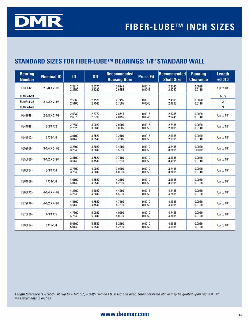
43www.daemar.com
DMR
sTandaRd sizEs FOR FibER-lubE™ bEaRings: 1/8" sTandaRd Wall sTandaRd sizEs FOR FibER-lubE™ bEaRings: 1/8" sTandaRd Wall
bearing number
nominal id id OdRecommended housing bore
press FitRecommended
shaft sizeRunning
Clearancelength ±0.010
FL38F42- 2-3/8 X 2-5/8 2.38102.3850
2.62702.6290
2.62452.6255
0.00150.0045
2.37402.3750
0.00200.0110 Up to 18"
FL40F44-24
2-1/2 X 2-3/4 2.50602.5100
2.75202.7540
2.74952.7505
0.00150.0045
2.49852.4995
0.00200.0110
1-1/2
FL40F44-32 2
FL40F44-48 3
FL42F46- 2-5/8 X 2-7/8 2.63302.6370
2.87702.8790
2.87452.8755
0.00150.0045
2.62352.6245
0.00200.0110 Up to 18"
FL44F48- 2-3/4 X 3 2.75802.7620
3.00203.0040
2.99903.0005
0.00150.0050
2.74852.7495
0.00200.0110 Up to 18"
FL48F52- 3 X 3-1/4 3.01003.0140
3.25203.2540
3.24903.2505
0.00150.0050
2.99852.9995
0.00200.0110 Up to 18"
FL52F56- 3-1/4 X 3-1/2 3.26003.2640
3.50203.5040
3.49903.5010
0.00100.0050
3.24853.2495
0.00200.01105 Up to 18"
FL56F60- 3-1/2 X 3-3/4 3.51003.5140
3.75203.7540
3.74903.7510
0.00100.0050
3.49853.4995
0.00200.0110 Up to 18"
FL60F64- 3-3/4 X 4 3.76003.7640
4.00204.0040
3.99904.0010
0.00100.0050
3.74853.7495
0.00200.0110 Up to 18"
FL64F68- 4 X 4-1/4 4.01004.0140
4.25204.2540
4.24904.2510
0.0010 0.0050
3.99853.9995
0.00300.0120 Up to 18"
FL68F72- 4-1/4 X 4-1/2 4.26004.2640
4.50204.5040
4.49904.5010
0.0015 0.0050
4.24854.2495
0.00300.0120 Up to 18"
FL72F76- 4-1/2 X 4-3/4 4.51004.5140
4.75204.7540
4.74904.7510
0.0010 0.0050
4.49854.4995
0.00300.0120 Up to 18"
FL76F80- 4-3/4 X 5 4.76004.7640
5.00205.0040
4.99905.0010
0.0010 0.0050
4.74854.7495
0.00300.0120 Up to 18"
FL80F84- 5 X 5-1/4 5.01005.0140
5.25205.2540
5.24905.2510
0.0010 0.0050
4.99854.9995
0.00300.0120 Up to 18"
FibER-lubE™ inCh sizEs
Length tolerance is +.005"/-.005" up to 2-1/2" I.D.; +.008/-.007" on I.D. 2-1/2" and over. Sizes not listed above may be quoted upon request. All measurements in inches.
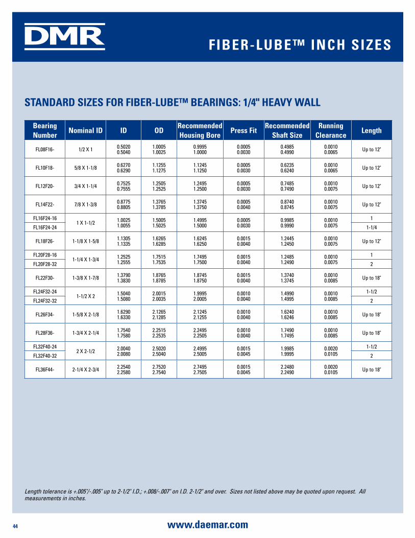
44 www.daemar.com
DMR
bearing number
nominal id id OdRecommended housing bore
press FitRecommended
shaft sizeRunning
Clearancelength
FL08F16- 1/2 X 1 0.50200.5040
1.00051.0025
0.99951.0000
0.0005 0.0030
0.49850.4990
0.00100.0065 Up to 12"
FL10F18- 5/8 X 1-1/8 0.62700.6290
1.12551.1275
1.12451.1250
0.0005 0.0030
0.62350.6240
0.00100.0065 Up to 12"
FL12F20- 3/4 X 1-1/4 0.75250.7555
1.25051.2525
1.24951.2500
0.0005 0.0030
0.74850.7490
0.00100.0075 Up to 12"
FL14F22- 7/8 X 1-3/8 0.87750.8805
1.37651.3785
1.37451.3750
0.0005 0.0040
0.87400.8745
0.00100.0075 Up to 12"
FL16F24-161 X 1-1/2 1.0025
1.00551.50051.5025
1.49951.5000
0.0005 0.0030
0.99850.9990
0.00100.0075
1
FL16F24-24 1-1/4
FL18F26- 1-1/8 X 1-5/8 1.13051.1335
1.62651.6285
1.62451.6250
0.0015 0.0040
1.24451.2450
0.00100.0075 Up to 12"
FL20F28-161-1/4 X 1-3/4 1.2525
1.25551.75151.7535
1.74951.7500
0.0015 0.0040
1.24851.2490
0.00100.0075
1
FL20F28-32 2
FL22F30- 1-3/8 X 1-7/8 1.37901.3830
1.87651.8785
1.87451.8750
0.0015 0.0040
1.37401.3745
0.00100.0085 Up to 18"
FL24F32-241-1/2 X 2 1.5040
1.50802.00152.0035
1.99952.0005
0.0010 0.0040
1.49901.4995
0.00100.0085
1-1/2
FL24F32-32 2
FL26F34- 1-5/8 X 2-1/8 1.62901.6330
2.12652.1285
2.12452.1255
0.0010 0.0040
1.62401.6246
0.00100.0085 Up to 18"
FL28F36- 1-3/4 X 2-1/4 1.75401.7580
2.25152.2535
2.24952.2505
0.0010 0.0040
1.74901.7495
0.00100.0085 Up to 18"
FL32F40-242 X 2-1/2 2.0040
2.00802.50202.5040
2.49952.5005
0.0015 0.0045
1.99851.9995
0.00200.0105
1-1/2
FL32F40-32 2
FL36F44- 2-1/4 X 2-3/4 2.25402.2580
2.75202.7540
2.74952.7505
0.0015 0.0045
2.24802.2490
0.00200.0105 Up to 18"
sTandaRd sizEs FOR FibER-lubE™ bEaRings: 1/4" hEaVy Wall
FibER-lubE™ inCh sizEs
Length tolerance is +.005"/-.005" up to 2-1/2" I.D.; +.008/-.007" on I.D. 2-1/2" and over. Sizes not listed above may be quoted upon request. All measurements in inches.

45www.daemar.com
DMR
sTandaRd sizEs FOR FibER-lubE™ bEaRings: 1/4" hEaVy Wall sTandaRd sizEs FOR FibER-lubE™ bEaRings: 1/4" hEaVy Wall dimEnsiOns
bearing number
nominal id id OdRecommended housing bore
press FitRecommended
shaft sizeRunning
Clearancelength
FL38F46- 2-3/8 X 2-7/8 2.38102.3850
2.87702.8790
2.87452.8755
0.00150.0045
2.37402.3750
0.00200.0105 Up to 18"
FL40F48- 2-1/2 X 3 2.50602.5100
3.00203.0040
2.99903.0005
0.00150.0050
2.49902.4995
0.00200.0105 Up to 18"
FL42F50- 2-5/8 X 3-1/8 2.63302.6370
3.12703.1290
3.12403.1255
0.00150.0050
2.62402.6245
0.00200.0105 Up to 18"
FL44F52- 2-3/4 X 3-1/4 2.75802.7620
3.25203.2540
3.24903.2505
0.00150.0050
2.74852.7495
0.00200.0105 Up to 18"
FL48F56- 3 X 3-1/2 3.01003.0140
3.50203.5040
3.49903.5010
0.00100.0050
2.99852.9995
0.00200.0105 Up to 18"
FL52F60- 3-1/4 X 3-3/4 3.26003.2640
3.75203.7540
3.74903.7510
0.00100.0050
3.24853.2495
0.00200.0105 Up to 18"
FL56F64- 3-1/2 X 4 3.51003.5140
4.00204.0040
3.99904.0010
0.00100.0050
3.49853.4995
0.00200.0105 Up to 18"
FL0F68- 3-3/4 X 4-1/4 3.76003.7640
4.25204.2540
4.24904.2510
0.00100.0050
3.74853.7495
0.00200.0105 Up to 18"
FL64F72- 4 X 4-1/2 4.01004.0140
4.50204.5040
4.49904.5010
0.0010 0.0050
3.99853.9995
0.00300.0120 Up to 18"
FL68F76- 4-1/4 X 4-3/4 4.26004.2640
4.75204.7540
4.74904.7510
0.0010 0.0050
4.24854.2495
0.00300.0120 Up to 18"
FL72F80- 4-1/2 X 5 4.51004.5140
5.00205.0040
4.99905.0010
0.0010 0.0050
4.49854.4995
0.00300.0120 Up to 18"
FL76F84- 4-3/4 X 5-1/4 4.76004.7640
5.25205.2540
5.24905.2510
0.0010 0.0050
4.74854.7495
0.00300.0120 Up to 18"
FL80F88- 5 X 5-1/2 5.01005.0140
5.50205.5040
5.49905.5010
0.0010 0.0050
4.99854.9995
0.00300.0120 Up to 18"
FibER-lubE™ inCh sizEs
Length tolerance is +.005"/-.005" up to 2-1/2" I.D.; +.008/-.007" on I.D. 2-1/2" and over. Sizes not listed above may be quoted upon request. All measurements in inches.

46 www.daemar.com
DMR
bearing number
nominal id X Od
id OdRecommended housing bore
press Fit
Recommended shaft size
length Tolerance
FLM012F017- 12 X 17 12.09312.143
17.04317.068
17.00017.018
.025
.06811.98212.000 +0.00 / -.25
FLM015F020- 15 X 20 15.09615.146
20.04620.071
20.00020.021
.025
.07114.98215.000 +0.00 / -.25
FLM018F023- 18 X 23 18.12118.201
23.04623.096
23.00023.021
.025
.09617.92818.000 +0.00 / -.25
FLM020F025- 20 X 25 20.12120.201
25.04625.096
25.00025.021
.025
.09619.97920.010 +0.00 / -.25
FLM022F027- 22 X 27 22.12122.201
27.04627.096
27.00027.021
.025
.09621.97922.000 +0.00 / -.25
FML025F030- 25 X 30 25.12525.205
30.05035.100
30.00030.025
.029
.10024.97925.000 +0.00 / -.25
FLM030F035- 30 X 35 30.12530.205
35.05035.100
35.00035.025
.025
.10029.79730.000 +0.00 / -.25
FLM035F040- 35 X 40 35.12535.225
40.05040.100
40.00040.025
.025
.10034.97535.000 +0.00 / -.25
FLM040F045- 40 X 45 40.12540.225
45.05045.100
45.00045.025
.025
.10039.97540.000 +0.00 / -.25
FLM045F050- 45 X 50 45.13045.230
50.05550.105
50.00050.025
.030
.10544.97545.000 +0.00 / -.25
FLM050F055- 50 X 55 50.15550.225
55.05555.105
55.00055.030
.025
.10549.97550.000 +0.00 / -.25
sTandaRd sizEs FOR FibER-lubE™ mETRiC bEaRings: 2.5mm Wall
Housing bore and shaft diameter tolerances: H7/H8 and h7/h8 respectively. Smaller tolerance in length is available on request. Measurements in millimeters.
Example: FLM040F048-40-CJ
I.D. = 40mm O.D. = 48mm Length = 40mm
FibER-lubE™ mETRiC sizEs
identification id selected liner Od length styleFlm XXX T = Tape F=Fibre XXX XX XXX
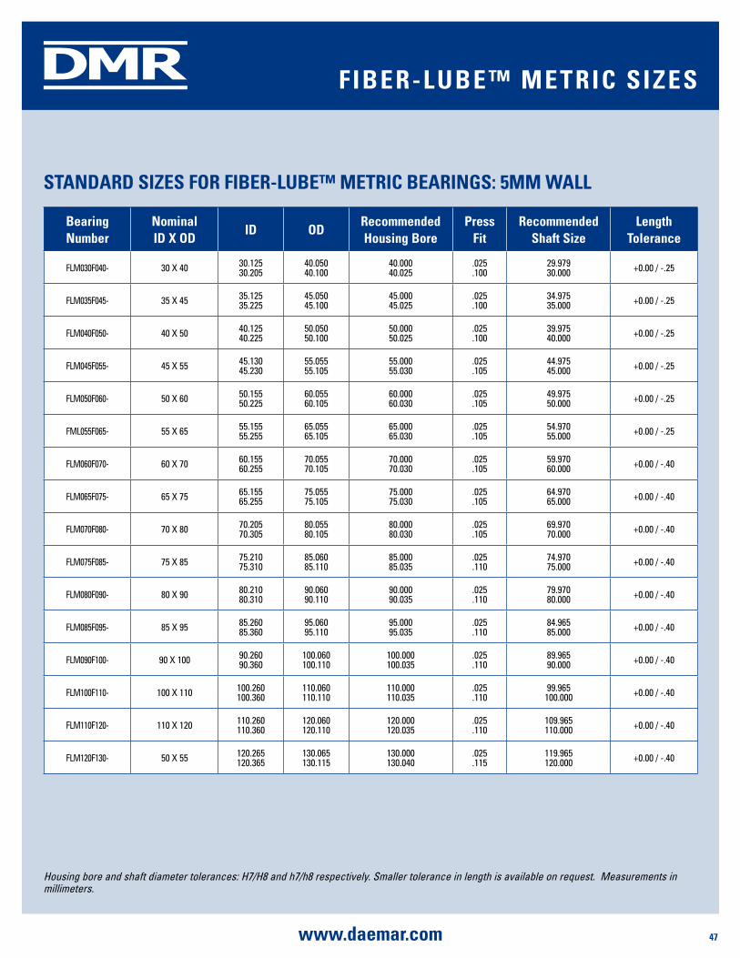
47www.daemar.com
DMR
bearing number
nominal id X Od
id OdRecommended housing bore
press Fit
Recommended shaft size
length Tolerance
FLM030F040- 30 X 40 30.12530.205
40.05040.100
40.00040.025
.025
.10029.97930.000 +0.00 / -.25
FLM035F045- 35 X 45 35.12535.225
45.05045.100
45.00045.025
.025
.10034.97535.000 +0.00 / -.25
FLM040F050- 40 X 50 40.12540.225
50.05050.100
50.00050.025
.025
.10039.97540.000 +0.00 / -.25
FLM045F055- 45 X 55 45.13045.230
55.05555.105
55.00055.030
.025
.10544.97545.000 +0.00 / -.25
FLM050F060- 50 X 60 50.15550.225
60.05560.105
60.00060.030
.025
.10549.97550.000 +0.00 / -.25
FML055F065- 55 X 65 55.15555.255
65.05565.105
65.00065.030
.025
.10554.97055.000 +0.00 / -.25
FLM060F070- 60 X 70 60.15560.255
70.05570.105
70.00070.030
.025
.10559.97060.000 +0.00 / -.40
FLM065F075- 65 X 75 65.15565.255
75.05575.105
75.00075.030
.025
.10564.97065.000 +0.00 / -.40
FLM070F080- 70 X 80 70.20570.305
80.05580.105
80.00080.030
.025
.10569.97070.000 +0.00 / -.40
FLM075F085- 75 X 85 75.21075.310
85.06085.110
85.00085.035
.025
.11074.97075.000 +0.00 / -.40
FLM080F090- 80 X 90 80.21080.310
90.06090.110
90.00090.035
.025
.11079.97080.000 +0.00 / -.40
FLM085F095- 85 X 95 85.26085.360
95.06095.110
95.00095.035
.025
.11084.96585.000 +0.00 / -.40
FLM090F100- 90 X 100 90.26090.360
100.060100.110
100.000100.035
.025
.11089.96590.000 +0.00 / -.40
FLM100F110- 100 X 110 100.260100.360
110.060110.110
110.000110.035
.025
.11099.965
100.000 +0.00 / -.40
FLM110F120- 110 X 120 110.260110.360
120.060120.110
120.000120.035
.025
.110109.965110.000 +0.00 / -.40
FLM120F130- 50 X 55 120.265120.365
130.065130.115
130.000130.040
.025
.115119.965120.000 +0.00 / -.40
sTandaRd sizEs FOR FibER-lubE™ mETRiC bEaRings: 2.5mm Wall
sTandaRd sizEs FOR FibER-lubE™ mETRiC bEaRings: 5mm Wall
FibER-lubE™ mETRiC sizEs
Housing bore and shaft diameter tolerances: H7/H8 and h7/h8 respectively. Smaller tolerance in length is available on request. Measurements in millimeters.
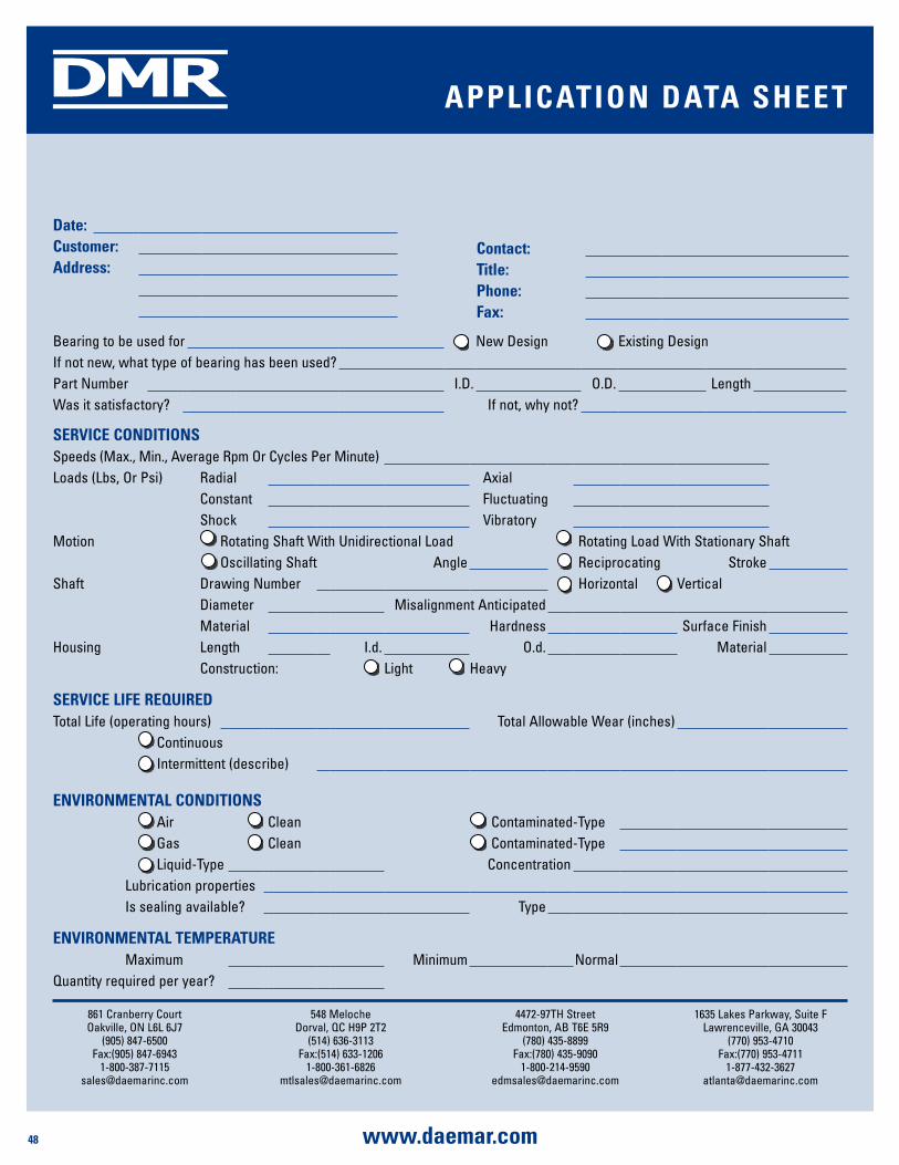
48 www.daemar.com
DMR
861 Cranberry CourtOakville, ON L6L 6J7
(905) 847-6500Fax:(905) 847-6943
548 MelocheDorval, QC H9P 2T2
(514) 636-3113Fax:(514) 633-1206
4472-97TH StreetEdmonton, AB T6E 5R9
(780) 435-8899Fax:(780) 435-9090
1635 Lakes Parkway, Suite FLawrenceville, GA 30043
(770) 953-4710Fax:(770) 953-4711
date:Customer:address:
Contact:Title:phone:Fax:
Bearing to be used for New Design Existing DesignIf not new, what type of bearing has been used?Part Number I.D. O.D. LengthWas it satisfactory? If not, why not?
sERViCE COndiTiOnsSpeeds (Max., Min., Average Rpm Or Cycles Per Minute)Loads (Lbs, Or Psi) Radial Axial
Constant FluctuatingShock Vibratory
Motion Rotating Shaft With Unidirectional Load Rotating Load With Stationary ShaftOscillating Shaft Angle Reciprocating Stroke
Shaft Drawing Number Horizontal VerticalDiameter Misalignment AnticipatedMaterial Hardness Surface Finish
Housing Length I.d. O.d. MaterialConstruction: Light Heavy
sERViCE liFE REquiREdTotal Life (operating hours) Total Allowable Wear (inches)
ContinuousIntermittent (describe)
EnViROnmEnTal COndiTiOnsAir Clean Contaminated-TypeGas Clean Contaminated-TypeLiquid-Type Concentration
Lubrication propertiesIs sealing available? Type
EnViROnmEnTal TEmpERaTuREMaximum Minimum Normal
Quantity required per year?
appliCaTiOn daTa shEET
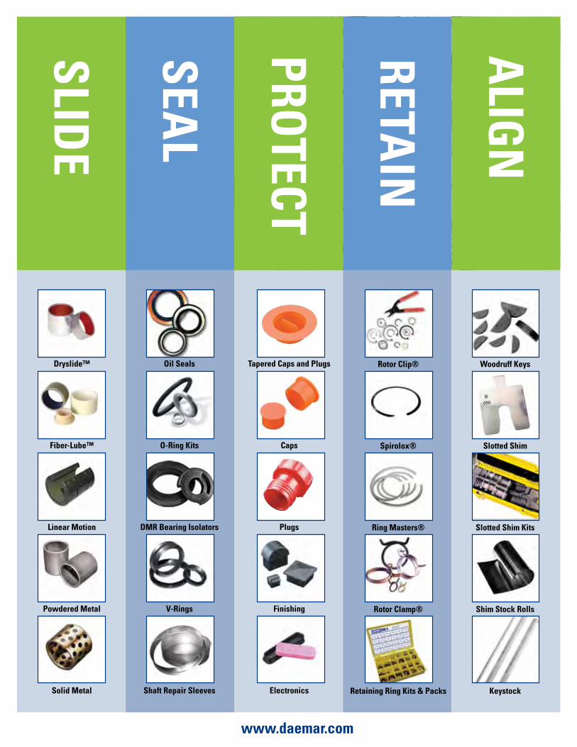
slidE
sEal
pROTECT
alig
n
RETain
dryslide™
Fiber-lube™
linear motion
powdered metal
solid metal
Oil seals
O-Ring Kits
dmR bearing isolators
V-Rings
shaft Repair sleeves
Rotor Clip®
spirolox®
Ring masters®
Rotor Clamp®
Retaining Ring Kits & packs
Tapered Caps and plugs
Caps
plugs
Finishing
Electronics
Woodruff Keys
slotted shim
slotted shim Kits
shim stock Rolls
Keystock
www.daemar.com
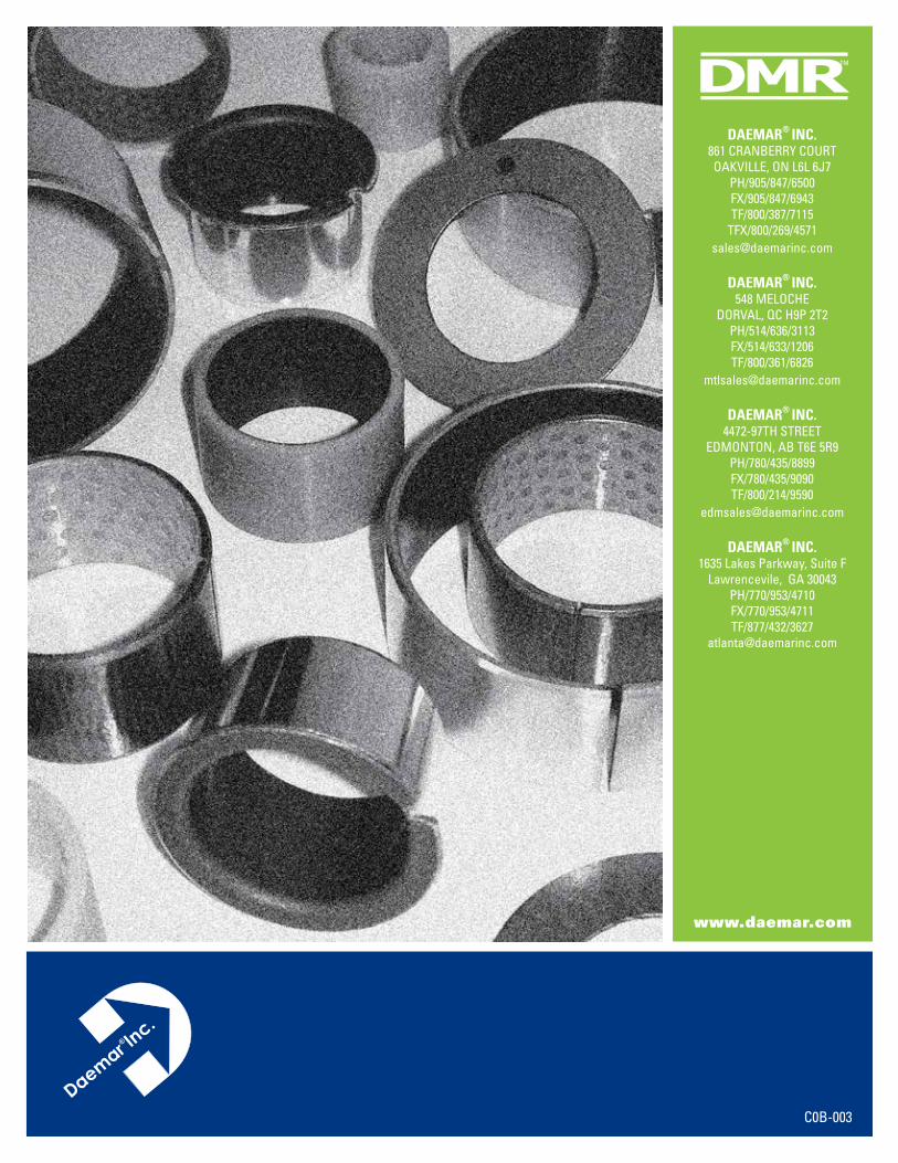
www.daemar.com
DMRTM
C0B-003
daEmaR® inC.861 CRANBERRY COURTOAKVILLE, ON L6L 6J7
PH/905/847/6500FX/905/847/6943TF/800/387/7115
TFX/800/269/[email protected]
daEmaR® inC.548 MELOCHE
DORVAL, QC H9P 2T2PH/514/636/3113FX/514/633/1206TF/800/361/6826
daEmaR® inC.4472-97TH STREET
EDMONTON, AB T6E 5R9PH/780/435/8899FX/780/435/9090TF/800/214/9590
daEmaR® inC.1635 Lakes Parkway, Suite F
Lawrencevile, GA 30043PH/770/953/4710FX/770/953/4711TF/877/432/3627