THX-CDL Control & Data Logger - thermomax … · USER & INSTALLATION MANUAL V2.2016 THX-CDL...
17
USER & INSTALLATION MANUAL V2.2016 www.thermomax-refrigeration.com THX-CDL Control & Data Logger Refrigeration
Transcript of THX-CDL Control & Data Logger - thermomax … · USER & INSTALLATION MANUAL V2.2016 THX-CDL...
USER & INSTALLATION MANUAL V2.2016
www.thermomax-refrigeration.com
THX-CDL Control & Data Logger
Refrigeration

TempControl | 3 2 | TempControl
Contents
PRESENTATION
Summary of Features 3
INSTALLATION
Safety Precautions 4
THX Unit 4
Sensors 4
Alarm Relay 4
Light Relay 4
Power Connection and Wiring Diagram 5
Battery 5
Wall & Panel Mount 6
Panel Mount diagrams 7
THX OPERATION 8
1.0 Main Screen 9
1.1 Status Screen 9
2.0 Settings Screens 10
2.1 System 10
• Cold-room temperature set point
• Cold-room Thermostat Differential
• Switch Delay
• Fan Mode
• Fan Enable Temperature
• Fan Stop Delay
• Defrost Mode
2.2 Set Clock 12
2.3 Scale 12
2.4 Calibration 12
2.5 Keypad 13
2.6 Language 13
2.7 Sample period 14
2.8 Password 14
2.9 Door 14
2.10 Network 15
2.11 Contrast 15
2.12 Energy Saving 15
2.13 Factory Settings 15
3.0 Defrost Screen 16
3.1 Manual Defrost 16
3.2 Defrost (cycle 1-6) 16
3.3 Defrost (cycle 7-12) 17
3.4 Defrost Schedule 18
4.0 Alarm Screen 18
4.1 Diagnostic Screen 20
4.2 Diagnostic Screen 2 21
5.0 Plot Screen 21
5.1 History 22
USB
1. Download Data 23
2. Download Setup 23
3. Upload Setup 23
4. Service 23
WEB SERVER
1. Live Data 25
2. Setup 26
3. User 27
4. Graph 27
5. Network 28
6. Download 28
SPECIFICATION 29
Presentation
SUMMARY OF FEATURES
• Power Supply 100 – 240V AC Mains
• Universal panel mount or wall mount box
• EN12830 certified
• CE tested
• On Board Web Server (IP addressable)
• Large data storage capacity
• USB Firmware Upgrade Functionality
• Backward compatible with old sensors (PT 100 terminated with RJ 11)
• IP54 Rated
• Module Auto-Detect and self-configuration
Controller
• Digital display of room and product temperature
• Digital display of evaporator
• Cold-room thermostat adjustable in 1°C steps with adjustable differential
• Compressor switching limiter for short-cycling prevention
• Fan enable thermostat
• Fully programmable defrost with adjustable duration, termination temperature and dwell period
• Manual defrost activation and override
• Energy saving mode
Datalogger
• Temperature from each channel can be set to sample every 1/5/15/30/60 minutes and stored to an internal databank
• Contents of internal databank can be transferred to the USB Flash Memory and viewed or transferred to the PC via website
• Battery Back-up up to 6hrs
Alarm
• 2-Stage high and low level alarms with mute facility
• Stage 1 temperature threshold with trigger delay
• Stage 2 limit temperature with immediate trigger
• Alarm history record for low alarm, high alarm and power fail
• Battery back-up for power-fail operation
• Summary screen for Alarm Overview
Note: The information supplied in this manual is for guidance only – no part of this may be used for any agreement, whether express or implied, or to form any contract.
BACK BOX
FRONT COVER
COMMS. AREA
FRONT LID

TempControl | 5 4 | TempControl
Installation
Note: This installation procedure is for guidance only, and its suitability should be verified by the installer.
SAFETY PRECAUTIONS
The following safety precautions are strongly recommended:
1. Before attempting to install and operate the unit, read the instruction and installation manual carefully.
2. Installation and any maintenance should only be carried out by suitably qualified personnel.
3. It is recommended that the unit be connected to the mains supply via a suitably rated isolating switch.
4. WARNING: When the unit is connected to the mains supply and the cover is open, the circuits at mains voltage will be exposed. Therefore when installing the unit, ensure all required connections (including battery connected, if included), are made and covers replaced before turning on the mains supply. Ensure that all the connections made are secure. If any maintenance work e.g. installing a new battery, is required ensure that the unit is isolated from the mains supply before removing the cover. Never leave the unit unattended if the cover has been removed and the mains supply is connected.
5. Do not exceed unit ratings as shown on the ratings label.
6. It is advisable to route mains cables away from low voltage or sensor cables.
(i) THX Unit
Note: For viewing comfort, the unit should be positioned at eye level. The ambient temperature of the unit is (0°C to +40°C). It is always good practice to keep electronic equipment away from cold, heat and electrical plant, as extremes of temperature may reduce the lifetime of the device, and heavy electrical loads, switches, relays or contactors too close to the device may cause electrical and electro-magnetic interference when switched on or off.
(ii) Sensors
The THX may be used with a variety of sensors of different cable lengths. If required, sensors are available with extended cable lengths or alternatively, sensor extenders are available also in a variety of lengths. If the sensors need to be extended, but factory-made extenders are not available, they can be extended using a suitable 3 or 4 core cable, according to the diagram shown below
• Install the ROOM sensor in the cold-room, ensuring that it is not too close to either the evaporator fan or the door. Position the sensor such that it reads the average cold-room temperature.
• Attach the EVAP sensor to the evaporator fins, ensuring that it is not too close to the defrost heater elements. Ideally, the sensor should measure the temperature of the evaporator coil, and should not be directly affected by the heater element. Therefore it is important to ensure good heat conduction between the evaporator tube and the sensor.
• Install the product sensor either to measure the air temperature or product temperature (or simulated product), as required, depending on the application. The THX uses the temperature measured by this sensor for logging purposes only.
Please note however, that as with all PT100 sensor applications, a good connection is vital. It is therefore recommended that wherever there is any doubt, a factory extended sensor or sensor extender should be used.
(iii) Alarm Relay
Note: The alarm relays are 3 contact arrangements which are isolated (volt-free). These relays may be used to trigger an external bell, warning lamp or digital communicator (telephone dialler).
Max rating of Alarm relays is 5A @ 240 VAC.
If the external device is used, connect the alarm as appropriate, according to the diagram opposite.
(iv) Light Relay
Max rating of Light relay is 5A @ 240 VAC.
Installation
(v) Power Connections and Wiring Diagram
Note: This device should be properly earthed. Flexible wires simplify connection to the terminals. All connections should be secure and adequately tightened. It is good practice to keep mains cables away from sensor cables and other low voltage signal cables.
Connect the supply to the unit, as per diagram below, using the appropriate input voltage according to the application.
(vi) Battery
The battery supplied is a 3.7V Lithium-polymer rechargeable battery and is plugged in but switched OFF. This should be switched ON after installation. See picture below. This battery is not essential for the system operation, but is used in the case of power failure, thereby continuing to log the 12 sensor inputs for approximately 6 hours.
The system parameters will remain intact, in the event of a power failure, however all interface options (Ethernet, screen, keypad options, USB etc. will not function as normal)
It is recommended that the battery is changed every 24 months, in order to maintain good power failure backup operation. When replacing, ensure that the type of rechargeable battery used is as specified.
(3.7V Lithium-polymer rechargeable battery)
WHITERED
BLUE
GREEN
GROUND
SENSE
COMPENSATE

TempControl | 7 6 | TempControl
Installation
WALL MOUNT1. Drill four holes in the wall, according to the template and insert
the wall plugs
2. Remove the Front Lid by unscrewing two screws
3. Disconnect the modules
4. Separate the front cover by unscrewing two screws
5. Remove the required knock outs from Back Box for the cables to pass through (always separate front cover before removing the knock outs)
6. Insert the cable glands
7. Screw in the Back Box to the wall
8. Pass the cables through the glands
9. Mount the Front Cover on the Back Box
10. Insert the modules
11. Connect the power supply cable and sensors
12. Tighten the cable glands
13. Mount the front lid
PANEL MOUNT (required panel mount kit)
1. Cut a hole in the panel with the described dimensions, (see page 7)
2. Remove the Front Lid unscrewing two screws
3. Disconnect the modules
4. Separate the front cover by unscrewing two screws
5. Remove the required knock outs from Back Box for the cables to pass through (always separate front cover before removing the knock outs). Ethernet cable can be passed through the hole which is under the label on the front cover (see picture below)
6. Attach the Panel Mount Seal, ensure that it is on the right position
7. Insert the Back Box into the panel cut out
8. Attach the four Panel Mount Fixing Clips (supplied), to the four studs at either side of the unit, (see page 7).
9. Tighten the four Panel Mount Fixing Screws
10. Insert the cable glands
11. Pass the cables through the glands
12. Mount the Front Cover on the Back Box
13. Insert the modules
14. Connect the power supply cable and sensors
15. Tighten the cable glands
16. Mount the front lid
Installation
296mm
50mm 50mm
169mm
177mm177mm 168mm 168mm
Right side view
Panel mount fixing clip
Panel mount fixing clip
Left side view
Panel mount fixing clip
Panel mount fixing clip
Panel mount fixing screw
Area required to be cut out for panel mount
Panel mount fixing screw
Panel mount fixing screw
Panel mount fixing screw

TempControl | 9 8 | TempControl
THX-CDL Operation
In order to fully understand the operation of the unit, this section should be read carefully.
(i) Graphic LCD Display
Displays all the information. The contrast is adjustable to suit the user. (Refer to section 2.11)
(ii) Navigation Keys
The six keys are used to navigate through the unit’s menus, allowing for easy access to the THX many options and settings. The four arrow keys select an option in the displayed menu, the key select the menu and the key returns to the previous menu.
(ii) Function Keys
There are six function keys on the THX2 unit:
Main Screen Alarm Screen
Settings Screen Plot Screen
Defrost Screen Esc/Light Switch (hold for 5 seconds to switch ON/OFF the light)
(iii) Indicators
Power ON/OFF Fan
Alarm Defrost
Compressor
1.0 MAIN SCREENS
To enter the Main Screen press the key.
I. Date and clock display
II. Cold-room temperature bar graph display
III. Product temperature bar graph display
IV. Display select indicator The highlighted box indicates which temperature is displayed The options are: E – Evaporator
R – Room (cold room)
P – Product (temperature only for logging purposes)
To change selection, use the keys, as appropriate.
Note: The evaporator temperature view is momentary only. The display will revert back to room temperature when the select key is released.
V. Digital display of selected temperature, with minimum/maximum indication. The minimum and maximum values are daily values and are reset at midnight every day.
VI. Internal databank indicator. This indicates the percentage ‘used’, in both bargraph and digital form.
VII. Buzzer Mute indicator
VIII. Settings lock indicator
IX. Battery status
X. Energy saving mode indicator
1.1 Status Screen
This screen displays the status of the Compressor, Door, Heater and Fan. To enter the Status Screen press the key twice.
THX-CDL Operation
OK

TempControl | 11 10 | TempControl
THX-CDL Operation THX-CDL Operation
2.0 SETTINGS SCREEN
To enter the Settings Screen press the key.
2.1 System
Select System from the Setting Screen and confirm selection using the key to enter the System Settings.
Cold-room temperature set point (-50°C to +50°C)
This is the thermostat temperature indicating the required cold-room temperature. Select ‘Coldroom Temp Set’ using the key and set the required temperature using and keys.
Cold-room Thermostat Differential (0°C to 10°C)
This is the differential (hysteresis) of the thermostat.
Note: if a differential of 2°C is selected, assuming a cold-room temperature of -8°C, the temperature has to rise to -6°C before the compressor will switch on, and then drop to -10°C before the compressor will switch off. The cold-room temperature deviation in this case will be -10°C to -6°C, i.e. 4°C. In general, the temperature deviation allowed by the system will always be twice the selected differential. In real life, the true temperature deviation will usually be more than the above, due to the delay in the response of the plant. Select ‘Therstat Difftial’ using the key and set the required temperature using and keys.
Switch Delay (0 – 99 min.)
This is a time delay to prevent the compressor from short-cycling. Each time the compressor is switched on, the timer is triggered. The compressor will subsequently not be allowed to switch on until the delay has expired. Select ‘Switch Delay’ using the key and set the required delay time using and keys.
Fan Mode
Select ‘Fan’ using the key and set the fan to RUN or STOP using the and keys.
Fan Enable Temperature
This is a thermostat, which disables fan operation any time the evaporator temperature exceeds this pre-set value. Its main use is to prevent warm air from being transferred into the cold-room immediately after a defrost cycle.
The fan thermostat has a built-in differential of +/-1°C, i.e. when the pre-set temperature is 0°C, the fan will switch on when the evaporator drops to -1°C, and will switch off when it rises to +1°C. Select ‘Fan Enable’ using the key and set the required temperature using the and keys.
Fan Stop Delay
This feature concerns users who utilise the ‘FAN STOP’ mode of operation. When a defrost cycle terminates in ‘FAN STOP’ mode, the fan will switch on only after the compressor switches on and this FAN DELAY period has expired. Select ‘Fan’ using the key and set the fan to STOP using the key. Select ‘Delay’ using the key and set the required delay time using the and keys.
Defrost Mode ‘ELECTRONIC’ Select ‘Defrost’ using the key and set the defrost to ELECTR using the key.
OK
▲
▼
▼
▲
▼
▼
▲
▼
▼
▲ ▼
▲
▼
▲
▼
▼
▲
▼
▼
▲
▼
▼

TempControl | 13 12 | TempControl
THX-CDL Operation THX-CDL Operation
Defrost Mode ‘HOT GAS’ Select ‘Defrost’ using the key and set the defrost to HOTGAS using the key.
2.2 Set Clock
The Set Clock screen allows the user to change the time and date settings of the unit. Select Set Clock from the Setting Screen and confirm selection using the key.
The highlighted parameter is adjusted by pressing the or key. The parameters are Year, Month, Day, Hour and Minutes. To change any of these, press the or key. Press the key to confirm the changes and back to the previous screen.
2.3 Scale
Select Scale from the Setting Screen and confirm selection using the key.
2.4 Calibration
Calibration trimming allows qualified personnel to adjust the Sensor Measurement by ±3°C / ±3%rH. A known reference value should be used.
Select Calibration from the Setting Screen and confirm selection using the key.
To enter the Calibration Trimming screen, press and hold the key for 8 seconds.
Use the keys to move to the channel that requires calibration trimming. Then use the or key to adjust the current temperature reading to the reference value read at the input.
2.5 Keypad
Select Keypad from the Setting Screen and confirm selection using the key. Enter the four digit password using the keys to access the menu. Confirm using the key.
To lock, press the key. To unlock, press the key. When the keypad is locked, the THX enter into a security mode, which renders the unit ‘tamper-proof’.
Default password: 0000
2.6 Language Select
Select Language Select from the Setting Screen and confirm selection using the key.
The language used by the THX to communicate the information may be selected here, i.e. English, German and French.
Use the or key to select the required language and then confirm the selection using the key.
✔ indicates the language that is currently selected.
Press the key to exit
OK
OK
OK
OK
OK
OK
OK▲ ▼
▲
▼
▲
▲
▼
▲
▼
▼
▼
OK
▼
▼
▲
▼
▲
▼
▼
▼

TempControl | 15 14 | TempControl
THX-CDL Operation THX-CDL Operation
2.7 Sample Period
Select Sample Period from the Setting Screen and confirm selection using the key.
Use the or key to select the required sample period and then confirm the selection using the key.
✔ indicates the sample period that is currently selected.
Press the key to exit.
2.8 Password
Select Password from the Setting Screen and confirm selection using the key.
The Password screen allows the user to change the password.
Enter the old and new password using the keys and confirm using the key.
Confirmation screen with new password will appear.
2.9 Door
Select Door from the Setting Screen and confirm selection using the key.
This screen allows the user to Enable or Disable the door switch. Use the key to enable or disable the door and confirm using key.
2.10 Network
Select Network from the Setting Screen and confirm selection using the key.
Please enter your network details or choose DHCP for Automatic Network Configuration. To set Automatic Network Configuration, use the key to select DHCP and use the key to select or deselect this option.
Indicates that the DHCP is OFF.
Indicates that the DHCP is ON.
Select and use the key to save the settings.
2.11 Contrast
Select Contrast from the Setting Screen and confirm selection using the key.
Use the keys to adjust the contrast
2.12 Energy Saving
Select Energy Saving from the Setting Screen and confirm selection using the key.
Select the required temperature, duration and start time using the keys and set the schedule.
2.13 Factory Settings
Select Factory Settings from the Setting Screen and confirm selection using the key.
OK
OK
OK
OK
OK
▼
OK
OK
▲ ▼
OK
OK
OK
OK
▲
▼
▼
OK▲▼
▼
▲
▼
▼
▼
▼
▼
TempControl | 17 16 | TempControl
THX-CDL Operation THX-CDL Operation
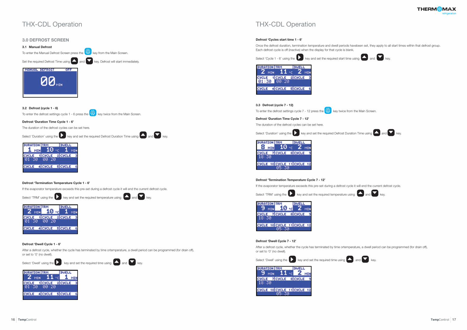
3.0 DEFROST SCREEN
3.1 Manual Defrost
To enter the Manual Defrost Screen press the key from the Main Screen. Set the required Defrost Time using and key. Defrost will start immediately.
3.2 Defrost (cycle 1 - 6)
To enter the defrost settings cycle 1 - 6 press the key twice from the Main Screen.
Defrost ‘Duration Time Cycle 1 - 6’
The duration of the defrost cycles can be set here. Select ‘Duration’ using the key and set the required Defrost Duration Time using and key.
Defrost ‘Termination Temperature Cycle 1 - 6’
If the evaporator temperature exceeds this pre-set during a defrost cycle it will end the current defrost cycle. Select ‘TRM’ using the key and set the required temperature using and key.
Defrost ‘Dwell Cycle 1 - 6’
After a defrost cycle, whether the cycle has terminated by time ortemperature, a dwell period can be programmed (for drain off), or set to ‘0’ (no dwell). Select ‘Dwell’ using the key and set the required time using and key.
.
Defrost ‘Cycles start time 1 - 6’
Once the defrost duration, termination temperature and dwell periods havebeen set, they apply to all start times within that defrost group. Each defrost cycle is off (inactive) when the display for that cycle is blank. Select ‘Cycle 1 - 6’ using the key and set the required start time using and key.
3.3 Defrost (cycle 7 - 12)
To enter the defrost settings cycle 7 - 12 press the key twice from the Main Screen.
Defrost ‘Duration Time Cycle 7 - 12’
The duration of the defrost cycles can be set here. Select ‘Duration’ using the key and set the required Defrost Duration Time using and key.
Defrost ‘Termination Temperature Cycle 7 - 12’
If the evaporator temperature exceeds this pre-set during a defrost cycle it will end the current defrost cycle. Select ‘TRM’ using the key and set the required temperature using and key.
Defrost ‘Dwell Cycle 7 - 12’
After a defrost cycle, whether the cycle has terminated by time ortemperature, a dwell period can be programmed (for drain off), or set to ‘0’ (no dwell). Select ‘Dwell’ using the key and set the required time using and key.
▲
▼
▼▲
▼
▼
▲
▼
▼▲
▼
▼
▲
▼
▼
▲
▼
▼
▲
▼
▼
▲ ▼

Defrost ‘Cycles start time 7 - 12’
Once the defrost duration, termination temperature and dwell periods have been set, they apply to all start times within that defrost group. Each defrost cycle is off (inactive) when the display for that cycle is blank. Select ‘Cycle 7 - 12’ using the key and set the required start time using and key.
3.4 Defrost Schedule
To enter the defrost schedule press the key four times from the Main Screen.
Select required days for the cycles 1-6 or 7-12 using the key and switch defrost ON using or OFF using key.
4.0 ALARM SCREEN
To enter the Alarm Screen press the key from the Main Screen.
Status Window
This window shows the current state of the system. If there are any warnings or messages, they will be displayed here. If everything is in good working condition, the message ‘OK’ is displayed here.
Alarm Mute
Select Status using the key and press the key. Select Mute using and key and confirm by pressing the key. Enter the four digit pin code and press the key.
Note: Also, pressing any key the alarm will be temporarily muted for 3 minutes.When the alarm system is reset, either manually or by the temperatures dropping back within their allowed limits, the alarm mute will automatically be cancelled.
Alarm Reset
Select Status using the key and press the key. Select Reset using and key and confirm by pressing the key. Enter the four digit pin code and press the key.
High Alarm Stage 1 Temperature (-99°C to +150°C)/Humidity (0%rH to 100%rH) Select High Alarm Max using the key and set the required temperature using and key.
The Stage 1 Alarm is a time/temperature related alarm. If the maximum threshold is exceeded, a timer is initiated, and no further action is taken at this time.
High Alarm Stage Delay (1-99 min.) Select High Alarm Delay using the key and set the required time using and key.
After the maximum threshold has been exceeded, the alarm will not be triggered until the timer exceeds the time delay set here. If the temperature drops below the threshold before the expiry of this delay, the timer is reset. If following this, the temperature rises above the threshold again, the timer restarts from zero.
High Alarm Limit Stage 2 temperature (-99°C to +150°C/Humidity (0%rH to 100%rH) Select High Alarm Limit using the key and set the required temperature using and key.
If at any time this limit is exceeded, the time delays will be overridden and the alarm will trigger immediately.
TempControl | 19 18 | TempControl
THX-CDL Operation THX-CDL Operation
OK
OK OK▲
▼
▼
▲
▼
▼
▲
▼
▼
OK
OK OK▲
▼
▼
▲
▼
▼
▲
▼
▼
▲
▼
▼

4.2 Diagnostic Screen 2
To enter the Diagnostic Screen 2 press the key twice from the Main Screen.
• UNIT NAME shows the name of the unit
• VERSION, this is the software version installed on the unit
• UNIT ID, this is the unit serial number
• MAC, this is the unique electronic signature of the unit
• The DATABANK window shows the capacity of the internal databank
• The DAYS FREE window shows the total number of days which have not yet been ‘used’
• The PERC FREE window shows the percentage of the databank which has not yet been ‘used’
• The TRANSF ON window shows the date on which the contents of theinternal databank need to be transferred.
5.0 PLOT SCREEN
To enter the Plot Screen press the key from the Main Screen.
This screen displays the plot of the temperature / humidity readings logged for the current day. The user can select any sensor using the and keys. The user can read sample information using the and keys.
TempControl | 21 20 | TempControl
THX-CDL Operation THX-CDL Operation
▲
▼
▼
▼
Low Alarm
All the functions described for the high alarm also apply to the low alarm.
Cycle Indication
This section of the status window is dedicated to the indication of which cycle is presently active, i.e. REFRIG (Refrigeration cycle), DEFST (Defrost cycle), and DWELL.
4.1 Diagnostic Screen
To enter the Diagnostic Screen press the key twice from the Main Screen.
This screen is continuously refreshed displaying the current state of the system.
The right margin of the screen displays the message ‘OK’ in front of each of the system’s units if that unit is in good working condition.
• The INPUT TYPE window shows which type of sensor is being used.
• The ROOM, EVAPORATOR and PRODUCT sensor calibration data is shown there, respectively. This information is for factory use and fault finding only.
• High Alarm monitor: This display shows the current state of the high alarm monitor, as well as the history. If there is a stage 1 delay timer in progress, this will show the time elapsed since the stage 1 maximum threshold was exceeded. If the alarm has already been triggered, it will show the time elapsed since it has been triggered. If the high alarm monitor is at rest, it will show the alarm history, i.e. the last time it was triggered.
• Low Alarm monitor: This display shows the current state of the low alarm monitor, as well as the history, similar to above.
• Mains-Fail Monitor: This display shows the current state of the mains-fail monitor, as well as the history. If there is a mains-fail in progress, it will show the time elapsed since the mains failed. If the mains supply is present, then the mains-fail history is displayed.

THX Controller can transfer data to/from a USB memory stick. The user can download the logged data and the unit settings to any USB memory device in FAT 32 format.
The USB memory key can also be used to load new unit settings; this is useful, for example, for importing the settings from a previously configured unit.
To enter to the USB menu, connect the USB stick to USB port when the Sensor Summary Screen is displayed.
1. Download Data
From the USB Menu screen, press key to reveal the Download Data Screen.
Use the or key to select the required channel and then confirm the selection using the key.
Choose the sample period from the pop-up menu using the or key and then confirm the selection using the key.
Choose another channel or select OK and confirm using the key. The download bar will appear indicate the downloading progress.
Do not remove the memory stick until the progress bar disappears. The data is saved to a file in ‘.csv’ format, compatible with Microsoft® Excel. The file name is automatically generated by the Data Logger.
2. Download Setup
From the Main Screen, press the key, followed by the key to select Download Setup in the menu and then confirm selection using the key to start download the settings. Do not remove the memory stick until the progress bar disappears. The data is saved to a file in ‘setup.txt’ format.
3. Upload Setup
From the Main Screen, press the key, followed by the key to select Upload Setup in the menu and then confirm selection using the key to start upload previously downloaded settings from the memory stick. Do not remove the memory stick until the progress bar disappears.
4. Service
For use only by authorised personnel and trained installers.
5.1 History
To enter the History press the key twice from the Main Screen.
Select the year, month and day using the and keys and press the key.
Functions that are available from this screen are as follows:
• By pressing the key, the values of the previous day will be displayed.
• By pressing the key, the unit will increment through the values, according to the sample period. At the end of each day, the next day logged in the databank will be displayed.
• By pressing the key, user can select the date
Use the keys to select the date and press the key to confirm.
TempControl | 23 22 | TempControl
THX-CDL Operation USB
OK
OK
OK
OK
▲▼
▲▼
OK
OK
OK▲ ▼
▼
▼
▼
▼
OK
OK ▼
OK
OK ▼

TempControl | 25 24 | TempControl
Web Server Web Server
To connect with unit’s embedded Web Server, connect unit to the network (switch, hub, router etc.) using Ethernet CAT-5 cable or directly to the network adapter on your computer and open a web browser - Windows Internet Explorer (version 8.0 or higher) or Firefox. Input the unit’s IP address (default -192.168.0.2).
Network connection
Direct connection
Enter the username and password (as provided below).
Default username and password:
User: user
Password: password
1. Live Data
Live data screen displays the current unit and relays status, firmware version, ID, databank status and temperature readings. The screen is refreshing every 10 seconds.
To change the language, click on the suitable flag as outlined below.

TempControl | 27 26 | TempControl
Web Server Web Server
2. Setup
Setup screen display settings for each channel and allows user to edit them. Choose the channel for which you want to change the settings and edit them:
• switch channel ON or OFF
• choose the sensor type
Setup screen display settings and allows user to edit them.
• Compressor (enter required coldroom temperature, thermostat hysteresis, switch delay and click to save)
• FAN (set fan to RUN or STOP and enter Stop Temp., Delay and click to save)
• Energy Saving (enter required coldroom temp., set the schedule and click to save)
• Defrost (choose the defrost type and set the schedule, click to save)
• Alarm (set the HI and LO alarm settings, click to save)
• Databank (choose the sample period and click to save)
• Time (set the current time and click to save)
• Factory Settings (click and confirm to restore the factory settings)
3. User
User screen allows user to change the username and password.
To change the password enter old username and password, then enter new username and password, confirm password and click the button.
4. Graph
Graph screen allows user to generate multiple channel graph.
To generate the graph, set the date , choose the channels and click on the button. User can set the graph scale using buttons.
Note: Java JRE 6 or higher required.

5. Network
Network screen display network setting for the unit and allow user to change them.
Please enter your network details or choose DHCP for Automatic Network Configuration.
To set Automatic Network Configuration, click on the and click the button to save.
Indicates that the DHCP is OFF.
Indicates that the DHCP is ON.
6. Download
Set the required time period or tick , choose the channel and
click to download.
Click to save the data on hard drive.
Note: Java JRE 6 or higher required.
TempControl | 29 28 | TempControl
Web Server Specification
ELECTRICAL
Supply Voltage: 110-240V AC Single Phase
Fuses: 1A 20mm Slow Blow
Relay Outputs: Alarm: 5A changeover 2 pin isolated – (volt free contacts)
Fan Relay:10A single pole
Heater Relay: 13A single pole
Compressor Relay: 13A single pole
Light Relay: 5A single pole
Ambient Temperature: 0°C to +40°C
MECHANICAL:
Dimensions: width: 300mm height: 100mm depth: 180mm weight: 1.5kg sensor: (each) 0.13kg
Box Material: Plastic
Display: Large LCD with backlight
SENSORS:
Type: SX™ PT 100 Platinum Film
Compensation: 3 wire compensated
Cable Length: A variety of lengths are available from 5m to 50m
Battery: 3.7V Lithium polymer 1000mAh with built-in protection
ACCESSORIES:
• Sensor (5m Cable)
• Sensor (15m Cable)
• Sensor (25m Cable)
• Sensor Extender 10, 50m
• Humidity Sensor
• Panel Mount Kit
• Wall Bracket for Humidity Sensor

30 | TempControl 31
WALL MOUNT TEMPLATE

In keeping with Company policy of continuing research and development and in order to offer our clients the most advanced products, Kingspan Environmental reserves the right to alter specifications and drawings without prior notice.
Issue No. 3: July 2016
019265
Head OfficeKingspan Environmental180 Gilford Road
Portadown
Co. Armagh
BT63 5LF
Tel: +44 (0) 28 3836 4400
UK Sales/Technical Enquiries:
Tel: +44 (0) 28 3836 4596
Email: [email protected]
Europe Sales/Technical Enquiries
Tel: +49 (0) 6102 3686712
Email: [email protected]