Bushing Power Factor Testing: In-Depth
149
© OMICRON Page 1 Bushing Power Factor Testing: In-Depth
Transcript of Bushing Power Factor Testing: In-Depth

© OMICRON Page 1
Bushing Power Factor Testing:
In-Depth
© OMICRON Page 2© OMICRON Page 2
Copyrighted 2018 by OMICRON electronics Corp USA
All rights reserved.
No part of this presentation may be reproduced or transmitted in any form or
by any means, electronic or mechanical, including photocopying, recording, or
any information storage or retrieval system or method, now known or
hereinafter invented or adopted, without the express prior written permission of
OMICRON electronics Corp USA.
© OMICRON
© OMICRON Page 3© OMICRON Page 3
Author Biography
© OMICRON Page 4© OMICRON Page 4
Transformer Testing Support Contacts
Fabiana Cirino
Application Engineer
OMICRON electronics Corp. USA
3550 Willowbend Blvd.
Houston, TX 77054 | USA
T +1 800 OMICRON
T +1 713 212 6154
M +1 832 454 6943
www.omicronenergy.com
Brandon Dupuis
Primary Application Engineer
OMICRON electronics Corp. USA
60 Hickory Drive
Waltham MA 02451 | USA
T +1 800 OMICRON
T +1 781 672 6230
M +1 781 254 8168
www.omicronenergy.com
Logan Merrill
Primary Application Engineer
OMICRON electronics Corp. USA
60 Hickory Drive
Waltham MA 02451 | USA
T +1 800 OMICRON
T +1 781 672 6216
M +1 617 947 6808
www.omicronenergy.com
Charles Sweetser
PRIM Engineering Services Manager
OMICRON electronics Corp. USA
60 Hickory Drive
Waltham MA 02451 | UNITED STATES
T +1 800 OMICRON
T +1 781 672 6214
M +1 617 901 6180
www.omicronusa.com
© OMICRON Page 5© OMICRON Page 5
2019 OMICRON Academy Transformer Trainings
January 30th and 31st – Houston, TX
https://www.omicronenergy.com/en/events/training/detail/electrical-diagnostic-
testing-of-power-transformers/471/
April 16th and 17th – Toronto, ON
https://www.omicronenergy.com/en/events/training/detail/electrical-diagnostic-
testing-of-power-transformers/472/
August 28th and 29th – Houston, TX
https://www.omicronenergy.com/en/events/training/detail/electrical-diagnostic-
testing-of-power-transformers/171/

© OMICRON Page 6© OMICRON Page 6
Bushing Power Factor Testing: In-Depth
1) An Introduction to Bushing Power Factor Testing
2) An Introduction to Performing Power Factor Sweep Tests on Bushings
3) Bushing Power Factor Test Analysis
4) Bushing C1 Power Factor Test Examples
5) Using the Power Factor Sweep Tests to Identify Invalid Bushing Measurements
© OMICRON Page 7© OMICRON Page 7
6) Bushing C2 Power Factor Test Examples
7) Energized Collar (Hot Collar) Test Examples
8) A Bushing’s Influence on the Overall Power Factor Test
9) Troubleshooting a Questionable Bushing Power Factor Test
10) Testing a Spare Bushing (Outside of a Transformer)
Bushing Power Factor Testing: In-Depth
© OMICRON Page 8
Bushing Power Factor Testing:
In-Depth

© OMICRON Page 9© OMICRON Page 9
Bushing Power Factor Tests
• Performing routine Power Factor measurements on bushings is critical
for extending the life of a power transformer
• Bushing insulation problems can be detected by performing periodic electrical
tests,
o C1 Power Factor Test – A “bushing tap” is required
o C2 Power Factor Test – A “bushing tap” is required
o Energized/Hot Collar Test – A “bushing tap” is NOT required
© OMICRON Page 10© OMICRON Page 10
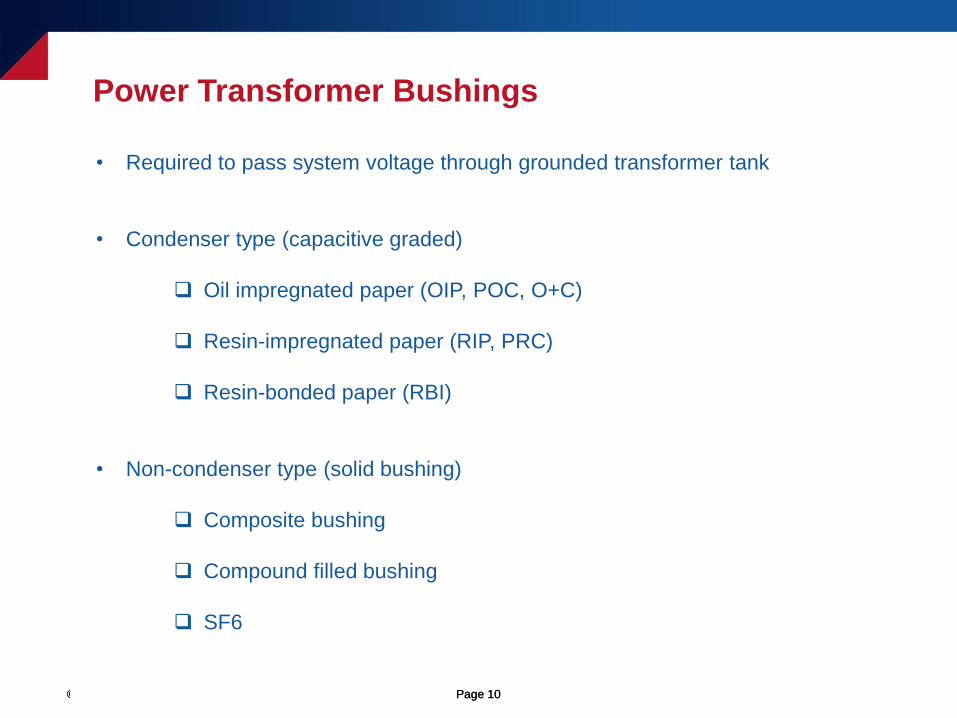
Power Transformer Bushings
• Required to pass system voltage through grounded transformer tank
• Condenser type (capacitive graded)
Oil impregnated paper (OIP, POC, O+C)
Resin-impregnated paper (RIP, PRC)
Resin-bonded paper (RBI)
• Non-condenser type (solid bushing)
Composite bushing
Compound filled bushing
SF6
© OMICRON Page 11© OMICRON Page 11
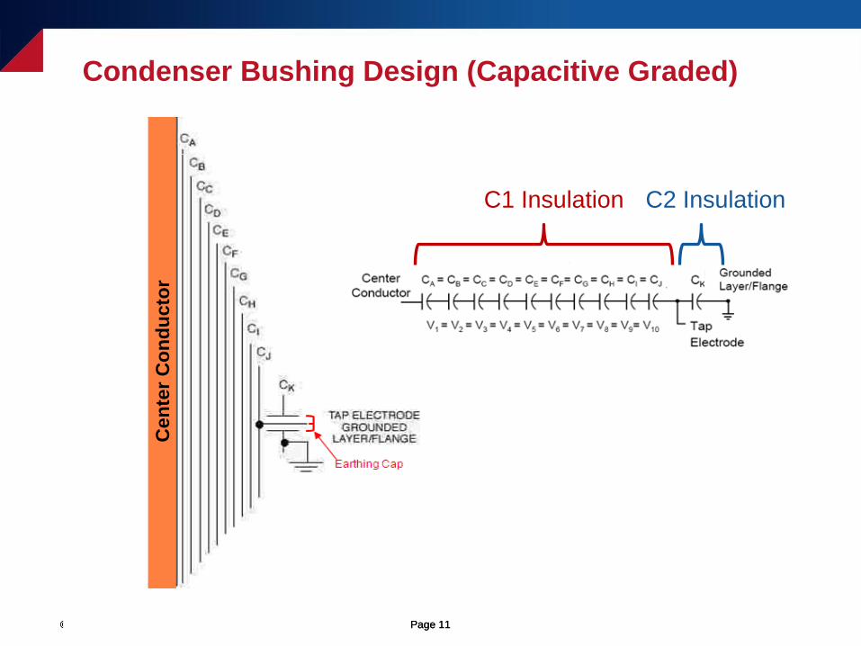
Condenser Bushing Design (Capacitive Graded)
Ce
nte
r C
on
du
cto
r
C1 Insulation C2 Insulation
© OMICRON Page 12© OMICRON Page 12
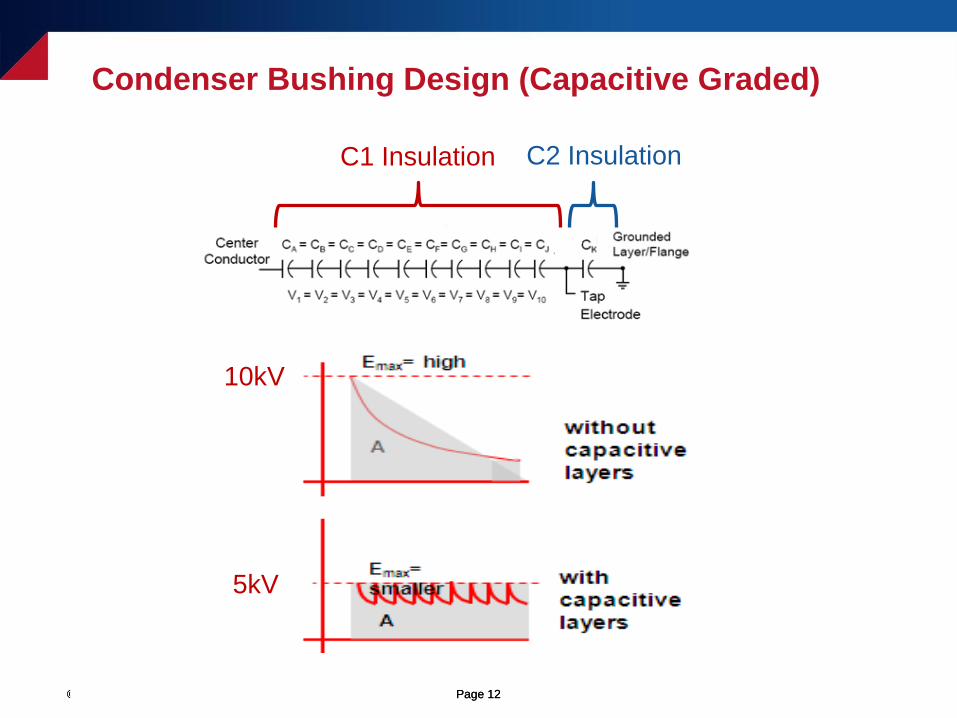
Condenser Bushing Design (Capacitive Graded)
C1 Insulation C2 Insulation
10kV
5kV
© OMICRON Page 13© OMICRON Page 13
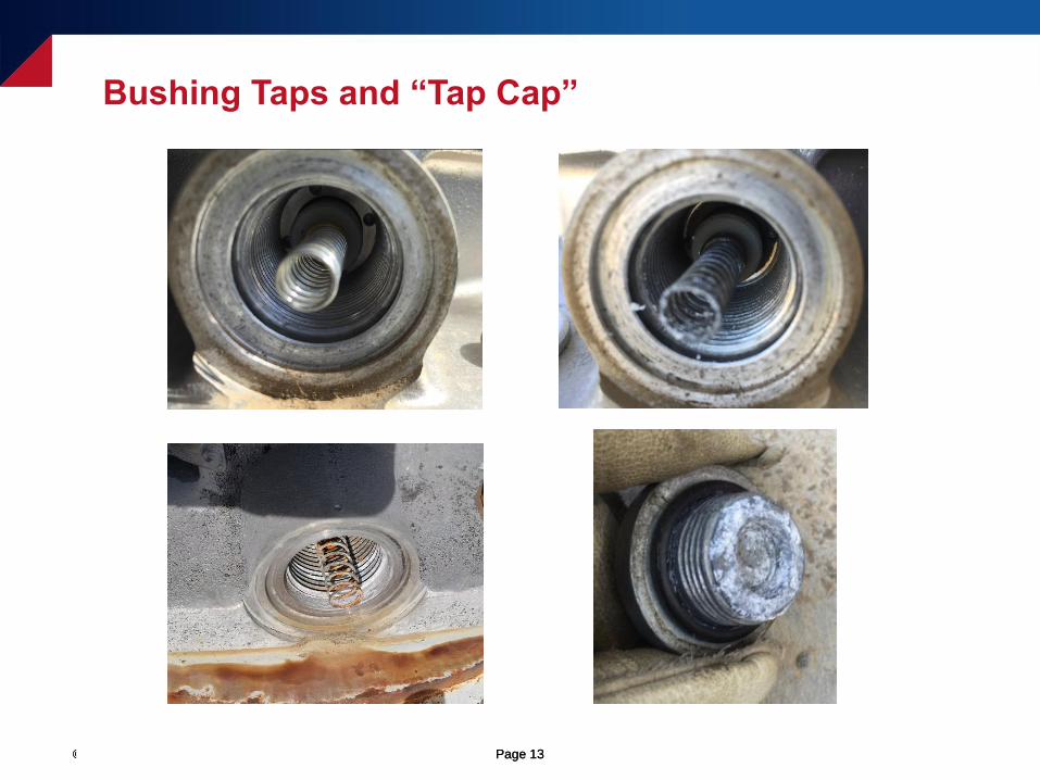
Bushing Taps and “Tap Cap”
© OMICRON Page 14© OMICRON Page 14
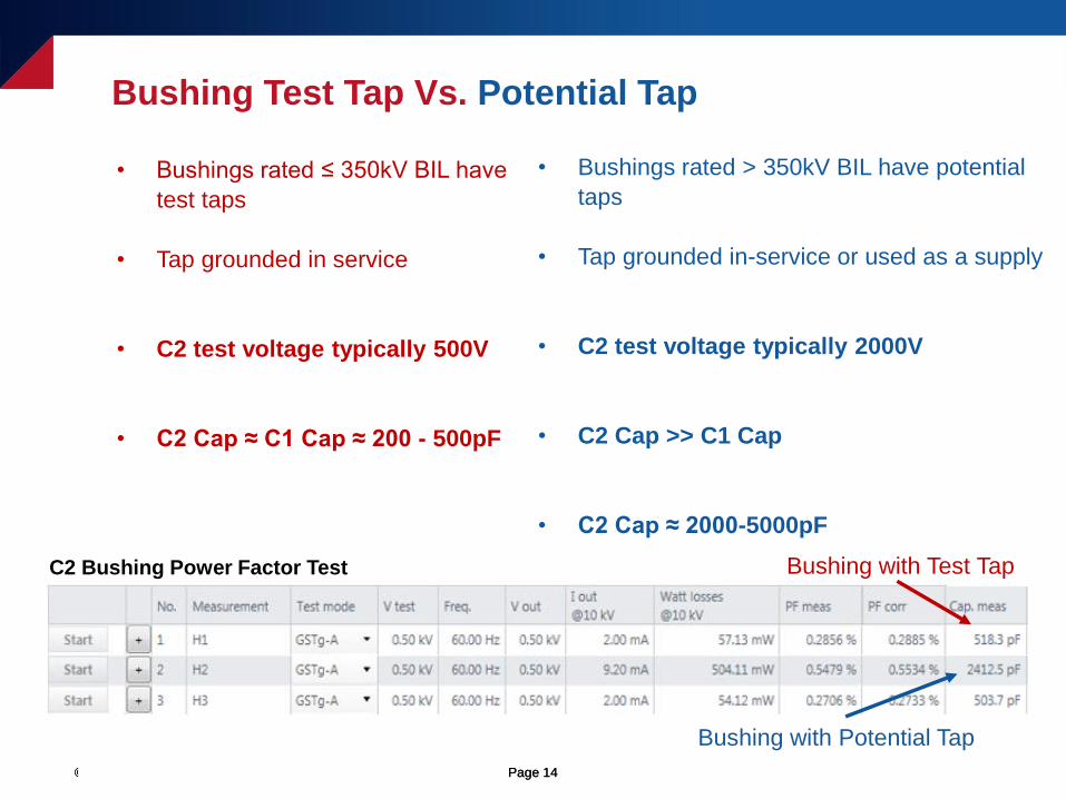
Bushing Test Tap Vs. Potential Tap
• Bushings rated ≤ 350kV BIL have
test taps
• Tap grounded in service
• C2 test voltage typically 500V
• C2 Cap ≈ C1 Cap ≈ 200 - 500pF
• Bushings rated > 350kV BIL have potential
taps
• Tap grounded in-service or used as a supply
• C2 test voltage typically 2000V
• C2 Cap >> C1 Cap
• C2 Cap ≈ 2000-5000pF
Bushing with Potential Tap
Bushing with Test TapC2 Bushing Power Factor Test
© OMICRON Page 15© OMICRON Page 15
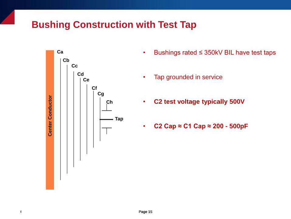
Bushing Construction with Test Tap
• Bushings rated ≤ 350kV BIL have test taps
• Tap grounded in service
• C2 test voltage typically 500V
• C2 Cap ≈ C1 Cap ≈ 200 - 500pF
Ca
CbCc
CdCe
CfCg
Ch
Tap
Cen
ter
Co
nd
ucto
r
© OMICRON Page 16© OMICRON Page 16
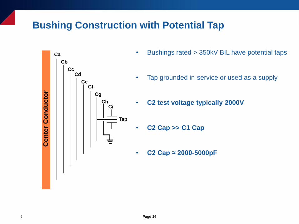
Bushing Construction with Potential Tap
• Bushings rated > 350kV BIL have potential taps
• Tap grounded in-service or used as a supply
• C2 test voltage typically 2000V
• C2 Cap >> C1 Cap
• C2 Cap ≈ 2000-5000pF
Ca
Cb
CcCd
CeCf
Cg
Ch
Tap
Ci
Cen
ter
Co
nd
ucto
r
© OMICRON Page 17© OMICRON Page 17
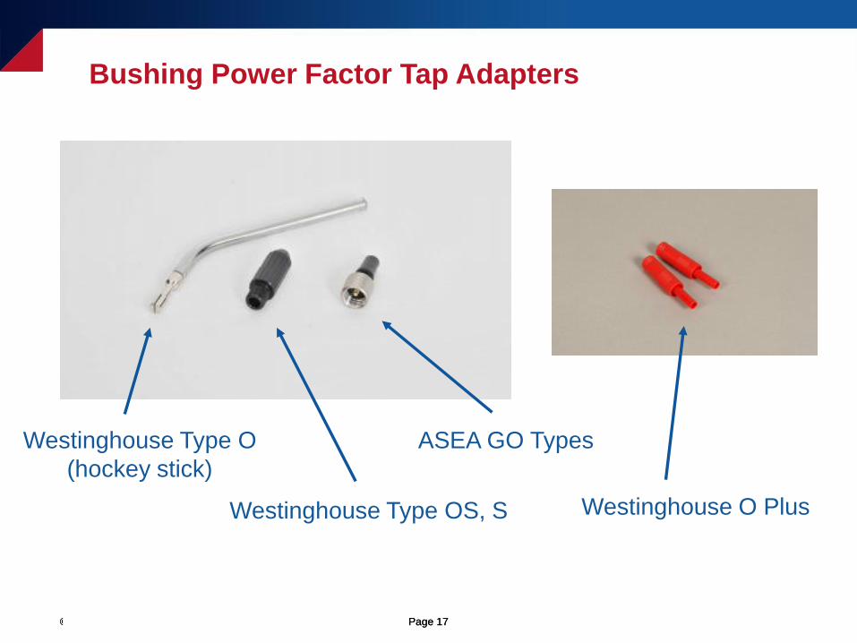
Bushing Power Factor Tap Adapters
Westinghouse Type O
(hockey stick)
Westinghouse Type OS, S
ASEA GO Types
Westinghouse O Plus
© OMICRON Page 18© OMICRON Page 18
“The Power Factor Checklist"
• The Power Factor measurement is highly sensitive, and is one of the most difficult
measurements to “get right” (i.e. to perform correctly)
• The “Power Factor checklist” is a series of steps that must be observed, when performing a
Power Factor measurement on an insulation system, to ensure that the correct measurement is
obtained
• Failure to observe all the steps in the “Power Factor checklist” often results in “bad”
Power Factor measurements (i.e. invalid Power Factor measurements)
© OMICRON Page 19© OMICRON Page 19
“The Power Factor Checklist"
Is the transformer tank solidly grounded to earth-potential?
Is the test-equipment solidly grounded to earth-potential?
Are the bushing terminals of the transformer completely disconnected and
isolated from any cable, bus-bar, support insulators, surge arrestors, etc.?
When applying a test-voltage of 10kV, a minimum clearance of 3in. must be
observed (which is the minimum distance required between the bushing
terminals that are energized, and any other surface at a different potential)
Avoid using a rubber blanket or any other insulator to isolate the bushing
terminals from any other surface at a different potential
Are the surfaces of the bushings clean and dry? People often do not respect how
significantly moisture on the bushings can influence a Power Factor measurement
If the bushings have a porcelain exterior use Windex or Colonite
If the bushings have a silicone exterior use a clean, dry rag
© OMICRON Page 20© OMICRON Page 20
What Should I Use to Clean and Dry the Bushings?
• Use a clean, dry rag
• Use Windex
• Use Collinite
• Use a Heat gun
• Do NOT use alcohol – The application of the alcohol will cool the surface of the
bushings and attract moisture
© OMICRON Page 21© OMICRON Page 21
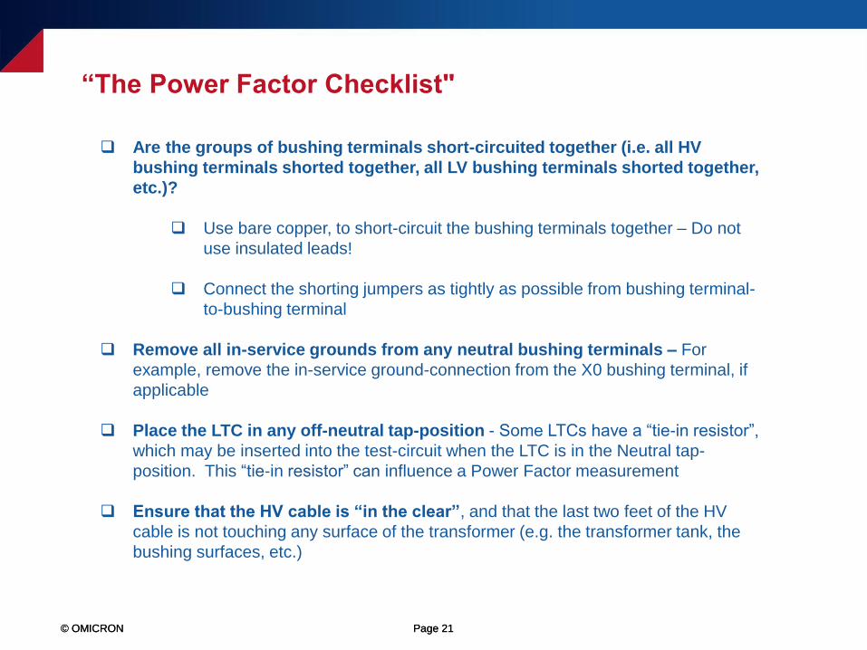
Are the groups of bushing terminals short-circuited together (i.e. all HV
bushing terminals shorted together, all LV bushing terminals shorted together,
etc.)?
Use bare copper, to short-circuit the bushing terminals together – Do not
use insulated leads!
Connect the shorting jumpers as tightly as possible from bushing terminal-
to-bushing terminal
Remove all in-service grounds from any neutral bushing terminals – For
example, remove the in-service ground-connection from the X0 bushing terminal, if
applicable
Place the LTC in any off-neutral tap-position - Some LTCs have a “tie-in resistor”,
which may be inserted into the test-circuit when the LTC is in the Neutral tap-
position. This “tie-in resistor” can influence a Power Factor measurement
Ensure that the HV cable is “in the clear”, and that the last two feet of the HV
cable is not touching any surface of the transformer (e.g. the transformer tank, the
bushing surfaces, etc.)
“The Power Factor Checklist"
© OMICRON Page 22© OMICRON Page 22
Do not Power Factor test in the rain
Avoid testing in high-humidity situations
Do not Power Factor test when the temperature of the oil is close-to, or below, 5°C
Power Factor test after lunch, if possible
“The Power Factor Checklist”
© OMICRON Page 23© OMICRON Page 23
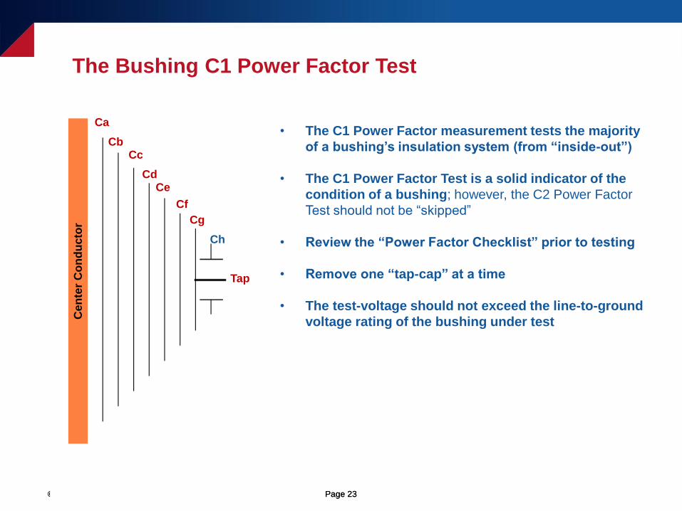
The Bushing C1 Power Factor Test
Ca
CbCc
CdCe
Cf
Cg
Ch
Tap
Cen
ter
Co
nd
ucto
r
• The C1 Power Factor measurement tests the majority
of a bushing’s insulation system (from “inside-out”)
• The C1 Power Factor Test is a solid indicator of the
condition of a bushing; however, the C2 Power Factor
Test should not be “skipped”
• Review the “Power Factor Checklist” prior to testing
• Remove one “tap-cap” at a time
• The test-voltage should not exceed the line-to-ground
voltage rating of the bushing under test
© OMICRON Page 24© OMICRON Page 24
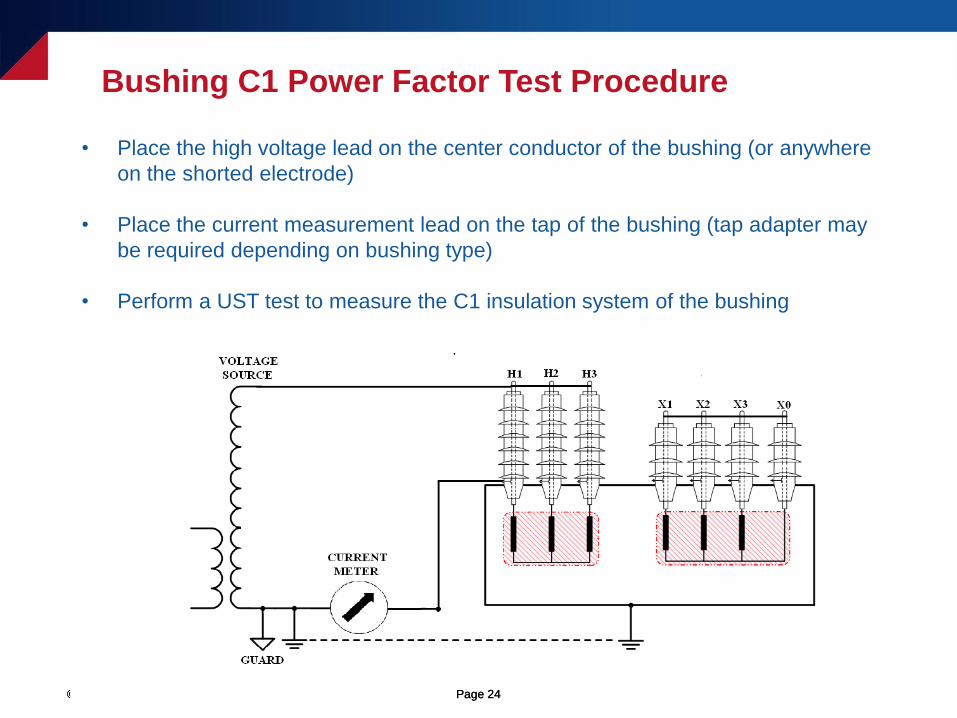
Bushing C1 Power Factor Test Procedure
• Place the high voltage lead on the center conductor of the bushing (or anywhere
on the shorted electrode)
• Place the current measurement lead on the tap of the bushing (tap adapter may
be required depending on bushing type)
• Perform a UST test to measure the C1 insulation system of the bushing
© OMICRON Page 25© OMICRON Page 25
Ca
CbCc
CdCe
Cf
Cg
Ch
Tap
Cen
ter
Co
nd
ucto
r
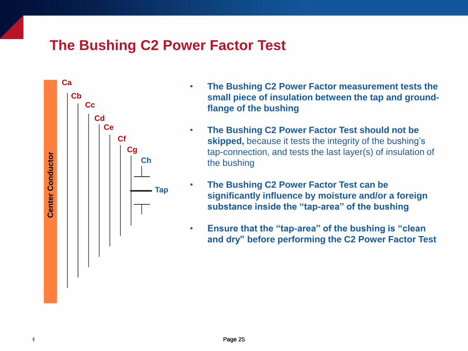
• The Bushing C2 Power Factor measurement tests the
small piece of insulation between the tap and ground-
flange of the bushing
• The Bushing C2 Power Factor Test should not be
skipped, because it tests the integrity of the bushing’s
tap-connection, and tests the last layer(s) of insulation of
the bushing
• The Bushing C2 Power Factor Test can be
significantly influence by moisture and/or a foreign
substance inside the “tap-area” of the bushing
• Ensure that the “tap-area” of the bushing is “clean
and dry” before performing the C2 Power Factor Test
The Bushing C2 Power Factor Test
© OMICRON Page 26© OMICRON Page 26
Bushing C2 Power Factor Test Procedure
Ca
CbCc
CdCe
Cf
Cg
Ch
Tap
Cen
ter
Co
nd
ucto
r
C1 Insulation C2 Insulation
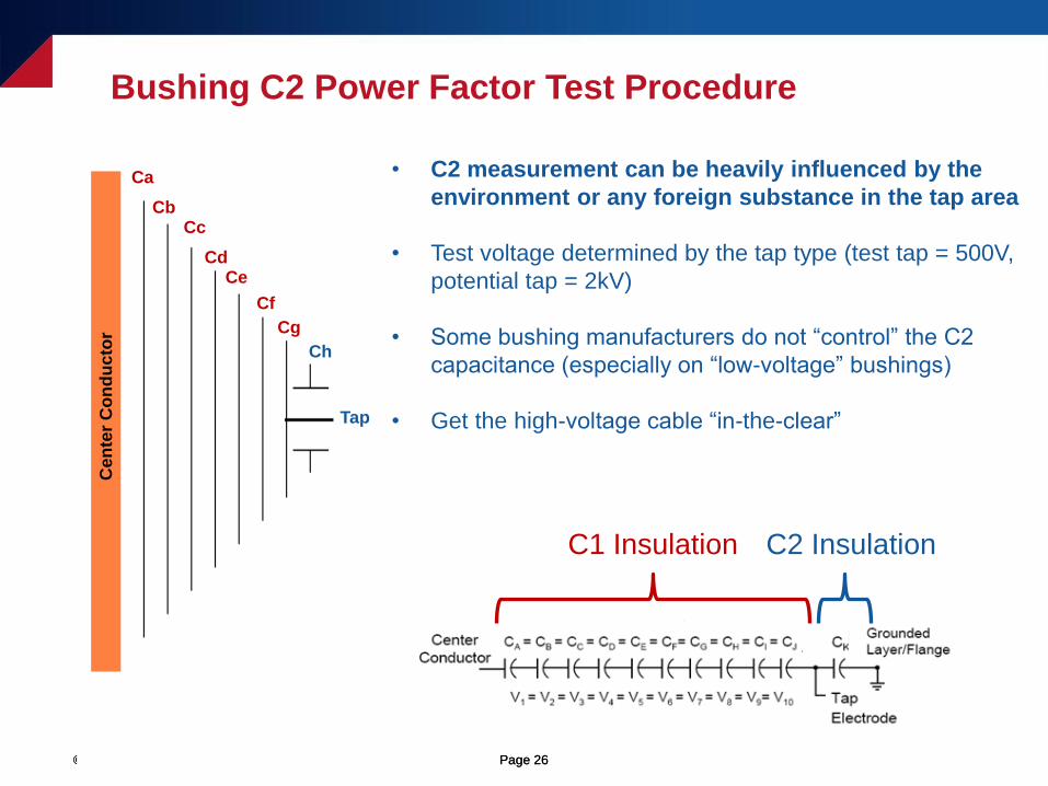
• C2 measurement can be heavily influenced by the
environment or any foreign substance in the tap area
• Test voltage determined by the tap type (test tap = 500V,
potential tap = 2kV)
• Some bushing manufacturers do not “control” the C2
capacitance (especially on “low-voltage” bushings)
• Get the high-voltage cable “in-the-clear”
© OMICRON Page 27© OMICRON Page 27
Bushing C2 Power Factor Test Procedure
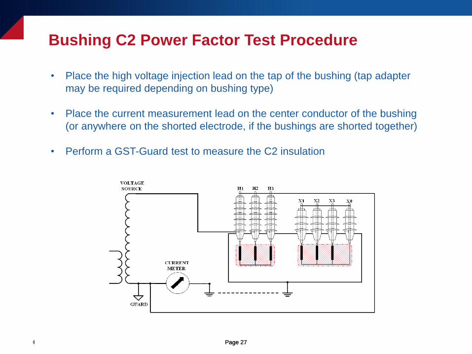
• Place the high voltage injection lead on the tap of the bushing (tap adapter
may be required depending on bushing type)
• Place the current measurement lead on the center conductor of the bushing
(or anywhere on the shorted electrode, if the bushings are shorted together)
• Perform a GST-Guard test to measure the C2 insulation
© OMICRON Page 28© OMICRON Page 28
Energized Collar/Hot Collar Test Overview
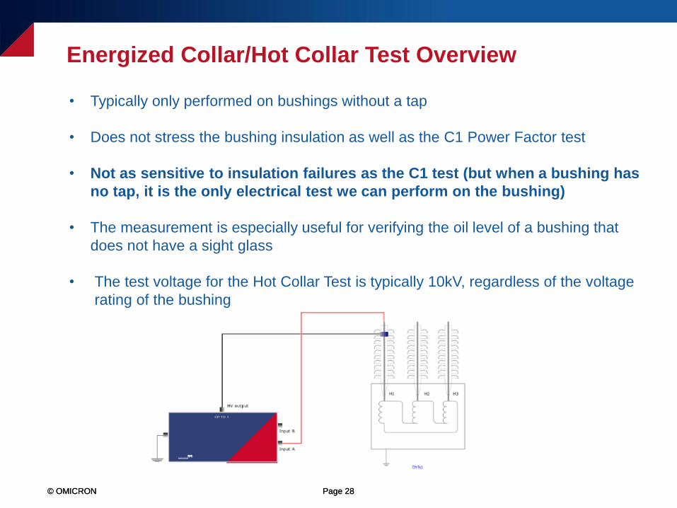
• Typically only performed on bushings without a tap
• Does not stress the bushing insulation as well as the C1 Power Factor test
• Not as sensitive to insulation failures as the C1 test (but when a bushing has
no tap, it is the only electrical test we can perform on the bushing)
• The measurement is especially useful for verifying the oil level of a bushing that
does not have a sight glass
• The test voltage for the Hot Collar Test is typically 10kV, regardless of the voltage
rating of the bushing
© OMICRON Page 29© OMICRON Page 29
Energized Collar/Hot Collar Test Overview
• The Hot Collar test essentially only tests the insulation near the area of
the collar
• Therefore, the collar may have to be moved around to different locations on a
bushing, to test the different sections of the bushing’s insulation system...
1) At the top of the bushing
2) In the middle of the bushing
3) At the bottom of the bushing
• The customer must weigh the diagnostic value against the amount of time it
takes to perform a thorough Hot Collar measurement, to determine if the
measurement is worthwhile
• One option could be to only perform the Hot Collar measurement when there
is a reason to suspect that there is a problem with the bushing (e.g. due to a
visual inspection or due to a higher than normal Overall PF measurement)
© OMICRON Page 30© OMICRON Page 30
• We typically do not assess the Power Factor value when performing the Hot
Collar Test (due to the relatively low capacitance of the measurement)
• We typically analyze the measured Current (mA) and Watts Loss (W)
• The industry accepted rule-of-thumb is that, if the measured Watts Loss is
below 0.1W, then the Hot Collar measurement is “acceptable”
• The measured Current and Watts Loss should also be reasonably similar to
any previous measurements performed on the same bushing
• The measured Current and Watts Loss should be reasonably similar when
comparing measurements amongst “sister unit” bushings
Energized Collar/Hot Collar Test Result Analysis
© OMICRON Page 31© OMICRON Page 31
Hot Collar Test - UST vs. GST Mode
• When using the UST test mode
1) Tests area under and near the hot collar strap
2) Tests the oil level of the bushing (if the strap is applied under the top
skirt of the bushing)
• When using the GST test mode
1) Tests area under and near the hot collar strap
2) Tests the oil level of the bushing (if the strap is applied under the top
skirt of the bushing)
3) May include leakage current across the surface of the bushing (which
could be due to a defect or due to the test environment)

© OMICRON Page 32© OMICRON Page 32
Bushing Investigation Tests
• Visual Inspection (check oil level, oil color, look for cracks, leaks, etc.)
• Power Factor Frequency Sweep Test (aka variable frequency power factor)
• Power Factor Voltage Sweep Test (aka “voltage tip-up test”)
• Overall Power Factor Test
• Inverted C1 Test
• C1+C2 Test
• Multiple Energized Collar Tests

© OMICRON Page 33
An Introduction to Performing Power Factor
Sweep Tests on Bushings
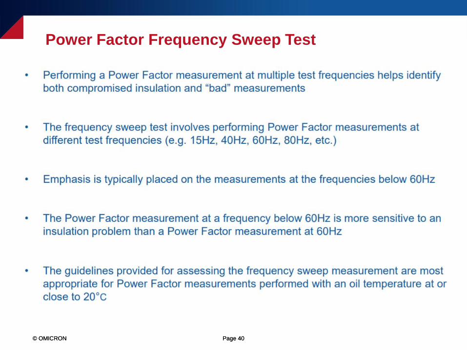
© OMICRON Page 34© OMICRON Page 34
Bushing Power Factor Sweep Overview

© OMICRON Page 35© OMICRON Page 35
Bushing Power Factor Sweep Overview
© OMICRON Page 36© OMICRON Page 36
Who Can Benefit from Performing the Sweep Measurements?
© OMICRON Page 37© OMICRON Page 37
Who Can Benefit from Performing the Sweep Measurements?
© OMICRON Page 38© OMICRON Page 38
Bushing Power Factor Sweep Analysis
© OMICRON Page 39© OMICRON Page 39
Power Factor Voltage Sweep Test (aka Voltage Tip-Up Test)
© OMICRON Page 40© OMICRON Page 40
Power Factor Frequency Sweep Test
© OMICRON Page 41© OMICRON Page 41
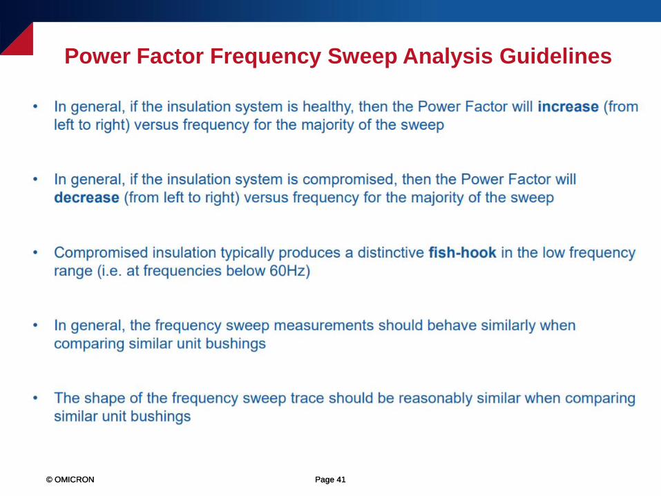
Power Factor Frequency Sweep Analysis Guidelines
© OMICRON Page 42© OMICRON Page 42
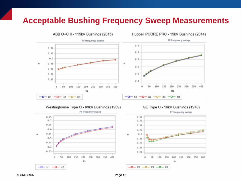
Acceptable Bushing Frequency Sweep Measurements

© OMICRON Page 43
Bushing Power Factor Test Analysis
© OMICRON Page 44© OMICRON Page 44
• Having previous test results to compare to is important and significantly helps
to assess the integrity of the bushing insulation system
• In general, if the Power Factor increases, then the insulation system has
deteriorated since the previous test date
• An “abnormally low” or negative Power Factor could also be an indication of
compromised insulation (typically, an “abnormally low” Power Factor value is
defined as less than 0.1%)
Bushing Power Factor Analysis – Time-Based Comparison
© OMICRON Page 45© OMICRON Page 45
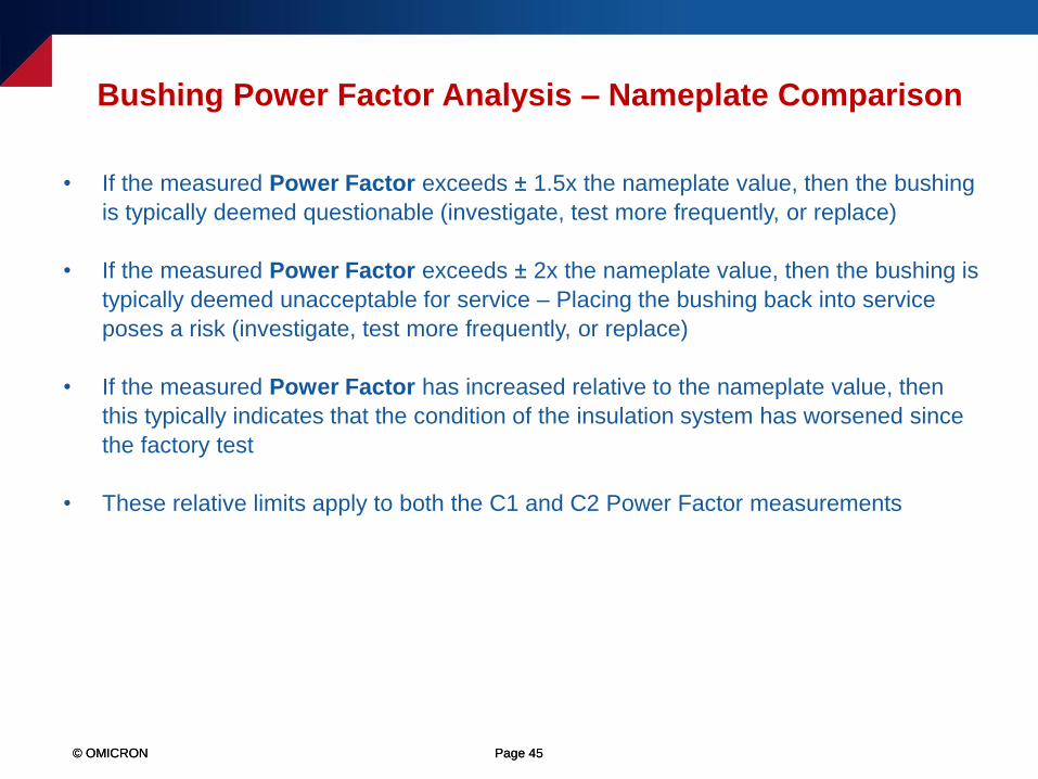
• If the measured Power Factor exceeds ± 1.5x the nameplate value, then the bushing
is typically deemed questionable (investigate, test more frequently, or replace)
• If the measured Power Factor exceeds ± 2x the nameplate value, then the bushing is
typically deemed unacceptable for service – Placing the bushing back into service
poses a risk (investigate, test more frequently, or replace)
• If the measured Power Factor has increased relative to the nameplate value, then
this typically indicates that the condition of the insulation system has worsened since
the factory test
• These relative limits apply to both the C1 and C2 Power Factor measurements
Bushing Power Factor Analysis – Nameplate Comparison
© OMICRON Page 46© OMICRON Page 46
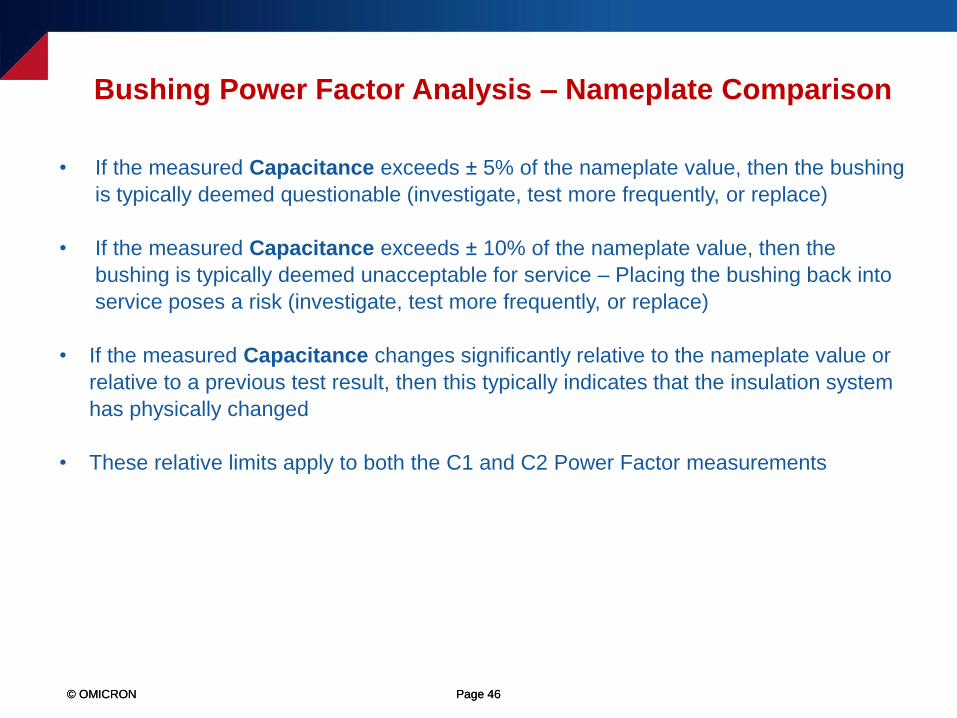
• If the measured Capacitance exceeds ± 5% of the nameplate value, then the bushing
is typically deemed questionable (investigate, test more frequently, or replace)
• If the measured Capacitance exceeds ± 10% of the nameplate value, then the
bushing is typically deemed unacceptable for service – Placing the bushing back into
service poses a risk (investigate, test more frequently, or replace)
• If the measured Capacitance changes significantly relative to the nameplate value or
relative to a previous test result, then this typically indicates that the insulation system
has physically changed
• These relative limits apply to both the C1 and C2 Power Factor measurements
Bushing Power Factor Analysis – Nameplate Comparison
© OMICRON Page 47© OMICRON Page 47
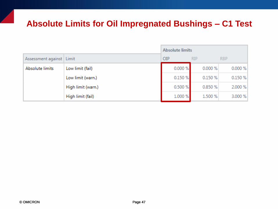
Absolute Limits for Oil Impregnated Bushings – C1 Test

© OMICRON Page 48© OMICRON Page 48
Absolute Limits for Resin Impregnated Bushings – C1 Test
© OMICRON Page 49© OMICRON Page 49
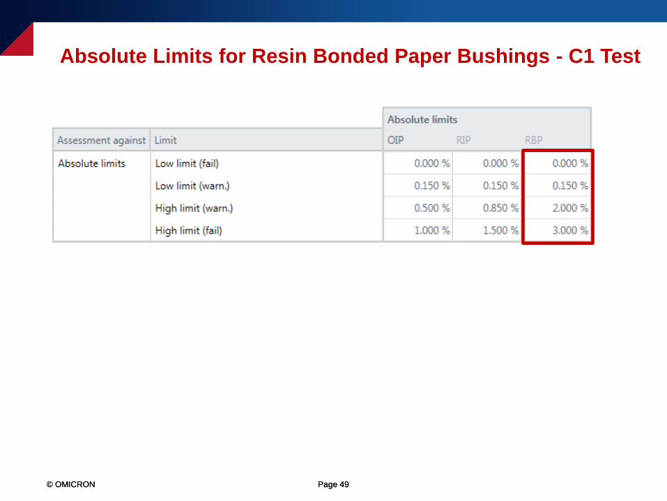
Absolute Limits for Resin Bonded Paper Bushings - C1 Test
© OMICRON Page 50© OMICRON Page 50
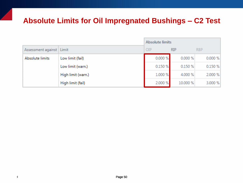
Absolute Limits for Oil Impregnated Bushings – C2 Test

© OMICRON Page 51© OMICRON Page 51
Absolute Limits for Resin Impregnated Bushings – C2 Test
© OMICRON Page 52© OMICRON Page 52
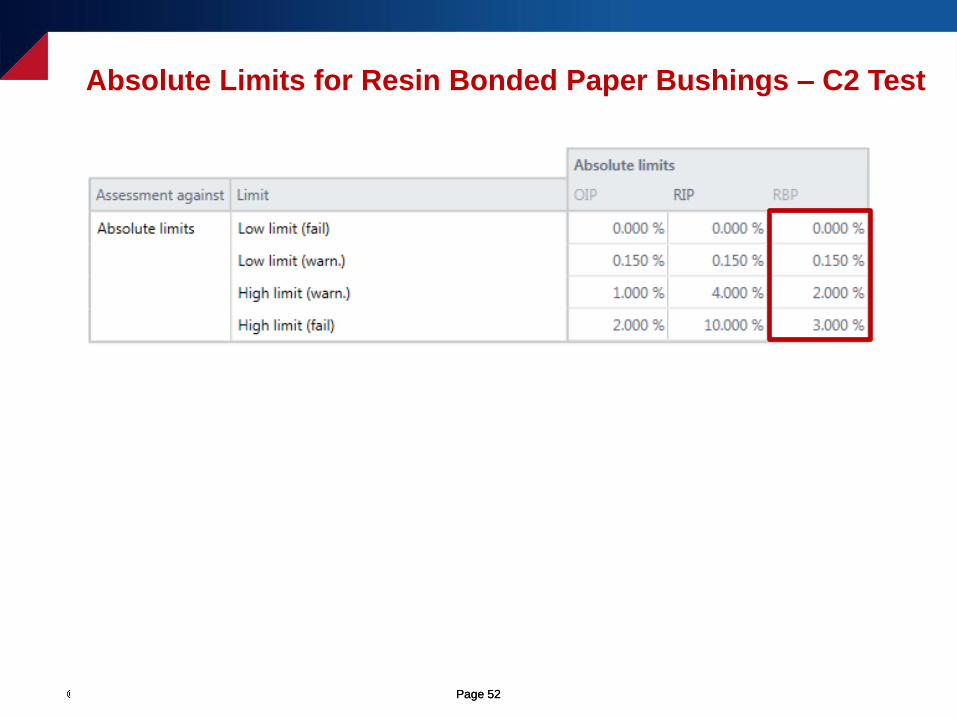
Absolute Limits for Resin Bonded Paper Bushings – C2 Test
© OMICRON Page 53© OMICRON
Abnormally Low or Negative Power Factor
• An “abnormally low” or negative Power Factor is typically caused by a high
resistive path to ground, which could be due to one of the following,
User error (e.g. a bad ground connection or a poor test connection)
Test environment – Moisture, high-humidity, rain, snow, cold temperatures, etc.
A test specimen that has a relatively low Capacitance value (typically defined
as less than 80pF)
A loose or poorly connected bushing ground flange (typically only relevant
when performing the C1 and C2 Power Factor measurements)
Compromised insulation
© OMICRON Page 54
Bushing C1 Power Factor Test Examples
© OMICRON Page 55© OMICRON Page 55
Questionable Bushing C1 Power Factor Measurements
© OMICRON Page 56© OMICRON Page 56
Questionable Bushing C1 Power Factor Measurements
© OMICRON Page 57© OMICRON Page 57
Questionable Bushing C1 Power Factor Measurements
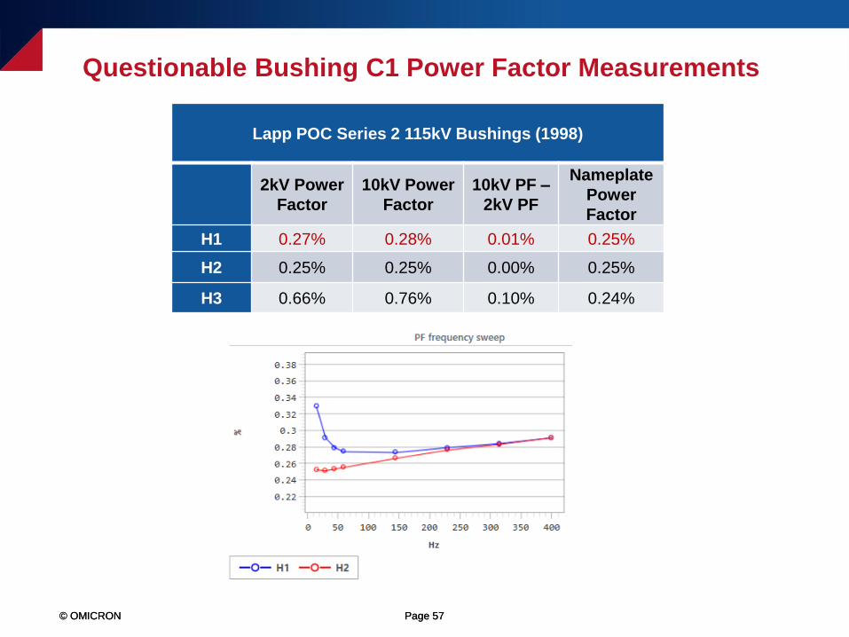
Lapp POC Series 2 115kV Bushings (1998)
2kV Power
Factor
10kV Power
Factor
10kV PF –
2kV PF
Nameplate
Power
Factor
H1 0.27% 0.28% 0.01% 0.25%
H2 0.25% 0.25% 0.00% 0.25%
H3 0.66% 0.76% 0.10% 0.24%
© OMICRON Page 58© OMICRON Page 58
Questionable Bushing C1 Power Factor Measurements
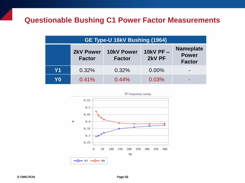
GE Type-U 16kV Bushing (1964)
2kV Power
Factor
10kV Power
Factor
10kV PF –
2kV PF
Nameplate
Power
Factor
Y1 0.32% 0.32% 0.00% -
Y0 0.41% 0.44% 0.03% -

© OMICRON Page 59© OMICRON Page 59
Questionable Bushing C1 Power Factor Measurements
Westinghouse Electric Type S 37kV Bushings
2kV Power
Factor
10kV Power
Factor
10kV PF –
2kV PF
Nameplate
Power
Factor
Measured
Capacitance
Nameplate
Capacitance
H1 0.60% 0.58% -0.02% 0.65% 169pF 182pF
H2 0.79% 0.78% -0.01% 0.72% 184pF 197pF
H3 0.69% 0.69% 0.00% 0.66% 203pF 198pF
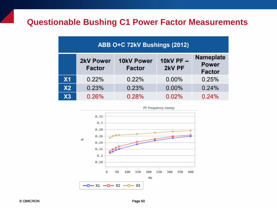
© OMICRON Page 60© OMICRON Page 60
Questionable Bushing C1 Power Factor Measurements
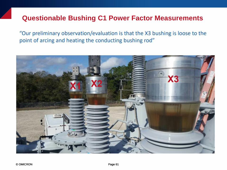
© OMICRON Page 61© OMICRON Page 61
Questionable Bushing C1 Power Factor Measurements
© OMICRON Page 62© OMICRON Page 62
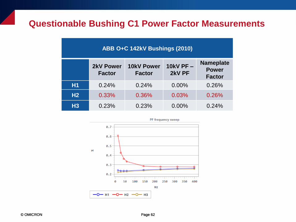
Questionable Bushing C1 Power Factor Measurements
ABB O+C 142kV Bushings (2010)
2kV Power
Factor
10kV Power
Factor
10kV PF –
2kV PF
Nameplate
Power
Factor
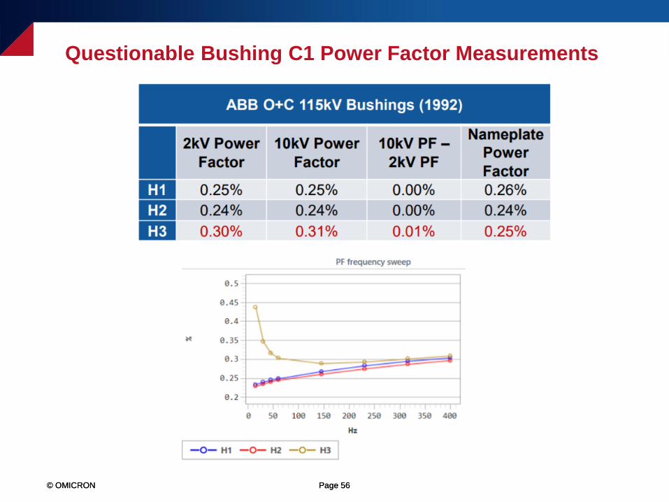
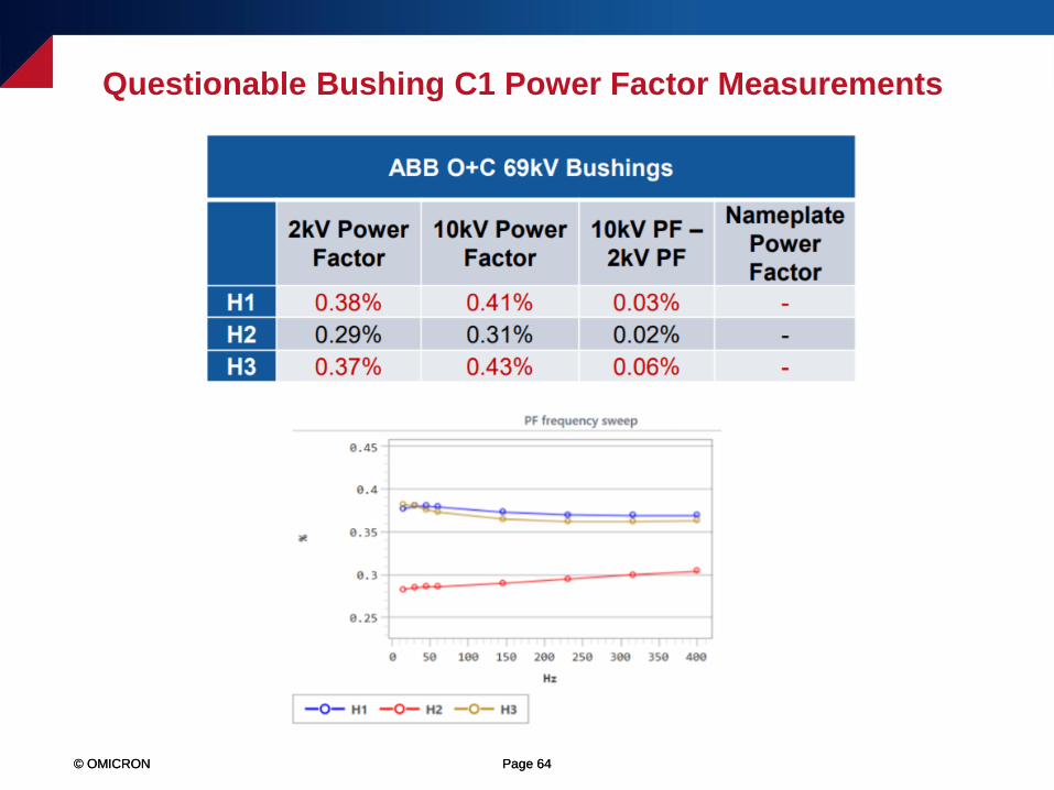
H1 0.24% 0.24% 0.00% 0.26%
H2 0.33% 0.36% 0.03% 0.26%
H3 0.23% 0.23% 0.00% 0.24%
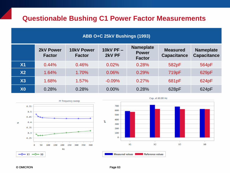
© OMICRON Page 63© OMICRON Page 63
Questionable Bushing C1 Power Factor Measurements
ABB O+C 25kV Bushings (1993)
2kV Power
Factor
10kV Power
Factor
10kV PF –
2kV PF
Nameplate
Power
Factor
Measured
Capacitance
Nameplate
Capacitance
X1 0.44% 0.46% 0.02% 0.28% 582pF 564pF
X2 1.64% 1.70% 0.06% 0.29% 719pF 629pF
X3 1.68% 1.57% -0.09% 0.27% 681pF 624pF
X0 0.28% 0.28% 0.00% 0.28% 628pF 624pF
© OMICRON Page 64© OMICRON Page 64
Questionable Bushing C1 Power Factor Measurements
© OMICRON Page 65© OMICRON Page 65
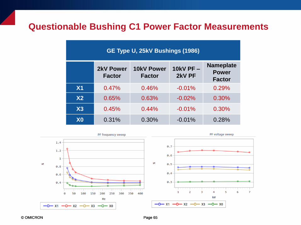
Questionable Bushing C1 Power Factor Measurements
GE Type U, 25kV Bushings (1986)
2kV Power
Factor
10kV Power
Factor
10kV PF –
2kV PF
Nameplate
Power
Factor
X1 0.47% 0.46% -0.01% 0.29%
X2 0.65% 0.63% -0.02% 0.30%
X3 0.45% 0.44% -0.01% 0.30%
X0 0.31% 0.30% -0.01% 0.28%

© OMICRON Page 66© OMICRON Page 66
Questionable Bushing C1 Power Factor Measurements
GE Type U 27.5kV Bushings (1984)
2kV Power
Factor
10kV Power
Factor
10kV PF –
2kV PF
Nameplate
Power
Factor
S1 0.30% 0.32% 0.02% 0.27%
S2 0.28% 0.28% 0.00% 0.31%
S3 0.27% 0.27% 0.00% 0.30%
S0L0 0.29% 0.29% 0.00% 0.33%
© OMICRON Page 67© OMICRON Page 67
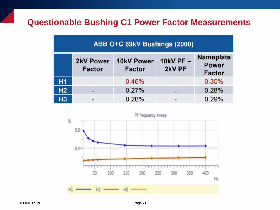
Questionable Bushing C1 Power Factor Measurements
© OMICRON Page 68© OMICRON Page 68
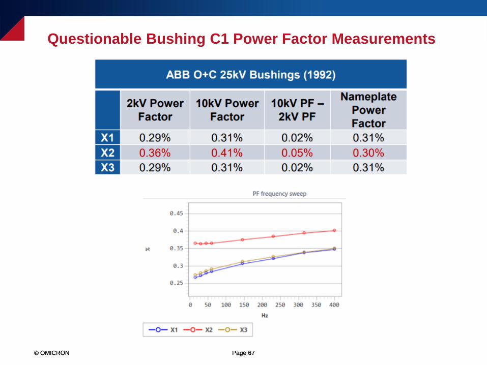
Questionable Bushing C1 Power Factor Measurements
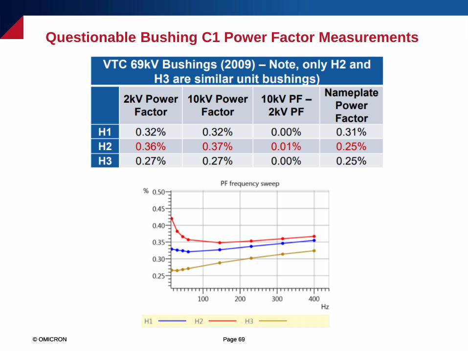
© OMICRON Page 69© OMICRON Page 69
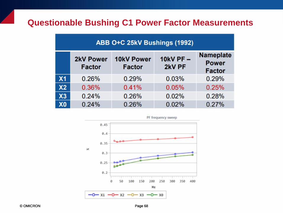
Questionable Bushing C1 Power Factor Measurements
© OMICRON Page 70© OMICRON Page 70
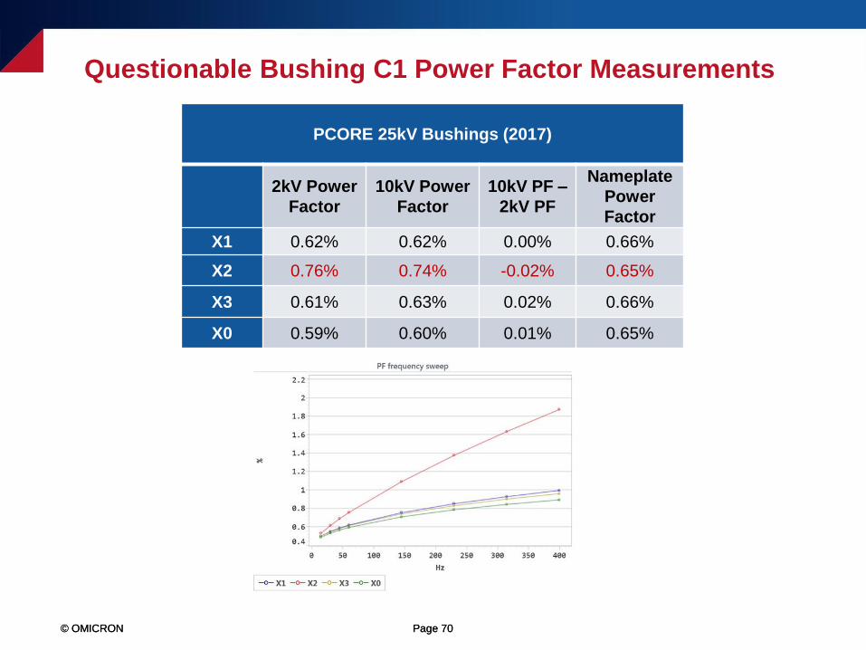
Questionable Bushing C1 Power Factor Measurements
PCORE 25kV Bushings (2017)
2kV Power
Factor
10kV Power
Factor
10kV PF –
2kV PF
Nameplate
Power
Factor
X1 0.62% 0.62% 0.00% 0.66%
X2 0.76% 0.74% -0.02% 0.65%
X3 0.61% 0.63% 0.02% 0.66%
X0 0.59% 0.60% 0.01% 0.65%
© OMICRON Page 71© OMICRON Page 71
Questionable Bushing C1 Power Factor Measurements
© OMICRON Page 72© OMICRON Page 72
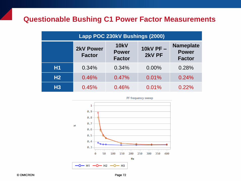
Questionable Bushing C1 Power Factor Measurements
Lapp POC 230kV Bushings (2000)
2kV Power
Factor
10kV
Power
Factor
10kV PF –
2kV PF
Nameplate
Power
Factor
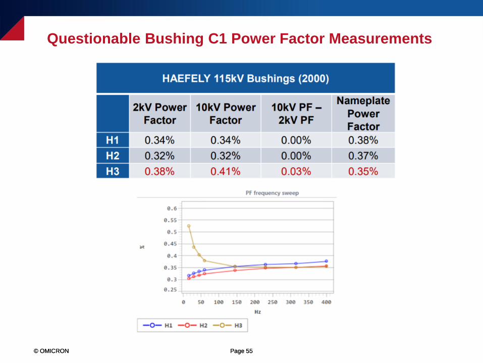
H1 0.34% 0.34% 0.00% 0.28%
H2 0.46% 0.47% 0.01% 0.24%
H3 0.45% 0.46% 0.01% 0.22%
© OMICRON Page 73© OMICRON Page 73
Questionable Bushing C1 Power Factor Measurements

© OMICRON Page 74© OMICRON Page 74
Questionable Bushing C1 Power Factor Measurements

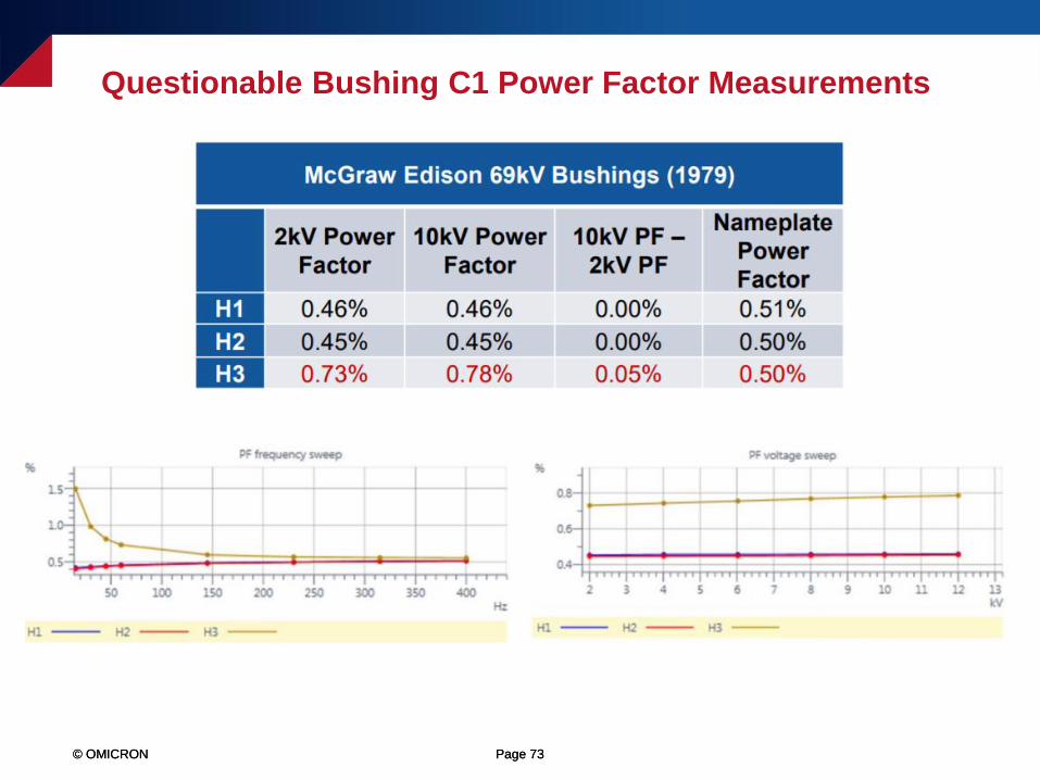
© OMICRON Page 75© OMICRON Page 75
Questionable Bushing C1 Power Factor Measurements
Lapp POC Series 2 115kV Bushings (1998)
2kV Power
Factor
10kV Power
Factor
10kV PF –
2kV PF
Nameplate
Power
Factor
H1 0.27% 0.28% 0.01% 0.25%
H2 0.25% 0.25% 0.00% 0.25%
H3 0.66% 0.76% 0.10% 0.24%
© OMICRON Page 76© OMICRON Page 76
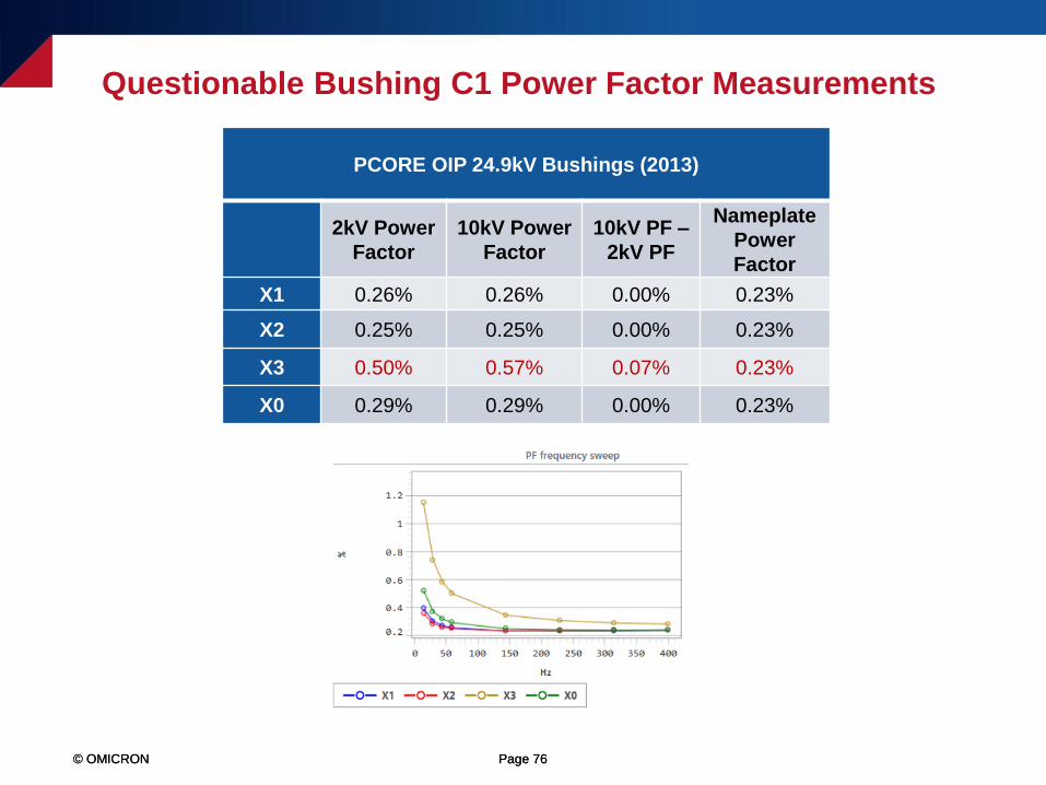
Questionable Bushing C1 Power Factor Measurements
PCORE OIP 24.9kV Bushings (2013)
2kV Power
Factor
10kV Power
Factor
10kV PF –
2kV PF
Nameplate
Power
Factor
X1 0.26% 0.26% 0.00% 0.23%
X2 0.25% 0.25% 0.00% 0.23%
X3 0.50% 0.57% 0.07% 0.23%
X0 0.29% 0.29% 0.00% 0.23%

© OMICRON Page 77© OMICRON Page 77
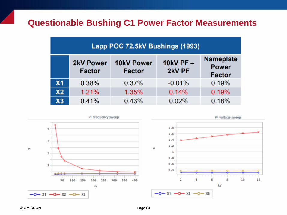
Questionable Bushing C1 Power Factor Measurements
© OMICRON Page 78© OMICRON Page 78
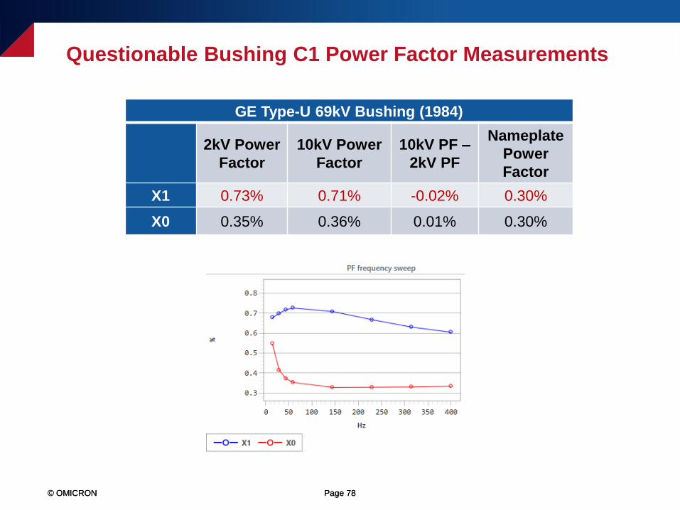
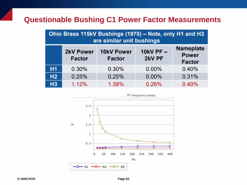
Questionable Bushing C1 Power Factor Measurements
GE Type-U 69kV Bushing (1984)
2kV Power
Factor
10kV Power
Factor
10kV PF –
2kV PF
Nameplate
Power
Factor
X1 0.73% 0.71% -0.02% 0.30%
X0 0.35% 0.36% 0.01% 0.30%
© OMICRON Page 79© OMICRON Page 79
Questionable Bushing C1 Power Factor Measurements
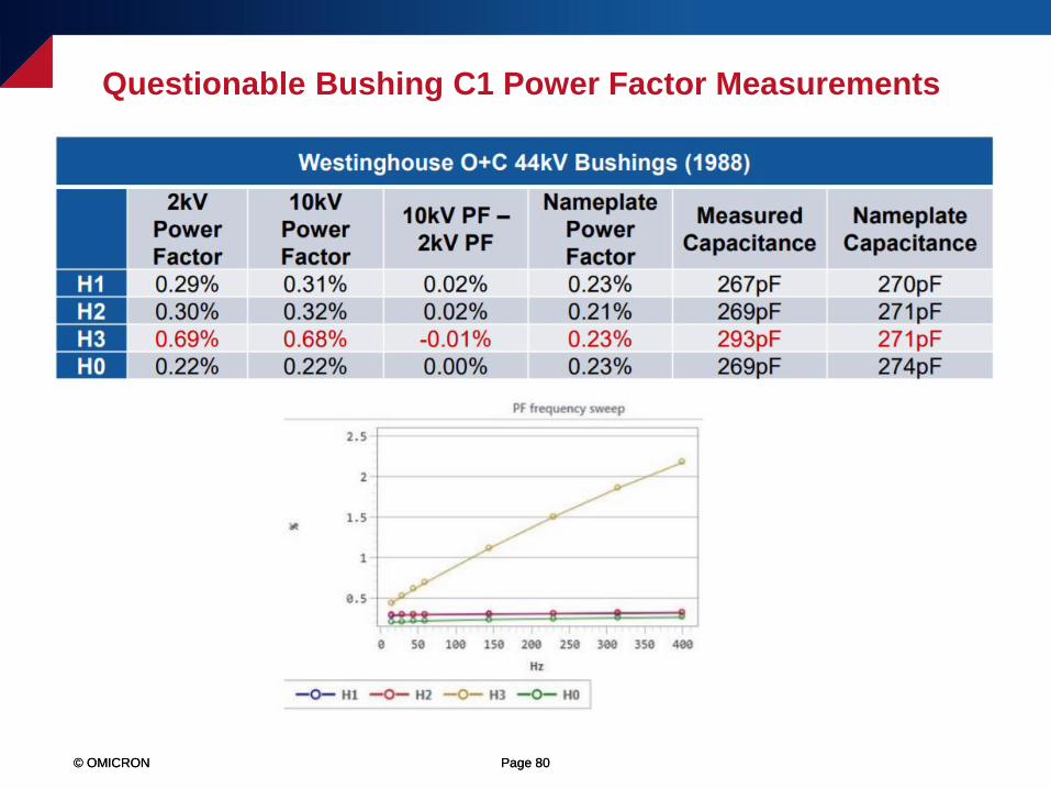
© OMICRON Page 80© OMICRON Page 80
Questionable Bushing C1 Power Factor Measurements

© OMICRON Page 81© OMICRON Page 81
Questionable Bushing C1 Power Factor Measurements
ABB O+C 25kV Bushings (1993)
2kV Power
Factor
10kV Power
Factor
10kV PF –
2kV PF
Nameplate
Power
Factor
Measured
Capacitance
Nameplate
Capacitance
X1 0.44% 0.46% 0.02% 0.28% 582pF 564pF
X2 1.64% 1.70% 0.06% 0.29% 719pF 629pF
X3 1.68% 1.57% -0.09% 0.27% 681pF 624pF
X0 0.28% 0.28% 0.00% 0.28% 628pF 624pF
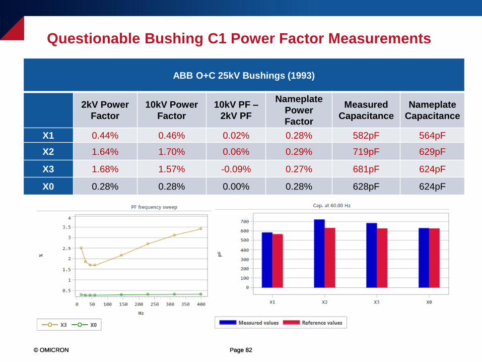
© OMICRON Page 82© OMICRON Page 82
Questionable Bushing C1 Power Factor Measurements
ABB O+C 25kV Bushings (1993)
2kV Power
Factor
10kV Power
Factor
10kV PF –
2kV PF
Nameplate
Power
Factor
Measured
Capacitance
Nameplate
Capacitance
X1 0.44% 0.46% 0.02% 0.28% 582pF 564pF
X2 1.64% 1.70% 0.06% 0.29% 719pF 629pF
X3 1.68% 1.57% -0.09% 0.27% 681pF 624pF
X0 0.28% 0.28% 0.00% 0.28% 628pF 624pF
© OMICRON Page 83© OMICRON Page 83
Questionable Bushing C1 Power Factor Measurements
© OMICRON Page 84© OMICRON Page 84
Questionable Bushing C1 Power Factor Measurements
© OMICRON Page 85
Using the Power Factor Sweep Tests to Identify
Invalid Bushing Measurements
© OMICRON Page 86© OMICRON Page 86
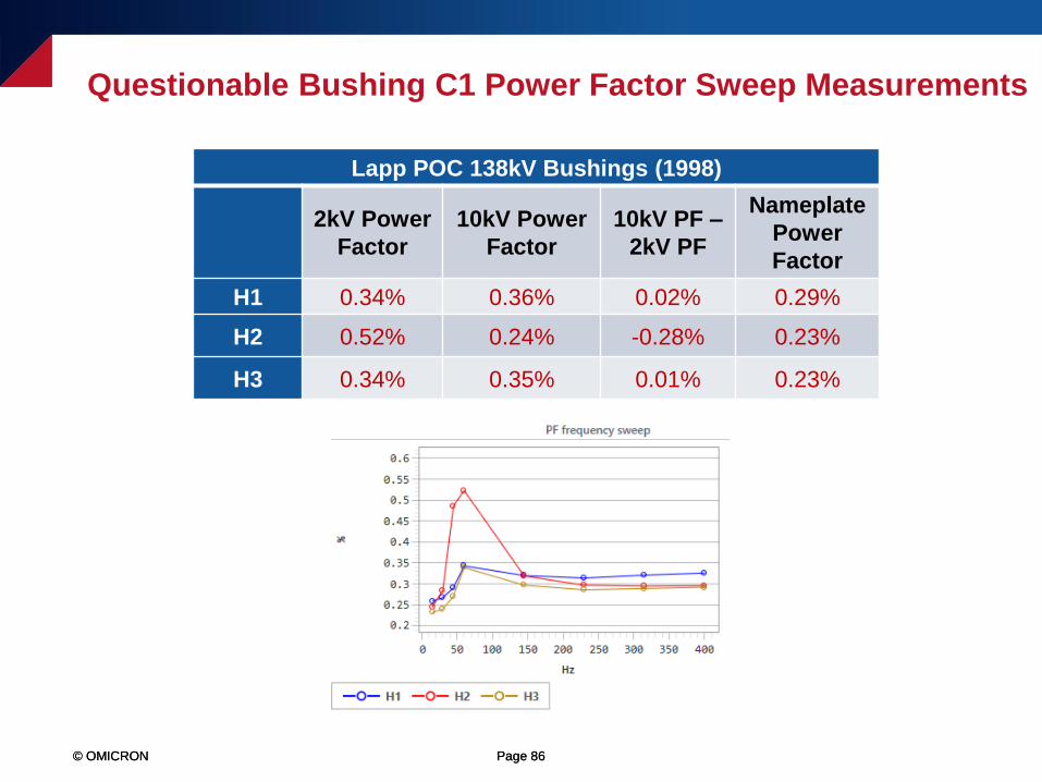
Questionable Bushing C1 Power Factor Sweep Measurements
Lapp POC 138kV Bushings (1998)
2kV Power
Factor
10kV Power
Factor
10kV PF –
2kV PF
Nameplate
Power
Factor
H1 0.34% 0.36% 0.02% 0.29%
H2 0.52% 0.24% -0.28% 0.23%
H3 0.34% 0.35% 0.01% 0.23%
© OMICRON Page 87© OMICRON Page 87
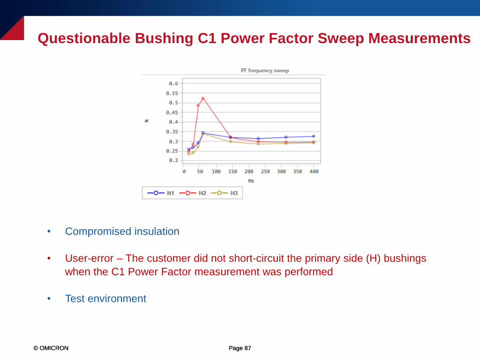
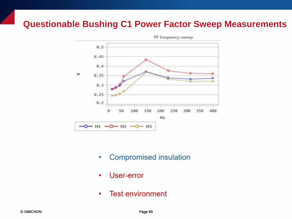
Questionable Bushing C1 Power Factor Sweep Measurements
• Compromised insulation
• User-error – The customer did not short-circuit the primary side (H) bushings
when the C1 Power Factor measurement was performed
• Test environment
© OMICRON Page 88© OMICRON Page 88
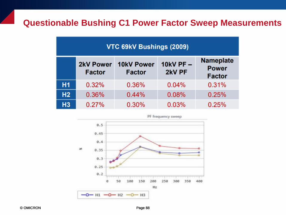
Questionable Bushing C1 Power Factor Sweep Measurements
© OMICRON Page 89© OMICRON Page 89
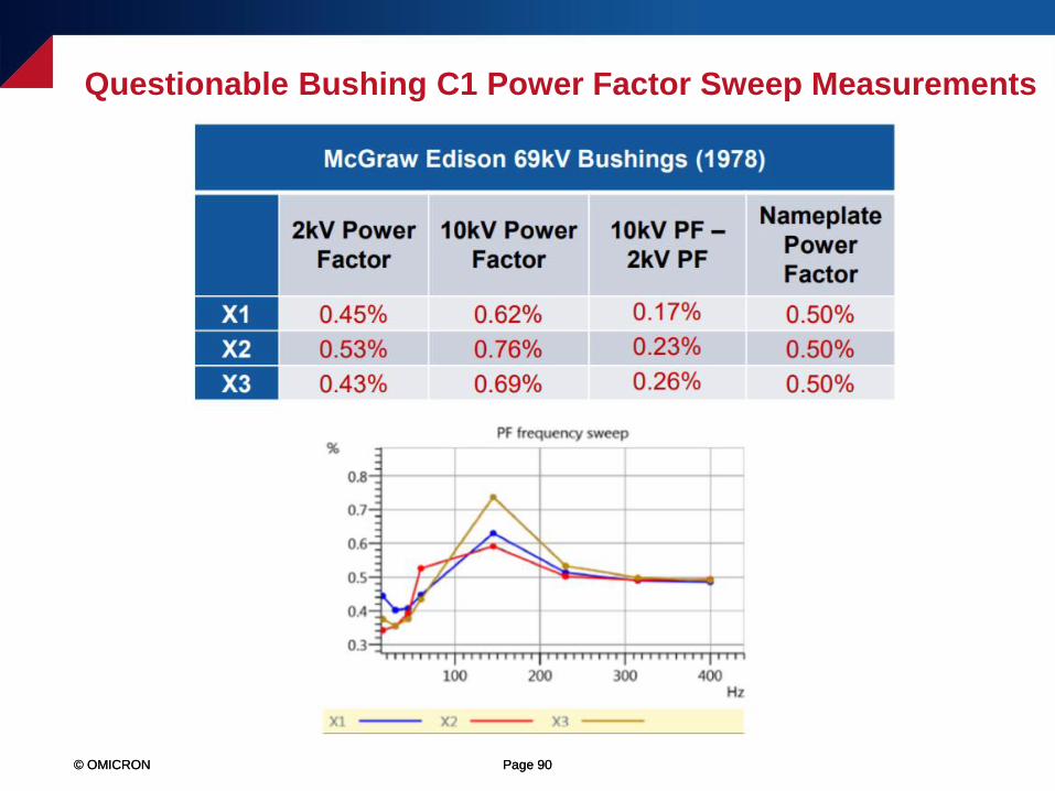
Questionable Bushing C1 Power Factor Sweep Measurements
© OMICRON Page 90© OMICRON Page 90
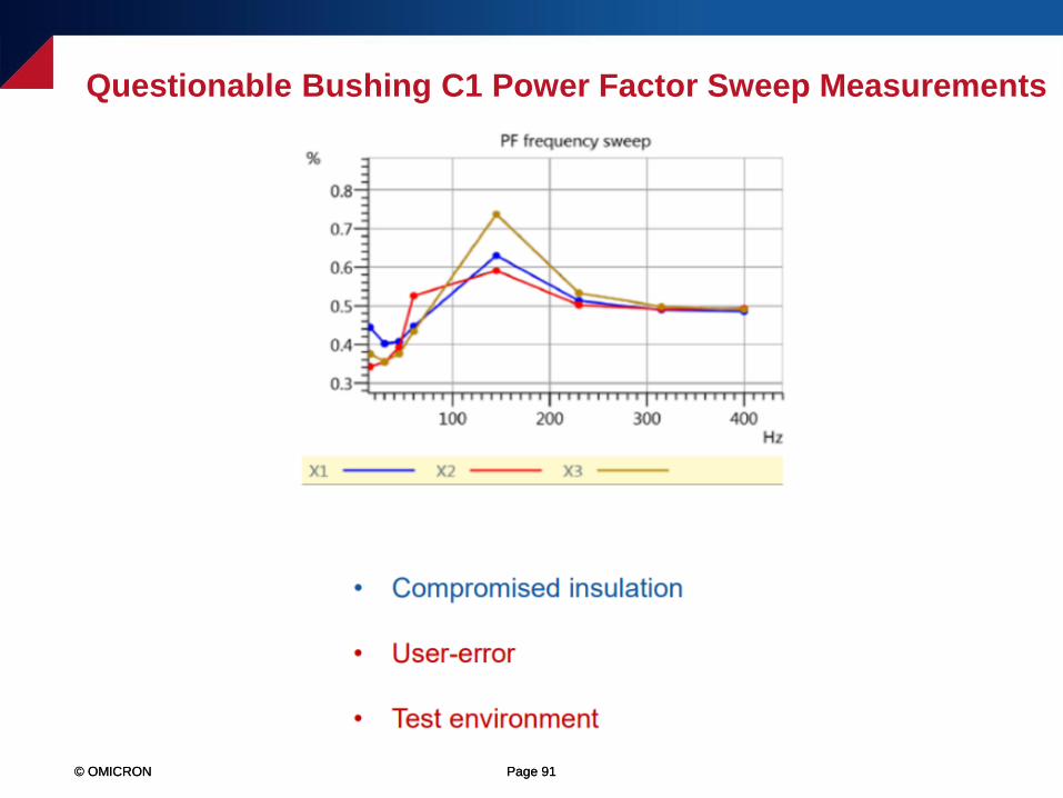
Questionable Bushing C1 Power Factor Sweep Measurements
© OMICRON Page 91© OMICRON Page 91
Questionable Bushing C1 Power Factor Sweep Measurements

© OMICRON Page 92© OMICRON Page 92
Questionable Bushing C1 Power Factor Sweep Measurements

© OMICRON Page 93© OMICRON Page 93
Questionable Bushing C1 Power Factor Sweep Measurements
© OMICRON Page 94© OMICRON Page 94
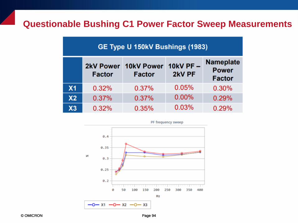
Questionable Bushing C1 Power Factor Sweep Measurements
© OMICRON Page 95© OMICRON Page 95
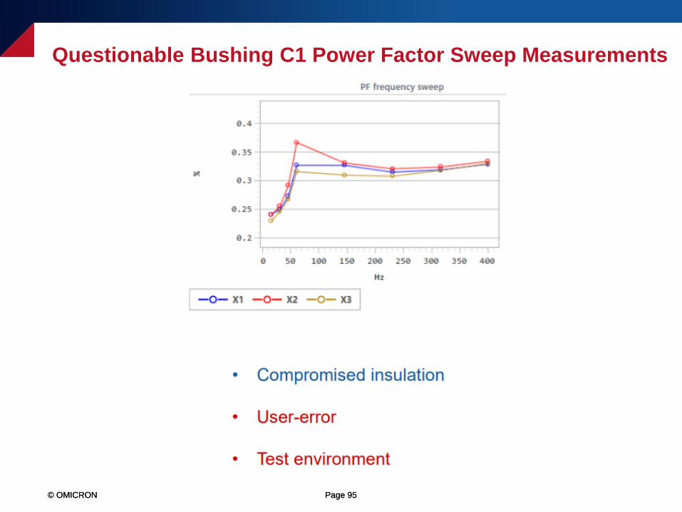
Questionable Bushing C1 Power Factor Sweep Measurements
© OMICRON Page 96© OMICRON Page 96
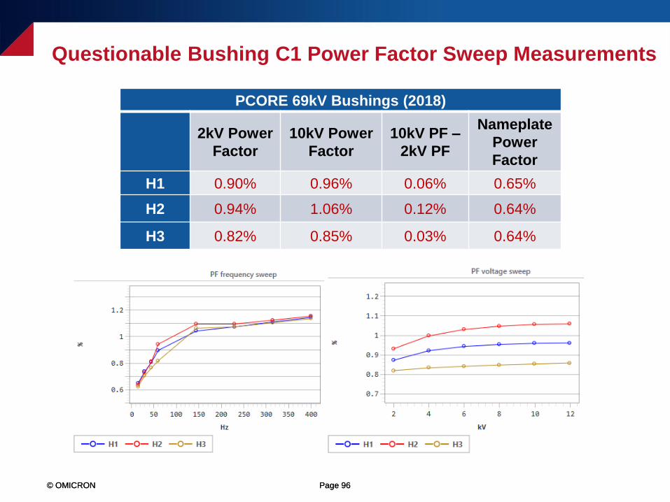
Questionable Bushing C1 Power Factor Sweep Measurements
PCORE 69kV Bushings (2018)
2kV Power
Factor
10kV Power
Factor
10kV PF –
2kV PF
Nameplate
Power
Factor
H1 0.90% 0.96% 0.06% 0.65%
H2 0.94% 1.06% 0.12% 0.64%
H3 0.82% 0.85% 0.03% 0.64%
© OMICRON Page 97© OMICRON Page 97
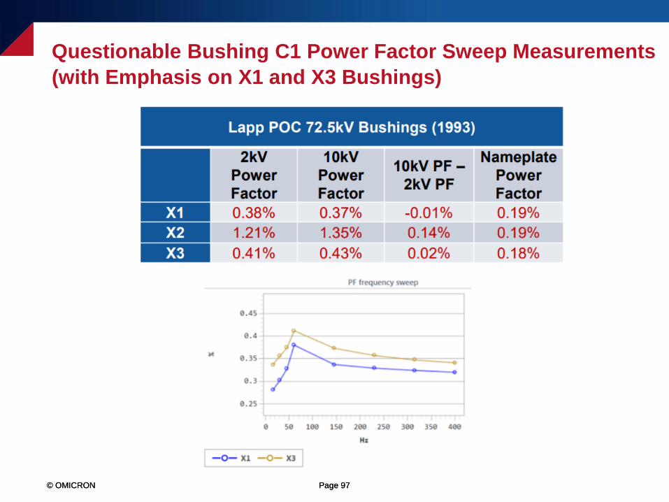
Questionable Bushing C1 Power Factor Sweep Measurements
(with Emphasis on X1 and X3 Bushings)
© OMICRON Page 98© OMICRON Page 98
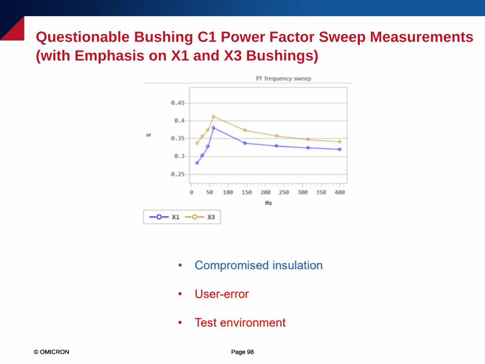
Questionable Bushing C1 Power Factor Sweep Measurements
(with Emphasis on X1 and X3 Bushings)
© OMICRON Page 99© OMICRON Page 99
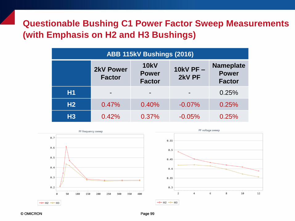
Questionable Bushing C1 Power Factor Sweep Measurements
(with Emphasis on H2 and H3 Bushings)
ABB 115kV Bushings (2016)
2kV Power
Factor
10kV
Power
Factor
10kV PF –
2kV PF
Nameplate
Power
Factor
H1 - - - 0.25%
H2 0.47% 0.40% -0.07% 0.25%
H3 0.42% 0.37% -0.05% 0.25%

© OMICRON Page 100
Bushing C2 Power Factor Test Examples
© OMICRON Page 101© OMICRON Page 101
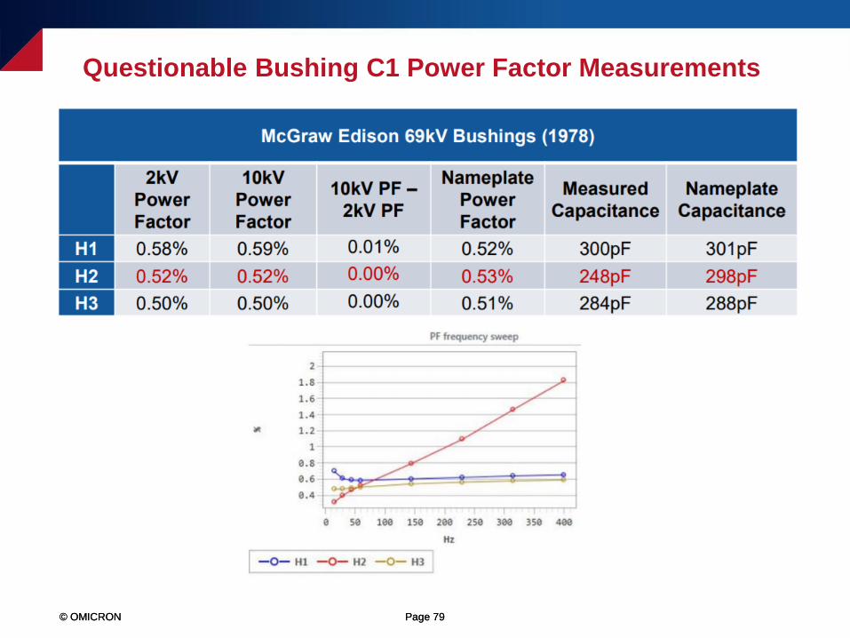
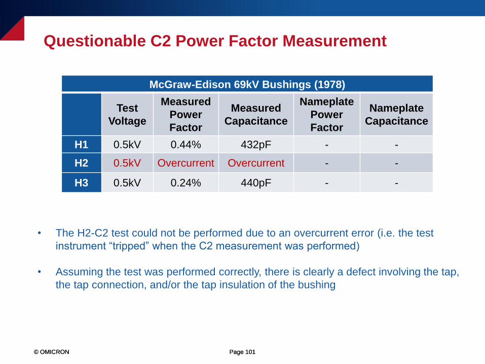
• The H2-C2 test could not be performed due to an overcurrent error (i.e. the test
instrument “tripped” when the C2 measurement was performed)
• Assuming the test was performed correctly, there is clearly a defect involving the tap,
the tap connection, and/or the tap insulation of the bushing
Questionable C2 Power Factor Measurement
McGraw-Edison 69kV Bushings (1978)
Test
Voltage
Measured
Power
Factor
Measured
Capacitance
Nameplate
Power
Factor
Nameplate
Capacitance
H1 0.5kV 0.44% 432pF - -
H2 0.5kV Overcurrent Overcurrent - -
H3 0.5kV 0.24% 440pF - -
© OMICRON Page 102© OMICRON Page 102
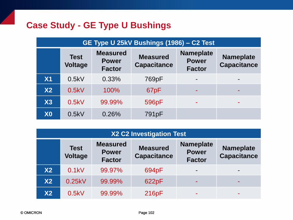
Case Study - GE Type U Bushings
GE Type U 25kV Bushings (1986) – C2 Test
Test
Voltage
Measured
Power
Factor
Measured
Capacitance
Nameplate
Power
Factor
Nameplate
Capacitance
X1 0.5kV 0.33% 769pF - -
X2 0.5kV 100% 67pF - -
X3 0.5kV 99.99% 596pF - -
X0 0.5kV 0.26% 791pF
X2 C2 Investigation Test
Test
Voltage
Measured
Power
Factor
Measured
Capacitance
Nameplate
Power
Factor
Nameplate
Capacitance
X2 0.1kV 99.97% 694pF - -
X2 0.25kV 99.99% 622pF - -
X2 0.5kV 99.99% 216pF - -
© OMICRON Page 103© OMICRON Page 103
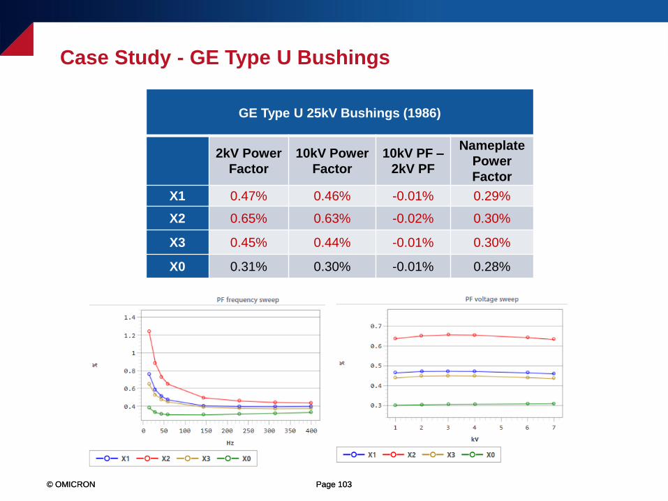
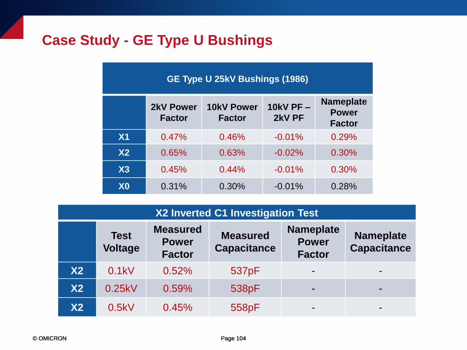
GE Type U 25kV Bushings (1986)
2kV Power
Factor
10kV Power
Factor
10kV PF –
2kV PF
Nameplate
Power
Factor
X1 0.47% 0.46% -0.01% 0.29%
X2 0.65% 0.63% -0.02% 0.30%
X3 0.45% 0.44% -0.01% 0.30%
X0 0.31% 0.30% -0.01% 0.28%
Case Study - GE Type U Bushings
© OMICRON Page 104© OMICRON Page 104
GE Type U 25kV Bushings (1986)
2kV Power
Factor
10kV Power
Factor
10kV PF –
2kV PF
Nameplate
Power
Factor
X1 0.47% 0.46% -0.01% 0.29%
X2 0.65% 0.63% -0.02% 0.30%
X3 0.45% 0.44% -0.01% 0.30%
X0 0.31% 0.30% -0.01% 0.28%
X2 Inverted C1 Investigation Test
Test
Voltage
Measured
Power
Factor
Measured
Capacitance
Nameplate
Power
Factor
Nameplate
Capacitance
X2 0.1kV 0.52% 537pF - -
X2 0.25kV 0.59% 538pF - -
X2 0.5kV 0.45% 558pF - -
Case Study - GE Type U Bushings
© OMICRON Page 105© OMICRON Page 105
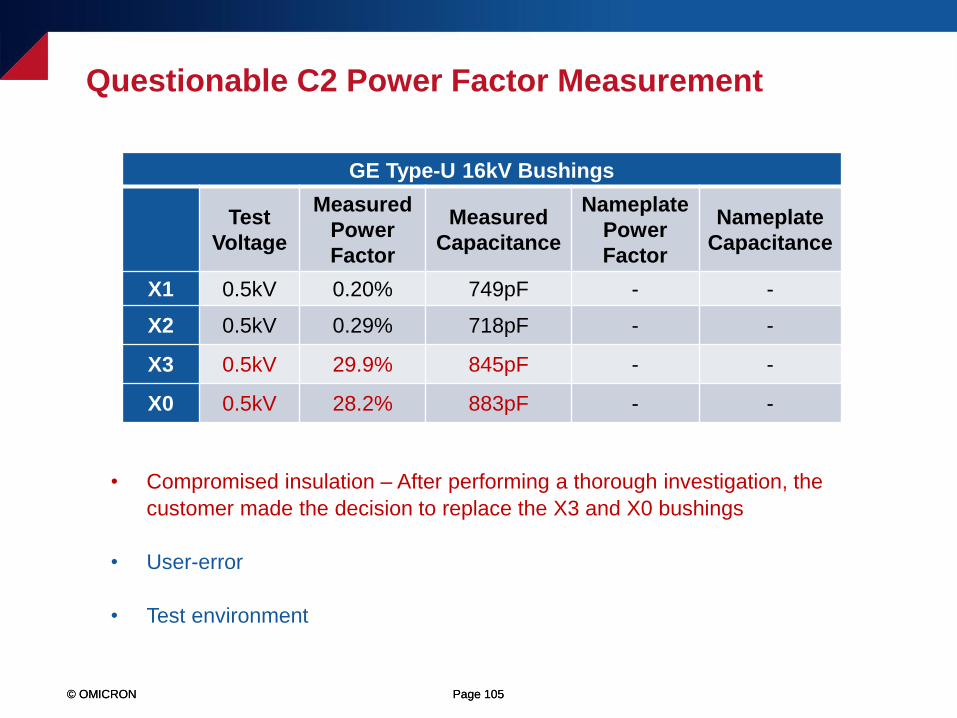
• Compromised insulation – After performing a thorough investigation, the
customer made the decision to replace the X3 and X0 bushings
• User-error
• Test environment
GE Type-U 16kV Bushings
Test
Voltage
Measured
Power
Factor
Measured
Capacitance
Nameplate
Power
Factor
Nameplate
Capacitance
X1 0.5kV 0.20% 749pF - -
X2 0.5kV 0.29% 718pF - -
X3 0.5kV 29.9% 845pF - -
X0 0.5kV 28.2% 883pF - -
Questionable C2 Power Factor Measurement
© OMICRON Page 106© OMICRON Page 106
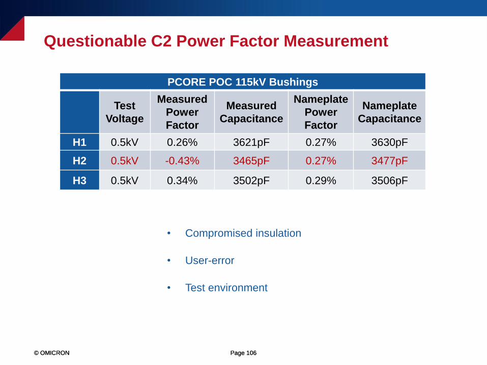
PCORE POC 115kV Bushings
Test
Voltage
Measured
Power
Factor
Measured
Capacitance
Nameplate
Power
Factor
Nameplate
Capacitance
H1 0.5kV 0.26% 3621pF 0.27% 3630pF
H2 0.5kV -0.43% 3465pF 0.27% 3477pF
H3 0.5kV 0.34% 3502pF 0.29% 3506pF
• Compromised insulation
• User-error
• Test environment
Questionable C2 Power Factor Measurement
© OMICRON Page 107© OMICRON Page 107
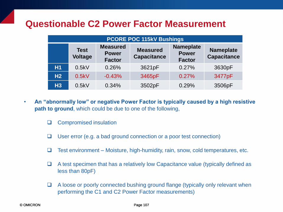
PCORE POC 115kV Bushings
Test
Voltage
Measured
Power
Factor
Measured
Capacitance
Nameplate
Power
Factor
Nameplate
Capacitance
H1 0.5kV 0.26% 3621pF 0.27% 3630pF
H2 0.5kV -0.43% 3465pF 0.27% 3477pF
H3 0.5kV 0.34% 3502pF 0.29% 3506pF
• An “abnormally low” or negative Power Factor is typically caused by a high resistive
path to ground, which could be due to one of the following,
Compromised insulation
User error (e.g. a bad ground connection or a poor test connection)
Test environment – Moisture, high-humidity, rain, snow, cold temperatures, etc.
A test specimen that has a relatively low Capacitance value (typically defined as
less than 80pF)
A loose or poorly connected bushing ground flange (typically only relevant when
performing the C1 and C2 Power Factor measurements)
Questionable C2 Power Factor Measurement
© OMICRON Page 108© OMICRON Page 108
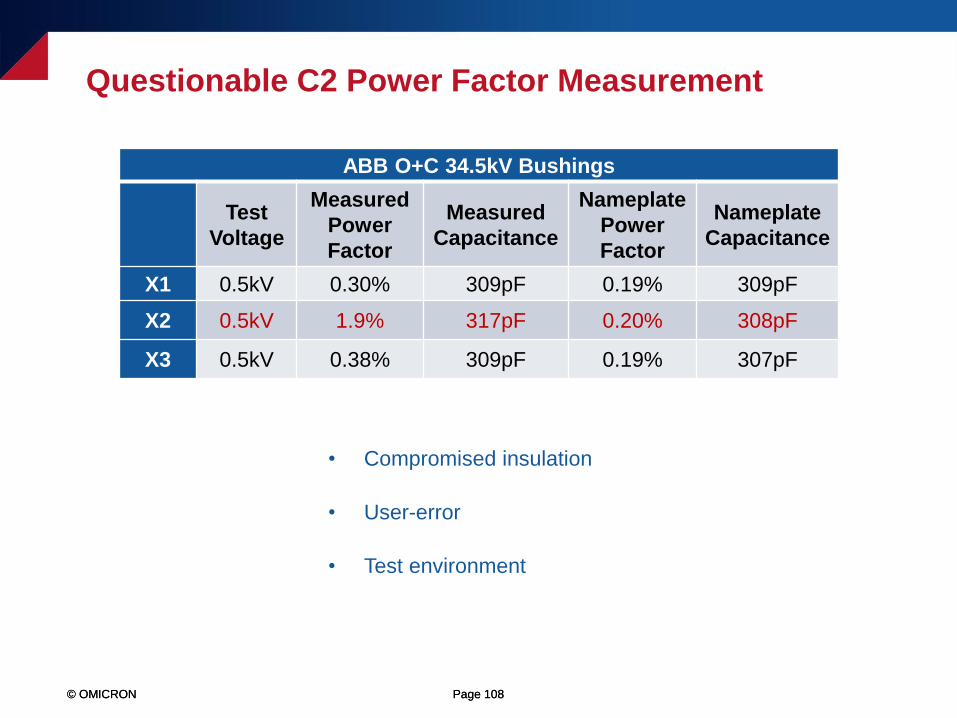
ABB O+C 34.5kV Bushings
Test
Voltage
Measured
Power
Factor
Measured
Capacitance
Nameplate
Power
Factor
Nameplate
Capacitance
X1 0.5kV 0.30% 309pF 0.19% 309pF
X2 0.5kV 1.9% 317pF 0.20% 308pF
X3 0.5kV 0.38% 309pF 0.19% 307pF
• Compromised insulation
• User-error
• Test environment
Questionable C2 Power Factor Measurement
© OMICRON Page 109© OMICRON Page 109
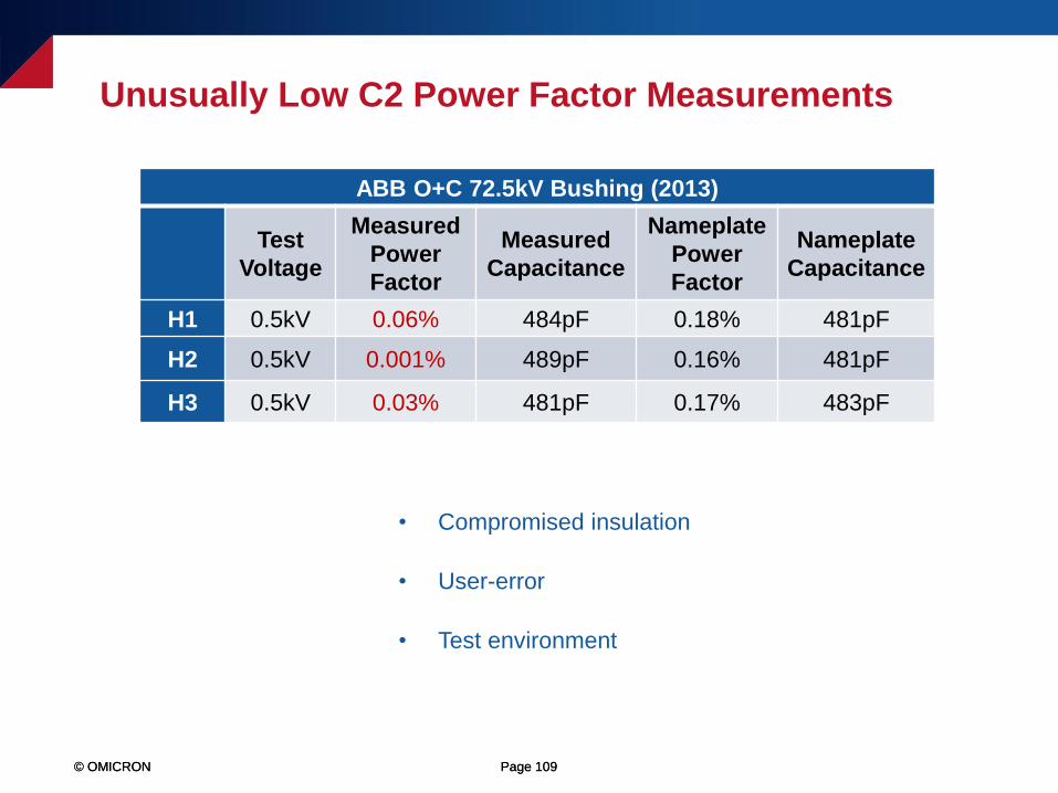
ABB O+C 72.5kV Bushing (2013)
Test
Voltage
Measured
Power
Factor
Measured
Capacitance
Nameplate
Power
Factor
Nameplate
Capacitance
H1 0.5kV 0.06% 484pF 0.18% 481pF
H2 0.5kV 0.001% 489pF 0.16% 481pF
H3 0.5kV 0.03% 481pF 0.17% 483pF
Unusually Low C2 Power Factor Measurements
• Compromised insulation
• User-error
• Test environment
© OMICRON Page 110© OMICRON Page 110
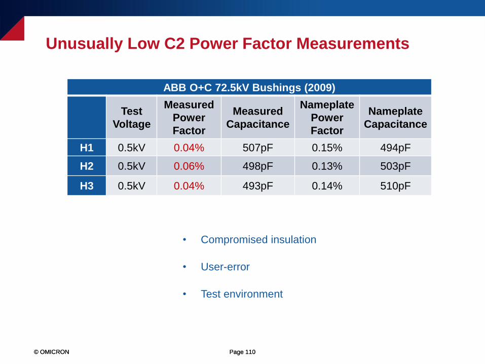
• Compromised insulation
• User-error
• Test environment
ABB O+C 72.5kV Bushings (2009)
Test
Voltage
Measured
Power
Factor
Measured
Capacitance
Nameplate
Power
Factor
Nameplate
Capacitance
H1 0.5kV 0.04% 507pF 0.15% 494pF
H2 0.5kV 0.06% 498pF 0.13% 503pF
H3 0.5kV 0.04% 493pF 0.14% 510pF
Unusually Low C2 Power Factor Measurements
© OMICRON Page 111© OMICRON Page 111
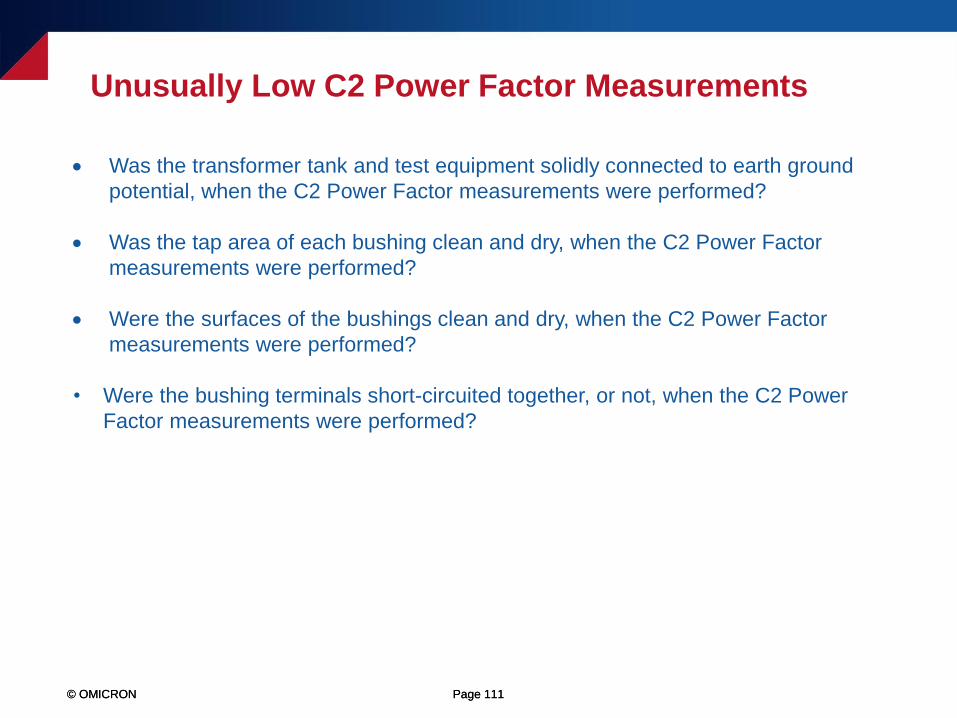
Unusually Low C2 Power Factor Measurements
• Was the transformer tank and test equipment solidly connected to earth ground
potential, when the C2 Power Factor measurements were performed?
• Was the tap area of each bushing clean and dry, when the C2 Power Factor
measurements were performed?
• Were the surfaces of the bushings clean and dry, when the C2 Power Factor
measurements were performed?
• Were the bushing terminals short-circuited together, or not, when the C2 Power
Factor measurements were performed?
© OMICRON Page 112© OMICRON Page 112
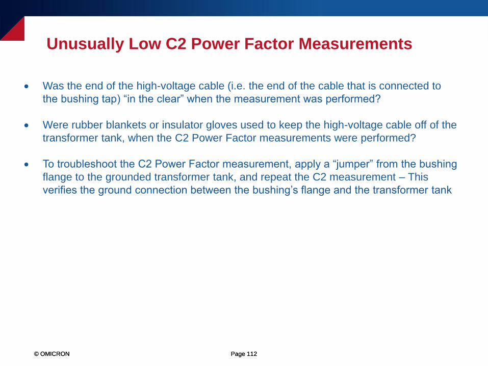
Unusually Low C2 Power Factor Measurements
• Was the end of the high-voltage cable (i.e. the end of the cable that is connected to
the bushing tap) “in the clear” when the measurement was performed?
• Were rubber blankets or insulator gloves used to keep the high-voltage cable off of the
transformer tank, when the C2 Power Factor measurements were performed?
• To troubleshoot the C2 Power Factor measurement, apply a “jumper” from the bushing
flange to the grounded transformer tank, and repeat the C2 measurement – This
verifies the ground connection between the bushing’s flange and the transformer tank

© OMICRON Page 113
Energized Collar (Hot Collar) Test Examples
© OMICRON Page 114© OMICRON Page 114
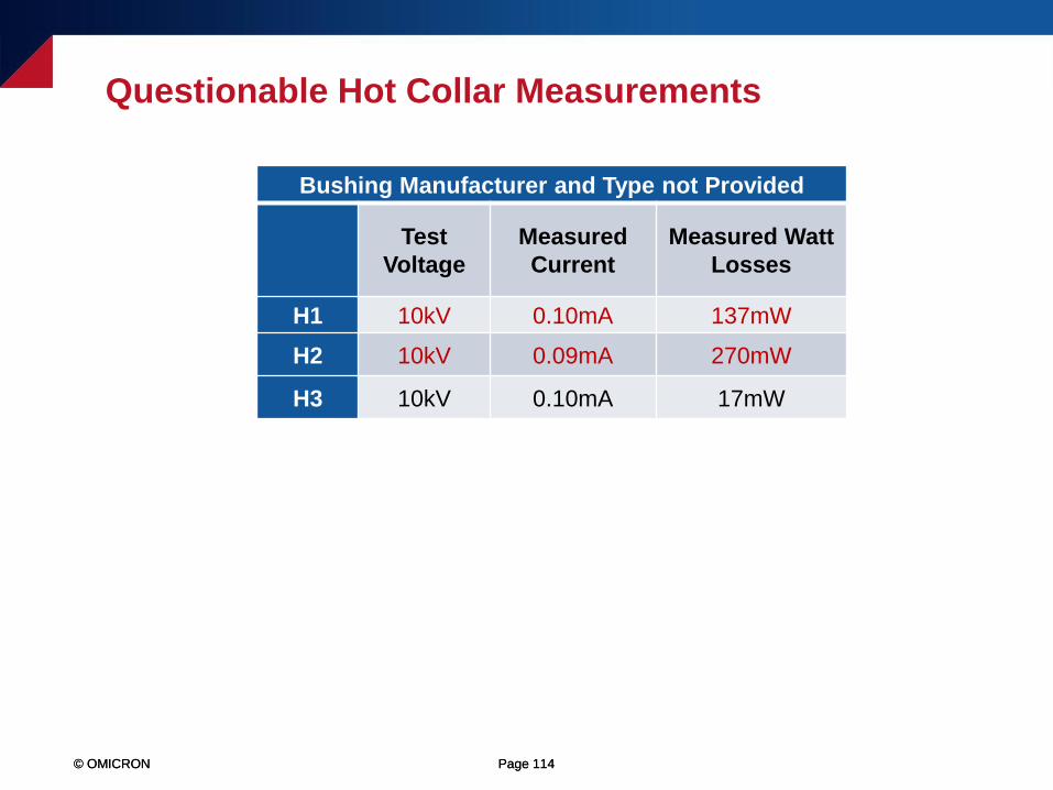
Questionable Hot Collar Measurements
Bushing Manufacturer and Type not Provided
Test
Voltage
Measured
Current
Measured Watt
Losses
H1 10kV 0.10mA 137mW
H2 10kV 0.09mA 270mW
H3 10kV 0.10mA 17mW
© OMICRON Page 115© OMICRON Page 115
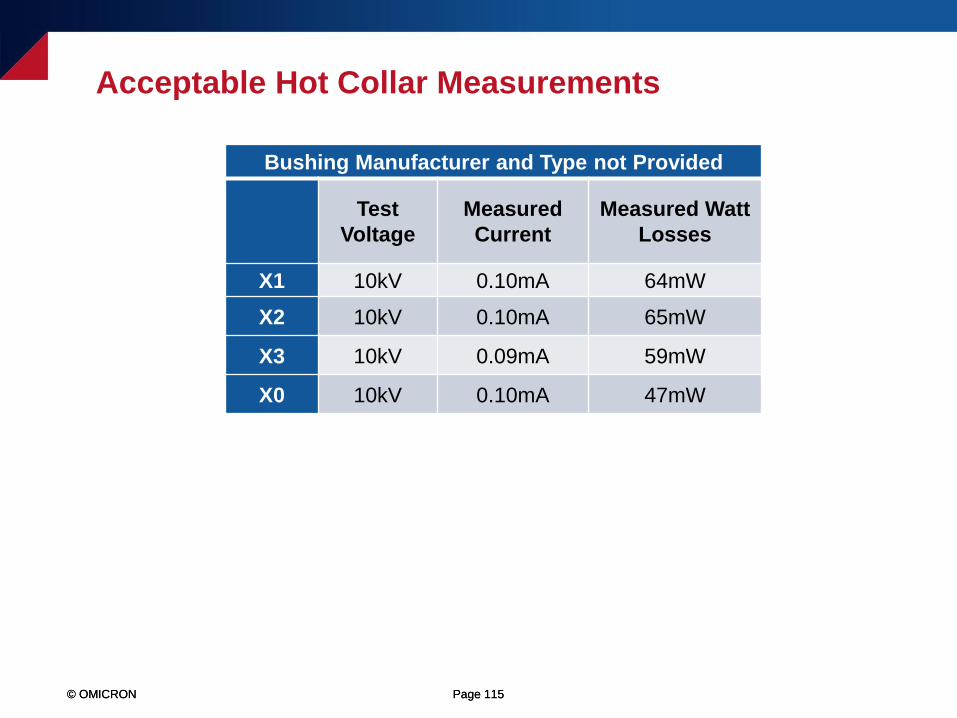
Acceptable Hot Collar Measurements
Bushing Manufacturer and Type not Provided
Test
Voltage
Measured
Current
Measured Watt
Losses
X1 10kV 0.10mA 64mW
X2 10kV 0.10mA 65mW
X3 10kV 0.09mA 59mW
X0 10kV 0.10mA 47mW
© OMICRON Page 116© OMICRON Page 116
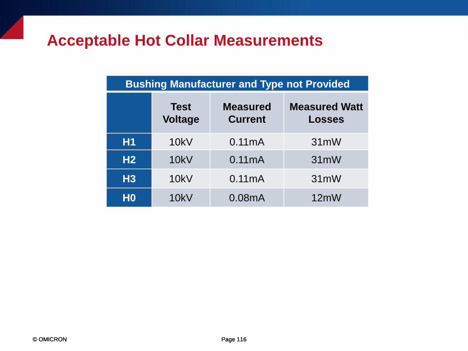
Acceptable Hot Collar Measurements
Bushing Manufacturer and Type not Provided
Test
Voltage
Measured
Current
Measured Watt
Losses
H1 10kV 0.11mA 31mW
H2 10kV 0.11mA 31mW
H3 10kV 0.11mA 31mW
H0 10kV 0.08mA 12mW
© OMICRON Page 117© OMICRON Page 117
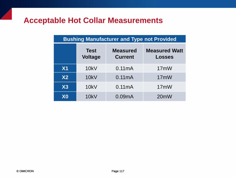
Acceptable Hot Collar Measurements
Bushing Manufacturer and Type not Provided
Test
Voltage
Measured
Current
Measured Watt
Losses
X1 10kV 0.11mA 17mW
X2 10kV 0.11mA 17mW
X3 10kV 0.11mA 17mW
X0 10kV 0.09mA 20mW

© OMICRON Page 118
A Bushing’s Influence on the Overall Power Factor Test
© OMICRON Page 119© OMICRON Page 119
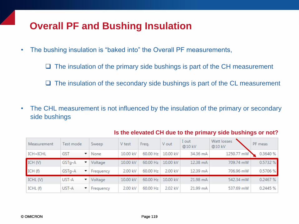
• The bushing insulation is “baked into” the Overall PF measurements,
The insulation of the primary side bushings is part of the CH measurement
The insulation of the secondary side bushings is part of the CL measurement
• The CHL measurement is not influenced by the insulation of the primary or secondary
side bushings
Overall PF and Bushing Insulation
Is the elevated CH due to the primary side bushings or not?
© OMICRON Page 120© OMICRON Page 120
• Negatively influence the Power Factor measurement – A bad bushing may cause an
Overall Power Factor measurement to increase
• Positively influence the Power Factor measurement - Healthy bushings may cause an
Overall Power Factor measurement to decrease (which may “mask” or hide a problem)
• Have no influence on the Overall Power Factor measurements
Bushing Insulation May...
© OMICRON Page 121© OMICRON Page 121
• If a transformer tests with an elevated CH or CL value, then we should first isolate and test
the insulation of the bushings, to determine if the abnormally high measurement is due to a
“bad” bushing or not
• Fortunately, if the C1 Power Factor measurement can be performed on the bushings, then
we can subtract the contribution of the bushings from the Overall Power Factor
measurement, to calculate the “true” CH and CL measurements
• To calculate the “true” CH measurement, the C1 Power Factor test must be performed on
the primary side bushings
• To calculate the “true” CL measurement, the C1 Power Factor test must be performed on
the secondary side bushings
Overall Power Factor and Bushing Insulation
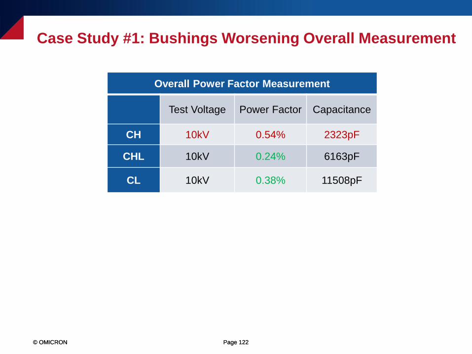
© OMICRON Page 122© OMICRON Page 122
Overall Power Factor Measurement
Test Voltage Power Factor Capacitance
CH 10kV 0.54% 2323pF
CHL 10kV 0.24% 6163pF
CL 10kV 0.38% 11508pF
Case Study #1: Bushings Worsening Overall Measurement
© OMICRON Page 123© OMICRON Page 123
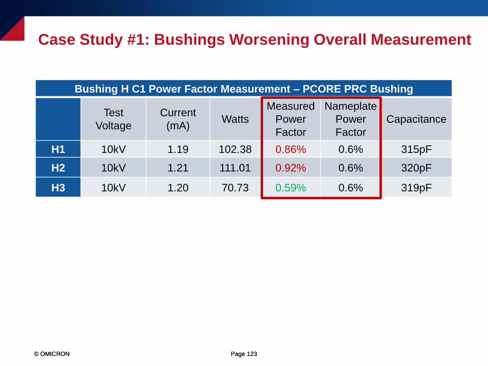
Bushing H C1 Power Factor Measurement – PCORE PRC Bushing
Test
Voltage
Current
(mA)Watts
Measured
Power
Factor
Nameplate
Power
Factor
Capacitance
H1 10kV 1.19 102.38 0.86% 0.6% 315pF
H2 10kV 1.21 111.01 0.92% 0.6% 320pF
H3 10kV 1.20 70.73 0.59% 0.6% 319pF
Case Study #1: Bushings Worsening Overall Measurement
© OMICRON Page 124© OMICRON Page 124
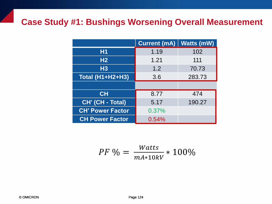
Current (mA) Watts (mW)
H1 1.19 102
H2 1.21 111
H3 1.2 70.73
Total (H1+H2+H3) 3.6 283.73
CH 8.77 474
CH' (CH - Total) 5.17 190.27
CH’ Power Factor 0.37%
CH Power Factor 0.54%
Case Study #1: Bushings Worsening Overall Measurement
© OMICRON Page 125© OMICRON Page 125
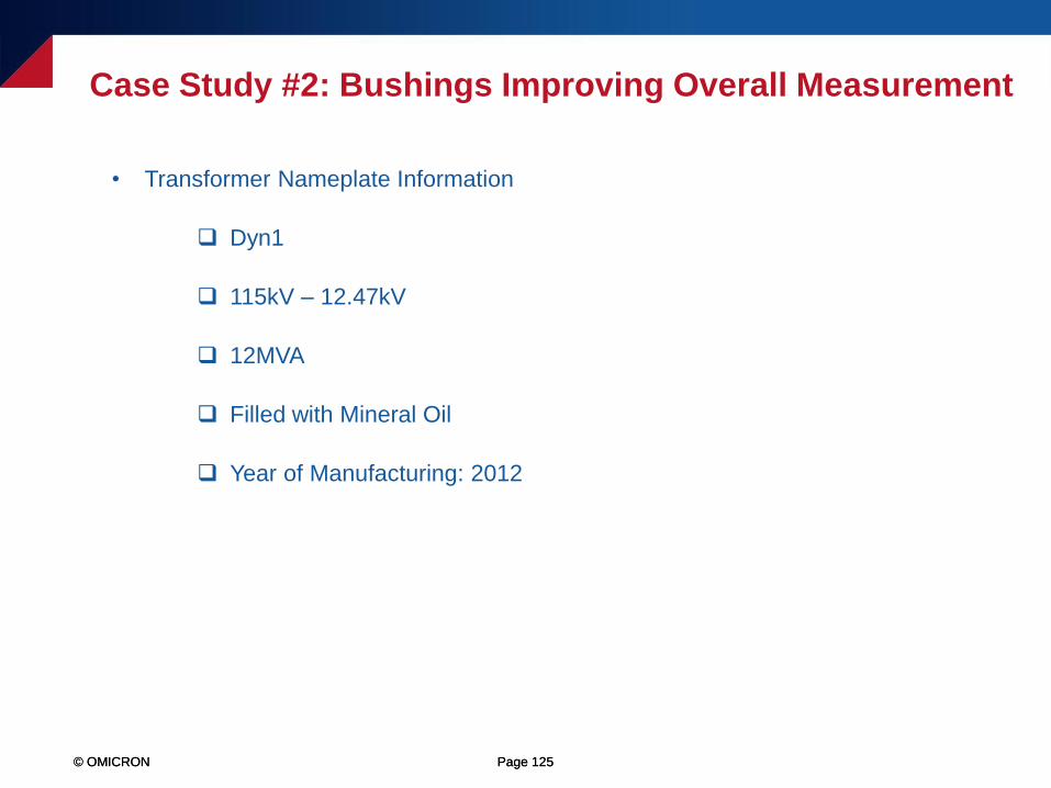
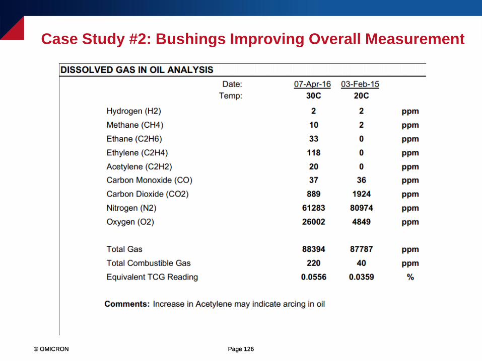
Case Study #2: Bushings Improving Overall Measurement
• Transformer Nameplate Information
Dyn1
115kV – 12.47kV
12MVA
Filled with Mineral Oil
Year of Manufacturing: 2012
© OMICRON Page 126© OMICRON Page 126
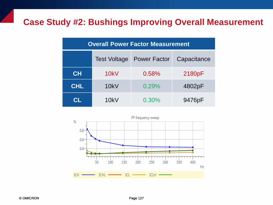
Case Study #2: Bushings Improving Overall Measurement
© OMICRON Page 127© OMICRON Page 127
Overall Power Factor Measurement
Test Voltage Power Factor Capacitance
CH 10kV 0.58% 2180pF
CHL 10kV 0.29% 4802pF
CL 10kV 0.30% 9476pF
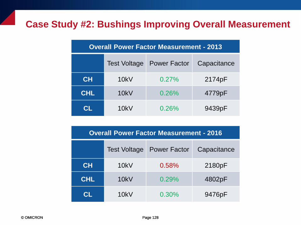
Case Study #2: Bushings Improving Overall Measurement
© OMICRON Page 128© OMICRON Page 128
Overall Power Factor Measurement - 2013
Test Voltage Power Factor Capacitance
CH 10kV 0.27% 2174pF
CHL 10kV 0.26% 4779pF
CL 10kV 0.26% 9439pF
Overall Power Factor Measurement - 2016
Test Voltage Power Factor Capacitance
CH 10kV 0.58% 2180pF
CHL 10kV 0.29% 4802pF
CL 10kV 0.30% 9476pF
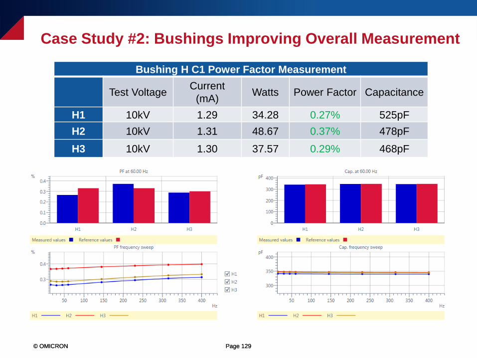
Case Study #2: Bushings Improving Overall Measurement
© OMICRON Page 129© OMICRON Page 129
Bushing H C1 Power Factor Measurement
Test VoltageCurrent
(mA)Watts Power Factor Capacitance
H1 10kV 1.29 34.28 0.27% 525pF
H2 10kV 1.31 48.67 0.37% 478pF
H3 10kV 1.30 37.57 0.29% 468pF
Case Study #2: Bushings Improving Overall Measurement
© OMICRON Page 130© OMICRON Page 130
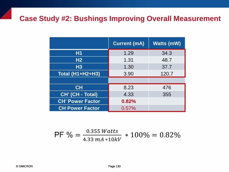
Current (mA) Watts (mW)
H1 1.29 34.3
H2 1.31 48.7
H3 1.30 37.7
Total (H1+H2+H3) 3.90 120.7
CH 8.23 476
CH' (CH - Total) 4.33 355
CH’ Power Factor 0.82%
CH Power Factor 0.57%
Case Study #2: Bushings Improving Overall Measurement
© OMICRON Page 131© OMICRON Page 131
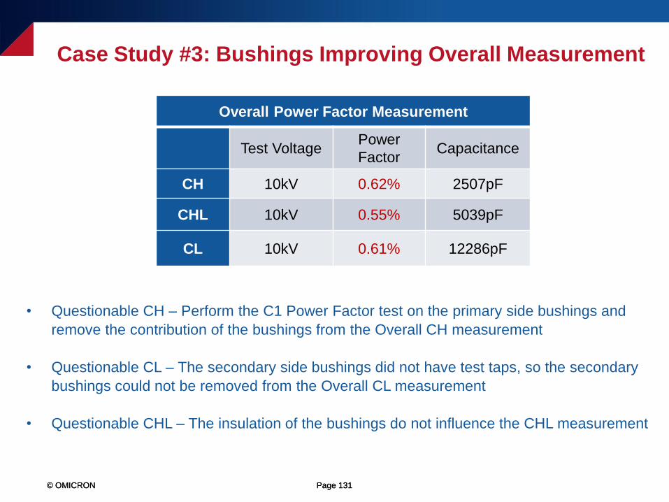
• Questionable CH – Perform the C1 Power Factor test on the primary side bushings and
remove the contribution of the bushings from the Overall CH measurement
• Questionable CL – The secondary side bushings did not have test taps, so the secondary
bushings could not be removed from the Overall CL measurement
• Questionable CHL – The insulation of the bushings do not influence the CHL measurement
Overall Power Factor Measurement
Test VoltagePower
FactorCapacitance
CH 10kV 0.62% 2507pF
CHL 10kV 0.55% 5039pF
CL 10kV 0.61% 12286pF
Case Study #3: Bushings Improving Overall Measurement
© OMICRON Page 132© OMICRON Page 132
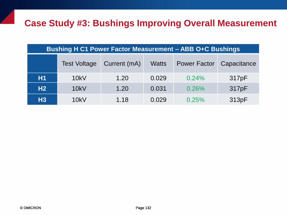
Bushing H C1 Power Factor Measurement – ABB O+C Bushings
Test Voltage Current (mA) Watts Power Factor Capacitance
H1 10kV 1.20 0.029 0.24% 317pF
H2 10kV 1.20 0.031 0.26% 317pF
H3 10kV 1.18 0.029 0.25% 313pF
Case Study #3: Bushings Improving Overall Measurement
© OMICRON Page 133© OMICRON Page 133
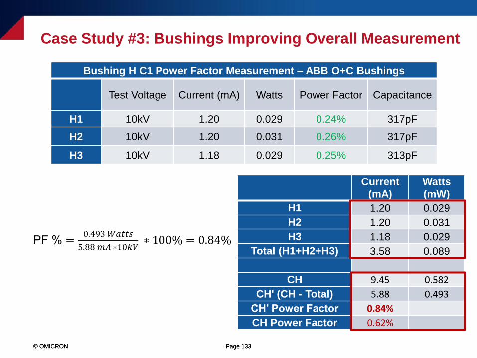
Current
(mA)
Watts
(mW)
H1 1.20 0.029
H2 1.20 0.031
H3 1.18 0.029
Total (H1+H2+H3) 3.58 0.089
CH 9.45 0.582
CH' (CH - Total) 5.88 0.493
CH’ Power Factor 0.84%
CH Power Factor 0.62%
Case Study #3: Bushings Improving Overall Measurement
Bushing H C1 Power Factor Measurement – ABB O+C Bushings
Test Voltage Current (mA) Watts Power Factor Capacitance
H1 10kV 1.20 0.029 0.24% 317pF
H2 10kV 1.20 0.031 0.26% 317pF
H3 10kV 1.18 0.029 0.25% 313pF
© OMICRON Page 134© OMICRON Page 134
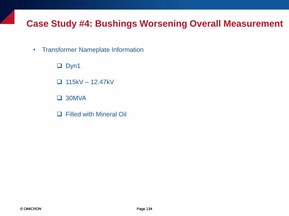
Case Study #4: Bushings Worsening Overall Measurement
• Transformer Nameplate Information
Dyn1
115kV – 12.47kV
30MVA
Filled with Mineral Oil
© OMICRON Page 135© OMICRON
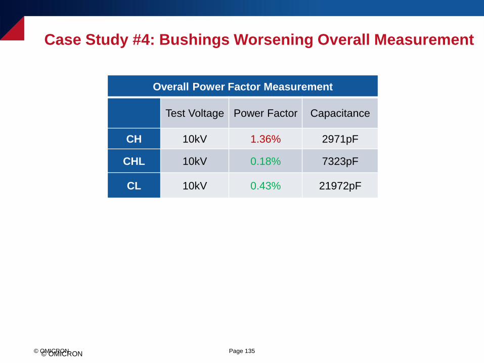
Overall Power Factor Measurement
Test Voltage Power Factor Capacitance
CH 10kV 1.36% 2971pF
CHL 10kV 0.18% 7323pF
CL 10kV 0.43% 21972pF
Case Study #4: Bushings Worsening Overall Measurement
© OMICRON Page 136© OMICRON
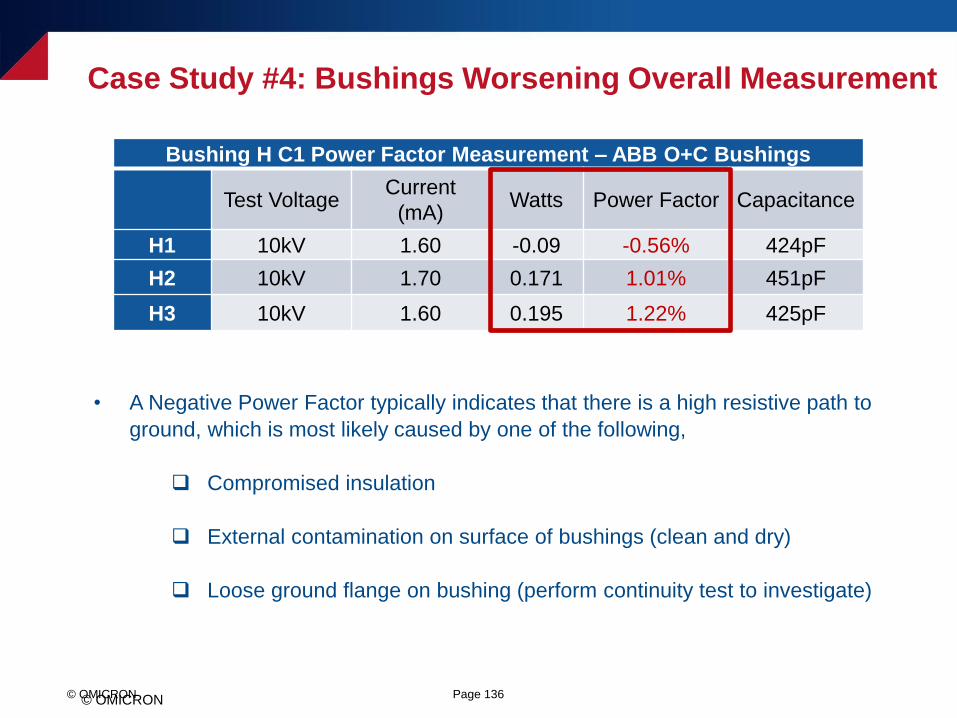
• A Negative Power Factor typically indicates that there is a high resistive path to
ground, which is most likely caused by one of the following,
Compromised insulation
External contamination on surface of bushings (clean and dry)
Loose ground flange on bushing (perform continuity test to investigate)
Bushing H C1 Power Factor Measurement – ABB O+C Bushings
Test VoltageCurrent
(mA)Watts Power Factor Capacitance
H1 10kV 1.60 -0.09 -0.56% 424pF
H2 10kV 1.70 0.171 1.01% 451pF
H3 10kV 1.60 0.195 1.22% 425pF
Case Study #4: Bushings Worsening Overall Measurement
© OMICRON Page 137© OMICRON
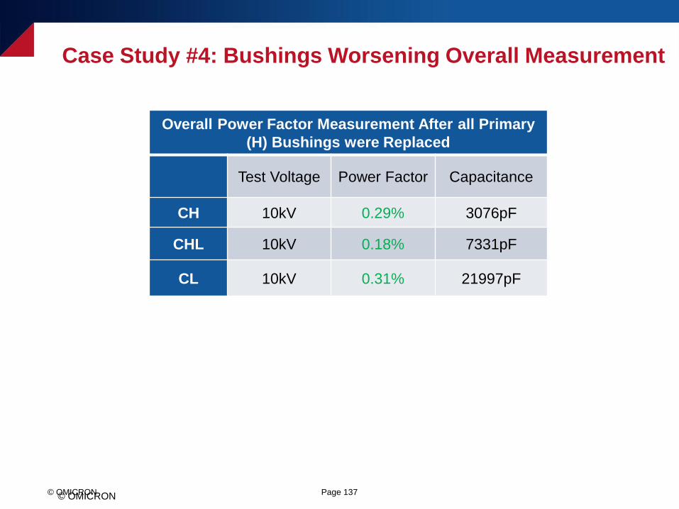
Overall Power Factor Measurement After all Primary
(H) Bushings were Replaced
Test Voltage Power Factor Capacitance
CH 10kV 0.29% 3076pF
CHL 10kV 0.18% 7331pF
CL 10kV 0.31% 21997pF
Case Study #4: Bushings Worsening Overall Measurement
© OMICRON Page 138© OMICRON Page 138
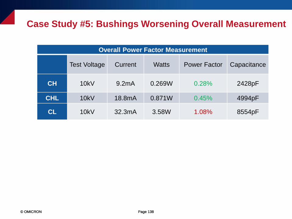
Overall Power Factor Measurement
Test Voltage Current Watts Power Factor Capacitance
CH 10kV 9.2mA 0.269W 0.28% 2428pF
CHL 10kV 18.8mA 0.871W 0.45% 4994pF
CL 10kV 32.3mA 3.58W 1.08% 8554pF
Case Study #5: Bushings Worsening Overall Measurement
© OMICRON Page 139© OMICRON Page 139
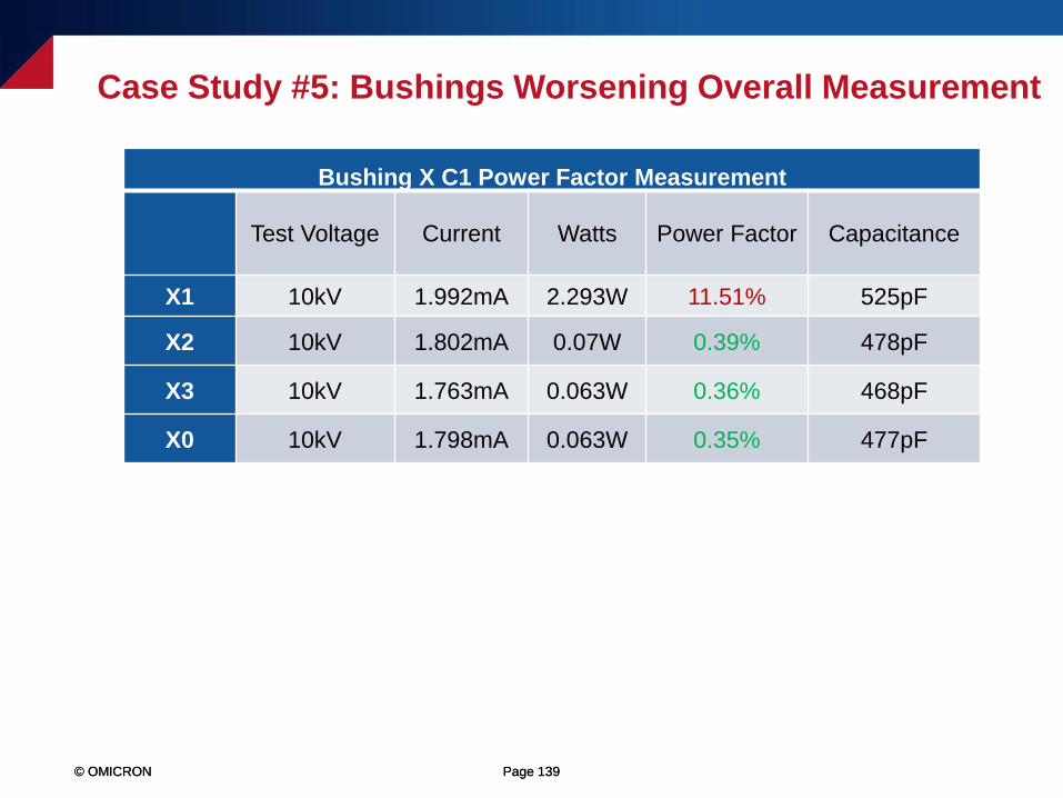
Bushing X C1 Power Factor Measurement
Test Voltage Current Watts Power Factor Capacitance
X1 10kV 1.992mA 2.293W 11.51% 525pF
X2 10kV 1.802mA 0.07W 0.39% 478pF
X3 10kV 1.763mA 0.063W 0.36% 468pF
X0 10kV 1.798mA 0.063W 0.35% 477pF
Case Study #5: Bushings Worsening Overall Measurement
© OMICRON Page 140© OMICRON Page 140
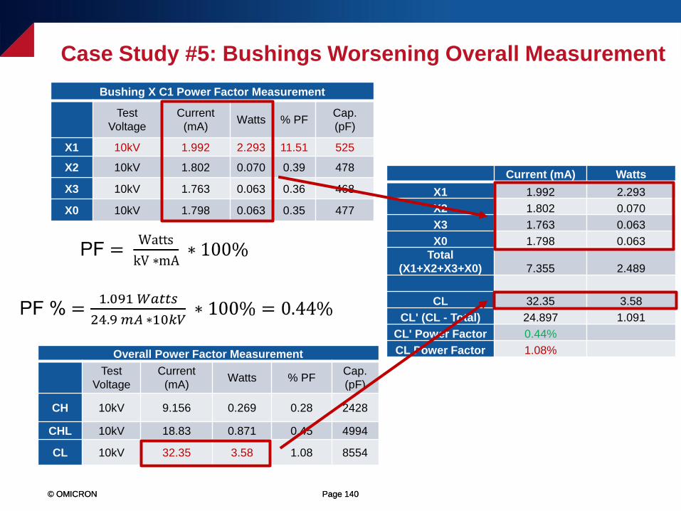
Current (mA) Watts
X1 1.992 2.293
X2 1.802 0.070
X3 1.763 0.063
X0 1.798 0.063
Total
(X1+X2+X3+X0) 7.355 2.489
CL 32.35 3.58
CL' (CL - Total) 24.897 1.091
CL' Power Factor 0.44%
CL Power Factor 1.08%
Bushing X C1 Power Factor Measurement
Test
Voltage
Current
(mA)Watts % PF
Cap.
(pF)
X1 10kV 1.992 2.293 11.51 525
X2 10kV 1.802 0.070 0.39 478
X3 10kV 1.763 0.063 0.36 468
X0 10kV 1.798 0.063 0.35 477
Overall Power Factor Measurement
Test
Voltage
Current
(mA)Watts % PF
Cap.
(pF)
CH 10kV 9.156 0.269 0.28 2428
CHL 10kV 18.83 0.871 0.45 4994
CL 10kV 32.35 3.58 1.08 8554
Case Study #5: Bushings Worsening Overall Measurement

© OMICRON Page 141
Troubleshooting a Questionable Bushing
Power Factor Test
© OMICRON Page 142© OMICRON Page 142
• Were the surfaces of the bushings cleaned and dried before the measurement
was performed?
Porcelain exterior – Use Windex or Collinite
Silicone exterior – Use a clean, dry rag
• If performing a C2 Power Factor measurement, clean and dry the tap area of
the bushing (use a clean, dry rag), and then repeat the test
• Were the bushings short-circuited together when the measurement was
performed? Did you use bare copper?
Troubleshooting a Bushing Power Factor Test
© OMICRON Page 143© OMICRON Page 143
Troubleshooting a Bushing Power Factor Test
• Is both the transformer and the test equipment solidly grounded to earth potential?
• Is there a solid connection from the bushing flange to the ground plane of the
transformer?
Perform a continuity test
Connect a jumper wire from the bushing flange to earth ground and retest the
bushing to determine if the results improve
• Connect the test equipment ground directly to the ground flange of the bushing,
and repeat the bushing Power Factor test
© OMICRON Page 144© OMICRON Page 144
• Were the bushings tested in the transformer tank or out of the transformer tank?
Is this a different test setup than the factory or previous measurement?
• Were the bushings tested in a wooden crate or on a wooden stand? Note,
bushings should only be tested in a metal stand or in a web sling
• Was the bushing suspended while it was tested? Was it suspended upright or at
an abnormal angle?
• Does the bushing require a bushing tap adapter? Was it properly applied?
Troubleshooting a Bushing Power Factor Test
© OMICRON Page 145© OMICRON
Abnormally Low or Negative Power Factor
• An “abnormally low” or negative Power Factor is typically caused by a high
resistive path to ground, which could be due to one of the following,
User error (e.g. a bad ground connection or a poor test connection)
Test environment – Moisture, high-humidity, rain, snow, cold temperatures, etc.
A test specimen that has a relatively low Capacitance value (typically defined
as less than 80pF)
A loose or poorly connected bushing ground flange (typically only relevant
when performing the C1 and C2 Power Factor measurements)
Compromised insulation
© OMICRON Page 146
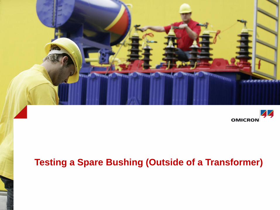
Testing a Spare Bushing (Outside of a Transformer)
© OMICRON Page 147© OMICRON Page 147
Testing a Spare Bushing (Outside of a Transformer)
• Do not test the bushing in a wooden crate or in a wooden stand
• Test the bushing in a metal stand, if possible
• A web sling may be used to suspend the bushing (upright)
The web sling must be clean and dry
Note, if suspended, ensure that the bushing does not tilt by more than
approximately 15° from the upright position
• Ground the bushing flange to earth potential
• Ground the test equipment directly to the bushing flange
© OMICRON Page 148© OMICRON Page 148
• Clean and dry the exterior surface of the bushing before testing
Porcelain exterior – Use Windex or Collinite
Silicone exterior – Use a clean, dry rag
• If the bushing does not have a tap, then perform the Overall test
• If the bushing has a tap, then perform the Overall, C1, and C2 tests
Testing a Spare Bushing (Outside of a Transformer)
© OMICRON Page 149
Thank you!