Busbar Systems 160800 A - · PDF fileVoltage Drop Calculation Voltage drop of a busbar system...
36
Busbar Systems 160...800 A
Transcript of Busbar Systems 160800 A - · PDF fileVoltage Drop Calculation Voltage drop of a busbar system...
Busbar Systems
160...800 A

w w w . e a e . c o m . t r
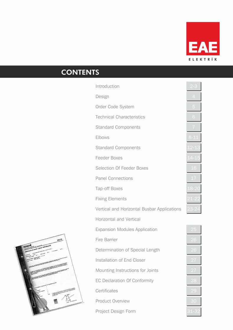
Introduction
Design
Order Code System
Technical Characteristics
Standard Components
Elbows
Standard Components
Feeder Boxes
Selection Of Feeder Boxes
Panel Connections
Tap-off Boxes
Fixing Elements
Vertical and Horizontal Busbar Applications
Fire Barrier
Determination of Special Length
Installation of End Closer
Mounting nstructions for Joints
E Declaration Of Conformity
Certificates
I
C
Product Overview
Project Design Form
Horizontal and Vertical
Expansion Modules Application
CONTENTS
2-3
4
5
6
7
8-
1 -1
1 -1
1
1
1 -
2
2
2
2
2
2
2
2
11
2 3
4 5
6
7
8 20
21-22
3-24
5
6
6
7
7
8
9
30
31-32
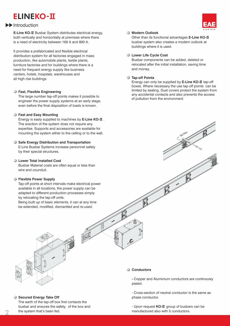
55 Nm
2
Introduction
E KO-LINE
E-Line KO- Busbar System distributes electrical energy,
both vertically and horizontally at premises where there
is a need of electricity between 160 A and 800 A.
It provides a prefabricated and flexible electrical
distribution system for all factories engaged in mass
production, like automobile plants, textile plants,
furniture factories and for buildings where there is a
need for frequent energy supply like business
centers, hotels, hospitals, warehouses and
all high rise buildings.
Modern Outlook
E-Line KO-Other than its functional advantages
busbar system also creates a modern outlook at
buildings where it is used.
Busbar components can be added, deleted or
relocated after the initial installation, saving time
and money.
Lower Life Cycle Cost
Tap-off Points
E-Line KO-Energy can only be supplied by tap-off
boxes. Where necessary the use tap-off points can be
limited by sealing. Dust covers protect the system from
any accidental contacts and also prevents the access
of pollution from the environment.
Fast, Flexible Engineering
Fast and Easy Mounting
E-Line KO-
Safe Energy Distribution and Transportation
Lower Total Installed Cost
Flexible Power Supply
The large number tap-off points makes it possible to
engineer the power supply systems at an early stage,
even before the final disposition of loads is known.
Energy is easly supplied to machines by .
The erection of the system does not require any
expertise. Supports and accessories are available for
mounting the system either to the celling or to the wall.
E-Line Busbar Systems increase personnel safety
by their special structures.
Busbar Material costs are often equal or less than
wire and counduit.
Tap-off points at short intervals make electrical power
available in all locations, the power supply can be
adapted to different production processes simply
by relocating the tap-off units.
Being built up of basic elements, it can at any time
be extended, modified, dismantled and re-used.
Conductors
-
KO-
Copper and Aluminium conductors are continously
plated.
- Cross-section of neutral conductor is the same as
phase conductor.
- Upon request group of busbars can be
manufactured also with 5 conductors.
Secured Energy Take Off
The earth of the tap-off box first contacts the
busbar and ensures the safety, of the box and
the system that’s been fed.
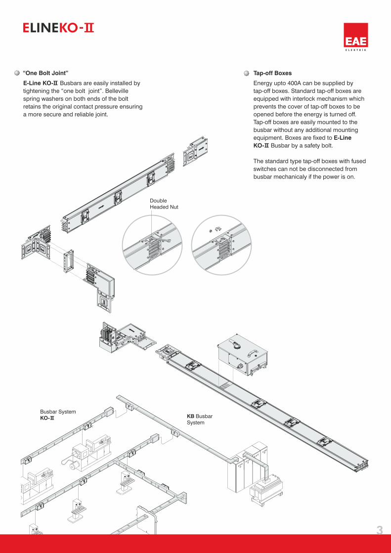
Busbar ystemS
KO- KB Busbar
System
“One Bolt Joint”
E-Line KO- Busbars are easily installed by
tightening the “one bolt joint”. Belleville
spring washers on both ends of the bolt
retains the original contact pressure ensuring
a more secure and reliable joint.
Tap-off Boxes
Energy upto 400A can be supplied by
tap-off boxes. Standard tap-off boxes are
equipped with interlock mechanism which
prevents the cover of tap-off boxes to be
opened before the energy is turned off.
Tap-off boxes are easily mounted to the
busbar without any additional mounting
equipment. Boxes are fixed to
Busbar by a safety bolt.
The standard type tap-off boxes with fused
switches can not be disconnected from
busbar mechanicaly if the power is on.
E-Line
KO-
3
E KO-LINE
Double
Headed Nut
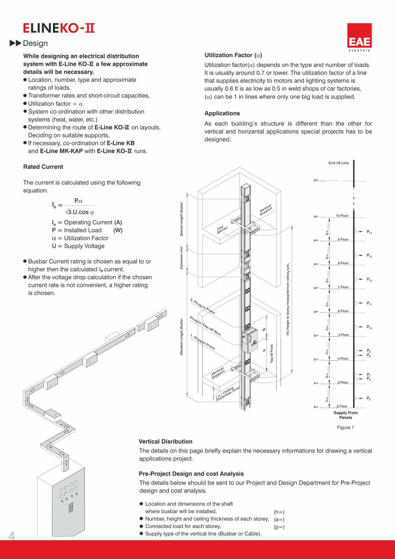
While designing an electrical distribution
system with E-Line KO- a few approximate
details will be necessary.
E-Line KO-
E-Line KB
E-Line MK-KAP E-Line KO-
Rated Current
Location, number, type and approximate
ratings of loads,
Transformer rates and short-circuit capacities,
Utilization factor =
System co-ordination with other distribution
systems (heat, water, etc.)
Determining the route of on layouts,
Deciding on suitable supports,
If necessary, co-ordination of
and with runs.
The current is calculated using the following
equation.
Busbar Current rating is chosen as equal to or
higher then the calculated I current.
After the voltage drop calculation if the chosen
current rate is not convenient, a higher rating
is chosen.
�
Applications
Utilization Factor ( )�
B
B
P.�
� �3.U.cosI =
BIP
U
= (A)= (W)==
Operating Current
Installed Load
Utilization Factor
Supply Voltage
Location and dimensions of the shaft
where busbar will be installed,
Number, height and ceiling thickness of each storey,
Connected load for each storey,
Supply type of the vertical line (Busbar or Cable).
(h=)
(a=)
(p=)
Utilization factor( ) depends on the type and number of loads.
It is usually around 0.7 or lower. The utilization factor of a line
that supplies electricity to motors and lighting systems is
usually 0.6 It is as low as 0.5 in weld shops of car factories,
( ) can be 1 in lines where only one big load is supplied.
�
�
As each building’s structure is different than the other for
vertical and horizantal applications special projects has to be
designed.
The details on this page briefly explain the necessary informations for drawing a vertical
applications project.
The details below should be sent to our Project and Design Department for Pre-Project
design and cost analysis.
Vertical Disribution
Pre-Project Design and cost Analysis
�
4
Design
E KO-LINE
Tap-
off P
oint
Fire
Barrier
Plug-İn Tap-off Box (H) H
eigh
t of s
tore
y m
easu
red
from
cei
ling
(cm
)
( a ) C
eiling
Thickness (cm)
1. Plug-in Point
3. Plug-in Point
Spec
ial L
engt
h B
usba
rSt
anda
rd L
engt
h B
usba
rEx
pans
ion
Uni
t
a= ......
a= ......
a= ......
a= ......
a= ......
a= ......
a= ......
a= ......
a= ......
a= ......
h=
.....
.h
= ..
....
h=
.....
.h
= ..
....
h=
.....
.h
= ..
....
h=
.....
.h
= ..
....
2.Floor
3.Floor
4.Floor
9.Floor
8.Floor
7.Floor
6.Floor
5.Floor
10.Floor
End Of Line
Figure 1
Supply From
Panels
P
P
P
P
P
PP
PP
P
14
13
12
11
10
9
8
7
6
5
AB
Vertical
Support
Vertical
Support
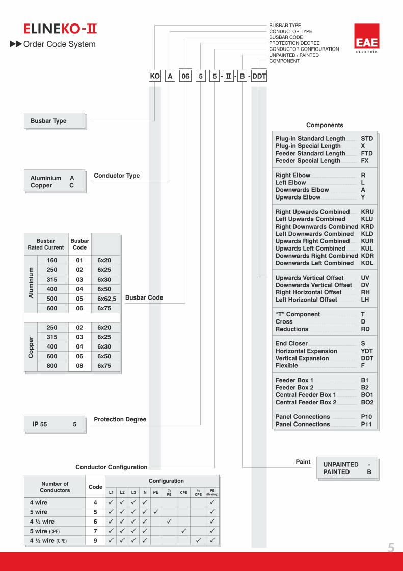
KO A 06 5 B5 - - - DDT
IP 55 5
Aluminium A
Copper C
UNPAINTED
PAINTED
-
B
Busbar Type
Conductor Type
Busbar Code
Protection Degree
Paint
BUSBAR TYPE
CONDUCTOR TYPE
BUSBAR CODE
PROTECTION DEGREE
CONDUCTOR CONFIGURATION
UNPAINTED / PAINTED
COMPONENT
160
250
315
400
500
600
250
315
400
600
800
01
02
03
04
05
06
02
03
04
06
08
6x20
6x25
6x30
6x50
6x62,5
6x75
6x20
6x25
6x30
6x50
6x75
Busbar
Rated Current
Alu
min
ium
Co
pp
er
Busbar
Code
CodeL1 L2 L3 N PE
½PE
CPE½
CPEPE
(Housing)
Number of
Conductors
4
5
6
7
9
Conductor Configuration
Configuration
4 wire
5 wire
4 ½ wire
5 wire
4 ½ wire
( )
( )
CPE
CPE
5
Order Code System
E KO-LINE
Plug-in Standard Length
Plug-in Special Length
Feeder Standard Length
Feeder Special Length
Right Elbow
Left Elbow
Downwards Elbow
Upwards Elbow
Right Upwards Combined
Left Upwards Combined
Right Downwards Combined
Left Downwards Combined
Upwards Right Combined
Upwards Left Combined
Downwards Right Combined
Downwards Left Combined
Upwards Vertical Offset
Downwards Vertical Offset
Right Horizontal Offset
Left Horizontal Offset
“T” Component
Cross
Reductions
End Closer
Horizontal Expansion
Vertical Expansion
Flexible
Feeder Box 1
Feeder Box 2
Central Feeder Box 1
Central Feeder Box 2
Panel Connections
Panel Connections
STD
X
FTD
FX
R
L
A
Y
KRU
KLU
KRD
KLD
KUR
KUL
KDR
KDL
UV
DV
RH
LH
T
D
RD
S
YDT
DDT
F
B1
B2
BO1
BO2
P10
P11
Components
L1, L2, L3, N
Power loss at rated current
mm²
mm²
kg/m
kg/m
mm²
mmxmm
mm²
V
V
Ue
Ui
m /m�
m /m�
kA
Icw
kA
Icw
kA
Ipk
kA
Ipk
W/m13I²R
kA
Ipk
AIn
kA
rmsIcw
20 m /m�
m /m�
m /m�
R
m /m�
f Hz
IP
01 02 03 04 05 06
120 150 180 300 375 450
120 150 180 300 375 450
7,0 7,5 8,0 10,0 11,0 12,0
7,3 8,0 8,7 11,0 12,0 13,0
583 593 603 643 668 693
60 75 90 150 187,5 225
1000
6x20 6x25 6x30 6x50 6x62,5 6x75
10,2 15,3 15,3 36 36 44,1
10,2 15,3 15,3 36 36 44,1
6 9 9 18 18 21
6 9 9 18 18 21
23,58 48,75 64,05 62,08 84,41 104,68
10 15 15 30 30 35
160 250 315 400 500 600
17 30 30 63,5 63,5 73,5
0,242
0,286
0,205
0,193
0,246
0,183
0,161
0,204
0,165
0,097
0,125
0,118
0,077
0,109
0,103
0,064
0,094
0,088
0,333
0,965
1,100
0,319
0,901
1,030
0,270
0,847
0,961
0,182
0,614
0,825
0,157
0,572
0,709
0,135
0,516
0,687
1000
50 / 60
55
0302 04 06 08
150120 180 300 450
11,010,0 12,5 16,0 18,0
12,511,0 14,0 19,0 21,0
593583 603 643 693
7560 90 150 225
6x256x20 6x30 6x50 6x75
0,2350,254
0,954
1,042
0,915
0,959
0,207
0,793
0,911
0,144
0,597
0,779
0,110
0,453
0,691
50,3335,36 70,92 86,19 133,56
150120 180 300 450
10,810,8 15 21 21
10,810,8 15 21 21
21,621,6 30 44,1 44,1
21,621,6 30 44,1 44,1
0,1540,173 0,144 0,117 0,083
3636 52,5 73,5 73,5
315250 400 600 800
1818 25 35 35
0,1200,150 0,100 0,060 0,040
0,1640,180 0,144 0,078 0,068
6
E KO-LINE
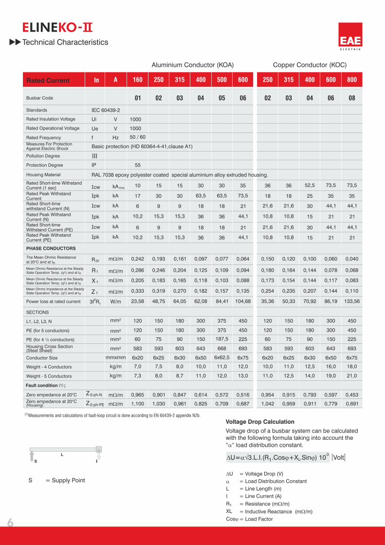
IEC 60439-2
Measures For ProtectionAgainst Electric Shock
PHASE CONDUCTORS
Zero empedance at 20°C
Zero empedance at 20°C(Housing)
(1)Fault condition ;
1R
1X
1Z
0-ph-N
0-ph-PE
Z
Z
L
S I
Measurements and calculations of fault-loop circuit is done according to EN 60439-2 appendix N2b.(1)
= Supply PointS
Basic protection (HD 60364-4-41,clause A1)
Aluminium Conductor (KOA) Copper Conductor (KOC)
Technical Characteristics
Rated Current
Standards
Busbar Code
Rated Operational Voltage
Rated Insulation Voltage
Rated Frequency
Protection Degree
Rated Short-time WithstandCurrent (1 sec)
Rated Short-timewithstand Current (N)
Rated Short-timeWithstand Current (PE)
Rated Peak WithstandCurrent (N)
Rated Peak WithstandCurrent (PE)
Rated Peak WithstandCurrent
The Mean Ohmic Resistance
at 20°C and at In
Mean Ohmic Resistance at the Steady
State Operation Temp. (q1) and at In
Mean Ohmic Reactance at the Steady
State Operation Temp. (q1) and at In
Mean Ohmic Impedance at the Steady
State Operation Temp. (q1) and at In
Pollution Degree
Housing Material RAL 7038 epoxy polyester coated special aluminium alloy extruded housing.
PE (for 5 conductors)
Weight - 4 Conductors
Weight - Conductors5
Housing Cross Section(Steel Sheet)
PE (for 4 ½ conductors)
Conductor Size
SECTIONS
Voltage Drop Calculation
Voltage drop of a busbar system can be calculated
with the following formula taking into account the
“ “ load distribution constant.�
� �� � �U 3.L.I.(R .Cos X .Sin ) 10= +1 L
-3
= Voltage Drop (V)
= Load Distribution Constant
= Line Length (m)
= Line Current (A)
= Resistance (m /m)
= Inductive Reactance (m /m)
= Load Factor
�
�
�
�
�
U
L
I
R
XL
Cos
1
Volt

Current Aluminium Copper
(A) (A)mm
(A)mm
Please call us for non-standard components.
Busbar cross-section dime sionsn
Electrical Energy up to 400A can be supplied
from the busbar by Tap-off boxes.
Busbar is manufactured in 3m as
standard, special lengths can be manufactured
on request.
E-Line KO-
A
180
L1
L2
L3
NPE
-707580-
100125
707580
100112125
-
160250315400500600800
625 500
500375 500 500
3000
500 625
500 500 500 375
3000
X
X
Plug-in
Standard Length
7
Standard Components
3000
Feeder
Standard Length
E KO-LINE
Minimum special length that can
be manufactured is 35 cm.
L1
L2
L3
NPE
X Special
Straight Length
(cm)
L1
L2
L3
NPE
X Special
Straight Length
(cm)
L1
L2
L3
NPE
Plug-in
Special Straight Length
Feeder
Special Straight Length
Sample Order:
250 A, Aluminium, Plug-in,
IP 55, 4 Conductors
KOA 0254- -STD STD
FTD
Sample Order:
400 A, Copper, Plug-in,
IP 55, 85 cm. 5 Conductors
KOC 0455- -85
Sample Order:
315 A, Aluminium, Feeder,
IP 55, 5 Conductors
KOA 0355- - TDF
Sample Order:
160 A, Aluminium, Feeder,
IP 55, 60 cm, 4 Conductors
KOA 0154- -60
-
-
L1
L2
L3
NPE
X
FX
KO - - -
BUSBAR TYPE
CONDUCTOR TYPE
BUSBAR CODE
PROTECTION DEGREE
CONDUCTOR CONFIGURATION
UNPAINTED / PAINTED
COMPONENT

B
A
B
A
C
D
C
D
AB
AB
C D
D
C
KOA 0254 - - R
KOC 0655 - - L
KOA 0454 - - A
KOC 0655 - - Y
R
L
A
Y
L1
L1
L1
L1
L2
L2
L2
L2
L3
L3
L3
L3
N
N
N
N
PE
PE
PE
PE
8
E KO-LINE
160250315400500600
800
250315400600
180185190210222235
180185190210235
145147150160166172
145147150160172
200200200200200200
200200200200200
290290290290290290
290290290290290
A B C D
Please call us for non-standard components.
Sample Order:
250 A, Aluminium, IP 55, 4 Conductors
Sample Order:
600 A, Copper, IP 55, 5 Conductors
Sample Order:
400 A, Aluminium, IP 55, 4 Conductors
Sample Order:
600 A, Copper, IP 55, 5 Conductors
Left Elbow
Downwards Elbow
Upwards ElbowCurrent
Alu
min
ium
Co
pp
er
Elbows
KO - - -
BUSBAR TYPE
CONDUCTOR TYPE
BUSBAR CODE
PROTECTION DEGREE
CONDUCTOR CONFIGURATION
UNPAINTED / PAINTED
COMPONENT
Right Elbow
CD
Y
Y
BA
CD
BA
X
A
B
AB
X
L1
L2
L3
NPE
L1
L2
L3
NPE
L1
L2
L3
NPE
L1
L2
L3
NPE
UV
DV
RH
LH
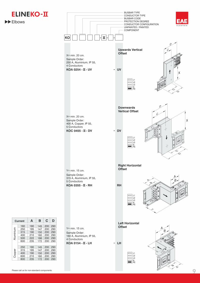
KOA 0254 - - UV
KOC 0455 - - DV
KOA 0355 - - RH
KOA 0154 - - LH
9
E KO-LINE
160250315400500600
800
250315400600
180185190210222235
180185190210235
145147150160166172
145147150160172
200200200200200200
200200200200200
290290290290290290
290290290290290
A B C D
Right Horizontal
Offset
Left Horizontal
Offset
Upwards Vertical
Offset
Downwards
Vertical Offset
Sample Order:
315 A, Aluminium, IP 55,
5 Conductors
Sample Order:
160 A, Aluminium, IP 55,
4 Conductors
Current
Alu
min
ium
Co
pp
er
Please call us for non-standard components.
Sample Order:
250 A, Aluminium, IP 55,
4 Conductors
X= min. 20 cm.
Sample Order:
400 A, Copper, IP 55,
5 Conductors
Y= min. 15 cm.
X= min. 20 cm.
Y= min. 15 cm.
Elbows
KO - - -
BUSBAR TYPE
CONDUCTOR TYPE
BUSBAR CODE
PROTECTION DEGREE
CONDUCTOR CONFIGURATION
UNPAINTED / PAINTED
COMPONENT

L1
L2
L3
NPE
L1
L2
L3
NPE
L1
L2
L3
NPE
L1
L2
L3
NPE
Y
BA
X
X
Y
BA
B A
B
A
KRU
KLU
KRD
KLD
KOA 0254 - - KRU
KOC 0455 - - KLU
KOA 0355 - - KRD
KOA 0154 - - KLD
10
E KO-LINE
160250315400500600
800
250315400600
180185190210222235
180185190210235
145147150160166172
145147150160172
200200200200200200
200200200200200
290290290290290290
290290290290290
A B C D
Right Downwards
Combined Offset
Left Downwards
Combined Offset
Right Upwards
Combined Offset
Left Upwards
Combined Offset
Sample Order:
250 A, Aluminium, IP 55,
4 Conductors
Sample Order:
400 A, Copper, IP 55,
5 Conductors
Sample Order:
315 A, Aluminium, IP 55,
5 Conductors
Sample Order:
160 A, Aluminium, IP 55,
4 Conductors
Please call us for non-standard components.
Elbows
Y= min. 20 cm.
Y= min. 20 cm.
X= min. 20 cm.
X= min. 20 cm.
KO - - -
BUSBAR TYPE
CONDUCTOR TYPE
BUSBAR CODE
PROTECTION DEGREE
CONDUCTOR CONFIGURATION
UNPAINTED / PAINTED
COMPONENT
Current
Alu
min
ium
Co
pp
er

B
B
A
A
Y
Y
C
B
A
D
A
B
C
C
X
X
D
D
DC
L1
L2
L3
NPE
L1
L2
L3
NPE
L1
L2
L3
NPE
L1
L2
L3
NPE
KUR
KUL
KDR
KDL
KOA 0254 - - KUR
KOC 0455 - - KUL
KOA 0355 - - KDR
KOA 0154 - - KDL
11
E KO-LINE
160250315400500600
800
250315400600
180185190210222235
180185190210235
145147150160166172
145147150160172
200200200200200200
200200200200200
290290290290290290
290290290290290
A B C D
Downwards Right
Combined Offset
Downwards Left
Combined Offset
Upwards Right
Combined Offset
Upwards Left
Combined Offset
Sample Order:
250 A, Aluminium, IP 55,
4 Conductors
Sample Order:
400 A, Copper, IP 55,
5 Conductors
Sample Order:
315 A, Aluminium, IP 55,
5 Conductors
Sample Order:
160 A, Aluminium, IP 55,
4 Conductors
Please call us for non-standard components.
Elbows
Y= min. 20 cm.
Y= min. 20 cm.
X= min. 20 cm.
X= min. 20 cm.
Current
Alu
min
ium
Co
pp
er
KO - - -
BUSBAR TYPE
CONDUCTOR TYPE
BUSBAR CODE
PROTECTION DEGREE
CONDUCTOR CONFIGURATION
UNPAINTED / PAINTED
COMPONENT

Standart dışı modüller için lütfen firmamızı arayınız.
D
T
AB
AA
L1
L2
L3
NPE
12
E KO-LINE
640
L1
L2
L3
N
L1
L2
L3
NPE
PE
Please call us for non-standard components.
Sample Order:
250 A, Aluminium, IP 55,
4 Conductors
Sample Order:
600 A, Aluminium, IP 55,
4 Conductors
Sample Order:
400-250 A, Aluminium,
IP 55,5 Conductors
KOA 0254 - - T
KOA 0654 - - D
KOA 0455 - - RD2
“T” Component
Cross
Reduction
RD
Reduced
Current
160 A 1
250 A 2
315 A 3
400 A 4
500 A 5
600 A 6
Reduction
Is used to change the busbar
cross section.
BACurrent
160250315400500600
800
250315400600
290295300320332345
290295300320345
145147150160166172
145147150160172
Alu
min
ium
Co
pp
er
Standard Components
KO - - -
BUSBAR TYPE
CONDUCTOR TYPE
BUSBAR CODE
PROTECTION DEGREE
CONDUCTOR CONFIGURATION
UNPAINTED / PAINTED
COMPONENT

KOC 0255 - - S S
100
13
E KO-LINE
KOA 0254 - - YDT YDT
1000
L1
L2
L3
NPE
KOC 0255 - - DDT DDT700
L1
L2
L3
NPE
KOA 0454 - - F55 F*
Y
L
ZX
L(Cm)
Standard Components
KO - - -
BUSBAR TYPE
CONDUCTOR TYPE
BUSBAR CODE
PROTECTION DEGREE
CONDUCTOR CONFIGURATION
UNPAINTED / PAINTED
COMPONENT
Please call us for non-standard components.
* Please indicate X, Y, Z and ø measurement on order.
End Closer
Horizontal Expansion
Flexibles
Vertical Expansion
Sample Order:
250 A, Copper, IP 55, 5 Conductors
Sample Order:
250 A, Aluminium, IP 55, 4 Conductors
Sample Order:
400 A, Aluminium, 4 Conductors 55 cm.
Sample Order:
250 A, Copper, IP 55, 5 Conductors
End Closer
Is used to close the end of busbar run.
Horizontal Expansion
For long horizontal runs and for
crossing the building expansions.
(See page no.25 for application)
Vertical Expansion
For vertical applications in
many storey buildings.
(See page no.25 for application)
Flexibles
Are used for panel-busbar
connections.
B2
B1
L1
L2
L3
NPE
Y Y
X
X
X
X
D
A
B
B
C
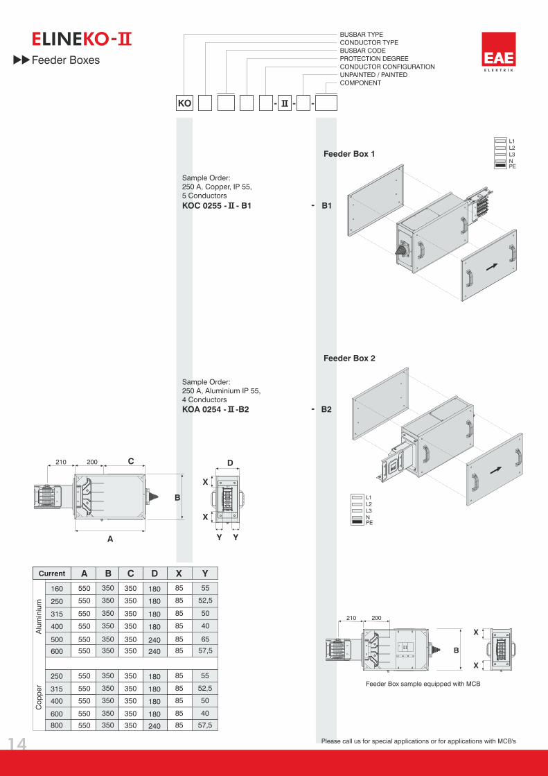
A C D X YB
160 550 350 350 180 85 55
550
550
350
350
350
350
180
180
85
52,5
52,5
85
550 350 350 180 85 50
550 350 350 180 85 40
550 350 350 240 85 65
550 350 350 240 85 57,5
550 350 350 180 5585
550 350 350 180 5085
550 350 350 180 4085
550 350 350 240 57,585
250
315
400
500
600
250
315
400
600
800
210
210
200
200
KOC 0255 - - B1
KOA 0254 - -B2
L1
L2
L3
NPE
14
E KO-LINE
Feeder Box sample equipped with MCB
Please call us for special applications or for applications with MCB's
Feeder Box 1
Feeder Box 2
Current
Alu
min
ium
Co
pp
er
Sample Order:
250 A, Copper, IP 55,
5 Conductors
Sample Order:
250 A, Aluminium IP 55,
4 Conductors
Feeder Boxes
KO - - -
BUSBAR TYPE
CONDUCTOR TYPE
BUSBAR CODE
PROTECTION DEGREE
CONDUCTOR CONFIGURATION
UNPAINTED / PAINTED
COMPONENT

KOA 0654 - - BO1
Central
Feeder Box BO 1
KOA 0654 - - BO2
Central
Feeder Box BO 2
BO2
BO1
600
210
210
365
365
60
0
L1
L1
L2
L2
L3
L3
N
N
PE
PE
230
600
210
210
60
0
230
15
E KO-LINE
36
5
14
5
27
0
107,5
N L3 L2 L1
PE
KO - - -
BUSBAR TYPE
CONDUCTOR TYPE
BUSBAR CODE
PROTECTION DEGREE
CONDUCTOR CONFIGURATION
UNPAINTED / PAINTED
COMPONENT
Feeder Boxes
(Central O)Feeder Box B
Please call us for special applications or for applications with MCB's
Sample Order:
600 A, Aluminium, IP 55,
4 Conductors
Sample Order:
600 A, Aluminium IP 55,
4 Conductors
16
L1
L2
L3
N PE
B1
B1
B2
B2
B2
B1
E KO-LINE
L1
L2
L3
NPE
15
0 m
m.
15
0 m
m. 150 mm.
Tavan
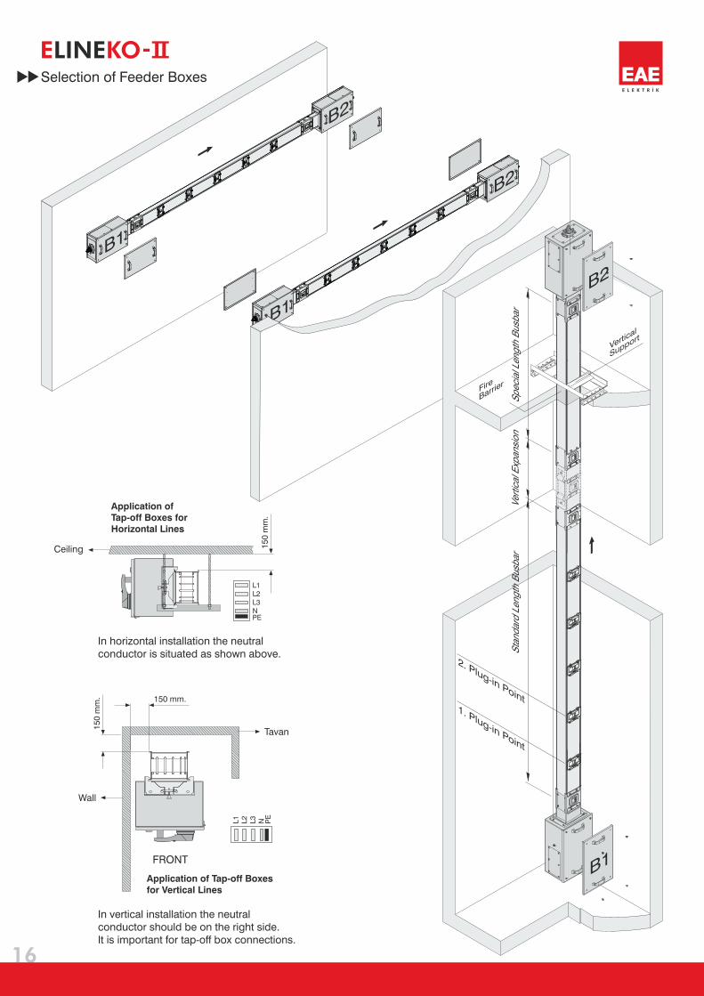
In vertical installation the neutral
conductor should be on the right side.
It is important for tap-off box connections.
Selection of Feeder Boxes
Application of
Tap-off Boxes for
Horizontal Lines
Application of Tap-off Boxes
for Vertical Lines
FRONT
In horizontal installation the neutral
conductor is situated as shown above.
Ceiling
Wall
2. Plug-in Point1. Plug-in Point
Sp
ecia
l Len
gth
Bu
sbar
Ver
tical
Exp
ansi
on
Sta
nd
ard
Len
gth
Bu
sbar
Fire
Barrier
Vertical
Support
L1L2
L3
NPE
20
0
41
0
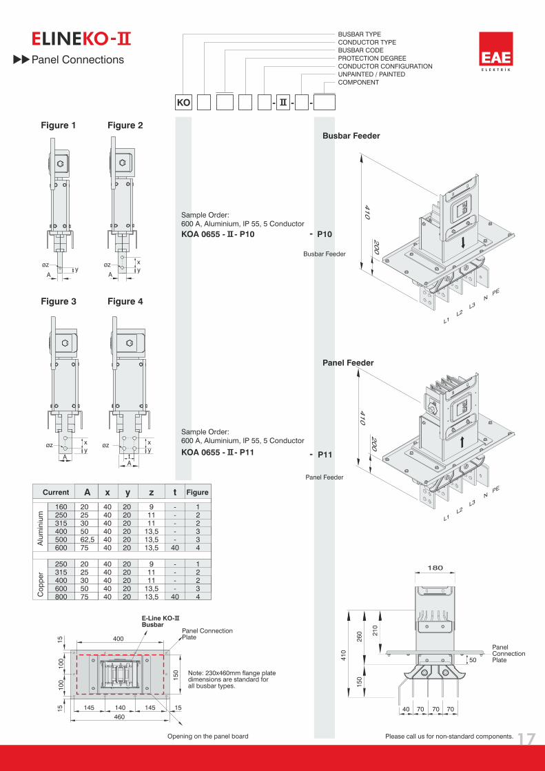
KOA 0655 - - P11
KOA 0655 - - P10
A A
AA
y y
y y
x
x x
øz
øz øz
øz
t
A
160250315400500600
00
2503154006008
2025305062,575
2025305075
404040404040
4040404040
202020202020
2020202020
91111
13,513,513,5
91111
13,513,5
-----
40
----
40
122334
12234
x y z t
17
E KO-LINE
70707040
180
26
0 21
0
50
15
0
41
0
15
15
10
01
00 1
50
400
145
460
145 15140
P11
P10
L1L2
L3
NPE
20
0
41
0
Panel Connections
BUSBAR TYPE
CONDUCTOR TYPE
BUSBAR CODE
PROTECTION DEGREE
CONDUCTOR CONFIGURATION
UNPAINTED / PAINTED
COMPONENT
KO - - -
Figure 1 Figure 2
Figure 3 Figure 4
Busbar Feeder
Panel Feeder
Sample Order:
600 A, Aluminium, IP 55, 5 Conductor
Sample Order:
600 A, Aluminium, IP 55, 5 Conductor
Panel Feeder
Busbar Feeder
Alu
min
ium
Co
pp
er
Current Figure
Panel ConnectionPlate
E-Line KO-Busbar
Note: 230x460mm flange platedimensions are standard forall busbar types.
Opening on the panel board
PanelConnectionPlate
Please call us for non-standard components.

Standart dışı Çıkış Kutuları için lütfen firmamızı arayınız.
KOP 1651-S
KOP 2551-S
KOP 4051-S
A
B
B
B
A
A
18
E KO-LINE
L1L2L3N
L1L2L3N
L1L2L3N
A30 30
50
KOP 160
250
400
KOP
KOP
AmmA
Bmm
Cmm
RP2
RP3
RPK1370
0
625
48
3 0
380
380
0 195
245
255
49795
49797
95053
NH 00
NH 1
NH2
KYA
KYA
SYK
KO
BUSBAR TYPE
BOX TYPE
BOX RATINGPROTECTION
DEGREE
FUSED
SWITCHES TYPE
IP 55 5
S- STANDARD SYK
B- EMPTY
15P
160 A - 16
250 A - 25
400 A - 40
Cable Gland Plates
Tap-Off Boxes
with Fused Switches (SYK)
Mat.Cable
Gland Type
Order
Code
Inner
Diameter
(mm)Sheet
Metal
RP0----
Sheet
MetalRP1 25M32
M40Sheet
Metal
RP2 32
Sheet
Metal
RP3 63Special
AL RP4 632xSpecial
RP5 18
RP6 25
RP7 32
RP8 25
AL 4xM25
AL 4xM32
AL 4xM40
AL 8xM32
Fused Switches (SYK)
Tap-off boxes are equipped with
EAE syk fused switches that;
Can operate under load,
Are equipped with NH fuse holders,
Have Interlock mechanism
Padlock applicable
Tap-off boxes can be equipped with
other brand of fused switches on request.
Tap-off boxes are painted in red
as standard.
Continuous current of tap-off boxes
with fused switch should not exceed 80% of
tap-off box current rating.
GlandPlates
(at tw
osides)
GlandPlates
(at th
ree
sides)
GlandPlates
(at th
ree
sides)
CURRENT Cable
Gland
5W
Order No.
Fused
SwitchesFuse
Size
KOP 160
250
400
KOP
KOP
AmmA
Bmm
Cmm
RPK3
RP3
RPK220
5 0
6 5
4
0
7
3 0
3 0
3 0
0
0
0
2
2
2
20
20
20
35484
35486
35504
KO
BUSBAR TYPE
BOX TYPE
BOX RATINGPROTECTION
DEGREE
FUSED
SWITCHES TYPE
IP 55 5
15P
160 A - 16
250 A - 25
400 A - 40
KOP 1651-M1
KOP 1651-B1
KOP 4051-M1
KOP 4051-B1
KOP 2551-M1
KOP 2551-B1
19
E KO-LINE
B
A30 30
L1L2L3N
L1L2L3N
L1L2L3N
50
A
A
A
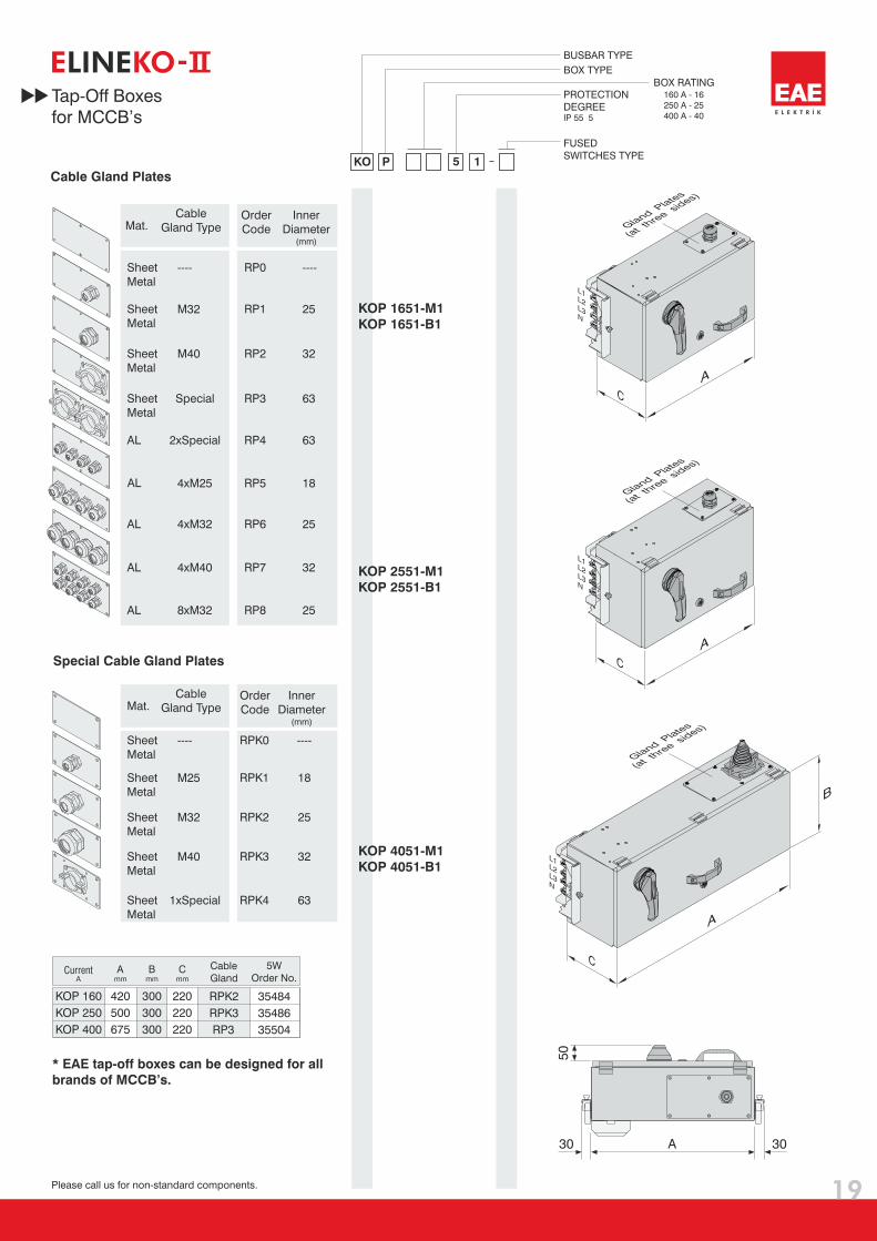
Cable Gland Plates
Special Cable Gland Plates
GlandPlates
(at th
ree
sides)
GlandPlates
(at th
ree
sides)
GlandPlates
(at th
ree
sides)
Mat.Cable
Gland TypeOrder
Code
Inner
Diameter(mm)
Sheet
Metal
RP0---- ----
Sheet
Metal
RP1 25M32
M40Sheet
Metal
RP2 32
Sheet
Metal
RP3 63Special
AL RP4 632xSpecial
AL RP5 184xM25
AL RP6 254xM32
AL RP7 324xM40
AL RP8 258xM32
Mat.Cable
Gland Type
Sheet
Metal
----
Sheet
MetalM25
M32
M40
1xSpecial
Sheet
Metal
Sheet
Metal
Sheet
Metal
Order
Code
Inner
Diameter(mm)
RPK0 ----
RPK1 18
RPK2
RPK3
RPK4
25
32
63
Tap-Off Boxes
for MCCB’s
Please call us for non-standard components.
* EAE tap-off boxes can be designed for all
brands of MCCB’s.
5W
Order No.Current
Cable
Gland
Please call us for non-standard components.
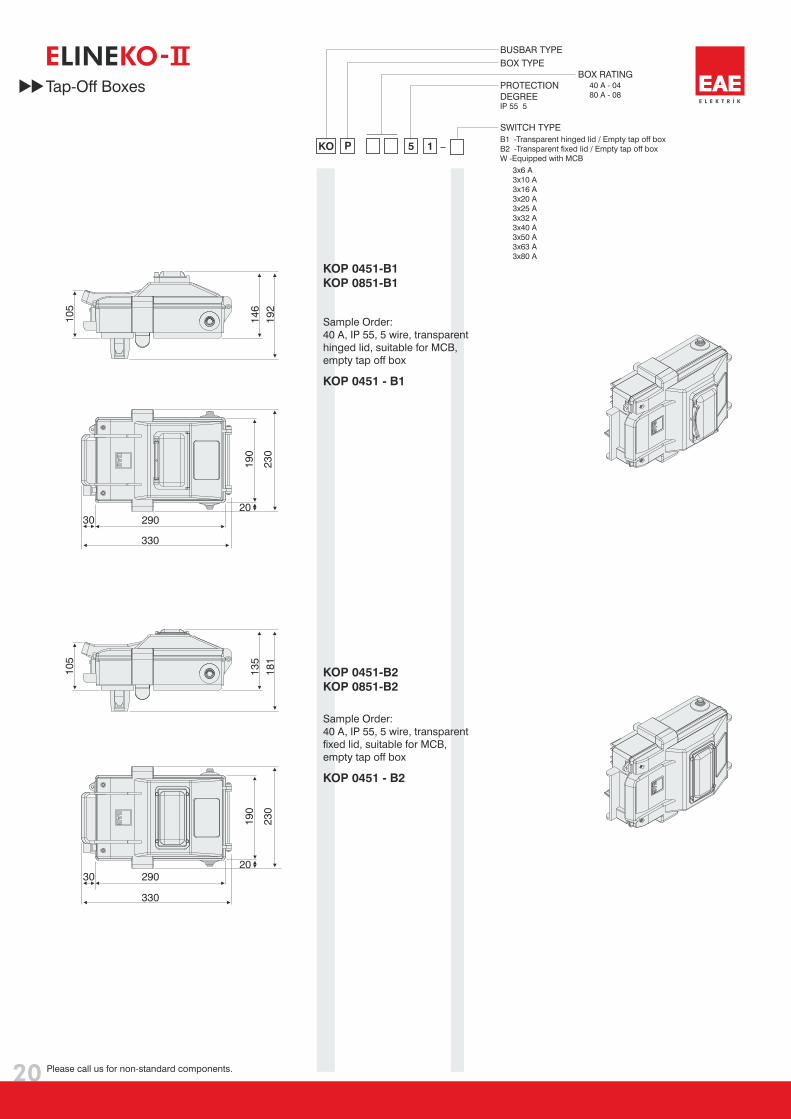
KO 15P
BUSBAR TYPE
BOX TYPE
BOX RATINGPROTECTION
DEGREE
SWITCH TYPE
IP 55 5
B1 -Transparent hinged lid / Empty tap off box
B2 -Transparent fixed lid / Empty tap off box
W -Equipped with MCB
40 A - 04
80 A - 08
3x6 A
3x10 A
3x16 A
3x20 A
3x25 A
3x32 A
3x40 A
3x50 A
3x63 A
3x80 A
1
1
KOP 045 -B1
KOP 085 -B1
KOP 0451-B
KOP 0851-B
2
2
20
Tap-Off Boxes
Sample Order:
40 A, IP 55, 5 wire, transparent
hinged lid, suitable for MCB,
empty tap off box
Sample Order:
40 A, IP 55, 5 wire, transparent
fixed lid, suitable for MCB,
empty tap off box
KOP 0451 - B1
KOP 0451 - B2
13
5
18
1
10
5
23
0
20
19
0
30
330
290
23
0
20
19
0
30
330
14
6
19
2
10
5
290
E KO-LINE
Extension
Part
Threaded
Rod
Steel Nut
Washer
21
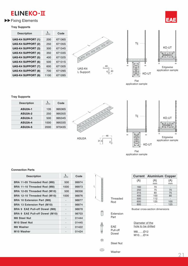
Fixing Elements
E KO-LINE
Current Aluminium Copper
(A) (A)mm
(A)mm
-707580-
100125
707580
100112125
-
160250315400500600800
EAE
Pull-off
Dowel
Diameter of the
hole to be drilled
Busbar cross-section dimensions
ASU2A
KO-UT
Tij
TijKO-UT
KO-UT
KO-UT
UAS-K4
L Support
M8.......Ø12
M10.....Ø14
L
Tray Supports
Tray Supports
CodeL(mm)
ASU2A-1
ASU2A-2
ASU2A-3
ASU2A-4
ASU2A-5
Description
99536S
99535S
99534S
99533S
97043S
CodeL(mm)
UAS-K4 SUPPORT (1)
UAS-K4 SUPPORT (2)
UAS-K4 SUPPORT (3)
UAS-K4 SUPPORT (4)
UAS-K4 SUPPORT (5)
UAS-K4 SUPPORT (6)
UAS-K4 SUPPORT (7)
UAS-K4 SUPPORT (8)
UAS-K4 SUPPORT (9)
Description
67136S
67135S
67134S
67133S
67132S
67131S
67130S
67129S
67128S
200
250
300
350
400
500
600
700
1100
135
250
500
1000
2000
Connection Parts
CodeL(mm)
BRA 11-05 Threaded Rod (M8)
BRA 11-10 Threaded Rod (M8)
BRA 12-05 Threaded Rod (M10)
BRA 12-10 Threaded Rod (M10)
Description
99974
99973
99356
98876
500
1000
500
1000
40
40
L
L
4
BRA 10 Extension Part (M8)
BRA 13 Extension Part (M10)
BRA 9 EAE Pull-off Dowel (M8)
BRA 9 EAE Pull-off Dowel (M10)
M8 Steel Nut
M10 Steel Nut
M8 Washer
M10 Washer
-
-
-
-
-
-
-
-
98877
98874
98878
98703
01444
01445
01422
01424
31,5
46
2
Flat
application sample
Flat
application sample
Edgewise
application sample
Edgewise
application sample

22
Fixing Elements
E KO-LINE
Vertical Support Set
Wall Type
Vertical Support Set
(Z) Type
Vertical Support Set
(VS) Type
Code
Vertical Support Set Wall Type
Description
66916
Code
Vertical Support Set (Z) Type
Description
91202
CodeCurrent A(mm)
KOA - 1 UT Clamp
KOA - 2 UT Clamp
KOA - 3 UT Clamp
KOA - 4 UT Clamp
KOA - 5 UT Clamp
KOA - 6 UT Clamp
KOC - 2 UT Clamp
KOC - 4 UT Clamp
KOC - 6 UT Clamp
KOC - 8 UT Clamp
Description
97524
97527
97523
97526
97385
97525
97524
97523
97526
97525
160
250
315
400
500
600
250
400
600
800
115
120
125
145
157
170
115
125
145
170
Code
Vertical Support Set (VS)-40
Vertical Support Set (VS)-60
Description
96017
95996
A(mm)
40
60
KO-UT
Clamp
TMP 8
ASU2A
KT
90
10x30
A
TS
25
11x16
7x16
A
90
13x35
10,5x35
30
A
235
A
90
4
13
5
7,5
12
25
125155
10
5
Ø10
14x20
15x35
12x20
70
75
KT 200 Tray Support
KT 250 Tray Support
KT 300 Tray Support
KT 400 Tray Support
KT 500 Tray Support
KT 600 Tray Support
TS 200 Tray Support
TS 200 Tray Support
TS 200 Tray Support
TS 200 Tray Support
TS 200 Tray Support
TS 200 Tray Support
TMP 8 Ceiling Support Unit
Coupling
99525S
99524S
99523S
99522S
99521S
98715S
99517S
99516S
99515S
99514S
99513S
67876S
99196S
98869
A(mm)
235
285
335
435
535
635
205
255
305
405
505
605
-
-
Coupling
CodeDescription
Ø13Ø11Ø9
Ø1010x20
42,5
35
23
10
0
100
10
01
00
100
100
10
0
50
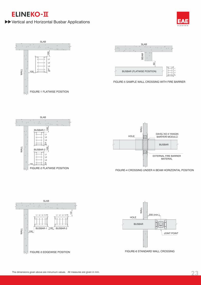
BUSBAR
DAHİLİ KO-II YANGIN
BARİYERİ MODULÜ
200 (min.)
100
E KO-LINE
L1
L2
L3
NPE
L1
L1
L2
L2
L3
L3
N
N
PE
PE
L1
L2
L3
NPE
L1 L2 L3 N PE L1 L2 L3 N PE
Vertical and Horizontal Busbar Applications
SLAB
WA
LL
FIGURE-1 FLATWISE POSITION
SLAB
BE
AM
FIGURE-4 CROSSING UNDER A BEAM HORIZONTAL POSITION
BUSBAR (FLATWISE POSITION)
SLAB
WA
LL
FIGURE-2 FLATWISE POSITION
BUSBAR-1
BUSBAR-2
SLAB
WA
LL
FIGURE-3 EDGEWISE POSITION
BUSBAR-1 BUSBAR-2
All measures are given in mm.The dimensions given above are minumum values.
WA
LL
JOINT POINT
HOLE
FIGURE-6 STANDARD WALL CROSSING
BUSBAR
WA
LL
HOLE
FIGURE-5 SAMPLE WALL CROSSING WITH FIRE BARRIER
EXTERNAL FIRE BARRIER
MATERIAL
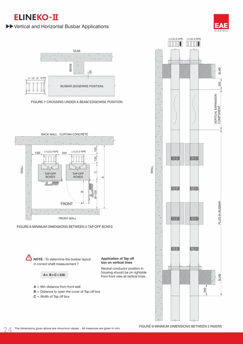
24
20
FRONT WALL
200
100
130
C
B
150
20
0
20
0
A
B
C
A= B+C+330
= Min distance from front wall
Distance to open the cover of Tap off box
Width of Tap off box
=
=
L1
L1L1
L1L2
L2L2
L2L3
L3L3
L3N
NN
NPE
PEPE
PE
Application of Tap off
box on vertical lines
Neutral conductor position in
housing should be on rightside
from front view at vertical lines.
FRONT
L1 L2 L3 N PE
E KO-LINE
B+
100
A
Vertical and Horizontal Busbar Applications
SLAB
BE
AM
FIGURE-7 CROSSING UNDER A BEAM EDGEWISE POSITION
BUSBAR (EDGEWISE POSITION)
BACK WALL - CURTAIN CONCRETE
WA
LL
BOXES
FIGURE-8 MINIMUM DIMENSIONS BETWEEN 2 TAP-OFF BOXES
TAP-OFFBOXES
TAP-OFF
SLA
B
FIGURE-9 MINIMUM DIMENSIONS BETWEEN 2 RISERS
VE
RT
ICA
L E
XP
AN
SIO
N
CO
MP
ON
EN
TP
LU
G-I
N B
US
BA
RS
LA
B
WA
LL
All measures are given in mm.The dimensions given above are minumum values.
NOTE : To determine the busbar layout
in correct shaft measurement ?
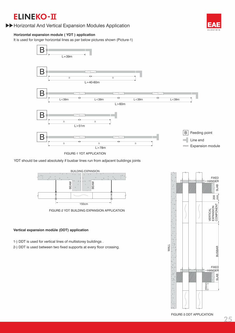
BL=39m
BL=40-60m
BL>51m
BL>78m
B
B
L>60m
L<39m L<39m L<39m L<39m
FIXED
HANGER
FIXED
HANGER
20
0m
m
20
0
mm
BU
SB
AR
25
Horizontal And Vertical Expansion Modules Application
Horizontal expansion module ( YDT ) application
Vertical expansion modüle (DDT) application
E KO-LINE
It is used for longer horizontal lines as per below pictures shown (Picture-1)
YDT should be used absolutely if busbar lines run from adjacent buildings joints
Feeding point
Line end
Expansion module
1-) DDT is used for vertical lines of multistorey buildings .
) DDT is used between two fixed supports at every floor crossing.2-
150cm
BUILDING EXPANSION
FIGURE-3 DDT APPLICATION
FIGURE-2 YDT BUILDING EXPANSION APPLICATION
FIGURE-1 YDT APPLICATION
SLA
BS
LA
B
VE
RT
ICA
L
EX
PA
NS
ION
CO
MP
ON
EN
T
WA
LL
BE
AM
BE
AM

Fire Barriers
Dimensioning of Fire Barrier
KO-
Fire barriers are used to prevent the transition of flame and smoke
from one zone to another in case of fire. Chimney effect of air
insulated busbars are diminished.
While placing an order for fire barriers that will be installed into Busbar
below listed information should be given:
1- Thickness of floor or wall in cm. (A cm)
2- Centerline dimension of the fire barrier should be measured from the side
without the block joint. (Y cm)
3- There will be no plug-in points at fire barrier location.
4- EAE Supplies 30 cm thick fire barrier as standard when wall or floor
thickness is not stated.
5- The minimum length for these special elements with fire barrier can be 60cm.
1
2
A
Y
FloorSample Order:
250 A, Copper, IP 55, 5 Conductors
Fire Barrier
KOC 0255- -STD-150-40Fire
Barrier
Block Joint
Please call us for more information.
N
26
Fire Barriers
After installation of standard busbar 3m lengths, you will be in need of special lengths which are smaller then 3m.
The minimum length for these special elements can be 35 cm. Please measure the lengths of these modules as shown below.
Determination of Special Lengths
A
E KO-LINE
A (cm): Thickness of Fire Barrier
Y (cm): Centerline of Fire Barrier
KO B
BUSBAR TYPE
CONDUCOR TYPE
BUSBAR CODE
PROTECTION DEGREE
NUMBER OF CONDUCTORS
COMPONENT
UNPAINTED / PAINTED
Y DIMENSION
A DIMENSION
Measure “A” length in cm, to determine the length of
special busbar subtract 12 from “A”.
X=A-12 (cm) X=Length of Special Busbar
Fire B
arr
ier

27
E KO-LINE
3
8
55 Nm (40lbft)
7
65
21
2a
1a
1a
4
1
4
2
1
2
3
4
5 1
2
3
4
3
1
2
3
4
6
1-
. (Pieces marked as 1a shall be
thrown away.)
Remove joint top cover plate, joint side
cover plate and the screws from non-block
joint bolt
2-
.
Introduce bolted and non-bolted ends of
the busbar into each other carefully, till joint
side cover plate screws can be put on
3-
.
Fix the joint side cover of the block
joint
4- Tighten the double headed
nut untill upper nut is broken.
7-
or
Ensure that the insulation
plates of the joint, are not
cracked broken.
8- If removal is required for any reason,
tighten nut by calibrated torque wrench
adjusted to 55 Nm (40 lbft) after re-fixing
block joint set.
6-
-II .
Install top and bottom joint cover plates. Check the joint
before fitting the last joint side cover plate. Fit the joint cover
side plate and tighten and screws. Check the position of the
earth conductor when installing KO with five conductors
5- Take away the broken nut
and plastic seperator.
Figure 3
KO- Installation of End Closer
KO- Mounting instructions for Joints

28
E L E K T R İ K
Directive
EAE Elektrik A.S.
EC DECLARATION OF CONFORMITY
Product Group
Standard :
Manufacturer
E-Line KO-II Busbar Energy Distribution System
IEC 60439-1
IEC 60439-2
EAE Elektrik Asansor End. Insaat San. ve Tic. A.S.
EAE Elektrik Asansor End. Insaat San. ve Tic. A.S.
This is to attest, under our sole responsibility, that the aforementioned products conforms with
the regulations and guidelines of the following standards.
Date
11.09.2002
According to EC - Directive
2006/95/EEC “Low - Voltage - Directive”
E KO-LINE
Akcaburgaz Mahallesi, 119. Sokak, No:10 34510 Esenyurt-Istanbul
Tel: +90 (212) 866 20 00 Fax: +90 (212) 886 24 20 www.eae.com.tr
Akcaburgaz Mahallesi, 119. Sokak,
No:10 34510 Esenyurt-Istanbul
Tests
1- Temperature-rise Limits (8.2.1)
2- Dielectric Properties (8.2.2)
3- Short-circuit Strength (8.2.3)
4- Effectiveness of The Protective Circuit (8.2.4)
5- Clearances and Creepage Distances (8.2.5)
6- Mechanical Operation (8.2.6)
7- Degree of Protection (8.2.7)
8- Electrical Characteristics (8.2.9)
9- Structural Strength (8.2.10)
10- Crushing Resistance (8.2.12)
11- Resistance of Insulating Materials
to Abnormal Heat (8.2.13)
12- Resistance to Flame-propagation (8.2.14)
13- Fire Barrier (8.2.15)

29
E KO-LINECertificates

30
Product Overview
160A 800A BUSBAR SYSTEM
PRODUCT OVERVIEW (E-LINE KO-II)
Standards & Certification:- Busbar system shall be designed and manufactured as per IEC 60439-2 standard. Each individual rated busbar shall have separate type test certificate from an independentinternationally accredited laboratory.-- Busbar system shall have CE marking.- Each product shall have a “Type Label”, which indicates the brand, type of the unit, conductor number and electrical details.
Manufacturing facility of busbar systems shall have ISO 9001 and ISO 14001 certification.
Joint Structure:- Electrical and mechanical connection shall be made at joints by “single bolt” joint construction and each joint shall have two “Belleville” washers.- Insulators of the joint shall be manufactured of glass-reinforced polyester.- Joints shall be realized by a torque spanner (wrench) set at 55 Nm.- To prevent the joints from transportation damages, they shall be protected by metal caps, which shall be removed before installation.- Joint bolt shall be locked from both sides (Bolt head and nut).
Tap Off Boxes:- Rating of plug-in tap off boxes shall be up to and including 400A. Plug-in tap off boxes shall be installed, when the busbar line is energized.- Tap off boxes shall have an electrical interlock mechanism, which ensures that plug-in tap off box cannot be removed mechanically from the busbar, when the switch is at “ON”position. Mechanical interlock mechanism shall prevent the cover of the box from opening, when the switch is at “ON” position.- When the switch is at “OFF” position and the cover is open, tap off box shall provide IP2X protection level. (There shall not be any accessible live part in the box).- Tap Off boxes shall be suitable for any brand of MCB.- Contacts of plug-in tap off box shall be silver-plated copper.- While inserting the contacts of Plug-in tap off boxes, earth contact shall make first contact.- Tap off boxes up to 80A shall be manufactured of (850 GLW) type plastic material. Tap off boxes from 160A up to 400A shall be manufactured of sheet steel and epoxy paintedRAL 3020.
Installation and Commissioning:- Busbar systems shall be installed as per single-Line drawings respect to required ampere rates and manufacturer installation guide (torque values, lockers, etc.).Electrical installer shall run an insulation test after installation according to manufacturer's test procedures. The results of the test shall be reported to the manufacturer.Minimum insulation value shall be 1Mohm.
Housing and Structure:- Busbar system shall be of air insulated type. The bars shall be supported by insulators installed into the housing at every 25 cm.- On a three meter standard length busbar the distance between the plug-in points on one side shall be 50cms. The points shall be on both sides of the busbar making theaverage distance of plug-in points 25cm.- To prevent wrong alignment of the phase sequence during installation there shall be mechanical barriers on the joint that shall ensure correct mounting.- IP Plug-in covers of the busbar system should be hinged.Plug-in windows shall have automatic shutter system. This shutter shall open automatically when the earth contact oftap-off box is inserted.- Busbar system shall have all necessary accessories (elbows, offsets, panel-transformer connections, reductions, etc). Manufacturer shall supply special dimensioned units inshort time, if the project conditions requires.- For horizontal runs, a horizontal expansion unit shall be used at every 40m and expansion points of the building.- For vertical applications, a vertical expansion unit shall be used at every floor. Busbar system shall be rigidly fixed by supports at every floor.
General Structure of Products:- Busbar system shall be Air-Insulated and Plug-in type. Aluminium or Copper conductors shall be tin plated along the entire length. Housing shall be galvanized steel or if requiredRAL7038-Electrostatic painted.
Electrical Characteristics:
-
- Busbar systems nominal insulation voltage shall be 1000V.- As per ampere rates, minimum short circuit values shall be like below;
Temperature rise shall be maximum 50K over 40°C ambient temperaturefor both tin plated Aluminium and Copper conductor busbars.
Conductors:- Busbar system shall have Nickel and Tin-plated 6101 class aluminium conductors (160-600A). / Busbar system shall have Tin-plated Electrolytic copper conductors (250-800A).- Busbar system shall have below number of conductors and phase configuration;
a) 4 Conductors:(4 full size conductors + Housing ( earthing )b) (4 full size conductors + ½ earth conductor + Housing)c) ( 5 full size conductors + Housing (earthing) )d) ( 5 full size conductors, 5th bar shall be used as clean earth + Housing).
- Neutral conductor shall have the same cross-section (100%) of phase conductors.
4 ½ Conductors :
5 Conductors :
5 Conductors :
Insulation:- Busbars shall have air-insulation system.- Rated insulation voltage of the system shall be 1000 V.
Protection:- Protection degree of the busbar system shall be minimum IP55.
1-
2-
2.1-
2.2-
2.3-
2.4-
2.5-
2.6-
3-
4-
1sec/rms-10kA, Peak-17kA1sec/rms-15kA, Peak-30kA1sec/rms-30kA, Peak-63kA1sec/rms-35kA, Peak-73,5kA
160A:250 and 315A:400 and 500A:
600A and above:
E KO-LINE
31
Quantit
yC
om
po
nen
t
Co
mp
on
en
t Lis
t
Item
Project Design Form
E L E K T R İ K
E KO-IILINE
Ple
ase d
ub
licate
th
is p
ag
e fo
r yo
ur
ow
n u
se.
Nam
e:
Date
:
Sig
natu
re:
Prepared by
Co
mp
an
y:
Pro
ject
:
Pro
ject
No
:
32
Quantit
yC
om
po
nen
t
Co
mp
on
en
t Lis
t
Item
Project Design Form
E L E K T R İ K
E KO-IILINE
Ple
ase d
ub
licate
th
is p
ag
e fo
r yo
ur
ow
n u
se.
Nam
e:
Date
:
Sig
natu
re:
Prepared by
Co
mp
an
y:
Pro
ject
:
Pro
ject
No
:

PRODUCTTYPES
Compact Busbar Distribution System800...6300A
Plug-in Busbar Distribution System160...800A
Small Power Plug-in Busbar Distribution System100-160-225A
Plug-in Busbar Distribution System40-63A
Multi-conductor Lighting Busbar System25-32-40A
Lighting Busbar System25-32-40A
Multi Conductor Trolley Busbar System35...250A
Underfloor Ducting Systems
Raised Floor Energy Distribution Systems25...63A
CableTray Systems
E-LINE KB
E-LINE MK
E-LINE KAP
E-LINE DL
E-LINE KAM
E-LINE TB
E-LINE DK
E-LINE DKY
E-LINE UK

www.eae.com.trA
TA
MA
TB
AA
CIL
IK /
A.C
.E./
61
2 4
0 6
6Akçaburgaz Mahallesi,
119. Sokak, No:10 34510
Esenyurt-Istanbul-TURKEY
Tel: +90 (212) 886 20 00
Fax: +90 (212) 886 24 20
T E
ME 04
IEC 60439-2 sISO9001
14001
QUALIT
YA
ND
ENVI
RONMENTAL MANAGEM
EN
TS
YSTEM
S
EA
E h
as
full
rig
ht
to m
ake
an
y re
visi
on
s o
r ch
an
ges
on
th
is c
ata
log
ue w
itho
ut
an
y p
rio
r n
otic
e.
Cata
log
ue
13-E
ng
. /
02
1000 P
cs
07/1
2/2
011