Burny 10 LCD Plus Operator Guide
38
BURNY 10 LCD PLUS OPERATOR’S GUIDE (AO-70247 REV AA) AA REVISION
-
Upload
nguyen-quyet-thang -
Category
Documents
-
view
1.038 -
download
40
Transcript of Burny 10 LCD Plus Operator Guide

BURNY 10 LCD PLUS OPERATOR’S GUIDE
(AO-70247 REV AA)
AAREVISION
BURNY 10 LCD PLUS: OPERATOR’S GUIDE AO-70247 REV AA
PAGE 2 OF 38
REVISION HISTORY
Rev ECO Author Date Description of Change AA BMA 08/03 As Released
DOCUMENTATION OVERVIEW
This document provides step-by-step instructions required for typical day-to-day use of the BURNY 10 LCD Plus. More detailed information is available by consulting the appropriate Operation and Maintenance manual contained on the CD-ROM that shipped with this product.
Due to the variety of ways the BURNY 10 LCD Plus can be incorporated onto a cutting machine, a specific startup sequence has NOT been included. Please refer to the documentation provided by the original cutting machine manufacturer for details.
If you have any comments or suggestions about our documentation please contact our customer support team at 1-800-321-8072.
FURTHER INFORMATION
We are constantly striving to improve our products. As a result, the contents of this document may change without notification. Please visit our website (www.burny.com) to download the most recent version and to keep up with the latest in PC-based CNC control technology.
Cleveland Motion Controls, Inc. reserves the right to change the content and product specification without notice.
© 2003 in this document is reserved to: Cleveland Motion Controls, Inc.
7550 Hub Parkway
Cleveland, OH 44125
216-524-8800 Phone
216-642-2199 Fax
AO-70247 REV AA BURNY 10 LCD PLUS: OPERATOR’S GUIDE
PAGE 3 OF 38
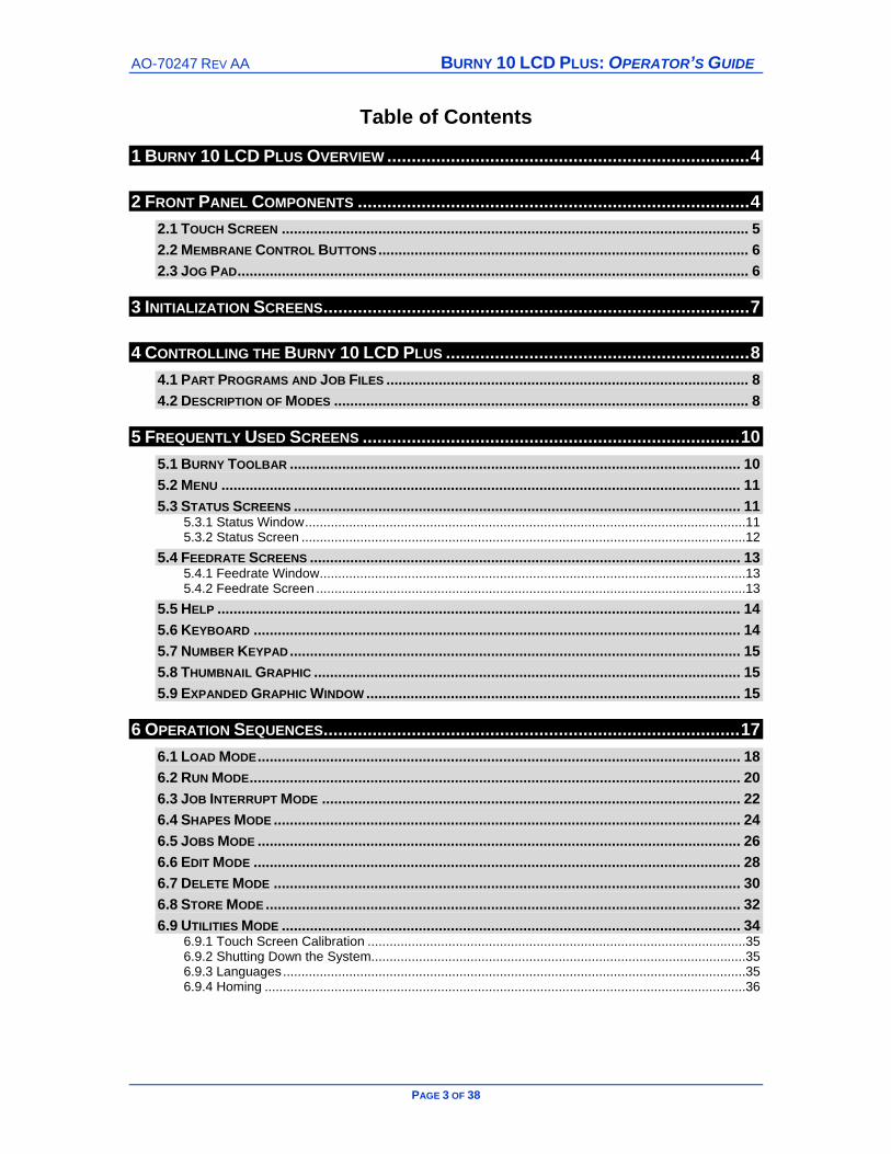
Table of Contents
1 BURNY 10 LCD PLUS OVERVIEW ..........................................................................4
2 FRONT PANEL COMPONENTS ................................................................................4 2.1 TOUCH SCREEN .................................................................................................................... 5 2.2 MEMBRANE CONTROL BUTTONS............................................................................................ 6 2.3 JOG PAD............................................................................................................................... 6
3 INITIALIZATION SCREENS.......................................................................................7
4 CONTROLLING THE BURNY 10 LCD PLUS ..............................................................8 4.1 PART PROGRAMS AND JOB FILES .......................................................................................... 8 4.2 DESCRIPTION OF MODES ....................................................................................................... 8
5 FREQUENTLY USED SCREENS .............................................................................10 5.1 BURNY TOOLBAR ................................................................................................................ 10 5.2 MENU ................................................................................................................................. 11 5.3 STATUS SCREENS ............................................................................................................... 11
5.3.1 Status Window........................................................................................................................11 5.3.2 Status Screen .........................................................................................................................12
5.4 FEEDRATE SCREENS ........................................................................................................... 13 5.4.1 Feedrate Window....................................................................................................................13 5.4.2 Feedrate Screen .....................................................................................................................13
5.5 HELP .................................................................................................................................. 14 5.6 KEYBOARD ......................................................................................................................... 14 5.7 NUMBER KEYPAD................................................................................................................ 15 5.8 THUMBNAIL GRAPHIC .......................................................................................................... 15 5.9 EXPANDED GRAPHIC WINDOW ............................................................................................. 15
6 OPERATION SEQUENCES.....................................................................................17 6.1 LOAD MODE........................................................................................................................ 18 6.2 RUN MODE.......................................................................................................................... 20 6.3 JOB INTERRUPT MODE ........................................................................................................ 22 6.4 SHAPES MODE .................................................................................................................... 24 6.5 JOBS MODE ........................................................................................................................ 26 6.6 EDIT MODE ......................................................................................................................... 28 6.7 DELETE MODE .................................................................................................................... 30 6.8 STORE MODE ...................................................................................................................... 32 6.9 UTILITIES MODE .................................................................................................................. 34
6.9.1 Touch Screen Calibration .......................................................................................................35 6.9.2 Shutting Down the System......................................................................................................35 6.9.3 Languages..............................................................................................................................35 6.9.4 Homing ...................................................................................................................................36
BURNY 10 LCD PLUS: OPERATOR’S GUIDE AO-70247 REV AA
PAGE 4 OF 38
1 BURNY 10 LCD PLUS OVERVIEW
Welcome to the most advanced PC-based CNC Controller—the BURNY 10 LCD Plus. As a retrofit or on a new machine the BURNY 10 LCD Plus provides extremely stable and accurate real-time motion control for a variety of cutting processes including: Oxy-Fuel, Plasma, Laser, Waterjet, and Routers.
The BURNY 10 LCD Plus is engineered for X-Y axis cutting machines and accepts virtually all part program formats. Designed with an industrial grade Touch-Screen and running on Windows® NT Embedded® technology, the BURNY 10 LCD Plus allows the operator to maximize productivity by performing tasks quickly and in most cases, simultaneously.
The BURNY 10 LCD Plus is truly powerful, yet easy to use. Major functions are intuitive and easy to find, however on-screen help is available at the touch of a button.
This guide is a supplement to the BURNY 10 Series Operation and Maintenance Manuals, for detailed descriptions of the various modes and operation of the system please refer to these manuals.
Again, welcome to BURNY!
2 FRONT PANEL COMPONENTS
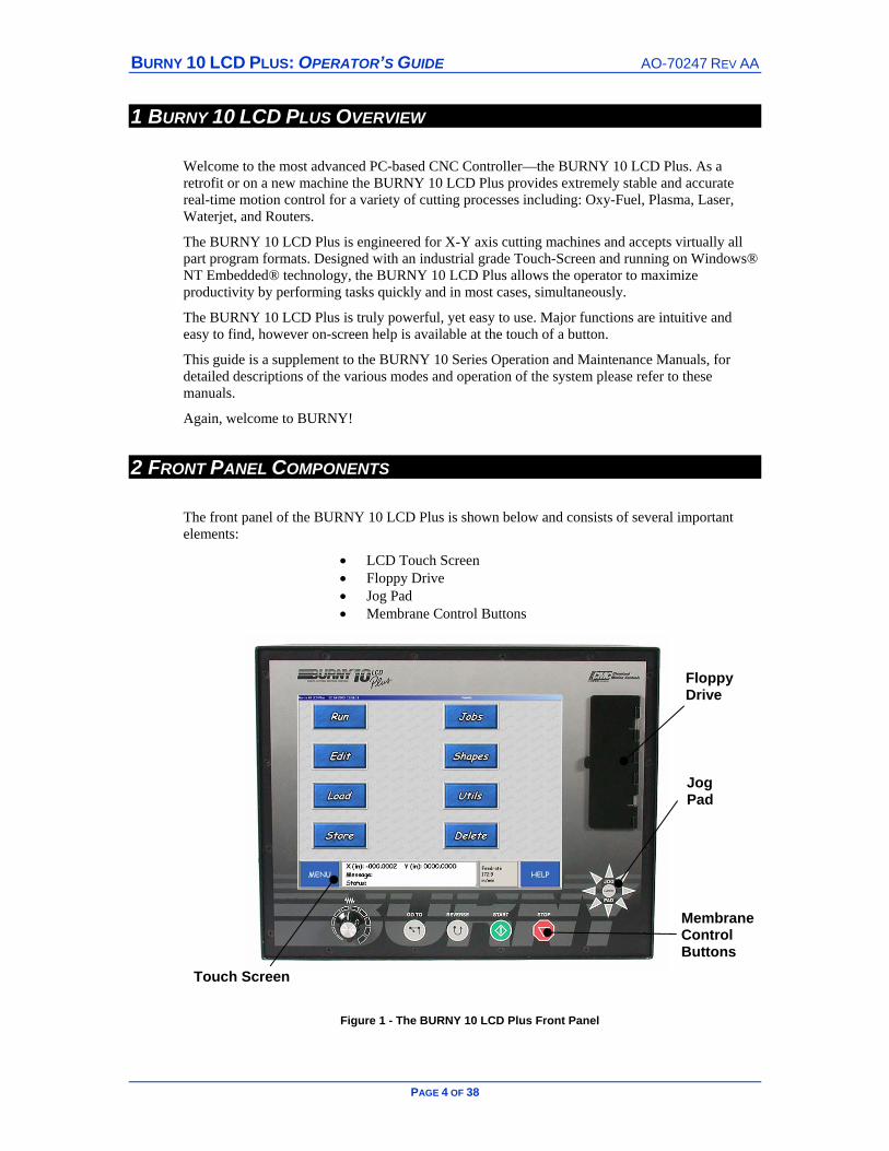
The front panel of the BURNY 10 LCD Plus is shown below and consists of several important elements:
• LCD Touch Screen • Floppy Drive • Jog Pad • Membrane Control Buttons
Figure 1 - The BURNY 10 LCD Plus Front Panel
Floppy Drive
Jog Pad
Membrane Control Buttons
Touch Screen

AO-70247 REV AA BURNY 10 LCD PLUS: OPERATOR’S GUIDE
PAGE 5 OF 38
2.1 TOUCH SCREEN
The touch sensitive LCD screen allows the operator to monitor and control the BURNY. Most functions and features are intuitive.
Figure 2 - The LCD Touch Screen
Titlebar - Displays the Date, Time, current Screen Name and notification if the password is enabled.
Thumbnail Graphic – press to view the Expanded Graphic Window showing the part in greater detail. Refer to Section 5.8
Scroll Buttons – press to scroll up or down a list. The selected filename will be highlighted.
Button - touch sensitive area on the screen. Press firmly to activate the button and display the associated screen or function.
BURNY Toolbar – used to view the Menu, Help, Status and Feedrate Screens – it is common to every screen – Refer to Section 5.1 for further information.
Titlebar
Thumbnail Graphic
Scroll Buttons
Button
BURNY Toolbar
Button

BURNY 10 LCD PLUS: OPERATOR’S GUIDE AO-70247 REV AA
PAGE 6 OF 38
2.2 MEMBRANE CONTROL BUTTONS
Figure 3 - Membrane Control Buttons
GO TO – used to move to pre-defined places in the active part program or to home table positions. Refer to section 6.3 Job Interrupt Mode for more information.
REVERSE – used to backtrack along the cutting path as long as the button is depressed. The cut process is stopped during Reverse. Press the Cycle Start Membrane button to restart cutting.
CYCLE START GO – press to start the cutting operation.
CYCLE STOP – press to stop the cutting process or current motion activity.
2.3 JOG PAD
Figure 4 - The Jog Pad
Pressing the Jog Pad buttons moves the cutting tool in any of the eight directions indicated and will continue to move in that direction for as long as the button is held down. The direction of travel can be “locked” by first pressing the Latch Jog Button followed by the required direction. The motion will continue until one of the following:
• Stop button is pressed
• The machine stop/limit is reached
Latch Jog Button
AO-70247 REV AA BURNY 10 LCD PLUS: OPERATOR’S GUIDE
PAGE 7 OF 38
3 INITIALIZATION SCREENS
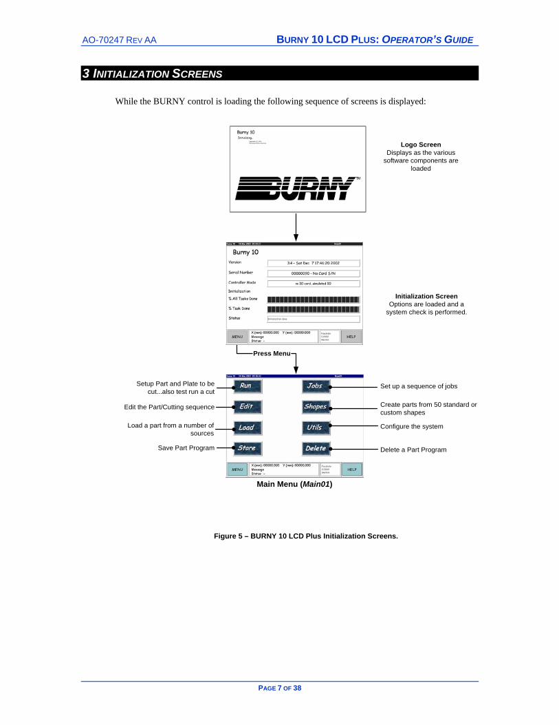
While the BURNY control is loading the following sequence of screens is displayed:
Set up a sequence of jobs
Create parts from 50 standard orcustom shapes
Configure the system
Delete a Part Program
Setup Part and Plate to becut...also test run a cut
Edit the Part/Cutting sequence
Load a part from a number ofsources
Save Part Program
Logo ScreenDisplays as the various
software components areloaded
Initialization ScreenOptions are loaded and a
system check is performed.
Main Menu (Main01)
Press Menu
Figure 5 – BURNY 10 LCD Plus Initialization Screens.
BURNY 10 LCD PLUS: OPERATOR’S GUIDE AO-70247 REV AA
PAGE 8 OF 38
4 CONTROLLING THE BURNY 10 LCD PLUS
The BURNY comprises of two main functions preparing the part program to be cut and the cutting process. :
Preparing the part program – the part programs are either uploaded or created using the Shapes mode. The cutting process information is added, i.e. cutting speed, kerf etc. and the job is now ready to be cut.
Cutting the part - started and stopped using the physical controls on the Control Panel.
4.1 PART PROGRAMS AND JOB FILES The files that control the shape to be cut are of two types: A Part Program and a Job File.
A Part program contains the information required to construct a part such as dimensions, geometry information etc.
A Job is a file that contains both the Part Program information along with the operating conditions required to produce the part such as cut speed, kerf, geometric orientation, scaling, rotation, plate dimension and location, process type, process timers etc.
The operating conditions can be added to the part program via two screens – the Run Setup Screen (Run02) if the part is to be run immediately or the Job Setup Screen (Job04) where the operator can specify the federates, kerf etc. for a job that will be cut in the future.
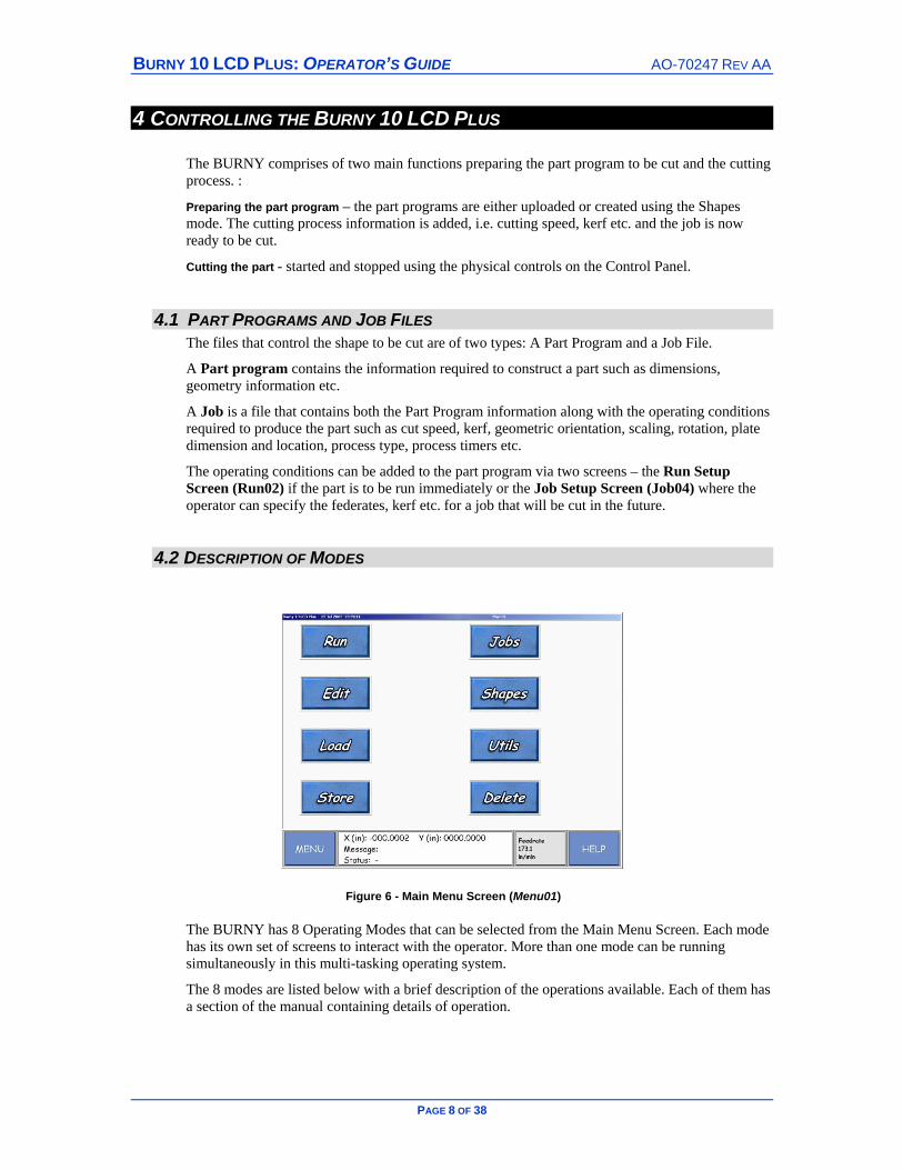
4.2 DESCRIPTION OF MODES
Figure 6 - Main Menu Screen (Menu01)
The BURNY has 8 Operating Modes that can be selected from the Main Menu Screen. Each mode has its own set of screens to interact with the operator. More than one mode can be running simultaneously in this multi-tasking operating system.
The 8 modes are listed below with a brief description of the operations available. Each of them has a section of the manual containing details of operation.

AO-70247 REV AA BURNY 10 LCD PLUS: OPERATOR’S GUIDE
PAGE 9 OF 38
RUN Pick part program Set up part program and plate Test Run Cut Part
EDIT* Edit an existing part program, custom shape, or ASCII file. Write new part program
LOAD Select source device Select folder Select part program Select destination directory Copy file to the Burny 10, with conversion for part programs
STORE Select destination device Select source directory (File Type) Select file Select destination folder (depends on destination device) Select output code conversion (part programs)
JOBS Put a part program on the Job List by setting it up Examine and modify details of a part program on the Job List Remove a job from the Job List
SHAPES Create part program from one of 50 standard generic shapes Create part program from a custom generic shape
UTILITIES Examine the value of Control parameters Change the value of Control parameters Setup the machine by tuning Control parameters
DELETE* Delete a file from the Part Programs, ASCII, Aux Code, CAD Configuration, or Custom Shapes directory Delete a file from a floppy in the drive
*Can’t be performed while cutting.
BURNY 10 LCD PLUS: OPERATOR’S GUIDE AO-70247 REV AA
PAGE 10 OF 38
5 FREQUENTLY USED SCREENS A number of screens are used frequently throughout the BURNY, including::
• BURNY Toolbar
• Main Menu Screen
• Help Screen
• Status Screen
• Feedrate Screen
• Keyboard Screen
• Number Pad Screen
• Thumbnail and Expanded Graphic Windows
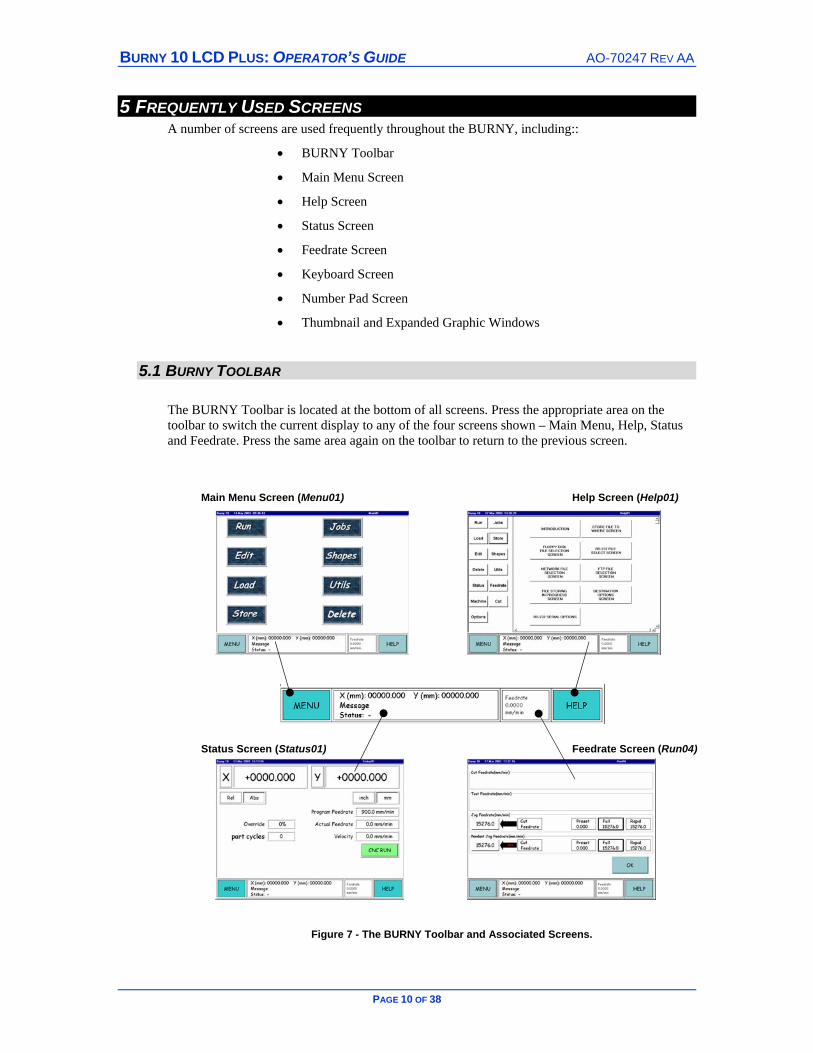
5.1 BURNY TOOLBAR
The BURNY Toolbar is located at the bottom of all screens. Press the appropriate area on the toolbar to switch the current display to any of the four screens shown – Main Menu, Help, Status and Feedrate. Press the same area again on the toolbar to return to the previous screen.
Figure 7 - The BURNY Toolbar and Associated Screens.
Feedrate Screen (Run04)
Help Screen (Help01) Main Menu Screen (Menu01)
Status Screen (Status01)
AO-70247 REV AA BURNY 10 LCD PLUS: OPERATOR’S GUIDE
PAGE 11 OF 38
5.2 MENU
Press the MENU button to display the Main Menu Screen. Select from 8 Operating Modes to display the required screen. Pressing MENU twice displays the last screen active under Run mode. Refer to Section 4.2 for details on the 8 Operating Modes.
5.3 STATUS SCREENS
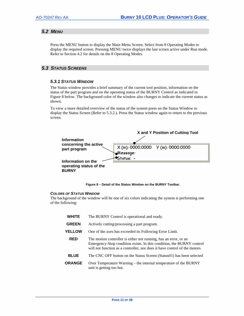
5.3.1 STATUS WINDOW The Status window provides a brief summary of the current tool position, information on the status of the part program and on the operating status of the BURNY Control as indicated in Figure 8 below. The background color of the window also changes to indicate the current status as shown.
To view a more detailed overview of the status of the system press on the Status Window to display the Status Screen (Refer to 5.3.2.). Press the Status window again to return to the previous screen.
Figure 8 – Detail of the Status Window on the BURNY Toolbar.
COLORS OF STATUS WINDOW The background of the window will be one of six colors indicating the system is performing one of the following:
WHITE The BURNY Control is operational and ready.
GREEN Actively cutting/processing a part program.
YELLOW One of the axes has exceeded its Following Error Limit.
RED The motion controller is either not running, has an error, or an Emergency-Stop condition exists. In this condition, the BURNY control will not function as a controller, nor does it have control of the motors.
BLUE The CNC OFF button on the Status Screen (Status01) has been selected
ORANGE Over Temperature Warning – the internal temperature of the BURNY unit is getting too hot.
X and Y Position of Cutting Tool
Information concerning the active part program
Information on the operating status of the BURNY

BURNY 10 LCD PLUS: OPERATOR’S GUIDE AO-70247 REV AA
PAGE 12 OF 38
5.3.2 STATUS SCREEN
The Status Screen (Status01) is accessed by pressing the Feedrate Window on the Burny Toolbar. This screen contains the X/Y position (Relative/Absolute, inches/mm), Feedrates, cutting program status message, and other items as shown in Figure 9. It also includes buttons to access additional Status information and clear the relative X/Y positions if no part program is currently running. The Status Screen has a button for toggling CNC ON or OFF – when turned off the BURNY is no longer in control of the cutting machine. Other buttons may be visible depending upon the optional features installed, press the button to access the option. Press the Status Window to return to the previous screen.
Figure 9 - Status Screen (Status01)

AO-70247 REV AA BURNY 10 LCD PLUS: OPERATOR’S GUIDE
PAGE 13 OF 38
5.4 FEEDRATE SCREENS
5.4.1 FEEDRATE WINDOW Displays the current speed of the tool along the traverse or cutting path while the part is being cut or during a GO TO move. If the Cycle Stop button is pressed when a job is cutting, the Run Mode Stop Screen appears. Pressing the Feedrate button at this point displays the Job Setup Screen where elements of the job can be changed. Press the Feedrate button to return to the Run Mode Stop screen, and press Cycle Start to restart the cutting process with the changes in effect. Details of the Feedrate button are covered below.
5.4.2 FEEDRATE SCREEN The Feedrate Screen (Run04) displays the cutting, jogging and test run feedrates, accessed by pressing the Feedrate Window on the BURNY Toolbar.
Figure 10 – The Feedrate Screen (Run04)
Use Embedded Feedrate – the feedrate has been configured during the part setup. Unless overridden it will be the default feedrate for the part. If Embedded has been configured then the Feedrate button on the Job Setup Screen (Run02) will be grayed out. Overriding the Embedded feedrate will cause the Cut Feedrate to be used.
Test Feedrate, Jog Feedrate and Pendant Jog Feedrate – these can be selected from any of up to five choices, to assign a rate press on the button – i.e. in Figure 10 the Test Feedrate has been set to Cut Feedrate and the Jog and Pendant Jog Feedrates are set to Full.
Cut Feedrate – a feedrate set by the operator or embedded in the part.
Program – the program feedrate is increased by a multiple of 1, 10, 100 or 1000 i.e. X10 = programmed feedrate multiplied by 10. Toggle to scroll through the list.
Preset – Operators preferred feedrate, press the button twice to bring up the number pad to enter the value.
Full – run at full speed of the system with override enabled
Rapid – a non-cutting move run at full speed of the system with override enabled
BURNY 10 LCD PLUS: OPERATOR’S GUIDE AO-70247 REV AA
PAGE 14 OF 38
5.5 HELP
Displays the online Help Screens, they are mode specific.
5.6 KEYBOARD
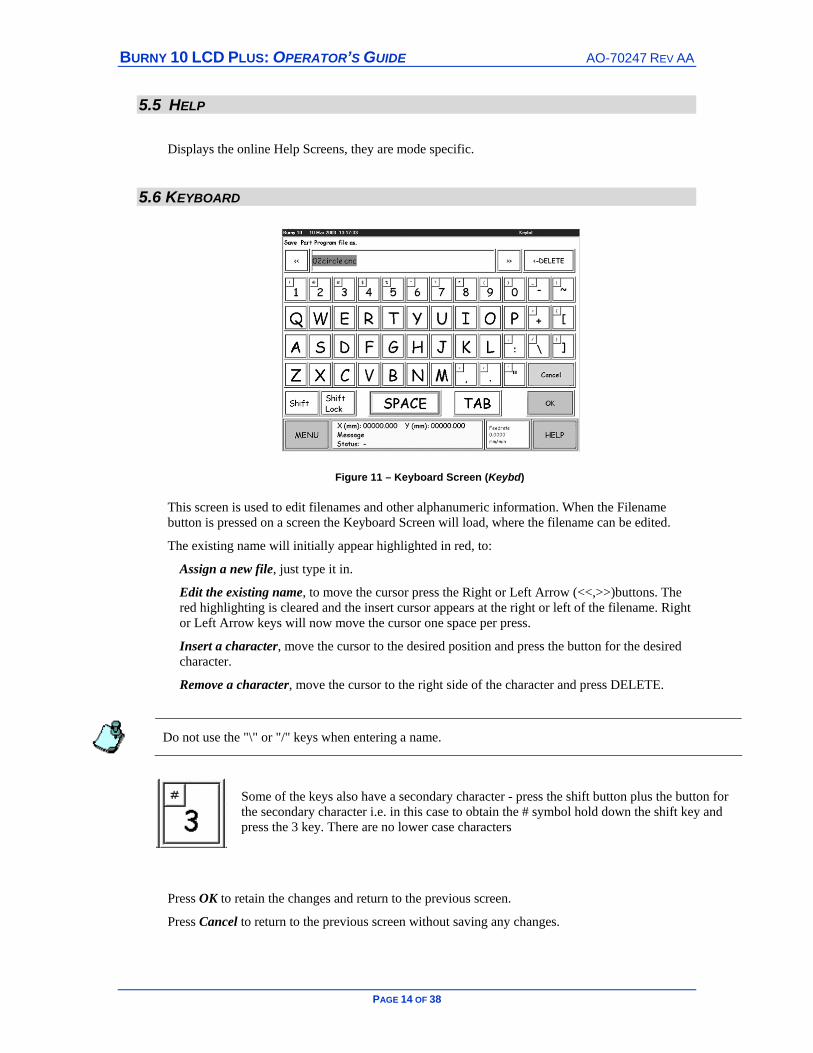
Figure 11 – Keyboard Screen (Keybd)
This screen is used to edit filenames and other alphanumeric information. When the Filename button is pressed on a screen the Keyboard Screen will load, where the filename can be edited.
The existing name will initially appear highlighted in red, to:
Assign a new file, just type it in.
Edit the existing name, to move the cursor press the Right or Left Arrow (<<,>>)buttons. The red highlighting is cleared and the insert cursor appears at the right or left of the filename. Right or Left Arrow keys will now move the cursor one space per press.
Insert a character, move the cursor to the desired position and press the button for the desired character.
Remove a character, move the cursor to the right side of the character and press DELETE.
Do not use the "\" or "/" keys when entering a name.
Some of the keys also have a secondary character - press the shift button plus the button for the secondary character i.e. in this case to obtain the # symbol hold down the shift key and press the 3 key. There are no lower case characters
Press OK to retain the changes and return to the previous screen.
Press Cancel to return to the previous screen without saving any changes.
AO-70247 REV AA BURNY 10 LCD PLUS: OPERATOR’S GUIDE
PAGE 15 OF 38
5.7 NUMBER KEYPAD
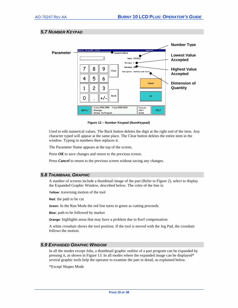
Figure 12 – Number Keypad (NumKeypad)
Used to edit numerical values. The Back button deletes the digit at the right end of the item. Any character typed will appear at the same place. The Clear button deletes the entire item in the window. Typing in numbers then replaces it.
The Parameter Name appears at the top of the screen.
Press OK to save changes and return to the previous screen.
Press Cancel to return to the previous screen without saving any changes.
5.8 THUMBNAIL GRAPHIC A number of screens include a thumbnail image of the part (Refer to Figure 2), select to display the Expanded Graphic Window, described below. The color of the line is:
Yellow: traversing motion of the tool
Red: the path to be cut
Green: In the Run Mode the red line turns to green as cutting proceeds.
Blue: path to be followed by marker
Orange: highlights areas that may have a problem due to Kerf compensation.
A white crosshair shows the tool position. If the tool is moved with the Jog Pad, the crosshair follows the motion.
5.9 EXPANDED GRAPHIC WINDOW In all the modes except Jobs, a thumbnail graphic outline of a part program can be expanded by pressing it, as shown in Figure 13. In all modes where the expanded image can be displayed* several graphic tools help the operator to examine the part in detail, as explained below.
*Except Shapes Mode
Dimension of Quantity
Highest Value Accepted
Lowest Value Accepted
Number Type
Parameter

BURNY 10 LCD PLUS: OPERATOR’S GUIDE AO-70247 REV AA
PAGE 16 OF 38
To change the point of interest in the expanded view press on that region. Touch on the region of the screen that you want to magnify, the rectangle moves to this point with the area magnified.
On some of the Run screens, another crosshair appears, brighter than the one at the center of the zoom frame. This one indicates the tool position. When the tool crosshair is present, the Toggle Zoom Center tool is displayed allowing the focus of the screen to switch from the center of the part or the cutting tool location.
Figure 13 – Expanded Graphic Window
Zoom
Toggle between the regular and the magnified view. The area displayed in the magnified view is outlined by the white dashed rectangle in the regular view, displayed if enabled by the Toggle Frame icon. The 2X means the magnified view is twice original size.
Magnification Increase
Degree of magnification: 2X, 4X, 8X, 16X, 32X, 64X, 128X. and 256X
Magnification Decrease
Magnification is decreased by a factor of two each time this icon is pressed. Degree magnification reduction: 2X, 4X, 8X, 16X, 32X, 64X, and 128X.
Grid Size
Displays a 5 x 8 grid with the line spacing indicated. The same grid appears in the regular and magnified views with different spacing. Only the scale indication changes.
Track Cursor Auto Scrolls the displayed view so the cursor is always
kept in the visible area.
Return to Mode Return to Thumbnail
Toggle Frame
Toggle on and off, shows what will appear in the magnified view. The same magnification occurs whether the frame appears or not.

AO-70247 REV AA BURNY 10 LCD PLUS: OPERATOR’S GUIDE
PAGE 17 OF 38
6 OPERATION SEQUENCES
The following pages show simple flowcharts on the steps to follow for that particular area of the software. Each flowchart is accompanied by a table describing the functions and processes that occur at each step as identified by the stepmarker. The main route of screens is shown by following the bold connector line. Any sub-steps are shown as the dotted connector. To make the charts as simple as possible only the main features are described. Alongside each stepmarker in the table is the screen name and its function in bold text. For a comprehensive explanation of the system refer to the Operation and Maintenance Manual.
The order of the flowcharts reflects a standard progression that an operator may follow:
Loads a part file from an external device into the BURNY.
The part is to be cut immediately, the Run mode is accessed, the cutting conditions set and cutting begins.
There may be a requirement to interrupt the cutting process to change the cutting tool.
As opposed to loading a pre-created part file the operator can create one using the Shapes mode
The data used to cut a part comprises of two sections – the details of the shape to be cut – know as the Part Program, and also the cutting conditions to be used i.e. federates, kerf dimensions etc. When the cutting conditions have been combined with the Part Program the file is called a Job. Jobs can be setup on the fly via the Run02 Screen, or they can be preconfigured using the Jobs mode – here the cutting conditions are defined and the part is added to the Jobs List in readiness to be cut.
The Edit mode is used to view and edit the cutting commands for the part.
To prevent the internal memory of the BURNY from becoming cluttered with files any unwanted part programs and jobs can removed using the Delete Mode.
For archival purposes part programs and job files can be stored to external storage devices such as floppy disks or network.
An extensive array of screens allow the BURNY to be configured to meet the operator’s individual requirements, these screens are accessed in the Utils (Utilities) mode. Frequently performed tasks are calibration of the Touch Screen, Shutdown of the BURNY control, setting display Languages and Homing of the cutting head curing system start up or after a power failure.

BURNY 10 LCD PLUS: OPERATOR’S GUIDE AO-70247 REV AA
PAGE 18 OF 38
6.1 LOAD MODE
1
2
3
4
5
A
B
Load
Select Source
Select File
Options
DuplicateFile
File Loading
DownloadComplete
AO-70247 REV AA BURNY 10 LCD PLUS: OPERATOR’S GUIDE
PAGE 19 OF 38
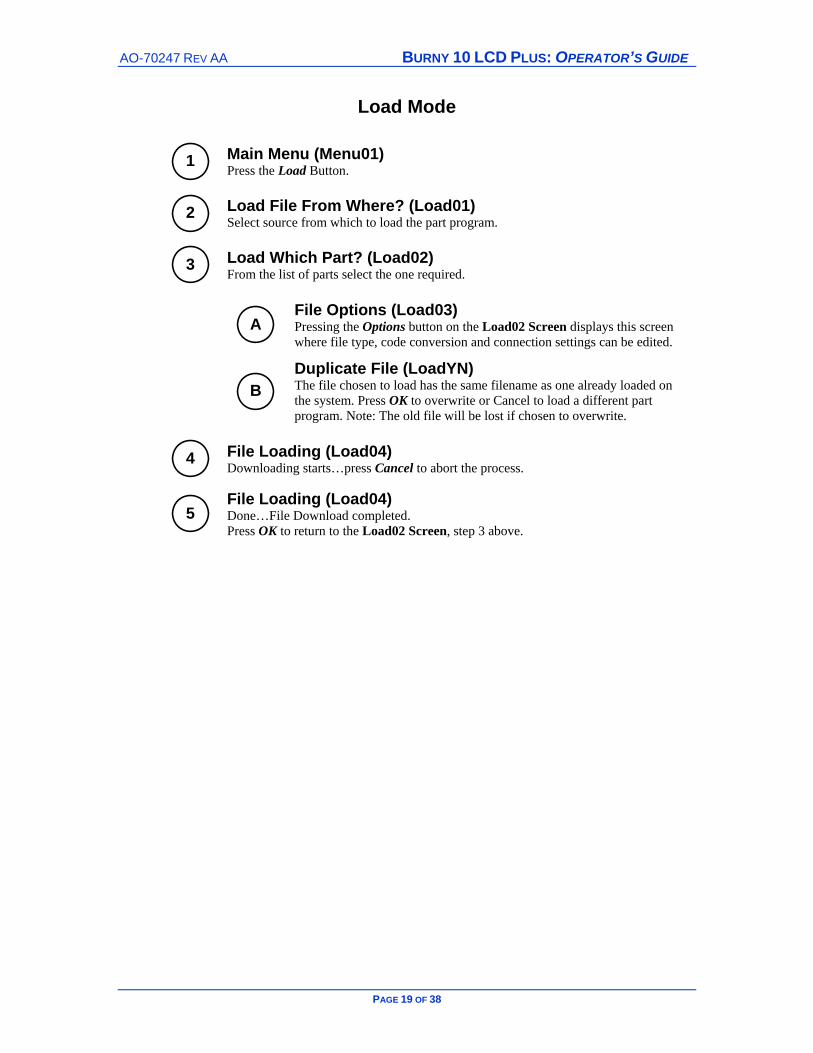
Load Mode
1
Main Menu (Menu01) Press the Load Button.
2
Load File From Where? (Load01) Select source from which to load the part program.
3
Load Which Part? (Load02) From the list of parts select the one required.
A
File Options (Load03) Pressing the Options button on the Load02 Screen displays this screen where file type, code conversion and connection settings can be edited.
B
Duplicate File (LoadYN) The file chosen to load has the same filename as one already loaded on the system. Press OK to overwrite or Cancel to load a different part program. Note: The old file will be lost if chosen to overwrite.
4
File Loading (Load04) Downloading starts…press Cancel to abort the process.
5
File Loading (Load04) Done…File Download completed. Press OK to return to the Load02 Screen, step 3 above.
BURNY 10 LCD PLUS: OPERATOR’S GUIDE AO-70247 REV AA
PAGE 20 OF 38
6.2 RUN MODE
1
2
6
5
A
3
4
Run
SelectPart
OK
GO -Part Cuts
Adjust Timer Settings AsRequired - Screen will depend
on cutting process used.
B
C
Options R/C
Timers
Row/Column Nesting

AO-70247 REV AA BURNY 10 LCD PLUS: OPERATOR’S GUIDE
PAGE 21 OF 38
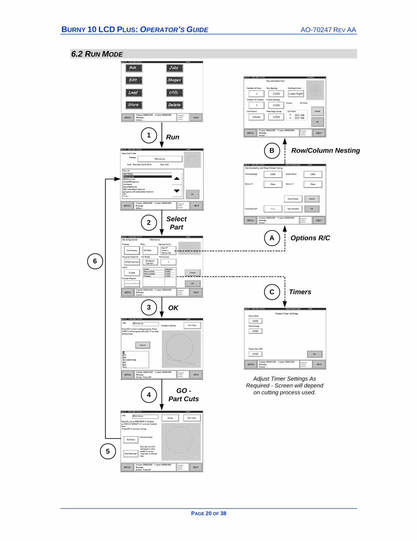
Run Mode
1
Main Menu (Menu01) Press the Run Button.
2
Select Job or Part to Run (Run01) Select the part to Run – use the scroll buttons to move through the list of parts, press on the part name to select it and then press OK. Jobs (parts previously setup, refer Section 4.1 ) are always at the top of the list and are identified by a status phrase such as “Waiting”.
3
Job Setup (Run02) On the Job Setup Screen review the settings and adjust as required. Press OK.
A
Job Geometry (Run04) To configure how a number of parts will be cut press the Options (R/C) button, where R = Rows and C = Columns.
B
Row And Column Nest (RowOptNest) Used to layout how a series of parts will be cut from the plate.
C
Timer Settings (Run05) Press the Timers button to edit. Used to enter the timer settings for the run – the actual screen displayed will depend upon the cutting process used. Edit using the toggle buttons/number keypad.
4
Run Job (Run03) To start the cutting process press the Cycle Start membrane button on the front panel. Note: on the Thumbnail Graphic Screen the cutting path will change from Red to green as the cutting progresses. Refer to Job Interrupt for information on stopping a job partway through the cut.
5
Run Job (Run03) When the job has been completed and the various timers (Bleed Off Delay, Minimum Off Time etc.) have elapsed the Job Complete/Interrupt Screen is displayed. Press Job Done.
6
Job Done Screen (Run01) Return to the Run01 Screen showing the list of current parts with the completed part displayed as “Done”. Either repeat the process to cut the next part or press the Menu button to access another mode.

BURNY 10 LCD PLUS: OPERATOR’S GUIDE AO-70247 REV AA
PAGE 22 OF 38
6.3 JOB INTERRUPT MODE
Cycle Stop
GO TO
Cycle Start
Job Interrupt
Run other part etc.
GO TO
Cycle Start
Job Interrupt - jog tool tolocation - change tool -jog back - press GO TO
Select RestartOption
Press Cycle Start
Cutting
Cutting
Cutting
1
3
42
AO-70247 REV AA BURNY 10 LCD PLUS: OPERATOR’S GUIDE
PAGE 23 OF 38
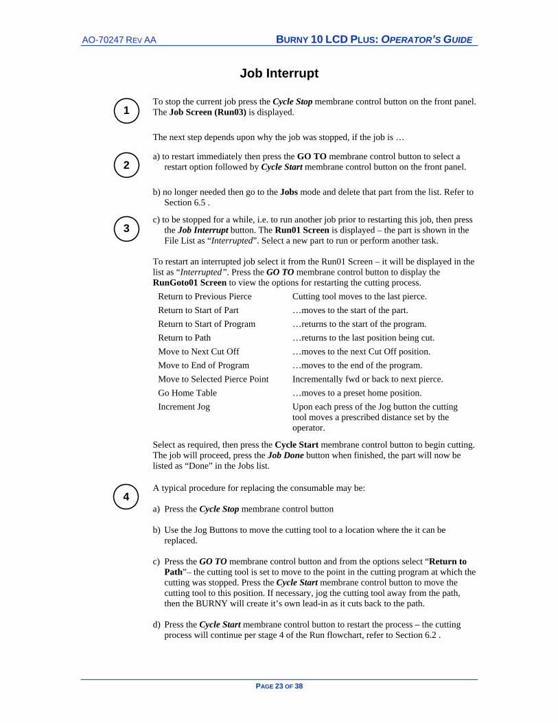
Job Interrupt
1
To stop the current job press the Cycle Stop membrane control button on the front panel. The Job Screen (Run03) is displayed.
The next step depends upon why the job was stopped, if the job is …
2
a) to restart immediately then press the GO TO membrane control button to select a restart option followed by Cycle Start membrane control button on the front panel.
b) no longer needed then go to the Jobs mode and delete that part from the list. Refer to Section 6.5 .
3
c) to be stopped for a while, i.e. to run another job prior to restarting this job, then press the Job Interrupt button. The Run01 Screen is displayed – the part is shown in the File List as “Interrupted”. Select a new part to run or perform another task.
To restart an interrupted job select it from the Run01 Screen – it will be displayed in the list as “Interrupted”. Press the GO TO membrane control button to display the RunGoto01 Screen to view the options for restarting the cutting process.
Return to Previous Pierce Cutting tool moves to the last pierce. Return to Start of Part …moves to the start of the part. Return to Start of Program …returns to the start of the program. Return to Path …returns to the last position being cut. Move to Next Cut Off …moves to the next Cut Off position. Move to End of Program …moves to the end of the program. Move to Selected Pierce Point Incrementally fwd or back to next pierce. Go Home Table …moves to a preset home position. Increment Jog Upon each press of the Jog button the cutting
tool moves a prescribed distance set by the operator.
Select as required, then press the Cycle Start membrane control button to begin cutting. The job will proceed, press the Job Done button when finished, the part will now be listed as “Done” in the Jobs list.
4
A typical procedure for replacing the consumable may be: a) Press the Cycle Stop membrane control button b) Use the Jog Buttons to move the cutting tool to a location where the it can be
replaced. c) Press the GO TO membrane control button and from the options select “Return to
Path”– the cutting tool is set to move to the point in the cutting program at which the cutting was stopped. Press the Cycle Start membrane control button to move the cutting tool to this position. If necessary, jog the cutting tool away from the path, then the BURNY will create it’s own lead-in as it cuts back to the path.
d) Press the Cycle Start membrane control button to restart the process – the cutting
process will continue per stage 4 of the Run flowchart, refer to Section 6.2 .
BURNY 10 LCD PLUS: OPERATOR’S GUIDE AO-70247 REV AA
PAGE 24 OF 38
6.4 SHAPES MODE
1
2
B
C
4
5
3
6
A
Cancel
Shapes
Back 1 Prompt
Edit
OKNew
Name
#2 Circle
OK (Next)
OK (Next)
OK (Next)
Enter Parameter/Dimension Values such as
kerf, start position etc.Number of questions, 1thru x, depends on part.
OK

AO-70247 REV AA BURNY 10 LCD PLUS: OPERATOR’S GUIDE
PAGE 25 OF 38
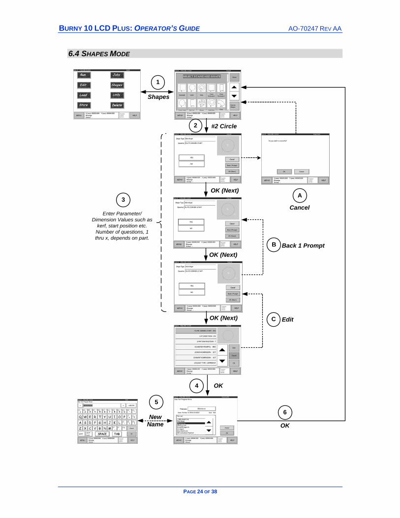
Shapes Mode
1
Main Menu (Menu01) Press the Shapes button.
2
Standard Shapes (Shapes 01) These are a number of shapes pre-configured by BURNY. Use the scroll bars to view the range of shapes. To return to the top of the list press the Home button. To make a circle – select Shape #2, Circle by pressing on either the shape or the image name.
3
Edit Shape Dimensions (Shapes02) Enter the information required to define the part, with the number of questions depending on the part. A prompt appears for each parameter/dimension to enter a value or keep the default settings using the keypad. Enter the values, press OK to enter the value and move to the next dimension.
A
Cancel (ShapesYesNo) Cancel All Dimensions, press Yes to confirm. All the dimension changes will be deleted and returns to the Standard Shapes Screen (Shapes01).
B
Back 1 Prompt Takes you to the previously entered dimension/parameter to allow for editing.
4
Summary Screen (Shapes06) Review the dimensions – scroll through the list, if a value is incorrect select it and press Edit. Press OK when edits have been confirmed.
C
Edit (Shapes06) If a dimension/parameter is incorrect press the Edit button. The Shapes02 Screen is displayed where the correct value can be entered.
5
Save File As (ShapesSaveFile) Enter filename or use the default filename. Use keyboard to enter value.
6
Standard Shapes (Shapes01) After the part file is saved press OK to return to the Standard Shapes Screen…press the Menu button to return to the Main Menu.
BURNY 10 LCD PLUS: OPERATOR’S GUIDE AO-70247 REV AA
PAGE 26 OF 38
6.5 JOBS MODE
4
Timersand Nesting
A
1
B
Jobs
Delete Job
Error -Active Job
2
3
Add Job
OK
OK

AO-70247 REV AA BURNY 10 LCD PLUS: OPERATOR’S GUIDE
PAGE 27 OF 38
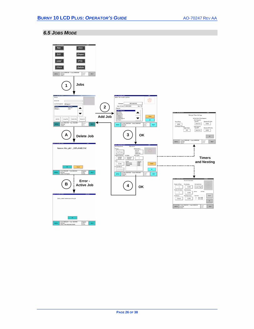
Jobs Mode
1
Main Menu (Main01) Press the Jobs button.
2
Job List (Job01) Displays the current list of jobs with their status – Done, Interrupted, Power loss, Paused, Waiting. Press Add Job to add another job to the list.
3
Select Job (Job02) From the file list select the Job/Part Program to Add. Press OK.
4
Job Setup Screen (Job04) Confirm or Edit settings. To configure the number of parts in the job press the Options (R/C) button to display the Job05 Screen. To configure the Timer settings press the Timers button to display the Job06 Screen. Press OK.
A
Delete Job (Job03) To delete a job, highlight it in the list using the scroll bars if necessary, press the Delete button on the Job List Screen (Job01).
B
Error – Active Job (JobActiveOk) The job being deleted is currently being run – wait for it to complete.
BURNY 10 LCD PLUS: OPERATOR’S GUIDE AO-70247 REV AA
PAGE 28 OF 38
6.6 EDIT MODE
1
2
3
B
A
4
Edit
Select Part
Edit the Part
Save
Options
Overwrite File?
AO-70247 REV AA BURNY 10 LCD PLUS: OPERATOR’S GUIDE
PAGE 29 OF 38
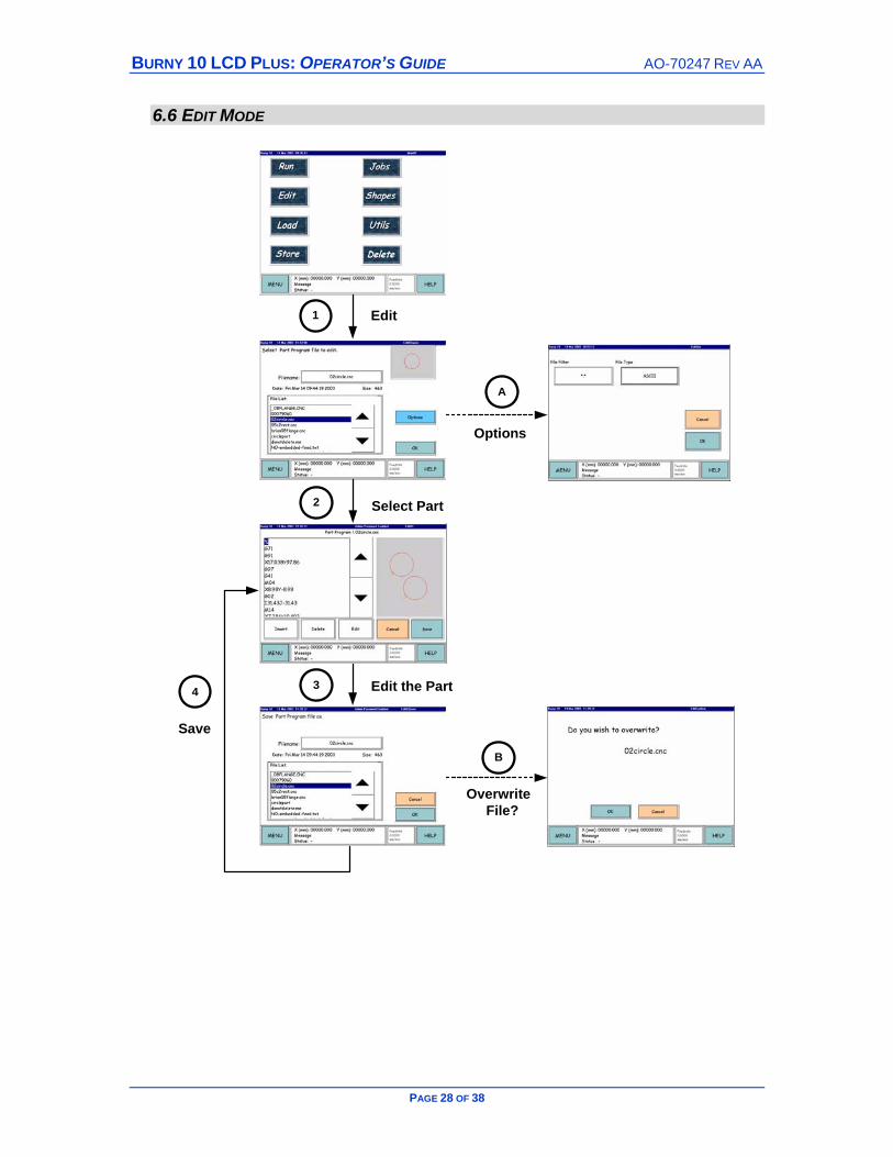
Edit Mode
1
Main Menu (Main01) Press the Edit button.
2
Select Part (Edit02Open) From the part list select the part required, use scroll bars if necessary.
A
Choose Options (EditOpt) Use the File Filter button to search for the file and the File Type to select the program language.
3
Edit Part Program (Edit01) View/Edit the part program as reqd.
Insert – new command line below the current selected Delete – delete the currently selected command line Edit – use the keyboard to edit the command.
The associated part of the thumbnail graphic will be shown in white.
4
Save The Edited Part (Edit03Save) If the part name chosen is the same as the original then confirm the part to be overwritten – note when the OK button is pressed the original will be lost. Return to the Edit Part Program Screen (Edit01). Either continue editing the part, press Cancel to return to the Select Part Screen (Edit02Open) to edit another part or press Menu to switch modes.
B
Overwrite File? (EditConfirm) The filename chosen already exists…to overwrite that file press OK or Cancel to save under a new filename?
BURNY 10 LCD PLUS: OPERATOR’S GUIDE AO-70247 REV AA
PAGE 30 OF 38
6.7 DELETE MODE
1
2
3
A
4
Delete
Select Location
Select File
OK
File inJoblist

AO-70247 REV AA BURNY 10 LCD PLUS: OPERATOR’S GUIDE
PAGE 31 OF 38
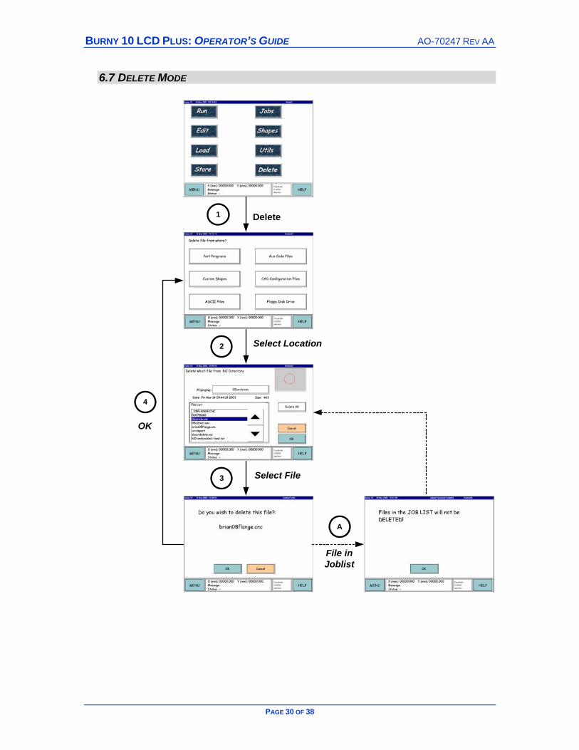
Delete Mode
The process essentially comprises of choosing the type or location of the file to be deleted and then selecting that individual file to delete.
1
Main Menu (Main01) Press the Delete button.
2
Delete From Where? (Delete01) Select either Part Programs, Custom Shapes, ASCII Files, Aux Code Files, CAD Configuration Files, Floppy Disk Drive.
3
Delete which file? (Delete02) Select the file to delete from the list, use the scroll buttons to move through the list to highlight that file. Press OK.
4
Confirm Deletion (DeleteYesNo) Press the OK button to confirm.
A
File in Joblist (DeleteOK) The “Files in the Job List will not be Deleted!”: message indicates that the file being deleted is in the Job List, refer to Section 6.5 to remove the file from the JobList.

BURNY 10 LCD PLUS: OPERATOR’S GUIDE AO-70247 REV AA
PAGE 32 OF 38
6.8 STORE MODE
1
2
3
4
A
B
Options
Store
Store Device
Store Which File
Error
DownloadComplete

AO-70247 REV AA BURNY 10 LCD PLUS: OPERATOR’S GUIDE
PAGE 33 OF 38
Store Mode
1
Main Menu (Menu01) Press the Store Button.
2
Store File to Where? (Store01) Select where you want to save the part file.
3
Store Which Part? (Store02) From the list of parts select the one required. Press OK to proceed.
A
File Options (Store03) Select File type etc.
4
Storing File (Store04) Downloading starts and on completion return to the Store02 Screen. Either store another part, press Cancel to return to the Store01 Screen to select another storage device or press Menu to switch modes.
B
Error During Save (StoreYN) An error has occurred during the save process, press OK and review the saving process.
BURNY 10 LCD PLUS: OPERATOR’S GUIDE AO-70247 REV AA
PAGE 34 OF 38
6.9 UTILITIES MODE
1
S
T
L
2
H2
H1
Utils
SystemSetup
TouchScreen
Language
Set Homes
Homing
Shutdown
AO-70247 REV AA BURNY 10 LCD PLUS: OPERATOR’S GUIDE
PAGE 35 OF 38
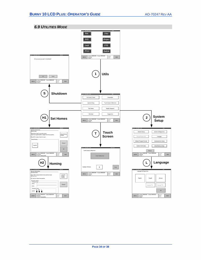
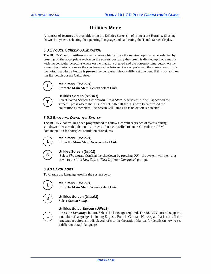
Utilities Mode
A number of features are available from the Utilities Screens – of interest are Homing, Shutting Down the system, selecting the operating Language and calibrating the Touch Screen display.
6.9.1 TOUCH SCREEN CALIBRATION The BURNY control utilizes a touch screen which allows the required options to be selected by pressing on the appropriate region on the screen. Basically the screen is divided up into a matrix with the computer detecting where on the matrix is pressed and the corresponding button on the screen. For various reasons the synchronization between the computer and the screen may drift to the point that when a button is pressed the computer thinks a different one was. If this occurs then run the Touch Screen Calibration.
1
Main Menu (Main01) From the Main Menu Screen select Utils.
T
Utilities Screen (Utils01) Select Touch Screen Calibration. Press Start. A series of X’s will appear on the screen…press where the X is located. After all the X’s have been pressed the calibration is complete. The screen will Time Out if no action is detected.
6.9.2 SHUTTING DOWN THE SYSTEM The BURNY control has been programmed to follow a certain sequence of events during shutdown to ensure that the unit is turned off in a controlled manner. Consult the OEM documentation for complete shutdown procedures.
1
Main Menu (Main01) From the Main Menu Screen select Utils.
S
Utilties Screen (Util01) Select Shutdown. Confirm the shutdown by pressing OK – the system will then shut down to the “It’s Now Safe to Turn Off Your Computer” prompt.
6.9.3 LANGUAGES To change the language used in the system go to:
1
Main Menu (Main01) From the Main Menu Screen select Utils.
2
Utilities Screen (Utils01) Select System Setup.
L
Utilities Setup Screen (Utils13) Press the Language button. Select the language required. The BURNY control supports a number of languages including English, French, German, Norwegian, Italian etc. If the language required isn’t displayed refer to the Operation Manual for details on how to set a different default language.
BURNY 10 LCD PLUS: OPERATOR’S GUIDE AO-70247 REV AA
PAGE 36 OF 38
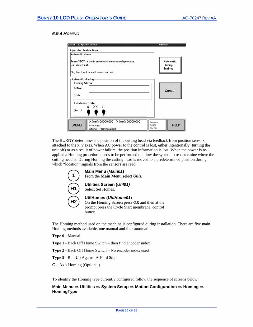
6.9.4 HOMING
The BURNY determines the position of the cutting head via feedback from position sensors attached to the x, y axes. When AC power to the control is lost, either intentionally (turning the unit off) or as a result of power failure, the position information is lost. When the power is re-applied a Homing procedure needs to be performed to allow the system to re-determine where the cutting head is. During Homing the cutting head is moved to a predetermined position during which “location” signals from the sensors are read.
1
Main Menu (Main01) From the Main Menu select Utils.
H1
Utilities Screen (Util01) Select Set Homes.
H2
UtilHomes (UtilHome01) On the Homing Screen press OK and then at the prompt press the Cycle Start membrane control button.
The Homing method used on the machine is configured during installation. There are five main Homing methods available, one manual and four automatic:
Type 0 - Manual
Type 1 - Back Off Home Switch – then find encoder index
Type 2 - Back Off Home Switch – No encoder index used
Type 5 - Run Up Against A Hard Stop
C – Axis Homing (Optional)
To identify the Homing type currently configured follow the sequence of screens below:
Main Menu ⇒ Utilities ⇒ System Setup ⇒ Motion Configuration ⇒ Homing ⇒ HomingType
AO-70247 REV AA BURNY 10 LCD PLUS: OPERATOR’S GUIDE
PAGE 37 OF 38
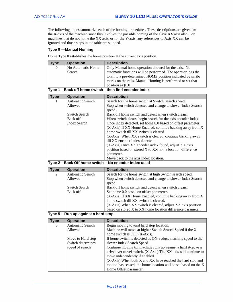
The following tables summarize each of the homing procedures. These descriptions are given for the X-axis of the machine since this involves the possible homing of the slave XX axis also. For machines that do not home the XX axis, or for the Y-axis, any references to Axis XX can be ignored and those steps in the table are skipped.
Type 0 —Manual Homing Home Type 0 establishes the home position at the current axis position.
Type Operation Description 0 No Automatic Home
Search Only Manual home operation allowed for the axis. No automatic functions will be performed. The operator jogs the torch to a pre-determined HOME position indicated by scribe marks on the rails. Manual Homing is performed to set that position as (0,0).
Type 1—Back off home switch --then find encoder index
Type Operation Description 1 Automatic Search
Allowed Switch Search Back off Index Search
Search for the home switch at Switch Search speed. Stop when switch detected and change to slower Index Search speed. Back off home switch and detect when switch clears. When switch clears, begin search for the axis encoder Index. Once index detected, set home 0,0 based on offset parameter. (X-Axis) If XX Home Enabled, continue backing away from X home switch till XX switch is cleared. (X-Axis) When XX switch is cleared, continue backing away till XX encoder index detected. (X-Axis) Once XX encoder index found, adjust XX axis position based on stored X to XX home location difference parameter. Move back to the axis index location.
Type 2—Back Off home switch – No encoder index used
Type Operation Description 2 Automatic Search
Allowed Switch Search Back off
Search for the home switch at high Switch search speed. Stop when switch detected and change to slower Index Search speed. Back off home switch and detect when switch clears. Set home 0,0 based on offset parameter. (X-Axis) If XX Home Enabled, continue backing away from X home switch till XX switch is cleared. (X-Axis) When XX switch is cleared, adjust XX axis position based on stored X to XX home location difference parameter.
Type 5 – Run up against a hard stop
Type Operation Description 5 Automatic Search
Allowed Move to Hard stop Switch determines speed of search
Begin moving toward hard stop location. Machine will move at higher Switch Search Speed if the X home switch is OFF (X-Axis). If home switch is detected as ON, reduce machine speed to the slower Index Search Speed Continue moving till machine runs up against a hard stop, or a drive over travel switch. (X-Axis) The XX axis will continue to move independently if enabled. (X-Axis) When both X and XX have reached the hard stop and motion has ceased, the home location will be set based on the X Home Offset parameter.

BURNY 10 LCD PLUS: OPERATOR’S GUIDE AO-70247 REV AA
PAGE 38 OF 38
BLANK