Bulletin of the JSME Journal of Advanced Mechanical Design ...
12
Bulletin of the JSME Journal of Advanced Mechanical Design, Systems, and Manufacturing Vol.10, No.1, 2016 Paper No.15-00498 © 2016 The Japan Society of Mechanical Engineers [DOI: 10.1299/jamdsm.2016jamdsm0015] Abstract In order to solve the time-varying bending bearing capacity of orthogonal curve-face gear, we proposed the calculation and test method of bending stress of gear tooth root. Using the spatial engagement theory and gear carrying capacity theory, the parametric equations of pitch curve and pressure angle on the pitch curve of orthogonal curve-face gear were derived, and the algorithm of equivalent tooth form factor and equivalent stress correction factor was obtained. Force condition in the meshing process of orthogonal curve-face gear was analyzed. The variation of principal curvature and force of orthogonal curve-face gear was achieved. Using the simplification algorithm of regarding the orthogonal curve-face gear pair as equivalent non-circular gear rack, the calculation method of bending stress of orthogonal curve-face gear was acquired, and the impact of basic structure parameter of gear pair on bending stress was analyzed. Using five-axis CNC machining to process the entity. Experimental of orthogonal curve-face gear using strain gauges was carried out to justify the correction of the theory. Comparing the theoretical calculation and experimental results, the variation laws was similar, and then the calculation method of bending strength of orthogonal curve-face gear was verified. Key words : Face gear, Time-varying ratio, Non-circle rack, Bending stress, Strain gauge 1. Introduction Orthogonal curve-face gear transmission is a new type of gear transmission that orthogonal curve-face gear meshing with non-circular gear (Lin, et al., 2013). This kind of transmission combines the characteristics non-circular gear, non-circular bevel gear and face gear, it can transmit time-varying transmission ratio motion between intersecting axis. The orthogonal curve-face gear can be manufactured with available machine tools, and it can be mass-produced, so its application prospects are very broad. In this paper, ORC gear is stand for the orthogonal curve-face gear. (Lin, et al., 2013) first proposed the design of orthogonal variable transmission ratio face gear pair, and derived the analytical expression of tooth surface equation of curve-face gear. Litvin et al. (2002) used the method of finite element static loading, studied the bending stress of face gears processed by sharp shaper cutters and fillet shaper cutters respectively. And he used the instances proved that the bending stress of face gear processed by fillet shaper cutters reduced about 10%. In the FACET project, M.Guingand et al. (2005) used the FEA method to calculate the bending stress of tooth root of face gear at different meshing locations. And he tested the bending stress of corresponding points in experiments to verify the calculated results. (Wang, et al., 2012) and (Chang, et al,. 2000) carried out the load tooth contact analysis and tooth contact analysis to orthogonal face-gear drive respectively. Ulrich Kissling et al. (2007) calculated the bending strength of face gear and the corresponding load factor and safety factor using ISO 6336 and ISO 10300 standard. (Lin, et al., 2013) and (Lin, et al., 2013) proposed the method of equivalent the eccentric-high order elliptical bevel gear pair and elliptical bevel gear as bevel gear respectively, and the calculation method of bending strength of the corresponding gear pair was derived. Patil et al. (2014) analyzed the force condition, theoretical calculations and finite element analysis of bevel gear. (Lu, et al., 1995) analyzed the load distribution on tooth surface of double circular-arc helical gears, and the root stress of the gear pair was obtained by FEA method. Experimental measurement methods of bending stress of various types of gear includes photoelastic experiment (Sekar, et al., 2014, Pandya, et al., 2013), strain gauge method (Brandão, et al., 2014, Verlak, et al., 2014), FZG gear test Bending stress analysis of orthogonal curve-face gear * The State Key Laboratory of Mechanical Transmission, Chongqing University ** Taiyuan University of Science and Technology Taiyuan 030024, China E-mail: [email protected] Received 8 September 2015 1 Yao WANG* , **, Chao LIN*, Zhiqin CAI* and Chao HUANG* Chongqing 400044, China
Transcript of Bulletin of the JSME Journal of Advanced Mechanical Design ...

Bulletin of the JSME
Journal of Advanced Mechanical Design, Systems, and ManufacturingVol.10, No.1, 2016
Paper No.15-00498© 2016 The Japan Society of Mechanical Engineers[DOI: 10.1299/jamdsm.2016jamdsm0015]
0123456789
Abstract
In order to solve the time-varying bending bearing capacity of orthogonal curve-face gear, we proposed the
calculation and test method of bending stress of gear tooth root. Using the spatial engagement theory and gear
carrying capacity theory, the parametric equations of pitch curve and pressure angle on the pitch curve of
orthogonal curve-face gear were derived, and the algorithm of equivalent tooth form factor and equivalent stress
correction factor was obtained. Force condition in the meshing process of orthogonal curve-face gear was
analyzed. The variation of principal curvature and force of orthogonal curve-face gear was achieved. Using the
simplification algorithm of regarding the orthogonal curve-face gear pair as equivalent non-circular gear rack,
the calculation method of bending stress of orthogonal curve-face gear was acquired, and the impact of basic
structure parameter of gear pair on bending stress was analyzed. Using five-axis CNC machining to process the
entity. Experimental of orthogonal curve-face gear using strain gauges was carried out to justify the correction of
the theory. Comparing the theoretical calculation and experimental results, the variation laws was similar, and
then the calculation method of bending strength of orthogonal curve-face gear was verified.
Key words : Face gear, Time-varying ratio, Non-circle rack, Bending stress, Strain gauge
1. Introduction
Orthogonal curve-face gear transmission is a new type of gear transmission that orthogonal curve-face gear
meshing with non-circular gear (Lin, et al., 2013). This kind of transmission combines the characteristics non-circular
gear, non-circular bevel gear and face gear, it can transmit time-varying transmission ratio motion between intersecting
axis. The orthogonal curve-face gear can be manufactured with available machine tools, and it can be mass-produced,
so its application prospects are very broad. In this paper, ORC gear is stand for the orthogonal curve-face gear.
(Lin, et al., 2013) first proposed the design of orthogonal variable transmission ratio face gear pair, and derived
the analytical expression of tooth surface equation of curve-face gear. Litvin et al. (2002) used the method of finite
element static loading, studied the bending stress of face gears processed by sharp shaper cutters and fillet shaper
cutters respectively. And he used the instances proved that the bending stress of face gear processed by fillet shaper
cutters reduced about 10%. In the FACET project, M.Guingand et al. (2005) used the FEA method to calculate the
bending stress of tooth root of face gear at different meshing locations. And he tested the bending stress of
corresponding points in experiments to verify the calculated results. (Wang, et al., 2012) and (Chang, et al,. 2000)
carried out the load tooth contact analysis and tooth contact analysis to orthogonal face-gear drive respectively. Ulrich
Kissling et al. (2007) calculated the bending strength of face gear and the corresponding load factor and safety factor
using ISO 6336 and ISO 10300 standard. (Lin, et al., 2013) and (Lin, et al., 2013) proposed the method of equivalent
the eccentric-high order elliptical bevel gear pair and elliptical bevel gear as bevel gear respectively, and the calculation
method of bending strength of the corresponding gear pair was derived. Patil et al. (2014) analyzed the force condition,
theoretical calculations and finite element analysis of bevel gear. (Lu, et al., 1995) analyzed the load distribution on
tooth surface of double circular-arc helical gears, and the root stress of the gear pair was obtained by FEA method.
Experimental measurement methods of bending stress of various types of gear includes photoelastic experiment (Sekar,
et al., 2014, Pandya, et al., 2013), strain gauge method (Brandão, et al., 2014, Verlak, et al., 2014), FZG gear test
Bending stress analysis of orthogonal curve-face gear
* The State Key Laboratory of Mechanical Transmission, Chongqing University
** Taiyuan University of Science and Technology
Taiyuan 030024, China
E-mail: [email protected]
Received 8 September 2015
1
Yao WANG*,**, Chao LIN*, Zhiqin CAI* and Chao HUANG*
Chongqing 400044, China

2
Wang, Lin, Cai and Huang, Journal of Advanced Mechanical Design, Systems, and Manufacturing, Vol.10, No.1 (2016)
© 2016 The Japan Society of Mechanical Engineers[DOI: 10.1299/jamdsm.2016jamdsm0015]2
(Miyachika, et al., 2014).
Tooth root bending strength is one of the most important strength properties of ORC gear. In engineering
application, tooth root bending strength of ORC gear directly effects the life and safety of the gear pair. Many
researches on bending stresses of different gears have been published by a lot of authors in the past, however, studies
on ORC gear are rarely published. It greatly limits the development of the gear pair. In this paper, the bending strength
of the ORC gear was studied, and the calculation method of bending stress was derived. Bending stresses of tooth root
in the meshing process were measured by means of the strain gauge method. The changes of the bending stresses in
meshing process were obtained. The maximum bending stress were determined which is similar to the result of theory
proposed in this paper.
2. Drive principle of ORC gear pair
In the meshing process of ORC gear pair, the transmission is embodied in two gear pitch curves for pure rolling.
These two section curves are the foundation of designing gear drive, and the ORC gear transmission model is
established in Fig. 1.
'(O )f fO
'(O )d dO
'(X )d dX
'(Y )d dY
'(X
)f
fX
'(Y )f fY
'(Z )f fZ
'(Z )d dZ
fQ
dQ
0r R
2
1
Pitch curve of
non-circle gear
Pitch curve of
ORC gear
Fig.1 Spatial engagement of ORC gear
According to spatial engagement theory (Litvin, F. L. and Fuentes, A., 2004), the non-circle gear’s fixed coordinate
system ( )f f ff X Y Z , ORC gear’s fixed coordinates ( )d d dd X Y Z , dynamic coordinate system of non-circle
gear' ' ''( )f f ff X Y Z , and ORC gear’s dynamic coordinate system
' ' ''( )d d dd X Y Z are established on reference (Lin, et al.,
2013). The dynamic coordinate system and fixed coordinate system are the same in the initial state. In the process of
transmission, the non-circle gear rotates clockwise around the axis f fO Z , and the angular velocity is 1 .The ORC gear
rotates clockwise around the axisd dO Z ,and the angular velocity is 2 .The distance between plane
d d dY O Z and plane
f f fX O Y is R, between plane f f fO Y Z and plane d d dO X Y is 0r .
In the process of gear transmission, the pitch curves of ORC gear pair do the pure rolling. Set fQ as a point on
pitch curve of the non-circle gear , and dQ as a point on ORC gear. When the non-circle gear rotates the angle
1 , and
the ORC gear rotates the angle 2 ,
fQ anddQ are overlapped. According to the principle of gear engagement, in the
process of gear transmission,'ffM is the homogeneous transformation matrix from the non-circle gear’s dynamic
coordinate 'f to the static coordinate system f ,and dfM is the homogeneous transformation matrix from the non-circle
gear’s static coordinate system f to the ORC gear’s static coordinate system d , and 'd dM is the homogeneous
transformation matrix from the ORC gear’s static coordinate system d to dynamic coordinate 'd . The
Homogeneous transformation matrix from the non-circle gears dynamic coordinate 'f to the ORC gear’s dynamic
coordinate 'd is:
1 2 1 2 2 2
2 1 1 2 2 2
' ' ' '
1 1 0
sin sin cos sin cos cos
cos sin cos sin sin sin
cos sin 0
0 0 0 1
d f d d df ff
R
RM M M M
r
(1)
fQ can be expressed as
1 1 1 1[ ( )cos ( )sin 0 1]T
fQ r r on the coordinate 'f .According to the relationship
of coordinate transformation, dQ on the coordinate 'd can be expressed as:

2
Wang, Lin, Cai and Huang, Journal of Advanced Mechanical Design, Systems, and Manufacturing, Vol.10, No.1 (2016)
© 2016 The Japan Society of Mechanical Engineers[DOI: 10.1299/jamdsm.2016jamdsm0015]3
1 1
1 1
' 2
' 2
' '
' 0 1
cos
sin
0 ( )
1 1
( )cos
( )sin
1
qd
qd
d f
qd
x R
y RM
z r
r
r
r
(2)
Where, 1( )r is the polar equation of non-circle gear pitch curve.
So the parameter equations of pitch curve of ORC gear are:
1
1
10
10
1 0 1
1( ) cos[ ( )d ]
1( ) sin[ ( )d ]
( ) ( )
d
d
d
x R rR
y R rR
z r r
(3)
3. Force analysis of ORC gear pair
Whether the gear pair could function properly or whether it could reach the life expectancy were determined by the
stress status of gear tooth. It is significant to analyze the force situation of ORC gear from the point of strength
checking and the designing of gear pair.
The motion law of ORC gear pair is known. The torque relationship of the gear pair and the stress situation of the
meshing point can be obtained when the non-circle gear rotates at a constant speed. Assume that normal force nF
concentrate on the normal section of tooth profile on pitch curve during the meshing. The normal force can be divided
into two perpendicular forces: peripheral force tF and axial force
aF , as shown in Fig. 2.
nF
tF
aF
2ω
1ω1T
2T·
dX
dY
dZ
dO
2h
1r
2r3r1h
12345 d
nF
tF
aF
n
nNon-circle gear
ORC gear
Pitch curve
Fig.2 force analysis of the gear pair
As is shown in Fig. 2, 1T and
1 are the driving torque on the axis of non-circle gear and the angular velocity of
non-circle gear, respectively. 2T and
2 are the effective load torque on the axis of ORC gear and the angular
velocity of ORC gear, respectively. The ORC gear pair transmits the variable ratio movement. So there must be an
angular acceleration in meshing process. The relationship of driving torque and load torque is:
2 1 1
1 1
12 1
( ) ( )( )
( )
d dT JT
i
(4)
Where, 1( )dJ and 1( )d are shown in Eq. (5) and Eq. (6), respectively. 12 1( )i is transmission ratio of ORC gear
pair. Consider only the moment of inertia of ORC gear during the meshing. The moment of inertia of ORC gear is:
2
Wang, Lin, Cai and Huang, Journal of Advanced Mechanical Design, Systems, and Manufacturing, Vol.10, No.1 (2016)
© 2016 The Japan Society of Mechanical Engineers[DOI: 10.1299/jamdsm.2016jamdsm0015]4
4 4 4 4
1 2 1 2 1 1 2 3( ) {( )[ ] ( )}2
dJ r r h h h r r
(5)
Where, is the density of ORC gear.1r ,
2r ,3r ,
1h and2h are geometric dimension of gear shown in Fig. 2.
The angular acceleration of ORC gear 1( )d is:
2
1 12 1
1 2
112 1
( )( )
( )d
di
di
(6)
Convert the driving torque of non-circle gear to the middle point of gear tooth. The force components of ORC gear
can be obtained as:
2' 31
2 12 12
12 1
t 1
t 1
n 1
1
r 1 t 1 1
( )( )
( )
( )( )
cos ( )
( ) ( ) tan ( )
d
d
T i r drd dzi
FR
FF
F F
(7)
Where,1( )d is the pressure angle of ORC gear pair.
4. The calculation of main parameters for tooth strength
4.1 Calculation of pressure angle
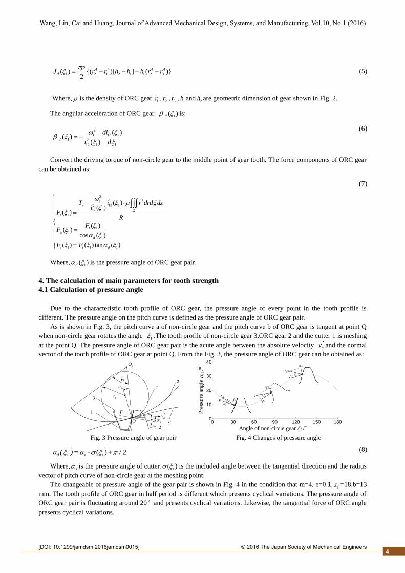
Due to the characteristic tooth profile of ORC gear, the pressure angle of every point in the tooth profile is
different. The pressure angle on the pitch curve is defined as the pressure angle of ORC gear pair.
As is shown in Fig. 3, the pitch curve a of non-circle gear and the pitch curve b of ORC gear is tangent at point Q
when non-circle gear rotates the angle 1 .The tooth profile of non-circle gear 3,ORC gear 2 and the cutter 1 is meshing
at the point Q. The pressure angle of ORC gear pair is the acute angle between the absolute velocity qv and the normal
vector of the tooth profile of ORC gear at point Q. From the Fig. 3, the pressure angle of ORC gear can be obtained as:
sO
1
sr
2u
qs
qv1
3
c
a
b
2
Q
F
0 30 60 90 120 150 180
0
10
20
30
40
Angle of non-circle gear 1/°
Pre
ssu
re a
ng
le
d /
°
Fn
FnFn
Ft
FtFt
Fa
Fa
Fa
αd
αd
αd
Fig. 3 Pressure angle of gear pair Fig. 4 Changes of pressure angle
1 1( ) / 2d sα ( )= α - + (8)
Where,s is the pressure angle of cutter. 1( ) is the included angle between the tangential direction and the radius
vector of pitch curve of non-circle gear at the meshing point.
The changeable of pressure angle of the gear pair is shown in Fig. 4 in the condition that m=4, e=0.1,sz =18,b=13
mm. The tooth profile of ORC gear in half period is different which presents cyclical variations. The pressure angle of
ORC gear pair is fluctuating around 20°and presents cyclical variations. Likewise, the tangential force of ORC angle
presents cyclical variations.

2
Wang, Lin, Cai and Huang, Journal of Advanced Mechanical Design, Systems, and Manufacturing, Vol.10, No.1 (2016)
© 2016 The Japan Society of Mechanical Engineers[DOI: 10.1299/jamdsm.2016jamdsm0015]
4.2 Calculation of Principal Curvature
Principal curvatures of tooth profile directly impact on the shape of contact region and the contact stress on the
tooth surface. Due to the time-varying characteristic of the tooth surface of ORC gear, analyze of the principal
curvatures of ORC gear is significant to study of tooth form. Based on the differential geometry, the tooth surface
equation can be expressed as the vector function in literature (Lin, et al., 2013) :
1 2 2 2
2 s 1 s 2 s 2 s 1 s
2 s s 1 s
( , )
{sin [r sin( ) Asin ] cos (u R)} { cos [r sin( ) Asin ]
sin (u R)} [r(0) cos( ) Acos ]
sr = x i+ y j + z k
i
j r k
(9)
Where,sr is the radius vector of any point on the tooth profile of cutter.
s is the included angle between sr and
coordinate axis.su is the coefficient of face width which variables along the direction of tooth width of cutter’s tooth
profile. is the angle rotated around the spindle of the cutter. A is the center distance between cutter and non-circle
gear. is the included angle between the cutter center and meshing point.
Representation. The sr ,
1r ,s 1r ,
s sr and 1 1r can be derived. Here, sr represent taking the partial
derivative of r with respect tos . The rest may be deduced by the analogy.
The unit normal vector n of tooth surface of ORC gear is :
s 1
1
s 1
s
r rn( , )=
r r
(10)
In terms of the second basic homogeneous equation, the principal curvatures should meet the equation:
2 II 2 II 2(EG - F )K -(EN - 2FM +GL)K +(LN - M )= 0 (11)
Where,s
s 1
1
2
2
( r )
r r
E
(
=
r )
F
G
,1 s s
1 s 1
1 1 1
( , )
( , )
( , )
s
s
s
n rL
M n r
N n r
.
The results of Eq. (11) areII
1K and
II
2K which are the two principal curvatures of ORC gear.
II
1,2 1( , )2
2
s 2 2 2
2MF - LG - NE NE+2MF + LG LN - MK = - ( ) -
2(EG - F ) 2(EG - F ) 2(EG - F )
(12)
The changeable of tooth surface’s principal curvature in half the period of the ORC gear using matlab is shown in
Fig. 5 in the condition that m=4,e=0.1,sz =18,b=13 mm.
1.4 2 2.6 3.20
1
2
3
4
5x 10
-3
Angle of non-circle gear 1/(°)
Pri
ncip
al
cu
rvatu
re K
II
Fig. 5 The principal curvature of curve face gear
The absolute values of the two curvatures are the same. So one of the two curvatures are discussed in this paper.
The principal curvature of ORC gear, shown in Fig. 5, is small respect to that of involute gear. So the intersection of
gear tooth and its section can be approximately regarded as straight line, and the tooth surface can be approximately
regarded as plane. As can be seen from the simulation manufacturing process, the non-circle gear is rotated around a
fixed axis, and the movement of ORC gear can be approximately regarded as straight line. Hence, ORC gear pair can
be equivalent to non-circle gear rack.
5

2
Wang, Lin, Cai and Huang, Journal of Advanced Mechanical Design, Systems, and Manufacturing, Vol.10, No.1 (2016)
© 2016 The Japan Society of Mechanical Engineers[DOI: 10.1299/jamdsm.2016jamdsm0015]6
5. Analysis and calculation of bending stress
The broken of gear tooth is one of the main reasons of gear failure. To avoid early failure, the calculation of
bending fatigue strength is necessary. While the pitch curve of ORC gear is changing, analyze and calculate of the
bending strength is very complicated. This paper uses the method of equivalent to simplified the solving process of the
bending stress of ORC gear.
5.1 Equivalent principle of bending stress
Define the instantaneous equivalent gear pair of ORC gear pair as non-circle gear rack with the same module and
curvature radius of pitch. The strength of tooth is greatly influenced by the tooth profile which is mostly decided by the
curvature radius of pitch. Hence, the tooth profile of instantaneous equivalent gear pair and ORC gear pair are similar.
From the point of view of tooth strength, the pitch curve of ORC gear pair can be regarded as a continuous function.
And the meshing process of ORC gear pair can be viewed as that of a finite number of the instantaneous equivalent
gear pair. The equivalent procedure is shown in Fig. 6 below.
Same modules.
Reference radius equal to pitch
curve radius
Non-circle gear
ORC gear
Non-circle gear
Non-circle rack
Fig.6 equivalent procedure of ORC gear pair
This paper establishes the equation of bending stress of ORC gear according to the cantilever beam model.
Suppose that the maximum bending moment located on the upper bound of single tooth-meshing area, critical section is
determined by the 30° tangent method. Thus, the equation of bending stress is :
1 1 1
F 1
( ) ( ) ( )( )
m
tKF Y Y
b
Fa Sa
(13)
Where, K is the load factor. 1( )Y Fa
is the equivalence tooth form factor. 1( )Y Sa
is the equivalence stress
correction factor. b is the width of tooth of ORC gear. m is the module of gear pair.
5.2 Pitch curve of equivalence rack and equivalence factors
5.2.1 Pitch curve of equivalence rack
The pitch curve of ORC gear is located on a cylinder surface. The curve of addendum and dedendum are
equidistance curve relative to the pitch on the cylinder surface. And the curve on cylinder is difficult to solve. In order
to simplify the problems, the curves are all expanded into planar curves.
According to the theory of developable surface in geometry theory, we know: cylinder can be expanded along
every generatrix. Hence, the pitch curve, addendum curve and dedendum curve can be expanded into a plane
coordinate system, as shown in Fig. 7. The ORC gear pair between intersecting axes is expanded into a transmission of
non-circle gear rack.
1.Pitch curve of non-circle gear 2.Plane addendum curve of ORC gear
3.Plane pitch curve of ORC gear 4. Plane dedendum curve of ORC gear
Fig. 7 The plane curves of ORC gear

2
Wang, Lin, Cai and Huang, Journal of Advanced Mechanical Design, Systems, and Manufacturing, Vol.10, No.1 (2016)
© 2016 The Japan Society of Mechanical Engineers[DOI: 10.1299/jamdsm.2016jamdsm0015]
The parametric equations of the plane pitch curve is:
1
10
1 0 1
( ) ( )d
( ) r ( )
x r
y r
(14)
From the Eq. (14) and the theory of plane geometry, the parametric equation of the plane addendum curve and the
plane dedendum curve are obtained as:
1
10
1 0 1
( ) ( )d sin
( ) r ( ) cos
a a
a a
x r h
y r h
(15)
1
10
1 0 1
( ) ( )d sin
( ) r ( ) cos
f f
f f
x r h
y r h
(16)
Where, 1 1 1 1 1arctan[ sin( )] / [1 cos( )]en n e n ; *
ah mh , *
ah is addendum coefficient; * *( )f ah m h c , *c is
bottom clearance coefficient.
From the differential geometry, the equations of equivalent reference radius of ORC gear can be calculated as:
2 '2 2 3/2
2 1
1 '' '
2 1 2 1
[ ' ( )]( )
'( ) ''( )dv
R rr
R r r
(17)
From the Eq. (15), equation of equivalent radius of addendum of ORC gear can be calculated:
2 2 ' 2 3/2
1 2
1 '' 2 ' 2
1 2 2 1
[r' ( ) R '(2(asin cos ) h ')]( )=
(r'( ) h 'sin( ))(R ''cos( ) ' sin( )) ( 'cos( ))( ''( ) ''sin( ) ' cos( ))
a a
av
a a a a a a
h cr
h h R h r h h
(18)
From the Eq. (16), equation of equivalent radius of dedendum of ORC gear can be calculated:
' 2 2 3/2
2 1
1 ' 2 '' 2
2 1 1 2
[( 'cos( )) (h 'sin( ) r'( )) ]( )=
( 'cos( ))( ''sin( ) ' cos( ) ''( )) (h 'sin( ) r'( ))(R ''cos( ) ' sin( ))
f f
fv
f f f f f f
R hr
R h h h r h h
(19)
5.2.2 Instantaneous equivalent factors
Considered the influence of tooth form on the nominal bending stress while loading on the addendum, the tooth
form factor YFa is introduced. The factor which transforms the nominal bending stress to root stress is the stress
correction factor YSa
. It combines the effect of stress concentration of transmission curve and other stress except
bending stress. Based on the machinery’s handbook (Green, R. E. 1992), the equivalent tooth form factor 1( )FaY and
the equivalent stress correction factor 1( )Y
Saof ORC gear can be obtained as the Eq. (20) and (21).
2 2
1 2
6 [4sec ( ) mtan 2 (2sec 3)]( )
[ 4 tan (h ) 2 (1/ cos 3)]
d av fv d s d
Fa
d fv s s d
m r rY
m
(20)
Where,s is the fillet radius of cutter.
2 2
1 2 2
1(1.21 2.3[4sec ( ) mtan 2 (sec 3)] 2[ 4 tan (h ) 4 (sec 3)
4 tan (h ) 4 (sec 3) 4 tan (h )( ) (1.2 0.26 ) [
44sec ( ) mtan 2 (sec 3)
13]
cos
d av fv d s d d fv s s d
d fv s s d d fv s
sd av fv d s d
r r m
d
m mY
r r
Sa
)]
(21)
7

2
Wang, Lin, Cai and Huang, Journal of Advanced Mechanical Design, Systems, and Manufacturing, Vol.10, No.1 (2016)
© 2016 The Japan Society of Mechanical Engineers[DOI: 10.1299/jamdsm.2016jamdsm0015]
0 60 120 180 240 300 3601.5
2
2.5
3
3.5
To
oth
fo
rm f
acto
r Y
Fa
Angle of non-circle gear1/(°)
0 60 120 180 240 300 3603
3.5
4
4.5
5
5.5
Str
ess
corr
ecti
on
fac
tor
YS
a
YFa
YSa
Fig.8 Changes of factors
The variation of tooth form factor and stress correction factor of ORC gear are shown in Fig. 8 assuming that m=4,
e=0.1,sz =18. Figure 8 shows that the two factors are symmetric around the axis
1 180 and varying periodically.
5.3 Change law of bending stress of ORC gear
With insufficient bending fatigue strength of gear tooth, the gear pair is easy to be broken like tooth fracture, plastic
deformation, etc. Therefore, analyze the impact of basic parameters of ORC gear pair on the bending stress is of great
significant. The basic parameters are shown in Tab. 1. The torque applied on the ORC gear is 200N m . And the
rotational speed is 20 / minr .
Tab.1 Basic Parameters
Eccentricity Ratio e Tooth number of cutter sz Module m Tooth width of ORC gear b
0.1,0.2,0.3 18 4 13
0.1 18,20,22 4 13
0.1 18 2,3,4 13
0.1 18 4 13,15,18
The bending stresses of ORC gear varying along with the basic parameters are solved in matlab. And the curves of
bending stresses are shown in Fig. 9.
0 60 120 180 240 300 360-2200
-1900
-1600
-1300
-1000
-700
-400
-100
Angle of non-circle gear 1/°
Ben
din
g s
tress
F/M
Pa
e=0.1 e=0.2 e=0.3
0 60 120 180 240 300 360-2800
-2350
-1900
-1450
-1000
-550
-100
Angle of non-circle gear 1/°
Ben
din
g s
tress
F/M
Pa
m=2 m=3 m=4
(a)Impact of eccentricity ratio (b) Impact of gear module
0 60 120 180 240 300 360-800
-690
-580
-470
-360
-250
Angle of non-circle gear 1/°
Ben
din
g s
tress
F/M
Pa
zs=18 z
s=20 z
s=22
0 60 120 180 240 300 360-750
-640
-530
-420
-310
-200
Angle of non-circle gear 1/°
Ben
din
g s
tress
F/M
Pa
b=13 b=15 b=18
(c)Impact of gear number of cutter (d)Impact of tooth width of ORC gear
Fig.9 Impact of basic parameters to bending stress
As shown in Fig. 9(a), the maximum bending stresses of ORC gear are located in the peaks of the pitch. With the
increase of eccentricity ratio of non-circle gear, the maximum bending stresses of ORC gear are substantially
increasing. However, the minimum bending stresses are decreasing. Thus, with the increase of eccentricity ratio of
non-circle gear, the bending fatigue strength of ORC gear tooth is decreasing sharply.
As shown in Fig. 9(b), with the increase of module of gear pair, the bending stresses of tooth root are reducing
8
2
Wang, Lin, Cai and Huang, Journal of Advanced Mechanical Design, Systems, and Manufacturing, Vol.10, No.1 (2016)
© 2016 The Japan Society of Mechanical Engineers[DOI: 10.1299/jamdsm.2016jamdsm0015]
greatly. There are two main reasons: Firstly, the increasing module leads to the increasing diameter of cylinder which
located in the pitch curve of ORC gear. Therefore, the peripheral force on the tooth profile is reduced. Secondly, from
the Eq. (13), the increasing module itself can reduce the bending stress.
As shown in Fig. 9(c), with the increase of tooth number of cutter, the bending stresses of tooth root are reducing.
However, the changeable is relatively small, and the curves are nearly equidistance. The increasing tooth number of
cutter caused the increasing diameter of cylinder. Hence, the peripheral force on the tooth profile is smaller under the
same load torque.
As shown in Fig. 9(d), with the increase of tooth width of ORC gear, the bending stresses of tooth root are on a
downward tendency. From the Eq. (13), the increasing tooth width can reduce the bending stress apparently. Therefore,
we can appropriately increase the tooth width of ORC gear in designing to improve the loading capacity.
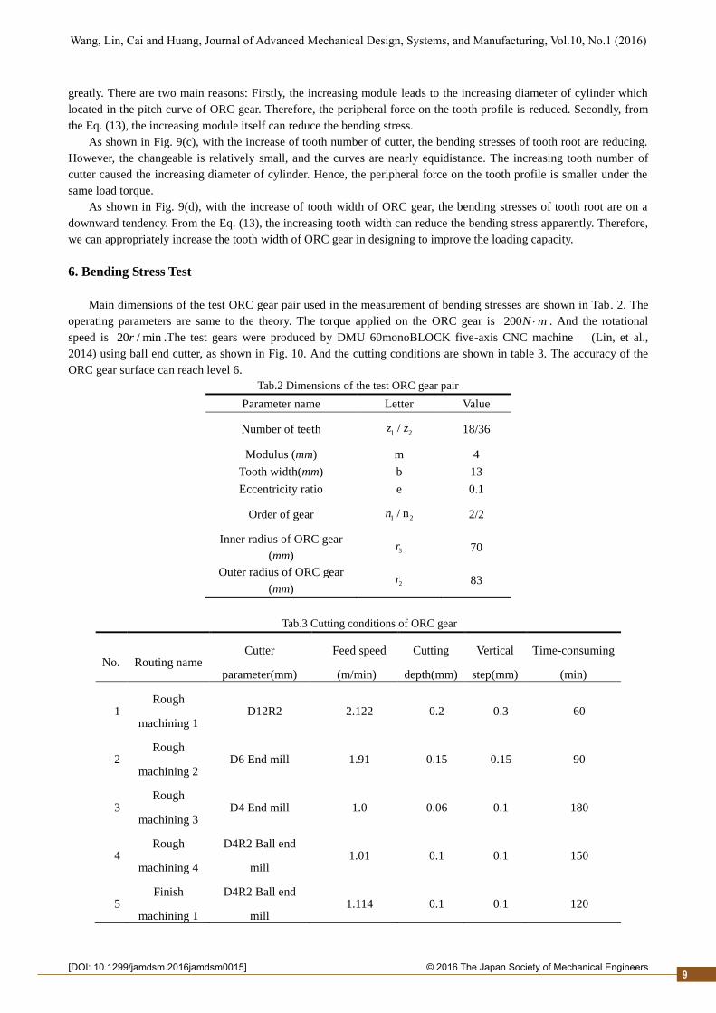
6. Bending Stress Test
Main dimensions of the test ORC gear pair used in the measurement of bending stresses are shown in Tab. 2. The
operating parameters are same to the theory. The torque applied on the ORC gear is 200N m . And the rotational
speed is 20 / minr .The test gears were produced by DMU 60monoBLOCK five-axis CNC machine (Lin, et al.,
2014) using ball end cutter, as shown in Fig. 10. And the cutting conditions are shown in table 3. The accuracy of the
ORC gear surface can reach level 6.
Tab.2 Dimensions of the test ORC gear pair
Parameter name Letter Value
Number of teeth 1 2/z z 18/36
Modulus (mm) m 4
Tooth width(mm) b 13
Eccentricity ratio e 0.1
Order of gear 1 2/ nn 2/2
Inner radius of ORC gear
(mm) 3r 70
Outer radius of ORC gear
(mm) 2r 83
Tab.3 Cutting conditions of ORC gear
No. Routing name Cutter
parameter(mm)
Feed speed
(m/min)
Cutting
depth(mm)
Vertical
step(mm)
Time-consuming
(min)
1 Rough
machining 1 D12R2 2.122 0.2 0.3 60
2 Rough
machining 2 D6 End mill 1.91 0.15 0.15 90
3 Rough
machining 3 D4 End mill 1.0 0.06 0.1 180
4 Rough
machining 4
D4R2 Ball end
mill 1.01 0.1 0.1 150
5 Finish
machining 1
D4R2 Ball end
mill 1.114 0.1 0.1 120
9

2
Wang, Lin, Cai and Huang, Journal of Advanced Mechanical Design, Systems, and Manufacturing, Vol.10, No.1 (2016)
© 2016 The Japan Society of Mechanical Engineers[DOI: 10.1299/jamdsm.2016jamdsm0015]10
No. Routing name Cutter
parameter(mm)
Feed speed
(m/min)
Cutting
depth(mm)
Vertical
step(mm)
Time-consuming
(min)
6 Finish
machining 2
D4R2 Ball end
mill 1.114 0.1 0.1 330
7 Clean angle D2R1 Ball end
mill 0.387 0.03 0.03 180
Fig.10 Machining of Curve Face Gear
Bending stresses during meshing process were measured under the static load using the strain gauge method. Three
strain gauges were pasted at the root fillet on the compressive side of the Hofer’s critical section of every ORC gear
tooth in one period as shown in Fig. 11.
Due to the experiment conditions, the compressive side of bending stresses of tooth root of second-order ORC gear
in one period is measured in this test. Using terminals to connect the strain gauges and enamel wires, after which the
resistance values between enamel wires of every gauges should be measured by multimeter. Considering the resistance
values of wires, the measured values should be about 120Ω, otherwise the connections must be checked to identify if
there are some troubles. Then connect the 30 strain gauges on ORC gear with the 60 ports of multi-channel digital
strain meter DRA-30A using the enamel wires. Non-circle gear and ORC gear are installed on the bevel gear roll tester
Y94 and adjust the center distance. Connect the PC and the DRA-30A. After balancing all the channels, exert static
pressures on the shaft of ORC gear and rotate the shaft of non-circle gear at a speed of 20r/min. Click the bottom
‘Timer on’ on the software to record the strain data which can be saved in an excel. Based on the Hooke’s law (Green,
R. E. 1992), the stresses can be obtained.
1#
2#
3#
30°
Strain gauges
mh
Fm
mSFm
Fig.11 Position of strain gauges for bending stress test
1.ORC gear 2.non-circle gear 3.Multi-channel digital strain meter DRA-30A
2.4.PC-DRA30 labview 5.bevel gear roll tester Y97

2
Wang, Lin, Cai and Huang, Journal of Advanced Mechanical Design, Systems, and Manufacturing, Vol.10, No.1 (2016)
© 2016 The Japan Society of Mechanical Engineers[DOI: 10.1299/jamdsm.2016jamdsm0015]
Fig.12 Bending stress test machine for curve face gear
Due to the characteristic of period of ORC gear, the changes of bending stresses are same in every half period
which is verified by the result of the test. Therefore, we can only analyze the variations of bending stresses in half
period. The variation of bending stresses of ORC gear in meshing process of ORC gear are shown in Fig.13 and Fig.14
The values of bending stresses measured by the static strain gauges are strain values multiplied with Young’s modulus
E=206Gpa.
950 1050 1150 1250 1350 1450 1550-720
-480
-240
0
Sampling time Ti/mSec.
-720
-480
-240
0-720
-480
-240
0
Ben
din
g s
tres
s
F/M
Pa
-720
-480
-240
0-720
-480
-240
0
2# 3#1#Tooth 1
1# 2#
2#
3#
3#
Tooth 2
1#
2#
Tooth 3
1#
1#
3#
3#
2#
Tooth 4
Tooth 5
Fig.13 Measured bending stress of ORC gear
The variations of three gauges on each tooth root in half period are shown in Fig. 13. From Fig. 13, to the ORC
gear, the stresses of big end are larger, and the stresses of tip end are smaller. This is mainly because closer the distance
to the loading point, larger the values of bending stresses are which justified the theory that the contact point of ORC
gear is located nearly the pitch curve.
900 1000 1100 1200 1300 1400 1500 1600-750
-600
-450
-300
-150
0
Sampling time Ti/mSec.
Ben
din
g s
tres
s
F/M
Pa
Tooth 1
Tooth 2
Tooth 3
Tooth 4 Tooth 5
180 195 210 225 240 255 270
300
390
480
570
660
750
Angle of non-circle gear 1/°
Ben
din
g s
tres
s
F/M
Pa
data of theory
data of test
Fig.14 Bending stresses in half period Fig.15 Comparative analysis of bending stresses
It is seen in Fig. 14 that the changes of the bending stresses values of the big end from No.1 tooth to No.5 in the
half period. From Fig. 14, the bending stresses are increasing from tooth 1 to tooth 5. Figure 15 is a comparison
diagram including the variation curve of the biggest bending stresses of the result of theory and test in half period. We
change the results of the test and the theory into absolute values to be easy to compare. There are deviations of the
results of theory and test because of the influence of manufacturing error, fixing error, testing error, etc. However, the
results of test and theory show that the stresses from the valley to peak of the pitch curve are both increasing. And the
change laws and trends are basically same. These verified the correction of the bending stress theory above.
7. Conclusion
(1) Based on the spatial engagement theory, the parametric equation of pitch curve of ORC gear is derived, and the
parametric equations of the planer pitch curve, the planer addendum curve and the planer dedendum curve are deduced.
(2) Based on the differential geometry, the changes of the principal curvatures of ORC gear are obtained. Since the
values of the curvature are relatively small, the meshing of ORC gear pair can be regarded as the meshing of non-circle
gear rack in every moment to simplify the calculation of bending stress.
(3) There are only peripheral force and axial force acting on the gear, without radial force. Hence, relative to bevel
gear, the structures of bearing and the supporting of ORC gear pair are simpler, and the vibration and impact in
meshing process are smaller, and the stability of the transmission is better. The normal force converges on the big end
of ORC gear where tooth thickness is bigger. This is good for ORC gear pair in terms of loading and bearing.
11

2
Wang, Lin, Cai and Huang, Journal of Advanced Mechanical Design, Systems, and Manufacturing, Vol.10, No.1 (2016)
© 2016 The Japan Society of Mechanical Engineers[DOI: 10.1299/jamdsm.2016jamdsm00 ]15
(4) We can choose small eccentricity ratio, large module, big tooth width and much tooth number to increase the
bending bearing capacity and avoid tooth failure in advance on condition that the request of weight and dimension of
ORC gear pair is met.
(5) The change of bending stresses of tooth root is measured using the method of strain gauges. Although there are
errors in the values of the test and theory, the tendency is same and the errors are in the allowable range. Therefore, the
correctness of the equivalent theory is verified.
Acknowledgment
The authors would like to appreciate the supports from the National Natural Science Foundation of China
(51275537).
References
Brandão, J. A., Martins, R., Seabra, J. H., & Castro, M. J. (2014). Calculation of gear tooth flank surface wear during
an FZG micropitting test.Wear, 311(1), 31-39.
Chang, S. H., Chung, T. D., & Lu, S. S. (2000). Tooth contact analysis of face-gear drives. International journal of
mechanical sciences, 42(3), 487-502.
Green, R. E. (1992). Machinery's handbook (Vol. 24). Industrial Press.
Guingand, M., De Vaujany, J. P., & Jacquin, C. Y. (2005). Quasi-static analysis of a face gear under torque. Computer
methods in applied mechanics and engineering, 194(39), 4301-4318.
Kissling U, Beermann S. Face gears: Geometry and strength[J]. Gear Technology, 2007, 1: 54-61.
K. Miyachika,B.D.I. Mohamad Nafiz and T. Asano, 2014. Root stresses and bending fatigue strength of thin-rimmed
helical gears (helix angle β0=10,20,30⁰ ). International gear conference 2014. 26-28 August 2014,Lyon
Villeurbanne, France,836-845.
Lu, J., Litvin, F. L., & Chen, J. S. (1995). Load share and finite element stress analysis for double circular-arc helical
gears. Mathematical and computer modelling, 21(10), 13-30.
Litvin, F. L., Fuentes, A., Zanzi, C., Pontiggia, M., & Handschuh, R. F. (2002). Face-gear drive with spur involute
pinion: geometry, generation by a worm, stress analysis. Computer methods in applied mechanics and
engineering, 191(25), 2785-2813.
Litvin, F. L., & Fuentes, A. (2004). Gear geometry and applied theory. Cambridge University Press.
Lin, C., Gong, H., Nie, N., Zen, Q., & Zhang, L. (2013). Geometry design, three-dimensional modeling and kinematic
analysis of orthogonal fluctuating gear ratio face gear drive. Proceedings of the Institution of Mechanical
Engineers, Part C: Journal of Mechanical Engineering Science, 227(4), 779-793.
Lin, C., NIE, L., ZENG, Q., & GONG, H. (2013). Calculation and analysis of strength for elliptical bevel gear. Journal
of Chongqing University, 8, 001.
Lin, C., Nie, L., Li, S., & Zhang, L. (2013). Strength calculation method of eccentric-high order elliptical bevel gear
pair. Jixie Gongcheng Xuebao(Chinese Journal of Mechanical Engineering), 49(5), 47-54.
Lin, C., FAN, Y., WANG, Y., CAO, X., & CAI, Z. (2014). A five-axis CNC machining method of orthogonal variable
transmission ratio face gear. Journal of Advanced Mechanical Design, Systems, and Manufacturing, 8(3),
JAMDSM0040-JAMDSM0040.
Pandya, Y., & Parey, A. (2013). Experimental investigation of spur gear tooth mesh stiffness in the presence of crack
using photoelasticity technique.Engineering Failure Analysis, 34, 488-500.
Patil, A. V., Gambhire, V. R., & Patil, P. J. (2014). Analysis of bending strength of bevel gear by FEM. Analysis, 1(6).
Sekar, R. P., & Muthuveerappan, G. (2014). Load sharing based maximum fillet stress analysis of asymmetric helical
gears designed through direct design—A parametric study. Mechanism and Machine Theory, 80, 84-102.
Verlak, M. Š. T & Glodež, S.,. Determination of bending strength of sintered spur gear made of SINT D30 powder
metal. International gear conference 2014. 26-28 August 2014,Lyon Villeurbanne, France,681-688.
Wang, Y. Z., Wu, C. H., Gong, K., Wang, S., Zhao, X. F., & Lv, Q. J. (2012). Loaded tooth contact analysis of
orthogonal face-gear drives. Proceedings of the Institution of Mechanical Engineers, Part C: Journal of
Mechanical Engineering Science, 226(9), 2309-2319.
12


![Bulletin of the JSME Journal of Thermal Science and … of the JSME Journal of Thermal Science and Technology Vol.11, No.1, 2016 Paper No.15-00529 [DOI: 10.1299/jtst.2016jtst0001]](https://static.fdocuments.in/doc/165x107/5b03e5257f8b9a0a548cc857/bulletin-of-the-jsme-journal-of-thermal-science-and-of-the-jsme-journal-of-thermal.jpg)