
Bulletin No.: Date: Recall Bulletin · Recall Bulletin Bulletin No.: Date: ... Page 2 November 2014...
20
Copyright 2014 General Motors. All Rights Reserved. Recall Bulletin Bulletin No.: Date: 14350D November 2014 PRODUCT SAFETY RECALL SUBJECT: Unintended Ignition Key Rotation MODELS: 2000-2005 Chevrolet Impala 2000-2005 Chevrolet Monte Carlo 1997-2005 Chevrolet Malibu 1999-2004 Oldsmobile Alero 1998-2002 Oldsmobile Intrigue 1999-2005 Pontiac Grand Am 2004-2008 Pontiac Grand Prix In the Parts Information section, the quantity per vehicle repair approximation for one tube of Loctite Adhesive 426™ has been changed from 125 to 100 vehicles. In the Service Procedure section, the first bullet in the note at the beginning of procedure has been modified to clarify that either repair is acceptable and may be performed at the dealer’s discretion. New photographs and text have also been added on pages 8 and 14. Additionally, a copy of the customer notification letter is now included. Please discard all copies of 14350C. It is a violation of Federal law for a dealer to deliver a new motor vehicle or any new or used item of motor vehicle equipment (including a tire) covered by this notification under a sale or lease until the defect or noncompliance is remedied. All involved vehicles that are in dealer inventory must be held and not delivered to customers, dealer traded, or used for demonstration purposes until the repair contained in this bulletin has been performed on the vehicle. CONDITION General Motors has decided that a defect which relates to motor vehicle safety exists in all 2000- 2005 model year (MY) Chevrolet Impala and Monte Carlo, 1997-2005 MY Chevrolet Malibu, 1999-2004 MY Oldsmobile Alero, 1998-2002 MY Oldsmobile Intrigue, 1999-2005 MY Pontiac Grand Am and 2004-2008 MY Pontiac Grand Prix vehicles. If the key ring is carrying added weight and the vehicle goes off road or experiences some other jarring event, it may unintentionally move the key away from the “run” position. If this occurs, engine power, power steering and power braking will be affected, increasing the risk of a crash. If the ignition switch is not in the run position, the air bags may not deploy if the vehicle is involved in a crash, increasing the risk of injury or fatality.
Transcript of Bulletin No.: Date: Recall Bulletin · Recall Bulletin Bulletin No.: Date: ... Page 2 November 2014...

Copyright 2014 General Motors. All Rights Reserved.
Recall Bulletin
Bulletin No.: Date:
14350D November 2014
PRODUCT SAFETY RECALL SUBJECT: Unintended Ignition Key Rotation
MODELS: 2000-2005 Chevrolet Impala 2000-2005 Chevrolet Monte Carlo 1997-2005 Chevrolet Malibu 1999-2004 Oldsmobile Alero 1998-2002 Oldsmobile Intrigue 1999-2005 Pontiac Grand Am 2004-2008 Pontiac Grand Prix
In the Parts Information section, the quantity per vehicle repair approximation for one tube of Loctite Adhesive 426™ has been changed from 125 to 100 vehicles. In the Service Procedure section, the first bullet in the note at the beginning of procedure has been modified to clarify that either repair is acceptable and may be performed at the dealer’s discretion. New photographs and text have also been added on pages 8 and 14. Additionally, a copy of the customer notification letter is now included. Please discard all copies of 14350C.
It is a violation of Federal law for a dealer to deliver a new motor vehicle or any new or used item of motor vehicle equipment (including a tire) covered by this notification under a sale or lease until the defect or noncompliance is remedied.
All involved vehicles that are in dealer inventory must be held and not delivered to customers, dealer traded, or used for demonstration purposes until the repair contained in this bulletin has been performed on the vehicle.
CONDITION
General Motors has decided that a defect which relates to motor vehicle safety exists in all 2000-2005 model year (MY) Chevrolet Impala and Monte Carlo, 1997-2005 MY Chevrolet Malibu, 1999-2004 MY Oldsmobile Alero, 1998-2002 MY Oldsmobile Intrigue, 1999-2005 MY Pontiac Grand Am and 2004-2008 MY Pontiac Grand Prix vehicles. If the key ring is carrying added weight and the vehicle goes off road or experiences some other jarring event, it may unintentionally move the key away from the “run” position. If this occurs, engine power, power steering and power braking will be affected, increasing the risk of a crash. If the ignition switch is not in the run position, the air bags may not deploy if the vehicle is involved in a crash, increasing the risk of injury or fatality.

Page 2 November 2014 Bulletin No.: 14350D
CORRECTION
Dealers are to install two 16mm outer diameter key rings and an insert in the key slot or a cover over the key head on all ignition keys.
VEHICLES INVOLVED
All involved vehicles are identified by Vehicle Identification Number on the Investigate Vehicle History screen in GM Global Warranty Management system. Dealership service personnel should always check this site to confirm vehicle involvement prior to beginning any required inspections and/or repairs. It is important to routinely use this tool to verify eligibility because not all similar vehicles may be involved regardless of description or option content.
For dealers with involved vehicles, a listing with involved vehicles containing the complete vehicle identification number, customer name, and address information has been prepared and will be provided to U.S. and Canadian dealers through the GM GlobalConnect Recall Reports, or sent directly to export dealers. Dealers will not have a report available if they have no involved vehicles currently assigned.
The listing may contain customer names and addresses obtained from Motor Vehicle Registration Records. The use of such motor vehicle registration data for any purpose other than follow-up necessary to complete this recall is a violation of law in several states/provinces/countries. Accordingly, you are urged to limit the use of this report to the follow-up necessary to complete this recall. PART INFORMATION
For U.S. and Canada The pre-shipment of GMCCA components (key inserts, key cover kits and key rings) has concluded. Dealers may begin placing orders for these parts starting September 24, 2014. Dealers should place orders via the Parts Workbench or EPIC using DRO or CSO. There is no need to place a CSO-3 order as stock will be available at your local PDC. Orders will process within the normal standards of service. Refer to answerbacks and/or order status inquiries for order information. Orders will continue to be monitored by GMCCA.
Dealers should continue to order the Loctite® and 3M products from ExodusDirect by visiting their website at www.oemhelper.com or calling 844-596-9428.
For Export If the Loctite® and 3M products cannot be obtained from ExodusDirect, please try to obtain from a regional distributor. For the parts supplied by GMCCA, customers should begin normal ordering. Orders will be monitored.
Please note, key ring orders may be fulfilled with any one of the key ring part numbers listed below, even if it is not the specific part that was ordered.

Page 3 November 2014 Bulletin No.: 14350D
For Service Option #1 - Install Two 16mm Key Rings and an Insert in the Key Slot
Part Number Description Quantity/Vehicle
23279477 Key Insert (Pack of 4) 4
Obtain From ExodusDirect
Loctite Adhesive 426™ 1 tube fixes approx. 100
vehicles
Obtain From ExodusDirect
Loctite Primer 770™ 1 bottle fixes approx. 250
vehicles
23247262 *
or
23232599
or
13598784
Key Ring (Pack of 4)
4 Rings (2 Per Key)
* Stock is now exhausted for this part number. Please direct your key ring orders to part numbers 23232599 or 13598784.
Note: Since only a small number of vehicles will require key replacement, dealers are encouraged not to order service keys for shelf stock. If a service key is required, dealers should refer to the GM Electronic Parts Catalog (EPC) for service key part number information and order accordingly from GMCCA.
For Service Option #2 – Install Two 16mm Key Rings and a Cover over the Key Head
Part Number Description Quantity/Vehicle
23279476 Key Cover Kit (Includes Two Front and Rear Covers) 1
Obtain From ExodusDirect
3M™ Scotch-Weld™ DP8805NS Adhesive
3M™ Part Number 68958
1 Bottle fixes approx. 6 vehicles
Obtain From ExodusDirect
Static Mixing Nozzle for 3M™ Scotch-Weld™ Adhesives 3M™ Part Number 69043
1 nozzle per vehicle
Obtain From ExodusDirect
3M™ Performance Manual Applicator, 50mL
3M™ Part Number 08190
N/A
(Usage Unlimited)
Obtain From ExodusDirect
10:1 Ratio Plunger for 3M™ Scotch-Weld™ Adhesives 3M™ Part Number 69044
N/A
(Usage Unlimited)
23247262 *
or
23232599
or
13598784
Key Ring (Pack of 4)
4 Rings (2 Per Key)
* Stock is now exhausted for this part number. Please direct your key ring orders to part numbers 23232599 or 13598784.

Page 4 November 2014 Bulletin No.: 14350D
Note: Since only a small number of vehicles will require key replacement, dealers are encouraged not to order service keys for shelf stock. If a service key is required, dealers should refer to the GM Electronic Parts Catalog (EPC) for service key part number information and order accordingly from GMCCA.
SERVICE PROCEDURE
Note: Carefully read and follow the instructions below.
Use either the key insert repair or two-piece key cover repair procedure to repair most customer-provided keys. Both repair methods are GM-approved repairs. Product availability, customer preference, and key design requirements will determine which key repair method to use.
Before performing the key repair, inspect the ignition lock cylinder to determine if it has two “ears” protruding from the cylinder. If the lock cylinder has ears, perform the key insert repair only.
Some keys will NOT be able to be repaired using the key insert repair. Use the two piece key cover kit to repair keys that cannot be repaired using the insert key repair.
In the rare instance that keys cannot be repaired, order new service keys for the customer-provided keys. Do NOT order new service keys unless BOTH repair methods have been attempted.
The new service keys may have to be modified as instructed in this bulletin.
If the new service key has a slot design for the key ring, it MUST be repaired using the key insert or two-piece key cover repair.
If the new service key has a round hole or square design for the key ring, no key modification is required. Install two 16mm key rings as instructed in the service procedure.
If a customer presents additional keys for modification (more than 2 keys), perform the key insert repair or the two-piece key cover repair and route the warranty transaction for wholesale authorization.
If a customer presents a valet key for modification, perform the key insert repair only and route the warranty transaction for wholesale authorization. Do not attempt the two-piece key cover repair. Valet keys are easily distinguish from standard keys by their gray color and the word “Valet” imprinted on them.

Page 5 November 2014 Bulletin No.: 14350D
Key Insert Repair
3970365
Note: Locate the four key inserts and four 16 mm rings. Two key inserts are required to modify one key. Two 16mm key rings are required for each key repair.
Note: If the key slot is too small or large for the insert, use the two-piece key cover repair. If the head of the insert does not cover the entire slot, the key insert repair cannot be used.
1. Test fit the customer-provided key. Insert a key insert into the front slot of the key and insert a second key insert into the back slot of the key. Ensure the key insert fits flush into the slot of both sides of the key.
2. Remove the inserts from the front and back key slots.
3970395
Caution: Do NOT use petroleum-based cleaning products to clean the key or key covers.
3. Clean the head and slot of the keys using a shop towel and isopropyl alcohol.

Page 6 November 2014 Bulletin No.: 14350D
3970397
4. Clean the key inserts using a shop towel and isopropyl alcohol.
Caution: Allow the primer to dry for 5 minutes BEFORE proceeding to step 7 to ensure the adhesive will provide a strong bond between the key insert and the slot of the key.
Note: The adhesive for this repair begins to cure quickly. It is essential that both keys are repaired promptly. Ensure all of the required tools, parts and supplies are on your work bench BEFORE attempting to apply primer and adhesive to the key slots and key inserts. The following items should be on the work bench:
Rubber gloves and shop towels
Adhesive
Key inserts
Two rings for each key
Spring clamp with rubber ends
3970399
5. Apply the primer to the front and back key slot of the two keys.
6. Apply the primer to the four inserts.

Page 7 November 2014 Bulletin No.: 14350D
3970372
7. Apply adhesive to the corners (3) of the key slots.
8. Apply adhesive to the post (1) and hole (2) of each insert.
3970401
9. Insert a front and back insert to the key slot of each key.
10. Clean the body of the keys with a shop towel.
11. Clean the hole of each key with a shop towel and screwdriver.
3970376
12. Clamp the two key insert to the key slot using a spring clamp with rubber ends.

Page 8 November 2014 Bulletin No.: 14350D
13. Remove the clamp from the key assembly after allowing the adhesive to dry for 5 minutes.
4021807
14. Install two 16 mm key rings to the key. Attach the first 16 mm ring to the key hole. Attach the second 16 mm ring to the first 16 mm ring. Refer to photograph.
4022120
15. After allowing the key insert to dry for 24 hours, install the key fob to the key assembly as shown in the photograph. Do NOT add larger key rings to the assembly. Refer to the owner manual supplement for information about the ignition key assembly.
16. Make a copy to the owner manual supplement on the last page of this bulletin and insert it into the vehicle’s owner manual.
Note: Do not re-attach the fob or any other keys to the second 16 mm ring. Instruct the customer not to attach the fob or any other keys to the second ring for approximately 24-hours to allow the adhesive to reach maximum holding strength. Customers are to refer to the owner manual supplement for proper attachment instructions.

Page 9 November 2014 Bulletin No.: 14350D
Two-Piece Key Cover Repair
3971048
Note: Locate the four key covers and four 16 mm rings. A front and back cover are required to modify one key. Two 16mm key rings are required for each key repair.
3971010
Note: There is a front and back key cover. The front key cover has a GM logo on it (1). The back key cover is blank (2).

Page 10 November 2014 Bulletin No.: 14350D
3971023
1. Test fit the customer-provided key into the back key cover.
1.1 Ensure the body of the key fits into the back key cover. The body of the key may require some filing to fit into the cover. Use a file to remove the material from the body of the key.
1.2 Align the back cover boss (1) with the slot (2) of the customer-provided key.
1.3 Using a pen or knife mark the top portion of the slot (3) that must be cut in order for the customer-provided key to fit inside of the back cover.
3971044
1.4 Using a knife or box cutter, cut out a notch (A) in the slot of the key.
1.5 The back cover boss must fit inside of the notched area of the key (B).
1.6 Remove the key from the back cover.

Page 11 November 2014 Bulletin No.: 14350D
3971005
Caution: Do NOT use petroleum-based cleaning products to clean the key or key covers.
2. Clean the head and slot of the keys using a shop towel and isopropyl alcohol.
3. Clean the front and back key covers using a shop towel and isopropyl alcohol.
Note: The adhesive for this repair begins to cure quickly. It is essential that both keys are repaired promptly. Ensure all of the required tools, parts and supplies are on your work bench BEFORE attempting to assemble the key covers over the key. The following items should be on the work bench:
Adhesive
A front and back key cover for each key
File
Shop towels and rubber gloves
Two rings for each key
Spring clamp with rubber ends
Note: Use a small flat bladed screwdriver to separate the two covers. Insert the screwdriver into the key blade opening of the cover. Turn the screw driver to separate the two covers.
4. Assemble the front and back key cover over the key. Ensure the front and back cover fit over the key and that the two covers snap together.
If the key covers fit over the key and snap together correctly, proceed to step 5.
If the key covers do NOT fit over the key, file more material off the body of the key. Re-assemble the key covers over the key to ensure proper cover fit. Clean the key and covers BEFORE applying the adhesive.

Page 12 November 2014 Bulletin No.: 14350D
3971030
5. Dispense a small amount of adhesive to ensure the mixed adhesive is blue or green (not white or brown) in color. Then apply a bead of adhesive to the inside of the front and back key cover. Ensure a bead of adhesive is applied to the whole perimeter of the cover.
3970991
6. Press the front and back key cover over the key.

Page 13 November 2014 Bulletin No.: 14350D
3971005
7. Remove excess adhesive from the body of the key using a shop towel and isopropyl alcohol.
8. Remove excess adhesive from the hole of the front and back key cover using a shop towel and small screwdriver.
3970997
9. Clamp the two covers together using a spring clamp with rubber ends.
10. Allow the adhesive to dry for 30 minutes before removing the spring clamp from the key assembly.

Page 14 November 2014 Bulletin No.: 14350D
4023353
11. Install two 16 mm key rings to the key. Attach the first 16 mm ring to the key hole. Attach the second 16 mm ring to the first 16mm ring. Refer to photograph.
4023355
12. After allowing the key insert to dry for 24 hours, install the fob to the key assembly as shown in the photograph. Do NOT add larger key rings to the assembly. Refer to the owner manual supplement for information about the ignition key assembly.
13. Make a copy to the owner manual supplement on the last page of this bulletin and insert it into the vehicle’s owner manual.
Note: Do not re-attach the fob or any other keys to the second 16 mm ring. Instruct the customer not to attach the fob or any other keys to the second ring for approximately 24-hours to allow the adhesive to reach maximum holding strength. Customers are to refer to the owner manual supplement for proper attachment instructions.

Page 15 November 2014 Bulletin No.: 14350D
COURTESY TRANSPORTATION – For U.S. and Canada
The General Motors Courtesy Transportation program is intended to minimize customer inconvenience when a vehicle requires a repair that is covered by the New Vehicle Limited Warranties. The availability of courtesy transportation to customers whose vehicles are within the warranty coverage period and involved in a product program is very important in maintaining customer satisfaction. Dealers are to ensure that these customers understand that shuttle service or some other form of courtesy transportation is available and will be provided at no charge. Dealers should refer to the General Motors Service Policies and Procedures Manual for Courtesy Transportation guidelines. WARRANTY TRANSACTION INFORMATION
Submit a transaction using the table below. All transactions should be submitted as a ZFAT transaction type, unless noted otherwise.
Labor Code Description
Labor Time
Net Item
9100755 Install Key Insert and Key Rings (Two Keys) 0.4 *
9100880 Install Key Cover and Key Rings (Two Keys)
Add: 0.1-0.3 to Modify Key to Fit Key Cover
0.4 **
9100881 Insert Test Fit Unsuccessful – Repair Not Workable
Install Key Cover and Key Rings (Two Keys)
Add: 0.1-0.3 to Modify Key to Fit Key Cover (If Required)
0.5 **
9100882 Service Keys (Round Hole or Square Design)
Add: 0.1-0.3 to Modify Key to Fit Key Cover (If Required)
Includes: Insert Test Fit, Key Cover Repair and Cutting Two Keys - Service Key Modification Not Required
0.8 N/A
9100883 Service Keys (Slot Design)
Add: 0.1-0.3 to Modify Key to Fit Key Cover if required
Includes: Insert Test Fit, Key Cover Repair and Cutting Two Keys - Service Key Modification Required
1.2 N/A
9100959 Purchase 3M Applicator Gun and Plunger (One Time Purchase For Canada and Export Only)
N/A ***
Note: Most keys will NOT require much filing to fit into the key covers. The 0.4 base time includes time to perform minor filing for correct key-to-cover fit. Only use the add time for repairs that require a substantial amount of filing time.
Note: Since usage of the 3M applicator gun and plunger is unlimited, their acquisition from ExodusDirect or a regional distributor is considered a one-time buy. This means that GM will reimburse the dealer only once for their purchase. Any additional applicator guns and plungers purchased will be a dealer expense and not covered by this recall. All U.S. dealers received a 3M applicator gun and plunger as part of the parts pre-shipment at no charge.
Note: If a customer presents additional keys for modification (more than 2 keys), perform either repair. For a valet key modification, perform the key insert repair only. Route the warranty transaction for wholesale authorization.

Page 16 November 2014 Bulletin No.: 14350D
* The amount identified in “Net Item” should represent the actual sum total of the cost for the Loctite adhesive and primer needed to perform the required repairs, not to exceed $0.21 USD, $0.23 CAD.
** The amount identified in “Net Item” should represent the actual sum total of the cost for the
3M adhesive and nozzle needed to perform the required repairs, not to exceed $3.08 USD, $3.48 CAD.
*** For Canada and Export Only: The amount identified in “Net Item” should represent the actual
sum total of the cost for the 3M applicator gun and plunger needed to perform the required repairs, not to exceed $65.00 CAD. The 3M applicator gun and plunger are also used to perform the same repair on vehicles involved in safety recalls 14172 and 14299. If a transaction has already been submitted under either one of those recalls for the purchase of the 3M applicator gun and plunger, do not attempt to submit another transaction under this recall as it will be rejected.
CUSTOMER NOTIFICATION – For U.S. and Canada
General Motors will notify customers of this recall on their vehicle (see copy of customer letter included with this bulletin). CUSTOMER NOTIFICATION – For Export
Letters will be sent to known owners of record located within areas covered by the U.S. National Traffic and Motor Vehicle Safety Act. For owners outside these areas, dealers should notify customers using the attached sample letter. DEALER RECALL RESPONSIBILITY – For U.S. and Export (U.S. States, Territories,
and Possessions)
It is a violation of Federal law for a dealer to deliver a new motor vehicle or any new or used item of motor vehicle equipment (including a tire) covered by this notification under a sale or lease until the defect or noncompliance is remedied.
The U.S. National Traffic and Motor Vehicle Safety Act provides that each vehicle that is subject to a recall of this type must be adequately repaired within a reasonable time after the customer has tendered it for repair. A failure to repair within sixty days after tender of a vehicle is prima facie evidence of failure to repair within a reasonable time. If the condition is not adequately repaired within a reasonable time, the customer may be entitled to an identical or reasonably equivalent vehicle at no charge or to a refund of the purchase price less a reasonable allowance for depreciation. To avoid having to provide these burdensome remedies, every effort must be made to promptly schedule an appointment with each customer and to repair their vehicle as soon as possible. In the recall notification letters, customers are told how to contact the U.S. National Highway Traffic Safety Administration if the recall is not completed within a reasonable time. DEALER RECALL RESPONSIBILITY – All
All unsold new vehicles in dealers' possession and subject to this recall must be held and inspected/repaired per the service procedure of this recall bulletin before customers take possession of these vehicles.
Dealers are to service all vehicles subject to this recall at no charge to customers, regardless of mileage, age of vehicle, or ownership, from this time forward.

Page 17 November 2014 Bulletin No.: 14350D
Customers who have recently purchased vehicles sold from your vehicle inventory, and for which there is no customer information indicated on the dealer listing, are to be contacted by the dealer. Arrangements are to be made to make the required correction according to the instructions contained in this bulletin. A copy of the customer letter is provided in this bulletin for your use in contacting customers. Program follow-up cards should not be used for this purpose, since the customer may not as yet have received the notification letter.
In summary, whenever a vehicle subject to this recall enters your vehicle inventory, or is in your dealership for service in the future, you must take the steps necessary to be sure the recall correction has been made before selling or releasing the vehicle.
GM bulletins are intended for use by professional technicians, NOT a "do-it-yourselfer". They are written to inform these technicians of conditions that
may occur on some vehicles, or to provide information that could assist in the proper service of a vehicle. Properly trained technicians have the tools,
equipment, safety instructions, and know-how to do a job properly and safely. If a condition is described, DO NOT assume that the bulletin applies to
your vehicle, or that your vehicle will have that condition. See your dealer for information on whether your vehicle may benefit from the information.
We Support
Voluntary Technician
Certification

Page 18 November 2014 Bulletin No.: 14350D
IMPORTANT SAFETY RECALL
September 2014
Dear General Motors Customer:
This notice is sent to you in accordance with the National Traffic and Motor Vehicle Safety Act.
General Motors has decided that a defect which relates to motor vehicle safety exists in your 2000-2005 model year (MY) Chevrolet Impala or Monte Carlo, 1997-2005 MY Chevrolet Malibu, 1999-2004 MY Oldsmobile Alero, 1998-2002 MY Oldsmobile Intrigue, 1999-2005 MY Pontiac Grand Am or 2004-2008 MY Pontiac Grand Prix vehicle. As a result, GM is conducting a safety recall. We apologize for this inconvenience. However, we are concerned about your safety and continued satisfaction with our products.
I M P O R T A N T
This notice applies to your vehicle.
Your vehicle is involved in GM safety recall 14350.
Until the recall has been performed, it is very important that you remove all items from your key ring, leaving only the vehicle key. The key fob (if applicable), should also be removed from the key ring.
Schedule an appointment with your Cadillac dealer as soon as possible.
This service will be performed for you at no charge.
Why is your vehicle being recalled?
If the key ring is carrying added weight and the vehicle goes off road or experiences some other jarring event, it may unintentionally move the key away from the “run” position. If this occurs, engine power, power steering and power braking may be affected, increasing the risk of a crash. If the ignition switch is not in the run position, the air bags may not deploy if the vehicle is involved in a crash, increasing the risk of injury or fatality.
What will we do?
Your GM dealer will install two key rings and an insert in the key slot or a cover over the key head on all ignition keys. This service will be performed for you at no charge. Because of scheduling requirements, it is likely that your dealer will need your vehicle longer than the actual service correction time of approximately 15 minutes.
Also included with this letter is an owner manual supplement. Please review this document and retain it with your vehicle’s owner manual.
Page 19 November 2014 Bulletin No.: 14350D
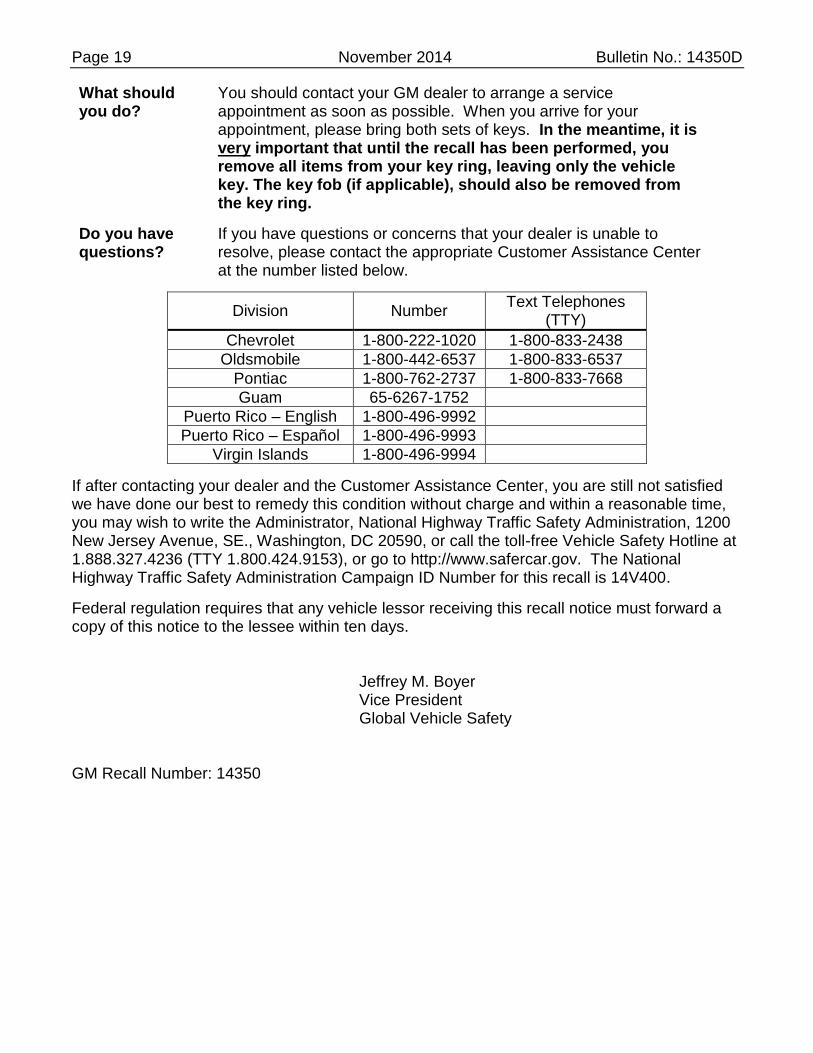
What should you do?
You should contact your GM dealer to arrange a service appointment as soon as possible. When you arrive for your appointment, please bring both sets of keys. In the meantime, it is very important that until the recall has been performed, you remove all items from your key ring, leaving only the vehicle key. The key fob (if applicable), should also be removed from the key ring.
Do you have questions?
If you have questions or concerns that your dealer is unable to resolve, please contact the appropriate Customer Assistance Center at the number listed below.
Division Number Text Telephones
(TTY)
Chevrolet 1-800-222-1020 1-800-833-2438
Oldsmobile 1-800-442-6537 1-800-833-6537
Pontiac 1-800-762-2737 1-800-833-7668
Guam 65-6267-1752
Puerto Rico – English 1-800-496-9992
Puerto Rico – Español 1-800-496-9993
Virgin Islands 1-800-496-9994
If after contacting your dealer and the Customer Assistance Center, you are still not satisfied we have done our best to remedy this condition without charge and within a reasonable time, you may wish to write the Administrator, National Highway Traffic Safety Administration, 1200 New Jersey Avenue, SE., Washington, DC 20590, or call the toll-free Vehicle Safety Hotline at 1.888.327.4236 (TTY 1.800.424.9153), or go to http://www.safercar.gov. The National Highway Traffic Safety Administration Campaign ID Number for this recall is 14V400.
Federal regulation requires that any vehicle lessor receiving this recall notice must forward a copy of this notice to the lessee within ten days.
Jeffrey M. Boyer Vice President Global Vehicle Safety
GM Recall Number: 14350

Page 20 November 2014 Bulletin No.: 14350D
REPRODUCE LOCALLY - INSERT IN VEHICLE’S OWNER MANUAL
3973594


