BUILDING SERVICES ( AE 303 ) 1. ELECTRICAL
125
BUILDING SERVICES ( AE 303 ) 1. ELECTRICAL What is Electrical Wiring? Electrical Wiring is a process of connecting cables and wires to the related devices such as fuse, switches, sockets, lights, and fans etc. to the main distribution board in a specific structure to ensure continuous power supply. Methods of Electrical Wiring Systems Wiring (a process of connecting various accessories for distribution of electrical energy from supplier’s meter board to home appliances such as lamps, fans and other domestic appliances is known as Electrical Wiring) can be done using two methods which are Joint box system or Tee system Loop – in system They are discussed as follows: Joint Box or Tee or Jointing System In this method of wiring, connections to appliances are made through joints. These joints are made in joint boxes by means of suitable connectors or joints cutouts. This method of wiring doesn’t consume too much cables size. You might think because this method of wiring doesn’t require too much cable it is therefore cheaper. It is of course but the money you saved from buying cables will be used in buying joint boxes, thus equation is balanced. This method is suitable for temporary installations and it is cheap.
Transcript of BUILDING SERVICES ( AE 303 ) 1. ELECTRICAL

BUILDING SERVICES ( AE 303 )
1. ELECTRICAL
What is Electrical Wiring?
Electrical Wiring is a process of connecting cables and wires to the related devices such as fuse,
switches, sockets, lights, and fans etc. to the main distribution board in a specific structure to
ensure continuous power supply.
Methods of Electrical Wiring Systems
Wiring (a process of connecting various accessories for distribution of electrical energy from
supplier’s meter board to home appliances such as lamps, fans and other domestic appliances
is known as Electrical Wiring) can be done using two methods which are
Joint box system or Tee system Loop – in system
They are discussed as follows:
Joint Box or Tee or Jointing System
In this method of wiring, connections to appliances are made through joints. These joints are
made in joint boxes by means of suitable connectors or joints cutouts. This method of wiring
doesn’t consume too much cables size.
You might think because this method of wiring doesn’t require too much cable it is therefore
cheaper. It is of course but the money you saved from buying cables will be used in buying joint
boxes, thus equation is balanced. This method is suitable for temporary installations and it is
cheap.

Loop-in or Looping System
This method of wiring is universally used in wiring. Lamps and other appliances are connected
in parallel so that each of the appliances can be controlled individually. When a connection is
required at a light or switch, the feed conductor is looped in by bringing it directly to the
terminal and then carrying it forward again to the next point to be fed.
The switch and light feeds are carried round the circuit in a series of loops from one point to
another until the last on the circuit is reached. The phase or line conductors are looped either in
switchboard or box and neutrals are looped either in switchboard or from light or fan. Line or
phase should never be looped from light or fan.

Advantages of Loop-In Method of Wiring
It doesn’t require joint boxes and so money is saved
In loop – in systems, no joint is concealed beneath floors or in roof spaces.
Fault location is made easy as the points are made only at outlets so that they are accessible.
Disadvantages of Loop-In Method of Wiring
Length of wire or cables required is more and voltage drop and copper losses are therefore more
Looping – in switches and lamp holders is usually difficult.
Related Posts:
Types of Diodes and Their Applications Different Types Of Relays, Their Construction, Operation & Applications Different Types of Electrical Wiring Systems
The types of internal wiring usually used are
Cleat wiring Wooden casing and capping wiring CTS or TRS or PVC sheath wiring Lead sheathed or metal sheathed wiring Conduit wiring
There are additional types of conduit wiring according to Pipes installation (Where steel and
PVC pipes are used for wiring connection and installation).
Surface or open Conduit type
Recessed or concealed or underground type Conduit
Cleat Wiring
This system of wiring comprise of ordinary VIR or PVC insulated wires (occasionally, sheathed
and weather proof cable) braided and compounded held on walls or ceilings by means of
porcelain cleats, Plastic or wood.
Cleat wiring system is a temporary wiring system therefore it is not suitable for domestic
premises. The use of cleat wiring system is over nowadays.

Advantages of Cleat Wiring:
It is simple and cheap wiring system
Most suitable for temporary use i.e. under construction building or army camping
As the cables and wires of cleat wiring system is in open air, Therefore fault in cables can be seen and repair easily.
Cleat wiring system installation is easy and simple.
Customization can be easily done in this wiring system e.g. alteration and addition.
Inspection is easy and simple.
Disadvantages of Cleat Wiring:
Appearance is not so good.
Cleat wiring can’t be use for permanent use because, Sag may be occur after sometime of the usage.

In this wiring system, the cables and wiring is in open air, therefore, oil, Steam, humidity, smoke, rain, chemical and acidic effect may damage the cables and wires.
it is not lasting wire system because of the weather effect , risk of fire and wear & tear.
it can be only used on 250/440 Volts on low temperature.
There is always a risk of fire and electric shock.
it can’t be used in important and sensitive location and places.
It is not lasting, reliable and sustainable wiring system.
Casing and Capping wiring
Casing and Capping wiring system was famous wiring system in the past but, it is considered
obsolete this days because of Conduit and sheathed wiring system. The cables used in this kind
of wiring were either VIR or PVC or any other approved insulated cables.
The cables were carried through the wooden casing enclosures. The casing is made up of a strip
of wood with parallel grooves cut length wise so as to accommodate VIR cables. The grooves
were made to separate opposite polarity. the capping (also made of wood) used to cover the
wires and cables installed and fitted in the casing.
Advantages of Casing Capping Wiring:
It is cheap wiring system as compared to sheathed and conduit wiring systems.
It is strong and long-lasting wiring system.
Customization can be easily done in this wiring system.
If Phase and Neutral wire is installed in separate slots, then repairing is easy.

Stay for long time in the field due to strong insulation of capping and casing..
It stays safe from oil, Steam, smoke and rain. No risk of electric shock due to covered wires and cables in casing & capping.
Disadvantages Casing Capping Wiring:
There is a high risk of fire in casing & capping wiring system.
Not suitable in the acidic, alkalies and humidity conditions
Costly repairing and need more material.
Material can’t be found easily in the contemporary White ants may damage the casing & capping of wood.
Batten Wiring (CTS or TRS)
Single core or double core or three core TRS cables with a circular oval shape cables are used in
this kind of wiring. Mostly, single core cables are preferred. TRS cables are chemical proof,
water proof, steam proof, but are slightly affected by lubricating oil. The TRS cables are run on
well seasoned and straight teak wood batten with at least a thickness of 10mm.
The cables are held on the wooden batten by means of tinned brass link clips (buckle clip)
already fixed on the batten with brass pins and spaced at an interval of 10cm for horizontal
runs and 15cm for vertical runs.
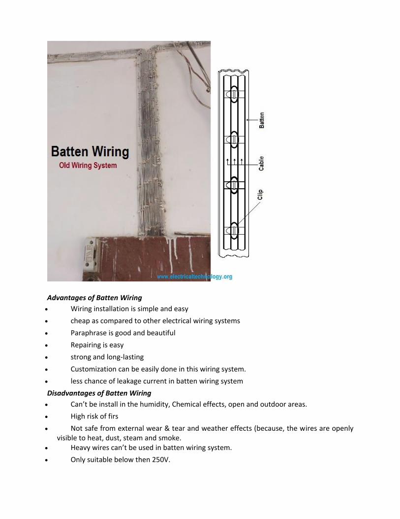
Advantages of Batten Wiring
Wiring installation is simple and easy
cheap as compared to other electrical wiring systems
Paraphrase is good and beautiful
Repairing is easy
strong and long-lasting
Customization can be easily done in this wiring system.
less chance of leakage current in batten wiring system
Disadvantages of Batten Wiring
Can’t be install in the humidity, Chemical effects, open and outdoor areas.
High risk of firs
Not safe from external wear & tear and weather effects (because, the wires are openly visible to heat, dust, steam and smoke.
Heavy wires can’t be used in batten wiring system.
Only suitable below then 250V.

Need more cables and wires.
Lead Sheathed Wiring
The type of wiring employs conductors that are insulated with VIR and covered with an outer
sheath of lead aluminum alloy containing about 95% of lead. The metal sheath given protection
to cables from mechanical damage, moisture and atmospheric corrosion.
The whole lead covering is made electrically continuous and is connected to earth at the point
of entry to protect against electrolytic action due to leaking current and to provide safety in
case the sheath becomes alive. The cables are run on wooden batten and fixed by means of link
clips just as in TRS wiring.
Conduit Wiring
There are two additional types of conduit wiring according to pipe installation
Surface Conduit Wiring Concealed Conduit Wiring
Surface Conduit Wiring
If conduits installed on roof or wall, It is known as surface conduit wiring. in this wiring method,
they make holes on the surface of wall on equal distances and conduit is installed then with the
help of rawal plugs.
Concealed Conduit wiring
If the conduits is hidden inside the wall slots with the help of plastering, it is called concealed
conduit wiring. In other words, the electrical wiring system inside wall, roof or floor with the
help of plastic or metallic piping is called concealed conduit wiring. obliviously, It is the most
popular, beautiful, stronger and common electrical wiring system nowadays.

In conduit wiring, steel tubes known as conduits are installed on the surface of walls by means
of pipe hooks (surface conduit wiring) or buried in walls under plaster and VIR or PVC cables are
afterwards drawn by means of a GI wire of size if about 18SWG.
In Conduit wiring system, The conduits should be electrically continuous and connected to
earth at some suitable points in case of steel conduit. Conduit wiring is a professional way of
wiring a building. Mostly PVC conduits are used in domestic wiring.
The conduit protects the cables from being damaged by rodents (when rodents bites the cables
it will cause short circuit) that is why circuit breakers are in place though but hey! Prevention is
better than cure. Lead conduits are used in factories or when the building is prone to fire
accident. Trunking is more of like surface conduit wiring. It’s gaining popularity too.
It is done by screwing a PVC trunking pipe to a wall then passing the cables through the pipe.
The cables in conduit should not be too tight. Space factor have to be put into consideration.
Types of Conduit
Following conduits are used in the conduit wiring systems (both concealed and surface conduit
wiring) which are shown in the above image.

Metallic Conduit Non-metallic conduit Metallic Conduit:
Metallic conduits are made of steel which are very strong but costly as well.
There are two types of metallic conduits.
Class A Conduit: Low gauge conduit (Thin layer steel sheet conduit)
Class B Conduit: High gauge conduit (Thick sheet of steel conduit)
Non-metallic Conduit:
A solid PVC conduit is used as non-metallic conduit now a days, which is flexible and easy to
bend.
Size of Conduit:
The common conduit pipes are available in different sizes genially, 13, 16.2, 18.75, 20, 25, 37,
50, and 63 mm (diameter) or 1/2, 5/8, 3/4, 1, 1.25, 1.5, and 2 inch in diameter.
Advantage of Conduit Wiring Systems
It is the safest wiring system (Concealed conduit wring)
Appearance is very beautiful (in case of concealed conduit wiring)
No risk of mechanical wear & tear and fire in case of metallic pipes.
Customization can be easily done according to the future needs.
Repairing and maintenance is easy.
There is no risk of damage the cables insulation. it is safe from corrosion (in case of PVC conduit) and risk of fire.
It can be used even in humidity , chemical effect and smoky areas.
No risk of electric shock (In case of proper earthing and grounding of metallic pipes). It is reliable and popular wiring system. sustainable and long-lasting wiring system.
Disadvantages of Conduit Wiring Systems
It is expensive wiring system (Due to PVC and Metallic pipes, Additional earthing for metallic pipes Tee(s) and elbows etc.
Very hard to find the defects in the wiring.
installation is not easy and simple.
Risk of Electric shock (In case of metallic pipes without proper earthing system)

Very complicated to manage additional connection in the future.
Comparison between Different Wiring Systems
Below is the table which shows the comparison between all the above mentioned wiring
systems.
Electrical installation for water heating
Turning Off the Power
Before you examine or touch the water heater wiring or electrical connections, turn off the power to the circuit that supplies the water heater. In most cases, the circuit is served by a 30-amp, double-pole circuit breaker. Switch off the appropriate breaker in the breaker box, then use an electrical voltage tester to make sure that the circuit is off by testing at the water heater.
Locating the Electrical Connections
The electrical wire connections for a water heater are made at a built-in junction box on the top of the water heater tank. This is enclosed by a cover plate, which you can remove to inspect the wire connections inside. Typically, the wire conductors leading to the heater are enclosed in flexible metal conduit or are made with flexible metal cable, such as metal-clad (MC) cable. This flexibility provides a little wiggle room, making it easier to replace the water heater, and it is a required feature in many earthquake areas.
With the cover plate removed, you can test for power simply by holding a non-contact voltage tester next to the wire connections; if the circuit has been properly shut off, the tester will not light up.

Understanding Water Heater Wiring
Electric water heaters require a 240-volt dedicated circuit, which serves only the water heater and no other appliances or devices. The circuit wiring typically includes a 30-amp double-pole breaker and 10-2 non-metallic (NM) or MC cable. At the water heater, the black circuit wire connects to the black wire lead on the water heater, and the white circuit wire connects to the white wire lead on the water heater.
The white circuit wire should be wrapped with black or red electrical tape near the connection at both ends of the circuit (at the water heater and at the breaker box), to indicate that it is a "hot" wire, not a neutral wire. Unlike standard 120-volt circuits, a 240-volt circuit carries live current in both the black and white wires. The circuit ground wire connects to the green ground screw on the water heater or to the water heater's ground lead, as applicable.
Heating Element Wiring
Although you won't need to deal with the thermostats or heating elements during a simple replacement of an electric water heater, it's helpful to know that electric water heaters also include inner wiring that runs from the wire connection box down along the side of the tank to two different heating elements, each controlled by its own thermostat. The heating elements, and the thermostats that control them, are contained inside access panels mounted on the side of the water heater tank. Each pair of thermostats and heating elements has screw terminals that are connected to wire leads in the water heater. You will not need to deal with these connections unless you are replacing a thermostat or heating element on an existing water heater.
The Bonding Question
Some building authorities require a bonding wire, or bonding jumper, between the hot water and cold water pipes serving the water heater. It's important to note that the bonding jumper is not required by the National Electrical Code nor the Uniform Plumbing Code, but it may be required by your local building authority.
The bonding jumper may be required to ensure a reliable bond in a metal water piping system. Some experts believe a bonding jumper helps water heaters last longer by reducing corrosion in the tank caused by electrolysis. Another function of the bonding wire is to maintain the electrical grounding pathway on the water pipes. Without the jumper, there is a break between the hot water and cold water pipes in the system, which potentially disrupts the continuous grounding pathway of the electrical system.
In any case, if you need a bonding wire, it usually consists of a 6 AWG bare copper wire connected to a ground clamp on each of the hot and cold water pipes. Each clamp should be on a smooth part of the pipe and not too close to any fittings; the pressure of the clamp may stress soldered joints and valve connections. When replacing a water heater, it's a simple matter of making sure the jumper connections are in place after you finish installing the new water heater.

Electrical installation for lighting
There are two types of popular lighting circuit. The first one, shown below, takes power from the consumer unit to the first ceiling rose. It is then taken from the ceiling rose, through the switch and back to the ceiling rose where it then carries on to the next ceiling rose.
This carries on until it is looped all round the house and is called the loop circuit or system. You can understand more about the ceiling rose and switch connections in our lights and switches project
Type one lighting circuit
The second system in popular use is the junction box circuit or system. Power is taken from the consumer unit to the first junction box. The live is interrupted by the switch wiring and the circuit is carried on to the next junction box. A cable is run from the junction box to the light, usually via a ceiling rose.

Type two lighting circuit
Usually 1mm sq. cable will be used for lighting. A lighting circuit can serve up to 12 x 100W bulbs. Using 1mm cable is allowed for up to 95meters of circuit length. This does not include the light switches which should be wired in switch wire which contains 2 red cores.
If you have longer lengths to cover, 1.5mm squared cable can be used and the maximum length allowed using this is 110m.
To avoid the house being in total darkness if a fuse should blow or trip, lighting circuits are split into upstairs and downstairs. If a cartridge fuse is used it should be rated at 5amps, if an MCB is used it should be rated at 6amps.
Please also check the rules very carefully for ring mains and radial circuits. You are limited in the length of cable you are allowed to use in both circuits and long spurs could make you exceed the limit.
If this is the case you are asking the circuit to use much more energy than the circuit is designed for. More energy = more heat and cables can catch fire.

Electrical installation Layout
An electrical drawing, is a type of technical drawing that shows information about power,
lighting, and communication for an engineering or architectural project. Any electrical working
drawing consists of "lines, symbols, dimensions, and notations to accurately convey an
engineering's design to the workers, who install the electrical system on the job".
A complete set of working drawings for the average electrical system in large projects usually
consists of:
(1) A plot plan showing the building's location and outside electrical wiring.
(2) Floor plans showing the location of electrical systems on every floor.
(3) Power-riser diagrams showing panel boards.
(4) Control wiring diagrams.
(5) Schedules and other information in combination with construction drawings.
Electrical drafters prepare wiring and layout diagrams used by workers who erect, install, and
repair electrical equipment and wiring in communication centers, power plants, electrical
distribution systems, and buildings." [Electrical drawing. Wikipedia]
The outlet and switch layout example "Cafe electrical floor plan" was created using the
ConceptDraw PRO diagramming and vector drawing software extended with the Electric and
Telecom Plans solution from the Building Plans area of ConceptDraw Solution Park.
Safety devices used in electrical installation

Electrical Protective Device A device used to protect equipment,machinery,components and devices,in electrical and electronic circuit,against short circuit,over current and earth fault,is called as protective devices.
Necessity of Protective Devices Protective devices are necessary to protect electrical appliance or equipment against
a)Short Circuit b)Abnormal variations in the supply voltage c)Overloading of equipment d)To protect operator against accidental contact with the faulty equipment,falling which the operator may get a severe shock.
Types of Protective Device Different types of the protective device that are commonly used in electrical and electronic circuit
1.Fuse Wire or Fuse 2.MCB – Miniature circuit breaker 3.ELCB – Earth Leakage Circuit Breaker 4.ELCB & MCB 5.Earthing or Grounding
1.Fuse
Fuse generally means a fuse wire,placed in a fuse holder.It is a safety device,which protects electrical and electronic circuit against over loads,short circuit and earth faults.
The fuse link or fuse wire is made of low resistivity material and low melting point.

Operation of a Fuse –
Fuse is a short length of wire designated to melt and separate in case of excessive current.
The fuse is connected in the phase of the supply.
It is always connected in series with the circuit / components that need to be protected.
When the current drawn by the circuit exceeds the rated current of the fuse wire,the fuse wire melts and breaks.This disconnects the supply from the circuit and thus protects the circuit and the components in the circuit.
Rating of Fuse Wire –
The maximum current that a fuse can carry,without being burnt,is called the rating of the fuse wire.It is expressed in Amperes.
Current rating of the fuse,selected for the circuit,should be equal to the maximum current rating of the machinery,appliance or components connected in the circuit.
Fuse Carrier and Fuse Channel –
Fuse carrier and channel are made of porcelain or Bakelite material.They are used for all domestic,commercial and industrial application upto 100 A capacity.
Cartridge Fuse
This fuse unit is in the form of a cartridge.
Its normally manufactured in the range of 2 A to 100 A.
Whenever the fuse blows off,fuse with carrier is replaced by a new one.
As it is sealed,it cannot be rewired.

Cartridge fuses are used to protect motors and branch circuit where higher amps or volt ratings are required. They are available in wide variety of sizes,amp and volt ratings up to 600 Vac and 600 amps.
Cartridge fuses are used extensively in commercial,industrial and agricultural applications as well as residential fuse panels,air conditioning,pumps,appliances and other equipment.
Cartridge Fuses are available in two types-
General purpose fuses have no time delay and protect fuse panel,appliances and branch circuits Heavy duty fuses have a time delay feature.
HRC Fuse
HRC Fuse – High Rupture Capacity fuse unit.It is normally designed for high current.When fuse is blown off,the entire unit is to be replaced by a new one.It cannot be rewired as it is a sealed one.
Characteristics of a good fuse wire A good fuse wire should possess the following characteristics a)Low resistivity b)Low melting point C)Low conductivity of the metal vapors formed,when the fuse is blown off.
Advantages of HRC Fuse 1.They require maintenance 2.They are reliable 3.They operate at high speed. 4.They have consistent performance

5.They clear both low and high fault current with equal efficiency. 2.MINIATURE CIRCUIT BREAKER
It is safety device which work magneto thermic release principle.It is connected in the phase,between the supply and load.It is manufactured in standard rating of 6A to 40 A.We can see it on the meter board of each and every house.
When the current drawn by load exceeds the rated value,it acts and trips the circuit,the protecting the apparatus,operator and appliance.
Advantages of MCB 1.They act and open the circuit in less than 5 milli seconds. 2.Automatic switch off under overload and short circuit condition 3.No fuse to replace or rewire.It needs no repairs. 4.Supply is restored by resetting it again.
3.EARTH LEAKAGE CIRCUIT BREAKER
This is a domestic safety device,which trips the circuit when there is a small leakage to earth or body of the appliance.Thus it protects the operator from shocks and accidents.This is connected in the circuit of the appliance to be protected. There are two types of ELCB

1. Voltage Earth Leakage Circuit Breaker 2. Current Earth Leakage Circuit Breaker
4.MCB & ELCB It is the combination of both MCB and ELCB palced in one unit.It acts on both the occasion of earth leakage and overload and protect the circuit,appliance and the operator.
5.EARTHING OR GROUNDING Connecting the metal body of an electrical appliance,machinery or an electrical installation to earth,through a low resistance wire,is called Earthing or Grounding. Necessity of Earthing
Earthing is necessary for all domestic,commercial and industrial installation to safeguard the operator,tall buildings and machinery against lightning.
Metal body of all the electrical appliances,equipment and machinery,the earth points of all three-pin sockets and the body of the energy meter are connected to earth through a thick G.I. wire.
Whenever a live wire comes in contact with the body of the appliance,it is directly connected to earth the grounding wire and hence the body voltage comes to zero.Therefor the operator does not get any shock,when he comes in contact with body of the appliance.
The high voltage included during lightning is discharged to earth through grounding wire and thereby building and machinery are protected.
I.E.E REGULATIONS
SHORT GUIDE TO THE 17TH EDITION OF THE WIRING REGULATIONS – MAIN CHANGES TO THE
PREVIOUS STANDARDS(2ND PART)
Regulation 131.6 – adds requirements to protect against voltage disturbances and implement measures against electromagnetic influences. In doing so, the design shall take into consideration the anticipated electromagnetic emissions, generated by the installation or the installed equipment, which shall be suitable for the current-using equipment used with, or connected to, the installation.

Regulation 132.13 – requires that documentation for the electrical installation, including that required by Chapter 51, Part 6 and Part 7, is provided for every electrical installation.
Chapter 35 – Safety services, recognizes the need for safety services as they are frequently regulated by statutory authorities whose requirements have to be observed, e.g. emergency escape lighting, fire alarm systems, installations for fire pumps, fire rescue service lifts, smoke and heat extraction equipment.
Chapter 36 – Continuity of service, requires that an assessment be made for each circuit of any need for continuity of service considered necessary during the intended life of the installation.
Chapter 41 – Protection against electric shock, now refers to basic protection, which is protection under normal conditions (previously referred to as protection against direct contact), and fault protection, which is protection under fault conditions (previously referred to as protection against indirect contact). – Chapter 41 now includes those requirements previously given in Section 471 of BS 7671:2001. – Chapter 41 now requires that for the protective measure of automatic disconnection of supply for an a.c. system, additional protection by means of an RCD with a rated residual operating current (IΔn) not exceeding 30 mA and an operating time not exceeding 40 ms at a residual current of 5 IΔn be provided for socket-outlets with a rated current not exceeding 20 A that are for use by ordinary persons and are intended for general use, and for mobile equipment with a current rating not exceeding 32 A for use outdoors. This additional protection is now to be provided in the event of failure of the provision for basic protection and/or the provision for fault protection or carelessness by users of the installation. – Note that certain exceptions are permitted – refer to Regulation 411.3.3. – Chapter 41 includes Tables: Table 41.2, Table 41.3 and Table 41.4 for earth fault loop impedances (replacing Tables Table 41B1, Table 41B2 and Table 41D). These new tables are based on a nominal voltage of 230 V (not 240 V), hence the values are slightly reduced. It has been clarified that where an RCBO is referred to in these Tables, the overcurrent characteristic of the device is being considered. – Chapter 41 includes a new Table 41.5 giving maximum values of earth fault loop impedance for RCDs to BS EN 61008-1 and BS EN 61009-1. – FELV is recognised as a protective measure and the new requirements are detailed in Regulation 411.7. – Chapter 41 includes the UK reduced low voltage system. Requirements are given in Regulation 411.8.
Chapter 42 – Protection against thermal effects, includes requirements in Section 422 Precautions where particular risks of fire exist (These requirements were previously stated in Section 482 of BS 7671:2001).
Chapter 43 – Protection against overcurrent, includes those requirements previously given in Section 473 of BS 7671:2001. Information on the overcurrent protection of conductors in parallel is given in Appendix 10.
Chapter 44 – Protection against voltage disturbances, includes a new Section 442, Protection of low voltage installations against temporary overvoltages due to earth faults in the high voltage system and due to faults in the low voltage system. This new section provides for

the safety of the low voltage system under fault conditions including faults in the high voltage system, loss of the supply neutral in the low voltage system and short-circuit between a line conductor and neutral in the low voltage installation.
Section 443 – Protection against overvoltages of atmospheric origin or due to switching, retains the existing text from BS 7671 and adds regulations enabling designers to use a risk assessment approach when designing installations which may be susceptible to overvoltages of atmospheric origin.
Chapter 52 – Selection and erection of wiring systems, now includes busbar trunking systems and powertrack systems. – It is now required to protect cables concealed in a wall or partition (at a depth of less than 50 mm) by a 30 mA RCD where the installation is not intended to be under the supervision of a skilled or instructed person, if the normal methods of protection including use of cables with an earthed metallic covering, mechanical protection (including use of cables with an earthed metallic covering, or mechanical protection) cannot be employed. This applies to a cable in a partition where the construction includes metallic parts other than fixings irrespective of the depth of the cable. – Table 52.2 Cable surrounded by thermal insulation, gives slightly reduced derating factors, to take account of the availability of material with improved thermal insulation.
Chapter 53 – Protection, isolation, switching, control and monitoring. Simplification means that requirements previously in Chapter 46, Sections 476 and 537 of BS 7671:2001 are now in this single chapter. Chapter 53 also includes a new Section 532 Devices for protection against the risk of fire, and a new Section 538 Monitoring devices.
Chapter 54 – Earthing arrangements and protective conductors. The requirement that a metallic pipe of a water utility supply shall not be used as an earth electrode is retained in Regulation 542.2.4 which also states that other metallic water supply pipework shall not be used as an earth electrode unless precautions are taken against its removal and it has been considered for such a use. An example of other metallic water supply pipework could be a privately owned water supply network. – A note to Regulation 543.4.1 states that in Great Britain, regulation 8(4) of the Electricity Safety, Quality and Continuity Regulations 2002 prohibits the use of PEN conductors in consumers’ installations. Regulation 543.7 has earthing requirements for the installation of equipment having high protective conductor currents, previously in Section 607 of BS 7671:2001.
Chapter 55 – Other equipment, includes new additional requirements in Regulation 551.7 to ensure the safe connection of low voltage generating sets including small-scale embedded generators (SSEGs).
Section 559 – Luminaires and lighting installations, is a new series of Regulations giving requirements for fixed lighting installations, outdoor lighting installations, extra-low voltage lighting installations, lighting for display stands and highway power supplies and street furniture (previously in Section 611 of BS 7671:2001).
Chapter 56 – Safety services, has been expanded in line with IEC standardization. Part 6 – Inspection and testing, was Part 7 of BS 7671:2001. Changes have been made to
the requirements for insulation resistance; when testing SELV and PELV circuits at 250 V, the

minimum insulation resistance is raised to 0.5 MΩ; for systems up to and including 500 V, including FELV, the minimum insulation resistance is raised to 1.0 MΩ.
Part 7 – Special installations or locations, was Part 6 of BS 7671:2001. The structure of Part 7 includes the following changes. – Section 607 in BS 7671:2001 relating to high protective conductor currents has been incorporated into Chapter 54. – Section 608 in BS 7671:2001 relating to caravans, motor caravans and caravan parks has been incorporated into – Section 708: Electrical installations in caravan/camping parks and similar locations and Section 721: Electrical installations in caravans and motor caravans. – Section 611 in BS 7671:2001 relating to highway power supplies is now incorporated into Section 559. – The following major changes are incorporated in Part 7: ~~ Section 701 Locations containing a bath tub or shower basin. ~~ Zone 3 is no longer defined. ~~ Each circuit in the special location must have 30 mA RCD protection. ~~ Supplementary bonding is no longer required providing the installation has main bonding in accordance with Chapter 41. ~~ This section now allows socket-outlets (other than SELV and shaver supply units to BS EN 61558-2-5) to be installed in locations containing a bath or shower 3m horizontally beyond the boundary of zone 1.
Section 702 – Swimming pools and other basins. This special location now includes basins of fountains. Zones A, B and C in BS 7671:2001 are replaced by zones 0, 1 and 2.
Section 703 – Rooms and cabins containing sauna heaters. Zones A, B, C and D in BS 7671:2001 are replaced by zones 1, 2 and 3 (with changed dimensions).
Section 704 – Construction and demolition site installations. The reduced disconnection times (0.2 s) and the 25 V equation no longer appear.
Section 705 – Agricultural and horticultural premises. The reduced disconnection times (0.2 s) and the 25 V equation no longer appear. Additional requirements applicable to life support systems are included.
Section 706 – Conducting locations with restricted movement, was Section 606 in BS 7671:2001.
Section 708 – Electrical installations in caravan/camping parks and similar locations, now includes the requirement that each socket-outlet must be provided individually with overcurrent and RCD protection. The following new sections are now included in Part 7:
Section 709 – Marinas and similar locations Section 711 – Exhibitions, shows and stands Section 712 – Solar photovoltaic (pv) power supply systems Section 717 – Mobile or transportable units Section 721 – Electrical installations in caravans and motor caravans – previously in
Section 608 of BS 7671:2001 Section 740 – Temporary electrical installations for structures, amusement devices and
booths at fairgrounds, amusement parks and circuses

Section 753 – Floor and ceiling heating systems. Appropriate changes have been made to Appendices 1 to 7, in particular the methods and tables used in Appendix 4. The following new appendices are now included:
Appendix 8 – Current-carrying capacity and voltage drop for busbar trunking and powertrack systems
Appendix 9 – Definitions – multiple source, d.c. and other systems Appendix 10 – Protection of conductors in parallel against overcurrent Appendix 11 – Effect of harmonic currents on balanced three-phase systems Appendix 12 – Voltage drop in consumers’ installations Appendix 13 – Methods for measuring the insulation resistance/impedance of floors
and walls to Earth or to the protective conductor system Appendix 14 – Measurement of earth fault loop impedance: consideration of the
increase of the resistance of conductors with increase of temperature Appendix 15 – Ring and radial final circuit arrangements, Regulation 433.1
SWITCH GEAR
Switchgear
In an electric power system, switchgear is the combination of electrical disconnect switches, fuses or circuit breakers used to control, protect and isolate electrical equipment. Switchgear is used both to de-energize equipment to allow work to be done and to clear faults downstream. This type of equipment is important because it is directly linked to the reliability of the electricity supply. The very earliest central power stations used simple open knife switches, mounted on insulating panels of marble or asbestos. Power levels and voltages rapidly escalated, making opening manually operated switches too dangerous for anything other than isolation of a de-energized circuit. Oil-filled equipment allowed arc energy to be contained and safely controlled. By the early 20th century, a switchgear line-up would be a metal-enclosed structure with electrically operated switching elements, using oil circuit breakers. Today, oil-filled equipment has largely been replaced by air-blast, vacuum, or SF6 equipment, allowing large currents and power levels to be safely controlled by automatic equipment incorporating digital controls, protection, metering and communications. High voltage switchgear was invented at the end of the 19th century for operating motors and other electric machines. The technology has been improved over time and can be used with voltages up to 1,100 kV.
he apparatus used for controlling, regulating and switching on or off the electrical circuit in the electrical power system is known as switchgear.The switches, fuses, circuit breaker, isolator, relays, current and potential transformer, indicating instrument, lightning arresters and control panels are examples of the switchgear devices.
The switchgear system is directly linked to the supply system. It is placed in both the high and low voltage side of the power transformer. It is used for de-energizing the equipment for testing and maintenance and for clearing the fault.

When the fault occurs in the power system, heavy current flow through equipment due to which the equipment get damaged, and the service also get interrupted. So to protect the lines, generators, transformers and other electrical equipment from damage automatic protective devices or switchgear devices are required.
The automatic protective switchgear mainly consists of the relay and circuit breaker. When the fault occurs in any section of the system, the relay of that section comes into operation and close the trip circuit of the breaker which disconnects the faulty section. The healthy section continues supplying loads as usual, and thus there is no damage to equipment and no complete interruption of supply.
Types of Switchgear
The switchgear is mainly classified into two types, the outdoors type and the indoor type. For voltage above 66kV, the output switchgear is used. Because for the high voltage, the building work will unnecessarily increase the installation cost owing to large spacing between the conductor and large size of insulators.
Below the 66kv there is no difficulty in providing the building work for the switchgear at a reasonable cost. The indoor type switchgear is of metal clad type and is compact. Because of the compactness, the safety clearance for operation is also reduced and thus reduced the area required.
What is switchgear and its types

What is switchgear
Switchgear is an apparatus which is used for switching, controlling and protecting electrical circuits and equipment. The requirement of electric power has increased a lot, so in order to get a continuous power supply. Power system must be protected from large faults and provide protection to machinery and devices. For the continuity of the power supply machinery such as generators and motors are switched on and off many times and the means provide to achieve this is called switchgear.
In general, switchgear is the term including the entire range of switching devices and their combination with associated control, measuring, protecting, and regulating equipment.
What are the functions of switchgear
Carrying the normal load current
Making or breaking the normal load current
Clearing the fault current

Components of switchgear
Circuit breaker
Current transformer and potential transformer
Protective relays
Measuring instruments
Switches
fuses
Surge arrestors
Isolators
Miniature circuit breaker
What is the consideration which must be done while using switchgear in the power system
Location of the equipment if it is indoor or outdoor
System parameters such as system earthing, frequency, insulation level, ambient conditions,
Erection of switchgear – mechanical and electrical interconnections, placing the equipment on foundation, assembly of loose supplied parts, connections of controls and power circuits
Switchgear commissioning – Testing must be done to ensure if the installation meets the requirements

What are the essential features of switchgear
Reliability – switchgear is used in a power system to improve the reliability when a fault occurs in system switchgear must isolate the faulty section from the remainder circuit
Absolutely certain discrimination – if fault occurs in a power system then switchgear must be able to discriminate between the faulty section and healthy section.
Quick operation – if any fault occurs in a power system then switchgear must be able to act quickly so that no damage is done to the equipment
Provision for manual control – switchgear must have manual control in case of any electrical or electronic control fail
Provision for instruments – provisions for the instruments is needed this may be in the form of ammeter, voltmeter…
Types and classification of switchgear
Classification of switchgear can be done by
The current rating
Interrupting rating
Voltage class- low voltage (less than 1000volts)
Medium voltage (1000 – 35000 volts)
High voltage (more than 35000 volts)
Insulating medium – air, gas, oil, vacuum
Construction type – indoor, outdoor, industrial, metal-enclosed, metal-clad…
Type of current – AC, DC
By application – transmission system, distribution
Operating method – manually, motor or solenoid/stored energy
Different switch gears
Switchgear has a lot of equipment which is related to switching and interrupting current under normal and abnormal conditions. It includes equipments such as fuses, relay, circuit breakers, and other equipment
High voltage switchgear
Air-insulated switchgear

Air circuit breakers are used for high voltage system it is mostly used in high voltage sub-station for voltage range up to 800Kv, these circuit breakers are used where space restriction and environment circumstances are not severe. Electrical and mechanical components of AIS installation are assembled on site. AIS which is used for industrial operation is not safe to touch and it will be affected by the environment and climatic change.
Gas-insulated switchgear
Its design is really compact and it would really be an advantage for installation it is used in a substation where the voltage range up to 550Kv. It is installed in the middle of the load center of an urban or industrial area. This type of switchgear is insensitive to contamination and it provides safety from electric shocks
Highly integrated switchgear
HIS switchgear has the advantages of air-insulated installation and the technology of gas-insulated switchgear it is used in voltage range up to 550Kv. This type of switchgear are suited for new substations in a limited space and in places where environmental conditions are extreme and it can also be used in places where the maintenance cost is high
Low voltage switchgear
Contactors
Contactors are load breaking devices with a limited short circuit breaking and making capacity and they are used for high switching rates, it can be divided into two types they are air-insulated and vacuum contactor.
Circuit breakers
They make and break all currents within the scope of their rating, from small inductive capacitive load currents to full short circuit current and this is done under all fault conditions in the power supply system such as earth faults, phase opposition… it can be used to control the input from the transformer.
Molded case and miniature circuit breaker
These circuit breakers are light weight compact circuit breakers for mounting onto or behind the panels, they are designed for hand operation but it also has a built-in protective tripping arrangements
Fuses

Fuses are used with low voltage switchgear as a backup for distribution contractors or for various control and instrumentation circuits. They are composed of fuse base and fuse-link with the fuse base an isolated distance can be established and with the fuse link one single breaking of short circuit current can be done
17th Edition BS7671 : 2008 Requirements for Electrical Installations IEE Wiring Regulations
These regulations apply to the design, erection and verification of electrical
installations including additions and changes. Installations done to earlier editions will probably
not comply with the 17th in every respect. This does not always mean they are unsafe or require
upgrading but there will usually be benefits in doing so.
Accessories
A general term applied to most of the devices used for connecting and controlling lighting and
power, eg sockets and switches.
BS – British Standard (General)
A publication of the British Standards Institution (BSI). Each one is numbered, starting with the
letters BS, and defines the standard of a product. The number given to the Requirements for
Electrical Installations (IEE Wiring Regulations) is BS7671. Some British Standards are being
harmonised with European Standards.
Capping
A plastic or steel strip used to protect cables when plastering a flush installation. Capping is
marginally cheaper than conduit, but conduit is preferred as alterations are easier.
Certificate
Document giving details of an electrical installation issued by the installer on completion of the
work.
Chase

A channel cut into a wall to conceal a cable. We always use a tube (conduit) to protect the
cable when it is put in and to make replacing the cable easier. Our policy is to carry out making
good unless otherwise instructed.
Circuit
A length of cable, plus equipment connected to a single protective device.
Circuit Breaker
An automatic safety switch which will turn off the electrical supply when there is a fault.
Class 1 Equipment
Has exposed metal parts which need to be earthed, eg washing machines & microwaves.
Class 2 Equipment
Either has no exposed metal parts, or those it does have do not need to be earthed because
there is extra protection within the equipment, eg televisions & most vacuum cleaners.
Competent Person
A person who possesses the technical knowledge, skill and experience to carry out the work
needed safely and effectively.
Completion Certificate
An old term for Electrical Installation Certificate, no longer used.
Conduit
A plastic or metal tube used to enclose and protect cables. It may be oval or round and
installed flush or surface.
CPC – Circuit Protective Conductor
A safety earthing wire run as part of a circuit to connect all parts which need to be earthed to
the earth (often loosely known as an earth wire).
CU – Consumer Unit

Still often known as a ‘fusebox‘, the modern consumer unit contains a variety of circuit
breakers able to provide a much higher level of protection than fuses. Most properties will
have a single CU and this is the point from which electricity is distributed throughout the
property.
Cut out
Cut out is the box where incoming the incoming cable from the electricity board is terminated,
if your supply is overhead you may have a number of smaller boxes rather than a single large
one. It contains electricity boards fuses, should be in good condition and sealed.
Most domestic supplies are now 100amp single phase but if you have an older property your
main fuse will probably be less than 100 amp. If you use electricity a lot it is worth getting your
load assessed to see how much you use, with a view to upgrading the cut out to 100amp to
avoid possible nuisance failure. If you upgrade your cut out you are usually putting in a fuse
that will allow you to drawn down 100amp.
Naturally your own equipment should also be able to take the higher load and we would assess
that at the same time.
Dado Trunking
A cable covering run at desk height and large enough to include accessories, eg a socket. It is
usually multi compartment so that cabling can be run through it.
Changes to the lay out within an existing run can be made quickly and easily.
Daywork
There will be a charge for labour and materials used where either a price is not needed, there is
not enough time to prepare one or it is not practical to give one due to unknown elements of
work. Fault finding is a typical example and the time taken to locate the fault will often be
longer than the time to fix it.
Disconnection Time

The wiring regulations specify how quickly a protective device should operate and disconnect
the supply when a fault occurs. The time varies in different circumstances but is specified to
ensure that neither the installation nor those in contact with it are harmed.
DB – Distribution Board
An enclosure (box) containing protective devices (fuses/mcb‘s) for a number of circuits in large
premises.
Downlighter
Light fittings recessed into a ceiling – available in many forms using a variety of lamps including
the most recent energy saving types.
Earth Rod
A metal rod driven into the ground to provide an independent means of earthing, an
installation when the Regional Electricity Company cannot provide an earthing facility.
Earthing
Metal parts of your electrics or appliances may become electrically charged (live) if there is a
fault. The purpose of earthing is to minimise the risk to anyone touching those metal parts
when there is a fault.
This is achieved by connecting the metal parts to earth (the ground) providing a path for fault
current to flow safely to earth.
The path needs to be of a low enough resistance for the current flow to operate a protective
device and disconnect the circuit before the situation becomes dangerous.
Economy
The most common variable rate metering tariff which gives a reduced price for 7 hours
overnight.
Primarily used to night storage heating it will also provide cheaper energy for all other
appliances in use at the same time.
Electrical Installation

A term usually applied to the complete electrical system within a building.
Electrical Installation Certificate
A certificate denoting the responsible person(s) for the design, construction and testing of
the electrical installation it refers to. It is not complete without the schedule of inspections and
the schedule of tests and results.
ELV – Extra Low Voltage
Voltage not exceeding 50v a.c or 120v ripple free d.c whether between conductors or to earth.
Commonly a nominal 12v as used for many downlighters and 3-12v for bells and chimes.
Estimate
An estimate is an approximate price given either as a range of a percentage variation and
constitutes an offer to do the work within the stated limits. It is used where an exact price is not
required or there is inadequate information to give one.
Extension Lead
A flexible cord with a plug on one end and one or more sockets on the other.
Note – They are often misused, including overloading. Ideally they should be restricted to short
term use and frequently checked for condition. Putting in more fixed sockets is better than long
term use of extension leads.
FET – Fixed Equipment Testing
Testing of equipment which cannot be or is not moved in normal use, eg showers and cookers.
It is often forgotten – falling between testing of the main electrical installation and portable
appliance testing.
Fire alarm
A system which will produce a loud and distinctive sound to alert all people in the area. It may
be triggered manually by a person who sees the fire pressing a call point or automatically by a
smoke or heat detector.

To be effective it should be professionally designed, installed and maintained.
Flex – Flexible cord
Flex has fine stranded conductors allowing a lot of movement without damage and is necessary
for portable applications – e.g. kettles.
The wiring regulations allow flex to be used for fixed wiring but it can be difficult to connect in
terminals not designed for it.
Flush – Flush fitted
Cable and back boxes for accessories (e.g. sockets) are set within the fabric of the building.
Unless there are existing conduits or voids for running the cables chasing will be required.
Fuse
A protective device incorporating a wire of specially designed link which melts (blows) under
fault conditions.
A re-wireable (semi-enclosed) fuse may be fitted with a new piece of wire to ‘mend’ it provided
the correct size of wire is used and the carrier is in good condition.
Cartridge fuses come in a wide range of types and sizes – the most common being in the 13A
plug. They must always be replaced (rather than mended) and always with the same type as the
original. Under no circumstances should any attempt be made to ‘mend’ a cartridge fuse.
Where an installation is not under the supervision of skilled staff circuit breakers are now
preferred.
Fuse box
See – Consumer Unit.
Fused Connection Unit
An accessory (the same size as a light switch) incorporating a fuse the same size as in a 13A
plug. It may be used to feed a wide variety of equipment by flex or cable.
Fused Spur

HMO – House in Multiple Occupation
A property let to three or more tenants who form two or more households.
Landlords Certificate
There is no specific landlords certificate (such as the one used in the gas industry) because the
wiring regulations are the same whether the property is rented or owner occupied.
LV – Low Voltage
A commonly misused term and often used to refer to a voltage lower than the nominal 230volt
supply.
However the normal mains supply of 230volt is officially ‘low voltage’.
MA – Milliamps
A unit of electrical current (flow) which you are most likely to encounter with RCDs their
operating parameters are specified in mA.
The most common is 30mA and this is designed to give protection against a potentially lethal
shock by switching off so quickly that no harm comes to the individual.
Main Bonding
Connecting all services and structural steel which may form a path to earth to the Main
Earthing Terminal of an installation.
Mains – Mains Electricity
The electricity supplied to the end user at nominal 230volt single phase.
There are bound to be fluctuations on the supply but the network operator has a duty to keep
these within specified limits. At present these are 216.2v and 253v. This variation can have a
significant effect on the functioning and the life some equipment.
MCB – Miniature Circuit Breaker
An automatic switch which will turn off under specific fault conditions. It may be regarded as
the modern equivalent of a fuse but giving simpler and better protection. It can be switched

back on when the fault is cleared and, unlike a fuse, it cannot easily be replaced with the wrong
wire.
MCCB – Moulded Case Circuit Breaker
Larger versions of Miniature Circuit Boards and only found in industrial or commercial
installations.
MET – Main Earth Terminal
The connector at the origin of your installation to which all the earthing cables are connected.
In modern installation it is usually inside the CU or DB.
Mini Trunking
A plastic cable enclosure system for surface installation.
It has a clip on lid, is usually square or rectangular (in sections) and used for it neat appearance
(especially when two or more cables are run together).
Minor Works Certificate
This should be issued for minor modifications to a circuit or circuits. If a new circuit is added
then an Electrical Installation Certificate should be used.
NICEIC – The National Inspection Council for Electrical Installation Contracting.
The NICEIC is an independent consumer safety organisation and has been the industries
voluntary regulatory body for electrical safety matters for more than 50 years.
The NICEIC is an impartial body that consumers can trust because it puts safety first. It
maintains a register (or roll) of electrical contractors who it has assessed for standards of work,
premises, equipment, documentation and key supervisory staff.
All contractors on the roll are reassessed annually to ensure they are still up to standard.
Enrollment is voluntary but contractors who are competent and conscientious about their
service consider it important to enrol. In the unlikely event of any dispute over the standard of
work the client can seek resolution through the NICEIC.

Roger J. Goldfinch has been on the roll since 1981 and has open approval to carry out all types
of work.
Off Peak
The lower tariff (often night time) cost of electricity.
Over current – Cable
Current exceeding the rated value.
Note – This is not fixed for a particular cable and will depend upon a number of factors. Outlets
selling electrical installation materials will not usually be able to tell you what cable to use for a
specific purpose because they do not have the necessary information on your property yo carry
out the calculations required, nor are they usually qualified to do so.
Partial Rewire
Indicates that some wiring is retained while some is replaced. Commonly this is required for
properties built in the early sixties with no CPC (Circuit Protective Conductor) in the lighting
circuits when use of metal fittings presents a real danger.
PAT – Portable Appliance Testing
PAT is necessary if you need to show you have done all you can to prevent danger to those
using the equipment.
If you are an employer or a landlord you will almost certainly have some responsibility in this
field. Frequency of testing will depend upon the nature and location of equipment.
Photocell
Photocell is a light operated switch, usually providing control for lighting to switch on at dusk
and off at dawn. Security lights operated by a PIR will incorporate a photocell so that they only
work at night.
PIR – Passive Infra-Red

A PIR is a sensor and a switch. The sensor detects a moving heat source and operates the
switch, usually for a set period of time.
PIR’s are used for alarm systems and internal lighting control but also for security lighting. In
that application they will incorporate a photocell to avoid day time operation.
Care needs to be taken in selection, sighting and installation to achieve the desired result.
PIR – Periodic Inspection Report
A Periodic Inspection Report is a certificate detailing the schedule of circuits, tests, limitations
and observations made by a qualified electrician. It is usually used when there is
(1) A change of use of the building
(2) a fire/flood/other damage has occurred and the extent of the damage to the wiring is
required
(3) regular maintained records of the installation’s condition are required
(4) to assess the general condition of a property’s electrical installation prior to e.g sale or
rental.
PME – Protective Multiple Earthing
An earthing arrangement commonly employed by the Regional Electricity Company on their
distribution network to be able to provide the consumer with a terminal for earthing their
installation. If not available earth rod required.
Protective Device
Usually a fuse or circuit breaker installed to protect life and/or property in the event of a fault
by disconnecting the power supply.
Every contractor on the NICEIC roll must have at least one QS who has been assessed and
approved to supervise the work of other staff.
They are subject to review on every annual inspection to ensure standards are maintained.

Radial
A radial circuit is a circuit with one point source of power and one or more accessories attached
in a daisy chain. All circuits in the UK are radials except for some socket circuits which are often
in the form of a ‘ring’.
Report
A document issued following the inspection and test of an electrical installation and may be
compared with the MOT on a car. To maintain an installation in good order it is important to
carry out regular inspections. Recommended intervals vary depending on the type of
installation.
RCBO – Residual Current Breaker with Over-current (Protection)
A single device incorporating the features of both MCB (Miniature Circuit Breaker)
and RCD (Residual Current Device). RCBO’s are used to give the best possible protection to
individual circuits and avoid the nuisance caused when an earth fault trips an RCD protecting a
bank of MCBs.
RCD – Residual Current Device
Residual Current Device is a blanket term covering many applications. It monitors the feed and
return currents at a given point – they should be equal. The RCD will switch off if they are not
equal or very nearly so. Any imbalance is the result of the current leaking to earth.
One form has often been fitted as the main switch for an installation (RCCB – Residual Current
Circuit Breaker without Over current Protection) but this is now considered bad practice
because of the inconvenience when it trips under fault and power is lost to everything at once.
At the other end of the scale an RCD may be incorporated into a socket (SRCD) or it may be
portable (PRCD) either a as a plug or an adaptor.
Rewire – Full Rewire
Complete replacement of an installation which may be required for three reasons.
1) The existing is all in poor condition

2) The majority of the existing is in poor condition and it is in poor condition and it is
uneconomic to retain parts of the existing which may in themselves be satisfactory.
3) Clients requirements for alterations and additions cannot be carried out economically.
Showers
Three different types of shower are electrically different too. Power showers are fed from the
hot and cold water systems and the electrical part is usually a spur to feed the electrical pump
which adds water pressure.
1) Electric shower – takes cold water at the mains pressure and use an element within the
shower to instantaneously provide the user with hot water.
2) Power shower – takes hot water from an external source plus cold water at the same
pressure and uses a small electrical pump as a boost.
3) Mixer shower – takes hot and cold water and simply mixes them with no electrical
components.
Skirting Trunking
Similar to dado trunking but at floor level.
Smoke Alarm
A single unit incorporating a sensor unit to detect smoke and a sounder to alert occupants. It
may be powered from a mains supply, a battery or both.
A heat alarm is used where a smoke alarm would be prone to false alarms and is commonly
included under the heading of smoke alarm.
There are too many variations of smoke alarm to detail here but call us and we can talk to you.
Smoke Alarm System
A number of alarms linked so that when one is triggered they all sound at once so that you can
hear it where ever you are (and have the best chance of escape).

Spots
A broad term covering any light which is directional from a relatively small source. They may be
recessed or surface mounted (including on a track) and use a wide variety of light sources to
suit the application.
Ref. To energy efficient lamps.
Spur
Part of a ring final cut which is not a section of the main ring. Often used as an economical way
to make additions to a ring, avoiding the need to break into and modify the ring itself.
Spurs from the ring may be fused or un-fused. An un-fused spur may only feed one point.
Sub Main
A Sub Main is a distribution cable used to supply a consumer unit or distribution board remote
from the intake position. Usually only found in larger premises where it becomes impractical
and expensive to run every circuit all the way to the intake. It may be used to feed the new
part when a building is extended.
Supplementary Equipotential Bonding
Connections made between items of exposed metal work within a specific area to ensure that it
is not possible to get a shock from them because of a voltage difference between them.
Surface (as opposed to Flush)
Is a term used to describe an installation carried out on (the faces of) the structure where
cables are enclosed in mini trunking or fixed using clips. The back boxes for the accessories are
also visible.
Switched Fused Spur
A fused connection unit but with a switch on it.

Three Phase
All public power generation is three phase because it is cheaper to transmit and this carries
through most of the distribution system. When the supply to consumers is on poles overhead it
can be identified by four wires on the poles. Three of these are the phase (live) wires and the
fourth is the common return (neutral) wire.
Most domestic properties only use one of the three phases plus the neutral to give what is
known as a single phase supply. You can see that in the event of a supply network fault it would
be possible for some properties in a road to have electricity while others did not because they
take supply from different phases and the fault does not necessarily affect all three.
From the point of view of generation and distribution it is desirable for the load on the three
phases to be as equal as practicable. For larger consumers a three phase supply is always
provided and the load balanced between them.
Some equipment is specifically designed to work on three phase (three phase motors are more
efficient than single phase ones and there is a limit on the use of single phase machines
available). Single phase equipment can always be used on a three phase supply – it just uses
one of them!
If you have a three phase motor but only a single phases supply you may be tempted by a
complex box of tricks designed to make your motor believe it has a three phase supply. Our
advice is don’t be tempted because it doesn’t always work well – if at all. It is far better to use
all equipment on a supply it was designed for.
Trunking
A cable enclosure system with removable lid. It is available in steel and plastic in various profiles
for all kinds of applications from domestic to heavy industrial.
Trust Mark
Trust Mark is a Government Endorsed Scheme to help you find a reliable trades person. When
you see the Trust Mark logo you know that:

The approved scheme operators have checked the firm’s technical skills, trading record and
financial position;
The firm has signed up to a code of practice that includes insurance, good health and safety
practices, and customer care;
Our approved scheme operators have checked and will continue to monitor the quality of work,
trading practices and customer satisfaction;
The firm will tell you about any building regulations you must meet, and may be able to give
you the certificates you need;
If you have a problem or disagreement with the firm, there will be a clear and user friendly
complaints procedure to help sort out the problem; and
If the firm doesn’t automatically provide insurance cover, you will have the option to buy a
warranty in case it goes out of business.
In return you are expected to deal fairly with the firm, agree a fair price for good work and pay
quickly when the job is finished.
Roger J. Goldfinch is registered on the Trust Mark Scheme through the NICEIC.
U/S – Unserviceable
Unserviceable means that the item is broken, damaged or in some other way does not fulfil the
function it was intended to when it was manufactured.
TELEPHONE AND COMMUNICATION SYSTEM
Telecommunication is the transmission of signs, signals, messages, words, writings, images and
sounds or information of any nature by wire, radio, optical or
other electromagnetic systems. Telecommunication occurs when the exchange
of information between communication participants includes the use of technology. It is
transmitted through a transmission media, such as over physical media, for example,
over electrical cable, or via electromagnetic radiation through space such as radio or light. Such
transmission paths are often divided into communication channels which afford the advantages
of multiplexing. Telecommunications is often used in its plural form because it involves many
different technologies

Wireless telecommunication
The wireless revolution began in the 1990s, with the advent of digital wireless networks leading to a social revolution, and a paradigm shift from wired to wireless technology, including the proliferation of commercial wireless technologies such as cell phones, mobile telephony, pagers, wireless computer networks, cellular networks, the wireless Internet, and laptop and handheld computers with wireless connections. The wireless revolution has been driven by advances in radio frequency (RF) and microwave engineering, and the transition from analog to digital RF technology. Advances in metal-oxide-semiconductor field-effect transistor (MOSFET, or MOS transistor) technology, the key component of the RF technology that enables digital wireless networks, has been central to this revolution
Digital media
Practical digital media distribution and streaming was made possible by advances in data compression, due to the impractically high memory, storage and bandwidth requirements of uncompressed media. The most important compression technique is the discrete cosine transform (DCT), a lossy compression algorithm that was first proposed as an image compression technique in 1972. Realization and demonstration, on 29 October 2001, of the first digital cinema transmission by satellite in Europe of a feature film by Bernard Pauchon, Alain Lorentz, Raymond Melwig and Philippe Binant.
Modern telecommunication is founded on a series of key concepts that experienced progressive development and refinement in a period of well over a century.
Basic elements
Telecommunication technologies may primarily be divided into wired and wireless methods. Overall though, a basic telecommunication system consists of three main parts that are always present in some form or another:
A transmitter that takes information and converts it to a signal.
A transmission medium, also called the physical channel that carries the signal. An example of this is the "free space channel".
A receiver that takes the signal from the channel and converts it back into usable information for the recipient.
For example, in a radio broadcasting station the station's large power amplifier is the transmitter; and the broadcasting antenna is the interface between the power amplifier and the "free space channel". The free space channel is the transmission medium; and the receiver's antenna is the interface between the free space channel and the receiver. Next, the radio receiver is the destination of the radio signal, and this is where it is converted from electricity to sound for people to listen to.
Sometimes, telecommunication systems are "duplex" (two-way systems) with a single box of electronics working as both the transmitter and a receiver, or a transceiver. For example, a cellular telephone is a transceiver.The transmission electronics and the receiver electronics

within a transceiver are actually quite independent of each other. This can be readily explained by the fact that radio transmitters contain power amplifiers that operate with electrical powers measured in watts or kilowatts, but radio receivers deal with radio powers that are measured in the microwatts or nanowatts. Hence, transceivers have to be carefully designed and built to isolate their high-power circuitry and their low-power circuitry from each other, as to not cause interference.
Telecommunication over fixed lines is called point-to-point communication because it is between one transmitter and one receiver. Telecommunication through radio broadcasts is called broadcast communication because it is between one powerful transmitter and numerous low-power but sensitive radio receivers.
Telecommunications in which multiple transmitters and multiple receivers have been designed to cooperate and to share the same physical channel are called multiplex systems. The sharing of physical channels using multiplexing often gives very large reductions in costs. Multiplexed systems are laid out in telecommunication networks, and the multiplexed signals are switched at nodes through to the correct destination terminal receiver.
Analog versus digital communications
Communications signals can be sent either by analog signals or digital signals. There are analog communication systems and digital communication systems. For an analog signal, the signal is varied continuously with respect to the information. In a digital signal, the information is encoded as a set of discrete values (for example, a set of ones and zeros). During the propagation and reception, the information contained in analog signals will inevitably be degraded by undesirable physical noise. (The output of a transmitter is noise-free for all practical purposes.) Commonly, the noise in a communication system can be expressed as adding or subtracting from the desirable signal in a completely random way. This form of noise is called additive noise, with the understanding that the noise can be negative or positive at different instants of time. Noise that is not additive noise is a much more difficult situation to describe or analyze, and these other kinds of noise will be omitted here.
On the other hand, unless the additive noise disturbance exceeds a certain threshold, the information contained in digital signals will remain intact. Their resistance to noise represents a key advantage of digital signals over analog signals.
Telecommunication networks
A telecommunications network is a collection of transmitters, receivers, and communications channels that send messages to one another. Some digital communications networks contain one or more routers that work together to transmit information to the correct user. An analog communications network consists of one or more switches that establish a connection between two or more users. For both types of network, repeaters may be necessary to amplify or recreate the signal when it is being transmitted over long distances. This is to combat attenuation that can render the signal indistinguishable from the noise. Another advantage of digital systems over analog is that their output is easier to store in memory, i.e. two voltage states (high and low) are easier to store than a continuous range of states.

Communication channels
The term "channel" has two different meanings. In one meaning, a channel is the physical medium that carries a signal between the transmitter and the receiver. Examples of this include the atmosphere for sound communications, glass optical fibers for some kinds of optical communications, coaxial cables for communications by way of the voltages and electric currents in them, and free space for communications using visible light, infrared waves, ultraviolet light, and radio waves. Coaxial cable types are classified by RG type or "radio guide", terminology derived from World War II. The various RG designations are used to classify the specific signal transmission applications. This last channel is called the "free space channel". The sending of radio waves from one place to another has nothing to do with the presence or absence of an atmosphere between the two. Radio waves travel through a perfect vacuum just as easily as they travel through air, fog, clouds, or any other kind of gas.
The other meaning of the term "channel" in telecommunications is seen in the phrase communications channel, which is a subdivision of a transmission medium so that it can be used to send multiple streams of information simultaneously. For example, one radio station can broadcast radio waves into free space at frequencies in the neighborhood of 94.5 MHz (megahertz) while another radio station can simultaneously broadcast radio waves at frequencies in the neighborhood of 96.1 MHz. Each radio station would transmit radio waves over a frequency bandwidth of about 180 kHz (kilohertz), centered at frequencies such as the above, which are called the "carrier frequencies". Each station in this example is separated from its adjacent stations by 200 kHz, and the difference between 200 kHz and 180 kHz (20 kHz) is an engineering allowance for the imperfections in the communication system.
In the example above, the "free space channel" has been divided into communications channels according to frequencies, and each channel is assigned a separate frequency bandwidth in which to broadcast radio waves. This system of dividing the medium into channels according to frequency is called "frequency-division multiplexing". Another term for the same concept is "wavelength-division multiplexing", which is more commonly used in optical communications when multiple transmitters share the same physical medium.
Another way of dividing a communications medium into channels is to allocate each sender a recurring segment of time (a "time slot", for example, 20 milliseconds out of each second), and to allow each sender to send messages only within its own time slot. This method of dividing the medium into communication channels is called "time-division multiplexing" (TDM), and is used in optical fiber communication. Some radio communication systems use TDM within an allocated FDM channel. Hence, these systems use a hybrid of TDM and FDM.
Modulation
The shaping of a signal to convey information is known as modulation. Modulation can be used to represent a digital message as an analog waveform. This is commonly called "keying"—a term derived from the older use of Morse Code in telecommunications—and several keying techniques exist (these include phase-shift keying, frequency-shift keying, and amplitude-shift keying). The "Bluetooth" system, for example, uses phase-shift keying to exchange information between various devices. In addition, there are combinations of phase-shift keying and

amplitude-shift keying which is called (in the jargon of the field) "quadrature amplitude modulation" (QAM) that are used in high-capacity digital radio communication systems.
Modulation can also be used to transmit the information of low-frequency analog signals at higher frequencies. This is helpful because low-frequency analog signals cannot be effectively transmitted over free space. Hence the information from a low-frequency analog signal must be impressed into a higher-frequency signal (known as the "carrier wave") before transmission. There are several different modulation schemes available to achieve this [two of the most basic being amplitude modulation (AM) and frequency modulation (FM)]. An example of this process is a disc jockey's voice being impressed into a 96 MHz carrier wave using frequency modulation (the voice would then be received on a radio as the channel "96 FM"). In addition, modulation has the advantage that it may use frequency division multiplexing (FDM).
2. Gas supply to Buildings
Gas supplies originates from various sources such as decaying organic matter or as a by-product
from oil refining process (liquid petroleum gas). Natural gas contains methane, ethane,
propane, butane, nitrogen and carbon dioxide. The composition of gas varies slightly according
to source location. Natural gas is non-toxic, odourless, additives gives give warning of leaks by
their distinctive smell. For the ignition and subsequent combustion of natural gas (methane), a
supply of oxygen and a gas temperature of about 700oc is necessary. Incomplete combustion of
natural gas produces carbon monoxide hence the need for a good burner and flue installation.
Natural gas is clean, has efficient burning, less maintenance, relatively economic. Optimum
combustion is to provide an optimum mix of gas and air for complete combustion for both
efficiency in the use of fuel, safety, adequate convection currents for the intake of air and the
evacuation of the by-products of combustion If there is insufficient air supply to a gas burner,
incomplete combustion will result. This produces an excess of carbon monoxide in the flue; a
toxic and potentially deadly gas.
● Products of complete combustion: water vapour, carbon dioxide and the nitrogen already
contained in the air. Correct combustion can be measured by simple tests to determine the
percentage of carbon dioxide in flue gases.
● Flues: these are necessary to discharge the products of combustion safely and to enhance
the combustion process. Flue size is normally to the boiler manufacturer's recommendations.
Some gas appliances such as small water heaters and cookers are flueless. Provided they are
correctly installed, they will produce no ill-effects to users. The room in which they are installed

must be adequately ventilated, otherwise the room air could become vitiated (oxygen
depleted). For a gas cooker, this means an openable window or ventilator. A room of less than
10m 3 requires a permanent vent of 5000mm.
GAS SUPPLY
Gas is supplied under pressure through the gas main from which a branch service pipe run
underground to buildings. The service pipe is laid to fall towards the main so that condensate
runs back to the main. When consumption is high e.g in commercial buildings, a valve is fitted
to the service pipes to give the supplier control of the supply in the case of fire. Domestic
service pipes runs directly into buildings and the meter valves control the supply. A service pipe
must not enter a building under the foundation of a wall or load bearing partition to avoid
damage to the pipe by settlements in the foundation. Gas pipes running through walls and solid
floors must pass through a sleeve so that settlement or movement does not damage the pipe.
The sleeve is usually made of steel or plastic usually larger than the gas service pipe which is
bedded in mastic to make a watertight joint. The service pipe connects to the supply pipe
through a gas meter which comprises a valve, filter and a meter for domestic dwellings but for
larger installations a thermal cut-out and non-return valve is installed. The meter is usually
placed outside for ventilation and easy access. A gas cock to control the supply from the service
pipe to the governor (valve). The gas cock is operated by hand lever. The connection of the gas
cock to the pressure governor is made with a short length semi-rigid stainless steel tube which
can accommodate any movement between the service pipe and meter. For domestic
installations a combined pressure governor and filter is fitted at the connection of the service
pipe to the meter. The governor is a spring-loaded diaphragm valve the function of which to
reduce the pressure of gas in the main to a pressure suited to gas burning appliances.

Typical house installation
Gas meters measure the volume of gas in cubic feet or cubic meters consumed within a
building. The discharge is converted to kilowatt-hours (kWh). 100 cubic feet or 2.83 cubic
meters is approximately 31kWh. Some older meters have dials but these have been largely
superseded by digital displays which are easier to read. There are basically three categories of
meter:
1. Domestic credit. 2. Domestic pre-payment. 3. Industrial credit.
Credit meters measure the fuel consumed and it is paid for after use at 3-monthly billing
intervals. Monthly payments can be made based on an estimate, with an annual adjustment
made to balance the account. Pre-payment meters require payment for the fuel in advance by
means of coins, cards, key or tokens. Tokens are the preferred method and these are purchased
at energy showrooms, post offices and some newsagents. A variation known as the Quantum
meter uses a card to record payment. These cards are purchased at designated outlets and can
be recharged with various purchase values. Industrial meters have flanged connections for
steel pipework. Flexible connections are unnecessary due to the pipe strength and a firm

support base for the meter. A by-pass pipe is installed with a sealed valve. With the supply
authority's approval this may be used during repair or maintenance of the meter.
Domestic meter
Pipe work:
The gas pipes which are run from the meter to supply the various appliances may be described
as supply pipes which is also known as service pipes. The system of pipes is described as a gas
carcass and the work of running the pipes as gas carcassing. A polyethylene pipe is used
underground and steel or copper pipe where it is exposed. Wherever possible, the service pipe
should enter the building on the side facing the gas main. This is to simplify excavations and to
avoid the pipe having to pass through parts of the substructure which could be subject to
settlement. The service pipe must not:
pass under the base of a wall or foundations to a building
be installed within a wall cavity or pass through it except by the shortest possible
route
be installed in an unventilated void space-suspended and raised floors with cross-
ventilation may be an exception
have electrical cables taped to it

be near any heat source.
Where there is insufficient space or construction difficulties preclude the use of an external
meter box or external riser, with certain provisions, the service pipe may be installed under a
solid concrete floor or through a suspended floor. For a solid floor, a sleeve or duct should be
provided and built into the wall to extend to a pit of approximately 300 x 300mm plan
dimensions. The service pipe is passed through the duct, into the pit and terminated at the
meter position with a control valve. The duct should be as short as possible, preferably not
more than 2m. The space between the duct and the service pipe is sealed at both ends with
mastic and the pit filled with sand. The floor surface is made good to match the floor finish. If
the floor is exposed concrete, e.g. a garage, then the duct will have to bend with the service
pipe to terminate at floor level and be mastic sealed at this point.
In multi-storey buildings Gas service pipe risers must be installed in fire protected shafts
constructed in accordance with the Building Regulations. Possible methods for constructing a
shaft include:
A continuous shaft ventilated to the outside at top and bottom. In this situation a fire
protected sleeve is required where a horizontal pipe passes through the shaft wall.

A shaft which is fire stopped at each floor level. Ventilation to the outside air is required
at both high and low levels in each isolated section.
Shafts are required to have a minimum fire resistance of 60 minutes and the access door or
panel a minimum fire resistance of 30 minutes. The gas riser pipe must be of screwed or welded
steel and be well supported throughout with a purpose-made plate at its base. Movement
joints or flexible pipes and a service valve are provided at each branch.
Service pipes at different floors
Purging installations
It is very important that new gas installations are thoroughly purged of air and debris that may
remain in the completed pipework. This also applies to existing installations that have been the
subject of significant changes. If air is not removed, it is possible that when attempting to ignite
the gas, a gas-air mixture will cause a blow back and an explosion. Before purging, the system
should be pressure tested for leakages.
Procedure:

●Ensure ample ventilation where gas and air will escape from the system.
●Prohibit smoking, use of electrical switches, power tools, etc. in the vicinity of the process.
● Close the main gas control valve at the meter.
● Disconnect the secondary pipework at the furthest fitting.
● Turn on the main gas control valve until the meter is completely purged.
●Purging the meter is achieved by passing through it a volume of gas at least equal to five
times its capacity per revolution of the meter mechanism.
●Turn off the main gas control valve and reconnect the open end or replace the last
appliance test nipple.
●Turn on the main gas control valve and purge any remaining air to branch appliances until
gas is smelt.
●Test any previous disconnections by applying soap solution to the joint. Leakage will be
apparent by foaming of the solution.
●When all the air in the system has been removed, appliances may be commissioned
Testing a new installation:
● Cap all open pipe ends and turn appliances off.
● Close the main control valve at the meter. If the meter is not fitted, blank off the
connecting pipe with a specially prepared cap and test nipple.
● Remove the test nipple screw from the meter or blanking cap and attach the test
apparatus by the rubber tubing.
● Level the water in the manometer at zero.
● Pump or blow air through the test cock to displace 300mm water gauge (30 mbar) in
the manometer. This is approximately one and a half times normal domestic system pressure.
● Wait 1 minute for air stabilisation, then if there is no further pressure drop at the
manometer for a further 2 minutes the system is considered sound.
● If leakage is apparent, insecure joints are the most likely source. These are painted with
soap solution which foams up in the presence of air seepage.

Testing an existing system:
● Close all appliance valves and the main control valve at the meter.
● Remove the test nipple screw on the meter and attach the test apparatus.
● Open the main control valve at the meter to record a few millimetres water gauge.
● Close the valve immediately and observe the manometer. If the pressure rises this
indicates a faulty valve.
● if the valve is serviceable, continue the test by opening the valve fully to record a normal
pressure of 200 to 250mm. Anything else suggests that the pressure governor is faulty.
● with the correct pressure recorded, turn off the main valve, and allow 1 minute for air
stabilisation and for a further 2 minutes there should be no pressure fluctuation.
● Check for any leakages as previously described
FLUES
The purpose of a flue or ventilation system is to encourage the heated gas to rise by convection
or by of a fan to outside air. Where the heated gases do not do not have a ready adequate
escape route to outside they will mix with inside air. Inefficient combustion may occur due to
reduction in air pressure when there is more ventilation.
Natural convection flues depend on their operation on natural draught or pull of heated gases
rising from heating appliances. It is the function of flues to encourage heated gases to rise
vertically from heating appliances to outside air. The higher a flue rises the greater the draught
or pull of hot gases will be a flue should rise directly with a little change of direction from the
vertical as is practical. The size of a flue depends on output from a heating appliance and the
volume of air required for combustion of a particular appliance.
Calculations relating to the storage, conveyance and combustion of gas include factors for
volume, pressure and temperature at constant mass. If not restrained, gas will expand when

heated and occupy more than its pre-heated volume. If constrained and the volume of gas is
restricted, gas when heated will increase in pressure.
1. Boyle's law: for a fixed mass of gas at constant temperature, the volume is inversely
proportional to its absolute pressure.
P = C ÷ V or PV = C
Where: P pressure (absolute, ie. gauge pressure + atmospheric pressure) V = volume C =
constant
By adapting the formula it is possible to calculate the volume that gas will occupy relative
to change in pressure:
P1V1 = P2V2
Where: P1 = initial pressure (absolute) V1 = initial volume
P2 = new pressure (absolute) V2 = new volume
2. Charles law: this differs to Boyle's law by considering the effect of temperature on gas.
Charles' law states that for a fixed mass of gas at constant pressure, the volume
occupied is directly proportional to the absolute or thermodynamic temperature. The
proportion is 1/273 of the gas volume at 0oC for every degree rise in temperature.
Therefore, if a gas at 0oC is raised to 273 oC its volume will double.
Minus 273oC is absolute temperature at zero degrees Kelvin. The theoretical point at which
gas has no volume. Therefore:
V ÷ T = C
Where: V = volume, T = absolute temperature, C = constant
By adapting the formula it is possible to calculate the volumes occupied by the same gas at
different temperatures at constant pressure:

V 1 ÷ T1 = V2 ÷ T2
Where: V 1 = initial volume T1 = initial temperature (absolute)
V2 = new volume T2 = new temperature (absolute)
E.g. An underground service pipe containing gas at 5 oC supplies a boiler room at 20 oC
. T1 = 5 + 273 = 278k T2 = 20 + 273 = 293 k
Transposing Charles’ formula to make V2the subject:
V2 = (V 1 T2) ÷ T1 where V 1 occupies unit volume of gas at 1 m3
V2 = (1 x 293) ÷ 278 = 1. 054 m3
3. General gas law: Changes in the conditions affecting gas will normally include pressure
and temperature at the same time. Therefore, if Boyle's and Charles' laws are combined
the three conditions of volume, pressure and temperature can be represented.
In this format the formula is known as the general gas law: PV ÷ T = C
P, V T and C are as indicated on the previous pages. By adapting the general gas law
formula, a gas under two different conditions can be compared:
(P1V1) ÷ T1 = (P2V2) ÷ T2
E.g. If a consumer's gas supply is set to 20mbar (millibars) by the meter pressure governor, it
will be reduced again at an appliance pressure governor. For this example, say 5mbar. Note:
Atmospheric pressure is taken at 101.3kN/m2 or 1013mbar.
For 1m3 initial volume of gas, Boyle's law can be used to show the volume of gas at the
reduced pressure of the appliance:

P1V1 = P2V2
Transposing: V2 = (P1V1) ÷ P2
((1013 + 20) x (1)) ÷ (1013 + 5) =1.015m3
If the gas has a temperature of 10oC at the meter and 16 oC at the appliance, the general gas
law to determine the new volume (V2) of gas with regard to pressure and temperature
difference can be applied: (P1V1) ÷ T1 = (P2V2) ÷ T2
Where: P1 = 1013 + 20 = 1033 mbar
P2 = 1013 + 5 = 1018
V1 = 1 m3
V2 = unknown
T1 = 10 + 273 = 283
T2 = 16 + 273 = 289 k
Transposing the general gas law to make V2 the subject:
V2 = (P1V1 T2) ÷ (P2 T1)
(1033 X 1 x 289) ÷ (1018 x 283) = 1.036 m3
Gas flow rate in pipes
The rate of gas flowing in a pipe can be calculated by applying Pole's formula. This is a variation
of the D'Arcy fluid flow formula. Pole's formula can be expressed as:
q = 0.001978 x d2 x √ (h x d) ÷ (s x l) = liters per second (l/s)
Q = 0.0071 x √ (h x d5) ÷ (s x l) = cubic meters per hour (m3/h)

Where: 0.001978 and 0.0071 are constant friction coefficients
h = pressure loss in millibars (mb)
d = pipe diameter (mm)
s = specific gravity of gas (natural gas approx. 0.6)
l = length of pipe conveying gas (m)
The second formula is usually favoured. This provides a figure compatible with gas consumed
by an appliance, in m3 /h. For example, determine the gas flow rate in a 10m length of 15mm
o.d. copper tube (13.5mm i.d.) with an acceptable pressure loss of 1mb.
Q = 0.0071 x √ (1 x 13.55) ÷ (0.6 x 10).
Q = 0.0071 x 273.3749 = 1.941m3/h
Pole's formula can be rearranged to make pressure loss (h) the subject:
h = (Q2 x s x l) ÷ (d5 x 0.00712)
It can be seen that the pressure loss (h) is directly proportional to:
the square of the flow rate (Q)
the gas specific gravity (s)
the pipe length (l)
Pressure loss varies inversely with the fifth power of the pipe diameter (d). If the quantity of
gas is doubled, the pressure loss will increase 4 times, i.e. (2)2.
If the pipe length is doubled, the pressure loss will double. If the pipe diameter is halved, the
pressure loss will increase 32 times, i.e. (2)5.
Note: Pole's formula is limited to normal low pressure gas installations. Under higher pressure,
alternative formulae which incorporate gas compressibility factors are more appropriate.

VENTILATION REQUIREMENTS FOR GAS
Providing ventilation is an essential part of gas installation work, and it is the responsibility of the installer to ensure that the ventilation requirements expressed in AS/NZS 5601.1:2013 Gas Installations, are met. Ventilation is required in every situation where gas appliances or gas equipment are installed.
Failure to provide adequate ventilation is an offence under the Gas Safety Act 1997 and can lead to serious incidents, including carbon monoxide poisoning.
Ventilation needs are determined by:
the type of gas appliance or gas equipment being installed
the method of flueing appliances
the effect of air extraction systems on the operation of gas appliances or gas equipment
the means of obtaining ventilation and extraction (natural, mechanical or both)
how ventilation will be maintained.
Part 1 – Gas equipment ventilation
Ventilation types
Natural ventilation to outside of the building
For natural ventilation of gas equipment always provide two permanent openings directly to the outside of the building. Calculate the minimum free ventilation area for each opening and deduct the allowance for adventitious ventilation (see Clause 5.13.2.1). For enclosures containing meters or regulators use the formula in Clause 5.13.2.2. For pressure-raising devices use the formula provided in Clause 5.13.2.3.
Natural ventilation via an adjacent room
Where the ventilation is to an adjacent room, the adjacent room shall be non-habitable and the free area of each opening shall be twice the requirements of ventilation to the outside (AS/NZS 5601.1:2013 Clause 5.13.2). These requirements shall apply to all subsequent rooms until a room is ventilated to outside. That room shall be ventilated in accordance with the requirements of ventilation to the outside Clause 5.13.2.
Mechanical ventilation
Mechanical ventilation, for enclosures, should be directed to the outside of the building. Fan motors shall be remote from the exhaust duct (indirect drive) or be rated to operate in a Zone 1 hazardous area (see AS/NZS 60079.10.1).
Where a combination of natural and mechanical ventilation is used, the exhaust air shall be provided by mechanical means, and no open flued gas appliance shall be installed in the enclosure.

Table 5.8, in AS/NZS 5601.1:2013, explains the safety requirements (including interlocks and alarms) for mechanical ventilation in the event of ventilation failure. This applies to gas equipment or a combination of gas equipment and gas appliances within an enclosure.
Location of openings
Locate ventilation openings such that all parts of the enclosed area receive adequate ventilation.
For natural ventilation the openings shall be located to ensure the distance between the top of the upper opening and the ceiling of the enclosure, and the distance between the base of the bottom opening and the floor of the enclosure does not exceed 5% of the height of the enclosure.
The location of ventilation openings for mechanical ventilation is the same as for natural ventilation.
Part 2 – Gas appliance ventilation
Gas appliances shall have adequate ventilation for complete combustion of gas, proper operation of the flue and to maintain the temperature of the immediate surroundings at safe limits, under normal operating conditions. Air movement systems must not affect the operation of gas appliances.
Gas appliance ventilation prior to AS/NZS 5601.1:2013
This section refers to new gas appliance installations within buildings that were approved for construction prior to the adoption of Standard AS/NZS 5601.1:2013 Gas installations.
Where an appliance, which is not a room-sealed type appliance, is to be installed in a room, the room shall be ventilated to ensure proper operation of the appliance and the flueing system and to maintain safe ambient conditions.
Natural ventilation
Provide two permanent openings directly to the outside of the building. Calculate the minimum free ventilation area for each opening (see Clause 6.4.4.3).
Natural ventilation via an adjacent room
Natural ventilation through a single adjacent room
Ventilation openings are required between the appliance room and the adjacent room. If the total input of the appliances is no more than 3 MJ/h per cubic metre of the total volume of the enclosure and rooms, the ventilation opening of the adjacent room direct to outside, is not required. (see Clause 6.4.4.4).
Natural ventilation through multiple adjacent rooms
Ventilation openings are required between the appliance room and the first adjacent room. Ventilation openings between the first and subsequent adjacent rooms are required until a

subsequent room is ventilated directly to the outside or the total input of the appliances is no more than 3 MJ/h per cubic metre of the total volume of the enclosure and rooms, the ventilation opening in the adjacent room, direct to outside is not required. (see Clause 6.4.4.4).
Location of openings
Two permanent openings shall be provided. There is an upper opening and a lower opening. For flued appliances it is sufficient to locate the openings such that there is air flow across the area.
For flueless appliances the top and bottom openings must be correctly located such that the top of the top opening and the bottom of the bottom opening is not more than 5% of the room height from the ceiling and the floor respectively.
Gas appliance ventilation after AS/NZS 5601.1:2013
This section of the information sheet refers to new gas appliance installations within buildings that were approved for construction after to the adoption of Standard AS/NZS 5601.1:2013 Gas installations.
General requirements
Where a gas appliance or gas appliances (other than a room-sealed type) are installed in a room, an enclosure, a residential garage or a plant room that room or enclosure shall be ventilated to ensure proper operation of the gas appliance(s) and the flueing system, and to maintain safe ambient conditions. Such ventilation may be achieved by natural or mechanical means.
In the case of natural ventilation, the requirements for all appliances other than flueless space heaters are specified in Table 6.2 with the methodology and examples given in Clause 6.4.5.3. The requirements for flueless space heaters are specified in Clause 6.4.6. Table 6.2, Clause 6.4.5.3 and Clause 6.4.6 apply unless otherwise specified in Clause 6.10. In the case of mechanical ventilation, the requirements are specified in Clause 6.4.8, unless otherwise specified in Clause 6.10.
As room-sealed appliances draw the air required for combustion from outside the building, ventilation of the space is not required to ensure their proper operation but may be required to avoid excessive rises in ambient temperatures in the space.
Notes:
1. If the appliance(s) have the potential to interact with mechanical extraction ventilation (for example, kitchen range hoods and exhaust fans in toilets and bathrooms), compliance with Clause 6.3.1 is also required.
2. Commissioning procedures (see Clause 6.11.4) require that installations be tested to ensure the adequacy of ventilation and that other mechanical air supply or exhaust equipment does not have an adverse effect on appliance safety and performance.
3. In the case of room-sealed Type B appliances the amount of ventilation required needs to be assessed (see Clause 2.6.5).

Appliance in a residential garage
An appliance in a residential garage shall comply with Clauses 6.4.4 or 6.4.5 with the additional requirement that the ventilation shall be directly to outside. No allowance shall be made for adventitious ventilation.
Note: Refer to Clause 6.3.10 regarding appliance location in a garage.
Mechanical ventilation
Where the air supply to gas appliances is to be provided by mechanical means, it shall be drawn directly from the outside of the building in accordance with Table 6.3.
Where appliances are in a space served by mechanical ventilation, the installation shall be designed and tested to ensure compliance with Clause 6.3.1.
Interlock for air supply to gas appliance
Where the required air supply to a gas appliance relies on a mechanical system, there shall be an interlock to cause the gas supply to the appliance(s) to be shut off upon failure of the mechanical air supply system. The interlock sensor shall fail-safe.
Air heating gas appliance in a confined space
Where an air-heating gas appliance is installed in a confined space, the heated and returned air shall be ducted and separated from air for combustion and draught diverter dilution.
Combustion and dilution air for a gas appliance with an open flue
Where a gas appliance has an atmospheric burner, air to the burner(s) and the draught diverter shall be from the same air space.
3. LIGHTING
LIGHTING REQUIREMENTS FOR BUILDING
Lighting in our living and workplaces is critically important for our ability to accomplish tasks efficiently and safely. In addition, proper light levels prevent eye strain, which allows us to work comfortably for longer periods of time.
There are two main concepts that govern lighting in buildings: Light Levels and Lighting Power Density.
Light Levels in Buildings
Since we are concerned mainly with accomplishing tasks in our buildings, we need to understand the Illuminance, or the amount of light that is hitting a surface. In an office, we

might want to understand the amount of light that is hitting our desk; however, in a gymnasium or corridor we may be more interested in the amount of light hitting the floor.
Illuminance is measured in foot candles (FC) or lux. 1 FC is the amount of light that hits a 1 square foot surface when 1 lumen is shined from 1 foot away – this equates to 1 lumen per square foot. 1 lux is the amount of light that hits a 1 square meter surface when 1 lumen is shined from 1 meter away – this equates to 1 lumen per square meter. 10 lux is roughly 1 FC.
We need to provide enough light to allow people to accomplish see their tasks, but not so much light that it is hard to see the tasks – over lighting is just as bad as under lighting. Detailed tasks like drafting require more light, while general tasks like walking can be accomplished with less light.
Lighting Power Density (LPD)
Lighting power density is the amount of power used by lighting per unit of building area. In the United States, LPD is measured in watts per square foot. Included in the watt measurement is all power consumed by light fixtures, ballasts, controls, transformers, etc. – essentially, if the component or device is involved in lighting, it must be included in the calculation.
Lighting power density is established by local and international codes. The values listed below for LPD come from the 2015 version of the International Energy Conservation Code (IECC 2015). Please keep in mind that certain cities or states may have codes that require LPDs to be a certain percentage BELOW the IECC. Always make sure to check your local codes before establishing LPD criteria for your project.
There are two ways to calculate the lighting power density. The first way is to use an LPD that applies to the full building based on the type of building (school, museum, office, etc.) -- this method is very basic and is called the Building Area Method. The second way is to calculate the

LPD based on each specific room and is called the Space-by-Space method -- this method is much more accurate and may result in a lower LPD number, which is helpful when applying for utility incentives.
Many utility incentive programs require the design team to improve upon the lighting power density baseline required by local codes. For instance, a utility incentive program may require a 15% (or more) improvement over the baseline LPD in order to receive a lower electricity rate.
Recommended Light Levels by Space
The table below provides recommended light levels from the IESNA Lighting Handbook and LPD levels from the IECC 2015.
The required light levels are indicated in a range because different tasks, even in the same space, require different amounts of light. In general, low contrast and detailed tasks require more light while high contrast and less detailed tasks require less light.
Please keep in mind that this chart is not comprehensive. The IESNA Lighting Handbook has pages and pages of various categories. If you have a very specific need, we recommend further research.
ROOM TYPE LIGHT LEVEL (FOOT
CANDLES)
LIGHT
LEVEL (LUX)
IECC 2015 LIGHTING POWER
DENSITY (WATTS PER SF)
Bedroom - Dormitory 20-30 FC 200-300 lux 0.38
Cafeteria - Eating 20-30 FC 200-300 lux 0.65
Classroom - General 30-50 FC 300-500 lux 1.24
Conference Room 30-50 FC 300-500 lux 1.23
Corridor 5-10 FC 50-100 lux 0.66

ROOM TYPE LIGHT LEVEL (FOOT
CANDLES)
LIGHT
LEVEL (LUX)
IECC 2015 LIGHTING POWER
DENSITY (WATTS PER SF)
Exhibit Space 30-50 FC 300-500 lux 1.45
Gymnasium - Exercise / Workout
20-30 FC 200-300 lux 0.72
Gymnasium - Sports /
Games 30-50 FC 300-500 lux 1.20
Kitchen / Food Prep 30-75 FC 300-750 lux 1.21
Laboratory (Classroom) 50-75 FC 500-750 lux 1.43
Laboratory (Professional)
75-120 FC 750-1200
lux 1.81
Library - Stacks 20-50 FC 200-500 lux 1.71
Library - Reading / Studying
30-50 FC 300-500 lux 1.06
Loading Dock 10-30 FC 100-300 lux 0.47
Lobby - Office/General 20-30 FC 200-300 lux 0.90
Locker Room 10-30 FC 100-300 lux 0.75
Lounge / Breakroom 10-30 FC 100-300 lux 0.73

ROOM TYPE LIGHT LEVEL (FOOT
CANDLES)
LIGHT
LEVEL (LUX)
IECC 2015 LIGHTING POWER
DENSITY (WATTS PER SF)
Mechanical / Electrical Room
20-50 FC 200-500 lux 0.95
Office - Open 30-50 FC 300-500 lux 0.98
Office - Private /
Closed 30-50 FC 300-500 lux 1.11
Parking - Interior 5-10 FC 50-100 lux 0.19
Restroom / Toilet 10-30 FC 100-300 lux 0.98
Retail Sales 20-50 FC 200-500 lux 1.59
Stairway 5-10 FC 50-100 lux 0.69
Storage Room - General
5-20 FC 50-200 lux 0.63
Workshop 30-75 FC 300-750 lux 1.59
For Natural Light 1) A given room must have a window or glass door that is sized to equal at least ten percent of the floor area of the room. So, if a room is 10 feet wide x 12 feet long, then the room area would be 120 square feet and the minimum size of the window in that room would have to be12 square feet. A three foot by four foot window would provide 12 square feet of natural light to the room – again, the required minimum. Pretty simple really. For every 10 feet of floor area you need one foot of natural light area.
For Ventilation

2) Figuring ventilation is much easier. Natural ventilation must equal 5 percent of the floor area – or exactly half the requirement for that of natural light. In our natural light example above the window also would qualify for minimum natural ventilation if half of it was operable. Although handled as separate issues, you can see that natural light and natural ventilation actually have a very specific relationship to one another inasmuch as calculation rules are concerned. The required amount of light is literally double that of natural ventilation. Or stated another way, the amount of natural ventilation required is exactly half that of the natural light requirement. Have it your own way. Why is this so important? Simple, natural light cuts down on the need for artificial illumination and therefore can save energy. In the winter warming sunlight can cut on heating costs. As for ventilation, keep in mind that Mother Nature’s breath reduces mildew and mold. outside air is usually quite medicinal (lots of oxygen) and refreshing. No the required window doesn’t need to be in the same exact room. For example: Let’s say we want a family room sliding glass door or window to provide the required light and ventilation for both the family room and the kitchen. When a window or door in one room will provide light and ventilation to another room then the area of both rooms must be calculated together as one and the window or door must qualify for the entire area. But, there is just one tiny, little hitch. There must be a big opening between the two rooms. And it can’t be just a door way. The opening between the two rooms must equal at least 50 percent of the area of the wall space that separates the rooms. In other words, if the separating wall is 8 feet high and 11 feet long (88 square feet), then the opening in the wall must be at least 44 square feet. Now you see why architects get so much money. Enough confusing stuff! If you have a question simply bring the details to your local building department and ask what you can do – before you spend the money doing it wrong.
Light also has something to do with how a room feels. Giant windows bring the outside inside. They give a room a feeling of greatness – as big as the all outdoors. Inside colors are warmed up by outside light and make the room feel homier. Ever get locked in a closet when you were a kid? How would you like it if all of the rooms in your home were like that? If you are a sadist – don’t answer that question.
The texture of fabrics and wood in the home are enhanced by natural light – especially wall texture. Natural light enhances the entire home – color and texture definitely are affected.
The bad side: When it comes to windows and glass doors providing light and ventilation, there are minimums. This is confused by the fact that when it comes to energy efficiency and glass there are maximums. That’s a whole other column. Suffice to say that when it comes to light and ventilation there are the minimums we have related, but when it comes to windows there are equally as many rules about maximum amounts allowed. Again, always check with your building department when planning any construction. Send us your home improvement tip, concoction or interesting story. If we use it in our column we will send you an autographed copy of our book “Home Maintenance For Dummies”. And that’s all there is to it. For more home improvement tips and information search our website or call our listener hot line 24/7 at 1-800-737-2474.

Lighting or illumination is the deliberate use of light to achieve practical or aesthetic effects. Lighting includes the use of both artificial light sources like lamps and light fixtures, as well as natural illumination by capturing daylight. Daylighting (using windows, skylights, or light shelves) is sometimes used as the main source of light during daytime in buildings. This can save energy in place of using artificial lighting, which represents a major component of energy consumption in buildings. Proper lighting can enhance task performance, improve the appearance of an area, or have positive psychological effects on occupants.
Indoor lighting is usually accomplished using light fixtures, and is a key part of interior design. Lighting can also be an intrinsic component of landscape projects.
PRINCIPLE OF LIGHTING
Lighting (or illumination) describes the way an area is made known to the human eye through
either natural or artificial light.
Natural light emanates either from the sun, stars or fire The intensity of these sources will vary
according to the time of day and the location. Buildings are often designed to optimise the
capture of natural daylight.
In contrast, artificial light is human-made and can emanate from sources including fire,
candlelight, gaslight, electric lamps and so on. Today however, the term 'artificial lighting'
generally refers to lighting that emanates from electric lamps. The term ‘lamp’ refers
specifically to a light source, typically comprising a light-emitting element contained within an
outer container (bulb or tube) which emits radiation within the visible spectrum.
Artificial light is generally easily manipulated to achieve the required lighting outcome.
The light can be increased or decreased, directed, focused and coloured. This allows lighting to
create a range of effects according to the requirements of a space.
The type of artificial light source chosen will depend on the type of space the lighting is for
(office, living room, bathroom etc); the quality and type of light required for the space, and
the energy consumption of the light fitting.

Artificial light sources
Recent years have seen a huge shift away from traditional incandescent filament-
type light bulbs to more energy-efficient alternatives. The following are some of
the lamps currently available:
Incandescent
The traditional bulb-type lamp with a glowing filament, once commonly used
in residential applications. They are generally considered to be the least energy-efficient choice
of electric lamp but are inexpensive, turn on instantly and come in a range of sizes and shapes.
Fluorescent
Compact fluorescent lights (CFLs) are available in various sizes and fittings and can be used
in place of incandescent lamps without changing light fixtures. They are generally more energy
efficient than incandescent bulbs. Some are dimmable and are compatible with other lighting
controls. CFLs come in globe, spiral, floodlight and reflector variants.
Light-emitting diode (LED)
LEDs are a rapidly developing lighting technology and one of the most energy-
efficient lamps available. Compared to incandescent lamps, they can use around 75% less
energy and can last 25 times longer although they can be more expensive. They are generally
highly regarded for their comparable or better-quality light output compared to
other lighting types.
Types of artificial lighting
Ambient lighting
This is the general artificial lighting and overall illumination in a room. It can provide an
even spread of light to give a comfortable level of brightness for most people to be able to see
reasonably well and navigate safely around the room. Typically, it can be provided by a
pendant fitting or ceiling downlights.
Task lighting
This allows the completion of tasks such as reading, studying and way-finding. It is used where
ambient light levels are insufficient for the task in hand. A reading lamp is an example, as are
under-cabinet lights.

Accent lighting
This type of lighting imparts drama and character and allows certain features regarded of
interest to be highlighted. The idea is to draw the viewer’s attention to the item that is lit,
whether a feature wall, an ornamental pool or an expensive vase.
LUMINOSITY
The luminosity (luminous flux) indicates the amount of light produced by a lamp. In illuminants
that emit all-round light, the luminous flux is specified in lumen (lm). In reflector lamps, which
emit focused light in one direction, the light intensity for certain beam angles is given in candela
(cd). The nominal luminous flux denotes a numerical value for the identification of the
illuminant, the rated luminous flux the measured value.
GLARE
Glare can be caused by a direct view of the bright sky from the interior of a building. This glare
can be an impediment to vision and even a direct hazard, as on a stairway, or it can cause
serious or mild discomfort. Even minor effects may accumulate, as with a low but incessant
noise, to lead to fatigue during the working day. Both the disabling and annoying effects of
glare have been studied in a number of laboratories, and this article summarises some of the
most recent conclusions. Glare is a direct function of both the size of the window and the
brightness of the sky seen through it, and an inverse function of the brightness of the room
interior. Glare can therefore be reduced by cutting down the size and brightness of the visible
patch of sky and by increasing the interior brightness by the judicious use of surface areas of
high reflectance. These parameters are related in such a way that an overall Glare Index for a
room can be computed and values of this Glare Index can be set and codified to ensure that
tolerance limits will not be exceeded.
WIRING AND CABLE SIZES
wire and cable are used to describe the same thing, but they are actually quite different. Wire is a single electrical conductor, whereas a cable is a group of wires swathed in sheathing. The term cable originally referred to a nautical line of multiple ropes used to anchor ships, and in an electrical context, cables (like wires) are used to carry electrical currents.
Whether indoors or outdoors, proper wire and cable installation is of paramount importance - ensuring a smooth electricity supply, as well as passing electrical inspections. Each wire and cable needs to be installed carefully, from the fuse box to the outlets, fixtures and appliances.

The National Electrical Code (NEC) and Local Building Codes regulate the manner of installation and the types of wires and cables for various electrical applications.
Understanding Electrical Wire
Image Source: joelynchelectrical.com
Some factors that will affect your choice of electrical wiring include color, label information and applications. The information printed on the wire covering is all that you need to choose the correct wire for your home. Here’s some detailed information on the various features of electrical wire, which will help you choose the correct composition:
1. Size of Wires – Each application requires a certain wire size for installation, and the right size for a specific application is determined by the wire gauge. Sizing of wire is done by the American wire gauge system. Common wire sizes are 10, 12 and 14 – a higher number means a smaller wire size, and affects the amount of power it can carry. For example, a low-voltage lamp cord with 10 Amps will require 18-gauge wire, while service panels or subpanels with 100 Amps will require 2-gauge wire..
2. Wire Lettering – The letters THHN, THWN, THW and XHHN represent the main insulation types of individual wires. These letters depict the following NEC requirements:.
T – Thermoplastic insulation H – Heat resistance HH – High heat resistance (up to 194°F) W – Suitable for wet locations N – Nylon coating, resistant to damage by oil or gas X – Synthetic polymer that is flame-resistant

3. Types of Wires – There are mainly 5 types of wire: .
Triplex Wires : Triplex wires are usually used in single-phase service drop conductors, between the power pole and weather heads. They are composed of two insulated aluminum wires wrapped with a third bare wire which is used as a common neutral. The neutral is usually of a smaller gauge and grounded at both the electric meter and the transformer.
Main Feeder Wires : Main power feeder wires are the wires that connect the service weather head to the house. They’re made with stranded or solid THHN wire and the cable installed is 25% more than the load required.
Panel Feed Wires : Panel feed cables are generally black insulated THHN wire. These are used to power the main junction box and the circuit breaker panels. Just like main power feeder wires, the cables should be rated for 25% more than the actual load.
Non-Metallic Sheathed Wires : Non-metallic sheath wire, or Romex, is used in most homes and has 2-3 conductors, each with plastic insulation, and a bare ground wire. The individual wires are covered with another layer of non-metallic sheathing. Since it’s relatively cheaper and available in ratings for 15, 20 and 20 amps, this type is preferred for in-house wiring.
Single Strand Wires : Single strand wire also uses THHN wire, though there are other variants. Each wire is separate and multiple wires can be drawn together through a pipe easily. Single strand wires are the most popular choice for layouts that use pipes to contain wires.
4. Color Codes – Different color wires serve different purposes, like:.
Black : Hot wire, for switches or outlets.
Red : Hot wire, for switch legs. Also for connecting wire between 2 hardwired smoke detectors.
Blue and Yellow : Hot wires, pulled in conduit. Blue for 3-4 way switch application, and yellow for switch legs to control fan, lights etc.
White : Always neutral.
Green and Bare Copper : Only for grounding.
5. Wire Gauge, Ampacity and Wattage Load – To determine the correct wire, it is important to understand what ampacity and wattage a wire can carry per gauge. Wire gauge is the size of the wire, ampacity is how much electricity can flow through the wire and wattage is the load a wire can take, which is always mentioned on the appliances..

Understanding Electrical Cable
An electrical cable also has different types, color and application as its determining factors. Here’s a brief about cables that you need to understand to determine the correct cable for your home.
1. Types of Electrical Cables – There are more than 20 different types of cables available today, designed for applications ranging from transmission to heavy industrial use. Some of the most commonly-used ones include:.
Non-Metallic Sheathed Cable : These cables are also known as non-metallic building wire or NM cables. They feature a flexible plastic jacket with two to four wires (TECK cables are covered with thermoplastic insulation) and a bare wire for grounding. Special varieties of this cable are used for underground or outdoor use, but NM-B and NM-C non-metallic sheathed cables are the most common form of indoor residential cabling.
Underground Feeder Cable : These cables are quite similar to NM cables, but instead of each wire being individually wrapped in thermoplastic, wires are grouped together and embedded in the flexible material. Available in a variety of gauge sizes, UF cables are often used for outdoor lighting and in-ground applications. Their high water-resistance makes them ideal for damp areas like gardens as well as open-to-air lamps, pumps, etc.
Metallic Sheathed Cable : Also known as armored or BX cables, metal-sheathed cables are often used to supply mains electricity or for large appliances. They feature three plain stranded copper wires (one wire for the current, one grounding wire and one neutral wire) that are insulated with cross-linked polyethylene, PVC bedding and a black PVC sheathing. BX cables with steel wire sheathing are often used for outdoor applications and high-stress installations.
Multi-Conductor Cable : This is a cable type that is commonly used in homes, since it is simple to use and well-insulated. Multi-conductor or multi-core (MC) cables feature more than one conductor, each of which is insulated individually. In addition, an outer insulation layer is added for extra security. Different varieties are used in industries, like the audio multicore ‘snake cable’ used in the music industry.
Coaxial Cable : A coaxial (sometimes heliax) cable features a tubular insulating layer that protects an inner conductor which is further surrounded by a tubular conducting shield, and might also feature an outer sheath for extra insulation. Called ‘coaxial’ since the two inner shields share the same geometric axis, these cables are normally used for carrying television signals and connecting video equipment.
Unshielded Twisted Pair Cable : Like the name suggests, this type consists of two wires that are twisted together. The individual wires are not insulated, which makes this cable perfect for signal transmission and video applications. Since they are more affordable than coaxial or optical fiber cables, UTP cables are often used in telephones, security

cameras and data networks. For indoor use, UTP cables with copper wires or solid copper cores are a popular choice, since they are flexible and can be easily bent for in-wall installation.
Ribbon Cable : Ribbon cables are often used in computers and peripherals, with various conducting wires that run parallel to each other on a flat plane, leading to a visual resemblance to flat ribbons. These cables are quite flexible and can only handle low voltage applications.
Direct-Buried Cable : Also known as DBCs, these cables are specially-designed coaxial or bundled fiber-optic cables, which do not require any added sheathing, insulation or piping before being buried underground. They feature a heavy metal core with many layers of banded metal sheathing, heavy rubber coverings, shock-absorbing gel and waterproof wrapped thread-fortified tape. High tolerance to temperature changes, moisture and other environmental factors makes them a popular choice for transmission or communication requirements.
Twin-Lead Cable : These are flat two-wire cables that are used for transmission between an antenna and receiver, like TV and radio.
Twinaxial Cable : This is a variant of coaxial cables, which features two inner conductors instead of one and is used for very-short-range high-speed signals.
Paired Cable : With two individually insulated conductors, this cable is normally used in DC or low-frequency AC applications.
Twisted Pair : This cable is similar to paired cables, but the inner insulated wires are twisted or intertwined.
2. Cable Color Code – Color coding of cable insulation is done to determine active, neutral and earth conductors. The NEC has not prescribed any color for phase/active conductors. Different countries/regions have different cable color coding, and it is essential to know what is applicable in your region. However, active conductors cannot be green/yellow, green, yellow, light blue or black..
Cable Size – Cable size is the gauge of individual wires within the cable, such as 14, 12, 10 etc. – again, the bigger the number, the smaller the size. The number of wires follows the wire-gauge on a cable. So, 10/3 would indicate the presence of 3 wires of 10-gauge within the cable. Ground wire, if present, is not indicated by this number, and is represented by the letter ‘G’.
Safety is very important, and if your installation of wires and cables is not proper, it could lead to accidents. Before you start any electrical project that includes wiring and cabling, you need to obtain permission from your local building inspector. Once the job is done, get the installation inspected for compliance with local codes and regulations.

4. LIFTS, ESCALATORS AND HOISTS
LIFTS
Lifts are provided for vertical movements. Lifts are to be located centrally. This is to minimize
horizontal travel. A group of lifts are provided at the entrance of large buildings where you have
heavy traffic and single lifts at the ends of the buildings. It is important to have a wide lift lobby
area to allow pedestrians to circulate freely. A low speed electric motor of a lift operates with
an alternating current AC) motor which drives the traction sheave through a worm gear. While
a faster motor is driven by a direct current (DC) motor. DC motors have better variable voltage
controls, rapid, smoother acceleration, quieter operations, better floor levelling and greater
durability. Lift performance depends on acceleration, retardation, car speed, speed of door,
stability of speed, and performance of car load.
Requirements for installing Lifts
Necessary in all buildings over three storeys high
Adequate in all buildings over a single storey if they are accessed by the elderly or
disabled
Minimum standard- one lift per four storeys
Maximum walking distance to access a lift should not exceed 45m
Floor space and lift car capacity can be estimated at 0.2m2 per person
ROPING SYSTEMS OF ELECTRIC LIFTS
Usually four High tensile steel ropes are used to suspend lift cars. The ropes travel over traction
shifts and pulleys. A counterweight balances the load on the electric motor and traction gear.
Methods of roping system:

Single wrap 1:1- This is most economical and efficient system but only suitable for small
capacity cars.
Single 1:1 with diverter pulley- This system employs the use of a diverter to divert the
counter weight away from the car. It is required for larger capacity cars the sheave and
pulleys may be doubled to prevent rope slips.
Single wrap 2:1- This can also be used for larger cars. This system doubles the load
carrying capacity of the machinery but requires more rope and this reduces the car
speed by 50%.
Double wrap 2:1- this improves traction between the counterweight, driving sheave and
steel ropes.
Single wrap 3:1- this is used for heavy goods lift. This is to reduce the force acting upon
the machinery bearings and counterweight. The load carrying capacity is increased but
with a reduced car speed.

Drum drive- this system uses one set of ropes wound in a clockwise direction around the
drum and another set anticlockwise. As one unwinds the other winds up. It is not
suitable for heights more than 30m.
Compensating rope and pulley- this is used in tall buildings where the weight of the
ropes in suspension will cause an imbalance on the driving gear and a possible bouncing
effect on the car. The compensating ropes attach to the underside of car and
counterweight to pass around a large compensating pulley at low level.
LIFT CONTROLS
Single automatic lift control: This is a simple automatic push button lift system. It is
usually controlled by one person or group of people at a time. When the lift car is called
to a floor, other floors will be notified of its use therefore it will not respond to other
callers until it is done with the person or group of people in the car before taking
another call. This system is simple and inexpensive but it is not suitable for heavy traffic
due to its user inconveniences. It is used in low rise buildings such as nursing homes,
small hospitals and flats.

Down collective lift control: This control stores call made by passengers in the car and
those made on the landings. As the car descends the calls are answered at each floor
sequence to optimize movement likewise when the car is ascending it responds to calls
from inside the car. After exhausting the calls from the car, it descends automatically to
answer landing calls in floor sequence. Only one button is provided at landings. It is
often used in small hotels and flats mainly between entrance lobby and specific floors.
Full / directional collective control: This control stores both car and landing calls. The
upward and down ward intermediate calls are registered from either the top button or
the lower button. The lift moves according to the floors irrespective of the call order.
This is appropriate for buildings with heavy traffic especially between floors such as
shopping malls and offices.
Both full and down control systems can be coordinated centrally to move two or more
cars. The cars work independently. One is stationed midway, the other at the lobby. In
the case of three cars, the third will be stationed at the top floor.
LIFT DOORS
Lift doors are operated by electric motor through a speed reduction unit, clutch drive
and connecting mechanism. The type of door to be used determines the method of
installation. The door types includes either side opening, two-speed center opening,
two-speed side opening, triple-side opening, vertical bi-opening.

Door openings
Machine room: An important part of the lift is the machine room which is situated
above the lift shaft. This position makes the lift more efficient and reduces the length of
the ropes used. The room should have enough ventilation to prevent condensation. The
base of the machine should made of concrete with an intermediate mounting made of
dense rubber or compressed cork. A steel lifting beam is built into the structure above
the machinery for positioning or removing equipment for maintenance and repair.
Sufficient floor space is necessary for the inspection and repair of equipment. This is to
prevent sound transmission and vibration. Surfaces in the machine room should be
smooth and painted and free of dust with scheduled cleaning. Other safety parts include
buffers, at the base of shaft, over speed govenors and safety gears.

Machine room
There are two types of lift installations. Electric lift installations and oil-hydraulic lift
installations:
Electrical lift installations are guided by BS ISO 4190-1 and 2. The size of the lift shaft is
dependent on the car capacity and the space provided for the counter weight and
landing doors. The shaft extends below the lowest level served to provide a pit. This
permits a margin for car over travel and a location for car and counterweight buffers.
The pit must be watertight and have drainage facilities. Shaft and pit must be plumb and
the internal surfaces finished smooth and painted to minimize dust collection. A smoke
vent with an unobstructed area of 0.1m2 is located at the top of the shaft. The shaft is
fire resistant.

Electrical lift installation
Oil-hydraulic lift installation: The system is operated by water being pressured from a
central pumping station. The system has an oil pressure fed by pumps into a cylinder to
lift the car. The pumping unit is placed at the lowest level. The lift is best used at low rise
buildings such as old peoples home, hospitals and for goods transportation usually
where moderate speed and smooth acceleration is required. This type of lift installation
is cheap to construct when compared with electric lift installations.

Oil-hydraulic lift installation
Fire-fighting lift
The firefighting lift was conceived as a means of rapidly accessing the upper floors. Early
innovations prioritised the passenger lift by means of a ` ‘break-glass’ key switch which brought
the lift to the ground floor immediately. This is now unlikely to be acceptable to building
insurers and the fire authorities. It is also contrary to current building standards which specify a
separate lift installation specifically for firefighting purposes.

Special provisions for firefighting lifts:
Minimum duty load of 630kg.
Minimum internal dimensions of 1.1m wide x 1.4m deep x 2.0m high.
Provision of an emergency escape hatch in the car roof.
Top floor access time - maximum 60 seconds.
Manufactured from non-combustible material.
A two-way intercommunications system installed.
Door dimensions at least 0.8m wide x 2.0m high of fire resisting construction.
Two power supplies - mains and emergency generator.
Firefighting lift installation
Builders’ work in lift installations
Builder's work - machine room:
● Door and window openings sealed against the weather.
● Lockable and safe access for lift engineers and building facilities manager.
● Provide and secure a trapdoor to raise and lower machinery.
● Secure all non-structural floors, decking and temporary scaffolding in position.
● Temporary guards and ladders to be secured in position.

● Dimensions to the requirements of BS 5655 or lift manufacturer's specification.
● Provide reinforced concrete floor and plinths to include at least nine rope holes.
● Treat floor to prevent dust.
● Provide lifting beam(s) and pad stone support in adjacent walls.
● Heating and ventilation to ensure a controlled temperature between 4oC and
40oC.
Builder's work - lift well:
Calculations with regard to the architect's plans and structural loadings.
Form a plumb lift well and pit according to the architect's drawings and to tolerances
acceptable to the lift manufacturer (known as Nominal Minimum Plumb - the basic
figures in which the lift equipment can be accommodated).
Minimum thickness of enclosing walls - 230mm brickwork or 130mm reinforced
concrete.
Applying waterproofing or tanking to the pit and well as required.
Paint surfaces to provide a dust-free finish.
Provide dividing beams for multiple wells and inter-well pit screens. In a common well, a
rigid screen extending at least 2.5m above the lowest landing served and a full depth of
the well between adjacent lifts.
Secure lift manufacturer's car guides to lift well walls.
Make door opening surrounds as specified and secure one above the other.
Build or cast in inserts to secure lift manufacturer's door sills.
Perform all necessary cutting away and making good for landing call buttons, door and
gate locks, etc.
Provide smoke vents of at least 0.1m 2 free area per lift at the top of the shaft.
Apply finishing coat of paintwork, to all exposed steelwork.
Provide temporary guards for openings in the well.
Supply and install temporary scaffolding and ladders to lift manufacturer's
requirements.

Offload and store materials, accessories, tools and clothing in a secure, dry and
illuminated place protected from damage and theft.
Provide mess rooms, sanitary accommodation and other welfare facilities in accordance
with the Construction (Health, Safety and Welfare) Regulations.
Provide access, trucking and cranage for equipment deliveries.
ESCALATORS
These are moving stairs usually in pairs used to transport people between floors levels.
Both stairs going in opposite directions, transporting about 12000 persons per hour. This
is dependent on the step width (about 600, 800, and 1000mm) and conveyor speed
(about 0.5 and 0.65 m/s).
Escalator capacity formula to estimate the number of persons (N) moved per hour
N= 3600 x P x V x Cosine Ø

L
Where: P = number of persons per step
V = speed of travel (m/s)
Ø = angle of incline
L = length of each step (m)
For example an escalator is inclined at 35o, operating with one person per 400mm step
at 0.65 m/s.
N = 3600 x 1 x 0.65 x 0.8192
0.4
= 4792 persons per hour
REFUSE DISPOSAL SYSTEM
WHAT IS DOMESTIC WASTE? Domestic waste is the waste produced in course of a domestic activity. In other word, waste that is generated because of the ordinary day-to-day consumption of households. The waste usually produced from accommodation used purely for living purposes and without commercial gain, and which is disposed of via the normal mixed domestic refuse collection. Example of domestic waste are vegetable waste, kitchen waste and household waste. It is also known as municipal solid waste that are commonly called trash, debris, garbage and refuse or rubbish waste which is a type of waste that produce every day in terms of items or element that are discarded by the public. Output of daily waste depends on dietary habits, lifestyle, living standards and degree of urbanization and industrialization.
INDUSTRIAL AND COMMERCIAL WASTE • Commercial and industrial (C&I) waste is controlled waste arising from the business sector. • Industrial waste is waste generated by factories and industrial plants. • Commercial waste is waste arising from the activities of wholesalers, catering establishments, shops and offices.
Type of commercial waste include:
✓ Municipal waste such as paper, glass, food stuffs, and general waste.
✓ Hazardous waste including materials produced by health clinics, construction and the disposal of components such as fluorescent lighting and some parts of electrical equipment such as fridges and freezers. • For industrial waste. over 10% is reused and over 33% is recycled (compared with 13% for

municipal waste). • For commercial waste, there are 1.6% reused and 22% recycled.
DISPOSING OF INDUSTRIAL AND COMMERCIAL WASTE • All businesses have a duty of care under the Environmental Protection Act 1990 to dispose of their waste properly and sustainably. • This includes having a clear audit trail of how that waste is stored and where it is subsequently sent. • The emphasis is on preventing waste from being created first and then reusing, repurposing or recycling before settling on the final option of disposing by incineration or putting into landfill.
WASTE HIERARCHY The important part to manage the commercial and industry waste is 5 stage hierarchy: 1. Prevention: The key for industrial and commercial sectors is to ensure that they prevent the production of waste as much as possible in the first place. This will mean different things for different industries. Another option for businesses is to introduce new technology to reduce waste such as greenhouse gas emissions. 2. Preparing for Re-use: There are plenty of ways for businesses and industries to prepare their unwanted waste for reuse. This could be something as simple as using both sides of copying paper or cleaning and repairing old equipment for reuse either within the company. In bigger industries it could mean using quarry waste for road building rather than sending to landfill as was previously the case. 3. Recycling: Most businesses and industries nowadays separate out their waste to be recycled. This can include paper, card, plastic and metal, all of which can be repurposed in some way. Paper for example can be pulped and made into recycled paper. Glass can be melted down to make new bottles and containers. 4. Other Recovery: Where recycling is not possible, other methods such as heat and energy recovery can be used. This is particularly used in industries such as agriculture where large amounts of farm waste can be used in anaerobic digestion to provide fertilizer and heat or electricity. Many councils nowadays use this as the last stage of waste disposal and more and more cities and towns are beginning to see incineration plants that also provide valuable energy to the surrounding population. 5. Disposal: The final stage of the hierarchy is disposal to landfill or straight incineration. For highly hazardous materials, specialist landfill sites are needed, and disposal services must be specially licensed to use them
REQUIREMENT FOR DISPOSAL SYSTEM OF HIGH RISE BUILDING Chute system in high rise building

Refuse chutes in high-rise flats
It is not practical or hygienic to carry dustbins or bags down to the ground floor for subsequent collection. A method of overcoming this problem is to provide a refuse chute carried vertically through the building, with an inlet hopper on each floor. The hoppers must be designed to close the chute when they are opened to receive refuse, or otherwise people on the lower floors might be covered with refuse from above when they put their own refuse into the hopper. This type of hopper also prevents dust, smoke and smells from passing through to the floors.
Planning There may be more than one chute in a building and these discharge into a refuse container, or an incinerator, inside specially constructed chambers. Refuse chutes should be sited on well-ventilated landings, balconies or adjacent to the kitchens and storage spaces. It should not be sited in a kitchen. For sound insulation, any wall separating a refuse chute away from a habitable room Washing down facilities may be provided for the chute by means of a dry riser with jet heads fitted inside the chute at each floor level. Some authorities, “However, hold that bacteria breed more readily in the presence of water and therefore washing down of chutes should be avoided. Users should be advised to wrap the refuse to prevent soiling of the chute. A chute can be arranged to discharge into two bins” by bifurcating the end with a cut-off damper, operated by a caretaker when one is filled. A special machine may also be used, which automatically compresses the refuse into the bags. Ventilation The chute should be ventilated

by means of pipe. The ventilator should be of non- combustible material.
Materials Refuse chutes should be of non-combustible and acid-resistant materials. Glazed stoneware, spun concrete or asbestos cement pipes may be used. Hoppers should also be made of non-combustible materials not subject to corrosion or abrasion. Hoppers are manufactured from cast iron, wrought and cast aluminum and steel. Steel hoppers are galvanized, and cast-iron hoppers painted. TYPES OF SYSTEM
DISPOSAL SYSTEM TECHNIQUES
1) Garbage Disposal Installation
Having a home garbage disposal reduces landfill waste by pulverizing food waste and washing it down the drain. The food waste does not become liquid, but it is altered enough not to ruin sewer pipes. A garbage disposal is a step in the right direction, but it solves less than half of the problem. Plenty of waste gets thrown away even with a disposal. Not only that, but the material that can be put down a garbage disposal would be better used in a compost pile.
2) Composting

Taking all your organic food scraps, including coffee grounds and egg shells (excluding meat, bones, skin and lard) and throwing it in layers on a compost pile eventually breaks it down and becomes nutrient-rich fertilizer. You must keep the amounts in proportion and add grass clippings and other yard debris as well, but when done right you are helping to complete the cycle of life. This is one of the best ways to dispose of (food) waste.
3) Recycling

Instead of simply throwing everything away in trash, get in the habit of recycling what can be reused or remade. Metal, paper products, certain plastics, motor oil, electronics, appliances, mattresses, wood, rubber, glass and other things can all be recycled. In some cases, you must pay to have it hauled away. Other things people will gladly remove from your recycling pile on the street. If everything that could be recycled was recycled across the board, the aggregate trash amount would be drastically reduced very year.
4) Incineration
While this method is mainly used at the industrial level, residential incinerators are available to dispose of waste. There is the danger of releasing toxins from certain materials, though, so be sure you know the potential hazards. Rather than throwing everything away to go to the landfill, take the time to consider other waste disposal methods. In doing so, you’ll cut down on the amount of trash you make, and with composting you may end up with something usable because of it.
5) Landfills

Throwing daily waste/garbage in the landfills is the most popularly used method of waste disposal used today. This process of waste disposal focuses attention on burying the waste in the land. Landfills are commonly found in developing countries. There is a process used that eliminates the odors and dangers of waste before it is placed into the ground. While it is true this is the most popular form of waste disposal, it is certainly far from the only procedure and one that may also bring with it an assortment of space. This method is becoming less these days although, thanks to the lack of space available and the strong presence of methane and other landfill gases, both of which can cause numerous contamination problems. Landfills give rise to air and water pollution which severely affects the environment and can prove fatal to the lives of humans and animals. Many areas are reconsidering the use of landfills.
5. Fire
Fire is combustion displayed in light, flame, and heat.
Typically, fire comes from a chemical reaction between oxygen in the atmosphere and some
sort of fuel (wood or gasoline, for example). Of course, wood and gasoline don't spontaneously
catch on fire just because they're surrounded by oxygen. For the combustion reaction to
happen, you have to heat the fuel to its ignition temperature.
Classes of fire

CLASS A: Class A fires involve common combustibles such as wood, paper, cloth, rubber, trash
and plastics. They are common in typical commercial and home settings, but can occur
anywhere these types of materials are found.
CLASS B: Class B fires involve flammable liquids' gases, solvents, oil, gasoline, paint, lacquers,
tars and other synthetic or oil-based products. Class B fires often spread rapidly and, unless
properly secured, can reflash after the flames are extinguished.
CLASS C: Class C fires involve energized electrical equipment, such as wiring, controls, motors,
data processing panels or appliances. They can be caused by a spark, power surge or short
circuit and typically occur in locations that are difficult to reach and see.
CLASS D: Class D fires involve combustible metals such as magnesium and sodium. Combustible
metal fires are unique industrial hazards which require special dry powder agents.
CLASS K: Class K fires involve combustible cooking media such as oils and grease commonly
found in commercial kitchens. The new cooking media formulations used form commercial food
preparation require a special wet chemical extinguishing agent that is specially suited for
extinguishing and suppressing these extremely hot fires that have the ability to reflash.
(NOTE: Although ABC and BC Dry Chemical extinguishers can control a fire involving electronic
equipment, the National Fire Code (NFPA 75-1999 edition), Section 6-3-2, specifically advises
against dry-chemical extinguishers for fires involving computers or other delicate electronic
equipment due to the potential damage from residues.

Causes of fire
1. Cooking equipment
Pots and pans can overheat and cause a fire very easily if the person cooking gets distracted and leaves cooking unattended. Always stay in the room, or ask someone to watch your food, when cooking on hotplates.
2. Heating
Keep portable heaters at least one metre away from anything that could easily catch fire such as furniture, curtains, laundry, clothes and even yourself. If you have a furnace, get it inspected once a year to make sure it is working to safety standards.
3. Smoking in bedrooms
Bedrooms are best to be kept off limits for smoking. A cigarette that is not put out properly can cause a flame, as the butt may stay alit for a few hours. It could burst into flames if it came into contact with flammable materials, such as furniture. Did you know that fires started in the bedroom or lounge make up 73% of all house fire fatalities?1
4. Electrical equipment
An electrical appliance, such as a toaster can start a fire if it is faulty or has a frayed cord. A power point that is overloaded with double adapter plugs can cause a fire from an overuse of electricity. A power point extension cord can also be a fire hazard if not used appropriately. Double check the appliances and power points in your home.
5. Candles
Candles look and smell pretty, but if left unattended they can cause a room to easily burst into flames. Keep candles away from any obviously flammable items such as books and tissue boxes. Always blow a candle out before leaving a room. Did you know that in Perth last year 34 house fires started as a result of candles?2
6. Curious children
Kids can cause a fire out of curiosity, to see what would happen if they set fire to an object. Keep any matches or lighters out of reach of children, to avoid any curiosity turned disaster. Install a smoke alarm in your child’s room and practice a home escape plan with your children and family in case there was a fire. Teach kids understand the “stop, drop, cover and roll” drill as well as knowing their address if they needed to call 000.

7. Faulty wiring
Homes with inadequate wiring can cause fires from electrical hazards. Some signs to see if you’ve bad wiring are:
1. Lights dim if you use another appliance; 2. For an appliance to work, you have to disconnect another; 3. Fuses blow or trip the circuit frequently.
8. Barbeques
Barbeques are great for an outdoor meal, but should always be used away from the home, tablecloths or any plants and tree branches. Keep BBQs regularly maintained and cleaned with soapy water and clean any removable parts. Check the gas bottle for any leaks before you use it each time.
9. Flammable liquids
If you have any flammable liquids in the home or garage such as petrol, kerosene or methylated spirits, keep them away from heat sources and check the label before storing. Be careful when pouring these liquids.
10. Lighting
Lamp shades and light fittings can build up heat if they are very close to light globes. Check around the house to make sure. Lamp bases can become a hazard if they are able to be knocked over easily, and so should be removed if they are. Check that down lights are insulated from wood panelling or ceiling timbers.
The above tips are a good guide to avoiding a fire in your home. However it’s a good idea to protect yourself with adequate home insurance cover to ensure you are covered in the unlikely event a fire were to happen.

Types of Fire-fighting Equipment
There are two types of fire-fighting equipment: portable (eg fire extinguishers, fire blankets) and fixed systems (eg fire hydrants, sprinkler systems).
Portable fire-fighting equipment
The function of a portable fire extinguisher is to deal with small fires that are detected soon after ignition. Fire-fighting equipment should be considered as a means of both prevention and protection. For example, portable fire-fighting equipment can prevent a small fire growing out of control and spreading beyond the area of origin, affecting the means of escape and posing a risk to relevant persons.
The provision of portable fire extinguishers should be as a result of a risk assessment and the requirements of BS 5306–8: 2012 Fire Extinguishing Installations and Equipment on Premises. Selection and Positioning of Portable Fire Extinguishers. Code of Practice, which assumes that a fire risk assessment has been undertaken.
In simple premises, having one or two portable extinguishers of the appropriate type, readily available for use, may be all that is necessary. In more complex premises, a number of portable extinguishers may be required.
Choosing the right extinguisher
Portable fire extinguishers can be chosen according to the fire classification system set down in BS EN 2: 1992 Classification of Fires, as illustrated in Table 1.
Table 1: Fire Class and Extinguishers Selection
Fire Class
Typical Material Involved Water Foam (AFFF)
CO2 (Carbon Dioxide)
Dry Powder (ABC)
Special Powder
Wet Chemical
A Wood, paper, cardboard, textiles, common plastics, foams
yes yes no yes
B Petrol, oils, adhesives, paints, varnishes
no yes yes yes
C Liquid petroleum gas (LPG), butane, methane, propane
yes yes yes yes
D Aluminium, magnesium, sodium, phosphorus
no no no yes
F Cooking oils and fats yes
Electric Electrical installations, computers, photocopiers, televisions, etc
no no yes yes

Identification and labelling of portable extinguishers
Portable extinguishers should be labelled in accordance with the requirements of BS EN 3: 1996 Portable Fire Extinguishers and BS 7863: 2009 Recommendations for Colour Coding to Indicate the Extinguishing Media Contained in Portable Fire Extinguishers to indicate the extinguishing which implements it in the UK.
All extinguishers are coloured red, with identifying colours forming either part of the labels or as bands around the tops of the extinguishers. The main types of extinguisher are shown in Table 2.
Table 2: Main Types of Extinguishers
Extinguisher Type Colour Code
Water Red with white label
Foam Red with cream label
Carbon dioxide Red with black label
Dry powder Red with blue label
Aqueous film-forming foam (AFFF)
Red with cream label
Inert gas Red with green label (these are not common)
Wet chemical Red with yellow labels (these are not common and intended for use on cooking oil and fat fires)
BS EN 3 is not retrospective, and therefore extinguishers existing prior to 1996 do not have to be replaced but the advice of the service contractor should always be sought if there is any doubt as to whether the colour coding of different extinguishers might cause confusion, ie if extinguishers of different ages or manufacture are in the same working area.
Assessing the requirement for numbers and type of extinguishers
To realise the potential benefits of the provision and use of portable fire-fighting equipment, there are three distinct words or phrases that will drive the decision-making process.
1. Where necessary: in relation to the provision of appropriate fire-fighting measures and nomination of persons to implement them.
2. Appropriate: in relation to the type of fire-fighting equipment required. 3. Competent: in relation to the persons nominated to implement the fire-fighting
measures. The first consideration for the responsible person is therefore to decide if they require fire-fighting measures such as in the form of portable equipment. This is about determining what if any equipment should be provided to protect people or whether such provision is not necessary as it would not protect people and the cost of provision would be disproportionate to the risk.

The assessment of the need for the provision of fire extinguishers depends on the risk assessment — particularly the nature of the fire hazard(s) (class of fire) and the likely size of fire — and the effectiveness of a given type and size of extinguisher.
Consideration must also be given to the size of the premises and, in particular, that the nearest fire extinguisher should be no more than 30m away from the site of fire, as set out in BS 5306–8. This may be nearer for special risk fires.
The effectiveness of the extinguisher is given by its rating (assigned to effectiveness against class A or B fires, as appropriate) and to the volume of agent it contains. This then needs to be taken into consideration with the size of the premises and travel distances.
BS 5306–8 provides guidance on calculating the appropriate numbers of extinguishers.
Location of fire extinguishers
BS 5306–8 recommends that extinguishers should be:
located so that no one has to travel more than 30 metres to reach one conspicuous, such as on escape routes, stairways, corridors, exits or landings grouped together in fire points, where practicable wall-mounted on brackets (not more than 1 metre high) and signposted easily accessible located in similar positions on each floor.
Additional extinguishers should be provided in close proximity to particular hazards.
Inspection and testing of extinguishers
It is recommended that an inspection of extinguishers, spare gas cartridges and replacement charges should be carried out by a responsible person on a monthly basis. It is part of the responsible person's duties to ensure that the fire-fighting equipment is maintained in good working order.
Water extinguishers should be checked annually by a competent person. The checks differ between gas cartridge and stored pressure types.
Fire blankets
Fire blankets can be used to smother Class A and B fires, particularly in situations where burning clothing and small fires involving flammable liquids, such as cooking pan fire, are involved. Heavy duty blankets can be used for protection during hot work such as welding.
Blankets need to be provided and used with care. It is important that the user wraps the corner or edge of the blanket over their hands to protect them from the radiant heat of the fire, and that it is kept between the user and the fire to protect the user from the heat.
The blanket should be placed carefully over the burning container or wrapped around the person with burning clothes. If the fire is in a cooking pan, the heat should be turned off — if this can be achieved without placing the person using the blanket in any danger. The provision of fire blankets should follow from the risk assessment.

Except for smaller catering establishments, it is normally safer to use appropriate fire extinguishers (such as those designed for oil fires) than fire blankets.
Fire blankets should be designed to the requirements of BS EN 1869:1997 Fire Blankets.
Fixed Systems
There are a number of fixed fire-fighting facilities available, including:
fire hydrants and rising mains hose reel systems sprinkler systems water mist and fogging systems gas systems (sometimes referred to as “clean agent systems”) foam systems dry powder.
Fixed fire protection systems will usually be required/are advisable:
where the usual requirements of the building regulations (with respect to means of escape or compartmentation) cannot be met due to reasons of practicability, or where a relaxation of those requirements is sought
in high buildings, or buildings with deep basements, where fixed fire protection systems are required to assist the fire brigade in the protection of life
in any building where the results of a fire risk assessment show that life safety may be compromised by an outbreak of fire that is not extinguished promptly
in any building where it is necessary to provide compensation for some other fire precautionary measure that may be considered to require reinforcement, eg where it is not considered practicable to provide the required level of fire separation
on the instructions of the insurers for the building (some insurers may be persuaded to offer a premium reduction for the installation of an approved system)
where the consequential loss (loss of business, cost of replacement equipment, etc) from the effects of a serious fire would be very great.
Further information on the design, installation and use of fixed systems can be found in the following standards:
BS EN 12094 Series: Fixed Firefighting Systems. Components for Gas Extinguishing Systems
BS EN 12259 Series: Fixed Firefighting Systems. Components for Sprinkler and Water Spray Systems
BS EN 15004 Series: Fixed Firefighting Systems. Gas Extinguishing Systems BS EN 1568 Series: Fire Extinguishing Media. Foam Concentrates BS 9990:2015 Non-automatic Fire-fighting Systems in Buildings. Code of Practice.

Fire Hydrants
Fire hydrant systems are the means by which large quantities of water are distributed to premises (and within larger premises) so that the water can be used for fire-fighting purposes. It is normal for fire hydrant systems to be capable of delivering a virtually unlimited supply of water for use by the fire service.
In larger commercial and industrial premises, there is a requirement under building regulations for the installation of private fire hydrants for use by the fire service in the event of a fire.
The requirements for fire hydrants are contained in BS 9990:2015 Non-automatic Fire-fighting Systems in Buildings. Code of Practice.
Wet and Dry Risers
In buildings with large floor areas, and in high buildings, hydrant outlets will be required inside in order to overcome the difficulty which the fire service would otherwise have in conveying fire-fighting water to the seat of a fire. In these cases, the hydrants will take the form of landing valve outlets to which a standard fire service pattern hose can be connected. The landing valves will be mounted on wet or dry fire mains, usually referred to as “risers”.
Wet mains or risers are left charged and water is instantaneously available when needed. Dry risers are required to be charged, usually through an external coupling by the fire brigade when they attend the premises, to fight a fire.
Dry and wet risers need to be tested on a regular basis — usually annually — to ensure that they will operate as designed, that hose couplings are operational and that valves and wheel cocks are freely moving. It is the duty of the “responsible person” to ensure that these tests are undertaken.
The current British Standard used for design, installation, testing and maintenance of wet and dry risers is BS 9990:2015 Non-automatic Fire-fighting Systems in Buildings Code of Practice.
Hose Reels
Hose reel systems are generally regarded as a first-aid fire-fighting measure intended for use by the occupants of the building. The fire service may also make use of them for small incidents. They are particularly useful for fire protection in buildings where there is a trained fire party or where contract works are frequently undertaken.
If specified, hose reels should be sited in prominent and accessible positions on each floor level and should preferably be adjacent to exits. Sufficient hose reels should be located so that the nozzle can be taken into any room and reach to within six metres of the furthest part of any room (so that the water jet from the nozzle can be brought to bear on any part of the room). There should be no areas of the floor level that cannot be reached by at least one hose reel.
The requirements for the provision of hose reels in most buildings are detailed in BS 5306–1:2006 Code of Practice for Fire Extinguishing Installations and Equipment on Premises. Hose Reels and Foam Inlets and BS EN 671–3:2009Fixed Firefighting Systems. Hose Systems. Maintenance of Hose Reels with Semi-rigid Hose and Hose Systems with Lay-flat Hose.

Sprinkler Systems
Sprinkler systems are one of the oldest and most reliable methods of detecting and controlling fires automatically. They are primarily intended for property protection, but can have a role in life safety if they are specifically designed for that purpose and if they operate in conjunction with other fire safety provisions.
How a Sprinkler System Works
At its most basic level, a sprinkler system consists of a network of pipes connected to a water supply via a main valve. The network extends throughout the whole of the area to be protected, with sprinkler heads (the detection devices) evenly spaced to cover the whole area. The sprinkler heads are always heat operated and are set to detect a small but established fire. When a fire is detected, the head which has detected the fire opens and allows water to flow. The head is designed in such a way that the flow of water is broken up into a spray and falls like heavy rain on the area under the head, the flow of water also causes an alarm to be sounded.
Contrary to popular belief, only heads directly affected by heat will allow water to flow. On almost all occasions only the one or two heads directly over the area of the fire will operate. These will usually be sufficient to control the fire and often extinguish it completely. The flow of water applied through each head is strictly controlled by design — the quantity being varied depending on the risk to be protected. Because heads only operate in the presence of a small fire, sprinkler systems very rarely cause unnecessary water damage.
Types of Sprinkler System
Sprinkler systems from different manufacturers (in the UK) are all very similar, as they are all are designed to meet Loss Prevention Council (LPC) rules (now available from BRE Certification) and also British Standard BS 5306 Fire Extinguishing Installations and Equipment on Premises. However, there are some different types of system depending on the nature of the risk to be protected.
Wet Pipe System: all the pipework is kept permanently full of water, right up to the sprinkler head. This type of system is standard in most buildings, and has the fastest response in terms of applying water to a fire. It should not be used in areas where there is a risk of freezing temperatures.
Dry Pipe (Pre-action) System: intended for use in cold stores or similar premises where the temperatures are maintained below or close to the freezing point of water. The pipework is kept charged with compressed air to hold the water back below the control valve.
Alternate System: used where temperatures vary seasonally. The system is kept “wet” during the summer period for the fastest response, and “dry”, ie charged with compressed air, during the winter to avoid freezing.
Pre-action System: used in areas where the consequences of accidental discharge, due to mechanical damage, are considered unacceptable, eg rooms containing electronic data processing or electrical equipment.

Deluge Systems: used to protect certain special risks, where there is a possibility that an intense fire will develop very rapidly, eg oil-filled transformer equipment. Deluge systems (sometimes also called “fogging” or “drencher” systems) are usually used to protect relatively small, external risks.
Water Mist Systems
Water mist systems have been developed with the aim of extinguishing fires using the absolute minimum amount of water.
The key to the success of water mist is ability of small water droplets to suppress or control a fire extremely efficiently. A traditional sprinkler system removes the heat element of the triangle while water mist removes both the heat and oxygen elements of the triangle. It achieves this by dispersing water through specially designed nozzles at low, medium or high pressure. Generally, as system pressure increases, the water droplet size decreases. This, in turn, significantly increases the total surface area of the unit and so leads to production of a greater volume of steam, removing more energy from the fire, which generates the steam.
Further information can be found in BS 8489-1:2016 Fixed Fire Protection Systems. Industrial and Commercial Watermist Systems. Code of Practice for Design and Installation.
Water Fog Systems
High pressure water spray projector systems, primarily designed for the protection of oil filled transformers, are sometimes referred to as water fog systems. However, these are actually drencher systems and should be designed in accordance with rules governed by the conventional sprinkler technology on which they are based.
Gaseous Systems
Gaseous fire extinguishing systems work by replacing the normal atmospheric gases, which support combustion, with a gas, or mixture of gases which do not support combustion. These are sometimes also referred to as “clean agent” systems, as they do little or no damage to the property around them in comparison to water or foam.
Gaseous extinguishing media have been used for a long time to protect specialised applications, such as computer suites, control rooms and areas with critical electrical equipment, or are used to protect electronic data processing equipment. These systems are generally automatic and linked to detectors causing the gaseous agent to be released when fire is detected. They rely upon the gas being contained in the fire compartment to ensure that sufficient concentration of the agent is available to effectively extinguish the fire. Rooms therefore need to be sealed and have controlled ventilation.
Foam Systems
Foam systems are mainly used for the protection of large flammable liquid risks, such as oil storage tanks. Foam may be applied in two ways.
1. Self-contained systems: these have their own foam and consist of foam-making equipment, foam supplies and pipes connected to outlets. They may be designed to

operate automatically by the incorporation of detection systems, and may also give an alarm.
2. Systems to which the fire brigade connect foam-making equipment: in these systems, the foam-making equipment is replaced by an inlet sited on the outside of the premises at street level.
Low expansion foam is suitable for flammable liquid fires where the liquid is immiscible (ie does not mix) with water. The rate of application of the foaming solution per unit area determines the time required to control and extinguish the fire. Low expansion foam has good water retention, heat resistance and gives long-term stability, but does have limited volume and fill capability.
High and medium expansion foam is made by the aeration of an aqueous solution of a synthetic foaming agent to the appropriate expansion. Medium foam is used for “low level” applications where a blanket formation is required, while high expansion foam is used when a volume performance is required (eg in basements or cable tunnels).
High expansion foam is typically used in confined spaces, eg in some warehouses, tunnels, aircraft hangers and in some specialist applications involving flammable gases.
Dry Powder
In these systems, the powder is kept in a pressurised container or is connected to a gas cylinder with a system of pipework leading to outlets. Dry powder systems are used to extinguish fires in:
solid combustibles flammable liquids gases flammable metals.
Dry powders need suitable flow and anti-caking additives in fixed systems. Although not normally toxic, they can cause loss of visibility and breathing difficulties. Therefore, evacuation of the protected area is desirable before the system is activated.
Dry powders should not be used for electronic protection or tightly-packed combustibles such as record vaults.
Training
Where the risk assessment identifies that, as part of the general fire precautions, fire-fighting equipment is required, then it will be necessary to also ensure that the employees likely to use that equipment are adequately trained.
The Risk Assessment Guidance to the Regulatory Reform (Fire Safety) Order 2005 makes the point that:
“People with no training should not be expected to attempt to extinguish a fire. However, all staff should be familiar with the location and basic operating procedures for the equipment provided, in case they need to use it. If your fire strategy means that certain people, eg fire

marshals, will be expected to take a more active role, then they should be provided with more comprehensive training.” Training staff in the use of fire extinguishers is not always seen as a reasonable and practicable option, bearing in mind the initial and ongoing cost in relation to the risk (ie frequency of use). It is not seen as an absolute duty; rather, employers must take measures that are “adapted to the nature of the activities”. As such, many organisations, as part of the risk assessment process, look at what is reasonably practicable in the circumstances.
In some high-risk environments, there will be a clear argument for staff to be fully trained in the use of extinguishers as a safety measure. However, there is also an argument that training staff to use extinguishers may be placing them in greater danger.
The employer, whatever decision is taken, should ensure that staff members are provided with clear and absolute guidance as to what the policy is in respect of the use, or otherwise, of portable extinguishers.
Having deemed that nominated persons are necessary, they must be competent, which according to legislation is a combination of training, experience/knowledge and “other qualities”. What these other qualities are is open to subjective interpretation, but may include the ability to:
assess a situation quickly, safely and take the correct action aptitude and ability to absorb new knowledge and learn new skills cope with stressful and physically demanding emergency procedures leave their normal duties such that they may be left to go immediately and rapidly to an
emergency.
Training, if undertaken, should comprise classroom talks on the theory of how extinguishers work, their effect on fires and what the company policy is on using the equipment in the event of a fire. Classroom talks should be backed up with hands-on experience training, where as many of the trainees as possible put out a small, controlled fire with a variety of extinguishers. This should be done on a regular basis, possibly every three to five years, and whenever there is a change in the workplace or working procedures, which may affect peoples' knowledge.
Those people nominated to use any form of fire-fighting equipment should be trained to the extent that they are confident in using the equipment and, in particular, know the limitations of their own skills and abilities so as not to place themselves in danger.

Domestic sprinkler installation
The type of sprinkler system to be specified for use is dependent on the following
Function of the building
Building content
Purpose intended for the building
Occupancy
Size and deposition of rooms
Wet sprinkler installation
Dry and alternate wet-and-dry sprinkler installations

Dry and alternate wet-and-dry sprinkler installation
Quartzoid bulb

Durapeed soldered-type head
Fusible soldered strut-type head
It should be noted that water could be supplied via
1. Elevated private reservoir: minimum volume varies between 9m3 and 875m3 depending
on the size of installation served.
2. Suction tank: supplied from a water main. Minimum tank volume is between 2.5m3 and
585m3. A better standard of service may be achieved by combining the suction tank
with a pressure tank, a gravity tank or an elevated private reservoir. A pressure tank

must have a minimum volume of water between 7m3 and 23m3. A pressure switch or
flow switch automatically engages the pump when the sprinklers open.
3. Gravity tank: usually located on a tower to provide sufficient head or water pressure
above the sprinkler installation.
4. River or canal: strainers must be fitted on the lowest part of the suction pipes
corresponding with the lowest water level. Duplicate pumps and pipes are required, one
diesel and the other electrically powered.
Pipe work
Considerations for pipe work is dependent on the building shape and layout, position of the
riser pipe and number of sprinkler heads. The spacing of the sprinkler heads on range pipes is
dependent on the fire hazard rating of the building (see table below)
Hazard category Max spacing (s) of sprinkler
head (m)
Max floor area covered by
one sprinkler head (m2)
Light ordinary
High
4.6
4.0 (standard)
4.6 (staggered)
3.7
21
12
12
9
For example
A building with an ordinary fire hazard category for a factory having floor area 20m x 10m. From
the table an ordinary fire hazard requires a max served area of 12m2 per sprinkler head. This
implies 200m2 12 = 16.67 approx 17 sprinklers. For practical purpose 18 will be fixed.
To determine the diameter of pipes to be installed downstream of the alarm and control valve
should be sized by hydraulic calculation wrt system pressure and friction losses. Hazen-Williams
friction loss formula can be used to determine the pipe diameter.

P = 6.05 x 10⁵ x L x Q1.85
C1.85 x d4.87
Where:
P = pressure loss in pipe
L = equivalent length of pipework plus bends and fittings i.e. effective pipe length (m)
Q = flow rate through the pipe (minimum 60 liters/minute)
C = constant for pipe material (see table below)
d = pipe internal diameter (mm)
Pipe material Constant (C)
Cast iron
Steel
Stainless steel
Copper
CPVC
100
120
140
140
150
Example: Calculate the diameter of 30m effective length steel pipe where the acceptable
pressure loss is 0.02 bar with water flow rate of 60liters/min. ( ans: 53.09)
d = 4.87 6.05 x 10⁵ x L x Q1.85
C1.85 x P
Gas extinguishing system
1. Halon and Halon substitutes: The majority of gas extinguishing systems have been either
halon 1301 or carbon dioxide. Halons are electrically non-conductive and in this respect

safe to use where personnel remain in an area of gas discharge. They are also more
effective than carbon dioxide, being five times the density of air, whilst carbon dioxide is
only one-and-a-half times. Unfortunately halon or bromochlorodifluoromethane (BCF)
gases are a hazard to the environment, Therefore, except for systems installed in less
co-operative countries, new installations will contain halon substitutes. These include
inergen and argonite, both mixtures of nitrogen and argon, the former containing a
small amount of carbon dioxide. In principle, the systems are suitable where there is a
high density of equipment, e.g. tape libraries and computer suites where an alternative
wet system would be considered too damaging. Gas is stored in spherical steel
containers which can be secured in a ceiling or floor void or against a wall. When
activated by smoke or heat, detectors immediately open valves on the extinguishers to
totally flood the protected area with a colourless and odourless gas.
2. Carbon dioxide: Carbon dioxide is an alternative to halon as a dry gas extinguisher. It has
been used as an extinguishing agent for a considerable time, particularly in portable
extinguishers. As the gas is dry and nonconductive it is ideal for containing fires from
electrical equipment, in addition to textiles, machinery, petroleum and oil fires. Carbon
dioxide is heavier than air and can flow around obstacles to effectively reduce the
oxygen content of air from its normal 21% to about 15%. This considerably reduces an
important component of the combustion process. Integrated high and low pressure gas
systems may be used, with the former operating at up to 5800kPa. Systems can be
either electrical, pneumatic or mechanical with a manual override facility. Carbon
dioxide is potentially hazardous to personnel, therefore it is essential that the system is
automatically locked off when the protected area is occupied. In these circumstances it
can be switched to manual control. Air tightness of a protected room is essential for the
success of this system as total flooding relies on gas containment by peripheral means.

Carbon dioxide installation
Fire detection:
Fire detectors are of two categories and they can be powered by batteries or electricity
from the mains.
Light scattering or optical: more expensive but more sensitive in slow burning
and smouldering fire produced by burning fabrics or upholstery and overheating
PVC wiring. Used in areas such as hallways, corridors and landings.
Ionisation: an inexpensive device, sensitive to tiny smoke particles and fast
burning fires such as a flaming pot on a stove. Used in living and dining areas
A combination of both ionization and light scattering detection
The fire detection and alarm system may contain
system control unit
primary (mains) electrical supply
Secondary (battery or capacitor stand-by) power supply. An emergency generator
could also be used
alarm activation devices - manual or automatic
alarm indication devices - audible and/or visual
remote indication on a building monitoring system

control relay via a building management system to effect fire extinguishers and
ventilation smoke control actuators
Detectors Types:
1. Smoke detectors:
Ionisation smoke detector positive and negative charged plate electrodes attract
charged ions. An ion is an atom or a group of atoms which have lost or gained
one or more electrons, to carry a predominantly positive or negative charge. The
movement of ions between the plates reduces the resistance of air, such that a
small electric current is produced. If smoke enters the unit, particles attach to
the ions slowing their movement. This reduction in current flow actuates an
electronic relay circuit to operate an alarm.
Light scattering or optical smoke detector a light beam projects onto a light trap
into which it is absorbed. When smoke enters the detector, some of the light
beam is deflected upwards onto a photoelectric cell. This light energises the cell
to produce an electric current which activates the alarm relay.
2. Heat detectors: Heat detectors are used where smoking is permitted and in other
situations where a smoke detector could be inadvertently actuated by process work in
the building, e.g. a factory. Detectors are designed to identify a fire in its more advanced
stage, so their response time is longer than smoke detectors.
Fusible type: has an alloy sensor with a thin walled casing fitted with heat
collecting fins at its lower end. An electrical conductor passes through the
centre. The casing has a fusible alloy lining and this functions as a second
conductor. Heat melts the lining at a pre-determined temperature causing it to
contact the central conductor and complete an alarm relay electrical circuit.
Bi-metallic coil type: heat passes through the cover to the bi-metal coils. Initially
the lower coil receives greater heat than the upper coil. The lower coil responds
by making contact with the upper coil to complete an electrical alarm circuit.
3. Light obscuring and laser beam detectors
4. Radiation fire detectors

Fire alarm electrical circuits may be open or closed type as an alternative to automatic smoke
fire sensing switches. Open circuit are connected to open switches while the closed circuit
allows current flow in the circuit. These circuits should not be connected to any other electrical
installations.
Escape routes maybe be provided in multi-storey buildings. The stairways and lobbies maybe
air pressurized between 25 and 50pa depending on the building height to clear smoke and
provide escape routes. There are 3 methods of pressurization namely:
Pressurisation plant is disengaged, but it is automatically switched on by a smoke or fire
detector.
Pressurisation plant runs fully during hours of occupancy as part of the building
ventilation system.
Pressurisation plant runs continuously at a reduced capacity and output during the
hours of building occupancy, but fire detection automatically brings it up to full output.
Smoke extraction and ventilation: Automatic fire ventilation is designed to remove heat,
smoke and toxic gases from single-storey buildings. In large factories and shopping malls, the
additional volume of air entering the building by fire venting is insignificant relative to the
benefits of creating clear visibility. Parts of the roof can be divided into sections by using
fireproof screens which may be permanent or may fall in response to smoke detection. Fire
vents are fitted at the highest part of each roof section as is practical. Heat and smoke rise
within the roof section above the fire outbreak. At a pre-determined temperature, usually 70oC,
a fusible link breaks and opens the ventilator above the fire. Heat and smoke escape to reduce
the amount of smoke logging within the building. This will aid people in their escape and assist
the fire service to see and promptly tackle the source of fire. The heat removed prevents risk of
an explosion, flash-over and distortion to the structural steel frame. Number and area of
ventilators-estimates are based on providing a smoke-free layer about 3m above floor level.
5. AIRCONDITIONING PROCESS
Air conditioners are one part of a central heating and central cooling system that draws heat energy from outside of the home and transfers it.

Simply put, the air conditioner in both a house and business is a central heating and cooling system that provides cool air through the sheet metal ductwork by providing via a process that draws out the warm air inside, removing its heat, which is replaced by the cooler air.
The entire process of making the air in your property a comfortable temperature is based on a very simple scientific principle, and the rest is achieved by mechanical means. Let’s take a visual look at how air conditioning works to cool your home.
The Process of Cooling Your Home with AC
Your air conditioning unit uses chemicals that convert from gas to liquid and back again quickly. These chemicals transfer the heat from the air inside your property to the outside air.
The AC unit has three key parts. These are the compressor, the condenser, and the evaporator. Your unit’s compressor and condenser are typically located in the outside part of the air conditioning system. Inside the house is where you will find the evaporator.
The cooling fluid reaches the compressor as a low-pressure gas. The compressor squeezes this gas/fluid, and the molecules in the liquid are packed closer together. The closer the compressor forces these molecules together, the higher the temperature and energy rise.
How Your Air Conditioner Removes Hot Air & Blows Cold Air

Howard Air – How Does an Air Conditioner Work?
This working fluid exits the compressor as a high-pressure, hot gas, and it moves to the condenser. The outside unit of an air conditioning system has metal fins all around the housing. These fins work like the radiator on a vehicle, and they help dissipate heat more quickly.
When the fluid leaves the condenser, it is much cooler. It’s also changed from a gas to liquid because of the high pressure. The fluid makes its way into the evaporator through a minuscule, narrow hole and when the liquid reaches the other side of this passage, its pressure drops. When this happens, the fluid begins to evaporate to gas.
As this occurs, the heat is extracted from the surrounding air. This heat is required to separate the molecules of the liquid into a gas. The metal fins on the evaporator also help exchange thermal energy with the surrounding air.
When the refrigerant leaves the evaporator, it is once again a low-pressure, chilled gas. The process starts all over when it goes back to the compressor. There is a fan that’s connected to the evaporator, and it circulates air around the inside of the property and across the fins of the evaporator.
The air conditioner sucks air into the ducts through a vent. This air is used to cool gas in the evaporator, and as the heat is removed from the air, it’s cooled. Ducts then blow air back into the house.
This process continues until the inside air of your home or business reaches the desired temperature. When the thermostat senses that the interior temperature is at the desired level, it shuts the air conditioner off. When the room heats up again, the thermostat turns the air conditioner back on until the preferred ambient temperature is achieved again.
Indoor and outdoor air conditioning
The first modern air conditioning system was developed in 1902 by a young electrical engineer
named Willis Haviland Carrier. It was designed to solve a humidity problem at the Sackett-
Wilhelms Lithographing and Publishing Company in Brooklyn, N.Y. Paper stock at the plant
would sometimes absorb moisture from the warm summer air, making it difficult to apply the
layered inking techniques of the time. Carrier treated the air inside the building by blowing it
across chilled pipes. The air cooled as it passed across the cold pipes, and since cool air can't
carry as much moisture as warm air, the process reduced the humidity in the plant and
stabilized the moisture content of the paper. Reducing the humidity also had the side benefit of
lowering the air temperature -- and a new technology was born.

Carrier realized he'd developed something with far-reaching potential, and it wasn't long before
air-conditioning systems started popping up in theaters and stores, making the long, hot
summer months much more comfortable [source: Time].
The actual process air conditioners use to reduce the ambient air temperature in a room is
based on a very simple scientific principle. The rest is achieved with the application of a few
clever mechanical techniques. Actually, an air conditioner is very similar to another appliance in
your home -- the refrigerator. Air conditioners don't have the exterior housing a refrigerator
relies on to insulate its cold box. Instead, the walls in your home keep cold air in and hot air out.
Let's move on to the next page where we'll discover what happens to all that hot air when you
use your air conditioner.
Air-conditioning Basics
Air conditioners use refrigeration to chill indoor air, taking advantage of a remarkable physical
law: When a liquid converts to a gas (in a process called phase conversion), it absorbs heat. Air
conditioners exploit this feature of phase conversion by forcing special chemical compounds to
evaporate and condense over and over again in a closed system of coils.
The compounds involved are refrigerants that have properties enabling them to change at
relatively low temperatures. Air conditioners also contain fans that move warm interior air over
these cold, refrigerant-filled coils. In fact, central air conditioners have a whole system of ducts
designed to funnel air to and from these serpentine, air-chilling coils.
When hot air flows over the cold, low-pressure evaporator coils, the refrigerant inside absorbs
heat as it changes from a liquid to a gaseous state. To keep cooling efficiently, the air
conditioner has to convert the refrigerant gas back to a liquid again. To do that, a compressor
puts the gas under high pressure, a process that creates unwanted heat. All the extra heat
created by compressing the gas is then evacuated to the outdoors with the help of a second set
of coils called condenser coils, and a second fan. As the gas cools, it changes back to a liquid,
and the process starts all over again. Think of it as an endless, elegant cycle: liquid refrigerant,
phase conversion to a gas/ heat absorption, compression and phase transition back to a liquid
again.
It's easy to see that there are two distinct things going on in an air conditioner. Refrigerant is
chilling the indoor air, and the resulting gas is being continually compressed and cooled for

conversion back to a liquid again. On the next page, we'll look at how the different parts of an
air conditioner work to make all that possible.
COOL THE GREEN WAY
The chemical composition of modern refrigerant compounds has changed over the last few
decades as a result of environmental concerns and international treaty agreements like the
Montreal Protocol. Older refrigerant formulas containing chlorine atoms that had the potential
to damage the ozone layer have slowly been phased out in favor of more environmentally
friendly coolants [source: EPA].
The Parts of an Air Conditioner
HOWSTUFFWORKS
Let's get some housekeeping topics out of the way before we tackle the unique components
that make up a standard air conditioner. The biggest job an air conditioner has to do is to cool
the indoor air. That's not all it does, though. Air conditioners monitor and regulate the air
temperature via a thermostat. They also have an onboard filter that removes airborne
particulates from the circulating air. Air conditioners function as dehumidifiers. Because
temperature is a key component of relative humidity, reducing the temperature of a volume of
humid air causes it to release a portion of its moisture. That's why there are drains and

moisture-collecting pans near or attached to air conditioners, and why air conditioners
discharge water when they operate on humid days.
Still, the major parts of an air conditioner manage refrigerant and move air in two directions:
indoors and outside:
Evaporator - Receives the liquid refrigerant
Condenser - Facilitates heat transfer
Expansion valve - regulates refrigerant flow into the evaporator
Compressor - A pump that pressurizes refrigerant
The cold side of an air conditioner contains the evaporator and a fan that blows air over the
chilled coils and into the room. The hot side contains the compressor, condenser and another
fan to vent hot air coming off the compressed refrigerant to the outdoors. In between the two
sets of coils, there's an expansion valve. It regulates the amount of compressed liquid
refrigerant moving into the evaporator. Once in the evaporator, the refrigerant experiences a
pressure drop, expands and changes back into a gas. The compressor is actually a large electric
pump that pressurizes the refrigerant gas as part of the process of turning it back into a liquid.
There are some additional sensors, timers and valves, but the evaporator, compressor,
condenser and expansion valve are the main components of an air conditioner.
Although this is a conventional setup for an air conditioner, there are a couple of variations you
should know about. Window air conditioners have all these components mounted into a
relatively small metal box that installs into a window opening. The hot air vents from the back
of the unit, while the condenser coils and a fan cool and re-circulate indoor air. Bigger air
conditioners work a little differently: Central air conditioners share a control thermostat with a
home's heating system, and the compressor and condenser, the hot side of the unit, isn't even
in the house. It's in a separate all-weather housing outdoors. In very large buildings, like hotels
and hospitals, the exterior condensing unit is often mounted somewhere on the roof.
Window and Split-system AC Units
A window air conditioner unit implements a complete air conditioner in a small space. The units
are made small enough to fit into a standard window frame. You close the window down on the

unit, plug it in and turn it on to get cool air. If you take the cover off of an unplugged window
unit, you'll find that it contains:
A compressor
An expansion valve
A hot coil (on the outside)
A chilled coil (on the inside)
Two fans
A control unit
The fans blow air over the coils to improve their ability to dissipate heat (to the outside air) and
cold (to the room being cooled).
When you get into larger air-conditioning applications, its time to start looking at split-system
units. A split-system air conditioner splits the hot side from the cold side of the system, as in
the diagram below.
The cold side, consisting of the expansion valve and the cold coil, is generally placed into
a furnace or some other air handler. The air handler blows air through the coil and routes the
air throughout the building using a series of ducts. The hot side, known as the condensing unit,
lives outside the building.
The unit consists of a long, spiral coil shaped like a cylinder. Inside the coil is a fan, to blow air
through the coil, along with a weather-resistant compressor and some control logic. This
approach has evolved over the years because it's low-cost, and also because it normally results
in reduced noise inside the house (at the expense of increased noise outside the house). Other
than the fact that the hot and cold sides are split apart and the capacity is higher (making the
coils and compressor larger), there's no difference between a split-system and a window air
conditioner.
In warehouses, large business offices, malls, big department stores and other sizeable buildings,
the condensing unit normally lives on the roof and can be quite massive. Alternatively, there
may be many smaller units on the roof, each attached inside to a small air handler that cools a
specific zone in the building.

In larger buildings and particularly in multi-story buildings, the split-system approach begins to
run into problems. Either running the pipe between the condenser and the air handler exceeds
distance limitations (runs that are too long start to cause lubrication difficulties in the
compressor), or the amount of duct work and the length of ducts becomes unmanageable. At
this point, it's time to think about a chilled-water system.
Chilled-water and Cooling-tower AC Units
Although standard air conditioners are very popular, they can use a lot of energy and generate
quite a bit of heat. For large installations like office buildings, air handling and conditioning is
sometimes managed a little differently.
Some systems use water as part of the cooling process. The two most well-known are chilled
water systems and cooling tower air conditioners.
Chilled water systems - In a chilled-water system, the entire air conditioner is
installed on the roof or behind the building. It cools water to between 40 and 45
degrees Fahrenheit (4.4 and 7.2 degrees Celsius). The chilled water is then piped
throughout the building and connected to air handlers. This can be a versatile system
where the water pipes work like the evaporator coils in a standard air conditioner. If it's
well-insulated, there's no practical distance limitation to the length of a chilled-water
pipe.

Cooling tower technology - In all of the air conditioning systems we've described so
far, air is used to dissipate heat from the compressor coils. In some large systems, a
cooling tower is used instead. The tower creates a stream of cold water that runs
through a heat exchanger, cooling the hot condenser coils. The tower blows air through
a stream of water causing some of it to evaporate, and the evaporation cools the water
stream. One of the disadvantages of this type of system is that water has to be added
regularly to make up for liquid lost through evaporation. The actual amount of cooling
that an air conditioning system gets from a cooling tower depends on the relative
humidity of the air and the barometric pressure.
Because of rising electrical costs and environmental concerns, some other air cooling methods
are being explored, too. One is off-peak or ice-cooling technology. An off-peak cooling system
uses ice frozen during the evening hours to chill interior air during the hottest part of the day.
Although the system does use energy, the largest energy drain is when community demand for
power is at its lowest. Energy is less expensive during off-peak hours, and the lowered
consumption during peak times eases the demand on the power grid.
Another option is geo-thermal heating. It varies, but at around 6 feet (1.8 meters) underground,
the earth's temperature ranges from 45 to 75 degrees Fahrenheit (7.2 to 23.8 degrees Celsius).
The basic idea behind geo-thermal cooling is to use this constant temperature as a heat or cold
source instead of using electricity to generate heat or cold. The most common type of geo-
thermal unit for the home is a closed-loop system. Polyethylene pipes filled with a liquid
mixture are buried underground. During the winter, the fluid collects heat from the earth and
carries it through the system and into the building. During the summer, the system reverses
itself to cool the building by pulling heat through the pipes to deposit it underground
[source: Geo Heating].
For real energy efficiency, solar powered air conditioners are also making their debut. There
may still be some kinks to work out, but around 5 percent of all electricity consumed in the U.S.
is used to power air conditioning of one type or another, so there's a big market for energy-
friendly air conditioning options [source: ACEEE].
BTU and EER
Most air conditioners have their capacity rated in British thermal units (Btu). A Btu is the
amount of heat necessary to raise the temperature of 1 pound (0.45 kilograms) of water one

degree Fahrenheit (0.56 degrees Celsius). One Btu equals 1,055 joules. In heating and cooling
terms, one ton equals 12,000 Btu.
A typical window air conditioner might be rated at 10,000 Btu. For comparison, a typical 2,000-
square-foot (185.8 square meters) house might have a 5-ton (60,000-Btu) air conditioning
system, implying that you might need perhaps 30 Btu per square foot. These are rough
estimates. To size an air conditioner accurately for your specific application, you should contact
an HVAC contractor.
The energy efficiency rating (EER) of an air conditioner is its Btu rating over its wattage. As an
example, if a 10,000-Btu air conditioner consumes 1,200 watts, its EER is 8.3 (10,000 Btu/1,200
watts). Obviously, you would like the EER to be as high as possible, but normally a higher EER is
accompanied by a higher price.
Let's say you have a choice between two 10,000-Btu units. One has an EER of 8.3 and consumes
1,200 watts, and the other has an EER of 10 and consumes 1,000 watts. Let's also say that the
price difference is $100. To determine the payback period on the more expensive unit, you
need to know approximately how many hours per year you will be operating the air conditioner
and how much a kilowatt-hour (kWh) costs in your area.
Assuming you plan to use the air conditioner six hours a day for four months of the year, at a
cost of $0.10/kWh. The difference in energy consumption between the two units is 200 watts.
This means that every five hours the less expensive unit will consume one additional kWh (or
$0.10) more than the more expensive unit.
Let's do the math: With roughly 30 days in a month, you're operating the air conditioner:
4 months x 30 days per month x 6 hours per day = 720 hours
[(720 hours x 200 watts) / (1000 watts/kilowatt)] x $0.10/kilowatt hours = $14.40
The more expensive air conditioning unit costs $100 more to purchase but less money to
operate. In our example, it'll take seven years for the higher priced unit to break even.

THE HEAT BEHIND HUMIDITY
Humans use perspiration to stay cool, and a relative humidity of around 45 percent is just about
perfect to sweat. Very humid conditions are so uncomfortable because the air becomes
saturated with moisture, and all that nice, cooling sweat can't evaporate. It has no place to go.
Just think of that shiny glow as your body's personal AC -- when it isn't too humid out
[source: HSW].
Energy Efficient Cooling Systems
Because of the rising costs of electricity and a growing trend to "go green," more people are
turning to alternative cooling methods to spare their pocketbooks and the environment. Big
businesses are even jumping on board in an effort to improve their public image and lower
their overhead.
Ice cooling systems are one way that businesses are combating high electricity costs during the
summer. Ice cooling is as simple as it sounds. Large tanks of water freeze into ice at night, when
energy demands are lower. The next day, a system much like a conventional air conditioner
pumps the cool air from the ice into the building. Ice cooling saves money, cuts pollution, eases
the strain on the power grid and can be used alongside traditional systems. The downside of ice
cooling is that the systems are expensive to install and require a lot of space. Even with the high
startup costs, more than 3,000 systems are in use worldwide [source: CNN]. You can read more
about ice cooling in Are Ice Blocks Better than Air Conditioning?
An ice cooling system is a great way to save money and conserve energy, but its price tag and
space requirements limit it to large buildings. One way that homeowners can save on energy
costs is by installing geo-thermal heating and cooling systems, also known as ground source
heat pumps (GSHP). The Environmental Protection Agency recently named geo-thermal units
"the most energy-efficient and environmentally sensitive of all space conditioning systems"
[source: EPA].
Although it varies, at six feet underground the Earth's temperatures range from 45 to 75
degrees Fahrenheit. The basic principle behind geo-thermal cooling is to use this constant
temperature as a heat source instead of generating heat with electricity.

The most common type of geo-thermal unit for homes is the closed-loop system. Polyethylene
pipes are buried under the ground, either vertically like a well or horizontally in three- to six-
foot trenches. They can also be buried under ponds. Water or an anti-freeze/water mixture is
pumped through the pipes. During the winter, the fluid collects heat from the earth and carries
it through the system and into the building. During the summer, the system reverses itself to
cool the building by pulling heat from the building, carrying it through the system and placing it
in the ground [source: Geo Heating].
Homeowners can save 30 to 50 percent on their cooling bills by replacing their traditional HVAC
systems with ground source heat pumps. The initial costs can be up to 30 percent more, but
that money can be recouped in three to five years, and most states offer financial purchase
incentives. Another benefit is that the system lasts longer than traditional units because it's
protected from the elements and immune to theft [source: Geo Exchange].
You can learn more about air conditioners and related topics on the next page.
PASSIVE COOLING
Some people go to the extreme and get rid of their AC units entirely. Passive cooling is the
greenest of trends and a great way to save money. Passive cooling revolves around the concept
of removing warm air from your home using the interaction between the house and its
surroundings. There are several ways to block and remove heat, including shading through
landscaping, using a dark exterior paint, installing a radiant barrier in the roof rafters and good
old- fashioned insulation. Another way is through thermal siphoning, the process of removing
heat through controlled airflow. Opening the lower windows on the breezy side of your house
and the upper windows on the opposite side creates a vacuum that draws out the hot air.
Ceiling fans and roof vents are other ways to direct heat out at low cost