building service report
125
TAYLOR’S UNIVERSITY BUILDING SERVICES SYSTEM PROJECT 2 ____________________________________________________________________________ Building Services BLD 60903/ ARC 2423 Tutor: Mr. Rizal Student name and ID: 1. Gary Yeow 0318797 2. Lynette Law 0317761 3. Foo Shi-Ko 0318262 4. Tristan Yu Tze-Xien 0317729 5. Hariish Kumar 0318852 6. Adam Tan 0317750
Transcript of building service report

TAYLOR’S UNIVERSITY
BUILDING SERVICES SYSTEM
PROJECT 2
____________________________________________________________________________
Building Services
BLD 60903/ ARC 2423
Tutor: Mr. Rizal
Student name and ID: 1. Gary Yeow 0318797 2. Lynette Law 0317761 3. Foo Shi-Ko 0318262 4. Tristan Yu Tze-Xien 0317729 5. Hariish Kumar 0318852
6. Adam Tan 0317750
Building Services Project 2 || Report (BLD 60903/ARC 2423) 2
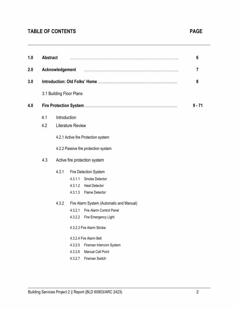
TABLE OF CONTENTS PAGE
1.0 Abstract …………………………………………………………………………. 6
2.0 Acknowledgement ……………………………………………………………….. 7
3.0 Introduction: Old Folks’ Home …………………………………………………….. 8
3.1 Building Floor Plans
4.0 Fire Protection System ………………………………………………………………. 9 - 71
4.1 Introduction
4.2 Literature Review
4.2.1 Active fire Protection system
4.2.2 Passive fire protection system
4.3 Active fire protection system
4.3.1 Fire Detection System
4.3.1.1 Smoke Detector
4.3.1.2 Heat Detector
4.3.1.3 Flame Detector
4.3.2 Fire Alarm System (Automatic and Manual)
4.3.2.1 Fire Alarm Control Panel
4.3.2.2 Fire Emergency Light
4.3.2.3 Fire Alarm Strobe
4.3.2.4 Fire Alarm Bell
4.3.2.5 Fireman Intercom System
4.3.2.6 Manual Call Point
4.3.2.7 Fireman Switch
Building Services Project 2 || Report (BLD 60903/ARC 2423) 3
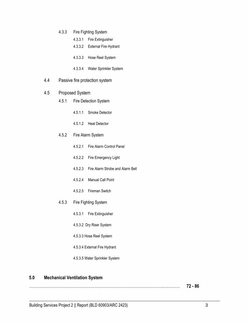
4.3.3 Fire Fighting System
4.3.3.1 Fire Extinguisher
4.3.3.2 External Fire Hydrant
4.3.3.3 Hose Reel System
4.3.3.4 Water Sprinkler System
4.4 Passive fire protection system
4.5 Proposed System
4.5.1 Fire Detection System
4.5.1.1 Smoke Detector
4.5.1.2 Heat Detector
4.5.2 Fire Alarm System
4.5.2.1 Fire Alarm Control Panel
4.5.2.2 Fire Emergency Light
4.5.2.3 Fire Alarm Strobe and Alarm Bell
4.5.2.4 Manual Call Point
4.5.2.5 Fireman Switch
4.5.3 Fire Fighting System
4.5.3.1 Fire Extinguisher
4.5.3.2 Dry Riser System
4.5.3.3 Hose Reel System
4.5.3.4 External Fire Hydrant
4.5.3.5 Water Sprinkler System
5.0 Mechanical Ventilation System
………………………………………………………………………………………..………… 72 - 86

Building Services Project 2 || Report (BLD 60903/ARC 2423) 4
5.1 Introduction
5.2 Literature Review
5.3 Specific System Selected
5.4 Types of Fan
5.4.1 Propeller Fan
5.4.2 Exhaust Hood
5.4.3 Centrifugal Fan
5.4.4 Ductwork
5.5 Proposed System
6.0 Air Conditioning System ……………………………………………………… 87 - 110
6.1 Introduction
6.2 Literature Review
6.3 Operating Principles of Air Cooling
6.3.1 Refrigeration Cycle
6.4 Types of Air Conditioning System
6.4.1 Window Air Conditioning System
6.4.2 Split Air Conditioning System
6.4.2.1 Outdoor Unit
6.4.2.2 Indoor Unit
6.4.3 Centralized Air Conditioning System
6.4.4 Packaged Air Conditioning System
6.5 Proposal of System
6.5.1 Analysis and Justifications
7.0 Mechanical Transportation System …………………………………………. 110 - 125
7.1 Introduction
7.2 Literature Review
7.2.1 Hydraulic Elevator
7.3 Standard Elevator Components
7.4 Operating Principles of Hydraulic Elevators
7.5 Safety System

Building Services Project 2 || Report (BLD 60903/ARC 2423) 5
7.6 Types of Elevator
7.6.1 Hydraulic Elevator
7.6.2 Traction Elevator
7.6.3 Machine-Room-Less(MRL) Elevator
7.7 Uniform Building By-Law & Other Requirements
8.0 Summary/ Conclusion…………………………………………….…………...…..… 126-127
9.0 References & Citation……………………………………………………………….. 128 -130

Building Services Project 2 || Report (BLD 60903/ARC 2423) 6
1.0 Abstract
In this assignment, we , as students are required to choose one of the group member’s design scheme from
Semester 4 Design Studio project which is Center for the Elderly. Each group is to perform a study and analysis of
the following services systems, and apply them in the proposal with appropriate justifications:
a. Mechanical ventilation
b. Air-conditioning system
c. Fire protection (active and passive fire protection system)
d. Mechanical transportation system (lift)
Throughout the assignment, we are able to explore and gain the knowledge from the building services systems.
Meanwhile, we can illustrate or apply our understanding into the proposed building, after the findings and analysis
that have been carried out. In-depth research through books and online resources has been done in order to create
precious and careful service system design. Regulations such as UBBL and Malaysian Standard are being applied
which align with building by-law which is important for us to understand the basic requirement of designing building
services.
Building Services Project 2 || Report (BLD 60903/ARC 2423) 7
2.0 Acknowledgement
Firstly, we would like to thank you Mr. Rizal for his guidance throughout the process of our project. Besides that, we
are also grateful that Mr. Rizal have spent his quality time with us. Helping us so much by providing some detailed
information during tutorial session. From this assignment, we have truly understand the functionality of using specific
system to ensure that the right system could be used on specific area. Finally, we would like to thank you all the
group members who put in so much effort and hard work into making the research report into a success.

Building Services Project 2 || Report (BLD 60903/ARC 2423) 8
3.0 Introduction: Old Folks’ Home
3.1 Building Floor

Building Services Project 2 || Report (BLD 60903/ARC 2423) 9
Plan

Building Services Project 2 || Report (BLD 60903/ARC 2423) 10

Building Services Project 2 || Report (BLD 60903/ARC 2423) 11
4.0 Fire Protection System
4.1 Introduction
Fire is the result of 3 major elements, which are fuel, oxygen and heat.
Fire Protection refers to the procedures and safety measures which is conducted to prevent or delay fire to be
destructive as well as reducing the impact of uncontrolled fire which could ensure the safety and property of people.
Fire protection is the study and practice of mitigating the unwanted effects of potentially destructive fires. It involves
the study of the suppression and investigation of fire and its related destructive fires. It involves the study of the
suppression and investigation of fire and its related emergencies, as well as the research and development,
production and testing. In structures, the owner and operators are responsible to maintain their facilities in
accordance with a design-basis that is rooted in laws, including the local building code that is in effect when an
application for a building permit is made. Building inspectors check on compliance of a building under construction
with the building code. Once construction is complete, a building must be maintained in accordance with the building
code. Once construction is complete, a building must be maintained in accordance with the current fire code, which is
enforced by the fire prevention officers of a local fire department. In the event of fire emergencies, firefighters, fire
investigators, and other fire prevention personnel called to mitigate, investigate and learn from the damage of a
fire.The purpose of fire protection is to prevent building occupants, properties from the damage which resulted by fire.
It aims to avoid the fire spread from one building to another. There are 2 types of fire protections that can be carried
out, which are active fire protection system and passive fire protection system.
4.2 Literature Review

Building Services Project 2 || Report (BLD 60903/ARC 2423) 12
4.2.1 Active fire protection system
Active Fire Protection (AFP) is a group of systems that require some amount of action or motion in order to work
efficiently in the event of a fire. Actions may be manually operated, like a fire extinguisher or automatic, like a
sprinkler, but either way they require some amount of action. The system targets to detect the early stage of fire
before it grows bigger, and notify or give emergency warning to building occupants, so that they can escape and
extinguish the fire before it’s too late. Active fire protection systems are separated into 3 stages, Fire detection, Fire
notification, and Fire fighting (Water based system and Non-water based system).
4.2.2 Passive fire protection system
By law, every building needs to have passive fire protection. It is to provide safety for the users during an evacuation
of fire. An effective passive fire protection can be done on a building by considering the users of the building, the
function of the building, the height of the building and the type of the building. Users should be protected within the
building during evacuation. Generally, the idea to escape the building is to provide escape route, emergency access,
uses of materials that have high fire resistant and not depending on the operation of mechanical device.
A safe escape route is needed to provide safe surroundings for user to be able to leave the building and gather at the
assembly point safely, hence escape route need to be kept clear from obstructions, so that there is a clear path for
user, in order to keep it clear, some areas are suggested to be emergency access. Besides, most of the time the
escape routes are normally located at areas which less likely to be the starting point of fire. Some building include
smoke chamber before entering the escape routes, normally windows are placed in this chamber to filter out the
smoke but some do it mechanically. Escape routes are also well ventilated with windows or mechanically , this is to
ensure sufficiency of oxygen within the routes. Never the less, the materials that are used need to be fire resistance
materials, it is buy time for the users to leave the building, to prevent the spreading of fire towards the escape routes.
4.3 Active fire protection system
4.3.1 Detection
Automatic fire detection systems detect the initial stage of fire and notify the building occupants to leave or take
action by giving emergency responses. This will significantly reduce property damage, personal injuries, even loss of

Building Services Project 2 || Report (BLD 60903/ARC 2423) 13
life from the fire. This system can use electronic sensors to detect the presence of fire resulting elements such as
smoke, heat and flames.
According to UBBL 1984 Section 225:
Every building shall be provided with means of detecting and extinguishing fire and with fire alarms together with
illuminated exit signs in accordance with the requirements as specified in the Tenth Schedule to these By-laws.
4.3.1.1 Smoke dectector
There are two main smoke alarms generally used in the industry, which are ionization detectors and photoelectric
detectors. Below is the table that showing the comparison of 2 types of smoke detectors.
Ionization smoke detector
Comparison aspects
Photoelectric smoke detector
Contain a very small amount of
americium-241 within an ionization
chamber. They create an electric
current between two metal plates,
which sound an alarm when
disrupted by smoke entering the
Principles
Contain a light source in a light-
sensitive electric sensor, which are
positioned at 90-degree angles to
one another. Normally, light from the
light source shoots straight across
and misses the sensor. When
smoke enters the chamber, it

Building Services Project 2 || Report (BLD 60903/ARC 2423) 14
chamber. scatters the light, which then hits the
sensor and triggers the alarm.
Faster to flaming fire (growth stage) Respond Faster to a smoldering fire (early
stage)
Contains radioactive material,
Americium-241
Environment Eco-friendly
Frequent (30% disconnected) False alarm Few (Approximately 8 times lesser)
High (56% failure for smoldering
fire, 20% failure for flaming fire)
Failure rate Low (4% failure for both smoldering
and flaming fire)
Cheap Price Expensive
4.3.1.2 Heat detector
Heat detector is used to detect the heat, where the alarm contains a thermistor (sensor) to respond to temperatures
above 58 Celsius. This detector is suitable for spaces such as kitchen and garage, as the heat alarms don’t react to
smokes, which means they are not prone to false alarms from cooking or exhaust fumes. Below are the illustrations
that shows how the heat detector works:
Stage 1. Hot air from the fire will rise and enter the sensor chamber of the detector.
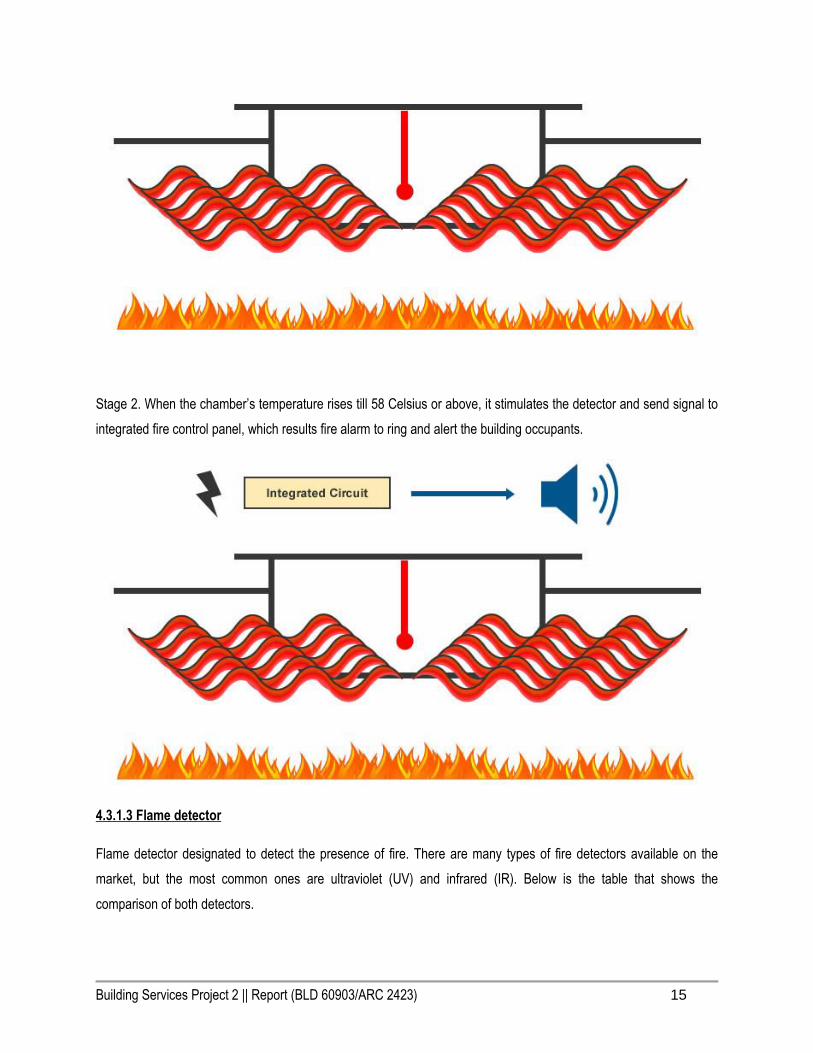
Building Services Project 2 || Report (BLD 60903/ARC 2423) 15
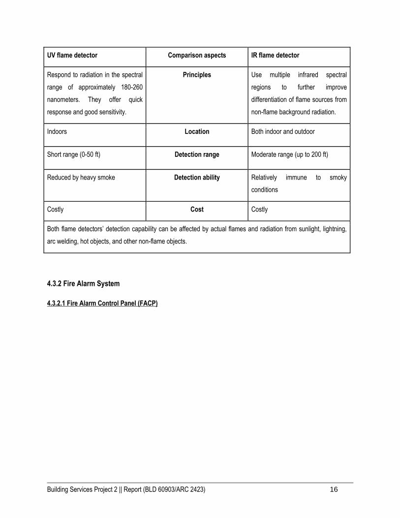
Stage 2. When the chamber’s temperature rises till 58 Celsius or above, it stimulates the detector and send signal to
integrated fire control panel, which results fire alarm to ring and alert the building occupants.
4.3.1.3 Flame detector
Flame detector designated to detect the presence of fire. There are many types of fire detectors available on the
market, but the most common ones are ultraviolet (UV) and infrared (IR). Below is the table that shows the
comparison of both detectors.
Building Services Project 2 || Report (BLD 60903/ARC 2423) 16
UV flame detector Comparison aspects IR flame detector
Respond to radiation in the spectral
range of approximately 180-260
nanometers. They offer quick
response and good sensitivity.
Principles Use multiple infrared spectral
regions to further improve
differentiation of flame sources from
non-flame background radiation.
Indoors Location Both indoor and outdoor
Short range (0-50 ft) Detection range Moderate range (up to 200 ft)
Reduced by heavy smoke Detection ability Relatively immune to smoky
conditions
Costly Cost Costly
Both flame detectors’ detection capability can be affected by actual flames and radiation from sunlight, lightning,
arc welding, hot objects, and other non-flame objects.
4.3.2 Fire Alarm System
4.3.2.1 Fire Alarm Control Panel (FACP)

Building Services Project 2 || Report (BLD 60903/ARC 2423) 17
Fire alarm system is important in active fire protection system as its role in alerting or delivering emergency signals to
building occupants to take action as soon as possible. Usually the system can be done automatically or manual.
Automatic fire alarm system is connected with detectors (smoke,heat,flame detector) as initial sign of fire, then
trigger the fire alarm system (strobe, alarm bell) to be operated and eventually fire fighting(water sprinkler system)
will be carried out. Whereas manual fire alarm system will be started from manual pull station and fire intercom
system, which require user to operate to trigger the fire alarm and fighting system. Usually two-stage fire alarm
system being used which designated for building staff only. The staff are expected to investigate the source of the
alarm, and activate the alarm signal if the fire exists. The alarm signal is automatically set off after a predetermined
period of time if the staff have not already activated it or reset the alarm system. Staff can silent the coded alert signal
and reset the system if the alert is determined as a false alarm. Generally, there are two types of fire alarm system,
which are conventional fire alarm system and addressable fire alarm system. Below are the comparison of both
systems:
Conventional fire alarm system
Comparison aspects
Addressable fire alarm system
With a conventional system, there is Principles Every device connected to the

Building Services Project 2 || Report (BLD 60903/ARC 2423) 18
no way of pinpointing the exact
location of the fire. However, by
wiring your building into different
zones, you can get a general idea of
where the fire is. For instance, if you
have two floors, you could wire the
first as ‘zone 1’ and the second as
zone 2.
addressable system has its own
unique address. When a fire is
detected, the device’s address
shows up on the main control panel,
telling you exactly which device has
been activated. This will enable you
to find the exact location of a fire
and extinguish them quickly.
With a conventional alarm, each
device will be connected to the
control panel via its own wire, rather
than a shared one. One end of the
wire will be touching the device, and
another touching the control panel.
Wiring difference Addressable alarm systems connect
devices using a loop. This is where
one wire connects all devices to the
control panel. Both ends of the wire
loop connect to the control panel.
Cheaper to buy but expensive
installation cost
Price Optional, can be costly depends on
the user
If a wire has become severed, the
device will become disconnected.
Preference Reliable because the wire connects
to the control panel at both ends. If
one end of the loop becomes
severed, signals can still be sent to
the control panel via the other end of
the loop. Loop isolation modules are
also used to separate devices on
the loop. This means that if one
device becomes disconnected, it
won’t disable the circuit.
4.3.2.2 Fire Emergency Light

Building Services Project 2 || Report (BLD 60903/ARC 2423) 19
Fire emergency lighting is the lighting that provided for an emergency situation where the main power supply is cut as
well as the normal illumination fails. It operates automatically and give sufficient light to enable building occupants to
evacuate the premises safely. There are 2 types of power supply that connected to emergency light so that it can be
function by the time required, which are self-contained (single point) and central battery source. Below are the
comparison between both types of emergency light:
Self-contained Comparison aspects Central battery source
-Faster and cheaper to install
-Standard wiring material provided
-Low maintenance and hardware
equipment cost
-Each luminaire is independent of
the others
-Easily extended with additional
luminaires
-No special sub-circuit monitoring
requirement
Advantages -Easy maintenance and routine
testing
-Average battery life is 5 to 25 years
-Environmentally stable
-Can operate at high or low ambient
temperature
-May be adversely affected by a
relatively high or low ambient
Disadvantages -High capital equipment costs
-Cost of installation and wiring

Building Services Project 2 || Report (BLD 60903/ARC 2423) 20
temperature
-Battery life is limited between 2 to 4
years
-Testing requires isolation and
observation of luminaires on an
individual basis
system is high
-Poor system integrity whereas the
failure of battery can disable a large
part of the system
-Localised mains failure may not
trigger operation of emergency
lighting
-Voltage can be drop depends on
the distance from the central battery
Typically, self-contained luminaire
becomes most popular choice due
to the cost from installation and
material
Preference
4.3.2.3 Fire Alarm Strobe
Strobe light is designated to deliver cost-efficient installation time. Usually this light will be provided along with alarm
bell, to produce visual-audio system to alert the occupants during the fire. There are few choices available in the
market, but the most common colors that can be found are red and white. Voltages that usually involved in the
operation of this device are 12 or 24 volt. It provides light by giving 1 or 2 flashes per second, which creates greater
attention compared to constant lighting.
4.3.2.4 Fire Alarm Bell

Building Services Project 2 || Report (BLD 60903/ARC 2423) 21
Fire alarm bell is the device that delivers high pressure sound pressure output that gives warning to occupants during
the fire. Most of the fire alarm bell makes sounds like a siren but alternating frequencies. It is available for 120 volt
(AC) or 24 volt (DC), which offered in variable sizes, such as 6,8, and 10 inches. Usually it is painted in red color so
that can be noticed from far.
4.3.2.5 Fireman Intercom System
Fireman Intercom System provides a direct communication between master fire control room and remote handset
station. Master fire control room has the All remote handset have continuous supervision for any faulty with fast
check and maintenance. Usually remote handset station located at the fire escape staircase. There is only one button
on the it which is easy for all to understand the operation way. Fire control room only required for building with height
of more than 25 metres or 18000 metres square in floor area.
4.3.2.6 Manual Call Point

Building Services Project 2 || Report (BLD 60903/ARC 2423) 22
Manual alarm call points are designed for the purpose of raising an alarm manually once verification of a fire or
emergency condition exists, by operating the push button or break glass the alarm signal can be raised.
4.3.2.7 Fireman Switch
Fireman switch is a switch that disconnects the power supply of electrical equipments in case of fire to
prevent overheated equipment from exploding. It is usually located on the outside wall of premises.
4.3.3 Fire Fighting System
After the process of detection and notification system, the action should be taken to stop the fire from spreading or
growing into bigger threats for a building or neighbouring building. There are 2 basic types of system that can be
applied to control the fire, which are water-based system and non water-based system. Basically water-based system
used water as the main element to extinguish the fire, while non-water based system used other content to stop the
Building Services Project 2 || Report (BLD 60903/ARC 2423) 23
fire, such as Carbon Dioxide, Argonite etc. Table below shows some examples of water-based and non-water based
system
Water-based system Non water-based system
Fire Extinguisher (Water) Fire Extinguisher (Dry powder, Carbon Dioxide)
External Fire Hydrant
Dry Riser System
Hose Reel System
Water Sprinkler system
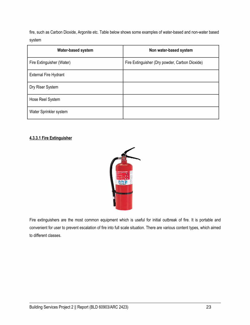
4.3.3.1 Fire Extinguisher
Fire extinguishers are the most common equipment which is useful for initial outbreak of fire. It is portable and
convenient for user to prevent escalation of fire into full scale situation. There are various content types, which aimed
to different classes.

Building Services Project 2 || Report (BLD 60903/ARC 2423) 24
According to UBBL 1984 Section 244:
All fire fighting installations and appliances shall conform to the current edition of the following standards:
C. Portable Extinguishers... BS CP 402 Part 3: 1964
UBBL 1984 Section 227:
Portable extinguisher shall be provided in accordance with the relevant codes of practice and shall be sited in
prominent positions on exit routes to be visible from all directions and similar extinguishers in a building shall be of
the same method of operations.
MS 1539: Specification for Portable Fire Extinguishers
Part 1: Construction & Test Methodology
Part 3: Selection & Application - Code of Practice
Part 4: Maintenance of Portable Fire Extinguishers
4.3.3.2 External Fire Hydrant
Building Services Project 2 || Report (BLD 60903/ARC 2423) 25
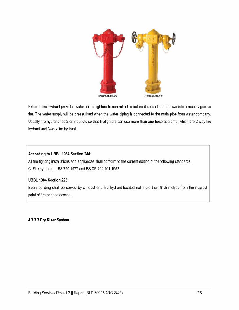
External fire hydrant provides water for firefighters to control a fire before it spreads and grows into a much vigorous
fire. The water supply will be pressurised when the water piping is connected to the main pipe from water company.
Usually fire hydrant has 2 or 3 outlets so that firefighters can use more than one hose at a time, which are 2-way fire
hydrant and 3-way fire hydrant.
According to UBBL 1984 Section 244:
All fire fighting installations and appliances shall conform to the current edition of the following standards:
C. Fire hydrants… BS 750:1977 and BS CP 402.101;1952
UBBL 1984 Section 225:
Every building shall be served by at least one fire hydrant located not more than 91.5 metres from the nearest
point of fire brigade access.
4.3.3.3 Dry Riser System

Building Services Project 2 || Report (BLD 60903/ARC 2423) 26
Dry riser are a form of internal hydrant for firefighter to use. This system is only required for buildings which the
topmost floor is higher than 18.3 metres and less than 30.5 metres above the fire appliance access level. Wet riser
system has the same function as dry riser system, but it is always dry and depends on the fire engine to pump the
water into the system.
According to UBBL 1984 Section 230 :
1. Dry rising systems shall be provided in every building in which the topmost floor is more than 18.3 metres
but less than 30.5 metres above fire appliance access level.
2. A hose connection shall be provided in each fire fighting access lobby.
3. Dry risers shall be of minimum Class C pipes with fittings and connections of sufficient strength to
withstand 21 bars water pressure.
4. Dry risers shall be tested hydrostatically to withstand not less than 14 bars of pressure for 2 hours in the
presence of the Fire Authority before acceptance.
5. All horizontal runs of the dry rising systems shall be pitched at the rate of 6.35 mm in 3.05 metres.
6. The dry riser shall be not less than 102mm in diameter in buildings in which the highest outlet is 22.875
metres or less above the fire brigade pumping inlets and not less than 152.4mm diameter where the
highest outlet is higher than 22.875 metres above the pumping inlet.
7. 102mm diameters dry riser shall be equipped with a two-way pumping inlet and 152.4mm dry risers shall
be equipped with a four-way pumping inlet.
UBBL 1984 Section 244:
All fire fighting installations and appliances shall conform to the current edition of the following standards:
D. Dry/Wet Rising Mains… BS 3980:1966 and BS 5306 Part 1:1976 and BS 750: 1964

Building Services Project 2 || Report (BLD 60903/ARC 2423) 27
Landing valve should be provided as the water outlet which will connected with a hose reel to control and fight the
fire.
4.3.3.4 Hose Reel System
Fire hose reel systems consist of pumps, pipes, water supply and hose reels located strategically in a building,
ensuring proper coverage of water to combat a fire.The system is manually operated and activated by opening a
valve enabling the water to flow into the hose that is typically 30 meters away. It should be located at strategic places
in building to provide reasonable accessible and controlled supply of water for fire extinguishing. Table below shows
the comparison of materials of hose reels:
Rubber jacket fire hose reel Comparison aspects Woven jacket fire hose reel
-Heavy
-Durable
Properties -Available in nylon and polyester
-Nylon (strong and abrasion-
resistant)
-Polyester (durable and budget-
friendly)
-Yarn weave - Rubber canvas PVC
(flexible and stiff and light)
Building Services Project 2 || Report (BLD 60903/ARC 2423) 28
According to UBBL 1984 Section 244:
1. All fire fighting installations and appliances shall conform to the current edition of the following
standards:
B. Hydraulic Hose Reels… BS 5306 Part 1: 1976
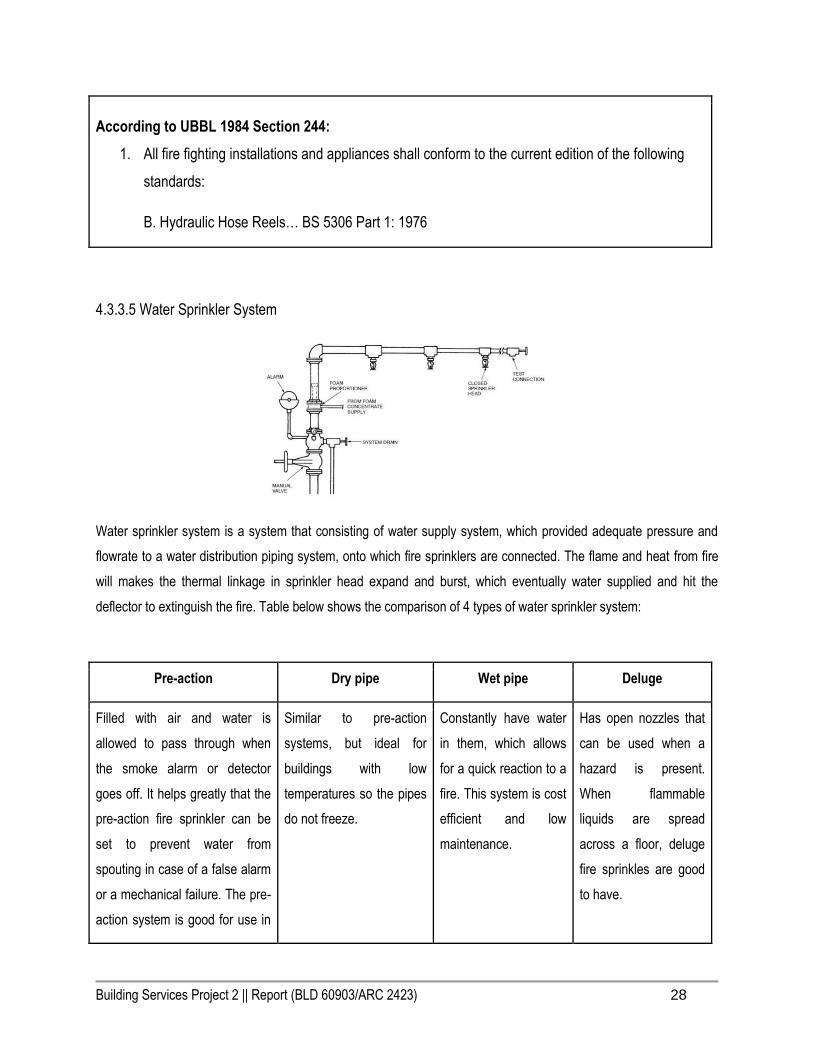
4.3.3.5 Water Sprinkler System
Water sprinkler system is a system that consisting of water supply system, which provided adequate pressure and
flowrate to a water distribution piping system, onto which fire sprinklers are connected. The flame and heat from fire
will makes the thermal linkage in sprinkler head expand and burst, which eventually water supplied and hit the
deflector to extinguish the fire. Table below shows the comparison of 4 types of water sprinkler system:
Pre-action Dry pipe Wet pipe Deluge
Filled with air and water is
allowed to pass through when
the smoke alarm or detector
goes off. It helps greatly that the
pre-action fire sprinkler can be
set to prevent water from
spouting in case of a false alarm
or a mechanical failure. The pre-
action system is good for use in
Similar to pre-action
systems, but ideal for
buildings with low
temperatures so the pipes
do not freeze.
Constantly have water
in them, which allows
for a quick reaction to a
fire. This system is cost
efficient and low
maintenance.
Has open nozzles that
can be used when a
hazard is present.
When flammable
liquids are spread
across a floor, deluge
fire sprinkles are good
to have.

Building Services Project 2 || Report (BLD 60903/ARC 2423) 29
places where the sprinklers are
only necessary when there is an
actual fire so other items in the
building do not get water
damage from an accidental
sprinkling.
According to UBBL 1984 Section 244:
1. All fire fighting installations and appliances shall conform to the current edition of the following standards:
F. Automatic Sprinklers...FOC Rules 29th Edition:1973
UBBL 1984 Section 226:
1. Where hazardous processes, storage or occupancy are of such character as to require automatic
sprinklers or other automatic extinguishing system, it shall be of a type and standard appropriate to
extinguish fires in the hazardous materials stored or handled or for the safety of the occupants.
UBBL 1984 Section 228:
1. Sprinklers valves shall be provided in a safe and enclosed position on the exterior wall and shall be
readily accessible to the Fire Authority.

Building Services Project 2 || Report (BLD 60903/ARC 2423) 30
2. All sprinkler systems shall be electricity connected to the nearest fire station to provide immediate and
automatic relay of the alarm when activitated
4.4 Passive Fire Protection System
Passive Fire Protection (PFP)
Passive Fire protection is part of integral elements of structural fire protection as well as fire safety in every particular
building which does not depend on any operating system of mechanism or any degree of motion. However, PFP itself
shows the speed on spreading of fire from a space to another space where only effective for 2 hours to allow dweller
to escape form fire menace bu using fire protection tolls that is provided for the building. Passive Fire Protection
system is provided on the load bearing capacity of the fire exposed structure in a specified fire compartment, safety
escape, fire separation within the building stability that needs to be concerned.
Main Passive Fire Protection Methods
(1) Cavity Barriers – Prevent spread of smoke and fire through walls and floors
(2) Instrumental Coating – Increase in temperature cause chemical reaction ( coating expand ) to protect steel work
by insulating the steel ( prevent structural failure)
(3) Boarding Systems – Encasing structural steel work in rigid and semi-rigid boards
(4) Fire Resistant Glass – Heat insulating material that halts the spread of fire and window blows out
Building Materials (Duration of time in flame )
(1) Red brick wall and concrete (external wall) : 4 hours
(2) Light brick wall (internal wall) – minimum 1 hour
Building Services Project 2 || Report (BLD 60903/ARC 2423) 31
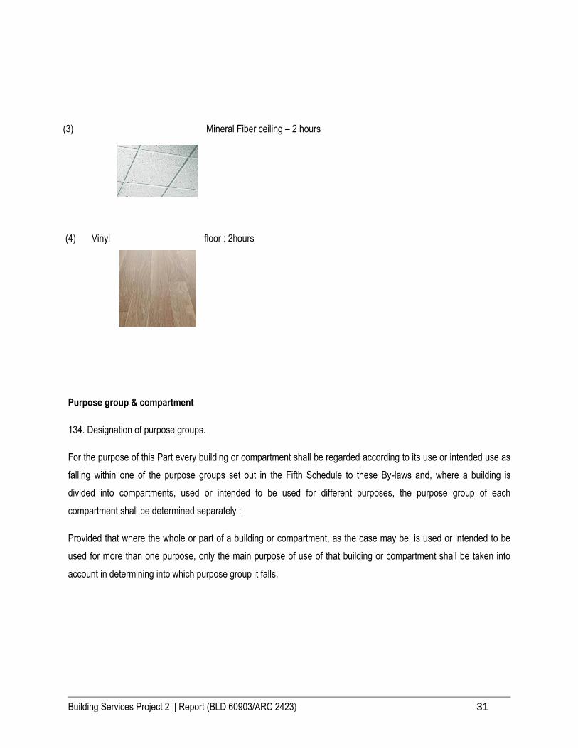
(3) Mineral Fiber ceiling – 2 hours
(4) Vinyl floor : 2hours
Purpose group & compartment
134. Designation of purpose groups.
For the purpose of this Part every building or compartment shall be regarded according to its use or intended use as
falling within one of the purpose groups set out in the Fifth Schedule to these By-laws and, where a building is
divided into compartments, used or intended to be used for different purposes, the purpose group of each
compartment shall be determined separately :
Provided that where the whole or part of a building or compartment, as the case may be, is used or intended to be
used for more than one purpose, only the main purpose of use of that building or compartment shall be taken into
account in determining into which purpose group it falls.

Building Services Project 2 || Report (BLD 60903/ARC 2423) 32
The walls that are indicated red are compartment walls. Walls that are located at walkway/ corridor are proposed as
compartment walls as they help to prevent fire spread towards the corridor and other spaces.
According to UBBL : 136. Provision of compartment walls and compartment floors.
Any building, other than a single storey building, of a purpose group specified in the Fifth Schedule to these By-
laws and which has –
(a) any storey the floor area of which exceeds that specified as relevant to a building of that purpose group and
height ; or
(b) a cubic capacity which exceeds that specified as so relevant shall be so divided into compartments, by means
of compartment walls or compartment floors or both, that –
(i) no such compartment has any storey the floor area of which exceeds the area specified as
relevant to that building ; and
(ii) no such compartment has a cubic capacity which exceeds that specified as so relevant to the
building :

Building Services Project 2 || Report (BLD 60903/ARC 2423) 33
Provided that if any building is provided with an automatic sprinkler installation which complies with the relevant
recommendations if the F.O.C Rules for Automatic Sprinkler Installation, 29th edition, this by-law has effect in
relation to that building as if the limits of dimensions specified are doubled.
Walls and floor
According to UBBL: 136: Any building, other than a single storey building, of a purpose group specified in
the Fifth Schedule to these By-laws and which has-
(a) Any storey the floor area of which exceeds that specified as relevant to a building of that purpose group and
height :
(b) A cubic capacity which exceeds that specified as so relevant shall be so divided into compartment floors or
both, that-
i) No such compartment has any storey the floor area of which exceeds the area specified as
relevant to that building ; and
ii) No such compartment has cubic capacity which exceeds the area specified as relevant to
that building :
Provided that if any building is provided with an automatic sprinkler installation which complies with the relevant
recommendations of the F.O.C Rules for Automatic Sprinkler Installation, 29th edition, this by-law has effect in
relation to that building as if the limits of dimensions specified are doubled.
138. The following walls and floors in buildings shall be constructed as compartment walls or compartment floors :
(a) Any floor in a building of Purpose Group II (Institutional) ;
(b) Any wall or floor separating a flat or maisonette from any other part of the same building;
(c) Any wall or floor separating part of a building from any other part of the same building which is used or intended
to be used mainly for a purpose falling within a different purpose group as set out in the Fifth Schedule to these
By-laws; and
Building Services Project 2 || Report (BLD 60903/ARC 2423) 34
(d) Any floor immediately over a basement storey has an area exceeding 100 square meters.
162. Fire rated doors
(1) Fire doors of the appropriate FRP shall be provided.
(2) Openings in compartment walls and separating walls shall be protected by a fire door having a FRP in
accordance with the requirements for that wall specified in the Ninth Schedule to these By-laws.
(3) Openings in protecting structures shall be protected by fire doors having FRP of not less than half the
requirement for the surrounding wall specified in the Ninth Schedule to these By-laws but in no case less than half
hour.
(4) Openings in partition enclosing a protected corridor or lobby shall protected by fire doors having FRP of half-
hour.
(5) Fire doors including frames shall be constructed to a specification which can be shown to meet the
requirements for relevant FRP when tested in accordance with section 3 of BS 476:1951.
163:
Fire doors conforming to the method of construction as stipulated below shall be deemed to meet the requirements
of the specified FRP :
a) Doors and frames constructed in accordance with one of the following specifications shall be deemed to satisfy
the requirements for doors having FRP of half-hour:
(i) a single door 900 millimeters high maximum of double doors 1800 millimeters x 2100
millimeters high maximum constructed of solid hardwood core of not less than 37 millimeters
laminated with adhesives conforming to either BS.745 “Animal Glue”, or BS1204, “Synthetic
resin adhesives (phenolic and aminoplastic ) for wood” Part I, “Gap-filling adhesives”, or BS
1444, “Cold-setting casein glue for wood”, faced both sides with plywood to a total thickness of
not less than 43 millimeters with all edges finished with a solid edge strip full width of the door.
The meeting stiles of double doors shall be rabbeted 12 millimeters deep or may be butted
provided the clearance is kept to a minimum;
(ii) doors may be double swing provided they are mounted on hydraulic floor springs and
clearances at floor not exceeding 4.7 millimeters and frame and meeting stiles not exceeding 3

Building Services Project 2 || Report (BLD 60903/ARC 2423) 35
millimeters;
(iii) a vision panel may be incorporated provided it does not exceed 0.065 square meter per leaf
with no dimension more than 1370 millimeters and it is glazed within 6 millimeters Georgian
Wired Glass in Hardwood stops;
(iv) doors constructed is accordance with BS No. 459 : Part 3 : 1951 Fire Check Flush Doors and
Wood and Metal frames ( Half –Hour Type) :
(v) timber frames for single swing half-hour fire doors of overall width of 60 millimeters including
25 millimeters rabbet and depth to suit door thickness plus 34 millimeters stop;
(vi) metal frames for half hour fire doors shall be of sheet steel not lighter than 18 gauge of overall
width 50 millimeters including 18 millimeters rabbet and depth to suit the door thickness plus 53
millimeters stop;
(vii) timber or metal frames for double swing doors shall be as specified above with minimum
clearance between frame and door;
(a) Door and frames constructed in accordance with one of the following specifications shall be deemed to satisfy the
requirements for door having FRP of one hour:
(i) a single door not exceeding 900 millimeters wide x 2100 millimeters high or double doors
not exceeding 1800 millimeters x 2100 millimeters high constructed as for specification (a) for
half-hour but incorporating on both faces a layer of asbestos insulating board to BS 3536 (not
asbestos cement) not less than 3 millimeters thick;
(ii) doors may swing one way only and double doors shall have 12 millimeters wide rabbet at the
meeting stiles;
(iii) a vision panel may be incorporated provided it does not exceed 10 square meters per leaf
with no dimension more than 300 millimeters and it is glazed with 6 millimeters Georgian Wire
Glass in hardwood stop;
(iv) doors constructed in accordance with BS 459 : Part 3 : 1951 : Fire Check Flush Doors and
Wood and Metal frames (One Hour Type) ;
(v) frames for one hour doors shall be as for half-hour door except that timber frames shall

Building Services Project 2 || Report (BLD 60903/ARC 2423) 36
pressure impregnated with 15% go 18% solution of monoammonium phosphate in water.
164 : (1) All the fire doors shall be fitted with automatic door closers of hydraulically spring operated type in the
case of swing doors and of wire rope and weight type in the case of sliding doors.
(2) Double doors with rabbeted meeting stiles shall be provided with coordinating device to ensure that leafs close
in the proper sequence.
(3) Fire doors may be held open provided the hold open device incorporates a heat actuated device to release the
door. Heat actuated devices shall not be permitted on fire doors protecting openings to protected corridors or
protected staircases.
86. Party walls
(1) All party walls shall generally be of not less than 200mm total thickness of solid masonry or insitu concrete
which may be made up of two separate skins each of not less than 100mm thickness if constructed at different
times :
Provided that in multi-storeyed flats and terrace houses of reinforced concrete or of protected steel framed
construction having floors and roofs constructed to the requirements of these By-laws, the party wall thereof shall
not less than 100mm total thickness.
(2) Party walls in single storeyed houses may be in load-bearing 100mm solid masonry or insitu concrete provided
the requirements of Part V, VI and VII of these By-laws are complied with.
(3) All party walls shall be carried above the upper surface of the roof to a distance of not less than 230mm at night
angles to such upper surface.
(4) Other non-combustible materials may be used for party walls provided the requirements of Part V, VI and VII of
these By-laws are complied with.
Analysis :

Building Services Project 2 || Report (BLD 60903/ARC 2423) 37
As passive fire protection is a planning matter and must be considered at the planning stage in the building design in
order to allocate fire risk area away from the building spaces. An effective passive fire protection shows good
planning and good design. As prevention is better than cure, it is better to prevent fire from spreading into the
building than having to put out the fire. Hence, material choice are all fire rated to slow down the spreading of fire.
Ground floor plan , first floor plan and second floor plan with fire staircases marked red.
As shown in the plans above, those are the location of the fire staircases. The position of the stairs are the same
from Ground floor all the way up to the second floor. Fire staircase allows the users of the building to evacuate from
the building to assembly point during fire or any emergency event happen. The width of staircase maintains same all
over the way of staircase till the exit. The width of staircase (1200mm) suggests one user at a time. The height of
riser 170mm and the thread is 255mm. Handrail with a height of 900mm is used for safety purpose of the users of the
staircase.

Building Services Project 2 || Report (BLD 60903/ARC 2423) 38
Smoke control
194. Building with single staircase .
A single staircase may be permitted in any building the top most floor of which does not exceed 12 metres in
height :
Provided that such building complies with the following condition :
(a) each element of structure shall have a FRP of not less than one hour ;
(b) no room or storey of the building may be used for any occupancy other than for domestic or office purposes,
except that the ground storey may be used for the purpose of a shop or car park :
Provided that-
(i) the staircase from the ground to first floor level shall be separated from the remainder of the
ground floor by a wall having a FRP of not less than two hours ;
(ii) the wall enclosing the staircase at the main entrance be returned for a distance of not less than
450mm along the frontage of any shop or car park ;
(iii) the maximum travel distance shall be 12m measured from the door of the room or area to the exit
provided the path of travel from any point in the room to the room door does not exceed 12 meters.
(iv) In ground and first storeys which have windows containing opening lights sufficiently near the
adjacent ground level as to make emergency escape by this means reasonable a maximum travel
distance up to 30 meters is permissible.
195. Staircases to reach roof level.
In buildings exceeding 30 metres in height all staircases intended to be used as means of egress shall be carried
to the roof level to give access thereto.

Building Services Project 2 || Report (BLD 60903/ARC 2423) 39
Protected areas : Protection of stairs and lobbies
UBBL:
196. (1) Access to a staircase smoke lobby shall be by means of fire doors opening in the direction of escape.
(2) The width of the smoke lobby shall at no point be less than the required exit width.
(3) Smoke lobbies shall be provided at the basement levels where an escape staircase serving an upper storey is
extended to a basement.
(4) Where practical smoke lobbies and fire fighting access lobbies shall have permanent openings or openable
windows of not less than 1 square metre giving direct access to the open air from an external wall or internal light
well.
(5) Where natural ventilation is impractical smoke lobbies and fire fighting access lobbies maybe be ventilated by
means of a vertical shaft or mechanically pressurised.
197. (1) Protected lobbies shall be provided to serve staircases in buildings exceeding 18 metres above ground
level where the staircase enclosures are not ventilated through external walls.
(2) In buildings exceeding 45 metres above ground level, such protected lobbies shall be pressurised to meet the
requirements of Section 7 of the Australian Standard 1668, Part I – 1974 or any other system meeting the
functional requirements of the D.G.F.S.
(3) Protected lobbies may be omitted if the staircase enclosures are pressurised to meet the requirements of by-
law 200.
Building Services Project 2 || Report (BLD 60903/ARC 2423) 40
Ventilation of stairs
198. (1) All staircase enclosures shall be ventilated at each floor or landing level by either permanent openings or
openable windows to the open air having a free area of not less than 1 square metre per floor.
(2) Openable windows shall meet the operational requirements of the D.G.F.S.
(3) In buildings not exceeding three storeys above ground level, staircase enclosures may be unventilated
provided that access to them at all levels except the top floor is through ventilated lobbies.
199. In buildings not exceeding 18 metres above ground level, staircase enclosures may be unventilated provided
that access to them at all levels except the top floor is through ventilated lobbies and the staircase enclosures are
permanently ventilated at the top with at least 5% of the area of the enclosures.
200. For staircases in building exceeding 18 metres above ground level that are not ventilated in accordance with
by-law 198, two alternative methods of preventing the infiltration of smoke into the staircase enclosures may be
permitted by providing –
(a) permanent ventilation at the top of the staircase enclosure of not less than 5% of the area of the enclosure and
in addition at suitable intervals in the height of the staircase a mechanically ventilated shaft to achieve not less
than 20 air changes per hour to be automatically activated by a signal from the fire alarm panel; or
(b) mechanical pressurisation of the staircase enclosure to the standard of performance as specified in section 7 of
the Australian Standard 1668, Part I-1974 or any other system meeting the functional requirements of the D.G.F.S.
201. All staircase enclosures below ground level shall be provided with suitable means of preventing the ingress of
smoke.

Building Services Project 2 || Report (BLD 60903/ARC 2423) 41
The yellow area is the assembly point, the red
arrows indicate pathways to the assembly point from the fire staircases.
As shown above ( ground floor plan ) , the assembly point is located at an open space right outside the hospital.
Each staircase is provided with more than one route to reach the assembly point just in case some routes are
blocked. The assembly point is normally classified with different class according to the capacity of users, for a day
care center for the elderly, it is classified as Class C because it has less than 100 to 300 users in this building,
Assembly Point

Building Services Project 2 || Report (BLD 60903/ARC 2423) 42
According to UBBL:
178. In buildings classified as institutional or places of assembly, exits to a street or large open space, together
with staircases, corridors and passages leading to such exits shall be located, separated or protected as to avoid
any undue danger to the occupants of the place of assembly from fire originating in the other occupancy or smoke
therefrom.
179 : Each place of assembly shall be classified according to its capacity as follows :
Class A-Capacity- 1000 persons or more
Class B- Capacity- 300 to 1000 persons
Class C- Capacity- 100 to 300 persons
180: The occupancy load permitted in any place of assembly shall be determined by dividing the net floor area or
space assigned to use by the square metre per occupant as follows :
(a) Assembly area of concentrated use without fixed seats such as an auditorium, places of worship, dance floor and
lodge room- 0.65 square per person :
(b) Assembly area of less concentrated use such as a conference room, dining room, drinking establishment , exhibit
room, gymnasium, or lounge – 1.35 square metre per person;
(c) Standing room or waiting space – 3 square metres per person :
(d) The occupancy load of an area having fixed seats shall be determined by the number of fixed seats installed.
Required aisle space serving the fixed seats shall not be used to increase the occupants load.
188. Exits in any place of assembly shall be arranged that the travel distance from any point to reach an exit shall
not exceed 45 metres for unsprinkled buildings and 60 metres for sprinkled buildings.
Travel Distance
According to UBBL :
165. (1) The travel distance to an exit shall be measured on the floor or other walking surface along the centre line

Building Services Project 2 || Report (BLD 60903/ARC 2423) 43
of the natural path of travel, starting 0.300 metre from the most remote point of occupancy, curving around any
corners or obstructions with 0.300 metre clearance the reform and ending at the storey exit. Where measurement
includes stairs, it shall be taken in the place of the trend noising.
(2) In the case of open areas the distance to exits shall be measured from the most remote point of occupancy
provided that the direct distance shall not exceed two- third the permitted travel distance.
(3) In the case of individual rooms which are subject to occupancy of not more than six persons, travel distance
shall be measured from the doors of such rooms: provided that the travel distance from any point in the room to
the room door does not exceed 15 metres.
(4) The maximum travel distances to exits and dead end limits shall be as specified in the Seventh Schedule of
these By-laws.
166. (1) Except as permitted by by-law 167 not less than two separate exits shall be provided from each storey
together with such additional exits as may be necessary.
(2) The exits shall be so sited within the limits of travel distance as specified in the Seventh Schedule to these By-
laws and are readily accessible at all times.
168: (1) Except as provide for in by-laws 194 every upper floor shall have means of egress via at least two
separate staircases.
(2) Staircase shall be of such width that in the event of any one staircase not available for escape purpose the
remaining staircase shall accommodate the highest occupancy load of any one floor discharging into it calculated
in accordance with provisions in the Seventh Schedule to these By-laws.
(3) The required width of a staircase shall be clear width between walls but handrails may be permitted to
encroach on this width to a maximum of 75 millimetres.
(4) The required width of a staircase shall be maintained throughout its length including at landings.
(5) Doors giving access to staircase shall be so positioned that their swing shall at no point encroach on the
required width of the staircase or landing.
174: (1) Where two or more storey exits are required they shall be spaced at not less than 5 metres apart
measured between the nearest edges of the openings.
(2) Each exits shall give direct access to –
Building Services Project 2 || Report (BLD 60903/ARC 2423) 44
(a) a final exit :
(b) a protected staircase leading to a final exit; or
(c) an external route leasing to a final exit.
(3) Basements and roof structures used solely for services need not be provided with alternatives means of
egress.
Analysis
Escape routes are meant to lead to a safety place without relying on others. It is to make it possible for users of the
building to reach a spot of safety. Safe assumption can be made such as there is only one source of fire; hence
alternate routes need to provided. Nevertheless, passive fire protection need put in consideration of the building form,
the function of the building, the potential fire risk areas.
Ground floor plan with area indicated green as the reserved space for vehicular access ( turntable ladders / hydraulic
platform )

Building Services Project 2 || Report (BLD 60903/ARC 2423) 45
The orange area is the fire risk area, whereas the green areas indicated are the potential spots to have the most
users within the three floors. As shown in the ground floor plan, the fire risk area should be distanced away from the
area with the most users. It should be located further away from game room and office area which mostly consist of
elderly and staffs.
As proposed, the cafe is suggested to be moved further away from the spaces that
will occupy more of elderly and staffs. Hence, the best spot is to switch the cafe with
the=courtyard as it will be closer to the open area at the front.

Building Services Project 2 || Report (BLD 60903/ARC 2423) 46
Fifth Schedule
Fire appliance access
140. All buildings in excess of 7000 cubic meters shall abut upon a street or road or open space of not
less than 12 metres width and accessible to fire brigade appliances. The proportion of the building
abutting the street, road or open space shall be in accordance with the following scale :
Volume of building in cubic meter Minimum proportions of perimeter of building
7000 to 28000 one-sixth
28000 to 56000 one – fourth
56000 to 84000 one –half
84000 to 112000 three-fourths
112000 and above island site
Access for fire appliance vehicle is located at the each side of the building. According to UBBL, the
access roadway should be positioned with its nearest edge a maximum of 2 metres from the face of the
building and its furthest edge a minimum of 7.5 meters from the building. This will enable the appliances
to operate at its optimum height.
Analysis
To separate the fire risk area from the building effectively, fire rated doors, walls and floors are constructed according
to UBBL. With this, spaces within the building will be divided into smaller compartment, to :
-Limits the spread of fire
-Restrict the movement of smoke
Building Services Project 2 || Report (BLD 60903/ARC 2423) 47
-Optimize evacuation routes during fire
Emergency Exit Signs
The Exit Emergency signage of ‘KELUAR’ means ‘EXIT’ in Malaysia to direct people a shortest route to a place of
safety within a building which lead to the outside of the building at the assembly point and it is an effective guidance
tool. Most relevant codes ( fire, building, health or safety) requires exit signs to be permanently lit. Also, exit signs are
designed to be very clear and understandable for people to see.
According to UBBL :
172. (1) storey exits and access to such exits shall be marked by readily visible signs and shall not be obscured by
any decorations, furnishings or other equipment.
(2) a sign reading “KELUAR” with an arrow indicating the direction shall be placed in every location where the
direction of travel to reach the nearest exit is not immediately
(3) every exit sign shall have the word “KELUAR” in plainly legible letters not less than 150 millimeters high with
the principal strokes of the letters not less than 18 millimeters wide. The lettering shall be in red against a black
background.
(4) all exit sign shall be illuminated continuously during period of occupancy

Building Services Project 2 || Report (BLD 60903/ARC 2423) 48
(5) illuminated signs shall be provided with two electric lamps of not less than fifteen watts each.
According to MS 1184
12. Handrails Pathways, corridors, ramps and staircases, which may be accessed by wheelchair users and/or
ambulant disabled persons, require handrails:
12.1 Fixed not less than 840 mm nor more than 900 mm from finished floor level, extended in the case of ramp or
stairway by 300 mm as shown below.
(a) Handrail on pathways or internal ramp
(b) Handrail on stairway
12.2 The grip should not be less than 40 mm diameter nor more than 60 mm wide and it should provide a secure
non-slip grip as shown below
12.3 Fixed securely with its ends turned away or turned downwards for not less than 100 mm.
12.4 So fixed that there is no obstruction to the passage of the hand along the grip.
Building Services Project 2 || Report (BLD 60903/ARC 2423) 49
12.5 Fixed not less than 50 mm and not more than 100 mm from any adjacent wall.
12.6 Continued unbroken, if practicable, throughout each flight of stairs or along each pathway or internal
ramp and around landing and rest areas.
12.7 Which should preferably contrast in colour to their supporting walls.
12.8 Which if located at staircases and ramps should be capable of carrying a minimum load of 100 kg
and available on both sides.
The blue area indicates where the OKU / disabled toilets are proposed to be placed at. It occupies a larger space
compared to the usual toilets as to ensure easy access for the disabled elderly. As the initial space for OKU toilet on
both ground floor and first floor are too big, the dimensions have been adjusted to 1550mm x 1800mm.
According to MS 1184
17. Water closets

Building Services Project 2 || Report (BLD 60903/ARC 2423) 50
17.1 Water closets for wheelchair users should comply with the following:
a) In every public building required under 16.1 to be provided for water closets for use by wheelchair users, the
water closets should be accompanied by an unobstructed area having dimensions not less than those shown
BELOW, but the layout of the water closet and unobstructed area may be reversed in plan (mirror image).
b) The water closets should be provided either:
i) as a combined water closet and washroom as shown below i); or ii) as water closets for use by men or women.
In this case separate washing facilities are to be provided together with the water closets as shown below
ii), where the washbasin is to be located within the unobstructed area or common facilities outside the water
closets.
General requirement for water closet
i). Combined water closet and washroom

Building Services Project 2 || Report (BLD 60903/ARC 2423) 51
ii). Separate water closets for wheelchair user
c) Where two or more water closets are provided for wheelchairs in the same public building, at least one
such closet and accompanying unobstructed area should be reversed in plan (mirror image) to the other closet.
d) Every door to a room containing a water closet for wheelchair users should: i) be provided with a lever-action
type indicator bolt so design that the door can be opened at any time from the outside, and ii) if a hinged door,
open away from the water closets and be hinged on the side furthest from the closet and located in the position
shown in Figure 15 i) or Figure 15 ii).
e) Every room containing a water closet for wheelchair users should have grab rails as Clause 13.
f) The flushing control for the water closet should be located not more than 1000 mm above the finished floor level
and be activated by a downward operating lever, push button or any other convenient system.
g) A tap with a flexible hose or other cleaning device which can be used for personal cleansing, and a toilet paper
holder, should be provided with each water closet within easy reach of the users as shown in Figure 15 iii).
h) The design of the water closets pan should allow a wheelchair with its footrest raised to approach from the front
until the wheelchair seat touches the closet bowl.
i) It should also be possible for a wheelchair to back alongside the water closet on its unobstructed side until the

Building Services Project 2 || Report (BLD 60903/ARC 2423) 52
two seats are in line.
j) The water closets should be accessible by disabled persons from a main entrance, lift or other circulation space
which is in accordance with Clauses 6, 10 or 14.
17.2 Water closets for ambulant disabled only should comply with the following:
a) Except for the width of the unobstructed area, the requirements for a water closet for wheelchair users in
accordance with 17.1b) ii) should apply to water closets for ambulant disabled.
b) The configuration of a water closet should be in accordance with Figure 15 iv) and the notes thereto.
c) Grab rails should be located on each side of the water closet and should also be of the configuration shown in
Figure 15 iv).
4.5 Proposed System
4.5.1 Fire Detection System
Regarding to the proposed old folks’ home, fire detection system is essential because of the nature and behavior of
elderly people, which they are not capable to fight or control the fire on themselves. Therefore, fire detection system
Building Services Project 2 || Report (BLD 60903/ARC 2423) 53
which runs automatically is crucial in helping them to notice the incident of fire. In this case, we proposed to use
smoke detector and heat detector. The reason and justification made as below.
4.5.1.1 Smoke detector
Photoelectric smoke detector is the better choice compared to ionization smoke detector, because of its properties. It
is quick respond to smoldering fire (early stage fire) and lesser false alarm than ionization smoke detector.
Meanwhile, we chose this while it aligns with our design, which is nature-friendly design, so we have to reject the use
of ionization smoke alarm.
Typical dimension
Smoke detection is avoided in the following areas to avoid unwanted alarms:
● -Showers
● -Bathrooms
● -External areas as the water vapour may cause unwanted alarms
● -Kitchens
Building Services Project 2 || Report (BLD 60903/ARC 2423) 54
● -Garages
Voltage 9-33 volt DC
Casing White plastic casing
Power consumption 25mA at 24V; 62mA in case of alarm
Location and spacing of the smoke detectors referred to the picture below:
Location of smoke detector in proposed building:

Building Services Project 2 || Report (BLD 60903/ARC 2423) 55
4.5.1.2 Heat detector
To strengthen and enhance the detection system, a few of heat detector is added in the spaces which is not suitable
for smoke detector, such as kitchen and M&E room.
Typical dimension:
Building Services Project 2 || Report (BLD 60903/ARC 2423) 56
Location and spacing of the heat detectors referred to the picture below:
Voltage 9-33 volt DC
Power consumption 25mA at 24V ; 62mA in case of alarm
Casing White plastic casing
4.5.2 Fire Alarm System
4.5.2.1 Fire Alarm Control Panel
Building Services Project 2 || Report (BLD 60903/ARC 2423) 57
In the proposed building, addressable fire alarm is suggested to be integrated, compared to conventional fire alarm
system. One of the main reason that we chose this particular system is because it is connecting all the devices by
using loop system, which is more reliable. In case of failure on one device’s end, it does not affect the performance of
the system. In another way, it is much more safe to be.
The control panel acts as the core of the whole system, which is very important in receiving and delivering signals for
fire fighting. Illustration below shows the location of each devices in the proposed building:
4.5.2.2 Fire Emergency Light
Self-contained type power-supplied fire emergency light is chosen to be used in the proposed building. Basically, it is
nothing much different with central battery source power-supplied fire emergency light, but it is preferable due to its
installation and material cost. The placement and spacing of fire emergency light is according to the height of ceiling
as well as the voltage of the emergency light.
Building Services Project 2 || Report (BLD 60903/ARC 2423) 58
Typical technical data:
Power supply 220 - 240 volt AC
Batteries Nickel-Cadmium 3.6 volt
Dimension 330mm X 105mm X 80mm
Normal charging time Same or more than 24 hours
Emergency time Same or more than 3 hours
Installation Wall or ceiling mounted
4.5.2.3 Fire Alarm Strobe and Alarm Bell
Fire alarm strobe and alarm bell are both important in giving emergency fire signal via audio-visual effect. In the case
of old folks’ home, it is very crucial since the elderly sense not sensitive as we think, therefore, the placement and
spacing of the devices are the key point to alert them.
The location of fire alarm strobe varies depends on the obstacles of visual access, such as a solid concrete wall.
The amount of strobes is affected by the length of corridor as shown below:

Building Services Project 2 || Report (BLD 60903/ARC 2423) 59
Additional strobes placed not more than 30 metres apart. Strobe must be located no more than 4.6 metres from end
of corridor.
Wall-mounted strobe (visible signal devices) shall be installed such that the entire lens is not less than 2 metres and
not more than 2.4 metres above the finished floor.
The significant function of alarm bell is to giving emergency message to building occupants by ringing. The fire alarm
bell used is about 15cm diameter. It is mounted on the concrete wall, with a height of 2 metres. Usually it is painted in
red color and placed with no blockage that might reduce the efficiency of the device.

Building Services Project 2 || Report (BLD 60903/ARC 2423) 60
Technical data:
Material Aluminium
Coating Epoxy powder red

Building Services Project 2 || Report (BLD 60903/ARC 2423) 61
Sound output Up to 100dB at 1m
4.5.2.4 Manual Call Point
Manual call point is located whereas maximum of 25 metres for disabled or elderly person to approach. The device is
placed 1.2 metres above the finished floor level, which is easy accessible for majority of users.
4.5.2.5 Fireman switch
Fireman switch usually located at the fire escape staircase, or even building outside wall. The fireman switch should
not placed above 2.75m from the finished floor level.
4.5.3 Fire Fighting System
After receiving the detection and notification, the building occupants are expected to take action to extinguish or
control the fire (if it is during early stage) or evacuate to get help from Fire Authority.

Building Services Project 2 || Report (BLD 60903/ARC 2423) 62
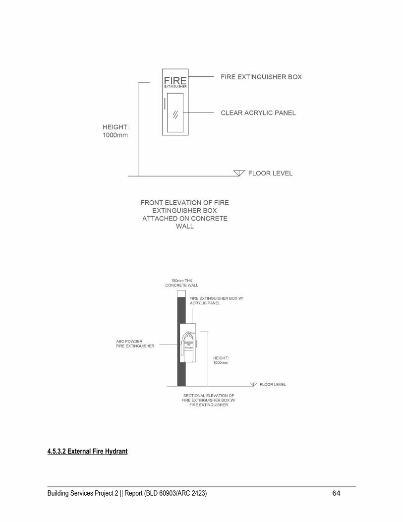
4.5.3.1 Fire Extinguishers
ABC Powder fire extinguisher
Carbon Dioxide fire extinguisher
Generally, dry powder fire extinguisher (for ABC class and electrical equipments) is the most common one among all
the types of fire extinguishers, even it does not helps at all on controlling the fire which caused by cooking oils.
Therefore, Carbon Dioxide fire extinguisher is required in the spaces such as kitchen.
Dry powder fire extinguishers that can be found in proposed building are in 6kg capacity, rather than 9kg which is
heavier for elderly or the building occupants.
Building Services Project 2 || Report (BLD 60903/ARC 2423) 63
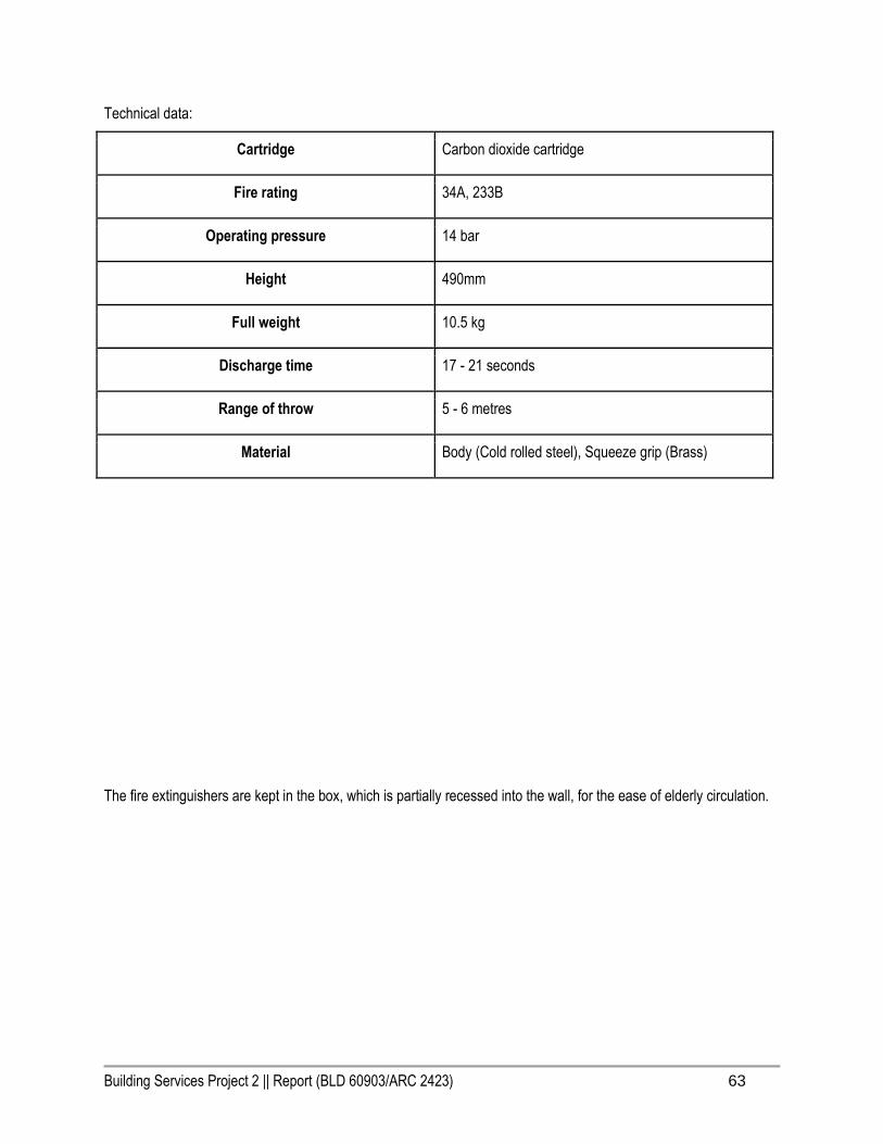
Technical data:
Cartridge Carbon dioxide cartridge
Fire rating 34A, 233B
Operating pressure 14 bar
Height 490mm
Full weight 10.5 kg
Discharge time 17 - 21 seconds
Range of throw 5 - 6 metres
Material Body (Cold rolled steel), Squeeze grip (Brass)
The fire extinguishers are kept in the box, which is partially recessed into the wall, for the ease of elderly circulation.
Building Services Project 2 || Report (BLD 60903/ARC 2423) 64
4.5.3.2 External Fire Hydrant

Building Services Project 2 || Report (BLD 60903/ARC 2423) 65
By investigating the surrounding neighbourhood, we noticed that there is only one existing fire hydrant along the
road. Therefore, we proposed one external fire hydrant to be placed where about 6500mm away from our proposed
building. According to the provisions, the spacing between two external fire hydrants shall not be more than 90
metres apart. Our proposed external fire hydrant is about 60 metres away from the existing external fire hydrant,
which is approved. The proposed external fire hydrant is located 6.5 metres from the building (by law not less than 6
metres from the building). 2 way external fire hydrant is chosen because the buildings around the area is not high
rises and the water demand under 750 gpm or 2839 lpm.
Sectional elevation of an external fire hydrant pipework and distance to proposed building:
4.5.3.3 Hose Reel System

Building Services Project 2 || Report (BLD 60903/ARC 2423) 66
Since the building is not fulfilling the requirement of dry riser (topmost floor is higher than 18.3 metres) or wet riser
(topmost floor higher than 30.5 metres) installation system, the hose reel system which directly connected to water
tank is being introduced.
Typical hose reel system arrangement:
Legends:
1. Water Tank
2. Vent Pipe c/w Mosquito Net
3. Access Opening
4. Level Indicator
5. External Cat Ladder
6. Overflow Pipe
7. Warning Pipe
8. Standby Pump
9. Eccentric Reducer
10. Expansion Joint
11. Y- Strainer
12. Gate Valve
13. Concentric Reducer
14. Check Valve
15. Duty Pump
16. Pump Start Test Pipe
17. Pump Starter Panel
18. Hose Reel c/w Hoses,
Nozzles & Accessories
19. Air Release Valve c/w Ball
Valve
20. Stop Valve
Schematic diagrams of hose reel systems pipeworks (combined with water sprinkler system):
Building Services Project 2 || Report (BLD 60903/ARC 2423) 67
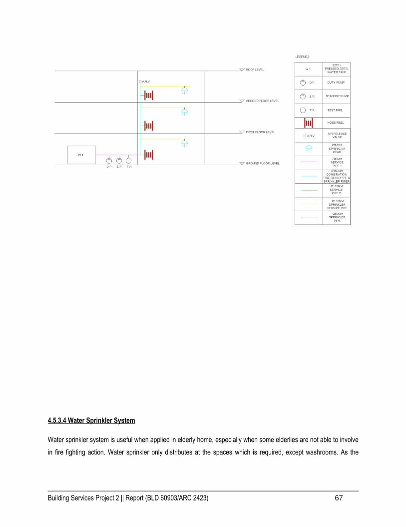
4.5.3.4 Water Sprinkler System
Water sprinkler system is useful when applied in elderly home, especially when some elderlies are not able to involve
in fire fighting action. Water sprinkler only distributes at the spaces which is required, except washrooms. As the

Building Services Project 2 || Report (BLD 60903/ARC 2423) 68
elderly home’s risk considered as extra light hazard, the spacing between water sprinkler is 4.6 metres. The radius of
water sprinkler spreading depends on the height of the water sprinkler placed.
Water sprinkler layout:
Schematic diagram of water sprinkler distribution systems (combined with hose reel systems):

Building Services Project 2 || Report (BLD 60903/ARC 2423) 69
5.0 Mechanical Ventilation System

Building Services Project 2 || Report (BLD 60903/ARC 2423) 70
5.1 Introduction
Mechanical system is an essential system in buildings and any small enclosed space to remove stale air and replace
it with fresh air. The process cycle actually works by allowing outer natural air to be pull inside the building with the
help of mechanical components.
It acts like a natural ventilation process but with incorporate using specific type of mechanical components where
systems used an electrically driven fan or fans to provide the necessary air movement. Ensuring the airflow is
constainly under certain air pressure and can be forces through the filters to create a better ventilation within the
building, which also to improve air circulation inside the building.
The type of mechanical ventilation used depends on climate. For example, in warm and humid climates like Malaysia,
infiltration may need to be minimized or prevented to reduce interstitial condensation (which occurs when warm,
moist air from inside a building penetrates a wall, roof or floor and meets a cold surface).
In these cases, mechanical ventilation is often required to ventilate the spaces. Whereas there are three types of
mechanical ventilation system which commonly being applied in Malaysia are Combination system, Extract system
and Combination system.
The objective of this project is to propose specific mechanical ventilation components into the space that required in
our elderly center final studio project. Throughout the research, Uniform Building By Law(UBBL) will be used to
ensure the rules and standards will guide us to check if the building opening dimensions, ductwork dimension , and
installation of components meet the building space requirements and regulations.

Building Services Project 2 || Report (BLD 60903/ARC 2423) 71
5.2 Literature Review
Mechanical ventilation is necessary in buildings to remove ‘stale’ air and replaced it with fresh air, due to the fact that
number of occupants will affect the comfort level in an specific space. Therefore, natural ventilation is not suitable
and effective enough to provide air exchange. Thus,ventilation system is highly concerned to reach the comfort level
of each occupants in specific spaces.
While the most basic function of mechanical ventilation system is to remove smoke and odors, which commonly
found in bathrooms and kitchen. While larger internal spaces like library, cafe, game room, service room, office,
gym, shower, staff accommodation ,pantry, karoake room, theatre will be conceal above the ceiling from being seen.
Spot ventilation is widely used in Malaysia. Spot ventilation system consist of supply system, extract system and
combination system. While for combination system, it consists of both supply and extract system that works together
through slight air pressurization using extract fan smaller than inlet fan.
Without mechanical ventilation to provide fresh air, moisture, odours and other pollutants can build up inside the
building. Therefore, mechanical system circulates fresh air using ducts and fans rather than relying on airflow
through small holes or crack’s in a home’s wall, roof or windows.
The three types of mechanical ventilation system which commonly being applied in Malaysia are extract system,
supply system and combination system.
5.2.1 Extract system
Natural inlet and mechanical outlet. The exhaust system consists of fans, it functions to extract the less dense,hot
air inside the room and cause a negative pressure in the space which cause the outlet air pressure to be higher than
the inside. Allowing the freshen air to enter to the interior spaces. Mechanical extract fans installed in windows, roofs
Building Services Project 2 || Report (BLD 60903/ARC 2423) 72
and ducted system where the air is to be discharged away from the occupied space removing heats, fumes, smoke,
water vapour and odour. This system is widely used in toilet and bathroom.
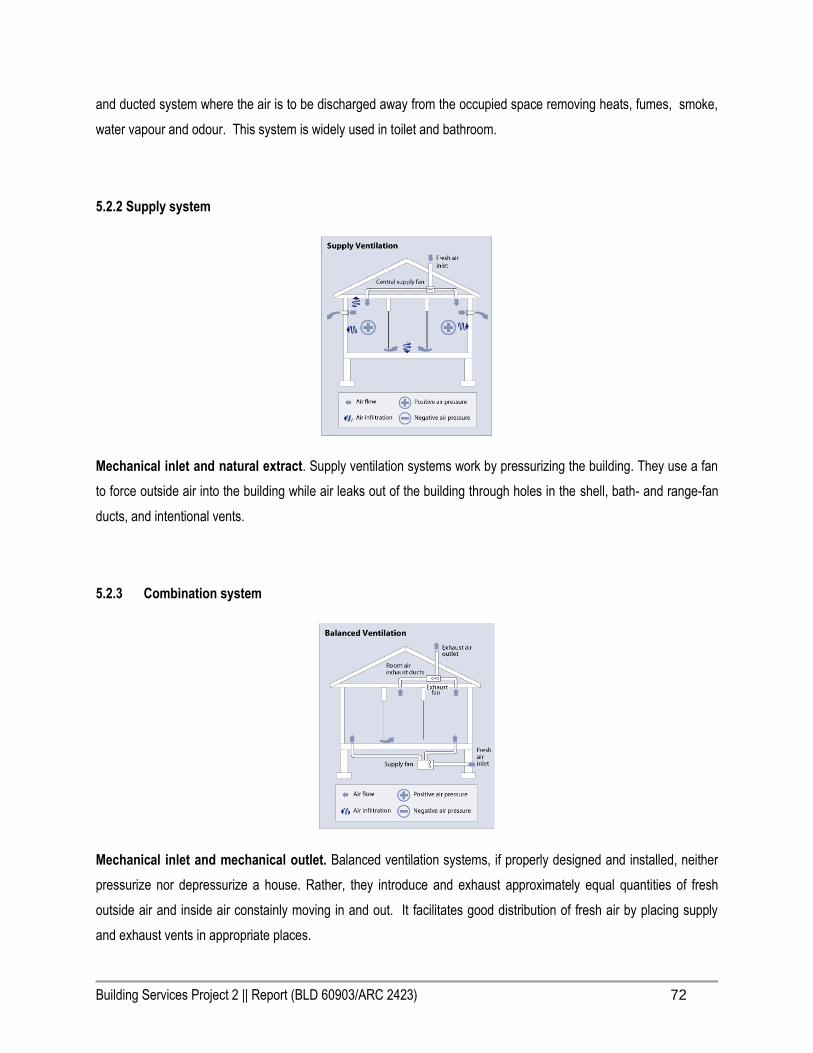
5.2.2 Supply system
Mechanical inlet and natural extract. Supply ventilation systems work by pressurizing the building. They use a fan
to force outside air into the building while air leaks out of the building through holes in the shell, bath- and range-fan
ducts, and intentional vents.
5.2.3 Combination system
Mechanical inlet and mechanical outlet. Balanced ventilation systems, if properly designed and installed, neither
pressurize nor depressurize a house. Rather, they introduce and exhaust approximately equal quantities of fresh
outside air and inside air constainly moving in and out. It facilitates good distribution of fresh air by placing supply
and exhaust vents in appropriate places.
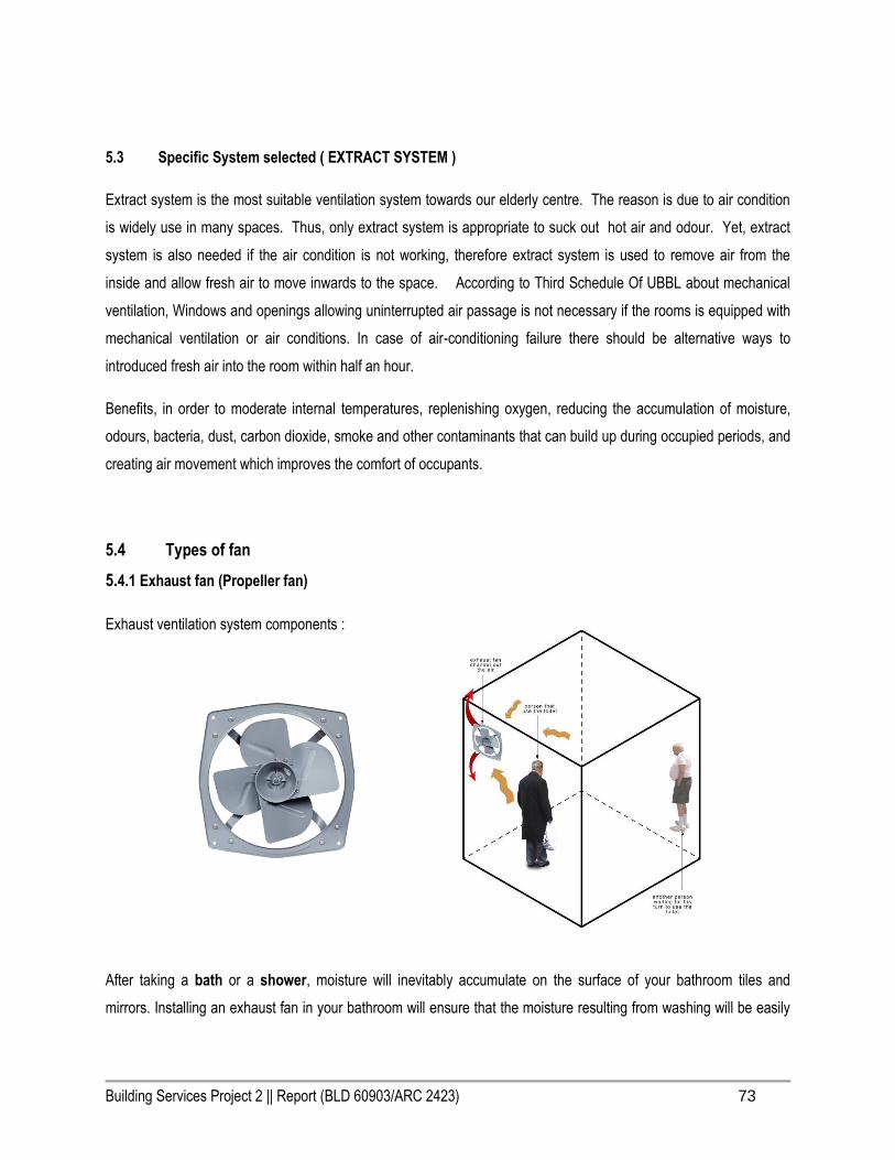
Building Services Project 2 || Report (BLD 60903/ARC 2423) 73
5.3 Specific System selected ( EXTRACT SYSTEM )
Extract system is the most suitable ventilation system towards our elderly centre. The reason is due to air condition
is widely use in many spaces. Thus, only extract system is appropriate to suck out hot air and odour. Yet, extract
system is also needed if the air condition is not working, therefore extract system is used to remove air from the
inside and allow fresh air to move inwards to the space. According to Third Schedule Of UBBL about mechanical
ventilation, Windows and openings allowing uninterrupted air passage is not necessary if the rooms is equipped with
mechanical ventilation or air conditions. In case of air-conditioning failure there should be alternative ways to
introduced fresh air into the room within half an hour.
Benefits, in order to moderate internal temperatures, replenishing oxygen, reducing the accumulation of moisture,
odours, bacteria, dust, carbon dioxide, smoke and other contaminants that can build up during occupied periods, and
creating air movement which improves the comfort of occupants.
5.4 Types of fan
5.4.1 Exhaust fan (Propeller fan)
Exhaust ventilation system components :
After taking a bath or a shower, moisture will inevitably accumulate on the surface of your bathroom tiles and
mirrors. Installing an exhaust fan in your bathroom will ensure that the moisture resulting from washing will be easily
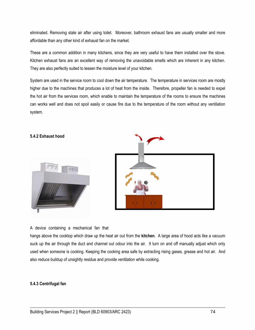
Building Services Project 2 || Report (BLD 60903/ARC 2423) 74
eliminated. Removing stale air after using toilet. Moreover, bathroom exhaust fans are usually smaller and more
affordable than any other kind of exhaust fan on the market.
These are a common addition in many kitchens, since they are very useful to have them installed over the stove.
Kitchen exhaust fans are an excellent way of removing the unavoidable smells which are inherent in any kitchen.
They are also perfectly suited to lessen the moisture level of your kitchen.
System are used in the service room to cool down the air temperature. The temperature in services room are mostly
higher due to the machines that produces a lot of heat from the inside. Therefore, propeller fan is needed to expel
the hot air from the services room, which enable to maintain the temperature of the rooms to ensure the machines
can works well and does not spoil easily or cause fire due to the temperature of the room without any ventilation
system.
5.4.2 Exhaust hood
A device containing a mechanical fan that
hangs above the cooktop which draw up the heat air out from the kitchen. A large area of hood acts like a vacuum
suck up the air through the duct and channel out odour into the air. It turn on and off manually adjust which only
used when someone is cooking. Keeping the cooking area safe by extracting rising gases, grease and hot air. And
also reduce buildup of unsightly residue and provide ventilation while cooking.
5.4.3 Centrifugal fan

Building Services Project 2 || Report (BLD 60903/ARC 2423) 75
Functions as exhaust and directional fan. Ducts are channel to each individual spaces, and it draws out the heat and
odour air where centrifugal fan located at the end of the channel. It is powerful that could increase the speed of air
stream with the rotating impellers. Giving a constant recycling of air to reach human comfort throughout the spaces.
5.4.4 Ductwork
1) Rigid Air Ducts
Sheet metal ducts: Galvanized steel and aluminum are the most common materials for sheet metal ducts.
Aluminum in particular is relatively light and easy to install. They are also the least likely to harbor dangerous molds
or growths because they have non-porous surfaces.
Fiberglass lined ducts: These are sheet metal ducts that have internal or external fiberglass lining. This type of duct
is common in office and commercial buildings, as it dampens the sound However, the fiberglass in these ducts can
deteriorate and eventually release fiberglass particles into the air – this is a major health concern, especially with
long-term exposure. Fiberglass lined ducts are also difficult to clean for this same reason: the cleaning process can
damage the lining and release fibers. These ducts can also become contaminated with molds and bacteria.
Fiberboard ducts: Fiberboard is made from fiberglass strands that have been compressed and bonded with a resin,
and then covered with a sheet of foil laminate to protect them from
moisture. This type of duct is good for cooling and heating systems because it is well insulated by itself. However, it’s
not recommended for ventilation because, like fiberglass-lined ducts, they can become a breeding ground for mold
and mildew in humid climates. Also, because the surface is rough, they can also affect airflow and efficiency.

Building Services Project 2 || Report (BLD 60903/ARC 2423) 76
PVC Duct: Resistant to microbaterial and cheap.Less noisy but doesnt stand very high and low temperatures
2) Flexible
Flexible ducts are typically tube-shaped, made of a wire coil covered with a bendable, durable plastic.The
advantages of flexible ducts are that they are fairly quick and easy to install, and often cost less than rigid ductwork
and often resistant to microbaterial.
Choosen air duct for toilet: Flexible air duct for its cost and resistance towards microbaterial.
Choosen air duct for building:
● PVC because its cheap and because mainly extract doesnt deal with high and low temperatures.
● PVC Flexible Air Duct
● Non insulated because doesnt deal with hot and cold air
● Steel Wire reinforced
Requirements for toilet :
● The mechanical ventilation rate is at least 3 air changes per hour.
● Exhaust air from bathrooms and toilet rooms shall not discharge into an attic, crawl space or other areas
inside the building.
Type of air vent filter :
Activated charcoal: Also known as carbon media filters,these are replaceable cartridges panels that have a foam or
fabric medium filled with granulated carbon activated charcoal.The carbon absorbs numerous odors and heavy
gases.
HEPA: This filter has pleated arrangement of blankets and mats whose have tiny pores that can remove very small
particulates.Able to removed fine particles including some bacteria and other chemical environments.Used mainly for
hospitals and clinics.
Viscous Impringement: This is fairly coarse and durable filter that is periodically covered all or grease.VG for
removing pollens,dusts,ashes and mists.

Building Services Project 2 || Report (BLD 60903/ARC 2423) 77
Chosen air vent filter for toilet :
Activated charcoal: due to its nature of filtering odors that is the need function for toilet ventilation
Chosen air vent filter for building:
HEPA: due to its nature of removing dust and allergens
Requirements:
● The mechanical ventilation rate is at least 3 air changes per hour.
● Exhaust air from bathrooms and toilet rooms shall not discharge into an attic, crawl space or other areas
inside the building.
Calculations for ductwork:
Toilet 1
The volume of the toilet:
5.1 x 2.8 x 3.5 = 49.98 m3
The ventilation rate in m3/h is:
Ventilation Rate (m3/h) = Room volume (m3) x air change rate (ac/h)
50 x 3
= 150
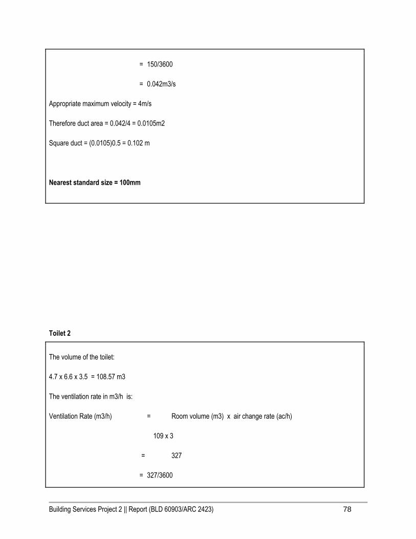
Building Services Project 2 || Report (BLD 60903/ARC 2423) 78
= 150/3600
= 0.042m3/s
Appropriate maximum velocity = 4m/s
Therefore duct area = 0.042/4 = 0.0105m2
Square duct = (0.0105)0.5 = 0.102 m
Nearest standard size = 100mm
Toilet 2
The volume of the toilet:
4.7 x 6.6 x 3.5 = 108.57 m3
The ventilation rate in m3/h is:
Ventilation Rate (m3/h) = Room volume (m3) x air change rate (ac/h)
109 x 3
= 327
= 327/3600
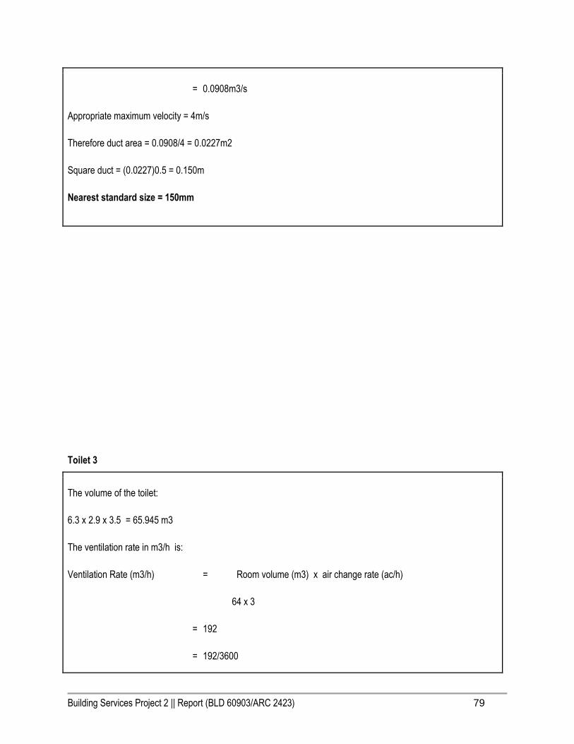
Building Services Project 2 || Report (BLD 60903/ARC 2423) 79
= 0.0908m3/s
Appropriate maximum velocity = 4m/s
Therefore duct area = 0.0908/4 = 0.0227m2
Square duct = (0.0227)0.5 = 0.150m
Nearest standard size = 150mm
Toilet 3
The volume of the toilet:
6.3 x 2.9 x 3.5 = 65.945 m3
The ventilation rate in m3/h is:
Ventilation Rate (m3/h) = Room volume (m3) x air change rate (ac/h)
64 x 3
= 192
= 192/3600

Building Services Project 2 || Report (BLD 60903/ARC 2423) 80
= 0.053 m3/s
Appropriate maximum velocity = 4m/s
Therefore duct area = 0.0503/4 = 0.01325m2
Square duct = (0.01325)0.5 = 0.115m
Nearest standard size = 150mm
Toilet 4
The volume of the toilet:
3.9 x 5.2 x 3.5 = 70.98 m3
The ventilation rate in m3/h is:
Ventilation Rate (m3/h) = Room volume (m3) x air change rate (ac/h)
71 x 3
= 213
= 213/3600

Building Services Project 2 || Report (BLD 60903/ARC 2423) 81
= 0.0592 m3/s
Appropriate maximum velocity = 4m/s
Therefore duct area = 0.0592/4 = 0.0148m2
Square duct = (0.0148)0.5 = 0.122m
Nearest standard size = 150mm
5. 5 Proposed System
GROUND FLOOR CEILING PLAN
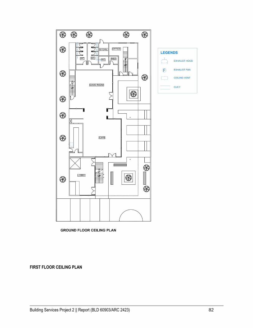
Building Services Project 2 || Report (BLD 60903/ARC 2423) 82
FIRST FLOOR CEILING PLAN

Building Services Project 2 || Report (BLD 60903/ARC 2423) 83
Building Services Project 2 || Report (BLD 60903/ARC 2423) 84
6.0 Air-Conditioning System

Building Services Project 2 || Report (BLD 60903/ARC 2423) 85
6.0 Air Conditioning System
6.1 Introduction
It is an essential investment today to select the suitable air conditioner for your home especially in a hot and humid
climate we have in Malaysia. Air conditioning system served its purpose to provide and maintain a programmed
internal environment despite of external conditions, a process of which it removes heat from a confined space. A
good air-conditioner is efficient and it provides a steady, dependable performance year after year under the condition
that it is properly maintained.
The equipment of air conditioning system includes facilities to control temperature, humidity, air cleanliness, air
movement and heat radiation. In Malaysia, tropical rainforest climate which is generally sunny throughout the year
and have high precipitation rate every month. Hence, the thermal comfort in a building is having a filtered supplied
air, with a temperature range of 20 to 28 degree Celsius and relative humidity of 55-70% to stay comfortable indoor.
In this hot and humid climate, air-conditioning system as part of the ACMV (Air-Conditioned and Mechanical
Ventilation) system is one of the crucial building service in most of the buildings typically in Malaysia to provide
thermal comfort.
The research paper is aimed to study in depth of the chosen building to have a deeper understanding of the air
conditioning system adopted by the Old Folks’ Home, a perfect example of a commercial and public building which is
an upscale neighbourhood activity centre. Through the end of this research, the rules and standards will be
investigated to ensure that proper thermal comfort and indoor air quality is being achieved via the air conditioning
system. Malaysian Standard (MS1525) and Uniform Building By-Laws (UBBL) standards will be used during the
examination.

Building Services Project 2 || Report (BLD 60903/ARC 2423) 86
6.2 Literature Review
Split Unit Air Conditioning System
The split air conditioner comprises of two parts: the outdoor unit and the indoor unit. The outdoor unit, fitted outside
the room, houses components like the compressor, condenser and expansion valve. The indoor unit comprises the
evaporator or cooling coil and the cooling fan. For this unit you don’t have to make any slot in the wall of the room.
Further, present day split units have aesthetic appeal and do not take up as much space as a window unit. A split air
conditioner can be used to cool one or two rooms.
The component of split unit air-conditioning system includes:
● Outdoor unit
● Indoor unit

Building Services Project 2 || Report (BLD 60903/ARC 2423) 87
6.3 Operating Principles of Air Cooling
Air conditioner and refrigerator works the same concept and principle as their goal is to keep the internal environment
more comfortable than it is on the outside. It was to ensure that the building is achieved thermal comfort through
efficient methodology by using air-conditioner. Like the rest, this sophisticated air-conditioning system is made up of
one major cycle: Refrigeration Cycle
6.3.1 Refrigeration Cycle
Refrigeration cycle is a process of transporting heat from one place to the another location. It serves the purpose to
discharge unwanted heat from the inside of a building space to the exterior. The refrigerant is used as a medium
where it absorbs and removes the heat produced from the space to be cooled and subsequently rejects the heat to
elsewhere. The process described below is the Refrigerant System or Refrigerant Cycle. It is the system on which
virtually all modern Air-Conditioning and refrigeration is based.
The principles of Refrigeration are as follows:
● Liquid absorbs heat when changed from liquid to gas.
● Gases give off heat when changed from gas to liquid
(Source: https://www.swtc.edu/ag_power/air_conditioning/lecture/basic_cycle.htm)

Building Services Project 2 || Report (BLD 60903/ARC 2423) 88
For an air conditioning system to operate with economy, the refrigerant must be used repeatedly. For this reason, all
air conditioners use the same cycle which is mainly divided into three main parts: compressor, condenser and an
evaporator.
The compressor and condenser are usually located on the outside air portion of the air conditioner. The evaporator is
located on the inside the house, sometimes as part of a furnace. That's the part that heats your house.
Refrigerant Cycle Process:
1. The refrigerant comes into the compressor as a low-pressure gas, it is compressed and then moves out of
the compressor as a high-pressure gas.
2. The gas then flows to the condenser. Here the gas condenses to a liquid, and gives off its heat to the
outside air.
3. The liquid then moves to the expansion valve under high pressure. This valve restricts the flow of the fluid,
and lowers its pressure as it leaves the expansion valve.
4. The low-pressure liquid then moves to the evaporator, where heat from the inside air is absorbed and
changes it from a liquid to a gas.
5. As a hot low-pressure gas, the refrigerant moves to the compressor where the entire cycle is repeated.
(Source: https://www.swtc.edu/ag_power/air_conditioning/lecture/basic_cycle.htm)

Building Services Project 2 || Report (BLD 60903/ARC 2423) 89
Compressor Condenser Evaporator
Refrigerant is drawn from the
evaporator and pumped to the
condenser by the compressor. The
compressor also pressurizes the
refrigerant vapor so that it will
change state (condense) readily.
(Source: http://image.made-in-
china.com/43f34j00RsBTNFlJpMbO
/Highly-Rotary-Compressor-for-
Home-Used-Air-Conditioner.jpg)
The high-pressure refrigerant vapor
releases heat through the
condenser coils as it condenses into
liquid refrigerant. making it easier to
vaporize.
(Source:
http://img.archiexpo.com/images_ae
/photo-g/81620-5499275.jpg)
The low-pressure liquid refrigerant
absorbs heat as it vaporizes in the
evaporator coils.
(Source:
http://www.autohausaz.com/secure/
partimages/64118384251.jpg)

Building Services Project 2 || Report (BLD 60903/ARC 2423) 90
6.4 Types of Air-Conditioning System
It can be spotted easily every building in Malaysia because of our hot and humid climate. The air conditioner are
designed in mind to accommodate different users’ need. These are the four types of air conditioning system below:
1. Window Air Conditioning System
2. Split Air Conditioning System
3. Centralized Air Conditioning System
4. Packaged Air Conditioning System
6.4.1 Window Air Conditioning System
Window air conditioners are one of the most commonly used and cheapest type of air conditioners. If your room or
office size is about less than 100 sq. ft. a window air conditioner of about 0.8 ton can be good enough. If the size of
room is more than this but less than 200 sq. ft. your HVAC designer will recommend a window air conditioner of
about 1 ton. For rooms of bigger sizes but less than 300 sq. ft. the system of about 1.5 ton is advisable. However,
these sizes may change depending upon the number of people occupying the space, its alignment with respect to
sun, and other sources of heat generation inside the room.
You will need a space on the wall as well as some open space behind the wall to install one of these units. Window
air-conditioner units are reliable and easy to be installed to keep a room cool and avoid the costly construction of a
central air system at the same time. Moreover, these units can be easily removed for storage and use the window sill
for other purposes when summer heat dies down especially in countries where they have winter.
Figure 6.4.1 Window Air Conditioning System

Building Services Project 2 || Report (BLD 60903/ARC 2423) 91
One of the complaints that window air conditioners have had is that they tend to make noise inside the room. But this
problem has been greatly overcome by the present day efficient and less noisy rotary compressors, which also
consume less electricity. Today a number of fancy and elegant looking models of window air conditioners are
available that enhance the beauty of your rooms.
6.4.2 Split Air Conditioning System
Split unit air-conditioning system is the most common type of air-conditioners used in residential housings and small
scale buildings, because of the elegant appearance and known for its soundless operation. This system mainly
comprises of two parts: which is the outdoor unit and the indoor unit.
The outdoor unit, which is fitted outside the room which contains housing components such as the compressor,
condenser and expansion valve. Whereas the indoor unit which comprises the evaporator or cooling coil and the
cooling fan. It doesn’t need any slot in the wall for this particular unit. Furthermore, the split unit has aesthetic value
and adds beauty to the space. The split air conditioner can be used to cool one or two rooms.
Figure 6.4.2.1 Split air conditioner outdoor and indoor unit

Building Services Project 2 || Report (BLD 60903/ARC 2423) 92
Figure 6.4.2.2 How split air conditioner outdoor and indoor unit works
6.4.2.1 Outdoor Unit
As mentioned before, outdoor unit comprises important components of the air conditioning system such as
compressor and condenser. While conditioning the indoor air, lots of heat is generated in this two parts.
Components of outdoor unit:
1. Compressor: It becomes the most important part ever in the whole system. The refrigerant is compressed and
pressurised before sending to the condenser. In this kind of domestic used of AC, the compressor and the motor to
drive the shaft are sealed so it cannot be seen externally. To compress the refrigerant external power is supplied and
lot of heat is produced, which means that it has to be removed by fan or other means.

Building Services Project 2 || Report (BLD 60903/ARC 2423) 93
2. Condenser: It is the coiled cooper tube in one or more than one row. The number of the rows is depending on the
size of AC unit and the compressor. The high pressured and high temperature refrigerant form the compressor will be
releasing its heat in it. Aluminium fins are covered on it in order to promote the rate of remove heat from the
refrigerant.
3. Condenser cooling fan: It is located in front the condenser and compressor. In the long run process of
pressurised and heating the refrigerant in the compressor, heats produced could be burnt the motor coils and
eventually breakdown the compressor to the whole AC system. Moreover, refrigerant within the condenser coil need
to be cooled in order to make it cool enough to produce cooling effect after expansion.
4. Expansion valve: It is where medium temperature refrigerant enter and temperature to be dropped down after the
condenser. It is normally a copper capillary tubing with several rounds of coils.
MS 1525:2007 Code 8.4.4.2
Outdoor air supply and exhaust systems should be provided with motorised or gravity dampers or other means of
automatic volume shut-off or reduction during period of non-use or alternate use of the spaces served by the
systems.
MS 1525:2007 Code 8.10 ACMV System Equipment
ACMV system equipment provides, in one (single package) or more (split unit) factory assembled packages, mean
for air-circulation, air cleaning, air cooling with controlled temperature and dehumidification. The cooling function
may be either electrically or heat operated and the refrigerant condenser may be air, water or evaporative-cooled.
6.4.2.2 Indoor Unit
It is the indoor unit that produces the cooling effect inside the room. The indoor unit of the split air conditioner is a box
type housing in which all the important parts of the air conditioner are enclosed. The most common type of the indoor
unit is the wall mounted type though other types like ceiling mounted and floor mounted are also used. We shall
discuss all these types in separate articles, here we shall discuss the wall mounted type of the indoor unit.
Components of Indoor unit:
1. Evaporator Coil or the Cooling Coil:

Building Services Project 2 || Report (BLD 60903/ARC 2423) 94
The cooling coil is a copper coil made of number turns of the copper tubing with one or more rows depending on the
capacity of the air conditioning system. The cooling coil is covered with the aluminum fins so that the maximum
amount of heat can be transferred from the coil to the air inside the room.
The refrigerant from the tubing at very low temperature and very low pressure enters the cooling coil. The blower
absorbs the hot room air or the atmospheric air and in doing so the air passes over the cooling coil which leads to the
cooling of the air. This air is then blown to the room where the cooling effect has to be produced. The air, after
producing the cooling effect is again sucked by the blower and the process of cooling the room continues.
After absorbing the heat from the room air, the temperature of the refrigerant inside the cooling coil becomes high
and it flows back through the return copper tubing to the compressor inside the outdoor unit. The refrigerant tubing
supplying the refrigerant from the outdoor unit to the indoor unit and that supplying the refrigerant from indoor unit to
the outdoor unit are both covered with the insulation tape.
2. Air Filter:
The air filter is very important part of the indoor unit. It removes all the dirt particles from the room air and helps
supplying clean air to the room. The air filter in the wall mounted type of the indoor unit is placed just before the
cooling coil. When the blower sucks the hot room air, it is first passed through the air filter and then though the
cooling coil. Thus the clean air at low temperature is supplied into the room by the blower.
One of the most popular types split air conditioners is the wall mounted type of split AC. In these ACs the indoor unit
is mounted on wall inside the room or the office.

Building Services Project 2 || Report (BLD 60903/ARC 2423) 95
3. Cooling Fan or Blower:
Inside the indoor unit there is also a long blower that sucks the room air or the atmospheric air. It is an induced type
of blower and while is sucks the room air it is passed over the cooling coil and the filter due to which the temperature
of the air reduces and all the dirt from it is removed. The blower sucks the hot and unclean air from the room and
supplies cool and clean air back. The shaft of the blower rotates inside the bushes and it is connected to a small
multiple speed motor, thus the speed of the blower can be changed. When the fan speed is changed with the remote
it is the speed of the blower that changes.
4. Drain Pipe:

Building Services Project 2 || Report (BLD 60903/ARC 2423) 96
Due to the low temperature refrigerant inside the cooling coil, its temperature is very low, usually much below the
dew point temperature of the room air. When the room air is passed over the cooling due the suction force of the
blower, the temperature of the air becomes very low and reaches levels below its dew point temperature. Due to this
the water vapor present in the air gets condensed and dew or water drops are formed on the surface of the cooling
coil. These water drops fall off the cooling coil and are collected in a small space inside the indoor unit. To remove
the water from this space the drain pipe is connected from this space extending to the some external place outside
the room where water can be disposed off. Thus the drain pipe helps removing dew water collected inside the indoor
unit.
To remove the water efficiently the indoor unit has to be a tilted by a very small angle of about 2 to 3 degrees so that
the water can be collected in the space easily and drained out. If this angle is in opposite direction, all the water will
get drained inside the room. Also, the if the tilt angle is too high, the indoor unit will shabby inside the room.
MS 1525:2007, 8.5 Piping Installation
All piping installed to serve building and within building should be adequately insulated to prevent excessive
energy losses. Additional insulation with barrier may be required to present condensation under some conditions.
5. Louvers or Fins:

Building Services Project 2 || Report (BLD 60903/ARC 2423) 97
The cool air supplied by the blower is passed into the room through louvers. The louvers help changing the angle or
direction in which the air needs to be supplied into the room as per the requirements. With louvers one easily change
the direction in which the maximum amount of the cooled air has to be passed.
There are two types of louvers: horizontal and vertical. The horizontal louvers are connected to a small motor and
there position can set by the remote control. Once can set a fixed position for the horizontal louvers so that chilled air
is passed in a particular direction only or one can keep it in rotation mode so that the fresh air is supplied throughout
the room. The vertical louvers are operated manually and one can easily change their position as per the
requirements. The horizontal louvers control flow of air in upper and downward directions of the room, while vertical
louvers control movement of air in left and right directions.
6.4.3 Centralised Air-Conditioning System
The central air conditioning plants or the systems are used for large buildings such as hotels, theaters, airports,
shopping mall and etcetera are functioned to be air conditioned completely. In comparison, the window and split air
conditioners are used for single rooms or small office spaces. It is not economically viable to place window or split air
conditioner in each and every room if the whole building is to be cooled. In addition, these small units can’t satisfy the
requirements to cool large halls, auditorium, receptions areas etcetera.

Building Services Project 2 || Report (BLD 60903/ARC 2423) 98
Figure 6.4.3.1 Centralized air conditioner system
Figure 6.4.3.2 How Centralized air conditioner system works
Components of Centralized air-conditioning system:
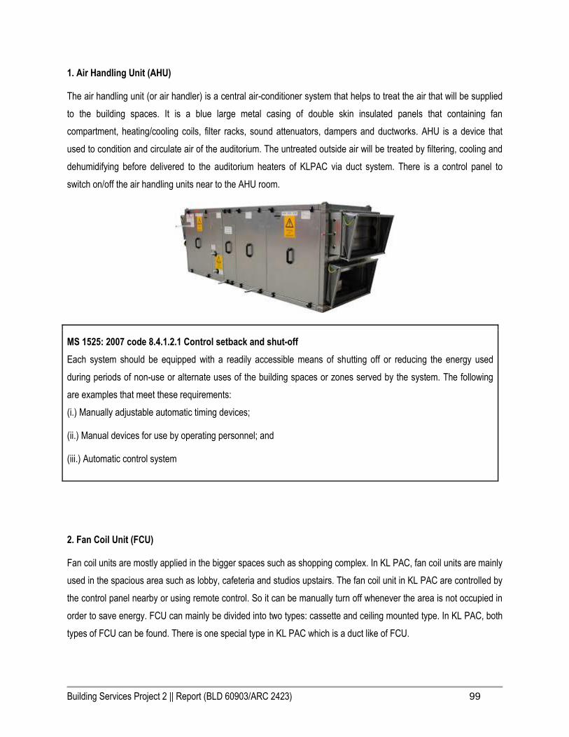
Building Services Project 2 || Report (BLD 60903/ARC 2423) 99
1. Air Handling Unit (AHU)
The air handling unit (or air handler) is a central air-conditioner system that helps to treat the air that will be supplied
to the building spaces. It is a blue large metal casing of double skin insulated panels that containing fan
compartment, heating/cooling coils, filter racks, sound attenuators, dampers and ductworks. AHU is a device that
used to condition and circulate air of the auditorium. The untreated outside air will be treated by filtering, cooling and
dehumidifying before delivered to the auditorium heaters of KLPAC via duct system. There is a control panel to
switch on/off the air handling units near to the AHU room.
MS 1525: 2007 code 8.4.1.2.1 Control setback and shut-off
Each system should be equipped with a readily accessible means of shutting off or reducing the energy used
during periods of non-use or alternate uses of the building spaces or zones served by the system. The following
are examples that meet these requirements:
(i.) Manually adjustable automatic timing devices;
(ii.) Manual devices for use by operating personnel; and
(iii.) Automatic control system
2. Fan Coil Unit (FCU)
Fan coil units are mostly applied in the bigger spaces such as shopping complex. In KL PAC, fan coil units are mainly
used in the spacious area such as lobby, cafeteria and studios upstairs. The fan coil unit in KL PAC are controlled by
the control panel nearby or using remote control. So it can be manually turn off whenever the area is not occupied in
order to save energy. FCU can mainly be divided into two types: cassette and ceiling mounted type. In KL PAC, both
types of FCU can be found. There is one special type in KL PAC which is a duct like of FCU.

Building Services Project 2 || Report (BLD 60903/ARC 2423) 100
Wall mounted FCU and Suspended ceiling FCU FCU is which a system that similar to AHU but smaller in size. It is
made up with a fan, a heating or cooling coil connected to the cold water system. It can be manually controlled the
temperature of the spaces. A fan coil unit comprises a heat exchanger in which water of circulated and a fan
assembly, incorporating a filter and simple controls. The fan coil unit is installed as a part of the ducted air system.
Air is drawn through a fan with a motor. While the air is passing through the evaporator coil or heat exchanger, the air
is cooled or heated. Wall mounted FCU is designed to fit on the perimeter wall or a ceiling mounted FCU within the
ceiling voids. It can be configured as a cassette. It is considered as pleasing looking types of AC system as the duct
can be hidden in the ceiling. FCU system gives the individually control for zones (Figure 4.5.7) and it is lower in cost
compared to others. But, it is limited in the flexibility in the units as the manufacturers fixed the operating parameters.
3. Air Cooled Chillers
Air-cooled chiller is consisted in the chilled water air-conditioning system of KLPAC to cool down the water. For air-
cooled chillers, cooling tower is not needed because it uses the evaporation and condensation process and let heat
escape from the refrigerant. The air-cooled chiller mainly contains evaporator, condenser, compressor, and an

Building Services Project 2 || Report (BLD 60903/ARC 2423) 101
expansion valve that run the system. The chiller is located outside of the building due to it releases heat and make
loud noises when operating.
MS 1525:2007 code 8.2 System and Equipment Sizing
8.2.2 Where chillers are used and when the design load is greater than 1000 kWr, a minimum of two chillers or a
single multi-compressor chiller should be provided to meet the required load.
8.2.3 Multiple units of the same equipment type, such as multiple chillers, with combined capacities exceeding the
design load may be specified to operate concurrently only if controls are provided which sequence or otherwise
optimally control the operation of each unit based on the required cooling load.
4. Duct Work
Ducts are used in heating, ventilation and air conditioning to deliver and remove air. Air ducts are connected to the
AHU and function as tunnel for the circulation of air. They distribute the modified air from the AHU to the rooms and
also deliver the recycled air from the rooms back to AHU. Air ducts are one of the methods to ensure good indoor air
quality as well as thermal comfort.

Building Services Project 2 || Report (BLD 60903/ARC 2423) 102
MS 1525:2007, Code 8.6 Air Handling duct system insulation
All ducts, plenums and enclosures installed in are on buildings should be adequately insulated to prevent
excessive energy losses. Additional insulation with vapour barriers may be required to prevent condensation under
some conditions.
6.4.4 Packaged Air Conditioning System
The window and split air conditioners are usually used for the small air conditioning capacities up to 5 tonnes. The
central air conditioning systems are used for where the cooling loads extend beyond 20 tonnes. However, the
packaged air conditioners are used for the cooling capacities in between these two extremes. The packaged air
conditioner are available in fixed rated capacities of 3, 5, 7, 10 and 15 tonnes. These units are used commonly in
places like restaurants, telephone exchanges, homes and small halls.
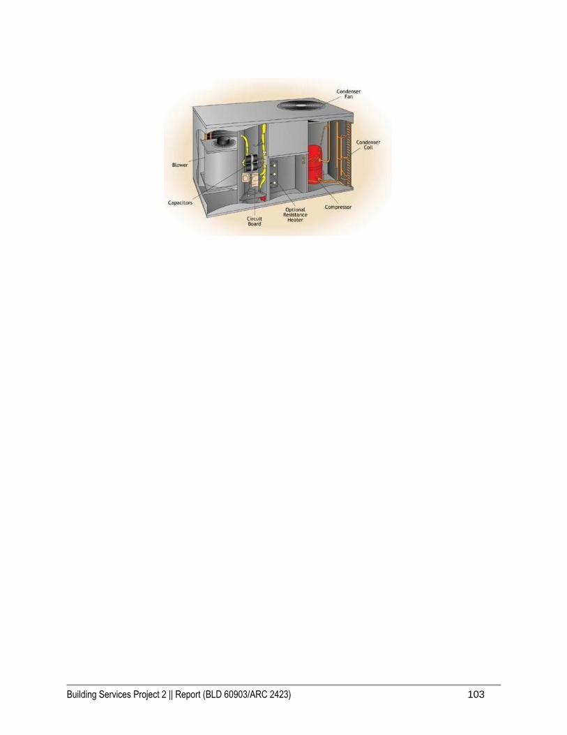
Building Services Project 2 || Report (BLD 60903/ARC 2423) 103

Building Services Project 2 || Report (BLD 60903/ARC 2423) 104
6.5 Proposal of system
In the main building of the Old Folks’ Home, split unit air conditioning system is installed. Split unit air conditioning
system consist two parts: indoor and outdoor unit.
The outdoor unit is fitted outside the room, comprising compressor condenser and expanding valve etc. Meanwhile
the indoor unit is fitted in the room and usually hang on the wall, the evaporator or cooling coil and cooling fan are
inside the indoor unit. Two box office own its split unit air conditioning system. The occupants are able to control the
temperature by using the temperature control switch according to their preferences. In the next paragraphs, the
components of both units, the location consideration and the flow of the function of split unit system will be discussed.
6.5.1 Analysis and Justifications
Consideration of the placement of outdoor unit
Outdoor unit are installed at the back façade of the facade on a rigid and flat wall to sustain its heavy weight. The
area is ensured with the sufficient air flow to remove the heat produced. The work of maintenance is easily can be
done as the outdoor unit has been placed at a place that easy to access. Thus, it has avoided to spoil the
aesthetic value of Elderly care centre in overall.
Consideration of the placement of indoor unit
The ductless indoor unit is used to reduce the installation cost for air-conditioning system as compared to the other
systems.

Building Services Project 2 || Report (BLD 60903/ARC 2423) 105
Ground Floor Plan: Split Air-Conditioning System Outdoor and Indoor Unit
The split air conditioner are placed in the Staff office and the Game room of the ground floor to ensure better air
circulation. It is also a better choice given that the rooms are small in scale and much more economicalised in
comparison to centralised system which requires a much larger space and an significant installation cost and
maintenance fee.

Building Services Project 2 || Report (BLD 60903/ARC 2423) 106
First Floor Plan: Split Air-Conditioning System Outdoor and Indoor Unit
Split Air conditioning system are placed inside the Gymnasium and Library. The placement of air-con in the
gymnasium is to prevent hot and humid air to be sent out after hot and excessive exercises are performed inside.
The Split Air conditioner is also a better option as to window air conditioner because of its aesthetical appearances
and its silent operation especially in a sound prevention room like the Library.

Building Services Project 2 || Report (BLD 60903/ARC 2423) 107
Second Floor Plan: Split Air-Conditioning System Outdoor and Indoor Unit
Last but not least the split air-conditioner on the second floor was installed one inside the Main conference room
and each one unit within the Theatre room and the Karaoke Room. The reason being that it is appropriate that the
split air conditioner is chosen because of the enclosure of each room on the second floor do not have much window
to allow air ventilation to passes through and will cause stuffiness and airblock to the users’ experiences.

Building Services Project 2 || Report (BLD 60903/ARC 2423) 108
7.0 Mechanical Transportation System

Building Services Project 2 || Report (BLD 60903/ARC 2423) 109
7.0 Mechanical Transportation System
7.1 Introduction
Mechanical Transportation is a device in which most cases is built in to the building that provides efficient and safe
transportation of people and goods. Helping persons move around the building is the primary function of the
transportation infrastructure. There are several difficult requirements that have to be satisfied by any passenger
transportation system, but the first one is safety.
There are three main types of mechanical transportation that can be found in buildings, each with their own sub
types. The three are elevator, escalator and travelators.
There are several key elements to determine the performance of any given lift,
1. Hoisting capacity, measurement of time it takes for the lift in a set to transport people to their required
destination during peak hours
2. Waiting intervals, the time it takes for any given lift to respond to a call from the patron
(Pertains to the speed in which the doors of a lift open and close, the rate at which a car accelerates, the speed of
the lift and the time it takes for patrons to leave and enter the lift )
Elevators
An elevator is a type of vertical transportation that efficiently moves people or goods between floors of a building,
vessel or other structure. Elevators are generally powered by electric motors that either drive traction cables or
counterweight systems like a hoist, or pump hydraulic fluid to raise a cylindrical piston like a jack.
Types of Elevators
● Hydraulic Elevators
● Traction Elevators
● Machine-Room-Less (MRL) Elevator
7.2 Literature Review
7.2.1 Hydraulic Elevators

Building Services Project 2 || Report (BLD 60903/ARC 2423) 110
Hydraulic elevators are supported by a piston at the bottom of the elevator that pushes the elevator up as an electric
motor forces oil or another hydraulic fluid into the piston. The elevator descends as a valve releases the fluid from
the piston. They are used for low-rise applications of 2-8 stories and travel at a maximum speed of 200 feet (61m)
per minute. The machine room for hydraulic elevators is located at the lowest level adjacent to the elevator shaft.
Advantages
Disadvantages
● Hydraulic elevators are usually cheaper to
install than the traction variety.
(Brake,ropes,pulleys,driving sheaves or
winding gear are not necessary.)
● They also occupy less space in a building, as
the hoistway requires about 10 per cent less
area.
● These elevators are also more effective when
high loads need to be moved, as the
hydraulics provide a greater lifting force than
● Hydraulic elevator is slow speed
● Hydraulic elevators use more energy than
other types of elevators because the electric
motor works against gravity as it forces
hydraulic fluid into the piston
● The performance of the oil as a hydraulic fluid
varies with temperature, so an efficient
machine-room control system is necessary
● A major drawback of hydraulic elevators is that
the hydraulic fluid can sometimes leak, which
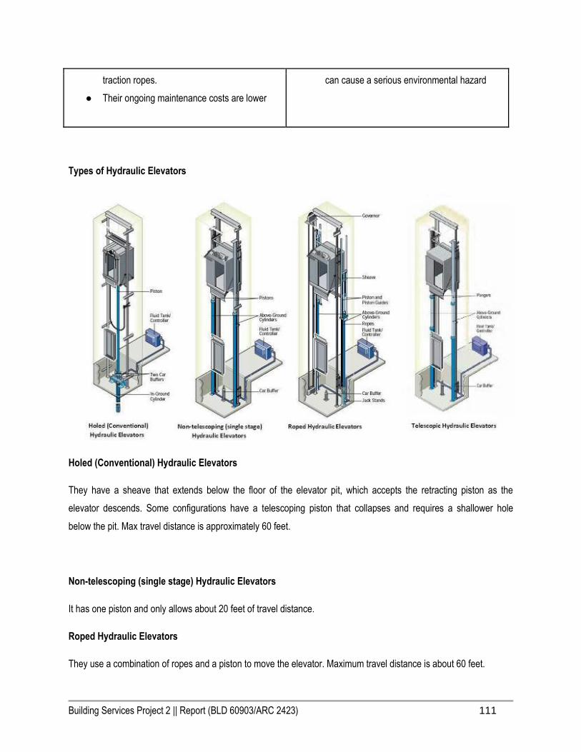
Building Services Project 2 || Report (BLD 60903/ARC 2423) 111
traction ropes.
● Their ongoing maintenance costs are lower
can cause a serious environmental hazard
Types of Hydraulic Elevators
Holed (Conventional) Hydraulic Elevators
They have a sheave that extends below the floor of the elevator pit, which accepts the retracting piston as the
elevator descends. Some configurations have a telescoping piston that collapses and requires a shallower hole
below the pit. Max travel distance is approximately 60 feet.
Non-telescoping (single stage) Hydraulic Elevators
It has one piston and only allows about 20 feet of travel distance.
Roped Hydraulic Elevators
They use a combination of ropes and a piston to move the elevator. Maximum travel distance is about 60 feet.
Building Services Project 2 || Report (BLD 60903/ARC 2423) 112
Telescopic Hydraulic Elevators
In this configuration, the telescoping pistons are fixed at the base of the pit and do not require a sheave or hole below
the pit and has 2 or 3 pieces of telescoping pistons. Telescoping pistons allow up to 50 feet of travel distance.

Building Services Project 2 || Report (BLD 60903/ARC 2423) 113
7.3 Standard Elevator Components
1. Car.
2. Hoistway.
3. Machine/drive system.
4. Safety system.
Car
The car is the component in which passengers get into when using an elevator. It is the square metal box that brings
you up and down.
Hoistway(Shaft)
The hoistway, better known as shaft, is the space in which the car goes up and down through. This is mainly where
the guard rails and cabling and etc. are located. It is one of the strongest parts of the elevator system.

Building Services Project 2 || Report (BLD 60903/ARC 2423) 114
Machine/Drive System
The machine/drive system is the component which moves the car up and down using the hoistway(shaft). Depending
on the elevator type, whether it be a pump through the hydraulic system or a traction machine through the traction
system.
Safety System
The safety system are precautions put in place if ever elevator failure or stop working. An example of would be
brakes that immediately deployed when the elevator descends too quickly.
The Hydraulic Elevators will differ from the traction elevator in the main components of:
1. Machine/drive system.
2. Safety system.
Elevator Car Standards
Standard elevator car/cabin can be classified according to the number of entrances and their locations Normal
Cabin Open, Through Cabin and Diagonal Cabin.

Building Services Project 2 || Report (BLD 60903/ARC 2423) 115
To prevent overloading of the car by persons, the available area of the car shall be limited and related to the
nominal/rated load of the elevator.
Number of passengers = rated load /75
Car size being utilized
7.4 Operating Principles of Hydraulic Elevators
Machine/ Drive System

Building Services Project 2 || Report (BLD 60903/ARC 2423) 116
1. Plunger/Piston/Jack
The cylinder shall be constructed of steel pipe of a sufficient thickness and suitable safety margin. The top of the
cylinder shall be equipped with a cylinder head with an internal guide ring and self-adjusting packing.
The plunger/Ram shall be constructed of a steel shaft of a proper diameter machined true and smooth. The plunger
shall be provided with a stop electrically welded to the bottom to prevent the plunger from leaving the cylinder
2. Hydraulic Power Unit
The hydraulic power unit consists of :
1. Tank.
2. Motor/Pump.
3. Valve.
Building Services Project 2 || Report (BLD 60903/ARC 2423) 117
4. Actuator.
Tank
The tank has sufficient capacity to provide an adequate reserve to prevent the entrance of air or other gas into the
system. A sight glass tube provided for checking the oil level and the minimum level mark clearly indicated. An oil
level monitoring device shall maintain a visual and audible signal in the control panel until the fault is rectified.
This liquid is usually oil based because it is non compressible and self lubricating.
Motor/Pump
The main function of the pump used in hydraulic elevator is constantly pushing Liquid into the cylinder to lift the
elevator, the pump is Submersible type with Variable Speed Valve Leveling.
Valve
The main functions of the Valve is to let liquid out of the system, to keeps the pressure low when open and to
increases pressure when closed.
● The valve shall incorporate the following features:
● Up and down acceleration and deceleration speed adjustment for smooth starts and stops.
● Smooth stops at each landing shall be an inherent feature of the valve.
● Adjustable pressure relief valve.
● Manually operating 'DOWN' valve to lower elevator in an emergency.
● Pressure gauge indicating in P.S.I. and Bars.
● Gate valve to isolate cylinder from pump unit.
● Negative pressure switch.
Actuator
An actuator is the device that transfers fluid or electrical energy into mechanical energy.
7.5 Safety System

Building Services Project 2 || Report (BLD 60903/ARC 2423) 118
Hydraulic elevator has dominated the low-rise market because it is cheaper to build, install and service, and because
it has a decidedly better safety record than the electric elevator. Especially in earthquake endangered areas, the
hydraulic elevator has proven itself to be clearly the safer option. Due to the threat presented by swinging
counterweights and because the car is suspended from the top of the hoistway, the traction elevator is particularly
vulnerable to a shaking building compared to the hydraulic elevator which is installed practically on the building’s
foundation.
Manual reset slack rope safety switch
A "slack/broken cable" safety device shall be supplied which will stop and sustain the elevator and its rated load, if
either of the hoisting cables become slack or breaks. The safety device shall be resettable by the operation of the
elevator in the upward direction. A switch shall be mounted in such a position as to sense the operation of the safety
device, and will open the safety circuit to the controller to prevent operation of the elevator in either direction.
Final Limit Switch
The elevator shall be equipped with a final limit switch to cut off all power to the elevator if the upper normal terminal
stopping devices fail.
Seismic valve for hydraulic elevators

Building Services Project 2 || Report (BLD 60903/ARC 2423) 119
A valve located in the pit close to the jack that is designed to hold pressure if the hydraulic line is broken due to
seismic activity.
Buffers
The buffer-striking member on the underside of the car must stop the elevator before the jack plunger reaches its
down limit of travel.
Anti-creep device
Provision shall be made to automatically return the car to the landing level at a speed not exceeding 0.15 m/s in the
event of a leakage in the hydraulic system causing the car to move downward for more than 75 mm but within the
unlocking zone.
Manual emergency operation
Readily accessible manual devices for emergency operation shall be provided in the machine room.
Other Safety Devices
● Automatic bi-directional levelling.
● Pit switch.
● Pump run timer.
● Car top stop switch.
● Emergency battery back-up for lighting, alarm and lowering
● Cab gate safety switch.
7.6 Types of Elevators
● Hydraulic Elevators
● Traction Elevators
● Machine-Room-Less (MRL) Elevator
Hydraulic Elevators
Building Services Project 2 || Report (BLD 60903/ARC 2423) 120
Hydraulic elevators are supported by a piston at the bottom of the elevator that pushes the elevator up as an electric
motor forces oil or another hydraulic fluid into the piston. The elevator descends as a valve releases the fluid from
the piston. They are used for low-rise applications of 2-8 stories and travel at a maximum speed of 200 feet (61m)
per minute. The machine room for hydraulic elevators is located at the lowest level adjacent to the elevator shaft.
Traction Elevators
Traction elevators are lifted by ropes, which pass over a wheel attached to an electric motor above the elevator shaft.
They are used for mid and high-rise applications and have much higher travel speeds than hydraulic elevators. A
counter weight makes the elevators more efficient by offsetting the weight of the car and occupants so that the motor
doesn't have to move as much weight.
● Geared Traction Elevators have a gearbox that is attached to the motor, which drives the wheel that
moves the ropes. Geared traction elevators are capable of travel speeds up to 500 feet(152.4m) per
minute. The maximum travel distance for a geared traction elevator is around 250 feet(76.2m).
● Gear-less Traction Elevators have the wheel attached directly to the motor. Gear-less traction elevators
are capable of speeds up to 2,000 feet(609.6m) per minute and they have a maximum travel distance of
around 2,000 feet(609.6m) so they are the only choice for high-rise applications.
Machine-Room-Less (MRL) Elevator
Machine-Room-Less Elevators are traction elevators that do not have a dedicated machine room above the elevator
shaft. The machine sits in the override space and is accessed from the top of the elevator cab when maintenance or
repairs are required. The control boxes are located in a control room that is adjacent to the elevator shaft on the
highest landing and within around 150 feet(45.72m) of the machine.

Building Services Project 2 || Report (BLD 60903/ARC 2423) 121
Ground Floor Plan with Lift indications and distance
Building Services Project 2 || Report (BLD 60903/ARC 2423) 122
7.7 Uniform Building By-Law & Other Requirements
152. (1) Every opening in a lift shaft or lift entrance shall open one into a protected lobby unless other suitable means
of protection to the opening to the satisfaction of the local authority is provided. These requirements shall not apply to
open type industrial and other special buildings as may be approved by the D.G.F.S.
(3) No glass shall be used for in landing doors except for vision in which case any vision panel shall or be glazed with
wired safety glass, and shall not be more than 0.0161 square metre and the total area of one of mote vision panels in
any landing door shall be not more than 0.0156 square metre.
Some of the more technical requirements are that the distance from the wall of the lift lobby to the lift doors must be a
minimum of 2.4m (Strakosch & Caporale 2010).
8.0 Conclusion
Through this assignment, we are able to identify types and ways of systems and components
selected to make sure it fits the users’ needs. Meet the users’ requirement to reach a total level of

Building Services Project 2 || Report (BLD 60903/ARC 2423) 123
thermal comfort living in a comfortable environment. We are also able to identify the estimate
dimension of components and the space required for system to perform well for these components.
Besides that, the positioning, placing and the way it built must follow the procedure UBBL and must
be based on standard rules that has been set up. Now we all now that to design a building with
applying all the services or system is not as easy as we design a building. Lastly, we are all very
thankful and grateful that we now can understand well with all the building services.
Building Services Project 2 || Report (BLD 60903/ARC 2423) 124
9.0 References & Citation
9.1 Fire Protection System
Bibliography:Board, L. R., & International Law Book Services Malaysia (2003). Uniform building by-
laws, 1984 [G.N. 5178/85] (as at 5th July 1993). Petaling Jaya, Selangor Darul Ehsan: International
Law Book Services.In-line Citation:(Board & International Law Book Services Malaysia, 2003)
NBS. [Archive] approved documents. Retrieved November 25, 2016,
from https://www.thenbs.com/B…/KnowledgeCentre/ShowContents.aspx…
Ltd, D. B. (2016). Fire compartment - designing buildings Wiki. Retrieved November 25, 2016,
from https://www.designingbuildings.co.uk/wiki/Fire_compartment
9.2 Mechanical Ventilation System
Bibliography:Retrieved November 25, 2016,
from http://www.greenheck.com/…/cata…/KVSHoods_catalog.pdfIn-line Citation:([CSL STYLE
ERROR: reference with no printed form.])
Bibliography:Technologies, P. (2016). Axial vs. Centrifugal fans. Retrieved November 25, 2016,
from http://www.pelonistechnologies.com/…/axial-vs.-centrifugal-… Citation:(Technologies, 2016)
Bibliography:How does an exhaust fan work? (2016). Retrieved November 25, 2016, from home-
garden, https://www.reference.com/…/exhaust-fan-work-87a807340450ce… Citation:(“How does an
exhaust fan work?,” 2016)
9.3 Air Conditioning System
Bibliography:Reports, 2016 C. (2016, October 31). Central air conditioning buying guide. Retrieved
November 25, 2016, from http://www.consumerreports.org/…/ce…/buying-guide.htmIn-
line Citation:(Reports, 2016)
Bibliography:Osman, N. I. (2013, September 10). Vishwas Sahni. Retrieved November 25, 2016,
from http://www.slideshare.net/No…/air-conditioning-systemIn-line Citation:(Osman, 2013)
Bibliography:Company, R. M. (2004). Choosing an air conditioning system. Retrieved November 25,
2016, from http://www.rheem.com/…/choose_air_conditioning_syst…/In-line Citation:(Company,
2004)
Bibliography:Top Ten things about air conditioning. Retrieved November 25, 2016,
from https://www.ashrae.org/…/top-ten-things-about-air-condition… Citation:(“Top Ten things about
air conditioning,” n.d.)
Bibliography:admin. (2015, October 28). Air-conditioning: Central air-conditioning applications.
Retrieved November 25, 2016, from hvac machinery, http://machineryequipmentonline.com/…/air-
condition…/In-lineCitation:(admin, 2015)

Building Services Project 2 || Report (BLD 60903/ARC 2423) 125
Bibliography:elmoaty, mostafa abd. (2015, August 17). Samy nabil. Retrieved November 25, 2016,
from http://www.slideshare.net/…/central-air-conditioning-system… Citation:(elmoaty, 2015)
Bibliography:Chilled water air conditioning. Retrieved November 25, 2016, from http://www.perfect-
home-hvac-design.com/chilled-water-air-c…Citation:(“Chilled water air conditioning,” n.d.)
9.4 Mechanical Transportation System
Elevators & Escalators - MITSUBISHI ELECTRIC. (n.d.). Retrieved November 24, 2016,
from http://www.mitsubishielectric.com/…/…/elevators/systems.html
Vertical Transportation. (n.d.). Retrieved November 24, 2016, from http://www.wsp-
pb.com/…/P…/Services/Vertical-Transportation/
Mechanical system. (n.d.). Retrieved November 24, 2016,
from https://global.britannica.com/topic/mechanical-system
Elevator Types - archtoolbox.com. (n.d.). Retrieved November 24, 2016,
from https://www.archtoolbox.com/…/vertical-c…/elevatortypes.html
Elevators Types and Classification - Part One. (n.d.). Retrieved November 24, 2016,
from http://www.electrical-knowhow.com/…/elevators-types-and-cla…
X. (n.d.). Types of Elevators / Classification of Elevators. Retrieved November 24, 2016,
from http://www.elevatorstudy.com/…/types-of-elevators-classific…
●