Building Construction: Experiencing Construction
57
-
Upload
andrew-chee-man-shing -
Category
Documents
-
view
231 -
download
30
description
Building Construction project which teaches us about experiencing, documenting and analysing construction processes.
Transcript of Building Construction: Experiencing Construction

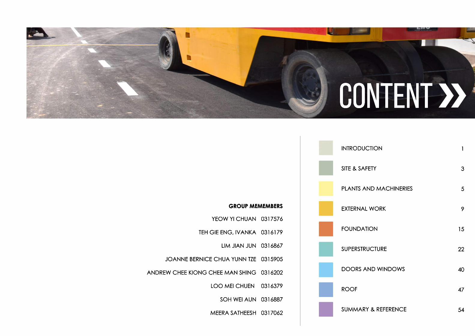
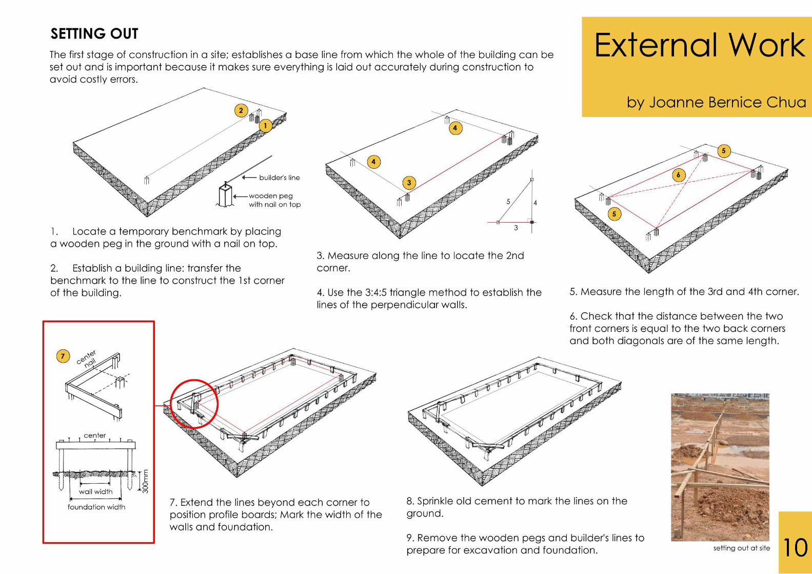
INTRODUCTION
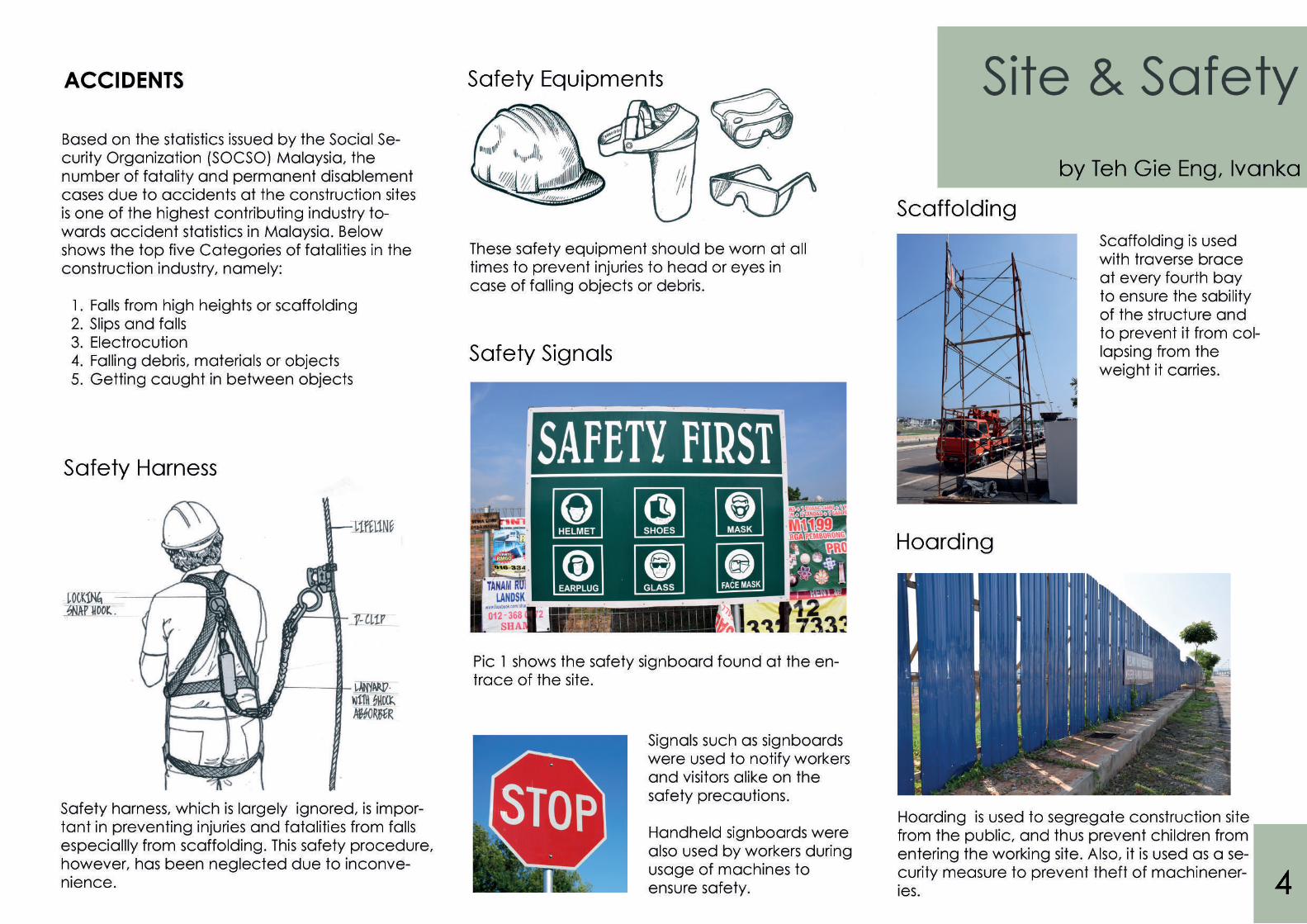
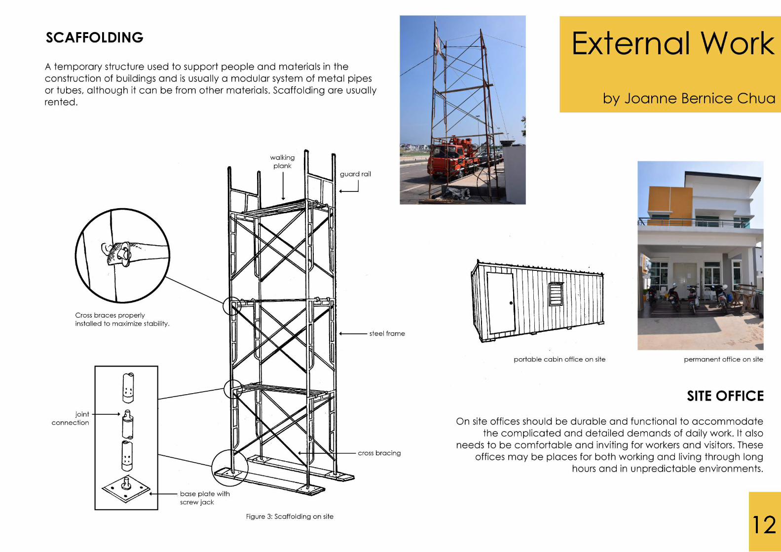
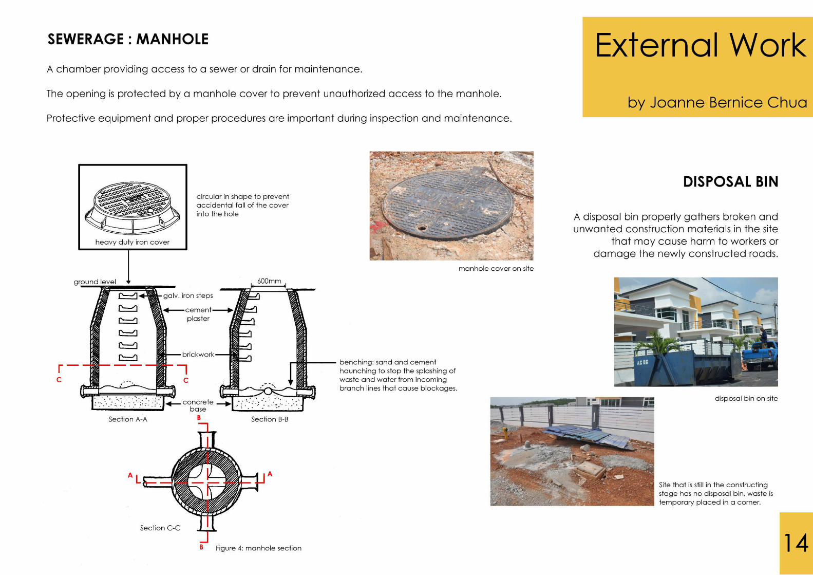
SITE & SAFETY
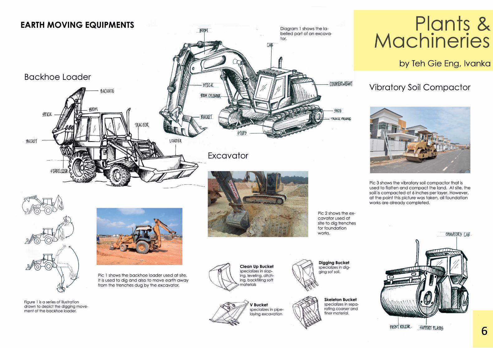
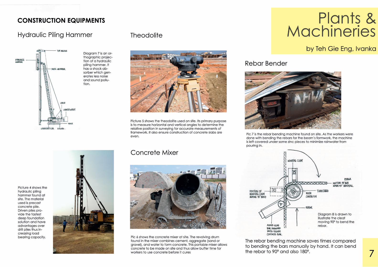
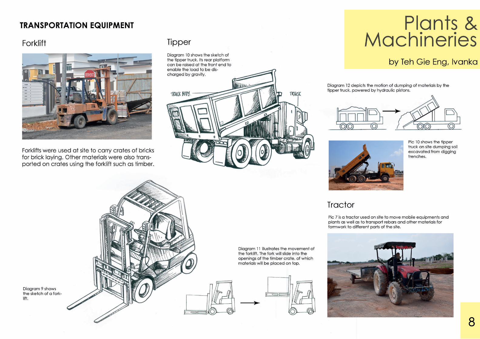
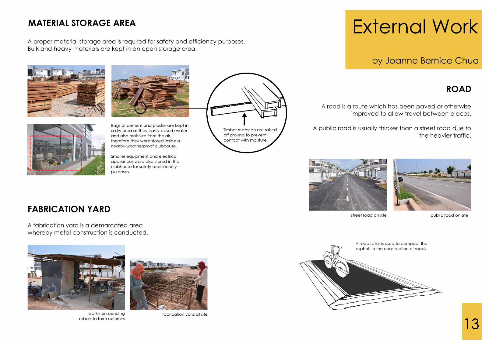
PLANTS AND MACHINERIES
EXTERNAL WORK
FOUNDATION
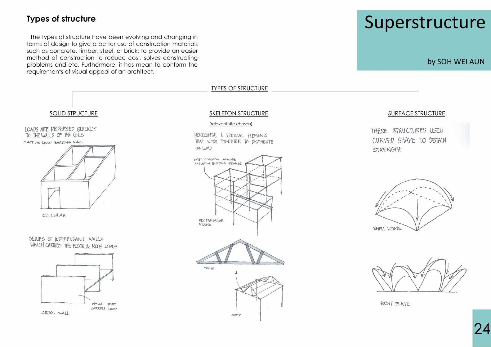
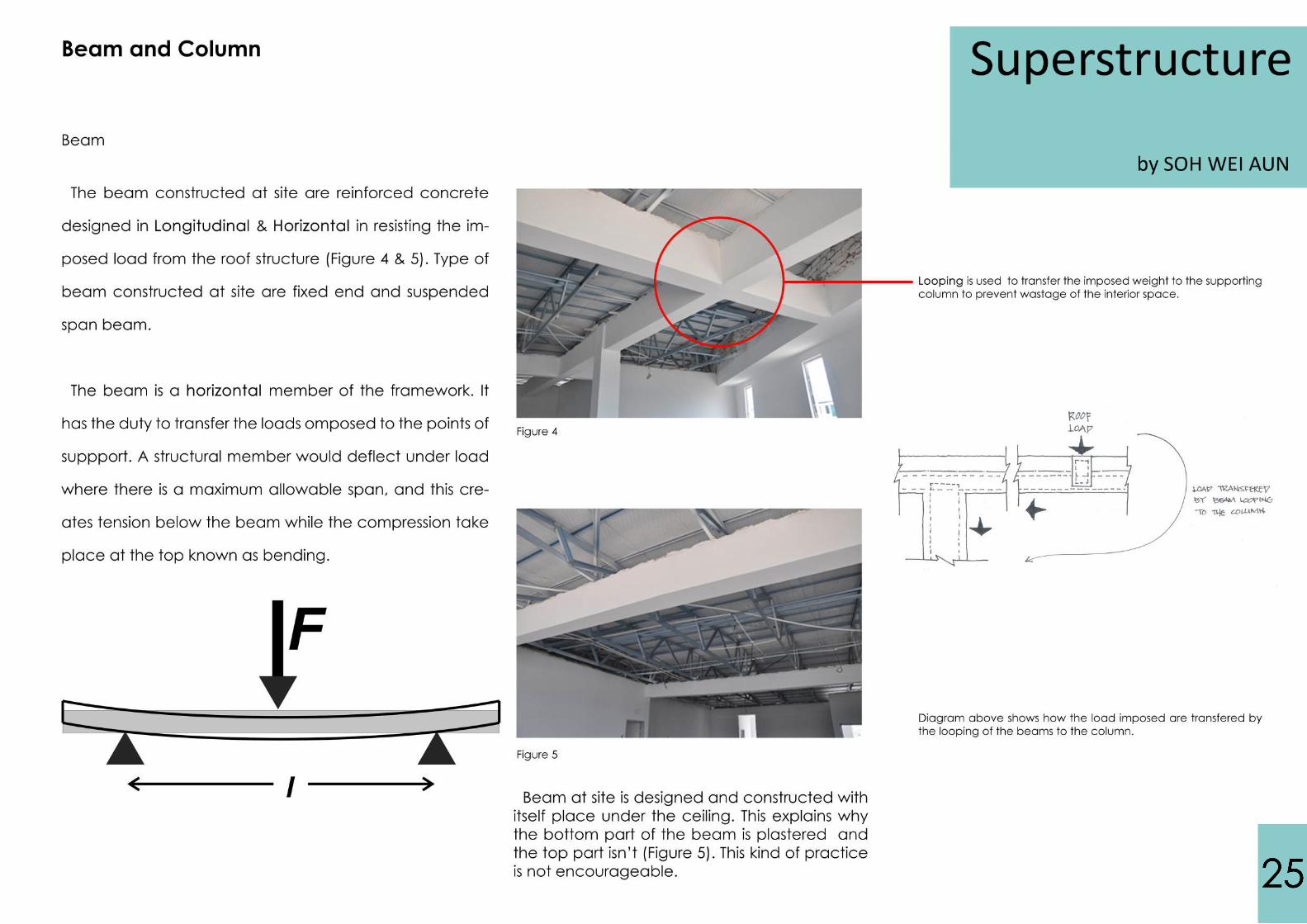
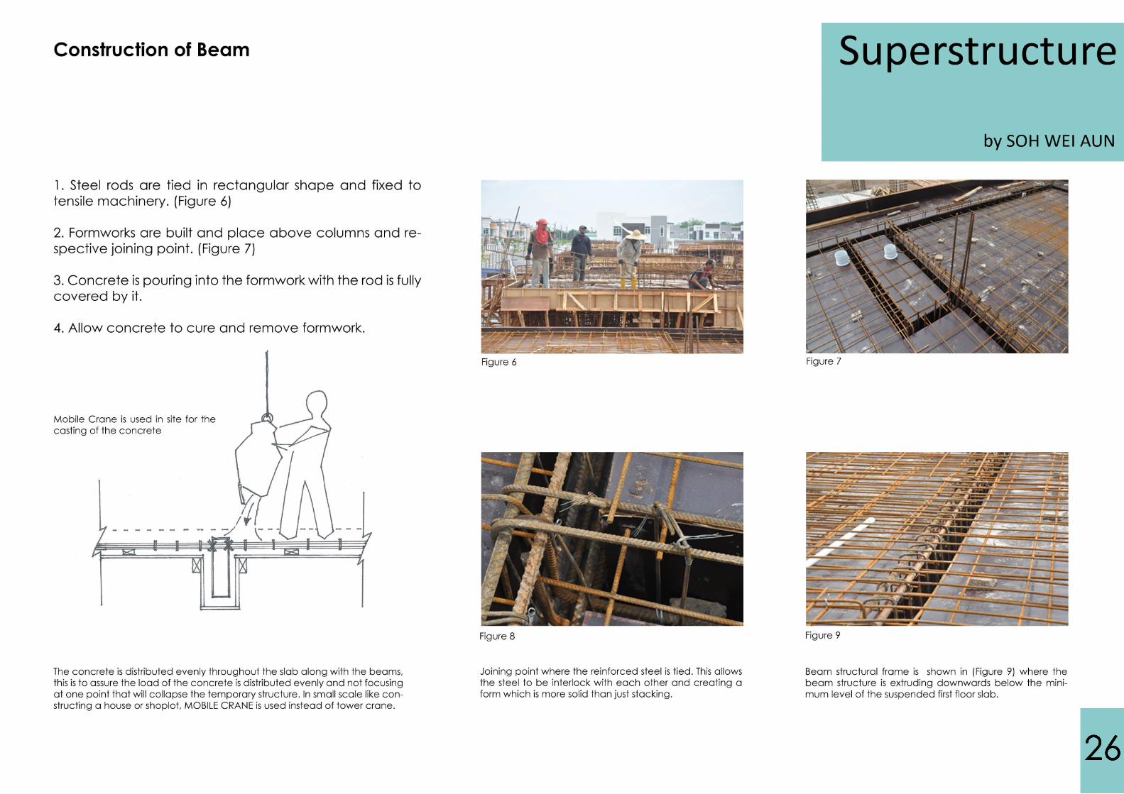
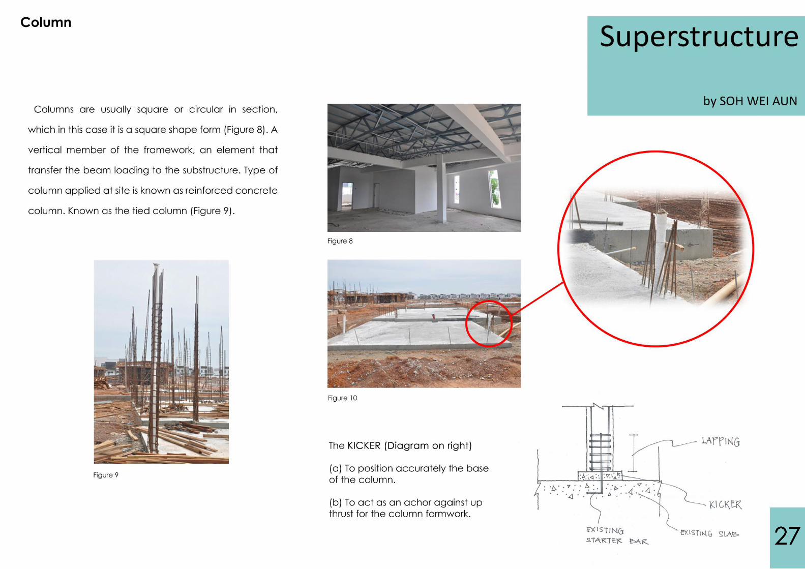
SUPERSTRUCTURE
DOORS AND WINDOWSDOORS AND WINDOWS
ROOF
SUMMARY & REFERENCE
YEOW YI CHUAN
TEH GIE ENG, IVANKA
LIM JIAN JUN
JOANNE BERNICE CHUA YUNN TZE
ANDREW CHEE KIONG CHEE MAN SHING
LOO MEI CHUEN
SOH WEI AUNSOH WEI AUN
MEERA SATHEESH
0317576
0316179
0316867
0315905
0316202
0316379
03168870316887
0317062
GROUP MEMEMBERS
1
3
5
9
15
22
4040
47
54
CONTENT

1
3
4

5
6
7
8

9
10

11
12
13
14

15

Truck for transporting topsoil and trees
Backhoe-loaderfor topsoil removal
10 tons mechanical compactor
Step 2: Earth Compacting
- Earth is compacted using 10 ton compactor
by Loo Mei Chuen &Yeow Yi Chuan

- A layer of hardcore is added to strengthen the base- Hardcore is then being compacted to 6 inches thick
- Quarry dust added after hardcore- Quarry dust is then being compacted to 6 inches thick
Foundationby Loo Mei Chuen &
Yeow Yi Chuan
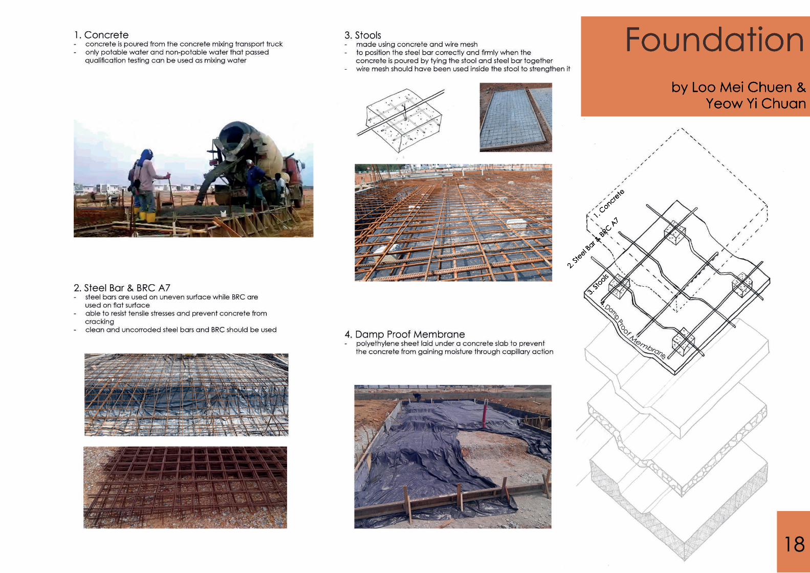
1. Concrete
2. Steel Bar & BRC A7
3. Stools
4.
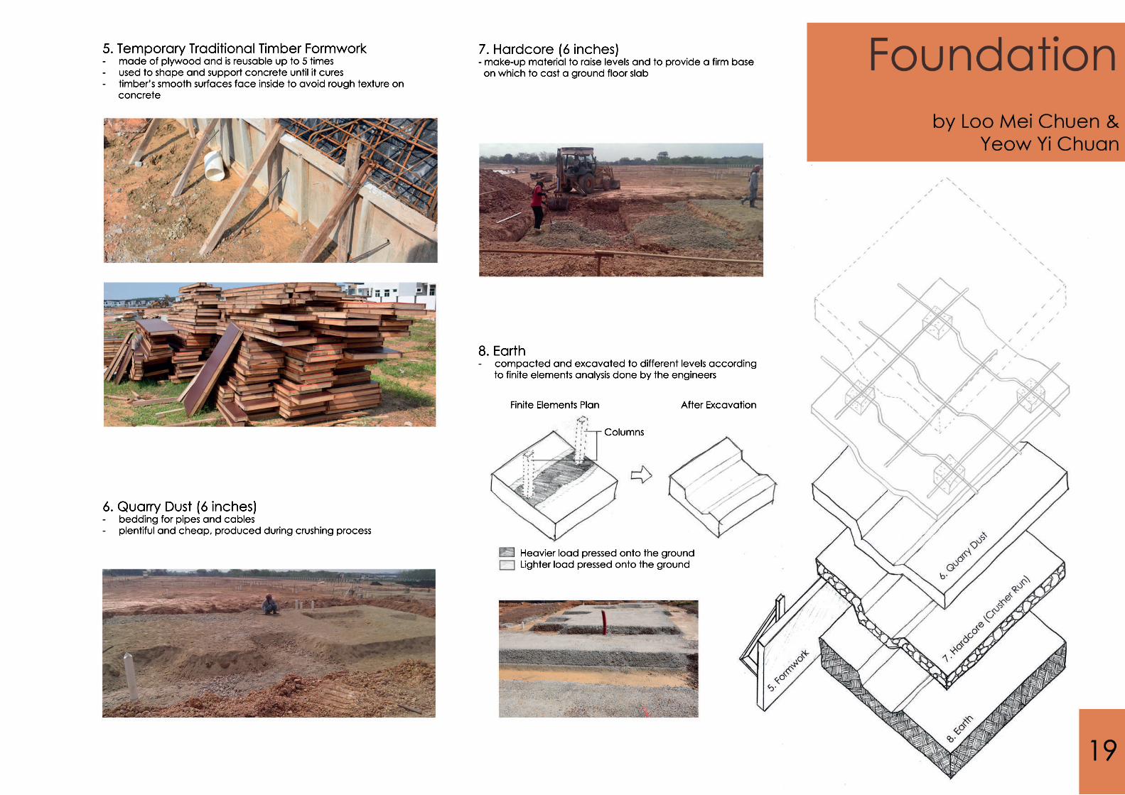
5. Temporary Traditional Timber Formwork- made of plywood and is reusable up to 5 times- used to shape and support concrete until it cures- timber’s smooth surfaces face inside to avoid rough texture on concrete
6. Quarry Dust (6 inches)- bedding for pipes and cables- bedding for pipes and cables- plentiful and cheap, produced during crushing process
7. Hardcore (6 inches)- make-up material to raise levels and to provide a firm base on which to cast a ground floor slab
8. Earth- compacted and excavated to different levels according to finite elements analysis done by the engineers
Finite Elements Plan After Excavation Columns
Heavier load pressed onto the ground Lighter load pressed onto the ground
Foundationby Loo Mei Chuen &
Yeow Yi Chuan
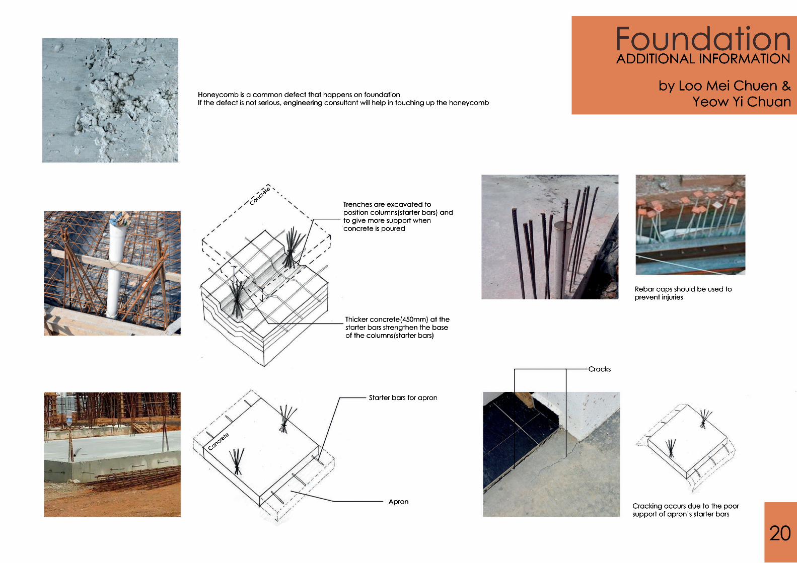
Cracking occurs due to the poor support of apron’s starter bars
Cracks
Rebar caps should be used to prevent injuries
Wall
Raft foundation
Apron
Starter bars for apron
Concrete
Trenches are excavated to position columns(starter bars) and to give more support when concrete is poured
Thicker concrete(450mm) at the starter bars strengthen the base of the columns(starter bars)
Concrete
Honeycomb is a common defect that happens on foundationIf the defect is not serious, engineering consultant will help in touching up the honeycomb
ADDITIONAL INFORMATION
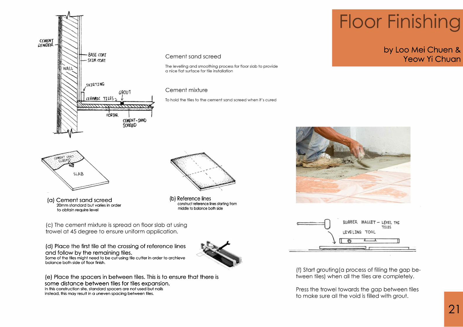
(d) Place the first tile at the crossing of reference lines and follow by the remaining tiles. Some of the tiles might need to be cut using tile cutter in order to archieve balance both side of floor finish.
(e) Place the spacers in between tiles. This is to ensure that there is some distance between tiles for tiles expansion.
cement sand screed
(a) Cement sand screed 20mm standard but varies in order to obtain require level
(b) Reference lines construct reference lines starting from middle to balance both side
In this construction site, standard spacers are not used but nails instead, this may result in a uneven spacing between tiles.
by Loo Mei Chuen &Yeow Yi Chuan

22

23
24
25
26
27
28
29
30
31

32
33

34
ANDREW CHEE KIONG CHEE MAN SHING
SUPERSTRUCTURESTAIRS
35
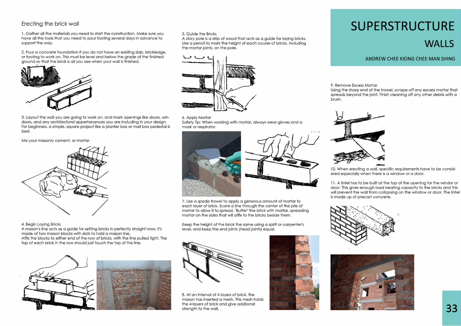
Stairs may be made from timber, bricks, stone, metal and plain and reinforced cement concrete.
Stair Types: Materials
WOOD• light in weight• easy to construct• have poor resistance to fire• used only for small residential buildings•• unsuitable for high-rise residential buildings and public and commercial buildings• timber used for construction should be free from fungal decay and insect attack and should be well treated before use
CONCRETE• form of stair and individual treads and risers may vary as desired• used where fire proof construction is required•• the width, rise, going, headroom and the arrangement of the flights of steps all are same as in timber stairs• cantilevered designs are possible• extensive form work and weight of construction is an important considerations• pre-cast stair elements are available
IN SITU REINFORCED CONCRETE•Concrete poured on site. A variety of stair types or arrangements are possible.
PRE-CAST CONCRETE SPRE-CAST CONCRETE STAIRS•Produced in most formats used for in-situ concrete stairs. Limited stair types.
STEEL• looks not good, makes lot of noise when used• requires regular maintenance in the form of painting to protect from corrosion• mostly spiral stairs• both steel tubes and angles are used•• made up of mild steel (MS) or cast iron• used in very exceptional / rare cases as emergency stairs• also used as fire escape stairs / back stairs
Measurement
The rise height or rise of each step is measured from the top of one tread to the next. The tread depth of a step is measured from the edge of the nosing to the vertical riser.The going of a step is measured from the edge of the nosing to the edge of nosing in plan view.The total run or total going of the stairs is the horizontal distance from the first riser to the last risethe last riser. - If there are N steps, the total run equals N-1 times the going: the tread of the last step is part of a landing and is not counted.The total rise of the stairs is the height between floors (or landings) that the flight of stairs is spanning. - If there are N steps, the total rise equals N times the rise of each step.The slope or pitch of the stairs is the ratio between the rise and the going (not the tread depth, due to the nosing). depth, due to the nosing). Headroom is the height above the nosing of a tread to the ceiling above it.
Total Rise
Total Run
Rise
Going
ANDREW CHEE KIONG CHEE MAN SHING
SUPERSTRUCTURESTAIRS
36
Stairs
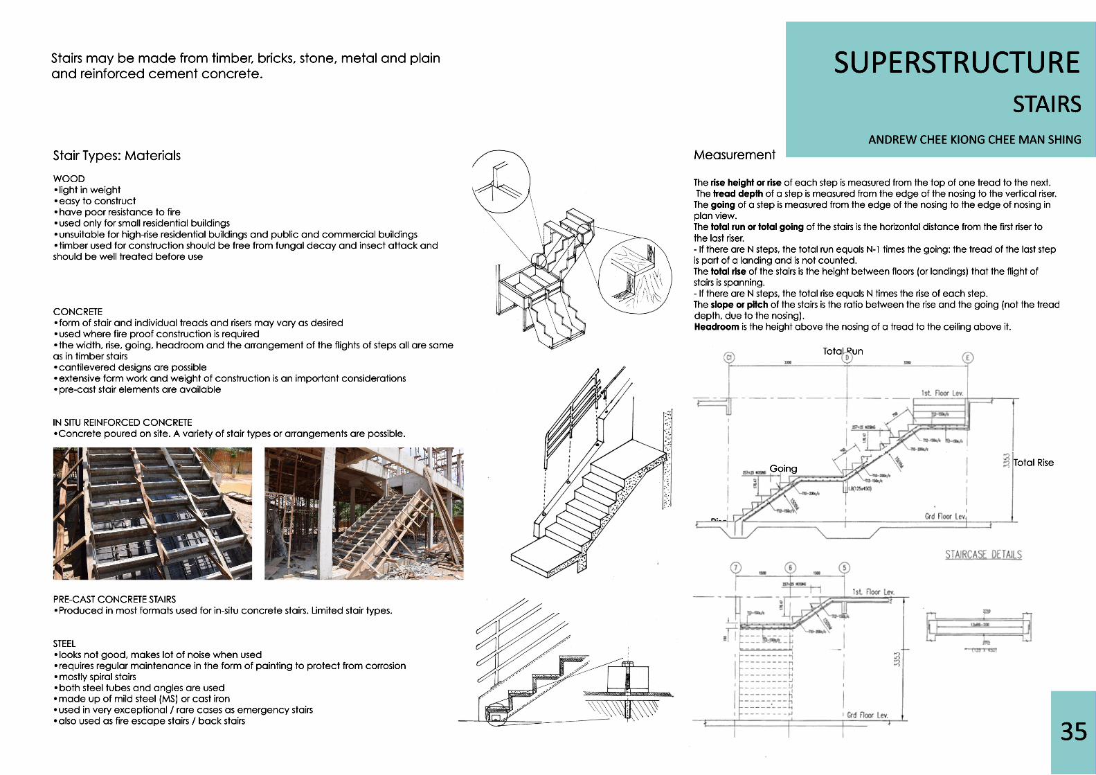
•Several fixtures, such as screws, are used to join and fasten the riser boards to the lateral structure of the formwork.
•The reinforcing bars (joist) are installed in the formwork at the bottom of the slab
Methods of Installation: In situ Reinforced Concrete Stairs
In a more detailed perspective view, the formwork will vary for different types of reinforced stairs but the basic principles for each format are the same.
• Solid wooden boards must be load bearing to support the weight of the concrete.
ANDREW CHEE KIONG CHEE MAN SHING
SUPERSTRUCTURESTAIRS
37
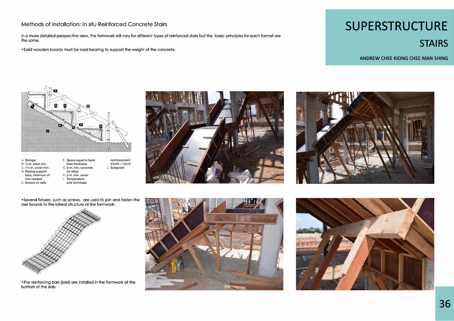
Construction of the staricase
•Mark the rise and tread on the lateral wood planks•Use of a sprit to make sure the form is level and plumb to achieve a neat look
Simple reinforced concrete steps with suitable form work arrangement is based on the following basic requirements:• concrete mix usually M15 (1:2:4) / 20mm aggregate• minimum “cover” to reinforcement 15mm or bar diameter or greater value for 1 hour fire resistance
1. 2. 3.
4. 5. 6.
ANDREW CHEE KIONG CHEE MAN SHING
SUPERSTRUCTURESTAIRS
38
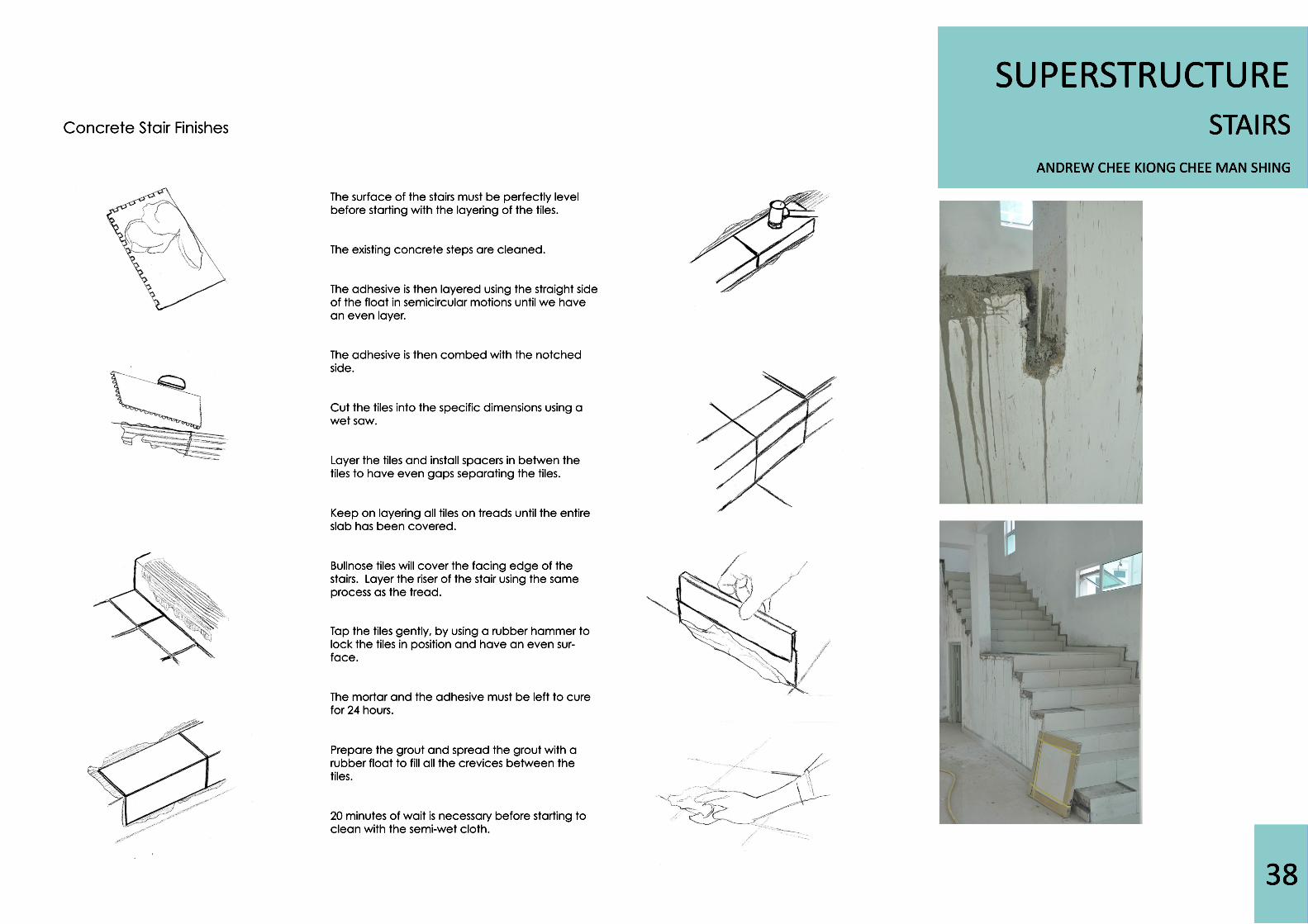
The surface of the stairs must be perfectly level before starting with the layering of the tiles.
The existing concrete steps are cleaned.
The adhesive is then layered using the straight side of the float in semicircular motions until we have an even layer.
The adhesive is then combed with the notched The adhesive is then combed with the notched side.
Cut the tiles into the specific dimensions using a wet saw.
Layer the tiles and install spacers in betwen the tiles to have even gaps separating the tiles.
Keep on layering all tiles on tKeep on layering all tiles on treads until the entire slab has been covered.
Bullnose tiles will cover the facing edge of the stairs. Layer the riser of the stair using the same process as the tread.
TTap the tiles gently, by using a rubber hammer to lock the tiles in position and have an even sur-face.
The mortar and the adhesive must be left to cure for 24 hours.
Prepare the grout and spread the grout with a rubber float to fill all the crevices between the tiles.
20 minutes of wait is necessary before starting to clean with the semi-wet cloth.
Concrete Stair Finishes
ANDREW CHEE KIONG CHEE MAN SHING
SUPERSTRUCTURESTAIRS
39
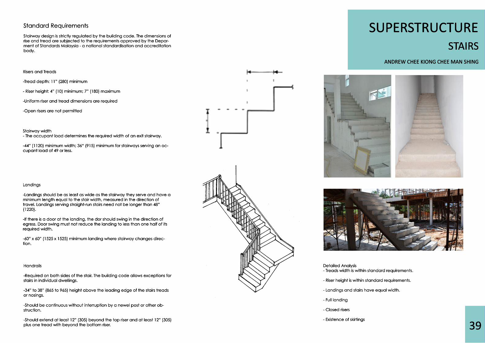
Standard Requirements
Stairway design is strictly regulated by the building code. The dimensions of rise and tread are subjected to the requirements approved by the Depar-ment of Standards Malaysia - a national standardisation and accreditation body.
Risers and Treads
-Tread depth: 11” (280) minimum
- Riser height: 4” (10) minimum; 7” (180) maximum
-Uniform riser and tread dimensions are required
-Open risers are not permitted
Stairway width- The occupant load determines the required width of an exit stairway.
-44” (1120) minimum width; 36“ (915) minimum for stairways serving an oc-cupant load of 49 or less.
Landings
-Landings should be as least as wide as the stairway they serve and have a minimum length equal to the stair width, measured in the direction of travel. Landings serving straight-run stairs need not be longer than 48” (1220).
-If there is a door at the landing, the dor should swing in the direction of egress. Door swing must not reduce the landing to less than one half of its required width.
-60” x 60” (1525 x 1525) minimum landing whe-60” x 60” (1525 x 1525) minimum landing where stairway changes direc-tion.
Handrails
-Required on both sides of the stair. The building code allows exceptions for stairs in individual dwellings.
-34” to 38” (865 to 965) height above the leading edge of the stairs treads or nosings.
-Should be continuous without interruption by a newel post or other ob-Should be continuous without interruption by a newel post or other ob-struction.
-Should extend at least 12” (305) beyond the top riser and at least 12” (305) plus one tread with beyond the bottom riser.
Detailed Analysis- Treads width is within standard requirements.
- Riser height is within standard requirements.
- Landings and stairs have equal width.
- Full landing
- Closed risers
- Existence of skirtings- Existence of skirtings

40
ANDREW CHEE KIONG CHEE MAN SHING
DOORS & WINDOWSDOORS
41
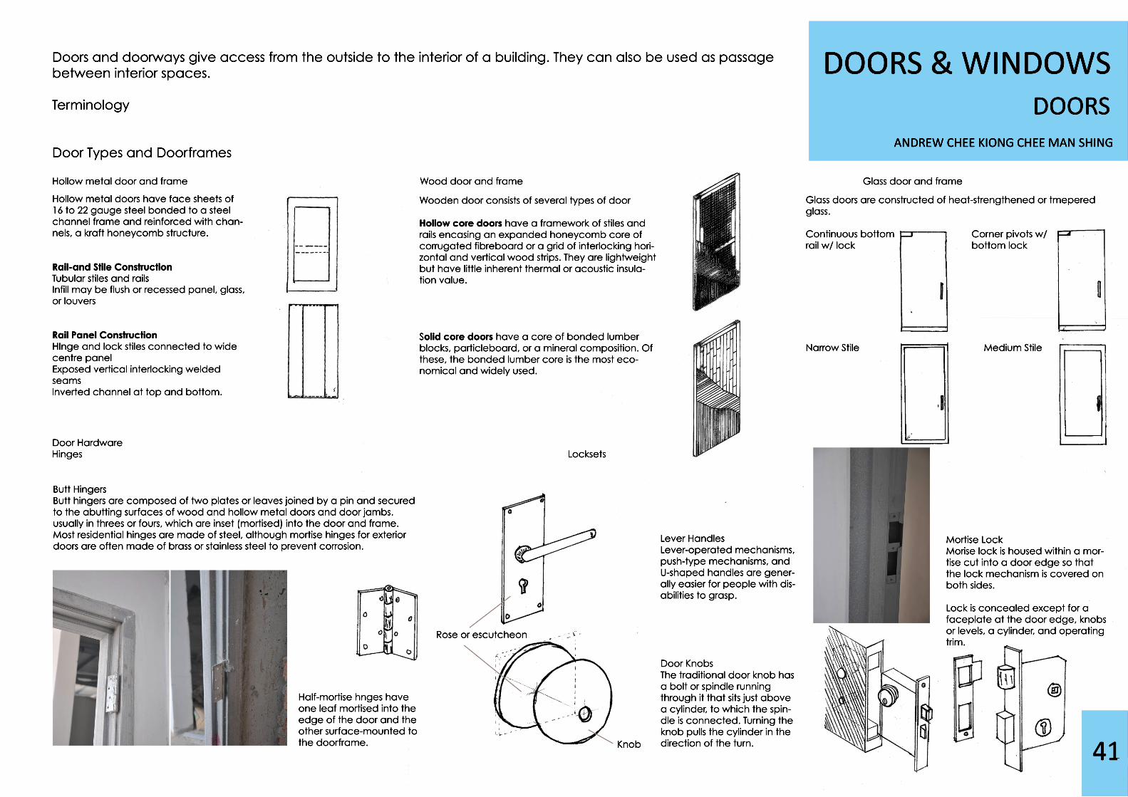
Doors and doorways give access from the outside to the interior of a building. They can also be used as passage between interior spaces.
Terminology
Door Types and Doorframes
Hollow metal door and frame Wood door and frame Glass door and frame
Door HardwareHingesHinges Locksets
Hollow metal doors have face sheets of 16 to 22 gauge steel bonded to a steel channel frame and reinforced with chan-nels, a kraft honeycomb structure.
Rail-and Stile ConstructionTubular stiles and railsInfill may be flush or recessed panel, glass, or louvers
Rail Panel ConstructionHInge and lock stiles connected to wide centre panelExposed vertical interlocking welded seamsInverted channel at top and bottom.Inverted channel at top and bottom.
Wooden door consists of several types of door
Hollow core doorsHollow core doors have a framework of stiles and rails encasing an expanded honeycomb core of corrugated fibreboard or a grid of interlocking hori-zontal and vertical wood strips. They are lightweight but have little inherent thermal or acoustic insula-tion value.
Solid core doors have a core of bonded lumber blocks, particleboard, or a mineral composition. Of these, the bonded lumber core is the most eco-nomical and widely used.
Glass doors are constructed of heat-strengthened or tmepered glass.
Continuous bottom Corner pivots w/ rail w/ lock bottom lock
Narrow Stile Medium Stile
Mortise LockMorise lock is housed within a mor-tise cut into a door edge so that the lock mechanism is covered on both sides.
Lock is concealed except for a faceplate at the door edge, knobs or levels, a cylinder, and operating trim.
Butt HingersButt hingers are composed of two plates or leaves joined by a pin and secured to the abutting surfaces of wood and hollow metal doors and door jambs.usually in threes or fours, which are inset (mortised) into the door and frame. Most residential hinges are made of steel, although mortise hinges for exterior doors are often made of brass or stainless steel to prevent corrosion.
Lever HandlesLever-operated mechanisms, push-type mechanisms, and U-shaped handles are gener-ally easier for people with dis-abilities to grasp.
Door KnobsThe traditional door knob has The traditional door knob has a bolt or spindle running through it that sits just above a cylinder, to which the spin-dle is connected. Turning the knob pulls the cylinder in the direction of the turn. Knob
Rose or escutcheon
Half-mortise hnges have one leaf mortised into the edge of the door and the other surface-mounted to the doorframe.
ANDREW CHEE KIONG CHEE MAN SHING
DOORS & WINDOWSDOORS
42
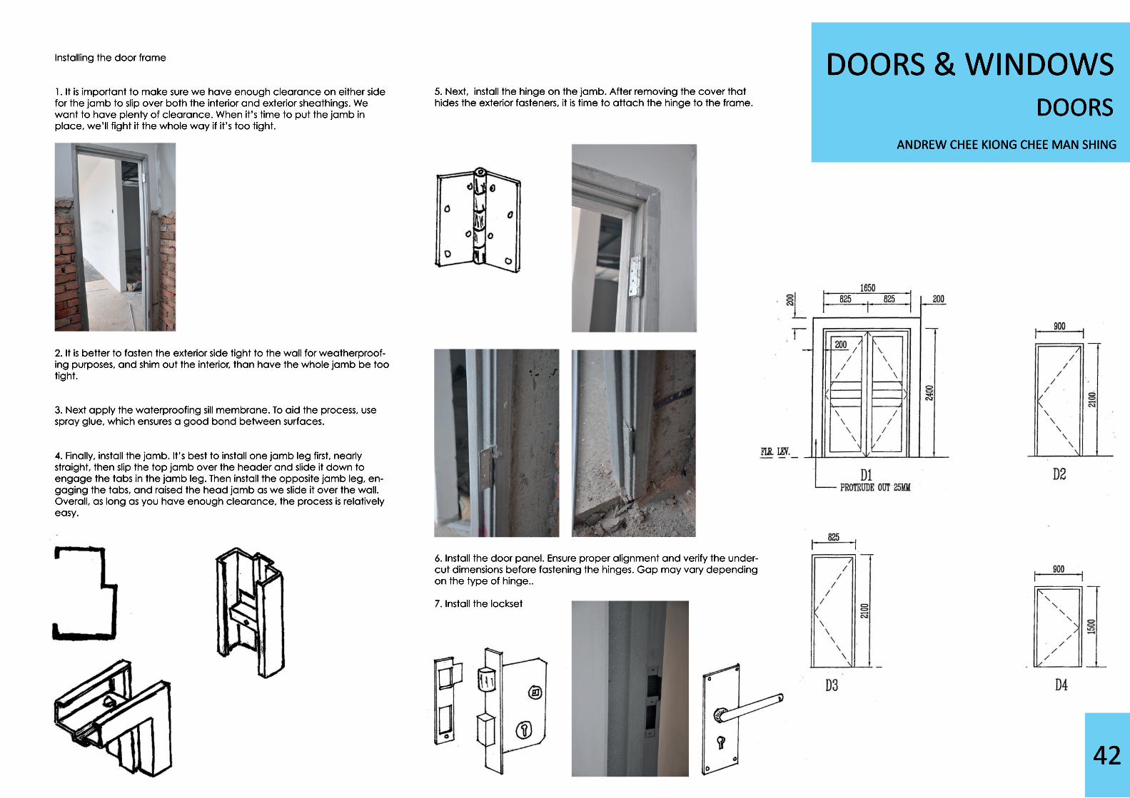
Installing the door frame
1. It is important to make sure we have enough clearance on either side for the jamb to slip over both the interior and exterior sheathings. We want to have plenty of clearance. When it’s time to put the jamb in place, we’ll fight it the whole way if it’s too tight.
2. It is better to fasten the exterior side tight to the wall for weatherp2. It is better to fasten the exterior side tight to the wall for weatherproof-ing purposes, and shim out the interior, than have the whole jamb be too tight.
3. Next apply the waterproofing sill membrane. To aid the process, use spray glue, which ensures a good bond between surfaces.
4. Finally, install the jamb. It’s best to install one jamb leg first, nearly straight, then slip the top jamb over the header and slide it down to engage the tabs in the jamb leg. Then install the opposite jamb leg, en-gaging the tabs, and raised the head jamb as we slide it over the wall. Overall, as long as you have enough clearance, the process is relatively easy.
5. Next, install the hinge on the jamb. After removing the cover that hides the exterior fasteners, it is time to attach the hinge to the frame.
6. Install the door panel. Ensure proper alignment and verify the under-cut dimensions before fastening the hinges. Gap may vary depending on the type of hinge..
7. Install the lockset

ANDREW CHEE KIONG CHEE MAN SHING
DOORS & WINDOWSDOORS
43
Installing the sliding door
1. At the same time that the wall is being erected, install the sub-frame for normal sliding door.
2. Install the door panel and ironmongery.
3. Check and ensure the door panel is without defects. Check visually for any surface damage before installation.
4. Fix the i4. Fix the ironmongery onto the door panel. Check if the correct ironmongeries are being used. After fixing, test the functionality of the door, by opening and closing it.
5. Install the main frame and the architrave. Install the vertical frames first, then finish the architrave by adding the horizontal part.
Safety Precautions
1. One of the prior step of the construction is to ensure that the vertical parts of the frames are firmly secured before in-staling the horizontal part of the frame as the horizontal part of the frame may cause the swaying of the vertucal parts.
2. Ensure a consistent gap between the panel and frame to ensure smooth operation of the door.
ANDREW CHEE KIONG CHEE MAN SHING
DOORS & WINDOWSWINDOWS
44
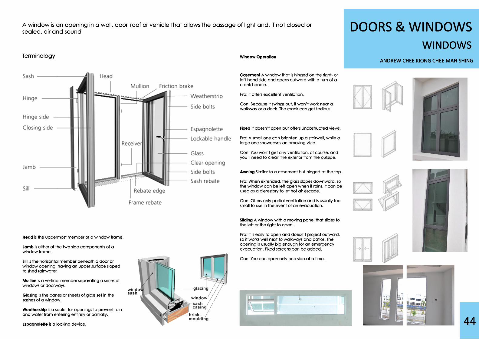
A window is an opening in a wall, door, roof or vehicle that allows the passage of light and, if not closed or sealed, air and sound
Terminology
Head is the uppermost member of a window frame.
Jamb is either of the two side components of a window frame.
Sill is the horizontal member beneath a door or window opening, having an upper surface sloped to shed rainwater.
Mullion Mullion is a vertical member separating a series of windows or doorways.
Glazing is the panes or sheets of glass set in the sashes of a window.
Weatherstrip is a sealer for openings to prevent rain and water from entering entirely or partially.
Espagnolette is a locking device.
Window Operation
Casement A window that is hinged on the right- or left-hand side and opens outward with a turn of a crank handle.
Pro: It offers excellent ventilation.
Con: Because it swings out, it won’t work near a walkway or a deck. The crank can get tedious.
Fixed It doesn’t open but offers unobstructed views.
PPro: A small one can brighten up a stairwell, while a large one showcases an amazing vista.
Con: You won’t get any ventilation, of course, and you’ll need to clean the exterior from the outside.
Awning Similar to a casement but hinged at the top.
PPro: When extended, the glass slopes downward, so the window can be left open when it rains. It can be used as a clerestory to let hot air escape.
Con: Offers only partial ventilation and is usually too small to use in the event of an evacuation.
Sliding A window with a moving panel that slides to the left or the right to open.
PPro: It is easy to open and doesn’t project outward, so it works well next to walkways and patios. The opening is usually big enough for an emergency evacuation. Fixed screens can be added.
Con: You can open only one side at a time.
ANDREW CHEE KIONG CHEE MAN SHING
DOORS & WINDOWSWINDOWS
45
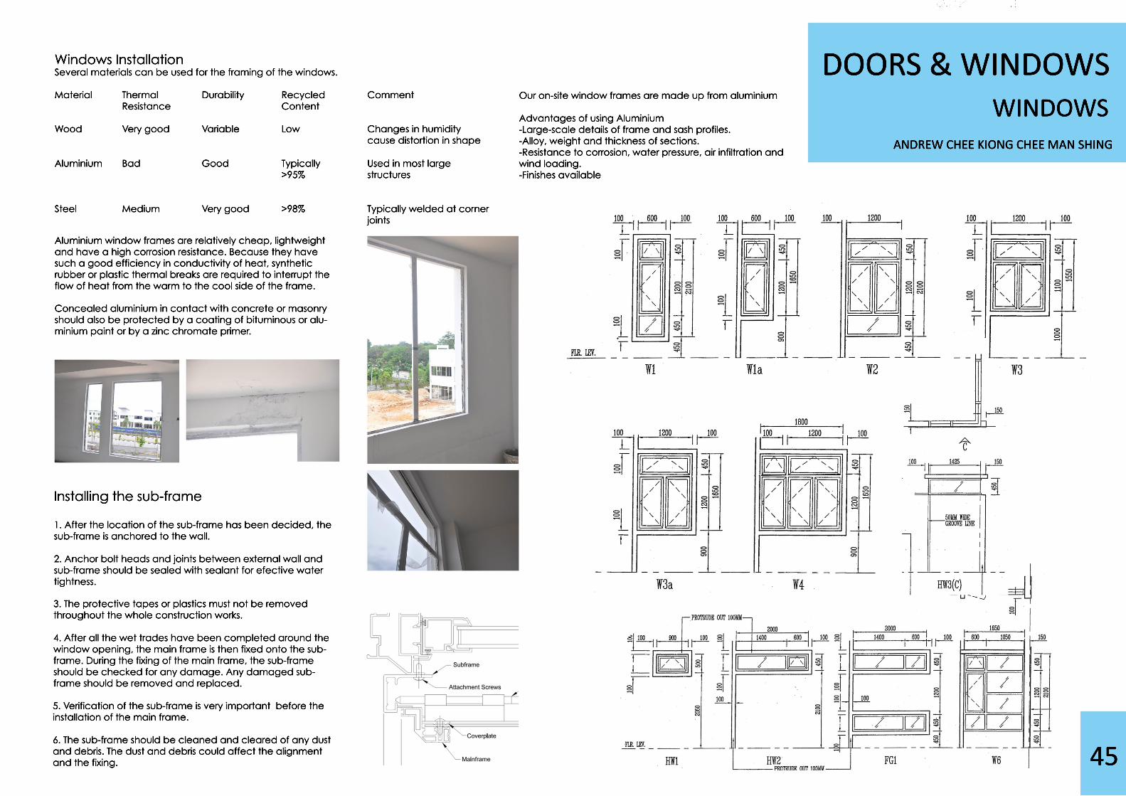
Windows InstallationSeveral materials can be used for the framing of the windows.
Material Thermal Durability Recycled Comment Resistance Content
Wood Very good Variable Low Changes in humidity cause distortion in shape
AluminiumAluminium Bad Good Typically Used in most large >95% structures
Steel Medium Very good >98% Typically welded at corner joints
Installing the sub-frame
1. After the location of the sub-frame has been decided, the sub-frame is anchored to the wall.
2. Anchor bolt heads and joints between external wall and sub-frame should be sealed with sealant for efective water tightness.
3. The p3. The protective tapes or plastics must not be removed throughout the whole construction works.
4. After all the wet trades have been completed around the window opening, the main frame is then fixed onto the sub-frame. During the fixing of the main frame, the sub-frame should be checked for any damage. Any damaged sub-frame should be removed and replaced.
5. Verification of the sub-frame is very important before the installation of the main frame.
6. The sub-frame should be cleaned and cleared of any dust and debris. The dust and debris could affect the alignment and the fixing.
Our on-site window frames are made up from aluminium
Advantages of using Aluminium-Large-scale details of frame and sash profiles.-Alloy, weight and thickness of sections.-Resistance to corrosion, water pressure, air infiltration and wind loading.-Finishes available-Finishes available
Aluminium window frames are relatively cheap, lightweight and have a high corrosion resistance. Because they have such a good efficiency in conductivity of heat, synthetic rubber or plastic thermal breaks are required to interrupt the flow of heat from the warm to the cool side of the frame.
Concealed aluminium in contact with concConcealed aluminium in contact with concrete or masonry should also be protected by a coating of bituminous or alu-minium paint or by a zinc chromate primer.
ANDREW CHEE KIONG CHEE MAN SHING
DOORS & WINDOWSWINDOWS
46
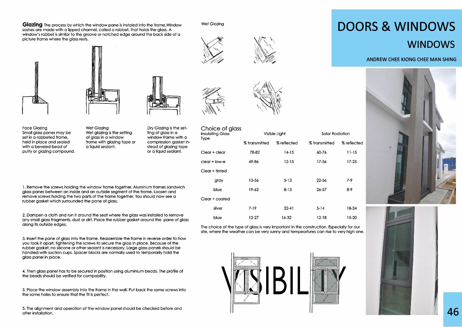
Face GlazingSmall glass panes may be set in a rabbeted frame, held in place and sealed with a beveled bead of putty or glazing compound.
Wet GlazingWet glazing is the setting of glass in a window frame with glazing tape or a liquid sealant.
1. Remove the screws holding the window frame together. Aluminum frames sandwich glass panes between an inside and an outside segment of the frame. Loosen and remove screws holding the two parts of the frame together. You should now see a rubber gasket which surrounded the pane of glass.
2. Dampen a cloth and run it around the seat where the glass was installed to remove any small glass fragments, dust or dirt. Place the rubber gasket around the pane of glass along its outside edges.
3. Insert the pane of glass into the frame. Reassemble the frame in 3. Insert the pane of glass into the frame. Reassemble the frame in reverse order to how you took it apart, tightening the screws to secure the glass in place. Because of the rubber gasket, no silicone or other sealant is necessary. Large glass panels should be handled with suction cups. Spacer blocks are normally used to temporarily hold the glass panel in place.
4. Then glass panel has to be secured in position using aluminium beads. The profile of the beads should be verified for compability.
5. Place the window assembly into the frame in the wall. Put back the same sc5. Place the window assembly into the frame in the wall. Put back the same screws into the same holes to ensure that the fit is perfect.
5. The alignment and operation of the window panel should be checked before and after installation.
Choice of glassInsulating Glass Visible Light Solar RadiationType % transmitted % reflected % transmitted % reflected
Clear + clear 78-82 14-15 60-76 11-15
clear + low-e 49-86 12-15 17-56 17-25
Clear + tintedClear + tinted
gray 13-56 5-13 22-56 7-9
blue 19-62 8-13 26-57 8-9
Clear + coated
silver 7-19 22-41 5-14 18-34
blue 12-27 16-32 12-18 15-20
The choice of the type of glass is very important in the construction. Especially for our The choice of the type of glass is very important in the construction. Especially for our site, where the weather can be very sunny and tempeartures can rise to very high one.
Wet Glazing
Dry Glazing is the set-ting of glass in a window frame with a compression gasket in-stead of glazing tape or a liquid sealant.
Glazing The process by which the window pane is instaled into the frame.Window sashes are made with a lipped channel, called a rabbet, that holds the glass. A window’s rabbet is similar to the groove or notched edge around the back side of a picture frame where the glass rests.
VISIBILITYVISIBILITY

47
BY LIM JIAN JUN
ROOFTYPES OF ROOF
48
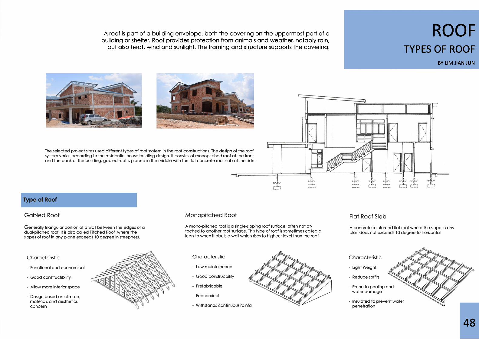
A roof is part of a building envelope, both the covering on the uppermost part of a building or shelter. Roof provides protection from animals and weather, notably rain, but also heat, wind and sunlight. The framing and structure supports the covering.
Monopitched Roof
A mono-pitched roof is a single-sloping roof surface, often not at-tached to another roof surface. This type of roof is sometimes called a lean-to when it abuts a wall which rises to higheer level than the roof
Flat Roof Slab
A concrete reinforced flat roof where the slope in any plan does not exceeds 10 degree to horizontal
Characteristic
- Functional and economical
- Good constructibility
- Allow more interior space
- Design based on climate, materials and aesthetics conce concern
Characteristic
- Light Weight
- Reduce soffits
- Prone to pooling and water damage
- Insulated to prevent water penetration penetration
Characteristic
- Low maintainence
- Good construcbility
- Prefabricable
- Economical
- Withstands continuous rainfall
Gabled Roof
Generally triangular portion of a wall between the edges of a dual-pitched roof. It is also called Pitched Roof where the slopes of roof in any plane exceeds 10 degree in steepness.
The selected project sites used different types of roof system in the roof constructions. The design of the roof system varies according to the residential house buidling design. It consists of monopitched roof at the front and the back of the building, gabled roof is placed in the middle with the flat concrete roof slab at the side.
Type of Roof
BY LIM JIAN JUN
ROOFCONSTRUCTION DETAILS
49
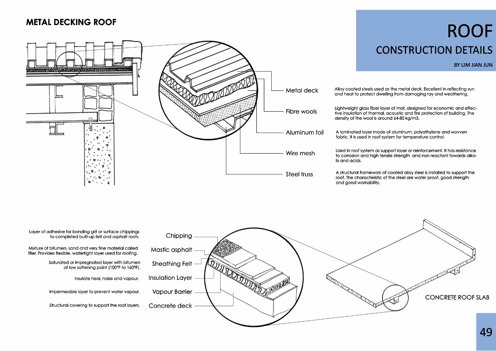
CONCRETE ROOF SLAB
Chipping
Mastic asphalt
Sheathing Felt
Insulation Layer
Vapour Barrier
Concrete deck
Mixture of bitumen, sand and very fine material called filler. Provides flexible, watertight layer used for roofing.
Saturated or impregnated layer with bitumen of low softening point (100°F to 160°F).
Insulate hear, noise and vapour.
Impermeable layer to prevent water vapour.
Structural covering to support the roof layers.
Layer of adhesive for bonding grit or surface chippings to completed built-up felt and asphalt roofs.
Metal deck
Fibre wools
Aluminum foil
WWire mesh Steel truss
Alloy coated steels used as the metal deck. Excellent in reflecting sun and heat to protect dwelling from damaging ray and weathering.
A laminated layer made of aluminum, polyathylene and wovven fabric. It is used in roof system for temperature control.
Used in roof system as support layer or reinforcement. It has resistance to corrosion and high tensile strength and non reactant towards alka-lis and acids.
A structural framework of coated alloy steel is installed to support the roof. The characteristic of the steel are water proof, good strength and good workability.
Lightweight glass fiber layer of mat, designed for economic and effec-tive insulation of thermal, acoustic and fire protection of building, The density of the wool is around 64-80 kg/m3.
METAL DECKING ROOF
BY LIM JIAN JUN
ROOFCONSTRUCTION DETAILS
50
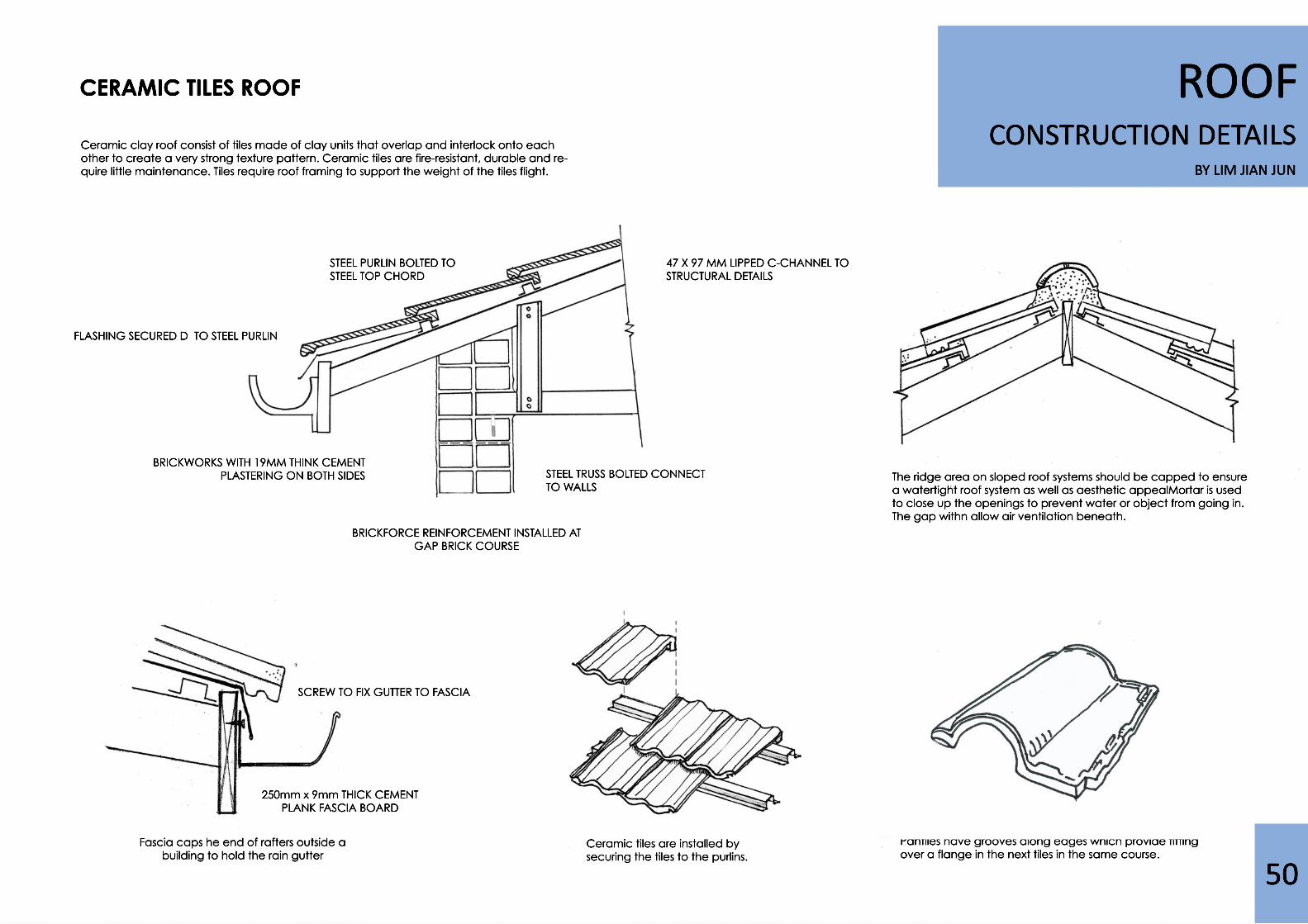
STEEL PURLIN BOLTED TO STEEL TOP CHORD
STEEL TRUSS BOLTED CONNECT TO WALLS
47 X 97 MM LIPPED C-CHANNEL TO STRUCTURAL DETAILS
FLASHING SECURED D TO STEEL PURLIN
BRICKWORKS WITH 19MM THINK CEMENT PLASTERING ON BOTH SIDES
BRICKFORCE REINFORCEMENT INSTALLED AT GAP BRICK COURSE
CERAMIC TILES ROOF
250mm x 9mm THICK CEMENT PLANK FASCIA BOARD
SCREW TO FIX GUTTER TO FASCIA
Pantiles have grooves along edges which provide fitting over a flange in the next tiles in the same course.
The ridge area on sloped roof systems should be capped to ensure a watertight roof system as well as aesthetic appealMortar is used to close up the openings to prevent water or object from going in. The gap withn allow air ventilation beneath.
Ceramic tiles are installed by securing the tiles to the purlins.
Fascia caps he end of rafters outside a building to hold the rain gutter
Ceramic clay roof consist of tiles made of clay units that overlap and interlock onto each other to create a very strong texture pattern. Ceramic tiles are fire-resistant, durable and re-quire little maintenance. Tiles require roof framing to support the weight of the tiles flight.
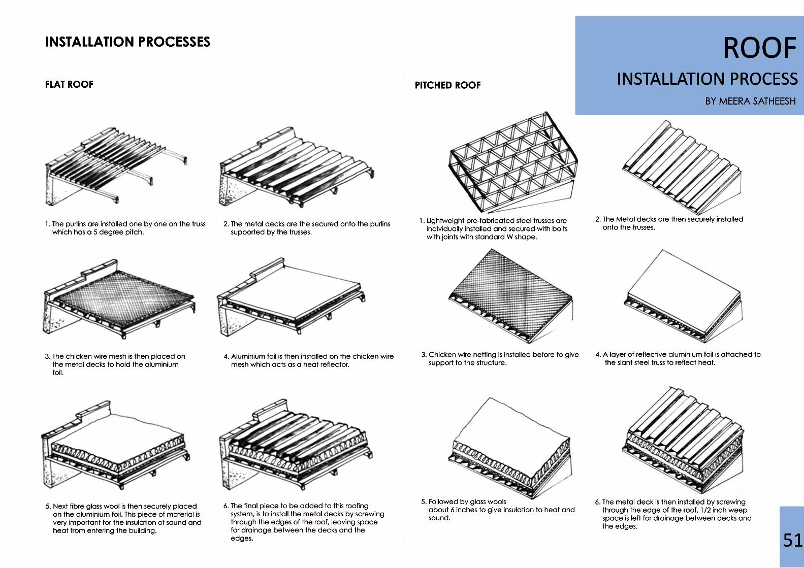
ROOFINSTALLATION PROCESS
INSTALLATION PROCESSES
PITCHED ROOFFLAT ROOF
6. The metal deck is then installed by screwing through the edge of the roof, 1/2 inch weep space is left for drainage between decks and the edges.
4. A layer of reflective aluminium foil is attached to the slant steel truss to reflect heat.
2. The Metal decks are then securely installed onto the trusses.
5. Followed by glass wools about 6 inches to give insulation to heat and sound.
3. Chicken wire netting is installed before to give support to the structure.
1. Lightweight pre-fabricated steel trusses are individually installed and secured with bolts with joints with standard W shape.
6. The final piece to be added to this roofing system, is to install the metal decks by screwing through the edges of the roof, leaving space for drainage between the decks and the edges.
5. Next fibre glass wool is then securely placed on the aluminium foil. This piece of material is very important for the insulation of sound and heat from entering the building.
BY MEERA SATHEESH
51
4. Aluminium foil is then installed on the chicken wire mesh which acts as a heat reflector.
3. The chicken wire mesh is then placed on the metal decks to hold the aluminium foil.
2. The metal decks are the secured onto the purlins supported by the trusses.
1. The purlins are installed one by one on the truss which has a 5 degree pitch.

by LIM JIAN JUN
ROOFCONSTRUCTION DETAILS
52Steel plate bracket fixed truss onto wall. Cement is then used to cover up the uneven surface.
JOINTS AND CONNECTIONS
Truss is secured to the gusset plate for greater support
Truss is bolted with bracket andanchor bolt is fixed into the wall
Rafters and channel purlins are fixed using self fastening bolts
PITCH = RISE / SPAN
RISE
SPAN
RUN
Mechanical service such as piping , conduit and ductwork is arrange and fixed to the truss through the web spaces.
Bricks are laid on beam as pediment after roof structure is fixed
CHANNEL PURLINS SPAN THE TRUSS SPACING
TYPICAL STEEL ROOF TRUSS FRAMEWORK DETAILS
Steel truss generally fabricated by welding and bolting structural angles and tees together to form the triangu-lated framework. Due to the slenderness of these truss members, connections usually require the use of steel gusset plates or plainly bolted with bolts.
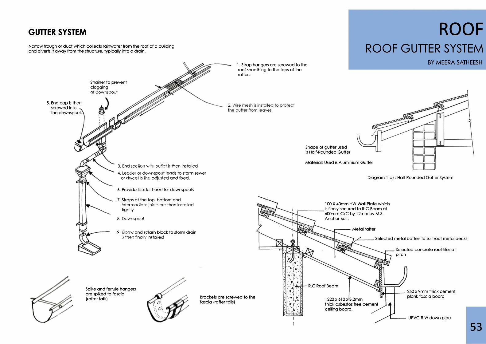
Spike and ferrule hangersare spiked to fascia (rafter tails) Brackets are screwed to the
fascia (rafter tails)
Diagram 1(a) : Half-Rounded Gutter System
Shape of gutter usedis Half-Rounded Gutter
Materials Used is Aluminium Gutter
ROOF GUTTER SYSTEM
ROOFBY MEERA SATHEESH
53
GUTTER SYSTEM
100 X 40mm HW Wall Plate which is firmly secured to R.C Beam at 600mm C/C by 12mm by M.S. Anchor Bolt.
Metal rafter
Selected metal batten to suit roof metal decks
Selected concrete roof tiles at pitch
250 x 9mm thick cement plank fascia board
UPVC R.W down pipe
R.C Roof Beam
1220 x 610 x 3.2mm thick asbestos free cementceiling board.
Narrow trough or duct which collects rainwater from the roof of a building and diverts it away from the structure, typically into a drain.
1. Strap hangers are screwed to the roof sheathing to the tops of the rafters.
Strainer to prevent cloggingof downspout
5. End cap is then screwed into the downspout.
3. End section with outlet is then installed
4. Leader or downspout leads to storm sewer or drycell is the adjusted and fixed.
7. Straps at the top, bottom and intermediate joints are then installed tightly
8. Downspout
9. Elbow and splash block to storm drain is then finally installed
6. Provide leader head for downspouts
Through this real life experiential learning project, we have developed our understanding of the principles, sequence of construction activities, impor-tance of basic detailing, construction joints and material application. We are exposed to construction technology and methods responding to site con-text and have undergone a series of continuous assessments, site visits, discussions and presentation. Through the analysis and documentation that we have done, we understand and are able to explain the construction elements, its components, sequence and coordination of construction at site.
In this project, we are encouraged to be genuinely curious about the people we are working with, such as teammates and construction workers: e.g., what they think, what they want, what they do. Rather than coming in as an expert with the answers, we can come in with a spirit of curiosity where we hope to learn together as well. In the end of this project, each of us gets to learn many things or at least having a rough idea of how the other parts of the buildings are constructed.
WWe also observed that not every aspect meets the requirement: e.g., safety rebar cap are not being used and materials are not placed carefully due to varies reason such as costs and site management. Despite of all these reasons, we should have followed the rules as they provide us more safety and safety always is the most important.
54
1. FRANCIS D.K. CHING, BUILDING CONSTRUCTION ILLUSTRATED, Fourth Edition, United State, John Wiley & Sons, INC, 2008.
2. C.N. MINDHAM, ROOF CONSTRUCTION AND LOFT CONVERSION, Fourth Edition, United Kingdom, BlackWell Publishing, 2000.
3. CHARLES GEORGE RAMSEY, CONSTRUCTION DETAILS, English Edition, United State, The American Institute of Architects, 2004.
4. BRIAN COOKE, CONSTRUCTION PLANNING, PROGRAMMING AND CONTROL, United State, Wiley and Blackwell, 2009.
5. DAM RAMSEY, BUILDERS GUIDES TO FOUNDATIONS AND FLOOR FRAMING, United State, McGaw Hill, 1995.
5. Hoarding. (2010). WikiAnswers. Retrieved May 15, 2014, from http://wiki.answers.com/Q/Is_the_te http://wiki.answers.com/Q/Is_the_term_construction_hoarding_referring_to_temporary_fencing_around_a_construction_site_still_in_use?#slide=12
6. Site Office. (n.d.). Site Offices. Retrieved May 15, 2014, from http://www.portacom.co.nz/site-office.htm
7. Hoarding. (2010). WikiAnswers. Retrieved May 15, 2014, from http://wiki.answers.com/Q/Is_the_term_construction_hoarding_referring_to_temporary_fencing_around_a_construction_site_still_in_use?#slide=12
8. Site Office. (n.d.). Site Offices. Retrieved May 15, 2014, from http://www.portacom.co.nz/site-office.htm
9 Setting Out Procedure. (n.d.). . Retrieved May 15, 2014, from http://lea http://learning.covcollege.ac.uk/content/CITB%20Craft%20Information%20Sheets/BW/materials/Sec05-Setting%20Out/Sec05-M04.pdf
8. C.R. Asfahl, Industrial Safety and Health Management, 5th ed. Upper Saddle River, NJ: Prentice Hall, 2004.
55