· Web viewWALL CONSTRUCTION WALL CONSTRUCTION WALL CONSTRUCTION WALL CONSTRUCTION WALL...
450
Florida Supplement to the 2012 IRC PRE-GLITCH CORRECTION VERSION Note 1: Throughout the document, change International Building Code to Florida Building Code, Building; change the ICC Electrical Code to Chapter 27 of the Florida Building Code, Building; change the International Energy Conservation Code to the Florida Building Code, Energy Conservation; change the International Existing Building Code to Florida Building Code, Existing Building; change the International Fire code to Florida Fire Prevention Code; change International Fuel Gas Code to Florida Building Code, Fuel Gas; change the International Mechanical Code to Florida Building Code, Mechanical; change the International Plumbing Code to Florida Building Code, Plumbing; change the International Residential Code to Florida Building Code, Residential. CHAPTER 1, SCOPE AND ADMINISTRATION Section R101.2 Scope. Change to read as follows: R101.2 Scope. The provisions of the Florida Building Code, Residential, shall apply to the construction, alteration, movement, enlargement, replacement, repair, equipment, use and occupancy, location, removal and demolition of detached one– and two–family dwellings and (townhouses) not more than three stories above grade plane in height with a separate means of egress and their accessory structures. Exceptions: 1-2 No change 3. Existing buildings undergoing repair, alteration or additions, and change of occupancy shall comply with the Florida Building Code , Existing Building.. WALL CONSTRUCTION FLORIDA BUILDING CODE — RESIDENTIAL 7.1
Transcript of · Web viewWALL CONSTRUCTION WALL CONSTRUCTION WALL CONSTRUCTION WALL CONSTRUCTION WALL...
Florida Supplement to the 2012 IRCPRE-GLITCH CORRECTION VERSION
Note 1: Throughout the document, change International Building Code to Florida Building Code, Building; change the ICC Electrical Code to Chapter 27 of the Florida Building Code, Building; change the International Energy Conservation Code to the Florida Building Code, Energy Conservation; change the International Existing Building Code to Florida Building Code, Existing Building; change the International Fire code to Florida Fire Prevention Code; change International Fuel Gas Code to Florida Building Code, Fuel Gas; change the International Mechanical Code to Florida Building Code, Mechanical; change the International Plumbing Code to Florida Building Code, Plumbing; change the International Residential Code to Florida Building Code, Residential.
CHAPTER 1, SCOPE AND ADMINISTRATION
Section R101.2 Scope. Change to read as follows:
R101.2 Scope. The provisions of the Florida Building Code, Residential, shall apply to the construction, alteration, movement, enlargement, replacement, repair, equipment, use and occupancy, location, removal and demolition of detached one– and two–family dwellings and (townhouses) not more than three stories above grade plane in height with a separate means of egress and their accessory structures.
Exceptions:
1-2 No change
3. Existing buildings undergoing repair, alteration or additions, and change of occupancy shall comply with the Florida Building Code, Existing Building..
R101.2.1 The provisions of Chapter 1, Florida Building Code, Building, shall govern the administration and enforcement of the Florida Building Code, Residential.
Section R101.3 Intent. Change to read as follows:
R101.3 Intent. The purpose of this code is to establish minimum requirements to safeguard the public safety, health and general welfare through affordability, structural strength, means of egress facilities, stability, sanitation, light and ventilation, energy conservation and safety to life and property from fire and other hazards attributed to the built environment and to provide safety to fire fighters and emergency responders during emergency operations. Reserved.
WALL CONSTRUCTION
FLORIDA BUILDING CODE — RESIDENTIAL 7.1
Sections R102 through R114. Change to read as follows:
SECTION R102 APPLICABILITY
RESERVED
R102.1 General. Where there is a conflict between a general requirement and a specific requirement, the specific requirement shall be applicable. Where, in any specific case, different sections of this code specify different materials, methods of construction or other requirements, the most restrictive shall govern.
R102.2 Other laws. The provisions of this code shall not be deemed to nullify any provisions of local, state or federal law.
R102.3 Application of references. References to chapter or section numbers, or to provisions not specifically identified by number, shall be construed to refer to such chapter, section or provision of this code.
R102.4 Referenced codes and standards. The codes and standards referenced in this code shall be considered part of the requirements of this code to the prescribed extent of each such reference and as further regulated in Sections R102.4.1 and R102.4.2. Exception: Where enforcement of a code provision would violate the conditions of the listing of the equipment or appliance, the conditions of the listing and manufacturer’s instructions shall apply.
R102.4.1 Differences. Where differences occur between provisions of this code and referenced codes and standards, the provisions of this code shall apply.
R102.4.2 Provisions in referenced codes and standards. Where the extent of the reference to a referenced code or standard includes subject matter that is within the scope of this code, the provisions of this code, as applicable, shall take precedence over the provisions in the referenced code or standard.
R102.5 Appendices. Provisions in the appendices shall not apply unless specifically referenced in the adopting ordinance.
R102.6 Partial invalidity. In the event any part or provision of this code is held to be illegal or void, this shall not have the effect of making void or illegal any of the other parts or provisions.
R102.7 Existing structures. The legal occupancy of any structure existing on the date of adoption of this code shall be permitted to continue without change, except as is specifically covered in this code, the International Property Maintenance Code or the International Fire
WALL CONSTRUCTION
FLORIDA BUILDING CODE — RESIDENTIAL 7.2
Code, or as is deemed necessary by the building official for the general safety and welfare of the occupants and the public.
R102.7.1 Additions, alterations or repairs. Additions, alterations or repairs to any structure shall conform to the requirements for a new structure without requiring the existing structure to comply with all of the requirements of this code, unless otherwise stated. Additions, alterations or repairs shall not cause an existing structure to become unsafe or adversely affect the performance of the building.
SECTION R103DEPARTMENT OF BUILDING SAFETY
RESERVED
R103.1 Creation of enforcement agency. The department of building safety is hereby created and the official in charge thereof shall be known as the building official.
R103.2 Appointment. The building official shall be appointed by the chief appointing authority of the jurisdiction.
R103.3 Deputies. In accordance with the prescribed procedures of this jurisdiction and with the concurrence of the appointing authority, the building official shall have the authority to appoint a deputy building official, the related technical officers, inspectors, plan examiners and other employees. Such employees shall have powers as delegated by the building official.
SECTION R104DUTIES AND POWERS OF THE BUILDING OFFICIAL
RESERVED
R104.1 General. The building official is hereby authorized and directed to enforce the provisions of this code. The building official shall have the authority to render interpretations of this code and to adopt policies and procedures in order to clarify the application of its provisions. Such interpretations, policies and procedures shall be in conformance with the intent and purpose of this code. Such policies and procedures shall not have the effect of waiving requirements specifically provided for in this code.
R104.2 Applications and permits. The building official shall receive applications, review construction documents and issue permits for the erection and alteration of buildings and structures, inspect the premises for which such permits have been issued and enforce compliance with the provisions of this code.
R104.3 Notices and orders. The building official shall issue all necessary notices or orders to ensure compliance with this code.
WALL CONSTRUCTION
FLORIDA BUILDING CODE — RESIDENTIAL 7.3
R104.4 Inspections. The building official is authorized to make all of the required inspections, or the building official shall have the authority to accept reports of inspection by approved agencies or individuals. Reports of such inspections shall be in writing and be certified by a responsible officer of such approved agency or by the responsible individual. The building official is authorized to engage such expert opinion as deemed necessary to report upon unusual technical issues that arise, subject to the approval of the appointing authority.
R104.5 Identification. The building official shall carry proper identification when inspecting structures or premises in the performance of duties under this code.
R104.6 Right of entry. Where it is necessary to make an inspection to enforce the provisions of this code, or where the building official has reasonable cause to believe that there exists in a structure or upon a premises a condition which is contrary to or in violation of this code which makes the structure or premises unsafe, dangerous or hazardous, the building official or designee is authorized to enter the structure or premises at reasonable times to inspect or to perform the duties imposed by this code, provided that if such structure or premises be occupied that credentials be presented to the occupant and entry requested. If such structure or premises be unoccupied, the building official shall first make a reasonable effort to locate the owner or other person having charge or control of the structure or premises and request entry. If entry is refused, the building official shall have recourse to the remedies provided by law to secure entry.
R104.7 Department records. The building official shall keep official records of applications received, permits and certificates issued, fees collected, reports of inspections, and notices and orders issued. Such records shall be retained in the official records for the period required for the retention of public records.
R104.8 Liability. The building official, member of the board of appeals or employee charged with the enforcement of this code, while acting for the jurisdiction in good faith and without malice in the discharge of the duties required by this code or other pertinent law or ordinance, shall not thereby be rendered liable personally and is hereby relieved from personal liability for any damage accruing to persons or property as a result of any act or by reason of an act or omission in the discharge of official duties. Any suit instituted against an officer or employee because of an act performed by that officer or employee in the lawful discharge of duties and under the provisions of this code shall be defended by legal representative of the jurisdiction until the final termination of the proceedings. The building official or any subordinate shall not be liable for cost in any action, suit or proceeding that is instituted in pursuance of the provisions of this code.
R104.9 Approved materials and equipment. Materials, equipment and devices approved by the building official shall be constructed and installed in accordance with such approval.
R104.9.1 Used materials and equipment. Used materials, equipment and devices shall not be reused unless approved by the building official.
R104.10 Modifications. Wherever there are practical difficulties involved in carrying out the provisions of this code, the building official shall have the authority to grant modifications for
WALL CONSTRUCTION
FLORIDA BUILDING CODE — RESIDENTIAL 7.4
individual cases, provided the building official shall first find that special individual reason makes the strict letter of this code impractical and the modification is in compliance with the intent and purpose of this code and that such modification does not lessen health, life and fire safety or structural requirements. The details of action granting modifications shall be recorded and entered in the files of the department of building safety.
R104.10.1 Flood hazard areas. The building official shall not grant modifications to any provision related to flood hazard areas as established by Table R301.2(1) without the granting of a variance to such provisions by the board of appeals.
R104.11 Alternative materials, design and methods of construction and equipment. The provisions of this code are not intended to prevent the installation of any material or to prohibit any design or method of construction not specifically prescribed by this code, provided that any such alternative has been approved. An alternative material, design or method of construction shall be approved where the building official finds that the proposed design is satisfactory and complies with the intent of the provisions of this code, and that the material, method or work offered is, for the purpose intended, at least the equivalent of that prescribed in this code. Compliance with the specific performance-based provisions of the International Codes in lieu of specific requirements of this code shall also be permitted as an alternate.
R104.11.1 Tests. Whenever there is insufficient evidence of compliance with the provisions of this code, or evidence that a material or method does not conform to the requirements of this code, or in order to substantiate claims for alternative materials or methods, the building official shall have the authority to require tests as evidence of compliance to be made at no expense to the jurisdiction. Test methods shall be as specified in this code or by other recognized test standards. In the absence of recognized and accepted test methods, the building official shall approve the testing procedures. Tests shall be performed by an approved agency. Reports of such tests shall be retained by the building official for the period required for retention of public records.
SECTION R105PERMITS
RESERVED
R105.1 Required. Any owner or authorized agent who intends to construct, enlarge, alter, repair, move, demolish or change the occupancy of a building or structure, or to erect, install, enlarge, alter, repair, remove, convert or replace any electrical, gas, mechanical or plumbing system, the installation of which is regulated by this code, or to cause any such work to be done, shall first make application to the building official and obtain the required permit.
R105.2 Work exempt from permit. Permits shall not be required for the following. Exemption from permit requirements of this code shall not be deemed to grant authorization for any work to be done in any manner in violation of the provisions of this code or any other laws or ordinances
WALL CONSTRUCTION
FLORIDA BUILDING CODE — RESIDENTIAL 7.5
of this jurisdiction.
Building:
1. One-story detached accessory structures used as tool and storage sheds, playhouses and similar uses, provided the floor area does not exceed 200 square feet (18.58 m2).
2. Fences not over 7 feet (2134 mm) high.
3. Retaining walls that are not over 4 feet (1219 mm) in height measured from the bottom of the footing to the top of the wall, unless supporting a surcharge.
4. Water tanks supported directly upon grade if the capacity does not exceed 5,000 gallons (18 927 L) and the ratio of height to diameter or width does not exceed 2 to 1.
5. Sidewalks and driveways.
6. Painting, papering, tiling, carpeting, cabinets, counter tops and similar finish work.
7. Prefabricated swimming pools that are less than 24 inches (610 mm) deep.
8. Swings and other playground equipment.
9. Window awnings supported by an exterior wall which do not project more than 54 inches (1372 mm) from the exterior wall and do not require additional support.
10. Decks not exceeding 200 square feet (18.58 m2) in area, that are not more than 30 inches (762 mm) above grade at any point, are not attached to a dwelling and do not serve the exit door required by Section R311.4.
Electrical:
1. Listed cord-and-plug connected temporary decorative lighting.
2. Reinstallation of attachment plug receptacles but not the outlets therefor.
3. Replacement of branch circuit overcurrent devices of the required capacity in the same location.
4. Electrical wiring, devices, appliances, apparatus or equipment operating at less than 25 volts and not capable of supplying more than 50 watts of energy.
5. Minor repair work, including the replacement of lamps or the connection of approved portable electrical equipment to approved permanently installed receptacles.
WALL CONSTRUCTION
FLORIDA BUILDING CODE — RESIDENTIAL 7.6
Gas:
1. Portable heating, cooking or clothes drying appliances.
2. Replacement of any minor part that does not alter approval of equipment or make such equipment unsafe.
3. Portable-fuel-cell appliances that are not connected to a fixed piping system and are not interconnected to a power grid.
Mechanical:
1. Portable heating appliances.
2. Portable ventilation appliances.
3. Portable cooling units.
4. Steam, hot- or chilled-water piping within any heating or cooling equipment regulated by this code.
5. Replacement of any minor part that does not alter approval of equipment or make such equipment unsafe.
6. Portable evaporative coolers.
7. Self-contained refrigeration systems containing 10 pounds (4.54 kg) or less of refrigerant or that are actuated by motors of 1 horsepower (746 W) or less.
8. Portable-fuel-cell appliances that are not connected to a fixed piping system and are not interconnected to a power grid.
The stopping of leaks in drains, water, soil, waste or vent pipe; provided, however, that if any concealed trap, drainpipe, water, soil, waste or vent pipe becomes defective and it becomes necessary to remove and replace the same with new material, such work shall be considered as new work and a permit shall be obtained and inspection made as provided in this code.
The clearing of stoppages or the repairing of leaks in pipes, valves or fixtures, and the removal and reinstallation of water closets, provided such repairs do not involve or require the replacement or rearrangement of valves, pipes or fixtures.
R105.2.1 Emergency repairs. Where equipment replacements and repairs must be performed in an emergency situation, the permit application shall be submitted within the next working business day to the building official.
WALL CONSTRUCTION
FLORIDA BUILDING CODE — RESIDENTIAL 7.7
R105.2.2 Repairs. Application or notice to the building official is not required for ordinary repairs to structures, replacement of lamps or the connection of approved portable electrical equipment to approved permanently installed receptacles. Such repairs shall not include the cutting away of any wall, partition or portion thereof, the removal or cutting of any structural beam or load-bearing support, or the removal or change of any required means of egress, or rearrangement of parts of a structure affecting the egress requirements; nor shall ordinary repairs include addition to, alteration of, replacement or relocation of any water supply, sewer, drainage, drain leader, gas, soil, waste, vent or similar piping, electric wiring or mechanical or other work affecting public health or general safety.
R105.2.3 Public service agencies. A permit shall not be required for the installation, alteration or repair of generation, transmission, distribution, metering or other related equipment that is under the ownership and control of public service agencies by established right.
R105.3 Application for permit. To obtain a permit, the applicant shall first file an application therefor in writing on a form furnished by the department of building safety for that purpose. Such application shall:
1. Identify and describe the work to be covered by the permit for which application is made.
2. Describe the land on which the proposed work is to be done by legal description, street address or similar description that will readily identify and definitely locate the proposed building or work.
3. Indicate the use and occupancy for which the proposed work is intended.
4. Be accompanied by construction documents and other information as required in Section R106.1.
5. State the valuation of the proposed work.
6. Be signed by the applicant or the applicant’s authorized agent.
7. Give such other data and information as required by the building official.
R105.3.1 Action on application. The building official shall examine or cause to be examined applications for permits and amendments thereto within a reasonable time after filing. If the application or the construction documents do not conform to the requirements of pertinent laws, the building official shall reject such application in writing stating the reasons therefor. If the building official is satisfied that the proposed work conforms to the requirements of this code and laws and ordinances applicable thereto, the building official shall issue a permit therefor as soon as practicable.
WALL CONSTRUCTION
FLORIDA BUILDING CODE — RESIDENTIAL 7.8

R105.3.1.1 Determination of substantially improved or substantially damaged existing buildings in flood hazard areas. For applications for reconstruction, rehabilitation, addition or other improvement of existing buildings or structures located in a flood hazard area as established by Table R301.2(1), the building official shall examine or cause to be examined the construction documents and shall prepare a finding with regard to the value of the proposed work. For buildings that have sustained damage of any origin, the value of the proposed work shall include the cost to repair the building or structure to its predamaged condition. If the building official finds that the value of proposed work equals or exceeds 50 percent of the market value of the building or structure before the damage has occurred or the improvement is started, the finding shall be provided to the board of appeals for a determination of substantial improvement or substantial damage. Applications determined by the board of appeals to constitute substantial improvement or substantial damage shall require all existing portions of the entire building or structure to meet the requirements of Section R322.
R105.3.2 Time limitation of application. An application for a permit for any proposed work shall be deemed to have been abandoned 180 days after the date of filing unless such application has been pursued in good faith or a permit has been issued; except that the building official is authorized to grant one or more extensions of time for additional periods not exceeding 180 days each. The extension shall be requested in writing and justifiable cause demonstrated.
R105.4 Validity of permit. The issuance or granting of a permit shall not be construed to be a permit for, or an approval of, any violation of any of the provisions of this code or of any other ordinance of the jurisdiction. Permits presuming to give authority to violate or cancel the provisions of this code or other ordinances of the jurisdiction shall not be valid. The issuance of a permit based on construction documents and other data shall not prevent the building official from requiring the correction of errors in the construction documents and other data. The building official is also authorized to prevent occupancy or use of a structure where in violation of this code or of any other ordinances of this jurisdiction.
R105.5 Expiration. Every permit issued shall become invalid unless the work authorized by such permit is commenced within 180 days after its issuance, or if the work authorized by such permit is suspended or abandoned for a period of 180 days after the time the work is commenced. The building official is authorized to grant, in writing, one or more extensions of time, for periods not more than 180 days each. The extension shall be requested in writing and justifiable cause demonstrated.
R105.6 Suspension or revocation. The building official is authorized to suspend or revoke a permit issued under the provisions of this code wherever the permit is issued in error or on the basis of incorrect, inaccurate or incomplete information, or in violation of any ordinance or regulation or any of the provisions of this code.
WALL CONSTRUCTION
FLORIDA BUILDING CODE — RESIDENTIAL 7.9
R105.7 Placement of permit. The building permit or copy thereof shall be kept on the site of the work until the completion of the project.
R105.8 Responsibility. It shall be the duty of every person who performs work for the installation or repair of building, structure, electrical, gas, mechanical or plumbing systems, for which this code is applicable, to comply with this code.
R105.9 Preliminary inspection. Before issuing a permit, the building official is authorized to examine or cause to be examined buildings, structures and sites for which an application has been filed.
SECTION R106CONSTRUCTION DOCUMENTS
RESERVED
R106.1 Submittal documents. Submittal documents consisting of construction documents, and other data shall be submitted in two or more sets with each application for a permit. The construction documents shall be prepared by a registered design professional where required by the statutes of the jurisdiction in which the project is to be constructed. Where special conditions exist, the building official is authorized to require additional construction documents to be prepared by a registered design professional.
Exception: The building official is authorized to waive the submission of construction documents and other data not required to be prepared by a registered design professional if it is found that the nature of the work applied for is such that reviewing of construction documents is not necessary to obtain compliance with this code.
R106.1.1 Information on construction documents. Construction documents shall be drawn upon suitable material. Electronic media documents are permitted to be submitted when approved by the building official. Construction documents shall be of sufficient clarity to indicate the location, nature and extent of the work proposed and show in detail that it will conform to the provisions of this code and relevant laws, ordinances, rules and regulations, as determined by the building official. Where required by the building official, all braced wall lines, shall be identified on the construction documents and all pertinent information including, but not limited to, bracing methods, location and length of braced wall panels, foundation requirements of braced wall panels at top and bottom shall be provided.
R106.1.2 Manufacturer’s installation instructions. Manufacturer’s installation instructions, as required by this code, shall be available on the job site at the time of inspection.
WALL CONSTRUCTION
FLORIDA BUILDING CODE — RESIDENTIAL 7.10
R106.1.3 Information for construction in flood hazard areas. For buildings and structures located in whole or in part in flood hazard areas as established by Table R301.2(1), construction documents shall include:
1. Delineation of flood hazard areas, floodway boundaries and flood zones and the design flood elevation, as appropriate;
2. The elevation of the proposed lowest floor, including basement; in areas of shallow flooding (AO Zones), the height of the proposed lowest floor, including basement, above the highest adjacent grade;
3. The elevation of the bottom of the lowest horizontal structural member in coastal high hazard areas (V Zone); and
4. If design flood elevations are not included on the community’s Flood Insurance Rate Map (FIRM), the building official and the applicant shall obtain and reasonably utilize any design flood elevation and floodway data available from other sources.
R106.2 Site plan or plot plan. The construction documents submitted with the application for permit shall be accompanied by a site plan showing the size and location of new construction and existing structures on the site and distances from lot lines. In the case of demolition, the site plan shall show construction to be demolished and the location and size of existing structures and construction that are to remain on the site or plot. The building official is authorized to waive or modify the requirement for a site plan when the application for permit is for alteration or repair or when otherwise warranted.
R106.3 Examination of documents. The building official shall examine or cause to be examined construction documents for code compliance.
R106.3.1 Approval of construction documents. When the building official issues a permit, the construction documents shall be approved in writing or by a stamp which states "REVIEWED FOR CODE COMPLIANCE.” One set of construction documents so reviewed shall be retained by the building official. The other set shall be returned to the applicant, shall be kept at the site of work and shall be open to inspection by the building official or his or her authorized representative.
R106.3.2 Previous approvals. This code shall not require changes in the construction documents, construction or designated occupancy of a structure for which a lawful permit has been heretofore issued or otherwise lawfully authorized, and the construction of which has been pursued in good faith within 180 days after the effective date of this code and has not been abandoned.
R106.3.3 Phased approval. The building official is authorized to issue a permit for the construction of foundations or any other part of a building or structure before the construction documents for the whole building or structure have been submitted, provided that adequate information and detailed statements have been filed complying
WALL CONSTRUCTION
FLORIDA BUILDING CODE — RESIDENTIAL 7.11
with pertinent requirements of this code. The holder of such permit for the foundation or other parts of a building or structure shall proceed at the holder’s own risk with the building operation and without assurance that a permit for the entire structure will be granted.
R106.4 Amended construction documents. Work shall be installed in accordance with the approved construction documents, and any changes made during construction that are not in compliance with the approved construction documents shall be resubmitted for approval as an amended set of construction documents.
R106.5 Retention of construction documents. One set of approved construction documents shall be retained by the building official for a period of not less than 180 days from date of completion of the permitted work, or as required by state or local laws.
SECTION R107TEMPORARY STRUCTURES AND USES
RESERVED
R107.1 General. The building official is authorized to issue a permit for temporary structures and temporary uses. Such permits shall be limited as to time of service, but shall not be permitted for more than 180 days. The building official is authorized to grant extensions for demonstrated cause.
R107.2 Conformance. Temporary structures and uses shall conform to the structural strength, fire safety, means of egress, light, ventilation and sanitary requirements of this code as necessary to ensure the public health, safety and general welfare.
R107.3 Temporary power. The building official is authorized to give permission to temporarily supply and use power in part of an electric installation before such installation has been fully completed and the final certificate of completion has been issued. The part covered by the temporary certificate shall comply with the requirements specified for temporary lighting, heat or power in NFPA 70.
R107.4 Termination of approval. The building official is authorized to terminate such permit for a temporary structure or use and to order the temporary structure or use to be discontinued.
SECTION R108FEES
RESERVED
R108.1 Payment of fees. A permit shall not be valid until the fees prescribed by law have been paid. Nor shall an amendment to a permit be released until the additional fee, if any, has been paid.
WALL CONSTRUCTION
FLORIDA BUILDING CODE — RESIDENTIAL 7.12
R108.2 Schedule of permit fees. On buildings, structures, electrical, gas, mechanical and plumbing systems or alterations requiring a permit, a fee for each permit shall be paid as required, in accordance with the schedule as established by the applicable governing authority.
R108.3 Building permit valuations. Building permit valuation shall include total value of the work for which a permit is being issued, such as electrical, gas, mechanical, plumbing equipment and other permanent systems, including materials and labor.
R108.4 Related fees. The payment of the fee for the construction, alteration, removal or demolition for work done in connection with or concurrently with the work authorized by a building permit shall not relieve the applicant or holder of the permit from the payment of other fees that are prescribed by law.
R108.5 Refunds. The building official is authorized to establish a refund policy.
R108.6 Work commencing before permit issuance. Any person who commences work requiring a permit on a building, structure, electrical, gas, mechanical or plumbing system before obtaining the necessary permits shall be subject to a fee established by the applicable governing authority that shall be in addition to the required permit fees.
SECTION R109 INSPECTIONS
RESERVED
R109.1 Types of inspections. For onsite construction, from time to time the building official, upon notification from the permit holder or his agent, shall make or cause to be made any necessary inspections and shall either approve that portion of the construction as completed or shall notify the permit holder or his or her agent wherein the same fails to comply with this code.
R109.1.1 Foundation inspection. Inspection of the foundation shall be made after poles or piers are set or trenches or basement areas are excavated and any required forms erected and any required reinforcing steel is in place and supported prior to the placing of concrete. The foundation inspection shall include excavations for thickened slabs intended for the support of bearing walls, partitions, structural supports, or equipment and special requirements for wood foundations.
R109.1.2 Plumbing, mechanical, gas and electrical systems inspection. Rough inspection of plumbing, mechanical, gas and electrical systems shall be made prior to covering or concealment, before fixtures or appliances are set or installed, and prior to framing inspection.
Exception: Backfilling of ground-source heat pump loop systems tested in accordance with Section M2105.1 prior to inspection shall be permitted.
WALL CONSTRUCTION
FLORIDA BUILDING CODE — RESIDENTIAL 7.13
R109.1.3 Floodplain inspections. For construction in flood hazard areas as established by Table R301.2(1), upon placement of the lowest floor, including basement, and prior to further vertical construction, the building official shall require submission of documentation, prepared and sealed by a registered design professional, of the elevation of the lowest floor, including basement, required in Section R322.
R109.1.4 Frame and masonry inspection. Inspection of framing and masonry construction shall be made after the roof, masonry, all framing, firestopping, draftstopping and bracing are in place and after the plumbing, mechanical and electrical rough inspections are approved.
R109.1.5 Other inspections. In addition to the called inspections above, the building official may make or require any other inspections to ascertain compliance with this code and other laws enforced by the building official.
R109.1.5.1 Fire-resistance-rated construction inspection. Where fire-resistance-rated construction is required between dwelling units or due to location on property, the building official shall require an inspection of such construction after all lathing and/or wallboard is in place, but before any plaster is applied, or before wallboard joints and fasteners are taped and finished.
R109.1.6 Final inspection. Final inspection shall be made after the permitted work is complete and prior to occupancy.
R109.1.6.1 Elevation documentation. If located in a flood hazard area, the documentation of elevations required in Section R322.1.10 shall be submitted to the building official prior to the final inspection.
R109.2 Inspection agencies. The building official is authorized to accept reports of approved agencies, provided such agencies satisfy the requirements as to qualifications and reliability.
R109.3 Inspection requests. It shall be the duty of the permit holder or their agent to notify the building official that such work is ready for inspection. It shall be the duty of the person requesting any inspections required by this code to provide access to and means for inspection of such work.
R109.4 Approval required. Work shall not be done beyond the point indicated in each successive inspection without first obtaining the approval of the building official. The building official upon notification, shall make the requested inspections and shall either indicate the portion of the construction that is satisfactory as completed, or shall notify the permit holder or an agent of the permit holder wherein the same fails to comply with this code. Any portions that do not comply shall be corrected and such portion shall not be covered or concealed until authorized by the building official.
WALL CONSTRUCTION
FLORIDA BUILDING CODE — RESIDENTIAL 7.14
SECTION R110 CERTIFICATE OF OCCUPANCY
RESERVED
R110.1 Use and occupancy. No building or structure shall be used or occupied, and no change in the existing occupancy classification of a building or structure or portion thereof shall be made until the building official has issued a certificate of occupancy therefor as provided herein. Issuance of a certificate of occupancy shall not be construed as an approval of a violation of the provisions of this code or of other ordinances of the jurisdiction. Certificates presuming to give authority to violate or cancel the provisions of this code or other ordinances of the jurisdiction shall not be valid.
Exceptions:
1. Certificates of occupancy are not required for work exempt from permits under Section R105.2.
2. Accessory buildings or structures.
R110.2 Change in use. Changes in the character or use of an existing structure shall not be made except as specified in Sections 3408 and 3409 of the International Building Code.
R110.3 Certificate issued. After the building official inspects the building or structure and finds no violations of the provisions of this code or other laws that are enforced by the department of building safety, the building official shall issue a certificate of occupancy which shall contain the following:
1. The building permit number.
2. The address of the structure.
3. The name and address of the owner.
4. A description of that portion of the structure for which the certificate is issued.
5. A statement that the described portion of the structure has been inspected for compliance with the requirements of this code.
6. The name of the building official.
7. The edition of the code under which the permit was issued.
8. If an automatic sprinkler system is provided and whether the sprinkler system is required.
WALL CONSTRUCTION
FLORIDA BUILDING CODE — RESIDENTIAL 7.15
9. Any special stipulations and conditions of the building permit.
R110.4 Temporary occupancy. The building official is authorized to issue a temporary certificate of occupancy before the completion of the entire work covered by the permit, provided that such portion or portions shall be occupied safely. The building official shall set a time period during which the temporary certificate of occupancy is valid.
R110.5 Revocation. The building official shall, in writing, suspend or revoke a certificate of occupancy issued under the provisions of this code wherever the certificate is issued in error, or on the basis of incorrect information supplied, or where it is determined that the building or structure or portion thereof is in violation of any ordinance or regulation or any of the provisions of this code.
SECTION R111
SERVICE UTILITIES RESERVED
R111.1 Connection of service utilities. No person shall make connections from a utility, source of energy, fuel or power to any building or system that is regulated by this code for which a permit is required, until approved by the building official.
R111.2 Temporary connection. The building official shall have the authority to authorize and approve the temporary connection of the building or system to the utility, source of energy, fuel or power.
R111.3 Authority to disconnect service utilities. The building official shall have the authority to authorize disconnection of utility service to the building, structure or system regulated by this code and the referenced codes and standards set forth in Section R102.4 in case of emergency where necessary to eliminate an immediate hazard to life or property or when such utility connection has been made without the approval required by Section R111.1 or R111.2. The building official shall notify the serving utility and whenever possible the owner and occupant of the building, structure or service system of the decision to disconnect prior to taking such action if not notified prior to disconnection. The owner or occupant of the building, structure or service system shall be notified in writing as soon as practical thereafter.
SECTION R112 BOARD OF APPEALS
RESERVED
R112.1 General. In order to hear and decide appeals of orders, decisions or determinations made by the building official relative to the application and interpretation of this code, there shall be and is hereby created a board of appeals. The building official shall be an ex officio member of said board but shall have no vote on any matter before the board. The board of appeals shall
WALL CONSTRUCTION
FLORIDA BUILDING CODE — RESIDENTIAL 7.16
be appointed by the governing body and shall hold office at its pleasure. The board shall adopt rules of procedure for conducting its business, and shall render all decisions and findings in writing to the appellant with a duplicate copy to the building official.
R112.2 Limitations on authority. An application for appeal shall be based on a claim that the true intent of this code or the rules legally adopted thereunder have been incorrectly interpreted, the provisions of this code do not fully apply, or an equally good or better form of construction is proposed. The board shall have no authority to waive requirements of this code.
R112.2.1 Determination of substantial improvement in flood hazard areas. When the building official provides a finding required in Section R105.3.1.1, the board of appeals shall determine whether the value of the proposed work constitutes a substantial improvement. A substantial improvement means any repair, reconstruction, rehabilitation, addition or improvement of a building or structure, the cost of which equals or exceeds 50 percent of the market value of the building or structure before the improvement or repair is started. If the building or structure has sustained substantial damage, all repairs are considered substantial improvement regardless of the actual repair work performed. The term does not include:
1. Improvements of a building or structure required to correct existing health, sanitary or safety code violations identified by the building official and which are the minimum necessary to assure safe living conditions; or
2. Any alteration of an historic building or structure, provided that the alteration will not preclude the continued designation as an historic building or structure. For the purpose of this exclusion, an historic building is:
2.1. Listed or preliminarily determined to be eligible for listing in the National Register of Historic Places; or
2.2. Determined by the Secretary of the U.S. Department of Interior as contributing to the historical significance of a registered historic district or a district preliminarily determined to qualify as an historic district; or
2.3. Designated as historic under a state or local historic preservation program that is approved by the Department of Interior.
R112.2.2 Criteria for issuance of a variance for flood hazard areas. A variance shall be issued only upon:
1. A showing of good and sufficient cause that the unique characteristics of the size, configuration or topography of the site render the elevation standards in Section R322 inappropriate.
2. A determination that failure to grant the variance would result in exceptional hardship by rendering the lot undevelopable.
WALL CONSTRUCTION
FLORIDA BUILDING CODE — RESIDENTIAL 7.17
3. A determination that the granting of a variance will not result in increased flood heights, additional threats to public safety, extraordinary public expense, cause fraud on or victimization of the public, or conflict with existing local laws or ordinances.
4. A determination that the variance is the minimum necessary to afford relief, considering the flood hazard.
5. Submission to the applicant of written notice specifying the difference between the design flood elevation and the elevation to which the building is to be built, stating that the cost of flood insurance will be commensurate with the increased risk resulting from the reduced floor elevation, and stating that construction below the design flood elevation increases risks to life and property.
R112.3 Qualifications. The board of appeals shall consist of members who are qualified by experience and training to pass on matters pertaining to building construction and are not employees of the jurisdiction.
R112.4 Administration. The building official shall take immediate action in accordance with the decision of the board.
SECTION R113 VIOLATIONS RESERVED
R113.1 Unlawful acts. It shall be unlawful for any person, firm or corporation to erect, construct, alter, extend, repair, move, remove, demolish or occupy any building, structure or equipment regulated by this code, or cause same to be done, in conflict with or in violation of any of the provisions of this code.
R113.2 Notice of violation. The building official is authorized to serve a notice of violation or order on the person responsible for the erection, construction, alteration, extension, repair, moving, removal, demolition or occupancy of a building or structure in violation of the provisions of this code, or in violation of a detail statement or a plan approved thereunder, or in violation of a permit or certificate issued under the provisions of this code. Such order shall direct the discontinuance of the illegal action or condition and the abatement of the violation.
R113.3 Prosecution of violation. If the notice of violation is not complied with in the time prescribed by such notice, the building official is authorized to request the legal counsel of the jurisdiction to institute the appropriate proceeding at law or in equity to restrain, correct or abate such violation, or to require the removal or termination of the unlawful occupancy of the building or structure in violation of the provisions of this code or of the order or direction made pursuant thereto.
WALL CONSTRUCTION
FLORIDA BUILDING CODE — RESIDENTIAL 7.18
R113.4 Violation penalties. Any person who violates a provision of this code or fails to comply with any of the requirements thereof or who erects, constructs, alters or repairs a building or structure in violation of the approved construction documents or directive of the building official, or of a permit or certificate issued under the provisions of this code, shall be subject to penalties as prescribed by law.
SECTION R114 STOP WORK ORDER
RESERVED
R114.1 Notice to owner. Upon notice from the building official that work on any building or structure is being prosecuted contrary to the provisions of this code or in an unsafe and dangerous manner, such work shall be immediately stopped. The stop work order shall be in writing and shall be given to the owner of the property involved, or to the owner’s agent or to the person doing the work and shall state the conditions under which work will be permitted to resume.
R114.2 Unlawful continuance. Any person who shall continue any work in or about the structure after having been served with a stop work order, except such work as that person is directed to perform to remove a violation or unsafe condition, shall be subject to penalties as prescribed by law.
[CA5422 AM]
CHAPTER 2, DEFINITIONSAdd or revise the following definitions as shown:
ADDITION. An extension or increase in floor area, number of stories or height of a building or structure. [F5424 AS]
APPLICABLE GOVERNING BODY. A city, county, state, state agency or other political government subdivision or entity authorized to administer and enforce the provisions of this code, as adopted or amended. Also applies to administrative authority. [CA5423 AS]
ARCHITECT. A Florida-registered architect. [CA5423 AS]
CARBON MONOXIDE ALARM. A device for the purpose of detecting carbon monoxide, that produces a distinct audible alarm, and is listed or labeled with the appropriate standard, either ANSI/UL 2034 - 96, Standard for Single and Multiple Station CO Alarms , or UL 2075 - 04 , Gas and Vapor Detector Sensor , in accordance with its application. [5424 AS]
WALL CONSTRUCTION
FLORIDA BUILDING CODE — RESIDENTIAL 7.19
COMMISSION. Means the Florida Building Commission created by this part.
DECORATIVE CEMENTITIOUS FINISH . A skim coat, as defined in ASTM C 926, of Portland cement-based plaster applied to concrete or masonry surfaces intended for cosmetic purposes. [SP5416 AS]
ENFORCEMENT AGENCY.
Local enforcement agency. Means an agency of local government with authority to make inspections of buildings and to enforce the codes which establish standards for design, construction, erection, alteration, repair, modification or demolition of public or private buildings, structures or facilities.
State Enforcement Agency. Means the agency of state government with authority to make inspections of buildings and to enforce the codes, as required by this part, which establish standards for design, construction, erection, alteration, repair, modification or demolition of public or private buildings, structures or facilities. [CA5423 AS]
ENGINEER . A Florida-registered engineer. [CA5423 AS]
FIRE SEPARATION DISTANCE. The distance measured from the building face to one of the following:
1. To the closest interior lot line; or2. To the centerline of a street, an alley, easement or public way; or3. To an imaginary line between two buildings on the lot.
The distance shall be measured at a right angle from the face of the wall.
FOSSIL FUEL. Coal, kerosene, oil, fuel gases, or other petroleum or hydrocarbon product that emits carbon monoxide as a by-product of combustion. [5424 AS]
GARAGE DOOR MANUFACTURER: The party responsible for the completed assembly of the garage door components. [S5329 AS]
HIGH VELOCITY HURRICANE ZONE (HVHZ). This zone consists of Broward and Dade counties.
LANDSCAPE ARCHITECT. A Florida registered Landscape Architect. [CA5423 AS]
LOCAL FLOODPLAIN MANAGEMENT ORDINANCE. An ordinance or regulation adopted pursuant to the authority granted to local governments by Title 44 Code of Federal Regulations, Sections 59 and 60 for participation in the National Flood Insurance Program. [SP 5290 AS]
MANUFACTURED HOME (Mobile Home). Any residential unit, constructed to standards promulgated by the United States Department of Housing and Urban Development (HUD), away from the installation site, and which bears the HUD label.
WALL CONSTRUCTION
FLORIDA BUILDING CODE — RESIDENTIAL 7.20
MATERIAL CODE VIOLATION. A material code violation is a violation that exists within a completed building, structure or facility which may reasonably result, or has resulted, in physical harm to a person or significant damage to the performance of a building or its systems. [CA5423 AS]
MATERIAL VIOLATION. As defined in Florida Statutes. [CA5423 AS]
MEANS OF ESCAPE . A way out of a building or structure that does not conform to the strict definition of means of egress but does provide an alternate way out. A means of escape consists of a door, stairway, passage or hall providing a way of unobstructed travel to the outside at street or ground level. It may also consist of a passage through an adjacent nonlockable space, independent of and remotely located from the means of egress, to any approved exit. [F5716 AM]
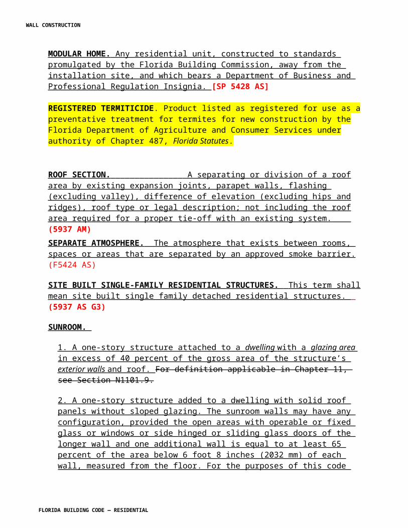
MODULAR HOME. Any residential unit, constructed to standards promulgated by the Florida Building Commission, away from the installation site, and which bears a Department of Business and Professional Regulation Insignia. [SP 5428 AS]
REGISTERED TERMITICIDE. Product listed as registered for use as a preventative treatment for termites for new construction by the Florida Department of Agriculture and Consumer Services under authority of Chapter 487, Florida Statutes.
ROOF SECTION. A separating or division of a roof area by existing expansion joints, parapet walls, flashing (excluding valley), difference of elevation (excluding hips and ridges), roof type or legal description; not including the roof area required for a proper tie-off with an existing system. (5937 AM)SEPARATE ATMOSPHERE. The atmosphere that exists between rooms, spaces or areas that are separated by an approved smoke barrier. (F5424 AS)
SITE BUILT SINGLE-FAMILY RESIDENTIAL STRUCTURES. This term shall mean site built single family detached residential structures. (5937 AS G3)
SUNROOM.
1. A one-story structure attached to a dwelling with a glazing area in excess of 40 percent of the gross area of the structure’s exterior walls and roof. For definition applicable in Chapter 11, see Section N1101.9.
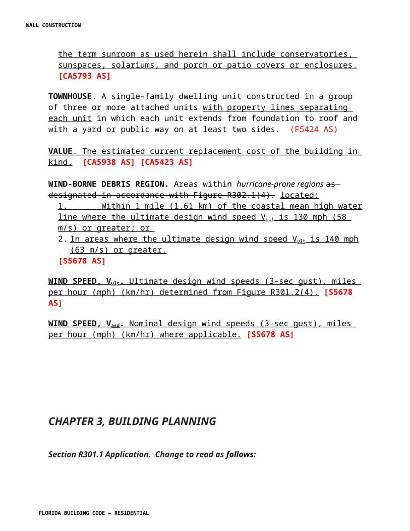
2. A one-story structure added to a dwelling with solid roof panels without sloped glazing. The sunroom walls may have any configuration, provided the open areas with operable or fixed glass or windows or side hinged or sliding glass doors of the longer wall and one additional wall is equal to at least 65 percent of the area below 6 foot 8 inches (2032 mm) of each wall, measured from the floor. For the purposes of this code the term sunroom as used herein shall include conservatories, sunspaces, solariums, and porch or patio covers or enclosures. [CA5793 AS]
WALL CONSTRUCTION
FLORIDA BUILDING CODE — RESIDENTIAL 7.21
TOWNHOUSE. A single-family dwelling unit constructed in a group of three or more attached units with property lines separating each unit in which each unit extends from foundation to roof and with a yard or public way on at least two sides. (F5424 AS)
VALUE . The estimated current replacement cost of the building in kind. [CA5938 AS] [CA5423 AS]
WIND-BORNE DEBRIS REGION. Areas within hurricane-prone regions as designated in accordance with Figure R302.1(4). located:
1. Within 1 mile (1.61 km) of the coastal mean high water line where the ultimate design wind speed Vult is 130 mph (58 m/s) or greater; or 2. In areas where the ultimate design wind speed V ult is 140 mph (63 m/s) or greater. [S5678 AS]
WIND SPEED, Vult. Ultimate design wind speeds (3-sec gust), miles per hour (mph) (km/hr) determined from Figure R301.2(4). [S5678 AS]
WIND SPEED, Vasd. Nominal design wind speeds (3-sec gust), miles per hour (mph) (km/hr) where applicable. [S5678 AS]
CHAPTER 3, BUILDING PLANNING
Section R301.1 Application. Change to read as follows:
R301.1 Application. Buildings and structures, and all parts thereof, shall be constructed to safely support all loads, including dead loads, live loads, roof loads, flood loads, and wind loads as prescribed by this code. The construction of buildings and structures in accordance with the provisions of this code shall result in a system that provides a complete load path that meets all requirements for the transfer of all loads from their point of origin through the load-resisting elements to the foundation. Buildings and structures constructed as prescribed by this code are deemed to comply with the requirements of this section.
Exception : Buildings and structures located within the High Velocity Hurricane Zone shall comply with Sections R302 to R324, inclusive and the provisions of Chapter R44 and section R406. In addition, buildings and structures located in flood hazard areas established in Table R301.2(1) shall comply with Sections R301.2.4 and R322. [SP 5290 AS]
WALL CONSTRUCTION
FLORIDA BUILDING CODE — RESIDENTIAL 7.22
Table R301.2(1). Change to read as shown:
TABLE R301.2(1) CLIMATIC AND GEOGRAPHIC DESIGN CRITERIA
[No change to table]
{Footnotes:]a.. – f. [No change]g. The applicable governing body shall, by local floodplain management ordinance, specify jurisdiction shall fill in this part of the table with (a) the date of the jurisdiction’s entry into the National Flood Insurance Program (date of adoption of the first code or ordinance for management of flood hazard areas), (b) the date(s) of the Flood Insurance Study and (c) the panel numbers and dates of all currently effective FIRM and FBFM, or other flood hazard map adopted by the authority having jurisdiction, as amended. [SP5290 AS]h. – j. [No change]
Table R301.2(2). Delete and replace with the following:
TABLE R301.2(2)COMPONENT AND CLADDING LOADS FOR A BUILDING WITH A MEAN ROOF
HEIGHT OF 30 FEET LOCATED IN EXPOSURE B (psf) a,b,c,d,e,f
ZONE
EFFECTIVE
WINDAREA(feet2)
Ultimate Design Wind Speed Vult (mph)
110 115 120 130 140 150 160 180 200Roof > 0 to
7 degre
es
1 10 8.9 -21.8 9.7 -23.8 10.5-
25.9 12.4 -30.4 14.3 -35.3 16.5 -40.5 18.7 -46.1 23.7 -58.3 29.3 -72.0
1 20 8.3 -21.2 9.1 -23.2 9.9-
25.2 11.6 -29.6 13.4 -34.4 15.4 -39.4 17.6 -44.9 22.2 -56.8 27.4 -70.1
1 50 7.6 -20.5 8.3 -22.4 9.0-
24.4 10.6 -28.6 12.3 -33.2 14.1 -38.1 16.0 -43.3 20.3 -54.8 25.0 -67.7
1 100 7.0 -19.9 7.7 -21.8 8.3-
23.7 9.8 -27.8 11.4 -32.3 13.0 -37.0 14.8 -42.1 18.8 -53.3 23.2 -65.9
2 10 8.9 -36.5 9.7 -39.9 10.5-
43.5 12.4 -51.0 14.3 -59.2 16.5 -67.9 18.7 -77.3 23.7 -97.8 29.3-
120.7
2 20 8.3 -32.6 9.1 -35.7 9.9-
38.8 11.6 -45.6 13.4 -52.9 15.4 -60.7 17.6 -69.0 22.2 -87.4 27.4-
107.9
2 50 7.6 -27.5 8.3 -30.1 9.0-
32.7 10.6 -38.4 12.3 -44.5 14.1 -51.1 16.0 -58.2 20.3 -73.6 25.0 -90.9
2 100 7.0 -23.6 7.7 -25.8 8.3-
28.1 9.8 -33.0 11.4 -38.2 13.0 -43.9 14.8 -50.0 18.8 -63.2 23.2 -78.1
3 10 8.9 -55.0 9.7 -21.8 10.5-
65.4 12.4 -76.8 14.3 -89.0 16.5-
102.2 18.7-
116.3 23.7-
147.2 29.3-
181.73 20 8.3 -45.5 9.1 -21.2 9.9 - 11.6 -63.6 13.4 -73.8 15.4 -84.7 17.6 -96.3 222 - 27.4 -
WALL CONSTRUCTION
FLORIDA BUILDING CODE — RESIDENTIAL 7.23
54.2 121.9 150.5
3 50 7.6 -33.1 8.3 -20.4 9.0-
39.3 10.6 -46.2 12.3 -53.5 14.1 -61.5 16.0 -69.9 20.3 -88.5 25.0-
109.3
3 100 7.0 -23.6 7.7 -19.8 8.3-
28.1 9.8 -33.0 11.4 -38.2 13.0 -43.9 14.8 -50.0 18.8 -63.2 23.2 -78.1
Roof > 7 to
27 degre
es
1 10 12.5 -19.9 13.7 -37.9 14.9-
23.7 17.5 -27.8 20.3 -32.3 23.3 -37.0 28.5 -42.1 33.6 -53.3 41.5 -65.9
1 20 11.4 -19.4 12.5 -34.9 13.6-
23.0 16.0 -27.0 18.5 -31.4 21.3 -36.0 24.2 -41.0 30.6 -51.9 37.8 -64.0
1 50 10.0 -18.6 10.9 -30.9 11.9-
22.2 13.9 -26.0 16.1 -30.2 18.5 -34.6 21.1 -39.4 26.7 -49.9 32.9 -61.6
1 100 8.9 -18.1 9.7 -27.8 10.5-
21.5 12.4 -25.2 14.3 -29.3 16.5 -33.6 18.7 -38.2 23.7 -48.4 29.3 -59.8
2 10 12.5 -34.7 13.7 -56.0 14.9-
41.3 17.5 -48.4 20.3 -56.2 23.3 -64.5 26.5 -73.4 33.6 -92.9 41.5-
114.6
2 20 11.4 -31.9 12.5 -52.4 13.6-
38.0 16.0 -44.6 18.5 -51.7 21.3 -59.3 24.2 -67.5 30.6 -85.4 37.8-
105.5
2 50 10.0 -28.2 10.9 -47.6 11.9-
33.6 13.9 -39.4 16.1 -45.7 18.5 -52.5 21.1 -59.7 26.7 -75.6 32.9 -93.3
2 100 8.9 -25.5 9.7 -44.0 10.5-
30.3 12.4 -35.6 14.3 -41.2 16.5 -47.3 18.7 -53.9 23.7 -68.2 29.3 -84.2
3 10 12.5 -51.3 13.7 -23.8 14.9-
61.0 17.5 -71.6 20.3 -83.1 23.3 -95.4 26.5-
108.5 33.6-
137.3 41.5-
169.5
3 20 11.4 -47.9 12.5 -22.6 13.6-
57.1 16.0 -67.0 18.5 -77.7 21.3 -89.2 24.2-
101.4 30.6-
128.4 37.8-
158.5
3 50 10.0 -43.5 10.9 -21.0 11.9-
51.8 13.9 -60.8 16.1 -70.5 18.5 -81.0 21.1 -92.1 26.7-
116.6 32.9-
143.9
3 100 8.9 -40.2 9.7 -19.8 10.5-
47.9 12.4 -56.2 14.3 -65.1 16.5 -74.8 18.7 -85.1 23.7-
107.7 29.3-
132.9Roof > 27 to 45 degre
es
1 10 19.9 -21.8 21.8 -27.6 23.7-
25.9 27.8 -30.4 32.3 -35.3 37.0 -40.5 42.1 -46.1 53.3 -58.3 65.9 -72.0
1 20 19.4 -20.7 21.2 -26.6 23.0-
24.6 27.0 -28.9 31.4 -33.5 36.0 -38.4 41.0 -43.7 51.9 -55.3 64.0 -68.3
1 50 18.6 -19.2 20.4 -25.0 22.2-
22.8 26.0 -26.8 30.2 -31.1 34.6 -35.7 39.4 -40.6 49.9 -51.4 61.6 -63.4
1 100 18.1 -18.1 19.8 -23.8 21.5-
21.5 25.2 -25.2 29.3 -29.3 33.6 -33.6 38.2 -38.2 48.4 -48.4 59.8 -59.8
2 10 19.9 -25.5 21.8 -27.8 23.7-
30.3 27.8 -35.6 32.3 -41.2 37.0 -47.3 42.1 -53.9 53.3 -68.2 65.9 -84.2
2 20 19.4 -24.3 21.2 -26.6 23.0-
29.0 27.0 -34.0 31.4 -39.4 36.0 -45.3 41.0 -51.5 51.9 -65.2 64.0 -80.5
2 50 18.6 -22.9 20.4 -25.0 22.2-
27.2 26.0 -32.0 30.2 -37.1 34.6 -42.5 39.4 -48.4 49.9 -61.3 61.6 -75.6
2 100 18.1 -21.8 19.8 -23.8 21.5-
25.9 25.2 -30.4 29.3 -35.3 33.6 -40.5 38.2 -46.1 48.4 -58.3 59.8 -72.03 10 19.9 -25.5 21.8 -27.8 23.7 -
30.327.8 -35.6 32.3 -41.2 37.0 -47.3 42.1 -53.9 53.3 -68.2 65.9 -84.2
WALL CONSTRUCTION
FLORIDA BUILDING CODE — RESIDENTIAL 7.24
3 20 19.4 -24.3 21.2 -26.6 23.0-
29.0 27.0 -34.0 31.4 -39.4 36.0 -45.3 41.0 -51.5 51.9 -65.2 64.0 -80.5
3 50 18.6 -22.9 20.4 -25.0 22.2-
27.2 26.0 -32.0 30.2 -37.1 34.6 -42.5 39.4 -48.4 49.9 -61.3 61.6 -75.6
3 100 18.1 -21.8 19.8 -23.6 21.5-
25.9 25.2 -30.4 29.3 -35.3 33.6 -40.5 38.2 -46.1 48.4 -58.3 59.8 -72.0
Wall
4 10 21.8 -23.6 23.8 -25.8 25.9-
28.1 30.4 -33.0 35.3 -38.2 40.5 -43.9 46.1 -50.0 58.3 -63.2 72.0 -78.1
4 20 20.8 -22.6 22.7 -24.7 24.7-
26.9 29.0 -31.6 33.7 -36.7 38.7 -42.1 44.0 -47.9 55.7 -60.6 68.7 -74.8
4 50 19.5 -21.3 21.3 -23.3 23.2-
25.4 27.2 -29.8 31.6 -34.6 36.2 -39.7 41.2 -45.1 52.2 -57.1 64.4 -70.6
4 100 18.5 -20.4 20.2 -22.2 22.0-
24.2 25.9 -28.4 30.0 -33.0 34.4 -37.8 39.2 -43.1 49.6 -54.5 61.2 -67.3
4 500 16.2 -18.1 17.7 -19.8 19.3-
21.5 22.7 -25.2 26.3 -29.3 30.2 -33.6 34.3 -38.2 43.5 -48.4 53.7 -59.8
5 10 21.8 -29.1 23.8 -31.9 25.9-
34.7 30.4 -40.7 35.3 -47.2 40.5 -54.2 46.1 -61.7 58.3 -78.0 72.0 -96.3
5 20 20.8 -27.2 22.7 -29.7 24.7-
32.4 29.0 -38.0 33.7 -44.0 38.7 -50.5 44.0 -57.5 55.7 -72.8 68.7 -89.9
5 50 19.5 -24.6 21.3 -26.9 23.2-
29.3 27.2 -34.3 31.6 -39.8 36.2 -45.7 41.2 -52.0 52.2 -65.8 64.4 -81.3
5 100 18.5 -22.6 20.2 -24.7 22.0-
26.9 25.9 -31.6 30.0 -36.7 34.4 -42.1 39.2 -47.9 49.6 -60.6 61.2 -74.8
5 500 16.2 -18.1 17.7 -19.8 19.3-
21.5 22.7 -25.2 26.3 -29.3 30.2 -33.6 34.3 -38.2 43.5 -48.4 53.7 -59.8 a. The effective wind area shall be equal to the span length multiplied by an effective width. This width shall be permitted to be not be less than one-third the span length. For cladding fasteners, the effective wind area shall not be greater than the area that is tributary to an individual fastener.b. For effective areas between those given above, the load may be interpolated; otherwise, use the load associated with the lower effective area.c. Table values shall be adjusted for height and exposure by multiplying by the adjustment coefficient in Table R301.2(3).d. See Figure R301.2(7) for location of zones.e. Plus and minus signs signify pressures acting toward and away from the building surfaces.f. Positive design wind pressures shall not be less than +16 psf and negative design wind pressures shall not be less than -16 psf. [S5702 AS]
Section R301.2.1 Wind design criteria. Change to read as shown:
R301.2.1 Wind design criteria. Buildings and portions thereof shall be constructed in accordance with the wind provisions of this code using the basic wind speed in Table R301.2(1) as determined from Figure R301.2(4)A. The structural provisions of this code for wind loads are not permitted where wind design is required as specified in Section R301.2.1.1. Where different construction methods and structural materials are used for various portions of a building, the applicable requirements of this section for each portion shall apply. Where not otherwise specified, the wind loads listed in Table R301.2(2) adjusted for height and exposure using Table R301.2(3) shall be used to determine design load
WALL CONSTRUCTION
FLORIDA BUILDING CODE — RESIDENTIAL 7.25
performance requirements for wall coverings, curtain walls, roof coverings, exterior windows, skylights, garage doors and exterior doors (other than garage doors). Where loads for garage doors are not otherwise specified, the loads listed in Table R301.2(4) adjusted for height and exposure using Table R301.2(3) shall be used to determine design load performance requirements. Asphalt shingles shall be designed for wind speeds in accordance with Section R905.2.4. A continuous load path shall be provided to transmit the applicable uplift forces in Section R802.11.1 from the roof assembly to the foundation.
(S5328AM) (S5681 AS)
Add the following table:
TABLE R301.2(4)NOMINAL (ASD) GARAGE DOOR LOADS FOR A BUILDING WITH A
MEAN ROOF HEIGHT OF 30 FEET LOCATED IN EXPOSURE B (PSF) 1,2,3,4,5
ULTIMATE DESIGN WIND SPEED Vult as Determined in Accordance with Section R301.2.1.3 (mph – 3 second gust)Roof Angle>10 degrees
100 mph 110 mph 120 mph 130 mph 140 mph 150 mph 160 mph 170 mph 180 mph 190 mph 200 mph
Width (ft) Height (ft)9 7 9.6 -10.9 11.4 -12.9 13.7 -15.5 16.1 -18.2 18.5 -20.9 21.3 -24.1 24.3 -27.5 27.6 -31.2 30.6 -34.6 34.2 -38.6 38.0 -43.016 7 9.2 -10.3 10.9 -12.2 13.1 -14.6 15.5 -17.2 17.7 -19.7 20.4 -22.7 23.3 -26.0 26.4 -29.4 29.3 -32.6 32.7 -36.5 36.4 -40.6
78 mph 85 mph 93 mph 101 mph 108 mph 116 mph 124 mph 132 mph 139 mph 147 mph 155 mphNominal Design Wind Speed Vasd Converted from Vult per Table R301.2.1.3
For SI: 1 foot = 304.8 mm, 1 mile per hour = 1.609 km/h, 1 psf = 47.88 N/m 2 1. For effective areas or wind speeds between those given above the load may be interpolated, otherwise use the load associated with the lower effective area.2. Table values shall be adjusted for height and exposure by multiplying by the adjustment coefficient in Table R301.2(3)3. Plus and minus signs signify pressures acting toward and away from the building surfaces.4. Negative pressures assume door has 2 feet of width in building's end zone.5.Table values include the 0.6 load reduction factor.
(S5328 AM R1)
Section R301.2.1.1 Wind limitations and wind design required. Change to read as shown:
R301.2.1.1 Wind limitations and wind design required. The wind provisions of this code shall not apply to the design of buildings where wind design is required in accordance with Figure R301.2(4)B or where the basic ultimate design wind speed, V ult , from Figure R301.2(4)A equals or exceeds 115 110 miles per hour (51 49 m/s).Exceptions:
1. For concrete construction, the wind provisions of this code shall apply in accordance with the limitations of Sections R404 and R611.2. For structural insulated panels, the wind provisions of this code shall apply in accordance with the limitations of Section R613.
In regions where wind design is required in accordance with Figure R301.2(4)B or where the basic ultimate design wind speed, V ult , shown on Figure R301.2(4)A equals or exceeds
WALL CONSTRUCTION
FLORIDA BUILDING CODE — RESIDENTIAL 7.26
115 110 miles per hour (51 49 m/s), the design of buildings for wind loads shall be in accordance with one or more of the following methods:
1. AF&PA Wood Frame Construction Manual (WFCM); or 2. ICC Standard for Residential Construction in High-Wind Regions (ICC 600); or3. ASCE Minimum Design Loads for Buildings and Other Structures (ASCE 7); or4. AISI Standard for Cold-Formed Steel Framing—Prescriptive Method For One- and Two-Family Dwellings (AISI S230); or5. International Florida Building Code.6. Concrete masonry construction shall be designed in accordance with the provisions of this code or in accordance with TMS 402/ACI 530/ASCE 5 and TMS 602/ACI 530.1/ASCE 6; or7. The MAF Guide to Concrete Masonry Residential Construction in High Wind Areas shall be permitted for applicable concrete masonry buildings for a basic wind speed of 130 mph (58 m/s) or less in Exposure B and 110 mph (49 m/s) or less in Exposure C in accordance with Figure R301.2(4) as converted in accordance with R301.2.1.3.
The wind speeds in Figure R301.2(4) shall be converted to nominal wind speeds, Vasd, in accordance with Section R301.2.1.3 when the provisions of the standards referenced in 2 through 4 are used unless the wind provisions in the standards are based on Ultimate Wind Speeds as specified in Figure R301.2(4) or Chapter 26 of ASCE 7.
The elements of design not addressed by the methods in Items 1 through 5 7 shall be in accordance with the provisions of this code. When ASCE 7 or the International Florida Building Code is used for the design of the building, the wind speed map and exposure category requirements as specified in ASCE 7 and the International Florida Building Code shall be used.
[S5681 AS] [S5998 AS]
Delete Figures R301.2(4)A, R301.2(4)B, and R301.2(4)C as shown:
FIGURE R301.2(4)ABASIC WIND SPEEDS
FIGURE R301.2(4)BREGIONS WHERE WIND DESIGN IS REQUIRED
FIGURE R301.2(4)CWIND-BORNE DEBRIS REGIONS
Insert Figure R301.2(4) as follows:
WALL CONSTRUCTION
FLORIDA BUILDING CODE — RESIDENTIAL 7.27
[S5681 AS]
Modify Figure R301.2(4)A - add footnote 5 as follows:
5. This map is accurate to the county. Local governments establish specific wind speed/wind-borne debris lines using physical landmarks such as major roads, canals, rivers, and shorelines.
(S5430AS)
Section R301.2.1.1.1 Add a new section as shown:
R301.2.1.1.1 Aluminum structure design. The AAF Guide to Aluminum Construction in High-Wind Areas shall be permitted for the construction of the aluminum structures therein addressed. Screen enclosures shall be permitted to be designed in accordance with the Florida Building Code Section 2002. Vinyl and acrylic panels shall be permitted and shall be removable. Removable panels shall be identified as removable by a decal. The identification decal shall essentially state: “Removable panel SHALL be removed when wind speeds exceed 75 mph (34 m/s).” Decals shall be placed such that the decal is visible
WALL CONSTRUCTION
FLORIDA BUILDING CODE — RESIDENTIAL 7.28
when the panel is installed. [S5790 AS]
R301.2.1.1.2 Add new section as shown:
R301.2.1.1.2 Sunroom design.
R301.2.1.1.2.1 Sunrooms shall comply with AAMA/NPEA/NSA 2100.
R301.2.1.1.2.2 For the purpose of applying the criteria of the AAMA/NPEA/NSA 2100, sunrooms shall be categorized in one of the following categories by the permit applicant, design professional or the property owner where the sunroom is being constructed.
Category I: A Thermally Isolated Sunroom with walls that are either open or enclosed with insect screening or 0.5 mm (20 mil) maximum thickness plastic film. The space is defined as a non-habitable, non-conditioned sunroom.
Category II: A Thermally Isolated Sunroom with enclosed walls. The openings are permitted to be enclosed with translucent or transparent plastic or glass. The space is defined as a non-habitable, non-conditioned sunroom.
Category III: A Thermally Isolated Sunroom with enclosed walls. The openings are permitted to be enclosed with translucent or transparent plastic or glass. The sunroom fenestration complies with additional requirements for air infiltration resistance and water penetration resistance. The space is defined as a non-habitable, non-conditioned sunroom.
Category IV: A Thermally Isolated Sunroom with enclosed walls. The sunroom is designed to be heated and or cooled by a separate temperature control or system and is thermally isolated from the primary structure. The sunroom fenestration complies with additional requirements for air infiltration resistance, water penetration resistance, and thermal performance. The space is defined as a non-habitable and conditioned sunroom.
Category V: A Sunroom with enclosed walls. The sunroom is designed to be heated and or cooled and is open to the main structure. The sunroom fenestration complies with additional requirements for air infiltration resistance, water penetration resistance, and thermal performance. The space is defined as a habitable and conditioned sunroom.
[S5791 AS]
WALL CONSTRUCTION
FLORIDA BUILDING CODE — RESIDENTIAL 7.29
Section R301.2.1.2 Protection of openings. Change to read as follows:
R301.2.1.2 Protection of openings. Exterior glazing Glazed openings in buildings located in windborne debris regions shall be protected from windborne debris. Glazed opening protection for windborne debris shall meet the requirements of the Large Missile Test of ASTM E 1996 and ASTM E 1886 referenced therein, SSTD 12, TAS 201,202, and 203 or AAMA 506, as applicable. The applicable wind zones for establishing missile types in ASTM E 1996 are shown in Section R301.2.1.2.1 on Figure R301.2 (4) . Garage door glazed opening protection for windborne debris shall meet the requirements of an approved impact-resisting standard or ANSI/DASMA 115
[S5663 AM R1] [S5718 AS] [S5681 AS]
1. Opening in sunrooms, balconies or enclosed porches constructed under existing roofs or decks are not required to be protected provided the spaces are separated from the building interior by a wall and all openings in the separating wall are protected in accordance with this section. Such space shall be permitted to be designed as either partially enclosed or enclosed structures. [S5432 AS]
2. Storage sheds that are not designed for human habitation and that have a floor area of 720 square feet (67 m2) or less are not required to comply with the mandatory wind-borne debris impact standard of this code. [S5432 AS]
Exception: Wood structural panels with a minimum thickness of 7/16 inch (11 mm) and a maximum span of 8 feet (2438 mm) shall be permitted for opening protection in one- and two-story buildings. Panels shall be precut and attached to the framing surrounding the opening containing the product with the glazed opening. Panels shall be predrilled as required for the anchorage method and shall be secured with the attachment hardware provided. Attachments shall be designed to resist the component and cladding loads determined in accordance with either Table R301.2(2) or ASCE 7, with the permanent corrosion-resistant attachment hardware provided and anchors permanently installed on the building. Attachment in accordance with Table R301.2.1.2 is permitted for buildings with a mean roof height of 33 feet (10 058 mm) or less where Vasd determined in accordance with Section R301.2.3, does not exceed 130 miles per hour (58 m/s) located in Wind Zones 1 and 2 in accordance with Figure R301.2(4)C.
R301.2.1.2.1 Modifications to ASTM E 1996. Section 6.2.2 of ASTM E 1996 shall be modified as follows:
6.2.2 Unless otherwise specified, select the wind zone based on the basic wind speed as follows:
6.2.2.1WindZone 1 - 130 mph < basic wind speed < 140 mph, and Hawaii.
WALL CONSTRUCTION
FLORIDA BUILDING CODE — RESIDENTIAL 7.30
6.2.2.2 Wind Zone 2 - 140 mph < basic wind speed < 150 mph at greater than 1.6 km (one mile) from the coastline. The coastline shall be measured from the mean high water mark.
6.2.2.3 Wind Zone 3 - 150 mph (58 m/s) < basic wind speed < 170 mph (63 m/s), or 140 mph (54 m/s) < basic wind speed < 170 mph (63 m/s) and within 1.6 km (one mile) of the coastline. The coastline shall be measured from the mean high water mark.
6.2.2.4 Wind Zone 4- basic wind speed > 170 mph (63 m/s).
(S5721 AS) (S5681 AS)
R301.2.1.2.1.1 Modifications to ASTM E 1886 and ASTM E 1996.
Table 1 of ASTM E 1886 and ASTM E 1996 – add column and notes to read as follows:
Air Pressure Cycles0.2 to 0.5 Ppos
1
0.0 to 0.6 Ppos
0.5 to 0.8 Ppos
0.3 to 1.0 Ppos
0.3 to 1.0 Pneg2
0.5 to 0.8 Pneg
0.0 to 0.6 Pneg
0.2 to 0.5 Pneg Notes:1. Ppos = 0.6 x positive ultimate design load in accordance with ASCE 7. 2. P neg = 0.6 x negative ultimate design load in accordance with ASCE 7.
[S5681 AS]
Section R301.2.1.3 Wind speed conversion. Change to read as follows:
R301.2.1.3 Wind speed conversion. When required referenced documents are based on fastest mile wind speeds, the three-second gust basic ultimate design wind speeds, Vult, wind speeds, V3s, of Figure R301.2(4) shall be converted to fastest mile nominal design wind speeds, Vasd Vfm, using Table R301.2.1.3.
Delete existing Table R301.2.1.3 and replace with the following:
WALL CONSTRUCTION
FLORIDA BUILDING CODE — RESIDENTIAL 7.31
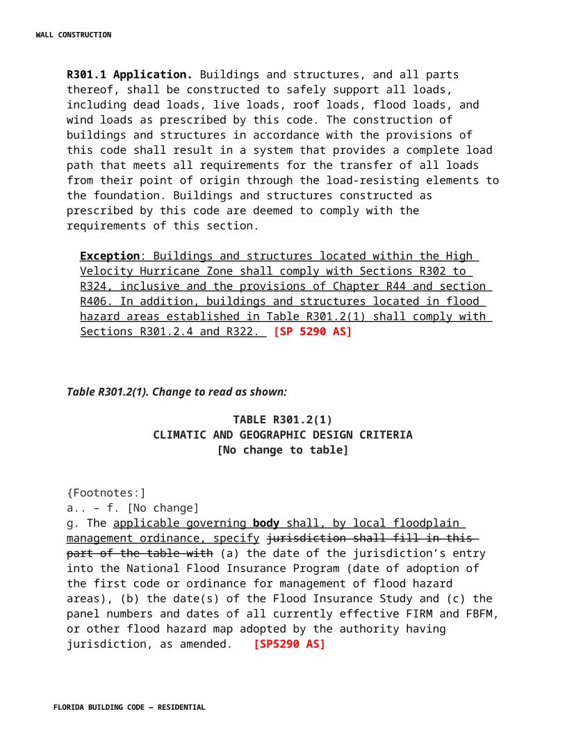
TABLE R301.2.1.3WIND SPEED CONVERSIONS abc
Vult 100 110 120 130 140 150 160 170 180 190 200Vasd 78 85 93 101 108 116 124 132 139 147 155a. Linear interpolation is permitted b. V asd = nominal design wind speed c. V ult = ultimate design wind speed determined from Figure R301.2(4).
[S5681 AS]
Section R301.2.1.4. Exposure category. Change to read as follows:
R301.2.1.4 Exposure category. For each wind direction considered, an exposure category that adequately reflects the characteristics of ground surface irregularities shall be determined for the site at which the building or structure is to be constructed. For a site located in the transition zone between categories, the category resulting in the largest wind forces shall apply. Account shall be taken of variations in ground surface roughness that arise from natural topography and vegetation as well as from constructed features. For any given wind direction, the exposure in which a specific building or other structure is sited shall be assessed as being one of the following categories. . For a site where multiple detached one- and two-family dwellings, townhouses or other structures are to be constructed as part of a subdivision, master-planned community, or otherwise designated as a developed area by the authority having jurisdiction, the exposure category for an individual structure shall be based upon the site conditions that will exist at the time when all adjacent structures on the site have been constructed, provided their construction is expected to begin within one year of the start of construction for the structure for which the exposure category is determined. For any given wind direction, the exposure in which a specific building or other structure is sited shall be assessed as being one of the following categories:
1. Exposure A. Large city centers with at least 50 percent of the buildings having a height in excess of 70 feet (21 336 mm). Use of this exposure category shall be limited to those areas for which terrain representative of Exposure A prevails in the upwind direction for a distance of at least 0.5 mile (0.8 km) or 10 times the height of the building or other structure, whichever is greater. Possible channeling effects or increased velocity pressures due to the building or structure being located in the wake of adjacent buildings shall be taken into account.2. Exposure B. Urban and suburban areas, wooded areas, or other terrain with numerous closely spaced obstructions having the size of single family dwellings or larger. Exposure B shall be assumed unless the site meets the definition of another type exposure.3. Exposure C. Open terrain with scattered obstructions, including surface undulations or other irregularities, having heights generally less than 30 feet (9144 mm) extending more than 1,500 feet (457 m) from the building site in any quadrant. This exposure shall
WALL CONSTRUCTION
FLORIDA BUILDING CODE — RESIDENTIAL 7.32
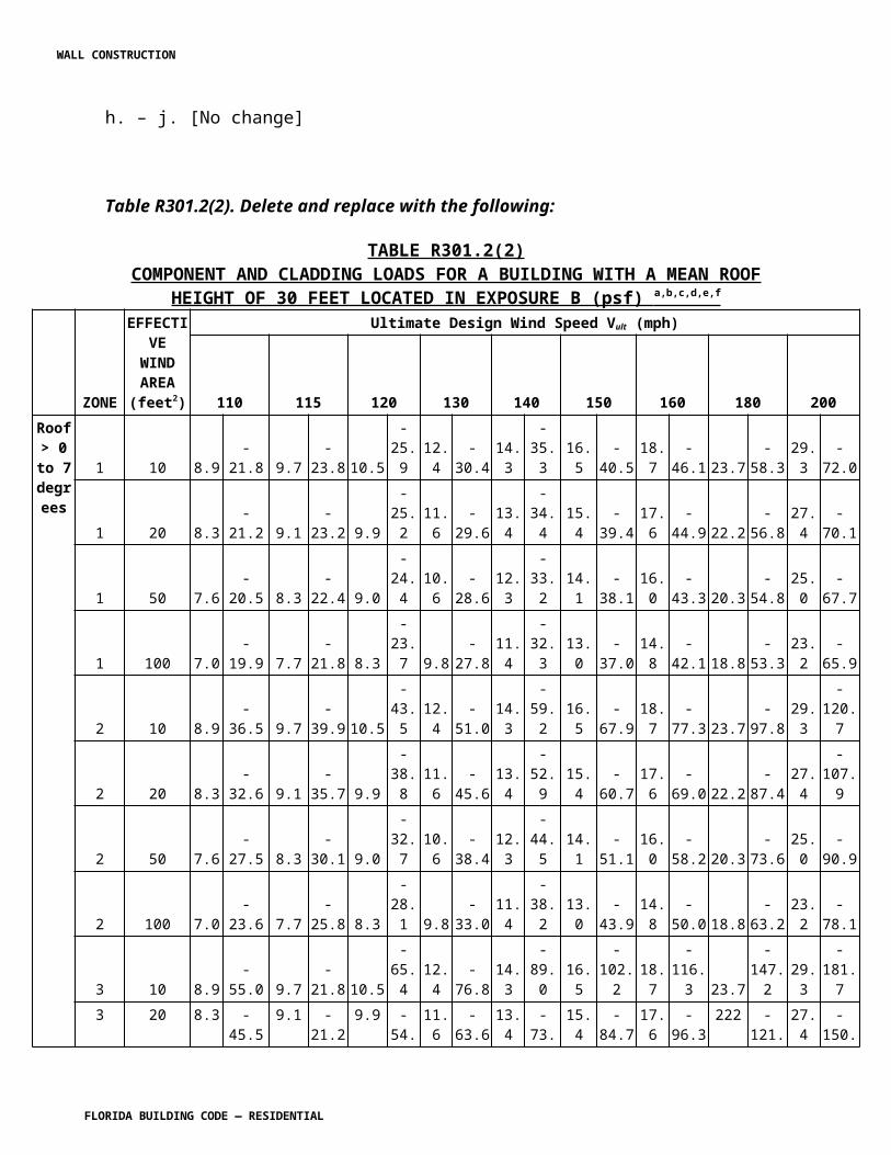
also apply to any building located within Exposure B type terrain where the building is directly adjacent to open areas of Exposure C type terrain in any quadrant for a distance of more than 600 feet (183 m). This category includes flat, open country and grasslands.4. Exposure D. Flat, unobstructed areas exposed to wind flowing over open water for a distance of at least 1 mile (1.61 km). Shorelines in Exposure D include inland waterways, the Great Lakes, and coastal areas of California, Oregon, Washington and Alaska. This exposure shall apply only to those buildings and other structures exposed to the wind coming from over the water. Exposure D extends inland from the shoreline a distance of 1500 feet (457 m) or 10 times the height of the building or structure, whichever is greater.
Exception : An intermediate exposure between the exposure categories defined is permitted in a transition zone provided that it is determined by a rational analysis method.
R301.2.1.4.1 Wind directions and sectors. For each selected wind direction at which the wind loads are to be evaluated, the exposure of the building or structure shall be determined for the two upwind sectors extending 45 degrees (0.79 rad) either side of the selected wind direction. The exposures in these two sectors shall be determined in accordance with Sections R301.2.4.2 and R301.2.1.4.3 and the exposure resulting in the highest wind loads shall be used to represent winds from that direction.
R301.2.1.4.2 Surface roughness categories. A ground surface roughness within each 45-degree 4(0.79 rad) sector shall be determined for a distance upwind of the site as defined in Section R301.2.1.4.3 from the categories defined below, for the purpose of assigning an exposure category as defined in Section R301.2.1.4.3.
Surface Roughness B. Urban and suburban areas, wooded areas or other terrain with numerous closely spaced obstructions having the size of single-family dwellings or larger.
Surface Roughness C. Open terrain with scattered obstructions having heights generally less than 30 feet (9144 mm). This category includes flat open country and grasslands. This surface roughness shall also apply to any building located within surface roughness B-type terrain where the building is within 100 feet horizontally in any direction of open areas of surface roughness C or D-type terrain that extends more than 600 feet (182.9 m) and width greater than 150 ft. in the upwind direction. Short-term (less than two year) changes in the pre-existing terrain exposure, for the purposes of development, shall not be considered surface roughness C. Where development buildout will occur within three years and the resultant condition will meet the definition of surface roughness B, surface roughness B shall be regulating for the purpose of permitting. This category includes flat open country and grasslands and shall extend downwind for a distance of 1500 feet.
Surface Roughness D. Flat, unobstructed areas and water surfaces. This category includes smooth mud flats, salt flats and unbroken ice.
WALL CONSTRUCTION
FLORIDA BUILDING CODE — RESIDENTIAL 7.33
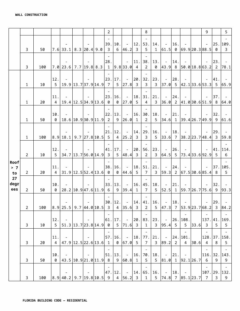
R301.2.1.4.3 Exposure categories. An exposure category shall be determined in accordance with the following:
Exposure B. For buildings with a mean roof height of less than or equal to 30 feet, Exposure B shall apply where the ground surface roughness, as defined by Surface Roughness B, prevails in the upwind direction for a distance of at least 1,500 ft (457 m). For buildings with a mean roof height greater than 30 ft, Exposure B shall apply where Surface Roughness B prevails in the upwind direction for a distance of at least 2,600 feet (792 m) or 20 times the height of the building, whichever is greater.
Exposure C. Exposure C shall apply for all cases where Exposures B or D do not apply.
Exposure D. Exposure D shall apply where the ground surface roughness, as defined by Surface Roughness D, prevails in the upwind direction for a distance of at least 5,000 feet (1524 m) or 20 times the height of the building, whichever is greater. Exposure D shall also apply where the ground surface roughness immediately upwind of the site is B or C, and the site is within a distance of 600ft (183 m) or 20 times the building height, whichever is greater, from an exposure D condition as defined in the previous sentence.
[S5694 AS]
Section R301.2.1.6. Add the following section to read as follows:
R301.2.1.6 Testing to allowable or nominal loads. Where testing for wind load resistance is based on allowable or nominal wind loads, the design wind loads determined in accordance with ASCE 7 or Section 1609 of the Florida Building Code, Building are permitted to be multiplied by 0.6 for the purposes of the wind load resistance testing. [S5700 AS]
Section R301.2.4.1. Change to read as follows:
R301.2.4.1 Alternative provisions. As an alternative to the requirements in Section R322, R322.3 for buildings and structures located in whole or in part in coastal high-hazard areas (V Zones) and Coastal A Zones, if delineated, ASCE 24 is permitted subject to the limitations of this code and the limitations therein.
[SP 5292 AS][F5902 AS]
R301.2.5 Add to read as follows:
WALL CONSTRUCTION
FLORIDA BUILDING CODE — RESIDENTIAL 7.34
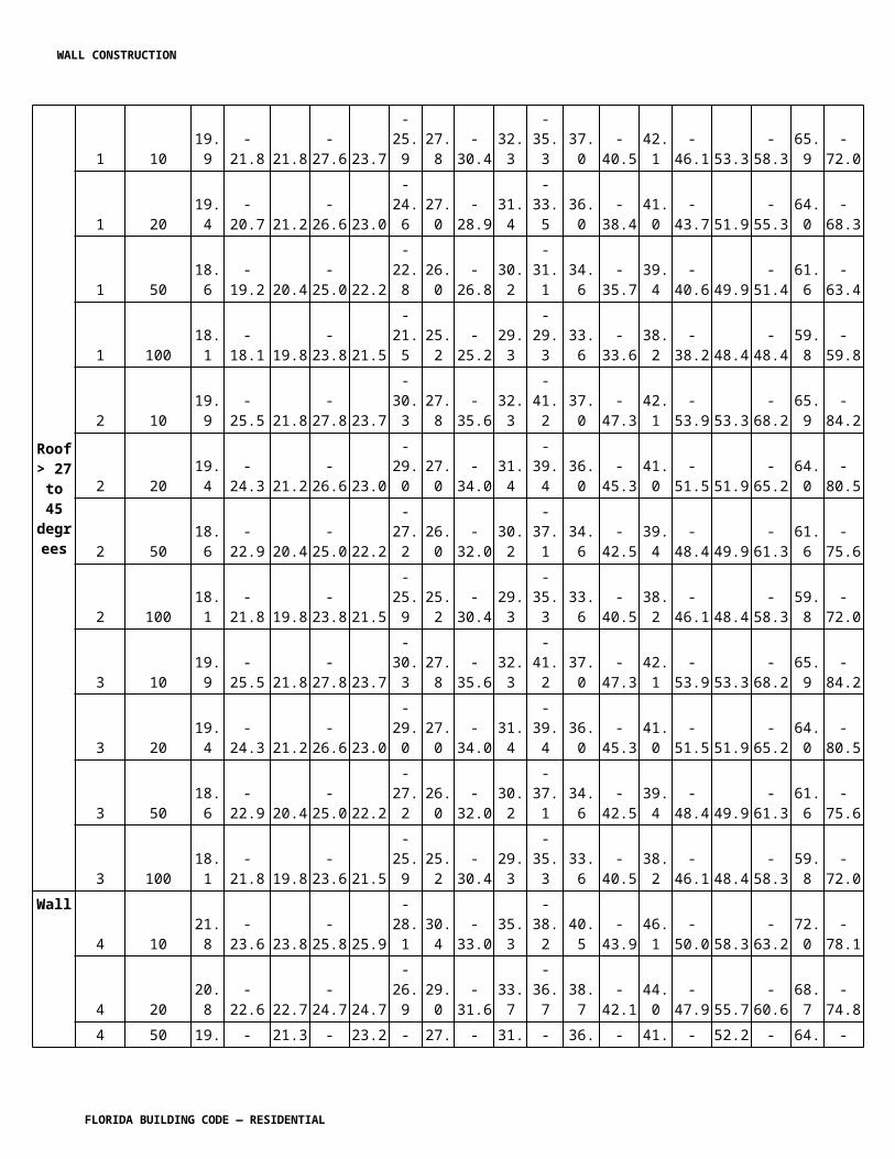
R301.2.5 Structures seaward of a coastal control construction line. Structures located seaward of the coastal construction control line shall be designed to resist the predicted forces of a 100-year storm event in accordance with Section 3109 of the Florida Building Code, Building.
Section R301.9. Add to read as follows:
R301.9 All exterior wall coverings and soffits shall be capable of resisting the design pressures specified for walls for components and cladding loads in accordance with Table R301.2(2) as modified by Table R301.2(3), Manufactured soffits shall be tested at 1.5 times the design pressure.
[S5743 AS]
Section R302.1 Exterior walls. Change to read as follows:
R302.1 Exterior walls. Construction, projections, openings and penetrations of exterior walls of dwellings and accessory buildings shall comply with Table R302.1(1); or dwellings equipped throughout with an automatic sprinkler system installed in accordance with Section P2904 shall comply with Table R302.1(2).
Exceptions:1.-5. [No change]6. Screen enclosure walls of insect screening with a maximum of 25% solid flexible finishes.
[F5902 AS]
Section R302.2. Townhouses. Change to read as shown:
R302.2 Townhouses. Each townhouse shall be considered a separate building and shall be separated by fire-resistance- rated wall assemblies meeting the requirements of Section R302.1 for exterior walls.
Exception: A common 1-hour 2-hour fire-resistance-rated wall assembly tested in accordance with ASTME 119 or UL 263 is permitted for townhouses if such walls do not contain plumbing or mechanical equipment, ducts or vents in the cavity of the common wall, unless such materials and methods of penetration comply with Section R302.4. The wall shall be rated for fire exposure from both sides and shall extend to and be tight against exterior walls and the underside of the roof sheathing. Electrical installations shall be installed in accordance with Chapters 34 through 43. Penetrations of electrical outlet boxes shall be in accordance with Section R302.4.
[F6011 AS]
WALL CONSTRUCTION
FLORIDA BUILDING CODE — RESIDENTIAL 7.35
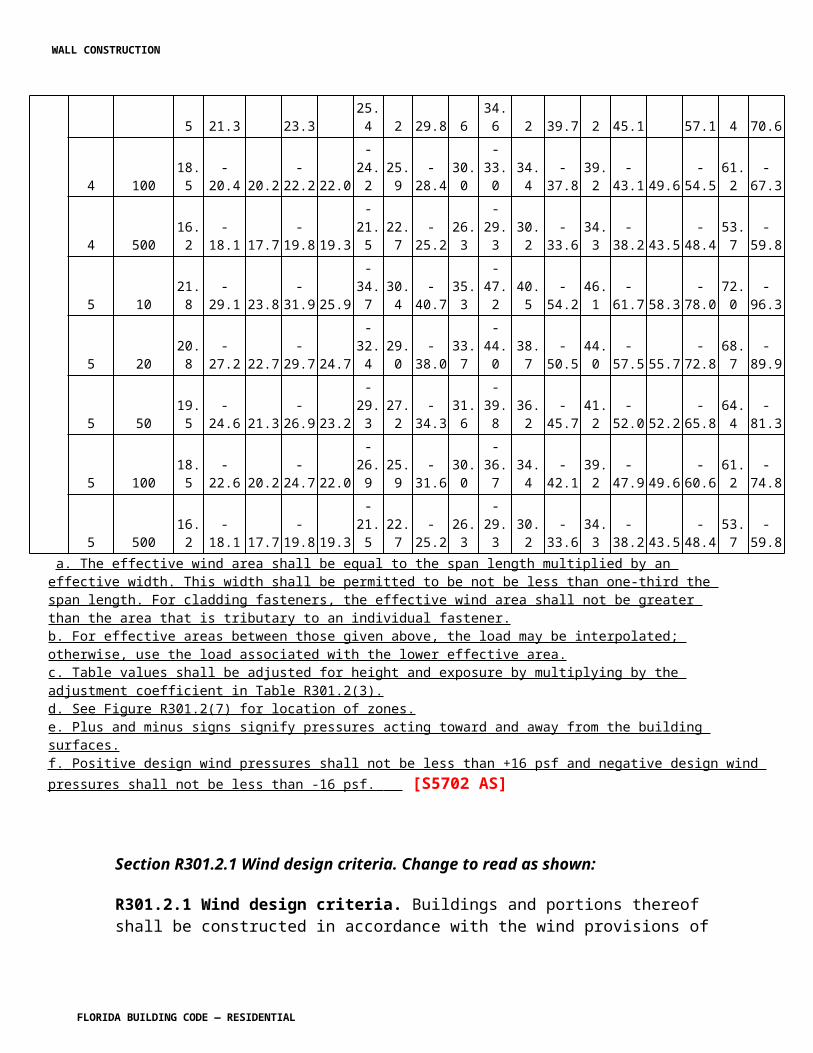
Section R302.3. Revise to read as shown:
R302.3 Two-family dwellings. Dwelling units in two-family dwellings shall be separated from each other by wall and/or floor assemblies having not less than a 1-hour fire-resistance rating when tested in accordance with ASTM E 119 or UL 263. Fire-resistance-rated floor/ceiling and wall assemblies shall extend to and be tight against the exterior wall, and wall assemblies shall extend from the foundation to the underside of the roof sheathing.
Exceptions:1. – 2. [No change] 3. Screen enclosure walls of insect screening with a maximum of 25 percent solid flexible finishes.
[F5904 AS]
R302.5.2 Duct penetration. Change to read as shown:
R302.5.2 Duct penetration. Ducts in the garage and ducts penetrating the walls or ceilings separating the dwelling from the garage shall be constructed of a minimum No. 26 gage (0.48 mm) sheet steel, 1 inch minimum rigid nonmetallic Class 0 or Class 1 duct board, or other approved material and shall have no openings into the garage,
[F5417 AS] [M5868 AS ]
Section R306.3 Sewage disposal. Change to read as shown:
R306.3 Sewage disposal. All plumbing fixtures shall be connected to a sanitary sewer or to an approved private sewage disposal system in accordance with Chapter 64E-6, Florida Administrative Code, Standards for Onsite Sewage Treatment and Disposal Systems.
[SP5434 AS]
Section R308.1 Identification. Change to read as shown:
R308.1 Identification. Each pane shall bear the manufacturer's label designating the type and thickness of glass or glazing material. Except as indicated in Section R308.1.1 each pane of glazing installed in hazardous locations as defined in Section R308.4 shall be provided with a manufacturer’s or installer's label, designation specifying who applied the designation, designating the type of glass and the safety glazing standard with which it complies, which is visible in the final installation. The designation safety glazing label shall be acid etched, sandblasted, ceramic-fired, laser etched, embossed, or be of a type which once applied cannot be removed without being destroyed. A label shall be permitted in lieu of the manufacturer’s designation. Laminated glass, other than used for safety glazing, shall be permanently identified as per this section, designating laminator, overall glass thickness and trade name of interlayer.
WALL CONSTRUCTION
FLORIDA BUILDING CODE — RESIDENTIAL 7.36
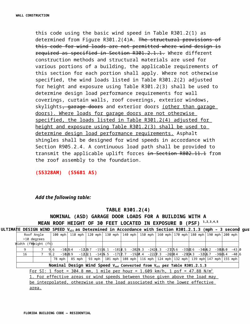
Exceptions:
1. For other than tempered glass, manufacturer’s designations are not required provided the building official approves the use of a certificate, affidavit or other evidence furnished by the gazing contractor certifying that each light id glazed in accordance with approved construction documents that comply with the provisions of this chapter confirming compliance with this code.2. Tempered spandrel glass is permitted to be identified by the manufacturer with a removable paper designation label
[S5822 AS]
R310.1 Emergency escape and rescue required. Change to read as follows:
R310.1 Emergency escape and rescue required. [No change to text; exceptions only]Exceptions: 71. Basements used only to house mechanical equipment and not exceeding total floor area of 200 square feet (18.58 m2).2. The emergency escape and rescue opening shall be permitted to open into a screen enclosure, open to the atmosphere, where a screen door is provided leading away from the residence.
[F5419 AS]
R310.4 Bars, grills, covers and screens. Change to read as shown:
R310.4 Bars, grills, covers and screens. Bars, grills, covers, screens or similar devices are permitted to be placed over emergency escape and rescue openings, bulkhead enclosures, or window wells that serve such openings, provided the minimum net clear opening size complies with Sections R310.1.1 to R310.1.3, and such devices shall be releasable or removable from the inside without the use of a key, tool, special knowledge or force greater than that which is required for normal operation of the escape and rescue opening. The temporary installation or closure of storm shutters, panels, and other approved hurricane protection devices shall be permitted on emergency escape and rescue openings during the threat of a storm. Such devices shall not be required to comply with the operational constraints of Section R310.1.4. While such protection is provided, at least one means of escape from the dwelling or dwelling unit shall be provided. The means of escape shall be within the first floor of the dwelling or dwelling unit and shall not be located within a garage without a side-hinged door leading directly to the exterior.
Occupants in any part of the dwelling or dwelling unit shall be able to access the means of escape without passing through a lockable door not under their control .
[F5717 AS]
WALL CONSTRUCTION
FLORIDA BUILDING CODE — RESIDENTIAL 7.37
Section R311.2 Egress door. Add exception to read as follows:
R311.2 Egress door. At least one egress door shall be provided for each dwelling unit. The egress door shall be side-hinged, and shall provide a minimum clear width of 32 inches (813 mm) when measured between the face of the door and the stop, with the door open 90 degrees (1.57 rad). The minimum clear height of the door opening shall not be less than 78 inches (1981 mm) in height measured from the top of the threshold to the bottom of the stop. Other doors shall not be required to comply with these minimum dimensions. Egress doors shall be readily openable from inside the dwelling without the use of a key or special knowledge or effort.
Exception: Buildings that are 400 square feet or less and that are intended for use in conjunction with one- and two-family residences are not subject to the door height and width requirements of this code.
[SP5436 AS]
Section R311.3 Floors and landings at exterior doors. Change to read as shown:
R311.3 Floors and landings at exterior doors. There shall be a landing or floor on each side of each exterior door. The width of each landing shall not be less than the door served. Every landing shall have a minimum dimension of 36 inches (914 mm) measured in the direction of travel. Exterior landings shall be permitted to have a slope not to exceed 1/4 unit vertical in 12 units horizontal (2-percent).
Exception: Exterior balconies less than 60 square feet (5.6m2) and only accessible from a door are permitted to have a landing less than 36 inches (914 mm) measured in the direction of travel.
R311.3.1 Floor elevations at the required egress doors. Landings or finished floors at the required egress door shall not be more than l ½ inches (38 mm) lower than the top of the threshold.
Exception: The landing or floor on the exterior side shall not be more than 7-3/4 inches (196 mm) below the top of the threshold provided the door does not swing over the landing or floor.
Where exterior landings of floors serving the required egress door are not at grade, they shall be provided with access to grade by means of a ramp in accordance with Section R311.8 or a stairway in accordance with Section R311.7.
R311.3.2 Floor elevations for other exterior doors. Doors other than the required egress door shall be provided with landings or floors not more than 7-3/4, inches (196 mm) below the top of the threshold.
Exception: A landing is not required where a stairway of two or fewer risers is located on the exterior side of the door. , provided the door does not swing over the stairway.
[F5415 AS]
WALL CONSTRUCTION
FLORIDA BUILDING CODE — RESIDENTIAL 7.38
Section R311.7.6, Landings for stairways. Add exception 2 as shown:
R311.7.6 Landings for stairways. There shall be a floor or landing at the top and bottom of each stairway. The minimum width perpendicular to the direction of travel shall be no less than the width of the flight served. Landings of shapes other than square or rectangular shall be permitted provided the depth at the walk line and the total area is not less than that of a quarter circle with a radius equal to the required landing width. Where the stairway has a straight run, the minimum depth in the direction of travel shall be not less than 36 inches (914 mm).
Exceptions: 1. A floor or landing is not required at the top of an interior flight of stairs, including stairs in an enclosed garage, provided a door does not swing over the stairs.2. See Section R311.3 from exterior doors where a step down is provided.
[F5415 AS]
Section R313 Automatic Fire Sprinkler. Change to read as follows:
SECTION R313AUTOMATIC FIRE SPRINKLER
RESERVED
R313.1 Townhouse automatic fire sprinkler systems. An automatic residential fire sprinkler system shall be installed in townhouses.
Exception: An automatic residential fire sprinkler system shall not be required when additions or alterations are made to existing townhouses that do not have an automatic residential fire sprinkler system installed.
R313.1.1 Design and installation. Automatic residential fire sprinkler systems for townhouses shall be designed and installed in accordance with Section P2904.
R313.2 One- and two-family dwellings automatic fire systems. An automatic residential fire sprinkler system shall be installed in one- and two-family dwellings.
Exception: An automatic residential fire sprinkler system shall not be required for additions or alterations to existing buildings that are not already provided with an automatic residential sprinkler system.
R313.2.1 Design and installation. Automatic residential fire sprinkler systems shall be designed and installed in accordance with Section P2904 or NFPA 13D.
[F5437 AS]
WALL CONSTRUCTION
FLORIDA BUILDING CODE — RESIDENTIAL 7.39
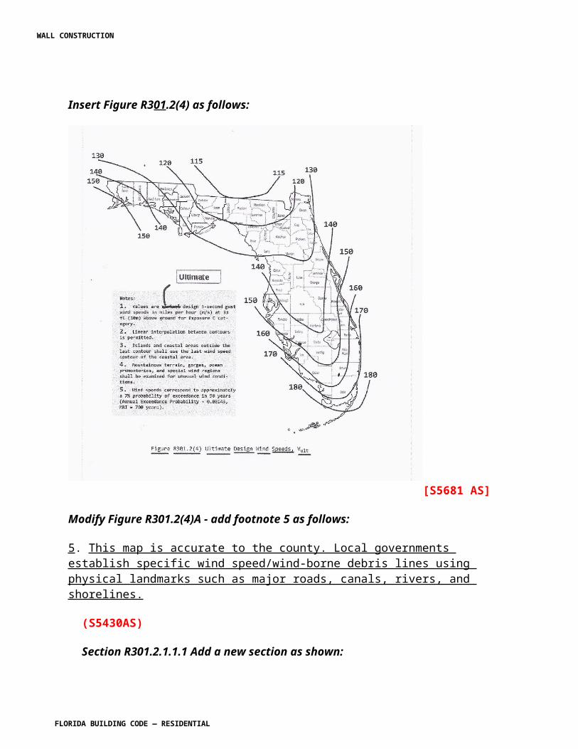
R315.1. Carbon monoxide alarms. Replace Section R315.1 to read as shown:
SECTION R315CARBON MONOXIDE ALARMS
R315.1 Carbon monoxide protection alarms . Every separate building or an addition to an existing building for which a permit for new construction is issued and having a fossil-fuel-burning heater or appliance, a fireplace, an attached garage, or other feature, fixture, or element that emits carbon monoxide as byproduct of combustion shall have an operational carbon monoxide alarm installed within 10 feet of each room used for sleeping purposes. For new construction, an approved carbon monoxide alarm shall be installed outside of each separate sleeping area in the immediate vicinity of the bedrooms in dwelling units within which fuel-fired appliances are installed and in dwelling units that have attached garages.
Exception: This section shall not apply to existing buildings that are undergoing alterations or repair unless the alteration is an addition as defined in Section R315.1.3.
R315.1.1 Carbon monoxide alarm. The requirements of Section R315.1 shall be satisfied by providing for one of the following alarm installations:
(1) A hard-wired carbon monoxide alarm.
(2) A battery-powered carbon monoxide alarm.
(3) A hard-wired combination carbon monoxide and smoke alarm.
(4) A battery-powered combination carbon monoxide and smoke alarm.
R315.1.2 Combination alarms. Combination smoke/carbon monoxide alarms shall be listed and labeled by a Nationally Recognized Testing Laboratory.
R315.1.3 Addition shall mean : An extension or increase in floor area, number of stories or height of a building or structure.
315.2 Carbon monoxide detection systems. Reserved. Carbon monoxide detection systems that include carbon monoxide detectors and audible notification appliances, installed and maintained in accordance with this section for carbon monoxide alarms and NFPA 720, shall be permitted. The carbon monoxide detectors shall be listed as complying with UL 2075. Where a household carbon monoxide detection system is installed, it shall become a permanent fixture of the occupancy, owned by the homeowner and shall be monitored by an approved supervising station.
Exception: Where carbon monoxide alarms are installed meeting the requirements of Section R315.1, compliance with Section 315.2 is not required.
WALL CONSTRUCTION
FLORIDA BUILDING CODE — RESIDENTIAL 7.40
R315.3 Where required in existing dwellings. Reserved . Where required in existing dwellings. Where work requiring a permit occurs in existing dwellings that have attached garages or in existing dwellings within which fuel-fired appliances exist, carbon monoxide alarms shall be provided in accordance with Section R315.1.
R315.4 Alarm requirements. Reserved. Single-station carbon monoxide alarms shall be listed as complying with UL 2034 and shall be installed in accordance with this code and the manufacturer’s installation instructions.
[F5438 AM R1]
Section R318 Protection against subterrannean termites . Replace with Florida specific criteria to read as shown:
SECTION R318PROTECTION AGAINST TERMITES
R318.1 Termite Protection. Termite protection shall be provided by registered termiticides, including soil applied pesticides, baiting systems, and pesticides applied to wood, or other approved methods of termite protection labeled for use as a preventative treatment to new construction. See §202, REGISTERED TERMITICIDE. Upon completion of the application of the termite protective treatment, a Certificate of Compliance shall be issued to the building department by the licensed pest control company that contains the following statement: "The building has received a complete treatment for the prevention of subterranean termites. Treatment is in accordance with rules and laws established by the Florida Department of Agriculture and Consumer Services."
R318.1.1 If soil treatment used for subterranean termite prevention, the initial chemical soil treatment inside the foundation perimeter shall be done after all excavation, backfilling and compaction is complete.R318.1.2If soil treatment is used for subterranean termite prevention, soil area disturbed after initial chemical soil treatment shall be retreated with a chemical soil treatment, including spaces boxed or formed.R318.1.3 If soil treatment is used for subterranean termite prevention, space in concrete floors boxed out or formed for the subsequent installation of plumbing traps, drains or any other purpose shall be created by using plastic or metal permanently placed forms of sufficient depth to eliminate any planned soil disturbance after initial chemical soil treatment.R318.1.4 If soil treatment is used for subterranean termite prevention, chemically treated soil shall be protected with a minimum 6 mil vapor retarder to protect against rainfall dilution. If rainfall occurs before vapor retarder placement, retreatment is required. Any work, including placement of reinforcing steel, done after chemical treatment until the concrete floor is poured, shall be done in such manner as to avoid penetrating or disturbing treated soil.
WALL CONSTRUCTION
FLORIDA BUILDING CODE — RESIDENTIAL 7.41
R318.1.5 If soil treatment is used for subterranean termite prevention, concrete overpour or mortar accumulated along the exterior foundation perimeter shall be removed prior to exterior chemical soil treatment, to enhance vertical penetration of the chemicals.R318.1.6 If soil treatment is used for subterranean termite prevention, chemical soil treatments shall also be applied under all exterior concrete or grade within 1 foot (305 mm) of the primary structure sidewalls. Also, a vertical chemical barrier shall be applied promptly after construction is completed, including initial landscaping and irrigation/sprinkler installation. Any soil disturbed after the chemical vertical barrier is applied shall be promptly retreated.R318.1.7 If a registered termiticide formulated and registered as a bait system is used for subterranean termite prevention, §R318.1.1 through §R318.1.6 do not apply; however, a signed contract assuring the installation, maintenance and monitoring of the baiting system for a minimum of five years from the issue of the Certificate of Occupancy shall be provided to the building official prior to the pouring of the slab, and the system must be installed prior to final building approval.
If the baiting system directions for use require a monitoring phase prior to installation of the pesticide active ingredient, the installation of the monitoring phase components shall be deemed to constitute installation of the system.R318.1.8 If a registered termiticide formulated and registered as a wood treatment is used for subterranean termite prevention, Sections R318.1.1 through R318.1.6 do not apply. Application of the wood treatment termiticide shall be as required by label directions for use, and must be completed prior to final building approval.
R318.2 Penetration. Protective sleeves around piping penetrating concrete slab-on-grade floors shall not be of cellulose-containing materials. If soil treatment is used for subterranean termite protection, the sleeve shall have a maximum wall thickness of 0.010 inch (0.25 mm), and be sealed within the slab using a non-corrosive clamping device to eliminate the annular space between the pipe and the sleeve. No termiticides shall be applied inside the sleeve.
R318.3 Cleaning. Cells and cavities in masonry units and air gaps between brick, stone or masonry veneers and the structure shall be cleaned of all non-preservative treated or non-naturally durable wood, or other cellulose-containing material prior to concrete placement.
Exception: Inorganic material manufactured for closing cells in foundation concrete masonry unit construction or clean earth fill placed in concrete masonry unit voids below slab level before termite treatment is performed.
R318.4 Concrete bearing ledge. Brick, stone or other veneer shall be supported by a concrete bearing ledge at least equal to the total thickness of the brick, stone or other veneer which is poured integrally with the concrete foundation. No supplemental concrete foundation pours which will create a hidden cold joint shall be used without supplemental treatment in the foundation unless there is an approved physical barrier. An approved physical barrier shall also be installed from below the wall sill plate or first block course horizontally to embed in a mortar joint. If masonry veneer extends below grade, a termite protective treatment must be applied to the cavity created between the veneer and the foundation, in lieu of a physical barrier.
Exception: Veneer supported by a structural member secured to the foundation sidewall in accordance with ACI 530/ASCE 5/TMS 402, provided at least a 6 inch (152 mm) clear
WALL CONSTRUCTION
FLORIDA BUILDING CODE — RESIDENTIAL 7.42
inspection space of the foundation sidewall exterior exist between the veneer and the top of any soil, sod, mulch or other organic landscaping component, deck, apron, porch, walk or any other work immediately adjacent to or adjoining the structure.
R318.5 Protection against decay and termites. Condensate Lines, irrigation/sprinkler system risers for spray heads, and roof downspouts shall discharge at least 1 foot (305 mm) away from the structure sidewall, whether by underground piping, tail extensions or splash blocks. Gutters with downspouts are required on all buildings with eaves of less than 6 inches (152 mm) horizontal projection except for gable end rakes or on a roof above another roof.
R318.6 Preparation of building site and removal of debris.R318.6.1 All building sites shall be graded to provide drainage under all portions of the building not occupied by basements.R318.6.2 The foundation and the area encompassed within 1 foot (305 mm) therein shall have all vegetation, stumps, dead roots, cardboard, trash and foreign material removed and the fill material shall be free of vegetation and foreign material. The fill shall be compacted to assure adequate support of the foundation.R318.6.3 After all work is completed, loose wood and debris shall be completely removed from under the building and within 1 foot (305 mm) thereof. All wood forms and supports shall be completely removed. This includes, but is not limited to: wooden grade stakes, forms, contraction spacers, tub trap boxes, plumbing supports, bracing, shoring, forms or other cellulose-containing material placed in any location where such materials are not clearly visible and readily removable prior to completion of the work. Wood shall not be stored in contact with the ground under any building.
[Florida specific]
Add new Section R318.7 as shown:
R318.7 Inspection for termites. In order to provide for inspection for termite infestation, clearance between exterior wall coverings and final earth grade on the exterior of a building shall not be less than 6 inches (152 mm).
Exceptions:l. Paint or decorative cementitious finish less than 5/8 inch (17.1 mm) thick adhered directly to the masonry foundation sidewall.2. Access or vehicle ramps which rise to the interior finish floor elevation for the width of such ramps only.3. A 4-inch (102 mm) inspection space above patio and garage slabs and entry areas.4. If the patio has been soil treated for termites, the finish elevation may match the building interior finish floor elevations on masonry construction only.5. Masonry veneers constructed in accordance with Section R318.4.
[SP5416 AS]
WALL CONSTRUCTION
FLORIDA BUILDING CODE — RESIDENTIAL 7.43
SECTION R320ACCESSIBILITY
Section R320.1 Scope. Revise to read as shown:
R320.1 Scope. Shall be in accordance with the provisions of the Florida Building Code, Accessibility. Where there are four or more dwelling units or sleeping units in a single structure, the provisions of Chapter 11 of the International Building Code for Group R-3 shall apply.
R320.1.1 All new single-family houses, duplexes, triplexes, condominiums and townhouses shall provide at least one bathroom, located with maximum possible privacy, where bathrooms are provided on habitable grade levels, with a door that has a 29-inch (737 mm) clear opening. However, if only a toilet room is provided at grade level, such toilet rooms shall have a clear opening of not less than 29 inches (737 mm).
[A5439 AS]
Section R321.3 Accessibility. Revise to read as shown:
R321.3 Accessibility. Reserved. Elevators or platform lifts that are part of an accessible route required by Chapter 11 of the International Building Code, shall comply with ICC A117.1.
[A5440 AS]
R322.1.1 Alternative provisions. Revise to read as shown:
R322.1.1 Alternative provisions. As an alternative to the requirements in Section R322, R322.3 for buildings and structures located in whole or in part in coastal high-hazard areas (V Zones) and Coastal A Zones, if delineated, ASCE 24 is permitted subject to the limitations of this code and the limitations therein. [SP 5292 AS]
Section R322.1.7 Protection of water supply and sanitary sewage systems. Revise to read as shown:
R322.1.7 Protection of water supply and sanitary sewage systems. New and replacement water supply systems shall be designed to minimize or eliminate infiltration of flood waters into the systems in accordance with the plumbing provisions of this code. New and replacement sanitary sewage systems shall be designed to minimize or eliminate infiltration of floodwaters into systems and discharges from systems into floodwaters in accordance with the plumbing provisions of this code and in accordance with Chapter 64E-6, Florida Administrative Code,
WALL CONSTRUCTION
FLORIDA BUILDING CODE — RESIDENTIAL 7.44
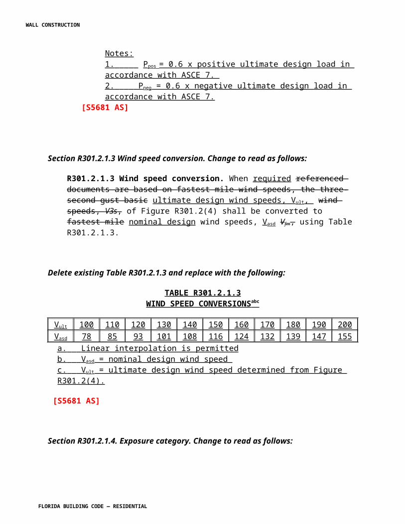
Standards for Onsite Sewage Treatment and Disposal Systems. and Chapter 3 of the International Private Sewage Disposal Code.
Section R322.1.9 Manufactures homes. Revise to read as shown:
R322.1.9 Manufactured homes. In addition to the applicable requirements of the state agency with jurisdiction over installation of manufactured homes, installation of manufactured homes in flood hazard areas is subject to the applicable provisions of the local floodplain management ordinance.
Section R322.1.11 Structural seaward of a coastal construction line. Add section to read as shown:
R322.1.11 Structures seaward of a coastal construction line. In addition to the requirements of this section, structures located in flood hazard areas and seaward of the coastal construction line shall be designed to resist the predicted forces of a 100-year storm event in accordance with Section R3109 of the Florida Building Code, Building, and the more restrictive provisions shall govern.
Section R322.2.4 Pools in flood hazard areas. Add to read as shown:
R322.2.4 Pools in flood hazard areas. Pools that are located in flood hazard areas established by Table R301.2(1), including above-ground pools, on-ground pools, and in-ground pools that involve placement of fill, shall comply with Sections R322.2.4.1 or RB322.2.4.2.
Exception: Pools located in riverine flood hazard areas which are outside of designated floodways.
R322.2.4.1 Pools located in designated floodways. Where pools are located in designated floodways, documentation shall be submitted to the building official, which demonstrates that the construction of the pool will not increase the design flood elevation at any point within the jurisdiction.
R322.2.4.2 Pools located where floodways have not been designated. Where pools are located in riverine flood hazard areas where design flood elevations are specified but floodways have not been designated, the applicant shall provide a floodway analysis that demonstrates that the proposed pool will not increase the design flood elevation more than 1 foot (305 mm) at any point within the jurisdiction.
[SP5294 AS]
WALL CONSTRUCTION
FLORIDA BUILDING CODE — RESIDENTIAL 7.45
Section R322.3.2 Elevation requirements. Revise to read as shown:
R322.3.2 Elevation requirements.
1. All buildings and structures erected within coastal high-hazard areas shall be elevated so that the lowest portion of all structural members supporting the lowest floor, with the exception of piling, pile caps, columns, grade beams and bracing, is elevated to or above the design flood elevation. :
1.1. Located at or above the design flood elevation, if the lowest horizontal structural member is oriented parallel to the direction of wave approach, where parallel shall mean less than or equal to 20 degrees (0.35 rad) from the direction of approach, or
1.2. Located at the base flood elevation plus 1 foot (305 mm), or the design flood elevation, whichever is higher, if the lowest horizontal structural member is oriented perpendicular to the direction of wave approach, where perpendicular shall mean greater than 20 degrees (0.35 rad) from the direction of approach.
2. – 4. [No change]
[SP 5295 AS]
Section R322.3.3.1 Pools. Add new section to read as shown:
R322.3.3.1 Pools. Pools in coastal high-hazard areas shall be designed and constructed in conformance with ASCE 24.
[SP5294 AS]
Section R322.3.4 Walls below design flood elevation. Revise to read as shown:
R322.3.4 Walls below design flood elevation. Walls and partitions are permitted below the elevated floor, provided that such walls and partitions are not part of the structural support of the building or structure and:
1. Electrical, mechanical, and plumbing system components are not to be mounted on or penetrate through walls that are designed to break away under flood loads; and2. Are constructed with insect screening or open lattice; or
3. Are designed to break away or collapse without causing collapse, displacement or other structural damage to the elevated portion of the building or supporting foundation system. Such walls, framing and connections shall have a design safe loading resistance of not less than 10 (479 Pa) and no more than 20 pounds per square foot (958 Pa) determined using allowable stress design; or
WALL CONSTRUCTION
FLORIDA BUILDING CODE — RESIDENTIAL 7.46
4. Where wind loading values of this code exceed 20 pounds per square foot (958 Pa) determined using allowable stress design, the construction documents shall include documentation prepared and sealed by a registered design professional that:
4.1 – 4.2 [No change]
[SP5296 AS]
Section R324. Add a new section to read as shown:
SECTION R324AIRPORT NOISE
R324.1 Airport noise study guidelines . The Aviation Safety and Noise Abatement Act of 1979 14 CFR Part 150 (US Department of Transportation) including revisions through January 2005 and hereby adopted as a guideline for establishing airport noise control. When required by a local government by local ordinance to provide noise attenuation in a new structure or addition to an existing structure near an airport in the area of the local government, the applicant must provide either:
1. A testing certificate from an accredited noise testing lab that a new structure or addition to existing structure built to the submitted engineering plans will achieve an average minimum dBA reduction equal to or greater than the reduction required,2. An engineering judgment signed and sealed by an engineer licensed in the State of Florida that the structure or addition built to the submitted engineering plans will achieve an average minimum dBA reduction equal to or greater than the reduction required, or 3. Plans using the standards contained in "Guidelines for Sound Insulation of Residences Exposed to Aircraft Operations" prepared for the Department of the Navy by Wyle Research and Consulting, Arlington, Virginia, April 2005 on file with the Florida Building Commission.
[S5441 AS]
WALL CONSTRUCTION
FLORIDA BUILDING CODE — RESIDENTIAL 7.47
CHAPTER 4, FOUNDATIONS
Section R401.1 Application. Revise text to add exception 3 to read as shown:
R401.1 Application. The provisions of this chapter shall control the design and construction of the foundation and foundation spaces for all buildings. In addition to the provisions of this chapter, the design and construction of foundations in flood hazard areas as established by Table R301.2(1) shall meet the provisions of Section R322. Wood foundations shall be designed and installed in accordance with AF&PA PWF.
Exception: The provisions of this chapter shall be permitted to be used for wood foundations only in the following situations: 1. – 2. [No change]3. Buildings and structures located within the High-Velocity Hurricane Zone shall comply with the provisions of Chapter 44 and, as applicable, Section R322 in flood hazard areas .
[Florida specific]
Section R401.2 Requirements. Revise to read as shown:
R401.2 Requirements. Foundations shall be capable of resisting all loads from roof uplift and building overturn. Foundation uplift for light-frame wood or steel buildings shall be calculated or determined from Table R401.1. Masonry buildings within the dimensional scope of Table R401.1 shall be assumed to be of adequate weight so as not to require uplift resistance greater than that provided by the structure and any normal foundation. Foundation construction shall also be capable of accommodating all gravity loads according to Section R301 and of transmitting the resulting loads to the supporting soil. Fill soils that support footings and foundations shall be designed, installed and tested in accordance with accepted engineering practice. Gravel fill used as footings for wood and precast concrete foundations shall comply with Section R403.
WALL CONSTRUCTION
FLORIDA BUILDING CODE — RESIDENTIAL 7.48
TABLE R401.1
FOUNDATION UPLIFT LIGHT STEEL & WOOD FRAME BUILDINGS IN EXPOSURE B (plf) 5, 6
Roof Angle
Bldg Width
Minimum Building Length
Vasd as determined in accordance with Section R301.2.1.3 / Velocity Pressure
100 110 120 130 140 15015 18 22 26 30 34
45
3 Stories 3
20 12 173 276 389 512 644 78725 14 73 165 265 374 492 61830 19 0 81 174 275 384 50235 25 17 48 104 200 305 41740 35 33 69 109 152 240 349
2 Stories 2
20 12 64 126 195 270 350 43725 15 17 66 129 198 272 35230 22 38 62 90 146 217 29435 35 56 86 118 154 192 25240 40 74 108 146 186 230 277
1 Story 1
20 12 33 46 61 94 132 17325 22 57 75 96 118 142 16730 18 79 103 129 157 187 21935 16 100 128 159 192 229 26740 16 120 152 188 226 268 312
30
3 Stories 3
20 12 92 177 271 373 483 60125 17 0 63 143 230 324 42530 25 0 23 52 125 209 30035 35 13 44 78 115 154 20640 40 28 64 102 145 190 239
2 Stories 2
20 13 1 50 103 162 224 29225 23 16 35 57 84 139 19930 30 36 60 87 116 148 18135 35 54 83 115 150 187 22740 36 71 104 141 181 224 27020 20 32 46 60 76 93 11225 15 56 74 95 117 140 16630 13 78 102 127 155 185 21735 14 99 127 157 190 226 264
1Story 1 40 16 118 150 185 223 264 308
20 12 113 203 301 408 523 64725 14 45 130 222 322 431 54730 17 4 85 177 277 385 50135 19 20 58 154 257 369 489
3Story 1 40 21 35 72 141 249 367 493
WALL CONSTRUCTION
FLORIDA BUILDING CODE — RESIDENTIAL 7.49
20 12 43 100 163 231 304 38425 13 22 79 143 214 289 37130 15 42 72 141 217 298 38635 15 61 92 150 232 321 417
2Story 1 40 16 78 114 164 254 352 45720 12 38 57 94 135 179 22625 12 62 82 122 171 223 28030 12 85 110 154 212 275 34235 14 107 136 190 257 330 409
1Story 1 40 16 126 160 227 304 388 478
TABLE R401.1
FOUNDATION UPLIFT LIGHT STEEL & WOOD FRAME BUILDINGS IN EXPOSURE C (plf) 5, 6
Roof Angle
Bldg Width
Minimum Building Length 4
Vasd as determined in accordance with Section R301.2.1.3 / Velocity Pressure
100 110 120 130 140 15021 26 31 36 42 48
45
3 Stories 3
20 12 370 515 673 845 1031 123125 13 249 377 518 670 836 101330 17 159 278 408 550 703 86735 21 89 203 328 463 610 76740 26 102 153 262 394 537 691
2 Stories 2
20 12 184 271 368 472 585 70625 13 119 200 288 385 489 60130 18 85 147 233 326 426 53335 24 113 155 200 284 383 48940 36 139 187 240 297 358 457
1 Story 1
20 12 58 95 140 189 243 30025 16 92 118 147 178 224 28130 19 124 157 193 233 275 32135 17 154 193 236 283 334 38840 16 182 227 277 331 389 452
30 3 Stories 3 20 12 256 376 507 650 804 970
25 15 130 232 344 466 598 74030 21 47 127 228 337 455 58235 31 72 116 163 241 351 46940 40 96 146 200 259 323 392
WALL CONSTRUCTION
FLORIDA BUILDING CODE — RESIDENTIAL 7.50
2 Stories 2
20 12 95 163 238 320 408 50225 18 53 85 151 223 301 38530 30 83 117 154 195 239 30435 35 110 150 195 244 296 35340 37 135 182 233 289 350 415
1 Story 1
20 20 58 76 97 119 143 16925 16 91 117 145 176 210 24530 13 123 156 191 230 272 31735 14 152 191 234 280 330 38440 16 179 224 273 327 384 446
20
3 Stories 3
20 12 285 411 549 698 860 103425 13 207 325 455 595 748 91130 15 162 280 409 549 701 86335 17 138 260 393 538 695 86340 18 124 252 392 545 709 886
2 Stories 2
20 12 152 233 320 416 519 63025 12 133 215 306 404 511 62530 13 130 219 316 422 536 65835 14 138 235 341 456 581 71540 16 150 257 373 500 636 783
1 Story 1
20 12 88 136 188 245 307 37325 12 114 172 235 303 377 45730 12 146 214 288 370 457 55235 14 180 259 346 441 543 65340 16 215 306 406 515 632 758
Notes:
1. Based on 1 st floor height = 10 ft. or 11 ft. floor to floor in multi-story. 2. Based on 2 nd floor height = 8 ft. or 9 ft. floor to floor in multi-story. 3. Based on 3 rd floor height = 8 ft. 4. Building length shall be equal to or greater than that shown in tables. 5. Roof and floor framing shall span in the same direction. 6. Includes provision for 2 foot roof overhang
(S5780 AS)
Section R403.1 General. Revise to read as shown:
R403.1 General. [No change to text]
WALL CONSTRUCTION
FLORIDA BUILDING CODE — RESIDENTIAL 7.51
R403.1.1 Minimum size. Minimum sizes for concrete and masonry footings shall be as set forth in Table R403.1 and Figure R403.1(1). Minimum sizes for concrete and masonry footings shall also be as required to provide adequate resistance to uplift and overturn of the building as determined from Table 401.1 or as calculated using engineered design in accordance with the Florida Building Code, Building. The footing width, W, shall be based on the load-bearing value of the soil in accordance with Table R401.4.1. Spread footings shall be at least 8 inches (203 mm) in thickness T. Footing projections, P, shall be at least 2 inches (51 mm) and shall not exceed the thickness of the footing. The size of footings supporting piers and columns shall be based on the tributary load and allowable soil pressure in accordance with Table R401.4.1. Footings for wood foundations shall be in accordance with the details set forth in Section R403.2, and Figures R403.1(2) and R403.1(3).
R403.1.2 Resistance to uplift. Uplift resistance of common foundations are given in Table R403.1.2. Uplift resistance of these foundations may be increased by increasing the size of the concrete footing. When determining the modified uplift resistance the added weight shall be reduced by multiplying by a factor of 0.6. Other foundation systems shall be engineered in accordance with the Florida Building Code, Building .
TABLE R403.1.2
FOUNDATION UPLIFT DESIGN DETAILS
FOOTING TYPE T W SLAB/WALL 1 RESISTANCE NOTESA Mono 20 12 6 502 3
Mono 20 16 6 585 3B Mono Interior 20 12 13 796 3
Mono Interior 20 16 13 879 3C 12” Stem/Joist 10 20 228 436 1,2,3D Mono 20 12 6 502 --
Mono 20 16 6 585 --E Mono Interior 20 12 13 796 --
Mono Interior 20 16 13 879 --F Stem/Joist 10 20 -- 208 2,3G Stem/Slab 10 20 6 460 3H Stem/Slab 10 12 6 377 3
Stem/Slab 10 20 6 460 3For SI: 1 inch = 25.4 mm.1. Tributary width of 3½" slab or weight of stemwall and bond beam2. 1st floor dead load multiplied by 0.6 may also be included.3. All footing dowel bars shall be same size as wall steel, shall have a standard 90-degree hook, and shall be embedded a minimum of 6 inches. Dowel bars shall lap vertical wall reinforcement a minimum of 25 inches.
WALL CONSTRUCTION
FLORIDA BUILDING CODE — RESIDENTIAL 7.52
Delete Figure R403.1(1) and replace with the following:
FOOTING A MONOLITHIC SLAB-ON-GRADE EXTERIOR WALL
FOOTING B MONOLITHIC SLAB-ON-GRADE INTERIOR WALL
FIGURE 403.1(1) CONCRETE AND MASONRY FOUNDATION DETAILS
WALL CONSTRUCTION
FLORIDA BUILDING CODE — RESIDENTIAL 7.53
FOOTING C STEM WALL WOOD JOIST FLOOR
FIGURE R403.1(1)—continued
WALL CONSTRUCTION
FLORIDA BUILDING CODE — RESIDENTIAL 7.54
FOOTING D MONOLITHIC EXTERIOR FOOTING
FOOTING E MONOLITHIC INTERIOR FOOTING
FIGURE R403.1(1)—continued
WALL CONSTRUCTION
FLORIDA BUILDING CODE — RESIDENTIAL 7.55
FOOTING F WOOD FLOOR TO CONCRETE OR MASONRY STEMWALL
FIGURE R403.1(1)—continued
WALL CONSTRUCTION
FLORIDA BUILDING CODE — RESIDENTIAL 7.56
FOOTING G STEMWALL FOUNDATION WITH SLAB ON GRADE
FIGURE R403.1(1)—continued
WALL CONSTRUCTION
FLORIDA BUILDING CODE — RESIDENTIAL 7.57
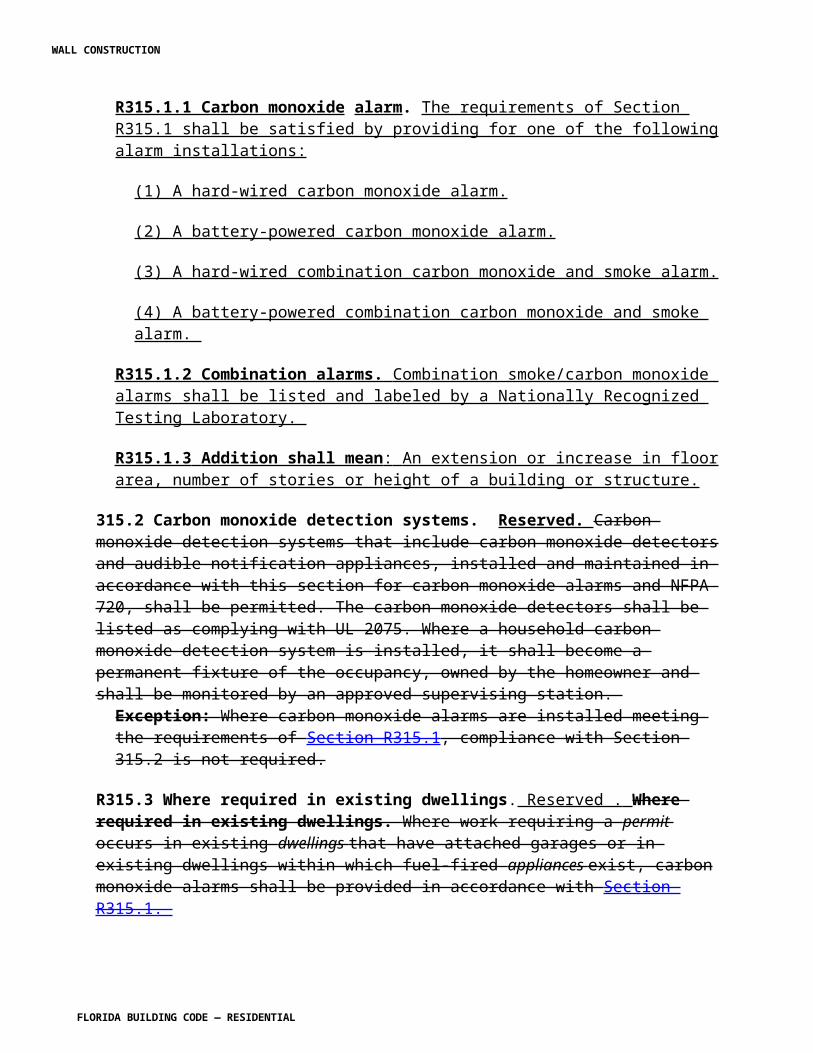
FOOTING H
FIGURE R403.1(1)—continued
[S5780 AS]
WALL CONSTRUCTION
FLORIDA BUILDING CODE — RESIDENTIAL 7.58
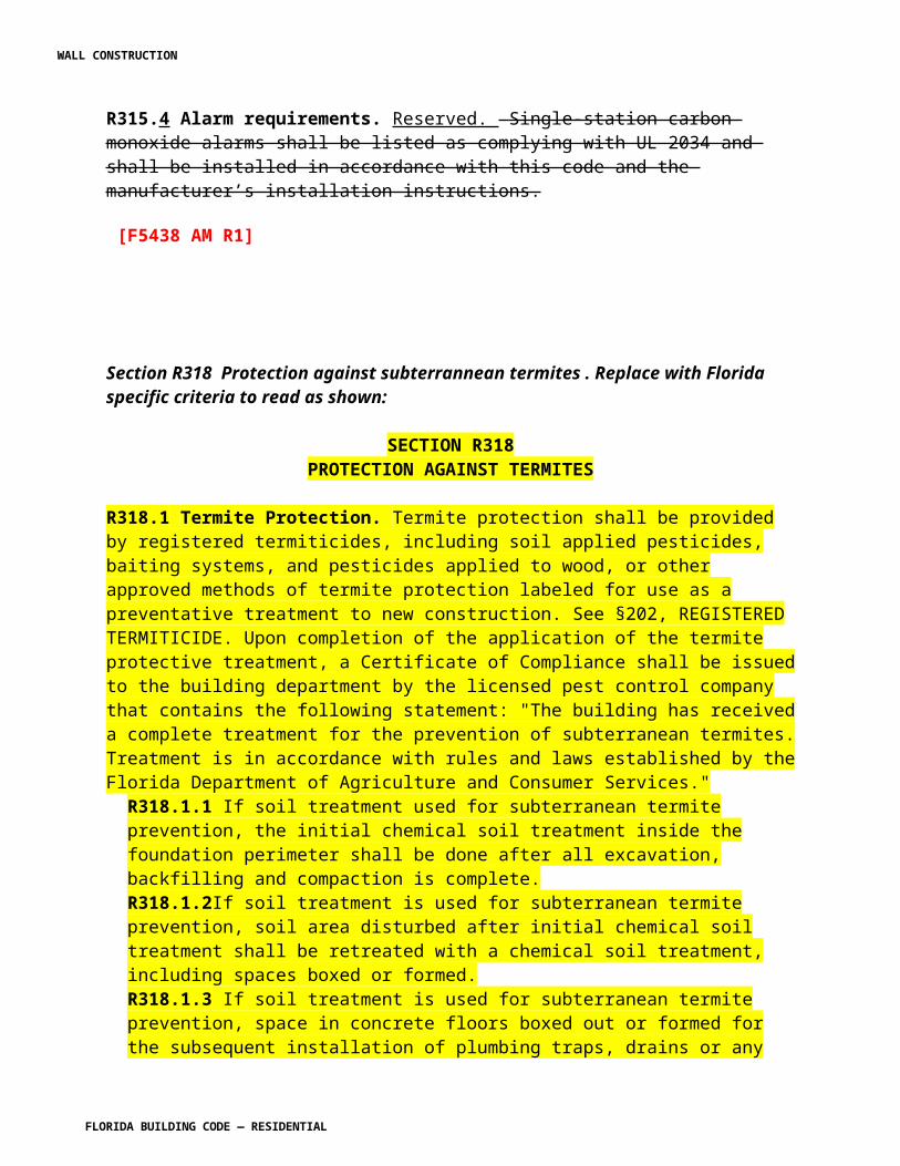
CHAPTER 5, FLOORS
R501.1 Application. Change to read as follows:
R501.1 Application. The provisions of this chapter shall control the design and construction of the floors for all buildings including the floors of attic spaces used to house mechanical and/or plumbing fixtures and equipment.
Exception: Buildings and structures located within the High-Velocity Hurricane Zone shall comply with the provisions of Chapter 44.
Section 502.1. Add the following sections R502.1.8 through R502.1.11 as shown using IRC sections identified in brackets:
R502.1.8 [IRC502.12] Draftstopping required. Draftstopping shall be provided in accordance with Section R302.12.
R502.1.9 [IRC502.13] Fireblocking required. Fireblocking shall be provided in accordance with Section R302.11.
R502.1.10 [IRC502.11] Wood trusses
R502.1.10.1 [IRC502.11.1] Design. Wood trusses shall be designed in accordance with approved engineering practice. The design and manufacture of metal plate connected wood trusses shall comply with ANSI/TPI 1. The truss design drawings shall be prepared by a registered professional where required by Florida Statutes. the statutes of the jurisdiction in which the project is to be constructed in accordance with Section R106.1.
R502.1.10.2 [IRC502.11.2] Bracing. Trusses shall be braced to prevent rotation and provide lateral stability in accordance with the requirements specified in the construction documents for the building and on the individual truss design drawings. In the absence of specific bracing requirements, trusses shall be braced in accordance with TPI/WTCA BCSI accepted industry practices , such as the Building Component Safety Information (BCSI) Guide to Good Practice for Handling, Installing & Bracing of Metal Plate Connected Wood Trusses.
R502.1.10.3 [IRC502.11.3] Alterations to trusses. [No change to text].
R502.1.10.4 [IRC502.11.4] Truss design drawings. Truss design drawings, prepared in compliance with Section R502.1.3.1, shall be provided to the building official and approved prior to installation. Truss design drawing shall be provided with the shipment of trusses
WALL CONSTRUCTION
FLORIDA BUILDING CODE — RESIDENTIAL 7.59
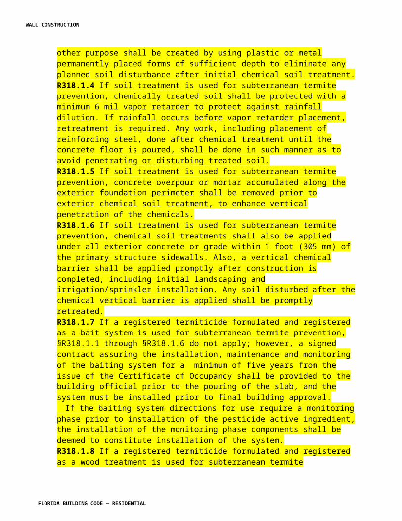
delivered to the job site. Truss design drawings shall include, at a minimum, the information specified below: [No change to remainder of text]
R502.1.11 [IRC502.8] Cutting, drilling and notching. Structural floor members shall not be cut, bored or notched in excess of the limitations specified in this section. See Figure R502.1.11 R502.8.
FIGURE R502.1.11 [IRC502.8]CUTTING, NOTCHING and DRILLING.
[No other change to IRC Figure R502.8]
R502.1.11.1 [IRC502.8.1] Sawn lumber. [No change to IRC R502.8.1 text]
R502.1.11.2 [IRC502.8.2] Engineered wood products. [No change to IRC R502.8.2 text]
Section R502.2 Design and construction. Revise to read as shown:
R502.2 Design and construction. Floor framing of light-frame wood construction shall be designed and constructed in accordance with the provisions of Section R301.2.1.1 or in accordance with the AF&PA NDS. Floor framing of light-frame wood construction shall also comply with Sections R319, R320, and R502.1. Floors shall be designed and constructed in accordance with the provisions of this Chapter, Figure R502.2 and Sections R317 and R318 or in accordance with AF&PA/ NDS.
The remainder of Section R502.2 is to be deleted and "Reserved."
[S5984 AS]
Section R505 Steel Floor Framing. Reserve as shown:
SECTION R505STEEL FLOOR FRAMING
RESERVED
[S6000 AS]
CHAPTER 6, WALL CONSTRUCTION
Section R601.1 Application. Revise to read as shown:
WALL CONSTRUCTION
FLORIDA BUILDING CODE — RESIDENTIAL 7.60
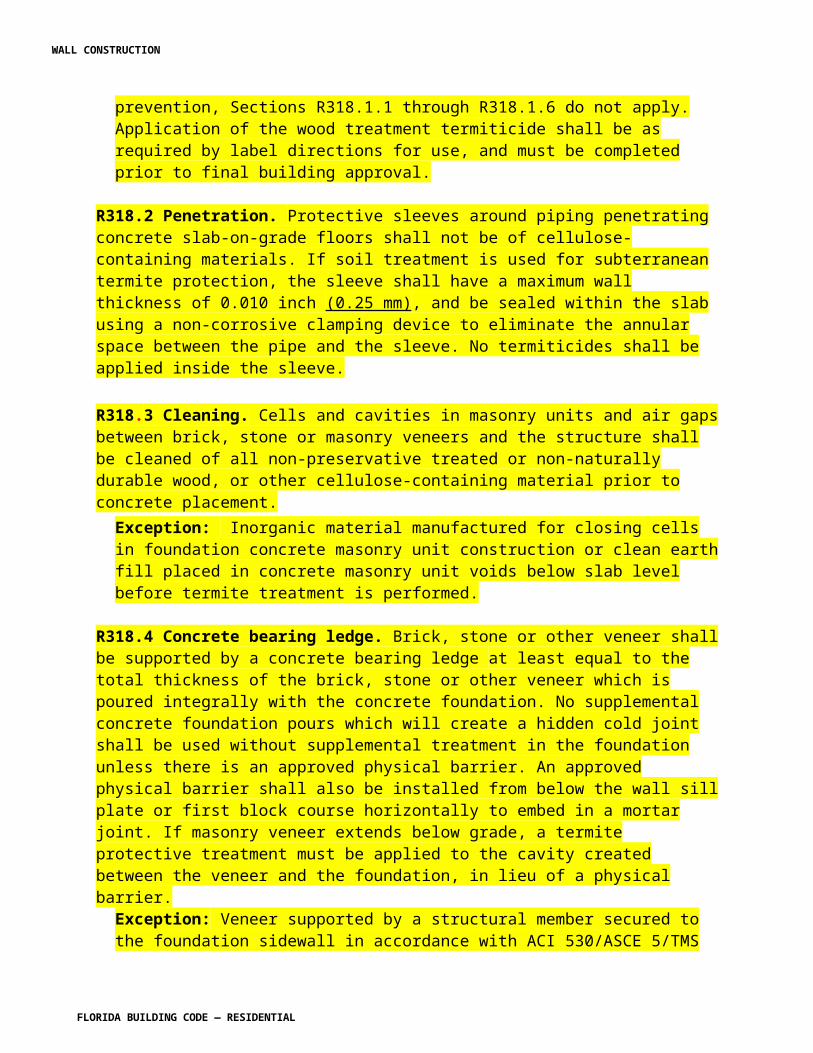
R601.1 Application. The provisions of this chapter shall control the design and construction of all walls and partitions for all buildings.
Exception: Buildings and structures located within the High-Velocity Hurricane Zone shall comply with the provisions of Chapter 44.
[S4972 AS]
Section 602.2. Revise Section R602.2 and add the following sections R602.2.2.1 through R602.2.3.1 as shown using IRC sections identified in brackets:
R602.2 General requirements Grade. Studs shall be a minimum No. 3, standard or stud grade lumber. Exception: Bearing studs not supporting floors and nonbearing studs may be utility grade lumber, provided the studs are spaced in accordance with Table R602.3(5).
R602.2.1 [IRC602.8] Fireblocking required. Fireblocking shall be provided in accordance with Section R302.11.
R602.2.2 [IRC602.7.3] Nonbearing walls. Load-bearing headers are not required in interior or exterior nonbearing walls. A single flat 2-inch-by-4-inch (51 mm by 102 mm) member may be used as a header in interior or exterior nonbearing walls for openings up to 8 feet (2438 mm) in width if the vertical distance to the parallel nailing surface above is not more than 24 inches (610 mm). For such nonbearing headers, no cripples or blocking are required above the header.
R602.2.2.1 [IRC602.5] Interior nonbearing walls. Interior nonbearing walls shall be permitted to be constructed with 2-inch-by-3-inch (51 mm by 76 mm) studs spaced 24 inches (610 mm) on center or, when not part of a braced wall line, 2-inch-by-4-inch (51 mm by 102 mm) flat studs spaced at 16 inches (406 mm) on center. Interior nonbearing walls shall be capped with at least a single top plate. Interior nonbearing walls shall be fireblocked in accordance with Section R302.11 R602.8.
R602.2.3 [IRC602.6] Drilling and notching--studs. Drilling and notching of studs shall be in accordance with the following:
1. Notching. Any stud in an exterior wall or bearing partition may be cut or notched to a depth not exceeding 25 percent of its width. Studs in nonbearing partitions may be notched to a depth not to exceed 40 percent of a single stud width.
2. Drilling. Any stud may be bored or drilled, provided that the diameter of the resulting hole is no more than 60 percent of the stud width, the edge of the hole is no more than 5/8 inch (16 mm) to the edge of the stud, and the hole is not located in the same section as a cut or notch. Studs located in exterior walls or bearing partitions drilled over 40 percent and up to 60 percent shall also be doubled with no more than two successive doubled studs bored. See Figures R602.2.3(1) and R602.2.3(2) [IRC Figures R602.6(1) and R602.6(2)].
WALL CONSTRUCTION
FLORIDA BUILDING CODE — RESIDENTIAL 7.61
Exception: Use of approved stud shoes is permitted when they are installed in accordance with the manufacturer’s recommendations.
R602.2.3.1 [IRC602.6.1] Drilling and notching of top plate. When piping or ductwork is placed in or partly in an exterior wall or interior load-bearing wall, necessitating cutting, drilling or notching of the top plate by more than 50 percent of its width, a galvanized metal tie not less than 0.054 inch thick (1.37 mm) (16 ga) and 11/2 inches (38 mm) wide shall be fastened across and to the plate at each side of the opening with not less than eight 10d (0.148 inch diameter) having a minimum length of 1½ inches (38 mm) at each side or equivalent. The metal tie must extend a minimum of 6 inches past the opening. See Figure R602.2.3.1 [IRC Figure R602.6.1].
Exception: When the entire side of the wall with the notch or cut is covered by wood structural panel sheathing.
Section R602.3 Design and construction. Revise to read as shown:
R602.3 Design and construction. Exterior walls of light-frame wood construction shall be designed and constructed in accordance with the provisions of Section R301.2.1.1 or in accordance with the AF&PA NDS. Exterior walls of light-frame wood construction shall also comply with Section R602.1. and R602.2 . this chapter and Figures R602.3(1) and R602.3(2) or in accordance with AF&PA’s NDS. Components of exterior walls shall be fastened in accordance……..purposes shall comply with Section R703.
The remainder of Section R602.3 and sections R602.4 through R602.12 are to be deleted and "Reserved."
[S5986 AS]
Section R603 STEEL WALL FRAMING. Delete text and reserve as shown:
SECTION R603STEEL WALL FRAMING
RESERVED
[S6001 AS]
SECTIONS R606.2, R606.5, R606, R607 AND 609. REVISE AS SHOWN IN SEPARATE FILE.
WALL CONSTRUCTION
FLORIDA BUILDING CODE — RESIDENTIAL 7.62
[S6017 AS]
Section R606.16. Add a new section to read as shown:
R606.16 Masonry Opening Tolerances. Masonry rough openings may vary in the cross section dimension or elevation dimension specified on the approved plans from - 1/4 inches (6.4 mm) to + 1/2 inches (12.7 mm). For exterior window and door installation provisions see Sections R612.11 and R612.12.
[S5950 AS]
Section R612.1. Change to read as shown: R612.1 General. This section prescribes performance and construction requirements for exterior windows and doors installed in walls. Windows and doors shall be installed and flashed in accordance with the fenestration manufacturer’s written installation instructions. Window and door openings shall be flashed in accordance with Section R703.8. Written installation instructions shall be provided by the fenestration manufacturer for each window or door.
(S5769 AM R1)
Section R612.2 Performance. Revise to read as shown:
R612.2 Performance. Exterior windows and doors shall be designed to resist the design wind loads specified in Table R301.2(2) adjusted for height and exposure per Table R301.2(3). For testing required in Sections R612.3 and R612.5, design pressures determined from Table R301.2(2) or ASCE 7 are permitted to be multiplied by 0.6. [S5701 AS] (S5953 AM R1)
Section R612.3 Testing and labeling. Revise [Add a new section] to read as shown:
R612.3 Testing and labeling. Exterior windows and sliding doors shall be tested by an approved independent laboratory, and bear a label identifying manufacturer, performance characteristics and approved inspection agency to indicate compliance with AAMA/WDMA/CSA 101/I.S.2/A440. Exterior side-hinged doors shall be tested and labeled as conforming to AAMA/WDMA/CSA 101/I.S.2/A440 or comply with Section R612.5.
Exception: Decorative glazed openings.
R612.3.1 Comparative analysis. Change to read as shown:
WALL CONSTRUCTION
FLORIDA BUILDING CODE — RESIDENTIAL 7.63
R612.3.1 Comparative analysis. Structural wind load design pressures for window and door units smaller other than the size tested in accordance with Section R612.3 shall be permitted to be higher different than the design value of the tested unit provided such higher different pressures are determined by accepted engineering analysis or validated by an additional test of the window or door unit to the different design pressure in accordance with section R612.3. All components of the small alternative size unit shall be the same as the tested or labeled unit. Where such calculated design pressures are used, they shall be validated by an additional test of the window unit having the highest allowable design pressure.
Exceptions:
i Operable windows and doors rated in this manner shall comply with the following:
1. The frame area of the alternate size unit shall not exceed the frame area of the tested approved unit.
2. Shall vary from the tested approved unit only in width, height or load requirements.
3. Shall not exceed 100 percent of the proportional deflection for fiber stress of the intermediate members of the approved unit.
4. Shall not exceed 100 percent of the concentrated load at the juncture of the intermediate members and the frame of the approved unit.
5. Shall not exceed the air and water infiltration resistance of the tested approved unit.
6. Shall not exceed the maximum cyclic pressure of the tested approved unit when tested per TAS 201 and TAS 203 or ASTM E 1886 and ASTM E 1996 where applicable.
ii. Non-operable windows and doors rated in this manner shall comply with the following:
1. The frame area of the alternate size unit shall not exceed the frame area of the tested approved unit.
2. Shall vary from the tested approved unit only in width, height or load requirements.
3. The maximum uniform load distribution (ULD) of any side shall be equal to the uniform load carried by the side divided by the length of the side.
4. The ULD of any member shall not exceed the ULD of the corresponding member of the tested approved unit.
5. The ULD of each member shall be calculated in accordance with standard engineering analysis.
WALL CONSTRUCTION
FLORIDA BUILDING CODE — RESIDENTIAL 7.64
6. Shall not exceed the air and water infiltration resistance of the tested approved unit.
7. Shall not exceed the maximum cyclic pressure of the tested approved unit when tested per TAS 201 and TAS 203 or ASTM E 1886 and ASTM E 1996 where applicable.
(S5670 AM R1)
Section R612.4 Garage doors. Revise R612.4 to read as shown:
R612.4 Garage doors. Garage doors shall be tested for determination of structural performance under uniform static air pressure difference in accordance with ANSI/DASMA 108, ASTM E330 Procedure A, or TAS 202. For garage doors tested in accordance with ASTM E330, acceptance criteria shall be in accordance with ANSI/DASMA 108. (HVHZ shall comply with TAS 202.) Design pressures shall be determined from Table R301.2(4) or ASCE 7. The design pressures, as determined from ASCE 7, are permitted to be multiplied by 0.6. Garage doors shall be tested in accordance with either ASTM E 330 or ANSI/ DASMA 108, and shall meet the acceptance criteria of ANSI/DASMA 108. [S5334 AS]
R612.4.1 Garage door labeling. Garage doors shall be labeled with a permanent label provided by the garage door manufacturer. The label shall identify the garage door manufacturer, the garage door model/series number, the positive and negative design pressure rating, indicate impact rated if applicable, the installation instruction drawing reference number, the Florida Product Approval or Miami-Dade Product Approval number if applicable, and the applicable test standards. The required garage door components for an approved garage door assembly may be indicated using a checklist form on the label. If a checklist format is used on the label, the door installer or the garage door manufacturer shall mark the selected components on the checklist that are required to assemble an approved garage door system. The installation instructions shall be provided and available on the job site.
[S5329 AS]
Section R612.8.Mullions. Add new section to read as shown:
R612 .8.4 Masonry Rough Openings. Masonry rough opening dimensions shall be within the tolerances specified at Section R606.16 and in addition shall provide for a window perimeter sealant joint a maximum of ¼ inches in width.
[S5960 AS]
WALL CONSTRUCTION
FLORIDA BUILDING CODE — RESIDENTIAL 7.65

Section R612.9. Add a new section to read as shown:
R612.9 Door components. Door components evaluated by an approved product evaluation entity, certification agency, testing laboratory or engineer may be interchangeable in exterior door assemblies provided that the door component(s) provide equal or greater structural performance as demonstrated by accepted engineering practices.
R612.9.1 Optional exterior door component testing . With the exception of HVHZ, exterior side-hinged door assemblies not covered by Section R612.6 shall be permitted to have the option to have the components of the assembly tested and rated for structural integrity in accordance with the following ANSI A250.13
Following the structural testing of exterior door components, there shall be no permanent deformation of any perimeter frame or panel member in excess of 0.4 percent of its span after the load is removed. After each specified loading, there shall be no glass breakage, permanent damage to fasteners, hardware parts, or any other damage that causes the door to be inoperable, as applicable.
[S5722 AS]
Section R612.10. Add a new section to read as shown:
R612. 10 Flashing, sealants and weatherstripping. Flashing and sealants for exterior windows and doors shall comply with Section R703.8
[S5956 AS]
Section R614. Add a new section on Combined Concrete, Masonry, or ICF and Wood Exterior Wall Construction to read as follows:
SECTION R614COMBNED CONCRETE, MASONRY, OR ICF AND
WOOD EXTERIOR WALL CONSTRUCTION
R614.1 General. This section prescribes construction requirements for individual building elements where one or more exterior walls above the foundation contain multiple construction types. Where specific construction requirements are not specifically prescribed in this section, the requirements in the applicable sections of each material shall govern.
R614.2 Concrete, masonry, or ICF first story wood frame second and third story. R614.2.1 Foundation. The foundation system shall be designed in accordance with Chapter 4.
WALL CONSTRUCTION
FLORIDA BUILDING CODE — RESIDENTIAL 7.66
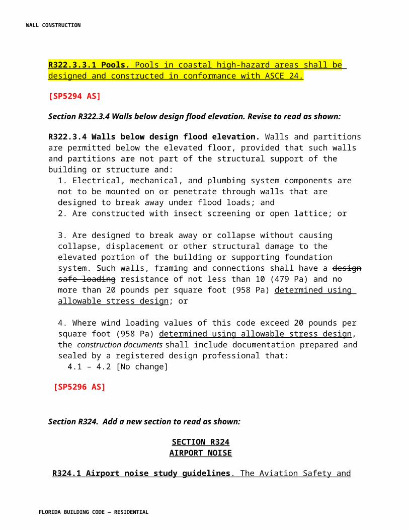
R614.2.2 First-story construction. The concrete, masonry or ICF first-story shall be in accordance with Chapter 6 for the applicable first-story construction method . R614.2.3 Floor systems. The second- and third-story floor system shall be in accordance with Chapter 5. R614.2.4 Second- and third-story construction. The second-and third-story walls, ceilings and roof shall be in accordance with the appropriate sections in Chapters 6, 8, and 9. R614.2.5 Shear wall connections. Second-story shearwalls shall be connected to first-story walls in accordance with Tables 3.2A, 3.2B, 3.2C, A-3.24, 4 3.28 or A-3.2C of the AF&PA Wood Frame Construction Manual for One- and Two-Family Dwellings as applicable.
R614.3 Wood frame gable endwalls above concrete, masonry, or ICF walls. This condition is not permitted unless there is a ceiling diaphragm in accordance with Figures 3.7a and 3.15 of the AF&PA Wood Frame Construction Manual for One- and Two-Family Dwellings.
R614.3.1 Gable construction. Gable construction shall be in accordance with the AF&PA Wood Frame Construction Manual for One- and Two-Family Dwellings. R614.3.2 Wall construction. Concrete, masonry or ICF wall construction shall be in accordance with Chapter 6. R614.3.3 Gable connection. The connection of the wood frame gable endwall to the concrete, masonry or ICF wall shall be in accordance with Figures R614.3(1) and R614.3(2), or Figure R609.4.
[S6017 AS]
Section R615. Add a new major section on Impact-Resistant Coverings to read as shown:
SECTION R615IMPACT-RESISTANT COVERINGS
R615.1 Impact resistant coverings shall be tested at 1.5 times the design pressure (positive or negative) expressed in pounds per square feet as determined by the Florida Building Code, Building Section 1609 for which the specimen is to be tested. The design pressures, as determined from Section 1609 of the Florida Building Code, Building or ASCE 7, are permitted to be multiplied by 0.6.
R615.1.1 Impact resistant coverings shall be labeled in accordance with the provisions of Section R615.
R615.2. Labels. A permanent label shall be provided by the product approval holder on all impact resistant coverings.
R615.2.1 The following information shall be included on the labels on impact resistant coverings:
1. Product approval holder name and address. 2. All applicable methods of approval. Methods of approval include, but, are not limited to Miami-Dade NOA; Florida Building Commission, TDI Product Evaluation; ICC-ES.
WALL CONSTRUCTION
FLORIDA BUILDING CODE — RESIDENTIAL 7.67
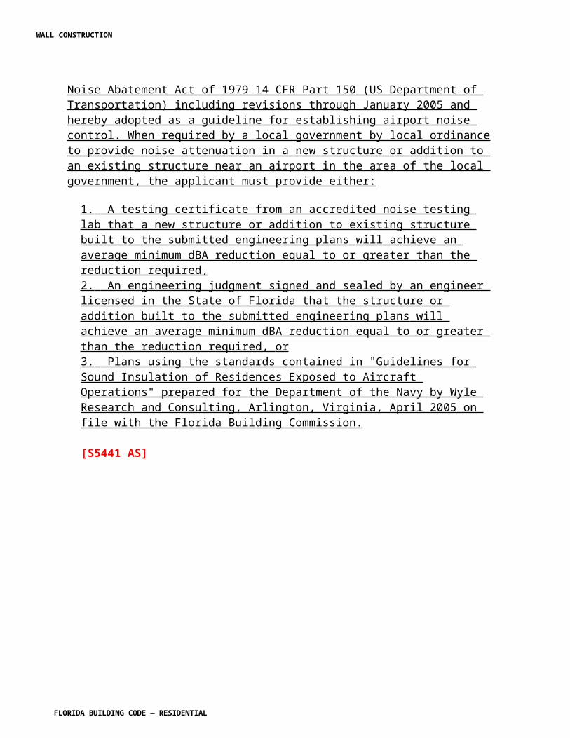
3. The test standard or standards specified at Section R301.2.1.2, including standards referenced within the test standards specified at Section R301.2.1.2 used to demonstrate code compliance.4. For products with a Florida Product Approval Number or a Miami-Dade County Building and Neighborhood Compliance Department Notice of Acceptance Number (NOA), such numbers shall be included on the label.
R615.3 Location of label. The location of the label on the impact resistant covering shall be as follows:
1. Accordions: Bottom of the locking bar or center mate facing the exterior or outside. 2. Rollup: On the bottom of the hood facing the exterior or outside or on the bottom slat facing the exterior or outside.3. Bahama Awning or Colonial Hinged: On the bottom, placed on the back of the shutter. 4. Panels: For metal and plastic panels the label may be embossed or printed spaced not more than every three (3) lineal feet on each panel. The label shall be applied by the holder of the product approval and shall face the exterior or outside.5. Framed products: The label shall be on the side or bottom facing the exterior or outside. 6. Labels on all other products shall face the exterior or outside.
R615.4 Installation. All impact resistant coverings shall be installed in accordance with the manufacturer’s installation instructions and in accordance with the product approval. Installation instructions shall be provided and shall be available to inspection personnel on the job site. Opening protection components, fasteners, and other parts evaluated by an approved product evaluation entity, certification agency, testing laboratory, architect, or engineer and approved by the holder of the product approval may be interchangeable in opening protection assemblies provided that the opening protection component(s) provide equal or greater structural performance and durability as demonstrated by testing in accordance with approved test standards.
[S5723 AS]
WALL CONSTRUCTION
FLORIDA BUILDING CODE — RESIDENTIAL 7.68
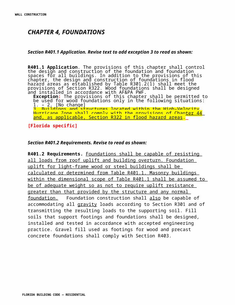
CHAPTER 7
WALL COVERINGS
Section R701.1 Application. Revise to add exception as shown:
R701.1 Application. The provisions of this chapter shall control the design and construction of the interior and exterior wall covering for all buildings.
Exception: Buildings and structures located within the High-Velocity Hurricane Zone shall comply with the provisions of Chapter 44.
Section R703.1.3. Add a new section to read as shown:
R703.1.3 Load resistance. All exterior walls, wall coverings and soffits shall be capable of resisting the design pressures specified in Table R301.2(2) for walls.
[S5704 AS]
Section R703.3. Add a new section to read as shown:
R703.3.3 Attachment. Wood, hardboard and wood structural panel siding shall be attached in accordance with the AF&PA WFCM .
R703.3.4 Minimum thickness. Wood, hardboard and wood structural panel siding shall be of the minimum thickness specified in the AF&PA WFCM .
[S5709 AS]
Section R703.4 Attachments. Revise to read as shown:
R703.4 Attachments. Unless specified otherwise, all wall coverings shall be securely fastened in accordance with Table R703.4 or with other approved aluminum, stainless steel, zinc-coated or other approved corrosion-resistive fasteners. Where wind pressures determined in accordance with Table R301.2(2) the basic wind speed in accordance with Figure R301.2(4)A is 110 miles per hour (49 m/s) or higher, the attachment of wall coverings shall be designed to resist the component and cladding loads specified in Table R301.2(2), adjusted for height and exposure in accordance with Table R301.2(3) do not exceed 30 psf, wall coverings are permitted to be installed in accordance with Table R703.4.
[S5705 AS]
WALL CONSTRUCTION
FLORIDA BUILDING CODE — RESIDENTIAL 7.69
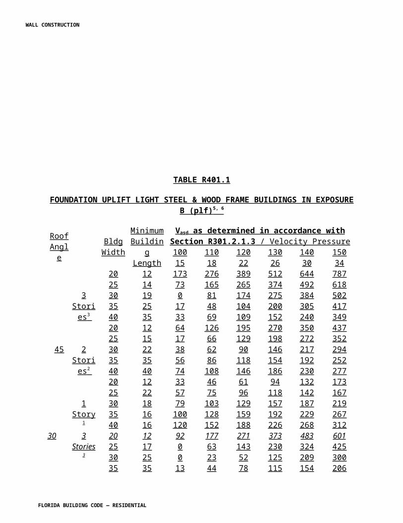
Table R703.4 Weather-Resistant Siding Attachment and Minimum Thickness. Revise to read as shown:
TABLE R703.4WEATHER-RESISTANT SIDING ATTACHMENT AND MINIMUM THICKNESS
Siding Material Nominal Thicknessa
(inches)
Joint Treatment
Water-Resistive Barrier Required
Type of Supports for the Siding Material and Fastenersb,c,d
Wood or Wood Structural Panel Sheathing
Fiberboard Sheathing into Stud
Gypsum Sheathing into Stud
Foam Plastic Sheathing into Stud
Direct to Studs
Number or Spacing of Fasteners
NO change
No changeHardboardk
Panel siding-verticalSee Section R703.3.3
– Yes See Section R703.3.4
Hardboardk
Lap-siding-horizontalSee Section R703.3.3
Note q Yes See Section R703.3.4
Steelh 29 ga. Lap Yes 0.113 nail 1 ¾” Staple-1 ¾”
0.113 nail 2 ¾” Staple-2 1/2 ”
0.113 nail 2 1/2” Staple-2 1/4”
0.113 naily Stapley
Not allowed
Same as stud spacing
Particleboard panels 3/8-1/2 – Yes 6d box nail (2” x 0.099”)
6d box nail (2” x 0.099”)
6d box nail (2” x 0.099”)
box nail 6d box nail (2” x 0.099”)3/8 not allowed
6” panel edges12” inter. Sup.o
5/8 – Yes 6d box nail (2” x 0.099”)
8d box nail (2 1/2” x 0.113”)
8d box nail (2 1/2” x 0.113”)
box nail 6d box nail (2” x 0.099”)
No change
Vinyl sidingm 0.035 Lap Yes See Section R703.3.4 R703.11.
Woodj rustic, drop 3/8 Min Lap Yes Fastener penetration into stud-1” 0.113 nail -2 1/2” Staple-2”
Face nailing up to 6” widths, 1 nail per bearing; 8” widths and over, 2 nails per bearing
Shiplap 19/32 Average
Lap Yes
Bevel 7/16
Butt tip 3/16 Lap Yes
Fiber cement panel sidingr
No change
No change
No change
No change
No change
No change
No change
No change
No change
WALL CONSTRUCTION
FLORIDA BUILDING CODE — RESIDENTIAL 7.70
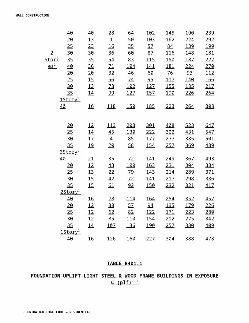
Fiber cement lap sidingr No change
No change
No change
No change
No change
No change
No change
6d corrosion-resistant nailw
Note w
No change to the remaining text of the table.For SI: 1 inch = 25.4 mm.a-b No change c. Reserved. d-i No change.m. Reserved. n. No changeo. Reserved. P – z No change .
[S5706 AS]
Section R703.5.3 Attachment. Revise to read as shown:
R703.5.3 Attachment. Wood shakes and shingles, and attachment and supports shall be capable of resisting the wind pressures determined in accordance with Table R310.2(2).Where wind pressures determined in accordance with Table R301.2(2) do not exceed 30 psf, E each shake or shingle shall be held in place by two hot-dipped zinc-coated, stainless steel, or aluminum nails or staples. The fasteners shall be long enough to penetrate the sheathing or furring strips by a minimum of 1/2 inch (13 mm) and shall not be overdriven. Where pressures determined in accordance with Table R301.2(2) exceed 30 psf, the attachment shall be designed to resist the prescribed wind pressures.
R703.5.3.1 Staple attachment. Reserved Staples shall not be less than 16 gage and shall have a crown width of not less than 7/16 inch (11 mm), and the crown of the staples shall be parallel with the butt of the shake or shingle. In single-course application, the fasteners shall be concealed by the course above and shall be driven approximately 1 inch (25 mm) above the butt line of the succeeding course and 3/4 inch (19 mm) from the edge. In double-course applications, the exposed shake or shingle shall be face-nailed with two casing nails, driven approximately 2 inches (51 mm) above the butt line and 3/4 inch (19 mm) from each edge. In all applications, staples shall be concealed by the course above. With shingles wider than 8 inches (203 mm) two additional nails shall be required and shall be nailed approximately 1 inch (25 mm) apart near the center of the shingle.
[S5710 AS]
Section R703.7 Stone and masonry veneer, general. Revise to read as shown:
R703.7 Stone and masonry veneer, general. Stone and masonry veneer shall be installed in accordance with this chapter, Table R703.4 and Figure R703.7. These veneers installed over a backing of wood or cold-formed steel shall be limited to the first story above-grade plane and shall not exceed 5 inches (127 mm) in thickness. See Section R602.10 for wall bracing requirements for masonry veneer for wood-framed construction and Section R603.9.5 for wall bracing requirements for masonry veneer for cold-formed steel construction. The provisions of this section are limited to areas where the Vasd as determined in accordance with Section R301.2.1.3, is equal to or less than 130 mph.
WALL CONSTRUCTION
FLORIDA BUILDING CODE — RESIDENTIAL 7.71
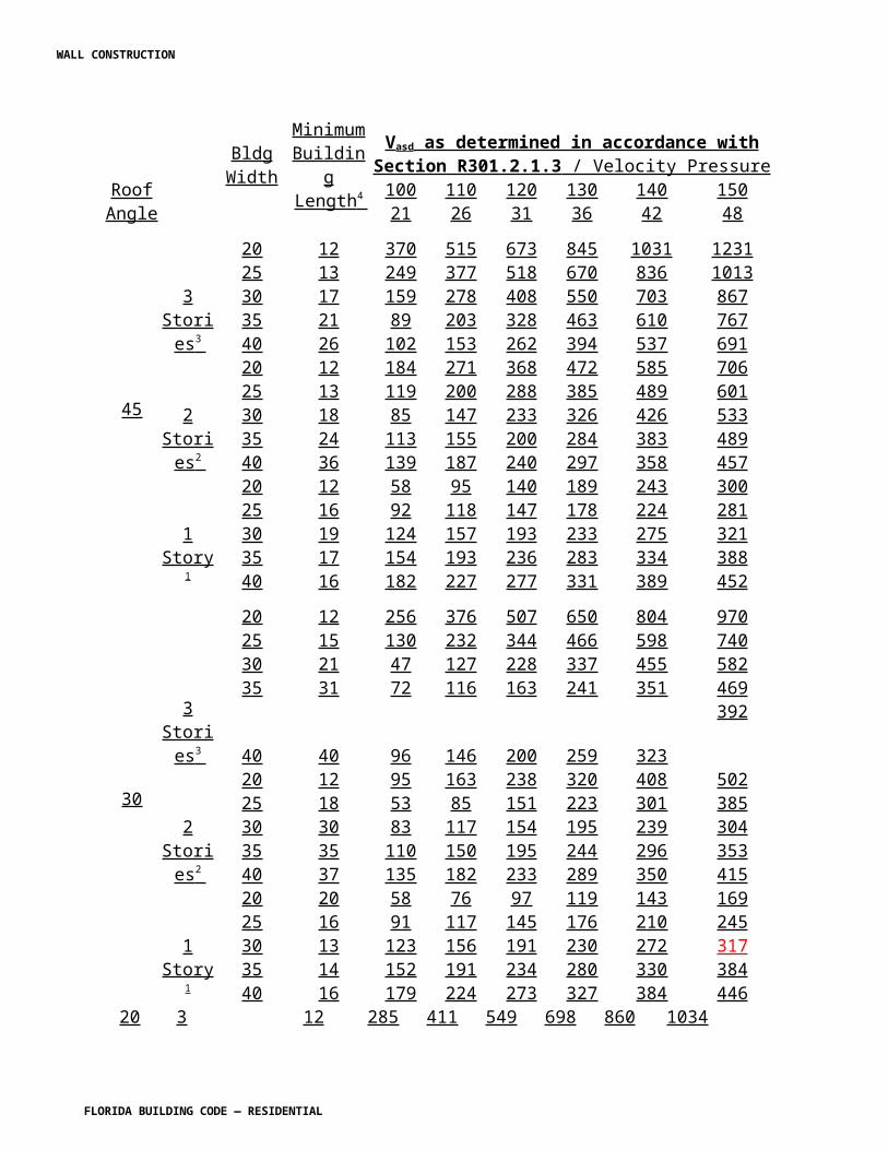
[S5711 AS]
Section R703.7.4.1 Size and spacing. Revise to read as shown:
R703.7.4.1 Size and spacing. Veneer ties, if strand wire, shall not be less in thickness than No. 9 U.S. gage [(0.148 inch) (4 mm)] wire and shall have a hook embedded in the mortar joint, or if sheet metal, shall be not less than No. 22 U.S. gage by [(0.0299 inch) (0.76 mm)] 7/8 inch (22 mm) corrugated. Each tie shall support not more than 2.67 square feet (0.25 m2) of wall area and shall be spaced not more than 32 inches (813 mm) on center horizontally and 24 inches (635 mm) on center vertically.
Exception: 1. In Seismic Design Category D0, D1 or D2 or townhouses in Seismic Design Category C or in wind areas of more than 30 pounds per square foot pressure (1.44 kPa), each tie shall support not more than 2 square feet (0.2 m2) of wall area.2. Where the V asd as determined in accordance with Section R301.2.1.3 exceeds 110 mph (176.99 km/h) or is less than or equal to 130 mph (208 km/h), each tie shall support not more than 1.8 square feet (0.167 m 2 ) of wall area and anchors shall be spaced at a maximum 18 inches (457 mm) horizontally and vertically.
[S5711 AS]
Section R703.8 Flashing. Revise to read as shown:
R703.8 Flashing. Approved corrosion-resistant flashing shall be applied shingle-fashion in a manner to prevent entry of water into the wall cavity or penetration of water to the building structural framing components. Self-adhered membranes used as flashing shall comply with AAMA 711. All exterior fenestration products shall be sealed at the juncture with the building wall with a sealant complying with AAMA 800 or ASTM C 920 Class 25 Grade NS or greater for proper joint expansion and contraction, ASTM C 1281 , AAMA 812 , or other approved standard as appropriate for the type of sealant. The flashing shall extend to the surface of the exterior wall finish. Approved corrosion-resistant flashings shall be installed at all of the following locations:
1. Exterior window and door openings. Flashing at exterior window and door openings shall extend to the surface of the exterior wall finish or to the water-resistive barrier for subsequent drainage. Flashing at exterior window and door openings shall be installed in accordance with one or more of the following:
1.1. The fenestration manufacturer’s installation and flashing instructions, or for applications not addressed in the fenestration manufacturer’s instructions, in accordance with the flashing manufacturer’s instructions. Where flashing instructions or details are not
WALL CONSTRUCTION
FLORIDA BUILDING CODE — RESIDENTIAL 7.72
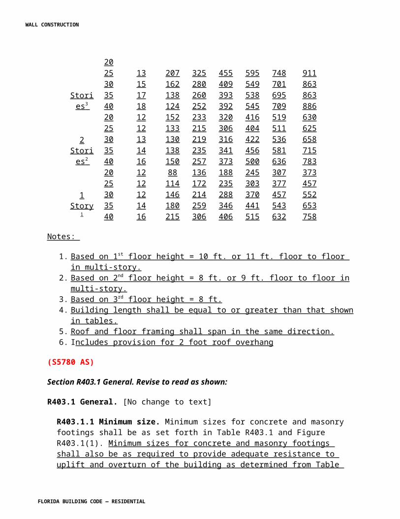
provided, pan flashing shall be installed at the sill of exterior window and door openings. Pan flashing shall be sealed or sloped in such a manner as to direct water to the surface of the exterior wall finish or to the water-resistive barrier for subsequent drainage. Openings using pan flashing shall also incorporate flashing or protection at the head and sides.1.2. In accordance with the flashing design or method of a registered design professional.1.3. In accordance with other approved methods.1.4. In accordance with FMA/AAMA 100, FMA/AAMA 200, FMA/WDMA 250, or FMA/AAMA/WDMA 300.
2. At the intersection of chimneys or other masonry construction with frame or stucco walls, with projecting lips on both sides under stucco copings.
3. Under and at the ends of masonry, wood or metal copings and sills.
4. Continuously above all projecting wood trim.
5. Where exterior porches, decks or stairs attach to a wall or floor assembly of wood-frame construction.
6. At wall and roof intersections.
7. At built-in gutters.
[S5750-R1 AM]
Change R703.9 as shown:
R703.9 Exterior insulation and finish system (EIFS)/EIFS with drainage. Exterior Insulation and Finish System (EIFS) shall be designed or tested to meet the wind pressures specified in Table R301.2(2) and shall comply with this chapter and Sections R703.9.1 and R703.9.3. EIFS with drainage shall comply with this chapter and Sections R703.9.2, R703.9.3 and R703.9.4.
Section R703.11.2 Foam plastic sheathing. Revise to read as shown:
R703.11.2 Foam plastic sheathing. Vinyl siding used with foam plastic sheathing shall be installed in accordance with Section R703.11.2.1, or R703.11.2.2, or R703.11.2.3.
Exception: Where the foam plastic sheathing is applied directly over wood structural panels, 1fiberboard, gypsum sheathing or other approved backing capable of independently resisting the design wind pressure, the vinyl siding shall be installed in accordance with Section R703.11.1.
WALL CONSTRUCTION
FLORIDA BUILDING CODE — RESIDENTIAL 7.73
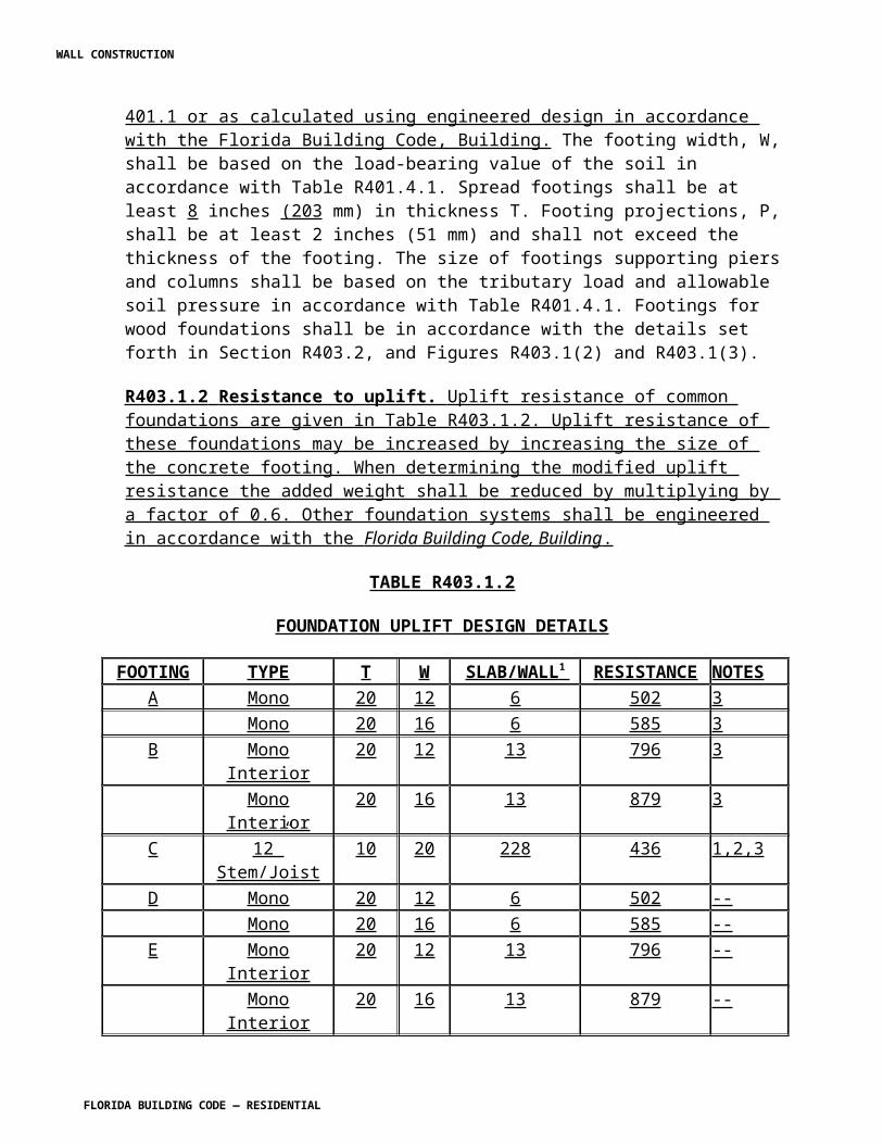
R703.11.2.1 Reserved. Basic wind speed not exceeding 90 miles per hour and Exposure Category B. Where the basic wind speed does not exceed 90 miles per hour (40 m/s), the Exposure Category is B and gypsum wall board or equivalent is installed on the side of the wall opposite the foam plastic sheathing, the minimum siding fastener penetration into wood framing shall be 11/4 inches (32 mm) using minimum 0.120-inch diameter nail (shank) with a minimum 0.313-inch diameter head, 16 inches on center. The foam plastic sheathing shall be minimum 1/2-inch-thick (12.7 mm) (nominal) extruded polystyrene per ASTM C 578, 1/2-inch-thick (12.7 mm) (nominal) polyisocyanurate per ASTM C 1289, or 1- inch-thick (25 mm) (nominal) expanded polystyrene per ASTM C 578.
R703.11.2.2 Design wind pressure rating. Basic wind speed exceeding 90 miles per hour or Exposure Categories C and D. Where the basic wind speed exceeds 90 miles per hour (40 m/s) or the Exposure Category is C or D, or all conditions of Section R703.11.2.1 are not met, the adjusted design pressure rating for the assembly shall meet or exceed the loads listed in Tables R301.2(2) adjusted for height and exposure using Table R301.2(3). Where the Vult
wind speed does not exceed 140 mph, Tthe design wind pressure rating of the vinyl siding for installation over solid sheathing as provided in the vinyl siding manufacturer’s product specifications shall be adjusted for the following wall assembly conditions:
1. Ultimate wind speeds, Vult, greater than 115 mph and less than 130 mph: 1 a. For wall assemblies with foam plastic sheathing on the exterior side and gypsum wall board or equivalent on the interior side of the wall, the vinyl siding’s design wind pressure rating shall be multiplied by 0.39.2 b. For wall assemblies with foam plastic sheathing on the exterior side and no gypsum wall board or equivalent on the interior side of wall, the vinyl siding’s design wind pressure rating shall be multiplied by 0.27.
The adjusted design pressure rating for the assembly shall meet or exceed the loads listed in Tables R301.2(2) adjusted for height and exposure using Table R301.2(3).
2. Ultimate wind speeds, Vult, greater than 130 mph and less than 140 mph:a. The vinyl siding’s design wind pressure rating shall be multiplied by 0.27.
The adjusted design pressure rating for the assembly shall meet or exceed the loads listed in Tables R301.2(2) adjusted for height and exposure using Table R301.2(3).
R703.11.2.3 Manufacturer specification. [No change to text]
[S5947 AS]
WALL CONSTRUCTION
FLORIDA BUILDING CODE — RESIDENTIAL 7.74
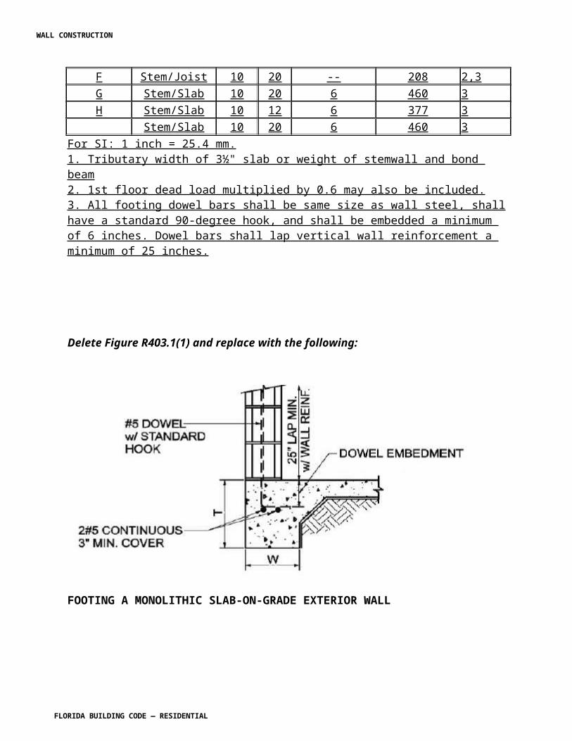
CHAPTER 8ROOF-CEILING CONSTRUCTION
Add an exception to R801.1 as shown:
R801.1 Application. The provisions of this chapter shall control the design and construction of the roof-ceiling system for all buildings (see Section R301.2.1.1).
Exception: Buildings and structures located within the High-Velocity Hurricane Zone shall comply with the provisions of Chapter 44.
Section R802.1 Identification. Revise to read as shown:
R802.1 General Requirements. Roof and ceiling framing of wood construction shall be designed and constructed in accordance with the provisions of this Section.
R802.1.1 [IRC802.1] Identification. [No change to text]
R802.1.1.1 [IRC802.1.1] Blocking. [No change to text]
R802.1.7 [IRC802.10] Wood trusses.
R802.1.7.1 [IRC802.10.1] Truss design drawings. Truss design drawings, prepared in conformance with Section R802.1.7.1, R802.10.1 shall be provided to the building official and approved prior to installation. Truss design drawings shall include, at a minimum, the information specified below. Truss design drawing shall be provided with the shipment of trusses delivered to the jobsite.
1. Ultimate design wind speed, Vult, and exposure category.2. Slope or depth, span and spacing.3. Location of all joints.4. Required bearing widths.5. Design loads as applicable.
5.1 Top chord live load (as determined from Section R301.6). 5.2 Top chord dead load. 5.3 Bottom chord live load. 5.4 Bottom chord dead load. 5.5 Concentrated loads and their points of application. 5.6 Controlling wind and earthquake loads.
6. Adjustments to lumber and joint connector design values for conditions of use.7. Each reaction force and direction.8. Joint connector type and description (e.g., size, thickness or gauge) and the dimensioned location of each joint connector except where symmetrically located relative to the joint interface.9. Lumber size, species and grade for each member.
WALL CONSTRUCTION
FLORIDA BUILDING CODE — RESIDENTIAL 7.75
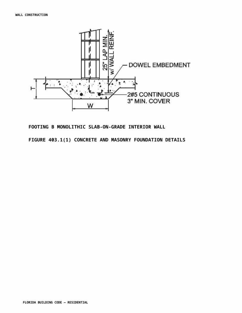
10. Connection requirements for: 10.1 Truss to truss girder. 10.2 Truss ply to ply. 10.3 Field splices.11. Calculated deflection ratio and/or maximum description for live and total load.12. Maximum axial compression forces in the truss members to enable the building designer to design the size, connections and anchorage of the permanent continuous lateral bracing. Forces shall be shown on the truss design drawing or on supplemental documents.13. Required permanent truss member bracing location.
R802.1.7.2 R802.10.2 Design. Wood trusses shall be designed in accordance with accepted engineering practice. The design and manufacture of metal-plate-connected wood trusses shall comply with ANSI/TPI 1. The truss design drawings shall be prepared by a registered professional where required by Florida Statutes the statutes of the jurisdiction in which the project is to be constructed in accordance with Section R106.1.
R802.1.7.2.1 R802.10.2. Applicability limits. Reserved.
R802.1.7.3 R802.10.3 Bracing. [No other change to IRC text]
R802.1.7.4 R802.10.4 Alterations to trusses. [No other change to IRC text]
R802.1.7.5 R802.10.5 Truss to wall connection. Trusses shall be connected to wall plates by the use of approved connectors having a resistance to design uplift, lateral and shear forces. Trusses shall be installed in accordance with the manufacturer’s design and specifications. For roof assemblies subject to wind uplift pressures of 20 pounds per square foot (0.958 kN/m2) or greater, as established in Table R301.2(2), adjusted for height and exposure per Table R301.2(3), see Section R802.2.9.
R802.1.8 R802.7 Cutting and notching. [No other change to IRC text]
R802.1.8.1 R802.7.1 Sawn lumber. [No other change to IRC text]
R802.1.8.1.1 R802.7.1.1 Cantilevered portions of rafters. [No other change to IRC text]
R802.1.8.1.2 R802.7.1.2 Ceiling joist taper cut. [No other change to IRC text]
R802.1.8.2 R802.7.2Engineered wood products. [No other change to IRC text].
R802.2 Design and construction. Roof-ceilings of light-frame wood construction shall be designed and constructed in accordance with the provisions of Section R301.2.1.1 and Section R802.1.
WALL CONSTRUCTION
FLORIDA BUILDING CODE — RESIDENTIAL 7.76
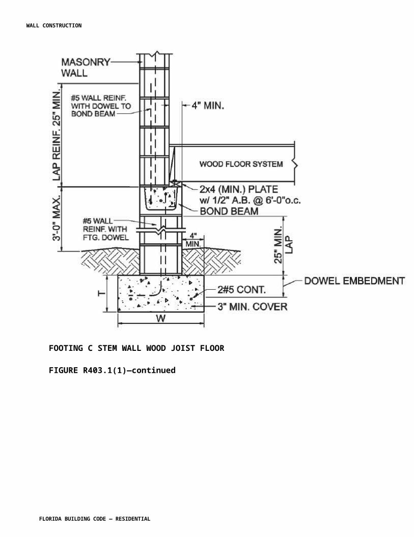
Exceptions:
1. For rafter connections to the top plate, straps and/or clips shall extend such that the top nail is within 1 inch of the top of the rafter with one or more nails installed on the opposite side of the rafter.
2. Roof sheathing shall be at a minimum attached in accordance with Section R803.2.3.
The framing details required in Section R802 apply to roofs having a minimum slope of three units vertical in 12 units horizontal (25-percent slope) or greater. Roof-ceilings shall be designed and constructed in accordance with the provisions of this chapter and Figures R606.11(1), R606.11(2) and R606.11(3) or in accordance with AFPA/NDS. Components of roof-ceilings shall be fastened in accordance with Table R602.3(1).
Delete the remainder of Section R802 and show as "Reserved."
(S5989 AS)
Section R803.2.3 Installation. Change to read as shown:
R803.2.3 Installation. Wood structural panel used as roof sheathing shall be installed with joints staggered in accordance with Section R802.3.1 or not staggered in accordance with Table R602.3(1), or APA E30 for wood roof framing or in accordance with AISI 230 with Table R804.3 for steel roof framing.
R803.2.3.1 Sheathing fastenings. Wood structural panel sheathing shall be fastened to roof framing with 8d annular ring-shank nails at 6 inches on center at edges and 6 inches on center at intermediate framing. Ring-shank nails shall have the following minimum dimensions:
1. 0.113 inch nominal root shank diameter 2. Ring diameter of 0.010 0.012 over shank diameter 3. 16 to 20 rings per inch4. 0.280 inch full round head diameter5. 2-3/8 inch nail length
Where roof framing with a specific gravity, 0.42 = G < 0.49 is used, spacing of ring-shank fasteners shall be 4 inches on center in nailing zone 3 in accordance with Figure R803.2.3.1 where Vult is 165 160 mph or greater.
Exceptions:
1. Where roof framing with a specific gravity, 0.42 = G < 0.49 is used, spacing of ring-shank fasteners shall be permitted at 12 inches on center at intermediate framing in nailing zone 1 for any Vult and in nailing zone 2 for Vult less than or equal to 140 mph in
WALL CONSTRUCTION
FLORIDA BUILDING CODE — RESIDENTIAL 7.77
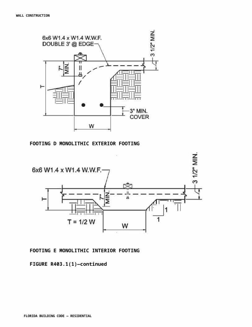
accordance with Figure R803.2.3.1 2304.7.2.1.1 .
2. Where roof framing with a specific gravity, G = 0.49 is used, spacing of ring-shank fasteners shall be permitted at 12 inches on center at intermediate framing in nailing zone 1 for any Vult and in nailing zone 2 for Vult less than or equal to 150 mph in accordance with Figure R803.2.3.1 2304.7.2.1.1 .
3. Where roof framing with a specific gravity, G = 0.49 is used, 8d common or 8d hot dipped galvanized box nails at 6 inches on center at edges and 6 inches on center at intermediate framing shall be permitted for Vult less than or equal to 130 mph in accordance with Figure R803.2.3.1 2304.7.2.1.1 .
4. Where roof diaphragm requirements necessitate a closer fastener spacing.
FIGURE R803.2.3.1 ROOF SHEATHING NAILING ZONES [S5673 AM R1]
WALL CONSTRUCTION
FLORIDA BUILDING CODE — RESIDENTIAL 7.78
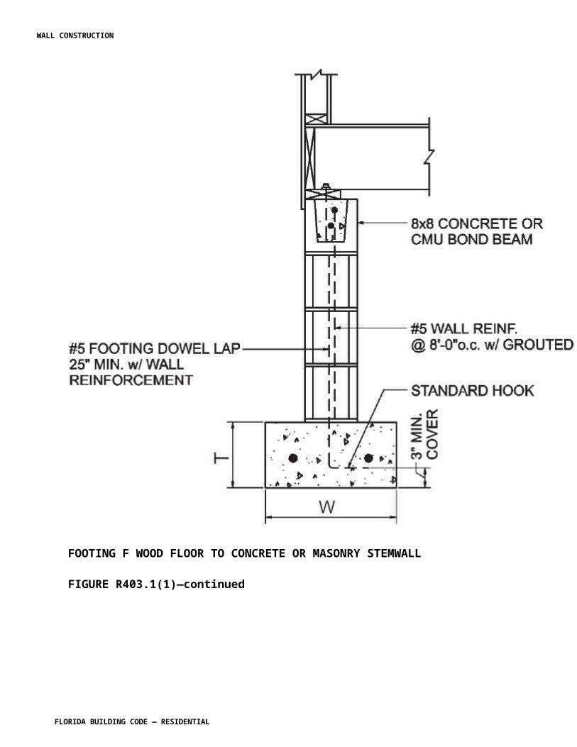
Section R804 Steel Roof Framing. Revise to read as shown:
SECTION R804STEEL ROOF FRAMING
RESERVED[S6003 AS]
WALL CONSTRUCTION
FLORIDA BUILDING CODE — RESIDENTIAL 7.79
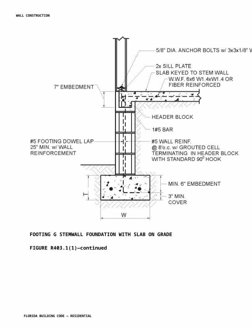
CHAPTER 9 ROOF ASSEMBLIES
R901.1 Scope. Add exception as shown:
R901.1 Scope. The provisions of this chapter shall govern the design, materials, construction and quality of roof assemblies.
Exception: Buildings and structures located within the High-Velocity Hurricane Zone shall comply with the provisions of Chapter 44.
SECTION 903WEATHER PROTECTION
Section R903.2.1 Locations. Change to read as shown:
R903.2.1 Locations. Flashings shall be installed at wall and roof intersections, wherever there is a change in roof slope or direction and around roof openings. A flashing shall be installed to divert the water away from where the eave of a sloped roof intersects a vertical sidewall. Where flashing is of metal, the metal shall be corrosion resistant with a thickness of not less than 0.019 inch (0.5 mm) (No. 26 galvanized sheet) provided in Table R903.2.1.
Exception: Flashing is not required at hip and ridge junctions .
TABLE R903.2.1METAL FLASHING MATERIAL
MATERIAL
GAGE MINIMUMTHICKNESS
(INCHES) GAGE
WEIGHT(lbs per sq
ft)Copper 0.024 1 (16 oz)Aluminum 0.024Stainless steel 28
Galvanizedsteel 0.0179 26
(zinc coated G90)
26(zinc coated
G90)Aluminumzinc coatedsteel
0.017926
(AZ50 alumzinc)
26(AZ50
alum zinc)Zinc alloy 0.027Lead 2.5 (40 oz)Painted terne 1.25 (20 oz)
(R5473 AS)
WALL CONSTRUCTION
FLORIDA BUILDING CODE — RESIDENTIAL 7.80
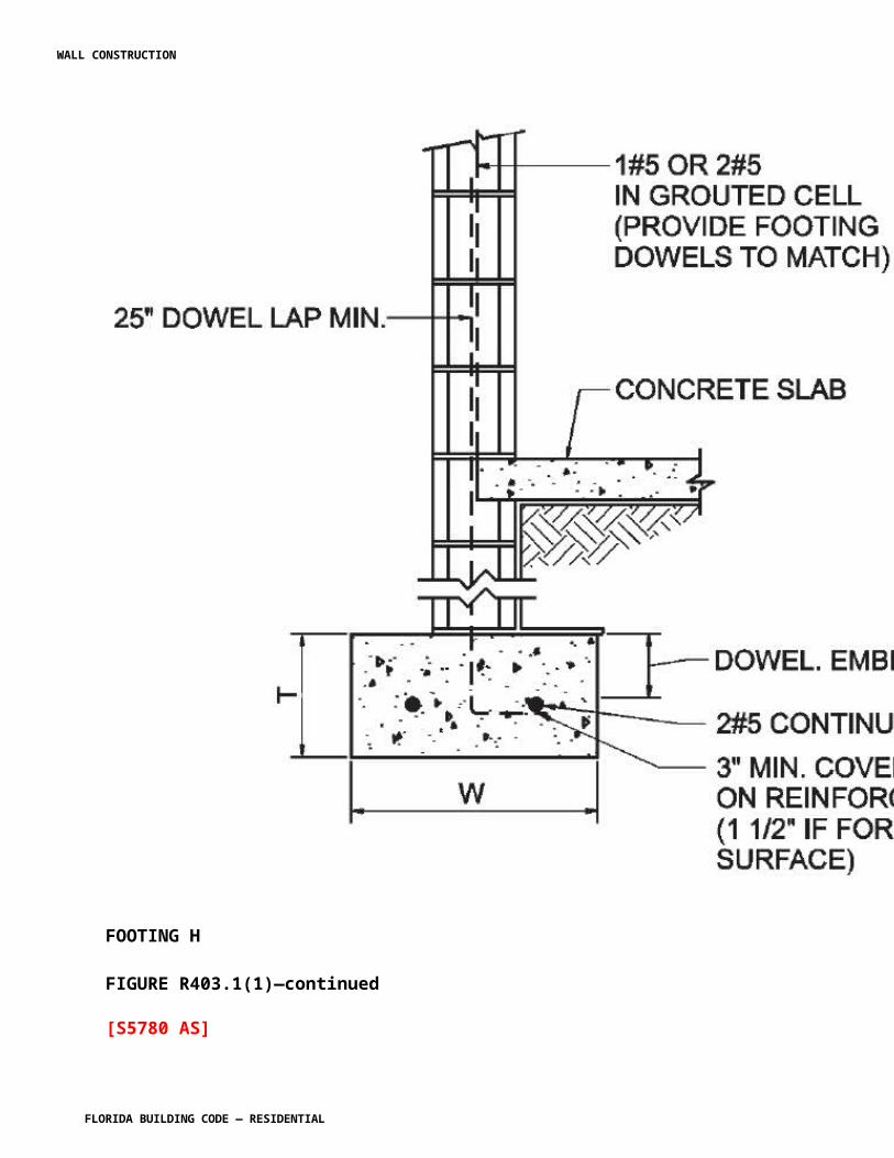
Section R903.2.3. Add a section to read as shown:
R903.2.3 Membrane flashings. All membrane flashing shall be installed according to the roof assembly manufacturer’s published literature.
(R5475 AS)
Section R903.4 Roof drainage. Change to read as shown:
R903.4 Roof drainage. Unless roofs are sloped to drain over roof edges, roof drains shall be installed at each low point of the roof. Where required for roof drainage, scuppers shall be placed level with the roof surface in a wall or parapet. The scupper shall be located as determined by the roof slope and contributing roof area.
(R5478 AS)
Section R903.4.1 Secondary (emergency overflow) drains or scuppers. Change to read as follows:
R903.4.1 Secondary (emergency overflow) drains or scuppers. Overflow drains and scuppers. When other means of drainage of overflow water is not provided, overflow scuppers shall be placed in walls or parapets not less than 2 inches (51 mm) nor more than 4 inches (102 mm) above the finished roof covering and shall be located as close as practical to required vertical leaders or downspouts or wall and parapet scuppers. An overflow scupper shall be sized in accordance with the Florida Building Code, Plumbing.
Where roof drains are required, secondary emergency overflow roof drains or scuppers shall be provided where the roof perimeter construction extends above the roof in such a manner that water will be entrapped if the primary drains allow buildup for any reason. Overflow drains having the same size as the roof drains shall be installed with the inlet flow line located 2 inches (51 mm) above the low point of the roof, or overflow scuppers having three times the size of the roof drains and having a minimum opening height of 4 inches (102 mm) shall be installed in the adjacent parapet walls with the inlet flow located 2 inches (51 mm) above the low point of the roof served. The installation and sizing of overflow drains, leaders and conductors shall comply with Sections 1106 and 1108 as applicable of the International Plumbing Code.
Overflow drains shall discharge to an approved location and shall not be connected to roof drain lines.
(R5476 AS)
Section R903.4.2. Add a new section to read as follows:
R903.4.2 One and two family dwellings, and private garages. When gutters and leaders are placed on the outside of buildings, the gutters and leaders shall be constructed of metal or
WALL CONSTRUCTION
FLORIDA BUILDING CODE — RESIDENTIAL 7.81
approved plastic for outdoor exposure with lapped, soldered or caulked joints and shall be securely fastened to the building with a corrosion resistant fastening device of similar or compatible material to the gutters and downspouts.
(R5477 AS)
SECTION R904MATERIALS
Section R904. Change to read as follows:
R904.1 Scope. The requirements set forth in this section shall apply to the application of roof covering materials specified herein. Roof assemblies shall be applied in accordance with this chapter and the manufacturer’s installation instructions. Installation of roof assemblies shall comply with the applicable provisions of Section R905.
R904.2 Compatibility of materials. Roof assemblies shall be of materials that are compatible with each other and with the building or structure to which the materials are applied.
R904.3 Material specifications and physical characteristics. Roof covering materials shall conform to the applicable standards listed in this chapter. In the absence of applicable standards or where materials are of questionable suitability, testing by an approved testing agency shall be required by the building official to determine the character, quality and limitations of application of the materials.
R904.4 Fasteners.
R904.4.1 Nails. Nails shall be corrosion resistant nails conforming to ASTM F 1667. The corrosion resistance shall meet ASTM A 641, Class I or an equal corrosion resistance by coating, electro galvanization, mechanical galvanization, hot dipped galvanization, stainless steel, nonferrous metal and alloys or other suitable corrosion-resistant material. Metal or plastic cap nails shall have a head diameter of not less than 1 inch (25.4 mm) with a thickness of at least 32-gauge sheet metal, Metal tin-tabs shall be not less than 1 5 / 8 inches (41 mm) and not more than 2 inches (51 mm) in diameter and of not less than 32 gage (0.010 inch) sheet metal in compliance with the corrosion resistance requirements.
R904.4.2 Screws. Wood screws shall conform to ANSI/ASME B 18.6.1. Screws shall be corrosion resistant by coating, galvanization, stainless steel, nonferrous metal or other suitable corrosion resistant material. The corrosion resistance shall be demonstrated through one of the following methods:
1. Corrosion resistance equivalent to ASTM A 641, Class 1; 2. Corrosion resistance in accordance with TAS 114, Appendix E; 3. Corrosion resistant coating exhibiting not more than 5 percent red rust after 1000 hours exposure in accordance with ASTM B 117.
WALL CONSTRUCTION
FLORIDA BUILDING CODE — RESIDENTIAL 7.82
R904.4.3 Clips. Clips shall be corrosion resistant clips. The corrosion resistance shall meet 0.90 ounce per square foot (0.458 kg/m 2 ) measured according ASTM A 90/A 90M, TAS 114 Appendix E or an equal corrosion resistance coating, electro galvanization, mechanical galvanization, hot dipped galvanization, stainless steel, nonferrous metals and alloys or other suitable corrosion resistant material. Stainless steel clips shall conform to ASTM A167, Type 304.
R904.4 R904.5 Product identification. Roof covering materials shall be delivered in packages bearing the manufacturer’s identifying marks and approved testing agency labels when required. Bulk shipments of materials shall be accompanied by the same information issued in the form of a certificate or on a bill of lading by the manufacturer.
(R5300 AS)
SECTION R905REQUIREMENTS FOR ROOF COVERINGS
Section R905.2.2 Slope. Change to read as shown:
R905.2.2 Slope. Asphalt shingles shall be used only on roof slopes of two units vertical in 12 units horizontal (2:12) or greater. For roof slopes from two units vertical in 12 units horizontal (2:12) up to and less than four units vertical in 12 units horizontal (4:12), double underlayment application is required in accordance with Section R905.2.7.
(R5484 AS)
Section R905.2.3 Underlayment. Change to read as shown:
R905.2.3 Underlayment. Unless otherwise noted, required underlayment shall conform to with ASTM D 226 Type I or Type II, ASTM D 4869, Type I II or Type IV, or ASTM D 6757.
Self-adhering polymer modified bitumen sheet shall comply with ASTM D 1970.
(R5485 AS)
R905.2.4.1 Wind resistance of asphalt shingles. Change to read as shown:
R905.2.4.1 Wind resistance of asphalt shingles. Asphalt shingles shall be tested in accordance with ASTM D 7158. Asphalt shingles shall meet the classification requirements of Table R905.2.4.1(1) for the appropriate maximum basic wind speed. Asphalt shingle packaging shall bear a label to indicate compliance with ASTM D 7158 and the required classification in Table R905.2.4.1(1) installed in accordance with Section R905.2.6. and R905.2.6.1.
WALL CONSTRUCTION
FLORIDA BUILDING CODE — RESIDENTIAL 7.83
Exception: Asphalt shingles not included in the scope of ASTM D 7158 shall be tested and labeled to indicate compliance with ASTM D 3161 and the required classification in Table R905.2.4.1(2).
TABLE R905.2.4.1(1)CLASSIFICATION OF ASPHALT ROOF SHINGLES PER ASTM D 7158
Reserved.
MAXIMUM BASIC WIND SPEED FROM FIGURE 301.2(4)A (mph) CLASSIFICATION REQUIREMENT
85 D, G or H90 D, G or H100 G or H110 G or H120 G or H130 H140 H150 H
For SI: 1 mile per hour = 0.447 m/s.
TABLE R905.2.4.1(2)CLASSIFICATION OF ASPHALT SHINGLES PER ASTM D 3161
Reserved.
MAXIMUM BASIC WIND SPEED FROM FIGURE 301.2(4)A (mph) CLASSIFICATION REQUIREMENT
85 A, D or F90 A, D or F100 A, D or F110 F120 F130 F140 F150 F
For SI: 1 mile per hour = 0.447 m/s.
(R5486 AS)
WALL CONSTRUCTION
FLORIDA BUILDING CODE — RESIDENTIAL 7.84
Section R905.2.6.1. Add a new section to read as follows:
R905.2.6.1 Wind Resistance of Asphalt Shingles. Asphalt Shingles shall be classified in accordance with ASTM D 3161, TAS 107 or ASTM D 7158 to resist the basic wind speed per Figure R301.2(4). Shingles classified as ASTM D 3161 Class D or classified as ASTM D 7158 Class G are acceptable for use in the 100-mph wind zone. Shingles classified as ASTM D 3161 Class F, TAS107 or ASTM D 7158 Class H are acceptable for use in all wind zones. Asphalt shingle wrappers shall indicate compliance with one of the required classifications as shown in Table R905.2.6.1.
TABLE R905.2.6.1WIND RESISTANCE OF ASPHALT SHINGLES
Classification of Asphalt Shingles
Maximum Basic Wind Speed, V ult,
From Figure R301.2(4)
Vasd as determined in
accordance with Section
R301.2.1.3 ASTM D 7158 ASTM D 3161110 85 D, G or H A, D or F 116 90 D, G or H A, D or F 129 100 G or H A, D or F 142 110 G or H F155 120 G or H F168 130 H F181 140 H F194 150 H F
(R5487 AM R2)
Section R905.2.7 Underlayment application. Change to read as shown:
R905.2.7 Underlayment application. Underlayment shall be installed using one of the following methods:For roof slopes from two units vertical in 12 units horizontal (17-percent slope), up to four units vertical in 12 units horizontal (33-percent slope), underlayment shall be two layers applied in the following manner. Apply a 19-inch (483 mm) strip of underlayment felt parallel to with and starting at the eaves, fastened sufficiently to hold in place. Starting at the eave, apply 36-inch-wide (914 mm) sheets of underlayment, overlapping successive sheets 19 inches (483 mm), and fastened sufficiently to hold in place. Distortions in the underlayment
WALL CONSTRUCTION
FLORIDA BUILDING CODE — RESIDENTIAL 7.85
shall not interfere with the ability of the shingles to seal. End laps shall be offset by 6 feet (1829 mm). For roof slopes of four units vertical in 12 units horizontal (33-percent slope) or greater, underlayment shall be one layer applied in the following manner. Underlayment shall be applied shingle fashion, parallel to and starting from the eave and lapped 2 inches (51 mm) fastened sufficiently to hold in place. Distortions in the underlayment shall not interfere with the ability of the shingles to seal. End laps shall be offset by 6 feet (1829 mm).
1. For roof slopes from two units vertical in 12 units horizontal (17-percent slope), and less than four units vertical in 12 units horizontal (33-percent slope). Underlayment shall comply with ASTM D 226, Type I or Type II or ASTM D 4869, Type II or Type IV or ASTM D 6757 and shall be two layers applied in the following manner. Apply a 19-inch (483 mm) strip of underlayment felt parallel to and starting at the eaves, fastened sufficiently to hold in place. Starting at the eave, apply 36-inch-wide (914 mm) sheets of underlayment, overlapping successive sheets 19 inches (483 mm), and fastened with 1 inch (25 mm) round plastic cap, metal cap nails or nails and tin-tabs attached to a nailable deck with one row in the field of the sheet with a maximum fastener spacing of 12 in. o.c. (305 mm), and one row at the overlaps fastened 6 in. o.c. (152 mm). Synthetic underlayment shall be fastened in accordance with this section and the manufacturer’s recommendations. 2. For roof slopes of four units vertical in 12 units horizontal (33-percent slope) or greater. Underlayment shall comply with ASTM D 226, Type II or ASTM D 4869, Type IV or ASTM D 6757 and shall be one layer applied in the following manner. Underlayment shall be applied shingle fashion, parallel to and starting from the eave and lapped 2 inches (51 mm), fastened with 1 inch (25 mm) round plastic cap, metal cap nails or nails and tin-tabs attached to a nailable deck with two staggered rows in the field of the sheet with a maximum fastener spacing of 12 in. o.c. (305 mm), and one row at the overlaps fastened 6 in. o.c. (152 mm). Synthetic underlayment shall be fastened in accordance with this section and the manufacturer’s recommendations End laps shall be offset by 6 feet (1829 mm). 3. As an alternative, the entire roof deck shall be covered with an approved self- adhering polymer modified bitumen sheet meeting ASTM D 1970 or an approved self- adhering synthetic underlayment installed in accordance with the manufacturer’s installation instructions.
(R5555 AS)
R905.2.7.1 Ice barrier. Reserved. In areas where there has been a history of ice forming along the eaves causing a backup of water as designated in Table R301.2(1), an ice barrier that consists of a least two layers of underlayment cemented together or of a self-adhering polymer modified bitumen sheet, shall be used in lieu of normal underlayment and extend from the lowest edges of all roof surfaces to a point at least 24 inches (610 mm) inside the exterior wall line of the building. Exception: Detached accessory structures that contain no conditioned floor area.
WALL CONSTRUCTION
FLORIDA BUILDING CODE — RESIDENTIAL 7.86
(R5488 AS)
R905.2.7.2 Underlayment and high winds. Reserved.Underlayment applied in areas subject to high winds [above 110 mph (49 m/s) in accordance with Figure R301.2(4)A] shall be applied with corrosion-resistant fasteners in accordance with manufacturer’s installation instructions. Fasteners are to be applied along the overlap not farther apart than 36 inches (914 mm) on center. Underlayment installed where the basic wind speed equals or exceeds 120 mph (54 m/s) shall comply with ASTM D 226 Type II, ASTM D 4869 Type IV, or ASTM D 6757. The underlayment shall be attached in a grid pattern of 12 inches (305 mm) between side laps with a 6-inch (152 mm) spacing at the side laps. Underlayment shall be applied in accordance with Section R905.2.7 except all laps shall be a minimum of 4 inches (102 mm). Underlayment shall be attached using metal or plastic cap nails with a head diameter of not less than 1 inch (25.4 mm) with a thickness of at least 32-gauge sheet metal. The cap-nail shank shall be a minimum of 12 gauge (0.105 inches) with a length to penetrate through the roof sheathing or a minimum of 3/4 inch (19 mm) into the roof sheathing. Exception: As an alternative, adhered underlayment complying with ASTM D 1970 shall be permitted.
(R5489 AS)
Section R905.2.8 Flashing. Change to read as shown:
R905.2.8.1 Base and cap counter flashing. Base and cap counter flashing shall be installed in accordance with manufacturer’s installation instructions. Base flashing shall be of either corrosion-resistant metal of minimum nominal 0.019-inch (0.5 mm) thickness or mineral surface roll roofing weighing a minimum of 77 pounds per 100 square feet (4 kg/m2). Cap flashing shall be corrosion-resistant metal of minimum nominal 0.019-inch (0.5 mm) thickness as follows:
1. In accordance with manufacturer’s installation instructions, or
2. A continuous metal minimum 4 inch by 4 inch "L” flashing shall be set in approved flashing cement and set flush to base of wall and over the underlayment. Both horizontal and vertical metal flanges shall be fastened 6 inches (152 mm) on center with approved fasteners. All laps shall be a minimum of 4 inches (102 mm) fully sealed in approved flashing cement. Flashing shall start at the lower portion of roof to ensure water-shedding capabilities of all metal laps. The entire edge of the horizontal flange shall be sealed covering all nail penetrations with approved flashing cement and membrane. Shingles shall overlap the horizontal flange and shall be set in approved flashing cement.
Base flashing shall be of either corrosion-resistant metal provided in Section R905.2.8.1 or mineral surface roll roofing weighing a minimum of 77 pounds per 100 square feet (3.76 kg/m 2 ). Counter flashing shall be corrosion-resistant metal with a minimum thickness provided in Table R903.2.1.
WALL CONSTRUCTION
FLORIDA BUILDING CODE — RESIDENTIAL 7.87
(R5491 AS)
R905.2.8.2 Valleys. Valley linings shall be installed in accordance with the manufacturer’s installation instructions before applying shingles. Valley linings of the following types shall be permitted:
1. For open valleys (valley lining exposed) lined with metal, the valley lining shall be at least 24 16 inches (610 406 mm) wide and of any of the corrosion-resistant metals in Table R905.2.8.2 R903.2.1 .
2. For open valleys, valley lining of two plies of mineral surfaced roll roofing, complying with ASTM D 3909 or ASTM D 6380 Class M, shall be permitted. The bottom layer shall be 18 inches (457 mm) and the top layer a minimum of 36 inches (914 mm) wide.
3. For closed valleys (valley covered with shingles), valley lining of one ply of smooth roll roofing complying with ASTM D 6380 Class S and at least 36 inches wide (914 mm) or valley lining as described in Item 1 or 2 above shall be permitted. Self-adhering polymer modified bitumen underlayment complying with ASTM D 1970 shall be permitted in lieu of the lining material
TABLE R905.2.8.2VALLEY LINING MATERIAL
Reserved.
MATERIALMINIMUM
THICKNESS (inches)
GAGE WEIGHT (pounds)
Cold-rolled copper 0.0216 nominal — ASTM B 370, 16 oz. per square foot
Lead-coated copper 0.0216 nominal — ASTM B 101, 16 oz. per square foot
High-yield copper 0.0162 nominal — ASTM B 370, 12 oz. per square foot
Lead-coated high-yield copper 0.0162 nominal — ASTM B 101, 12 oz. per
square footAluminum 0.024 — —Stainless steel — 28 —
Galvanized steel 0.0179 26 (zinc coated G90) —
Zinc alloy 0.027 — —Lead — — 21/2
Painted terne — — 20 For SI: 1 inch = 25.4 mm, 1 pound = 0.454 kg.
WALL CONSTRUCTION
FLORIDA BUILDING CODE — RESIDENTIAL 7.88
(R5492 AS)
R905.2.8.3 Sidewall flashing. Base f Flashing against a vertical sidewall shall be by the step-flashing method or continuous "L” flashing method. continuous or step flashing and shall be a minimum of 4 inches (102 mm) in height and 4 inches (102 mm) in width and shall direct water away from the vertical sidewall onto the roof and/or into the gutter. Where siding is provided on the vertical sidewall, the vertical leg of the flashing shall be continuous under the siding. Where anchored masonry veneer is provided on the vertical sidewall, the base flashing shall be provided in accordance with this section and counterflashing shall be provided in accordance with Section R703.7.2.2. Where exterior plaster or adhered masonry veneer is provided on the vertical sidewall, the base flashing shall be provided in accordance with this section and Section R703.6.3.
(R5493 AS)
R905.2.8.5 Drip edge. Provide drip edge at eaves and gables of shingle roofs. Overlap to be a minimum of 3 inches (76 mm). Eave drip edges shall extend 1 / 2 inch (13 mm) below sheathing and extend back on the roof a minimum of 2 inches (51 mm). Drip edge at eaves shall be permitted to be installed either over or under the underlayment. If installed over the underlayment, there shall be a minimum 4 inch (51 mm) width of roof cement installed over the drip edge flange. Drip edge shall be mechanically fastened a maximum of 12 inches (305 mm) on center. Where the V asd as determined in accordance with Section R301.2.1.3 is 110 mph (177 km/h) or greater or the mean roof height exceeds 33 feet (10 058 mm), drip edges shall be mechanically fastened a maximum of 4 inches (102 mm) on center.
A drip edge shall be provided at eaves and gables of shingle roofs. Adjacent pieces of drip edge shall be overlapped a minimum of 2 i0nches (51 mm). Drip edges shall extend a minimum of 0.25 inch (6.4 mm) below the roof sheathing and extend up the roof deck a minimum of 2 inches (51 mm). Drip edges shall be mechanically fastened to the roof deck at a maximum of 12 inches (305 mm) o.c. with fasteners as specified in Section R905.2.5. Underlayment shall be installed over the drip edge along eaves and under the underlayment on gables. Unless specified differently by the shingle manufacturer, shingles are permitted to be flush with the drip edge.
(R5494 AS)
Section R905.3 Clay and concrete tile. Change to read as follows:
R905.3 Clay and concrete tile. The installation of clay and concrete shall comply with the provisions of this section be in accordance with the manufacturer’s installation instructions, or recommendations of FRSA/TRI Florida High Wind Concrete and Clay Roof Tile Installation Manual, Fifth Edition where the Vasd is determined in accordance with Section R301.2.1.3 or the recommendations of RAS 118, 119 or 120.
WALL CONSTRUCTION
FLORIDA BUILDING CODE — RESIDENTIAL 7.89
R905.3.1 Deck requirements. Concrete and clay tile shall be installed only over solid sheathing or, except where the roof covering is specifically designed and tested in accordance with Chapter 16, Florida Building Code, Building to be applied over spaced structural sheathing boards.
R905.3.2 Deck slope. Clay and concrete roof tile shall be installed on roof slopes of two and one-half units vertical in 12 units horizontal (21/2:12) or greater. For roof slopes from two and one-half units vertical in 12 units horizontal (21/2:12) to four units vertical in 12 units horizontal (4:12), double underlayment application is required in accordance with Section R905.3.3. in accordance with the recommendations of FRSA/TRI Florida High Wind Concrete and Clay Roof Tile Installation Manual, Fifth Edition where the Vasd is determined in accordance with Section R301.2.1.3 or the recommendations of RAS 118, 119 or 120.
R905.3.3 Underlayment. Unless otherwise noted, r Required underlayment shall conform to with ASTM D 226, Type II; ASTM D 2626, Type I II; ASTM D 1970 or ASTM D 6380, Class M mineral surfaced roll roofing and shall be installed in accordance with FRSA/TRI Florida High Wind Concrete and Clay Roof Tile Installation Manual, Fifth Edition where the Vasd is determined in accordance with Section R301.2.1.3 or the recommendations of RAS 118, 119 or 120.
R905.3.3.1 Low s Slope and underlayment requirements roofs. Refer to FRSA/TRI Florida High Wind Concrete and Clay Roof Tile Installation Manual, Fifth Edition where the Vasd is determined in accordance with Section R301.2.1.3 or RAS 118, 119 or 120 for underlayment and slope requirements for specific roof tile systems.For roof slopes from two and one-half units vertical in 12 units horizontal (21/2:12), up to four units vertical in 12 units horizontal (4:12), underlayment shall be a minimum of two layers underlayment applied as follows:
1. Starting at the eave, a 19-inch (483 mm) strip of underlayment shall be applied parallel with the eave and fastened sufficiently in place.2. Starting at the eave, 36-inch-wide (914 mm) strips of underlayment felt shall be applied, overlapping successive sheets 19 inches (483 mm), and fastened sufficiently in place.
R905.3.3.2 High slope roofs. Reserved.For roof slopes of four units vertical in 12 units horizontal (4:12) or greater, underlayment shall be a minimum of one layer of underlayment felt applied shingle fashion, parallel to and starting from the eaves and lapped 2 inches (51 mm), fastened sufficiently in place.
R905.3.3.3 Underlayment and high winds. Reserved.Underlayment applied in areas subject to high wind [above 110 miles per hour (49 m/s) in accordance with Figure R301.2(4)A] shall be applied with corrosion-resistant fasteners in accordance with manufacturer’s installation instructions. Fasteners are to be applied along the overlap not farther apart than 36 inches (914 mm) on center. Underlayment installed where the basic wind speed equals or exceeds 120 mph (54 m/s) shall be attached in a grid pattern of 12 inches (305 mm) between side laps with a 6-inch (152 mm) spacing at the side laps. Underlayment shall be applied in accordance with
WALL CONSTRUCTION
FLORIDA BUILDING CODE — RESIDENTIAL 7.90
Section R905.2.7 except all laps shall be a minimum of 4 inches (102 mm). Underlayment shall be attached using metal or plastic cap nails with a head diameter of not less than 1 inch (25.4 mm) with a thickness of at least 32-gauge sheet metal. The cap-nail shank shall be a minimum of 12 gauge (0.105 inches) with a length to penetrate through the roof sheathing or a minimum of 3/4-inch (19 mm) into the roof sheathing. Exception: As an alternative, adhered underlayment complying with ASTM D 1970 shall be permitted.
R905.3.4 Clay tile. Clay roof tile shall comply with ASTM C 1167.
R905.3.5 Concrete tile. Concrete roof tile shall comply with ASTM C 1492.
R905.3.6 Fasteners. Nails shall be corrosion-resistant and not less than 11 gage, 5/16-inch (7.95 mm) head, and of sufficient length to penetrate the deck a minimum of 3/4 inch (19.1 mm) or through the thickness of the deck, whichever is less, or in accordance with the FRSA/TRI Florida High Wind Concrete and Clay Roof Tile Installation Manual, Fifth Edition where the Vasd is determined in accordance with Section R301.2.1.3 or in accordance with the recommendations of RAS 118, 119 or 120. Attaching wire for clay or concrete tile shall not be smaller than 0.083 inch (2.1 mm). Perimeter fastening areas include three tile courses but not less than 36 inches (914 mm) from either side of hips or ridges and edges of eaves and gable rakes.
R905.3.7 Application. Tile shall be applied in accordance with this chapter and the manufacturer’s installation instructions, or recommendations of the FRSA/TRI Florida High Wind Concrete and Clay Roof Tile Installation Manual, Fifth Edition based on the following:
Attachment. Clay and concrete roof tiles shall be fastened in accordance with FRSA/TRI Florida High Wind Concrete and Clay Roof Tile Installation Manual, Fifth Edition where the Vasd is determined in accordance with Section R301.2.1.3. 1. Climatic conditions.2. Roof slope.3. Underlayment system.4. Type of tile being installed.
Clay and concrete roof tiles shall be fastened in accordance with this section and the manufacturer’s installation instructions. Perimeter tiles shall be fastened with a minimum of one fastener per tile. Tiles with installed weight less than 9 pounds per square foot (0.4 kg/m2) require a minimum of one fastener per tile regardless of roof slope. Clay and concrete roof tile attachment shall be in accordance with the manufacturer’s installation instructions where applied in areas where the wind speed exceeds 100 miles per hour (45 m/s) and on buildings where the roof is located more than 40 feet (12 192 mm) above grade. In areas subject to snow, a minimum of two fasteners per tile is required. In all other areas, clay and concrete roof tiles shall be attached in accordance with Table R905.3.7.
WALL CONSTRUCTION
FLORIDA BUILDING CODE — RESIDENTIAL 7.91
R905.3.7.1 Hip and ridge tiles. Hip and ridge tiles shall be installed in accordance with FRSA/TRI Florida High Wind Concrete and Clay Roof Tile Installation Manual, Fifth Edition where the Vasd is determined in accordance with Section R301.2.1.3.
TABLE R905.3.7CLAY AND CONCRETE TILE ATTACHMENT
Reserved.
HEATHING ROOF SLOPE NUMBER OF FASTENERSSolid without battens All One per tileSpaced or solid with battens and slope < 5:12
Fasteners not required —
Spaced sheathing without battens
5:12 = slope < 12:12 One per tile/every other row12:12 = slope < 24:12 One per tile
R905.3.8 Flashing. At the juncture of roof vertical surfaces, flashing and counterflashing shall be provided in accordance with this chapter and the manufacturer’s installation instructions or recommendations of the FRSA/TRI Florida High Wind Concrete and Clay Roof Tile Installation Manual, Fifth Edition where the Vasd is determined in accordance with Section R301.2.1.3 or the recommendations of RAS 118, 119 or 120. and, where of metal, shall not be less than 0.019 inch (0.5 mm) (No. 26 galvanized sheet gage) corrosion-resistant metal. The valley flashing shall extend at least 11 inches (279 mm) from the centerline each way and have a splash diverter rib not less than 1 inch (25 mm) high at the flow line formed as part of the flashing. Sections of flashing shall have an end lap of not less than 4 inches (102 mm). For roof slopes of three units vertical in 12 units horizontal (25-percent slope) and greater, valley flashing shall have a 36-inch-wide (914 mm) underlayment of one layer of Type I underlayment running the full length of the valley, in addition to other required underlayment. In areas where the average daily temperature in January is 25°F (-4°C) or less, metal valley flashing underlayment shall be solid-cemented to the roofing underlayment for slopes less than seven units vertical in 12 units horizontal (58-percent slope) or be of self-adhering polymer modified bitumen sheet.
(R5304 AM R1)
Section R905.4 Metal roof shingles. Change to read as follows:
R905.4 Metal roof shingles. The installation of metal roof shingles shall comply with the provisions of this section.
R905.4.1 Deck requirements. Metal roof shingles shall be applied to a solid or closely fitted deck, except where the roof covering is specifically designed to be applied to spaced sheathing.
R905.4.2 Deck slope. Metal roof shingles shall not be installed on roof slopes below three units vertical in 12 units horizontal (25-percent slope).
WALL CONSTRUCTION
FLORIDA BUILDING CODE — RESIDENTIAL 7.92
R905.4.3 Underlayment. Underlayment shall comply with ASTM D 226, Type I or Type II or ASTM D 4869, Type I II or Type II IV or ASTM D 1970 or ASTM D 6757. Underlayment shall be installed in accordance with the manufacturer’s installation instructions.
R905.4.3.1 Ice barrier. Reserved.In areas where there has been a history of ice forming along the eaves causing a backup of water as designated in Table R301.2(1), an ice barrier that consists of at least two layers of underlayment cemented together or a self-adhering polymer modified bitumen sheet shall be used in place of normal underlayment and extend from the lowest edges of all roof surfaces to a point at least 24 inches (610 mm) inside the exterior wall line of the building. Exception: Detached accessory structures that contain no conditioned floor area.
R905.4.3.2 Underlayment and high winds. Reserved.Underlayment applied in areas subject to high winds [above 110 mph (49 m/s) in accordance with Figure R301.2(4)A] shall be applied with corrosion-resistant fasteners in accordance with manufacturer’s installation instructions. Fasteners are to be applied along the overlap not farther apart than 36 inches (914 mm) on center. Underlayment installed where the basic wind speed equals or exceeds 120 mph (54 m/s) shall comply with ASTM D 226 Type II. The underlayment shall be attached in a grid pattern of 12 inches (305 mm) between side laps with a 6-inch (152 mm) spacing at the side laps. Underlayment shall be applied in accordance with Section R905.2.7except all laps shall be a minimum of 4 inches (102 mm). Underlayment shall be attached using metal or plastic cap nails with a head diameter of not less than 1 inch (25.4 mm) with a thickness of at least 32-gauge sheet metal. The cap-nail shank shall be a minimum of 12 gauge (0.105 inches) with a length to penetrate through the roof sheathing or a minimum of 3/4 inch (19 mm) into the roof sheathing. Exception: As an alternative, adhered underlayment complying with ASTM D 1970 shall be permitted. R905.4.3.3 Underlayment Application . Underlayment shall be installed using one of the following methods:
1. Two layer underlayment shall comply with ASTM D 226, Type I or Type II or ASTM D 4869, Type II or Type IV or ASTM D 6757: Apply a 19-inch (483 mm) strip of underlayment felt parallel to and starting at the eaves, fastened sufficiently to hold in place. Starting at the eave, apply 36-inch-wide (914 mm) sheets of underlayment, overlapping successive sheets 19 inches (483 mm), and fastened with 1 inch (25 mm) round plastic cap, metal cap nails or nails and tin-tabs attached to a nailable deck with one row in the field of the sheet with a maximum fastener spacing of 12 in. o.c. (305 mm), and one row at the overlaps fastened 6 in. o.c. (152 mm). Synthetic underlayment shall be fastened in accordance with this section and the manufacturer’s recommendations. 2. One layer underlayment shall comply with ASTM D 226, Type II or ASTM D 4869, Type IV or ASTM D 6757: Underlayment shall be applied shingle fashion, parallel to and starting from the eave and lapped 2 inches (51 mm), fastened with 1 inch (25 mm) round plastic cap, metal cap nails or nails and tin-tabs attached to a nailable deck with two staggered rows in the field of the sheet with a maximum fastener spacing of 12 in. o.c. (305 mm), and one row at the overlaps fastened 6 in. o.c. (152 mm).
WALL CONSTRUCTION
FLORIDA BUILDING CODE — RESIDENTIAL 7.93
Synthetic underlayment shall be fastened in accordance with this section and the manufacturer’s recommendations End laps shall be offset by 6 feet (1829 mm). 3. As an alternative, the entire roof deck shall be covered with an approved self- adhering polymer modified bitumen sheet meeting ASTM D 1970 or an approved self- adhering synthetic underlayment installed in accordance with the manufacturer’s installation instructions.
(R5556 AS)(R5307 AM R1)
R905.4.4 Material standards. Metal roof shingle roof coverings shall comply with Table R905.10.3(1) R905.4.4. The materials used for metal roof shingle roof coverings shall be naturally corrosion resistant or be made provided with corrosion resistant resistance in accordance with the standards and minimum thicknesses specified in the standards listed in Table R905.10.3(2) R905.4.4.
TABLE 905.4.4METAL ROOF COVERINGS
ROOF COVERING TYPE STANDARD
STANDARD APPLICATION RATE/THICKNESS
Aluminum ASTM B 209
0.024-inch minimum thickness for roll-formed panels and 0.019-inch minimum thicknessfor press-formed shingles
Aluminum-zinc coatedsteel ASTM A 792 0.013-inch minimum thickness,
AZ 50 (coated minimum application rate)
Cold-rolled copper ASTM B 370
Minimum 16 oz./sq. ft. and 12 oz./sq. ft. high yield copper for metal-sheet roof coveringsystems: 12 oz./sq. ft. for preformed metal shingle systems
Copper ASTM B 37016 oz./sq. ft. for metal-sheet roof-covering systems; 12 oz./sq. ft. for preformed metalshingle systems.
Galvanized steel ASTM A 653 0.013-inch minimum thickness, G-90 zinc-coated a
Hard lead - 2 lbs./sq. ft.Lead-coated copper ASTM B 101 -Prepainted steel ASTM A 755 0.0142 inch minimum thicknessSoft lead - 3 lbs./sq. ft.Stainless steel ASTM A 240 300 Series alloys
Steel ASTM A 924/ASTM A 924M -
Terne and terne-coatedstainless
- Terne coating of 40 lbs. per double base box, field painted where applicable in
WALL CONSTRUCTION
FLORIDA BUILDING CODE — RESIDENTIAL 7.94
accordancewith manufacturer’s installation instructions
Zinc -
0.027 inch minimum thickness; 99.995% electrolytic high grade zinc with alloy additives ofcopper (0.08% - 0.20%), titanium (0.07% - 0.12%) and aluminum (0.015%)
For SI: 1 ounce per square foot = 0.0026 kg/m 2 , 1 pound per square foot = 4.882 kg/m 2 , 1 inch = 25.4 mm, 1 pound = 0.454 kg.
a. For Group U buildings, the minimum coating thickness for ASTM A 653 galvanized steel roofing shall be G.
(R5508 AS)
R905.4.5 Application. Metal roof shingles shall be secured to the roof in accordance with this chapter and the approved manufacturer’s installation instructions installed in accordance with the approved manufacturer’s installation instructions. The product approval shall state the allowable uplift resistance for the attachment system. The installation of metal roof shingles shall be limited to roofs where the allowable uplift resistance is equal to or greater than the design uplift pressure for the roof listed in Table R301.2(2).
R905.4.6 Flashing. Roof valley flashing shall be of corrosion-resistant metal of the same material as the roof covering or shall comply with the standards in Table R905.10.3(1) R905.4.4.. The Vvalley flashing shall extend at least 8 inches (203 mm) from the centerline each way and shall have a splash diverter rib not less than 3/4 inch (19 mm) high at the flow line formed as part of the flashing. Sections of flashing shall have an end lap of not less than 4 inches (102 mm). The metal valley flashing shall have a 36-inch-wide (914 mm) underlayment directly under it consisting of one layer of underlayment running the full length of the valley, in addition to underlayment required for metal roof shingles. In areas where the average daily temperature in January is 25°F (-4°C) or less, the metal valley flashing underlayment shall be solid cemented to the roofing underlayment for roof slopes under seven units vertical in 12 units horizontal (58-percent slope) or self-adhering polymer modified bitumen sheet.
(R5307 AM R1)
Section R905.5 Mineral-surfaced roll roofing. Change to read as shown:
R905.5 Mineral-surfaced roll roofing. The installation of mineral-surfaced roll roofing shall comply with this section.
R905.5.1 Deck requirements. Mineral-surfaced roll roofing shall be fastened to
WALL CONSTRUCTION
FLORIDA BUILDING CODE — RESIDENTIAL 7.95
solidly sheathed roofs.
R905.5.2 Deck slope. Mineral-surfaced roll roofing shall not be applied on roof slopes below one unit vertical in 12 units horizontal (8-percent slope).
R905.5.3 Underlayment. Underlayment shall comply with ASTM D 226, Type I or Type II or ASTM D 4869, Type II or Type IV or ASTM D 1970 or ASTM D 6757.
R905.5.3.1 Ice barrier. Reserved.In areas where there has been a history of ice forming along the eaves causing a backup of water as designated in Table R301.2(1), an ice barrier that consists of at least two layers of underlayment cemented together or a self-adhering polymer modified bitumen sheet shall be used in place of normal underlayment and extend from the lowest edges of all roof surfaces to a point at least 24 inches (610 mm) inside the exterior wall line of the building. Exception: Detached accessory structures that contain no conditioned floor area.
R905.5.3.2 Underlayment and high winds. Reserved.Underlayment applied in areas subject to high winds [above 110 mph (49 m/s) in accordance with Figure R301.2(4)A] shall be applied with corrosion-resistant fasteners in accordance with manufacturer’s installation instructions. Fasteners are to be applied along the overlap not farther apart than 36 inches (914 mm) on center. Underlayment installed where the basic wind speed equals or exceeds 120 mph (54 m/s) shall comply with ASTM D 226 Type II. The underlayment shall be attached in a grid pattern of 12 inches (305 mm) between side laps with a 6-inch (152 mm) spacing at the side laps. Underlayment shall be applied in accordance with Section R905.2.7except all laps shall be a minimum of 4 inches (102 mm). Underlayment shall be attached using metal or plastic cap nails with a head diameter of not less than 1 inch (25.4 mm) with a thickness of at least 32-gauge sheet metal. The cap-nail shank shall be a minimum of 12 gauge (0.105 inches) with a length to penetrate through the roof sheathing or a minimum of 3/4 inch (19 mm) into the roof sheathing. Exception: As an alternative, adhered underlayment complying with ASTM D 1970 shall be permitted.
R905.5.3.3 Underlayment Application. Underlayment shall be installed using one of the following methods:
1. Two layer underlayment shall comply with ASTM D 226, Type I or Type II or ASTM D 4869, Type II or Type IV or ASTM D 6757: Apply a 19-inch (483 mm) strip of underlayment felt parallel to and starting at the eaves, fastened sufficiently to hold in place. Starting at the eave, apply 36-inch-wide (914 mm) sheets of underlayment, overlapping successive sheets 19 inches (483 mm), and fastened with 1 inch (25 mm) round plastic cap, metal cap nails or
WALL CONSTRUCTION
FLORIDA BUILDING CODE — RESIDENTIAL 7.96
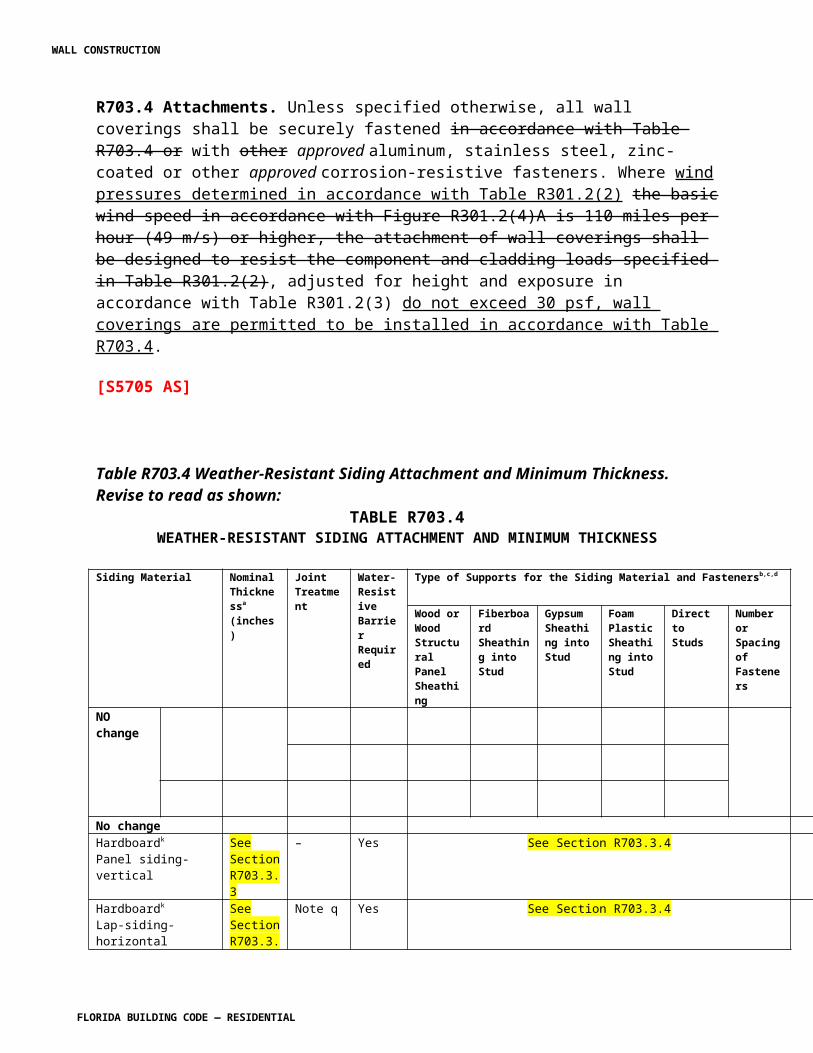
nails and tin-tabs attached to a nailable deck with one row in the field of the sheet with a maximum fastener spacing of 12 in. o.c. (305 mm), and one row at the overlaps fastened 6 in. o.c. (152 mm). Synthetic underlayment shall be fastened in accordance with this section and the manufacturer’s recommendations.
2. One layer underlayment shall comply with ASTM D 226, Type II or ASTM D 4869, Type IV or ASTM D 6757: Underlayment shall be applied shingle fashion, parallel to and starting from the eave and lapped 2 inches (51 mm), fastened with 1 inch (25 mm) round plastic cap, metal cap nails or nails and tin-tabs attached to a nailable deck with two staggered rows in the field of the sheet with a maximum fastener spacing of 12 in. o.c. (305 mm), and one row at the overlaps fastened 6 in. o.c. (152 mm). Synthetic underlayment shall be fastened in accordance with this section and the manufacturer’s recommendations End laps shall be offset by 6 feet (1829 mm).
3. As an alternative, the entire roof deck shall be covered with an approved self-adhering polymer modified bitumen sheet meeting ASTM D 1970 or an approved self-adhering synthetic underlayment installed in accordance with the manufacturer’s installation instructions.
R905.5.4 Material standards. Mineral-surfaced roll roofing shall conform to ASTM D 3909 or ASTM D 6380, Class M or Class WS.
R905.5.5 Application. Mineral-surfaced roll roofing shall be installed in accordance with this chapter and the manufacturer’s installation instructions.
(R5308 AM R1)
Section 905.6 Slate and slate-type shingles. Change to read as shown:
R905.6 Slate and slate-type shingles. The installation of slate and slate-type shingles shall comply with the provisions of this section.
R905.6.1 Deck requirements. Slate shingles shall be fastened to solidly sheathed roofs.
R905.6.2 Deck slope. Slate shingles shall be used only on slopes of four units vertical in 12 units horizontal (33-percent slope) or greater.
R905.6.3 Underlayment. Underlayment shall comply with ASTM D 226, Type I or Type II or ASTM D 4869,Type I II or Type II IV or ASTM D 1970 or ASTM D 6757. Underlayment shall be installed in accordance with the manufacturer’s installation instructions.
WALL CONSTRUCTION
FLORIDA BUILDING CODE — RESIDENTIAL 7.97
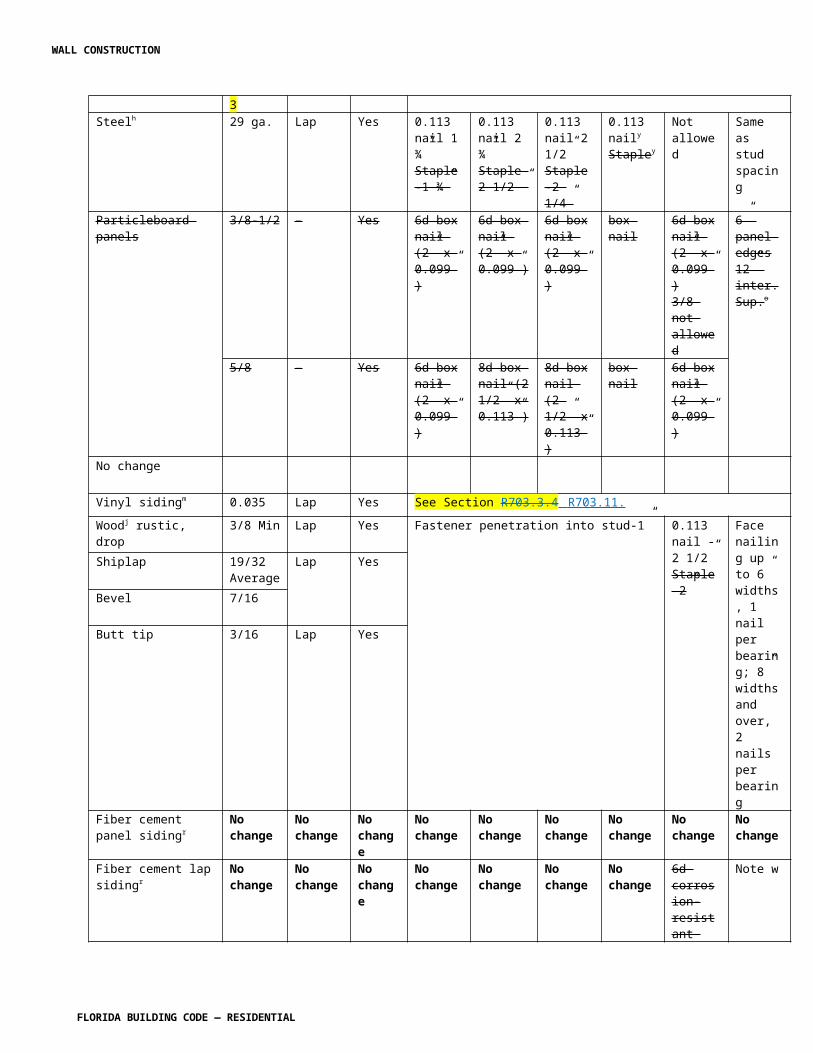
R905.6.3.1 Ice barrier. Reserved.In areas where there has been a history of ice forming along the eaves causing a backup of water as designated in Table R301.2(1), an ice barrier that consists of at least two layers of underlayment cemented together or a self-adhering polymer modified bitumen sheet shall be used in place of normal underlayment and extend from the lowest edges of all roof surfaces to a point at least 24 inches (610 mm) inside the exterior wall line of the building. Exception: Detached accessory structures that contain no conditioned floor area.
R905.6.3.2 Underlayment and high winds. Reserved.Underlayment applied in areas subject to high winds [above 110 mph (49 m/s) in accordance with Figure R301.2(4)A] shall be applied with corrosion-resistant fasteners in accordance with manufacturer’s installation instructions. Fasteners are to be applied along the overlap not farther apart than 36 inches (914 mm) on center. Underlayment installed where the basic wind speed equals or exceeds 120 mph (54 m/s) shall comply with ASTM D 226 Type II. The underlayment shall be attached in a grid pattern of 12 inches (305 mm) between side laps with a 6-inch (152 mm) spacing at the side laps. Underlayment shall be applied in accordance with Section R905.2.7except all laps shall be a minimum of 4 inches (102 mm). Underlayment shall be attached using metal or plastic cap nails with a head diameter of not less than 1 inch (25.4 mm) with a thickness of at least 32-gauge sheet metal. The cap-nail shank shall be a minimum of 12 gauge (0.105 inches) with a length to penetrate through the roof sheathing or a minimum of 3/4 inch (19 mm) into the roof sheathing. Exception: As an alternative, adhered underlayment complying with ASTM D 1970 shall be permitted.
R905.6.3.3 Underlayment Application . Underlayment shall be installed using one of the following methods:
1. Two layer underlayment shall comply with ASTM D 226, Type I or Type II or ASTM D 4869, Type II or Type IV or ASTM D 6757: Apply a 19-inch (483 mm) strip of underlayment felt parallel to and starting at the eaves, fastened sufficiently to hold in place. Starting at the eave, apply 36-inch-wide (914 mm) sheets of underlayment, overlapping successive sheets 19 inches (483 mm), and fastened with 1 inch (25 mm) round plastic cap, metal cap nails or nails and tin-tabs attached to a nailable deck with one row in the field of the sheet with a maximum fastener spacing of 12 in. o.c. (305 mm), and one row at the overlaps fastened 6 in. o.c. (152 mm). Synthetic underlayment shall be fastened in accordance with this section and the manufacturer’s recommendations.
2. One layer underlayment shall comply with ASTM D 226, Type II or ASTM D 4869, Type IV or ASTM D 6757: Underlayment shall be applied shingle fashion, parallel to and starting from the eave and lapped 2 inches (51 mm), fastened with 1 inch (25 mm) round plastic cap, metal cap nails or nails and tin-tabs attached to a nailable deck with two staggered rows in the field of the sheet
WALL CONSTRUCTION
FLORIDA BUILDING CODE — RESIDENTIAL 7.98
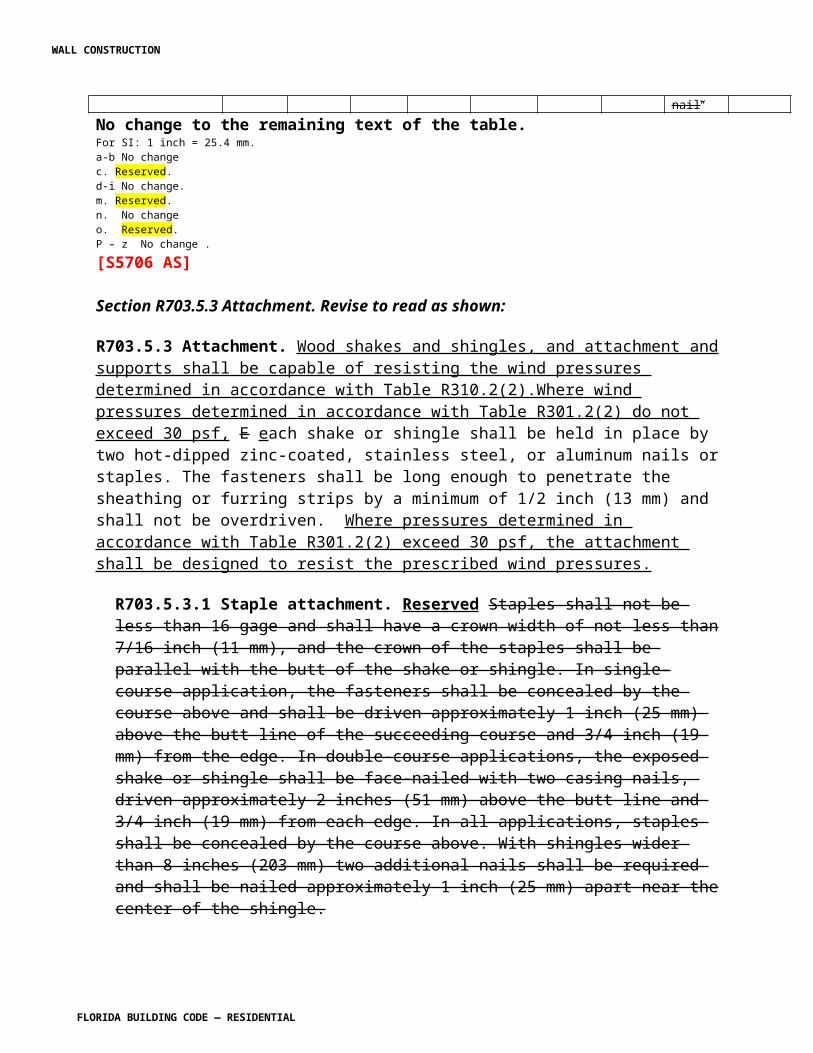
with a maximum fastener spacing of 12 in. o.c. (305 mm), and one row at the overlaps fastened 6 in. o.c. (152 mm). Synthetic underlayment shall be fastened in accordance with this section and the manufacturer’s recommendations End laps shall be offset by 6 feet (1829 mm).
3. As an alternative, the entire roof deck shall be covered with an approved self-adhering polymer modified bitumen sheet meeting ASTM D 1970 or an approved self-adhering synthetic underlayment installed in accordance with the manufacturer’s installation instructions.
R905.6.4 Material standards. Slate shingles shall comply with ASTM C 406.
R905.6.5 Application. Minimum headlap for slate shingles shall be in accordance with Table R905.6.5. Slate shingles shall be secured to the roof with two fasteners per slate. Slate shingles shall be installed in accordance with this chapter and the manufacturer’s installation instructions.
TABLE R905.6.5SLATE SHINGLE HEADLAP
SLOPE HEADLAP (inches)
4:12 ≤ slope < 8:12 48:12 ≤ slope < 20:12 3
Slope ≤ 20:12 2For SI: 1 inch = 25.4 mm.
R905.6.6 Flashing. Flashing and counter flashing shall be made with sheet metal. Valley flashing shall be a minimum of 15 16 inches (381 406 mm) wide. Valley and flashing metal shall be a minimum uncoated thickness of 0.0179-inch (0.5 mm) zinc coated G90 as provided in Table R903.2.1 for nonferrous metal or stainless steel. Chimneys, stucco or brick walls shall have a minimum of two plies of felt for a cap flashing consisting of a 4-inch-wide (102 mm) strip of felt set in plastic cement and extending 1 inch (25 mm) above the first felt and a top coating of plastic cement. The felt shall extend over the base flashing 2 inches (51 mm).
R905.6.7 Slate and slate-type shingles shall be installed in accordance with this chapter and the manufacturer’s installation instructions. The product approval shall state the allowable uplift resistance for the attachment system. The installation of slate and slate-type shingles shall be limited to roofs where the allowable uplift resistance is equal to or greater than the design uplift pressure for the roof listed in Table R301.2(2).
WALL CONSTRUCTION
FLORIDA BUILDING CODE — RESIDENTIAL 7.99
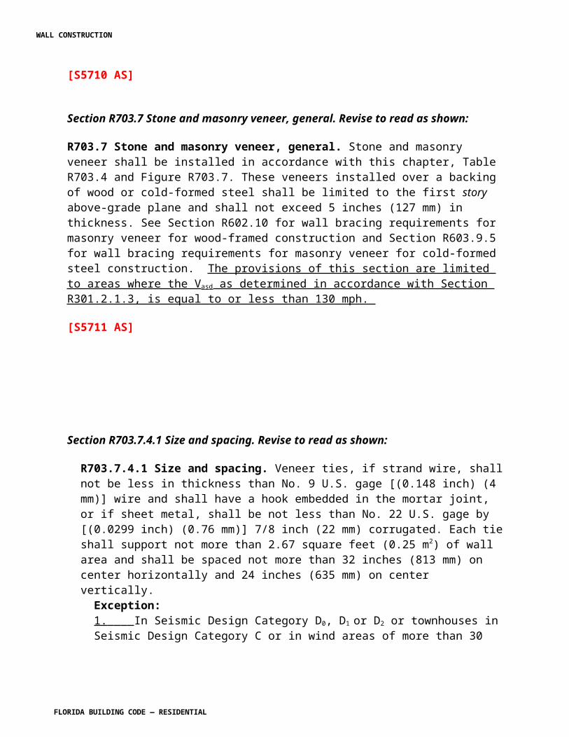
(R5312 AM R1)
Section R905.7 Wood shingles. Change to read as shown:
R905.7 Wood shingles. The installation of wood shingles shall comply with the provisions of this section.
R905.7.1 Deck requirements. Wood shingles shall be installed on solid or spaced sheathing. Where spaced sheathing is used, sheathing boards shall not be less than 1-inch by 4-inch (25.4 mm by 102 mm) nominal dimensions and shall be spaced on centers equal to the weather exposure to coincide with the placement of fasteners.
R905.7.1.1 Solid sheathing required. Reserved. In areas where the average daily temperature in January is 25°F (-4°C) or less, solid sheathing is required on that portion of the roof requiring the application of an ice barrier.
R905.7.2 Deck slope. Wood shingles shall be installed on slopes of three units vertical in 12 units horizontal (25-percent slope) or greater.
R905.7.3 Underlayment. Underlayment shall comply with ASTM D 226, Type I or ASTM D 4869, Type I or II.
R905.7.3.1 Ice barrier. Reserved. In areas where there has been a history of ice forming along the eaves causing a backup of water as designated in Table R301.2(1), an ice barrier that consists of at least two layers of underlayment cemented together or a self-adhering polymer modified bitumen sheet shall be used in lieu of normal underlayment and extend from the lowest edges of all roof surfaces to a point at least 24 inches (610 mm) inside the exterior wall line of the building.
Exception: Detached accessory structures that contain no conditioned floor area.
R905.7.3.2 Underlayment and high winds. Reserved. Underlayment applied in areas subject to high winds [above 110 mph (49 m/s) in accordance with Figure R301.2(4)A] shall be applied with corrosion-resistant fasteners in accordance with manufacturer’s installation instructions. Fasteners are to be applied along the overlap not farther apart than 36 inches (914mm) on center.
Underlayment installed where the basic wind speed equals or exceeds 120 mph (54 m/s) shall comply with ASTM D 226 Type II or ASTM D 4869 Type IV. The underlayment shall be attached in a grid pattern of 12 inches (305 mm) between side laps with a 6-inch (152 mm) spacing at the side laps. Underlayment shall be applied in accordance with Section R905.2.7 except all Head laps shall be a minimum of 4 inches (102 mm). Underlayment shall be attached using metal or plastic cap nails
WALL CONSTRUCTION
FLORIDA BUILDING CODE — RESIDENTIAL
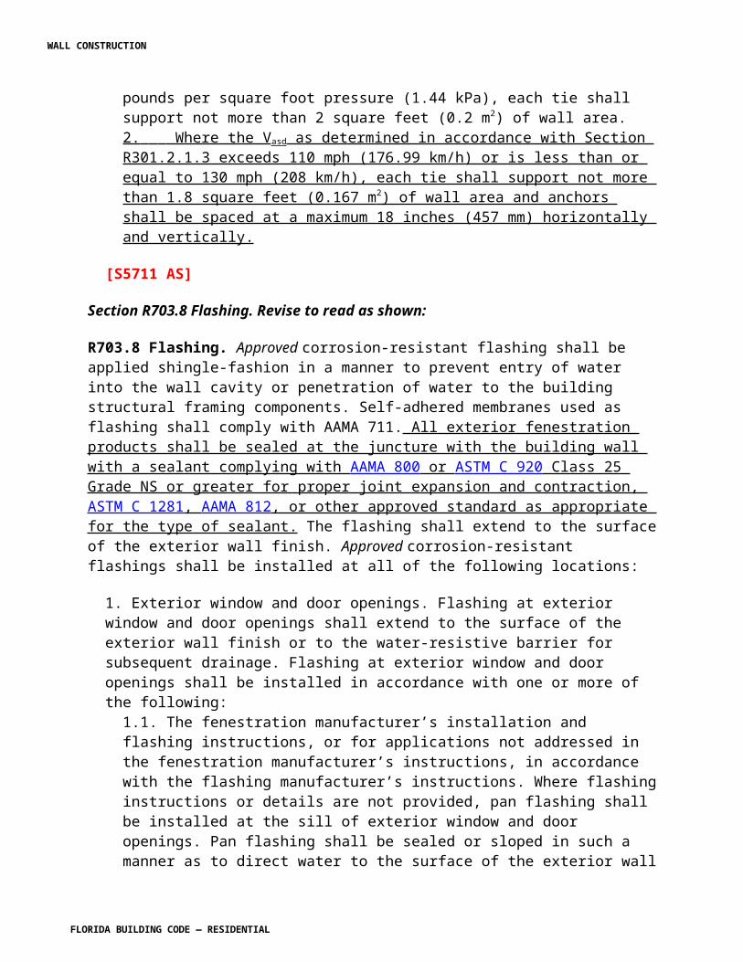
with a head diameter of not less than 1 inch (25.4 mm) with a thickness of at least 32-gauge sheet metal. The cap-nail shank shall be a minimum of 12 gauge (0.105 inches) with a length to penetrate through the roof sheathing or a minimum of 3/4 inch (19 mm) into the roof sheathing.
Exception: As an alternative, adhered underlayment complying with ASTM D 1970 shall be permitted.
R905.7.4 Material standards. Wood shingles shall be of naturally durable wood and comply with the requirements of Table R905.7.4.
TABLE R905.7.4WOOD SHINGLE MATERIAL REQUIREMENTS
MATERIAL MINIMUM GRADES APPLICABLE GRADING RULES
Wood shingles of naturally durable wood 1, 2 or 3 Cedar Shake and Shingle Bureau
R905.7.5 Application Attachment. Wood shingles shall be installed according to this chapter and the manufacturer’s installation instructions. Wood shingles shall be laid with a side lap not less than 11/2 inches (38 mm) between joints in courses, and no two joints in any three adjacent courses shall be in direct alignment. Spacing between shingles shall not be less than 1/4 inch to 3/8 inch (6 mm to 10 mm). Weather exposure for wood shingles shall not exceed those set in Table R905.7.5. Fasteners for wood shingles shall be corrosion resistant with a minimum penetration of 1/2 inch (13 mm) into the sheathing. For sheathing less than 1/2 inch (13 mm) in thickness, the fasteners shall extend through the sheathing. Wood shingles shall be attached to the roof with two fasteners per shingle, positioned no more than 3/4 inch (19 mm) from each edge and no more than 1 inch (25 mm) above the exposure line. Attachment in accordance with Table R905.7.5 shall be used for roofs with a mean roof height of 40 feet or less and in regions with a V asd as determined in accordance with Section R301.2.1.3 to be 100 mph or less
TABLE R905.7.5WOOD SHINGLE WEATHER EXPOSURE AND ROOF SLOPE AND SHAKE
INSTALLATION
ROOFING LENGTH GRADE EXPOSURE (inches)
WALL CONSTRUCTION
FLORIDA BUILDING CODE — RESIDENTIAL
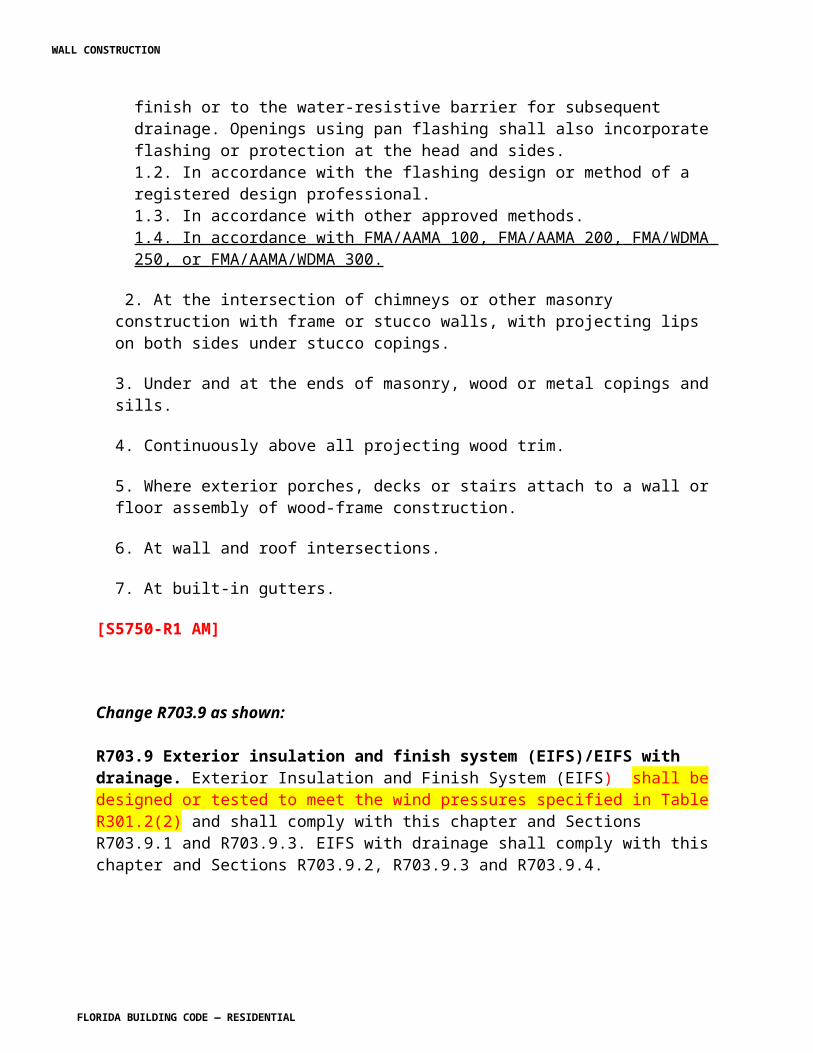
MATERIAL (inches) 3:12 pitch to 4:12 pitch
or steeper
Shingles of naturally durable
wood
16No. 1 33/4 5No. 2 31/2 4No. 3 3 31/2
18No. 1 41/4 51/2
No. 2 4 41/2
No. 3 31/2 4
24No. 1 53/4 71/2
No. 2 51/2 61/2
No. 3 5 51/2
ROOF ITEMWOOD SHINGLES WOOD SHAKES
1. DeckRequirements
Shingles shall be applied to roofs with solid or spaced sheathing. Where spaced sheathing is used,sheathing boards shall not be 4 less than 1”× 4” nominal dimensions and shall be spaced on centerequal to the weather exposure to coincide with the placement of fasteners.
Shakes shall be applied to roofs with solid or spaced sheathing. Where spaced sheathing is used, sheathing boards shall not be less than 1” × 4” nominal dimensionsand shall be spaced on center equal to the weather exposure to coincide with the placement of fasteners. When 1” × 4” spaced sheathing is installed at 10 inches, boards must be installed between the sheathing boards.
2. Interlayment No requirements. Interlayment shall comply with ASTM D 226, Type 1.
3. Underlayment
Underlayment shall comply with ASTM D 226,Type 1.
No requirements.
4. Application --- ---Attachment Fasteners for wood shingles
shall be corrosion resistant with a minimum penetration of 3 / 4 inch into the sheathing. For sheathing less than 1 / 2 inch thick, the fasteners shall extend through the sheathing aminimum of 3 / 8 inch.
Fasteners for wood shakes shall be corrosion resistant with a minimum penetration of 3 / 4 inch into the sheathing. For sheathing less than 1 / 2 inch thick, the fasteners shall extend through the sheathing a minimum of 3 / 8 inch.
WALL CONSTRUCTION
FLORIDA BUILDING CODE — RESIDENTIAL
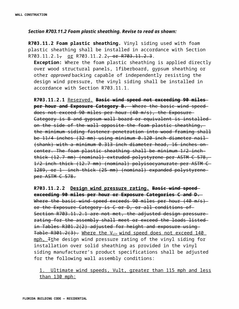
No. of fasteners
Wood shingles shall be attached to the roof with two fasteners per shingle, positioned no more than 3 / 4
inch (19.1 mm) from each edge and no more than 1 1 / 2 inch (38.1 mm) above the exposure line.
Wood shakes shall be attached to the roof with two fasteners per shake, positioned no more than 1 inch (25.4 mm) from each edge and no more than 1 1 / 2 inches(38.1 mm) above the exposure line
For SI: 1 inch = 25.4 mm
R905.7.6 Valley flashing Attachment for V asd as determined in accordance with Section R301.2.1.3 greater than 100 mph. Roof flashing shall be not less than No. 26 gage [0.019 inches (0.5 mm)] corrosion-resistant sheet metal and shall extend 10 inches (254 mm) from the centerline each way for roofs having slopes less than 12 units vertical in 12 units horizontal (100-percent slope), and 7 inches (178 mm) from the centerline each way for slopes of 12 units vertical in 12 units horizontal and greater. Sections of flashing shall have an end lap of not less than 4 inches (102 mm). Wood shingles installed in accordance with Table R905.7.5 and the requirements of R905.7.6 have an allowable uplift resistance of 45 psf. The installation of wood shingles shall be limited to roofs where the allowable uplift resistance is equal to or greater than the design uplift pressure for the roof listed in Table R301.2(2).
R905.7.6.1 Fasteners.
R905.7.6.1.1 Nails. N ails to attach the wood shakes shall be 3d stainless-steel ring-shank nails. The nails shall have sufficient length to penetrate through the wood shakes and shall penetrate through the sheathing.
R905.7.6.1.2 Screws. Screws to attach the battens to the framing shall be No. 8 by 2 1 / 2 inches (64 mm) long corrosion resistant wood screws. Wood screws shall be corrosion resistant screw s conforming to ANSI/ASME B 18.6.1. The corrosion resistance shall meet ASTM A 641, Class 1 or an equal corrosion resistance by coating, electro galvanization, mechanical galvanization, stainless steel, nonferrous metal or other suitable corrosion resistant material.
R905.7.6.1.3 Wood battens. 1 × 4 wood battens shall be attached to the wood joists with 2 screws per joist. The first batten shall be located 6 inches (152 mm) from the outer edge of the wood joist. Second batten shall be spaced 1- 1 / 4 inches
WALL CONSTRUCTION
FLORIDA BUILDING CODE — RESIDENTIAL
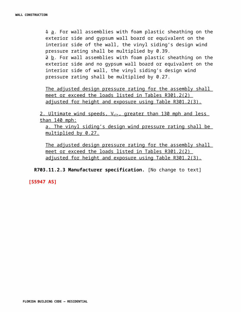
(32 mm) from the first batten. The remaining battens shall be spaced a maximum 2 inches (51 mm) apart, except the last one which shall be spaced no greater than 3 / 4 inches (19 mm) from the previous batten.
R905.7.6.1.4 Shingles. Shingles shall be attached to the battens with 2 nails for each shingle placed 1 1 / 2 inch (38 mm) above the exposure line. The nails shall be 3 / 4 to 1 inch (19 to 25 mm) from the shingle edges.
R905.7.7 Label required Application. Each bundle of shingles shall be identified by a label of an approved grading or inspection bureau or agency. Wood shingles shall be installed according to this chapter and the manufacturer’s installation instructions. Weather exposure for wood shingles shall not exceed those set in Table R905.7.7.
TABLE R905.7.7WOOD SHINGLE WEATHER EXPOSURE AND ROOF SLOPE
ROOFINGMATERIAL
LENGTH(inches) GRADE
EXPOSURE (inches)3:12 pitch
to< 4:12
4:12 pitch orsteeper
Shingles ofnaturally durablewood
16No. 1 3 3 / 4 5No. 2 3 1 / 2 4No. 3 3 3 1 / 2
18No. 1 4 1 / 4 5 1 / 2
No. 2 4 4 1 / 2
No. 3 3 1 / 2 4
24No. 1 5 3 / 4 7 1 / 2
No. 2 5 1 / 2 6 1 / 2
No. 3 5 5 1 / 2
For SI: 1 inch = 25.4 mm.
R905.7.8 Flashing. At the juncture of the roof and vertical surfaces, flashing and counter flashing shall be provided in accordance with the manufacturer’s installation instructions, and where of metal, shall not be less than 0.017-inch (0.48 mm) (No. 26 galvanized sheet gage) corrosion-resistant metal.
R905.7.8.1 Valley flashing. Roof flashing shall be not less than No. 26 gage [0.017 inches (0.48 mm)] corrosion-resistant sheet metal and shall extend 10 inches (254 mm) from the centerline each way for roofs having slopes less than 12 units vertical in 12 units horizontal (100-percent slope), and 7 inches (178 mm) from the centerline each way for slopes of 12 units vertical in 12 units horizontal and greater. Sections of
WALL CONSTRUCTION
FLORIDA BUILDING CODE — RESIDENTIAL
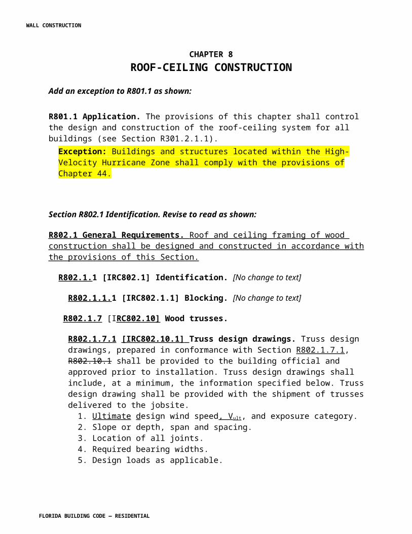
flashing shall have an end lap of not less than 4 inches (102 mm).
R905.7.9 Label required. Each bundle of shingles shall be identified by a label of an approved grading or inspection bureau or agency.
(R5315 AM R1)
Section 9R905.8 Wood shakes. Change to read as shown:
R905.8 Wood shakes. The installation of wood shakes shall comply with the provisions of this section.
R905.8.1 Deck requirements. Wood shakes shall be used only on solid or spaced sheathing. Where spaced sheathing is used, sheathing boards shall not be less than 1-inch by 4-inch (25 mm by 102 mm) nominal dimensions and shall be spaced on centers equal to the weather exposure to coincide with the placement of fasteners. Where 1-inch by 4-inch (25 mm by 102 mm) spaced sheathing is installed at 10 inches (254 mm) on center, additional 1-inch by 4-inch (25 mm by 102 mm) boards shall be installed between the sheathing boards.
R905.8.1.1 Solid sheathing required. Reserved.In areas where the average daily temperature in January is 25°F (-4°C) or less, solid sheathing is required on that portion of the roof requiring an ice barrier
R905.8.2 Deck slope. Wood shakes shall only be used on slopes of three four (4) units vertical in twelve (12) units horizontal (25 33-percent slope) or greater.
R905.8.3 Underlayment. Underlayment shall comply with ASTM D 226, Type I or Type II or ASTM D 4869, Type I or II or Type IV.
R905.8.3.1 Ice barrier. Reserved.In areas where there has been a history of ice forming along the eaves causing a backup of water as designated in Table R301.2(1), an ice barrier that consists of at least two layers of underlayment cemented together or a self-adhering polymer modified bitumen sheet shall be used in place of normal underlayment and extend from the lowest edges of all roof surfaces to a point at least 24 inches (610 mm) inside the exterior wall line of the building. Exception: Detached accessory structures that contain no conditioned floor area.
R905.8.3.2 Underlayment and high winds. Reserved.Underlayment applied in areas subject to high winds [above 110 mph (49 m/s) in accordance with Figure R301.2(4)A] shall be applied with corrosion-resistant fasteners in accordance with manufacturer’s installation instructions. Fasteners are to be applied along the overlap not farther apart than 36 inches (914 mm) on center. Underlayment installed where the basic wind speed equals or exceeds 120 mph (54
WALL CONSTRUCTION
FLORIDA BUILDING CODE — RESIDENTIAL
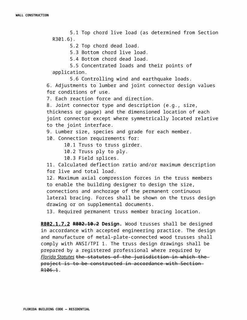
m/s) shall comply with ASTM D 226 Type II. The underlayment shall be attached in a grid pattern of 12 inches (305 mm) between side laps with a 6-inch (152 mm) spacing at the side laps. Underlayment shall be applied in accordance with Section R905.2.7except all laps shall be a minimum of 4 inches (102 mm). Underlayment shall be attached using metal or plastic cap nails with a head diameter of not less than 1 inch (25.4 mm) with a thickness of at least 32-gauge sheet metal. The cap-nail shank shall be a minimum of 12 gauge (0.105 inches) with a length to penetrate through the roof sheathing or a minimum of 3/4 inch (19 mm) into the roof sheathing. Exception: As an alternative, adhered underlayment complying with ASTM D 1970 shall be permitted.
R905.8.3.3 Underlayment Application. Underlayment shall be installed using one of the following methods:
1. Two layer underlayment shall comply with ASTM D 226, Type I or Type II or ASTM D 4869, Type II or Type IV: Apply a 19-inch (483 mm) strip of underlayment felt parallel to and starting at the eaves, fastened sufficiently to hold in place. Starting at the eave, apply 36-inch-wide (914 mm) sheets of underlayment, overlapping successive sheets 19 inches (483 mm), and fastened with 1 inch (25 mm) round plastic cap, metal cap nails or nails and tin-tabs attached to a nailable deck with one row in the field of the sheet with a maximum fastener spacing of 12 in. o.c. (305 mm), and one row at the overlaps fastened 6 in. o.c. (152 mm).
2. One layer underlayment shall comply with ASTM D 226, Type II or ASTM D 4869, Type IV: Underlayment shall be applied shingle fashion, parallel to and starting from the eave and lapped 2 inches (51 mm), fastened with 1 inch (25 mm) round plastic cap, metal cap nails or nails and tin-tabs attached to a nailable deck with two staggered rows in the field of the sheet with a maximum fastener spacing of 12 in. o.c. (305 mm), and one row at the overlaps fastened 6 in. o.c. (152 mm). End laps shall be offset by 6 feet (1829 mm).
R905.8.3.4 Interlayment. Interlayment shall comply with ASTM D 226, Type I.
R905.8.4 Interlayment Attachment. Attachment in accordance with Table R905.7.5 shall be used for roofs with a mean roof height of 40 feet or less and in regions with a as determined in accordance with Section R301.2.1.3, of 100 mph or less.
Interlayment shall comply with ASTM D 226, Type I.
R905.8.5 Material standards. Wood shakes shall comply with the requirements of Table R905.8.5.
TABLE R905.8.5WOOD SHAKE MATERIAL REQUIREMENTS
WALL CONSTRUCTION
FLORIDA BUILDING CODE — RESIDENTIAL
MATERIALMINIMUM GRADES
APPLICABLE GRADING RULES
Wood shakes of naturally durable wood 1 Cedar Shake and Shingle Bureau
Taper sawn shakes of naturally durable wood 1 or 2 Cedar Shake and Shingle Bureau
Preservative-treated shakes and shingles of naturally durable wood 1 Cedar Shake and Shingle Bureau
Fire-retardant-treated shakes and shingles of naturally durable wood 1 Cedar Shake and Shingle Bureau
Preservative-treated taper sawn shakes of Southern pine treated in accordance with AWPA Standard U1 (Commodity Specification A, Use Category 3B and Section 5.6)
1 or 2 Forest Products Laboratory of theTexas Forest Services
R905.8.6 Application. Reserved.Wood shakes shall be installed according to this chapter and the manufacturer’s installation instructions. Wood shakes shall be laid with a side lap not less than 11/2
inches (38 mm) between joints in adjacent courses. Spacing between shakes in the same course shall be 3/8 inch to 5/8 inch (9.5 mm to 15.9 mm) for shakes and tapersawn shakes of naturally durable wood and shall be 3/8 inch to 5/8 inch (9.5 mm to 15.9 mm) for preservative-treated taper sawn shakes. Weather exposure for wood shakes shall not exceed those set forth in Table R905.8.6. Fasteners for wood shakes shall be corrosion-resistant, with a minimum penetration of 1/2 inch (12.7 mm) into the sheathing. For sheathing less than 1/2 inch (12.7 mm) thick, the fasteners shall extend through the sheathing. Wood shakes shall be attached to the roof with two fasteners per shake, positioned no more than 1 inch (25 mm) from each edge and no more than 2 inches (51 mm) above the exposure line.
TABLE R905.8.6WOOD SHAKE WEATHER EXPOSURE AND ROOF SLOPE
Reserved.
ROOFING MATERIAL
LENGTH (inches) GRADE
EXPOSURE (inches)
4:12 pitch or steeperShakes of naturally durable wood
18 No. 1 71/2
24 No. 1 10a
Preservative-treated taper sawn shakes of Southern Yellow Pine
18 No. 1 71/2
24 No. 1 1018 No. 2 51/2
24 No. 2 71/2
Taper-sawn shakes of 18 No. 1 71/2
WALL CONSTRUCTION
FLORIDA BUILDING CODE — RESIDENTIAL
naturally durable wood24 No. 1 1018 No. 2 51/2
24 No. 2 71/2
For SI: 1 inch = 25.4 mm.a. For 24-inch by 3/8-inch handsplit shakes, the maximum exposure is 71/2 inches.
R905.8.7 Shake placement Attachment for V asd as determined in accordance with Section R301.2.1.3 greater than 100 mph. Wood shakes installed in accordance with Table R905.7.5 and the requirements of R905.8.7 have an allowable uplift resistance of 90 psf. The installation of wood shakes shall be limited to roofs where the allowable uplift resistance is equal to or greater than the design uplift pressure for the roof listed in Table R301.2(2). The starter course at the eaves shall be doubled and the bottom layer shall be either 15-inch (381 mm), 18-inch (457 mm) or 24-inch (610 mm) wood shakes or wood shingles. Fifteen-inch (381 mm) or 18-inch (457 mm) wood shakes may be used for the final course at the ridge. Shakes shall be interlaid with 18-inch-wide (457 mm) strips of not less than No. 30 felt shingled between each course in such a manner that no felt is exposed to the weather by positioning the lower edge of each felt strip above the butt end of the shake it covers a distance equal to twice the weather exposure.
R905.8.7.1 Fasteners.
R905.8.7.1.1 Nails . Nails to attach the wood shakes shall be 6d stainless-steel ring-shank nails. The nails shall have sufficient length to penetrate through the wood shakes and shall penetrate through the sheathing.
R905.8.7.1.2 Screws. Screws to attach the battens to the framing shall be No. 8 by 2 1 / 2 inches long corrosion resistant wood screws. Wood screws shall be corrosion resistant screws conforming to ANSI/ASME B 18.6.1. The corrosion resistance shall meet ASTM A 641, Class 1 or an equal corrosion resistance by coating, electro galvanization, mechanical galvanization, stainless steel, nonferrous metal or other suitable corrosion resistant material.
R905.8.7.1.3 Wood battens. 1 × 6 wood battens shall be attached to the wood joists with 2 screws per joist. The first batten shall be located 6 inches from the outer edge of the wood joist. The second batten shall be spaced 1- 1 / 4 inches from the first batten. The remaining battens shall be spaced a maximum 2 inches apart, except the last one, which shall be spaced no greater than 3 / 4 inches from the previous batten.
R905.8.7.1.4 Shakes. Shakes shall be attached to the battens with 2 nails for each shake placed 1 1 / 2 inch above the exposure line. The nails shall be 3 / 4 to 1 inch from the shake edges.
WALL CONSTRUCTION
FLORIDA BUILDING CODE — RESIDENTIAL
R905.8.8 Valley flashing Application. Wood shakes shall be laid with a side lap not less than 1 1 / 2 inches (38 mm) between joints in adjacent courses. Spacing between shakes in the same course shall be 3 / 8 to 5 / 8 inches (9.5 to 15.9 mm) for shakes and taper sawn shakes of naturally durable wood and shall be 1 / 4 to 3 / 8 inch (6.4 to 9.5 mm) for preservative taper sawn shakes. Weather exposure for wood shakes shall not exceed those set in Table R905.8.8.Roof valley flashing shall not be less than No. 26 gage [0.019 inch (0.5 mm)] corrosion-resistant sheet metal and shall extend at least 11 inches (279 mm) from the centerline each way. Sections of flashing shall have an end lap of not less than 4 inches (102 mm).
TABLE R905.8.8WOOD SHAKE WEATHER EXPOSURE AND ROOF SLOPE
ROOFING MATERIALLENGTH
(inches) GRADEEXPOSURE (inches)4:12 pitch or steeper
Shakes of naturally durablewood
18 No. 1 7 1 / 2
24 No. 1 10 a
Preservative-treated tapersawn shakes of SouthernYellow Pine
18 No. 1 7 1 / 2
24 No. 1 1018 No. 2 5 1 / 2
24 No. 2 7 1 / 2
Taper-sawn shakes ofnaturally durable wood
18 No. 1 7 1 / 2
24 No. 1 1018 No. 2 5 1 / 2
24 No. 2 7 1 / 2
For SI: 1 inch = 25.4 mm.a. For 24-inch by 3 / 8-inch handsplit shakes, the maximum exposure is 7 1 / 2 inches.
R905.8.9 Label required. Each bundle of shakes shall be identified by a label of an approved grading or inspection bureau or agency.
R905.8.10 Flashing. At the juncture of the roof and vertical surfaces, flashing and counter flashing shall be provided in accordance with the manufacturer’s installation instructions, and where of metal, shall not be less than 0.017-inch (0.48 mm) (No. 26 galvanized sheet gage) corrosion-resistant metal.
R905.8.10.1 Valley flashing. Valley flashing shall extend at least 11 inches (279 mm) from the centerline each way and have a splash diverter rib not less than 1 inch (25 mm) high at the flow line formed as part of the flashing. Sections of flashing
WALL CONSTRUCTION
FLORIDA BUILDING CODE — RESIDENTIAL
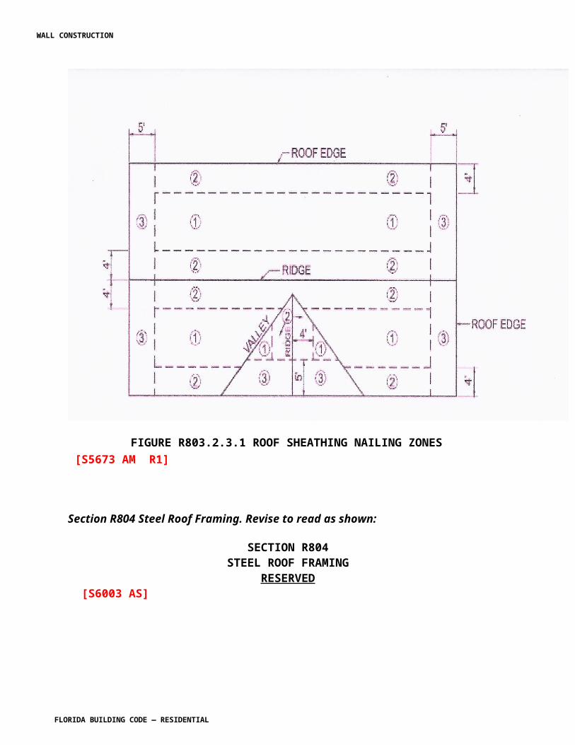
shall have an end lap of not less than 4 inches (102 mm). For roof slopes of four (4) units vertical in twelve (12) units horizontal (33-percent slope) and over, the valley flashing shall have a 36-inch-wide (914 mm) underlayment of one layer of ASTM D 226 Type I underlayment running the full length of the valley, in addition to other required underlayment per Table R903.2.1 Valley flashing and flashing metal shall be a minimum thickness as provided in Table R903.2.1 for nonferrous metal or stainless steel.
(R5314 AM R1)
Section R905.9 Built-up roofs. Change to read as shown:
R905.9 Built-up roofs. The installation of built-up roofs shall comply with the provisions of this section.
R905.9.1 Slope. Built-up roofs shall have a design slope of a minimum of one-fourth unit vertical in 12 units horizontal (2-percent slope) for drainage, except for coal-tar built-up roofs, which shall have a design slope of a minimum one-eighth unit vertical in 12 units horizontal (1-percent slope).
R905.9.2 Material standards. Built-up roof covering materials shall comply with the standards in Table R905.9.2 or UL 55A.
R905.9.2.1 Red rosin paper shall be used when the membrane is applied directly to a wood deck or cementitious fiber decks.
TABLE R905.9.2BUILT-UP ROOFING MATERIAL STANDARDS
MATERIAL STANDARD STANDARD
Acrylic coatings used in roofing ASTM D 6083Aggregate surfacing ASTM D 1863Asphalt adhesive used in roofing ASTM D 3747Asphalt cements used in roofing ASTM D 2822; D 3019; D 4586Asphalt-coated glass fiber base sheet ASTM D 4601
Asphalt coatings used in roofing ASTM D 1227; D 2823; D 2824; D 4479
Asphalt glass felt ASTM D 2178Asphalt primer used in roofing ASTM D 41Asphalt-saturated and asphalt-coated organic felt base sheet ASTM D 2626
WALL CONSTRUCTION
FLORIDA BUILDING CODE — RESIDENTIAL
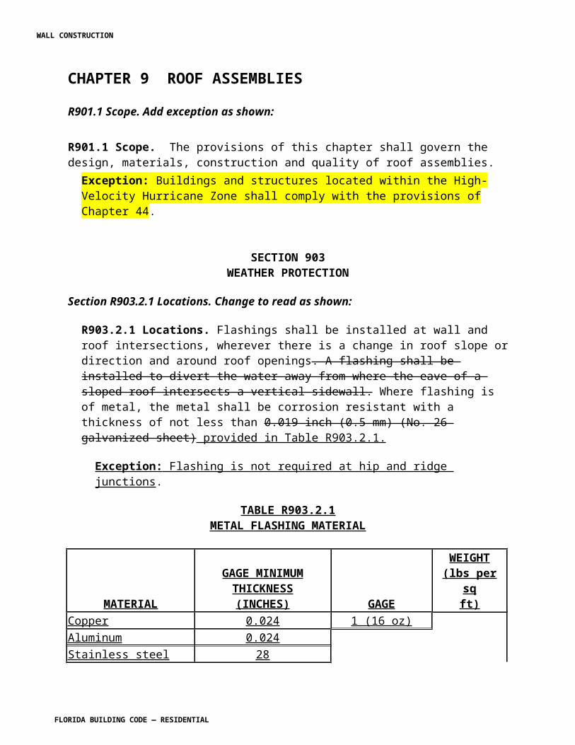
Asphalt-saturated organic felt (perforated) ASTM D 226Asphalt used in roofing ASTM D 312Coal-tar cements used in roofing ASTM D 4022; D 5643Coal-tar primer used in roofing, dampproofing and waterproofing ASTM D 43
Coal-tar saturated organic felt ASTM D 227Coal-tar used in roofing ASTM D 450, Type I or IIGlass mat, coal tar ASTM D 4990Glass mat, venting type ASTM D 4897Mineral-surfaced inorganic cap sheet ASTM D 3909Thermoplastic fabrics used in roofing ASTM D 5665; D 5726R905.9.3 Application. [No change to IRC text] (R5303 AS)
Section 905.10 Metal roof panels. Change to read as shown:
R905.10 Metal roof panels. The installation of metal roof panels shall comply with the provisions of this section.
R905.10.1 Deck requirements. Metal roof panel roof coverings shall be applied to solid or spaced sheathing, except where the roof covering is specifically designed to be applied to spaced supports.
R905.10.2 Slope. Minimum slopes for metal roof panels shall comply with the following:
1. The minimum slope for lapped, nonsoldered-seam metal roofs without applied lap sealant shall be three units vertical in 12 units horizontal (25-percent slope).
2. The minimum slope for lapped, nonsoldered-seam metal roofs with applied lap sealant shall be one-half vertical unit in 12 units horizontal (4-percent slope). Lap sealants shall be applied in accordance with the approved manufacturer’s installation instructions.
3. The minimum slope for standing-seam roof systems shall be one-quarter unit vertical in 12 units horizontal (2-percent slope).
R905.10.3 Material standards. Metal-sheet roof covering systems that incorporate supporting structural members shall be designed in accordance with the International Building Code Florida Building Code, Building . Metal-sheet roof coverings installed over structural decking shall comply with Table R905.10.3(1) 4.4. The materials used for metal-sheet roof coverings shall be naturally corrosion resistant or provided with corrosion resistance in accordance with the standards and minimum thicknesses shown
WALL CONSTRUCTION
FLORIDA BUILDING CODE — RESIDENTIAL
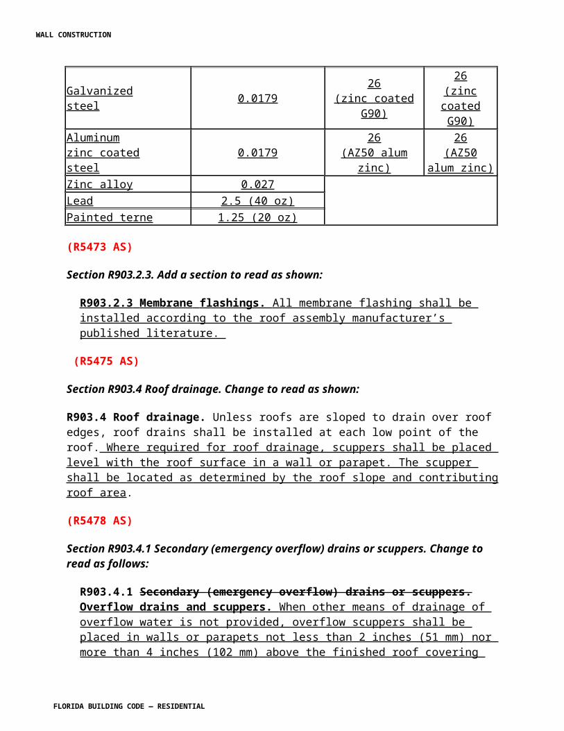
in Table R905.10.3(2) 4.4.
TABLE R905.10.3(1)METAL ROOF COVERING STANDARDS
Reserved.
ROOF COVERING TYPE STANDARD APPLICATION RATE/THICKNESS
Galvanized steel ASTM A 653 G90 Zinc coatedStainless steel ASTM A 240, 300 Series alloysSteel ASTM A 924Lead-coated copper ASTM B 101
Cold-rolled copperASTM B 370 minimum 16 oz/sq ft and 12 oz/sq ft high-yield copper for metal-sheet roof-covering systems; 12 oz/sq ft for preformed metal shingle systems.
Hard lead 2 lb/sq ftSoft lead 3 lb/sq ft
AluminumASTM B 209, 0.024 minimum thickness for roll-formed panels and 0.019-inch minimum thickness for pressformed shingles.
Terne (tin) and terne-coated stainless
Terne coating of 40 lb per double base box, field painted where applicable in accordance with manufacturer’s installation instructions.
Zinc0.027 inch minimum thickness: 99.995% electrolytic high-grade zinc with alloy additives of copper (0.08 - 0.20%), titanium (0.07% - 0.12%) and aluminum (0.015%).
For SI: 1 ounce per square foot = 0.305 kg/m2, 1 pound per square foot = 4.214 kg/m2, 1 inch = 25.4 mm, 1 pound = 0.454 kg.
TABLE R905.10.3(2)MINIMUM CORROSION RESISTANCE
Reserved.
55% aluminum-zinc alloy coated steel ASTM A 792 AZ 50
5% aluminum alloy-coated steel ASTM A 875 GF60Aluminum-coated steel ASTM A 463 T2 65Galvanized steel ASTM A 653 G-90Prepainted steel ASTM A 755a
a. Paint systems in accordance with ASTM A 755 shall be applied over steel products with corrosion-resistant coatings complying with ASTM A 792, ASTM A 875, ASTM A 463, or ASTM A 653.
R905.10.4 Attachment. Metal roof panels shall be secured to the supports in
WALL CONSTRUCTION
FLORIDA BUILDING CODE — RESIDENTIAL
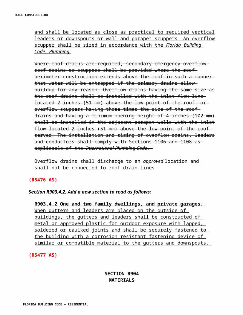
accordance with this chapter and the manufacturer’s installation instructions. Metal roofing fastened directly to steel framing shall be attached by approved fasteners. In the absence of manufacturer’s installation instructions, t The following fasteners shall be used:
1. Galvanized fasteners shall be used for galvanized roofs.2. Hard C copper ,brass, bronze, or copper alloy or 300 series stainless steel fasteners shall be used for copper roofs.3. Stainless steel fasteners are acceptable for all types of metal roofs.4. Aluminum-zinc coated fasteners are acceptable for aluminum-zinc coated roofs.
R905.10.5 Underlayment. Underlayment shall comply with ASTM D 226, Type I or Type II or ASTM D 4869, Type II or Type IV or ASTM D 1970 or ASTM D 6757.
R905.10.5.1 Underlayment and high winds. Reserved . Underlayment applied in areas subject to high winds [above 110 mph (49 m/s) in accordance with Figure R301.2(4)A] shall be applied with corrosion-resistant fasteners in accordance with manufacturer’s installation instructions. Fasteners are to be applied along the overlap not farther apart than 36 inches (914 mm) on center.
Underlayment installed where the basic wind speed equals or exceeds 120 mph (54 m/s) shall comply with ASTM D 226 Type II. The underlayment shall be attached in a grid pattern of 12 inches (305 mm) between side laps with a 6-inch (152 mm) spacing at the side laps. Underlayment shall be applied in accordance with Section R905.2.7except all laps shall be a minimum of 4 inches (102 mm). Underlayment shall be attached using metal or plastic cap nails with a head diameter of not less than 1 inch (25.4 mm) with a thickness of at least 32-gauge sheet metal. The cap-nail shank shall be a minimum of 12 gauge (0.105 inches) with a length to penetrate through the roof sheathing or a minimum of 3/4 inch (19 mm) into the roof sheathing.
Exception: As an alternative, adhered underlayment complying with ASTM D 1970 shall be permitted.
R905.10.5.2 Underlayment Application. Underlayment shall be installed using one of the following methods:
1. Two layer underlayment shall comply with ASTM D 226, Type I or Type II or ASTM D 4869, Type II or Type IV or ASTM D 6757: Apply a 19-inch (483 mm) strip of underlayment felt parallel to and starting at the eaves, fastened sufficiently to hold in place. Starting at the eave, apply 36-inch-wide (914 mm) sheets of underlayment, overlapping successive sheets 19 inches (483 mm), and fastened with 1 inch (25 mm) round plastic cap, metal cap nails or nails and tin-tabs attached to a nailable deck with one row in the field of the sheet with a maximum fastener spacing of 12 in. o.c. (305 mm), and one row at the overlaps fastened 6 in. o.c. (152 mm). Synthetic underlayment shall be fastened in accordance with this section and the manufacturer’s recommendations.
WALL CONSTRUCTION
FLORIDA BUILDING CODE — RESIDENTIAL
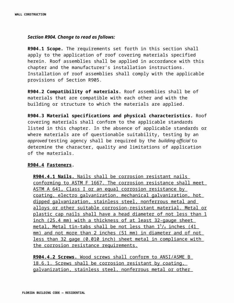
2. One layer underlayment shall comply with ASTM D 226, Type II or ASTM D 4869, Type IV or ASTM D 6757: Underlayment shall be applied shingle fashion, parallel to and starting from the eave and lapped 2 inches (51 mm), fastened with 1 inch (25 mm) round plastic cap, metal cap nails or nails and tin-tabs attached to a nailable deck with two staggered rows in the field of the sheet with a maximum fastener spacing of 12 in. o.c. (305 mm), and one row at the overlaps fastened 6 in. o.c. (152 mm). Synthetic underlayment shall be fastened in accordance with this section and the manufacturer’s recommendations End laps shall be offset by 6 feet (1829 mm).
3. As an alternative, the entire roof deck shall be covered with an approved self-adhering polymer modified bitumen sheet meeting ASTM D 1970 or an approved self-adhering synthetic underlayment installed in accordance with the manufacturer’s installation instructions.
(R5306 AM R1)
Section R905.11 Modified bitumen roofing. Change to read as shown:
R905.11 Modified bitumen roofing. The installation of modified bitumen roofing shall comply with the provisions of this section.
R905.11.1 Slope. Modified bitumen membrane roofs shall have a design slope of a minimum of one-fourth unit vertical in 12 units horizontal (2-percent slope) for drainage.
R905.11.2 Material standards. Modified bitumen roof coverings shall comply with the standards in Table R905.11.2.
TABLE R905.11.2MODIFIED BITUMEN ROOFING MATERIAL STANDARDS
MATERIAL STANDARD
Acrylic coating ASTM D 6083Asphalt adhesive ASTM D 3747Asphalt cement ASTM D 3019Asphalt coating ASTM D 1227; D 2824Asphalt primer ASTM D 41Modified bitumen roofmembrane
ASTM D 6162; D 6163; D 6164;D 6222; D 6223; D 6298; D 6509C
WALL CONSTRUCTION
FLORIDA BUILDING CODE — RESIDENTIAL
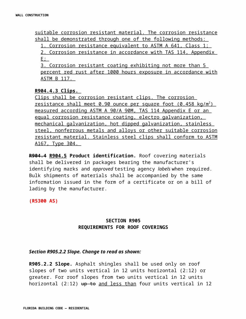
SB 37â€"GP€"56M
R905.11.3 Application. Modified bitumen roofs shall be installed according to this chapter and the manufacturer’s installation instructions. The approved allowable uplift resistance for the modified bitumen roof shall be equal to or greater than the uplift resistance for the roof based on Table R301.2(2).
(R5309 AS)
Section R905.12 Thermoset single-ply roofing. Change to read as shown:
R905.12 Thermoset single-ply roofing. The installation of thermoset single-ply roofing shall comply with the provisions of this section.
R905.12.1 Slope. Thermoset single-ply membrane roofs shall have a design slope of a minimum of one-fourth unit vertical in 12 units horizontal (2-percent slope) for drainage.
R905.12.2 Material standards. Thermoset single-ply roof coverings shall comply with ASTM D 4637, ASTM D 5019 or CGSB 37-GP-52M.
R905.12.3 Application. Thermoset single-ply roofs shall be installed according to this chapter and the manufacturer’s installation instructions. The approved allowable uplift resistance for the thermoset single-ply membrane roof shall be equal to or greater than the uplift resistance for the roof based on Table R301.2(2).
(R5310 AS)
Section R905.13 Thermoplastic sing-ply roofing. Change to read as shown:
R905.13 Thermoplastic single-ply roofing. The installation of thermoplastic single-ply roofing shall comply with the provisions of this section.
R905.13.1 Slope. Thermoplastic single-ply membrane roofs shall have a design slope of a minimum of one-fourth unit vertical in 12 units horizontal (2-percent slope).
R905.13.2 Material standards. Thermoplastic single-ply roof coverings shall comply with ASTM D 4434, ASTM D 6754, ASTM D 6878 or CGSB CAN/CGSB 37.54.
R905.13.3 Application. Thermoplastic single-ply roofs shall be installed according to this chapter and the manufacturer’s installation instructions. The approved allowable uplift resistance for the thermoplastic single-ply roof shall be equal to or greater than the uplift resistance for the roof based on Table R301.2(2).
WALL CONSTRUCTION
FLORIDA BUILDING CODE — RESIDENTIAL
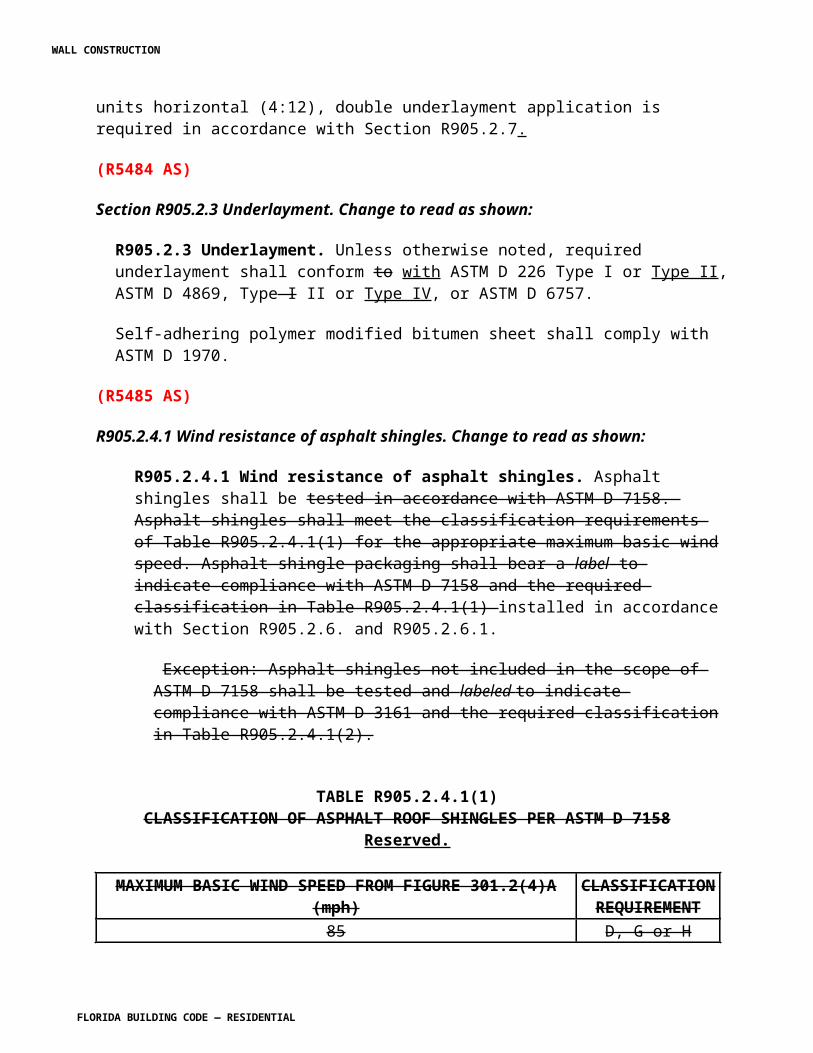
(R5311 AS)
Section R905.14 Sprayed polyurethane foam roofing. Change to read as shown:
R905.14 Sprayed polyurethane foam roofing. The installation of sprayed polyurethane foam roofing shall comply with the provisions of this section.
R905.14.1 Slope. Sprayed polyurethane foam roofs shall have a design slope of a minimum of one-fourth unit vertical in 12 units horizontal (2-percent slope) for drainage.
R905.14.2 Material standards. Spray-applied polyurethane foam insulation shall comply with ASTM C 1029, Type III or IV.
R905.14.3 Application. Foamed-in-place roof insulation shall be installed in accordance with this chapter and the manufacturer’s installation instructions. A liquid-applied protective coating that complies with Table R905.14.3 Section R905.15 shall be applied no less than 2 hours nor more than 72 hours following the application of the foam. The approved allowable uplift resistance for the sprayed polyurethane foam roofing shall be equal to or greater than the uplift resistance for the roof based on Table R301.2(2).
TABLE R905.14.3PROTECTIVE COATING MATERIAL STANDARDS
Reserved.
MATERIAL STANDARD
Acrylic coating ASTM D 6083Silicone coating ASTM D 6694Moisture-cured polyurethane coating ASTM D 6947
R905.14.4 Foam plastics. Foam plastic materials and installation shall comply with Section R316.
(R5313 AM R3)
Section R905.15 Liquid-applied roofing. Change to read as shown:
WALL CONSTRUCTION
FLORIDA BUILDING CODE — RESIDENTIAL
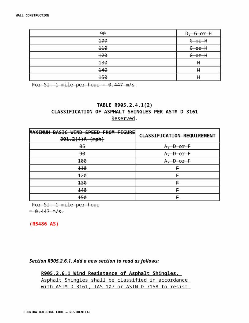
R905.15 Liquid-applied roofing. The installation of liquid-applied roofing shall comply with the provisions of this section.
R905.15.1 Slope. Liquid-applied roofing shall have a design slope of a minimum of one-fourth unit vertical in 12 units horizontal (2-percent slope).
R905.15.2 Material standards. Liquid-applied roofing shall comply with ASTM C 836, C 957, D 1227, D 3468, D 6083, D 6694 or D 6947.
R905.15.3 Application. Liquid-applied roof coatings shall be installed according to this chapter and the manufacturer’s installation instructions. The approved allowable uplift resistance for the liquid-applied coatings shall be equal to or greater than the uplift resistance for the roof based on Table R301.2(2).
(R5305 AS)
Section R905.16 Photovoltaic modules/shingles. Change to read as shown:
R905.16 Building integrated P photovoltaic roofing modules/shingles. The installation of building integrated photovoltaic roofing modules/shingles shall comply with the provisions of this section.
R905.16.1 Material standards. Building integrated P photovoltaic roofing modules/shingles shall be listed and labeled in accordance with UL 1703.
R905.16.2 Attachment. Building integrated P photovoltaic roofing modules/shingles shall be attached in accordance with the manufacturer’s installation instructions.
R905.16.3 Wind resistance. Building integrated P photovoltaic roofing modules/shingles shall be tested in accordance with procedures and acceptance criteria in ASTM D 3161 or TAS 107. Building integrated P photovoltaic roofing modules/shingles shall comply with the classification requirements of Table R905.2 4.1(2) .6.1 for the appropriate maximum basic wind speed. Building integrated P photovoltaic roofing modules/shingle packaging shall bear a label to indicate compliance with the procedures in ASTM D 3161 or TAS 107 and the required classification from Table R905.2 4.1(2) .6.1.
(R5552 AS)
Section R905.17. Add a section to read as shown:
WALL CONSTRUCTION
FLORIDA BUILDING CODE — RESIDENTIAL
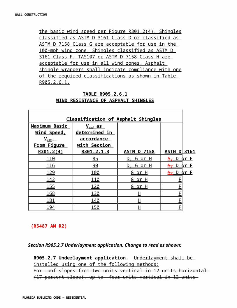
R905.17 Photovoltaic systems. Rooftop mounted photovoltaic systems shall be designed in accordance with this section.
R905.17.1 Wind resistance. Rooftop mounted photovoltaic systems shall be designed for wind loads for component and cladding in accordance with Chapter 16 using an effective wind area based on the dimensions of a single unit frame.
R905.17.2 Fire classification. Rooftop mounted photovoltaic systems shall have the same fire classification as the roof assembly required by Section R902.
R905.17.3 Installation. Rooftop mounted photovoltaic systems shall be installed in accordance with the manufacturer's installation instructions.
R905.17.4 Photovoltaic panels and modules. Photovoltaic panels and modules mounted on top of a roof shall be listed and labeled in accordance with UL 1703 and shall be installed in accordance with the manufacturer's installation instructions.
(R5553 AS)
SECTION R907REROOFING
Section R907 Reroofing. Change to read as shown:
R907.1 General. Materials and methods of application used for re-covering or replacing an existing roof covering shall comply with the requirements of Chapter 9 of the Florida Building Code, Residential.
Exception: Reroofing shall not be required to meet the minimum design slope requirement of one-quarter unit vertical in 12 units horizontal (2-percent slope) in Section R905 for roofs that provide positive roof drainage.
R907.2 Structural and construction loads. The structural roof components shall be capable of supporting the roof covering system and the material and equipment loads that will be encountered during installation of the roof covering system.
R907.3 Recovering versus replacement. New roof coverings shall not be installed without first removing all existing layers of roof coverings where any of the following conditions exist occur:
WALL CONSTRUCTION
FLORIDA BUILDING CODE — RESIDENTIAL
1. Where the existing roof or roof covering is water-soaked or has deteriorated to the point that the existing roof or roof covering is not adequate as a base for additional roofing.
2. Where the existing roof covering is wood shingle or shake, slate, clay, cement or asbestos-cement tile.
3. Where the existing roof has two or more applications of any type of roof covering.
4. When blisters exist in any roofing, unless blisters are cut or scraped open and remaining materials secured down before applying additional roofing.
5. Where the existing roof is to be used for attachment for a new roof system and compliance with the securement provisions of Section R905 cannot be met.
Exceptions:
1. Complete and separate roofing systems, such as standing-seam metal roof systems, that are designed to transmit the roof loads directly to the building’s structural system and that do not rely on existing roofs and roof coverings for support, shall not require the removal of existing roof coverings.2. Reserved. Installation of metal panel, metal shingle and concrete and clay tile roof coverings over existing wood shake roofs shall be permitted when the application is in accordance with Section R907.4. 3. The application of new protective coating over existing spray polyurethane foam roofing systems shall be permitted without tear-off of existing roof coverings.4. Reserved. Where the existing roof assembly includes an ice barrier membrane that is adhered to the roof deck, the existing ice barrier membrane shall be permitted to remain in place and covered with an additional layer of ice barrier membrane in accordance with Section R905. 5. Roof Coating. Application of elastomeric and or maintenance coating systems over existing asphalt shingles shall be in accordance with the shingle manufacturer’s approved installation instructions.
R907.4 Roof recovering. Reserved. Where the application of a new roof covering over wood shingle or shake roofs creates a combustible concealed space, the entire existing surface shall be covered with gypsum board, mineral fiber, glass fiber or other approved materials securely fastened in place.
R907.5 Reinstallation of materials. Existing slate, clay or cement tile shall be permitted for reinstallation, except that damaged, cracked or broken slate or tile shall not be reinstalled. Any existing flashings, edgings, outlets, vents or similar devices that are a part of the assembly shall be replaced when rusted, damaged or deteriorated. Aggregate surfacing materials shall not be reinstalled.
WALL CONSTRUCTION
FLORIDA BUILDING CODE — RESIDENTIAL
R907.6 Flashings. Flashings shall be reconstructed in accordance with approved manufacturer’s installation instructions. Metal flashing to which bituminous materials are to be adhered shall be primed prior to installation.
R907.7 When a roof covering on an existing site-built single-family residential structure is removed and replaced, the following procedures shall be permitted to be performed by the roofing contractor:
(a) Roof-decking attachment shall be as required by Section R907.7.1.(b) A secondary water barrier shall be provided as required by Section R907.7.2.
Exception : Single family residential structures permitted subject to the Florida Building Code are not required to comply with this section.
R907.7.1 Roof decking attachment for site-built single-family residential structures. For site-built single-family residential structures the fastening shall be in accordance with Section R907.7.1.1 or R907.7.1.2 as appropriate for the existing construction. 8d nails shall be a minimum of 0.113 inch (2.9 mm) in diameter and shall be a minimum of 2 1 / 4 inch (57 mm) long to qualify for the provisions of this section for existing nails regardless of head shape or head diameter.
R907.7.1.1 Roof decking consisting of sawn lumber or wood planks up to 12” wide and secured with at least two nails (minimum size 8d) to each roof framing member it crosses shall be deemed to be sufficiently connected. Sawn lumber or wood plank decking secured with smaller fasteners than 8d nails or with fewer than two nails (minimum size 8d) to each framing member it crosses shall be deemed sufficiently connected if fasteners are added such that two clipped head, round head, or ring shank nails (minimum size 8d) are in place on each framing member it crosses.
R907.7.1.2 For roof decking consisting of wood structural panels, fasteners and spacing required in columns 3 and 4 of Table R907.7.1.2 are deemed to comply with the indicated design wind speed range. Wood structural panel connections retrofitted with a two part urethane based closed cell adhesive sprayed onto the joint between the sheathing and framing members are deemed to comply provided testing using the manufacturer’s recommended application on panels connected with 6d smooth shank nails at no more than a 6-inch edge and 12-inch field spacing demonstrate an uplift resistance of a minimum of 200 psf.
Supplemental fasteners as required by Table R907.7.1.2 shall be 8d ring shank nails with round heads and the following minimum dimensions:
1. 0.113-inch nominal shank diameter.2. Difference between root and ring diameter a minimum of 5% of root nail diameter. Ring diameter a minimum of 0.012-inch greater than shank diameter.3. 16 to 20 rings per inch.4. A minimum 0.280-inch full round head diameter.5. Ring shank to extend a minimum of 1 1 / 2 inches from the tip of the nail.6. Minimum 2 3/8 - 1 / 4 inch nail length.
WALL CONSTRUCTION
FLORIDA BUILDING CODE — RESIDENTIAL
TABLE R907.7.1.2SUPPLEMENT FASTENERS AT PANEL EDGES AND INTERMEDIATE FRAMING
EXISTING FASTENERS
EXISTING SPACING
Vasd 110 MPH OR LESS SUPPLEMENTAL
FASTENERSPACING SHALLBE NO GREATER
THAN
Vasd GREATER THAN 110 MPH
SUPPLEMENTALFASTENER SPACING
SHALL BE NOGREATER THAN
Staples or 6d Any 6?o.c. b 6?o.c. b 8d clippedhead, roundhead, smooth orring shank
6?o.c. orless None necessary None necessary
8d clippedhead, roundhead, smooth orring shank
Greaterthan
6?o.c.6?o.c. a 6?o.c. a
For SI: 1 inch = 25.4 mm.a. Maximum spacing determined based on existing fasteners and supplemental fasteners.b. Maximum spacing determined based on supplemental fasteners only.c. Vasd shall be determined in accordance with Section 1609.3.1 of the Florida Building Code, Building or Section R301.2.1.3 of the Florida Building Code, Residential.
R907.7.2 Roof secondary water barrier for site-built single family residential structures. A secondary water barrier shall be installed using one of the following methods when roof covering is removed and replaced:
1. In either HVHZ or Non-HVHZ regions:
a) All joints in structural panel roof sheathing or decking shall be covered with a minimum 4 inch (102 mm) wide strip of self-adhering polymer modified bitumen tape applied directly to the sheathing or decking. The deck and self-adhering polymer modified bitumen tape shall be covered with one of the underlayment systems approved for the particular roof covering to be applied to the roof.
b) The entire roof deck shall be covered with an approved asphalt impregnated 30# felt underlayment or approved synthetic underlayment installed with nails and tin-tabs in accordance with Sections R4402.7.2, R4402.7.3, or R4402.7.4 of the Florida Building Code, Residential. (No additional underlayment shall be required over the top of this sheet.) The synthetic underlayment shall be fastened in accordance with the manufacturer’s recommendations.
WALL CONSTRUCTION
FLORIDA BUILDING CODE — RESIDENTIAL
2. Outside the High Velocity Hurricane Zone:
a) The entire roof deck shall be covered with an approved self-adhering polymer modified bitumen sheet meeting ASTM D 1970 or an approved self-adhering synthetic underlayment installed in accordance with the manufacturer’s installation instructions. No additional underlayment shall be required on top of this sheet for new installations.
b) An underlayment system approved for the particular roof covering shall be applied with the following modification:
(1) For roof slopes that require one layer of underlayment, a layer of approved asphalt impregnated ASTM D 226 Type I or Type II, ASTM D 4869, Type II or Type IV underlayment or approved synthetic underlayment shall be installed. The felt is to be fastened with 1 inch (25 mm) round plastic cap, metal cap nails or nails and tin-tabs attached to a nailable deck with two staggered rows in the field of the sheet with a maximum fastener spacing of 12 in. o.c. (305 mm), and one row at the overlaps fastened 6 in. o.c. (152 mm). Synthetic underlayment shall be fastened in accordance with this section and the manufacturer’s recommendations.
(2) For roof slopes that require two layers of underlayment, an approved asphalt impregnated ASTM D 226 Type I or Type II, ASTM D 4869, Type II or Type IV underlayment shall be installed in a shingle–fashion and lapped 19 inch (483 mm) and fastened with 1 inch (25 mm) round plastic cap, metal cap nails or nails and tin- tabs, attached to a nailable deck with one row in the field of the sheet with a maximum fastener spacing of 12 in. o.c. (305 mm), and one row at the overlaps fastened 6 in. o.c. (152 mm). An approved synthetic underlayment shall be installed in accordance with this section and the manufacturer’s installation instruction. (No additional underlayment shall be required over the top of this sheet.)
Exceptions:
1. Roof slopes < 2:12 having a continuous roof system shall be deemed to comply with Section R907.7.2 requirements for a secondary water barrier.2. Clay and concrete tile roof systems installed as required by the Florida Building Code, Residential are deemed to comply with the requirements of Section R907.7.2 for Secondary Water Barriers.
R907.8 When a roof covering on an existing site-built-single-family residential structure is removed and replaced on a building that is located in the wind-borne debris region as defined in the Florida Building Code, Building and that has an insured value of $300,000 or more or, if the building is uninsured or for which documentation of insured value is not presented, has a just valuation for the structure for purposes of ad valorem taxation of $300,000 or more:
(a) Roof to wall connections shall be improved as required by Section R907.8.1(b) Mandated retrofits of the roof-to-wall connection shall not be required beyond a 15 percent increase in the cost of re-roofing.
WALL CONSTRUCTION
FLORIDA BUILDING CODE — RESIDENTIAL
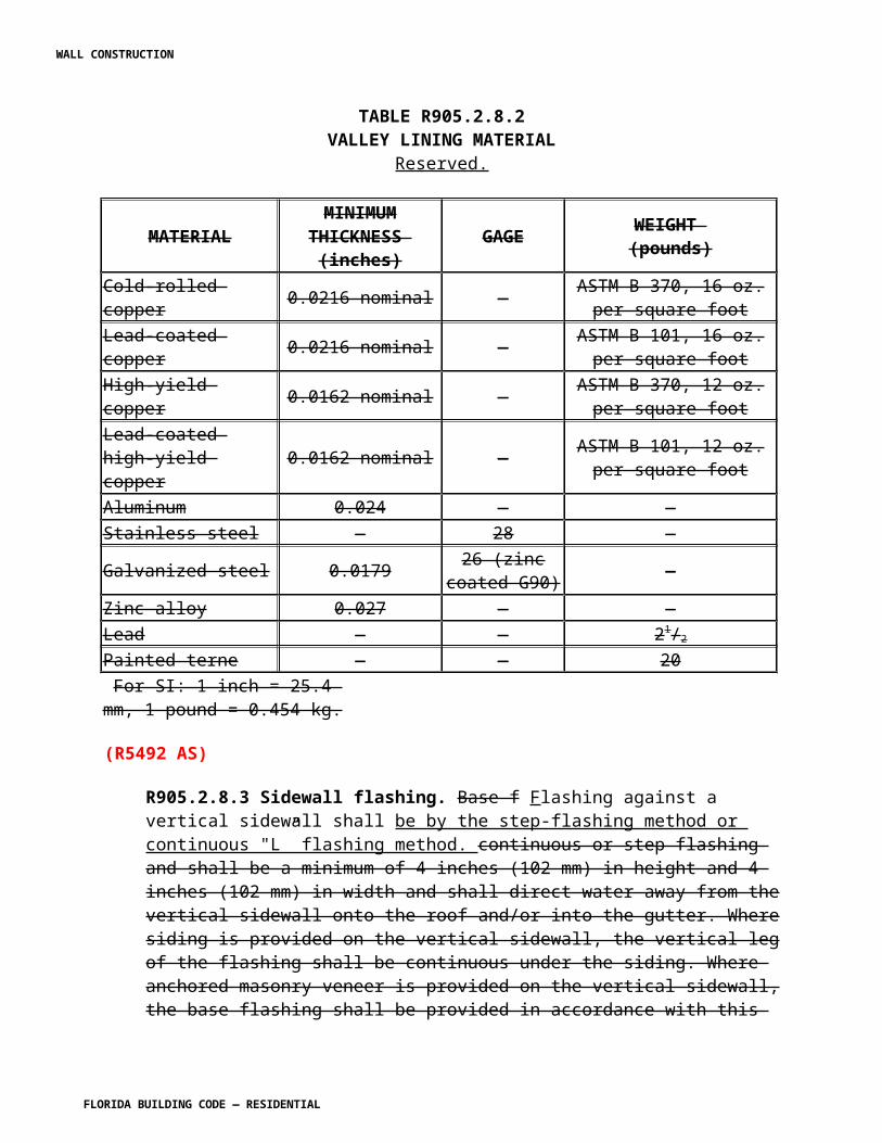
Exception: Single-family residential structures permitted subject to the Florida Building Code are not required to comply with this section.
R907.8.1 Roof-to-wall connections for site-built single-family residential structures. Where required by Section R907.8, the intersection of roof framing with the wall below shall provide sufficient resistance to meet the uplift loads specified in Table R907.8.1 either because of existing conditions or through retrofit measures. As an alternative to an engineered design, the prescriptive retrofit solutions provided in Sections R907.8.1.1 through R907.8.1.7 shall be accepted as meeting the mandated roof-to-wall retrofit requirements.
Exceptions:
1. Where it can be demonstrated (by code adoption date documentation and permit issuance date) that roof-to-wall connections and/or roof-to-foundation continuous load path requirements were required at the time of original construction.2. Roof-to-wall connections shall not be required unless evaluation and installation of connections at gable ends or all corners can be completed for 15 percent of the cost of roof replacement.
WALL CONSTRUCTION
FLORIDA BUILDING CODE — RESIDENTIAL
TABLE R907.8.1REQUIRED UPLIFT CAPACITIES FOR ROOF-TO-WALL CONNECTIONS a, b
(POUNDS PER LINEAR FOOT)
ULTIMATEDESIGN WIND
SPEED, Vult
ROOF SPAN (feet)
OVERHANGS12 20 24 28 32 36 40
Within 6 feet of building corner
85 -69.85 -116.42
-139.70
-162.99 -186.27 -209.55 -232.84 -27
90 -82.67 -137.78
-165.34
-192.90 -220.45 -248.01 -275.57 -
30.3
100 -110.51
-184.18
-221.01
-257.85 -294.68 -331.52 -368.36 -
37.4
110 -141.27
-235.45
-282.55
-329.64 -376.73 -423.82 -470.91 -
45.3
120 -174.97
-291.62
-349.94
-408.26 -466.59 -524.91 -583.23 -
53.9
130 -211.60
-352.66
-423.19
-493.72 -564.26 -634.79 -705.32 -
63.2
140 -251.15
-418.59
-502.31
-586.02 -669.74 -753.46 -837.18 -
73.3
150 -293.64
-489.40
-587.28
-685.16 -783.04 -880.92 -978.80 -
84.2
170 -387.40
-645.67
-774.81
-903.94
-1033.08
-1162.21 -1291.35 -108
Greater than 6 feet from building corner
85 -39.10 -65.17 -78.20 -91.24 -104.27 -117.30 -130.34 -27
90 -48.20 -80.33 -96.39 -112.46 -128.52 -144.59 -160.66 -
30.3
100 -67.95 -113.24
-135.89
-158.54 -181.19 -203.84 -226.49 -
37.4
110 -89.78 -149.63
-179.55
-209.48 -239.40 -269.33 -299.25 -
45.3
120 -113.68
-189.47
-227.37
-265.26 -303.16 -341.05 -378.94 -
53.9
130 -139.67
-232.78
-279.34
-325.90 -372.45 -419.01 -465.57 -
63.2
140 -167.74
-279.56
-335.47
-391.38 -447.29 -503.21 -559.12 -
73.3
150 -197.88
-329.80
-395.76
-461.72 -527.68 -593.64 -659.60 -
84.2
170 -264.41
-440.68
-528.81
-616.95 -705.08 -793.22 -881.35 -108
For SI: 1 foot = 304.8 mm; 1 pound per linear foot = 1.488 kg/m; 1 mile per hour = 0.305 m/s.a. The uplift loads are pounds per lineal foot of building length. For roof uplift connections
WALL CONSTRUCTION
FLORIDA BUILDING CODE — RESIDENTIAL
multiply by 1.33 for framing spaced 16 inches on center and multiply by 2 for framing spaced 24 inches on center.b. The uplift loads do not account for the effects of overhangs. The magnitude of the above loads shall be increased by adding the overhang loads found in the table. The overhang loads are also based on framing spaced 12 inches on center. The overhang loads given shall be multiplied by the overhang projection and added to the roof uplift value in the table.c. For Ultimate design wind speeds, Vult, greater than 170 mph, wind uplift forces shall be determined in accordance with Florida Building Code, Residential, Section R802.3 or ASCE 7. d. Ultimate Design Wind Speeds determined from Figure 1609A in the Florida Building Code, Building or Figure R301.2(4) in the Florida Building Code, Residential.
R907.8.1.1 Access for Retrofitting Roof to Wall Connections. These provisions are not intended to limit the means for gaining access to the structural elements of the roof and wall for the purposes of retrofitting the connection. The retrofit of roof to wall connections can be made by access through the area under the eave, from above through the roof, or from the interior of the house. Methods for above access include removal of roof panels or sections thereof or removal of portions of roof paneling at selected locations large enough for access, viewing, and installing the retrofit connectors and fasteners.
Where panels or sections are removed, the removed portions shall not be reused. New paneling shall be used and fastened as in new construction.
Holes shall be deemed adequately repaired if a patch of paneling is installed with no gap greater than 1 / 2 inch (13 mm) between the patch and the existing sheathing and if the patch is supported using one of the following methods.
a) Solid 1 1 / 2 inch lumber shall fully support the patch and shall be secured to the existing sheathing with #8 by 1 1 / 4 inch screws spaced a minimum of 3 inches (76 mm) around the perimeter with screws a minimum of 3 / 4 inch from the near edge of the hole. The patch shall be secured to the lumber with #8 × 1- 1 / 4 inch screws spaced on a grid no greater than 6 inches by 6 inches (152 mm × 152 mm) with no fewer than 2 screws.
b) Holes that extend horizontally from roof framing member to adjacent roofing framing member that are less than or equal to 7 inches (178 mm) wide along the slope of the roof shall be supported by minimum of 2 × 4 lumber whose face is attached to each roofing framing members using a minimum of 2 each 3-inch (76 mm) long fasteners (#8 screws or 10d common nails) connecting the two. The patch shall have attached to its bottom, running horizontally, a minimum 2 × 4 either flat wise or on edge secured with #8 × 1 1 / 4 inch screws a maximum of 4 inches (102 mm) on center and no more distant from the end of the added lumber than 3 inches (76 mm). The patch shall be secured with two #8 × 1-1 1 / 4 inch screws to each support member.
WALL CONSTRUCTION
FLORIDA BUILDING CODE — RESIDENTIAL
R907.8.1.2 Partially inaccessible straps. Where part of a strap is inaccessible, if the portion of the strap that is observed is fastened in compliance with these requirements, the inaccessible portion of the strap shall be presumed to comply with these requirements.
R907.8.1.3 Prescriptive method for gable roofs on a wood frame wall. The anchorage of each of the exposed rafters or truss within 6 feet (1829 mm) of the corner along the exterior wall on each side of each gable end shall be inspected. Wherever a strap is missing or an existing strap has fewer than four fasteners on each end, approved straps, ties or right angle brackets with a minimum uplift capacity of 500 lbs (740 kg) shall be installed that connect each rafter or truss to the top plate below. Adding fasteners to existing straps shall be allowed in lieu of adding a new strap provided the strap is manufactured to accommodate at least 4 fasteners at each end. Wherever access makes it possible (without damage of the wall or soffit finishes), both top plate members shall be connected to the stud below using a stud to plate connector with a minimum uplift capacity of 500 lbs (740 kg). Use of straps that connect directly from the rafter or truss to the wall stud below shall be allowed as an alternate provided the two members align with no more than 1 1 / 2 inches (38 mm) offset.
R907.8.1.4 Prescriptive method for gable roofs on a masonry wall. The anchorage of each of the exposed rafters or truss within 6 feet (1829 mm) of the corner along the exterior wall on each side of each gable end shall be inspected. Wherever a strap is missing or an existing strap has fewer than four fasteners on each end, approved straps, ties or right angle gusset brackets with a minimum uplift capacity of 500 lbs (740 kg) shall be installed that connect each rafter or truss to the top plate below or directly to the masonry wall using approved masonry screws of a length and diameter recommended by the manufacturer. In the absence of manufacturer’s recommendations, screws shall provide at least a 2 1 / 2 inch (64 mm) embedment into the concrete or masonry. When the straps or right angle gusset brackets are attached to a wood sill plate, the sill plate shall be anchored to the concrete masonry wall below. This anchorage shall be accomplished by installing 1 / 4-inch diameter masonry screws, each with supplementary 1 / 4-inch washer, having sufficient length to develop a 2 1 / 2 inch (64 mm) embedment into the concrete and masonry. These screws shall be installed within 4 inches (102 mm) of the truss or rafter on both sides of each interior rafter or truss and on the accessible wall side of the gable end truss or rafter.
R907.8.1.5 Prescriptive method for hip roofs on a wood frame wall. Unless it is possible to verify through non-destructive inspection or from plans prepared by a design professional that the roof structure is anchored at least as well as outlined below, access shall be provided at a minimum to the hip rafter (commonly known as a "king jack”), to the hip girder and at each corner of the hip roof. The hip rafter (commonly known as a "king jack”), the hip girder and the rafters/trusses adjacent to the hip girder that are not anchored with a strap having at least four fasteners on each end, shall be connected to the top plate below using a strap or a right angle gusset bracket having a minimum uplift capacity of 500 lbs (740 kg). Adding fasteners to existing straps shall be allowed in lieu of adding a new strap provided the strap is manufactured to accommodate at least 4 fasteners at each end. Wherever access makes it possible (without damage of the wall or soffit finishes), both top plate members shall be connected to the stud below using a stud to plate
WALL CONSTRUCTION
FLORIDA BUILDING CODE — RESIDENTIAL
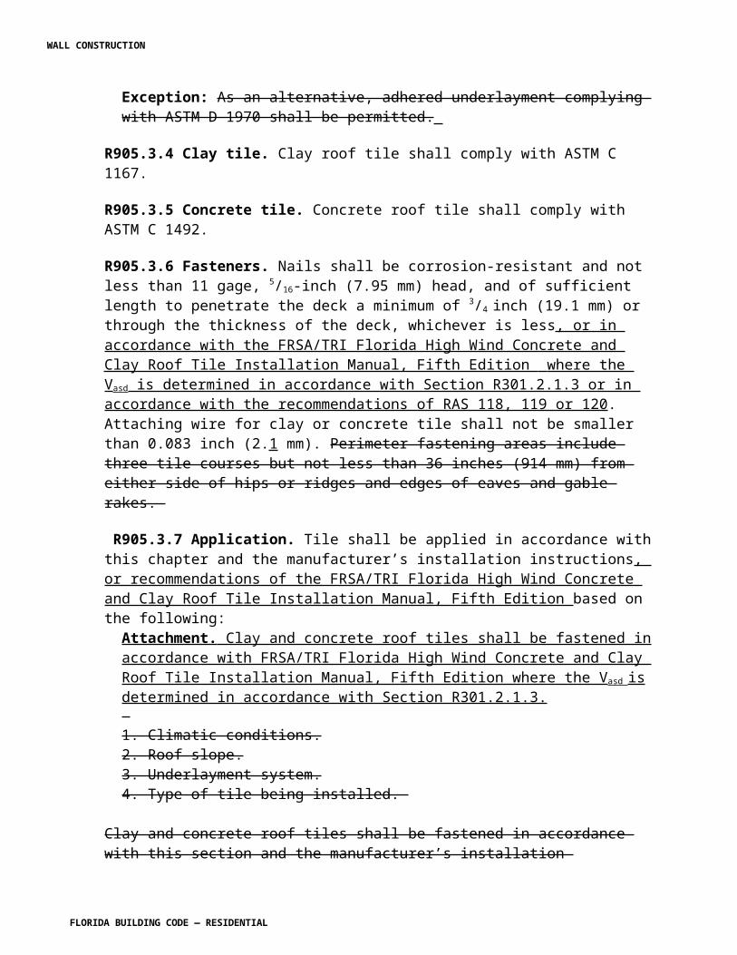
connector with a minimum uplift capacity of 500 lbs (740 kg). Use of straps that connect directly from the hip rafter, hip girder or adjacent rafters/trusses to the wall stud below shall be allowed as an alternate provided the two members align with no more than 1 1 / 2 inch (38 mm) offset.
R907.8.1.6 Prescriptive method for hip roofs on a masonry wall. Unless it is possible to verify through non-destructive inspection or from plans prepared by a design professional that the roof structure is anchored at least as well as outlined below, access shall be provided at a minimum to the hip rafter (commonly known as a "king jack”), to the hip girder and at each corner of the hip roof. The hip rafter (commonly known as a "king jack”), the hip girder and the rafters/trusses adjacent to the hip girder that are not anchored with a strap having at least four fasteners on each end, shall be connected to the concrete masonry wall below using approved straps or right angle gusset brackets with a minimum uplift capacity of 500 lbs (740 kg). Adding fasteners to existing straps shall be allowed in lieu of adding a new strap provided the strap is manufactured to accommodate at least 4 fasteners at each end. The straps or right angle gusset brackets shall be installed such that they connect each rafter or truss to the top plate below or directly to the masonry wall using approved masonry screws of a length and diameter recommended by the manufacturer. In the absence of manufacturer’s recommendations, screws shall provide at least 2 1 / 2 inches (64 mm) embedment into the concrete or masonry. When the straps or right angle gusset brackets are attached to a wood sill plate, the sill plate shall be anchored to the concrete masonry wall below. This anchorage shall be accomplished by installing 1 / 4-inch (6 mm) diameter masonry screws, each with supplementary 1 / 4-inch (6 mm) washer, with sufficient length to develop a 2 1 / 2 inch (64 mm) embedment into the concrete and masonry. These screws shall be installed within 4 inches (102 mm) of the truss or rafter on both sides of each interior rafter or truss and on the accessible wall side of the gable end truss or rafter.
R907.8.1.7 Priorities for mandated roof-to-wall retrofit expenditures. Priority shall be given to connecting the exterior corners of roofs to walls where the spans of the roofing members are greatest. For houses with both hip and gable roof ends, the priority shall be to retrofit the gable end roof-to-wall connections unless the width of the hip end is more than 1.5 times greater than the width of the gable end. When considering priorities for houses with both hip and gable roof ends, and the fifteen percent of the cost of roof replacement is sufficient to complete all of the prioritized elements pursuant to this section, but is not sufficient to complete all of the non-prioritized elements, then no portion of complete retrofit of the non-prioritized element is required.
(R5554 AM R2)
\
CHAPTER 10. CHIMNEYS AND FIREPLACES. [No change]
WALL CONSTRUCTION
FLORIDA BUILDING CODE — RESIDENTIAL
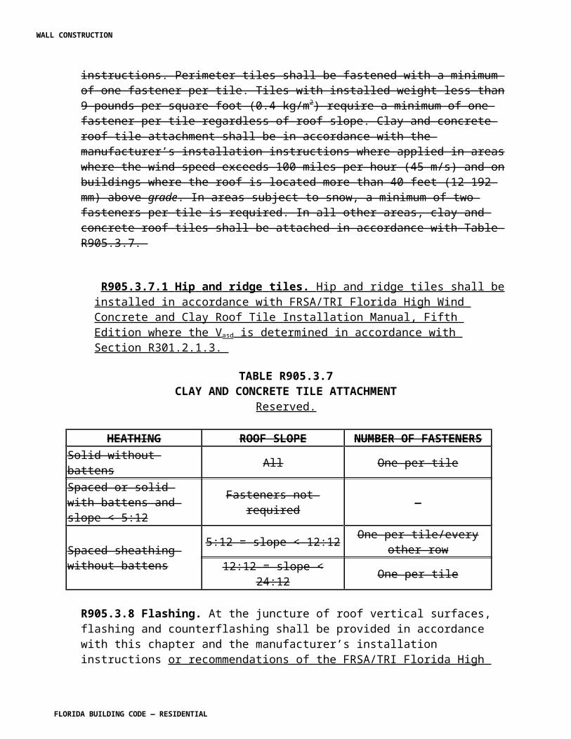
CHAPTER 11 ENERGY EFFICIENCY
Section N101 Energy efficiency. Revise to read as shown:
N1101 Energy efficiency. The provisions of the Florida Building Code, Energy Conservation, shall govern the energy efficiency of residential construction.
[The remaining text of this Chapter is deleted and reserved]
CHAPTER 12 MECHANICAL ADMINISTRATION. [No change]
CHAPTER 13 GENERAL MECHANICAL SYSTEM REQUIREMENTS [No change]
CHAPTER 14, HEATING AND COOLING EQUIPMENT AND APPLIANCES
Section 1411.5 Insulation of refrigerant piping. Change to read as follows:
1411.5 Insulation of refrigerant piping. Piping and fittings for refrigerant vapor (suction) lines shall be insulated with insulation having a thermal resistivity of at least R-3 R-4 and having external surface permeance not exceeding 0.05 perm [2.87 ng/(s . m2 . Pa)] when tested in accordance with ASTM E 96.
(M5756 AS)
CHAPTER 15, EXHAUST SYSTEMS. [No change]
CHAPTER 16, DUCT SYSTEMS
Section M1602.4 Add a section to read as follows:
M1602.4 Balanced Return Air. Restricted return air occurs in buildings when returns are located in central zones and closed interior doors impede air flow to the return grill or when ceiling spaces are used as return plenums and fire walls restrict air movement from one portion of the return plenum to another. Provisions shall be made in both residential and commercial buildings to avoid unbalanced air flows and pressure differentials caused by restricted return air. Pressure differentials across closed doors where returns are centrally located shall be limited to
WALL CONSTRUCTION
FLORIDA BUILDING CODE — RESIDENTIAL
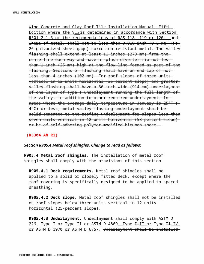
0.01 inch WC (2.5 pascals) or less. Pressure differentials across fire walls in ceiling space plenums shall be limited to 0.01 inch WC (2.5 pascals) by providing air duct pathways or air transfer pathways from the high pressure zone to the low zone.
Exceptions:
1. Transfer ducts may achieve this by increasing the return transfer 11/2 times the cross sectional area (square inches) of the supply duct entering the room or space it is serving and the door having at least an unrestricted 1 inch undercut to achieve proper return air balance.
2. Transfer grilles shall use 50 square inches (of grille area) to 100 cfm (of supply air) for sizing through-the-wall transfer grilles and using an unrestricted 1 inch undercutting of doors to achieve proper return air balance.
3. Habitable rooms only shall be required to meet these requirements for proper balanced return air excluding bathrooms, closets, storage rooms and laundry rooms, except that all supply air into the master suite shall be included.
(M5618 AS) (M5574 AM)
CHAPTER 17, COMBUSTION AIR [No change]
CHAPTER 18, CHIMNEYS AND VENTS [No change]
CHAPTER 19, SPECIAL APPLIANCES, EQUIPMENT AND SYSTEMS [No change]
CHAPTE 20, BOILERS AND WATER HEATERS [No change]
CHAPTER 21, HYDRONIC PIPING [No change]
CHAPTE 22, SPECIAL PIPING AND STORAGE SYSTEMS [No change]
CHAPTER 23, SOLAR ENERGY SYSTEMS
Section M2301.2.2 Roof mounted collectors. Revise section to read as shown:
WALL CONSTRUCTION
FLORIDA BUILDING CODE — RESIDENTIAL
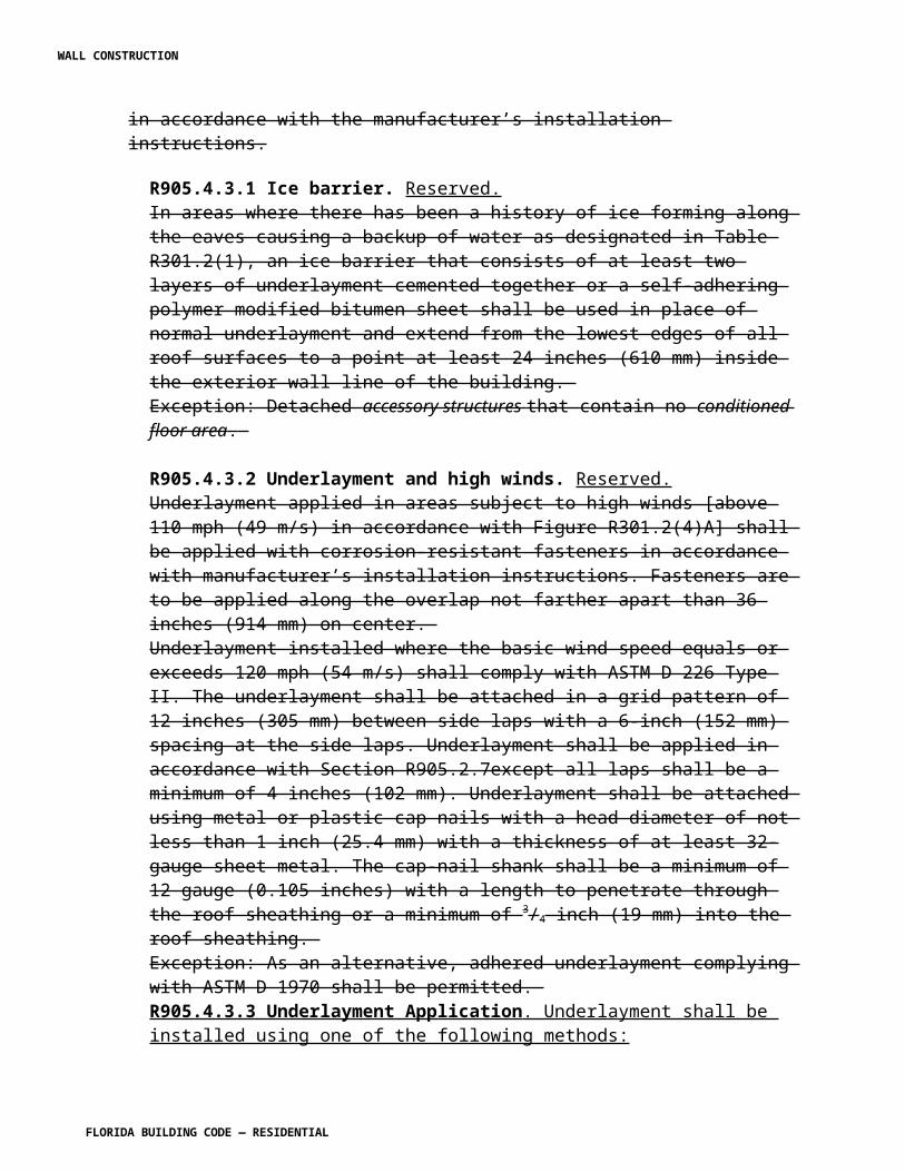
M2301.2.2 Roof-mounted collectors. The roof shall be constructed to support the loads imposed by roof-mounted solar collectors. Roof-mounted solar collectors that serve as a roof covering shall conform to the requirements for roof coverings in Chapter 9 ( the HVHZ shall comply with Chapter 44) of this code. Where mounted on or above the roof coverings, the collectors and supporting structure shall be constructed of noncombustible materials or fire-retardant-treated wood equivalent to that required for the roof construction.
(R4980 AM R1)
Section M2301.2.7 Roof and wall penetrations. Revise section to read as shown:
M2301.2.7 Roof and wall penetrations. Roof and wall penetrations shall be flashed and sealed in accordance with Chapter 9 (the HVHZ shall comply with Chapter 44) of this code to prevent entry of water, rodents and insects.
[M4981 AS]
Section M2302.2.1 Roof-mounted panels and modules. Revise to read as shown:
M2302.2.1 Roof-mounted panels and modules. Where photovoltaic panels and modules are installed on roofs, the roof shall be constructed to support the loads imposed by such modules. Roof-mounted photovoltaic panels and modules that serve as roof covering shall conform to the requirements for roof coverings in Chapter 9 ( the HVHZ shall comply with Chapter 44) . Where mounted on or above the roof coverings, the photovoltaic panels and modules and supporting structure shall be constructed of noncombustible materials or fire-retardant treated wood equivalent to that required for the roof construction.
(R4982 AM R1)
Section M2302.2.2 Roof and wall penetrations. Revise to read as shown:
M2302.2.2 Roof and wall penetrations. Roof and wall penetrations shall be flashed and sealed in accordance with Chapter 9 (the HVHZ shall comply with Chapter 44 ) to prevent entry of water, rodents, and insects.
[M4983 AS]
CHAPTER 24, FUEL GASSection G2412.9 Identification. Revise to read as shown:
G2412.9 (401.9) Identification. Each length of pipe and tubing and each pipe fitting, utilized in a fuel gas system, shall bear the identification of the manufacturer.
Exception : The manufacturer identification for fittings and pipe nipples shall be on each piece or shall be printed on the fitting or nipple packaging or provided documentation.
WALL CONSTRUCTION
FLORIDA BUILDING CODE — RESIDENTIAL
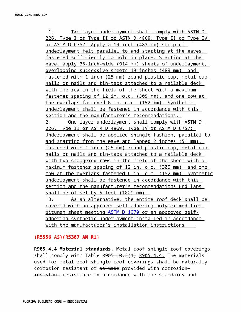
[P5248 AM R1]
Section G2412.10 Third-party testing and certification. Revise to read as shown:
G2412.10· (401.10) Third-party testing and certification. Reserved. All piping, tubing and fittings shall comply with the applicable referenced standards, specifications and performance criteria of this code and shall be identified in accordance with Section 401.9. Piping, tubing and fittings shall either be tested by an approved third-party testing agency or certified by an approved third-party certification agency.
[P5249 AM R1]
CHAPTER 25, PLUMBING ADMINISTRATION [No change]
CHAPTER 26, GENERAL PLUMBING REQUIREMENTS
P2603.3 Breakage and corrosion. Revise to read as shown:
P2603.3 Breakage and corrosion. Pipes passing through concrete or cinder walls and floors, cold-formed steel framing or other corrosive material shall be protected against external corrosion by a protective sheathing or wrapping or other means that will withstand any reaction from lime and acid of concrete, cinder or other corrosive material. Sheathing or wrapping shall allow for movement including expansion and contraction of piping. Minimum wall thickness of material shall be 0.010 inch (0.254 mm).
Exception: Sleeving is not required for installation of CPVC into concrete or similar material
P2603.3.1 Penetration. Add text to read as shown:
P2603.3.1 Penetration. Protective sleeves around piping penetrating concrete slab-on-grade floors shall not be of cellulose-containing materials. If soil treatment is used for subterranean termite protection, the sleeve shall have a maximum wall thickness of 0.010 inch, and be sealed within the slab using a non-corrosive clamping device to eliminate the annular space between the pipe and the sleeve. No termiticides shall be applied inside the sleeve.
CHAPTER 27, PLUMBING FIXTURES. [No change]
CHAPTER 28, WATER HEATERS [No change]
WALL CONSTRUCTION
FLORIDA BUILDING CODE — RESIDENTIAL
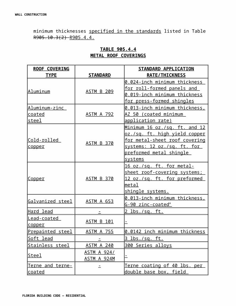
CHAPTER 29, WATER SUPPLY AND DISTRIBUTION [No change]
CHAPTER 30, SANITARY DRAINAGE
Section P3009.1 Scope. Revise to read as shown:
P3009.1 Scope. The provisions of shall govern the materials, design, construction and installation of gray water systems for flushing of water closets and urinals and for subsurface landscape irrigation. See Figures P3009.1(1) and P3009.1(2).
FIGURE P3009.1(1)GRAY WATER RECYCLING SYSTEM FOR FLUSHING WATER CLOSETS AND URINALS
[No change to figure]
Figure P3009.1(2). Delete table and reserve as shown:
FIGURE P3009.1(2)GRAY WATER RECYCLING SYSTEM FOR SUBSURFACE LANDSCAPE IRRIGATION.
Reserved.
Section P3009.2 Installation. Revise to read as shown:
P3009.2 Installation. In addition to the provisions of Section P3009, systems for flushing of water closets and urinals shall comply with Section P3009.13 and systems for subsurface landscape irrigation shall comply with Section P3009.14. Except as provided for in Section P3009, all systems shall comply with the provisions of the other sections of this code.
P3009.3-P3009.13 [Text is unchanged]
Section P3009.14 Landscape irrigation systems. Revise to read as shown. Delete the remainder of Section P3009.14 and show as "Reserved."
P3009.14 Landscape irrigation systems. Reserved. Subsurface landscape irrigation systems shall comply with Sections P3009.14.1 through P3009.14.11
P3009.14.1 Collection reservoir. Reserved. Reservoirs shall be sized to limit the retention time of gray water to a maximum of 24 hours.
WALL CONSTRUCTION
FLORIDA BUILDING CODE — RESIDENTIAL
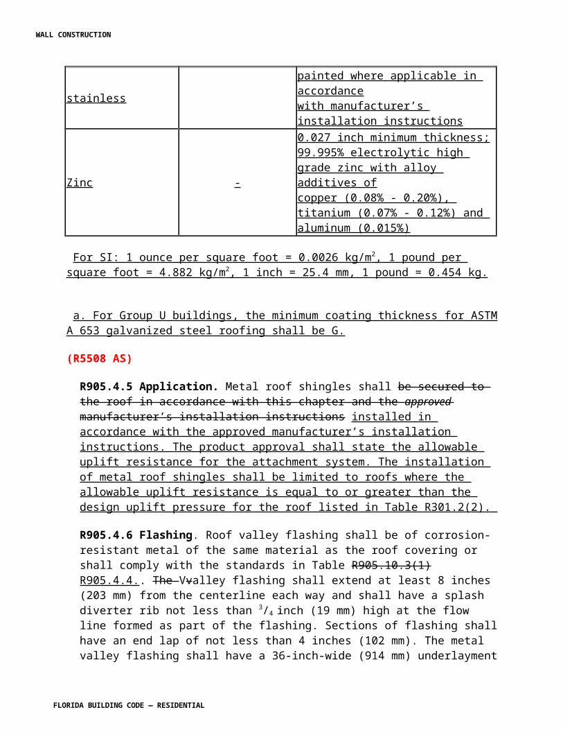
P3009.14.1.1 Identification. Reserved. The reservoir shall be identified as containing nonpotable water.
P3009.14.2 Valves required. Reserved. A check valve and a full-open valve located on the discharge side of the check valve shall be installed on the effluent pipe of the collection reservoir.
P3009.14.3 Makeup water. Reserved. Makeup water shall not be required for subsurface landscape irrigation systems. Where makeup water is provided, the installation shall be in accordance with Section 3009.13.3.
P3009.14.4 Disinfection. Reserved. Disinfection shall not be required for gray water used or subsurface landscape irrigation systems.
P3009.14.5 Coloring. Reserved. Gray water used for subsurface landscape irrigation systems shall not be required to be dyed.
P3009.14.6 Estimating gray water discharge. Reserved. The system shall be sized in accordance with the gallons-per-day-per-occupant number based on the type of fixtures connected to the gray water system. The discharge shall be calculated by the following equation:
C = A × B (Equation 30-1)
where:
A = Number of occupants:
Number of occupants shall be determined by the actual number of occupants, but not less than two occupants for one bedroom and one occupant for each additional bedroom.
B = Estimated flow demands for each occupant:
Residential—25 gallons per day (94.6 lpd) per occupant for showers, bathtubs and lavatories and 15 gallons per day (56.7 lpd) per occupant for clothes washers or laundry trays.
C= Estimated gray water discharge based on the total number of
occupants.
P3009.14.7 Percolation tests. Reserved. The permeability of the soil in the proposed absorption system shall be determined by percolation tests or permeability evaluation.
WALL CONSTRUCTION
FLORIDA BUILDING CODE — RESIDENTIAL
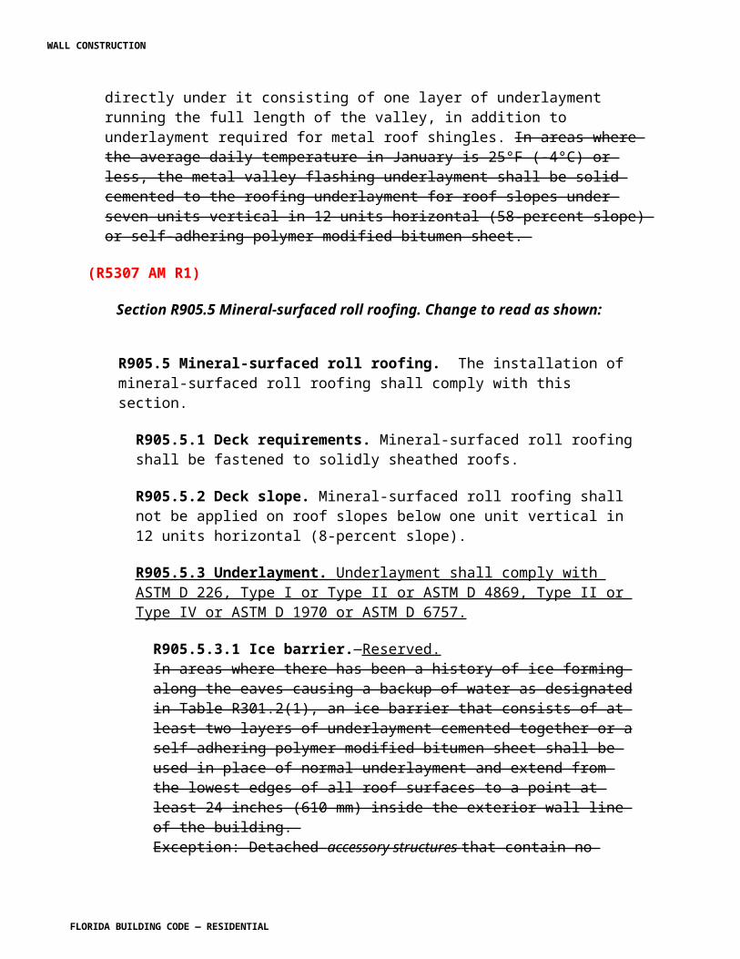
P3009.14.7.1 Percolation tests and procedures. Reserved. At least three percolation tests in each system area shall be conducted. The holes shall be spaced uniformly in relation to the bottom depth of the proposed absorption system. More percolation tests shall be made where necessary, depending on system design.
P3009.14.7.1.1 Percolation test hole. Reserved. The test hole shall be dug or bored. The test hole shall have vertical sides and a horizontal dimension of 4 inches to 8 inches (102 mm to 203 mm). The bottom and sides of the hole shall be scratched with a sharp-pointed instrument to expose the natural soil. All loose material shall be removed from the hole and the bottom shall be covered with 2 inches (51 mm) of gravel or coarse sand.
P3009.14.7.1.2 Test procedure, sandy soils. Reserved. The hole shall be filled with clear water to a minimum of 12 inches (305 mm) above the bottom of the hole for tests in sandy soils. The time for this amount of water to seep away shall be determined, and this procedure shall be repeated if the water from the second filling of the hole seeps away in 10 minutes or less. The test shall proceed as follows: Water shall be added to a point not more than 6 inches (152 mm) above the gravel or coarse sand. Thereupon, from a fixed reference point, water levels shall be measured at 10-minute intervals for a period of 1 hour. Where 6 inches (152 mm) of water seeps away in less than 10 minutes, a shorter interval between measurements shall be used, but in no case shall the water depth exceed 6 inches (152 mm). Where 6 inches (152 mm) of water seeps away in less than 2 minutes, the test shall be stopped and a rate of less than 3 minutes per inch (7.2 s/mm) shall be reported. The final water level drop shall be used to calculate the percolation rate. Soils not meeting the above requirements shall be tested in accordance with Section 3009.14.7.1.3.
P3009.14.7.1.3 Test procedure, other soils. Reserved. The hole shall be filled with clear water, and a minimum water depth of 12 inches (305 mm) shall be maintained above the bottom of the hole for a 4-hour period by refilling whenever necessary or by use of an automatic siphon. Water remaining in the hole after 4 hours shall not be removed. Thereafter, the soil shall be allowed to swell not less than 16 hours or more than 30 hours. Immediately after the soil swelling period, the measurements for determining the percolation rate shall be made as follows: Any soil sloughed into the hole shall be removed and the water level shall be adjusted to 6 inches (152 mm) above the gravel or coarse sand. Thereupon, from a fixed reference point, the water level shall be measured at 30-minute intervals for a period of 4 hours, unless two successive water level drops do not vary by more than 1/16 inch (1.59 mm). At least three water level drops shall be observed and recorded. The hole shall be filled with clear water to a point not more than 6 inches (152 mm) above the gravel or coarse sand whenever it becomes nearly empty. Adjustments of the water level shall not be made during the three measurement periods except to the limits of the last measured water level drop. When the first 6 inches (152 mm) of water seeps away in less than 30 minutes, the time interval between measurements shall be 10 minutes and the test run for 1 hour. The water depth shall not exceed 5 inches (127 mm) at any time during the measurement
WALL CONSTRUCTION
FLORIDA BUILDING CODE — RESIDENTIAL
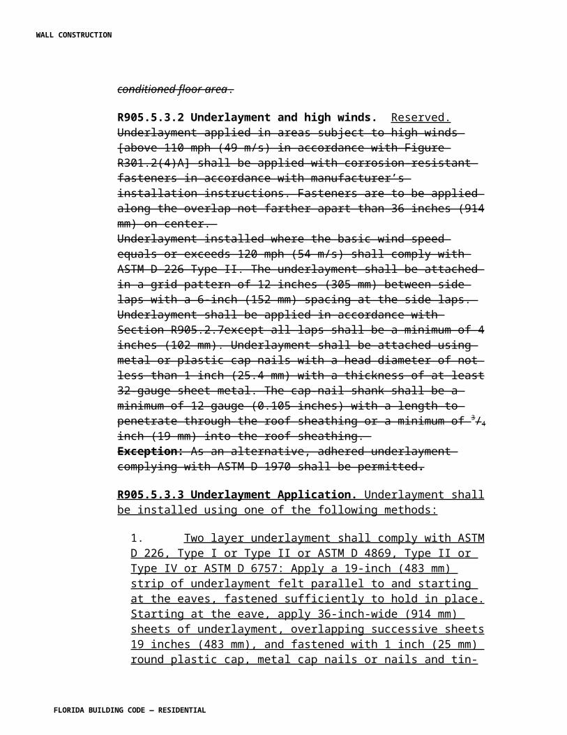
period. The drop that occurs during the final measurement period shall be used in calculating the percolation rate.
P3009.14.7.1.4 Mechanical test equipment. Reserved. Mechanical percolation test equipment shall be of an approved type.
P3009.14.7.2 Permeability evaluation. Reserved. Soil shall be evaluated for estimated percolation based on structure and texture in accordance with accepted soil evaluation practices. Borings shall be made in accordance with Section P3009.14.7.1 for evaluating the soil.
P3009.14.8 Subsurface landscape irrigation site location. Reserved. The surface grade of all soil absorption systems shall be located at a point lower than the surface grade of any water well or reservoir on the same or adjoining lot. Where this is not possible, the site shall be located so that surface water drainage from the site is not directed toward a well or reservoir. The soil absorption system shall be located with a minimum horizontal distance between various elements as indicated in Table P3009.14.8. Private sewage disposal systems in compacted areas, such as parking lots and driveways, are prohibited. Surface water shall be diverted away from any soil absorption site on the same or neighboring lots.
TABLE P3009.14.8LOCATION OF GRAY WATER SYSTEM
Reserved.
ELEMENT
MINIMUM HORIZONTAL DISTANCE
HOLDING TANK
(feet)
IRRIGATION DISPOSAL FIELD
(feet)Buildings 5 2
Property line adjoining private property 5 5
Public water main 10 10
Seepage pits 5 5
Septic tanks 0 5
Streams and lakes 50 50
Water service 5 5
WALL CONSTRUCTION
FLORIDA BUILDING CODE — RESIDENTIAL
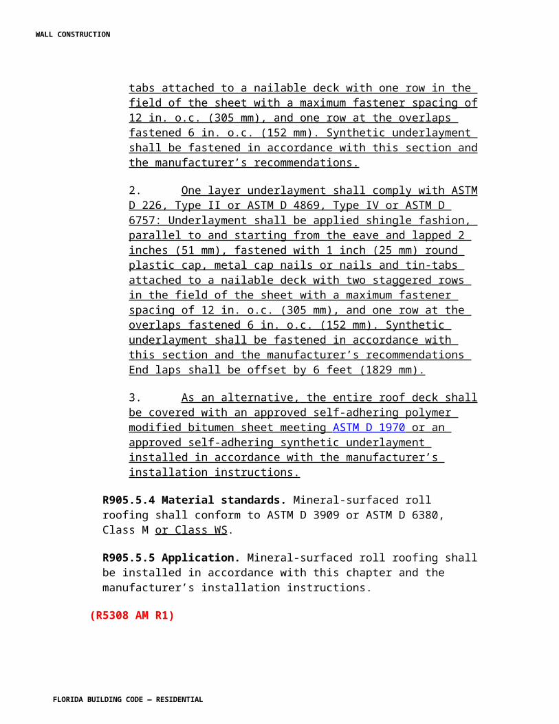
Water wells 50 100
For SI: 1 foot = 304.8 mm.
P3009.14.9 Installation. Reserved. Absorption systems shall be installed in accordance with Sections P3009.14.9.1 through P3009.14.9.5 to provide landscape irrigation without surfacing of gray water.
P3009.14.9.1 Absorption area. Reserved. The total absorption area required shall be computed from the estimated daily gray water discharge and the design-loading rate based on the percolation rate for the site. The required absorption area equals the estimated gray water discharge divided by the design-loading rate from Table P3009.14.9.1.
Table P3009.14.9.1 Design Loading Rate. Delete and reserve as shown:
TABLE P3009.14.9.1DESIGN LOADING RATE
Reserved
PERCOLATION RATE (minutes per inch)
DESIGN LOADING FACTOR (gallons per square foot per day)
0 to less than 10 1.210 to less than 30 0.830 to less than 45 0.72
45 to 60 0.4
For SI: 1 minute per inch = min/25.4 mm,
1 gallon per square foot = 40.7 L/m2.
P3009.14.9.2 Seepage trench excavations. Reserved. Seepage trench excavations shall be a minimum of 1 foot (304 mm) to a maximum of 5 feet (1524 mm) wide. Trench excavations shall be spaced a minimum of 2 feet (610 mm) apart. The soil absorption area of a seepage trench shall be computed by using the bottom of the trench area (width) multiplied by the length of pipe. Individual seepage trenches shall be a maximum of 100 feet (30 480 mm) in developed length.
WALL CONSTRUCTION
FLORIDA BUILDING CODE — RESIDENTIAL
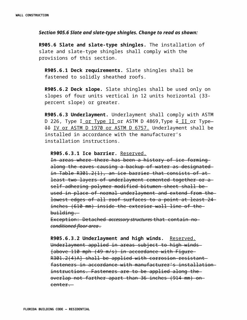
P3009.14.9.3 Seepage bed excavations. Reserved. Seepage bed excavations shall be a minimum of 5 feet (1524 mm) wide and have more than one distribution pipe. The absorption area of a seepage bed shall be computed by using the bottom of the trench area. Distribution piping in a seepage bed shall be uniformly spaced a maximum of 5 feet (1524 mm) and a minimum of 3 feet (914 mm) apart, and a maximum of 3 feet (914 mm) and a minimum of 1 foot (305 mm) from the sidewall or headwall.
P3009.14.9.4 Excavation and construction. Reserved. The bottom of a trench or bed excavation shall be level. Seepage trenches or beds shall not be excavated where the soil is so wet that such material rolled between the hands forms a soil wire. All smeared or compacted soil surfaces in the sidewalls or bottom of seepage trench or bed excavations shall be scarified to the depth of smearing or compaction and the loose material removed. Where rain falls on an open excavation, the soil shall be left until sufficiently dry so a soil wire will not form when soil from the excavation bottom is rolled between the hands. The bottom area shall then be scarified and loose material removed.
P3009.14.9.5 Aggregate and backfill. Reserved. A minimum of 6 inches (152 mm) of aggregate ranging in size from 1/2 inch to 21/2 inches (12.7 mm to 64 mm) shall be laid into the trench below the distribution piping elevation. The aggregate shall be evenly distributed a minimum of 2 inches (51 mm) over the top of the distribution pipe. The aggregate shall be covered with approved synthetic materials or 9 inches (229 mm) of uncompacted marsh hay or straw. Building paper shall not be used to cover the aggregate. A minimum of 9 inches (229 mm) of soil backfill shall be provided above the covering.
P3009.14.10 Distribution piping. Reserved. Distribution piping shall be not less than 3 inches (76 mm) in diameter. Materials shall comply with Table P3009.14.10. The top of the distribution pipe shall be not less than 8 inches (203 mm) below the original surface. The slope of the distribution pipes shall be a minimum of 2 inches (51 mm) and a maximum of 4 inches (102 mm) per 100 feet (30 480 mm).
TABLE P3009.14.10DISTRIBUTION PIPE
Reserved.MATERIAL STANDARD
Polyethylene (PE) plastic pipe ASTM F 405
Polyvinyl chloride (PVC) plastic pipe ASTM D 2729
WALL CONSTRUCTION
FLORIDA BUILDING CODE — RESIDENTIAL
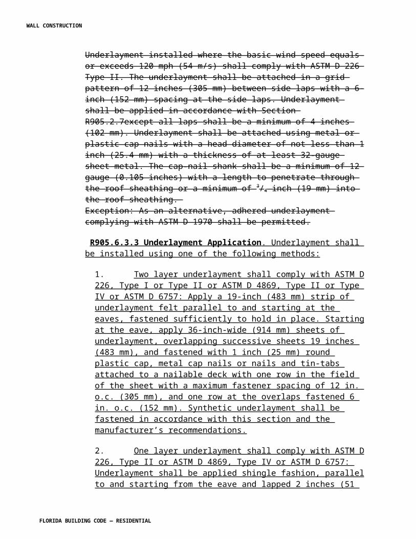
Polyvinyl chloride (PVC) plastic pipe with a 3.5-inch O.D. and solid cellular core or composite wall
ASTM F 1488
P3009.14.11 Joints. Reserved. Joints in distribution pipe shall be made in accordance with Section P3003.
[SP5964 AS]
CHAPTER 31, VENTS [No change]
CHAPTER 32, TRAPS [No change]
CHAPTER 33, STORAGE DRAINAGE [No change]
CHAPTER 34, GENERAL REQUIREMENTS [No change]
CHAPTER 35, ELECTRICAL DEFINITIONS [No change]
CHAPTER 36, SERVICES [No change]
CHAPTER 37, BRANCH CIRCUIT AND FEEDER REQUIREMENTS [No change]
CHAPTER 38, WIRING METHODS [No change]
CHAPTER 39, POWER AND LIGHTING DISTRIBUTION [No change]
CHAPTER 40, DEVICES AND LUMINAIRES [No change]
WALL CONSTRUCTION
FLORIDA BUILDING CODE — RESIDENTIAL
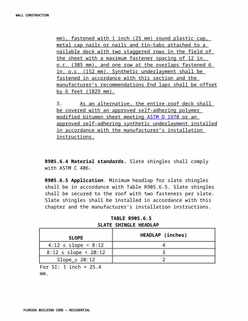
CHAPTER 41, APPLIANCE INSTALLATION [No change]
CHAPTER 42, SWIMMING POOLS
Revise Chapter 42 to read as follows:
SECTION R4201PRIVATE SWIMMING POOLS
R4201.1 Definitions, general.
R4201.1.1 Tense, gender and number. For the purpose of this code, certain abbreviations, terms, phrases, words, and their derivatives shall be construed as set forth in this section. Words used in the present tense include the future. Words in the masculine gender include the feminine and neuter. Words in the feminine and neuter gender include the masculine. The singular number includes the plural and the plural number includes the singular.
R4201.1.2 Words not defined. Words not defined herein shall have the meanings stated in the Florida Building Code, Building; Florida Building Code, Mechanical; Florida Building Code, Plumbing; Florida Building Code, Fuel Gas; or Florida Fire Prevention Code. Words not defined in the Florida Building Code shall have the meanings stated in the Webster's Third New International Dictionary of the English Language Unabridged.
R4201.2 Definitions. ABOVEGROUND/ONGROUND POOL. See "Swimming Pool." ADMINISTRATIVE AUTHORITY. The individual official, board, department or agency established and authorized by a state, county, city or other political subdivision created by law to administer and enforce the provisions of the swimming pool code as adopted or amended. APPROVED. Accepted or acceptable under an applicable specification stated or cited in this code, or accepted as suitable for the proposed use under procedures and power of the administrative authority. APPROVED SAFETY COVER. A manually or power-applied safety pool cover that meets all of the performance standards of the ASTM International in compliance with ASTM F 1346. APPROVED TESTING AGENCY. An organization primarily established for the purpose of testing to approved standards and approved by the administrative authority. BACKWASH PIPING. See "Filter waste discharge piping."
WALL CONSTRUCTION
FLORIDA BUILDING CODE — RESIDENTIAL
BARRIER. A fence, dwelling wall or nondwelling wall or any combination thereof which completely surrounds the swimming pool and obstructs access to the swimming pool, especially access from the residence or from the yard outside the barrier. BODY FEED. Filter aid fed into a diatomite-type filter throughout the filtering cycle. CARTRIDGE FILTER. A filter using cartridge type filter elements. CHEMICAL PIPING. Piping which conveys concentrated chemical solutions from a feeding apparatus to the circulation piping. CIRCULATION PIPING SYSTEM. Piping between the pool structure and the mechanical equipment. Usually includes suction piping, face piping and return piping. COMBINATION VALVE. A multipart valve intended to perform more than one function. DESIGN HEAD. Total head requirement of the circulation system at the design rate of flow. DIATOMITE (DIATOMACEOUS EARTH). A type of filter aid. DIATOMITE TYPE FILTER. A filter designed to be used with filter aid. DIRECT ACCESS FROM THE HOME. Means any opening which discharges into the "perimeter" of the pool or any opening in an exterior dwelling wall, or interior wall (for indoor pools) which faces the pool. EXIT ALARM. A device that makes audible, continuous alarm sounds when any door or window which permits access from the residence to any pool that is without an intervening enclosure is opened or left ajar. FACE PIPING. Piping, with all valves and fittings, which is used to connect the filter system together as a unit. FILTER. Any apparatus by which water is clarified. FILTER AID. A nonpermanent type of filter medium or aid such as diatomite, alum, etc. FILTER CARTRIDGE. A disposable or renewable filter element which generally employs no filter aid. FILTER ELEMENT. That part of a filter which retains the filter medium. FILTER MEDIUM. Fine material which entraps the suspended particles and removes them from the water. FILTER RATE. Average rate of flow per square foot of filter area.
WALL CONSTRUCTION
FLORIDA BUILDING CODE — RESIDENTIAL
FILTER ROCK. Specially graded rock and gravel used to support filter sand. FILTER SAND. A specially graded type of permanent filter medium. FILTER SEPTUM. That part of the filter element in a diatomite type filter upon which a cake of diatomite or other nonpermanent filter aid may be deposited. FILTER WASTE DISCHARGE PIPING. Piping that conducts waste water from a filter to a drainage system. Connection to drainage system is made through an air gap or other approved methods. FRESH WATER. Those waters having a specific conductivity less than a solution containing 6,000 ppm of sodium chloride. HIGH RATE SAND FILTER. A sand filter designed for flows in excess of 5 gpm per square feet. HOT TUB. See "Swimming pool." INGROUND POOL. See "Swimming pool." INLET FITTING. Fitting or fixture through which circulated water enters the pool. MAIN SUCTION OUTLET. Outlet at the deep portion of the pool through which the main flow of water leaves the pool when being drained or circulated. MEDICALLY FRAIL ELDERLY PERSON. Means any person who is at least 65 years of age and has a medical problem that affects balance, vision, or judgment, including but not limited to a heart condition, diabetes, or Alzheimer's disease or any related disorder. MESH SAFETY BARRIER. A combination of materials, including fabric, posts, and other hardware to form a barrier around a swimming pool. POOL. See "Swimming pool." POOL DEPTHS. The distance between the floor of pool and the maximum operating water level. POOL PERIMETER. A pool perimeter is defined by the limits of the pool deck, its surrounding area including yard area on same property, and any dwelling or nondwelling wall or any combination thereof which completely surrounds the pool. POOL PLUMBING. All chemical, circulation, filter waste discharge piping, deck drainage and water filling system.
WALL CONSTRUCTION
FLORIDA BUILDING CODE — RESIDENTIAL
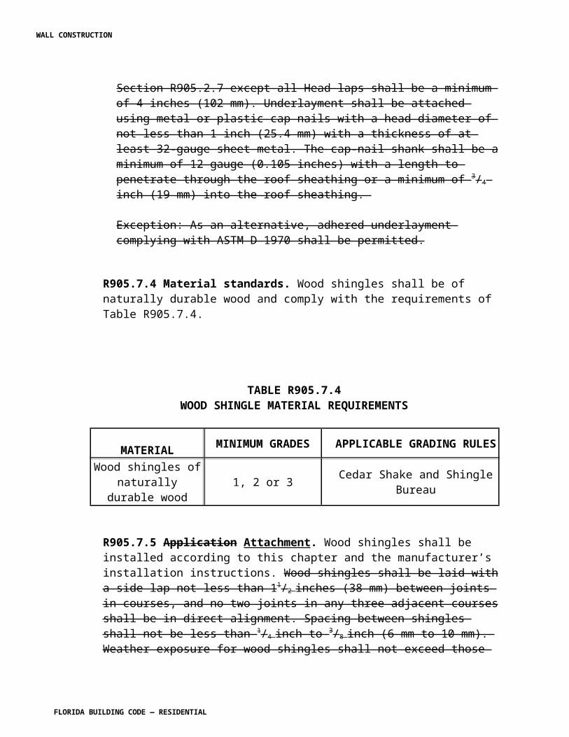
PORTABLE POOL. A prefabricated pool which may be erected at the point of intended use and which may be subsequently disassembled and reerected at a new location. Generally installed on the surface of the ground and without excavation. PRECOAT. In a diatomite-type filter, the initial coating or filter aid placed on the filter septum at the start of the filter cycle. RAPID SAND FILTER. A filter designed to be used with sand as the filter medium and for flows not to exceed 5 gpm per square feet. RECEPTOR. An approved plumbing fixture or device of such material, shape and capacity as to adequately receive the discharge from indirect waste piping, so constructed and located as to be readily cleaned. RESIDENTIAL. Means situated on the premises of a detached one-family or two-family dwelling or a one-family townhouse not more than three stories high. RETURN PIPING. That portion of the circulation piping which extends from the outlet side of the filters to the pool. SALINE WATER. Those waters having a specific conductivity in excess of a solution containing 6,000 ppm of sodium chloride. SEPARATION TANK. A device used to clarify filter rinse or waste water. Sometimes called a reclamation tank. SKIM FILTER. A surface skimmer combined with a vacuum diatomite filter. SPA, NONPORTABLE. See "Swimming pool." SPA, PORTABLE. Nonpermanent structure intended for recreational bathing, in which all controls and water heating and water circulating equipment are an integral part of the product and which is cord-connected and not permanently electrically wired. SUCTION PIPING. That portion of the circulation piping located between the pool structure and the inlet side of the pump and usually includes main outlet piping, skimmer piping, vacuum piping and surge tank piping. SURFACE SKIMMER. A device generally located in the pool wall which skims the pool surface by drawing pool water over a self adjusting weir. SWIMMING POOL, PRIVATE. Any structure, located in a residential area, that is intended for swimming or recreational bathing and contains water over 24 inches (610 mm) deep including but not limited to inground, aboveground, and onground swimming pools, hot tubs, and nonportable spas.
WALL CONSTRUCTION
FLORIDA BUILDING CODE — RESIDENTIAL
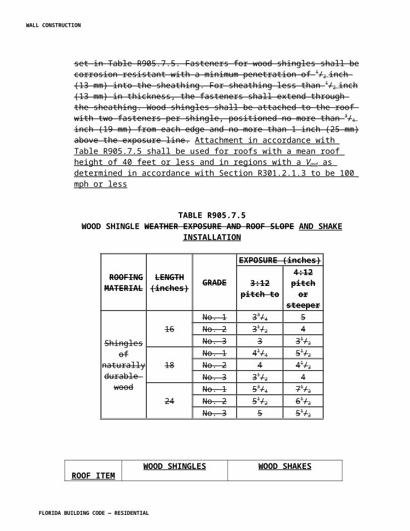
SWIMMING POOL, INDOOR. A swimming pool which is totally contained within a structure and surrounded on all four sides by walls of said structure. SWIMMING POOL, OUTDOOR. Any swimming pool which is not an indoor pool. SWIMMING POOL, PUBLIC. A water-tight structure of concrete, masonry, fiberglass, stainless steel or plastic which is located either indoors or outdoors, used for bathing or swimming by humans, and filled with a filtered and disinfected water supply, together with buildings, appurtenances and equipment used in connection therewith. A public swimming pool or public pool shall mean a conventional pool, spa-type pool, wading pool, special purpose pool or water recreation attraction, to which admission may be gained with or without payment of a fee and includes, pools operated by or serving camps, churches, cities, counties, day care centers, group home facilities for eight or more clients, health spas, institutions, parks, state agencies, schools, subdivisions; or the cooperative living-type projects of five or more living units, such as apartments, boarding houses, hotels, mobile home parks, motels, recreational vehicle parks and townhouses. SWIMMING POOL, RESIDENTIAL. See "Swimming pool, private." TURNOVER TIME. The time in hours required for the circulation system to filter and recirculate a volume of water equal to the pool volume. VACUUM FITTING. A fitting in the pool which is used as a convenient outlet for connecting the underwater suction cleaning equipment. VACUUM PIPING. The piping from the suction side of a pump connected to a vacuum fitting located at the pool and below the water level. WASTE PIPING. See "Filter waste discharge piping." WIDTH AND/OR LENGTH. Actual water dimension taken from wall to wall at the maximum operating water level. YOUNG CHILD. Means any person under the age of six years. R4201.3 Mechanical requirements. Unless otherwise specified in this code, all piping, equipment and materials used in the process piping system of swimming pools that are built in place shall conform to the Florida Building Code, Plumbing. R4201.4 Approvals.
R4201.4.1 Compliance. All materials, piping, valves, equipment or appliances entering into the construction of swimming pools or portions thereof shall be of a type complying with this code or of a type recommended and approved by a nationally recognized testing agency or conforming to other recognized standards acceptable to the administrative authority.
WALL CONSTRUCTION
FLORIDA BUILDING CODE — RESIDENTIAL
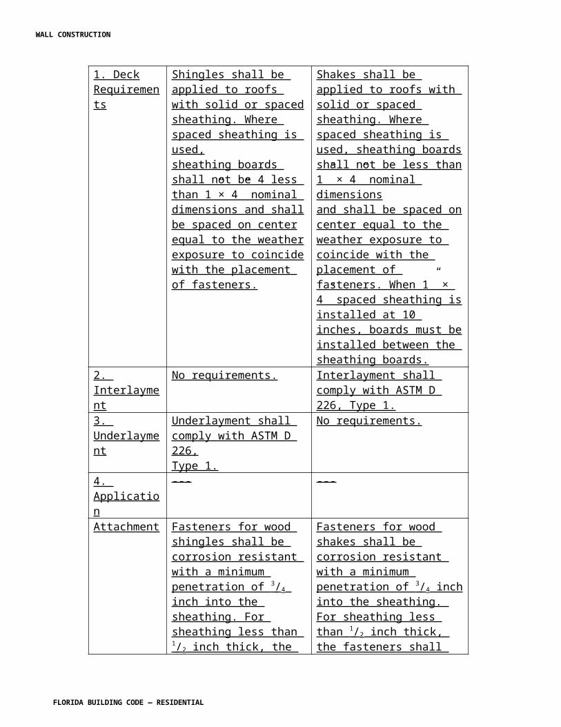
R4201.4.2 Items not covered. For any items not specifically covered in these requirements, the administrative authority is hereby authorized to require that all equipment, materials, methods of construction and design features shall be proven to function adequately, effectively and without excessive maintenance and operational difficulties.
R4201.4.2.1. Flood hazard areas. Pools installed in flood hazard areas established in Section R322 shall comply with Section R322.2.4 (A Zones) or R322.3.3.1 in coastal high-hazard areas (V Zones).
[SP5294 AS]
R4201.4.3 Applicant responsibility. It shall be the responsibility of the applicant to provide such data, tests or other adequate proof that the device, material or product will satisfactorily perform the function for which it is intended, before such item shall be approved or accepted for tests.
R4201.5 Alternate materials and methods of construction.
R4201.5.1 Approval and authorization. The provisions of this code are not intended to prevent the use of any alternate material, method of construction, appliance or equipment, provided any such alternate has been first approved and its use authorized by the administrative authority.
R4201.5.2 Required tests. When there is insufficient evidence to substantiate claims for alternates, the administrative authority may require tests, as proof of compliance, to be made by an approved agency at the expense of the applicant.
R4201.6 Engineering design.
R4201.6.1 Conformance standard. Design, construction and workmanship shall be in conformity with the requirements of ANSI/NSPI 3; ANSI/NSPI 4; ANSI/NSPA 5; ANSI/NSPI 6; and ANSI/APSP 7.
R4201.6.2 Required equipment. Every swimming pool shall be equipped complete with approved mechanical equipment consisting of filter, pump, piping valves and component parts.
Exception: Pools with a supply of fresh water equivalent to the volume of the pool in the specified turnover time will be allowed.
R4201.6.3 Water velocity. Pool piping shall be designed so the water velocity will not exceed 10 feet per second (3048 mm/s) for pressure piping and 8 feet per second (2438 mm/s) for suction piping, except that the water velocity shall not exceed 8 feet per second (2438 mm/s) in copper tubing. Main suction outlet velocity must comply with ANSI/APSP 7.
Exception: Jet inlet fittings shall not be deemed subject to this requirement.
WALL CONSTRUCTION
FLORIDA BUILDING CODE — RESIDENTIAL
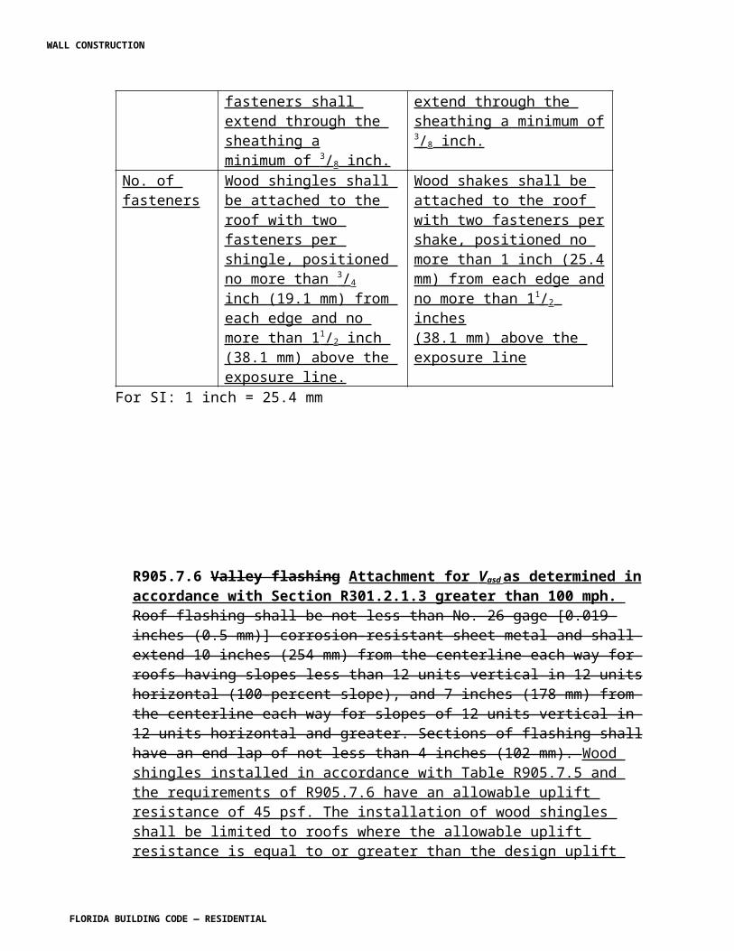
R4201.6.4 Piping to heater. Water flow through the heater, any bypass plumbing installed, any back-siphoning protection, and the use of heat sinks shall be done in accordance with the manufacturer's recommendations.
R4201.6.5 Piping installation. All piping materials shall be installed in strict accordance with the manufacturer's installation standards.
Exception: Primer and glue on exposed aboveground piping not required to be colored.
R4201.6.6 Entrapment protection. Entrapment protection for suction outlets shall be installed in accordance with requirements of ANSI/APSP 7.
R4201.7 Pumps.
R4201.7.1 Strainer. Pool circulating pumps shall be equipped on the inlet side with an approved type hair and lint strainer when used with a pressure filter.
R4201.7.2 Installation. Pumps shall be installed in accordance with manufacturer recommendations.
R4201.7.3 Capacity. Pumps shall have design capacity at the following heads:
1. Pressure Diatomaceous Earth-At least 60 feet (18 288 mm).2. Vacuum Diatomaceous Earth-20-inch (508 mm) vacuum on the suction side and 40-foot (12 192 mm) total head.3. Rapid Sand-At least 45 feet (13 716 mm).4. High Rate Sand-At least 60-feet (18 288 mm).
R4201.7.4 Materials. Pump impellers, shafts, wear rings and other working parts shall be of corrosion-resistant materials.
R4201.8 Valves.
R4201.8.1 General. Valves shall be made of materials that are approved in the Florida Building Code, Plumbing. Valves located under concrete slabs shall be set in a pit having a least dimension of five pipe diameters with a minimum of at least 10 inches (254 mm) and fitted with a suitable cover. All valves shall be located where they will be readily accessible for maintenance and removal.
R4201.8.2 Full-way (gate) valves. Full-way valves shall be installed to insure proper functioning of the filtration and piping system. When the pump is located below the overflow rim of the pool, a valve shall be installed on the discharge outlet and the suction line.
R4201.8.3 Check valves. Where check valves are installed they shall be of the swing, spring or vertical check patterns.
R4201.8.4 Combination valves. Combination valves shall be installed per manufacturer's installation instructions.
WALL CONSTRUCTION
FLORIDA BUILDING CODE — RESIDENTIAL
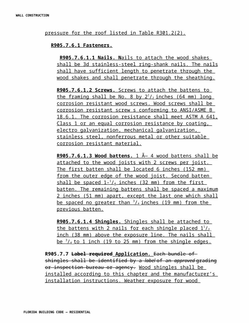
R4201.9 Water supply. Unless an approved type of filling system is installed, any water supply which in the judgment of the administrative authority may be used to fill the pool, shall be equipped with backflow protection. No over the rim fill spout shall be accepted unless located under a diving board, or properly guarded. R4201.10 Waste water disposal.
R4201.10.1 Connection limitations. Direct or indirect connections shall not be made between any storm drain, sewer, drainage system, seepage pit underground leaching pit, or subsoil drainage line, and any line connected to a swimming pool unless approved by the administrative authority.
R4201.10.2 Disposal through public sewer. When the waste water from a swimming pool is to be disposed of through a public sewer, a 3-inch (76 mm) P-trap shall be installed on the lower terminus of the building drain and the tall piece from the trap shall extend a minimum of 3-inches (76 mm) above finished grade and below finished floor grade. This trap need not be vented. The connection between the filter waste discharge piping and the P-trap shall be made by means of an indirect connection.
R4201.10.3 Deviations. Plans and specifications for any deviation from the above manner of installation shall first be approved by the administrative authority before any portion of any such system is installed. When waste water disposal is to seepage pit installation, it shall be installed in accordance with the approval granted by the administrative authority.
R4201.11 Separation tank. A separation tank of an approved type may be used in lieu of the aforementioned means of waste water disposal when connected as a reclamation system. R4201.12 Tests.
R4201.12.1 Pressure test. All pool piping shall be tested and proved tight to the satisfaction of the administrative authority, under a static water or air pressure test of not less than 35 pounds per square inch (psi) (241 kPa) for 15 minutes.
Exception: Circulating pumps need not be tested as required in this section.
R4201.12.2 Drain and waste piping. All drain and waste piping shall be tested by filling with water to the point of overflow and all joints shall be tight.
R4201.13 Drain piping.
R4101.13.1 Slope to discharge. Drain piping serving gravity overflow gutter drains and deck drains shall be installed to provide continuous grade to point of discharge.
R4201.13.2 Joints and connections. Joints and connections shall be made as required by the Florida Building Code, Plumbing.
R4201.14 Water heating equipment.
WALL CONSTRUCTION
FLORIDA BUILDING CODE — RESIDENTIAL
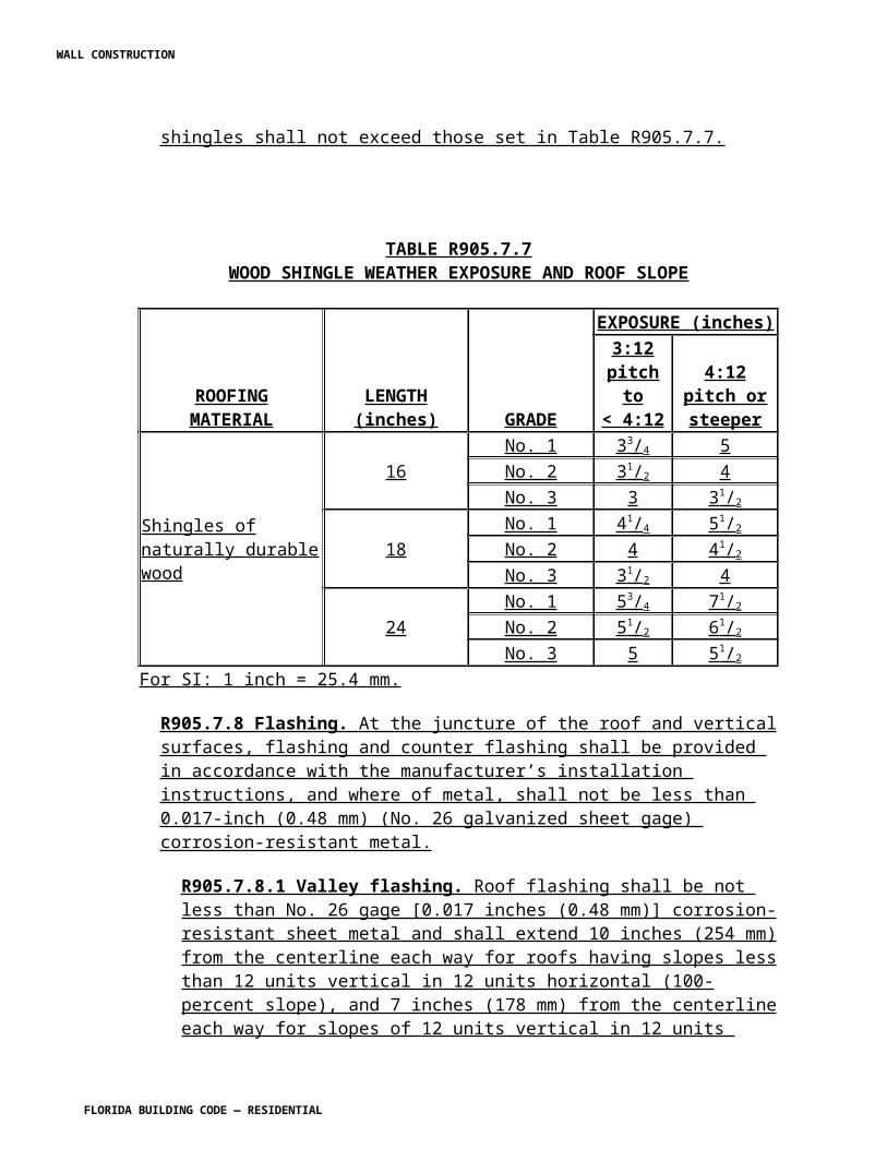
R4201.14.1 Labels. Swimming pool water heating equipment shall conform to the design, construction and installation requirements in accordance with accepted engineering practices and shall bear the label of a recognized testing agency, and shall include a consideration of combustion air, venting and gas supply requirements for water heaters.
R4201.14.2 Water retention. If a heater is not equipped or designed for an approved permanent bypass or antisiphon device, an approved permanent bypass or antisiphon device shall be installed to provide a positive means of retaining water in the heater when the pump is not in operation.
R4201.14.3 Pit drainage. When the heater is installed in a pit, the pit shall be provided with approved drainage facilities.
R4201.14.4 Connections. All water heating equipment shall be installed with flanges or union connection adjacent to the heater.
R4201.14.5 Relief valve. When water heating equipment which is installed in a closed system has a valve between the appliance and the pool, a pressure relief valve shall be installed on the discharge side of the water heating equipment. For units up to and including 200,000 Btu/hour input, the relief valve shall be rated by the American Gas Association.
R4201.15 Gas piping. Gas piping shall comply with the Florida Building Code, Fuel Gas. R4201.16 Electrical. Electrical wiring and equipment shall comply with Chapter 27 of the Florida Building Code. R4201.17 Residential swimming barrier requirement. Residential swimming pools shall comply with Sections R4201.17.1 through R4201.17.3.
Exception: A swimming pool with an approved safety pool cover complying with ASTM F 1346.
R4202.17.1 Outdoor swimming pools. Outdoor swimming pools shall be provided with a barrier complying with R4201.17.1.1 through R4201.17.1.14.
R4201.17.1.1 The top of the barrier shall be at least 48 inches (1219 mm) above grade measured on the side of the barrier which faces away from the swimming pool. The maximum vertical clearance between grade and the bottom of the barrier shall be 2 inches (51 mm) measured on the side of the barrier which faces away from the swimming pool. Where the top of the pool structure is above grade the barrier may be at ground level or mounted on top of the pool structure. Where the barrier is mounted on top of the pool structure, the maximum vertical clearance between the top of the pool structure and the bottom of the barrier shall be 4 inches (102 mm).
R4201.17.1.2 The barrier may not have any gaps, openings, indentations, protrusions, or structural components that could allow a young child to crawl under, squeeze through, or
WALL CONSTRUCTION
FLORIDA BUILDING CODE — RESIDENTIAL
climb over the barrier as herein described below. One end of a removable child barrier shall not be removable without the aid of tools. Openings in any barrier shall not allow passage of a 4-inch-diameter (102 mm) sphere.
R4201.17.1.3 Solid barriers which do not have openings shall not contain indentations or protrusions except for normal construction tolerances and tooled masonry joints.
R4201.17.1.4 Where the barrier is composed of horizontal and vertical members and the distance between the tops of the horizontal members is less than 45 inches (1143 mm), the horizontal members shall be located on the swimming pool side of the fence. Spacing
between vertical members shall not exceed 13/4 inches (44 mm) in width. Where there
are decorative cutouts within vertical members, spacing within the cutouts shall not
exceed 13/4 inches (44 mm) in width.
R4201.17.1.5 Where the barrier is composed of horizontal and vertical members and the distance between the tops of the horizontal members is 45 inches (1143 mm) or more, spacing between vertical members shall not exceed 4 inches (102 mm). Where there are decorative cutouts within vertical members, spacing within the cutouts shall not exceed
13/4 inches (44 mm) in width.
R4201.17.1.6 Maximum mesh size for chain link fences shall be a 21/4 inch square (57
mm) unless the fence is provided with slats fastened at the top or bottom which reduce
the openings to no more than 13/4 inches (44 mm).
R4201.17.1.7 Where the barrier is composed of diagonal members, the maximum
opening formed by the diagonal members shall be no more than 13/4 inches (44 mm).
R4201.17.1.8 Access gates, when provided, shall be self-closing and shall comply with the requirements of Sections R4201.17.1.1 through R4201.17.1.7 and shall be equipped with a self-latching locking device located on the pool side of the gate. Where the device release is located no less than 54 inches (1372 mm) from the bottom of the gate, the device release mechanism may be located on either side of the gate and so placed that it cannot be reached by a young child over the top or through any opening or gap from the outside. Gates that provide access to the swimming pool must open outward away from
the pool. The gates and barrier shall have no opening greater than 1/2 inch (12.7 mm)
within 18 inches (457 mm) of the release mechanism.
R4201.17.1.9 Where a wall of a dwelling serves as part of the barrier, one of the following shall apply:
WALL CONSTRUCTION
FLORIDA BUILDING CODE — RESIDENTIAL
1. All doors and windows providing direct access from the home to the pool shall be
equipped with an exit alarm complying with UL 2017 that has a minimum sound pressure rating of 85 dB A at 10 feet (3048 mm). Any deactivation switch shall be located at least 54 inches (1372 mm) above the threshold of the access. Separate alarms are not required for each door or window if sensors wired to a central alarm sound when contact is broken at any opening.
Exceptions:
a. Screened or protected windows having a bottom sill height of 48 inches
(1219 mm) or more measured from the interior finished floor at the pool access level.
b. Windows facing the pool on floor above the first story.
c. Screened or protected pass-through kitchen windows 42 inches (1067 mm) or higher with a counter beneath.
2. All doors providing direct access from the home to the pool must be equipped
with a self-closing, self-latching device with positive mechanical latching/locking installed a minimum of 54 inches (1372 mm) above the threshold, which is approved by the authority having jurisdiction.
R4201.17.1.10 Where an aboveground pool structure is used as a barrier or where the barrier is mounted on top of the pool structure, and the means of access is a ladder or steps, the ladder or steps either shall be capable of being secured, locked or removed to prevent access, or the ladder or steps shall be surrounded by a barrier which meets the requirements of Sections R4201.17.1.1 through R4201.17.1.9 and Sections R4201.17.1.12 through R4201.17.1.14. When the ladder or steps are secured, locked or removed, any opening created shall not allow the passage of a 4-inch-diameter (102 mm) sphere.
R4201.17.1.11 Standard screen enclosures which meet the requirements of Section R4201.17 may be utilized as part of or all of the "barrier" and shall be considered a "nondwelling" wall. Removable child barriers shall have one end of the barrier nonremovable without the aid of tools.
R4201.17.1.12 The barrier must be placed around the perimeter of the pool and must be separate from any fence, wall, or other enclosure surrounding the yard unless the fence, wall, or other enclosure or portion thereof is situated on the perimeter of the pool, is being used as part of the barrier, and meets the barrier requirements of this section.
R4201.17.1.13 Removable child barriers must be placed sufficiently away from the water's edge to prevent a young child or medically frail elderly person who may manage to penetrate the barrier from immediately falling into the water. Sufficiently away from the water's edge shall mean no less than 20 inches (508 mm) from the barrier to the
WALL CONSTRUCTION
FLORIDA BUILDING CODE — RESIDENTIAL
water's edge. Dwelling or nondwelling walls including screen enclosures, when used as part or all of the "barrier" and meeting the other barrier requirements, may be as close to the water's edge as permitted by this code.
R4201.17.1.14 A wall of a dwelling may serve as part of the barrier if it does not contain any door or window that opens to provide direct access from the home to the swimming pool.
R4201.17.1.14.1 Adjacent waterways. Permanent natural or permanent man-made features such as bulkheads, canals, lakes, navigable waterways, etc., adjacent to a public or private swimming pool or spa may be permitted as a barrier when approved by the authority having jurisdiction. When evaluating such barrier features, the authority may perform on-site inspections and review evidence such as surveys, aerial photographs, water management agency standards and specifications, and any other similar documentation to verify, at a minimum, the following:
1. The barrier feature is not subject to natural changes, deviations, or
alterations and is capable of providing an equivalent level of protection as that provided by the code.
2. The barrier feature clearly impedes, prohibits or restricts access to the
swimming pool or spa.
R4201.17.1.15 A mesh safety barrier meeting the requirements of Section R4201.17 and the following minimum requirements shall be considered a barrier as defined in this section:
1. Individual component vertical support posts shall be capable of resisting a
minimum of 52 pounds (229 N) of horizontal force prior to breakage when measured at a 36-inch (914 mm) height above grade. Vertical posts of the child mesh safety barrier shall extend a minimum of 3 inches (76 mm) below deck level and shall be spaced no greater than 36 inches (914 mm) apart.
2. The mesh utilized in the barrier shall have a minimum tensile strength
according to ASTM D 5034 of 100 lbf., and a minimum ball burst strength according to ASTM D 3787 of 150 lbf. The mesh shall not be capable of
deformation such that a 1/4-inch (6.4 mm) round object could pass
through the mesh.
The mesh shall receive a descriptive performance rating of no less than "trace discoloration" or "slight discoloration" when tested according to ASTM G 53 (Weatherability, 1,200 hours).
WALL CONSTRUCTION
FLORIDA BUILDING CODE — RESIDENTIAL
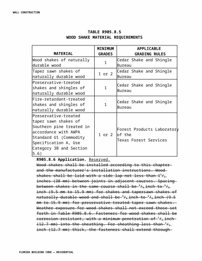
3. When using a molding strip to attach the mesh to the vertical posts, this
strip shall contain, at a minimum, #8 by 1/2-inch (12.7 mm) screws with a
minimum of two screws at the top and two at the bottom with the remaining screws spaced a maximum of 6 inches (152 mm) apart on center.
4. Patio deck sleeves (vertical post receptacles) placed inside the patio
surface shall be of a nonconductive material.
5. A latching device shall attach each barrier section at a height no lower than 45 inches (11 613 mm) above grade. Common latching devices that include, but are not limited to, devices that provide the security equal to or greater than that of a hook and eye type latch incorporating a spring actuated retaining lever (commonly referred to as a safety gate hook).
6. The bottom of the child mesh safety barrier shall not be more than 1 inch
(25 mm) above the deck or installed surface (grade).
R4201.17.2 Indoor swimming pools. All walls surrounding indoor swimming pools shall comply with Section R4201.17.1.9.
R4201.17.3 Prohibited locations. A barrier may not be located in a way that allows any permanent structure, equipment, or window that opens to provide access from the home to the swimming pool.
R4201.18 Ladders and steps. All pools whether public or private shall be provided with a ladder or steps in the shallow end where water depth exceeds 24 inches (610 mm). In private pools where water depth exceeds 5 feet (1524 mm), there shall be ladders, stairs or underwater benches/swimouts in the deep end. Where manufactured diving equipment is to be used, benches or swimouts shall be recessed or located in a corner.
Exception: In private pools having more than one shallow end, only one set of steps are required. A bench, swim-out or ladder may be used at all additional shallow ends in lieu of an additional set of steps.
R4201.19 Final inspection. Final electrical, and barrier code, inspection shall be completed prior to filling the pool with water.
Exception: Vinyl liner and fiberglass pools are required to be filled with water upon installation.
R4201.20 Filters. Components shall have sufficient capacity to provide a complete turnover of pool water in 12 hours or less.
R4201.20.1 Sand filters.
WALL CONSTRUCTION
FLORIDA BUILDING CODE — RESIDENTIAL
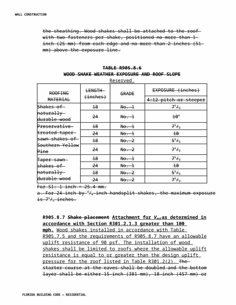
R4201.20.1.1 Approved types. Rapid sand filters (flow up to 5 gpm per square foot) shall be constructed in accordance with approved standards. Where high rate sand filters (flow in excess of 5 gpm per square foot) are used, they shall be of an approved type. The circulation system and backwash piping shall be adequate for proper backwashing of said filter and shall provide backwash flow rates of at least 12 gpm per square foot or rapid sand filters or 15 gpm per square foot or high rate sand filters.
R4201.20.1.2 Instructions. Every filter system shall be provided with written operating instructions.
R4201.20.1.3 Filter system equipment. On pressure type filters, a means shall be provided to permit the release of internal pressure. A filter incorporating an automatic internal air release as its principal means of air release shall have lids which provide a slow and safe release of pressure as part of its design. A separation tank used in conjunction with a filter tank shall have as part of its design a manual means of air release or a lid which provides a slow and safe release of pressure as it is opened.
R4201.20.2 Diatomite type filters.
R4201.20.2.1 Design. Diatomite-type filters shall be designed for operation under either pressure or vacuum. The design capacity for both pressure and vacuum filters shall not exceed 2 gpm per square foot of effective filter area.
R4201.20.2.2 Filter aid. Provision shall be made to introduce filter aid into the filter in such a way as to evenly precoat the filter septum.
R4201.21 Pool fittings.
R4201.21.1 Approved type. Pool fittings shall be of an approved type and design as to be appropriate for the specific application.
R4201.21.2 Skimmers. Approved surface skimmers are required and shall be installed in strict accordance with the manufacturer's installation instructions. Skimmers shall be installed on the basis of one per 800 square feet (74 m2) of surface area or fraction thereof, and shall be designed for a flow rate of at least 25 gallons per minute (gpm) (1.6 L/s) per skimmer.
R4201.21.3 Main outlet. An approved main outlet, when provided, shall be located on a wall or floor at or near the deepest point in the pool for emptying or circulation, or both, of the water in the pool.
R4201.21.4 Hydrostatic relief device. In areas of anticipated water table an approved hydrostatic relief device shall be installed.
Exception: Plastic liner pools (where there is no structural bottom to the pool).
WALL CONSTRUCTION
FLORIDA BUILDING CODE — RESIDENTIAL
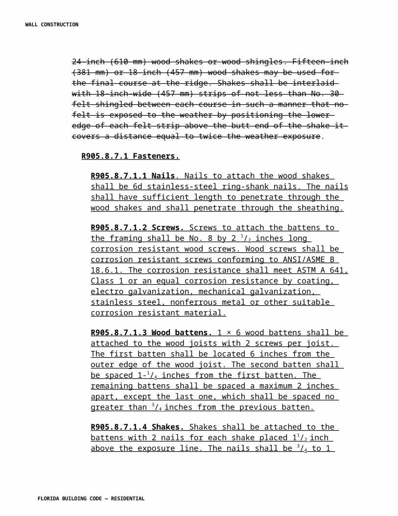
R4201.21.5 Inlet fittings. Approved manufactured inlet fittings for the return of recirculated pool water shall be provided on the basis of at least one per 300 square feet (28 m2) of surface area. Such inlet fittings shall be designed and constructed to insure an adequate seal to the pool structure and shall incorporate a convenient means of sealing for pressure testing of the pool circulation piping. Where more than one inlet is required, the shortest distance between any two required inlets shall be at least 10 feet (3048 mm).
R4201.22 Equipment foundations and enclosures. All pool motors and equipment shall be installed in compliance with the manufacturers recommendations. All heating and electrical equipment, unless approved for outdoor installation, shall be adequately protected against the weather or installed within a building. R4201.23 Accessibility and clearances. Equipment shall be so installed as to provide ready accessibility for cleaning, operating, maintenance and servicing.
(SW5443 AS) CHAPTER 43 CLASS 2 REMOTE-CONTROL, SIGNALING AND POWER-LIMITED CIRCUITS [No change]
CHAPTER 44 HIGH-VELOCITY HURRICANE ZONES REFERENCED STANDARDS
Section R4401. Change to read as follows:
SECTION R4401HIGH-VELOCITY HURRICANE ZONES —
EXTERIOR WALL COVERING R4401.1 Refer to Chapter 14 of the Florida Building Code, Building. R4401.2 Asphalt shingles. Asphalt shingles shall be applied only to solid wood sheathing and shall be in tin-capped and spot-stuck, as set forth in Section R4402. R4401.3 Roll slate or felt. Roll slate or felt shall be applied only to solid wood sheathing and shall be secured by nailing, as set forth in Section R4402. R4401.4 Metal shingles. Metal shingles shall be applied only to solid wood sheathing and shall be secured as set forth in Section R4402. R4401.5 Steel shingles. Steel siding shall be designed and applied as set forth in Section R4408. R4401.6 Aluminum siding. Aluminum siding shall be designed and applied as set forth in Section R4406.
WALL CONSTRUCTION
FLORIDA BUILDING CODE — RESIDENTIAL
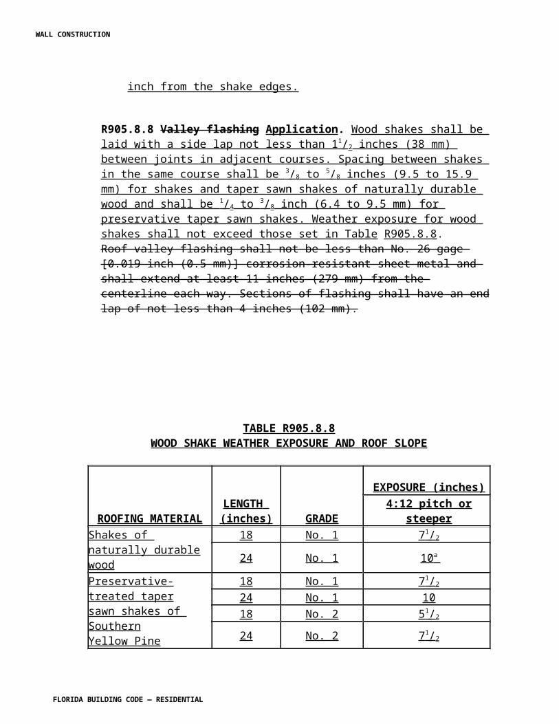
R4401.7 Veneers. Masonry veneers shall be applied as set forth in Section R4407. R4401.9 Other materials. Any cladding materials or assembly not addressed in this code shall be classified by the building official as the one it most nearly resembles, and shall comply with the requirements for loading and fire resistance herein required for such materials and assemblies.
[Mod R5008] AS
Section R4402. Change to read as follows:
SECTION R4402HIGH-VELOCITY HURRICANE ZONES —
ROOF ASSEMBLIES AND ROOFTOP STRUCTURES R4402.1. General Refer to Chapter 15 of the Florida Building Code, Building . R4402.1.1 Scope. The provisions of this section shall set forth minimum requirements for the installation of roofing components, roofing systems, roofing assemblies and the waterproofing thereof. R4402.1.2 Application. These High-velocity Hurricane Zone roofing requirements with associated roofing application standards (RAS) and testing application standards (TAS) are solely to be implemented in areas of high basic wind speeds, and where the jurisdiction having authority has adopted their use. R4402.1.2.1 All roofing components, roofing systems and roofing assemblies for construction regulated by this code shall comply with this chapter. All roofing components, roofing systems and roofing assemblies shall have a valid and current, referred to as product approval hereinafter. In the event that the manufacturers published literature or instructions are in conflict with those of the product approval, the product approval shall prevail. Where items specifically and expressly addressed in this section are in conflict with the product approval, the provisions of this section shall prevail. R4402.1.2.2 Innovative products and/or systems outside those currently recognized under this chapter may have a product approval issued based on performance testing; in such case(s) the conditions set in the product approval shall prevail. R4402.1.2.3 For roofing systems to be installed on a specific building or structure, where an existing product approval may not be applied, such roofing system may be granted a onetime approval by the authority having jurisdiction, provided the applicant demonstrates, by testing and/or rational analysis that such roofing system complies with the provision of this code. R4402.1.2.4 Where a product approval does not address a detail for a specific job condition, the permit applicant may propose to the building official an alternate detail to address the specific need of the job. The building official may accept such proposal if it can be demonstrated that the provisions of this code will be met.
WALL CONSTRUCTION
FLORIDA BUILDING CODE — RESIDENTIAL
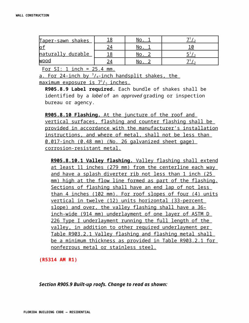
R4402.1.2.5 Workmanship standards. All roofing work shall be performed by a qualified contractor licensed to perform roofing, in compliance with the tolerances, quality and methods of construction established herein or set forth in the standards adopted by these high-velocity hurricane zone requirements. Roofing assemblies detailed in product approvals shall be installed in strict compliance with the method of application set forth in such product approval or, if not part of the product approval, in compliance with manufacturer's published application instructions, or as approved by the building official. (Aesthetic issues not affecting the performance of the roof are not part of this section.) R4402.1.2.5.1 Appearance. If the architectural appearance is to be preserved from below, an alternate method of attachment complying with the wind load requirements of Section R4403 may be proposed unless otherwise addressed in Section R4402. The alternative attachment shall be prepared, signed and sealed by a Florida-registered architect or a Florida-registered engineer, which architect or engineer shall be proficient in structural design. R4402.1.3 Permits outside these High-Velocity Hurricane Zone requirements shall comply with Section 105 of the Florida Building Code, Building . Permits within high wind areas shall be required for all work in connection with the application, repair or maintenance of any roofing component or any roofing assembly and/or any of its components except as otherwise permitted in Section 105 of the Florida Building Code, Building . R4402.1.3.1 All new roofing construction, including recovering and reroofing, repair and maintenance shall have a uniform roofing permit application, as established by the authority having jurisdiction, completed and executed by a licensed contractor. R4402.1.3.2 The uniform roofing permit shall include calculations per Section R4403 of this code, unless the roofing assembly is less than the height/pressure threshold allowed in the applicable protocols herein. 4402.1.3.3 Reserved. R4402.1.3.4 Attachments to the uniform roofing permit application shall include two copies of each of the following documents: properly executed OWNERS NOTIFICATION FOR ROOFING CONSIDERATIONS herein; the fire directory listing pages product approval cover sheet, product approval specific system description, product approval specific system limitation, product approval general limitations, and applicable detail drawings; the municipal permit application; other components approvals; and any other additional data reasonably required by the authority having jurisdiction needed to determine the integrity of the roofing system. R4402.1.4.1 All roofing work for which a permit is required shall be inspected by the building official. One or more inspections may be performed at the same time at the request of the roofing contractor or when feasible. Lack of roofing contractor's personnel at the job site, in and of itself, shall not be cause to fail the inspection. Certain roofing inspections shall be performed during specific phases of the applications as noted below:
WALL CONSTRUCTION
FLORIDA BUILDING CODE — RESIDENTIAL
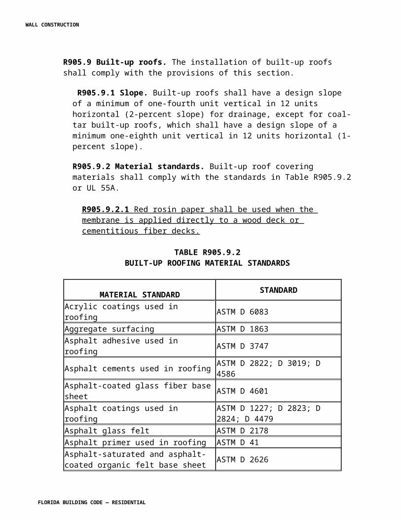
R4402.1.4.2 For discontinuous roofing systems (as defined herein or Chapter 2): R4402.1.4.2.1 During or after application of the base sheet, anchor sheet or underlayment of any roofing system. R4402.1.4.2.2 During the installation of the cap sheet. R4402.1.4.2.3 During the installation of any prepared roof covering, such as shingles, tiles, slates, shakes, and similar. R4402.1.4.2.4 Upon completion of all adhesive-set and mortar-set tile systems, and prior to the final inspection, a field verification and static uplift test, in compliance with TAS 106 shall be required to confirm tile adhesion. This test may be required by the building official for mechanically attached tile systems. All results of this test shall be submitted to the building official. R4402.1.4.3 For continuous roofing systems (as defined in herein or Chapter 2): R4402.1.4.3.1 During application of any roofing system prior to the full concealment of the adhesion/attachment process to the roof deck or to the existing roofing assembly. R4402.1.4.3.2 In cases where a roof area is less than 1,500 square feet (139 m2), and when the building official is not able to perform any of the above requested inspection in a timely manner, the building official may authorize to continue with the work and may require that satisfactory evidence be provided to show that the covered work was performed in compliance with this code. R4402.1.4.3.3 After all roofing work has been completed; a final inspection shall be performed by the building official.
SECTION R4402.2HIGH-VELOCITY HURRICANE ZONES —
DEFINITIONS R4402.2.1 Definitions. For definitions outside Section R4402 and accompanied RAS and TAS, see Chapter 2. For the purposes of Section R4402, accompanying RAS, TAS and roofing products product approval, roofing terms shall be defined in compliance with ASTM D 1079, unless otherwise defined below. The definitions listed below shall take preference. Other terms used herein shall be defined as set forth in Chapter 2 of this code. AIR PERMEABLE ROOFING SYSTEM. A roofing system consisting of a prepared roof covering over an approved underlayment on a sloped roof. The components within the prepared roof covering are discontinuously laid and small, with unsealed side and head laps. Air permeable roofing systems shall be applied over sheathed decks with either mechanical
WALL CONSTRUCTION
FLORIDA BUILDING CODE — RESIDENTIAL
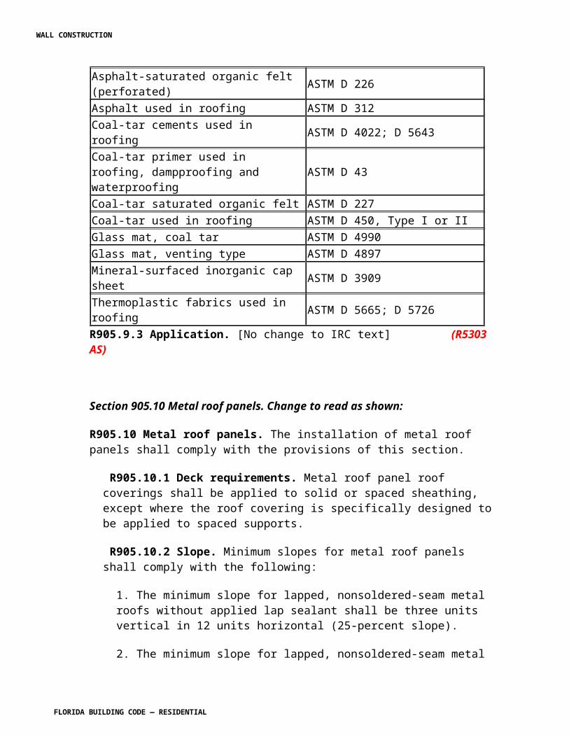
attachment or a mortar/adhesive bond. Any roofing system with sealed side or head laps shall not be defined as an air permeable roofing system. The authority having jurisdiction may require testing in compliance with TAS 116, to determine whether a roofing system is air permeable. ANCHOR SHEET. A roofing felt mechanically attached to a nailable deck with approved fasteners to which insulation is then installed in a solid mopping of asphalt. The roofing membrane is then installed to the insulation in the usual manner. ARCHITECTURAL METAL PANEL. Water shedding (hydrokinetic) roof panel fastened to a roof deck. ASTM (ASTM International). A scientific and technical organization that is responsible for the development of standards on characteristics and performance of materials, products, systems, as adopted for the high-velocity hurricane zone. NET FREE VENTILATING AREA (NFVA). The gross area of the smallest plane area of the ventilating device reduced by the percentage of physical obstruction to the plane area. BASE SHEET. The bottom or first ply of a roofing assembly over which subsequent roofing plies are applied. A base sheet may be designed for mechanical attachment, full or partial adhesion to the substrate. BUILDING INTEGRATED PHOTOVOLTAIC ROOFING. A roofing product consisting of an electricity generating photovoltaic component integrated into a roof covering. CLASS A ROOFING ASSEMBLY. A roofing assembly that, in combination with the roof slope, has been classified by an approved testing agency, with a listing and follow-up service, as "Class A" in compliance with ASTM E 108 or UL 790. CLASS B ROOFING ASSEMBLY. A roofing assembly that, in combination with the roof slope, has been classified by an approved testing agency, with a listing and follow-up service, as "Class B" in compliance with ASTM E 108 or UL 790. CLASS C ROOFING ASSEMBLY. A roofing assembly that, in combination with the roof slope, has been classified by an approved testing agency, with a listing and follow-up service, as "Class C" in compliance with ASTM E 108 or UL 790. CONTINUOUS ROOFING SYSTEM. An impervious roof covering, composed from a single or multiple layers, forming a homogenous membrane over the entire roof surface, applied to either a flat or pitched roof surfaces. CORROSION RESISTANT. Any component that passes appendix of FMRC's Test Standard 4470, as modified, and set forth in TAS 114. COUNTER BATTENS. Vertical wood strips installed on sloped roofs over which horizontal battens are secured. The primary roof covering is attached or secured to these horizontal battens.
WALL CONSTRUCTION
FLORIDA BUILDING CODE — RESIDENTIAL
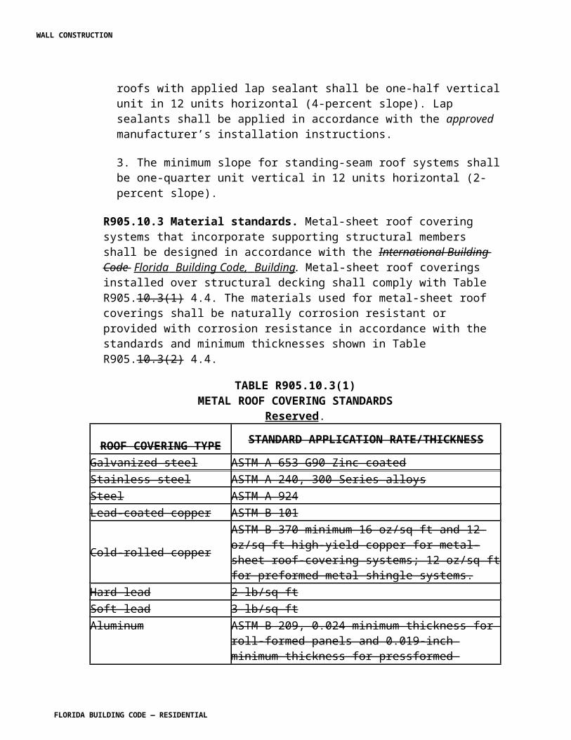
COUNTERFLASHING. Formed metal or elastomeric sheeting secured on or into a wall, curb, pipe, roof-top unit or other surface to cover and protect the upper edge of a base flashing and its associated fasteners. DISCONTINUOUS ROOFING SYSTEM. A roofing system with unsealed overlapping components, where the combined roofing system has openings at the point of overlap, applied to a sloped surface with a pitch of 2:12, or greater. Discontinuous roofing systems include asphalt shingles; concrete, clay or metal tile; wood shingles or shakes; and cement fiber roofing systems. DRY-IN. The process of applying the first layer of felt in a roofing system. FM APPROVALS. A research and testing organization that is responsible for examination and testing of construction and other products. FASTENER WITHDRAWAL RESISTANCE TEST. A static pullout test of mechanical fasteners, which are used to anchor any roofing component, to determine the force required to withdraw a fastener from the substrate. Testing shall be in compliance with the test procedure detailed in TAS 105. FIRE-RESISTANT ROOF COVERING. Any Class A, Class B or Class C roofing system applied to the appropriate deck type within the specified slope of the listed classification. FLASHING. The roofing component used to seal roofing systems, where the system is interrupted or terminated. LAP. See NRCA Manual fourth edition. METAL PROFILE. Including but not limited to eave and gable drip, gravel stop, raised edge systems and fascia systems. All composite and nonmetallic flashing materials shall have a Product Approval. MINIMUM CHARACTERISTIC RESISTANCE FORCE. A force or pressure which is representative of data from withdrawal resistance testing; static uplift testing; and/or wind uplift testing after the data has been statistically analyzed to a 95 percent level of precision. METAL ROOF PANEL. An interlocking metal sheet having an installed weather exposure equal or greater than three square feet per sheet. METAL ROOF SHINGLE. An interlocking metal sheet having an installed weather exposure less than three square feet per sheet. MOMENT. A quantity that represents the affect of a force applied at a particular point in relation to a specific point or axis.
WALL CONSTRUCTION
FLORIDA BUILDING CODE — RESIDENTIAL
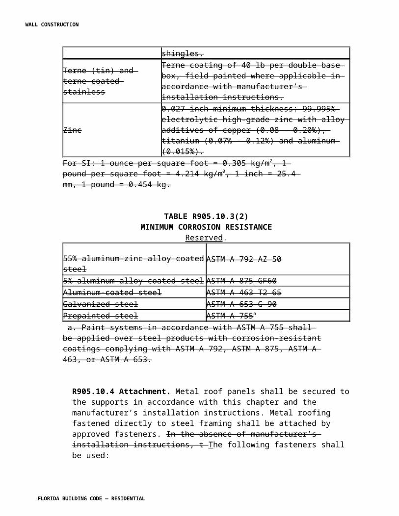
NRCA. The NRCA Roofing and Waterproofing Manual , fifth edition, as published by the National Roofing Contractors Association. PREPARED ROOF COVERING. Any manufactured or processed roof covering designed for use as the top layer of a discontinuous roofing system applied to a sloped roof. RAS. Roofing Application Standards. RECOVERING. The process of covering an existing roofing assembly with a new roofing system or a prepared roofing system. REPAIR. The work of corrective procedures by replacing or altering an existing roofing component or system to eliminate water intrusion REROOFING. The process of recovering or replacing an existing roofing system, either in its entirety or in existing sections. RIDGE VENT. A ventilator located within 18 inches (457 mm) of the ridge that allows the escape of warm and/or moist air from the attic area or rafter cavity. ROOFING ACCESSORY. A type of roofing product as described in Section R4402.6.6 of this code. ROOFING ASSEMBLY. An assembly of interacting roofing components [includes the roof deck, vapor retarder (if present), insulation, and roof covering]. ROOFING COATINGS, ADHESIVES AND MASTICS. Any and all liquid materials applied to the roofing membrane layer to enhance ultraviolet light resistance; increase resistance to fire; increase reflectivity of the roofing assembly; or, in some way, enhance the performance of the roofing assembly. Roofing coatings, adhesives or mastics shall not contain asbestos materials. ROOF COVERING. An assembly of multiple field-applied components or a single component designed to weatherproof a building's top surface. A roof covering may be a roofing assembly or form a portion thereof. ROOFING COMPONENT. A roofing product that is incorporated into various roofing assemblies. ROOF DECK. Solid or spaced sheathing to which the roofing or waterproofing system is applied. ROOFING MAINTENANCE. Is the work of extending the longevity of a roofing system through preventative care, such as refilling pitch pans, applying coatings, re-graveling, resurfacing and re-caulking.
WALL CONSTRUCTION
FLORIDA BUILDING CODE — RESIDENTIAL
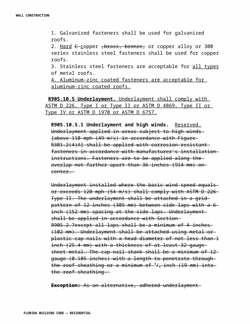
ROOF SECTION. A separation or division of a roof area by existing expansion joints, parapet walls, flashing (excluding valleys), difference of elevation (excluding hips and ridges), roof type or legal description; not including the roof area required for a proper tie-off with an existing system. ROOFING SYSTEM. A system of interacting roofing components, generally consisting of membrane or primary roof covering and insulation (not including the roof deck) designed to weatherproof, and sometimes to improve, the building's thermal resistance. HIGH ROOF TILE PROFILE. Those tiles having a rise-to-width ratio greater than 0.20 LOW ROOF TILE PROFILE. Those tiles having a rise-to-width ratio less or equal than 0.20; except those tiles meeting the flat profile definition. FLAT ROOF TILE PROFILE. Those tiles with less than 1/2-inch (12.7 mm) rise. STRUCTURAL METAL PANEL. Roof covering intended to be self supporting between structural members (see Sections R4406.1.8.2 and R4408.9.4). TAS. Testing Application Standard. UNDERLAYMENT. One or more water shedding layers applied to a sloped roof prior to the application of a prepared roof covering. The primary purpose of an underlayment is defined as a water shedding layer to function in combination with a prepared roof covering. WOOD SHAKES. Tapered or straight pieces of red cedar, or other wood types, of widths ranging from 3 inches to 14 inches (76 mm to 356 mm) ranging in lengths from 18 inches to 32 inches (437 mm to 819 mm) applied to a sloped roof, in conjunction with an approved underlayment, forming a discontinuous prepared roof system. WOOD SHINGLES. Tapered pieces of red cedar, or other wood types, sawn on both faces, of widths ranging from 3 inches to 14 inches (76 mm to 356 mm) and lengths of 16 inches, 18 inches, and 24 inches (406 mm to 610 mm) applied to a sloped roof forming a discontinuous prepared roof system.
SECTION R4402.3HIGH-VELOCITY HURRICANE ZONES —
WEATHER PROTECTION R4402.3.1 General. Roof decks shall be covered with roof coverings secured to the building or structure in accordance with the provisions of this section. Roof coverings shall be designed, installed and maintained in accordance with this code and the manufacturer's installation instructions such that the roof covering shall serve to protect the building or structure. All roof coverings, roof systems and roof assemblies shall be designed and installed to resist the wind load requirements of Section R4403 of this code.
WALL CONSTRUCTION
FLORIDA BUILDING CODE — RESIDENTIAL
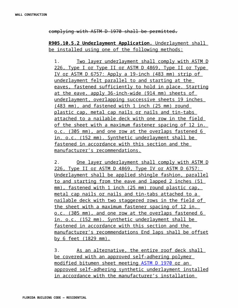
R4402.3.2.2 Membrane flashings. All membrane flashing shall be installed according to the roof assembly manufacturer's published literature and in accordance with the provisions set forth in RAS 111. R4402.3.2.3 Metal flashings and terminations. Metal flashing and terminations shall be of the material and thickness described in Section R4402.6.6 and RAS 111 of this code, and shall be designed and installed in accordance with RAS 111 R4402.3.2.3.1 Such felts shall be embedded in hot bitumen or an approved adhesive. R4402.3.2.3.2 Metal surfaces shall be primed with an ASTM D 41 or ASTM D 43 primer, as appropriate and allowed to dry prior to receiving hot bitumen or cold adhesive. R4402.3.2.4 Metal counterflashing. Metal counterflashing shall be of the material and thickness described in Sections R4402.6.6 and RAS 111 of this code, and shall be installed in accordance with RAS 111. R4402.3.2.4.1 Metal counterflashing shall be built into walls, set in reglets or applied as stucco type and shall be turned down over base flashing not less than 3 inches (76 mm). R4402.3.2.4.2 Metal counterflashing shall be side lapped a minimum of 4 inches (102 mm). R4402.3.2.4.3 Metal counterflashing, where set in reglets or surface-mounted, shall be waterproofed, in accordance with applicable application standards. R4402.3.2.4.4 Where metal counterflashing is used as the means of sealing (such as a vented system) it shall be set in an approved sealant, sealed with an approved adhesive on the top flange and all joints shall be sealed with an approved sealant and lapped a minimum of 4 inches (102 mm). R4402.3.2.5 Roof penetration flashing. R4402.3.2.5.1 All pipes shall be flashed with approved lead sleeve-type, pitch pans or other approved methods detailed in the roofing system assembly product approval. Lead flashing shall not be less than 2.5 pound per square foot (12.2 kg/m2). Flanges shall be a minimum of 4 inches (102 mm). R4402.3.2.5.2 Other roof penetrations shall be suitably flashed with curbs, collars, pitch pans, in compliance with RAS 111 or an approved method, in compliance with the roofing system assembly Product Approval. R4402.3.2.5.3 No roof penetration shall be located in roof valleys.
WALL CONSTRUCTION
FLORIDA BUILDING CODE — RESIDENTIAL
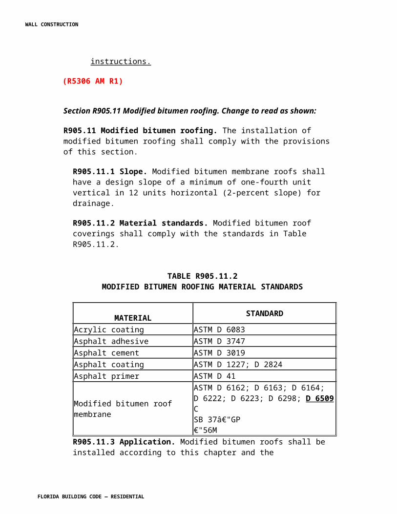
R4402.3.3 Coping. Copings shall be designed and installed to resist the wind load requirements of Section R4403 of this code, and shall be in accordance with the provisions set forth in RAS 111. R4402.3.4 Roof drainage. Unless roofs are sloped to drain over roof edges, roof drains shall be installed at each low point of the roof. Where required for roof drainage, scuppers shall be placed level with the roof surface in a wall or parapet. The scupper shall be located as determined by the roof slope and contributing roof area. Scuppers shall be sized in accordance with the provisions contained in ASCE 7, Section 8 with commentary and shall comply with Section R4403.6. R4402.3.4.1.1 Gutters shall be in compliance with RAS 111. R4402.3.4.2 Overflow drains and scuppers. Where roof drains are required, overflow drains or overflow scuppers sized in accordance with Florida Building Code, Plumbing shall be installed with the inlet flow line located not less than 2 inches (51 mm) or more than 4 inches (102 mm) above the low point of the finished roofing surface, excluding sumps. Overflow scuppers shall be a minimum of 4 inches (102 mm) in any dimension and shall be placed in walls or parapets and shall be located as close as practical to required vertical leaders, conductors or downspouts. Overflow drains and scuppers shall also comply with the Florida Building Code, Plumbing , and Section R4403.6 of this code. R4402.3.4.2.1 When overflow scuppers and roof drains are installed, they shall be lined with approved metal or other approved materials set forth in the roofing system assembly Product Approval. R4402.3.4.2.2 When recovering, reroofing or repairing an existing roof, the existing number of scuppers and/or roof drains shall not be reduced, unless a new drainage system is designed by an architect or engineer, in compliance with the provisions of this code. R4402.3.4.3 Sizing and discharge. Roof drains, gutters, conductors and leaders shall be sized and discharge in accordance with the Florida Building Code, Plumbing .
SECTION R4402.4HIGH-VELOCITY HURRICANE ZONES —
PERFORMANCE REQUIREMENTS R4402.4.1 General. All roof assemblies, roof coverings and roof systems shall have Product Approval, and shall meet the following minimum requirements. R4402.4.1.1 All continuous roofing assemblies shall be tested in compliance with FMRC Test Standards 4470 and/or 4471 (for metal roofing), as modified for the purposes of this code and set forth in TAS 114. Only those components listed within the roofing assembly Product Approval shall be approved for use with the roof covering. Roofing assemblies shall be acceptable for use in this code's jurisdiction providing they are in compliance with the fire classification required for the structure to which the roofing assembly is to be installed.
WALL CONSTRUCTION
FLORIDA BUILDING CODE — RESIDENTIAL
R4402.4.1.2 All fastening devices and fastening assemblies used for insulation, anchor sheet or roof coverings shall be tested in compliance with Section R4402.12 of this code. R4402.4.1.3 All roofing assemblies shall be tested by a testing laboratory certified. R4402.4.1.4 All roofing membranes and components shall be tested in compliance with the physical property test requirements detailed in TAS 110. R4402.4.1.5 No loose laid ballasted or non-ballasted system shall be allowed. R4402.4.2 Guidelines for roofing applications. R4402.4.2.1 Decks. All roofing systems and prepared roof coverings shall be installed over solid decks, unless otherwise specifically allowed in other sections of this code. R4202.4.2.2 Minimum slope. All roofing assemblies must be installed in compliance with the slope requirements specified in the product approval, in compliance with Table R4402.4.2
TABLE R4402.4.2MINIMUM SLOPE
SYSTEM TYPE SLOPEFibrous Cement Shingles 4:12Metal Panels 2:12ArchitecturalMetal Shingles 4:12Mortar or Adhesive Tile 2:12Mechanically Fastened TileAsphalt Shingles
4:12
Laminated 2:123-Tab 2:12Quarry Slate 3-1/2:12Wood 2:12Shakes 4:12Shingles 3-1/2:12
R4402.4.2.3.2 All eaves shall provide a firm nailable substrate for secure attachment of perimeter edge metal in compliance with RAS 111. R4402.4.2.3.3 Perimeter edge metal shall be fastened with nails or fasteners fabricated from similar or compatible material. The nails or fasteners shall be as set forth in the roofing assembly product approval.
WALL CONSTRUCTION
FLORIDA BUILDING CODE — RESIDENTIAL
R4402.4.2.4 Impact resistance. Roof coverings installed on low slope roofs in accordance with R4402.8 shall resist impact damage based on the results of test conducted in accordance with ASTM D 3746, ASTM D 4272, CGSB 37-52, FM 4470, or TAS 114. R4402.4.2.5 Ridge vents. Ridge vents shall have product approval, and shall be tested for wind driven rain in accordance with TAS 110 and R4402.12.
SECTION R4402.6HIGH-VELOCITY HURRICANE ZONES —
MATERIALS R4402.6.1 Scope. Every roofing component shall comply with the applicable ASTM material standards adopted by this code. All such products shall bear the testing logo imprinted on the material and/or container or shall be marked in a distinctive manner to define compliance with the standards and shall be subject to be evaluated for compliance. R4402.6.4 Product identification. All roofing components shall be labeled and/or identified as mandated by the Product Approval. R4402.6.4.1 ASTM standard roll goods shall be marked with a yellow line to identify the ASTM standard, or such other marking as may be deemed appropriate by the Product Approval. R4402.6.5 Fasteners. R4402.6.5.1 Nails shall be minimum 12 gauge, annular ring shank nails having not less than 20 rings per inch, heads not less than 3/8-inch (9.5 mm) in diameter; and lengths sufficient to penetrate through the thickness of plywood panel or wood plank decking not less than 3/16 inch (4.8 mm), or to penetrate into a 1-inch (25 mm) or greater thickness of lumber not less than 1 inch. Nails or wood screws shall be hot dipped electro or mechanically galvanized to a thickness sufficient to resist corrosion in compliance with TAS 114 Appendix E, Section 2 (ASTM G 85). All nails shall be Product Approved. All nail cartons or carton labels shall be labeled to note compliance with the corrosion resistance requirements. No roofing material shall be fully or partially adhered, unless otherwise noted in the roof assembly Product Approval directly to a nailable deck. R4402.6.5.2 Such fasteners shall be applied through tin caps no less than 15/8-inches (41 mm) and not more than 2-inches (51 mm) in diameter and of not less than 32 gauge (0.010 inch) sheet metal. Cap nails or prefabricated fasteners with integral heads complying with this section shall be an acceptable substitute. All tin caps, cap nails or prefabricated fasteners with integral heads shall be tested for corrosion resistance in compliance with TAS 114 Appendix E, Section 2 (ASTM G 85), and shall have Product Approval. All cartons or carton labels for tin caps, cap nails or prefabricated fasteners with integral heads shall note compliance with the corrosion resistance requirements.
WALL CONSTRUCTION
FLORIDA BUILDING CODE — RESIDENTIAL
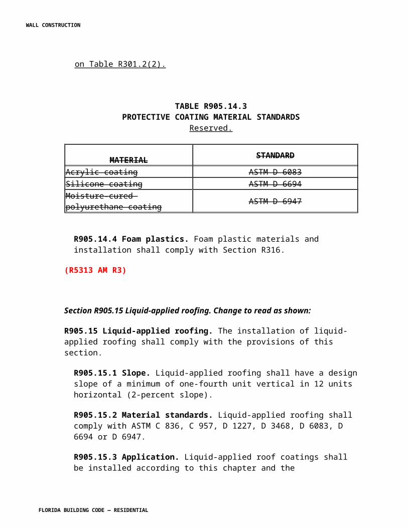
R4402.6.6 Metal roofing accessories. All metal accessories for roofs shall be not less than 26 gauge G-90 galvanized or stainless steel, 16 ounce copper, 0.025-inch (0.6 mm) thick aluminum, lead sheet with a minimum 2.5 pound per square foot (12.2 kg/m2) or equivalent noncorrosive metal alloys or composite materials manufactured for use as roof termination. All composite and nonmetallic flashing materials shall have Product Approval. R4402.6.6.1 Metal accessories may be of a manufactured, shop fabricated or field fabricated type, providing the materials and fasteners are in compliance with the minimum requirements of this code and shall be sized, designed and installed in compliance with methods set forth in RAS 111. R4402.6.6.2 Gravel stop or drip edge profiles shall be as follows: R4402.6.6.2.1 The vertical face shall be a minimum of 1 ½ inches (38 mm) and shall extend down not less than ½ inch (12.7 mm) below the sheathing or other member immediately contiguous thereto. In all cases, the deck flange shall be not less than 2 inches (51 mm) in width. Gravel stop or drip edge shall be sized, designed and installed in compliance with RAS 111. R4402.6.6.2.2 Gravel stop or drip edge shall be designed so that the bottom (the kick of the metal) of the drip edge shall have a minimum of ½ -inch (12.7 mm) clearance from the structure. R4402.6.6.2.3 Reserved. R4402.6.6.2.4 Gravel stops shall be installed after all roofing felts have been applied, or in compliance with the application method set forth in the roofing assembly product approval. All asphalt or approved cold adhesive bonding areas shall be coated with ASTM D 41 or ASTM D 43, as required, and allowed to dry prior to application. R4402.6.6.2.5 Gravel stop and drip edges shall be joined by lapping a minimum of 4 inches (102 mm) and the entire interior of the joints shall be coated with approved flashing cement. Cover and splice plates shall be of the same material as the gravel stop and drip edge, and shall be sized, fabricated and installed in compliance with RAS 111. R4402.6.6.2.6 The deck flange shall be nailed with an approved minimum 12 gauge annular ring shank nail at 4 inches (102 mm) o.c. The nail shall be manufactured from similar and/or compatible material to the termination profile. All composite materials shall be fastened with nonferrous nails.
SECTION R4402.7HIGH-VELOCITY HURRICANE ZONES —
ROOF COVERINGS WITH SLOPES 2:12 OR GREATER R4402.7.1 General. Prepared roof coverings shall be as defined in Section R4402.2 and in general limited to application over sloped roof decks capable of receiving mechanical fasteners.
WALL CONSTRUCTION
FLORIDA BUILDING CODE — RESIDENTIAL
Prepared roof coverings may be mechanically fastened or, in specific limited cases noted in the Product Approval, set in an adhesive bond. R4402.7.2 Underlayments. Underlayment shall be as defined in Section R4402.2. Underlayment shall be installed in compliance with the roofing component Product Approval and shall be in compliance with the following minimum requirements: R4402.7.2.1 Underlayment shall be attached to a nailable deck in a grid pattern of 12 inches (305 mm) between the side laps, with 6-inch (152 mm) spacing at the side laps. R4402.7.2.2 Where the architectural appearance of the underside is to be preserved, the underlayment shall be secured in accordance with Section R4402.8.5.2. R4402.7.2.3 Tin caps and nails or cap nails shall be as defined in Section R4402.6.5.2. R4402.7.2.4 Underlayment nails shall be as defined in R4402.6.5.1. R4402.7.3 If the underlayment is a self-adhering membrane, the membrane shall be applied over a mechanically attached anchor sheet, attached in compliance with R4402.7.2.1. R4402.7.4 All underlayment applications for prepared roof coverings shall be applied in compliance with the manufacturer roofing assembly Product Approval, and shall be not less than one of the following: (1) A double layer of an ASTM D 226 Type I, with a 19 inch headlap; or (2) A single layer of an ASTM D 226, Type II with a 4-inch (102 mm) headlap; or (3) A single layer of an ASTM D 2626 coated base sheet with a 4 inch (102 mm) headlap, and (4) All endlaps shall be a minimum of 6 inches (152 mm). R4402.7.5 Fiber cement shingles. Fiber-cement shingles shall be applied in compliance with the shingle manufacturer's roofing assembly Product Approval. The roofing system assembly product approval shall meet the following minimum requirements: R4402.7.5.1 All non-asbestos fiber-cement shingles shall conform to ASTM C 1225. R4402.7.5.2 Fiber-cement shingles shall be installed in compliance with the nailing requirements set forth in the product approval; however, attachment of each component shall be with not less than two corrosion resistant fasteners. If adhesive is used at the head or side laps, the system shall be defined as a "sealed system" with load calculations in compliance with Section R4403. R4402.7.5.3 All intersections shall be flashed in metal as provided in Section R4402.6.6 and RAS 111. R4402.7.5.4 Fiber-cement shingles shall be tested as set forth in Section R4402.12. R4402.7.6 Quarry slate. Quarry slates shall be applied in compliance with the slate manufacturer's Product Approval. The roofing assembly Product Approval shall meet the following minimum requirements:
WALL CONSTRUCTION
FLORIDA BUILDING CODE — RESIDENTIAL
R4402.7.6.1 Quarry slates shall be installed with not less than two approved fasteners per slate. R4402.7.6.2 All terminations and intersections shall be flashed in metal as provided in Section R4402.6.6 and RAS 111. R4402.7.6.3 Quarry slates shall be tested in compliance with the requirements set forth in Section R4402.12. R4402.7.6.4 Installation of all quarry roof slates shall be limited to a roof mean height of 33 feet (10 m), unless otherwise specifically noted in the Product Approval. R4402.7.7 Asphaltic shingles. Asphaltic shingles layout, alignment and placement of mechanical attachment shall be in compliance with the Product Approval, and shall be installed in accordance with RAS 115. R4402.7.7.1 Underlayments exceeding minimum underlayments, as detailed in Section R4402.7, shall be applied in compliance with the application methods detailed in the Product Approval. Where the architectural appearance of the underside of the roof is to be preserved, refer to Section R4402.8.5.2. R4402.7.7.2 Installation of all asphaltic shingles shall be limited to a roof mean height of 33 feet (10 m), unless otherwise specifically noted in the Product Approval. R4402.7.7.3 The asphaltic shingle Product Approval shall meet the following minimum requirements: R4402.7.7.3.1 Where asphaltic shingles are to be installed over insulated roof deck, a suitable nailable substrate, in accordance with Section R4402.9.5.7 must be installed over the insulation prior to the installation of approved underlayment and shingles. R4402.7.7.3.2 Asphaltic shingles shall be installed in compliance with the Product Approval, but in no case with less than six approved roofing nails or approved fastening devices which penetrate through the thickness of sheathing or wood plank a minimum of 3/8 inch (4.8 mm) or penetrate into a 1 inch (25 mm) or greater thickness of lumber a minimum of 1 inch (25 mm), except where architectural appearance is to be preserved, in which case a minimum of 3/4 inch (19 mm) ring shank roofing nail may be used. R4402.7.7.3.3 Intersections, eaves, rakes, valleys, gable ends, and the starter course of asphaltic shingles shall be set in an 8-inch (203 mm) wide bed of approved cold adhesive or roofing cement. Application of adhesive or cement shall be in compliance with the application instructions of the Product Approval. Shingles shall not extend more than ¼ inch (6.4 mm) beyond the eave drip. R4402.7.7.3.4 All perimeter termination and valleys shall be fabricated from metal. Minimum metal requirements are set forth in Section R4402.6.6, and RAS 111.
WALL CONSTRUCTION
FLORIDA BUILDING CODE — RESIDENTIAL
R4402.7.7.3.5 Asphaltic shingles shall be tested in compliance with the provisions set forth in Section R4402.12. R4402.7.8 Clay and concrete roof tile. Tile shall be clay, concrete or composition material of various configurations complying with the physical property requirements of this code. All tile and tile systems shall be tested in compliance with the provisions set forth in Section R4402.12. Tile shall have a Product Approval for a complete tile system, which shall include the tile, underlayment and all tile related accessories required to provide a waterproof system. R4402.7.8.1 Application. All tile systems shall be installed over solid sheathed decks. All tile installation shall be in accordance with RAS 118, RAS 119, and RAS 120, as applicable. R4402.7.8.1.1 Roof tile mortar shall either be a pre-mixed unit having a Product Approval and tested in compliance with TAS 123 or a job-site mix approved by the building official and in compliance with TAS 113. R4402.7.8.2 The roof tile product approval shall specify the slope requirement for each tile and underlayment system in accordance with Table R4402.4.2. R4402.7.8.3 All roof tile fasteners shall be tested and comply with the requirements set forth in Section R4402.12. R4402.7.8.4 All tile systems. All tile application designs shall comply with the following limitations in order to withstand the wind loads prescribed in this section, as well as all wind load requirements set forth in Section R4403. R4402.7.8.4.1 Roof tiles systems, combining mechanically fastened tile and mortar and/or adhesive, shall be acceptable. R4402.7.8.4.2 In an air permeable tile roofing systems: (1) the length of each tile shall be not less than 12 inches (305 mm) and not greater than 21 inches (533 mm) and the exposed width of the tile shall be between 8.5 inches and 15 inches (216 and 381 mm); (2) the maximum thickness of the nose (leading edge) of the tile shall not exceed 1.3 inches (33 mm); and (3) mortar or adhesive set system shall have at least two-thirds of the tile free of mortar and/or adhesive contact. R4402.7.8.5 The proposed method of attachment for tile systems which are considered to be air permeable, shall provide sufficient attachment resistance (Mf) (listed in tile product approval) to meet or exceed the moment of resistance (Mr) as determined by following the procedures outlined in RAS 127. The aerodynamic multiplier (k) needed in RAS 127 shall be part of the tile Product Approval and shall be derived from the following formula: For direct deck application k = (0.156) x (b) x (l)2 For batten application k = (0.144) x (b) x (l)2
WALL CONSTRUCTION
FLORIDA BUILDING CODE — RESIDENTIAL
Where b (in feet) = exposed width of the tiles Where l (in feet) = length of tiles R4402.7.8.6 The proposed method of attachment for tile systems which are not considered air permeable shall provide a minimum characteristic force (F') (listed in tile product approval) to meet or exceed the required uplift resistance (Fr) as determined by following the procedures outlined in RAS 127. R4402.7.8.7 Tile systems shall extend beyond the drip edge (not including the rake) not less than ¾ inch (19 mm) but not more than 2 inches (51 mm). R4402.7.8.10 Mortar or adhesive set tiles applied at an incline from 6:12 up to and including 7:12 shall have the first course of tile (this applies to pan only on two-piece barrel tile) mechanically fastened with not less than one fastener per tile. As an alternate, the first course of tile shall be applied in mortar over a single layer of minimum 20 gauge galvanized wire mesh with openings of not less than ½ inch (12.7 mm) or greater than 1 ½ inches (38 mm) with minimum exposure of 12 inches (305 mm) which is mechanically attached to the deck through the underlayment with approved fasteners and tin-cap when back nailing the cap sheet. Additionally, for roof inclines of 6:12 up to and including 7:12, every third tile of every fifth course, shall be mechanically fastened with not less than one fastener per tile. For roof inclines above 7:12, in addition to the mortar or adhesive, all tiles shall be mechanically fastened with not less than one fastener per tile. Apply approved flashing cement to seal all tile fastener penetrations, for all roof inclines. R4402.7.8.11 All tile systems shall be shingle lapped interlocking and installed with the headlap as specified in the tile system Product Approval. In no case shall the minimum headlap be less than 2 inches (51 mm) for mortar or adhesive set tile, or less than 3 inches (76 mm) for mechanically set tile, unless restricted by product design. R4402.7.8.12 Where tiles are to be installed over an insulated roof deck, a suitable nailable substrate, in accordance with Sections R4402.9.5.6 and R4402.9.5.7 must be installed over the insulation prior to the installation of approved underlayment and tiles. R4402.7.8.13 For mortar or adhesive set tile, no more than two tiles shall be loose per roofing square [100 square feet (9.3 m2)]. No loose tile shall be adjacent to each other. R4402.7.9 Metal panels/shingles. Steel panels/shingles shall be a minimum of G-90 corrosion resistant, and shall be not less than 26 gauge in thickness. Aluminum panels/shingles shall not be less than 0.025-inch (0.685 mm) thick. All other metal panel/shingle products shall be an equivalent weight. All metal panel/shingle assemblies shall be capable of withstanding foot traffic without damage to the metal panels/shingles. Metal panels/shingles shall have Product Approval for a complete metal system, which shall include the panel/shingle, underlayment and all related accessories to provide a complete waterproof system.
WALL CONSTRUCTION
FLORIDA BUILDING CODE — RESIDENTIAL
R4402.7.9.1 All metal panels/shingles assemblies shall be tested in accordance with Section R4402.12, and TAS 125. R4402.7.9.2 The entire application method of all metal panel/shingle systems shall be detailed in the Product Approval and RAS 133, as applicable. R4402.7.9.3 Metal shingles may be applied as a recover over a single layer of asphaltic shingles or smooth surface roofing, providing the deck is solid sheathed and in compliance with the provisions of this code, the existing prepared roof covering is in compliance with provisions of this code and the entire metal shingle system is applied as set forth in the Product Approval. R4402.7.9.4 Metal panel/shingle systems shall not extend more than 1 inch (25 mm) beyond the roof eave. R4402.7.9.5 All intersections shall be flashed in metal as provided in Section R4402.6.6, RAS 111 and the roof assembly Product Approval. R4402.7.10 Wood shingles and shakes. All wood shingles and shakes shall be installed in accordance with RAS 130. Installation of all wood shingles and shakes shall be limited to a roof mean height of 33 feet (10 m), unless otherwise specifically noted in the Product Approval. R4402.7.10.1 All wood shingle/shake systems shall be tested in accordance with Section R4402.12.R4402.7.11 Building integrated photovoltaic roofing modules/shingles. The installation of building integrated photovoltaic roofing modules/shingles shall comply with the provisions of this section.R4402.7.11.1 Material standards. Building integrated photovoltaic roofing modules/shingles shall be listed and labeled in accordance with UL 1703. R4402.7.11.2 Attachment. Building integrated photovoltaic roofing modules/shingles shall be attached in accordance with the manufacturer’s product approval.1518.11.3 Wind resistance. Building integrated photovoltaic roofing modules/shingles shall be tested in accordance with procedures and acceptance criteria in TAS 107. Building integrated photovoltaic roofing modules/shingle packaging shall bear a label to indicate compliance with the procedures in TAS 107.
SECTION R4402.8HIGH-VELOCITY HURRICANE ZONES —
ROOF COVERINGS WITH SLOPES LESS THAN 2:12 R4402.8.1 General. All adhered roofing components shall be bonded to the various types of substrates in compliance with the requirements set forth in the roofing assembly Product Approval and the following minimum requirements. The authority having jurisdiction may adopt RAS 150 as the means of complying with the requirements listed in this section. R4402.8.2 All packaged asphalt shall have the following data printed on the carton wrapper:
WALL CONSTRUCTION
FLORIDA BUILDING CODE — RESIDENTIAL
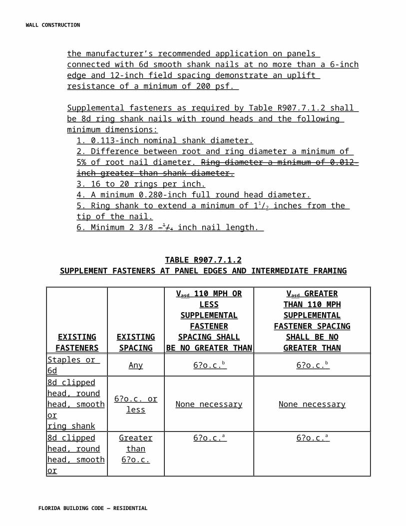
R4402.8.2.1 ASTM designation and type; R4402.8.2.2 Flash point as determined by ASTM D 92, Flash and Fire Point , by Cleveland open cup; and R4402.8.2.3 Equiviscous temperature (EVT) at which the asphalt attains a viscosity of 125 centipoise (25 centipoise for coal tar) as determined by ASTM D 4402, Viscosity Determinations of Unfilled Asphalt Using The Brookfield Thermoset Apparatus. R4402.8.3 Asphalt types, as defined by ASTM D 312, shall be employed in all roofing assemblies. Application of asphalt shall be in compliance with Table R4402.8.3A and Table R4402.8.3B or as detailed in the roofing assembly Product Approval.
TABLE R4402.8.3ASLOPE AND APPLICATION TEMPERATURE CRITERIA
ASTM D312 TYPES OF ASPHALT
MAXIMUM1SLOPE(in./ft) TEMPERATURE°F
MOPMECHANICAL
Type I Dead level 1/4 350 +/-25 375 +/-25
Type II Flat 1/2 400 +/-25 425 +/-25Type III Steep 3 425 +/-25 450 +/-25
Type IV Special steep (All roof tile systems) N/A 450 +/-25 475 +/-25
1 inch = 25.4 mm; C° = [ (°F)-32)]/1.81. Temperature and slope measurements are at point of application
TABLE R4402.8.3B
SLOPE AND APPLICATION TEMPERATURE CRITERIA
ASTM 450 COAL TAR TYPE NO.
TYPE OF COAL TAR
MAXIMUM SLOPE (in./ft)
TEMPERATURE RANGE (°F)
Type I Coal tar pitch 1/4 360 +/-25Type III Coal Tar bitumen 1/4 375 +/-25
1 inch = 25.4 mm;C° = [ (°F)-32)]/1.8
R4402.8.4 Back nailing of inter-ply sheets shall not be required when using ASTM D 312 Type IV asphalt on slopes less than 3:12.
WALL CONSTRUCTION
FLORIDA BUILDING CODE — RESIDENTIAL
R4402.8.5 Mechanical attachment. All mechanically attached roofing components shall be attached to the various types of substrates in compliance with the requirements set forth in the roofing assembly Product Approval and the following minimum requirements. R4402.8.5.1 Base sheet attachment on wood decks. Nails shall be minimum 12 gauge, annular ring shank nails having not less than 20 rings per inch; heads not less than 3/8-inch (9.5 mm) in diameter; and lengths sufficient to penetrate through the thickness of plywood panel or wood plank decking not less than 3/16 inch (4.8 mm), or to penetrate into a 1-inch (25.4 mm), or greater, thickness of lumber not less than 1 inch (25.4 mm). Nails shall be hot dipped; electro or mechanically galvanized to a thickness sufficient to resist corrosion in compliance with Appendix E of TAS 114. All nails shall be Product Approved. All nail cartons or carton labels shall be labeled to note compliance with the corrosion resistance requirements. No roofing material shall be fully or partially adhered, unless otherwise noted in the roof assembly Product Approval directly to a nailable deck. R4402.8.5.1.1 Tin caps shall meet the requirements of Section 4402.6.5.2. R4402.8.5.1.2 Prefabricated fastener systems complying with Sections R4402.8.5.1 and R4402.8.5.1.1 may be used, provided they have Product Approved. R4402.8.5.1.3 Spacing of such fasteners shall be in compliance with patterns set forth in the roofing assembly Product Approval. R4402.8.5.2 Where the architectural appearance of the underside is to be preserved, a base sheet may be secured in an alternate method of attachment prepared, signed, and sealed by a Florida-registered architect or engineer, or in buildings where the mean roof height does not exceed 15 feet (4.6 m), a base sheet may be secured with 1 ¼ -inch (32 mm) fasteners on supporting members, with a minimum of ½ -inch (12.7 mm) fasteners between the supporting members, all of which shall be secured through tin caps and nailed 6 inches (152 mm) o.c. in all directions. R4402.8.5.3 Lightweight insulating concrete. All lightweight insulated concrete shall be vented per roofing system manufacturer recommendations. R4402.8.5.3.1 Lightweight concrete shall not be applied over an existing roof deck unless the supporting structure has been approved as adequate to sustain the added weight. Calculations verifying the adequacy of the existing structure to sustain the added weight shall be prepared, signed, sealed and dated by a Florida-registered architect or engineer, which architect or engineer is proficient in structural design, and submitted with the uniform roofing permit application. R4402.8.5.4 Other nailable decks. The mechanical attachment of roofing components to other nailable decks shall be governed by the roofing assembly Product Approval. R4402.8.6 Cast-in-place and precast structural concrete decks. Cast-in-place and precast structural concrete decks are considered non-nailable. Concrete decks shall be clean, dry and fully primed with ASTM D 41 or ASTM D 43, as required, primer applied at a rate of not less
WALL CONSTRUCTION
FLORIDA BUILDING CODE — RESIDENTIAL
than 1 gallon (3.8 L) per square. Hot asphalt or cold adhesive shall not be applied until the primer has fully dried. R4402.8.7 Steel decks. Steel decks shall be covered with a roof insulation panel having its own Product Approval and listed in the roofing assembly product approval. Insulation panels shall be mechanically fastened in compliance with the mechanical attachment patterns listed in the roofing assembly product approval, and in accordance with the provisions of RAS 117. R4402.8.7.1 If the deck thickness, on an existing steel deck, is less than 22 gauge, a field fastener withdrawal resistance test shall be conducted, in compliance with TAS 105, to confirm compliance with the wind load requirements of Section R4403. Test results shall be submitted with the uniform roofing permit application for review prior to issuance of the roofing permit. The field fastener withdrawal resistance test shall be carried out by a certified testing laboratory. R4402.8.7.2 Steel decks shall be welded or mechanically attached to the structure in compliance with the design pressure requirements set forth in Section R4403. R4402.8.7.3 Composite wood and insulation panels shall be mechanically attached to steel decks in compliance with the attachment requirements enumerated in the insulation roofing component Product Approval. The composite wood insulation panel shall be in compliance with the minimum sheathing requirements of this code. R4402.8.8 Flashing. All flashing shall be installed according to the roof assembly manufacturer's published details and literature and in accordance with RAS 111. R4402.8.9 Valleys. Valleys in BUR shall be installed in according to the roof assembly manufacturer's published literature for high wind areas and in compliance with the applicable detail described in the Product Approval. R4402.8.10 Parapet walls. All parapet wall details shall be installed in accordance with the roofing system product approval, manufacturer's published details and literature and in accordance with approved methods detailed in RAS 111. R4402.8.11 Insulation. Roof insulation shall be applied in compliance with the roofing system Product Approval and RAS 117. R4402.8.12 Surfacing. Roofing assemblies shall be surfaced in compliance with the Product Approval. Surfacing shall be in sufficient quantity to comply with the required fire classification. Aggregate surfacing shall not be used on slopes greater than 3:12. Aggregate shall be embedded in a flood coat of bitumen applied over a prepared top ply. R4402.8.12.1 On slopes of 3:12 or less, not less than 400 pounds (182 kg) of roofing gravel or 300 pounds (145 kg) of slag per square shall be applied. A minimum of 50 percent of the total aggregate shall be embedded in the flood coat of bitumen. Aggregate shall be dry and free from dirt and shall be in compliance with the sizing requirements set forth in ASTM D 1863. A building official may as an option, request a test to confirm compliance with these requirements.
WALL CONSTRUCTION
FLORIDA BUILDING CODE — RESIDENTIAL
R4402.8.12.2 On inclines greater than 3:12, a smooth surface coating shall be applied. R4402.8.12.3 Mineral surfaced cap sheet applications shall not require any additional surfacing unless required with the particular assembly for a fire classification. R4402.8.12.4 All smooth surface applications shall be coated with an aluminized or emulsion coating, having a valid and current Product Approval and shall be in compliance with the application instructions in said Product Approval. Coating quantity shall be in compliance with the required fire rating classification for the structure. R4402.8.13 Attachment of metal termination. All edge metal and terminations shall be installed according to manufacturers published literature, provided it meets the minimum requirements as set for in RAS 111 and Section R4403. R4402.8.14 Expansion joints. Expansion joint covers and expansion joint components shall be constructed and installed in accordance with the roofing assembly manufacturer's published literature. R4402.8.15 Venting roofing assemblies. All roof assemblies shall be applied to a dry substrate. Vapor retarders shall be installed, where applicable, to reduce moisture vapor flow into insulation from the warm, humid building interior, leading to internal condensation. Vents shall be installed to assist in the expulsion of moisture vapor where such vapor may enter the roofing assembly or moisture, as defined in Section R4402.11.12, has been left in an existing roofing assembly. Venting units shall not allow vapor to enter the roofing assembly when the high vapor pressure side is above the roofing membrane. R4402.8.16 Waterproofing. Waterproofing systems may be installed in lieu of an approved roof system over sloped or horizontal decks specifically designed for pedestrian and/or vehicular traffic, whether the deck is above occupied or unoccupied space. In new construction the minimum deck slope shall be ¼ : 12. R4402.8.16.1 The waterproofing system must possess a current and valid product approval. R4402.8.16.2 If an overburden or wearing surface is not to be installed, the waterproofing system must be approved by the manufacturer for use in vehicular and/or pedestrian traffic locations. R4402.8.16.4 If any portion of the waterproofing membrane is to remain exposed, the waterproofing system shall be ultraviolet resistant. R4402.8.16.5 Flashings must be installed according to the waterproofing manufacturer's published specifications and in compliance with the material and attachment standards of RAS 111. R4402.8.16.6 The waterproofing system shall be flood tested in accordance with ASTM D 5957.
WALL CONSTRUCTION
FLORIDA BUILDING CODE — RESIDENTIAL
R4402.8.16.6.1 The flood test shall take place after installation of the waterproofing membrane and prior to the installation of any above membrane components, wearing surface or overburden. R4402.8.16.6.2 An approved testing lab shall provide written verification to the building official confirming that the flood test was performed along with the results, prior to final inspection.
SECTION R4402.9HIGH-VELOCITY HURRICANE ZONES —
ROOF INSULATION R4402.9.1 General. All roof insulation shall have Product Approval as an approved roofing component for use in roofing assemblies. All insulation shall be tested for physical properties in accordance with TAS 110. R4402.9.2.1 Foam insulation panels shall be overlaid with a perlite, fiberglass, wood fiber or mineral wool overlay unless specifically stated to the contrary in the roof assembly Product Approval. R4402.9.4 Insulation fasteners, membrane fasteners and stress plates. All Insulation fasteners, membrane fasteners and stress plates shall have a roof component Product Approval, and shall be tested in compliance with RAS 117, Appendixes A, B and C, and TAS 110 and TAS 114, Appendix E, Section 3 (DIN 50018), for corrosion resistance. R4402.9.5 Application. Roof insulation shall be applied in strict compliance with the application methods detailed in the roof assembly Product Approval and with the requirements set forth in RAS 117. R4402.9.5.1 Roof insulation, either on the ground or on the roof top, shall be kept dry. The building official shall instruct the removal of the insulation from the job when elevated moisture levels are found in the insulation or where panels cannot achieve 85 percent adhesion. R4402.9.5.2 When applied in hot asphalt or cold adhesive, no insulation panel's dimension shall be greater than 4 feet (1219 mm). R4402.9.5.3 Strip or spot mopping of insulation panels shall be used as an application method only when approved in the roof assembly Product Approval. R4402.9.5.4 Where more than one layer of insulation is applied, joints between layers shall be staggered.
WALL CONSTRUCTION
FLORIDA BUILDING CODE — RESIDENTIAL
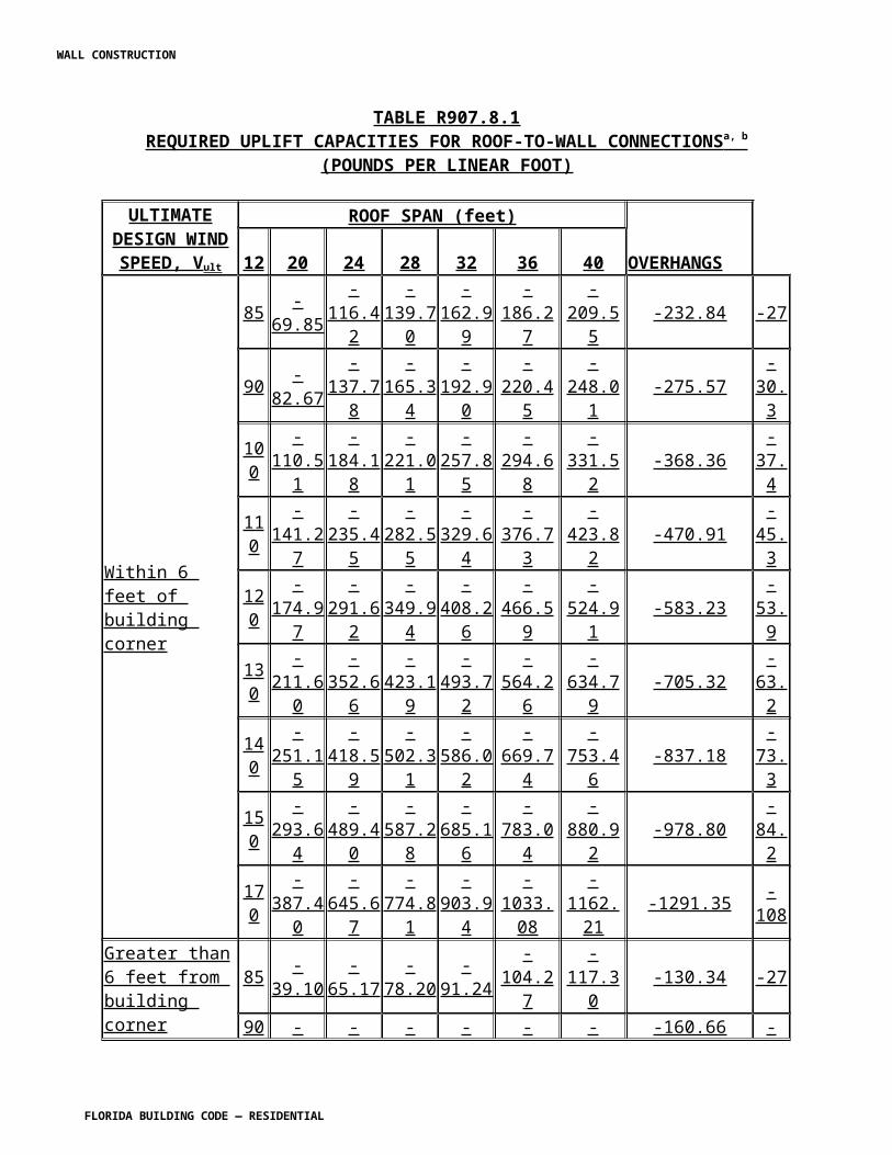
R4402.9.5.5 Application in approved cold adhesive shall be as detailed in the Product Approval and shall be in compliance with the required fire classification. R4402.9.5.6 Nail boards or composite panels with a nailable surface may be applied to sloped decks for the application of prepared roof covering or metal roofing systems, providing that the nailing surface is minimum 15/32-inch (12 mm) exterior grade plywood sheathing, and has been attached to the deck with approved fastening assemblies in accordance with the windload requirements of Section R4403. Composite panels shall be gapped a minimum of 1/8 inch (3.2 mm) to allow for expansion of the sheathing panel. R4402.9.5.7 Suitable nailable decks installed over rigid board roof insulation in buildings of mean roof height of 35 feet (10.7 m) or less, shall be a minimum of 15/32 -inch (12 mm) exterior grade plywood sheathing. These decks shall be fastened to every structural roof frame member or to the existing deck under the insulation, at intervals of not more than 24 inches (610 mm) apart, with a minimum #12 approved insulation fastener spaced at a maximum of 12 inches (305 mm) apart in one direction with a minimum penetration of 1½ inches (38 mm) into the structural member or deck. In these cases the maximum thickness of the rigid insulation board shall not exceed 2 inches (51 mm). An alternate method of attachment may be proposed, provided it is in compliance with Section R4403, and it is prepared, signed and sealed by a Florida-registered architect or a Florida professional engineer, which architect or engineer shall be proficient in structural design. R4402.9.5.8 Mechanical attachment of insulation panels at uneven areas shall be acceptable. Hollowing, cutting or scoring of insulation panels to provide contact shall not be acceptable.
SECTION R4402.10HIGH-VELOCITY HURRICANE ZONES —
REROOFING R4402.10.1 General. Materials and methods of application used for recovering or replacing an existing roof covering, system or assembly shall comply with the requirements set forth in Sections R4402.1 through R4402.14. R4402.10.2 Repairs shall be carried out with roofing components as defined in this section having Product Approval. R4402.10.3 Repairs shall be carried out in such a manner as to not to create additional ponding water. R4402.10.4 Not more than 25 percent of the total roof area or roof section of any existing building or structure shall be repaired, replaced or recovered in any 12-month period unless the entire existing roofing system or roof section is replaced to conform to requirements of this code. R4402.10.5 A roofing system shall not be applied over an existing roof or over an existing roof deck where the roof sheathing has not been fastened in compliance with this code or where the
WALL CONSTRUCTION
FLORIDA BUILDING CODE — RESIDENTIAL
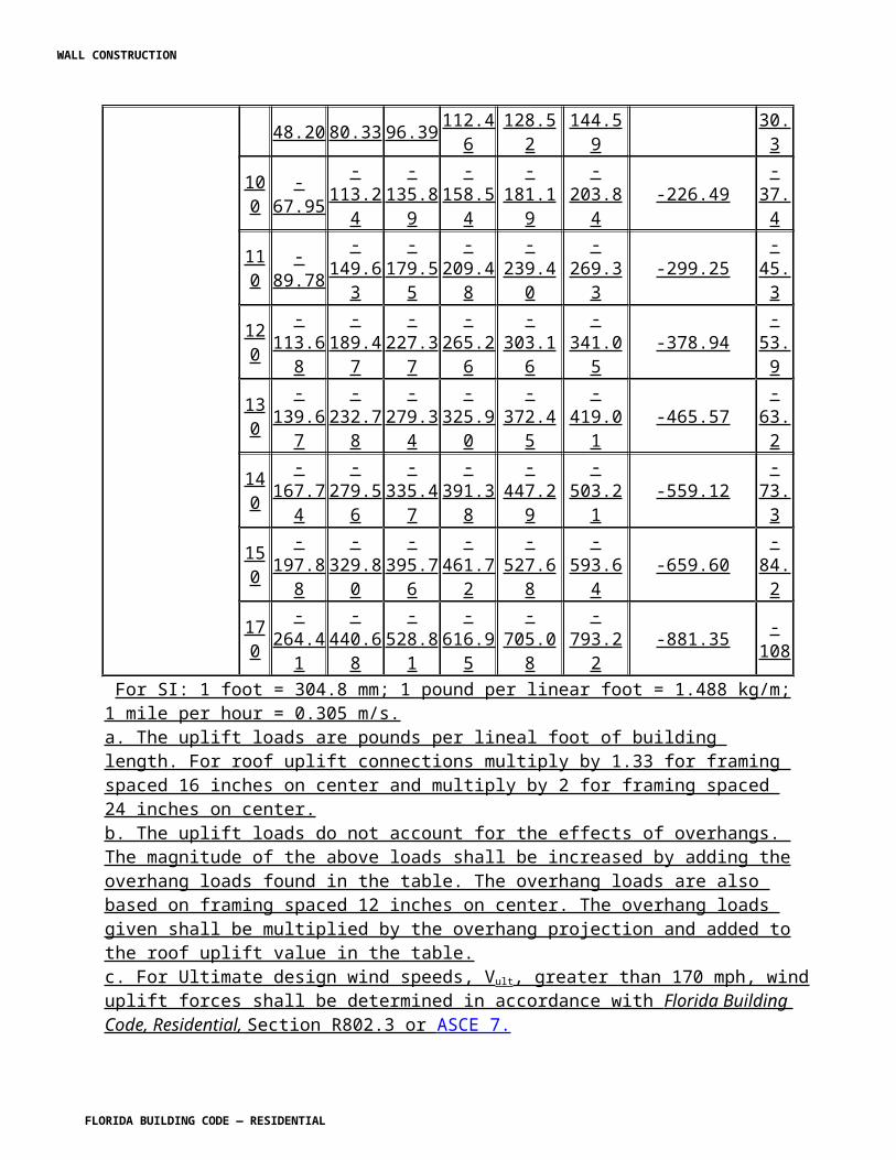
roof sheathing will not permit effective fastening or where sheathing is water soaked or deteriorated so that effective attachment is not possible. All areas of deteriorated sheathing shall be removed and replaced. The building official shall not be required to inspect the renailing of the sheathing under this section. R4402.10.6 Structural concrete decks shall be allowed to dry or shall be dried prior to application of an ASTM D 41 or ASTM D 43, as required, or roofing system proprietary primer where the base sheet or base insulation layer is bonded to the concrete deck. R4402.10.7 On lightweight concrete, gypsum and cementitious wood fiber roof decks a field fastener withdrawal resistance test, in compliance with TAS 105, shall be carried out to confirm compliance with wind load requirements of Section R4403. R4402.10.7.1 If the tested fasteners exhibit a minimum characteristic resistance force less than 80 percent than that listed in the product approval, a structural engineer shall examine the deck's integrity and provide a proposed attachment specification. Such specification shall be submitted with the uniform roofing permit application for review and approval by the building official prior to the issuance of a roofing permit. Calculations for the attachment of the anchor sheet/base sheet or insulation over these deck types, shall be in compliance with RAS 117. R4402.10.8 Steel decks shall be examined prior to recover for indication of corrosion. Any corrosion identified and exposed on the roof side shall be treated with a rust inhibitor, providing the field fastener withdrawal resistance values of the proposed mechanical fasteners comply with the requirements of Section R4403 of this code. All steel decks less than 22 gauge shall be field tested for fastener withdrawal resistance for compliance with Section R4403 prior to application of a new roofing system. Test results shall be submitted with the uniform roofing permit application. R4402.10.9 One additional roofing system may be applied over an original roofing assembly, providing the existing roofing assembly complies with the requirements of Section R4402.10. R4402.10.10 If the recover roofing assembly is to be bonded to an existing roofing membrane, the existing roofing membrane shall be tested in compliance with TAS 124 for uplift resistance. The existing roofing membrane shall resist the design pressures calculated under Section R4403 of this code. Test results shall be submitted with the uniform roofing permit application. R4402.10.11 If the recover roofing assembly is mechanically attached through either a base sheet or insulation layer, the attachment assembly shall be field tested for fastener withdrawal resistance, in compliance with TAS 105, and laboratory tested for pull-over resistance to ensure compliance with wind uplift requirements set forth in Section R4403 of this code. Test results shall be submitted with the uniform roofing permit application. Recover roofing assembly anchor sheet or base sheet shall not be mechanically fastened directly to existing gravel roof unless all gravel is completely removed.
WALL CONSTRUCTION
FLORIDA BUILDING CODE — RESIDENTIAL
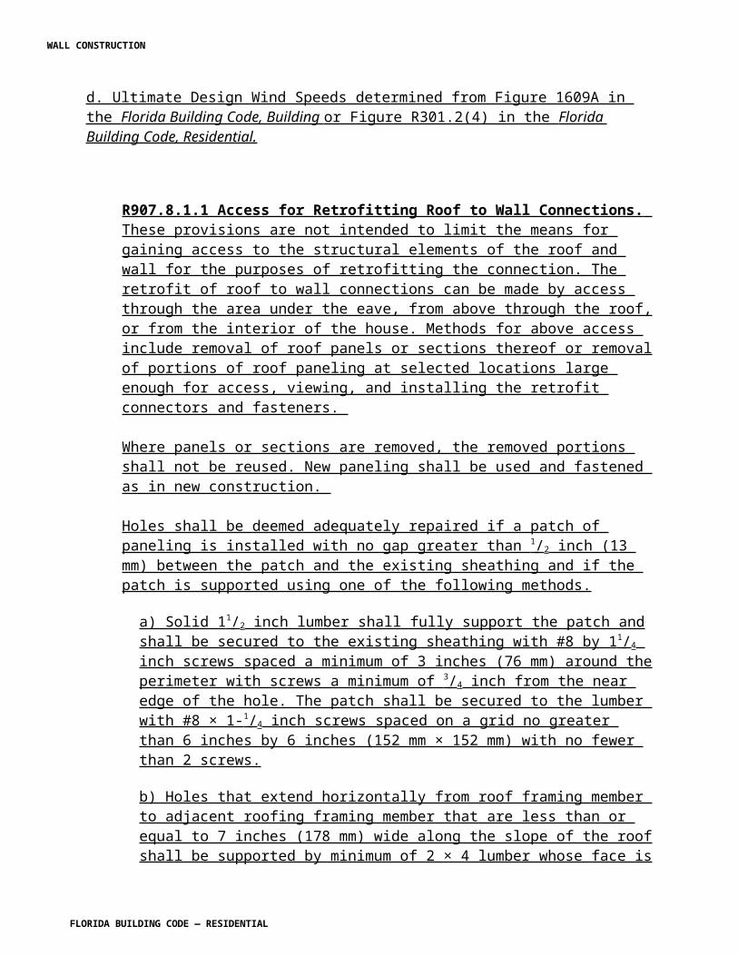
R4402.10.12 Moisture content of the existing roofing assembly to be covered by a new roofing system shall not exceed 5 percent by weight in the roofing membrane and 8 percent by weight in the insulation system, as verified by moisture survey performed in accordance with TAS 126. Test results shall be submitted with the uniform roofing permit application. R4402.10.13 Prior to starting the work the contractor has the responsibility of notifying the owner, by means of the roofing permit and required owners notification for roofing considerations herein, of any possibility of ponding water and recommend a structural review if ponding water is a possibility. R4402.10.14 If the new roofing system is to be bonded to the existing roof surface, the surface shall be free of all loose gravel, dirt and silt and dry prior to commencement of the roofing application. All blisters shall be cut and repaired prior to roofing application. R4402.10.14.1 If the existing roof surface has gravel embedded in hot asphalt, all loose gravel shall be removed together with any dirt and silt. The dry membrane surface shall be primed with ASTM D 41 primer or proprietary roofing system primer and allowed to dry thoroughly. A flood coat of ASTM D 312, type III or IV asphalt shall be applied to sufficient depth to cover the remaining embedded gravel. The prepared substrate shall be suitable for application of a new insulation layer only. R4402.10.14.2 In the case of existing coal tar assemblies, the existing roof surface shall be primed with ASTM D 43 primer or covered with a mechanically attached separation board prior to application of a new coal tar assembly. If an existing coal tar assembly is to be covered with an asphalt applied roofing system, only the separation board is acceptable. The attachment of the entire assembly, including the separation board, shall meet the design pressure requirements set forth in Section R4403. R4402.10.14.3 Insulation shall have product approval as a roofing component approved for use as a part of the roofing assembly. The insulation panels shall be bonded or mechanically attached in compliance with the Product Approval and RAS 117. R4402.10.15 Where an existing sloped roof is sheathed with spaced sheathing, any existing prepared roof covering shall be removed. New sheathing shall be applied in compliance with Section R4403, or open spacing shall be filled with dimensional lumber to create solid wood sheathing providing the spaced sheathing is in compliance with this code. Spaced sheathing is approved for use with wood shakes and wood shingles only. R4402.10.16 No recover application shall take place over existing wood shingles, shakes, slate, tile or metal shingles. R4402.10.17 Asphaltic shingle assemblies may be applied over one existing layer of asphaltic shingles having not more than 1/8 inch (3.2 mm) difference in level in the existing shingle material. Recover over an existing shingle system shall be with a product having Product Approval as prepared roof covering, in strict compliance with the application method detailed in the Product Approval.
WALL CONSTRUCTION
FLORIDA BUILDING CODE — RESIDENTIAL
R4402.10.17.1 Application of elastomeric and or maintenance coating systems over existing asphalt shingles shall be in accordance with the shingle manufacturer’s approved installation instructions.R4402.10.18 Sprayed polyurethane foam (PUF) and elastomeric coating systems may be applied over existing roofing assemblies providing the PUF system has obtained Product Approval, the deck has been prepared in compliance with the Product Approval and this code, the application is in strict compliance with the foam manufacturer's published application instructions for the environmental conditions at the time of application and post-application inspections conform to RAS 109. R4402.10.18.1 No sprayed polyurethane foam (PUF) shall be applied over existing composition shingles. R4402.10.18.2 Upon completion of a PUF system, an inspection of the system shall be carried out by an authorized representative of the coating manufacturer. A certification shall be furnished to the building official within 30 days of completion, confirming that the quality control tests detailed in the PUF system Product Approval have been carried out with satisfactory results. R4402.10.18.3 Should a PUF system have inadequate adhesion to meet the design pressures, as set forth in Section R4403, the roofing system shall be removed and replaced with a roofing system tested to adequate adhesion. An additional inspection shall be required once the roofing system has been replaced. A field adhesion test may be requested by the building official during the application or at the completion of the project to confirm adequate adhesion. R4402.10.18.4 The PUF system shall comply with R4402.10. R4402.10.18.5 All PUF systems shall be installed by licensed roofing contractors holding an applicator's certificate from the manufacturer holding the Product Approval for the PUF system. R4402.10.19 Roof coverings or roofing components, such as tile, slate or similar, shall not be applied over an existing roofing system. R4402.10.20 Lightweight insulated concrete shall not be applied over an existing roofing system unless the existing roofing assembly is verified to be adequate to accept the new lightweight insulating concrete and is in compliance with the testing required herein.
SECTION R4402.11HIGH-VELOCITY HURRICANE ZONES —
ROOFTOP STRUCTURES AND COMPONENTS R4402.11.1 Rooftop structures. Rooftop structures shall be designed and constructed in accordance with the Florida Building Code, Building.
WALL CONSTRUCTION
FLORIDA BUILDING CODE — RESIDENTIAL
R4402.11.2 Rooftop mounted equipment. All rooftop equipment and supports shall be secured to the structure in compliance with the loading requirements of Section R4403. The use of wood "sleepers" shall not be permitted.
SECTION R4402.12HIGH-VELOCITY HURRICANE ZONES —
TESTING R4402.12.1 Scope. This section defines the minimum testing requirements for substrates, roofing components, roofing systems and roofing assemblies. All roofing products shall be tested for physical properties, water-infiltration, uplift performance and fire resistance, as addressed within this code. R4402.12.1.1 Testing requirements for physical properties of all roofing products shall be as set forth in TAS 110. R4402.12.2 Application. Testing for substrates, roofing components, roofing systems and roofing assemblies shall comply with the provisions herein and those of Florida Building Code, Building TAS and RAS listed in this code. R4402.12.3 Laboratory certification. All testing required by this code shall be performed by a certified testing laboratory. R4403.12.4 Margin of safety. A margin of safety of 2:1 shall be applied to all wind uplift resistance test results. All in-situ (on site) testing shall have an applied 1.45:1 margin of safety. R4403.12.5 Material labeling. All products shall be identified with the product approval number or logo; or the manufacturer's name or logo. ASTM standard roll goods shall be marked with a yellow line to identify the ASTM standard, or such other marking indicated in the Product Approval. R4402.12.5.1 All asphaltic shingles, tile products and metal roofing panels and clips shall be labeled on the underside with the Florida Building Code, Building insignia, or Product Approval number, or the wording "Florida Building Code, Building Product Approved," and manufacturer's initials or manufacturer's logo, or as specified in the manufacturer's Product Approval. R4402.12.6 Testing requirements. R4402.12.6.1 Reserved. R4402.12.6.2 Continuous roofing systems. All continuous roofing systems shall be tested in compliance with TAS 110 and TAS 114 in its entirety. All continuous roofing systems shall resist a minimum of 90 pound per square foot (psf) (4309 Pa) tested wind uplift pressure resistance. Continuous roofing system testing requirements shall be as follows:
WALL CONSTRUCTION
FLORIDA BUILDING CODE — RESIDENTIAL
R4402.12.6.2.1 Spray applied polyurethane foam. All spray applied polyurethane foam systems shall be tested in compliance to RAS 109 and TAS 110 and TAS 114. R4402.12.6.2.1.1 Physical properties testing for acrylic coatings used on spray applied polyurethane foam roofing assemblies shall be tested in compliance with ASTM D 6083-97a and Federal Specification TTC-555B, Test Specification for Wind-Driven Rain Infiltration Resistance . R4402.12.6.3 Liquid applied roofing membranes systems. All liquid applied roofing membranes systems shall be tested in compliance with TAS 114, in addition to the physical properties testing requirements set forth in TAS 110, and fire resistance. R4402.12.6.3.1 For liquid applied acrylic roofing membrane assemblies, physical properties testing shall be in compliance with ASTM D 6083-97a and Federal Specification TTC-555B, Test Specification for Wind Driven Rain Infiltration Resistance . R4402.12.6.4 The building official may request that a quality control field uplift test be carried out on a continuous roofing system in compliance with test procedure TAS 124. Single-ply systems are not required to meet the deflection requirements established in the test protocol. The roofing system shall resist the design pressures as calculated in compliance with Section R4403 and as established in TAS 124. R4402.12.6.4.1 Should a roofing system fail to meet a quality control field uplift test, the roofing contractor may propose to the building official an acceptable method of repair that is in compliance with the requirements of this code. R4402.12.6.5 Discontinuous roofing systems. All discontinuous roofing systems shall be tested in compliance with TAS 100 for wind driven water infiltration resistance. Test specimens used for this test shall be constructed at the approved test facility. Testing requirements shall be as follows: R4402.12.6.5.1 Asphaltic shingle systems. All asphaltic shingle systems shall comply with the following requirements: TAS 100, TAS 107, ASTM D 3462 and ASTM D 3018. Asphaltic shingle systems shall have a quality control testing program by an approved independent listing agency. R4402.12.6.5.2 Clay and cement roof tiles. All roof tiles shall be tested in compliance with TAS 100. Physical properties testing for clay roof tiles shall be in compliance with ASTM D 1167. Physical properties testing for concrete roof tiles shall be in compliance with TAS 112. All roof tiles shall resist a minimum wind uplift resistance as determined by Section R4403 of this code and RAS 127. Clay and cement roof tile systems requirements are as follows: R4402.12.6.5.2.1 Underlayment. All underlayments used in discontinuous roof tile systems shall be tested in compliance with TAS 103 and TAS 104, unless otherwise specifically listed in the applicable RAS.
WALL CONSTRUCTION
FLORIDA BUILDING CODE — RESIDENTIAL
R4402.12.6.5.2.2 Mortar or adhesive set roof tile systems. All mortar or adhesive set tile systems shall be tested for static uplift resistance in compliance with TAS 101, the results of which shall be listed in the system manufacturer's Product Approval. R4402.12.6.5.2.2.1 Additionally, roof tile system manufacturers may test for wind characteristics in compliance with TAS 108, provided the system is determined to be air permeable by testing in compliance with TAS 116; and the tiles meet the size criteria set forth in TAS 108. The result from this testing shall be an aerodynamic multiplier (l) which represents the system's wind characteristics and shall be listed in the system manufacturer's Product Approval. R4402.12.6.5.2.2.2 Systems which are tested for characteristics, in compliance with TAS 108 as specified above, shall have the results of the TAS 101 testing treated as attachment resistance moment (Mf), which is representative of the tile bond's resistance to overturning moment, and the tile's restoring moment due to gravity (Mg). Such systems shall use the system's aerodynamic multiplier (l) in conjunction with the system's attachment resistance moment (Mf) and restoring moment due to gravity (Mg), as determined from the TAS 101 static uplift testing. These results shall be used in conjunction with the attachment calculations outlined in TAS 115 as a moment-based system. Such calculations shall be submitted to the building official for review. R4402.12.6.5.2.2.3 Systems that are not tested in compliance with TAS 108 as specified above shall have their Product Approval based on the system's uplift minimum characteristic resistance force (F'), as determined from TAS 101 static uplift testing. These results shall be used in conjunction with the attachment calculations outlined in TAS 115 as an uplift-based system. Such calculations shall be submitted to the building official for review. R4402.12.6.5.2.2.4 Testing in accordance with TAS 106 shall be considered a product application quality control test to determine the general adhesion properties of the system. R4402.12.6.5.2.3 Mechanically fastened, rigid roofing systems. All mechanically attached set tile systems shall be tested for static uplift resistance in compliance with TAS 102 or TAS 102(A), the results of which shall be listed in the system manufacturer's Product Approval. R4402.12.6.5.2.3.1 Additionally, roof tile system manufacturers may test for wind characteristics in compliance with TAS 108, provided the system is determined to be air permeable by testing in compliance with TAS 116; and the tiles meet the size criteria set forth in TAS 108. The result from this testing shall be an aerodynamic multiplier (l) which represents the system's wind characteristics and shall be listed in the system manufacturer's Product Approval. R4402.12.6.5.2.3.2 Systems which are tested for wind characteristics in compliance with TAS 108 as specified above shall have the results of the TAS 102 or TAS 102(A) testing treated as an attachment resistance moment (Mf) which is representative of the rigid component's attachment resistance to an overturning moment, and the tile's restoring moment due to gravity (Mg). Such systems shall use the system's aerodynamic multiplier (l), in conjunction with the system's attachment resistance moment (Mf) and restoring moment due to gravity (Mg), as determined from the TAS 102 or TAS 102(A) static uplift testing. These results shall be used in conjunction
WALL CONSTRUCTION
FLORIDA BUILDING CODE — RESIDENTIAL
with the attachment calculations outlined in TAS 115 as a moment-based system. Such calculations shall be submitted to the building official for review. R4402.12.6.5.2.3.3 Systems that are not tested in compliance with TAS 108 as specified above shall have their Product Approval based on the system's uplift minimum characteristic resistance force (F'), as determined from TAS 102 or TAS 102(A) static uplift testing. These results shall be used in conjunction with the attachment calculations outlined in TAS 115 as an uplift-based system. Such calculations shall be submitted to the building official for review. R4402.12.6.5.2.3.4 TAS 106 quality control field static uplift testing shall be considered a product application quality control test to determine the general uplift resistance properties of the system. R4402.12.6.5.2.4 Metal shingles/panels. All metal roofing shall be tested in compliance with TAS 100. All metal roofing shall resist a minimum wind uplift resistance as determined by Section R4403 for a roof slope of 9.5 degrees (0.0166 rad) and a roof mean height of 15 feet (4.6 m). All metal roofing systems testing requirements shall be as follows: R4402.12.6.5.2.4.1 All metal roofing shall be test in compliance with requirements set forth in TAS 110 and TAS 125, and shall be tested for wind driven rain infiltration resistance in compliance with TAS 100. R4402.12.6.5.2.4.2 Rigid metal shingle systems may be tested in an identical manner to nail-on or batten tile systems as set forth in this code. R4402.12.6.5.2.5 Wood shingles or shakes. All wood shingles and shakes shall be tested, as a system, for wind driven rain infiltration resistance in compliance with TAS 100. The same specimens as tested in TAS 100 shall be tested for pull through tear resistance, and such values shall be listed in the manufacturer's Product Approval. R4402.12.6.5.2.6 Fiber cement shingle or tile panels. All fiber cement shingles or tiles shall resist a minimum wind uplift resistance as determined by Section R4403 for a roof slope of 9.5 degrees (0.0166 rad) and a roof mean height of 15 ft (4.6 m). All fiber cement shingle or tiles shall be tested in compliance with the following requirements. Wind driven water resistance in compliance with TAS 100, Physical properties in compliance with TAS 110, TAS 135 and uplift resistance. R4402.12.6.5.2.6.1 Additionally, fiber cement tile system manufacturers may test for wind characteristics in compliance with TAS 108, provided the system is determined to be air permeable by testing in compliance with TAS 116 and the tiles meet the size criteria set forth in TAS 108. The result from this testing shall be an aerodynamic multiplier (l) which represents the system's wind characteristics and shall be listed in the system manufacturer's Product Approval. R4402.12.6.5.2.6.2 Systems which are tested for wind characteristics in compliance with TAS 108 as specified above shall have the results of the TAS 102 or TAS 102(A) testing treated as an attachment resistance moment (Mf) which is representative of the rigid component's attachment
WALL CONSTRUCTION
FLORIDA BUILDING CODE — RESIDENTIAL
resistance to an overturning moment, and the tile's restoring moment due to gravity (Mg). Such systems shall use the system's aerodynamic multiplier (l), in conjunction with the system's attachment resistance moment (Mf) and restoring moment due to gravity (Mg), as determined from the TAS 102 or TAS 102(A) static uplift testing. These results shall be used in conjunction with the attachment calculations outlined in TAS 115 as a moment-based system. Such calculations shall be submitted to the building official for review. R4402.12.6.5.2.6.3 Systems that are not tested in compliance with TAS 108 as specified above shall have their Product Approval based on the system's uplift minimum characteristic resistance force (F'), as determined from TAS 102 or TAS 102(A) static uplift testing. These results shall be used in conjunction with the attachment calculations outlined in TAS 115 as an uplift-based system. Such calculations shall be submitted to the building official for review. R4402.12.6.5.2.6.4 TAS 106 quality control field static uplift testing shall be considered a product application quality control test to determine the general uplift resistance properties of the system. R4402.12.6.5.2.7 Quarry roof slate. All quarry roof slate shall be tested in compliance with TAS 100 and TAS 110. R4402.12.6.5.2.8 Roof board insulation. All roof board insulation shall be tested for physical properties as set forth in Section 7 of TAS 110. R4402.12.6.5.2.9 Insulation fasteners, membrane fasteners and stress plates. All insulation fasteners, membrane fasteners and stress plates shall be tested in compliance with TAS 117 Appendices A, B and C, and TAS 110 and TAS 114, Appendix E, Section 3, (DIN 50018), for corrosion resistance. R4402.12.6.5.2.10 Roofing nails and tin-caps. All roofing nails and tin-caps shall be tested for corrosion resistance in compliance with TAS 114, Appendix E, Section 2 (ASTM G 85). R4402.12.6.5.2.11 Roof tile nails or fasteners. All roof tile nails or fasteners, except those made of copper, monel, aluminum or stainless steel, shall be tested for corrosion in compliance with TAS 114, Appendix E, Section 2 (ASTM G 85), for salt spray for 1,000 hours. R4402.12.6.5.2.11.1 Tile fasteners used in coastal building zones, as defined in Section R4403 shall be copper, monel, aluminum or stainless steel. R4402.12.6.5.2.12 Roofing adhesives, mastics and coatings. All roofing adhesives, mastics and coatings shall be tested in compliance with TAS 110 and TAS 121. R4402.12.6.5.2.12.1 All roofing adhesives, mastics and coatings shall have a quality control testing program by an approved independent listing agency having unannounced follow-up visits.
WALL CONSTRUCTION
FLORIDA BUILDING CODE — RESIDENTIAL
R4402.12.6.5.2.12.2 Acrylic roof coatings shall be tested for physical properties in compliance with ASTM D 6083-97a. R4402.12.6.5.2.13 Ridge vents of metal, plastic or composition material. All ridge vents shall be tested in compliance with TAS 110(A) for wind driven water infiltration. All ridge ventilators shall be restricted to roof mean height as tested in compliance with TAS 100(A), and shall be listed in the system manufacturer's Product Approval. R4402.12.6.5.2.13.1 All plastic ridge ventilators shall be tested for physical properties as set forth in TAS 110 and R4412. R4402.12.6.5.2.13.2 All plastic ridge ventilator manufacturers shall have an unannounced follow-up quality control program from an approved listing agency. Follow-up test results shall be made available upon request. R4402.12.6.5.2.14 Edge metal, flashings, and coping. All edge metal, flashing and copings, not specifically described in RAS 111, shall be tested in compliance with TAS 110, TAS 111(A), TAS 111(B) or TAS 111(C), respectively. R4402.12.6.5.2.15 Roof tile premixed bagged mortar. All premixed roof tile mortar shall comply with the requirements set forth in TAS 110 and TAS 123, and shall have a quality control testing program by an approved independent listing agency having unannounced follow-up visits. Follow-up test results shall be made available upon request. R4402.12.6.5.2.16 Roof tile adhesive used in repair or supplemental tile attachment. All roof tile adhesive used in repair or supplemental tile attachment shall comply with the requirements set forth in TAS 110 and TAS 123(A). R4402.12.6.5.2.17 Roof tile adhesive used in adhesive set tiles systems. All roof tile adhesive used in adhesive set tile systems shall comply with the requirements set forth in TAS 110 and TAS 123. Physical properties shall be as follows: R4402.12.6.5.2.17.1 Tested for compressive strength in compliance with ASTM D 1621 with a minimum strength of 18 psi (121 kPa) parallel to rise, and 12 psi (82.7 kPa) perpendicular to rise. R4402.12.6.5.2.17.2 Tested for density in compliance with ASTM D 1622 with a minimum density of 1.6 pcf (25.6 kg/m3). R4402.12.6.5.2.17.3 Tested for tensile strength in compliance with ASTM D 1623 with a minimum requirement of 28 psi (193 kPa) parallel to rise. R4402.12.6.5.2.17.4 Tested for dimensional stability taken from a free rise sample specimen. Tested in compliance with ASTM D 2126 with a maximum volume change of +0.07 percent volume change at -40°F (-40°C) for two weeks; and +6.0 percent volume change at 158°F (70°C) and 100 percent RH for two weeks.
WALL CONSTRUCTION
FLORIDA BUILDING CODE — RESIDENTIAL
R4402.12.6.5.2.17.5 Tested in compliance with ASTM D 2856 from a free rise sample specimen with a minimum requirement for 85 percent. R4402.12.6.5.2.17.6 Tested for water absorption in compliance with ASTM D 2842 with a maximum requirement of 10 percent. R4402.12.6.5.2.17.7 Tested in compliance with ASTM E 96 for moisture vapor transmission for a maximum of 3.1 perms.
SECTION R4402.13HIGH-VELOCITY HURRICANE ZONES —
REQUIRED OWNERS NOTIFICATION FOR ROOFING CONSIDERATIONS R4402.13.1 Scope. As it pertains to this section, it is the responsibility of the roofing contractor to provide the owner with the required roofing permit, and to explain to the owner the content of this section. The provisions of Section R4402 govern the minimum requirements and standards of the industry for roofing system installations. Additionally, the following items should be addressed as part of the agreement between the owner and the contractor. The owner's initial in the designated space indicates that the item has been explained. 2. Renailing wood decks: When replacing roofing, the existing wood roof deck may have to be re-nailed in accordance with the current provisions of Section R4403. (The roof deck is usually concealed prior to removing the existing roof system). 4. Exposed ceilings: Exposed, open beam ceilings are where the underside of the roof decking can be viewed from below. The owner may wish to maintain the architectural appearance; therefore, roofing nail penetrations of the underside of the decking may not be acceptable. The provides the option of maintaining this appearance. 6. Overflow scuppers (wall outlets): It is required that rainwater flow off so that the roof is not overloaded from a buildup of water. Perimeter/edge walls or other roof extensions may block this discharge if overflow scuppers (wall outlets) are not provided. It may be necessary to install overflow scuppers in accordance with the requirements of Sections R4402, R4403 and R4413. ______________________________________________Owner’s/Agent’s Signature Date Contractor’s Signature Exception: Attic spaces, designed by a Florida-licensed engineer or registered architect to eliminate the attic venting, venting shall not be required.
WALL CONSTRUCTION
FLORIDA BUILDING CODE — RESIDENTIAL
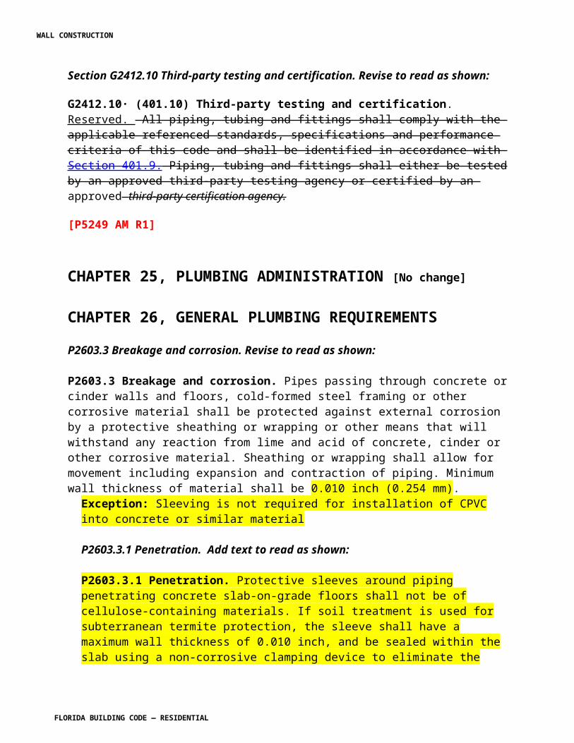
SECTION R4402.14HIGH-VELOCITY HURRICANE ZONES —
UNIFORM PERMIT APPLICATION[see forms as found in the 2010 Residential code]
[U[Mod 5009 AS]
Section R4403. Change to read as follows:
SECTION R4403HIGH-VELOCITY HURRICANE ZONES—
GENERAL R4403.1 General design requirements Refer to Chapter 16 of the Florida Building Code, Building. R4403.1.1 Any system, method of design or method of construction shall admit of a rational analysis in accordance with well-established principles of mechanics and sound engineering practices. R4403.1.2 Buildings, structures and all parts thereof shall be designed and constructed to be of sufficient strength to support the estimated or actual imposed dead, live, wind, and any other loads, both during construction and after completion of the structure, without exceeding the allowable materials stresses specified by this code. R4403.1.6 Floor and roof systems shall be designed and constructed to transfer horizontal forces to such parts of the structural frame as are designed to carry these forces to the foundation. Where roofs or floors are constructed of individual prefabricated units and the transfer of forces to the building frame and foundation is totally or partially dependent on such units, the units and their attachments shall be capable of resisting applied loads in both vertical and both horizontal directions. Where roofs or floors are constructed of individual prefabricated units and the transfer of forces to the building frame and foundation is wholly independent of such units, the units and their attachments shall be capable of resisting applied loads normal to the surface, in and out. R4403.2 General design for specific occupancies and structures. R4403.2.1 Fences. Fences not exceeding 6 feet (183 cm) in height from grade may be designed for 75 mph (33 m/s) fastest mile wind speed or Vasd as determined in accordance with Section R301.2.1.3 of 90 mph (40 m/s). R4403.2.1.1 Wood fences. Wood fence design shall be as specified by Section R4409.15.
WALL CONSTRUCTION
FLORIDA BUILDING CODE — RESIDENTIAL
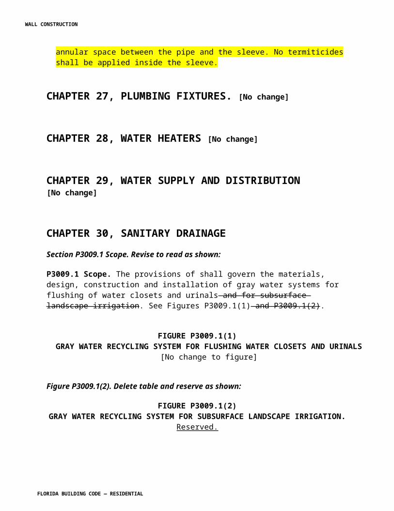
SECTION R4403.2HIGH-VELOCITY HURRICANE ZONES—
DEFLECTION
R4403.2.1 Allowable deflections. The deflection of any structural member or component when subjected to live, wind and other superimposed loads set forth herein shall not exceed the following:
1. Roof and ceiling or components supporting plaster . . . . . . . . . . . . . . . . . . . . . . . . L/3602. Roof members or components not supporting plaster under . . . . . . . . . . . . . . . . . L/2403. Floor members or components . . . . . . . . . . . . . . . . . . . . . . . . . . . . . . . . . . . . . . . L/3604. Vertical members and wall members or components consisting of or supporting
material that hardens in place, is brittle or lacks resistance to cracking caused by bending strains. . . . . . . . . . . . . . . . . . . . . . . . . . . . . . . . . . . . . . . . . . . . . . . . . . . . L/360
5. Vertical members and wall members or components not required to meet the conditions of Section R4403.2.1, Item 4. . . . . . . . . . . . . . . . . . . . . . . . . . . . . . . . . L/180
6. Roof and vertical members, wall members and panels of carports, canopies, marquees, patio covers, utility sheds and similar minor structures not to be considered living areas, where the roof projection is greater than 12 feet (3658 mm) in the direction of the span, for free-standing roofs and roofs supported by existing structures. Existing structures supporting such roofs shall be capable of supporting the additional loading. . . . . . . . . . . . . . . . . . . . . . . . . . . . . . . . . . . . . . L/180
7. For Group R3 occupancies only, roof and vertical members, wall members and panels of carports, canopies, marquees, patio covers, utility sheds and similar minor structures not to be considered living areas, where the roof projection is 12 feet (3638 mm) or less in the direction of the span and for free standing roofs and roofs supported by existing structures. . . . . . . . . . . . . . . . . . . . . . . . . . . . . . . L/80
8. Members supporting screens only. . . . . . . . . . . . . . . . . . . . . . . . . . . . . . . . . . . . . L/809. Storm shutters and fold-down awnings, which in the closed position shall provide a
minimum clear separation from the glass of 1 inch (25 mm) but not to exceed 2 inches (51 mm) when the shutter or awning is at its maximum point of permissible deflection . . . . . . . . . . . . . . . . . . . . . . . . . . . . . . . . . . . . . . . . . . . . . . L/30
10. Roofs and exterior walls of utility sheds having maximum dimensions of 10 feet length, 10 feet width, and 7 feet height. . . . . . . . . . . . . . . . . . . . . . . . . . . . . . . . . . L/80
11. Roofs and exterior walls of storage buildings larger than utility sheds. . . . . . . . . . L/180
SECTION R4403.3HIGH-VELOCITY HURRICANE ZONES—
VOLUME CHANGES R4403.3.1 Volume change. In the design of any building, structure or portion thereof, consideration shall be given to the relief of stresses caused by expansion, contraction and other volume changes.
WALL CONSTRUCTION
FLORIDA BUILDING CODE — RESIDENTIAL
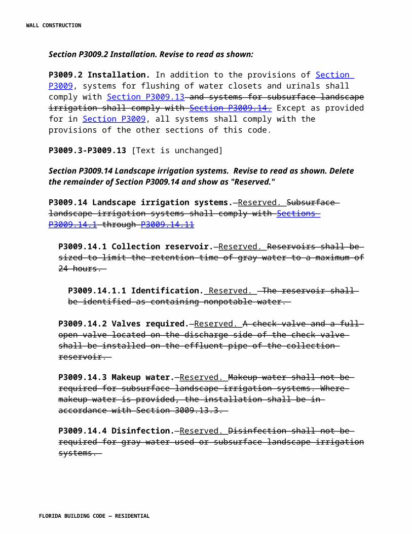
SECTION R4403.6HIGH-VELOCITY HURRICANE ZONES —
ROOF DRAINAGE R4403.6.1 Roof drainage. Where parapets or curbs are constructed above the level of the roof, provision shall be made to prevent rain water from accumulating on the roof in excess of that considered in the design, in the event the rain water drains, conductors or leaders become clogged. R4403.6.2 Where roofs are not designed in accordance with Section R4403.6.1, overflow drains or scuppers shall be placed to prevent an accumulation of more than 5 inches (927 mm) of water on any portion of the roof. In determining the load that could result should the primary drainage system be blocked, the loads caused by the depth of water (i.e., head) needed to cause the water to flow out the scuppers or secondary drainage system shall be included. R4403.6.3 Drains or scuppers installed to provide overflow drainage shall be not less in aggregate area than as shown in Figure R4403.6.3, but not less than 4 inches (102 mm) dimension in any direction and shall be placed in parapets not less than 2 inches (51 mm) nor more than 4 inches (102 mm) above the low point of the finished roofing surface and shall be located as close as practical to required vertical leaders, conductors or downspouts. The roof area to be taken in the sizing of the scuppers is the horizontal projection, except that, where a building wall extends above the roof in such a manner as to drain into the area considered, the one-half of the area of the vertical wall shall be added to the horizontal projection. R4403.6.4 All roofs shall be designed with sufficient slope or camber to assure adequate drainage after the long term deflection from dead load, or shall be designed to support maximum loads including possible ponding of water caused by deflection.
FIGURE R4403.6.3REQUIRED AREA OF OVERFLOW SCUPPERS
R4403.6.5 Ponding loads. Roofs shall be designed to preclude instability from ponding loads. R4403.6.6 Each portion of a roof shall be designed to sustain the loads of all rainwater that could accumulate on it if the primary drainage system for that portion is obstructed. Ponding instability shall be considered in this situation. If the overflow drainage provisions contain drain lines, such lines shall be independent of any primary drain lines.
SECTION R4403.7
HIGH-VELOCITY HURRICANE ZONES — SPECIAL LOAD CONSIDERATIONS
R4403.7.3.6 Railing.
WALL CONSTRUCTION
FLORIDA BUILDING CODE — RESIDENTIAL
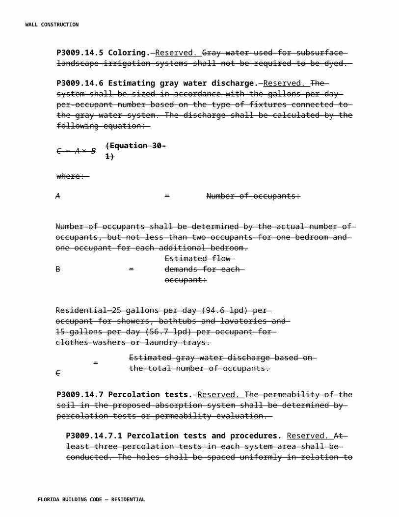
R4403.7.3.6.3 Laminated glazing will be permitted as an equal alternate to pickets, if tested by an accredited laboratory to satisfy the resistance requirements of this code for wind, live and kinetic energy impact loading conditions. The kinetic energy impact loading shall comply with ANSI Z97.1-1984 using a 400 foot-pound (542 N-m) energy impact. The safety requirements of the impact test shall be judged to have been satisfactorily met if breakage does not occur or numerous cracks and fissures occur but no shear or opening through which a 3-inches (76 mm) diameter sphere may freely pass. The glass panel shall remain within the supporting frame. R4403.7.3.6.4 If the posts that support the top rail of exterior railings are substituted with glass, the assembly shall be tested to TAS 201, where the impacted glass continues to support the top rail and all applicable loads after impact. R4403.7.8 Load combination. The safety of structures shall be checked using the provisions of 2.3 and 2.4 of ASCE 7 with commentary. Flood Load Fa mentioned in these load combinations shall be in accordance with Chapter 5 of ASCE 7.Exception: Increases in allowable stress shall be permitted in accordance with TMS 402/ACI 530/ASCE 5 provided the load reduction factor of 0.75 of combinations 4 and 6 of ASCE 7 Section 2.4.1 shall not be applied. SECTION R4403.9HIGH-VELOCITY HURRICANE ZONES — WIND LOADS R4403.9.1 Buildings and structures, and every portion thereof, shall be designed and constructed to meet the requirements of Chapters 26 through 31 of ASCE 7.R4403.9.2 Wind velocity (3-second gust) used in structural calculations shall be 170 miles per hour (76 m/s) in Broward County and 175 miles per hour (79 m/s) in Miami-Dade County. R4403.9.3 All buildings and structures shall be considered to be in Exposure Category C, unless Exposure Category D applies, as defined in Section 26.6 of ASCE 7. R4403.9.4 For wind force calculations, roof live loads shall not be considered to act simultaneously with the wind load. R4403.9.5 Utility sheds shall be designed for a wind load of not less than 15 pounds per square foot (718 Pa). R4403.9.6 The lateral force on rooftop structures and equipment with Af less than (0.1Bh) located on buildings of all heights shall be determined from Eq. 29.5-1 of ASCE 7-10 in which the value of GCf is 3.1. GCf shall be permitted to be reduced linearly from 3.1 to 1.1 as the value of Af is increased from (0.1Bh) to (Bh). The value of G from Section 26.9 of ASCE 7 shall not be used. Additionally, a simultaneous uplift force shall be applied, given by Eq. 29.5-1 of ASCE 7 in which GCf = 1.5 and Af is replaced by the horizontal projected area, Ar, of the rooftop structure or equipment. For the uplift force GCf shall be permitted to be reduced linearly from 1.5 to 1.0 as the value of Ar is increased from (0.1BL) to (BL).
SECTION R4403.10HIGH VELOCITY HURRICANE ZONES —
WALL CONSTRUCTION
FLORIDA BUILDING CODE — RESIDENTIAL
OVERTURNING MOMENT AND UPLIFT R4403.10.1 Computations for overturning moment and uplift shall be based on ASCE 7. R4403.10.2 Overturning and uplift stability of any building, structure or part thereof taken as a whole shall be provided, and be satisfied by conforming to the load combination requirements of ASCE 7.
SECTION R4403.11HIGH-VELOCITY HURRICANE ZONES—
SUNROOMS R4403.11.1 Wind Loads. Basic wind speed in miles per hour (mph) shall be determined in accordance with Section R4403.9.2. Sunrooms including exposed structures, components, cladding, and roof covering shall be designed to resist the wind loads as established in Section R4403.9.R4403.11.2 Sunroom Categories. For the purpose of applying the criteria of the AAMA Standard for sunrooms based on the intended use, sunrooms shall be categorized in one of the following categories by the permit applicant, design professional, or the property owner where the sunroom is being constructed.Category I: A roof or a covering of an outdoor space. The openings shall be permitted to be enclosed with insect screening or 0.5 mm (20 mil) maximum thickness plastic film. The space is defined as non-habitable and unconditioned. Category II: A roof or a covering of an outdoor space with enclosed walls. The openings are permitted to be enclosed with translucent or transparent plastic or glass. The space is defined as non-habitable and unconditioned. Category III: A roof or a covering of an outdoor space with enclosed walls. The openings are permitted to be enclosed with translucent or transparent plastic or glass. The sunroom complies with additional requirements for forced-entry resistance, air-leakage resistance and water-penetration resistance. The space is defined as non-habitable and unconditioned. Category IV: A roof or a covering of an outdoor space with enclosed walls. The sunroom is designed to be heated and/or cooled by a separate temperature control or system and is thermally isolated from the primary structure. The sunroom complies with additional requirements for forced-entry resistance, water penetration resistance, air-leakage resistance, and thermal performance. The space is defined as habitable and conditioned. Category V: A roof or a covering of an outdoor space with enclosed walls. The sunroom is designed to be heated and/or cooled and is open to the main structure. The sunroom complies with additional requirements for forced-entry resistance, water-penetration resistance, air-leakage resistance, and thermal performance. The space is defines as habitable and conditioned.[NOTE: This section has been moved to the Florida Building Code, Building, Section 2003.9.2.][5850 AM R1]
SECTION R4403.12HIGH-VELOCITY HURRICANE ZONES —
SCREEN ENCLOSURES
WALL CONSTRUCTION
FLORIDA BUILDING CODE — RESIDENTIAL
R4403.12.1 Screen enclosures. R4403.12.1.1 The wind loads on screen surfaces shall be per ASCE 7 Figure 29.5-2 based on the ratio of solid to gross area. R4403.12.1.2 Design shall be based on such loads applied horizontally inward and outward to the walls with a shape factor of 1.3 and applied vertically upward and downward on the roof with a shape factor of 0.7. Exception: Screen enclosures shall be permitted to be designed in accordance with the AAF Guide to Aluminum Construction in High Wind Areas. Construction documents based on the AAF Guide to Aluminum Construction in High Wind Areas shall be prepared and signed and sealed by a Florida licensed architect or engineer.R4403.12.2 Windbreakers.R4403.12.2.1 Vinyl and acrylic glazed panels shall be removable. Removable panels shall be identified as removable by a decal. The identification decal shall essentially state "Removable panel SHALL be removed when wind speeds exceed 75 mph (34 m/s)." Decals shall be placed such that the decal is visible when the panel is installed.R4403.12.2.2 Permanent frame shall be designed per Sections R4403.9 and R4403.12.1.2.
SECTION R4403.13HIGH-VELOCITY HURRICANE ZONES—
FLOOD RESISTANCE
R4403.13.1.1 Flood resistance. Where the building or structure is located in a flood hazard areas established in Table 301.2(1), the building or structure, including enclosures below elevated buildings, shall be designed and constructed in accordance with Section R322 and this section. (SP5290 AS)
SECTION R4403.15HIGH-VELOCITY HURRICANE ZONES—
LOAD TESTS R4403.15.1 Application. Whenever there is insufficient evidence of compliance with the provisions of this code or evidence that any material or any construction does not conform to the requirements of this code, or in order to substantiate claims for alternate materials or methods of construction, the building official may require testing by an approved agency, at the expense of the owner or his agent, as proof of his compliance. Testing methods shall be as specified by this code for the specific material. R4403.15.2 Testing method. Such testing shall follow a nationally recognized standard test, or when there is no standard test procedure for the material or assembly in question, the building official shall require that the material or assembly under dead plus live load shall deflect not more than as set forth in Section R4403.2, and that the material or assembly shall sustain dead load plus twice the live load for a period of 24 hours, with a recovery of at least 80 percent or a 100 percent recovery after one-half test load.
WALL CONSTRUCTION
FLORIDA BUILDING CODE — RESIDENTIAL
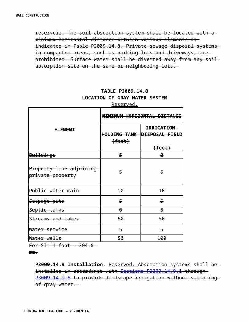
R4403.15.3 Alternate test methods. When elements, assemblies or details of structural members are such that their load-carrying capacity, deformation under load, or deflection cannot be calculated by rational analysis, their structural performance shall be established by test in accordance with test procedures as approved by the building official based on consideration of all probable conditions of loading. R4403.15.4 Fatigue load testing. Where cladding assemblies (including cladding and connections) or roofing framing assemblies (including portions of roof structure and connections) are such that their load-carrying capacity or deformation under load cannot be calculated by rational analysis, the assemblies may be tested to resist the fatigue loading sequence given by Table R4403.15.4
TABLE R4403.15.4FATIGUE LOADING SEQUENCE
RANGE OF TEST NUMBER OF CYCLES10 to 0.5pmax
2 6000 to 0.6max
2 700 to 1.3pmax
2 1
1. Each cycle shall have minimum duration of 1 second and a maximum duration of 3 seconds and must be performed in a continuous manner.2. P max= 0.6 x ultimate design load in accordance with ASCE 7.
Assemblies shall be tested with no resultant failure or distress and shall have a recovery of at least 90 percent over maximum deflection. Any cladding assembly not incorporated into the Florida Building Code, Building after successfully completing the impact test outlined in Section R4403.16, shall be subject to fatigue loading testing and shall obtain Product Approval by the building official.
SECTION R4403.16HIGH-VELOCITY HURRICANE ZONES— IMPACT
TESTS FOR WIND-BORNE DEBRIS R4403.16.1 All parts or systems of a building or structure envelope such as, but not limited, to exterior walls, roof, outside doors, skylights, glazing and glass block shall meet impact test criteria or be protected with an external protection device that meets the impact test criteria. Test procedures to determine resistance to wind-borne debris of wall cladding, outside doors, skylights, glazing, glass block, shutters and any other external protection devices shall be performed in accordance with this section.Exception: The following structures or portion of structures shall not be required to meet the provisions of this section: a. Roof assemblies for screen rooms, porches, canopies, etc., attached to a building that do not breach the exterior wall or building envelope and have no enclosed sides other than screen. b. Soffits, soffit vents and ridge vents. Size and location of such vents shall be detailed by the designer and shall not compromise the integrity of the diaphragm boundary.
WALL CONSTRUCTION
FLORIDA BUILDING CODE — RESIDENTIAL
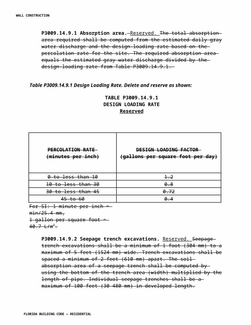
c. Vents in a garage with four or fewer cars. Size and location of such vents shall be detailed by the designer and shall not exceed the minimum required area by more than 25 percent. d. Exterior wall or roof openings for wall or roof mounted HVAC equipment. e. Openings for roof-mounted personnel access roof hatches. f. Storage sheds that are not designed for human habitation and that have a floor area of 720 square feet (67 m2) or less are not required to comply with the mandatory windborne debris impact standards of this code. g. Louvers as long as they properly considered ASCE 7 in the design of the building. h. Buildings and structures for marinas, cabanas, swimming pools and greenhouses.
R4403.16.2 Large missile impact tests. R4403.16.2.1 This test shall be conducted on three test specimens. This test shall be applicable to the construction units, assemblies and materials to be used up to and including 30 feet (9.1 m) in height in any and all structures. R4403.16.2.2 The test specimens shall consist of the entire assembled unit, including frame and anchorage as supplied by the manufacturer for installation in the building, or as set forth in a referenced specification, if applicable. Fasteners used in mounting the test specimen shall be identical in size and spacing to what is used in field installations. R4403.16.2.3 The large missile shall be comprised of a piece of timber having nominal dimensions of 2 inches by 4 inches (51 mm by 102 mm) weighing 9 pounds (4.1 kg). R4403.16.2.4 The large missile shall impact the surface of each test specimen at a speed of 50 feet per second (15.2 m/s). R4403.16.2.5 Each test specimen shall receive two impacts except as noted in Sections R4403.16.2.5.1 and R4403.16.2.5.2, the first within a 5-inch (127 mm) radius circle having its center on the midpoint of the test specimen and the second within a 5-inch (127 mm) radius circle in a corner having its center in a location 6 inches (152 mm) away from any supporting members. R4403.16.2.5.1 For window, glass block, fixed glass and skylight assemblies, both impacts shall be to glass or other glazing infill. For test specimens with more than one light of glass, a single light closest to the center of the assembly shall be selected and impacted twice in accordance with Section R4403.16.2.5. If a light of glass is sufficiently small to cause the 5-inch (127 mm) radius circle to overlap, two separate lights shall be impacted one time each. R4403.16.2.5.1.1 For window, fixed glass and skylight assemblies comprised of different glass thickness, types of glass or different types of glazing infill, each separate thickness or type shall be impacted twice in accordance with Section R4403.16.2.5. R4403.16.2.5.2 For doors, wall cladding and external protection devices, both impacts shall be to the thinnest section through the assembly. For doors, wall cladding and external protection devices with horizontal and/or vertical bracing, both impacts shall be within a single area that is not reinforced and shall be in accordance with Section R4403.16.2.5.
WALL CONSTRUCTION
FLORIDA BUILDING CODE — RESIDENTIAL
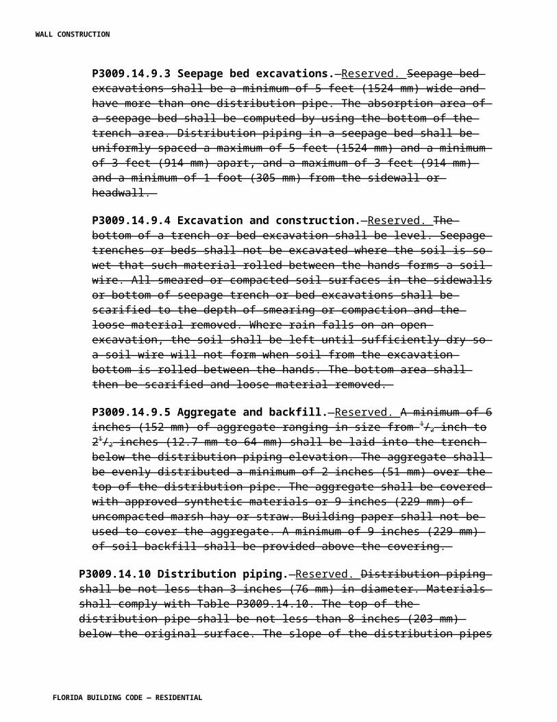
R4403.16.2.5.2.1 For doors with glass, the glass shall be impacted twice and the thinnest section through the assembly that is not glass shall be impacted twice in accordance with Section R4403.16.2.5. R4403.16.2.6 In the case of glazing, if the three test specimens that comprise a test successfully reject the two missile impacts, they shall then be subjected to the cyclic pressure loading defined in Table R4403.16. R4403.16.2.6.1 If external protection devices are employed to protect windows, fixed doors or skylights, they must resist the large missile impacts specified in Sections R4403.16.2.3 and R4403.16.2.4 without deformations which result in contact with the windows, fixed glass, glass block and doors or skylights they are intended to protect. R4403.16.2.6.2 If external protection devices are not designed to be air tight, following the large missile impact test, they must resist an application of force corresponding to those listed in Table R4403.15.4 (fatigue load testing) without detaching from their mountings. The acting pressure cycles shall be simulated with loads applied through a mechanical system attached to the shutter specimen to apply uniformly around the shutter perimeter a force equal to the product of the required pressure and the area of the shutter specimen. R4403.16.2.7 If air leakage through the test specimen is excessive, tape may be used to cover any cracks and joints through which leakage is occurring. Tape shall not be used when there is a probability that it may significantly restrict differential movement between adjoining members. It is also permissible to cover both sides of the entire specimen and mounting panel with a single thickness of polyethylene film no thicker than 0.050 mm (2 mils). The technique of application is important in order that the full load is transferred to the specimen and that the membrane does not prevent movement or failure of the specimen. Apply the film loosely with extra folds of material at each corner and at all offsets and recesses. When the load is applied, there shall be no fillet caused by tightness of plastic film. R4403.16.2.8 A particular system of construction shall be deemed to comply with this recommended practice if three test specimens reject the two missile impacts without penetration and resist the cyclic pressure loading with no crack forming longer than 5 inches (127 mm) and 1/16 inch (1.6 mm) wide through which air can pass. R4403.16.2.9 If only one of the three test specimens in a test fails to meet the above listed criteria, one retest of this system of construction (another test sequence with three specimens) shall be permitted. R4403.16.3 Small missile impact test. R4403.16.3.1 This test shall be conducted on three test specimens. This test shall be applicable to the construction units, assemblies, and materials to be used above 30 feet (9.1 m) in height in any and all structures. R4403.16.3.2 Each test specimen shall consist of the entire assembled unit, including frame and anchorage as supplied by the manufacturer for installation in the building, or as set forth in a
WALL CONSTRUCTION
FLORIDA BUILDING CODE — RESIDENTIAL
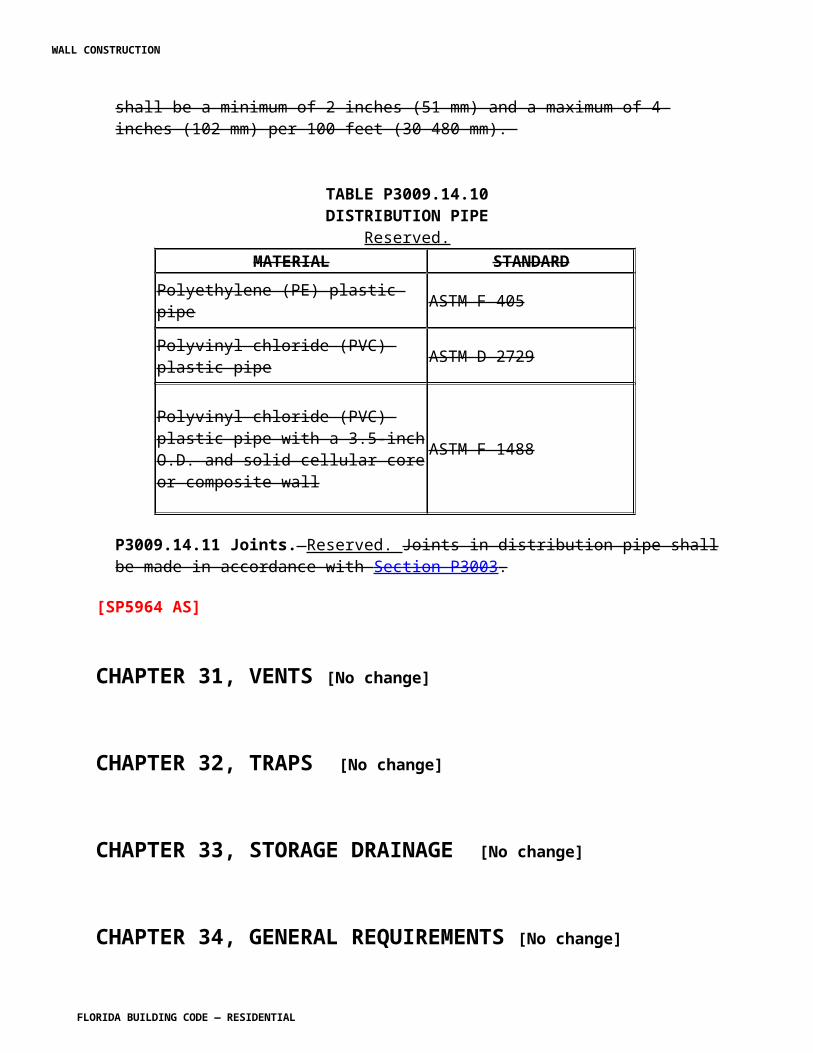
referenced specification, if applicable. The fasteners used in mounting the test specimen shall be identical in size and spacing to those to be used in field installations. R4403.16.3.3 The missiles shall consist of solid steel balls each having a mass of 2 grams (0.07 oz) (+/-5 percent) with a 5/16-inch (7.9 mm) nominal diameter. R4403.16.3.4 Each missile shall impact the surface of each test specimen at a speed of 130 feet per second (40 m/s). R440.16.3.5 Each test specimen shall receive 30 small missile impacts except as noted in Sections R4403.16.3.5.1 and Section R4403.16.3.5.2 delivered in groups of 10 at a time: the first 10 distributed uniformly over a 2-square-foot (0.19 m2) area located at the center of the test specimen, the second 10 distributed uniformly over a 2-square-foot (0.19 m2) area located at the center of the long dimension of the specimen near the edge, and the third 10 distributed uniformly over a 2-square-foot (0.19 m2) area located at a corner of the specimen.R4403.16.3.5.1 For window and skylight assemblies, all impacts shall be to glass or other glazing infill. For test specimens with more than one light of glass, a single light closest to the center of the assembly shall be selected and impacted in accordance with Section R4403.16.3.5. If a light of glass is sufficiently small to cause the 5-inch (127 mm) radius circles to overlap, separate lights may be impacted; however, there must be a total of 30 impacts within the assembly. R4403.16.3.5.1.1 For window, fixed glass and skylight assemblies comprised of glass with different thickness, types of glass or different types of glazing infill, each separate thickness or type shall be impacted in accordance with Section R4403.16.3.5. R4403.16.3.5.2 For doors, wall cladding and external protection devices, all impacts shall be to the thinnest section through the assembly. For doors, wall cladding and external protection devices with horizontal and/or vertical bracing, all impacts shall be within a single area that is not reinforced and shall be impacted in accordance with Section R4403.16.3.5. R4403.16.3.5.2.1 For doors with glass, the glass shall be impacted in accordance with Section R4403.16.3.5 and the thinnest section through the assembly that is not glass shall be impacted in accordance with Section R4403.16.3.5. R4403.16.3.6 In the case of glazing, after completion of the small missile impacts, each test specimen shall then be subjected to the cyclic pressure loading defined in Table R4403.16. R4403.16.3.6.1 If external protection devices are employed to protect windows, doors or skylights, they must resist the small missile impacts specified in Sections R4403.16.3.3 and R4403.16.3.4 without deformations that result in contact with the windows, glass, doors or skylights they are intended to protect. R4403.16.3.6.2 If external protection devices are not designed to be air tight, following the small missile impact test, they must resist an application of force corresponding to those listed in Table R4403.15.4 (fatigue load testing) without detaching from their mountings. The acting pressure cycles shall be simulated with loads applied through a mechanical system attached to the shutter
WALL CONSTRUCTION
FLORIDA BUILDING CODE — RESIDENTIAL
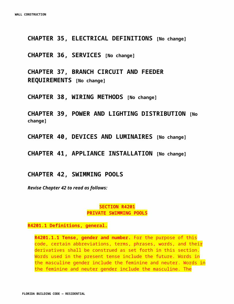
specimen to apply uniformly around the shutter perimeter a force equal to the product of the required pressure and the area of the shutter specimen. R4403.16.3.7 If air leakage through the test specimen is excessive, tape may be used to cover any cracks and joints through which leakage is occurring. Tape shall not be used when there is a probability that it may significantly restrict differential movement between adjoining members. It is also permissible to cover both sides of the entire specimen and mounting panel with a single thickness of polyethylene film no thicker than 0.050 mm (2 mils). The technique of application is important for the full load to be transferred to the specimen and to ensure the membrane does not prevent movement or failure of the specimen. Apply the film loosely with extra folds of material at each corner and at all offsets and recesses. When the load is applied, there shall be no fillet caused by tightness of plastic film. R4403.16.3.8 A particular system of construction shall be deemed to comply with this test if three test specimens reject the small missile impacts without penetration and resist the cyclic pressure loading with no crack forming longer than 5 inches (127 mm) and 1/16 inch (1.6 mm) in width through which air can pass. R4403.16.3.9 If only one of the three test specimens in a test fails to meet the above listed criteria, one retest of the system (another test sequence with three specimens) of construction shall be permitted. R4403.16.4 Construction assemblies deemed to comply with R4403.16. 1. Exterior concrete masonry walls of minimum nominal 8 inch (203 mm) thickness, constructed in accordance with Section R4407 of this code.
2. Exterior frame walls or gable ends constructed in accordance with Section R4408 and Section R4409 of this code, sheathed with a minimum 19/32-inch (15 mm) CD exposure 1 plywood and clad with wire lath and stucco installed in accordance with Section R4411 of this code. 3. Exterior frame walls and roofs constructed in accordance with Section R4408 of this code sheathed with a minimum 24-gauge rib deck type material and clad with an approved wall finish. 4. Exterior reinforced concrete elements constructed of solid normal weight concrete (no voids), designed in accordance with Section R4405 of this code and having a minimum 2 inches (51 mm) thickness. 5. Roof systems constructed in accordance with Section R4408 or Section R4409 of this code, sheathed with a minimum 19/32-inch (15 mm) CD exposure 1 plywood or minimum nominal 1-inch (25 mm) wood decking and surfaced with an approved roof system installed in accordance with Section R4402 of this code.
All connectors shall be specified by the building designer of record for all loads except impact.
TABLE R4403.16CYCLIC WIND PRESSURE LOADING
INWARD ACTING PRESSURE OUTWARD ACTING PRESSURE
WALL CONSTRUCTION
FLORIDA BUILDING CODE — RESIDENTIAL
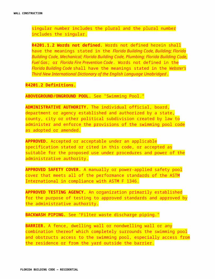
RANGENUMBER OF CYCLES1 RANGE
NUMBER OF CYCLES1
0.2 PMAXto 0.5 PMAX2
3,500 0.3 PMAXto 1.0 PMAX2 50
0.0 PMAXto 0.6 PMAX2
300 0.5 PMAXto 0.8 PMAX2 1,050
0.5 PMAXto 0.8 PMAX2
600 0.0 PMAXto 0.6 PMAX2 50
0.3 PMAXto 1.0 PMAX2
100 0.2 PMAXto 0.5 PMAX2 3,350
Notes:1. Each cycle shall have minimum duration of 1 second and a maximum duration of 3 seconds and must be performed in a continuous manner 1.2. PMAX = 0.6 x ultimate design load in accordance with ASCE 7. The pressure spectrum shall be applied to each test specimen beginning with inward acting pressures followed by the outward acting pressures in the order from the top of each column to the bottom of each column. [S5010-R1 AM]
Section R4404. Change to read as follows:
SECTION R4404HIGH-VELOCITY HURRICANE ZONES —FOUNDATIONS AND RETAINING WALLS
R4404.1 Refer to Chapter 18 of the Florida Building Code, Building .
[S5011 AS]
Section R4405. Change to read as follows:
SECTION R4405HIGH-VELOCITY HURRICANE ZONES —
CONCRETE R4405.1 General Refer to Chapter 19 of the Florida Building Code, Building . R4405.1.1 Scope. This section prescribes requirements for reinforced concrete in construction regulated by this code.
WALL CONSTRUCTION
FLORIDA BUILDING CODE — RESIDENTIAL
R4405.1.2 Application. Reinforced concrete shall be of the materials, proportions strength and consistency as set forth in this section and shall be designed by methods admitting of rational analysis according to established principles of mechanics. R4405.1.3 Requirements. All structures of reinforced concrete, including prestressed concrete, shall be designed and constructed in accordance with the provisions of ACI 318 as adopted herein. R4405.1.4 Workmanship. Concrete construction shall be in conformance with the tolerance, quality and methods of construction set forth in Section R4405.2.
SECTION R4405.2HIGH-VELOCITY HURRICANE ZONES —
STANDARDS R4405.2.1 The following Standards are hereby adopted as part of this code as set forth in Chapter 43 of this code. R4405.2.2 American Concrete Institute (ACI). 1. Standard Tolerances for Concrete Construction and Materials, ACI 117. 2. Specifications for Structural Concrete for Buildings, ACI 301. 3. Manual of Standard Practice for Detailing Reinforced Concrete Structures, ACI 315. 4. Building Code Requirements for Reinforced Concrete, ACI 318. 5. Recommended Practice for Concrete Formwork, ACI 347. 6. Recommended Practice for Shotcreting, ACI 506. 7. Specification for Materials, Proportioning, and Application of Shotcrete, ACI 506.2. 8. Deformed and Plain Billet Steel Bars for Concrete Reinforcement, ASTM A615, including S1. R4405.2.3 American National Standards Institute (ANSI)/American Society of Civil Engineers (ASCE). 1. Specifications for the Design and Construction of Composite Slabs and Commentary on Specifications for the Design and Construction of Composite Slabs, ANSI/ASCE 3. 2. Guideline for Structural Assessment of Existing Buildings, ANSI/ASCE 11. R4405.2.4 American Society for Testing Materials (ASTM). 1. Deformed and Plain Billet Steel Bars for Concrete Reinforcement, ASTM A 615, including.S1. 2. Testing Concrete Aggregates for Use in Construction and Criteria for Laboratory Evaluation, ASTM C 1077.
SECTION R4405.3HIGH-VELOCITY HURRICANE ZONES —
DEFINITIONS
WALL CONSTRUCTION
FLORIDA BUILDING CODE — RESIDENTIAL
R4405.3.1 The following definitions apply to the provisions of Sections 4405.1 through 4405.11. PLAIN CONCRETE. Concrete that is either unreinforced or contains less reinforcement than the minimum amount specified for reinforced concrete. REINFORCED CONCRETE. Concrete reinforced with no less than the minimum amount required by ACI 318, prestressed or non-prestressed, and designed on the assumption that the two materials act together in resisting forces. PRESTRESSED CONCRETE. Reinforced concrete in which internal stresses have been introduced to reduce potential tensile stresses in concrete resulting from loads, The term prestressed concrete refers to pretensioned concrete in which the reinforcing is tensioned before hardening of the concrete, to postensioned concrete in which the reinforcing is tensioned after hardening of the concrete, or combinations of both pretensioning and posttensioning. PRECAST CONCRETE. Plain or reinforced concrete elements cast elsewhere than their final position in a structure. SHOTCRETE. Mortar or concrete pneumatically projected at high velocity onto a surface.
SECTION R4405.4HIGH-VELOCITY HURRICANE ZONES —
MATERIALS
R4405.4.1 Cements. Cements shall conform to one of the following specifications for Portland cement as set forth in Chapter 43. 1. Portland Cement, ASTM C 150 2. Blended Hydraulic Cements, ASTM C 595, excluding Types S and SA, which are not intended as principal cementing constituents of structural concrete. R4405.4.2 Aggregates for concrete shall conform to one of the following specifications as set forth in Chapter 43 of this code or Paragraph R4405.4.2.1. 1. Concrete Aggregates, ASTM C33. 2. Lightweight Aggregates for Structural Concrete, ASTM C330. R4405.4.2.1 Gradation of locally produced sand and crushed rock aggregate shall be as follows:
COARSE AGGREGATE PERCENT PASSING1 ½ -inch sieve 1001-inch sieve 95 - 100
WALL CONSTRUCTION
FLORIDA BUILDING CODE — RESIDENTIAL
½ -inch sieve 25 - 60#4 sieve 0 - 10#8 sieve 0 - 5
FINE AGGREGATE PERCENT PASSING3/8 -inch sieve 100#4 sieve 90 - 100#8 sieve 70 - 95#16 sieve 50 - 85#30 sieve 30 - 70#50 sieve 10 - 45#100 sieve 0 - 10
R4405.4.2.2 Aggregates failing to meet ASTM C 33, ASTM C 330 or the above special gradation but which have been shown by special test or actual service to produce concrete of adequate strength and durability may be used when certified by the engineer. R4405.4.2.3 Aggregates shall be quarried or washed in fresh water and shall contain not more than 1/20 of 1 percent salt by weight. R4405.4.3 Water used in mixing concrete shall be clean and free from injurious amounts of oils, acids, alkalis, salts, organic materials or other substances that may be deleterious to concrete or reinforcement. R4405.4.3.1 Mixing water for concrete, including that portion of mixing water contributed in the form of free moisture on aggregates, shall not contain deleterious amounts of chloride ion. R4405.4.4 Reinforcement. R4405.4.4.1 Deformed reinforcement shall conform to one of the specifications as set forth in Chapter 43, except as provided in Section 3.5 of ACI 318. R4405.4.4.2 Prestressing tendons shall conform to one of the specifications as set forth in Chapter 43. Exception: Wire strands and bars not specifically listed in ASTM A 421, A 416, or A 722 may be used provided they conform to minimum requirements of these specifications and do not have properties that make them less satisfactory than those listed in ASTM A 416, A 421 or A 722. R4405.4.4.3 Reinforcement consisting of structural steel, steel pipe or steel tubing may be used as specified in ACI 318. R4405.4.4.4 All welding of reinforcement shall conform to the Structural Welding Code—Reinforcing Steel , AWS D1.4, as set forth in Chapter 43.
WALL CONSTRUCTION
FLORIDA BUILDING CODE — RESIDENTIAL

R4405.4.4.5 Reinforcement to be welded shall be indicated on the drawings, and welding procedures to be used shall be specified. ASTM steel specifications, except ASTM A 706, shall be supplemented to require a report of material properties necessary to conform to welding procedures specified in AWS D1.4. R4405.4.4.6 Deformed reinforcement may be galvanized or epoxy-coated in accordance with the Specifications for Zinc-Coated (galvanized) Bars for Concrete Reinforcement , ASTM A 767 or the Specification for Epoxy-Coated Bars , ASTM A 775. Zinc or epoxy-coated reinforcement shall conform to ASTM A 615, A 616 (S1), A 617 or A 706. R4405.4.5 Admixtures. R4405.4.5.1 Admixtures to be used in concrete shall conform to one of the specifications set forth in Chapter 43. R4405.4.5.2 An admixture shall be shown capable of maintaining essentially the same composition and performance throughout the work as the product used in establishing concrete proportions. R4405.4.5.3 Admixtures containing chloride ions shall not be used in concrete if their use will produce a deleterious concentration of chloride ion in the mixing water. R4405.4.6 Test of materials. R4405.4.6.1 The building official, or his authorized representative, shall have the right to order the test of any material entering into concrete or reinforced concrete to determine its suitability for the purpose; to order reasonable tests of the concrete from time to time to determine whether the materials and methods in use are such as to produce concrete of the necessary quality; and to order the test under load of any portion of a completed structure when conditions have been such as to leave doubt as to the adequacy of the structure to serve the purpose for which it is intended. R4405.4.6.2 Materials and of concrete shall be tested in accordance with applicable standards of the ASTM International (ASTM) as listed in Chapter 43. Tests shall be made by an approved testing laboratory and results of such tests shall be submitted to the building official. Approved testing laboratories shall comply with ASTM C 1077. R4405.4.6.2 Materials and of concrete shall be tested in accordance with applicable standards of the ASTM International (ASTM) as listed in Chapter 43. Tests shall be made by an approved testing laboratory and results of such tests shall be submitted to the building official. Approved testing laboratories shall comply with ASTM C 1077. R4405.4.6.3 A complete record of tests of materials and of concrete shall be available to the building official for inspection during progress of work and for five years after completion of the project, and shall be preserved by the inspecting engineer or architect for that purpose.
WALL CONSTRUCTION
FLORIDA BUILDING CODE — RESIDENTIAL
R4405.4.6.4 If doubt develops concerning the safety of a structure or member, the building official may order a structural strength investigation by analysis or by means of load tests, or by a combination of analyses and load test as set forth in Chapter 20 of ACI 318.
SECTION R4405.5HIGH VELOCITY HURRICANE ZONES —
CONCRETE QUALITY
R4405.5.1 General. R4405.5.1.1 Concrete shall be proportioned and produced to provide an average compressive strength sufficiently high to minimize the frequency of strength test below the specified compressive strength of concrete, f 'c. R4405.5.1.2 Requirements for f 'c shall be based on tests of cylinders made and tested as prescribed in Section R4405.5.2.2.3. R4405.5.1.3 Unless otherwise specified, f 'c shall be based on 28-day tests. If other than 28-day tests are called for, f 'c shall be indicated in design drawings or specifications. R4405.5.1.4 Design drawings shall show the specified compressive strength of concrete, f 'c for which each part of the structure is designed. R4405.5.2 Evaluation and acceptance concrete. R4405.5.2.1 Frequency of testing. R4405.5.2.1.1 The building official may require a reasonable number of tests to be made during the progress of the work, or may promulgate and set forth in writing such reasonable rules for requiring tests to be made by an approved laboratory as he may consider necessary to insure compliance with this code. R4405.5.2.1.2 Not less than three specimens shall be made for each standard test. R4405.5.2.1.3 Samples for strength of each class of concrete placed each day shall be taken not less than once a day, nor less than once for each 150 cubic yard (4.3 m3) of concrete, nor less than once for each 5,000 square feet (465 m2) of surface area for slabs or walls. R4405.5.2.1.4 On a given project, if total volume of concrete is such that frequency of testing required by Section R4405.5.2.1.1 would provide less than five strength tests for a given class of concrete, tests shall be made from at least five randomly selected batches or from each batch if fewer than five batches are used. R4405.5.2.1.5 Test cylinders taken on truck-mixed concrete shall be taken at the approximate one-quarter point of the load.
WALL CONSTRUCTION
FLORIDA BUILDING CODE — RESIDENTIAL
R4405.5.2.1.6 The age for strength tests shall be 28 days, or where specified, at the earlier age at which the concrete is to receive its full working load. R4405.5.2.2 Laboratory cured specimens. R4405.5.2.2.1 A strength test shall be the average of the strengths of two cylinders made from the same sample of concrete and tested at 28 days or at a test age designated for determination of f 'c. R4405.5.2.2.2 Samples of strength tests shall be taken in accordance with the Method of Sampling Fresh Concrete , ASTM C 172, as set forth in Chapter 43. R4405.5.2.2.3 Cylinders for strength tests shall be molded and laboratory-cured in accordance with the Method of Making and Curing Concrete Test Specimens in the Field , ASTM C 31, as set forth in Chapter 43 of this code, and tested in accordance with the Method of Test for Compressive Strength of Cylindrical Concrete Specimens , ASTM C 39, as set forth in Chapter 43. R4405.05.2.2.4 The strength level of an individual class of concrete shall be considered satisfactory if both of the following requirements are met: 1. Average of all sets of three consecutive strength tests equal or exceed f 'c. 2. No individual strength test (average of two cylinders) falls below f 'c by more than 500 psi (3448 kPa). R4405.5.2.2.5 If any of the requirements of Section R4405.5.2 are not met, steps shall be taken to increase the average of subsequent strength test results. Requirements of Section R4405.5.2.4 shall be observed if any individual strength test falls below f 'c by more than 500 psi (3448 kPa). R4405.5.2.3 Field cured specimens. R4405.5.2.3.1 The building official may require strength tests of cylinders cured under field conditions to check adequacy of curing and protection of concrete in the structure. R4405.5.2.3.2 Field-cured cylinders shall be cured under field conditions in accordance with Section 7.4 of the Method of Making and Curing Concrete Test specimens in the Field, ASTM C 31. R4405.5.2.3.3 Field-cured test cylinders shall be molded at the same time and from the same samples as laboratory-cured test cylinders. R4405.5.2.3.4 Procedures for protecting and curing concrete shall be improved when the strength of field-cured cylinders at test age designated for determination of f 'c is less than 85 percent of that of companion laboratory cured cylinders. The 85 percent may be waived if field cured strength exceeds f 'c by more than 500 psi (3448 Pa).
WALL CONSTRUCTION
FLORIDA BUILDING CODE — RESIDENTIAL
R4405.5.2.4 Investigation of low strength test results. R4405.5.2.4.1 When there is a question as to the quality of the concrete in the structure, the building official may require core tests in accordance with the Standard Method of Obtaining and Testing Drilled Cores and Sawed Beams of Concrete , ASTM C 42, as set forth in Chapter 43 of this code, or order load tests on that portion of the structure where the questionable concrete has been placed. R4405.5.2.4.2 When concrete in structures has failed to meet the minimum standard, the building official shall order analysis and reports by a registered engineer to determine the adequacy of the structure. R4405.5.2.4.3 If the likelihood of low-strength concrete is confirmed and computations indicate that load-carrying capacity may have been significantly reduced, tests of cores drilled from the area in question may be required in accordance with the Method of Obtaining and Testing Drilled Cores and Sawed Beams of Concrete , ASTM C 42, as set forth in Chapter 43 of this code. In such case, three cores shall be taken for each strength test more than 500 psi (3448 kPa) below specified value of f 'c.. R4405.5.2.4.4 If concrete in the structure will be dry under service conditions, cores shall be air dried at a temperature between 60°F and 80°F (16°C and 27°C) and a relative humidity less than 60 percent for seven days before testing and shall be tested dry. If concrete in the structure will be more than superficially wet under service conditions, cores shall be immersed in water for at least 40 hours and be tested wet. R4405.5.2.4.5 Concrete in an area represented by core tests shall be considered structurally adequate if the average of three cores is equals to at least 85 percent of f 'c and if no single core is less than 75 percent of f 'c . To check testing accuracy, locations represented by erratic core strengths may be retested. R4405.5.2.4.6 Slump considerations. The maximum allowable slump of concrete shall be 6 inches (152 mm). On the jobs controlled and supervised by a professional engineer, this maximum may be exceeded, but no concrete shall exceed the slump as indicated on the approved plans for proposed work.
SECTION R4405.6HIGH-VELOCITY HURRICANE ZONES —
MIXING AND PLACING CONCRETE R4405.6.1 Preparation of equipment and place of deposit. R4405.6.1.1 Preparation before concrete placement shall include the following: 1. All equipment for mixing and transporting concrete shall be clean.
WALL CONSTRUCTION
FLORIDA BUILDING CODE — RESIDENTIAL
2. All debris shall be removed from the spaces to be occupied by the concrete. 3. Forms shall be properly coated. 4. Masonry filler units that will be in contact with concrete shall be well drenched. 5. Reinforcement shall be thoroughly cleaned of deleterious coatings. 6. Water shall be removed from place of deposit before concrete is placed unless a tremie is to be used or unless otherwise permitted by the professional engineer. 7. All laitance and other unsound material shall be removed before additional concrete is placed against hardened concrete. R4405.6.2 Mixing. R4405.6.2.1 All concrete shall be mixed until there is uniform distribution of materials and shall be discharged completely before the mixer is recharged. R4405.6.2.2 Ready-mixed concrete shall be mixed and delivered in accordance with requirements of the Specifications for Ready-Mixed Concrete , ASTM C 94, or the Specifications for Concrete made by Volumetric Batching and Continuous Mixing , ASTM C 685, as set forth in Chapter 43 of this code. R4405.6.2.3 Job-mixed concrete shall be mixed in accordance with the following: 1. Mixing shall be done in a batch mixer of approved type. 2. Mixer shall be rotated at a speed recommended by the manufacturer. 3. Mixing shall be continued for at least 11/2 minutes after all materials are in the drum, unless a shorter time is shown to be satisfactory by the mixing uniformity test of Specification for Ready-Mixed Concrete , ASTM C 94. 4. Materials handling, batching, and mixing shall conform to applicable provisions of the Specifications for Ready-Mixed Concrete , ASTM C 94. 5. A detailed record shall be kept to identify: 5.1 Number of batches produced. 5.2 Proportions of materials used. 5.3 Approximate location of final deposit in structure. 5.4 Time and date of mixing and placing. R4405.6.3 Conveying. R4405.6.3.1 Concrete shall be conveyed from mixer to the place of final deposit by methods that will prevent separation or loss of the materials. R4405.6.3.2 Conveying equipment shall be capable of providing a supply of concrete at the site of placement without separation of ingredients and without interruptions sufficient to permit loss of plasticity between successive increments. R4405.6.4 Depositing. R4405.6.4.1 Concrete shall be deposited as nearly as practicable in its final position to avoid segregation caused by re-handling or flowing.
WALL CONSTRUCTION
FLORIDA BUILDING CODE — RESIDENTIAL
R4405.6.4.2 Concreting shall be carried on at such a rate that concrete is at all times plastic and flows readily into the spaces between reinforcement. R4405.6.4.3 Concrete that has partially hardened or been contaminated by foreign materials shall not be deposited in the structure. R4405.6.4.4 Retempered concrete or concrete that has been remixed after initial set shall not be used unless approved by the building official. R4405.6.4.5 After concreting is started, it shall be carried on as a continuous operation until placing of the panel or section, as defined by its boundaries or predetermined joints is completed except as permitted or prohibited by Section R4405.7.4. R4405.6.4.6 Top surfaces of vertically formed lifts shall be generally level. R4405.6.4.7 When construction joints are required, joints shall be made in accordance with Section R4405.7.4. R405.6.4.8 All concrete shall be thoroughly consolidated by suitable means during placement and shall be thoroughly worked around the reinforcement and embedded fixtures and into corners of forms. R4405.6.5 Curing. R4405.6.5.1 Concrete, other than high-early-strength, shall be maintained in a moist condition for at least the first seven days after placement, except when cured in accordance with Section R4405.6.5.3. R4405.6.5.2 High-early-strength concrete shall be maintained in a moist condition for at least the first three days, except when cured in accordance with Section R4405.6.5.3. R4405.6.5.3 Accelerated curing: 1. Curing by high pressure steam, steam at atmospheric pressure, heat and moisture, or other accepted processes, may be employed to accelerate strength gain and reduce time of curing. 2. Accelerated curing shall provide a compressive strength of the concrete at the load stage considered at least equal to required design strength at that load stage. 3. The curing process shall produce concrete with a durability at least equivalent to the curing method of Section R44405.6.5.3, Item 1 or 2. 4. Supplementary strength tests in accordance with Section R4405.5.2.3 may be required to assure that curing is satisfactory. R4405.6.6 Bonding. R4405.6.6.1 Before fresh concrete is deposited or placed on or against concrete which has hardened for 8 hours or longer, the forms shall be retightened, the surface of the hardened
WALL CONSTRUCTION
FLORIDA BUILDING CODE — RESIDENTIAL
concrete shall be cleaned of all foreign matter and laitance, and dampened, but not saturated. Fresh concrete shall not be deposited or placed on or against hardened concrete so dampened before the surface is completely free of shiny spots indicating free moisture. When the concrete against which fresh concrete will be placed is less than 8 hours old, all laitance, loose particles and dirt shall be removed. R4405.6.6.2 Where bonding of fresh to hardened concrete is necessary, construction joints and joints between footings and walls or columns, between walls or columns and beams or floors they support, and joints in unexposed walls shall be accomplished by reinforcement, dowels, adhesives, mechanical connectors or other approved methods. Hardened concrete at joints shall be dampened, but not saturated, immediately prior to the placement of fresh concrete.
SECTION R4405.7HIGH-VELOCITY HURRICANE ZONES —
FORMWORK, EMBEDDED PIPES AND CONSTRUCTION JOINTS R4405.7.1 Design of formwork. R4405.7.1.1 Forms shall be designed in accordance with ACI 347, Recommended Practice for Concrete Formwork . R4405.7.1.2 Forms shall result in a final structure that conforms to shapes, lines and dimensions of the members as required by the design drawings and specifications. R4405.7.1.3 Forms shall be substantial and sufficiently tight to prevent leakage of mortar. R4405.7.1.4 Forms shall be properly braced or tied together to maintain position and shape. R4405.7.1.5 Forms and their supports shall be designed so as not to damage previously placed structures. R4405.7.1.6 Design of formwork shall include consideration of the rate and method of placing concrete; construction loads, including vertical, horizontal and impact loads; and special form requirements for construction of shells, folded plates, domes, architectural concrete or similar types of elements. R4405.7.1.7 Forms for prestressed concrete members shall be designed and constructed to permit movement of the member without damage during application of prestressing force. R4405.7.2 Removal of forms and shores. R4405.7.2.1 No construction loads shall be supported on, nor any shoring removed from, any part of the structure under construction except when that portion of the structure in combination with the remaining forming and shoring system has sufficient strength to safely support its weight and loads placed thereon.
WALL CONSTRUCTION
FLORIDA BUILDING CODE — RESIDENTIAL
R4405.7.2.2 Sufficient strength shall be demonstrated by structural analysis considering proposed loads, strength of the forming and shoring system and concrete strength data. Concrete strength data may be based on tests of field-cured cylinders or, when approved by the building official, on other procedures to evaluate concrete strength. Structural analysis and concrete strength test data shall be furnished to the building official when so required. R4405.7.2.3 No construction loads exceeding the combination of superimposed dead load plus specified live load shall be supported on any unshored portion of the structure under construction, unless analysis indicated adequate strength to support such additional loads. R4405.7.2.4 Forms shall be removed in a manner that does not impair the safety and serviceability of the structure. All concrete to be exposed by form removal shall have sufficient strength not to be damaged thereby. R4405.7.2.5 Form supports for prestressed concrete members may be removed when sufficient prestressing has been applied to enable prestressed members to carry their dead load and anticipated construction loads. R4405.7.3 Conduits and pipes embedded in concrete. R4405.7.3.1 Conduits, pipes and sleeves of any material not harmful to concrete, and with limitations of this section, may be embedded in concrete with approval of the professional engineer provided they are not considered to structurally replace the displaced concrete. R4405.7.3.2 Conduits or pipes of aluminum shall not be embedded in structural concrete unless effectively coated or covered to prevent aluminum-concrete reaction or electrolytic action between aluminum and steel. R4405.7.3.3 Conduits, pipes and sleeves passing through a slab, wall or beam shall not impair the strength of the construction. R4405.7.3.4 Conduits and pipes, with their fittings, embedded within a column shall not displace more than 4 percent of the area of cross section on which strength is calculated or which is required for fire protection. R4405.7.3.5 Except when plans for conduits and pipes are approved by the professional engineer and other than those merely passing through, conduits and pipes embedded within a slab, wall or beam shall satisfy the following: 1. They shall not be larger in outside dimension than three-eighths of the overall thickness of slab, wall or beam in which they are embedded. 2. They shall not be spaced closer than three diameters or widths on center. 3. They shall not impair the strength of the construction. R4405.7.3.6 Conduits, pipes and sleeves may be considered as replacing structurally in compression the displaced concrete, provided:
WALL CONSTRUCTION
FLORIDA BUILDING CODE — RESIDENTIAL
1. They are not exposed to rusting or other deterioration. 2. They are of uncoated or galvanized iron or steel not thinner than standard Schedule 40 steel pipe, and 3. They have a nominal inside diameter not over 2 inches (51 mm) and are spaced not less than three diameters on centers. R4405.7.3.7 In addition to other requirements of Section R4405.7.3 pipes that will contain liquid, gas or vapor may be embedded in structural concrete under the following conditions: 1. Pipes and fittings shall be designed to resist effects of the material, pressure and temperature to which they will be subjected. 2. Temperature of liquid, gas or vapor shall not exceed 150°F (66°C). 3. Maximum pressure to which any piping or fittings shall be subjected shall not exceed 200 psi (1379 kPa) above atmospheric pressure. 4. All piping and fittings except as provided in Section R4405.7.3.5 shall be tested as a unit for leaks before concrete placement. Testing pressure above atmospheric pressure shall be 50 percent in excess of pressure to which piping and fittings may be subjected, but minimum testing pressure shall not be less than 150 psi (1034 kPa) above atmospheric pressure. Pressure test shall be held for 4 hours with no drop in pressure except that which may be caused by air temperature. 5. Drain pipes and other piping designed for pressures of not more than 1 psi (7 kPa) above atmospheric pressure need not be tested as required in Section R4405.7.3.7(4). 6. Pipes carrying liquid, gas or vapor that is explosive or injurious to health shall be tested again as specified in Section R4405.7.3.7(4) after concrete has hardened. 7. No liquid, gas or vapor, except water not exceeding 90°F (32°C) nor 50 psi (350 kPa) pressure, shall be placed in the pipes until the concrete has attained its design strength. 8. In solid slabs the piping, unless it is for radiant heating, shall be placed between top and bottom reinforcement. 9. Concrete cover for pipes and fittings shall not be less than 11/2 inches (38 mm) for concrete exposed to earth or weather, nor 3/4 inch (19 mm) for concrete not exposed to weather or in contact with ground. 10. Reinforcement with an area not less than 0.002 times the area of concrete section shall be provided normal to the piping. 11. Piping and fittings shall be assembled by welding, brazing, solder sweating or other equally satisfactory methods. Screw connections shall not be permitted. Piping shall be so fabricated and installed that cutting, bending or displacement of reinforcement from its proper location will not be required. R4405.7.4 Construction joints. R4405.7.4.1 Surfaces of the concrete construction joints shall be cleaned and laitance removed. R4405.7.4.2 Immediately before new concrete is placed, all construction joints shall be wetted and standing water removed. R4405.7.4.3 Construction joints shall be so made and located as not to impair the strength of the structure. Provision shall be made for transfer of shear and other forces through construction joints.
WALL CONSTRUCTION
FLORIDA BUILDING CODE — RESIDENTIAL
R4405.7.4.4 Construction joints in floors shall be located near the middle of the spans of slabs, beams or girders, unless a beam intersects a girder at the middle location, in which case, joints in the girders shall be offset a distance approximately twice the width of the beam. R4405.7.4.5 Beams, girders or slabs supported by columns or walls shall not be cast or erected until concrete in the vertical support members is no longer plastic. R4405.7.4.6 Beams, girders, haunches, drop panels and capitals shall be placed monolithically as part of a slab system, unless otherwise shown on design drawing.
SECTION R4405.8HIGH-VELOCITY HURRICANE ZONES —
DETAILS OF REINFORCEMENT R4405.8.1 Bending reinforcement. R4405.8.1.1 All reinforcement shall be bent cold, unless otherwise permitted by the professional engineer. R4405.8.1.2 Reinforcement partially embedded in concrete shall not be field bent, except as shown on the design drawings or permitted by the professional engineer. R4405.8.2 Surface conditions of reinforcement. R4405.8.2.1 At the time concrete is placed, reinforcement shall be free from mud, oil or other nonmetallic coatings that adversely affect bonding capacity. R4405.8.2.2 Steel reinforcement, except prestressing tendons, with rust, mill scale or a combination of both shall be considered satisfactory, provided the minimum dimensions, including the height of deformations and weight of a hand-wire-brushed test specimen, are not less than applicable ASTM specification requirements. R4405.8.2.3 Prestressing tendons shall be clean and free of oil, dirt, scale, pitting and excessive ruts. A light oxide is permissible. R4405.8.3 Placing reinforcement. R4405.8.3.1 Steel reinforcement shall be accurately placed and adequately secured in position by concrete or metal chairs or spacers or other acceptable methods. The minimum clear distance between parallel bars, except in columns, shall be equal to the nominal diameter of the bars. In no case shall the clear distance between bars be less than 1 inch (25 mm), or less than one and one-third times the maximum size of the coarse aggregate. When reinforcement in beams or girders is placed in two or more layers, the clear distance between layers shall not be less than 1
WALL CONSTRUCTION
FLORIDA BUILDING CODE — RESIDENTIAL
inch (25 mm) nor less than the diameter of the bars, and the bars in the upper layers shall be placed directly above those in the bottom layer. R4405.8.3.2 Unless otherwise permitted by the building official and professional engineer, reinforcement, prestressing tendons and prestressing ducts shall be placed within the following tolerances: 1. Tolerance for depth, d , and minimum concrete cover in flexural members, walls and compression members shall be as follows, where d represents the distance from the extreme compression fiber to the centroid of the tension reinforcement:
Toleranceon "d"
Tolerance on minimum concrete cover
d < 8 in. +/- 3/8 in. - 3/8 in.d > 8 in. +/- 1/2 in - 1/2 in.
Exceptions: a. Tolerance for the clear distance to formed soffits shall be minus ¼ inch (6.3 mm). b. Tolerance for cover shall not exceed minus one-third the minimum concrete cover required in the contract drawings nor less than 1 inch (25 mm) when exposed to weather. 2. Tolerance for longitudinal location of bends and ends of reinforcement shall be +2 inches (+102 mm) except at discontinuous ends of members where tolerance shall be + ½ inch (+12.7 mm). R4405.8.3.3 Welded wire fabric with a wire size not greater than W5 or D5 used in slabs not exceeding 10 feet (3048 mm) in span may be curved from a point near the top of the slab over the support to a point near the bottom of the slab at midspan, provided such reinforcement is either continuous over, or securely anchored at, the support. R4405.8.3.4 Welding of crossing bars shall not be permitted for assembly of reinforcement unless approved by the professional engineer of record. R4405.8.3.5 Spacing limits and concrete cover for reinforcement shall be shown on the design drawings. R4405.8.4 Splices in reinforcement. R4405.8.4.1 In slabs, beams and girders, splices in reinforcement at points of maximum stress shall be avoided wherever possible. Such splices, where used, shall be welded, lapped or otherwise fully developed, but, in any case, shall transfer the entire stress from bar to bar without exceeding the allowable bond and shear stresses. The minimum overlap for a lapped splice shall be 24 bar diameters, but not less than 12 inches (25 mm) for bars and in accordance with Section
WALL CONSTRUCTION
FLORIDA BUILDING CODE — RESIDENTIAL
12.15 and 12.16 of ACI 318. The clear distance between bars shall also apply to the clear distance from a contact splice and adjacent splices or bars. R4405.8.4.2 Reinforcement shall be spliced only as required or permitted on design drawings, or in specifications or as authorized by the licensed engineer of record. R4405.8.4.3 Lap splices shall not be used for bars larger than #11 except as provided in ACI 318. R4405.8.4.4 Lap splices of bundled bars shall be based on the lap splice length required for individual bars within a bundle, increased 20 percent for a 3-bar bundle and 33 percent for a 4-bar bundle. Individual bar splices within a bundle shall not overlap. R4405.8.4.5 Bars spliced by noncontact lap splices in flexural members shall not be spaced transversely farther apart than one-fifth the required lap splice length, nor 6 inches (152 mm). R4405.8.4.6 Welded splices may be used, provided the metallurgical properties of the bars are suitable as determined by the licensed engineer of record in accordance with AWS D1.4. R4405.8.4.7 End-bearing splices. R4405.8.4.7.1 In bars required for compression only, compressive stress may be transmitted by bearing of square cut ends held in concentric contact by a suitable device. R4405.8.4.7.2 Bar ends shall terminate in flat surfaces within 11/2 degrees of a right angle to the axis of the bars and shall be fitted within 3 degrees of full bearing after assembly. R4405.8.4.7.3 End bearing splices shall be used only in members containing closed ties, closed stirrups, or spirals. R4405.8.4.8 Welded splices in reinforcing bars shall be by certified welders and shall comply with the Standard Structural Welding Code-Reinforcing Steel, AWS D1.4, as set forth in Chapter 43 of this code. R4405.8.5 Concrete protection for reinforcement (non-prestressed). R4405.8.5.1 The reinforcement of footings and other principal structural members in which the concrete is deposited against the ground shall have not less than 3 inches (76 mm) of concrete between it and the ground contact surface. If the concrete surfaces after removal of the forms are to be exposed to the weather or be in contact with the ground, the reinforcement shall be protected with not less than 2 inches (51 mm) of concrete for bars larger than No. 5 and 1 ½ inches (38 mm) for No. 5 bars or smaller except as set forth in Section R4406.8.5.5. R4405.8.5.2 The concrete protective covering for reinforcement at surfaces not exposed directly to the ground or weather shall be not less than 3/4 inch (19 mm) for slabs and wall; and not less than 1 ½ inches (38 mm) for beams, girders and columns. In concrete ribbed floors in which the
WALL CONSTRUCTION
FLORIDA BUILDING CODE — RESIDENTIAL
clear distance between ribs is not more than 30 inches (762 mm), the protection of reinforcement shall be at least 3/4 inch (19 mm). R4405.8.5.3 Concrete protection for reinforcement shall in all cases be as least equal to the diameter of bars except for concrete slabs and joists as set forth herein. R4405.8.5.4 Exposed reinforcement bars intended for bonding with future extensions shall be protected from corrosion by concrete or other adequate covering. R4405.8.5.5 For exterior balcony slabs, slab surface shall be shall be sloped 1/8 unit in 12 units or greater to safeguard against ponding of water and slabs shall be designed and constructed in accordance with the provisions of ACI 318. R4405.8.5.6 Concrete cover for cast-in-place, precast and prestressed concrete shall be in accordance with ACI 318 if not otherwise specified in this section. When this code requires a thickness of cover for fire protection greater than the minimum concrete specified in ACI 318, the greater thickness shall be used. R4405.8.5.7 Exposed reinforcement, inserts and plates intended for bonding with future extensions shall be protected from corrosion.
SECTION R4405.9HIGH-VELOCITY HURRICANE ZONES —
PRECAST CONCRETE UNITS R4405.9.1 General. R4405.9.1.1 Precast concrete units shall comply with the minimum requirements set forth in this section, and the standard set forth in Section R4405.2.3. R4405.8.1.2 All precast concrete elements and their attachments (including embedments) to the main structural frame shall be designed by, and bear the seal of a Florida-registered architect or a Florida-registered engineer, which architect or engineer shall be proficient in structural design. The design shall be based on rational analysis for loads set forth in Section R4403. The architect/engineer of record may delegate this responsibility to a Florida-registered delegated engineer. In that case, shop drawings and design calculations prepared by such delegated engineer shall be reviewed and approved by the architect and the engineer of record. R4405.9.1.3 Only the material cast monolithically with the units at the time of manufacture shall be used in computing stresses unless adequate and approved shear transfer is provided. R4405.9.1.4 The building official may promulgate and set forth in writing such reasonable rules for requiring tests to be made by an approved laboratory as he may consider necessary to insure
WALL CONSTRUCTION
FLORIDA BUILDING CODE — RESIDENTIAL
compliance with this code or uniformity of the products produced. The quantity of tests shall be based on consideration of safety or volume of output. R4405.9.1.5 The building official or his representative shall have free access to the plant of any producer at all hours of normal operation, and failure to permit such access shall be cause for revocation of approval. R4405.9.1.6 Failure of any product to satisfy in every respect the quality prescribed, or failure to conform with plans and specifications, shall be cause for rejection of the products. R4405.9.2 Statements of responsibilities of architects and professional engineers on design of structures using precast concrete components. R4405.9.2.1 The structural construction documents shall indicate the configuration of precast components and shall include details of supports, anchors and connections for those components. Permit documents shall include sufficient details describing the attachment of precast units (including embedments) to the main structure. R4405.9.2.2 The precast permit documents shall bear the signature and seal of the professional architect or engineer charged with the responsibility of the design of the precast units. The architect or engineer of record may delegate this responsibility to a Florida-registered delegated engineer. In that case, shop drawings and design calculations prepared by such delegated engineer shall be reviewed and approved by the architect and/or the engineer of record as an indication that his intent has been understood and that the specified criteria have been used. R4405.9.2.3 The structural submittals shall include component details, calculations and fabrication and erection drawings. All such submittals shall identify the specific project. R4405.9.3 Aggregate. The maximum size of the aggregate for precast units shall be not larger than one-third of the narrowest dimension between sides of the forms of the member in which the unit is cast nor larger than three-fourths of the minimum clear spacing between reinforcing bars and sides of the forms, except that where concrete is placed by means of high frequency vibration, the maximum size of the aggregate shall not be larger than one-half of the narrowest dimension between sides of the form. R4405.9.4 Strength of concrete. R4405.9.4.1 Concrete for precast structural units made of crushed stone or other heavy aggregate shall have a compressive strength of not less than 2,500 psi (17 238 kPa) at 28 days. R4405.9.4.2 Concrete for precast units made of light weight aggregate concrete shall follow the general provisions of Section R4405.1.1.2 with consideration of the nature and limitations of the aggregate and the strength of the product. R4405.9.5 Workmanship.
WALL CONSTRUCTION
FLORIDA BUILDING CODE — RESIDENTIAL
R4405.9.5.1 The mix, the gradation of the aggregate and the workability shall be such as to insure complete filling of the form and continuous intimate bond between the concrete and all steel. R4405.9.5.2 Handling and conveying before curing shall be reduced to a minimum. Machinery for this purpose should be so designed that the unit will not be subject to bending or shock which would produce incipient cracks or broken edges or corners. Precast units shall not be freely transported or placed until the concrete is at least 14 days old, if made with regular cement, or at least seven days old, if made with Type III cement, or until its strength, as established by definite tests, is at least 60 percent of the required 28-day strength. R4405.9.5.3 The use of precast structural units not complying with ACI requirements or having visible cracks, honeycomb, exposed reinforcing except at ends or, with a compressive section dimension more than 1/8 inch (3.1 mm) less than specified dimension shall not be permitted. R4405.9.6 Curing. R4405.9.6.1 No precast structural unit shall be removed from the form until the concrete has attained a compressive strength of 50 percent of the 28-day design strength but not less than 1,250 psi (8619 kPa) as verified by representative tests. R4405.9.6.2 Curing by high pressure steam, steam vapor or other accepted processes may be employed to accelerate the hardening of the concrete and to reduce the time of curing. R4405.9.6.3 To ensure the eventual placement of the units in the structure without damage, the handling shall be done in such a manner that bending shall be reduced to a minimum or prevented. R4405.9.7 Identification and marking. All joists, beams, girders and other units shall show some mark plainly indicating the top of the unit. This mark or symbol shall indicate the manufacturer, the date of manufacture and the length, size and type of reinforcing. R4405.9.8 Cutting of holes. No openings or channels not provided for in the structural design shall be made on the job without the specific approval of the professional engineer in accordance with his written, detailed instructions covering such work. R4405.9.9 Anchorage. Anchorage of all precast concrete units shall be designed, based on rational analysis, to transmit loads and other forces to the structural frame. R4405.9.10 Bridging. Joists shall be secured against lateral displacement by cast-in-place bridging, and such bridging shall be spaced not to exceed 32 times the width of the compression flange of the joist except that for roof systems, cast-in-place Portland-concrete slabs embedding the top flanges not less than ½ inch (13 mm), or steel inserts cast in the joist heads to which bulb-tees supporting gypsum decks are welded, shall be accepted in lieu of bridging.
WALL CONSTRUCTION
FLORIDA BUILDING CODE — RESIDENTIAL
R4405.9.11 Connections. All joints and connections will perform their function at all stages of loading without overstress and with proper safety factors against failure caused by overload. Loading conditions to be considered in the design of joints and connections are service loads, including wind forces, volume changes resulting from shrinkage, creep, and temperature change, reaction loads, and loading encountered in stripping forms, shoring and removal of shores, storage and transportation of members. R4405.9.12 Inspections. R4405.9.12.1 All structural precast units shall be inspected for quality control by an architect or professional engineer qualified to perform these inspections prior to the concrete placement at the casting yard. R4405.9.12.2 All structural precast units and their attachments to the main structure shall be inspected after erection, but before concealment. Such inspections shall be performed by a Florida-registered architect or licensed engineer.
SECTION R4405.10HIGH-VELOCITY HURRICANE ZONES —
PRESTRESSED CONCRETE R4405.10.1 Prestressed concrete, as defined in Section R4405.3, shall comply with this section. R4405.10.1.1 All prestressed structural items shall be designed by a registered licensed engineer. Openings or channels not provided for in the structural design shall not be made on the job without the specific approval of the design licensed engineer. R4405.10.1.2 The building official may promulgate and set forth in writing such reasonable rules for requiring tests to be made by an approved laboratory as he may consider necessary to insure compliance with this code or uniformity of the products produced. R4405.10.1.3 The building official or his or her representative shall have free access to the plant of any producer at all hours of normal operation. Failure to permit such access shall be cause for revocation of approval. R4405.10.1.4 Failure of any product to satisfy the quality prescribed or failure to conform to plans and specifications shall be cause for rejection of the product. R4405.10.2 Statements of responsibilities of architects and professional engineers on design of cast-in-place post-tensioned concrete structural systems. R4405.10.2.1 The structural construction documents shall show the magnitude and location of all prestressing forces and all design assumptions.
WALL CONSTRUCTION
FLORIDA BUILDING CODE — RESIDENTIAL
R4405.10.2.2 The structural engineer of record and/or the architect of record shall require the submission of calculations and installation drawings from a specialty engineer for post-tensioning systems for review by the structural engineer of record and/or the architect of record. Review is an indication that his or her intent has been understood and that the specified criteria have been used. The installation drawings shall provide full details of materials to be used including necessary accessories and instructions for construction and shall identify the specific project and shall bear the impressed seal, signature and date of the specialty engineer who prepared them. R4405.10.2.3 It is the responsibility of the structural engineer of record and/or the architect of record to review the post-tensioning system installation drawings so that the drawings are coordinated with the reinforcing steel shop drawings. R4405.10.2.4 Determining the effect of post-tensioning on other parts of the building is the responsibility of the structural engineer of record and/or the architect of record. R4405.10.3 Design and construction. R4405.10.3.1 Design and construction shall be in accordance with Chapter 18 of ACI 318. R4405.10.3.2 Calcium chloride shall not be used in concrete for prestressed members. R4405.10.4 Tendon and anchorage zones. R4405.10.4.1 Reinforcement shall be provided where required in tendon anchorage zones to resist bursting, splitting, and spalling forces induced by tendon anchorage. Regions of abrupt change in section shall be adequately reinforced. R4405.10.4.2 End blocks shall be provided where required for support bearing or for distribution of concentrated prestressing forces. R4405.10.4.3 Post-tensioning anchorage and supporting concrete shall be designed to resist maximum jacking force for strength of concrete at time of prestressing. R4405.10.4.4 Post-tensioning anchorage zones shall be designed to develop the guaranteed ultimate tensile strength of prestressing tendons using a strength reduction factor of 0.90 for concrete. R4405.10.5 Corrosion protection for unbonded prestressing tendons. R4405.10.5.1 Unbonded tendons shall be completely coated with suitable material to ensure corrosion protection. R4405.10.5.2 Tendon wrapping shall be continuous over the entire length to be unbonded, and shall prevent intrusion of cement paste or loss of coating materials during concrete placement.
WALL CONSTRUCTION
FLORIDA BUILDING CODE — RESIDENTIAL
R4405.10.6 Post-tensioning ducts. R4405.10.6.1 Ducts for grouted or unbonded tendons shall be mortar-tight and nonreactive with concrete, tendons or filler material. R4405.10.6.2 Ducts for grouted single wire, strand or bar tendons shall have an inside diameter at least ¼ inch (6.3 mm) larger than tendon diameter. R4405.10.6.3 Ducts for grouted multiple wire, strand or bar tendons shall have an inside cross-sectional area at least two times the net area of the tendons. R4405.10.7 Grout for prestressing tendons. R4405.10.7.1 Grout shall consist of Portland cement and water; or Portland cement, sand and water. R4405.10.7.2 Materials for grout shall conform as specified in ACI 318 and be as follows: 1. Portland cement. 2. Water content shall be minimum necessary for proper pumping of grout; however, water-cement ratio shall not exceed 0.45 by weight. 3. Sand, if used, shall conform to Standard Specifications for Aggregate for Masonry Mortar , ASTM C 144, except that gradation may be modified as necessary to obtain satisfactory workability. 4. Admixtures conforming to ACI 318 and known to have no injurious effects on grout, steel or concrete may be used. Calcium chloride shall not be used. 5. Water shall not be added to increase grout flow ability that has been decreased by delayed use of grout. 6. Grout temperatures shall not be above 90°F (32°C) during mixing and pumping. R4405.10.8 Protection for prestressing tendons. Burning or welding operations in the vicinity of prestressing tendons shall be carefully performed, so that tendons are not subject to excessive temperatures, welding sparks or ground currents. R4405.10.9 Application and measurement of prestressing force. R4405.10.9.1 Prestressing force shall be determined by both of the following methods and the cause of any difference in force determination that exceeds 5 percent shall be ascertained and corrected. 1. Measurement of tendon elongation. Required elongation shall be determined from average load-elongation curves for prestressing tendons used. 2. Observation of jacking force on a calibrated gauge or load cell or by use of a calibrated dynamometer. R4405.10.9.2 Where transfer of force from bulkheads or pretensioning bed to concrete is accomplished by flame cutting prestressing tendons, cutting points and cutting sequence shall be predetermined to avoid undesired temporary stresses.
WALL CONSTRUCTION
FLORIDA BUILDING CODE — RESIDENTIAL
R4405.10.9.3 Long lengths of exposed pretensioned strand shall be cut near the member to minimize shock to concrete. R4405.10.9.4 Total loss of prestress as a result of un-replaced broken tendons shall not exceed 2 percent of total prestress. R4405.10.10 Post-tensioning anchorages and couplers. R4405.10.10.1 Couplers shall be placed in areas approved by the licensed engineer and enclosed in housing long enough to permit necessary movements. R4405.10.10.2 In unbonded construction subject to repetitive loads, special attention shall be given to the possibility of fatigue in anchorages and couplers. R4405.10.10.3 Anchorage and end fittings shall be permanently protected against corrosion.
SECTION R4405.11HIGH-VELOCITY HURRICANE ZONES —
PNEUMATICALLY PLACED CONCRETE (SHOTCRETE) R4405.11.1 General. R4405.11.1.1 Pneumatically placed concrete is a proportioned combination of fine aggregate Portland cement and water which, after mixing, is pneumatically projected by air directly onto the surface to which it is to be applied. R4405.11.1.2 Pneumatically placed concrete shall conform to all requirements of Specifications for Materials, Proportioning and Application of Shotcrete, ACI 506.2 published by the American Concrete Institute, except as modified herein. R4405.11.1.3 Pneumatically placed concrete shall be composed of Portland cement, aggregate and water proportioned to produce a concrete suitable for pneumatic application. R4405.11.1.4 Concrete ingredients shall be selected and proportioned in a manner that will produce concrete which will be extremely strong, dense and resistant to weathering and abrasion. R4405.11.2 Sampling and testing cement and aggregate. The contractor shall determine the source, kind and quality of the cement and aggregates to be used in the work well in advance of the time scheduled for starting the work and when so directed by the building official shall submit such information for approval before starting shotcrete operation. R4405.11.3 Surface preparation. To ensure adequate bond, the newly chipped and sandblasted surface shall be thoroughly moistened with water prior to application of shotcrete. In no instance shall shotcrete be applied in an area where free running water exists.
WALL CONSTRUCTION
FLORIDA BUILDING CODE — RESIDENTIAL
R4405.11.4 Proportioning. Prior to the start of shotcreting, the contractor shall submit to the licensed engineer the recommended mix as a ratio of cement to aggregate. The recommended mix shall be on the basis of test data from prior experience. R4405.11.5 Mixing. R4405.11.5.1 Shotcrete shall be thoroughly mixed by machine and then passed through a sieve to remove all large particles before placing in the hopper of the cement gun. The mixture shall not be permitted to become damp. Each batch should be entirely discharged before recharging is begun. The mixer should be cleaned thoroughly enough to remove all adherent materials from the mixing vanes and from the drum at regular intervals. R4405.11.5.2 Water in any amount shall not be added to the mix before it enters the cement gun. Quantities of water shall be controlled by a valve at the nozzle of the gun. Water content shall be adjusted as required for proper placement, but shall in no case exceed 4 gallons (15 L) of water per sack of cement, including the water contained in the aggregate. R4405.11.5.3 Remixing or tempering shall not be permitted. Mixed material that has stood 45 minutes without being used shall be discarded. Rebound materials shall not be reused. R4405.11.6 Application. R4405.11.6.1 In shooting walls and columns, application shall begin at the bottom and the first coat shall completely embed the reinforcement to the form. R4405.11.6.2 In shooting beams, application shall begin at the bottom and a surface at right angles to the nozzle shall be maintained. R4405.11.6.3 In shooting slabs, the nozzle shall be held at a slight angle to the work so that rebound is blown on to the finished portion where it shall be removed. R4405.11.6.4 Corners shall be filled first. "Shooting" shall be from an angle as near perpendicular to the surface as practicable, with the nozzle held approximately 3 feet (915 mm) from the work, except in confined control. If the flow of material at the nozzle is not uniform and slugs, sand spots or wet sloughs result, the nozzleman shall direct the nozzle away from the work until the faulty conditions are corrected. Such defects shall be replaced as the work progresses. R4405.11.6.5 Shotcreting shall be suspended if: 1. Air velocity separates the cement from the sand at the nozzle. 2. Temperature approaches freezing and the newly placed shotcrete cannot be protected. R4405.11.6.6 The time interval between successive layers in sloping, vertical or overhanging work must be sufficient to allow initial but not final set to develop. At the time the initial set is developing, the surface shall be cleaned to remove the thin film of laitance in order to provide a good bond with succeeding applications.
WALL CONSTRUCTION
FLORIDA BUILDING CODE — RESIDENTIAL
R4405.11.7 Construction joints. Construction joints or day's work joints shall be sloped off to a thin, clean, regular edge, preferably at a 45 degree (0.78 rad) slope. Before placing the adjoining work, the slope portion and adjacent shotcrete shall be thoroughly cleaned as necessary, then moistened and scoured with an air jet. R4405.11.8 Curing and protection. R4405.11.8.1 Curing shall be in accordance with ACI 506.2 depending upon atmospheric condition. R4405.11.8.2 Immediately after placement, shotcrete shall be maintained in a moist condition for at least the first 24 hours. R4405.11.8.3 Final curing shall continue for seven days after placement if Type I Portland cement is used, or for three days if high-early-strength Type III Portland cement is used, or until the specified strength is attained. Final curing may consist of the initial curing process or an approved moisture-retaining covering. R4405.11.8.4 Natural curing may be used when relative humidity remains above 85 percent when approved by the licensed engineer of record.
SECTION R4405.12HIGH-VELOCITY HURRICANE ZONES —
LIGHTWEIGHT INSULATING CONCRETE FILL R4405.12.1 Lightweight insulating concrete fill. Material produced with or without aggregate additions to Portland cement, water and air to form a hardened material possessing insulating qualities, which, when oven dried shall have a unit weight no greater than 50 pcf (801 kg/m3). R4405.12.1.1 Aggregate lightweight insulating concrete. Insulating concrete fill formulated predominantly with perlite, vermiculite or expanded polystyrene beads. It shall have a minimum compressive strength of 125 psi (861.8 kPa) when tested in compliance with ASTM C 495 and C 796. R4405.12.1.2 Cellular lightweight insulating concrete. Insulating concrete fill formulated by mixing a hydrated cementitious matrix around non-interconnecting air cells created by the addition of foam concentrates formed from hydrolyzed proteins or synthetic surfactants. The cured cellular lightweight insulating concrete shall have minimum compressive strength of 160 psi (1103 kPa) when tested in compliance with ASTM C 495 and C 796. R4405.12.1.3 Cellular/aggregate (Hybrid) lightweight insulating concrete. Insulated concrete fill formulated by combining foam concentrates with low density aggregates to import properties of both aggregate and cellular lightweight insulating fill. It shall have a minimum compressive strength of 200 psi (1379 kPa) when tested in compliance with ASTM C 495 and C 796.
WALL CONSTRUCTION
FLORIDA BUILDING CODE — RESIDENTIAL
R4405.12.1.4 Walkability. A term defining the ability of lightweight insulating fill to withstand anticipated construction traffic during the roof membrane application without significant indentations in the lightweight insulating concrete fill surface. R4405.12.2 Inspection. R4405.12.2.1 Application of all lightweight insulating concrete fill roof decks shall be by applicators approved by the lightweight insulating concrete deck manufacturer. Product Approval shall be required for all lightweight insulation concrete fill systems. R4405.12.2.2 The permit holder shall notify the building official 48 hours prior to the pouring of lightweight insulating concrete fill. R4405.12.2.3 The permit holder shall make available to the building official a job log with the following minimum items. 1. Cast density recordings/hour 2. Product evaluation for application 3. Date and job locations identified 4. Results of any field test conducted. R4405.12.2.4 The building official shall have clear access and clear path at his option for a walkability inspection of lightweight insulating concrete fill 24 hours after placement. R4405.12.3 Testing. The building official may require tests of the lightweight insulating concrete fill to confirm the fastener withdrawal resistance, compressive strength or drainage ability. R4405.12.3.1 Existing roof assemblies to receive lightweight insulating concrete fill other than galvanized G-90 steel deck or structural concrete deck shall be tested for uplift for adhesion to the substrate to confirm compliance with design pressure. R4405.12.4 Materials and limitations of use. Lightweight insulating concrete fill, in conjunction with galvanized formed steel sheets, shall not be used as a roof deck in areas where highly corrosive chemicals are used or stored. R4405.12.4.1 Lightweight insulating concrete fill shall be poured over bottom slotted galvanized (G-90) steel decking as follows; cellular, 0.5 percent open; hybrid, 0.75 percent open, aggregate 1.5 percent open. No lightweight insulating concrete shall be poured over a painted or non-galvanized steel deck. 1. Lightweight insulating concrete fill over structural concrete slabs, twin tees, precast units or other non venting substrates shall be vented, to allow the escape of excess moisture R4405.12.4.2 Minimum thickness of lightweight insulating concrete fill shall be 2 inches (51 mm) over the top plane of the substrate unless otherwise specified in the Product Approval. In all
WALL CONSTRUCTION
FLORIDA BUILDING CODE — RESIDENTIAL
cases, lightweight insulating concrete shall be of sufficient thickness to receive the specific base ply fastener throughout the roof deck. R4405.12.4.3 Minimum compressive strength at 28 days shall be as follows: 1. Aggregate concrete 125 psi (5985 Pa). 2. Cellular type: nailed base sheet 160 psi (7661 Pa). 3. Cellular type: adhered membrane systems 250 psi (11 970 Pa). R4405.12.4.4 Galvanized coatings of formed steel sheets shall be in accordance with ASTM A 525 with a minimum coating designation of G-90. Base steel shall conform to ASTM A 446, grade A, B, C, D or greater and ASTM A 611 C, D or E. R4405.12.4.5 Chemical admixtures shall be in compliance with ASTM C 494. Calcium chloride or any admixture containing chloride salts shall not be used in insulating concrete. Fiber reinforcement may be used to control cracking. Mineral admixtures shall conform to ASTM C 618. R4405.12.4.6 Vermiculite or perlite shall be in compliance with ASTM C 332, Group I. Foam concentrates shall be in compliance with ASTM C 796 and ASTM C 869. R4405.12.4.7 Mixing, placing and finishing shall be in compliance with the deck system Product Approval. Slurry coating, two-density casting and double casting shall be acceptable per the specific manufacturer's recommendations. R4405.12.4.8 If the lightweight insulating concrete deck is to receive Product Approval for a direct-adhered roofing system, the deck surface shall be prepared to the requirements set forth in the roof system Product Approval. R4405.12.4.9 All base ply fasteners for use in lightweight insulating concrete roof decks shall have a Product Approval for use with the specific lightweight insulating concrete roof system in compliance with manufacturer's recommendations and the design pressure of Section R4403. R4405.12.4.10 The lightweight insulating concrete fill fastener withdrawal shall have a minimum resistance for new pours of:1. 60 pounds (267 N) in 28 days when the fastener is installed and allowed to age in the concrete. 2. 40 pounds (178 N) at time of roofing. R4405.12.4.11 Lightweight insulating concrete fill system expansion joint shall be provided at the following locations:1. Where expansion or contraction joints are provided in the structural assembly. 2. Where steel framing, structural steel, or decking change direction. 3. Where separate wings of "L," "U," "T" or similar configurations exist. 4. Where the type of decking changes (for example, where a precast concrete deck and a steel deck abut). 5. Whenever additions are connected to existing buildings.
WALL CONSTRUCTION
FLORIDA BUILDING CODE — RESIDENTIAL
6. At junctions where interior heating conditions change. 7. Wherever differential movement between vertical walls and the roof deck may occur. R4405.12.4.12 Insulation board with lightweight insulating concrete fill shall conform to Type I expanded polystyrene insulation as defined in ASTM C 578. 1. Installation of insulating board in conjunction with lightweight insulating concrete shall comply with uplift requirements set forth in Section R4403. Insulation panels shall be placed in a minimum 1/8 inch (3.2 mm) slurry bed of insulating concrete while the material is still in a plastic state and shall be covered with insulating concrete within the same work day of placement of the insulating panel. The minimum 2 inch (51 mm) continuous pour is required so as not to compromise the diagram design. Insulation panels shall be provided with holes and/or slots for keying and/or slots for venting. R4405.12.4.13 Reinforcing mesh shall be provided when necessary to meet fire-rating and/or special structural design requirements. Refer to a specific Product Approval for the specific requirements applicable to the product being installed.1. Fibers may be added where control of plastic shrinkage and cracking is required. Refer to the Product Approval for the specific requirements applicable to the product being installed. [Mod S5012 AS]
Section R4406. Change to read as follows:
SECTION 4406HIGH-VELOCITY HURRICANE ZONES —
LIGHT METAL ALLOYS
R4406.1 Aluminum. Refer to Chapter 20 of the Florida Building Code, Building .
R4406.1.1 Design. Aluminum members shall be designed by methods admitting of rational analysis according to established principles of mechanics.
R4406.1.2 Standards. The following standards are hereby adopted as set forth in Chapter 463:
1. Specifications for Aluminum Structures, The Aluminum Association, Inc. 2. The Aluminum Formed Sheet Building Sheathing Design Guide, The Aluminum Association, Inc. 3. The Commentary on Specifications for Aluminum Structures, The Aluminum Association, Inc. 4. Engineering Data for Aluminum Structures, The Aluminum Association, Inc. 5. Guidelines for Structural Condition Assessment of Existing Buildings, ANSI/ASCE 11.
R4406.1.3 Workmanship. Aluminum construction shall be in conformance with the tolerances, quality and methods of construction as set forth in Section R4406.1.2 and the American Welding Society's Structural Welding Code-Aluminum (D1.2).
WALL CONSTRUCTION
FLORIDA BUILDING CODE — RESIDENTIAL
R4406.1.6 Allowable unit stresses.
R4406.1.6.1 The design, fabrication and assembly of aluminum members for building and other structures shall conform to the standard set forth in Section R4406.1.2 and as otherwise set forth herein.
R4406.1.6.3 Aluminum members shall be limited by the deflections set forth in Section R4403.2.
R4406.1.7 The building official may require that any structure using aluminum primary or secondary members be designed by a Florida licensed professional engineer.
R4406.1.7.1 Increases in allowable unit stresses as set forth for wind loads in Section R4403.2 shall be applicable to aluminum structural members except that allowable unit stresses thus increased shall not exceed 75 percent of the minimum yield strength.
Exception: No increase in allowable stresses caused by wind loads shall be permitted for aluminum sheet decking, siding and cladding.
R4406.1.7.2 In addition to flexural and shearing stresses, the critical factors of buckling, fatigue, stress raisers such as notches or holes or shape reentrant corners, deflection and connections shall be considered and provided for by proper design.
R4406.1.7.3 All solid roof systems shall be designed for a minimum 30 psf (1436 Pa) live load.
R4406.1.7.4 All buildings and structures shall be designed to resist uplift. In the case of placement on existing slabs and foundations, sufficient information and calculations shall be provided by the professional engineer and/or architect to verify the ability of the slab or foundation to resist uplift loads.
R4406.1.7.5 All connection devices shall be rated by load testing by an approved testing laboratory.
R4406.1.7.5.1 All expansion anchors shall not be installed less than 3 inches (76 mm) from the edge of concrete slab and/or footings. All expansion anchors shall develop an ultimate withdrawal resisting force equal to four times the imposed load, with no stress increase for duration of load.
R4406.1.8 Fabrication and construction details.
R4406.1.8.1 Connections. Aluminum members shall be designed as set forth in the standards in Section R4406.1.2.
R4406.1.8.1.1 Fasteners. Bolts and other fasteners shall be aluminum, stainless steel, hot-dip or electro-galvanized steel. Double cadmium plated steel bolts may also be used.
WALL CONSTRUCTION
FLORIDA BUILDING CODE — RESIDENTIAL
R4406.1.8.1.3 Welding. Aluminum parts shall be welded with an inert-gas-shielded arc or resistance welding process. No welding process that requires a welding flux shall be used. Filler alloys complying with the requirements of the standard in this section shall be used.
R4406.1.8.1.4 Welder qualifications. All welding of structural aluminum member shall be performed by certified welders.
R4406.1.8.1.5 Erection. During erection, structural aluminum shall be adequately braced and fastened to resist dead, wind and erection loads.
R4406.1.8.2 Structural aluminum decking and siding.
R4406.1.8.2.1 Aluminum sections spanning between supports shall be limited in span to satisfactorily support the positive and negative loads set forth in Section R4403.2. The deflection of decking shall not exceed that set forth in Section R4403.2.
R4406.1.8.2.2 Aluminum sheet used for roof decking or siding shall be not less than 0.032 inch (0.8 mm) in thickness.
R4406.1.8.2.3 Aluminum sheets shall be secured to the supports to adequately resist positive and negative loads. Attachments shall be at intervals not exceeding 8 inches (203 mm) o.c. and shall be secured to each other at side laps at intervals as required by rational analysis and/or tests, but shall not exceed 12 inches (305 mm) o.c.
R4406.1.8.2.4 Fasteners shall have a head, and/or be provided with washers not less than 1/2 inch (13 mm) in diameter.
R4406.1.8.2.5 Fasteners located at end laps shall be placed not more than 2 inches (51 mm) nor less than 1 inch (25 mm) from the end of overlapping sheets.
R4406.1.8.2.6 Where roof or wall cladding is of aluminum, an approved membrane to protect against water intrusion to the interior shall be provided or the aluminum cladding shall be designed and constructed with an approved continuous edge-interlock, overlap or seam to prevent water intrusion.
R4406.1.8.3 Nonstructural aluminum decking and siding.
R4406.1.8.3.1 Nonstructural aluminum sheets shall be backed with cladding as set forth in Section R4409 and Section R4410.
R4406.1.8.3.2 Nonstructural aluminum sheets shall have a minimum thickness of 0.032 inches (0.8 mm).
R4406.1.8.3.4 Nonstructural decking and siding shall be attached as set forth in Section R4406.1.8.2 except that the attachment of aluminum residential siding shall be by rational analysis and/or tests using a minimum 0.120-inch (3 mm) diameter aluminum
WALL CONSTRUCTION
FLORIDA BUILDING CODE — RESIDENTIAL
nails of sufficient length to penetrate studs a minimum of 2 inches (51 mm). Nails at wood studs shall be as required by rational analysis and/or tests, but spaced not greater than 24 inches (610 mm) o.c. horizontally and no greater than 8 inches (203 mm) o.c. vertically.
[S5013 AS]
Section R4407. Change to read as follows:
SECTION 4407HIGH-VELOCITY HURRICANE ZONES —
MASONRY
R4407.1 Masonry shall be designed by a method admitting of rational analysis based on established principles of mechanics Refer to Chapter 21 of the Florida Building Code, Building.
SECTION R4407.2HIGH-VELOCITY HURRICANE ZONES —
QUALITY, TESTS, AND APPROVALS
R4407.2.1 Quality. The quality of materials assembled into masonry and the method and manner of their assembly shall conform to the requirements of this section.
R4407.2.1.1 Workmanship. Masonry construction shall be in conformance with the tolerances, quality and methods of construction as set forth in standards referenced in this section; the Portland Cement Association Concrete Masonry Handbook , ANSI A41.1, A41.2 and AWS Structural Welding Code: Reinforcing Steel (D1.4).
R4407.2.1.2 Other materials. A material of masonry, other than set forth herein, which is incombustible and otherwise sufficiently embodies the characteristics and satisfies the requirements of one of the materials herein may be approved by the building official, subject to such tests as may be prescribed.
R4407.2.2 Tests.
R4407.2.2.1 The building official may require materials to be subjected to tests to determine their quality whenever there is reason to believe that a material is no longer up to the standards on which the approval was based. The cost of such tests shall be borne by the person or persons proposing to use or continue to use such material or product.
R4407.2.2.2 Materials shall be tested in accordance with the standard specifications of the ASTM International (ASTM) as such standard specifications are noted in this section.
R4407.2.3 Approvals.
WALL CONSTRUCTION
FLORIDA BUILDING CODE — RESIDENTIAL
R4407.2.3.1 Only such masonry units as bear the approval of the building official and are manufactured or fabricated by plants having a certificate of competency issued by the authority having jurisdiction, shall be considered acceptable for the construction of buildings or other structures.
R4407.2.3.2 Approval of masonry units and manufacturing or fabricating plants shall be for periods not to exceed one year and may be obtained upon application and the submission of certificates of tests in accordance with the provisions of this section.
R4407.2.3.3 The provisions for tests for approval of masonry units shall not be construed as in lieu of any tests otherwise required under this section.
R4407.2.3.4 Failure of a manufacturer of masonry units to obtain approval or to submit tests as required in this section, or such additional tests as the building official may require, shall be cause for rejection of such masonry units.
R4407.2.4 Brick.
R4407.2.4.1 General. Brick shall include masonry units usually 21/4 inches (57 mm) thick, 33/4 inches (95 mm) wide, and 8 inches (203 mm) long, and not less than 75 percent solid.
R4407.2.4.2 Tests. Tests shall be conducted in accordance with Standard Methods of Testing Brick, ASTM C 67.
R4407.2.4.3 Quality.
R4407.2.4.3.1 Burned clay or shale brick shall conform to either the standard Specification for Building Brick (Solid Masonry Units made from Clay or Shale), ASTM C 62, the Standard Specification for Facing Brick (Solid Masonry Units made from Clay or Shale), ASTM C 216 or the Standard Specification for Hollow Brick (Hollow Masonry Units made from Clay or Shale), ASTM C 652.
R4407.2.4.3.2 Sand-lime brick shall conform to the Standard Specification for Concrete Building Brick, ASTM C 55.
R4407.2.4.3.3 Concrete brick shall conform to the Standard Specification for Concrete Building Brick, ASTM C 55.
R4407.2.5 Stone. Stone for masonry shall be hard and durable.
R4407.2.6 Cast stone. Cast stone shall be made of Portland cement, aggregates and water with or without admixtures. Cast stone for load-bearing masonry or where exposed to the weather shall have an average compressive strength, at 28 days, of at least 3,000 psi (20.7 MPa) and shall have not more than 7 percent water absorption by weight.
WALL CONSTRUCTION
FLORIDA BUILDING CODE — RESIDENTIAL
R4407.2.7 Concrete blocks.
R4407.2.7.1 General.
R4407.2.7.1.1 Concrete blocks shall be made of Portland cement, water and approved aggregates. The materials shall conform to the requirements for the materials of concrete specified in Section R4405, and the finished units shall meet the requirements of this section.
R4407.2.7.1.2 Concrete blocks used for fire-resistive walls rated 2 hours or more, or used for load-bearing or exterior walls, shall have a minimum face shell thickness of 11/4 inches (32 mm), a minimum web thickness of 1 inch (25 mm), and shall have a net cross-sectional area not less than 50 percent of the gross section.
R4407.2.7.1.3 Concrete blocks for other purposes shall have wall and web thickness of not less than 3/4 inch (19 mm).
R4407.2.7.1.4 Where masonry walls are required by this code to be 8 inch (203 mm) thickness, hollow concrete blocks units may be 75/8 by 75/8 by 155/8 inches (195 by 195 by 398 mm) modular dimension with corresponding widths for tie columns and tie beams.
R4407.2.7.2 Quality. Standard units of hollow concrete block shall conform to the Standard Specification for Hollow Load-Bearing Concrete Masonry Units, ASTM C 90, except that the maximum moisture content shall not exceed 50 percent of the total absorption.
R4407.2.8 Structural clay tile.
R4407.2.8.1 Limitations. All hollow burned clay wall tile used for fire-resistive walls rated 2 hours or more, load-bearing or exterior walls shall be load-bearing tile.
R4407.2.8.2 Tests. Tests shall be conducted in accordance with the Standard Methods of Sampling and Testing Structural Clay Tile, ASTM C 212.
R4407.2.8.3 Quality.
R4407.2.8.3.1 Structural clay load-bearing wall tile shall conform to the Standard Specification of Structural Clay Load-Bearing Wall Tile, ASTM C 34.
R4407.2.8.3.2 Structural clay floor tile shall conform to the Standard Specification for Structural Clay Floor Tile, ASTM C 57.
R4407.2.8.3.3 Structural clay nonload-bearing tile shall conform to the Standard Specification for Structural Clay Nonload-Bearing Tile, ASTM C 56.
R4407.2.9 Gypsum tile.
R4407.2.9.1 Limitations. Precast gypsum shall not be used in load-bearing masonry or in any
WALL CONSTRUCTION
FLORIDA BUILDING CODE — RESIDENTIAL
masonry that will be exposed to the weather.
R4407.2.9.2 Tests. Tests shall be made in accordance with the Chemical Analysis of Testing Gypsum and Gypsum Products, ASTM C 471, Physical Testing of Gypsum Plasters and Gypsum Cement, ASTM C 472, and Physical Testing of Gypsum Board Products and Gypsum Partition Tile and Block, ASTM C 473.
R4407.2.9.3 Quality. Gypsum partition tile or block shall conform to the Standard Specification for Gypsum Tile or Block, ASTM C 52, Chemical Analysis of Testing Gypsum and Gypsum Products, ASTM C 471, Physical Testing of Gypsum Plasters and Gypsum Cement, ASTM C 472, and Physical Testing of Gypsum Board Products and Partition Tile and Block, ASTM C 473.
R4407.2.10 Plain concrete. Plain concrete is concrete cast in place and not reinforced, or reinforced only for shrinkage or change of temperature. Plain concrete shall be mixed, placed and cured as specified for concrete in Section R4405. The minimum strength of regular concrete shall be not less than 2,000 psi (13.8 MPa) in 28 days. The minimum strength of lightweight aggregate concrete shall be not less than 500 psi (3.5 MPa) in 28 days.
R4407.2.11 Plain gypsum concrete. Plain gypsum concrete is gypsum concrete cast in place and either unreinforced or reinforced for shrinkage.
R4407.2.12 Mortar.
R4407.2.12.1 General. Except as otherwise set forth herein, all mortars and the materials therein shall conform to the Standard Specifications for Mortar of Masonry Units, ASTM C 270.
R4407.2.12.1.1 The gradation of aggregates for masonry mortar shall be such that the fineness modulus is between 1.20 and 2.35 when determined in accordance with the Standard Specifications for Aggregate for Masonry Mortar, ASTM C 144.
R4407.2.12.1.2 Aggregates shall be quarried or washed in fresh water and shall contain not more than 1/20 of 1 percent salt by weight.
MORTAR STRENGTH PROPERTY SPECIFICATIONSType Minimum Average Strength(psi) (MPa)M 2500 (17.2)S 1800 (12.4)N 750 (5.2)O 350 (2.4)
R4407.2.12.1.3 Mortar used to bond unit masonry shall be of Type M, S, N or O and shall comply with either the property specifications set forth hereinafter or the proportion
WALL CONSTRUCTION
FLORIDA BUILDING CODE — RESIDENTIAL
specifications of the standard set forth in R4407.2.12.1.
R4407.2.12.1.4 The type of mortar based on consideration of the location of the unit masonry shall be as follows:
USE OF LOCATION TYPE OF MORTARBelow grade foundations and walls MSwimming pool walls and retaining walls MFire resistive walls rated 2 hours or more M or SExterior walls and load bearing walls M or SPiers less than 32 inches wide M or SPartitions M, S or NSolid masonry units One classification less than that aboveMortar or grout under concentrated loads MFences M, S, N or OGypsum Gypsum
For SI: 1 inch = 25.4 mm.
R4407.2.12.1.5 All solid unit masonry shall be laid in full beds with full end joints. All hollow unit masonry shall be laid with full mortar coverage of the face shells in both horizontal and vertical joints.
SECTION R4407.3HIGH-VELOCITY HURRICANE ZONES —
ALLOWABLE UNIT STRESSES IN UNIT MASONRY
R4407.3.1 Compression.
R4407.3.1.1 Allowable working compressive stresses in masonry walls shall not exceed the limits in pounds per square inch (MPa) of gross area in the following table:
UNIT TYPE N OR O MORTAR TYPE M OR S MORTARBrick 200 (1.4) 300 (2.1)Stone 450 (3.1) 600 (4.1)Rubble Stone 200 (1.4) 300 (2.1)Concrete Blocks 100 (0.7) 150 (1.0)Clay Tile 80 (0.55) 100 (0.7)
R4407.3.1.2 The maximum allowable working stress in plain concrete shall be the following
WALL CONSTRUCTION
FLORIDA BUILDING CODE — RESIDENTIAL
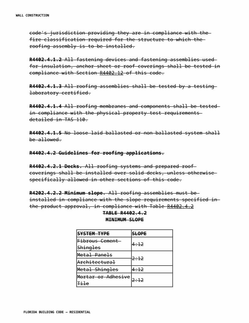
percentage of the ultimate strength of the concrete in compression:
Compression 0.20 f ' c
Shear and diagonal tension 0.02 f ' c
Where f ' c represents the ultimate compressive strength.
R4407.3.2 The shear in unit masonry shall not exceed 1/10 the allowable compressive stress.
R4407.3.3 Un-reinforced unit masonry shall be assumed to have no value in resisting axial tension (uplift). Flexural tension is allowed in unreinforced masonry per ACI 530.
R4407.3.4 Concentrations. Walls of hollow masonry units shall not directly support concentrated loads.
SECTION R4407.4HIGH-VELOCITY HURRICANE ZONES —
CONSTRUCTION DETAILS
R4407.4.1 General.
R4407.4.1.1 Masonry walls of hollow or solid units or plain concrete shall be constructed as specified in this section.
R4407.4.1.2 Designed reinforced concrete walls, columns and beams shall be as specified in Section R4405, except that such designed columns and beams shall be not less than the equivalent of the minimums herein set forth.
R4407.4.1.3 Reinforced concrete required in this section shall comply with Section R4405, Reinforced concrete.
R4407.4.1.4 Second-hand masonry units shall not be used unless they conform to the requirements of this code, are sound and have been thoroughly cleaned and are approved for use by the building official.
R4407.4.1.5 Bond shall be provided by lapping ends in successive vertical courses.
R4407.4.1.6 Minimum No. 9 gauge horizontal joint reinforcing at every alternate course (16 inches spacing), ladder type for reinforced masonry and truss type for all others shall be provided. This reinforcement shall extend 4 inches (102 mm) into tie columns or be tied to structural columns with approved methods where structural columns replace the tie columns.
R4407.4.2 Exterior walls.
WALL CONSTRUCTION
FLORIDA BUILDING CODE — RESIDENTIAL
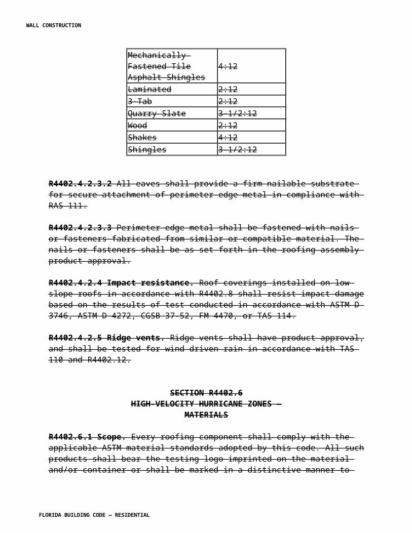
R4407.4.2.1 General.
R4407.4.2.1.1 Exterior walls of unit masonry shall have a minimum thickness of 8 inches (203 mm) except as otherwise set forth in Sections R4407.2.7.1.4 and R4407.4.2.11
R4407.4.2.1.2 No roof or other members shall be placed to develop direct horizontal thrust on walls unless such walls are specifically designed.
R4407.4.2.1.3 The maximum area of wall panels of 8 inch (203 mm) thick unit masonry, as measured between the concrete members which frame the panel such as the beams and tie columns, shall not exceed 240 square feet (22.3 m2), except as set forth in Section R4407.4.2.2.
R4407.4.2.2 Tie columns.
R4407.4.2.2.1 Concrete tie columns shall be required in exterior walls of unit masonry. Concrete tie columns shall be required at all corners, at intervals not to exceed 16 feet (4.9 m) center-to-center of columns, adjacent to any corner opening exceeding 4 feet (1219 mm) in width, and at the ends of free-standing walls exceed 2 feet (610 mm) in length. When openings exceed 8 feet (2.4 m) in width, tie columns shall be provided on each side of all such openings. All gable and shed end corners shall have tie columns.
R4407.4.2.2.2 When openings are between 3 feet and 8 feet (914 mm and 2438 mm) in width, such openings shall have one #5 vertical reinforcing bar at each side. The vertical bars shall be placed in concrete filled cells and shall extend into footings and into tie beams. All such bars shall be continuous from footing to tie beam. All splices, where needed, shall be 30 inches (762 mm) minimum.
R4407.4.2.2.3 Tie columns shall be not less than 12 inches (305 mm) in width. Tie columns having an unbraced height not exceeding 15 feet (4.6 m) shall be not less in thickness than the wall or less than a nominal 8 inches (203 mm), and, where exceeding 15 feet (4.6 m) in unbraced height, shall be not less in thickness than 12 inches (305 mm). The unbraced height shall be taken at the point of positive lateral support in the direction of consideration or the column may be designed to resist applicable lateral loads based on rational analysis.
R4407.4.2.2.4 Tie columns shall be reinforced with not less than four #5 vertical bars for 8 by 12 inch (203 by 305 mm) columns nor less than four #6 vertical bars for 12 by 12 inch (305 by 305 mm) columns nor less reinforcing steel than 0.01 of the cross-sectional area for columns of other dimension nor less than may be required to resist axial loads or bending forces. Vertical reinforcing shall be doweled to the footing and splices shall be lapped 30 bar diameters. Columns shall be tied with #2 hoops spaced not more than 12 inches (305 mm) apart.
R4407.4.2.2.5 The concrete tie columns set forth herein are a minimum to limit masonry panel areas and provide an integrated framework for masonry. The spacing of concrete columns for skeleton frame construction, designed as specified in Section R4405, may exceed the spacing herein set forth provided the masonry panels have an area less than 240 square feet (22.3 m2)
WALL CONSTRUCTION
FLORIDA BUILDING CODE — RESIDENTIAL
and the structural system is designed to transmit horizontal wind loads to the columns.
R4407.4.2.2.6 Concrete tie columns designed to limit masonry panel areas may be offset at tie beams or other horizontal members to avoid openings, but the maximum spacing shall not be exceeded.
R4407.4.2.2.7 Concrete columns in load-bearing walls shall be poured only after masonry units are in place. Where masonry walls of skeleton frame construction are laid up after the frame has been erected, adequate anchorage designed by a professional engineer shall be provided. Where structural steel members are made fire-resistive with masonry units, the panel walls shall be bonded to the fire-resistive materials.
R4407.4.2.2.8 Where the minimum spacing of tie columns, as set forth in Section R4407.4.2.2.1, has been satisfied and where structural columns of skeleton frame construction are spaced as specified in Section R4407.4.2.2.5, provision for resisting the horizontal and vertical loads at the edges of masonry panels abutting door and window openings in masonry walls where openings are not bounded by such reinforced concrete columns shall be considered and, where necessary, transfer the forces through the materials of assembly to the ground.
R4407.4.2.3 Tie beams.
R4407.4.2.3.1 A tie beam of reinforced concrete shall be placed in all walls of unit masonry, at each floor or roof level, and at such intermediate levels as may be required to limit the vertical heights of the masonry units to 16 feet (4.9 m). Well compacted and confined soil below grade may be considered lateral restraint but only above a point 1 foot (305 mm) below the grade where such restraint begins.
R4407.4.2.3.2 Unless otherwise required by design, all tie beams shall have four #3 ties at 12 inches (305 mm) o.c. at corners and at each bend and at 48 inches (1219 mm) o.c. elsewhere. A tie beam shall be not less in dimension or reinforcing than required for the conditions of loading nor less than the following minimums: A tie beam shall have a width of not less than a nominal 8 inches (203 mm), shall have a height of not less than 12 inches (305 mm) and shall be reinforced with not less than four #5 reinforcing bars placed two at the top and two at the bottom of the beam except that a tie beam using "U" type beam block may be used with the following limitations: 1. Limited to one-story Group R3 occupancy. 2. Limited to unsupported spans of 7 feet (2.1 m). 3. Beam block shall be reinforced with one #7 bar in the top and one #7 bar in the bottom of the pour. 4. Beam block shall provide not less than 14 inches (356 mm) vertical dimension or less than 41/2 inches (114 mm) horizontal dimension of poured-in-place beam cross-section. 5. Where beam blocks are used, consideration of resistance to uplift caused by wind forces shall be based on only that portion of the dead load above the topmost mortar joint in the wall.
R4407.4.2.3.3 The tie beam shall be continuous. Continuity of the reinforcing in straight runs
WALL CONSTRUCTION
FLORIDA BUILDING CODE — RESIDENTIAL
shall be provided by lapping splices not less than 30 inches (762 mm). Continuity shall be provided at corners by bending two bars from each direction around the corner 30 inches (762 mm) or by adding two #5 bent bars which extend 30 inches (762 mm) each way from the corner. Continuity at columns shall be provided by continuing horizontal reinforcing through columns or by bending horizontal reinforcing in the columns a distance of 18 inches (457 mm).
R4407.4.2.3.4 A tie beam shall not be required where floor or roof systems provide a rigid diaphragm of reinforced concrete with a minimum thickness of 4 inches (102 mm) or where a floor or roof system has an equivalent stiffness factor of not less than 0.5 cubic inches, as determined by the moment of inertia divided by the length. (Per foot of width, measured normal to the plane of the diaphragm and adequately anchored).
R4407.4.2.3.5 Changes in level of the beams or structural concrete beams (beam) shall be made at tie columns or structural concrete columns and said tie columns or structural concrete columns shall be continuous from beam to beam.
R4407.4.2.3.6 A tie beam may follow the rake of a gable or shed end if the slope does not exceed 3:12 and the requirements of Sections R4407.4.2.1.2 and R4407.4.2.1.3 are met.
R4407.4.2.3.7 The concrete in tie beams shall be placed to bond to the masonry units immediately below and shall not be separated therefrom by wood, felt or any other material which may prevent bond. Felt paper no wider than the width of the cells of the block may be used provided that it is depressed a minimum of 2 inches (51 mm) in one cell of each block.
R4407.4.2.3.8 Tie beams subject to uplift and lateral wind forces shall be sized and designed to resist all such forces. Tie beams over openings shall be sized and designed to resist dead and live loads combined with wind loads, whichever governs.
R4407.4.2.4 Gable end and shed end walls. All masonry structures with gable end and shed end (half gable) walls shall have such end walls constructed of masonry, only in accordance with this section. A horizontal tie beam shall be provided in line with the lower ends of the gables and sheds, except as permitted in Section R4407.4.2.3.6 above, and designed in accordance with Sections R4407.4.2.1.2 and R4407.4.2.1.3, and load requirements as set forth in Section R4403. A concrete coping following the rake of the gable, not less than 64 square inches (413 cm2) in area reinforced with two #5 bars shall be provided. Tie columns at gable and shed ends shall be provided. Any intermediate tie columns required within the gable shall extend to the coping beam. Tie beams resting on masonry which are not subject to uplift and lateral wind forces shall be provided according to Section R4407.4.2.3.2.
R4407.4.2.5 Parapet walls.
R4407.4.2.5.1 Masonry parapet walls shall be not less than 8 inches (203 mm) thick, shall be reinforced with minimum tie columns and shall be coped with a concrete beam not less than 64 square inches (413 cm2) in cross-section, reinforced with two #4 reinforcing bars.
R4407.4.2.5.2 A parapet wall exceeding 5 feet (1524 mm) in height above a tie beam or other
WALL CONSTRUCTION
FLORIDA BUILDING CODE — RESIDENTIAL
point of lateral support shall be specifically designed to resist horizontal wind loads.
R4407.4.2.6 Piers.
R4407.4.2.6.1 In any section of a masonry wall of an enclosed structure where openings are arranged to leave sections of walls less than 16 inches (406 mm), such sections shall be steel or reinforced concrete.
R4407.4.2.6.2 Isolated masonry piers of unenclosed structures shall be so constructed that the height of such piers shall not exceed 10 times the least dimension, that the cells are filled with cement grout and reinforced with not less than two #5 bars anchoring the beam to the foundation.
R4407.4.2.7 Cavity walls.
R4407.4.2.7.1 Cavity walls consisting of two separate walls with an air space of not less than 2 nor more than 6 inches (51 to 152 mm) may be constructed of solid or hollow-unit masonry provided such walls meet the specific requirements for tie columns and beams set forth in this section and are bonded together at intervals not more than 24 inches (610 mm) apart, vertically and horizontally, by masonry ties or by durable, rigid metal ties 0.10 square inch (64.5 mm2) in cross-section.
R4407.4.2.7.2 The minimum thickness of the separate walls of cavity wall construction shall be 4 inches (102 mm), and units shall be laid in full beds of Portland cement mortar with full-end joints.
R4407.4.2.8 Brick and stone walls. Walls of brick and stone shall be laterally supported by tie columns and beams, or the equivalent thereof, as provided in this section and shall meet these additional requirements: 1. In all brick walls at least every sixth course on both sides of the wall shall be a header course or there shall be at least one full header in every 72 square inches (465 cm2) of each wall surface. 2. In walls more than 12 inches (305 mm) thick, the inner joints of header courses shall be covered with another header course that shall break joints with the course below. 3. Solid-unit masonry shall comply with the standard Building Code Requirements for Masonry, ANSI A41.1. 4. Rubble stone walls shall be 4 inches (102 mm) thicker than is required for solid brick or concrete walls of the same respective heights, but in no part less than 16 inches (406 mm).
R4407.4.2.9 Substitutions.
R4407.4.2.9.1 Where, for architectural reasons or otherwise, it is desirable to reduce the area of any required tie column or tie beam below the specified requirements, the building official may grant such reduction, provided that the area of concrete omitted shall be replaced by reinforcing or structural steel in the ratio 1:(n-1) where "n" is defined as the Modular Ratio of Elasticity
WALL CONSTRUCTION
FLORIDA BUILDING CODE — RESIDENTIAL
(Esteel/Econcrete).
R4407.4.2.9.2 Where it is desired to substitute for the #5 reinforcing as required by this section, three #4 bars may be substituted to replace two #5 bars.
R4407.4.2.10 Wall additions. Where new walls are connected to existing walls, such connection shall be by means of a starter column of minimum 8 by 8 inches (203 by 203 mm) dimension reinforced with two #5 bars.
R4407.4.2.11 Chases, recesses and openings.
R4407.4.2.11.1 Unit masonry walls required to be a minimum of 8 inches (203 mm) thick, such as exterior walls, fire walls and bearing walls, may be chased or recessed not deeper than one-half the wall thickness for an area not exceeding 8 square feet (0.74 m2), provided the horizontal dimension of the chase or recess does not exceed 4 feet (1219 mm) and provided the chasing shall not reduce the dimension of tie beams and tie columns to less than herein required, except as follows:
Exception: Four-inch (102 mm) deep chases or recesses in 8 inch (703 mm) unit masonry walls may be constructed with 4-inch (102 mm) unit masonry panels provided such - inch (102 mm) unit masonry panel does not exceed 5 feet (1524 mm) in width, does not exceed 8 feet (2.4 m) in height, is bonded on one vertical side to 8 inch (203 mm) masonry or a tie column, and is not load bearing. Where such panel exceeds 2 feet (610 mm) in width at locations 20 feet (6.1 m) or more above grade in exterior walls, resistance to wind load shall be considered in the design, and a minimum of 4-inch by 8-inch (102 mm by 203 mm) tie column with two #5 vertical bars shall be provided in the free standing end of such 4-inch (102 mm) wall.
R4407.4.2.11.2 Openings shall have lintels of reinforced concrete. Where such lintel is precast or formed separately from a tie beam, it shall bear not less than nominal 8 inches (203 mm) on the masonry, at each end except as may otherwise be approved for compliance with this code by Product Approval, or after rational analysis, but not less than 4 inches (102 mm). Where such lintel is formed integrally with the tie beam by deepening the tie beam above the opening, and the tie beam itself is capable of safely supporting all loads, the beam may span up to 6 feet (1.8 m) in length and may be deepened not to exceed 8 inches (203 mm) without additional reinforcing. Where the tie beam is deepened in excess of 8 inches (203 mm) with a span less than 6 feet (1.8 m) in length, and the tie beam itself is capable of supporting all loads, the dropped portion shall contain a #3 horizontal bar at the bottom, bent up at each end and fastened to the upper tie beam steel or two #4 horizontal bars. The dropped portion shall bear at least 4 inches (102 mm) on the masonry at each end. Where the span is in excess of 6 feet (1.8 m), the principal beam reinforcing shall be at the bottom of the beam.
R4407.4.2.12 Glass block.
R4407.4.2.12.1 Masonry of glass unit masonry may be used in nonload-bearing exterior or interior walls and in openings which might otherwise be filled with windows, either isolated or in continuous bands, provided the glass unit masonry panels have a thickness of not less than
WALL CONSTRUCTION
FLORIDA BUILDING CODE — RESIDENTIAL
31/2 inches (89 mm) at the mortar joint and the mortared surfaces of the units are satisfactorily treated for mortar bonding.
R4407.4.2.12.2 Glass unit masonry panels for exterior walls shall have a Product Approval.
R4407.4.2.12.3 Exterior unit masonry panels shall be set in recesses at the jambs and, for panels exceeding 10 feet (3 m) in horizontal dimension between supports, at the head as well, to provide a bearing surface at least 1 inch (25 mm) wide along the panel edges; except that when approved by the building official for panels exceeding neither 100 square feet (9.3.m2) in area nor 10 feet (3 m) in either horizontal or vertical dimension, and situated four stories or less, and less than 52 feet (15.8 m) above grade level, anchorage may be provided by means of non - corrodible perforated metal strips.
R4407.4.2.12.4 Glass unit masonry panels shall have reinforcement in the mortar joints spaced not more than 2 feet (610 mm) apart vertically and below and above any openings within a pane. The reinforcement shall consist of two parallel longitudinal galvanized steel wires, No. 9 gauge or larger, spaced 2 inches (51 mm) apart, and welded to No. 14 or heavier cross wires at intervals not exceeding 8 inches (203 mm), or the equivalent approved by the building official.
R4407.4.2.12.5 Glass unit masonry shall be laid in only Type M or S mortar or equivalent approved material. Both vertical and horizontal mortar joints shall be at least 1/4 inch (6 mm) and not more than 3/8 inch (9.5 mm) thick and shall be completely filled.
R4407.4.2.12.6 Every exterior glass unit masonry panel shall be provided with expansion joints at the sides and top. Expansion joints shall be entirely free of mortar, and shall be filled with resilient material.
R4407.4.2.12.7 Glass masonry units required to provide a fire resistance rating shall comply with Section R4407.4.1.12.8 or shall be fire tested and listed for their intended use.
R4407.4.2.12.8 View panels in 1-hour fire-resistant walls shall be limited to glass unit masonry panels installed in steel channels, or panel anchor framing may be used where a 3/4-hour fire rating is required. Three and seven-eighths inch (98 mm) thick glass masonry unit shall be limited to 120 square feet (1.1 m2) with no dimension greater than 12 feet (3.7 m) for masonry wall construction or to 94 square feet (8.7 m2) with no dimension greater than 10.75 feet (3.3 m) for non-masonry wall construction. Three and one-eighths inch (79 mm) thick glass masonry units shall be limited to 100 square feet (9.3 m2) with no dimension greater than 10 feet (3 m) for masonry wall construction or to 94 square feet (8.7 m2) with no dimension greater than 10.75 feet (3.3 m) for non-masonry wall construction. Three inches (76 mm) thick glass masonry units shall be limited to 100 square feet (9.3 m2) with no dimension greater than 12 feet (3.7 m) for masonry wall construction or to 94 square feet (8.7 m2) with no dimension greater than 10 feet (3 m) for non-masonry wall construction.
View panels in 2-hour fire resistant walls shall be limited to glass masonry units installed in steel channels and with a water curtain in conformance with NFPA 13 on each side at interior walls or at the interior of exterior walls. Three and seven-eighths inch (98 mm) thick glass
WALL CONSTRUCTION
FLORIDA BUILDING CODE — RESIDENTIAL
masonry units shall be limited to 100 square feet (9.3 m2) with no dimension greater than 10 feet (3 m).
The view panel assembly shall not exceed 25 percent of the wall separating a tenancy from a corridor or a corridor from an enclosed vertical opening or one fire-rated area from another fire-rated area.
Maximum 3/4-hour fire-rated glass masonry units construction shall be used at non-masonry wall construction. Panel anchors shall be provided at sill and jambs in non-masonry wall construction using panel anchor framing. A fire retardant sealant shall be used at all channel and panel anchor framing. Expansion material at heads and jambs shall be either fibrous glass or mineral wool. All fire rated glass masonry units and panels shall conform to UL No. 9 and ASTM E 163.
R4407.4.2.12.9 Interior glass masonry unit panels having thickness of 37/8 inches (98 mm) shall not exceed 250 square feet (23.2 m2) of unsupported wall surface and interior glass masonry unit panels having thickness of 31/8 inches (79 mm) shall not exceed 150 square feet (13.9 m2) of unsupported wall surface nor more than 25 feet (7.6 m) in length nor more than 20 feet (6.1 m) in height between supports.
R4407.4.2.13 Grill block.
R4407.4.2.13.1 Decorative grills or screens constructed of unit masonry laid with cells open through the wall shall be as set forth herein or designs shall be based on rational analysis to resist applicable loads and computations shall be submitted to the building official for approval.
R4407.4.2.13.2 Unit masonry grills or screens as described in this paragraph shall not be load bearing.
R4407.4.2.13.3 Unit masonry in exterior wall shall be laid in Type M or S mortar.
R4407.4.3 Interior bearing walls. Interior-bearing walls shall be constructed as specified in Section R4407.4.2 for exterior walls, except that interior bearing walls in one-story building of Group H or I occupancy, where not required to be more than 1-hour fire-resistive, may be constructed of 4 inch (162 mm) concrete block not exceeding 9 feet (2.7 m) in height, capped with a reinforced concrete beam not less than 4 inches (102 mm) in width nor less than 12 inches (305 mm) in height, reinforced with two 1/2-inch rods (12.7 mm), and such walls shall support only a roof or ceiling not in excess of 700 pounds per lineal foot (10.2 kN/m) with no chases or recesses.
R4407.4.5 Panel walls.
R4407.4.5.1 Panel walls of unit-masonry shall be not less than 8 inches (203 mm) thick and shall be limited in panel dimension as set forth in Section R4407.4.2.
R4407.4.5.2 Panel walls of reinforced concrete shall be not less than 4 inches (102 mm) thick
WALL CONSTRUCTION
FLORIDA BUILDING CODE — RESIDENTIAL
nor less than required by design as specified in Section R4405.
R4407.4.6 Veneered walls.
R4407.4.6.1 Masonry backing.
R4407.4.6.1.1 Veneering or facing on masonry backing shall not be considered as adding any strength to such walls and shall be limited in height above foundations or between proper and adequate supports to 30 feet (9.1 m). Veneering shall be securely anchored to masonry backing by means of substantial, non-corroding metal wall ties, spaced not farther apart than 16 inches (406 mm) vertically or 24 inches (610 mm) horizontally.
R4407.4.6.1.2 Tile veneering, not more than 1 inch (25 mm) thick with individual units not exceeding 20 inches (508 mm) in any dimension and having not more than 200 square inches (1290 cm2) of surface area with corrugations or scoring on the back side thereof, need not be anchored in accordance with the above requirements but shall be cemented solid to the backing with Portland cement mortar so as to provide a continuous integral support to the backing.
R4407.4.6.2 Wood backing.
R4407.4.6.2.1 In all cases, before applying masonry veneer, a substantial waterproofed paper or asphalt-saturated felt, weighing not less than 14 pounds per 100 square feet (0.68 kg/m2) shall be applied horizontally, shingle fashion, over diagonal sheathing. Horizontal joints in the paper or felt shall be lapped not less than 4 inches (102 mm) and vertical end joints not less than 6 inches (152 mm).
R4407.4.6.2.2 Masonry veneer shall be not less than 33/4 inches (95 mm) thick and shall be bonded to the backing by means of substantial non-corroding metal wall ties spaced not farther apart than 16 inches (406 mm) vertically and 24 inches (610 mm) horizontally.
R4407.4.8 Fences.
R4407.4.8.1 Masonry fences so located on a property that such fence, at the proposed height or by a future addition to height, could be used as a wall of a building shall be constructed with foundations and tie columns as provided for an exterior wall. Such fence shall be capped with a coping beam not less than 64 square inches (413 cm2) in cross-section reinforced with a minimum of two #4 rods, when not exceeding a height of 5 feet (1.5 m), or shall be capped by a tie beam as provided for exterior walls if exceeding a height of 5 feet (1.5 m).
R4407.4.8.2 Masonry fences, so located on a property that by zoning regulation such fence could not be used as a wall of a building, shall be constructed as follows:
R4407.4.8.2.1 Fences not exceeding 5 feet (1.5 m) in height shall be 8 inches (203 mm) thick and shall not be required to have tie columns, but shall be required to have a coping as provided herein; or such fences may be 4 inches (102 mm) thick with tie columns and coping not less than 8 inches (203 mm) thick.
WALL CONSTRUCTION
FLORIDA BUILDING CODE — RESIDENTIAL
R4407.4.8.2.2 Fences exceeding 5 feet (1.5 m) in height shall be not less than 8 inches (203 mm) thick and shall have tie columns and tie beams as required for exterior walls.
R4407.4.9 Other masonry walls. Walls of masonry materials or arrangements of masonry units other than those specifically set forth in this section shall be in conformance with the general provisions of this code, may be classified by the subject to all or any of the requirements therefor to and any such additional requirements as the building official may prescribe.
SECTION R4407.5HIGH-VELOCITY HURRICANE ZONES —
REINFORCED UNIT MASONRY
R4407.5.1 Standards. The provisions of TMS 402/ACI 530/ASCE 5, and TMS 602/ACI 530.1/ASCE6 are hereby adopted as a minimum for the design and construction of reinforced unit masonry. In addition to TMS 402/ ACI 530/ ASCE 5 and TMS 602/ACI 530.1/ASCE6 reinforced unit masonry structures shall comply with Sections R4407.2 Exception: Unless otherwise specified by the designing architect or engineer, where plan review and inspections are performed by a local building department in accordance with Sections 106 and 109, the provisions of TMS 402/ ACI 530/ASCE 5/TMS 402, Chapter 1, Section 1.18 and TMS 602/ ACI 530.1/ASCE 6/ Sections 1.5 and 1.6 shall not apply.R4407.5.2 General. Reserved.R4407.5.3 The design of buildings and structures of reinforced unit masonry shall be by a professional engineer or registered architect. R4407.5.4 Special inspector. A Florida-registered architect or professional engineer shall furnish inspection of all reinforced unit masonry structures. R4407.5.5 Concrete masonry strength. Concrete masonry strength shall be determined by unit strength method from TMS 602/ACI 530.1/ ASCE 6 Section 1.4 or in accordance with ASTM C 1314. R4407.5.6. Reinforcement. Reinforcement shall comply with TMS 402/ACI 530/ ASCE 5 and TMS 602/ ACI 530.1/ ASCE 6 except as modified herein.R4407.5.6.1 Development of bars in tension and compression shall be in accordance with TMS 402/ASCE 530/ ASCE5 Section 2.1.9.3 with the following changes to the factor y of Equation 2-12. y = 1.0 for No. 3 (M#10) through No. 5 (M#16) bars;y = 1.04 for No. 6 (M#19) through No. 7 (M#22) bars; andy = 1.2 for No. 8 (M#25) through No. 11 (M#36) bars Where epoxy coated bars are used, lap length shall be increased by 50 percent.R4407.5.6.2 Splices of reinforcement shall be in accordance with TMS 402/ ACI 530/ ASCE 5. Lap splices, welded splices, or mechanical splices are permitted in accordance with the provisions of TMS 402/ ACI 530/ ASCE 5 Section 2.1.9.7. Welding shall conform to AWS D1.4. R4407.5.6.3 Lap splices shall be in accordance with TMS 402/ ACI 530/ ASCE 5, Section 2.1.9.7.1.1 with the modifications of Section 2122.4.1 to the factor y of Equation 2-12. In no
WALL CONSTRUCTION
FLORIDA BUILDING CODE — RESIDENTIAL
case shall the length of the lapped splice be less than 48 bar diameters, but not less than 12 inches. R4407.5.6.4 Joint reinforcement. Horizontal joint reinforcement shall be provided at every other course. Joint reinforcement shall be a minimum of No. 9 gauge and shall comply with TMS 602/ACI 530.1/ ASCE 6 Sections 2.4C through 2.4F. Joint reinforcement shall be placed in accordance with TMS 602/ACI 530.1/ ASCE 6 Section 3.4 B.7. R4407.5.7 Concentrated loads shall be in accordance with TMS 402/ ACI 530/ ASCE 5 Sections 1.9.7.2 and 2.1.8 and shall not be assumed distributed across continuous vertical joints, including stack bond joints, unless reinforcing elements are designed and provided to distribute such loads.R4407.5.8 Reinforced masonry bearing walls shall have a nominal thickness of not less than 8 inches (203 mm).R4407.5.9 Anchorage requirements. Anchorage shall be in accordance with TMS 402/ ACI 530/ ASCE 5. Loading shall comply with TMS 402/ ACI 530/ ASCE 5 Section 1.7 and the following. R4407.5.9.1 Reinforced masonry walls shall be securely anchored to adjacent structural members such as roofs, floors, columns, pilasters, buttresses and intersection walls. R4407.5.9.2 Masonry walls shall be anchored to all floors and roofs that provide lateral support to such walls. R4407.5.9.3 Such anchorage shall provide a positive direct connection capable of resisting the horizontal forces as required in Chapter 16 (High-Velocity Hurricane Zones), or a minimum force of 200 pounds per lineal foot (2919 N/m) of wall, whichever is greater. R4407.5.9.4 Required anchors shall be embedded in reinforced grouted cells. Anchor bolts shall be installed in accordance with TMS 602/ ACI 530.1/ ASCE 6 Section 3.4 D R4407.5.9.5 Wood framing connected by nails shall not be considered as acceptable anchorage. R4407.5.10 Mortar and grout. R4407.5.10.1 Mortar materials shall comply with TMS 602/ ACI 530.1/ ASCE 6 Section 2.1. Grout materials shall comply with TMS 602/ ACI 530.1/ ASCE 6 Section 2.2. R4407.5.10.2 Vertical cells to be grouted shall provide vertical alignment sufficient to maintain clear, unobstructed, continuous, vertical cores measuring not less than 2 ½ inches by 3 inches (51 mm by 76 mm) for fine aggregate grout and 3 inches by 3 inches for coarse aggregate grout as defined by ASTM C 476. The architect or engineer may specify other grout space sizes shall be permitted provided they comply with TMS 402/ ACI 530/ ASCE 5 Section 1.19 and TMS 602/ ACI 530.1/ ASCE 6 Section 3.5C. R4407.5.10.3 Placing of mortar and masonry units shall comply with TMS 602/ ACI 530.1/ ASCE 6 Section 3.3. R4407.5.10.4 Grout placement. Grout placement shall be in accordance with TMS 402/ ACI 530/ ASCE 5 and TMS 602/ ACI 530.1/ ASCE 6. R4407.5.10.5 Confinement. Confine grout to the areas indicated on the Project Drawings. Use material to confine grout that permits bond between masonry units and mortar. R4407.5.10.6 Unless otherwise required, mix grout other than self-consolidating grout to a consistency that has a slump between 8 and 11 in. (203 and 279 mm). Self-consolidating grout shall comply with TMS 602/ ACI 530.1/ ASCE 6 R4407.5.10.7 Grout shall be placed before any initial set has occurred, but in no case more than 1-1/2 hours after the mix-designed water has been added.
WALL CONSTRUCTION
FLORIDA BUILDING CODE — RESIDENTIAL
R4407.5.10.8 Grouting shall be a continuous operation in lifts not exceeding 5 feet (1.5 m) and a maximum pour of 12 feet 8 inches (3.8 m). Grout placement shall comply with TMS 602/ ACI 530.1/ ASCE 6. R4407.5.10.9 Grouting shall be consolidated between lifts by puddling, rodding or mechanical vibration. R4407.5.10.10. Grout keys shall be formed between grout pours. Grout keys shall be formed between grout lifts when the first lift is permitted to set prior to placement of the subsequent lift.1. Form a grout key by terminating the grout a minimum of 1½ in. (38.1 mm) below a mortar joint.2. Do not form grout keys within beams.3. At beams or lintels laid with closed bottom units, terminate the grout pour at the bottom of the beam or lintel without forming a grout key. R4407.5.11 Bearing. Precast floor and roof units supported on masonry walls shall provide minimum bearing of 3 inches (76 mm) and anchorage in accordance with Section R4407.5.9.4. R4407.5.12 Intersecting walls shall comply with TMS 402/ ACI 530/ ASCE 5 Section 1.9.4. [Mod S5014] AS
Section R4408. Change to read as follows:
SECTION R4408HIGH-VELOCITY HURRICANE ZONES —
STEEL
R4408.1 General Refer to Chapter 22 of the Florida Building Code, Building . Steel construction.
R4408.1.1 Design. Steel and iron members shall be designed by methods admitting of rational analysis according to established principles or methods.
R4408.1.2 The design, fabrication and erection of iron and steel for buildings and other structures shall be as set forth in this section. The requirements set forth in Sections R4408.2 through R4408.8 herein, inclusive, apply to structural steel for buildings and other structures. Sections R4408.9 and R4408.10, apply to cold-formed members of sheet or strip steel and light-gauge steel construction.
R4408.1.3 The following standards, as set forth in Chapter 43 of this code, are hereby adopted.1. American Institute of Steel Construction, AISC:a. Manual of Steel Construction, 2005 Thirteenth Edition AISC, including Specification for Structural Steel Buildings, 360-05b. Serviceability Design Considerations for Low-Rise Buildings, AISC.c. Engineering for Steel Construction, AISC.d. Detailing for Steel Construction, AISC.e. Iron and Steel Beams - 1873 to 1952, AISC.
WALL CONSTRUCTION
FLORIDA BUILDING CODE — RESIDENTIAL
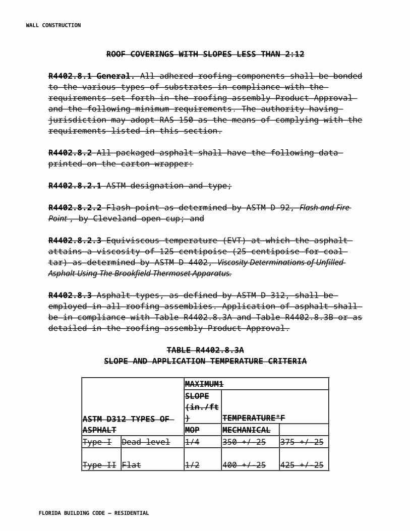
f. Torsional Analysis of Steel Members, AISC. g. Engineering for Steel Construction, AISC. h. Detailing for Steel Construction, AISC. i. Iron and Steel Beams - 1873 to 1952, AISC. j. Plastic Design of Braced Multistory Steel Frames, AISC. k. Torsional Analysis of Steel Members, AISC. 2. American Iron and Steel Institute, AISI: e. Cold-Formed Steel Design Manual, AISI f. Specifications for the Design of Light-gauge Cold-Formed Stainless Structural Members, AISI. g. Specification for the Criteria for Structural Application of Steel Cables for Buildings, AISI.
i. Design Manual for Structural Tubing, AISI. 3. American National Standards Institute/American Society of Civil Engineers, ANSI/ASCE. a. Specifications for the Design and Construction of Composite Slabs and Commentary on Specifications for the Design and Construction of Composite Slabs, ANSI/ASCE 3. b. Specifications for the Design of Cold-Formed Stainless Steel Structural Members, ANSI/ASCE 8.
4. American National Standards Institute/American Welding Society, ANSI/AWS a. Standard Welding Procedure and Performance Qualification, AWS B2.1. b. Recommended Practice for Stud Welding, AWS C5.4. c. Structural Welding Code - Steel, ANSI/AWS D1.1. d. Structural Welding Code - Sheet Metal, AWS D1.3. e. Structural Welding Code – Reinforcing Steel, ANSI/AWS D1.4 f. Specification for Welding of Sheet Metal, AWS D9.1. g. Standard for Qualification of Welding Procedures and Welders for Piping and Tubing, AWS D10.9.
5. American Society for Testing and materials, ASTM. a. Standard Specification for General Requirements for Rolled Steel Plates, Shapes, b. Sheet Piling and Bars for Structural Use, ASTM A 6. b. Standard Specifications for High-Strength Bolts for Structural Steel Joints, ASTM A 325. c. Standard Specification for Heat-Treated Steel Structural Bolts. 150 KSI Minimum Tensile Strength, ASTM A 490. d. Standard Specification for General Requirements for Steel Sheet, Zinc Coated (Galvanized) by the Hot Dip Process, ASTM A 525. 6. National Association of Architectural Metal Manufacturers, NAAMM. a. Metal Grating Manual, NAAMM. 7. Rack Manufacturers Institute/American National Standards Institute, RMI/ANSI. a. Industrial Steel Storage Racks Manual, RMI. b. Manual of Safety Practices - A code of Practices for the Use of Industrial and Commercial Steel Storage Racks, RMI/ANSI MH16.2.
WALL CONSTRUCTION
FLORIDA BUILDING CODE — RESIDENTIAL
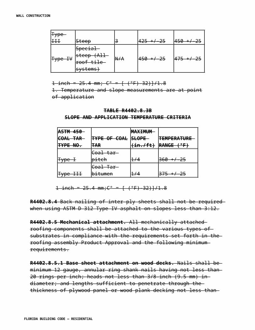
8. Research Council on Structural Connections of the Engineering Foundation, RCSCEF. a. Specification for Structural Joints Using ASTM A 325 or A 490 Bolts, RCSCEF. 10. Steel Deck Institute, Inc., SDI. a. Standard Practice Details, SDI. b. SDI Manual of Construction with Steel Deck, SDI. c. Deck Damage and Penetrations, SDI. d. Steel Deck Institute Design Manual. e. LRFD Design Manual for Composite Beams and Girders with Steel Deck, SDI. f. Diaphragm Design Manual, SDI.
11. Steel Joist Institute, SJI. a. Standard Specifications, Load Tables and Weight Tables for Steel Joists and Joist Girders, SJI. b. Structural Design of Steel Joist Roofs to Resist Ponding Loads, Technical Digest No. 3, SJI.g. Vibration of Steel Joist-Concrete Slab Floors, Technical Digest No. 5, SJI. h. Structural Design of Steel Joist Roofs to Resist Uplift Loads, Technical Digest No. 9, SJI. i. Welding of Open Web Steel, Technical Digest No. 8, SJI. j. Handling and Erection of Steel Joists and Joist Girders, Technical Digest No. 9, SJI. k. 60-Year Steel Joist Manual, SJI. b. A Guide to the Shop Painting of Structural Steel, SSPC/AISC. 13. Underwriters Laboratories, Inc., UL. a. Test for Uplift Resistance of Roof Assemblies, UL 580. 14. Welded Steel Tube Institute, Inc., WSTI. a. Manual of Cold Formed Welded Structural Steel Tube.
SECTION R4408.2HIGH-VELOCITY HURRICANE ZONES —
MATERIAL
R4408.2.1 Steel. Steel shall conform to the physical requirements set forth in the applicable standard in Section R4408.1.3.
R4408.2.2 High-strength steel bolts. High-strength steel bolts shall conform to the requirements set forth in the applicable standards of Section R4408.1.3.
R4408.2.3 Used and damaged material. All steel shall be straight and true, and any section damaged to be out of shape shall not be used. Steel previously used or fabricated for use or fabricated in error shall not be used except with the approval of the building official. Filled holes or welds shall not be concealed. Straightened or retempered fire-burned steel shall not be used except with the approval of the building official.
R4408.2.4 Tests. The building official may require tests and/or mill records to determine the
WALL CONSTRUCTION
FLORIDA BUILDING CODE — RESIDENTIAL
quality of materials.
R4408.2.5 Ribbed bolts. Ribbed bolts shall be made from carbon manganese steel with a minimum tensile strength of 70,000 psi (482.7 MPa).
SECTION R4408.3HIGH-VELOCITY HURRICANE ZONES —
DESIGN LOADS
R4408.3.1 Design shall be based on the dead, live, wind and other loads set forth in Section R4403 and the additional stress considerations set forth in this section.
SECTION R4408.4HIGH-VELOCITY HURRICANE ZONES —
MINIMUM THICKNESS OF MATERIAL
R4408.4.1 The minimum thickness of material shall not be less than as set forth in the applicable standards listed in Section R4408.1.3 except as otherwise set forth herein.
SECTION R4408.5HIGH-VELOCITY HURRICANE ZONES —
CONNECTIONS
R4408.5.1 Connections shall conform to the requirements of the applicable standards set forth in Section R4408.1.3.
R4408.5.2 A Florida-registered architect or licensed engineer shall inspect the welding and high-strength bolting of structural steel framing and welding, bolting and fastening of lightweight material systems and metal sidings of buildings with areas exceeding 1,000 square feet (93 m2).
R4408.5.3 Welding in the shop or field may be done only by AWS certified welders.
SECTION R4408.6HIGH-VELOCITY HURRICANE ZONES —
TUBULAR COLUMNS
R4408.6.1 Tubular columns and other primary compression members, excluding secondary
WALL CONSTRUCTION
FLORIDA BUILDING CODE — RESIDENTIAL
posts and struts not subject to bending and whose design load does not exceed 2,000 pounds (8900 N), shall have a minimum least dimension of 21/2 inches (64 mm) and a minimum wall thickness of 3/16 inch (4.8 mm).
R4408.6.2 Tubular members when filled with concrete shall have 1/4 inch (6.4 mm) diameter pressure relief holes drilled through the shell, within 6 inches (152 mm) of the top and bottom of the exposed length of the member and one hole at mid-height.
R4408.6.3 Concrete fill in tubular members shall not be assumed to carry any of the load except in compression members having a least dimension of 8 inches (203 mm) or greater and having a 1-inch (25 mm) inspection hole in the plate at each end.
SECTION R4408.8HIGH-VELOCITY HURRICANE ZONES —
OPEN WEB STEEL JOISTS
R4408.8.1 Standards. Open web steel joists shall comply with the standards set forth in Section R4408.1.3.
R4408.8.2 Statements of responsibilities of architects and professional engineers on the design of structural systems using open web steel joists.
R4408.8.2.1 The structural construction documents shall designate the standards for joist design and shall indicate layout, end supports, anchorage, bridging requirements, etc., including connections to walls. The structural construction documents shall indicate special requirements for concentrated loads, openings, extended ends and resistance to uplift.
R4408.8.2.2 The structural engineer of record and/or the architect of record shall require structural submittals for the structural engineer of record's review and/or the architect of record's review as an indication that his or her intent has been understood and that the specified criteria have been used. The structural submittals, unless catalog submittals, shall bear the impressed seal, signature and date of the specialty engineer who prepared them.
R4408.8.2.3 The structural submittals shall identify the specific project, shall list the design criteria and shall show all joist location information and details necessary for proper installation.
R4408.8.3 Design. R4408.8.3.1 Open web steel joist systems shall be designed to accommodate the loads and forces set forth in Section R4403.
R4408.8.3.2 Net uplift forces for all zones, applied to the joist systems, shall be clearly indicated on the structural construction documents.
R4408.8.3.3 Where the net uplift force is equal to or greater than the gravity load of construction, all web
WALL CONSTRUCTION
FLORIDA BUILDING CODE — RESIDENTIAL
and bottom chord members shall comply with slenderness ratio requirements for top chord and for compression members other than top chord as provided for in the standards set forth in Section R4408.1.3(11).
R4408.8.3.4 The slenderness ratio about the horizontal axis can be used in determining the capacity of the top chord provided the top chord is stayed laterally by the deck system. The top chord for superimposed dead and live loads shall be considered to be stayed laterally if: 1. A poured-in-place concrete slab is in direct contact with the top chord. 2. A light gauge steel deck complying with Section R4408.9 is fastened to the top chord. 3. Any other approved deck system such that attachments of the top chord to the deck are capable of resisting a lateral force specified in the standard set forth in Section R4408.1.3 and the spacing of the fasteners does not exceed 24 inches (610 mm) along the chord.
R4408.8.3.5 When the bottom chord under net uplift loads is in compression, the bottom chord shall be stayed laterally by a bracing system adequately anchored at each end.
R4408.8.3.6 Fastenings shall be bolting, welding or other approved fastening device that provides a resistance to lateral movement as required by rational analysis or by test, but not less than 400 pounds per foot (5838 N/m).
R4408.8.4 Connections. The joints and connections of members of steel joists shall be made by welding or bolting.
R4408.8.5 Bridging.
R4408.8.5.1 All bridging and anchors shall be completely installed before application of any construction loads. Bridging shall secure the chords against lateral movement and shall position and hold the joists vertical and in a straight line.
R4408.8.5.2 Bridging members shall be of material having a thickness not less than: 1. 1/8 inch (3.2 mm) for hot-rolled sections. 2. 16 gauge for cold-formed sections. 3. 1/2 inch (12.7 mm) diameter for round members.
R4408.8.5.3 Bridging shall be connected to the chords of the joists by welding, bolting or other positive mechanical means. Each attachment shall be capable of resisting a horizontal force specified in the standard set forth in Section R4408.1.3.
R4408.8.5.4 Bridging shall be connected to the chords of the joists by bolting or welding at all points of contact and shall be capable of transmitting the forces required of the bridging members. The ends of all bridging lines shall terminate at walls or beams and shall be anchored thereto and where anchorage is not possible, stability shall be provided by additional bracing.
R4408.8.5.5 Where uplift forces are a design requirement, a single line of continuous bottom chord bridging shall be provided near the first panel points.
WALL CONSTRUCTION
FLORIDA BUILDING CODE — RESIDENTIAL
R4408.8.6 End supports and anchorage.
R4408.8.6.1 Joists shall not bear directly on unit masonry unless masonry is designed as engineered unit masonry with properly reinforced, grout-filled continuous bond beam.
R4408.8.6.2 The ends of every joist shall be bolted, welded or encased in concrete at each point of bearing to provide not less resistance in any direction than 50 percent of the Steel Joist Institute rated end reaction horizontally and 100 percent of the net uplift reaction specified in the structural construction documents.
R4408.8.6.3 The ends of joists shall have a minimum bearing, on reinforced concrete and steel supports as specified in the standard set forth in Section R4408.1.3(11).
R4408.8.7 Fabrication. Steel joists shall be manufactured by plants having a certificate of competency issued by the authority having jurisdiction.
SECTION R4408.9HIGH VELOCITY HURRICANE ZONES —COLD-FORMED STEEL CONSTRUCTION
R4408.9.1 Cold-formed steel construction shall include individual structural members, structural decks or wall panels, and nonstructural roofing, siding and other construction elements formed from sheet or strip steel and as set forth in Section R4408.1.3(2).
R4408.9.2 Standards. Cold-formed steel used in structural applications shall conform to the standards set forth in Section R4408.1.3(2).
R4408.9.2.1 Galvanizing as referred to herein is to be zinc coating conforming to the standard set forth in Section R4408.1.3(5)(d).
R4408.9.3 Individual structural members. Design, fabrication and erection of individual cold-formed steel structural members shall be as set forth herein.
R4408.9.3.1 All structural members shall be positively connected to resist the loads set forth in Section R4403.
R4408.9.3.2 All connections shall be by welding, riveting, bolting or other approved fastening devices or methods providing positive attachment and resistance to loosening. Fasteners shall be of compatible material.
R4408.9.3.3 Cables and rods shall not be used as lateral bracing in habitable structures. Lateral bracing, when used, shall have a slenderness ratio of 300 or less, unless restricted by any other section of this code.
R4408.9.3.4 Doors and windows in pre-engineered metal building systems shall be designed as
WALL CONSTRUCTION
FLORIDA BUILDING CODE — RESIDENTIAL

a structural component member and shall conform to all requirements in this section.
R4408.9.3.5 All doors shall be anchored as part of the frame in the closed position.
R4408.9.3.6 No increase in strength shall be allowed for the effect of cold work.
R4408.9.4 Structural sheets. Decks and panels with or without an approved fill material may be designed as diaphragms in accordance with Diaphragm Design Manual of the Steel Deck Institute, provided other limitations in this code are complied with.
R4408.9.4.1 Poured fill on roof and floor decks shall not be assumed to have any structural value to support or resist vertical or lateral loads or to provide stability or diaphragm action unless so designed, and poured fill and/or applied materials do not degrade when subjected to moisture.
R4408.9.4.2 Positive attachment of sheets shall be provided to resist uplift forces. Attachment shall be as set forth in Section R4408.9.3.1 and as required by rational analysis, and/or tests, but not less frequently than the following maximum spacing: 1. One fastener shall be placed near the corner of each sheet or at overlapping corners of sheets. 2. Along each supporting member, the spacing of fasteners shall not exceed 8 inches (203 mm) on centers at ends of sheets or 12 inches (305 mm) on centers. 3. The spacing of edge fasteners between panels, and between panels and supporting members, parallel to the direction of span, where continuous interlock is not otherwise provided shall be not more than 12 inches (305 mm) on centers. 4. Fastening shall be by bolting, welding or other approved fastening device that provides a resistance to lateral movement as required by rational analysis or by test, but not less than 400 pounds per lineal foot (5838 N/m). 5. Poured lightweight concrete fill will be acceptable as continuous interlock. 6. Attachment to the supporting structure shall be provided at all perimeters and discontinuities by fasteners spaced at no more than 8 inches (203 mm) on center. 7. Wall panels shall be attached as set forth in Section R4408.9.4.2(1),(2) and (3).
R4408.9.4.3 Metal siding and roof panels shall be not less than 24 gauge.
Exception: Roof panels having an approved fill material designed to act as a diaphragm may use a lighter deck gauge provided that the Product Approval for the fill material allows its use over the same deck gauge, but in no case shall the deck be less than 26 gauge. The permit applicant shall provide the building official with signed and sealed structural calculations for the diaphragm design prepared by a licensed architect or engineer proficient in structural design. The diaphragm design shall comply with the applicable requirements of Section R4403 and Section R4408.
R4408.9.4.4 Deflection of metal siding and roof panels shall not exceed L/240.
R4408.9.4.5 The bending stress of metal siding and roof panels shall be designed using a safety
WALL CONSTRUCTION
FLORIDA BUILDING CODE — RESIDENTIAL
factor of not less than 2.5.
R4408.9.4.6 Minimum roof decking uplift loads shall comply with the design requirements of Section R4403 utilizing rational analysis, but not less than UL 580 Class 90.
R4408.9.4.7 Reserved.
R4408.9.4.8 Metal siding and roof panels shall be designed, where possible, to be continuous over two or more spans.
R4408.9.5 Nonstructural sheets. Steel sheet sections not suitable by rational analysis for self-supporting structural sheets shall be termed roofing and siding. Roofing and siding shall be used only over solid wood sheathing or equivalent backing.
R4408.9.5.1 Attachment of sheets shall be as set forth in Section R4408.9.4.2
R4408.9.6 Protection of metal. All members shall be treated with protective paint coatings or equivalent protection except as permitted in Sections R4408.9.6.1 or R4408.9.6.2.
R4408.9.6.1 All steel sheets having a thickness of less than 20 gauge, i.e., materials of higher gauge, shall be galvanized in accordance with the standards of Section R4408.1.3(5)(d) herein to provide a minimum coating designation of G90.
R4408.9.6.2 Abrasions or damages to the protective coating shall be spot-treated with a material and in a manner compatible to the shop protective coating.
R4408.9.7 Welding shall conform to the requirements of Sections R4408.1.3, R4408.5.2 and R4408.5.3.
SECTION R4408.10HIGH-VELOCITY HURRICANE ZONES —
PREENGINEERED, PREFABRICATED METAL BUILDING SYSTEMS AND COMPONENTS (PREENGINEERED STRUCTURES)
R4408.10.1 Scope. Metal buildings (pre-engineered structures) shall include, but not be limited to, tapered or straight web structural steel frames and predominantly cold formed steel secondary components, including, but not limited to, girts, purlins, roof sheets, wall sheets, etc.
R4408.10.2 Standards. Frames and components shall comply with the standards set forth in Section R4408.1.3.
R4408.10.3 Structural construction documents for pre-engineered structures shall indicate the necessary measures for adapting the structures to the specific site. The structural construction documents shall indicate all openings, concentrated loads and other special requirements.
WALL CONSTRUCTION
FLORIDA BUILDING CODE — RESIDENTIAL
Foundation conditions assumed in the design shall be indicated as well as the location and magnitude of building reactions on that foundation under all design conditions.
R4408.10.5 Design. A building or component system in this section shall have a structural engineer of record and/or architect of record responsible for the overall design and performance of the entire building including the foundation and the anchorage of the pre-engineered metal systems buildings thereto. The structural engineer of record and/or the architect of record shall provide the structural construction documents necessary for permitting.
R4408.10.5.1 Calculations for drift and deflection of the metal system building shall be by the specialty engineer.
R4408.10.5.2 Calculations for deflection shall be done using only the bare frame method. Reductions based on engineering judgment using the assumed composite stiffness of the building envelope shall not be allowed. Drift shall follow AISC serviceability design considerations for low-rise buildings. The use of composite stiffness for deflection calculations shall be permitted only when actual calculations for the stiffness are included with the design for the specific project. When maximum deflections are specified by the structural construction documents, calculations shall be included in the design data.
R4408.10.5.3 The manufacturer shall design the metal system building and/or component system in accordance with the provisions of Section R4403, and the design shall be signed, dated and sealed by the specialty engineer and reviewed by the structural engineer of record and/or the architect of record. The manufacturer of the metal system building and or component system shall be responsible to provide all reactions to the structural engineer of record and/or the architect of record.
R4408.10.5.4 Fastenings shall be by bolting, welding or other approved fastening device that provides a resistance to lateral movement as required by rational analysis or by test, but not less than 400 pounds per lineal foot (5838 N/m).
R4408.10.7 Fabrication and erection.
R4408.10.7.2 Temporary bracing shall be provided during erection and shall remain in place until all structural frames, purlins, girts, flange braces, cable or rod bracing and sheets used as diaphragms have been installed,
R4408.10.8 Roof sheets, wall sheets, roof panels and wall panels.
R4408.10.8.2 The fusion welding of structural members and structural sheets defined in Section R4408.9.4 and less than 22 gauge (0.0299 inch nominal) in thickness shall have minimum of 5/8 inch (17 mm) diameter welds through weld washers not less than 14-gauge in thickness and 1 inch (25 mm) in diameter, contoured if necessary to provide continuous contact, or an equivalent device.
R4408.10.8.3 Clip-mounted standing-seam roof sheets shall not be used as diaphragms nor shall they be considered as adequate lateral bracing of the flange of the secondary member to which they are attached unless one or both of these features are designed into the sheathing system and the manufacturer can
WALL CONSTRUCTION
FLORIDA BUILDING CODE — RESIDENTIAL
certify by testing and/or analysis that such capabilities exist and are appropriately defined.
R4408.10.8.4 Structural standing-seam roof sheets shall be a minimum of 24 gauge (0.0239 inch nominal) in thickness.
R4408.10.8.5 Direct screw attached roof and wall sheets may be used as diaphragms provided the sheets are a minimum of 24 gauge (0.0239 inch nominal) in thickness. Additionally, these sheets shall be considered to laterally brace the flange of the secondary member to which they are attached.
R4408.10.8.6 See Section R4408.9 for additional requirements for roof sheets, wall sheets, roof panels and wall panels.
R4408.10.9 Roof purlins and wall girts.
R4408.10.9.1 Adequate bracing shall be provided to the compression flanges of secondary members with special attention to those members subject to uplift or outward pressures where no roof or wall sheets are attached to provide such bracing. Sag rods shall not be considered bracing when located in the neutral axis of the web of the secondary members.
R4408.10.9.2 Roof purlins and wall girts shall be laterally braced in addition to relying on deck and panel diaphragm action.
R4408.10.9.3 The ends and bearing points of secondary members shall be designed to carry 100 percent of dead, live and collateral loads superimposed on them by wind.
R4408.10.9.4 Upward or outward forces of wind are to be calculated without live and collateral loads. When downward or inward forces caused by wind are involved, the dead forces plus collateral load forces must be combined but the roof live load may be omitted.
R4408.10.10 Individual structural members.
R4408.10.10.1 Cables and rods shall not be used as lateral bracing in habitable structures. Lateral bracing, when used, shall have a slenderness ratio of 300 or less, unless restricted by any other section of this code.
R4408.10.10.3 All doors shall be anchored as part of the frame in the closed position.
R4408.10.10.4 No increase in strength shall be allowed for the effect of cold work.
R4408.10.10.5 See Section R4408.9 for additional requirements for preengineered metal building systems and components.
SECTION R4408.11
WALL CONSTRUCTION
FLORIDA BUILDING CODE — RESIDENTIAL
HIGH-VELOCITY HURRICANE ZONES —CHAIN LINK FENCES
R4408.11.1 Chain link fences in excess of 12 feet (3.7 m) in height shall be designed according to the loads specified in Section R4403.
R4408.11.2 Chain link fences less than 12 feet (3.7 m) in height shall be designed according to the loads specified in Section R4403 or may be constructed to meet the minimum requirements specified in Table R4408.11.
[S5015 AS]
Section R4409. Change to read as follows:
SECTION R4409HIGH-VELOCITY HURRICANE ZONES—
WOOD
R4409.1 General Refer to Chapter 23 of the Florida Building Code, Building .
R4409.1.1 Design. Wood members and their fastenings shall be designed to comply with this code by methods based on rational analysis or approved laboratory testing procedures, both performed in accordance with fundamental principles of theoretical and applied mechanics.
R4409.1.2 Workmanship. Wood members shall be framed, anchored, tied and braced to develop the strength and rigidity necessary for the purposes for which they are used and to resist the loads imposed as set forth in this code. Wood construction shall be in conformance with the tolerances, quality and methods of construction as prescribed by the standards in Chapter 43 of this code.
R4409.1.3 Fabrication.
R4409.1.3.1 Preparation, fabrication and installation of wood members and the glues, connectors and mechanical devices for fastening shall conform to good engineering practice.
R4409.1.3.2 Any person desiring to manufacture or fabricate wood truss assemblies shall obtain a certificate of competency from the authority having jurisdiction.
R4409.1.4 The following standards, as set forth in Chapter 43 of this code, are hereby adopted for the design and quality of wood members and their fastenings:
WALL CONSTRUCTION
FLORIDA BUILDING CODE — RESIDENTIAL
R4409.1.4.1 American Hardboard Products Association887-B Wilmette Road, Palatine, IL 60067 AHA 1. Basic Hardboard ANSI/AHA A135.4-1982 2. Prefinished Hardboard Paneling ANSI/AHA A135.5-1982 3. Hardboard Siding ANSI/AHA A135.6-1990 4. Cellulosic Fiberboard ANSI/AHA A194.1-1985 5. Recommended Product and Application Specification - Structural Insulating Roof Deck, I.B. Spec. No. 1 6. Recommended Product and Application Specification - 1/2 inch Fiberboard Nail-Base- Sheathing I.B. Spec. No. 2 7. Recommended Product and Application Specification - 1/2 inch Intermediate Fiberboard Sheathing I.B. Spec. No. 3
R4409.1.4.2 American Institute of Timber Construction333 West Hampden Avenue, Englewood, CO80110 AITC 1. Typical Construction Details AITC 104 2. Code of Suggested Practices AITC 106 3. Standard for Heavy Timber Construction AITC 108 4. Standard for Preservative Treatment for Structural Glued Laminated Timber AITC 109 5. Standard Appearance Grades for Structural Glued Laminated Timber AITC 110 6. Standard for Tongue and Groove Heavy Timber Roof Decking AITC 112 7. Standard for Dimensions of Glued Laminated Structural Members AITC 113 8. Standard Specifications for Structural Glued Laminated Timber of Softwood Species AITC 117 9. Standard Specifications for Hardwood Glued Laminated Timber AITC 119 10. Technical Report No. 7, Calculation of Fire Resistance of Glued Laminated Timber 11. Structural Glued Laminated Timber ANSI/AITC A190.1
TABLE R4408.11CHAIN LINK FENCE MINIMUM REQUIREMENTS
Fence Height (ft) Terminal Post Line Post Terminal Post Concrete Line Post ConcreteDimensions Dimensions Foundation Size Foundation Size(in inches) (in inches) (diameter × depth) (diameter × depth) (o.d. × wall thickness) (o.d. × wall thickness) (in inches) (in inches)
Up to 4 23/8 × 0.042 15/8 × 0.047 10 × 24 8 × 24Over 4 to 5 23/8 × 0.042 17/8 × 0.055 10 × 24 8 × 24Over 5 to 6 23/8 × 0.042 17/8 × 0.065 10 × 24 8 × 24Over 6 to 8 23/8 × 0.110 23/8 × 0.095 10 × 36 10 × 36Over 8 to 10 27/8 × 0.110 23/8 × 0.130 12 × 40 10 × 40Over 10 to 12 27/8 × 0.160 27/8 × 0.120 12 × 42 12 × 42
WALL CONSTRUCTION
FLORIDA BUILDING CODE — RESIDENTIAL
For SI: 1 inch = 25.4 mm.Notes:1. This Table is applicable only to fences with unrestricted airflow.2. Fabric: 121/2 gauge minimum.3. Tension Bands: Use one less than the height of the fence in feet evenly spaced.4. Fabric Ties: Must be minimum the same gauge of the fabric.5. Fabric Tie Spacing on the Top Rail: Five ties between posts, evenly spaced.6. Fabric Tie Spacing on Line Posts: One less than height of the fence in feet, evenly spaced.7. Either top rail or top tension wire shall be used.8. Braces must be used at Terminal Posts if top tension wire is used instead of Top Rail.9. Post Spacing: 10 foot (3 m) on center maximum.10. Posts shall be embedded to within 6 inch (152 mm) from the bottom of the foundation.11. In order to follow the contour of the land, the bottom of the fence may clear the contour of the ground by up to 5 inch (127 mm) without increasing table values to the next higher limit.
R4409.1.4.3 APA The Engineered Wood Association (Formerly APA American Plywood Association) P.O. Box 11700, Tacoma, WA 98411 1. APA Design Construction Guide, Residential and Commercial E30D 2. Plywood Design Specification Y510J 3. Plywood Design Specification-Design and Fabrication of Plywood Beams Supplement No. 1 S811 4. Plywood Design Specification-Design and Fabrication of Plywood Beams Supplement No. 2 S812 5. Plywood Design Specification-Design and Fabrication of Plywood Stressed-Skin Panels Supplement No. 3 U813 6. Plywood Design Specifications-Design and Fabrication of Plywood Sandwich Panels Supplement No. 4 U814 7. Plywood Design Specifications-Design and Fabrication of All-Plywood Beams. Supplement No. 5 H815 8. Plywood Folded Plate, Laboratory Report 21 V910 9. APA Design/Construction Guide Diaphragms L350 10. Performance Standards and Policies for Structural-Use Panels PRP-108 11. 303 Siding Manufacturing Specifications B840
R4409.1.4.4 American Society for Testing Materials1916 Race Street, Philadelphia, PA 19103-1187 ASTM 1. Standard Test Methods for Mechanical Fasteners in Wood D 1761 2. Accelerated Weathering on Fire-Retardant Treated Wood for Fire Testing D 2898 3. Surface Burning Characteristics of Building Materials E 84 4. Hygroscopic Properties of Fire-Retardant Wood and Wood-Base Products D 3201 5. Standard Specifications for Adhesives for Field-Gluing Plywood to Lumber Framing for Floor Systems D 3498
R4409.1.4.5 American Wood Preservers Association
WALL CONSTRUCTION
FLORIDA BUILDING CODE — RESIDENTIAL
P.O. Box 361784, Birmingham, AL 35236-1784
1. AWPA Use Category Systems Standard U1 2. AWPA Standard M4 Care of Pressure Treated Wood Products
R4409.1.4.6 National Institute for Standards and Technology Standard Development Services Section, Standards Application and Analysis Division, Washington, D.C. 20234 NIST
1. Mat-Formed Particleboard CS236 2. Structural Glued Laminated Timber PS56 3. Construction and Industrial Plywood PS1 4. American Softwood Lumber Standard PS20 5. Performance Standard for Wood Based Structural Use Panels PS2*
*All wood-based structural panels except plywood shall have Product Approval and shall be tested in accordance with High-Velocity Hurricane Zone testing protocols.
R4409.1.4.7 American Forest and Paper Association 1111 19 Street NW, Washington, D.C. 200361. ANSI/AF&PA National Design Specification for Wood Construction, 2001 20052. ANSI/AF&PA Design Values for Wood Construction, 2001 20053. Wood Structural Design Data, 19924. Span Tables for Joists and Rafters, 20055. Design Values for Joists and Rafters, 20056. Wood Construction Data No. 1, Details for Conventional Wood Frame Construction, 20017. Wood Construction Data No. 4, Plank-and-Beam Framing for Residential Building, 20038. Wood Construction Data No. 5, Heavy Timber Construction Details, 20049. Wood Construction Data No. 6, Design of Wood Frame Structures for Permanence, 200610. ANSI/AF&PA PWF-2007 Permanent Wood Foundation (PWF) Design Specification, 200711. ANSI/AF&PA WFCM-2001, Wood Frame Construction Manual for one and Two-Family Dwellings, 2001
R4409.1.4.8 Timber Company, Inc.2402 Daniels Street, Madison, WI 53704 TECO
Performance Standards and Policies for Structural use Panels. PRP-133
R4409.1.4.9 Truss Plate Institute218 N. Lee Street, Suite 312, Alexandria, VA 22314
1. National Design Standard for Metal Plate Connected Wood Truss Construction (Excluding Chapter 2). 2. Building Component Safety Information (BCSI 1-03) Guide to Good Practice for Handling, Installing & Bracing of Metal Plate Connected Wood Trusses [A joint publication with the Wood Truss Council of America (WTCA)].
WALL CONSTRUCTION
FLORIDA BUILDING CODE — RESIDENTIAL
SECTION R4409.2HIGH-VELOCITY HURRICANE ZONES—
QUALITY
R4409.2.1 Identification. All lumber used structurally, including end-jointed lumber, shall be identified by the grade mark of a lumber grading or inspection bureau or agency approved by the Board of Review of the American Lumber Standards Committee or the Canadian Lumber Standards Administrative Board: except that precut material, rough-sawn lumber and lumber thicker than 2 inches (51 mm) may be covered by a certificate of inspection in lieu of grade marking. The glued joints in end-jointed lumber, when used for load supporting purposes, shall be certified to be in accordance with the appropriate grading rules.
R4409.2.1.1 Structural glued laminated timber shall be manufactured and identified as required in ANSI/AITC 190.1 as adopted in Section R4409.1.4.
R4409.2.1.2 All wood-based structural panels used structurally, including siding, roof sheathing, wall sheathing, floor sheathing, diaphragms and built-up members, shall be identified for grade and exposure level by the grade stamp of an approved testing and grading agency indicating conformance with PS-1, PS-2, APA PRP-108 or TECO PRP-133 as adopted in Section R4409.1.4.
R4409.2.1.3 Wood shingles and/or shakes shall be identified by the grade mark of an approved grading or inspection bureau or agency.
R4409.2.1.4 Fiberboard for its various uses shall conform to ANSI/AHA A 194.1.
R4409.2.1.5 Hardboard shall conform to AHA standards as adopted in Section R4409.1.4, and shall be identified as to classification.
R4409.2.1.6 Particleboard shall conform to the mat-formed particleboard standard, NIST CS236, as adopted in Section R4409.1.4.6, and shall be identified by the grade mark or certificate of inspection issued by an approved agency.
R4409.2.1.8 All lumber, sawn timber, wood-based structural panels and poles supporting permanent structures and required by this code to be pressure treated and as described in the AWPA standards shall bear the quality mark of an approved inspection agency which maintains continued supervision, testing and inspection over the product. Agencies shall be accredited in accordance with the procedures of the American Lumber Standard (PS 20) or approved equivalent.
R4409.2.1.9 Pressure-treated poles shall be treated in accordance with AWPA U1 for sawn timber posts (Commodity Specification A, Use Category 4B) and for round timber posts
WALL CONSTRUCTION
FLORIDA BUILDING CODE — RESIDENTIAL
(Commodity Specification B, Use Category 4B).
R4409.2.1.10 The quality mark shall contain, as a minimum, the following information: 1. The treating company and plant location 2. The AWPA standard to which the product is treated 3. The trademark of an approved inspection agency which maintains continued supervision, testing and inspection over the quality of the product as described in the AWPA standards 4. The preservative used 5. The amount of retention of the chemical per cubic foot of wood 6. If applicable, the method of drying after treatment 7. The purpose for which the wood has been treated: ground contact, above ground or foundation
Exception: When the size of individual pieces, e.g. lumber less than 1 inch (25 mm) in nominal thickness, or lumber less than nominal 1x5 or 2x4, or lumber 36 inches (914 mm) and shorter, except that 5/4x4 shall be quality marked, prevents application of full legible marks, the quality mark shall be applied by stamping the faces of exterior pieces or by end labeling not less than 25 percent of the pieces of a bundled unit.
R4409.2.1.11 All wood-based structural panels, including those made of fiberboard, hardboard and particleboard shall have Product Approval. Product Approval shall be given upon certification by an approved independent testing laboratory that the product: 1. Complies with the applicable standards set forth above 2. The product complies with the manufacturer's published design properties before and after a wet-dry cycle 3. The product when tested dry maintains a safety factor of 2:1 and when tested after the cycles specified in Section R4409.2.1.11(2) above maintains a safety factor of 1.5:1. Testing shall be as specified in the testing protocol.
R4409.2.2 Wood-based structural panels permanently exposed in outdoor locations shall be rated for exterior use. When used for roof sheathing exposed to the outdoors on the underside or used structurally for wall, floor or roof cladding or for diaphragms, the panels shall be rated for Exposure 1 or exterior use.
R4409.2.3 All lumber 2 inches (51 mm) or less in thickness shall contain not more than 19 percent moisture at the time of permanent incorporation in a building or structure and/or at the time of treatment with a wood preservative.
R4409.2.4 Grade and species.
R4409.2.4.1 All structural wood members not limited by other sections of this section shall be of sufficient size and capacity to carry all loads as required by Section R4403 without exceeding the allowable design stresses specified in the National Design Specification for Wood Construction and in compliance with Section R4409.4.
WALL CONSTRUCTION
FLORIDA BUILDING CODE — RESIDENTIAL
R4409.2.4.2 Lumber boards used for floor and roof sheathing shall be in accordance with Table R4409.2.4.2.
TABLE R4409.2.4.2 MINIMUM GRADE REQUIREMENTS: BOARD GRADES
FLOOR OR ROOF SHEATHING GRADING RULESUtility NLGA, WCLIB or WWPANo. 4 Common or Utility NLGA, WCLIB, WWPA, NHPMA or NELMANo. 3 SPIBMerchantable RIS
SECTION R4409.3Reserved
SECTION R4409.4HIGH-VELOCITY HURRICANE ZONES—
UNIT STRESSES
R4409.4.1 General.
R4409.4.1.1 Lumber used for joists, rafters, trusses, columns, beams and/or other structural members shall be of no less strength than No. 2 grade of Southern Pine, Douglas Fir-Larch, Hem-Fir or Spruce-Pine-Fir. Joists and rafters shall be sized according to AF&PA Span Tables for Joists and Rafters adopted in Section R4409.1.4.
R4409.4.1.2 Lumber used for studs in exterior walls and interior bearing walls shall be of no less strength than Stud Grade of Southern Pine, Douglas Fir-Larch, Hem-Fir or Spruce-Pine-Fir and capable of resisting all loads determined in accordance with Section R4403. The unbraced height of the wall shall be no more than 8 feet 6 inches (2.6 m) (including top and bottom plates). Heights may be increased where justified by rational analysis prepared by a registered professional engineer or registered architect proficient in structural design.
R4409.4.1.4 The designer shall specify on the design drawings the size, spacing, species and grade of all load supporting members.
R4409.4.2 Allowable stress design value may be modified for repetitive, duration, etc., factors where design is by a registered professional engineer or registered architect proficient in structural design or where such modified values are reflected in the tables of the standards in Section R4409.1.4.
SECTION R4409.5HIGH-VELOCITY HURRICANE ZONES—
WALL CONSTRUCTION
FLORIDA BUILDING CODE — RESIDENTIAL
VERTICAL FRAMING
R4409.5.1 Studs in bearing and exterior walls. Studs in walls framing over 8 feet 6 inches (2.6 m) (including top and bottom plates) or supporting floor and roof loads shall be designed by rational analysis prepared by a registered professional engineer or registered architect proficient in structural design.
R4409.5.1.1 Minimum size. Studs shall be not less than 2x6 for exterior walls or 2x4 for interior bearing or load resisting walls unless designed by rational analysis by a registered licensed engineer or registered architect proficient in structural design.
R4409.5.1.2 Spacing. Studs shall be spaced not more than 16 inches (406 mm) on center unless designed by rational analysis as a system of columns and beams by a registered licensed engineer or registered architect proficient in structural design.
R4409.5.1.3 Placing.
R4409.5.1.3.1 Studs in exterior and bearing walls shall be placed with the longer dimension perpendicular to the wall.
R4409.5.1.3.2 Studs in exterior walls and in bearing walls shall be supported by foundation plates, sills, or girders or floor framing directly over supporting walls or girders. Stud bearing walls when perpendicular to supporting joists may be offset from supporting walls or girders not more than the depth of the joists unless such joists are designed for the extra loading conditions.
R4409.5.1.3.3 Stud walls framing into base plates of exterior walls and interior bearing walls resting on masonry or concrete shall be anchored past the plate to the masonry or concrete, or shall be anchored to a sill plate which is anchored in accordance with Section R4409.5.1.4.1 when the net wind uplift is up to 300 pounds per foot (4378 N/m).
R4409.5.1.4 Sills and/or base plates.
R4409.5.1.4.1 Sills and/or base plates, where provided in contact with masonry or concrete, shall be of an approved durable species or be treated with an approved preservative and shall be attached to the masonry or concrete with 1/2 inch (13 mm) diameter bolts with oversized washer spaced not over 2 feet (610 mm) apart and embedded not less than 7 inches (178 mm) into a grout filled cell of masonry or into concrete. Base plates shall be placed in a recess 3/4 inch (19 mm) deep and the width of the base plate at the edge of a concrete slab, beam/slab or any other type of construction which uses a masonry surface or concrete slab, or be provided with an alternate waterstop method as approved by the building official. Alternate methods of anchorage may be designed by rational analysis by a registered professional engineer or a registered architect proficient in structural design.
R4409.5.1.4.2 Where the base plate of a bearing wall is supported on joists or trusses running perpendicular to the wall and the studs from the wall above do not fall directly over a joist or truss, a double base plate or a single base plate supported by a minimum 2x4 inset ribbon shall
WALL CONSTRUCTION
FLORIDA BUILDING CODE — RESIDENTIAL
be used to support the upper stud wall.
R4409.5.1.5 Top plates.
R4409.5.1.5.1 The top plate of stud bearing walls shall be doubled and lapped at each intersection of walls and partitions.
R4409.5.1.5.2 Joints shall be lapped not less than 4 feet (1219 mm).
R4409.5.1.6 Corners. Corners of stud walls and partitions shall be framed solid by not less than three studs.
R4409.5.1.7 Splicing. Studs, other than end-jointed lumber, shall be spliced only at points where lateral support is provided.
R4409.5.1.8 Framing types.
R4409.5.1.8.1 Wood framing may be any one, or a combination of, the following types: Platform, balloon, plank and beam or pole type.
R4409.5.1.8.2 Exterior stud walls of two-story buildings shall be balloon-framed with studs continuous from foundation to second floor ceiling and with second floor joists supported as indicated in Section R4409.6.3.3. Gable end walls in wood frame buildings shall be balloon framed with studs continuous from foundation to roof.
Exception: Platform framing is allowed in buildings over one story in height provided an additional mandatory inspection for floor level connectors is made before the framing/firestopping inspection. Gable end walls shall be balloon framed with studs continuous from top floor to roof.
R4409.5.1.9 Notching.
R4409.5.1.9.1 Studs that carry loads in excess of 75 percent of their capacity shall not be notched or cut.
R4409.5.1.9.2 Studs that carry loads 75 percent or less of their capacity may be notched to one-third of the depth without limit of the number of consecutive studs.
R4409.5.1.10 Pipes in walls.
R4409.5.1.10.1 Stud walls and partitions containing pipes shall be framed to give proper clearance for the piping.
R4409.5.1.10.2 Where walls and partitions containing piping are parallel to floor joists, the joists shall be doubled and may be spaced to allow vertical passage of pipes.
WALL CONSTRUCTION
FLORIDA BUILDING CODE — RESIDENTIAL
R4409.5.1.10.3 Where vertical pipe positions necessitate the cutting of plates, a metal tie not less than 1inch by 1/8 inch (25 mm by 3 mm) shall be placed on each side of the plate across the opening and nailed with not less than two 16d or three 8d nails at each end.
R4409.5.1.11 Headers.
R4409.5.11.1 All headers in bearing walls shall be designed by rational analysis.
R4409.5.1.11.2 Headers or lintels over stud wall openings shall have not less than nominal 2-inch (51 mm) bearings.
R4409.5.1.12 Studs joining masonry or reinforced concrete walls. Where stud walls or partitions join masonry or concrete walls, such studs shall be secured against lateral movement by bolting to the masonry or concrete with 1/2 inch (13 mm) diameter anchor bolts with oversized washer spaced not more than 4 feet (1219 mm) apart and embedded not less than 5 inches (127 mm) into a grout filled cell or into concrete or as designed by a registered licensed engineer or registered architect proficient in structural design using rational analysis.
R4409.5.1.13 Wind bracing. Exterior stud walls shall be effectively wind-braced in accordance with Section R4409.9.3. Such bracing shall be designed by a registered licensed engineer or registered architect proficient in structural design.
R4409.5.1.14 The intermixing of wall framing described in this section with other types of structural wall systems as provided in this code shall not be permitted unless such wall framing and connections are designed by a registered professional engineer or registered architect proficient in structural design.
R4409.5.3 Columns and posts.
R4409.5.3.1 Columns and posts shall be framed to true end bearing, shall be securely anchored against lateral and vertical forces, and shall be designed by a registered professional engineer or registered architect proficient in structural design.
R4409.5.3.2 The bottom of columns and posts shall be protected against deterioration by an approved product or method.
R4409.5.3.3 Columns and posts shall be spliced only in regions where lateral support is adequately provided about both axes and is designed by rational analysis. Such design shall be prepared, signed and sealed by a registered professional engineer or registered architect proficient in structural design.
R4409.5.3.4 Design dimensions of columns and posts shall not be reduced by notching, cutting or boring.
SECTION R4409.6HIGH-VELOCITY HURRICANE ZONES — HORIZONTAL FRAMING
WALL CONSTRUCTION
FLORIDA BUILDING CODE — RESIDENTIAL
R4409.6.1 Size.
R4409.6.1.1 The minimum size of joists and rafters shall be as set forth in Section R4409.4.
R4409.6.1.2 The design of horizontal framing other than joists and rafters shall be as set forth in Section R4409.4.1.1.
R4409.6.3 Bearing.
R4409.6.3.1 Joists and rafters shall have not less than three inches of bearing, on wood, metal, grout filled masonry or concrete except as provided in Sections R4409.6.3.2, R4409.6.3.3 and R4409.6.3.4.
R4409.6.3.2 Masonry and concrete.
R4409.6.3.2.1 Joists and rafters may bear on and be anchored by steel strap anchor embedded into a grout filled cell of the masonry or reinforced concrete, as described in Section R4409.8.5.1, to a wood plate provided such wood plate is of an approved durable species or pressure treated with an approved preservative and such plate shall be not less than 2x4 and attached as per Section R4409.5.1.4.1. The net uplift on the plate shall be limited to 300 pounds per foot (4378 N/m).
R4409.6.3.2.2 Joists and rafters may bear on a product control approved channel-shaped metal saddle and fastened to the masonry by a steel strap anchor embedded into a grout filled cell of the masonry or concrete.
R4409.6.3.2.3 Joists and rafters may bear on masonry, provided that each joist or rafter in contact with masonry is of an approved durable species or pressure treated with an approved preservative and anchored as in Section R4409.6.3.2.2 above.
R4409.6.3.3 Floor joists may butt into a header beam if effectively toenailed and if an approved metal hanger providing not less than 3 inches (76 mm) of bearing transmits the vertical load to the top of the header, provided, however, that approved devices or other approved means of support may be used in lieu of such bearing. All hangers and devices shall have Product Approval.
R4409.6.3.4 Ceiling joists may butt into a header beam, as set forth for floor joists, or approved devices or other approved means of support may be used in lieu of such bearing. All devices shall have Product Approval.
R4409.6.3.5 In lieu of the above, bearing and anchorage may be designed by rational analysis by a registered professional engineer or registered architect proficient in structural design.
R4409.6.4 Splicing. Horizontal members shall not be spliced between supports except that properly designed splices or approved end-jointed lumber may be used.
WALL CONSTRUCTION
FLORIDA BUILDING CODE — RESIDENTIAL
R4409.6.5 Notching and boring.
R4409.6.5.1 Unless local unit stresses are calculated on the basis of reduced size, wood members in bending shall not be cut, notched or bored except as provided in Sections R4409.6.5.1.1 and R4409.6.5.1.2.
R4409.6.5.1.1 Notches may be cut in the top or bottom not deeper than one-sixth of the depth not longer than one-third of the depth of the member and shall not be located in the middle one-third of the span. Where members are notched at the ends, over bearing points, the notch depth shall not exceed one-fourth the member depth.
R4409.6.5.1.2 Holes may be bored in the middle one-third of the depth and length and not larger than one-sixth of the depth. Space between any two holes in the same joist shall be not less than the depth of the joist.
R4409.6.5.2 Where necessary to run service pipes in the space between the ceiling and floor larger than can be accommodated by the above provision, such ceilings shall be furred or provision made for headers or beams and/or for changing direction of the joists where the design permits.
R4409.6.6 Openings.
R4409.6.6.1 Joists shall be doubled adjacent to openings where more than one joist is cut out or shall be so increased in size or number as may be needed to meet the stress requirements.
R4409.6.6.2 Headers shall be of the same size as the joists and where supporting more than one joist shall be double members.
R4409.6.6.3 Headers shall be supported by approved metal hangers or ledgers or other approved members.
R4409.6.7 Wood entering masonry or reinforced concrete.
R4409.6.7.1 Wood joists, beams or girders which frame into masonry or reinforced concrete shall have a minimum of 1/2 inch (13 mm) air space at the top, end and sides or shall be preservative pressure treated or of an approved durable species.
R4409.6.7.2 Where masonry extends above such wood members, joists shall be fire-cut so the top edge does not enter the masonry more than 1 inch (25 mm) or shall be provided with wall plate boxes of self-releasing type or approved hangers.
R4409.6.9 Ceiling joists.
R4409.6.9.1 In buildings with pitched roofs the ceiling joists, where practicable, shall be nailed to the rafters and shall be designed to carry all imposed loads including but not limited to lateral
WALL CONSTRUCTION
FLORIDA BUILDING CODE — RESIDENTIAL
thrust.
R4409.6.9.2 Ceiling joists spanning more than 10 feet (3 m) shall be laterally supported at mid-span.
R4409.6.9.3 Ceiling joists shall not be used to support rafter loads unless the joists and connections are properly designed for the total load being imposed.
R4409.6.10 Roof framing. The permit documents shall include roof framing plans showing spacing and spans of all roof members indicating any fabricated elements to be designed and furnished by others and shall include the details for support and bearing of the roof structural system, for the permanent cross/lateral/diagonal bracing and anchorage required to resist dead, live and wind loads as set forth in Section R4403.9. The framing plans shall also indicate the uplift forces applied on the roof, sheathing type, thickness and nailing requirements for the sheathing. The roof framing plans shall be prepared by and bear the sign and seal of, a registered professional engineer or registered architect of record proficient in structural design.
R4409.6.11 Roof joists. Roof joists may cantilever over exterior walls as limited by the allowable stress, but the length of such cantilever shall not exceed half the length of the portion of the joist inside the building; and where the cantilever of tail joists exceeds 3 feet (914 mm), the roof joist acting as a header shall be doubled.
R4409.6.12 Roof rafters.
R4409.6.12.1 Hip rafters, valley rafters and ridge boards shall be provided and shall be not less in size than the largest rafter framing thereto nor less than required to support the loads.
R4409.6.12.2 Collar ties.
R4409.6.12.2.1 Collar ties and their connections shall be provided to resist the thrust of rafters and shall be designed by a registered engineer or registered architect proficient in structural design.
R4409.6.12.2.2 Collar ties shall not be required if the ridge is designed as a supporting beam. Such design shall be done by a registered licensed engineer or registered architect proficient in structural design.
R4409.6.12.2.3 Ceiling joists may serve as collar ties when properly designed by a registered professional engineer or registered architect proficient in structural design.
R4409.6.12.3 The actual roof and ceiling dead loads may be used to resist uplift loads, but the maximum combined dead load used to resist uplift loads shall not exceed 10) pounds per square foot (479 Pa).
R4409.6.13 Heavy timber construction. Heavy timber construction of floors or roofs shall comply with the standards in Section R4409.1.4. All heavy timber construction shall be
WALL CONSTRUCTION
FLORIDA BUILDING CODE — RESIDENTIAL
designed by a registered professional engineer or registered architect proficient in structural design to withstand the loads required in Section R4403.
R4409.6.14 Vertically laminated beams. Vertically laminated built-up beams shall be designed and made up of members continuous from bearing to bearing.
R4409.6.15 Glued laminated members. Glued laminated members shall be designed to comply with applicable AITC standards adopted by this code.
R4409.6.16 Stair stringers.
R4409.6.16.1 Stair stringers shall, where practicable, be framed to provide 4 inches (102 mm) of bearing at the ends.
R4409.6.17 Wood trusses.
R4409.6.17.1 Trussed rafters. Trussed rafters shall be designed by methods admitting of rational analysis by a registered professional engineer or registered architect proficient in structural design based on the standards set forth in Section R4409.1.4.
R4409.6.17.1.1 Where steel is used for connecting wood members, such connectors shall be not less than 20 U.S. gauge and shall be protected with a zinc coating conforming to the ASTM A361 Standard set forth in Chapter 43 of this code. Connectors shall have Product Approval or shall be designed by methods admitting of rational analysis by a registered professional engineer or registered architect proficient in structural design.
R4409.6.17.1.2 Where a ceiling is to be attached directly to the underside of trusses, the trusses shall be laterally braced with continuous 1x4 members nailed with 8d common nails to the upper side of the bottom chord at panel points but not to exceed 10 feet (3 m) apart. This lateral bracing shall be restrained at each end and at 20 foot (6 m) intervals. Drywall may be considered a rigid ceiling in enclosed areas where it is protected from the elements. The drywall ceiling is not to be considered a ceiling diaphragm.
R4409.6.17.1.3 Where a ceiling is to be attached to wood stripping which is nailed to the underside of the bottom chord of trusses with two 8d common nails at each intersection, stripping shall be not less than 1x3 spaced not more than 24 inches (610 mm) apart. Wood stripping may be replaced by furring channels. Furring channels shall be a minimum of 7/8 inch (22 mm) hat shaped channels weighing 287 pounds per 1000 lineal foot (41.4 kg per 100 m) with minimum based steel of 0.0179 inch (0.445 mm) and complying with ASTM C 645 attached to trusses with minimum two #6 11/4 inch (32 mm) screws per intersection. Said stripping or metal furring channels may serve also as the lateral bracing of the truss bottom chord so as to minimize the effects of buckling of the bottom chord when subjected to compressive stresses under reverse load conditions. In addition, the rigid ceiling that is created by this 1x3 stripping or metal furring channels must also be restrained from lateral movements, in accordance with the details provided by the architect or licensed engineer of record.
WALL CONSTRUCTION
FLORIDA BUILDING CODE — RESIDENTIAL
Exception: Where fire-rated design assembly does not allow for this specific installation, see Section R4409.6.17.1.2
R4409.6.17.1.4 Where a ceiling is attached to wood members suspended beneath trusses, the provisions of Section R4409.6.1 shall apply.
R4409.6.17.2 Prefabricated wood trusses. Prefabricated wood trusses shall comply with this section.
R4409.6.17.2.1 Design.
R4409.6.17.2.1.1 Prefabricated wood trusses shall be designed by a registered professional engineer (delegated engineer) and fabricated in accordance with the National Design Standard for Metal Plate Connected Wood Truss Construction of the Truss Plate Institute (TPI). The truss system designer (delegated engineer) shall prepare the truss system shop drawings. Such shop drawings shall be submitted to the building official for review and approval. The shop drawings shall meet the following requirements: 1. All shop drawings shall be in conformity with the architect or engineer of record framing plans unless prior written approval is obtained from the architect or engineer of record. If reframing is approved, the architect or engineer of record shall resubmit revised framing plans to the building official after receiving updated plans from the delegated engineer showing all adjustments necessary to safely transmit all applied loads to the foundation. 2. Permanent bracing of individual truss members may be required on certain members of the trusses to prevent the members from buckling in the plane normal to the trusses (buckling in the narrow direction). This bracing shall be designed for both upward and downward loads and shall be shown on the individual truss drawings [truss engineering usually shown on 81/2-inches by 11-inch (216 mm by 279 mm) sheets ("A" size drawings)]. The design of this bracing shall be the responsibility of the delegated engineer. The contractor shall be responsible for seeing that this bracing is properly installed. This bracing may be in the form of (but not limited) to "T" bracing of an individual member, or lateral bracing of a series of members common to a number of trusses. Where lateral bracing is used, this bracing shall be restrained against lateral movement, in accordance with details provided by the delegated engineer or by the architect or professional engineer of record. All details and sections required to show the size and connections of all secondary members will be supplied on the delegated engineering plans and shall show all framing, connections and bracing on one or more primary plans of minimum size 24 inches by 36 inches (610mm by 914 mm). 3. A size 81/2-inches by 11-inches (216 mm by 279 mm) cut sheets showing individual member design shall also be furnished to the architect or engineer of record so that all gravity and uplift loads shown on these cut sheets can be transferred to the primary plans. 4. The size and location of all plates at each joint shall be shown on the truss design drawings. 5. The connection between trusses shall be detailed in the shop drawings. Hip sets shall be detailed in a manner to indicate all connections according to engineering drawings for the attachment of skewed members. 6. Truss design drawings shall indicate the support and minimum bearing of the roof structural system, the permanent cross/lateral bracing, bracing to transfer member buckling
WALL CONSTRUCTION
FLORIDA BUILDING CODE — RESIDENTIAL
forces to the structure and all bracing and anchorage required to resist uplift and lateral forces. 7. Flat and floor trusses must be clearly marked so that they will be installed right side up. These marks must remain after the flooring, sheathing and insulation have been installed.
The intent of the above requirements is to provide all information on framing, connections and bracing on one composite set of plans approved by the architect or engineer of record to aid in the review, approval and field inspections for the portion of the property.
R4409.6.17.2.1.2 Trusses shall be designed for wind loads per Section R4403, uniformly distributed live, dead and concentrated loads, and such loads shall be indicated on the roof framing plans and the truss design drawings. Where a girder or truss is subjected to concentrated loads or any unusual loading condition, such conditions must be clearly indicated on the roof framing plans and on the truss design drawings. Where truss members have been cut, shifted or altered in any manner to meet construction needs or for any other reason, additional drawings and additional calculations must be prepared, signed and sealed by the truss designer (a Florida-delegated engineer). Such additional drawings and calculations must be approved by the engineer or architect of record and must be submitted to the building official for review and approval.
R4409.6.17.2.1.3 Roof trusses shall be designed for a minimum live load of 30 psf (1436 Pa), a minimum dead load of 15 psf (718 Pa) on the top chord, and a minimum dead load of 10 psf (479 Pa) on the bottom chord; and wind loads per Section R4409 of this code. Where the roof design is such that water is not directed to the interior of the roof and there are no parapets or other roof edge drainage obstructions, roof trusses with slopes of 11/2:12 or greater may be designed for a live load of 20 psf (958 Pa) and a minimum total load of 45 psf (2155 Pa). Adjustment of the allowable design stress for load duration shall be in accordance with National Design Specification for Wood Construction except that load duration factor for wind loads shall not exceed 1.33.
R4409.6.17.2.1.4 The allowable deflection under live load for trusses shall not exceed span/360 for plastered ceilings, span/240 for unplastered finished ceilings, or span/180 for trusses without a ceiling.
R4409.6.17.2.1.5 Flat roof trusses shall be designed for not less than the loads set forth in Section R4409.6.17.2.1.3 above, except that the dead load on the top chord may be taken as 10 psf (479 Pa) in lieu of 15 psf (718 Pa), and the total load reduced to 50 psf (2394 Pa). Adjustment of the allowable design stress for load duration shall be in accordance with National Design Specification for Wood Construction except that load duration factor for wind loads shall not exceed 1.33.
R4409.6.17.2.1.6 Where gable end trusses are permitted in this code, they shall be designed for a minimum live load of 30 psf (1436 Pa) and a minimum dead load of 15 psf (718 Pa) on the top chord. The minimum load of 10 psf (479 Pa) on the bottom chord may be omitted where continuous support is provided. In addition, the gable end trusses shall be designed to sustain wind load as specified in Section R4403 but not less than 30 psf (1436 Pa) perpendicular to the plane of the truss. Such trusses shall use a rationally designed system to resist lateral wind loads
WALL CONSTRUCTION
FLORIDA BUILDING CODE — RESIDENTIAL

and be anchored to the substructure at intervals no greater than 4 feet (1219 mm) on center to resist the uplift forces and shall be designed to transfer the loads to the substructure. The design of the system used to resist the lateral loads imposed on the truss shall be prepared by the engineer or architect of record.
R4409.6.17.2.1.7 When girders exceed two members and when girder reactions exceed the capacity of standard connectors or hangers, these reactions shall be shown on the drawings and the connection must be designed, signed and sealed by a registered professional engineer or registered architect proficient in structural design and such design shall be included as part of the shop drawings.
R4409.6.17.2.1.8 All trusses shall be properly braced to act as a system. Such bracing shall be included as part of the design document.
R4409.6.17.2.2 Materials and specifications.
R4409.6.17.2.2.1 Trusses shall be fabricated applying the design values listed in the standard Design Values for Wood Construction of the American Forest and Paper Association.
R4409.6.17.2.2.2 Top and bottom chords shall be of No. 2 grade or better. Web members shall be of No. 3 grade or better. A chord member is defined as the entire top or bottom truss member which may consist of shorter spliced pieces.
R4409.6.17.2.2.3 For trusses spanning 20 feet (6 m) or less, the minimum percentage of grade-marked members among top and bottom chords shall be 50 percent.
R4409.6.17.2.2.4 For trusses spanning more than 20 feet (6 m) the minimum percentage of grade-marked percent, and there shall be a minimum of one marked members among top and bottom chords shall be 75 web on each truss.
R4409.6.17.2.2.5 All lumber shall be 2x4 nominal or larger, and no 2-inch (51 mm) nominal member shall be less in size than 11/2 inch (38 mm).
R4409.6.17.2.2.6 The moisture content of all lumber used in wood truss fabrication shall not exceed 19 percent.
R4409.6.17.2.2.7 Connector plates shall be not less than 20 gauge galvanized steel meeting ASTM A 653/A 653M or A 924/A 924M, and shall be identified by the manufacturer's stamp. The size and location of all plates shall be shown on the truss design drawings. Connectors shall have Product Approval.
R4409.6.17.2.2.8 All connector plates over 3 inches (76 mm) and 25 percent of 3 inch (76 mm) or less, as per TPI standards, shall bear the name, logo or other markings, which clearly identify the manufacturer. Semiannually, plate manufacturers shall certify compliance with the provisions of Section 6 of the Truss Plate Institute, TPI-95 or latest edition, National Design Standard for Metal Plate Connected Wood Truss Construction , with respect to the grade of
WALL CONSTRUCTION
FLORIDA BUILDING CODE — RESIDENTIAL
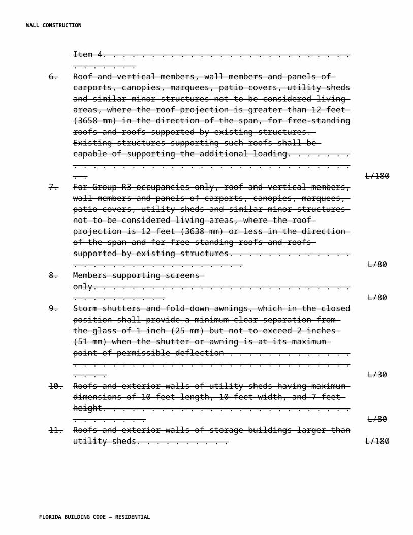
steel, thickness or gauge of material, and galvanizing to ASTM G 60 as a minimum. This certification requirement shall be satisfied by submitting by an approved independent laboratory to the product control division.
R4409.6.17.2.3 Fabrication.
R4409.6.17.2.3.1 Manufacturers of prefabricated wood truss assemblies shall obtain a valid certificate of competency from the authority having jurisdiction.
R4409.6.17.2.3.2 Each truss shall bear the fabricators stamp on a web member and 75 percent shall be placed so as to be clearly visible after erection and before placement of ceiling.
R4409.6.17.2.3.3 Multiple member girder trusses shall be predrilled at the truss plant for connection bolts only. Hanger bolt holes shall be drilled on-site on location indicated on approved drawings.
R4409.6.17.2.3.4 Each manufacturer or fabricator shall retain the services of applicable organizations among those listed below for monthly inspections of the lumber grade used in fabrication. Following each inspection, a report shall be submitted by the inspection agency to the authority having jurisdiction. All inspection agencies providing any type of inspection services shall be approved by the authority having jurisdiction.
For Pine:
Southern Pine Inspection Bureau or Timber Products Inspection Inc. or other grading agencies with appropriate jurisdiction.
For Douglas Fir, Hem-Fir or Fir-Larch:
Western Wood Products Association or West Coast Lumber Inspection Bureau. Timber Products Inspection Inc. or other grading agencies with appropriate jurisdiction.
R4409.6.17.2.3.5 In addition, the fabricator shall employ an approved testing laboratory to conduct inspections of fabrication compliance. Such inspections shall be made unannounced and at random at least once a month. Following each inspection, a report on approved forms shall be submitted by the laboratory to the authority having jurisdiction and such reports shall bear the date, signature and seal of the supervising Florida-registered architect or professional engineer.
R4409.6.17.2.3.6 When there is evidence of noncompliance with the provisions for fabrication set forth in this paragraph or with the approved plans, the authority having jurisdiction may require the inspection laboratory to make additional jobsite or plant inspections.
R4409.6.17.2.3.7 The authority having jurisdiction may require load testing on noncomplying wood trusses. The test results shall be reported to the authority having jurisdiction.
R4409.6.17.2.3.8 Failure of units tested or receipt of inspection reports indicating fabrication
WALL CONSTRUCTION
FLORIDA BUILDING CODE — RESIDENTIAL
not in accordance with approved truss design drawings, or failure to submit required inspection and/or test reports, shall be cause for suspension or revocation of the certificate of competency of the manufacturer or fabricator.
R4409.6.17.2.4.4 At gable ends, this diaphragm shall be designed to transmit lateral loads imposed on the gable to roof diaphragms and/or ceiling diaphragms where available. Where the wall supporting the gable is not designed to withstand lateral loads independent of the gable (by using shear walls or other methods), anchorage of the gable to the wall shall be designed to transmit the loads from the wall to the bracing and the bracing designed to transmit the lateral loads from the gable and wall to the roof diaphragms and/or ceiling diaphragms where available. Ceiling diaphragms that provide lateral support at gable walls shall be designed by the architect or professional engineer of record, and shall have continuous bottom chord bracing, end restraints, intermediate restraints and conditions so as to sufficiently transfer the lateral loads at the top of the gable end walls to the intersecting shear walls. In no case shall the rigid ceiling as defined in Section R4409.6.17.1.2 be used as an integral part of the system needed for lateral bracing of the gable end walls.
SECTION R4409.8HIGH-VELOCITY HURRICANE ZONES —
ANCHORAGE
R4409.8.1 Anchorage shall be continuous from the foundation to the roof and shall satisfy the uplift requirements of Section R4403.9.
R4409.8.2 Joists.
R4409.8.2.1 Fire-cuts into a masonry wall shall be anchored to the concrete beam on which they bear.
R4409.8.2.2 Such anchors shall be spaced not more than 4 feet (1219 mm) apart and shall be placed at opposite ends across the building on the same run of joists.
R4409.8.3 Joists shall be nailed to bearing plates, where such plates occur, to each other where continuous at a lap and to the studs where such studs are contiguous; and ceiling joists shall be nailed to roof rafters where contiguous.
R4409.8.4 Every roof rafter and/or roof joist shall be anchored to the beam or studs on which they bear, and roof rafters opposing at a ridge shall be anchored across the ridge as set forth in Section R4409.8.6.
R4409.8.5 Anchorage to concrete.
R4409.8.5.1 Anchorage designed to resist uplift forces, securing wood to concrete shall be steel straps embedded in the concrete minimum of 4 inches (102 mm) with hooking devices to top steel of tie beam designed to withstand the uplift forces set forth by the design professional.
WALL CONSTRUCTION
FLORIDA BUILDING CODE — RESIDENTIAL
Straps shall be an approved product. All anchors and related fasteners shall be galvanized.
R4409.8.5.2 As an alternate to using the straps described in this section, the building official may approve other anchorage submitted by a Florida-registered professional engineer or a Florida-registered architect, proficient in structural design, provided that the information set forth in Section R4409.8.7(1), (2) and (3) submitted in connection with such anchors and such anchors and the proposed assembly otherwise comply with the requirements of this code.
R4409.8.6 Anchorage to wood.
R4409.8.6.1 Anchorage designed to resist uplift forces, securing wood to wood shall be steel straps nailed to each member and shall be designed to resist uplift forces set forth by the design professional. Straps shall be an approved product. All anchors and relative nails shall be galvanized.
R4409.8.6.2 As an alternate to using straps described in this section, the building official may approve other anchorage submitted by a Florida-registered architect or a Florida registered professional engineer, proficient in structural design, provided that the information set forth in Sections R4409.8.7(1), (2) and (3) submitted in connection with such anchors and such anchors and the proposed assembly otherwise comply with the requirements of this code.
R4409.8.7 Testing of anchoring. Anchoring required by R4409.8. and R4409.8.6 shall be tested under the following criteria: 1. Concrete to wood straps: Minimum design uplift load 700 pounds (3114 N), with 4 16d nails with upper end bent over truss chord and nailed. Nails shall be clinched. Anchors shall have devices to hook into upper tie beam steel and embedded a minimum of 4 inch (102 mm) in concrete. 2. Wood to wood straps: Minimum design uplift 700 lb (3114 N) with four 16d nails in each member. 3. Other anchors: Minimum design uplift 700 pounds (3114 N). 4. The criteria stated in Sections R4409.8.7(1), (2) and (3) above are minimum requirements for Product Approval. Anchor design and uplift forces shall be approved site for the inspector to.
SECTION R4409.9HIGH-VELOCITY HURRICANE ZONES —
SHEATHING
R4409.9.1 Floor sheathing.
R4409.9.1.3 Square-edged or spaced subflooring may be used only under a finish floor having a strength equal to or greater than 1/2 inch (12.7 mm) tongue-and-groove wood strip flooring; and under finish floors of less strength, a tongue-and-groove or plywood subfloor shall be required.
R4409.9.1.4 Lumber subflooring shall be not less than 5/8-inch (17 mm) thick when joists are
WALL CONSTRUCTION
FLORIDA BUILDING CODE — RESIDENTIAL
spaced no more than 16 inches (406 mm) on center nor less than 3/4-inch (19 mm) thick when joists are spaced no more than 24 inches (610 mm) on center. End joints shall be on joists, joints shall be staggered and parallel to the joists, and ends at walls and similar places shall be supported by a ribbon or by blocking.
R4409.9.1.5 Plywood subfloors of C-D grade or Underlayment grade bonded to wood joist using adhesives meeting the requirements of ASTM D 3498 shall be applied as indicated in Section R4409.9.1.6.
R4409.9.1.6 Plywood subflooring shall be continuous over two or more spans with face grain perpendicular to the supports. The allowable spans shall not exceed those set forth in Table R4409.9.1.6.
TABLE R4409.9.1.6PLYWOOD SUBFLOOR1
PANEL SPAN RATING2 MAXIMUM PLYWOOD SPAN (IN.)3
32/16 16440/20 20448/24 24
For SI: 1 inch = 25.4 mm.Notes:1. These values apply for Sheathing C-D and C-C grades only. Spans shall be limited to values shown, and reduced for the possible effects of concentrated loads.2. Span Ratings shall appear on all panels.3. Plywood edges shall have approved tongue-and-groove joints or shall be supported with blocking unless 1/4 inch minimum thickness underlay is installed or 1/2 inch of approved cellular or lightweight concrete is installed or unless finish floor is 1-inch nominal woodstrip. Allowable uniform load based on deflection of 1/360 of span is 100 pounds per square foot.4. May be 24 inches if nominal 1-inch wood strip finish floor is laid at right angles to joists.
R4409.9.1.6.1 Plywood panels shall be nailed to supports with 6d common nails when up to 1/2 inch (13 mm) thick, 8d common nails when 19/32 to 3/4 inch (15 to 19 mm) thick and 10d common nails or 8d ring shank when 11/8 inches (29 mm) thick.
R4409.9.1.6.2 Nail spacing shall be 6 inches (152 mm) o.c. at panel edges and 10 inches (254 mm) o.c. at intermediate supports
R4409.9.1.8 Flooring shall be nailed with 8d common nails up to 3/4 inch (19 mm) thick, and 10d common nails or 8d ring shank nails when greater than 3/4 inch (19 mm) thick up to 11/8 inches (29 mm) thick.
R4409.9.1.8.1 Nails shall be hand driven 8d common nails [(0.131 inch (3.3 mm) diameter by 21/2 (inches (63.5 mm) long with 0.281 inch (7.1 mm) diameter full round head)] or power driven 8d nails of the same dimensions (0.131 inch diameter by 21/2 inches long with 0.281
WALL CONSTRUCTION
FLORIDA BUILDING CODE — RESIDENTIAL
inch diameter full round head). Nails of a smaller diameter or length may be used only when approved by an architect or licensed engineer and only when the spacing is reduced accordingly.
R4409.9.1.8.2 Nails shall be hand driven 10d common nails (0.148 inch (3.8 mm) diameter by 3 inch (76 mm) long with 0.312 inch (7.9 mm) diameter full round head) or power driven 10d nails of the same dimensions (0.148 inch diameter by 3 inch long with 0.312 inch diameter full round head). Nails of a smaller diameter or length may be used only when approved by an architect or licensed engineer and only when the spacing is reduced accordingly.
R4409.9.1.9 Nail spacing shall be 6 inches (152 mm) on center at panel edges and 10 inches (254 mm) on center at intermediate supports.
R4409.9.1.10 Flooring shall be nailed with 8d common nails not less than two in each board at each support.
R4409.9.1.11 Floors for heavy timber buildings shall be sheathed as specified for mill floors in Section R4409.9.13.
R4409.9.1.12 Flooring shall not extend closer than 1/2 inch (12.7 mm) from masonry walls.
TABLE R4409.9.1.13ALLOWABLE SPAN FOR PLYWOOD COMBINATION SUBFLOOR
UNDERLAYMENT1
(SINGLE FLOOR PANELS)
SPECIES GROUPS MAXIMUM PLYWOOD SPAN (IN.)2,3
164 204 24 481 1/2" 5/8" 3/4"2,3 5/8" 3/4" 7/8"4 3/4" 7/8" 1"1,2 and 3 1 1/8"
For SI: 1 inch = 25.4 mm.Notes:1. Applicable underlayment grade, C-C (plugged) and all grades of sanded Exterior type plywood.2. Spans shall be limited to values shown, and reduced for the possible effects of concentrated loads.3. Allowable uniform load based on deflection of 1/360 of span is 100 pounds per square foot except that total load for 48" on center is 65 pounds per square foot. Plywood edges shall have approved tongue-and-groove joints or shall be supported with blocking unless 1/4 inch minimum thickness underlay is installed or 1/2 inch of approved cellular or lightweight concrete is placed over the subfloor and the sheathing is rated for Exposure 1.4. If a wood finish floor is laid perpendicular to the joists or supports, thickness shown
WALL CONSTRUCTION
FLORIDA BUILDING CODE — RESIDENTIAL

for 16-inch and 20-inch spans may be used for 24-inch spans.
R4409.9.1.16 Diaphragm boundaries. All floor sheathing acting as a diaphragm shall be attached to a minimum 2-inch (51 mm) thick nominal nailer with its depth equal to or one size greater than the intersecting top chord. The nailer shall be connected to the wall to resist the gravity loads from the floor, wind pressure/suction from the exterior wall and the diaphragm forces. The floor sheathing shall be attached to the nailer to resist the wind pressure/suction from the exterior wall and the diaphragm forces.
R4409.9.2 Roof sheathing.
R4409.9.2.1 Wood roof sheathing shall be boards or shall be plywood.
R4409.9.2.2 Board roof sheathing shall have a net thickness of not less than 3/4 inch (19 mm) when the span is not more than 28 inches (711 mm) or 5/8-inch (17 mm) when the span is not more than 24 inches (610 mm), shall have staggered joints and shall be nailed with 8d common nails not less than two in each 6-inch (152 mm) board nor three in each 8 inch (203 mm) board at each support.
R4409.9.2.3 Plywood roof sheathing shall be rated for Exposure 1, have a minimum nominal thickness of 19/32 inch (21 mm) and shall be continuous over two or more spans with face grain perpendicular to supports. Roof sheathing panels shall be provided with a minimum of 2x4 edgewise blocking at all horizontal panel joints with edge spacing in accordance with manufacturer's specifications, for a distance at least 4 feet (1219 mm) from each gable end. The allowable spans shall not exceed those set forth in Table R4409.9.2.3.
TABLE R4409.9.2.3ALLOWABLE SPAN FOR PLYWOOD ROOF SHEATHING1
PANEL SPAN RATING2 MAXIMUM SPAN IF MAXIMUM SPAN WITHOUTBLOCK OR OTHER EDGE EDGE SUPPORT (IN.)SUPPORTS (IN.)32/16 24 2440/20 40 3248/24 48 36
For SI: 1 inch = 25.4 mm.Notes:1. Values apply to sheathing grade, C-C and C-D panels.2. Span Rating appears on all C-C and C-D panels.
R4409.9.2.4 Plywood panels shall be nailed to supports with 8d ring shank nails.
WALL CONSTRUCTION
FLORIDA BUILDING CODE — RESIDENTIAL
R4409.9.2.5 Nail spacing shall be 6 inches (152 mm) on center at panel edges and at intermediate supports. Nail spacing shall be 4 inches (102 mm) on center at gable ends with either 8d ring shank nails or 10d common nails.
R4409.9.2.5.1 Nails shall be hand driven 8d ring shank or power driven 8d ring shank nails of the following minimum dimensions: (a) 0.113 inch (2.9 mm) nominal shank diameter, (b) ring diameter of 0.012 inch (0.3 mm) over shank diameter, (c) 16 to 20 rings per inch, (d) 0.280 inch (7.1 mm) full round head diameter, (e) 23/8 inch (60.3 mm) nail length. Nails of a smaller diameter or length may be used only when approved by an architect or licensed engineer and only when the spacing is reduced accordingly.
R4409.9.2.5.2 Nails at gable ends shall be hand driven 8d ring shank or power driven 8d ring shank nails of the following minimum dimensions: (a) 0.113 inch (2.9 mm) nominal shank diameter, (b) ring diameter of 0.012 inch (0.3 mm) over shank diameter, (c) 16 to 20 rings per inch, (d) 0.280 inch (7.1 mm) full round head diameter, (e) 23/8 inch (60.3 mm) nail length or as an alternative hand driven 10d common nails [(0.148 inch (3.8 mm) diameter by 3 inches (76 mm) long with 0.312 inch (7.9 mm) diameter full round head)] or power driven 10d nails of the same dimensions [0.148 inch (3.8 mm) diameter by 3 inches (76 mm) long with 0.312 inch (8 mm) diameter full round head]. Nails of a smaller diameter or length may be used only when approved by an architect or professional engineer and only when the spacing is reduced accordingly. Other products with unique fastening methods may be substituted for these nailing requirements as approved by the building official and verified by testing.
R4409.9.2.5.3 Other products with unique fastening methods may be substituted for these nailing requirements as approved by the building official and verified by testing.
R4409.9.2.6 Roof sheathing for heavy timber construction shall comply with Section R4409.6.13 of this code.
R4409.9.2.7 Diaphragm boundaries. All roof sheathing acting as a diaphragm shall be attached to a minimum 2-inch (51 mm) thick nominal member with its depth equal to or one size greater than the intersecting top chord. This shall be achieved with a continuous structural subfascia, fascia or blocking at 4 inches (102 mm) on center with nails as required for the appropriate thickness of sheathing.
R4409.9.2.8 When existing roofs are reroofed to the point that the existing roofing is removed down to the sheathing, the existing roof sheathing shall be re-nailed with 8d common nails [(0.131 inch (3.3 mm) diameter by 21/2 inches (63.5 mm) long with 0.281 inch (7.9 mm) diameter full round head)]. Nail spacing shall be 6 inches (152 mm) on center at panel edges, 6 inches (152 mm) on center at intermediate supports and where applicable 4 inches (102 mm) on center over gable ends and subfascia. Existing fasteners may be used to achieve such minimum spacing.
R4409.9.3 Storm sheathing. Exterior stud walls shall be sheathed to resist the racking load of wind as set forth in Section R4403.9 and the concentrated loads that result from hurricane-generated wind-borne debris as set forth in Section R4403.16 of this code and shall be at a
WALL CONSTRUCTION
FLORIDA BUILDING CODE — RESIDENTIAL
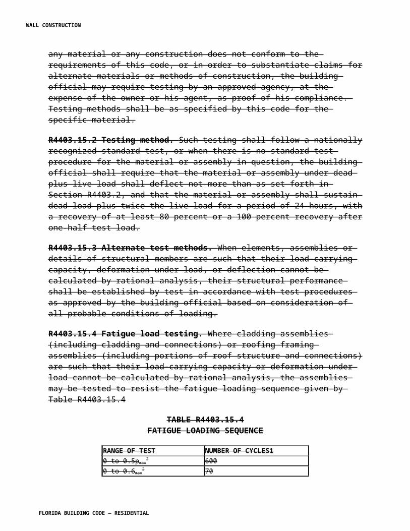
minimum any of the following types:
1. Tightly fitted, diagonally placed boards not less than 5/8 inch (17 mm) thickness, nailed with three 8d common nails to each support for 1 inch by 6 inch (25 mm by 152 mm) boards and four 8d common nails for 1 inch by 8 inch (25 mm by 203 mm) boards.
2. Wall sheathing shall be plywood, or Product Approved structural panel, rated Exposure 1 with a minimum thickness of 19/32 inch (15 mm) and shall be applied to studs spaced not more than 16 inches (406 mm) on center. Wall sheathing shall be continuous over three or more supports and shall be nailed to such supports with 8d common nails. Nail spacing shall not exceed 6 inches (152 mm) on center at panel edges and all intermediate supports. Nail spacing shall be 4 inches (102 mm) on center at corner studs, in all cases.
3. When plywood panel, or product approved structural panel, sheathing is used, building paper and diagonal wall bracing can be omitted.
4. When siding such as shingles nailed only to plywood or product approved structural panel sheathing, the panel shall be applied with face grain across studs.
R4409.9.4 Exterior wall cladding.
R4409.9.4.1 Plywood, if protected with stucco, may serve for both sheathing and exterior cladding provided:
1. The panel thickness shall be not less than 19/32 inch (15 mm) and Texture 1-11 panels, and the supporting studs shall be spaced not more than 16 inches (406 mm) o.c.
2. All joints shall be backed solidly with 2-inch (51 mm) nominal blocking or studs or the joints shall be lapped horizontally or otherwise watertight.
3. Nailing shall be as set forth in Section 4409.9.3(2).
R4409.9.4.2 Where storm sheathing is provided in accordance with Section R4409.9.3, exterior cladding may be one of the following:
1. Wood siding shall be installed according to its Product Approval.
2. Wood shingles or shakes attached to the storm sheathing, and/or to nailing boards or shingle backer securely attached to the storm sheathing. The minimum thickness of wood shingles or shakes between nailing boards shall be 3/8 inch (9.5 mm).
3. Hardboard of siding quality for exterior use shall be applied in accordance with the Product Approval.
WALL CONSTRUCTION
FLORIDA BUILDING CODE — RESIDENTIAL
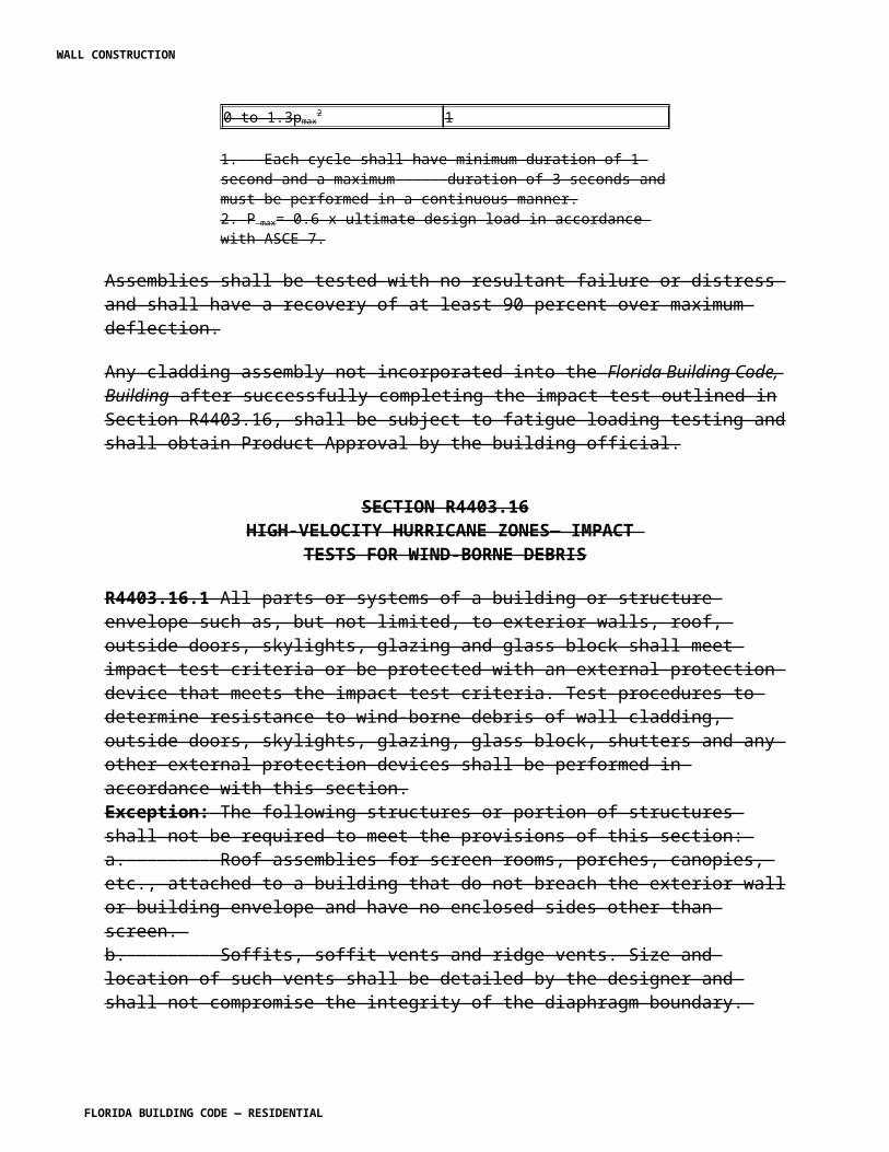
SECTION R4409.11HIGH-VELOCITY HURRICANE ZONES —
CONNECTORS
R4409.11.1 The allowable loads on all types of connectors shall be as set forth in the standards listed in Section R4409.1.4 and Table R4409.11.1.
R4409.11.2 Nails, bolts and other metal connectors that are used in locations exposed to the weather shall be galvanized or otherwise corrosion resistant.
R4409.11.3 In general, nails shall penetrate the second member a distance equal to the thickness of the member being nailed thereto. There shall be not less than two nails in any connection.
R4409.11.4 Except for wood-based structural-use panels and other laminated members manufactured under technical control and rigid inspection, gluing shall not be considered an acceptable connector in lieu of the connectors herein specified.
R4409.11.5 Safe loads and design practice for types of connectors not mentioned or fully covered herein shall be determined by the building official before approval.
SECTION R4409.12HIGH-VELOCITY HURRICANE ZONES —
WOOD SUPPORTING MASONRY
R4409.12.1 Wood shall not support masonry or concrete except as permitted in Sections R4409.12.2 and R4409.12.3.
R4409.12.2 Wood foundation piles may be used to support concrete or masonry.
SECTION R4409.13HIGH-VELOCITY HURRICANE ZONES —
PROTECTION OF WOOD
R4409.13.1 Wood piles shall be treated with preservatives as set forth in Section R4404.7.1.2.
R4409.13.2 Preservative treated or durable species wood.
R4409.13.2.1 All wood used in areas of building or structures where the climatic condition is conducive to deterioration which would affect the structural safety shall be treated in an approved method with an approved preservative or shall be of an approved durable species.
R4409.13.2.2 All wood in contact with or embedded in the ground that supports of permanent
WALL CONSTRUCTION
FLORIDA BUILDING CODE — RESIDENTIAL
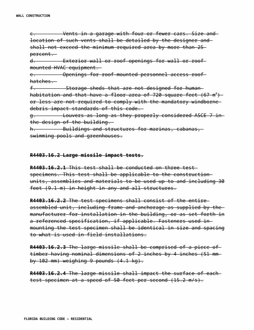
structures shall be approved pressure-treated wood suitable for ground contact use.
Exceptions: 1. Naturally durable wood or pressure-treated wood may be used in contact with the ground for support of structures other than buildings and walking surfaces. 2. Untreated wood may be used for supports where entirely below water level and continuously submerged in fresh water.
R4409.13.2.3 Sleepers and sills on concrete slabs in contact with the ground, wood joists and the underside of wood structural floors without joists less than 18 inches (457 mm) above ground; or wood girders less than 12 inches (305 mm) from exposed ground within the crawl space under buildings, shall be treated in an approved method with an approved preservative, or shall be of an approved durable species.
R4409.13.2.4 All wood not separated from and/or in direct contact with concrete masonry, including sills, sleepers, plates, posts, columns, beams, girders and furring; shall be treated in an approved method with and approved preservative, or shall be of an approved durable species.
R4409.13.2.5 The expression "pressure-treated wood" refers to wood meeting the retention, penetration and other requirements applicable to the species, product, treatment and conditions of use in the approved standards of the American Wood Preservers Association (AWPA) and Quality Control Program for Softwood Lumber, Timber and Plywood Pressure Treated with Water-borne Preservatives for Ground Contact Use in Residential and Light Commercial Foundations for the American Wood Preservers Bureau.
R4409.13.2.6 The expression "durable wood" refers to the heartwood of the following species with the exception that an occasional piece with corner sapwood may be included if 90 percent or more of the width of each side on which it occurs is heartwood:
Decay resistant: Redwood, Cedars, Black Locust.Termite Resistant: Redwood, Bald and Eastern Red Cedar.
R4409.13.2.7 Where durable species of wood are used as structural members in buildings and structures, the stress grade shall be not less than that required in Section R4409.4.
R4409.13.2.8 When wood pressure treated with a water-borne preservative is used in enclosed locations where drying in service cannot readily occur, such wood shall have a moisture content of 19 percent or less before being covered with insulation, interior wall finish, floor covering or other material.
R4409.13.2.9 All wood framing less than 8 inches (203 mm) from exposed earth in exterior walls that rest on concrete or masonry foundations shall be approved naturally durable species or pressure-treated wood.
R4409.13.2.10 All posts, poles and columns embedded in concrete which is in contact with ground and supporting permanent structures shall be approved pressure treated wood suitable
WALL CONSTRUCTION
FLORIDA BUILDING CODE — RESIDENTIAL
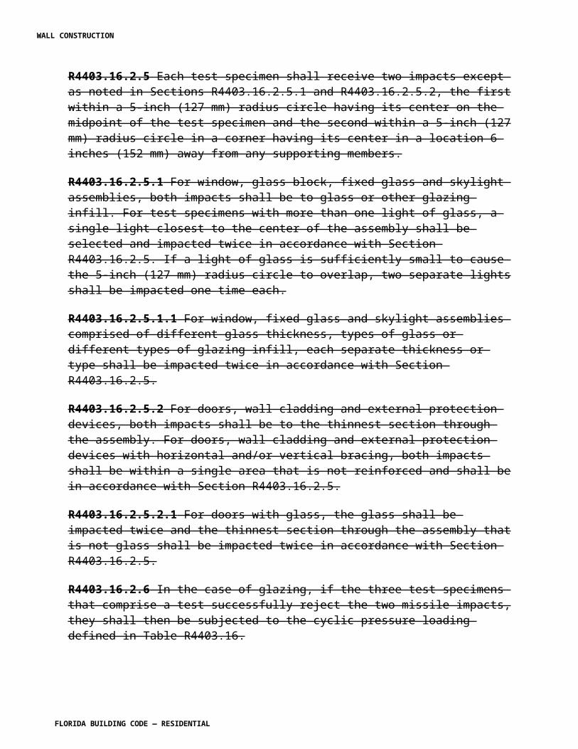
for ground contact use except naturally durable wood may be used for posts, poles and columns embedded in concrete for structures other than buildings and walking surfaces or in structures where wood is above ground level and not exposed to the weather.
R4409.13.2.11 For conditions not specifically covered, compliance with American Forest & Paper Product Association Wood Construction Data #6, Design of Wood Frame Structures for Permanence, shall be deemed as compliance with this code.
R4409.13.3 Ventilation.
R4409.13.3.1 Ventilation of crawl spaces. Crawl spaces under buildings without basements shall be ventilated by approved mechanical means or by openings in foundation walls. Ventilation openings shall be covered with a corrosion-resistant wire mesh with openings not greater than 1/16 inch (1.6 mm).
R4409.13.3.1.1 Where practicable, ventilating openings shall be arranged on three sides.
R4409.13.3.1.2 The minimum total area of ventilating openings shall be 2 square feet (0.19 m2) for each 15 linear feet (4.6 m) or a fraction thereof of exterior wall. Such opening need not be placed in the front of the building. Where mechanical ventilation is used, the ventilation rate shall be at least six air changes per hour.
R4409.13.3.2 Ventilation of attic spaces. Attic space between ceiling joists and roof rafters shall be effectively cross-ventilated by approved mechanical means or with vent openings. The ratio of total net free ventilating area to the area of the ceiling shall be not less than 1/150.
Exception: The venting ratio may be reduced to 1/300 where at least 50 percent of the installed ventilating area is provided by a ventilation system located in the upper portion of the space to be ventilated [within 18 inches (457 mm) of ridge]. The balance of the required ventilation shall be provided by eave or cornice vents.
R4409.13.3.2.1 Where practical, ventilating openings shall be arranged on three sides.
R4409.13.3.2.2 Where mechanical ventilation is used, the ventilation rate shall be at least six air changes per hour.
R4409.13.3.2.3 All openings into the attic space of any habitable building shall be covered with screening, hardware cloth or equivalent to prevent the entry of birds, squirrels, rodents, etc. The openings therein shall not exceed 1/8 inch (3.2 mm).
R4409.13.3.2.4 For existing structures that were built before 1992 without soffit ventilation, and where in the opinion of the building official the soffit ventilation would be impossible or impractical to install, the building official may determine the extent to which the existing structure shall be made to conform to the requirements of this section.
R4409.13.3.2.5 Unvented attic assemblies. Unvented attic assemblies shall be permitted if all
WALL CONSTRUCTION
FLORIDA BUILDING CODE — RESIDENTIAL
the following conditions are met: 1. The unvented attic space is completely contained within the building thermal envelope. 2. No interior vapor retarder is installed on the ceiling side (attic floor) of the unvented attic assembly. 3. Where wood shingles or shakes are used, a minimum continuous ¼ inch (6 mm) vented air space separates the shingles or shakes from the roofing underlayment. 4. One of the following shall be met, depending on the air permeability of the insulation under the structural roof sheathing: a. Air-impermeable insulation only. Insulation shall be applied in direct contact to the underside of the structural roof sheathing. b. Air-permeable insulation only. In addition to air-permeable insulation installed directly below the structural sheathing, at least R-5 rigid board or sheet insulation shall be installed directly above the structural roof sheathing for condensation control. c. Air-impermeable and air-permeable insulation. At least R-5 air-impermeable insulation shall be applied in direct contact to the underside of the structural roof sheathing for condensation control. The air-permeable insulation shall be installed directly under the air-impermeable insulation.
R4409.13.4 Debris.
R4409.13.4.2 In buildings or portions thereof having wood first-floor systems, all wood forms which have been used in placing concrete, if within the ground or less than 18 inches (457 mm) above the ground, shall be removed before the building is occupied or used for any purpose.
R4409.13.4.3 Loose or casual wood shall not be stored in direct contact with the ground under any building, and this space must be thoroughly cleaned of all wood and debris.
TABLE R4409.13.1NAIL CONNECTION FOR WOOD MEMBERS
CONNECTION COMMON NAILS NUMBER OR SPACINGJoists to sill or girder, toe nail 16d 2Bridging to joist, toe nail 8d 2 each end1" x 6" subfloor or less to each joist, face nail 8d 2Over 1" x 6" subfloor to each joist, face nail 8d 3 + 1 for each size increase2" subfloor to joist or girder, blind and face nail 16d 2Sole plate to joist or blocking, face nail 16d 16" o.c.Top or sole plate to stud, end nailed 16d 2Stud to sole plate, toe nail 3d 3 or 2 16dDoubled studs, face nail 16d 24" o.c.Doubled top plates, face nail 16d 16" o.c.Top plates, laps and intersections, face nail 16d 2Continuous header, two pieces 16 d 16" o.c. along each edge
WALL CONSTRUCTION
FLORIDA BUILDING CODE — RESIDENTIAL
Ceiling joists to plate, toe nail 16d 2Continuous header to stud, toe nail 16d 3Ceiling joists, laps over partitions, face nail 16d 3Ceiling joists to parallel rafters, face nail 16d 3Rafter plate, toe nail 16d 31" x 6" sheathing or less, to each bearing, face nail 8d 2Over 1" x 6" sheathing, to each bearing, face nail 8d 3 + 1 for each size increaseBuilt-up corner studs, face nail 16d 30" o.c.Built-up girders and beams 20d 32" o.c. at top and bottom and staggered, 2 at ends and at each splice2 inch planks 16d 2 each bearing
For SI: 1 inch = 25.4 mm.Note: In spacing specifications, o.c. means "on center."
R4409.13.6.1 The building official shall inspect existing buildings having wood-stud exterior walls for which application for a permit for exterior wall coverings is made and shall have the authority to order the uncovering of structural elements for inspection and to require necessary repairs as a part of such approval for a permit, or may order demolition.
SECTION R4409.15HIGH-VELOCITY HURRICANE ZONES —
WOOD FENCES
R4409.15.1 Wood fences, so located on a property that by zoning regulations they cannot be used as a wall of a building, shall be constructed to meet the minimum specifications in Sections R4409.15.2 and R4409.15.3.
R4409.15.2 Fences not exceeding 6 feet (1829 mm) in height, shall be constructed to meet the following minimum requirements: from nominal 4 x 4 x 8 feet (2438 mm) long posts No. 2 Grade or better spaced 4 feet (1219 mm) on center, and embedded 2 feet (610 mm) into a concrete footing 10 inches (254 mm) in diameter and 2 feet (610 mm) deep.
R4409.15.3 Fences not exceeding 5 feet (1524 mm) or 4 feet (1219 mm) in height shall be constructed as provided in Section R4409.15.2, except that the spacing of posts may be increased to 5 feet (1524 mm) and 6 feet (1829 mm) on center for these heights, respectively.
SECTION R4409.17HIGH-VELOCITY HURRICANE ZONES —
WOOD BLOCKING
R4409.17.1 General.
R4409.17.1.1 Blocking is defined as wood pieces attached to the roof deck or to each other for
WALL CONSTRUCTION
FLORIDA BUILDING CODE — RESIDENTIAL
the purpose of securing roof membrane or accessories.
R4409.17.1.2 Wood blocking attachment for buildings greater than 40 feet (12.2 m) in height must be designed by a registered architect or professional engineer.
R4409.17.1.3 Wood blocking attachment for lightweight insulating concrete, gypsum concrete, cementitious wood fiber and cellular concrete decks shall be designed by a registered architect or licensed engineer. The decks themselves shall not be used as a wood blocking attachment substrate.
R4409.17.1.4 Wood blocking shall not be less than nominal 2x6. The maximum unsupported overhang shall be 2 inches (51 mm). When the maximum overhang is employed, a nominal 2x8 blocking shall be installed.
R4409.17.1.5 In recover applications, wood blocking may be reduced to nominal 1 inch (25 mm), providing the attachment is secured in compliance with this code.
R4409.17.1.6 Sound wood blocking may be reused in a recover or reroof application, providing the attachment is secured in compliance with the requirements of this code.
R4409.17.1.7 A fastener shall be placed within 3 inches (761 mm) of the end of each section of wood blocking and a 1/4 inch (6 mm) gap shall be left between each section of wood blocking. No piece of wood shall have less than two fasteners.
R4409.17.1.8 Fasteners other than nails shall be predrilled prior to attachment and countersunk to be flush with the surface of the wood blocking.
R4409.17.1.9 Wood shall be protected according to Section R4409.13.
R4409.17.1.10 Powder actuated fasteners shall not be used in wood blocking attachment.
R4409.17.2 Attachment to masonry block and concrete.
R4409.17.2.1 Prior to the installation of wood blocking to standard weight masonry block, the two top courses shall be solidly filled with concrete or a tie beam shall be provided as required by this code.
R4409.17.2.2 The fastener's average withdrawal resistance per lineal foot shall be not less than 250 pounds per foot (3649 N/m) after the application of a 4:1 safety factor.
R4409.17.2.3 The pullover value of the proposed fastener though the wood blocking shall be not less than 125 percent of the design load of the proposed fastener. If less, a larger bearing washer shall be added to the fastener assembly to meet this requirement. Wood blocking thickness shall be not less than 11/2 inch (38 mm) if a bearing washer is required.
[S5016 AS]
WALL CONSTRUCTION
FLORIDA BUILDING CODE — RESIDENTIAL
Section R4410. Change to read as follows:
SECTION R4410HIGH-VELOCITY HURRICANE ZONES —
GLASS AND GLAZING
R4410.1 General Refer to Chapter 24 of the Florida Building Code, Building .
R4410.1.1 Exterior wall cladding, surfacing and glazing, where provided, shall be as set forth in Sections R4410 through R4415.
R4410.1.2 Exterior wall cladding, surfacing and glazing shall be designed and constructed to sufficiently resist the full pressurization from the wind loads prescribed in Section R4403 and the concentrated loads that result from hurricane-generated wind-borne debris.
1. Exterior wall cladding, surfacing and glazing, within the lowest 30 feet (9.1 m) of the exterior building walls shall be of sufficient strength to resist large missile impacts as outlined in Section R4403. 2. Exterior wall cladding, surfacing and glazing located above the lowest 30 feet of the exterior building walls shall be of sufficient strength to resist small missile impacts as outlined in Section R4403.
Exception: Exterior wall cladding, surfacing and glazing when protected by fixed, operable or portable shutters or screens which have Product Approval to resist full pressurization from wind loads as well as large and small missile impacts as outlined in Section R4403, without deforming to the point where the substrate being protected is compromised.
R4410.1.4 All exterior wall cladding, surfacing, garage doors, skylights, operative and inoperative windows shall have Product Approval.
SECTION R4410.2HIGH-VELOCITY HURRICANE ZONES —
WINDOWS, DOORS, GLASS AND GLAZING
R4410.2.1 General.
R4410.2.1.1 Windows, doors, glass and glazing shall be as set forth in this section.
R4410.2.1.2 Glass shall comply with ASTM C 1036 requirements for flat glass Type I and
WALL CONSTRUCTION
FLORIDA BUILDING CODE — RESIDENTIAL
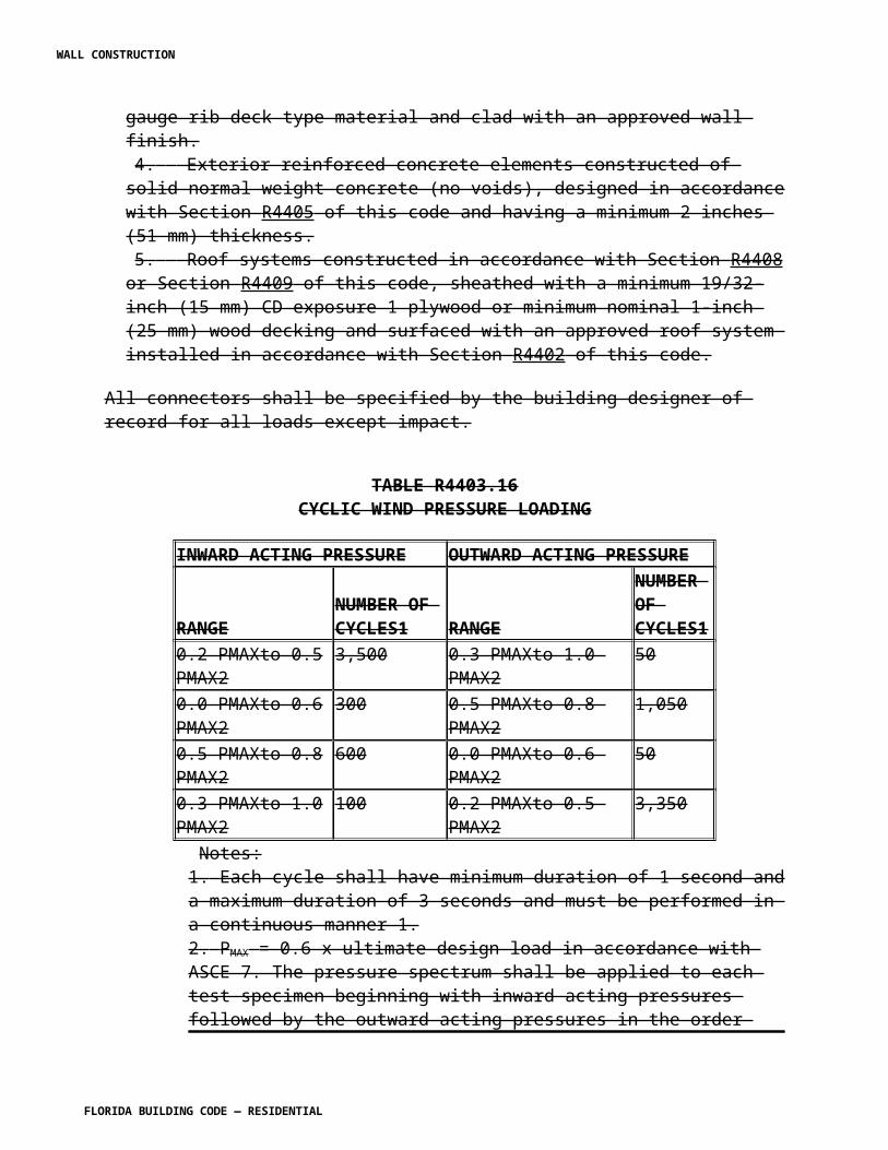
II and GSA DD-G-451c Standard for Glass, Flat and Corrugated, for Glazing Mirrors and Other Uses .
R4410.2.1.7 Installed glass shall not be less than single strength B quality unless otherwise approved by the building official, and where edges are exposed they shall be seamed or ground.
R4410.2.1.8 Where a light of glass is of such height above grade that the top 50 percent or more is in a zone of greater wind load, the area of the entire light shall be limited as for the greater height above grade.
R4410.2.1.9 Replacement of any glazing or part thereof shall be designed and constructed in accordance with Florida Existing Building Code .
R4410.2.1.10 Replacement of glazing of more than one light or more than 30 percent of the total area glazed shall conform to the requirements of the section.
R4410.2.1.11 Fixed glazing used as an exterior component shall require Product Approval. Comparative analysis in compliance with R4410.2.3.2.6 by a Florida licensed engineer or architect may be accepted when the actual pressure and geometry conditions differ from the conditions shown in the approval.
R4410.2.2 Fixed glass in exterior walls.
R4410.2.2.1 Limits of size of glass.
R4410.2.2.1.1 The minimum thickness of annealed float glazing materials used in exterior walls shall be determined and shall not be less than as set forth in ASTM E 1300.
R4410.2.2.1.2 For glazing materials other than annealed float, use the glazing material resistance factor used in ASTM E 1300.
R4410.2.2.1.3 Corrugated glass and other special glass shall be limited to spans determined by analysis and test to resist the loads set forth in Section R4403 based on fiber stresses not exceeding 4,000 psi (27.58 MPa).
R4410.2.2.1.4 Glass block shall have Product Approval.
R4410.2.3 Doors and operative windows in exterior walls.
R4410.2.3.1 Design and approval.
R4410.2.3.1.1 The design and approval of sliding doors, swinging doors and operative windows in exterior walls, including the supporting members shall be based on the proposed use-height above grade in accordance with Section R4403 .
WALL CONSTRUCTION
FLORIDA BUILDING CODE — RESIDENTIAL
R4410.2.3.1.2 Maximum glass sizes shall comply with ASTM E 1300.
R4410.2.3.1.4 The architect or professional engineer of record shall be required to specify the design wind pressure, determined in accordance with Section R4403, for all garage doors, skylights operative windows and fixed glazing. The design wind pressure for each component of the exterior building surface, shall be incorporated into the building design drawing so as to allow the respective manufacturer to size the prefabricated assembly for the proper wind pressures.
R4410.2.3.1.5 Exterior garage doors shall be designed and constructed to actively or passively lock in the closed position when subjected to a uniform lateral pressure in excess of 50 percent of the design wind pressure as prescribed in Section R4403.
R4410.2.3.1.6 The architect or professional engineer of record shall be required to detail on the drawings submitted for permit, rough opening dimensions, supporting framework, method of attachment and waterproofing procedures for all garage doors, passage doors, skylights, operative and inoperative windows in exterior walls. Said framework and method of attachment shall be designed and constructed so as to sufficiently resist the design wind pressures as outlined in Section R4403.
Exception: When detailed engineered shop drawings, along with the notices of Product Approval, produced by the manufacturer's specialty engineer and approved by the architect or professional engineer of record, are admitted at the time of permit application, which completely identifies rough openings, supporting framework, method of attachment and waterproofing procedures are prepared and bear the signature and seal of a professional engineer.
R4410.2.3.2 Tests.
R4410.2.3.2.1 Operative windows and door assemblies shall be tested in accordance with TAS 202 and ANSI/AAMA/NWWDA101/I.S.2, or 101/I.S.2/NAFS or AAMA/WDMA/CSA 101/I.S.2/A440 or TAS 202 and the forced entry prevention requirements of the Architectural Manufacturers Association (AAMA), Sections 1302.5 and 1303.5.
Exceptions: 1. Door assemblies installed in non-habitable areas where the door assembly and area are designed to accept water infiltration, need not be tested for water infiltration. 2. Door assemblies installed where the overhang (OH) ratio is equal to or more than 1 need not be tested for water infiltration. The overhang ratio shall be calculated by the following equation:
OH ratio = OH Length/OH Height
Where:
WALL CONSTRUCTION
FLORIDA BUILDING CODE — RESIDENTIAL
OH Length = The horizontal measure of how far an overhang over a door projects out from door's surface.
OH Height = The vertical measure of the distance from the door's sill to the bottom of the overhang over a door.
R4410.2.3.2.1.1 Glazed curtain wall, window wall and storefront systems shall be tested in accordance with the requirements of this section and the requirements of the American Architectural Manufacturers Association (AAMA) Standard 501, following test load sequence and test load duration in TAS 202.
Exceptions:
1. Door assemblies installed in non-habitable areas where the door assembly and area are designed to accept water infiltration, need not be tested for water infiltration.
2. Door assemblies installed where the overhang (OH) ratio is equal to or more than 1 need not be tested for water infiltration. The overhang ratio shall be calculated by the following equation:
OH ratio = OH Length/OH Height
Where:
OH Length = The horizontal measure of how far an overhang over a door projects out from door's surface.
OH Height = The vertical measure of the distance from the door's sill to the bottom of the overhang over a door. 3. Pass-through windows for serving from a single-family kitchen, where protected by a roof overhang of 5 feet (1.5 m) or more shall be exempted from the requirements of the water infiltration test.
R4410.2.3.2.2 Such assemblies with permanent muntin bars shall be tested with muntin bars in place.
R4410.2.3.2.3 Such assemblies shall be installed in accordance with the conditions of test and approval.
R4410.2.3.2.5 Comparative analysis of operative windows and glazed doors may be made provided the proposed unit complies with the following: 1. Shall always be compared with a tested and currently approved unit. 2. Varies only in width, height and/or load requirements. 3. Shall not exceed 100 percent of the proportional deflection for fiber stress of the intermediate members of the approved unit. 4. Shall conform as to extruded members, reinforcement and in all other ways with the
WALL CONSTRUCTION
FLORIDA BUILDING CODE — RESIDENTIAL
tested approved unit. 5. Shall not exceed 100 percent of the concentrated load at the juncture of the intermediate members and the frame of the approved unit. 6. Shall not permit more air and water infiltration than the approved unit based on the height above grade. 7. Compared unit shall not exceed the maximum cyclic pressure when tested per TAS 203.
R4410.2.3.2.6 Comparative analysis of fixed glass windows may be made provided the proposed unit complies with the following: 1. Shall always be compared with a tested and currently approved unit. 2. Varies only in width, height and/or load requirements. 3. The design is identical in all respects. e.g.: extrusions, glazing system, joinery, fasteners, etc. 4. Shall not permit more air and water infiltration than the approved unit based on height above grade. 5. The maximum uniform load distribution (ULD) of any side is equal to the uniform load carried by the side divided by the length of the side. 6. The ULD of any member must not exceed the ULD of the corresponding member of the tested window. 7. The uniform load distribution on each member shall be calculated in accordance to "Section 2, Engineering Design Rules" of the AAMA 103.3-83 Procedural Guide. 8. Compared unit shall not exceed the maximum cyclic pressure when tested per TAS 203.
R4410.2.3.3 Construction details. Construction details for fixed glass shall comply with the requirements of this paragraph except that structural glazing as defined in Section 202 need not comply with this section, but shall comply with Section R4410.6.
R4410.2.3.3.1 Each light of fixed glass more than 3 feet (914 mm) in width shall have two approved setting blocks or approved suspension clamps. Setting blocks shall be Neoprene 70-90 Shore A durometer hardness or approved equal.
R4410.2.3.3.2 Fixed glass lights shall be set in corrosion-resistant metal frames and shall comply with applicable requirements of Section R4403 for wind loads, allowable stresses and load tests. Fixed glass lights may be set in wood, metal or concrete frames as permitted for the types of construction by Chapters 3 through 4 of the Florida Building Code, Building.
R4410.2.3.3.3 Wood shall have been preservative treated or shall be of a durable species as defined in Section R4409.13.2.
R4410.2.3.3.4 Attachment shall be as set forth in Section R4403 and shall be corrosion resistant.
R4410.2.3.3.5 Glass in fixed lights shall be securely and continuously supported at the
WALL CONSTRUCTION
FLORIDA BUILDING CODE — RESIDENTIAL
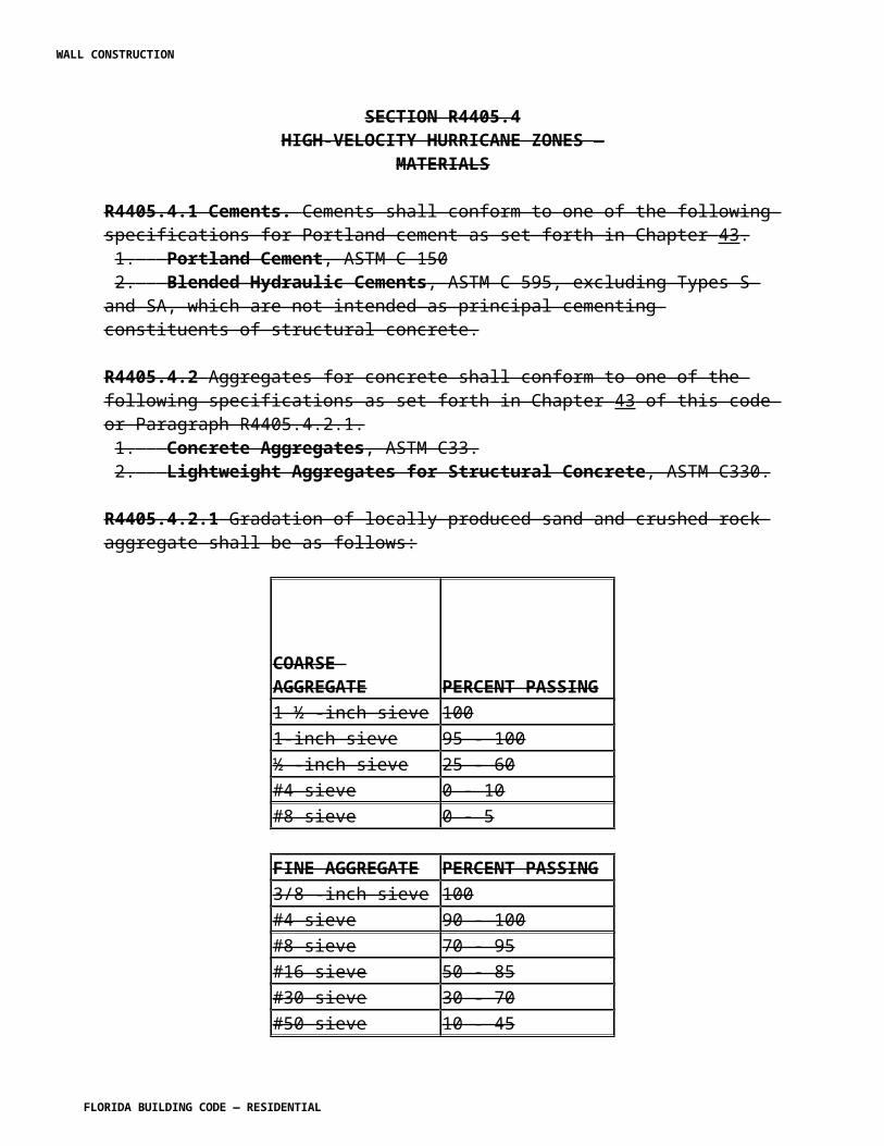
perimeter of each sheet unless the design is based on one or more unsupported edges. Supporting members such as division bars and mullions shall be designed by rational analysis to support the wind pressures set forth in Section R4403. Supporting bars shall be attached at the ends to resist the loads set forth in Section R4403 .
R4410.2.3.3.6 The depth of the glazing rabbet and depth of engagement in the rabbet, for fixed glass, shall be based on consideration of the dimensional reduction from deflection and the dimensional changes caused by temperature.
R4410.2.3.4 Gaskets used in glazing systems shall comply with the following standards as applicable: 1. ASTM C 864, Dense Elastomeric Compression Seal Gaskets, Setting Blocks, and Spacers 2. ASTM C 509, Elastomeric Cellular Preformed Gaskets and Sealing Material 3. ASTM C 1115, Dense Elastomeric Silicone Rubber Gaskets and Accessories 4. ASTM E 2203, Dense Thermoplastic Elastomers Used for Compression Seals, Gaskets, Setting Blocks, Spacers and Accessories.
SECTION R4410.3HIGH-VELOCITY HURRICANE ZONES —
GLASS VENEER
R4410.3.1 Glass veneer shall be as set forth in this section.
R4410.3.2 Dimension. Glass-veneer units shall be not less than 11/32 inch (8.7 mm) in thickness. No unit shall be larger in area than 10 square feet (0.93 m2) where 15 feet (4.6 m) or less above the grade directly below, nor larger than 6 square feet (0.56 m2) where more than 15 feet (4.6 m) above the grade directly below.
R4410.3.3 Attachment. Every glass-veneer unit shall be attached to the backing with approved mastic cement and corrosion-resistant ties and shall be supported on shelf angles.
R4410.3.3.1 Where more than 6 feet (1829 mm) above grade, veneer shall be supported by shelf angles, and ties shall be used in both horizontal and vertical joints.
R4410.3.3.2 Below a point 6 feet (1829 mm) above grade, glass veneer shall rest on shelf angles. Veneering shall not be supported on construction which is not an integral part of the wall, and over sidewalks shall be supported on a shelf angle not less than 1/4 inch (6.4 mm) above grade.
R4410.3.3.3 All edges of glass veneer shall be ground.
WALL CONSTRUCTION
FLORIDA BUILDING CODE — RESIDENTIAL
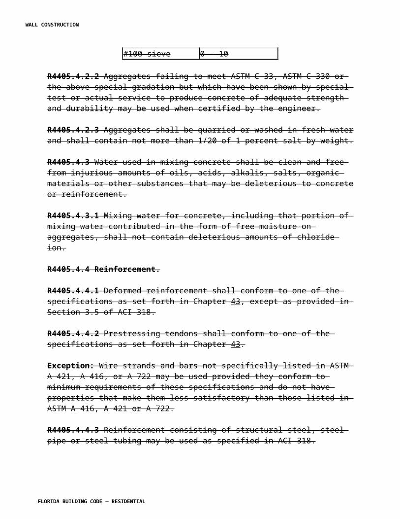
R4410.3.4 Mastic.
R4410.3.4.1 The mastic shall cover not less than one-half of the area of the unit after the unit has been set in place and shall be neither less than 1/4 inch (6.4 mm) nor more than 1/2 inch (12.7 mm) in thickness.
R4410.3.4.2 The mastic shall be insoluble in water and shall not lose its adhesive qualities when dry.
R4410.3.4.3 Absorbent surfaces shall be sealed by a bonding coat before mastic is applied. The bonding coat shall be cohesive with the mastic.
R4410.3.4.4 Glass veneer surfaces to which mastic is applied shall be clean and uncoated.
R4410.3.4.5 Space between edges of glass veneer shall be filled uniformly with an approved type pointing compound.
R4410.3.5 Shelf angles and ties.
R4410.3.5.1 Shelf angles shall be of corrosion-resistant material capable of supporting four times the width of the supported veneer. The shelf angles shall be spaced vertically in alternate horizontal joints, but not more than 3 feet (914 mm) apart. Shelf angles shall be secured to the wall at intervals not exceeding 2 feet (610 mm) with corrosion-resistant bolts not less than 1/4 inch (6.4 mm) diameter. Bolts shall be set in masonry and secured by lead shields.
R4410.3.5.2 Ties shall be of corrosion-resistant metal as manufactured especially for holding glass-veneer sheets to masonry surfaces. There shall be not less than one such approved tie for each 2 square feet (0.19 m2) of veneer surface.
R4410.3.6 Backing. Exterior glass veneer shall be applied only upon masonry, concrete or stucco.
R4410.3.7 Expansion joints. Glass veneer units shall be separated from each other and from adjoining materials by an expansion joint at least 1/16 inch (1.6 mm) in thickness. There shall be at least 1/64 inch (0.4 mm) clearance between bolts and the adjacent glass.
SECTION R4410.4HIGH-VELOCITY HURRICANE ZONES-
STORM SHUTTERS/EXTERNAL PROTECTIVE DEVICES
R4410.4.1 General. Unless exterior wall components including but not limited to structural glazing, doors and windows of enclosed buildings have specific Product Approval to preserve the enclosed building envelope against impact loads as set forth in Section R4403, all such components shall be protected by product approved storm shutters.
WALL CONSTRUCTION
FLORIDA BUILDING CODE — RESIDENTIAL
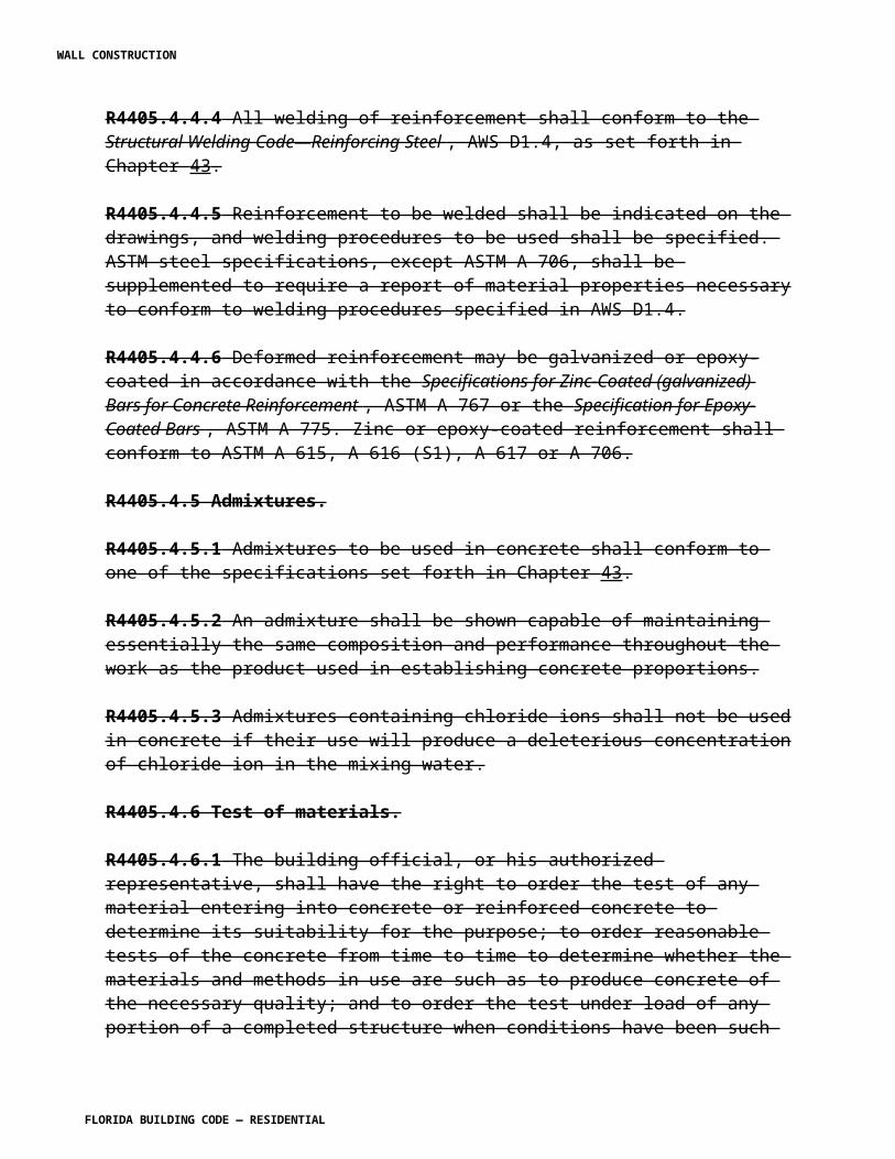
R4410.4.2 The storm shutters shall be designed and constructed to insure a minimum of 1 inch (25 mm) separation at maximum deflection with components and frames of components they are to protect unless the components and frame are specifically designed to receive the load of storm shutters, and shall be designed to resist the wind pressures as set forth in Section R4403 by methods admitting of rational analysis based on established principles of design. Storm shutter shall also be designed to comply with the impact load requirements included within Section R4403.
R4410.4.3 The storm shutter design calculations and detailed drawings, including attachment to the main structure, shall be prepared by and bear the seal of a qualified Florida-registered delegated engineer, or if qualified to prepare such design, by the engineer or architect of record, which architect or engineer shall be proficient in structural design. The architect or engineer of record shall, in all instances, review and approve documents prepared by the delegated engineer.
R4410.4.4 Storm shutters shall be approved by the product control section and shall bear the name of the company engraved in every section of the system.R4410.4.5 Deflection shall not exceed the limits set forth in Section R4403.
R4410.4.6.1 Shutters used to protect openings above the first story of any building or structure must be permanently installed and closable from the inside of the building or structure unless such openings are accessible without the use of a ladder or lift, or shutters can be installed from the interior of the building or structure.
Exception: Group R3 detached single-family residences not exceeding two stories.
R4410.4.7 Storm shutters must completely cover an opening in all directions.
R4410.4.7.1 On any side of an opening, the maximum side clearance between the shutter and a wall or inset surface shall be 1/4 inch (6.4 mm). Any distance in excess of 1/4 inch (6.4 mm) shall require end closure or shutter overlap, where applicable.
R4410.4.7.2 Shutter overlap shall be a minimum of one and one-half times the side clearance between the shutter and wall.
R4410.4.7.3 End closures shall be designed to resist wind loads specified in Section R4403, based on rational analysis.
SECTION R4410.5HIGH-VELOCITY HURRICANE ZONES —
CURTAIN WALLS
R4410.5.1 Scope. This section prescribes requirements for curtain walls of buildings or structures regulated by this code.
WALL CONSTRUCTION
FLORIDA BUILDING CODE — RESIDENTIAL
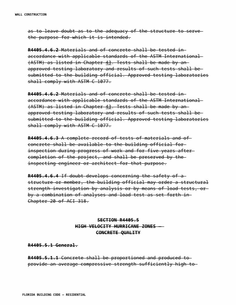
R4410.5.2 Definition. A curtain wall is any prefabricated assembly of various components to enclose a building usually attached to and/or supported by the building frame other than a single door, or window, masonry units, poured in place concrete and siding of single membrane metal, wood or plastic.
R4410.5.3 Curtain walls, as defined in Section R4410.5.2, shall be designed and constructed in accordance with the requirements of this section.
R4410.5.4 Structural glazing in curtain walls shall also comply with the requirements of Section R4410.6.
R4410.5.5 General.
R4410.5.5.1 All structural elements of curtain wall systems and their attachments (including embedments) to the main structural frame shall be designed by and bear the seal of a qualified Florida-registered delegated engineer, or if qualified to prepare such design, by the engineer or architect of record, which architect or engineer shall be proficient in structural design. The engineer of record shall, in all instances, review and approve documents prepared by the delegated engineer.
R4410.5.5.2 Curtain wall systems supported from more than two adjacent floors shall be designed to withstand all imposed loads without exceeding allowable stresses in the event of destruction or failure of any single span within the system. Documents for the main building permit shall include sufficient details describing the curtain wall system attachment to the main structure. This portion of the contract documents, if not prepared by the qualified engineer or architect of record, shall bear the signature and seal of the qualified Florida-registered delegated engineer charged with the responsibility for the design of the curtain wall system.
R4410.5.5.3 Individual mullions acting as a continuous member shall transfer loads through supports from no more than three adjacent floors.
R4410.5.5.4 Materials. The materials used in any curtain wall shall comply with the applicable provisions of this code.
SECTION R4410.6HIGH-VELOCITY HURRICANE ZONES —
STRUCTURAL GLAZING SYSTEMS
R4410.6.1 Scope. This section prescribes requirements for structural glazing systems of buildings or structures regulated by this code.
WALL CONSTRUCTION
FLORIDA BUILDING CODE — RESIDENTIAL
R4410.6.2 Application.
R4410.6.2.1 Structural glazing, as defined in Section R4410.5.3, shall be designed and constructed in accordance with the requirements of this section.
R4410.6.2.2 Structural glazing systems used in curtain walls shall also comply with the requirements of Section R4410.
R4410.6.3 Definition. The terms used in this section shall be defined as set forth in Section Chapter 2 of this code.
R4410.6.4 Standards. Adhesives and sealants used in structural glazing systems shall comply with following standards:
ASTM C 794, Test Method for Adhesion-In-Peel of Elastomeric Joint Sealants.
ASTM C 920, Specification for Elastomeric Joint Sealants.
ASTM D 412, Test Methods for Rubber Properties in Tension.
ASTM D 624, Test Method for Rubber Property-Tear Resistance.
ASTM D 2240, Test Method for Rubber Property- Durometer Hardness.
Federal Specifications TT-S-001543A and TT-S-00230C.
ASTM E 331, Test Method for Water Penetration of Exterior Windows, Curtain Walls and Doors.
ASTM E 330, Test Method for Structural Performance of Exterior Windows, Curtain Walls and Doors.
R4410.6.5 Design.
R4410.6.5.1 General. Structural glazing systems shall be designed by and bear the seal of a Florida-registered professional engineer.
R4410.6.5.2 Materials.
R4410.6.5.2.1 Identification. All materials shall be clearly identified as to manufacturer and manufacturer's product number.
R4410.6.5.2.2 Adhesives and sealants.
R4410.6.5.2.2.1 Only approved silicone elastomer adhesives and sealants shall be used for fastening glass lights and other panels to curtain wall framing.
WALL CONSTRUCTION
FLORIDA BUILDING CODE — RESIDENTIAL
R4410.6.5.2.2.2 Such adhesives and sealants shall be of a polymer that is 100 percent silicone.
R4410.6.5.2.2.3 Adhesives and sealants shall have been tested in accordance with the standards set forth in Section R4410.6.4.
R4410.6.5.3 Manufacturer's testing, recommendation and approval.
R4410.6.5.3.1 Compatibility of all components and fabrication procedures of structural glazing systems shall be tested, approved and recommended in writing by the manufacturer of the adhesive; the manufacturer of the coating; whether it is anodized, baked or otherwise applied and the manufacturer of the glass panel.
R4410.6.5.3.2 Manufacturer's testing, recommendation and approval shall address, but shall not be limited in scope by the following sections.
R4410.6.5.3.2.1 The compatibility of the sealant with metal, glazing materials, shims, spacers, setting blocks, backer rods, gaskets and other materials.
R4410.6.5.3.2.2 Adhesion to the designated substrates and adhesion of the substrates to the base metal.
R4410.6.5.3.2.3 The design and structural capability of silicone joints and cross sections.
R4410.6.5.4 Structural requirements.
R4410.6.5.4.1 Design of structural seals.
R4410.6.5.4.1.1 The design stress of the structural silicone shall not exceed 20 psi (138 kPa) for materials having a minimum strength of 100 psi (690 kPa) at the weakest element in the line of stress.
R4410.6.5.4.1.2 Such design stress shall also provide for a safety factor of not less than 5.0.
R4410.6.5.4.1.3 Safety factors greater than 5.0 shall be specified by the engineer when required or recommended by the manufacturer.
R4410.6.5.4.1.4 The silicone structural seal shall have a maximum modulus of elasticity to allow no more than 25 percent movement of the joint width at 20 psi (138 kPa) stress.
R4410.6.5.4.1.5 In insulating glass units, the secondary silicone seal shall be designed to withstand a minimum of half the design negative wind load applicable to the outboard lights.
R4410.6.5.4.2 Bonding limits. Structural glazing shall be limited to adhesive bonding on one side or on two opposing sides of an infill glass lights or panel.
WALL CONSTRUCTION
FLORIDA BUILDING CODE — RESIDENTIAL

Exception: Three or four side bonding shall be permitted only when structural glazing units are shop fabricated and shop glazed.
R4410.6.5.4.3 Job-site reglazing.
R4410.6.5.4.3.1 Job-site replacement reglazing shall be permitted only when performed following a procedure approved in writing by the applicable structural silicone manufacturer.
R4410.6.5.4.3.2 Replacement shall be performed only by individuals or firms approved or certified by the silicone manufacturer.
R4410.6.6 Inspections, testing and recertification.
R4410.6.6.1 A minimum of 1 percent of the structurally glazed panels shall be tested for load carrying capacity and sealant adhesion in accordance with Section R4403 and ASTM E 330.
R4410.6.6.2 Structural glazed panels shall be inspected by a Florida-registered architect or licensed engineer for conformance with the approved design and installation procedures determined by the authority having jurisdiction prior to the erection of such panels and after the seal curing period established by the silicone manufacturer.
R4410.6.6.3 It shall be the responsibility of the contractor to verify the adhesion of the cured sealant periodically throughout the application to assure compliance with the manufacturer's specifications and quality of application.
R4410.6.6.4 Structural glazing systems on threshold buildings shall be recertified by the owner as specified by the authority having jurisdiction at six-month intervals for the first year after installation. Subsequently, such systems shall be recertified every five years at regular intervals.
R4410.6.6.5 Such recertifications shall determine the structural condition and adhesion capacity of the silicone sealant.
[S5017 AS]
Section R4411. Change to read as follows:
SECTION R4411HIGH-VELOCITY HURRICANE ZONES —
GYPSUM BOARD AND PLASTER
R4411.1 Refer to Chapter 25 of the Florida Building Code, Building .
WALL CONSTRUCTION
FLORIDA BUILDING CODE — RESIDENTIAL
SECTION R4411.3HIGH-VELOCITY HURRICANE ZONES —
STUCCO
R4411.3.2 Stucco on walls other than concrete or masonry.
R4411.3.2.2 Moisture barrier. Wood shall be covered with 15-pound (9 kg) roofing felt, or other approved equally moisture-resisting layer, and metal reinforcement as set forth herein.
R4411.3.2.3 Metal reinforcement.
R4411.3.2.3.1 Stucco shall be reinforced with galvanized expanded metal weighing no less than 1.8 pounds per square yard (0.98 kg/m2), or galvanized welded or woven wire-fabric weighing no less than 1 pound per square yard (0.54 kg/m2).
R4411.3.2.3.2 All metal lathing shall be lapped not less than 1 inch (25 mm).
R4411.3.2.3.3 Metal reinforcement shall be furred out from the backing by an approved method.
R4411.3.2.3.4 Fastenings into wood sheathing or wood framing shall be by galvanized nails, with heads not less than 3/8 inch (9.5 mm) in diameter, driven to full penetration, using a minimum of two nails per square foot (0.093 m2), or by approved staples having equal resistance to withdrawal.
R4411.3.2.3.5 The fastening of rib-lath to metal members shall be by #8 galvanized sheet-metal screws, using a minimum of two screws per square foot (0.093 m2).
R4411.3.2.4 Application.
R4411.3.2.4.1 Stucco applied on metal lath shall be three-coat work applied to a total thickness of not less than 1/2 inch (12.7 mm) thickness except as required to meet fire resistance requirements.
R4411.3.2.4.2 The first coat shall be forced through all openings in the reinforcement to fill all spaces and scored horizontally.
R4411.3.2.4.3 The second coat shall be applied after the first coat has set sufficiently to provide a rigid backing.R4411.3.2.4.4 The third coat shall be applied as soon as the second coat has attained initial set.
SECTION R4411.4HIGH-VELOCITY HURRICANE ZONES —
WALL CONSTRUCTION
FLORIDA BUILDING CODE — RESIDENTIAL
GYPSUM BOARD PRODUCTS AND ACCESSORY ITEMS
R4411.4.2 Standards. The following standards are adopted as set forth in Chapter 43.
Application and finishing of gypsum panel products GA-216-07
Fire Resistance Design Manual GA-600-06.
Specification for Gypsum Wallboard, ASTM C 36.
Specification for General Requirements for Zinc-Coated (Galvanized) Steel Sheets, by the Hot-Dip Process, ASTM A 525.
Specification for Light-gauge Steel Studs, Runners, and Rigid Furring Channels, ASTM C 645.
Specification for Joint Treatment Materials for Gypsum Wallboard Construction, ASTM C 475.
R4411.4.4 Wood studs and wood ceiling supports. Wood studs and wood ceiling supports shall comply with Section R4409.
[S5018 AS]
Section R4412. Change to read as follows:
SECTION R4412HIGH-VELOCITY HURRICANE ZONES —
PLASTICS
R4412.1.1 General Refer to Chapter 26 of the Florida Building Code, Building .
R4412.1.1.1 Plastic materials used as structural elements shall be designed by methods admitting of rational analysis according to established principles of mechanics.
R4412.1.1.4 Plastic structural elements, other than sheets, shall be designed by a Florida-registered professional engineer or a Florida-registered architect.
R4412.1.2 Definitions.
APPROVED FOAM PLASTIC. An approved foam plastic shall be any thermoplastic, thermosetting or reinforced thermosetting plastic material that has a minimum self-ignition temperature of 650°F (343°C) or greater when tested in accordance with ASTM D 1929. It shall have a smoke density rating not greater than 450 and a flame spread of 75 or less when tested in accordance with ASTM E 84.
WALL CONSTRUCTION
FLORIDA BUILDING CODE — RESIDENTIAL

APPROVED PLASTIC. An approved plastic shall be any thermoplastic, thermosetting or reinforced thermosetting plastic material which has a self-ignition temperature of 650°F (343°C), or greater when tested in accordance with ASTM D 1929, a smoke density rating no greater than 450 when tested in the way intended for use by ASTM E 84 or a smoke density rating no greater than 75 when tested in the thickness intended for use according to ASTM D 2843 and which meets one of the following combustibility classifications:
CLASS C-1. Plastic materials that have a burning extent of 1 inch per minute (25.4 mm) or less when tested in nominal 0.060 inch (1.5 mm) thickness or in the thickness intended for use by ASTM D 635.
CLASS C-2. Plastic materials that have a burning rate of 21/2 inches (64 mm) per minute or less when tested in nominal 0.060 inch (1.5 mm) thickness or in the thickness intended for use by ASTM D 635.
Approved plastics for outdoor exposure shall be evaluated for outdoor durability in accordance with the Voluntary Standard Uniform Load Test Procedure for Thermoformed Plastic Domed Skylights , of the AAMA/WDMA 101/IS2/NAFS, Voluntary Performance Specification for Windows, Skylights and Glass Doors, as follows: 1. Outdoor exposure conditions: Specimen exposed in Florida at 45 degree south exposure for a period of five years. 2. Alternate: a. Exposure to xenon arc weatherometer using a 6500-watt lamp per ASTM G 26-77 and ASTM D 2565 for a period of 4,500 hours. b. Impact testing, after exposure test as above, per ASTM D 256.
FINISH RATING. The time, as determined in accordance with ASTM E 119, at which a thermal barrier reaches a temperature rise of 240°F (116°C), above ambient or an individual temperature rise of 324°F (162°C), above ambient as measured on the plane of the thermal barrier nearest to foam plastic.
FLAME SPREAD RATING. The measurement of flame spread on the surface of materials or their assemblies as determined in accordance with ASTM E 84.
GLASS FIBER REINFORCED PLASTIC. Plastic reinforced with glass fibers having not less than 20 percent of glass fibers by weight.
LIGHT DIFFUSING SYSTEM. A suspended construction consisting in whole or in part of lenses, panels, grids or baffles suspended below independently mounted electrical lighting sources.
PLASTIC GLAZING. Plastic materials that are glazed or set in frame or sash and not held by mechanical fasteners which pass through the glazing material.
PLASTIC ROOF PANELS. Plastic materials that are fastened to structural panels or sheathing and which are used as light transmitting media in the plane of the roof.
WALL CONSTRUCTION
FLORIDA BUILDING CODE — RESIDENTIAL
PLASTIC SANDWICH PANELS. Panels of foam plastic sandwiched between incombustible skins.
PLASTIC WALL PANELS. Plastic materials that are fastened to structural panels or sheathing and which are used as light transmitting medium in exterior walls.
SKYLIGHT. An assembly that includes plastic materials used as light transmitting medium and which is located above the plane of the roof
SMOKE DENSITY. A numerical value of smoke development, determined by measuring the area under the curve of light absorption versus time, in accordance with ASTM E 84 or ASTM D 2843.
THERMOPLASTIC MATERIALS. A plastic material that is capable of being repeatedly softened by increase of temperature and hardened by decrease of temperature.
THERMOSETTING MATERIALS. A plastic material that is capable of being changed into a substantially non-reformable product when cured.
[F5019 AS]
CHAPTER 45. Change Chapter 44, Referenced Standards, to Chapter 45 as follows:
CHAPTER 45 44, REFERENCED STANDARDS[CA5460 AS]
Add or update the following standards:
WALL CONSTRUCTION
FLORIDA BUILDING CODE — RESIDENTIAL
AAF Aluminum Association of Florida, Inc. 3165 McCrory Place, Suite 185 Orlando, FL 32803
Standard Referenced in codereference number Title section number
AAF-10 Guide to Aluminum Construction in High Wind Areas 2010 R301.2.1.1.1 [S5840 AS]
AAMA American Architectural Manufacturers Association 1827 Walden Office Square, Suite 550 Schaumburg, IL 60173
Standard Referenced in codereference number Title section number
AAMA/WDMA/CSA 101/I.S.2/A440—11
North American Fenestration Standards/Specifications for Windows, Doors and Skylights R308.6.9, R612.3,
N1102.4.3
506—06 or 08 or 11(S5664 AM R1
Voluntary Specifications for Hurricane Impact and Cycle Testing of Fenestration Products
R301.2.1.2
AAMA/NPEA/NSA2100-11[S5895 AS](S5659 AM)
Voluntary Specifications for Sunrooms R301.1.1, R301.2.1.1.2
FMA/AAMA 100-12 Standard Practice for the Installation of Windows with Flanges or Mounting R703.8 FMA/AAMA 200-12 09 Standard Practice for the Installation of Windows with Frontal Flanges
for Surface Barrier Masonry R703.8 FMA/WDMA 250-10 Standard Practice for the Installation of Non-Frontal Flange Windows with R703.8
Mounting Flanges for Surface Barrier Masonry for Extreme Wind/Water ConditionsFMA/AAMA/WDMA300-12 Standard Practice for the Installation of Exterior Doors in Wood Frame
Construction for Extreme Wind/Water Exposure R703.8 [S5891 AM R1]
AFPA American Forest and Paper Association (American Wood Council Division) 111 19th Street, NW, #800
WALL CONSTRUCTION
FLORIDA BUILDING CODE — RESIDENTIAL
Washington, DC 20036
Standard Referenced in codereference number Title section number
NDS—12 National Design Specification (NDS) for Wood Construction with R404.2.2, R502.2, 2005 Supplement Table R503.1, R602.2, R802.2, AFPA—2012 Span Tables for Joists and Rafters R502.2.2, R802.2.2, R802.2.3 PWF—2007 Permanent Wood Foundation (PWF) Design Specification R401.1WFCM—2012 Wood Frame Construction Manual for One- and Two-family Dwellings R301.2.1.1, R614.2.5 , R614.3.1 , R802.2
APSPAssociation of Pool and Spa Professionals2111 Eisenhower AvenueAlexandria, VA 22314
Standard Referenced in codereference number Title section number
ANSI/APSP 7—06 American National Standard for Suction Entrapment Avoidance in Swimming Pools, Wading Pools, Spas, Hot Tubs, and Catch AG106.1
Basins…………….…………………… .R4201.6.1, R4201.6.3, R4201.6.6
ANSI/NSPI 3—99 American National Standard for Permanently Installed Residential AG104.1Spas…………………………………………………………… R4201.6.1
ANSI/NSPI 4—99 American National Standard for Aboveground/On ground AG103.2 Residential Swimming Pools . . . . . . . . . . . . . . . . . .. . . . . . . R4201.6.1
. ANSI/ NSPI 5-2003 American National Standard for Residential In ground Swimming AG103.1
Pools……………………………………………………………. R4201.6.1
ANSI/NSPI 6—99 American National Standard for Portable Spas. . . . . . .. . . . . . AG104.2, R4201.6.1
(SW5444 AS)
ASCE American Society of Civil Engineers 1801 Alexander Bell Drive Reston, VA 20191-4400Standard Referenced in codereference number Title section number 5— 08 Building Code Requirements for Masonry Structures R301.2.1.1, R318.4, R606.1, R606.1.1, R606.2.4 7— 10 Minimum Design Loads for Buildings and Other Structures R301.2.1.1, R301.2.1.2.1.1, R301.2.1.6,
Table R611.3(1), Table R611.7.4, R612.2, R612.4, R615.1, Table R907.8.1
ASTM ASTM International 100 Barr Harbor Drive
WALL CONSTRUCTION
FLORIDA BUILDING CODE — RESIDENTIAL
West Conshohocken, PA 19428Standard Referenced in codereference number Title section number A 82/A 82M -05a Specification for Steel Wire, Plain for Concrete Reinforcement
R606. 9.10 , Table R606.9.10.1 A 525 - 87 Specification for Steel Sheet Zinc coated (Galvanized) Steel Wire Table R606.9.10.1
A 653/A 653M-08 Specification for Steel Sheet, Zinc Coated (Galvanized) or Zinc Iron R505.2.1, R505.2.3, Alloy Coated (Galvanized) by the Hot Dip Process
Table 905.4.4, B 370—09 Specification for Copper Sheet and Strip for Building Construction Table R905.4.4 , R703.8
C 90—11b08 Specification for Load Bearing Concrete Masonry Units Table R301.2(1), R606.4, R4407.2.7.2 [S6019AS] C 94/C 94M -09 Specification for Ready Mixed Concrete R404.1.2.3.2, R611.5.1.1, C 920 - 08 Specification for Elastomeric Joint Sealants ………………….. . R613.8.1 , R703.8 C 926-11a06 Specification for Application of Portland Cement Based Plaster R202, R703.6.2.1, [S6019AS] C 1063-12a08 Specification for Installation of Lathing and Furring to Receive Interior and Exterior Portland Cement-based Plaster [No change][S6019AS]C 1281- 03 Standard Specification for Preformed Tape Sealants for Glazing Applications .…R613.8.1.8.1 , R703.8 D 226- 06 Specification for Asphalt saturated (Organic Felt) Used in Roofing and Waterproofing R905.2.2 , R905.2.3, R905.2.7 , R905.4.3, R905.5.3, R905.5.3.3, R905.6.3.3,
R905.7.3, Table R905.7.5, R905.8.3, R905.8.3.3, R905.8.3.4, R905.8.10.1, Table R905.9.2, R905.10.5, R905.10.5.2, R907.7.2
D 5034—95 Test Method for Breaking Strength and Elongation of Textile Fabrics (Grab Test) Specifications for Adhesives for Field Gluing Plywood to Lumber Framing for Floor Systems R4201.17.1.15ASTM D 6509-00 Specification for Atactic Polypropylene (APP) Modified Bituminous
Base Sheet Materials Using Glass Fiber Reinforcements ………… ……….Table R905.11.2D6757- 07 Standard Specification for Underlayment Felt Containing Inorganic Fibers
Used in Steep-Slope Roofing R905.2.3, R905.2.7, R905.4.3, R905.4.3.3, R905.5.3, R9055.3.3, R905.6.3, R905.6.3.3, R905.10.5, R905.10.5.2
D7158- 07 Standard Test Method for Wind Resistance of Sealed Asphalt Shingles (Uplift Force/Uplift Resistance Method) R905.2.6.1, Table R905.2.6.1E 96 / E96M-05 Test Method for Water Vapor Transmission of Materials M1411.5 E 1300—04e01, Practice for Determining Load Resistance of Glass in Buildings [NOT REFERENCED FROM CODE] 07e01 or 09a98 [S5664 AM]
E 1886-02 or 05 Test Method for Performance of Exterior Windows, Curtain Walls, Doors and R301.2.1.2, R301.2.1.2.1.1
Storm Shutters Impacted by Missiles and Exposed to Cyclic Pressure Differentials R612.3.1,R612.6.1 .[S5664 AM]
E1996-02, 05 Standard Specification for Performance of Exterior Windows, Curtain Walls, Doors R301.2.1.2,06, 09, or 12 and Impact Protective Systems Impacted by Windborne Debris in Hurricanes R612.6.1 [S5664 AM]F 1346-91(2003) Performance Specification for Safety Covers and Labeling Requirements for
All Covers for Swimming Pools , Spas and Hot Tubs R4201.2, R4201.17
Florida Codes
WALL CONSTRUCTION
FLORIDA BUILDING CODE — RESIDENTIAL
Florida Building Commission Building Codes and StandardsDepartment of Community Affairs Business and Professional Regulation2555 Shumard Oak Blvd. 1940 N. Monroe St.Tallahassee, Fl. 32399-2100 0772
FRSA Florida Roofing, Sheet Metal and Air Conditioning Contractors Association4111 Metric DriveWinter Park, Florida 32792
Standard Referenced in codereference number Title section numberFRSA/TRI April 2012 Florida High Wind Concrete and Clay Roof R905.3, R905.3.2, R905.3.3, R905.3.3.1,(04-12)07320/8—05 Tile Installation Manual, Fourth Fifth Edition R905.3.6, R905.3.7, R905.3.7.1, R905.3.8 [S5604 AS]
MAF Masonry Association of Florida398 Camino Gardens Blvd, Suite 108Boca Raton, FL 33432
Standard Referenced in codereference number Title section number MAF-97 Guide to Concrete Masonry Residential Construction in High Wind Areas R301.2.1.1 [S6018 AS]
Appendix E: Manufactured housing used as dwellings. Change to read as follows:
Appendix E: Chapter 9B-53, Standard for Mitigation of Radon in Existing Buildings.
See Appendix E of the 2010 FBCR
Appendix F: Radon control methods. Change to read as follows:
Appendix F: Chapter 9B-52, Florida Standard for Passive Radon-Resistant New Residential Building Construction.
See Appendix F of the 2010 FBCR.See Appendix F
Appendix G Swimming Pools, Spas and Hot Tubs. Change to read as shown.
WALL CONSTRUCTION
FLORIDA BUILDING CODE — RESIDENTIAL
APPENDIX GSWIMMING POOLS, SPAS AND HOT TUBS
RESERVED.
WALL CONSTRUCTION
FLORIDA BUILDING CODE — RESIDENTIAL