Bubbles Formation at an Orifice in an Inviscid Liquid.pdf
11
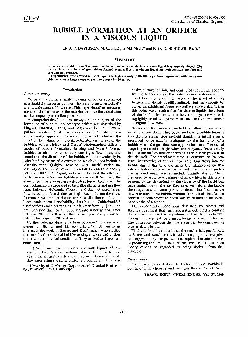
IChem E 0263-8762/97/$10.00+0.00 © Institution of Chemical Engineers BUBBLE FORMATION AT AN ORIFICE IN A VISCOUS LIQUID By J. F. DAVIDSON, M.A., Ph.D., A.M.I.Mech.* and B. O. G. SCHULER, Ph.D.* SUMMARY A theory of bubble formation based on the motion of a bubble in a viscous liquid has been developed. The theory gives the volume of gas bubbles formed at an orifice in a viscous liquid for both constant gas flow and constant gas pressure. Experiments were carried out with liquids of high viscosity (500-1040 cp). Good agreement with theory was obtained over a large range of gas flow rates (0-50 mIls). Introduction Literature survey When air is blown steadily through an orifice submerged in a liquid it emerges as bubbles which are formed periodically over a wide range of flow rates. This paper describes measure- ments of the frequency of the bubbles and also the calculation of the frequency from first principles. A comprehensive literature survey on the subject of the formation of bubbles at submerged orifices was described by Hughes, Handlos, Evans, and Maycock l in 1953. Several publications dealing with various aspects of the problem have subsequently appeared. Davidson and Amick 2 studied the effect of the volume of the orifice-chamber on the size of the bubbles, whilst Helsby and Tuson 3 photographed different modes of bubble formation. Benzing and Myers 4 formed bubbles of air in water at very small gas flow rates, and found that the diameter of the bubble could conveniently be calculated by means of a correlation which did not include a viscosity term. Quigley, Johnson, and Harris 5 varied the viscosity of the liquid between 1 and 400 cp and the density between 1·00 and 1'57 g/ml, and concluded that the effect of both these variables on bubble-size was small. Similarly the effect of surface tension was negligible at higher flow rates. The controlling factors appeared to be orifice diameter and gas flow rate. Leibson, Holcomb, Cacoso, and Jacmic 6 used larger flow rates and found that at high Reynolds numbers the formation was not periodic: the size distribution fitted a logarithmic normal probability distribution. Calderbank 7 ,b used orifices and slots ranging in diameter from -r.-t in., and has suggested that for air bubbling into water at flow rates between 20 and 250 ml/s, the frequency is nearly constant within the range 15-20 bubbles/so Further relevant data have been published in a series of papers by Siemes and his co-workers. 9 - 14 Of particular interest is the work of Siemes and Kaufmann,ll who studied the periodic formation of bubbles at single submerged orifices under various physical conditions. They arrived at important conclusions: (i) With small gas flow rates and with liquids of low viscosity the difference in volume between the bubble formed at any particular flow rate and that formed at infinitely small flow rates using the same orifice is independent of the vis- * University of Cambridge, Department of Chemical Engineer- ng , Pembroke Street, Cambridge. cosity, surface tension, and density of the liquid. The con- trolling factors are gas flow rate and orifice diameter. (ii) For liquids of high viscosity the effect of surface tension and density is still negligible, but the viscosity be- comes an additional factor controlling bubble size. It is at this point worth noting that for viscous liquids the volwne of the bubble formed at infinitely small gas flow rates is negligibly small compared with the total volume formed at higher flow rates. Siemes and Kaufmann suggested the following mechanism of bubble formation. They postulated that a bubble forms in two distinct stages. For inviscid liquids the initial stage is presumed to be exactly analogous to the formation of a bubble when the gas flow rate approaches zero. The second stage is presumed to begin when the buoyancy forces exactly balance the surface tension forces and the bubble proceeds to detach itself. The detachment time is presumed to be con- stant, irrespective of the gas flow rate. Gas flows into the bubble during this time and hence the influence of gas flow rate on bubble volume can be derived. For viscous liquids a similar mechanism was suggested. Initially the bubble is supposed to grow to a definite volume, which in this case is to some extent dependent on the viscosity of the liquid but, once again, not on the gas flow rate. As before, the bubble then requires a constant period to detach itself, so that the flow rate affects the bubble volume. The actual time for the process of detachment to occur was calculated to be several hundredths of a second. The experimental conditions described by Siemes and Kaufmann suggest that their apparatus delivered a constant flow of gas, not as in the case where gas flows from a chamber at constant pressure through an orifice into the forming bubble. The difference between the two cases will be considered in greater detail below. Finally it should be noted that the mechanism put forward by Siemes and Kaufmann is based entirely upon a description of a suggested physical process. The explanation offers no way of predicting the time of detachment, and for this reason the theory cannot be regarded as being derived from first principles. Present work The present paper deals with the formation of bubbles in liquids of high viscosity and with gas flow rates between 0 TRANS.INSTN CHEM. ENGRS, Vol. 38, 1960 SlO5
-
Upload
linarubio4 -
Category
Documents
-
view
155 -
download
2
Transcript of Bubbles Formation at an Orifice in an Inviscid Liquid.pdf
IChemE 0263-8762/97/$10.00+0.00© Institution of Chemical Engineers
BUBBLE FORMATION AT AN ORIFICEIN A VISCOUS LIQUID
By J. F. DAVIDSON, M.A., Ph.D., A.M.I.Mech.* and B. O. G. SCHULER, Ph.D.*
SUMMARYA theory of bubble formation based on the motion of a bubble in a viscous liquid has been developed. Thetheory gives the volume of gas bubbles formed at an orifice in a viscous liquid for both constant gas flow andconstant gas pressure.
Experiments were carried out with liquids of high viscosity (500-1040 cp). Good agreement with theory wasobtained over a large range of gas flow rates (0-50 mIls).
IntroductionLiterature survey
When air is blown steadily through an orifice submergedin a liquid it emerges as bubbles which are formed periodicallyover a wide range of flow rates. This paper describes measurements of the frequency of the bubbles and also the calculationof the frequency from first principles.
A comprehensive literature survey on the subject of theformation of bubbles at submerged orifices was described byHughes, Handlos, Evans, and Maycockl in 1953. Severalpublications dealing with various aspects of the problem havesubsequently appeared. Davidson and Amick2 studied theeffect of the volume of the orifice-chamber on the size of thebubbles, whilst Helsby and Tuson3 photographed differentmodes of bubble formation. Benzing and Myers4 formedbubbles of air in water at very small gas flow rates, andfound that the diameter of the bubble could conveniently becalculated by means of a correlation which did not include aviscosity term. Quigley, Johnson, and Harris5 varied theviscosity of the liquid between 1 and 400 cp and the densitybetween 1·00 and 1'57 g/ml, and concluded that the effect ofboth these variables on bubble-size was small. Similarly theeffect of surface tension was negligible at higher flow rates. Thecontrolling factors appeared to be orifice diameter and gas flowrate. Leibson, Holcomb, Cacoso, and Jacmic6 used largerflow rates and found that at high Reynolds numbers theformation was not periodic: the size distribution fitted alogarithmic normal probability distribution. Calderbank7 , b
used orifices and slots ranging in diameter from -r.-t in., andhas suggested that for air bubbling into water at flow ratesbetween 20 and 250 ml/s, the frequency is nearly constantwithin the range 15-20 bubbles/so
Further relevant data have been published in a series ofpapers by Siemes and his co-workers. 9- 14 Of particularinterest is the work of Siemes and Kaufmann,ll who studiedthe periodic formation of bubbles at single submerged orificesunder various physical conditions. They arrived at importantconclusions:
(i) With small gas flow rates and with liquids of lowviscosity the difference in volume between the bubble formedat any particular flow rate and that formed at infinitely smallflow rates using the same orifice is independent of the vis-* University of Cambridge, Department of Chemical Engineer-
ng , Pembroke Street, Cambridge.
cosity, surface tension, and density of the liquid. The controlling factors are gas flow rate and orifice diameter.
(ii) For liquids of high viscosity the effect of surfacetension and density is still negligible, but the viscosity becomes an additional factor controlling bubble size. It is atthis point worth noting that for viscous liquids the volwneof the bubble formed at infinitely small gas flow rates isnegligibly small compared with the total volume formedat higher flow rates.Siemes and Kaufmann suggested the following mechanism
of bubble formation. They postulated that a bubble forms intwo distinct stages. For inviscid liquids the initial stage ispresumed to be exactly analogous to the formation of abubble when the gas flow rate approaches zero. The secondstage is presumed to begin when the buoyancy forces exactlybalance the surface tension forces and the bubble proceeds todetach itself. The detachment time is presumed to be constant, irrespective of the gas flow rate. Gas flows into thebubble during this time and hence the influence of gas flowrate on bubble volume can be derived. For viscous liquids asimilar mechanism was suggested. Initially the bubble issupposed to grow to a definite volume, which in this case isto some extent dependent on the viscosity of the liquid but,once again, not on the gas flow rate. As before, the bubblethen requires a constant period to detach itself, so that theflow rate affects the bubble volume. The actual time for theprocess of detachment to occur was calculated to be severalhundredths of a second.
The experimental conditions described by Siemes andKaufmann suggest that their apparatus delivered a constantflow of gas, not as in the case where gas flows from a chamberat constant pressure through an orifice into the forming bubble.The difference between the two cases will be considered ingreater detail below.
Finally it should be noted that the mechanism put forwardby Siemes and Kaufmann is based entirely upon a descriptionof a suggested physical process. The explanation offers no wayof predicting the time of detachment, and for this reason thetheory cannot be regarded as being derived from firstprinciples.
Present workThe present paper deals with the formation of bubbles in
liquids of high viscosity and with gas flow rates between 0
TRANS.INSTN CHEM. ENGRS, Vol. 38, 1960
SlO5

S106 JUBILEE SUPPLEMENT-Trans IChemE, Vol 75, December 1997
DAVIDSON AND SCHULER. BUBBLE FORMATION AT AN ORIFICE IN A VISCOUS LIQUID
Fig. I.-Schematic diagram af the apparatus used far the farmation ofbubbles
Capillary
N
F
o EL
A
spex cylinder. Gas temperatures were measured at Nand O.These were always within 0'2°C of the temperature of theliquid in which the bubbles were forming. The temperatureof the liquid itself did not vary by more than 0'1 °C during arun. The frequency of bubble formation was determined bystroboscopic illumination and the pressure in J was givenapproximately by the water manometer, G. More accuratepressure determinations were made by means of a tiltingmanometer connected to the drum J. A Ferranti viscometerwas used to determine the viscosity of the liquid, and thesurface tension was measured by the drop weight method.The liquids used in most of the experiments were aqueoussolutions of glycerol for which density values were obtainedfrom the International Critical Tables. In the few cases whereviscous hydrocarbon oils were used, the densities were determined with the aid of a pyknometer. Provided the orifice wasimmersed in liquid to a depth of more than a few bubblediameters, this depth had no effect upon bubble frequencybut merely altered the pressure necessary to generate thebubbles.
and 50 mIls. Two distinct situations are considered, namely:-(i) In the simplest case there is a constant flow of gas
throughout bubble formation. as when the gas is being fed -+
through a long thin capillary. The surface of the bubble, asit grows, is assumed to be spherical, so that the radius ofthe bubble at any instant of time, t, is known. As the bubblegrows it tends to move upwards, the force being due tobuoyancy. This force has to overcome two resistances,namely, viscous drag of the Stokes kind, and liquid inertiadue to the fact that as the bubble accelerates upwardsome of the liquid also accelerates. The balance betweenthe upward force and the two resistances leads to a differential equation governing the motion, and the solution givesthe distance of the centre of the bubble above the orificeat any time t. Initially, when the bubble is small, its centreis at the orifice. The formation is complete when the bottomof the bubble reaches the orifice, and at this instant thebubble detaches and the process then repeats itself.
(ii) In the second case the bubbles are formed above ahole in a horizontal plate, with liquid above to a finitedepth and gas below at a constant pressure. In this case, whichis of greater practical importance, the gas flow through theorifice varies during bubble formation. This has the effectofmaking more complex the equations governing the motionof the bubble. The basis on which the equations are formulated is, however, similar to that described in paragraph (i)above.The theory bears out several of the findings of Siemes and
Kaufmann. For a constant flow system the bubble size depends upon flow rate and viscosity, whilst surface tension hasno effect. However, with regard to the effects of liquid densityand orifice diameter, the theoretical results are in conflict withthe conclusions of Siemes and Kaufmann. The liquid densityis shown to affect the size of the bubble whilst the influenceof the orifice dimensions is negligible. The orifice diameterbecomes important only when the effective area is small andthe gas flow rate relatively large. Under these conditions thegas receives a considerable amount of momentum whichaffects the motion of the bubble and hence its final volume.
For a constant pressure system, both the surface tension ofthe liquid and the orifice discharge coefficient have to beincluded in the equations governing the motion of the bubble.
The predicted values of bubble volume for both constantflow and constant pressure systems were found to be in goodagreement with results obtained experimentally.
Experimental MethodsA schematic diagram of the apparatus is shown in Fig. 1.
Gas from either a compressor or a cylinder was passed into a25 litre vessel, A, which acted as a buffer. The pressure in Awas indicated by the manometer C and could be maintainedat any desired value by manipulating valve B. In most casesthe pressure was kept at about 1'5 atmospheres absolute.Next the gas passed through an Edwards throttle valve, D,by means of which the flow rate could be controlled. Thethreeway tap, E, enabled the gas to pass either directly to thedrying tube, H, and the rotameter, I, or first through a soapbubble meter, F. J was a 45 litre drum from which the gaspassed through the orifice, K, into the liquid contained in aPerspex cylinder of 14'7 cm diameter. The latter was attacheddirectly to the drum and was surrounded by a thermostat.Land M were helical coils immersed in the same liquid aswas circulated through the thermostat surrounding the Per-
TRANS. INSTN CHEM. ENGRS, Vol. 38, 1960
Sintcred brassplate
(c)
Cb)(a) = constant pressure systems(b) = constant flow systems (large flow rates)(c) = constant flow systems (small flow rates)
Fig. 2.---Dri(ices used
The shapes of the orifices used in the experiments are shownin Figs 2A, 2B, and 2e.
Fig. 2A represents the type of orifice used in the constantpressure systems. The nozzle was made of brass and had a

JUBILEE SUPPLEMENT-Trans IChemE, Vol 75, December 1997
DAVIDSON AND SCHULER. BUBBLE FORMATION AT AN ORIFICE IN A VISCOUS LIQUID
S107
Perspex ring fitted as shown. The purpose of the ring was toeliminate as far as possible the effects of the circulation ofthe liquid (see Appendix). In these experiments the pressuredrop across the orifice was of the order of a few centimetresof water.
For the experiments in which a constant flow throughoutbubble formation is required, it is necessary to have a largepressure drop across the orifice, which can be achieved simplyby making the diameter of the orifice very small. This, however, has the disadvantage that the neck of the bubble is shortat detachment and the bubble subsequently is in such a position that for certain critical flow rates the next bubble, whichrapidly expands in the initial stages, coalesces with it. Thelarger the orifice diameter, the greater the gas flow rate atwhich coalescence first occurs. For large flow rates, a smallorifice has the additional disadvantage of imparting a largemomentum to the gas, which, although it can be approximately accounted for, complicates the theoretical calculations.On the other hand the theoretical boundary conditions aremore closely obeyed if the neck of the bubble is short. Bearingthese considerations in mind three types of orifice wereeventually used:
(i) For very small flow rates (0-2 mils) the orifices wereessentially the same as those used in the constant pressureexperiments, except that the orifice diameters were smalland hence the pressure drops large. Pressure fluctuationswithin the bubbles due to changes in radius of curvaturehad a negligible effect on the flow, especially as the latterdepends on the square root of the pressure difference.
(ii) Experiments were also performed in which the drumJ was by-passed and the gas fed directly into the liquidthrough a length of capillary. A ring, as shown in Fig. 2c,was attached to the end of the capillary and provided thediameter of the capillary was small, the results were thesame as those obtained when the small diameter orifices,described above, were used.
(iii) For larger constant flow rates the orifices used wereof the type shown in Fig. 2B. A piece of sintered brass waswelded to the lower side of the orifice which in otherrespects was similar to that shown in Fig. 2A. The diametersof the orifices were of the same order as those used in theconstant pressure experiments. A high pressure drop couldbe maintained across the sintered brass, resulting in aconstant flow of gas into the bubble. The volume of thecylindrical cavity between the sintered brass and the upperplane of the nozzle was small compared with the volume ofthe final bubble and its effect was neglected. The purposeof the relatively large orifice diameter was two-fold. Firstlythe bubble during detachment had a slightly longer neck.This meant that when the bubble detached, it was far enoughaway from the orifice to avoid contact with the next bubble.In this way the condition assumed in the theory, namelythe periodic formation of single bubbles, was satisfied.Secondly the large cross-sectional area of the orifice keptthe momentum of the gas low.
To help elucidate the mechanism of the formation of abubble it was decided to take cine photographs showing theentire formation. The design of the vessel in which the bubbleswere being formed was slightly modified in order to eliminatedistortion of the picture due to the curvature of the Perspexcylinder, and the stroboscope frequency adjusted until onebubble appeared to be forming every 15 to 20 seconds. Aphotograph of the bubble was then taken every 0·75 s using
an externally triggered 16 mm "Pathe" camera. "Kodak PlusX" proved to be a convenient film for an exposure of 0·2 s.The frequency of the stroboscopic illumination was usuallybetween 9 and 21 flashes/s, so that during each exposure between 1 and 5 pictures were superimposed upon each other.The light output of the Dawe Strobotorch used was approximately constant, irrespective of the frequency, so that nochange of film was necessary when changing from one frequency to another.
Discussion and Results
The following theory attempts to describe the way in whichgas bubbles are formed at an orifice in a liquid. It is assumedthat the gas is supplied at a point source within the liquid andthat the bubbles, as they form, are spherical. Each bubble isassumed to begin with its centre at the point source and theupward motion is determined by a balance between the upward force due to buoyancy and the drag forces due to viscosity and inertia. Now initially the upward velocity of thecentre is small since it starts from rest, and because thebubble is expanding the underside has a downward velocityand the bubble therefore continues to envelop the source ofgas. Subsequently, when the bubble is larger, its base is broughtto rest when the outward velocity of the bubble surface relative to its centre is equal to the upward velocity of the centredue to buoyancy. Thereafter the base has a net upwardvelocity and detachment takes place when it reaches thesource of the gas. The idealised sequence of events is indicated in Fig. 3, and this picture of formation and detachment
(0) (b) (C)
(a) = underside of bubble moving down(b) = bottom point of bubble at rest in lowest position(c) = bottom point of bubble reaches gas source
Fig. 3.-ldea/ised sequence of events during bubble formation in a liquid.Gas supplied from a point source P
was the basis of all the theoretical calculations, although insome cases it was assumed that detachment was delayed untilthe base of the bubble was somewhat above the source of gas.
The theory given below is in two sections. The first sectiondeals with the formation of bubbles at a constant gas flow rateand the second with the case where gas flows through anorifice from a vessel at constant pressure. Each section issubdivided to distinguish between small and large flow rates.The assumptions made and the relevant results obtainedboth by calculation and experiment are given in each case.Obviously the exact conditions assumed by the theory cannotbe realised experimentally, especially if the bubbles are formedjust above horizontal plates. Photographs (Fig. 4) show thatthe bubbles are pear shaped initially, this being due to thefact that the base of the bubble cannot move downwards.Also, some of the boundary conditions, to be discussed in
TRANS. INSTN CHEM. ENGRS, Vol. 38, 1960

SlO8 JUBILEE SUPPLEMENT-Trans IChemE, Vol 75, December 1997
DAVIDSON AND scHikER. BUBBLE FORMATION AT AN ORIFICE IN A VISCOUS LIQUID
Gas flow rate = 24 milsViscosity = 711 cpDensity = 1·25 gjmlRadius of orifice = 0·096 cmBubble volume = 2·5 ml
Fig. 4.-Cine photographs of bubble formation in a viscous liquid
Also, if G is the gas flow rate, then, V, the bubble volumeis given by
detail below, are not exactly obeyed. Nevertheless, the predicted values are in good agreement with the experimentalresults. 4nr3Gt = v= --3 (2)
(3)
(5)
(4)2.g.. (3G) 2/3s = - t5/3•15'1' 4n
Hence_2g (3Gt) 2/3 _ dsv-- - --
9'1' 4n dt
where s is the distance between the centre of the bubble andthe point of gas supply. Integrating equation (3) we have
The bubble will detach when s = r, and hence at detachment,eliminating t from equations (2) and (4),
V = e;r4c;~Gr4.Equation (5) gives the volume of the bubble in terms of the
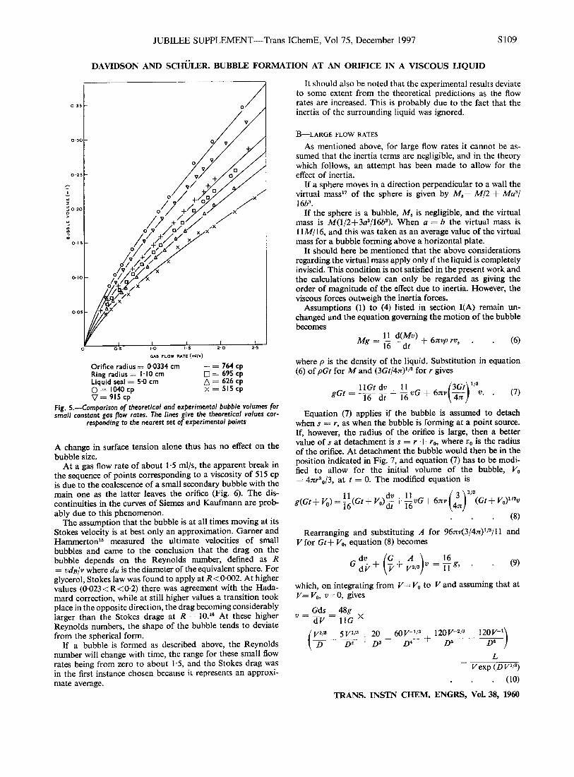
properties of the liquid and the gas flow rate. A comparisonof theoretical and experimental results for aqueous solutionsof glycerol is presented in Fig. 5. Runs were also done forsimilar flow rates using viscous hydrocarbon oils of varyingsurface tension. In each case equation (5) was closely obeyed.
(1)
I-Bubble formation at constant flow rates
A-SMALL FLOW RATES
The theory is based on the following assumptions:1. The bubble is spherical throughout formation.2. Circulation of the liquid is negligible, so that the liquid
surrounding the orifice is at rest when the bubble starts toform (see Appendix).
3. The motion of the bubble is not affected by the presence of another bubble immediately above it.
4. The momentum of the gas is negligible (see Appendix).5. The bubble is at all instants moving at the Stokes
velocity appropriate to its size.Consider the motion of a bubble forming at a point source
in an infinite liquid under the above conditions. In view ofassumption (5), the velocity of the centre of the bubble, v, attime t after the start will be given by the equation:*
* Symbols have the meanings given to them on p. 162
TRANS. INSTN CHEM. ENGRS, Vol. 38, 1960
JUBILEE SUPPLEMENT-Trans IChernE, Vol 75, December 1997 SI09
DAVIDSON AND SCHULER. BUBBLE FORMATION AT AN ORIFICE IN A VISCOUS LIQUID
(6)
(9)
It should also be noted that the experimental results deviateto some extent from the theoretical predictions as the flowrates are increased. This is probably due to the fact that theinertia of the surrounding liquid was ignored.
B-LARGE FLOW RATES
As mentioned above, for large flow rates it cannot be assumed that the inertia terms are negligible, and in the theorywhich follows, an attempt has been made to allow for theeffect of inertia.
If a sphere moves in a direction perpendicular to a wall thevirtual mass l
? of the sphere is given by M.+ M/2 + Ma"/16b3 •
If the sphere is a bubble, M. is negligible, and the virtualmass is M(l/2+3a3/16b3). When a = b the virtual mass is11M/I 6, and this was taken as an average value ofthe virtualmass for a bubble forming above a horizontal plate.
It should here be mentioned that the above considerationsregarding the virtual mass apply only if the liquid is completelyinviscid. This condition is not satisfied in the present work andthe calculations below can only be regarded as giving theorder of magnitude of the effect due to inertia. However, theviscous forces outweigh the inertia forces.
Assumptions (I) to (4) listed in section I(A) remain unchanged and the equation governing the motion of the bubblebecomes
11 d(Mv)Mg = 16 ----at + 67T.vp rv,
where p is the density of the liquid. Substitution in equation(6) of pGt for M and (3Gt/4:n)1/3 for r gives
11 Gt dv II (3Gt) 1/3gGt = 16 dt + 16 vG + 67T.V 4:n v.. (7)
Equation (7) applies if the bubble is assumed to detachwhen s = r, as when the bubble is forming at a point source.If, however, the radius of the orifice is large, then a bettervalue of s at detachment is s = r + ro, where 1'0 is the radiusof the orifice. At detachment the bubble would then be in theposition indicated in Fig. 7, and equation (7) has to be modified to allow for the initial volume of the bubble, Vo= 47T.r30/3, at t = O. The modified equation is
Vexp (D V1/ 3)
(10)
TRANS. INSTN CHEM. ENGRS, Vol. 38, 1960
which, on integrating from V= Vo to V and assuming that atV= Vo, v =0, gives
11 dv 11 ( 3 ) 1/3g(Gt+ Vo)= 16(Gt+ VO)dt + 16 vG + 67T.V 4:n (Gt+ VO)I/3V
(8)
Rearranging and substituting A for 96:nv(3/47T.)I/3Jl1 andV for Gt+ Vo, equation (8) becomes
dv (G A) 16G d V + V + V2/3 V = IT g,
Gds 48gv=W=l1G X
(V2/3 _ 5V1/3 20 _ 60V-1/3 120V-2/3 _ 120V-l)D D2 + D3 D4 + D5 DB
L
+ = 764 cp0= 695 cp6 = 626 cpx = 515 cp
03.
~JO'20
~
'"j....~
Orifice radius = 0·0334 cmRing radius = "JOcmLiquid seal = 5·0 cm0= 1040 cp'1= 915 cp
Fig. 5.-Cam(>arisan af thearetical and eX(>erimental bubble volumes farsmall constant gas flow rates. The lines give the theoretical values cor
res(>anding ta the nearest set af eX(>erimental (>aints
1-0 I-S 2-0
GAS FLOW RATE: (mil.)
A change in surface tension alone thus has no effect on thebubble size.
At a gas flow rate of about 1'5 ml/s, the apparent break inthe sequence of points corresponding to a viscosity of 515 cpis due to the coalescence of a small secondary bubble with themain one as the latter leaves the orifice (Fig. 6). The discontinuities in the curves of Siemes and Kaufmann are probably due to this phenomenon.
The assumption that the bubble is at all times moving at itsStokes velocity is at best only an approximation. Garner andHammerton15 measured the ultimate velocities of smallbubbles and came to the conclusion that the drag on thebubble depends on the Reynolds number, defined as R= VdBlv where dB is the diameter of the equivalent sphere. Forglycerol, Stokes law was found to apply at R<0·OO2. At highervalues (0'023<R<0'2) there was agreement with the Hadamard correction, while at still higher values a transition tookplace in the opposite direction, the drag becoming considerablylarger than the Stokes drage at R = 10.16 At these higherReynolds numbers, the shape of the bubble tends to deviatefrom the spherical form.
If a bubble is formed as described above, the Reynoldsnumber will change with time, the range for these small flowrates being from zero to about 1'5, and the Stokes drag wasin the first instance chosen because it represents an approximate average.

SIlO JUBILEE SUPPLEMENT-Trans IChernE, Vol 75, December 1997
DAVIDSON AND SCHULER. BUBBLE FORMAnON AT AN ORIFICE IN A VISCOUS LIQUID
Fig. 6.-Formation of a bubble with coalescence of a small secondary bubble immediately after detachment
(11)
___ r
00 V
L l 2 (_DV1i3
)"]- In V -l 3 I •G' n.n.
n~l y.
Equation (11) enables a graph of s versus t to be constructedand the time for the bubble to reach a volume such thats r + ro can thus be determined. This time multiplied bythe gas flow rate then gives the volume of the bubble thatdetaches and moves away. Theoretical and experimentalvalues of the volumes of bubbles are compared in Table 1.
r, I, '
~ro~
TABLE I.-Formation of Air Bubbles in Aqueous Glycerol at LargeConstant Flow Rates
Fig. 7.-Assumed position of the bubble at detachment, using large orificediameters
where48g
L= llG exp (DVol/3)
v[3;;" 15V1;:1 20V 90V';:J 360V';3 1201nV]4D' D'I D1 0" D6
VO
TheoryExpefirrient
0·900·961·031·001'001·031'000·951·00
Bubblevolume(theory)
(ml)1·92'53·31'62'43'11· 31·72'2
Bubblevolume
(experiment)(ml)2·12·63·21·62·43·01·31·82·2
/"0 = 0·096 em
Kinematicviscosity(Stokes)
7·97·97·96·56·56·55·45·45·4
Flow rate(mils)
182433152635142026
ll-Buhhle fo/"mation with a constant pressure supply
A-SMALL fLOW RATES
For each orifice considered, the flow of gas is proportionalto the square root of the pressure difference across the orifice.
60VO'/3 120Vol/3 ~ 120)
Dl + D'; D6
3AG'and D
A further integration from V Vo, where s 0, to Vgives
48,f{s JIG'
TRANS. INSTN CHEM. ENGRS, Vol. 38, 196010

JUBILEE SUPPLEMENT-Trans IChemE, Vol 75, December 1997
DAVIDSON AND SCHULER. BUBBLE FORMATION AT AN ORIFICE IN A VISCOUS LIQUID
SUI
Suppose now that an orifice of this kind is submerged in aliquid and that a bubble is forming on the upper surface. Letthe gauge pressure on the lower side of the orifice be PI' Thegauge pressure on the upper side of the orifice will bepgh + 2a/r - pgs, where h is the head of the liquid and athe surface tension.
The rate at which gas will flow into the forming bubblewill thus at any instant be given by:
2a dVG = k(PI - pgh - r + pgS)I/2 = dt' (12)
where k is an experimental constant depending on the orificeand the gas flowing through it.
The effect of the kinetic energy of the liquid on the pressurewithin the bubble has been neglected; an expression derivedin the Appendix shows that this effect is small. It is also shownin the Appendix that the viscosity of the liquid has only asmall effect upon the pressure within the bubble.
For small gas flow rates, rand s will be small and as afirst approximation the term pgs can be neglected and equation (12) becomes
G = k(P1 - pgh _ ¥)1/2 = ~. (13)
Substituting r = (3 V/4n)l/3 and writing P for P 1 - pgh,equation (13) becomes
~ = k[P _ 20'(4n) 113] 1/2
dt 3V'
which can be integrated by substituting cos28 for (4n/3 V)I/32a/P and using the boundary condition V = 4nr03/3 att = 0 to give
4n(20')3kPI/2t = 3 P X
[ 5 15 15 (n 8)]tan 8 (secS 8 + 4: sec3 8 + -8- sec 8) +8 In tan 4" + 2.
(14)the limits of integration being
[(4n) 1/3 2a] 1/2 (20' )1/28 = cos-1 - - and 8 = cos-1 - •3V P h o
V and r can thus be calculated for any value of t.The assumptions listed in section IA are applicable, and
equations (1) and (14) enable a plot of v versus t to be constructed, from which by means of graphical integration thedistance s can be computed for any time, t. A plot of s versus
r + ro then gives the volume of the bubble when s = r + ro,A comparison of experimental and theoretical results for ailand aqueous solutions of glycerol is given in Table II.
The orifice coefficient k was determined with air on bothsides of the orifice plate; k was assumed to be the same withair bubbling into liquid.
Table II shows that the theoretical and experimental valuesof bubble volumes are in reasonable agreement in view of theassumptions made in deriving the theory. In these constantpressure experiments, the flow rate is a dependent variable,and it is therefore appropriate to compare theoretical andexperimental values of the flow rate. This comparison isgiven in Table II, and the last column of figures shows goodagreement between theory and experiment, except for thefirst figure, 1· 66. In this case the pressure, 4860 g/cm S2, isalmost exactly equal to 2a/ro, and it is thought that in theexperiments there was an appreciable delay period betweenthe completion of the bubble and the beginning of the expansion of the next bubble. In the theory it was assumed thatthere was no delay period between bubbles, so the theoreticalflow should be higher, as shown in the first line of Table II.This leads to the concept of a critical flow for continuousbubble formation which will be discussed in a subsequentpaper.
Experiments were also carried out using carbon dioxideinstead of air. The orifice coefficient was redetermined, and asin the case of air, the size of the bubbles formed was in goodagreement with theory.
B-LARGE FLOW RATES
For large flow rates the assumption that the change inhydrostatic head does not affect the flow of gas into thebubble is no longer valid. The bubbles formed are large andthe effect of the term pgs on the pressure difference becomesappreciable. Also, as in section IB, the inertia terms becomeimportant, and must be allowed for in the equation of motionof the bubble.
The two simultaneous equations to be solved are equation(12) and
(3V) 1/3 ds 11 V d2s 11 ds dV
Vg = 6nv - - + --- - + ---- - - (15)4n dt 16 dt2 16 dt dt •
Equations (12) and (15) cannot be solved analytically andvalues of s, V, and ds/dt were calculated on the electroniccomputer "Edsac 2" for regularly increasing values of t, andTable III gives a typical set of results in detail, showing hows and V vary with time. The initial values of s, V, and ds/dtfor t = 0 were taken to be 0, 4nr0
3/3, and 0 respectively. Thevolume of the bubble moving away from the orifice was taken
TABLE n.-Formation of Air Bubbles in Aqueous Glycerol at Small Flow Rates and Constant Pressure
Bubble volume Flow rateOrifice Orifice Kinematic Surface r- " \ (
A
constant k radius viscosity tension Pressure\
Expt. Theory Theory Expt. Theory Theory(cm1/2/g1/2) (em) (Stokes) (dyn/cm) (g/cm S2) (mI) (m!) Expt. (mIls) (mIls) Expt:0·0414 0·0260 7·8 63·9 4860 0·46 0·39 0·85 1·7 2·82 1·660'0414 0'0260 7·8 63·9 7080 0'51 0·49 0'96 3·1 3·86 1·240·0414 0·0260 7·8 63·9 8930 0·55 0·53 0'96 3'6 4'24 1·18
0·0414 0·0260 3·6 64·7 6110 0·26 0·24 0·92 2·7 3·12 1·150·0414 0·0260 3·6 64'7 8290 0'30 0·28 0'93 3·4 3'78 1'11
0·0901 0·0323 4·6 64·5 4530 0'56 0·47 0'84 5·1 5·88 1·150·0901 0·0323 4·6 64·5 6920 0·67 0'57 0'85 7'1 7'60 1·07
TRANS. INSTN CHEM. ENGRS. Vol. 38. 1960

S112 JUBILEE SUPPLEMENT-Trans IChernE, Vol 75, December 1997
DAVIDSON AND SCHULER. BUBBLE FORMATION AT AN ORIFICE IN A VISCOUS LIQUID
Conclusions
TABLE III.-Theoretical Calculation ofBubble Volume with constantGas Pressure and Viscous Liquids. Results from "Edsac 2"
v = 7·4 S, P = 2250 g/em Sl, (J = 63·9 dyn/em, k = 0'856em7l1/gl/l, ro = 0·0975 em, p = 1·256 g/ml.
to be the total volume at s = r + rominus the initial volume4nro3/3 = Vo. The volume Vo remained to form the nucleusof the next bubble. Table IV gives a comparison of theoreticaland experimental values of bubble volume, and of flow rate.The agreement between theory and experiment is satisfactory,except at the lowest pressures.
kinematic viscosity of the liquid. The dimensions of the orificeare of minor importance.
For constant gas pressure, however, the orifice dimensionsbecome important and the volume of the bubble is a functionof a constant depending on the size and shape of the orifice,the density of the gas, the kinematic viscosity and surfacetension of the liquid and the pressure of the gas supply. Inthis case of constant pressure supply, the average gas flow rateis a dependent variable which is affected by all the factorswhich influence the bubble volume.
The effects of the physical variables are summarised below.
Orifice dimensions
The orifice dimensions are not important for constant gasflow rates. With constant pressure gas supply, however, theflow through the orifice is proportional to its cross-sectionalarea, making the latter very important.
Gas flow rate
At any particular viscosity, the frequency of bubble formation is nearly constant, and changes in gas flow rate merelychange the volumes of the individual bubbles.
Liquid density
With constant gas flow rates, an increase in the density ofthe liquid has the effect of increasing the velocity with whichthe bubble rises and a smaller bubble results. With constantpressure the density of the liquid also has an effect on the gasflow rate into the bubble. As the bubble rises, the hydrostatichead, which depends on the density of the liquid, decreases.The pressure in the bubble becomes less, and the gas flowrate into it increases.
Viscosity
According to Stokes' law the velocity of a bubble rising in aviscous liquid is inversely proportional to the viscosity andsince the volume of a bubble forming above an orifice dependson the time it is in contact with the orifice, the viscosity has amajor effect on bubble size.
Surface tension
If the gas flow rate is constant, the surface tension has noeffect other than that due to the small forces arising fromcontact round the edge of the orifice. With constant gas
>1·000>1'000
0·3940·2400·1620·1260·1030'0860·0740·0640·0550'0490·0440·0380·0350·0330·0290·0270·0260·0230·021
V(em3)
0·00390·18120·36970·56170·75640·95371·15371·35651·56221·77111·98322·19882·41812·64112·86803·09903·33423·57373·81764·06624·3193
,(em)OOסס,0
0·00510·01810'03800·06420·09640·13410'17730·22570·27920·33760·40080·46880'54140·61870·70040'78660·87720·97221·07161·1752
t(s)
0·0000·0050·0100·0150·0200·0250·0300·0350·0400·0450·0500·0550·0600·0650·0700·0750'0800'0850·0900·0950·100
The volume of a bubble formed at an orifice submerged ina viscous liquid can be calculated by assuming that the orificeacts as a point source of gas supply and that the motion andposition of the bubble is governed by viscous, inertia andbuoyancy forces.
Two cases can be distinguished, namely constant gas flowrate and constant supply pressure of the gas. In both cases theforces due to inertia are negligible if the overall gas flow rateis small.
If the gas flow rate is constant, then the volume of thebubble that detaches is a function of the gas flow rate and
TABLE IY.-Formation ofAir Bubbles in Aqueous Glycerol at Large Flow Rates and Constant Pressure
Orifice constant k = 0·856 mI em'/l/gI/I Orifice radius = 0·0975 em
Bubble Volume Flow RateKinematic Surface , , A
1
viscosity tension Pressure Expt. Theory Theory Expt. Theory Theory(Stokes) (dyn/em) (g/em Sl) (mI) (ml) Expt. (mils) (mils) Expt.
7·4 63·9 2250 4·5 4·1 0·91 32 42·7 1·337·4 63'9 3120 5·0 4·7 0·94 42 50·0 1'197'4 63·9 5360 5·8 5·9 1·02 57 64·9 1·14
6·2 64·0 1750 3'9 3·4 0·87 29 37·8 1'306·2 64'0 2310 4·1 3·8 0'93 35 43·2 1·246·2 64·0 3350 4·6 4·5 0·98 46 52·3 1·14
5·4 64'1 2680 3·9 3·8 0·97 38 45·8 1'205·4 64·1 3650 4·3 4·4 1'02 47 53·6 1'145·4 64·1 4940 4·7 5·0 1·06 56 61·8 1'10
TRANS. INSTN CHEM. ENGRS, Vol. 38, 1960

JUBILEE SUPPLEMENT-Trans IChernE, Vol 75, December 1997 SIl3
DAVIDSON AND SCHULER. BUBBLE FORMATION AT AN ORIFICE IN A VISCOUS LIQUID
pressure, however, the surface tension has an appreciableeffect on the pressure in the bubble and so to some extentgoverns the flow into the bubble.
Gas density
Gas density is important only with constant pressure supplies, where it affects the discharge of gas through the orifice.The effect of the momentum of the emerging gas is small, overthe range of variables considered in this paper.
shows a graph of bubble frequency versus ring diameter fromwhich it can be seen that the frequency approaches an almostconstant value when the ring diameter is greater than about1·5 times the bubble diameter.
All the results quoted in the present paper were obtainedusing rings with diameters at least one and a half times aslarge as the diameters of the bubbles. In each case a preliminary experiment was carried out to ensure that the resultsconformed to the flat section of the curve.
• 50r--------------------,
750 0!:-::-0----,,-'::'0,........-----,2:-":'0:-----3;';0:-------7.•.0RING DIAMETER (em)
Acknowledgments
One of the authors (B.O.G.S.) would like to acknowledgethe support given by a Shell Company Scholarship. Theauthors also wish to acknowledge the assistance of MrH. P. F. Swinnerton-Dyer of the Mathematical Laboratory,Cambridge, who programmed the work for Edsac 2.
APPENDIX
Effect of the Perspex ring on bubble frequency
At the outset of the investigation it was decided that thebubbles should be formed in as stagnant a region of theliquid as possible. It is clear that if bubbles are periodicallyformed at a rapid rate, the liquid will circulate and this willinfluence the bubble volume. This effect is difficult to accountfor theoretically, and a ring to reduce circulation, in the regionwhere the bubble is actually formed, was therefore fitted to theorifice as shown in Fig. 2. The effect of such a ring is bestillustrated by means of an example.
Air at the rate of 12·5 ml/s was passed into a liquid ofviscosity 480 cp, and the frequency of bubble formationdetermined for various diameters of the Perspex ring. Fig. 8
(16)_~r3g = 6:nrv ds _ G2PG3 dt Aop'
Rearranging and substituting r = (3Gt/4:n)1/3 gives
ds = 2g (3Gt) 2/3 + S!J!.~ (4:n) 1/3dt 9'1' 4:n 6:nA opv 3Gt '
which upon integration and substitution of V/G for t gives
The effect of the gas momentum on bubble size
In the experiments described above, gas was blown from asmall orifice and it thus had a certain amount of upwardmomentum which was neglected in the theoretical treatment.The force due to the rate of change of momentum isG2pG/A o, where A o is the effective area of the orifice and PGthe density of the gas. In the present experiments this forceacts in the same direction as the buoyancy force, and, if it isto be taken into account, the equation of motion of a bubbleforming at small constant flow rates can be rewritten in theform:
s = 2g (3G)2/3 (!,,)5/3 +~ (4:n)1/3 ('i)2/3.15'1' 4:n G 4:nA oPv 3G G
(17)
If the bubble is assumed to detach when s = r then fromequation (17) the condition prevailing at detachment will be
1 = 2g (~)l/3V4/3 + ~(4:n)2/3Vl/3. (18)15vG 431: 431:A opv 3
The first of the two terms on the right hand side of equation(18) is due to viscous forces and the second to momentumforces. If G = 1·0 mlfs, v = 640 cS, p = 1·25 gfml, PG= 0·0012 g/ml and Ao = 0·0035 cm2
, then the momentumaccounts for only 0·5% of the right hand side and its effectcan thus be neglected.
For high gas flow rates equation (16) has to be modifiedto allow for the effect of liquid inertia. If G = 17 ml/s,v = 586 cS, P = 1·254 g/ml, and A o = 0·0175 cm2
, then thetheory predicts that the volume of an air bubble is 1·0 %greater than a carbon dioxide bubble. The theory has beentested experimentally for this viscosity and Fig. 9 shows thatfor a flow rate of 17 mifs the air bubbles are 1·8 %larger thanthe carbon dioxide bubbles. In the theoretical calculations,the actual and effective orifice areas were assumed equal.
For constant flow systems the difference in bubble size canthus be accounted for in terms of the momentum of the gasFor constant pressure systems the effect of the density of thegas on the orifice discharge coefficient must also be takeninto account.
t---Bubbl. diam.t.rIIIIII
o
\i\
o
\"-0,--
-0-0_0_
.30
770
'<1>-~ 810w:>o
~~::>..
790
Gas flow rate = 12·5 milsLiquid viscosity = 480 cpOrifice radius = 0·0975 cmLiquid seal = 7·9 cm
Fig. S.-Bubble frequency as a function of orifice ring diameter
Pressure necessary to generate a bubble in a viscous liquid
Suppose that a gas is being blown from a source into aninfinite liquid in the absence of gravity. The resulting bubble
TRANS. INSTN CHEM. ENGRS, Vol. 38, 1960

S114 JUBILEE SUPPLEMENT-Trans IChernE, Vol 75, December 1997
DAVIDSON AND SCHULER. BUBBLE FORMATION AT AN ORIFICE IN A VISCOUS LIQUID
(22)
(21)
(23)
(24)
condition that at
d(11 ds)Mg = (It 16 M dt '
which on integrating twice, using thet = 0, ds/dt = s = 0, gives
formation PGt to the kinetic energy given by equation (22).Calculations showed that, for the cases considered in thepresent paper, P is negligible in comparison with the otherpressures involved.
At detachment r = s = (3Gt/4n)1/3 and hence the finalbubble volume V is given by
V = Gt = (~)1/5 (!!)3/5G6/5 = 1.378 G6
/5. (25)
4n 4g g 3/ 5
It is interesting to note that, except for the numerical constant, equation (25) is identical with the empirical expressiongiven by van Krevelen and Hoftijzer19 to predict the volumeof a bubble in terms of gas flow rate. Van Krevelen andHoftijzer found that, provided the gas density was negligiblein comparison with the liquid density, the volume of a bubblewas given by the expression:
(72)3/5 G6 / 5 G6 / S
V = 6nl/5 g 3/S = 1·722 g 3/ 5 (26)
Note on the formation ofbubbles in an inviscid liquid
In the discussion on the formation of bubbles at smallconstant flow rates in liquids of high viscosity it was assumedthat inertia forces were negligible in comparison with viscousforces. For the case of an inviscid liquid, the viscous forcesare negligible in comparison with the inertia forces.
The equation of motion is then
Symbols Used
A = [96nv(3/4n)1/3]/11.Ao = effective orifice area.a = sphere radius.b = distance of centre of sphere from wall.D = 3A/G.dB = diameter of equivalent sphere.G = gas flow rate.g = acceleration due to gravity.h = depth of liquid seal.k = orifice constant.L = parameter in equation (10).M = mass of liquid displaced by sphere.M s = mass of sphere.P =P1-pgh.P = mean pressure due to kinetic energy.PI = pressure in drum.p = pressure at radius Rs•
R = Reynolds number.Rs = radius of shell enveloping source of gas supply,r = bubble radius.ro = orifice radius.s = distance of centre of bubble from point of gas supply.t = time bubble has been growing.u = radial velocity of liquid surrounding bubble.V = bubble volume at any instant.
at the surface of the bubble the radial pressure differs fromthe mean pressure by 4p'V(d Vldt)/3 V.18 This term gives theamount of the increase of pressure within the bubble due tothe viscosity of the liquid, and in the constant pressure experiments the flow into the bubble would be reduced by includingthe term within the square root in equation (12).
The last column in Table III gives the term:
'" = 1 - [1 - 4 p'V (dV/dt)/3 V(P + pgs - 2a/r)]1/2,
which is the fractional variation in the flow into the bubble"caused by liquid viscosity. These figures show that althoughthe liquid viscosity has a very large effect at the start of themotion, the overall effect on the flow is likely to be about6%. From Table IV it follows that the effect on the finalbubble volume is likely to be about 3%.
'-8r--------------------,
'-0,,'-:0::---------~1-f-::5---------!.0GAS FLOW RATE (mIls)
will be spherical, and its centre will be stationary. Under theseconditions Poritsky18 has shown that the viscous terms vanishfrom the Navier-Stokes equation, and therefore the meanpressure within the liquid at any point is the same as it wouldbe in an inviscid liquid. However, the pressure within aviscous liquid in motion is not the same in all directions, and
Flow rate = 17 milsLiquid viscosity = 735 cpOrifice radius = 0·0745 cm
Fig. 9.-Bubble sizes compared for carbon dioxide and air
Pressure due to kinetic energy imparted to the liquid
If a gas is blown into a liquid the latter will acquire kineticenergy due to the expansion of the resulting bubble. The totalkinetic energy generated during the formation of a bubble isgiven by the equation:
co
Kinetic energy = f2pnu2R.2dR.r
Substituting G/4n Rs2 for u and integrating we have
K' . G2pmehc energy = 8nr'
P, the mean pressure due to the kinetic energy of the radialmotion, is obtained by equating the work done during bubble
TRANS. INSTN CHEM. ENGRS, Vol. 38, 1960

JUBILEE SUPPLEMENT-Trans IChemE, Vol 75, December 1997
DAVIDSON AND SCHULER. BUBBLE FORMATION AT AN ORIFICE IN A VISCOUS liQUID
SU5
Vo = bubble volume at t = O.v = velocity of bubble centre.p = liquid density.pG = gas density.a = surface tension.(j = cos-1 [(4n/3V)I/32u/P]I/2.v = kinematic viscosity of the liquid.</> = 1 - [1 - 4pv(dV/dt)/3V(P + pgs - 2a/r)]I/2.
The above quantities may be expressed in any set of consistent units in which force and mass are not defined independently.
References1 Hughes, R. R., Handlos, A. E., Evans, H. D., and Maycock,
R. L. Publication of the Heat Transfer and Fluid MechanicsInstitute, 1953 (Los Angeles: The University).
2 Davidson, L. and Amick E. H. A.I.Ch.E. Journal, 1956,2,337.3 Helsby, F. W. and Tuson, K. R. Research, 1955,8,270.4 Benzing, R. J. and Myers J. E. Industr. Engng Chem., 1955, 47,
2087.5 Quigley, C. J., Johnson, A. I., and Harris, B. L. Chemical En
gineering Progress Symposium Series 16, 1955, p. 31.
e Leibson, I., Holcomb, E. G., Cacoso, A. G., and Jacmic, J. J.A.I.Ch.E. Journal, 1956, 2, 296.
7 Calderbank, P. H. Trans. Instn chem. Engrs, 1956,34, 79.8 Calderbank, P. H. British Chemical Engineering, 1956,1,267.8 Siemes, W. Chem.-Ing.-Tech., 1954, 26, 479.
10 Siemes, W. Chem.-Ing.-Tech., 1954, 26, 614.11 Siemes, W. and Kaufmann, J. F. Chemical Engineering Science,
1956, 5, 127.12 Siemes, W. and Gunther, K. Chem.-Ing.-Tech., 1956,28,389.13 Siemes, W. Chem.-Ing.-Tech., 1956,28,727.14 Siemes, W. and Kaufmann, J. F. Chem.-Ing.-Tech., 1957,29,32.15 Garner, F. H. and Hammerton, D. Chemical Engineering Science,
1954,3, 1.18 Moore, D. Journal ofFluid Mechanics, 1959,6,113.17 Milne Thomson, L. N. Theoretical Hydrodynamics, 3rd edition
1955. (London: Macmillan & Co. Ltd.)18 Poritsky, H. Proceedings of the First National Congress of
Applied Mechanics, 1952. (New York: American Society ofMechanical Engineers.)
18 van Krevelen, D. W. and Hoftijzer, P. J. Chem. Engng Progr.,1950,46,29.
The manuscript of this paper was received on 30 September, 1959.
TRANS. INSTN CHEM. ENGRS, Vol. 38, 1960