BTM/ Bolt Tension Meter Dial Indicating Hydraulic Bourdon ...
12
63 Force Measurement Instrument Torque coefficient Screw size: M10 x 1.5 Zinc plated chromate Bearing surface: HRC 40 polished Axial tension: 30 KN Number of test: 5 Fcon Machine oil Tightening speed (r.p.m) Torque fluctuating coefficient Average Torque coefficient Machine oil Lubricant Other Fcon Test conditions Axial tension 80 KN Hex bolt, nut, washer M16 x 2 (8.8) Zinc chromate 30 times of test Fluctuating coefficient Average torque coefficient Torque coefficient Axial tension 80 KN Hex bolt, nut, washer M16 x 2 (8.8) Zinc chromate Tightening operation temperature (°C) Machine oil Fcon • Bourdon type hydraulic bolt tension meter • Measure bolt tension to determine optimal torque BTM400K Fcon B-BTM13K BTM/ B-BTM Bolt Tension Meter Model Fcon BTM Optional Accessories Bushing for Hexagon Bolt Part # Applicable Nominal Diameter of Bolts 650 M16 651 M20 652 M22 653 M24 Bushing for Torsia Bolt Part # Applicable Nominal Diameter of Bolts 665 M16 666 M20 667 M22 668 M24 Plate for Torsia Bolt/Hexagon Bolt Part # Applicable Nominal Diameter of Bolts 669 M16 670 M20 671 M22 672 M24 • Creates consistent bolt tension • Applied to fasteners and nuts Fcon Bolt Tension Stabilization Characteristic of axial tension stabilization Torque coefficient calculated by formula K = t/(d x f) T = tightening torque, d = nominal size of screw, F = axial tension Torque fluctuating coefficient = torque coefficient standard deviation/average torque coefficient Influence of tightening speed on torque coefficient Influence of temperature on torque coefficient Axial Tension Stability Characteristics Influence of Temperature Influence of Tightening Speed Sales Unit: 10pcs/case Content: 90g/bottle 1. BTM400K comes with a plate and bushing for torsia bolt M20 and M22. Other plates and bushings are optional. 2. “Hexagon Bolt” in the above list stands for the high-tensile hexagon bolt for friction bonding. Plate, Bushing, Spanner for plate, Bolt for plate, Storage Case, Calibration Certificate Standard Accessories Note Dial Indicating Hydraulic Bourdon Type Accuracy ±3% S.I. Model Axial Tension Range [kN] Metric Model Axial Tension Range [ton] American Model Axial Tension Range [lbf] Applicable Nominal Diameter of Bolts (Minimum Length) Dimensions Weight [kg] Overall Length [mm] Overall Thickness [mm] Overall Height [mm] Min.-Max. Grad. Min.-Max. Grad. Min.-Max. Grad. [mm] Hexagon Bolt M16 (70), M20 (75) BTM400K 100-400 5 40BTM-2 10-40 0.5 40BTM-2-A 23000-90000 1000 M22 (80), M24 (85) 260 64 280 12.6 Torsia Bolt M16 (65), M20 (70) M22 (75), M24 (80) Standard Bolt B-BTM13K 1.2-13 0.2 1.3B-BTM 0.12-1.3 0.02 1.3B-BTM-A 300-2800 50 M5 (20), M6 (21) 106 78 217 7.7 M7 (22), M8 (23) Standard Bolt B-BTM40K 4-40 0.5 4B-BTM 0.4-4 0.05 4B-BTM-A 1000-9000 100 M10 (29), M12 (31) 134 82 241 9.8 M14 (32) Standard Bolt B-BTM130K 12-130 2 13B-BTM 1.2-13 0.2 13B-BTM-A 3000-28000 500 M16 (41), M18 (43) 186 106 287 17.5 M20 (44), M24 (47) Standard Bolt B-BTM400K 40-400 5 40B-BTM 4-40 0.5 40B-BTM-A 1000-90000 1000 M27 (72), M30 (74) 280 126 369 31.0 M36 (79), M42 (84) RoHS
Transcript of BTM/ Bolt Tension Meter Dial Indicating Hydraulic Bourdon ...

63
Fo
rce
Mea
sure
men
t In
stru
men
t
Torq
ue c
oeffi
cien
t
Screw size: M10 x 1.5
Zinc plated chromate
Bearing surface: HRC 40 polished
Axial tension: 30 KN
Number of test: 5
Fcon
Machine oil
Tightening speed (r.p.m)
Torq
ue fl
uctu
atin
g co
effic
ient
Ave
rage
Tor
que
coe
ffic
ient
Machine oil Lubricant OtherFcon
Test conditionsAxial tension 80 KNHex bolt, nut, washer
M16 x 2 (8.8)Zinc chromate30 times of test
Fluctuating coefficient
Average torque coefficient
Torq
ue c
oeffi
cien
t
Axial tension 80 KN
Hex bolt, nut, washer
M16 x 2 (8.8)
Zinc chromate
Tightening operation temperature (°C)
Machine oil
Fcon
• Bourdon type hydraulic bolt tension meter• Measure bolt tension to determine optimal torque
BTM400K
Fcon
B-BTM13K
BTM/B-BTM
Bolt Tension Meter
Model
Fcon
BTM Optional AccessoriesBushing for Hexagon Bolt
Part #Applicable Nominal Diameter of Bolts
650 M16
651 M20
652 M22
653 M24
Bushing for Torsia Bolt
Part #Applicable Nominal Diameter of Bolts
665 M16
666 M20
667 M22
668 M24
Plate for Torsia Bolt/Hexagon Bolt
Part #Applicable Nominal Diameter of Bolts
669 M16
670 M20
671 M22
672 M24
• Creates consistent bolt tension• Applied to fasteners and nutsFcon Bolt Tension
Stabilization
Characteristic of axial tension stabilizationTorque coefficient calculated by formula K = t/(d x f)
T = tightening torque, d = nominal size of screw, F = axial tension
Torque fluctuating coefficient = torque coefficient standard deviation/average torque coefficient
Influence of tightening speed on torque coefficientInfluence of temperature on torque coefficient
Axial Tension Stability Characteristics
Influence of TemperatureInfluence of Tightening Speed
Sales Unit: 10pcs/caseContent: 90g/bottle
1. BTM400K comes with a plate and bushing for torsia bolt M20 and M22. Other plates and bushings are optional.
2. “Hexagon Bolt” in the above list stands for the high-tensile hexagon bolt for friction bonding.
Plate, Bushing, Spanner for plate, Bolt for plate, Storage Case, Calibration Certificate Standard Accessories
Note
Dial Indicating Hydraulic Bourdon Type
Accuracy ±3%
S.I. Model
Axial Tension Range[kN]
Metric Model
Axial Tension Range[ton]
AmericanModel
Axial Tension Range[lbf]
Applicable Nominal Diameter of Bolts (Minimum Length)
Dimensions
Weight
[kg]
Overall Length
[mm]
Overall Thickness
[mm]
Overall Height
[mm]Min.-Max. Grad. Min.-Max. Grad. Min.-Max. Grad. [mm]
Hexagon Bolt
M16 (70), M20 (75)
BTM400K 100-400 5 40BTM-2 10-40 0.5 40BTM-2-A 23000-90000 1000M22 (80), M24 (85)
260 64 280 12.6Torsia Bolt
M16 (65), M20 (70)
M22 (75), M24 (80)
Standard Bolt
B-BTM13K 1.2-13 0.2 1.3B-BTM 0.12-1.3 0.02 1.3B-BTM-A 300-2800 50 M5 (20), M6 (21) 106 78 217 7.7
M7 (22), M8 (23)
Standard Bolt
B-BTM40K 4-40 0.5 4B-BTM 0.4-4 0.05 4B-BTM-A 1000-9000 100 M10 (29), M12 (31) 134 82 241 9.8
M14 (32)
Standard Bolt
B-BTM130K 12-130 2 13B-BTM 1.2-13 0.2 13B-BTM-A 3000-28000 500 M16 (41), M18 (43) 186 106 287 17.5
M20 (44), M24 (47)
Standard Bolt
B-BTM400K 40-400 5 40B-BTM 4-40 0.5 40B-BTM-A 1000-90000 1000 M27 (72), M30 (74) 280 126 369 31.0M36 (79), M42 (84)
RoHS

64
Fo
rce
Mea
sure
men
t In
stru
men
tUltrasonic Tension MeterTT2000
TT2000
Digital Direct Reading
Measuring Range 5-10,000mm (Steel material)Applicable Length of Bolt 50-9,000mmApplicable Nominal Diameter of Bolt φ6mm dia or more (Applicable for less than φ6mm dia. with an optional sensor)Ultrasonic Wave Frequency 0.5-15 MHzTime Axis Resolution 5nsResult of Measurement Bolt initial length (mm), Stress (Mpa), Elongation (mm), Propagation rate (μs)
Depends on bolt diameter and length
Measuring Resolution[Ex.] Based on the first echo measurement (steel material)Bolt diameter φ10, Bolt tightening length 50mm ±approx. 1.47kNBolt diameter φ20, Bolt tightening length 100mm ± approx. 2.94kN
Memory Capacity of Data 2,000pcs. or time pass measurement 300 items (Max. 50 kinds of different bolts can be registered)Bolt Temperature Correction Manual input by key, Auto temperature input *1Display Color TFT6.4 type (640 × 480dots)
External Output8 bits serial interface (RS232C) *2Composite output (NTSC), Alarm output (photo coupler), Encoder input *3
Power Supply AC85-130V, AC185-265V (50/60Hz) or DC12V *4Optional Battery Portable: 2.5h use for 1.5h Charge Built -in case: 8h use for 4.5h chargeTemperature of Use 0-45 CelsiusDimensions Body: H160 × W246 × D60mm Body + Built-in battery: H160 × W246 × D246mmWeight Body: 1.2kg Body + built-in battery:4.9kg
TT2000 Specifications
• Non-destructive axial bolt tension tester • Input information regarding fastener & materials• Sound wave lengths are measured and compared.
TT2000 Optional Accessories
Ultrasonic SensorPart # Name Applicable Bolts
606 5C4.8N More than M6, L1<approx.80mm
607 5C6.4N More than M8, L1<approx.50cm
608 5C12.7N More than M14, L1<approx.2m
609 5C19.1N More than M20, L1<approx.4m
Magnet HolderSensor
Bolt Holder
1. Optional thermometer can be connected to TT2000C and TT2000M for auto temperature adjustment Input temperature range is from -40˚C to 200˚C. Measurement over 60˚C requires a sensor specially designed for high temperature.
2. RS232C connector is available only with TT2000C and TT2000M.3. Composite output, alarm output and encoder input are available only when using a multi connector box
(TT2000M) or optional built-in battery case.4. DC12V can be used only when using the optional portable battery or the built-in battery case.
Note
1. L1 is standard bolt length with material in SCM, S-C, SS for ultrasonic wave reflection measurement n=1.
2. Ultrasonic wave sensor is consisting of 3 parts, Sensor, Magnet Holder and Bolt Holder.3. Standard 5C6. 4N does not include bolt holder.4. 5C6.4N=[5: Frequency (MHZ)] [C: Oscillator Material (C: piezoelectric ceramics)] [6.4: Oscillator Diameter, mm] [N: Perpendicular (Normal)]
Note
Model
TT2000
TT2000C
TT2000M
Model Name
RS232C Junction Cable A
Portable Battery Cable
RS232C Junction Cable B
Battery Built-in Body
Handy Type Cover
Portable Type Cover
TT2000 Carrying Case
Portable Battery Pack
Light Shielding Hood
Carrying Case for Body with Battery Built-in BodyAxial Tension CalibratorModel
AFC-20G
Features of ultrasonic wave sensor1. The magnetic holder provides stabilized force through the sensor, which provides high repeatability
measurement.2. The bolt holder gives same position of the sensor to support more accurate measurement.

65
Fo
rce
Mea
sure
men
t In
stru
men
t
CD5
CD5
• Pen style force sensor• Compact, lightweight, user friendly operation• Requires CD5 Compact Display
FPForce Pen
ModelMeasurement
Range Rated Output Accuracy Allowable Overload
Display Weight
[N] (Option) [g]
FP1 ±0.1-1
FP2 ±0.2-2
FP4 ±0.4-41mV/V ±1% F.S. 150% CD42 80
FP10 ±1-10
FP20 ±2-20
FP40 ±4-40
Force Grip
• Grip style force sensor• For large product testing• Requires CD5 Compact Display
FG
FG100
Standard AttachmentStandard Accessories
Voltage Output Grip
Display (Sold separately)
Display (Sold separately)
Voltage Output Pen
ModelMeasurement
Range Rated Output Accuracy Allowable Overload
Display Weight
[N] (Option) [g]
FG40 ±4-40
FG100 ±10-1002mV/V ±1% F.S. 150% CD42 580
FG200 ±20-200
FG400 ±40-400
1. CD5 (Display) is optional.2. FP models are supplied upon request.
Note
Standard AttachmentStandard Accessories
1. CD5 (Display) is optional.2. FG models are supplied upon request.
Note

66
Op
tiona
l Eq
uip
men
t
CEM3CD42
DFS
TME2ST2
Compact Display
• Digital display for Tohnichi’s torque sensor (strain gauge) products• Adapted the Black Mask LCD making 3 different colored displays• OK or NG judgment capability with upper or lower limit setting function
• Infrared data collector for torque equipment• 999 data storage• External keypad setup functions
• Data processing software• Statistics, Standard deviation, Cp values, Charts
Digital Sensor Contacts Direct Reading Comparator JudgmentCD5
CD5 Optional Accessories
PrinterModel
EPP16M2
Model
CD5
Model
R-DT999
Model Media
DFS CD-ROM
Data Filing SystemModel Media
DFS CD-ROM
Data Input Infrared data input (Tohnichi format only)
Display
6 digits, 14segments LCD
4 digits, 7segments LCD
4 digits, 7segments LED
Applicable Models CEM3, CEM2, ST, ST2, STC, CTA, CTB
Data OutputRS232C compliance,
USB connector serial output (*USB 1.1)
Power DC5V 2A
Dimensions W80 x D125 x H32mm
Standard Accessories AC adapter (100-240V±10%)
Operating Temperature Range 0-40 Celsius
Weight 205g (body only)
Display Negative type liquid crystal
Resolution±1/5000 (±1.0 to ±3.0mV/V)±1/2000 (±0.5 to ±1.0mV/V)1/2000 (+0.1 to +3.0mV/V)
Input Voltage ±3.0mV/V
AccuracyNonlinerity ±0.05% F.S.Zero point drift ±0.1μV/°C (TYP.)Gain drift ±0.01%/°C (TYP.)
Calibration Methods
Equivalent input calibrationCalibration by actual weightCalibration using sensor-equipped torque wrench
Data Memory 1000 readings
External Input RESET/COMP/CLEAR/CHSW
CommunicationRS232C compliant, Analog output, HI. OK, LO relay output
Power AC100-240V±10%
Temperature in Use 0 to 40 no condensation
Dimension 150W x 190D x 94H
Weight Approx. 1.8 kg
CD5 Specifications
R-DT999 Specifications
CD5
R-DT999
PrinterModel
EPP16M2
R-DT999 Optional Accessories
Data Tank
Data Filing System (CD-ROM)
Maximum value, minimum value, data range, mean value, standard deviation and Cp value are calculated to make a histogram on the display.
R-DT999
DFS
Connecting CablePart # Applicable Models
382 CD5 ➝ EPP16M2
383 CD5 ➝ PC (D-sub 9 pin female)
1. ( ) shows shape of the connecting plug.2. Consult Tohnichi for other types of
connector shapes.
Note
Data Filing SystemModel Media
DFS CD-ROM
Connecting CablePart # Applicable Models
379 CEM2, CEM3, R-DT999 ➝ EPP16M2
575 CEM2, CEM3, R-DT999 ➝ PC (D-SUB 10 Pin Female)
584 R-DT999 ➝ PC (USB A type)
1. ( ) shows shape of the connecting plug.2. Consult Tohnichi for other types of connector shapes.
Note
1. ( ) shows shape of the connecting plug.2. Consult Tohnichi for other types of connector shapes.3. In case of using with CEM3 models, change its setting into the“CEM2”
communication mode.
Note
Connecting Cable to PCPart # Applicable Models
575 CEM2, CEM3, CTA2, R-DT999 ➝ PC (D-Sub 9 Pin Female)
561 DOTE, LC, TDT, TME, TCC ➝ PC (D-Sub 9 Pin Female)
579 CTB ➝ PC (D-Sub 9 Pin Female)
584 CEM3, CTA2, R-DT999 ➝ PC (USB A type)
383 DOTE3-G, LC2-G, TDT3-G, TME2 ➝ PC (D-Sub 9 Pin Female)
Auxiliary Infrared Input RS232C Data Output
Auxiliary CD
67
Op
tiona
l Eq
uip
men
t
Lubricant for repairing torque products
EVERTORQUEEvertorque Application List
Applicable Model Applicable PartQL/QLE/CLE/PQL/PCL/YCL Thrustring; Steel Ball, Scale Piece, Adjusting Screw; Thread
Click Type Torque Wrench WQL Thrustring; Steel Ball, Scale Piece, Adjusting Screw; Thread, Knob, Protector; JointMPQL Thrustring; Steel Ball, Scale Piece, Adjusting Screw; Thread, Ratchet, Marker Pipe; Joint
Click Type Torque ScrewdriverRTD, RNTD Main Shaft, Toggle Sheet; Serration
RTD, LTD, BMLD Case, Adjusting Piece; SerrationSemi-Automatic Airtork A/AC Thrustring; Steel Ball, Scale Piece, Adjusting Screw; ThreadFully-Automatic Airtork AP, AS
Fully-Automatic Electric Nutrunner DAP Reduction Clutch; ClutchMultiple Unit MC, ME, DCME
PrinterEPP16M2
EPP16N2
SA UA
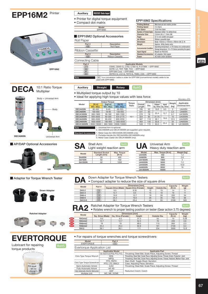
• Printer for digital torque equipment• Compact dot matrix
ModelEPP16M2
Printing Method Mechanical dot matrix printerPrinting Speed 2.5 line/sLine Space 3 dot line baseNumber of Printed Digits Standard letter 16 (letter/line)Character Size 2.6mm (H) x 1.7mm (W)Paper 57.5 mm width roll paperInk Ribbon Ribbon cassette typeDimension Body 155mm x 145mm x 48mm (W, D, H)Weight Approx. 400g (body only)
Environmental ConditionOperating temperature +5-45 Celsius (no condensation)Storage temperature -10-+70 Celsius (excluding the paper)
Input Signal Based on RS232CStandard Accessories AC adapter, Roll paperPower AC100V-240V 50/60Hz
EPP16M2 Specifi cations
EPP16M2 Optional Accessories
10:1 Ratio Torque Multiplier • Multiplied torque output by 10
• Ideal for applying high torque values with less force
DECA
DECA900N
Body + Universal Arm
Body
Universal Arm
1. Metal Case (for DECA450N-DECA900N only)2. Portable Handle (for DECA4500N-DECA9000N only)3. Metal Case Caster (for DECA18000N only)
Standard Accessories
AP/DAP Optional Accessories
Adapter for Torque Wrench Tester
Model Standard Socket Length [mm]
Max. Torque[N·m]
SA400N 50 400SA700N 62 700SA1200N 62 1200
Model Max. Torque [N·m] Weight [kg]UA450N 450 1.2UA900N 900 2.6UA1800N 1800 4UA3000N 3000 7.2UA4500N 4500 10.9UA9000N 9000 18UA18000N 18000 -
Shell ArmLight weight reaction arm
Universal ArmHeavy duty reaction arm SA UA
• For repairs of torque wrenches and torque screwdrivers
Connecting CablePart # Applicable Models379 CEM2, CEM3-G, CTA2, CTB2-G, R-DT999 ➝ EPP16M2380 DOTE, LC, TDT, TME, TCC ➝ EPP16M2381 EPP16M Cord ➝ EPP16M2382 DOTE3-G, LC2-G, TDT3-G, TME2, CD5 ➝ EPP16M2
Accuracy ±5%
ModelOutput Torque
TorqueRatio
Dimension [mm]Weight
[kg]
Applicable Universal Arm
[N·m] [kgf·m] [lbf·ft] Overall Length Dia. Output
Sq. DriveInput
Sq. DriveMin.-Max. Min.-Max. Min.-Max.DECA450N 90-450 9-45 65-325 195 52 19.0 9.5 2 UA450NDECA900N 180-900 18-90 130-650 541 63
25.4 12.73.4 UA900N
DECA1800N 360-1800 36-180 260-1300 270 78 5.7 UA1800NDECA3000N 600-3000 60-300 434-2170 10:1 324 95 31.75
19.0 10 UA3000N
DECA4500N 900-4500 90-450 650-3250 367 110 38.1 12.5 UA4500NDECA9000N 1800-9000 180-900 1300-6500 464 140 50.8
25.434 UA9000N
DECA18000N 3600-18000 360-1800 2600-13000 540 172 63.5 60 UA18000N
Model Part #EVERTORQUE 830
Roll PaperPart # Description408 Roll Paper
Ribbon CassettePart # Description409 Ribbon Cassette
Auxiliary RS232C Data Input
Auxiliary Straight Rotary
381 is a conversion cable in order for EPP16M (conventional model) cable to be used with EPP16M2.
Note
1. Universal Arm is optional.2. DECA9000N and DECA18000N are supplied upon request.
Note
Down Adapter for Torque Wrench Testers
Ratchet Adapter for Torque Wrench Testers
Down Adapter
Ratchet Adapter
• Compact adapter to reduce the size of square drive
• Rotates wrench to proper testing position on tester (Gear action 3.75 degrees)
DA
RA2Model
Dimensions [mm] Capacity WeightSq. Drive (Male) Sq. Drive (Female) Height Outside Dia. [N·m] [kg]
RA3mk2 9.5 9.5 37.3 55 70 0.28RA4mk2 12.7 12.7 52.5 70 220 0.6RA6mk2 19 19 69.3 115 850 2.3RA8mk2 25.4 25.4 92.8 161 2100 6.3RA12 38.1 38.1 111 234 3000 12.6
Model Part #Dimensions [mm] Capacity Weight
Square Drive (Male) Square Drive (Female) Height Outside Dia. [N·m] [g]DA3-2 296 9.5 6.35 12 13 14 5DA4-3 297 12.7 9.5 15 18 70 11DA6-4 298 19.0 12.7 19 28 220 34DA8-6 299 25.4 19.0 26 35 750 66 DA12-8 300 38.1 25.4 44 55 2100 320
RoHS
RoHS
RoHS RoHS
RoHS
RoHS
NEW
NEW
NEW
NEW

68
Tech
nica
l Dat
a
120100110
90
234 1 0
Coupler
Adjusting bar
Coupler
F R E E
LR
Method of setting torque (Adjustable type):1. Turn the locker of the main unit clockwise to release the lock.2. Holding the main scale knurling part with the fingers of your right
hand, turn the grip with the fingers of your left hand to set the torque value.
* Setting the torque set values: (1) Turn the grip to match the top end of the supplemental
graduation with the main scale.(2) Match the supplemental graduation line with the main scale
vertical line (See the figure below).3. After setting the torque, turn the main unit locker
counterclockwise to lock it.
■ LTD, RTD, MLD
Method of setting torque (Preset type):1. Holding the grip with your left hand, insert the adjusting tool bar
into the grooves of the adjustment screw and turn to adjust. Turn clockwise to increase the torque value.
2. Insert with the exclusive bit into the loading device of the Torque Driver Tester (TDT) and fix it.
3. Turn the loading device clockwise to measure the torque value. 4. Continue to repeat procedures 1-3 until the torque is matched.
■ NTD, RNTD
Torque Settings for Torque Screwdrivers
Method of preloading the FTDThe preload function is a function that uses the handle to apply a preloading torque close to that of the measuring point to minimize the twisting angle during measurement.In the FTD series torque screwdrivers, a preload function is provided to prevent your wrist from becoming strained and the torque scale from becoming difficult to read when operating close to the maximum torque.1. Holding the FTD screwdriver with your left hand, turn the
preload handle in the counterclockwise direction using the fingers of your right hand (in case of clockwise measuring).
2. After some slipping turns, the needle will begin to move, and it will be easy to set an optional torque value.
3. If you do not wish to use the preload function, turn the preload handle until there is no tension and the central set indicator (red mark) points to the FREE mark.
■ FTD50-400CN
Method of setting the FTD-S indicator and memory pointer1. Make sure the indicator is pointing to zero by matching the scale.
If not, adjust to zero by lightly pushing down on the scale and rotating it.
2. Turn the memory pointer in the direction opposite to the measuring direction until it matches the main indicator.
3. Carry out torque measurement or torque tightening.
■ FTD-S

69
Tech
nica
l Dat
a
N・m
500
600
700 20
N・m
600
700
500 0
Down
Up
LOCK
020 40
N・m
Up
Down
50 500
500
Glass plate
● QL, CL, YCL, A, etc.1. Release the locker (Turn it counterclockwise).2. Set the torque by turning the supplemental graduation,
confirming the value of the main scale.3. Turn the locker clockwise to lock it. (Change the locker pin
location if the pin is contacted when locking.)
■ Adjustable type
● QLE, CLE, DQLE, etc.1. Insert the adjusting tool supplied as a standard accessory.2. Set the torque by turning the supplemental graduation with the adjusting tool, confirming the value on the main scale.3. No locking mechanism is needed for QLE models.
● PQL, PCL, AC, QSP3, etc.1. Insert the provided hexagon key into the adjusting hexagonal hole.2. Turn the hexagon key to set the torque, confirming the value on the
main scale and supplemental graduation.3. No locking mechanism is needed for PQL models (An adjusting tool
for QSP3 is optional).
■ Pre-lock and preset types
● DB, CDB, T1. For measurement
The scale on the dial gauge can be rotated. Press the dial case from above and turn the pointer to correctly match “0”.
2. Presetting exclusively for tightening Alternatively, the desired torque can be preset on the dial beforehand and then the bolt can be tightened until the pointer shows “0”.
■ Dial Indication types
Torque Settings for Torque Wrenches
Model Adjusting hexagon hole mm size across flats
PQL6N4-PQL25N 2.5
PQL50N-200N44
AC25N-100N

70
Tech
nica
l Dat
a
S.I. unit system Metric unit system American unit systemmN·m cN·m N·m gf·cm kgf·cm kgf·m ozf·in lbf·in lbf・ft
1 mN・m = 1 0.10 0.001 10.2 0.0102 0.000102 0.142 0.00885 0.0007381 cN・m = 10 1 0.01 102 0.102 0.00102 1.42 0.0885 0.007381 N・m = 1000 100 1 10200 10.2 0.102 142 8.85 0.738
1 gf・cm = 0.0981 0.00981 0.0000981 1 0.001 0.00001 0.0139 0.000868 0.00007231 kgf・cm = 98.1 9.81 0.0981 1000 1 0.01 13.9 0.868 0.07231 kgf・m = 9810 981 9.81 100000 100 1 1390 86.8 7.231 ozf・in = 7.06 0.706 0.00706 72.0 0.072 0.00072 1 0.0625 0.005211 lbf・in = 113 11.3 0.113 1150 1.15 0.0115 16 1 0.08331 lbf・ft = 1360 136 1.36 13800 13.8 0.138 192 12 1
Country/Region Japan, China, Europe Asia U.S.A., Aircraft industry
1 [N·m] = 10.1972 [kgf·cm] ≈ 10.20 [kgf·cm] 1 [kgf·cm] = 0.0980665 [N·m] ≈ 0.0981 [N·m] Conversion example: T = 25·0 [kgf·cm] = 25.0 x 0.0980665 = 2.4516625 [N·m] ≈ 2.45 [N·m]
N·mkgf·cm 0 1 2 3 4 5 6 7 8 9
10 0.981 1.08 1.18 1.27 1.37 1.47 1.57 1.67 1.77 1.86
20 1.96 2.06 2.16 2.26 2.35 2.45 2.55 2.65 2.75 2.84
30 2.94 3.04 3.14 3.24 3.33 3.43 3.53 3.63 3.73 3.82
40 3.92 4.02 4.12 4.22 4.31 4.41 4.51 4.61 4.71 4.81
50 4.90 5.00 5.10 5.20 5.30 5.39 5.49 5.59 5.69 5.79
60 5.88 5.98 6.08 6.18 6.28 6.37 6.47 6.57 6.67 6.77
70 6.86 6.96 7.06 7.16 7.26 7.35 7.45 7.55 7.65 7.75
80 7.85 7.94 8.04 8.14 8.24 8.34 8.43 8.53 8.63 8.73
90 8.83 8.92 9.02 9.12 9.22 9.32 9.41 9.51 9.61 9.71
100 9.81 9.90 10.0 10.1 10.2 10.3 10.4 10.5 10.6 10.7
kgf·cmN·m 0 0.1 0.2 0.3 0.4 0.5 0.6 0.7 0.8 0.9
1 10.2 11.2 12.2 13.3 14.3 15.3 16.3 17.3 18.4 19.4
2 20.4 21.4 22.4 23.5 24.5 25.5 26.5 27.5 28.6 29.6
3 30.6 31.6 32.6 33.7 34.7 35.7 36.7 37.7 38.7 39.8
4 40.8 41.8 42.8 43.8 44.9 45.9 46.9 47.9 48.9 50.0
5 51.0 52.0 53.0 54.0 55.1 56.1 57.1 58.1 59.1 60.2
6 61.2 62.2 63.2 64.2 65.3 66.3 67.3 68.3 69.3 70.4
7 71.4 72.4 73.4 74.4 75.5 76.5 77.5 78.5 79.5 80.6
8 81.6 82.6 83.6 84.6 85.7 86.7 87.7 88.7 89.7 90.8
9 91.8 92.8 93.8 94.8 95.9 96.9 97.9 98.9 99.9 101
10 102 103 104 105 106 107 108 109 110 111
N·mkgf·cm 0 10 20 30 40 50 60 70 80 90
100 9.81 10.8 11.8 12.7 13.7 14.7 15.7 16.7 17.7 18.6
200 19.6 20.6 21.6 22.6 23.5 24.5 25.5 26.5 27.5 28.4
300 29.4 30.4 31.4 32.4 33.3 34.3 35.3 36.3 37.3 38.2
400 39.2 40.2 41.2 42.2 43.1 44.1 45.1 46.1 47.1 48.1
500 49.0 50.0 51.0 52.0 53.0 53.9 54.9 55.9 56.9 57.9
600 58.8 59.8 60.8 61.8 62.8 63.7 64.7 65.7 66.7 67.7
700 68.6 69.6 70.6 71.6 72.6 73.5 74.5 75.5 76.5 77.5
800 78.5 79.4 80.4 81.4 82.4 83.4 84.3 85.3 86.3 87.3
900 88.3 89.2 90.2 91.2 92.2 93.2 94.1 95.1 96.1 97.1
1000 98.1 99.0 100 101 102 103 104 105 106 107
kgf·mN·m 0 1 2 3 4 5 6 7 8 9
10 1.02 1.12 1.22 1.33 1.43 1.53 1.63 1.73 1.84 1.94
20 2.04 2.14 2.24 2.35 2.45 2.55 2.65 2.75 2.86 2.96
30 3.06 3.16 3.26 3.37 3.47 3.57 3.67 3.77 3.87 3.98
40 4.08 4.18 4.28 4.38 4.49 4.59 4.69 4.79 4.89 5.00
50 5.10 5.20 5.30 5.40 5.51 5.61 5.71 5.81 5.91 6.02
60 6.12 6.22 6.32 6.42 6.53 6.63 6.73 6.83 6.93 7.04
70 7.14 7.24 7.34 7.44 7.55 7.65 7.75 7.85 7.95 8.06
80 8.16 8.26 8.36 8.46 8.57 8.67 8.77 8.87 8.97 9.08
90 9.18 9.28 9.38 9.48 9.59 9.69 9.79 9.89 9.99 10.1
100 10.2 10.3 10.4 10.5 10.6 10.7 10.8 10.9 11.0 11.1
N·mkgf·m 0 1 2 3 4 5 6 7 8 9
10 98.1 108 118 127 137 147 157 167 177 186
20 196 206 216 226 235 245 255 265 275 284
30 294 304 314 324 333 343 353 363 373 382
40 392 402 412 422 431 441 451 461 471 481
50 490 500 510 520 530 539 549 559 569 579
60 588 598 608 618 628 637 647 657 667 677
70 686 696 706 716 726 735 745 755 765 775
80 785 794 804 814 824 834 843 853 863 873
90 883 892 902 912 922 932 941 951 961 971
100 981 990 1000 1010 1020 1030 1040 1050 1060 1070
kgf·mN·m 0 10 20 30 40 50 60 70 80 90
100 10.2 11.2 12.2 13.3 14.3 15.3 16.3 17.3 18.4 19.4
200 20.4 21.4 22.4 23.5 24.5 25.5 26.5 27.5 28.6 29.6
300 30.6 31.6 32.6 33.7 34.7 35.7 36.7 37.7 38.7 39.8
400 40.8 41.8 42.8 43.8 44.9 45.9 46.9 47.9 48.9 50.0
500 51.0 52.0 53.0 54.0 55.1 56.1 57.1 58.1 59.1 60.2
600 61.2 62.2 63.2 64.2 65.3 66.3 67.3 68.3 69.3 70.4
700 71.4 72.4 73.4 74.4 75.5 76.5 77.5 78.5 79.5 80.6
800 81.6 82.6 83.6 84.6 85.7 86.7 87.7 88.7 89.7 90.8
900 91.8 92.8 93.8 94.8 95.9 96.9 97.9 98.9 99.9 101
1000 102 103 104 105 106 107 108 109 110 111
Torque Conversion List
■ Unit of Torque and Conversion Values
JCSS (Japan Calibration Service System) Tohnichi Mfg. Co. Ltd’s torque standards calibration laboratory is now an authorized calibration service provider of JCSS (Japan Calibration Service System) under Japanese measurement law. (Registration number: JCSS0281)Based on this, Tohnichi has launched a JCSS calibration service for DOTE3-G torque wrench testers from 10 N·m to 1000 N·m as a validated JCSS system and an uncertainty certificate service for outside of the above stated torque range.Tohnichi issued JCSS calibration certificate is recognized internationally based on mutual recognition arrangement (MAR) of ILAC (International Laboratory Accreditation Cooperation) and APLAC (Asia Pacific Laboratory Accreditation Cooperation) by IAJapan.

71
Tech
nica
l Dat
a
Calibration Certificate● Torque wrenches are measuring instruments. The calibration certificate is the document which certifies
the accuracy of the torque products, which are traceable to Japanese national standards. Please keep the calibration certificate for future use.
● Accuracy % is calculated on each indicated value. Accuracy stated as “+/- a percentage + 1 digit” indicates that digital display will round up to next digit in resolution if value falls between digits.
● Tohnichi’s torque products provided with a calibration certificate can be used immediately at ISO9000 facilities without the need for further acceptance inspection or any additional certifications.
● The calibration certificate is effective for 3 years from the date of inspection or 1 year from the date of first use. Therefore, please fill in the date in the calibration certificate when first used.
● Tohnichi’s manual torque tools are normally guaranteed to 100,000 tightening cycles or 1 year. For click type torque wrenches, it can be also used up to 1,000,000 tightening cycles if the function is properly maintained and adjusted at every 100,000 cycles.
Standard Tightening TorqueStandard tightening torque [N·m] Standard tightening torque [kgf·cm]
Nominal diameter T[N·m]
0.5T series[N·m]
1.8T series[N.m]
2.4T series[N.m]
M1 0.0195 0.0098 0.035 0.047(M1.1) 0.027 0.0135 0.049 0.065 M1.2 0.037 0.0185 0.066 0.088(M1.4) 0.058 0.029 0.104 0.140 M1.6 0.086 0.043 0.156 0.206(M1.8) 0.128 0.064 0.23 0.305 M2 0.176 0.088 0.315 0.42(M2.2) 0.23 0.116 0.41 0.55 M2.5 0.36 0.18 0.65 0.86 M3 0.63 0.315 1.14 1.50(M3.5) 1 0.5 1.8 2.40 M4 1.5 0.75 2.7 3.6(M4.5) 2.15 1.08 3.9 5.2 M5 3 1.5 5.4 7.2 M6 5.2 2.6 9.2 12.2(M7) 8.4 4.2 15 20.0 M8 12.5 6.2 22 29.5 M10 24.5 12.5 44 59 M12 42 21 76 100(M14) 68 34 122 166 M16 106 53 190 255 M18 146 73 270 350 M20 204 102 370 490(M22) 282 140 500 670 M24 360 180 650 860(M27) 520 260 940 1240 M30 700 350 1260 1700(M33) 960 480 1750 2300 M36 1240 620 2250 3000(M39) 1600 800 2900 3800 M42 2000 1000 3600 4800(M45) 2500 1260 4500 6000 M48 2950 1500 5300 7000(M52) 3800 1900 6800 9200 M56 4800 2400 8600 11600(M60) 5900 2950 10600 14000 M64 7200 3600 13000 17500(M68) 8800 4400 16000 21000
■ Screws and Applicable “T” Series
Standard bolt stress: 210 [N/mm2 ] Stress area of bolt (JIS B 1082) Note: Conversion values rolled up to effective 3-digits.
Nominal diameter T[kgf.cm]
0.5T series[kgf.cm]
1.8T series[kgf.cm]
2.4T series[kgf.cm]
M1 0.199 0.100 0.357 0.479(M1.1) 0.275 0.138 0.500 0.663 M1.2 0.377 0.189 0.673 0.897(M1.4) 0.591 0.296 1.06 1.43 M1.6 0.877 0.438 1.59 2.10(M1.8) 1.31 0.653 2.35 3.11 M2 1.79 0.897 3.21 4.28(M2.2) 2.35 1.17 4.18 5.61 M2.5 3.67 1.84 6.63 8.77 M3 6.42 3.21 11.6 15.3(M3.5) 10.2 5.1 18.4 24.5 M4 15.3 7.6 27.5 36.7(M4.5) 21.9 11.0 39.8 53.0 M5 29.4 14.7 53.0 70.6 M6 53.0 26.5 93.8 124(M7) 85.7 42.8 153 204 M8 127 63.2 224 301 M10 250 127 449 602 M12 428 214 775 1020(M14) 693 347 1240 1690 M16 1080 540 1940 2600 M18 1490 744 2750 3570 M20 2080 1040 3770 5000(M22) 2880 1430 5100 6830 M24 3670 1840 6630 8770(M27) 5300 2650 9590 12600 M30 7140 3570 12800 17300(M33) 9790 4890 17800 23500 M36 12600 6320 22900 30600(M39) 16300 8160 29600 38700 M42 20400 10200 36700 48900(M45) 25500 12800 45900 61200 M48 30100 15300 54000 71400(M52) 38700 19400 69300 93800 M56 48900 24500 87700 118000(M60) 60200 30100 108000 143000 M64 73400 36700 133000 178000(M68) 89700 44900 163000 214000
Standard T series 0.5T series 1.8T series 2.4T series Applicable screws (Strengths) (Material)
4.6-6.8SS, SC, SUS
-Brass, Copper, Aluminum
8.8-12.9SCr, SNC, SCM
10.9-12.9SCr, SNC, SCM, SNCM
Axial tension standard value [N/mm2] Min - Max
210300-160
105150-80
380540-290
500710-380
ApplicationTo be applied to ordinary screws, unless otherwise specified
Male and female screws with copper, aluminum or plastic, for die-cast plastic products
Durable screw joints made of special steel including those affected by additional dynamic loads (Friction clamping)
Applicable products Ordinary products Electronic products Vehicles, Engines Construction products * The maximum to the minimum of the axial stress is considered as the dispersion of the torque coefficient.
Example: max = 210 × (0.2/0.14) = 300 [N/mm2] Torque coefficient: 0.14 (minimum) - 0.2 (average) - 0.26 (maximum)
(Reference value) (Reference value)
Restriction of Hazardous Substances Directive (RoHS)Following RoHS, which restricts the use of certain hazardous materials in product manufacturing, Tohnichi has expanded its efforts in environmentally friendly procurement. Starting with our Product Catalog 2011 edition, the RoH mark is shown on all applicable models conforming to the RoHS directive. For details, please contact Tohnichi.
RoHS

72
Tech
nica
l Dat
a
Tohnichi's Worldwide Services System
Torque equipment must have durability, ease-of-use, and even more importantly, high accuracy.To insure high accuracy, torque products should be properly used and maintained throughout the lifetime of the equipment. Tohnichi has created an international service network to provide customers with a variety of after sales services.
1. Tohnichi's International Service Network
As a world leading torque equipment brand, Tohnichi has developed sales and service agents.Our agencies operate in 50 countries or regions through hundreds of dealers supplying products and also repair services to customers around a world.
[Tohnichi Web Homepage]http://tohnichi.jp/english/index.html
TohnichiShanghai
Tohnichi Europe Tohnichi
America
Atlanta
Tohnichi Japan[Headquarter]
Worldwide Services are provided by Tohnichi global network[Tohnichi Japan] Regions of Asia, Oceania, Middle east, & Africa[Tohnichi Shanghai] China[Tohnichi America] Regions of North and South America, Canada[Tohnichi Europe] Regions of Europe and Russia
Stuttgart
Tohnichi Worldwide NetworkFind a Tohnichi representative in your area!
Parts ListMaintenance for Tohnichi torque products
[Registration is required for download services]

73
Tech
nica
l Dat
a
2. Tohnichi Web Parts List/Parts Supplies
Detailed parts information is available through Tohnichi's website.Search by Model or Part name. View detailed tool diagrams: click and select parts to create a convenient list for parts ordering (Your Parts List).
[Search Model from Parts]Enter parts No.
[Search Parts from Model]Enter model name.
[Parts List Top Page]
[Parts List]