BRUSHLESS SECTION Brushless DC ProductsBrushless Motor Construction Because most people who work...
20
BRUSHLESS SECTION 4 COLOR SEPARATOR Brushless DC Products • Ideal for continuous duty applications • Better performance than permanent magnet DC systems. No brushes to replace. • Low-voltage 24V models available. • Over 50 Integramotor models in this issue. • Proven system solutions. High-speed designs available. • Economical alternative to stepper and servo systems.
Transcript of BRUSHLESS SECTION Brushless DC ProductsBrushless Motor Construction Because most people who work...

B R U S H L E S S S E C T I O N4 C O L O R S E P A R A T O R
Bru
shle
ss D
C P
roduct
s• Ideal for continuous duty
applications
• Better performance than permanent magnet DC systems. No brushes to replace.
• Low-voltage 24V models available.
• Over 50 Integramotor models in this issue.
• Proven system solutions. High-speed designs available.
• Economical alternative to stepper and servo systems.

www.bodine-electric.com Catalog S-16 104
R
MADE IN U.S.A.
Brushless DC MotorsTechnical Information
Figure 1: Figure 2: Commutation Methods
PMDC Motor
Brushless MotorBrushless Motor
PMDC Motor
Basic Motor Construction
Typical ApplicationsBrushless DC motors are well-suited for applications that require very high speeds, where a brush-type motor would generate a loud noise and wear out brushes very quickly. Examples include centrifuges, grinders, and fans.
Because brushless DC motor speed controls rely on Hall sensor feedback for speed regulation instead of back-EMF, there is only minimal speed drift as the motor warms up. This is benefi cial in applications where the speed can’t deviate from its setting from the time the machine is turned on until the time it is turned off. Examples include fi lm processors, com-mercial food ovens, and medical pumps.
The low inertia of the brushless DC motor, coupled with the high peak torque capacity, result in a motor capable of quick accelerations and decelerations. This makes them an excellent choice in “servo” type applications where quick and precise position-ing is needed. Examples include screen printing machinery, material handling equipment, and offi ce machinery.
except that the winding phases are switched on and off electronically by means of a control device. The control “knows” when to switch the windings because of feedback it receives from rotor position Hall effect sensors.
Benefi ts of Brushless• Having the winding, which is the heat-gener-
ating part of the motor, closer to the outside surface of the motor results in a motor that dis-sipates heat well and that can therefore handle higher continuous loads without exceeding its tem perature limit.
• Having no brushes results in a motor that requires less maintenance and that has a longer life because there are no brushes or commuta-tor to wear out.
• The absence of brushes also results in a motor that is quieter because there is no sliding friction to create audible noise and no current arcing across an air gap to create electrical noise.
• There is also no brush dust generated by a brushless motor, so they won’t contaminate a clean room environment.
• The lower inertia of a brushless rotor, compared to a wound armature, results in a motor that can accelerate and decelerate quickly.
Brushless Motor ConstructionBecause most people who work with motors are famil-iar with brush-type permanent magnet (PM) motors, it is helpful to explain the construction of a brushless DC (BLDC) motor by comparing it to the PM motor. BLDC motors are sometimes referred to as “inside-out PM motors” because their speed-torque curves are very similar to those of PM motors. However, BLDC motors have their magnets on the rotating part of the motor instead of on the stationary part. Accordingly, they have their windings on the stationary part of the motor instead of on the rotating part, as in a PM motor. Figure 1 shows the construction differences between the BLDC and the PM motors.
The other major construction difference is the means for switching winding phases on and off, as shown in Figure 2. A PM motor uses brushes that press against a commutator attached to the armature. As the armature turns, the brushes come into contact with different segments of the commutator and change the current path through the winding. The interaction between the magnetic fi eld created in the armature and the permanent magnet fi eld in the stationary part of the motor results in rotation of the armature. Operation of a BLDC motor is similar

Catalog S-16 www.bodine-electric.com 105
R
MADE IN U.S.A.
In
dex
Bru
shle
ss D
C Pe
rman
ent M
agne
t DC
AC
Indu
ctio
n
Pace
sette
r™ In
vert
er D
uty
Cust
om
Hol
low
Sha
ft IN
TEG
RAm
otor
™
e-TO
RQ™
N
ew
Bodine 24 Volt motors and gearmotors have four 18 AWG wires and a fi ve-conductor shielded cable for connection to a Bodine 24 Volt control. The three motor phase connections are made with .250” quick connect
receptacles. The ground lead is term inated with a ring terminal and the 24 AWG commutation leads inside the 5-conductor shielded cable are terminated in a 6-pin in-line connector with 0.1” center distances.
The harness is a nominal 24” long from the motor housing to the end of the connections.
Wiring Harness for 24 Volt Motors and Gearmotors
Wiring Harness for 130 Volt Motors and Gearmotors (34B shown)
Brushless DC Motors Electrical Connections
Pin Wire Color Pin Part No. Connector Function Location & Size Part No. – Red, 18 AWG – AMP 640902-1 Phase B – Brown, 18 AWG – AMP 640902-1 Phase A – Orange, 18 AWG – AMP 640902-1 Phase C – Green/Yellow, 18 AWG – AMP 640204-1 Earth /Ground 1 Drain Wire MOLEX 08-50-0113 Shield Drain 2 Black, 24 AWG MOLEX 08-50-0113 Sensor Common 3 Green, 24 AWG MOLEX 08-50-0113 Hall C 4 White, 24 AWG MOLEX 08-50-0113 MOLEX 22-01-3067 Hall B 5 Brown, 24 AWG MOLEX 08-50-0113 Hall A 6 Red, 24 AWG MOLEX 08-50-0113 Sensor Power
needed between the motor and the control. This cable may be supplied by the customer or it can be purchased from Bodine Electric. Model 3983 is a 6’ long cable that can be used to connect 130 Volt motors and gearmotors to Bodine control models
Bodine 130 Volt motors and gearmotors have a single 14-pin plug & twist connector at the end of a nominal 12” long harness. This provides a quick and easy means of connecting the motor or gearmotor to a Bodine 115 VAC control. An interface cable is
Wiring Harness for 130 Volt Motors and Gearmotors3910, 3911, and 3921. Model 3982 is a 6’ long cable that can be used to connect 130 Volt motors and gearmotors to Bodine control model 3912. It can also be used as an extension cable for use with any of the above mentioned controls. Encased model 3912 includes a 6' cable.
Pin Wire Color Pin Part No. Connector Function Location & Size Part No. 2 Red, 18 AWG AMP 66098-7 Phase B 1 Brown, 18 AWG AMP 66098-7 Phase A 3 Orange, 18 AWG AMP 66098-7 Phase C 4 Green/Yellow, 18 AWG AMP 66098-7 Earth Ground 11 Drain Wire AMP 66102-7 AMP 206044-1 Shield Drain 10 Black, 24 AWG AMP 66102-7 Sensor Common 14 Green, 24 AWG AMP 66102-7 Hall C 13 White, 24 AWG AMP 66102-7 Hall B 12 Brown, 24 AWG AMP 66102-7 Hall A 9 Red, 24 AWG AMP 66102-7 Sensor Power
Wiring Harness for 24 Volt Motors and Gearmotors (34B shown)
13
44 8 1214117
12 +2/-1
24 +2/-1
PIN 1

www.bodine-electric.com Catalog S-16 106
R
MADE IN U.S.A.
22B Motor
Brushless DC Motors1/16 - 1/5 HP
130V design shown with optional “accessory ready” mounting holes
“S” (4) .164-32 UNC-2B, .25 in. deep minimum on 2.626 in. BC.“H” See page 105 for cable length and details.
XH MAX. .94±.03
.125±.010
.91±.05
.81±.02
.347FLAT
.3745
.3740.2498.2493
2.47 MAX..999/.995
2.63
MA
X.
“S”
“H”
This surface machined only onmodels with accessory shaft.
29.5°30.5°
(2) #6-32 x .19 deep min.180° apart on 1.269/1.279 B.C.
130 Volt Winding24 Volt Winding
Speed Rated Motor Torque Voltage Winding Winding Rotor Radial Length Wt. Product No No (rpm) Torque HP Constant Constant Res. Induct. Inertia Load XH (lbs.) Type Acc’y. Acc’y. Acc’y. Acc’y. (oz-in.) (oz-in./A) (V/krpm) (ohms) (mH) (oz-in.-sec.2) (lbs.) (inch) Shaft Shaft Shaft Shaft 2500 25 1/16 8.4 5.8 1.2 2.1 .0036 25 3.67 2.5 22B2BEBL N3602 3502 – – 2500 25 1/16 47 35 40 70 .0036 25 3.67 2.5 22B2BEBL – – – 3302 2500 50 1/8 9.0 6.7 .52 1.1 .0072 25 4.63 3.5 22B4BEBL 3604 N3504 – – 2500 50 1/8 50 37 15 40 .0072 25 4.63 3.5 22B4BEBL – – 3404 3304 10,000 20 1/5 14 9.8 4.8 10 .0072 25 4.63 3.5 22B4BEBL – – – 3314
Model Number1
1 NOTE: Model numbers shown in bold type are in stock. “N” model numbers require lead time and minimum quantities.
22B121 for specifi c unfi ltered ratings)
• May be operated above ratings if duty is intermit-tent and/or if heat sink is provided (consult a Bodine applications engineer fi rst)
• Face mounting is standard
Optional Accessories• 360 pulse/revolution optical encoder model 0940, see
page 122 (requires adaptor plate model 0993 also)• Cable model 3983 for connecting 130V motors to
Bodine chassis controls, see page 122• Adaptor model 0993 for mounting encoder,
see page 122
Matching Controls• Motors may be used with a variety of controls,
including servo amplifi ers, that produce square-wave current for 3-phase, 4-pole brushless motors with 60° commutation
• Bodine stocks a full line of single-quadrant speed controls ideally matched for Bodine’s brushless mo-tors, see pages 114-121
Standard Features• Totally Enclosed, Non-Ventilated • IP-44, 130V models only• Plug-in connectors facilitate electrical connections• Electronic commutation provides quiet operation
and low electro-magnetic interference (EMI) while eliminating brush maintenance and contamination from brush dust
• Molded hall sensor assembly for accurate com-mutation
• Wound stator with exposed laminations provides excellent heat transfer and allows maximum power per motor frame size
• Rare earth magnets on the rotor provide high torque and low rotor inertia
Application Information• Brushless motors require a control• Electrical connections shown on page 105• Performance ratings based on 115° C winding,
25° C ambient, and no heat sink• May have to be operated below ratings if unfi ltered
control is used and if duty is continuous (see page
THREEB O D I N E
DIMENSIONS
ONLINE

Catalog S-16 www.bodine-electric.com 107
R
MADE IN U.S.A.
In
dex
Bru
shle
ss D
C Pe
rman
ent M
agne
t DC
AC
Indu
ctio
n
Pace
sette
r™ In
vert
er D
uty
Cust
om
Hol
low
Sha
ft IN
TEG
RAm
otor
™
e-TO
RQ™
N
ew
34B Motor shown with optional “L” bracket (model 0979) and optional “accessory ready” mounting holes
Brushless DC Motors1/5 - 3/8 HP
“S” (4) .250-20 UNC-2B, .31 in. deep minimum on 2.750 in. BC.“H” See page 105 for cable length and details.
(2) #4-40 UNC-2B x.19" DEEPHOLES ON 1.812 B.C.
(2) 6-32 UNC-2B x .19" DEEP HOLES ON 1.274 B.C.
This surface machined only onmodels with accessory shaft.
1.875 REF.3.750 REF.
4.53 REF.
2.12
+.0
0/.0
6
1.625±.03.09 REF.
1.38±.02
.5000
.4995
.448REF.
XH MAX.
4.02
DIA
. MA
X.
.2498
.2493
.695±.045
1.875±.030 1.50±.03 .23MAX.3.75 REF.4 HOLES
.281 I.D. REF.
“S”
2.0001.997
“H”
34B
130 Volt Winding24 Volt Winding
Speed Rated Motor Torque Voltage Winding Winding Rotor Radial Length Wt. Product No No (rpm) Torque HP Constant Constant Res. Induct. Inertia Load XH (lbs.) Type Acc’y. Acc’y. Acc’y. Acc’y. (oz-in.) (oz-in./A) (V/krpm) (ohms) (mH) (oz-in.-sec.2) (lbs.) (inch) Shaft Shaft Shaft Shaft 2500 81 1/5 8.8 6.6 .3 .54 .0115 42 4.06 6.0 34B3BEBL 3600 3500 – – 2500 81 1/5 51 38 9.2 24 .0115 42 4.06 6.0 34B3BEBL – – 3406 3306 2500 101 1/4 9.0 6.7 .17 .40 .0154 42 4.56 7.0 34B4BEBL – N3507 – – 2500 101 1/4 51 38 5.8 14 .0154 42 4.56 7.0 34B4BEBL – – – 3307 2500 151 3/8 9.0 6.7 .087 .246 .0215 42 5.56 9.0 34B6BEBL N3609 N3509 – – 2500 151 3/8 57 42 3.4 11 .0215 42 5.56 9.0 34B6BEBL – – 3409 3309 10,000 33 1/3 14.5 10.7 1.7 4.6 .0154 42 4.56 7.0 34B4BEBL – – – 3317
Model Number1
1 NOTE: Model numbers shown in bold type are in stock. “N” model numbers require lead time and minimum quantities.
Standard Features• Totally Enclosed, Non-Ventilated (IP-44)• Plug-in connectors facilitate electrical connections• Electronic commutation provides quiet operation
and low electromagnetic interference (EMI) while eliminating brush maintenance and contamination from brush dust
• Molded hall sensor assembly for accurate commuta-tion
• Wound stator with integrally cast cooling fi ns pro-vides excellent heat transfer and allows maximum power per motor frame size
• Rare earth magnets on the rotor provide high torque and low rotor inertia
Application Information• Brushless motors require a control• Electrical connections shown on page 105• Performance ratings based on 115° C winding, 25° C
ambient, and no heat sink• May have to be operated below ratings if unfi ltered
control is used and if duty is continuous (see page
121 for specifi c unfi ltered ratings)• May be operated above ratings if duty is inter-
mittent and/or if heat sink is provided (consult a Bodine applications engineer fi rst)
• Face mounting is standard
Optional Accessories• 360 pulse/revolution optical encoder model 0940, see page 122• Cable model 3983 for connecting 130V motors to
Bodine chassis controls, see page 122• “L” bracket kit model 0979 permits base, ceiling,
and sidewall mounting, see page 122
Matching Controls• Motors may be used with a variety of controls, in-
cluding servo amplifi ers, that produce square-wave current for 3-phase, 4-pole brushless motors with 60° commutation
• Bodine stocks a full line of single-quadrant speed controls ideally matched for Bodine’s brushless motors , see pages 114-121
THREEB O D I N E
DIMENSIONS
ONLINE
www.bodine-electric.com Catalog S-16 108
R
MADE IN U.S.A.
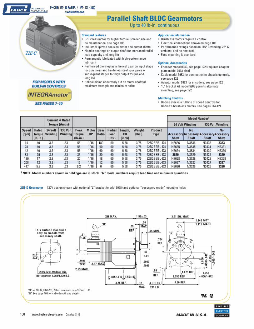
22B-D Gearmotor 130V design shown with optional “L” bracket (model 5968) and optional “accessory ready” mounting holes
Parallel Shaft BLDC GearmotorsUp to 40 lb-in. continuous
“S” (4) 10-32, UNF-2B, .38 in. minimum on a 3.75 in. B.C.“H” See page 105 for cable length and details.
XH MAX.
.2498
.2493
2.63 MAX.
2.47 MAX.
.91±.05
.75 MIN.
.45±.01
.5000
.4999
.19MAX.
1.50±.031.875±.010
3.75 REF.
3.41 SQ. MAX.1.1401.111
1.250+.000/-.042
2.00
0+.
000/
-.04
22.
750
+.00
0/-.
042
1.875 REF.3.750 REF.
4.50 REF.
.09
REF.
4 HOLES.281 I.D.
“S”
1.56±.03
.09REF.
.56MAX.
.744REF.
NOTMACH.
This surface machinedonly on models with
accessory shaft.
29.5°30.5°
(2) #6-32 x .19 deep min.180° apart on 1.269/1.279 B.C.
“H”
130 Volt Winding24 Volt WindingCurrent @ RatedTorque (Amps)
Speed Rated 24 Volt 130 Volt Peak Motor Gear Radial Length, Weight Product No No (rpm) Torque Winding Winding Torque HP Ratio Load XH (lbs.) Type Accessory Accessory Accessory Accessory (lb-in.) (lb-in.) (lbs.) (inch) Shaft Shaft Shaft Shaft 14 40 3.3 .53 55 1/16 180 60 5.58 3.75 22B2BEBL-D4 N3636 N3536 N3433 3333 28 40 3.3 .53 55 1/16 90 60 5.58 3.75 22B2BEBL-D4 N3635 N3535 N3431 N3331 42 40 3.3 .53 55 1/16 60 60 5.58 3.75 22B2BEBL-D3 N3634 N3534 N3430 N3330 83 29 3.3 .53 33 1/16 30 60 5.58 3.75 22B2BEBL-D3 3629 N3529 N3429 3329 139 17 3.3 .53 20 1/16 18 60 5.58 3.75 22B2BEBL-D3 N3628 N3528 N3428 N3328 208 12 3.3 .53 13 1/16 12 60 5.58 3.75 22B2BEBL-D3 N3627 N3527 N3427 3327 417 5.8 3.3 .53 6.2 1/16 6 60 5.58 3.75 22B2BEBL-D3 N3626 N3526 N3426 3326
Model Number1
1 NOTE: Model numbers shown in bold type are in stock. “N” model numbers require lead time and minimum quantities.
22B-D
Application Information• Brushless motors require a control.• Electrical connections shown on page 105• Performance ratings based on 115° C winding, 25° C
ambient, and no heat sink• Face mounting is standard
Optional Accessories• Encoder model 0940, see page 122 (requires adaptor
plate model 0993 also)• Cable model 3983 for connection to chassis controls,
see page 122• Adaptor model 0993 for encoders, see page 122• ”L“ bracket kit model 5968 permits alternate
mounting, see page 122
Matching Controls• Bodine stocks a full line of speed controls for
Bodine‘s brushless motors, see pages 114-121
Standard Features• Brushless motor for higher torque, smaller size and
no maintenance, see page 106• Industrial lip type seals on motor and output shafts• Needle bearings on output shaft for in creased radial
load capacity and long life• Permanently lubricated with high-performance
lubricant• Reinforced thermoplastic helical gear on input stage
for quietness and hardened steel spur gears on subsequent stages for high output torque and long life
• Helical pinion accurately cut on motor shaft for maximum strength and minimum noise

Catalog S-16 www.bodine-electric.com 109
R
MADE IN U.S.A.
In
dex
Bru
shle
ss D
C Pe
rman
ent M
agne
t DC
AC
Indu
ctio
n
Pace
sette
r™ In
vert
er D
uty
Cust
om
Hol
low
Sha
ft IN
TEG
RAm
otor
™
e-TO
RQ™
N
ew
Parallel Shaft BLDC GearmotorsUp to 100 lb-in. continuous
“S” (4) 10-32, UNF-2B, .38 in. minimum on a 3.75 in. B.C.“H” See page 105 for cable length and details.
22B-Z Gearmotor 130V design shown with optional “L” bracket (model 5968) and optional “accessory ready” mounting holes
130 Volt Winding24 Volt WindingCurrent @ RatedTorque (Amps)
Speed Rated 24 Volt 130 Volt Peak Motor Gear Radial Length, Weight Product No No (rpm) Torque Winding Winding Torque HP Ratio Load XH (lbs.) Type Accessory Accessory Accessory Accessory (lb-in.) (lb-in.) (lbs.) (inch) Shaft Shaft Shaft Shaft 14 100 – .76 115 1/11 180 110 7.29 5.25 22B3BEBL-Z4 – – N3463 3363 14 100 3.3 .53 115 1/16 180 110 6.81 4.75 22B2BEBL-Z4 – N3563 – – 21 100 3.3 .53 115 1/16 120 110 6.81 4.75 22B2BEBL-Z4 – N3564 – N3364 28 100 4.4 .76 115 1/11 90 110 7.29 5.25 22B3BEBL-Z4 – – N3462 N3362 28 97 3.3 .53 115 1/16 90 110 6.81 4.75 22B2BEBL-Z4 – N3562 – – 42 95 4.4 .76 115 1/11 60 110 7.29 5.25 22B3BEBL-Z3 3661 N3561 N3461 N3361 83 52 4.4 .76 59 1/11 30 125 7.29 5.25 22B3BEBL-Z3 N3660 N3560 N3460 N3360 139 31 4.4 .76 38 1/11 18 125 6.39 5.25 22B3BEBL-Z2 N3659 N3559 N3459 N3359 208 20 4.4 .76 25 1/11 12 120 6.39 5.25 22B3BEBL-Z2 N3658 N3558 N3458 3358 417 10 4.4 .76 13 1/11 6 100 6.39 5.25 22B3BEBL-Z2 N3657 N3557 N3457 3357
Model Number1
1 NOTE: Model numbers shown in bold type are in stock. “N” model numbers require lead time and minimum quantities.
XH MAX.
.2498
.2493
”H“
2.63 MAX.
2.47 MAX.
.91±.05
1.56REF.
.09REF.
.75REF.
.125/.123SQ. KEY
.78
.5000
.4995
.19 MAX.
3.40 MAX.
.45REF.
1.1401.115
2.75
+.0
0/-.
042
2.00
+.00
/-.0
42
1.25+.00/-.042
1.875REF.
3.750 REF.4.50 REF..09 REF.
1.50±.03
1.875±.030
3.75 REF.
NOTMACH.
.30MAX.
“S”.744REF.
4 HOLES.281 I.D.
MIN. FULLDEPTH OF FLAT
This surface machinedonly on models with
accessory shaft.
29.5°30.5°
(2) #6-32 x .19 deep min.180° apart on 1.269/1.279 B.C.
22B-Z
• Performance ratings based on 115° C winding, 25° C ambient, and no heat sink
• Face mounting is standard
Optional Accessories• Encoder model 0940, see page 122 (requires adap-
tor plate model 0993 also)• Cable model 3983 for connection to chassis con-
trols, see page 122• Adaptor model 0993 for encoders, see page 122• “L” bracket kit model 5968 permits alternate
mounting, see page 122
Matching Controls• Bodine stocks a full line of speed controls for
Bodine’s brushless motors, see pages 114-121
Standard Features• Brushless motor for higher torque, smaller size and
no maintenance, see page 106• Industrial lip type seals on motor and output shafts• Needle bearings on output shaft for increased radial
load capacity and long life• Permanently lubricated with high-performance
lubricant• Wide reinforced thermoplastic helical gear on input
stage for quietness and wide hardened steel spur gears on subsequent stages for high output torque and long life
• Helical pinion accurately cut on motor shaft for maximum strength and minimum noise
Application Information• Brushless motors require a control• Electrical connections shown on page 105

www.bodine-electric.com Catalog S-16 110
R
MADE IN U.S.A.
Parallel Shaft BLDC GearmotorsUp to 200 lb-in. continuous
“S”(4) .250-28, UNF-2B, .50 in. minimum on a 4.78 in. B.C.“H” See page 105 for cable length and details.
Current @ RatedTorque (Amps) 130 Volt Winding24 Volt Winding
Speed Rated 24 Volt 130 Volt Peak Motor Gear Radial Length, Weight Product No No (rpm) Torque Winding Winding Torque HP Ratio Load XH (lbs.) Type Accessory Accessory Accessory Accessory (lb-in.) (lb-in.) (lbs.) (inch) Shaft Shaft Shaft Shaft 8 175 9.6 1.6 210 1/5 312.4 130 6.54 9.0 34B3BEBL-W4 N3647 N3547 N3447 N3347 14 166 9.6 1.6 207 1/5 172.1 130 6.54 9.0 34B3BEBL-W4 N3624 N3524 N3446 3346 26 154 9.6 1.6 190 1/5 97.5 140 6.54 9.0 34B3BEBL-W4 N3656 N3556 N3456 N3356 38 143 9.6 1.6 157 1/5 65.5 140 6.54 9.0 34B3BEBL-W3 N3617 N3517 N3455 N3355 84 65 9.6 1.6 71 1/5 29.7 160 6.54 9.0 34B3BEBL-W3 N3653 N3553 N3453 3353 122 46 9.6 1.6 52 1/5 20.4 60 6.54 9.0 34B3BEBL-W2 N3652 N3552 N3452 3352 266 21 9.6 1.6 24 1/5 9.4 80 6.54 9.0 34B3BEBL-W2 N3623 N3523 N3450 N3350 456 12 9.6 1.6 14 1/5 5.5 90 6.54 9.0 34B3BEBL-W2 3611 N3522 N3449 N3349
34B-W Gearmotor shown with optional “L” bracket (model 0970) and optional “accessory ready” mounting holes
1 NOTE: Model numbers shown in bold type are in stock. “N” model numbers require lead time and minimum quantities.
Model Number1
XH MAX.
4.02
DIA
. MA
X.
.2498
.2493
.695±.045
2.00±.03
.59MAX.1.12REF. .1875/ .1855
SQ. KEY
.6250
.6245
1.50±.03
1.625±.03
3.62 REF.
4 SLOTS.281 WIDE
.16 REF.2.53 MAX.
2.00REF.
4.00 REF.
4.76 REF.
.16REF.
3.50
+.00
/ -
.08
2.67+.00 / -.08
1.85+.00 / -.08
4.08 SQ. MAX.
1.31MAX.
NOTMACH.
“S”
.825REF.
(2) #4-40 UNC-2B x.19"DEEP HOLES ON 1.812 B.C.
(2) 6-32 UNC-2B x .19" DEEPHOLES ON 1.274 B.C.
This surface machinedonly on models with
accessory shaft.
“H”
34B-W
• Performance ratings based on 115° C winding, 25° C ambient, and no heat sink
• Face mounting is standard
Optional Accessories• Encoder model 0940, see page 122• Cable model 3983 for connection to chassis controls,
see page 122• L-Bracket kit model 0970 permits alternate mounting,
see page 122• Adaptor plate kit model 0995 provides for drop-in
replacement of competitive gearmotors, see page 122
Matching Controls• Bodine stocks a full line of speed controls for
Bodine’s brushless motors, see pages 114-121
Standard Features• Brushless motor for higher torque, smaller size and
no maintenance, see page 107• Industrial lip type seals on motor and output shafts• Needle bearings on output shaft for increased radial
load capacity and long life• Permanently lubricated with high-performance
lubricant• Nylon helical gear on input stage for quietness and
hardened steel spur gears on subsequent stages for high output torque and long life
• Helical pinion accurately cut on motor shaft for maximum strength and minimum noise
Application Information• Brushless motors require a control• Electrical connections shown on page 105

Catalog S-16 www.bodine-electric.com 111
R
MADE IN U.S.A.
In
dex
Bru
shle
ss D
C Pe
rman
ent M
agne
t DC
AC
Indu
ctio
n
Pace
sette
r™ In
vert
er D
uty
Cust
om
Hol
low
Sha
ft IN
TEG
RAm
otor
™
e-TO
RQ™
N
ew
Parallel Shaft BLDC GearmotorsUp to 350 lb-in. continuous
“S” (4) .1/4-28 UNF-2B, .50 in. minimum on a 5.13 in. B.C.“H” See page 105 for cable length and details.
34B-E Gearmotor shown with optional “L” bracket (model 0969) and optional “accessory ready” mounting holes
Current @ RatedTorque (Amps)
Speed Rated 24 Volt 130 Volt Peak Motor Gear Radial Length, Weight Product No No (rpm) Torque Winding Winding Torque HP Ratio Load XH (lbs.) Type Accessory Accessory Accessory Accessory (lb-in.) (lb-in.) (lbs.) (inch) Shaft Shaft Shaft Shaft 8.3 310 9.6 1.6 475 1/5 300 220 6.689 11.0 34B3BEBL-E4 – N3575 – N3375 14 341 9.6 1.6 475 1/5 180 200 6.689 11.0 34B3BEBL-E4 – N3574 – 3374 21 350 9.6 1.6 475 1/5 120 195 6.689 11.0 34B3BEBL-E4 – N3573 – 3373 42 270 12 2.0 421 1/4 60 240 7.189 12.0 34B4BEBL-E3 N3685 3585 N3485 3385 83 245 – 2.6 475 3/8 30 250 8.189 14.0 34B6BEBL-F3 – – – N3372 83 135 12 2.0 318 1/4 30 300 7.189 12.0 34B4BEBL-E3 N3683 N3583 3483 3383 125 163 – 2.6 333 3/8 20 290 8.189 14.0 34B6BEBL-F3 – – – N3371 125 90 12 2.0 220 1/4 20 300 7.189 12.0 34B4BEBL-E3 N3682 N3582 N3482 3382 250 82 – 2.6 166 3/8 10 300 8.189 14.0 34B6BEBL-F2 – – N3470 N3370 250 45 12 2.0 106 1/4 10 300 7.189 12.0 34B4BEBL-E2 N3680 N3580 N3480 3380 500 42 – 2.6 86 3/8 5 60 8.189 14.0 34B6BEBL-F1 – – – 3369 500 25 12 2.0 55 1/4 5 60 7.189 12.0 34B4BEBL-E1 – N3579 – 3379
130 Volt Winding24 Volt WindingModel Number1
1 NOTE: Model numbers shown in bold type are in stock. “N” model numbers require lead time and minimum quantities.
(2) #4-40 UNC-2B x.19"DEEP HOLES ON 1.812 B.C.
(2) 6-32 UNC-2B x .19" DEEPHOLES ON 1.274 B.C.
XH MAX.
4.02
DIA
. MA
X.
.2498
.2493
.695
±.0452.62 MAX.
2.00±.03
1.12REF.
.7500
.7495
.40MAX.
4.50 REF.
1.50±.03
2.50±.01
4.70 SQ.MAX.
3.624±.030 TYP.
1.5401.520
4.00
+.0
0/-.
08
.18REF.5.00±.01
6.00 REF.2.20+.00/-.08
3.10
±.08
.90REF.
.1875
.1855SQ. KEY
(4) HOLES
.281 I.D.
“S”.18 REF.
NOTMACH.
3.76 MIN.
“H”
34B-E and 34B-F
Optional Accessories• Encoder model 0940, see page 122• Cable model 3983 for connection to chassis
controls, see page 122• L-Bracket kit model 0969 permits alternate
mounting, see page 122• Adaptor plate kit model 0995 provides for drop-in
replacement of competitive gearmotors, see page 122
Matching Controls• Bodine stocks a full line of speed controls for
Bodine’s brushless motors, see pages 114-121
Standard Features• Brushless motor for higher torque, smaller size and
no maintenance, see page 107• Industrial lip type seals on motor and output shafts• Needle bearings throughout for increased radial load
capacity and long life• Permanently lubricated with high-performance
lubricant• Selectively hardened all steel helical gearing for
quietness and high output to size ratio
Application Information• Brushless motors require a control• Electrical connections shown on page 105• Performance ratings based on 115° C winding, 25° C
ambient, and no heat sink• Face mounting is standard
THREEB O D I N E
DIMENSIONS
ONLINE

www.bodine-electric.com Catalog S-16 112
R
MADE IN U.S.A.
Right Angle BLDC GearmotorsUp to 37 lb-in. continuous
“S” (4) 1/4-20 UNC-2B“H” See page 105 for cable length and details.
22B-3N Gearmotor
Current @ RatedTorque (Amps)
Speed Rated 24 Volt 130 Volt Peak Motor Gear Radial Length, Weight Product No No (rpm) Torque Winding Winding Torque HP Ratio Load XH (lbs.) Type Accessory Accessory Accessory Accessory (lb-in.) (lb-in.) (lbs.) (inch) Shaft Shaft Shaft Shaft 42 37 5.9 1.0 147 1/8 60 100 8.75 5.4 22B4BEBL-3N N3665 3565 N3421 N3321 62 37 5.9 1.0 123 1/8 40 90 8.75 5.4 22B4BEBL-3N N3666 N3566 N3422 3322 125 35 5.9 1.0 74 1/8 20 80 8.75 5.4 22B4BEBL-3N 3667 N3567 N3423 N3323 250 22 5.9 1.0 46 1/8 10 70 8.75 5.4 22B4BEBL-3N N3668 N3568 3424 N3324 500 11 5.9 1.0 23 1/8 5 60 8.75 5.4 22B4BEBL-3N N3669 N3569 N3425 3325
130 Volt Winding24 Volt WindingModel Number1
1.69
2.00
1.19
2.56
“S”
SURFACE “A”
1.19
.882
2.95
3 TY
P.
3.54
SQ
.
.293TYP.
2.00
.476
8 HOLES, .265 I.D.
op t ional basepla te k i t(model 0967 )
Mounts to surface "A"
1 NOTE: Model numbers shown in bold type are in stock. “N” model numbers require lead time and minimum quantities.
22B-3N
• Mounting holes are on gearhousing• Hollow shaft confi gurations are available. See Web
site for mounting and shaft details. These models require lead time and minimum quantities.
Optional Accessories• Encoder model 0940, see page 122 (requires adaptor
plate model 0993 also)• Cable model 3983 for connection to chassis controls,
see page 122• Baseplate kit model 0967, see page 122
Matching Controls• Bodine stocks a full line of speed controls for
Bodine’s brushless motors, see pages 114-121
Standard Features• Brushless motor for higher torque, smaller size and
no maintenance, see page 106 • Industrial lip type seals on motor and output shafts• Needle bearings on output shaft for increased radial
load capacity and long life• Permanently lubricated with high-performance
lubricant• Bronze gear for high shock load capability• Hardened and ground worm for high strength and
long life
Application Information• Brushless motors require a control• Electrical connections shown on page 105• Performance ratings are based on 115° C winding,
25° C ambient, and no heat sink
1.08
3RE
F.
XH MAX.
.91±.07
.2498
.2493
“H”
2.49 MAX. 1.55 MAX.
1.28
MA
X.
2.00 REF.
2.56
”S“
2.47 MAX.
2.63
MAX
.
3.81
MA
X.
1.00±.03 1.45 MAX.1.45 MAX.
.472 REF.
.5000/.49901.19 REF.
2.14
THREEB O D I N E
DIMENSIONS
ONLINE

Catalog S-16 www.bodine-electric.com 113
R
MADE IN U.S.A.
In
dex
Bru
shle
ss D
C Pe
rman
ent M
agne
t DC
AC
Indu
ctio
n
Pace
sette
r™ In
vert
er D
uty
Cust
om
Hol
low
Sha
ft IN
TEG
RAm
otor
™
e-TO
RQ™
N
ew
Right Angle BLDC GearmotorsUp to 109 lb-in. continuous
“H” See page 105 for cable length and details.
4.02
DIA
. MA
X.
.2498
.2493
.695±.045
XH MAX.
1.60
1 R
EF.
1.67
0±.
005
3 .58 MAX.
3.00± .01
1.79MAX
1.50REF.
2.03 MAX.
1.72 MAX..593REF.
(4) HOLES.268 I .D.
1.79 MAX.5.
38 M
AX.
.25REF.3.85 MAX.
3.250 ± .032
1.625REF.
.6250
.6245
1.12REF.
1.38REF.
1.50± .03
1.81 MAX.
.1875
.1855
1.81 MAX.
SQ.KEY
“H”(2) #4-40 UNC-2B x.19" DEEPHOLES ON 1.812 B.C.
(2) 6-32 UNC-2B x .19" DEEP HOLES ON 1.274 B.C.
This surface machined only onmodels with accessory shaft.
34B-5N Gearmotor
Current @ RatedTorque (Amps)
Speed Rated 24 Volt 130 Volt Peak Motor Gear Radial Length, Weight Product No No (rpm) Torque Winding Winding Torque HP Ratio Load XH (lbs.) Type Accessory Accessory Accessory Accessory (lb-in.) (lb-in.) (lbs.) (inch) Shaft Shaft Shaft Shaft 62 109 – 2.6 174 3/8 40 220 9.38 12 34B6BEBL-5N – – – N3396 62 79 12 2.0 174 1/4 40 230 8.38 10 34B4BEBL-5N N3691 N3591 N3491 N3391 62 74 9.6 1.6 174 1/5 40 230 7.88 9 34B3BEBL-5N – N3586 – 3386 83 104 – 2.6 166 3/8 30 210 9.38 12 34B6BEBL-5N – – – N3397 83 75 12 2.0 166 1/4 30 210 8.38 10 34B4BEBL-5N N3692 N3592 N3492 N3392 83 70 9.6 1.6 166 1/5 30 210 7.88 9 34B3BEBL-5N – N3587 – N3387 125 98 – 2.6 156 3/8 20 180 9.38 12 34B6BEBL-5N – – – N3398 125 75 12 2.0 156 1/4 20 180 8.38 10 34B4BEBL-5N N3693 N3593 3493 N3393 125 59 9.6 1.6 156 1/5 20 180 7.88 9 34B3BEBL-5N – N3588 – N3388 250 64 – 2.6 161 3/8 10 140 9.38 12 34B6BEBL-5N – – – 3399 250 42 12 2.0 161 1/4 10 140 8.38 10 34B4BEBL-5N N3694 N3594 N3494 N3394 250 33 9.6 1.6 140 1/5 10 150 7.88 9 34B3BEBL-5N – N3589 – N3389 500 36 – 2.6 142 3/8 5 120 9.38 12 34B6BEBL-5N – – – N3378 500 24 12 2.0 94 1/4 5 120 8.38 10 34B4BEBL-5N N3695 N3595 N3495 N3395 500 18.6 9.6 1.6 74 1/5 5 120 7.88 9 34B3BEBL-5N – N3590 – N3390
130 Volt Winding24 Volt Winding
shown with optional “accessory ready” mounting holes
Model Number1
1 NOTE: Model numbers shown in bold type are in stock. “N” model numbers require lead time and minimum quantities.
34B-5N
• Mounting feet are on gearhousing, horizontal orientation is recommended
• Hollow shaft confi gurations are available. See Website for mounting and shaft details. These models require lead time and minimum quantities.
Optional Accessories• Encoder model 0940, see page 122• Cable model 3983 for connection to chassis con-
trols, see page 122
Matching Controls• Bodine stocks a full line of speed controls for
Bodine’s brushless motors, see pages 114-121
Standard Features• Brushless motor for higher torque, smaller size and
no maintenance, see page 107• Industrial lip type seals on motor and output shafts• Needle bearings on output shaft for increased radial
load capacity and long life• Permanently lubricated with high-performance
lubricant• Bronze gear for high shock load capability• Hardened and ground worm for strength and
long life
Application Information• Brushless motors require a control• Electrical connections shown on page 105• Performance ratings are based on 115° C
winding, 25° C ambient, and no heat sink
THREEB O D I N E
DIMENSIONS
ONLINE

www.bodine-electric.com Catalog S-16 114
R
MADE IN U.S.A.
Filtered 115 VAC ControlsSee page 116 for Open Chassis; Enclosed – page 117
Open Chassis ControlsSee page 115 for 24 VDC; Unfi ltered – page 118; Filtered – page 116
BLD
C M
oto
r C
ontr
ols
Controls for High Speed MotorsSee page 116 for Open Chassis; Enclosed – page 117
Low Voltage 24 VDC ControlsSee pages 115
Can operate from battery (or back-up) power supply
NEMA 1 EnclosuresSee page 117 for 115 VAC
For cooler motor operation and wider speed range
With a convenient user interface and basic environmental protection
Drives are matched to motors for up to 10,000 rpm
A variety of
products to fit a variety of
applications
For lowest cost and when an enclosure is already available
Catalog S-16 www.bodine-electric.com 115
R
MADE IN U.S.A.
In
dex
Bru
shle
ss D
C Pe
rman
ent M
agne
t DC
AC
Indu
ctio
n
Pace
sette
r™ In
vert
er D
uty
Cust
om
Hol
low
Sha
ft IN
TEG
RAm
otor
™
e-TO
RQ™
N
ew
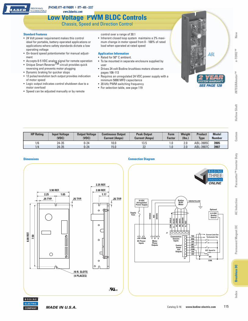
Low Voltage PWM BLDC ControlsChassis, Speed and Direction Control
ControlInputs
andOutputs
24 VDCUnregulated
Power Supply
SupplyFuse
+24V
0-5 VDCAnalogSource
PCOM C B A
ORA
NG
E
RED
BRO
WN
BodineBLDCMotor
COM
SH
IELD
H—
B
LACK
HC
GRE
EN
HB
W
HIT
E
HA
B
ROW
N
H+
RED
TAK
BRK
ENA
DIRLMT
COM
VRFVIN
Current Limit OutTachometer Out
EXT. Speed In
INT.
COM.J2
J1
Optional
DC PowerInputs
MotorPhase
Outputs
CommutationSensorsInputs
GREEN/YELLOW
HP Rating Input Voltage Output Voltage Continuous Output Peak Output Form Weight Product Model (VDC) (VDC) Current (Amps) Current (Amps) Factor (lbs.) Type Number
1/6 24-35 0-24 10.0 13.5 1.0 2.0 ABL-3905C 3905 1/4 24-35 0-24 15.0 22 1.0 2.0 ABL-3907C 3907
1.65
.25 TYP.
3.90 REF.
8.00
REF
.
2.25
7.50
.25 TYP. .25 TYP.
1.172.00 REF.
.10 R. SLOTS(4 PLACES)
2.25 REF.
control over a range of 30:1• Inherent closed loop system maintains a 2% maxi-
mum change in motor speed from 0 - 100% of rated load when operated at rated speed
Application Information• Rated for 50° C ambient.• To be mounted in separate enclosure supplied by
user• Drives 24 volt Bodine brushless motors shown on
pages 106-113• Requires an unregulated 24 VDC power supply with a
minimum 5000 MFD capacitance• 20 kHz PWM switching frequency• For selection table, see page 119
Standard Features• 24 Volt power requirement makes this control
ideal for portable, battery-operated applications or applications where safety standards dictate a low operating voltage
• On-board speed potentiometer for manual adjust-ment
• Accepts 0-5 VDC analog signal for remote operation• Unique Smart ReverseTM circuit provides quick
reversing and prevents motor plugging• Dynamic braking for quicker stops• 12 pulse/revolution tach output provides indication
of motor speed• Logic output indicates control shutdown due to a
motor overload• Speed can be adjusted manually or by remote
Dimensions Connection Diagram
ABL
THREEB O D I N E
DIMENSIONS
ONLINE

www.bodine-electric.com Catalog S-16 116
R
MADE IN U.S.A.
Filtered SCR BLDC ControlsChassis, Speed and Direction Control
Dimensions Connection Diagram
3.00
.25 TYP.
5.50 REF.
8.00
REF
.
1.25
7.50
TYP
ICA
L
.25 TYP. .25 TYP1.17
1.80 REF.
.10 R. SLOTS(6 PLACES)
1.25
2.63 REF.
HP Rating Input Voltage Output Voltage Continuous Output Peak Output Form Weight Product Model (VAC, 50/60 Hz) (VDC) Current (Amps) Current (Amps) Factor (lbs.) Type Number
3/8 @ 2500 rpm 115 0-130 3.0 6.0 1.0 2.5 ABL-3911C 3911 1/3 @ 10,000 rpm 115 0-130 3.0 6.0 1.0 2.5 ABL-3921C 3921
A B C
BRO
WN
RED
Optional model 3983cable may be used forcable connections
BODINEBLDCMOTOR
ORA
NG
E
H+
BRO
WN
WH
ITE
GRE
ENB
LACK
HA HB
HC H-
COM
CommutationSensorInputs
L N
AC PowerInputs
115
V60
Hz. YE
LLO
W
ORA
NG
E
BLU
E
S3 S2 S1
Speed PotConnections
10K Ohm SpeedPotentiometer
(Includedwith control)
MA
XM
INA
CCEL
DEC
ELTO
RQ
ControlInputs
DIR
DIR
COM
DIS
AB
LE
DIS
COM
DEC
ELD
ECEL
COM
DIR
ECTI
ON
Clos
ed=C
WO
pen=
CCW
DIS
AB
LECl
osed
=Bra
ke to
Sto
pO
pen=
Run
DEC
ELCl
osed
=Dec
el. t
o St
opO
pen=
Acc
el.
Optionaluser-supplied
switches }
RED
SHIE
LD
EarthGround
ChassisGroundScrew
MotorPhase
Outputs
User must supply wire for all external connections
Application Information• Rated for 50° C ambient • Intended to be mounted in separate enclosure
supplied by user• Drives 130 V brushless motors shown on page
106-113• Screw terminal block for line and motor
connections• Plug-in connector for commutation connections• .25" quick connect tabs for user interface
connections• Model 3911 for 2500 rpm motors. Model 3921 for
10,000 rpm motors• See page 120 for selection tables
Optional Accessories• Model 3983 cable connection assembly,
see page 122• Model 3982 cable extension, see page 122• Model 3984 analog interface and isolation module,
see page 122
Standard Features• Operates from 115 Volt AC line • Filtered DC output results in cooler operation of
the motor• Unique Smart ReverseTM circuit for remote control
of motor direction• Dynamic braking for quicker stops• 12 pulse/revolution tach output provides indication of
motor speed• Green LED indicates AC power on• Red LED indicates control shutdown due to a fault
condition• Speed can be adjusted manually with a remote 10K
ohm potentiometer (included)• DIP switches set the current limit so that the same
control model can drive any size Bodine motor• Five onboard user-adjustable pots for torque limit,
minimum speed limit, maximum speed limit, accel-eration time and deceleration time
• Fuseholders for line and motor fuses (fuses included)• Inherent closed loop system maintains a 1% maxi-
mum change in motor speed from 0 - 100% of rated load when operated at rated speed
ABL
THREEB O D I N E
DIMENSIONS
ONLINE

Catalog S-16 www.bodine-electric.com 117
R
MADE IN U.S.A.
In
dex
Bru
shle
ss D
C Pe
rman
ent M
agne
t DC
AC
Indu
ctio
n
Pace
sette
r™ In
vert
er D
uty
Cust
om
Hol
low
Sha
ft IN
TEG
RAm
otor
™
e-TO
RQ™
N
ew
Filtered SCR BLDC ControlsNEMA 12, Speed and Direction Control
6.16
8.44
72 REF. 72 REF.
To 115 VAC50/60Hz Line Optional Model 3982 Cable
for additional 72 inch extension
Bodine BLDCMotor
3.94
Speed
BrakeRev.Fwd.
Dimensions And Connections
HP Rating Input Voltage Output Voltage Continuous Output Peak Output Current Form Weight Product Model (VAC, 50/60 Hz) (VDC) Current (Amps) (Amps) Factor (lbs.) Type Number1
3/8 @ 2500 rpm 115 0-130 3.0 6.0 1.0 7.5 ABL-3912E 3912 1/3 @ 10,000 rpm 115 0-130 3.0 6.0 1.0 7.5 ABL-3913E N3913 1 NOTE: Model numbers shown in bold type are in stock. “N” model numbers require lead time and minimum quantities.
• Rotary switch on enclosure to select motor direction• Fuseholders for line and motor fuses (included)• AC line cable and motor cable factory-installed
Application Information• Rated for 40° C ambient • Drives 130 V brushless motors shown on pages
106-113• Two means of mounting: face mounting using self-
tapping screws on back surface, or fl ange mounting by installing four brackets (included)
• Model 3912 for 2500 rpm motors. Model 3913 for 10,000 rpm motors.
• For selection tables, see page 120
Optional Accessories• Model 3982 cable extension, see page 122• IP44 sealing kit model 0895 for protection against
splashing water, see page 122
Standard Features• Operates from 115 Volt AC line • Filtered DC output results in cooler operation of the
motor• Unique Smart ReverseTM circuit allows remote
control of motor direction• NEMA 12 enclosure for environmental protection• Dynamic braking for quicker stops• 12 pulse/revolution tach output provides indication
of motor speed• Red LED indicates control shutdown due to a fault
condition• Speed can be adjusted manually using potentiom-
eter on enclosure• DIP switches set the current limit so that the same
control model can drive any size Bodine motor• Inherent closed loop system maintains a 1% maxi-
mum change in motor speed from 0 - 100% of rated load when operated at rated speed
• Toggle switch on enclosure to turn AC power on/off• Lamp on enclosure indicates AC power on
ABL
THREEB O D I N E
DIMENSIONS
ONLINE

www.bodine-electric.com Catalog S-16 118
R
MADE IN U.S.A.
Unfi ltered SCR BLDC Controls Chassis, Speed and Direction Control
Dimensions Connection Diagram
3.00
.25 TYP.
5.50 REF.
8.00
REF
.
1.25
7.50
TYP
ICA
L
.25 TYP. .25 TYP1.17
1.80 REF.
.10 R. SLOTS(6 PLACES)
1.25
HP Rating Input Voltage Output Voltage Continuous Output Peak Output Current Form Weight Product Model (VAC, 50/60 Hz) (VDC) Current (Amps) (Amps) Factor (lbs.) Type Number
3/8 115 0-90 3.0 6.0 1.6 2.5 ABL-3910C 3910
Application Information• Rated for 50° C ambient • Intended to be mounted in separate enclosure sup-
plied by user• Drives 130 V brushless motors shown on pages
106-113• .25 inch quick connect tabs for line, motor connec-
tions, and user interface connections• Plug-in connector for commutation connections• For selection table, see page 121
Optional Accessories• Model 3983 cable connection assembly,
see page 122• Model 3982 cable extension, see page 122• Model 3984 analog interface and isolation module,
see page 122• Fuse and speed potentiometer kit (part number
433 00270), see page 122
Standard Features• Operates from 115 Volt AC line • Unique Smart ReverseTM circuit allows remote
control of motor direction• 12 pulse/revolution tach output provides indication of
motor speed• Green LED indicates AC power on• Red LED indicates control shutdown due to a fault
condition• Speed can be adjusted manually with a remote 10K
ohm potentiometer (not included)• DIP switches set the current limit so that the same
control model can drive any size Bodine motor• Inherent closed loop system maintains a 1% maxi-
mum change in motor speed from 0 - 100% of rated load when operated at rated speed
• Fuseholder for line and motor fuses (line fuse only included)
A B C
BRO
WN
RED
Optional model 3983cable may be used forcable connections
BODINEBLDCMOTOR
ORA
NG
E
H+
BRO
WN
WH
ITE
GRE
ENB
LACK
HA HB
HC H-
COM
CommutationSensorInputs
L N
AC PowerInputs
115
V60
Hz. YE
LLO
W
ORA
NG
E
BLU
E
S3 S2 S1
Speed PotConnections
10K Ohm SpeedPotentiometer
(Includedwith control)
MA
XM
INA
CCEL
DEC
ELTO
RQ
ControlInputs
DIR
DIR
COM
DIS
AB
LE
DIS
COM
DEC
ELD
ECEL
COM
DIR
ECTI
ON
Clos
ed=C
WO
pen=
CCW
DIS
AB
LECl
osed
=Bra
ke to
Sto
pO
pen=
Run
DEC
ELCl
osed
=Dec
el. t
o St
opO
pen=
Acc
el.
Optionaluser-supplied
switches }
RED
SHIE
LD
EarthGround
ChassisGroundScrew
MotorPhase
Outputs
user must supply wire for all external connections
ABL
THREEB O D I N E
DIMENSIONS
ONLINE

Catalog S-16 www.bodine-electric.com 119
R
MADE IN U.S.A.
In
dex
Bru
shle
ss D
C Pe
rman
ent M
agne
t DC
AC
Indu
ctio
n
Pace
sette
r™ In
vert
er D
uty
Cust
om
Hol
low
Sha
ft IN
TEG
RAm
otor
™
e-TO
RQ™
N
ew
Low Voltage Chassis BLDC ControlsType ABL Selection Table
SYSTEM PERFORMANCE WHEN USING BODINE 24V BLDC MOTORS WITH BODINE LOW VOLTAGE BLDC CONTROLS
Motor/Gearmotor Specifi cations Matching Control Model NumbersModel Number
Speed Continuous Accessory No Product Nameplate Reference Chassis Range Torque Shaft1 Accessory Type Rating Page
(rpm) (lb-in.) Shaft1 (HP) Motors Without Gear Reducers150 - 2500 1.6 – 3502 22B2BEBL 1/16 106 3905150 - 2500 3.1 3604 N3504 22B4BEBL 1/8 106 3905150 - 2500 5.1 3600 N3500 34B3BEBL 1/5 107 3907150 - 2500 6.3 – N3507 34B4BEBL 1/4 107 3907Parallel Shaft Gearmotors0.6 - 14 40 N3636 N3536 22B2BEBL-D4 1/16 108 39050.6 - 14 100 – N3563 22B2BEBL-Z4 1/16 109 39050.8 - 21 100 – N3564 22B2BEBL-Z4 1/16 109 39051.2 - 28 40 N3635 N3535 22B2BEBL-D4 1/16 108 39051.2 - 28 100 – N3562 22B2BEBL-Z4 1/16 109 39051.7 - 42 40 N3634 N3534 22B2BEBL-D3 1/16 108 39053.3 - 83 29 3629 N3529 22B2BEBL-D3 1/16 108 39055.6 - 139 17 N3628 N3528 22B2BEBL-D3 1/16 108 39058.3 - 208 12 N3627 N3527 22B2BEBL-D3 1/16 108 390517 - 417 5.8 N3626 N3526 22B2BEBL-D3 1/16 108 39051.7 - 42 95 3661 N3561 22B3BEBL-Z3 1/11 109 39053.3 - 83 52 N3660 N3560 22B3BEBL-Z3 1/11 109 39055.6 - 139 31 N3659 N3559 22B3BEBL-Z2 1/11 109 39058.3 - 208 20 N3658 N3558 22B3BEBL-Z2 1/11 109 390517 - 417 10 N3657 N3557 22B3BEBL-Z2 1/11 109 39050.3 - 8 1 75 N3647 N3547 34B3BEBL-W4 1/5 110 39050.3 - 8.3 310 – N3575 34B3BEBL-E4 1/5 111 39050.6 - 14 166 N3624 N3524 34B3BEBL-W4 1/5 110 39050.6 - 14 341 – N3574 34B3BEBL-E4 1/5 111 39051.0 - 26 154 N3656 N3556 34B3BEBL-W4 1/5 110 39051.5 - 38 143 N3617 N3517 34B3BEBL-W3 1/5 110 39053.3 - 84 65 N3653 N3553 34B3BEBL-W3 1/5 110 39054.9 - 122 46 N3652 N3552 34B3BEBL-W2 1/5 110 390511 - 266 21 N3623 N3523 34B3BEBL-W2 1/5 110 390518 - 456 12 3611 N3522 34B3BEBL-W2 1/5 110 39050.8 - 21 350 – N3573 34B4BEBL-E4 1/4 111 39071.7 - 42 270 N3685 3585 34B4BEBL-E3 1/4 111 39073 - 83 135 N3683 N3583 34B4BEBL-E3 1/4 111 39075 - 125 90 N3682 N3582 34B4BEBL-E3 1/4 111 390710 - 250 45 N3680 N3580 34B4BEBL-E2 1/4 111 390720 - 500 25 – N3579 34B4BEBL-E1 1/4 111 3907Right Angle Gearmotors1.7 - 42 37 N3665 3565 22B4BEBL-3N 1/8 112 39052.5 - 62 37 N3666 N3566 22B4BEBL-3N 1/8 112 39055 - 125 35 3667 N3567 22B4BEBL-3N 1/8 112 390510 - 250 22 N3668 N3568 22B4BEBL-3N 1/8 112 390520 - 500 11 N3669 N3569 22B4BEBL-3N 1/8 112 39052.5 - 62 74 – N3586 34B3BEBL-5N 1/5 113 39073.3 - 83 70 – N3587 34B3BEBL-5N 1/5 113 39075 - 125 67 – N3588 34B3BEBL-5N 1/5 113 390710 - 250 33 – N3589 34B3BEBL-5N 1/5 113 390720 - 500 18.6 – N3590 34B3BEBL-5N 1/5 113 39072.5 - 62 79 N3691 N3591 34B4BEBL-5N 1/4 113 39073.3 - 83 75 N3692 N3592 34B4BEBL-5N 1/4 113 39075 - 125 75 N3693 N3593 34B4BEBL-5N 1/4 113 390710 - 250 42 N3694 N3594 34B4BEBL-5N 1/4 113 390720 - 500 24 N3695 N3595 34B4BEBL-5N 1/4 113 3907
1 NOTE: Model numbers shown in bold type are in stock. “N” model numbers require lead time and minimum quantities.
NOTE: Some of the newer motors shown in this catalog do not yet appear in these tables. Refer to www.bodine-electric.com for the most up-to-date information.

www.bodine-electric.com Catalog S-16 120
R
MADE IN U.S.A.
Filtered Chassis BLDC ControlsType ABL Selection Table
SYSTEM PERFORMANCE WHEN USING BODINE 130V BLDC MOTORS WITH BODINE FILTERED BLDC CONTROLS (130 VDC OUTPUT)
Matching Control Model NumbersMotor/Gearmotor Specifi cations
Speed Cont. Accessory No Product Nameplate Reference Encased Chassis Range Torque Shaft1 Accessory Type Rating Page (rpm) (lb-in.) Shaft1 (HP) Motors Without Gear Reducers150 - 2500 1.6 – 3302 22B2BEBL 1/16 106 3912 3911150 - 2500 3.1 3404 3304 22B4BEBL 1/8 106 3912 3911100 - 2500 5.1 N3406 3306 34B3BEBL 1/5 107 3912 3911400 - 10,000 1.2 – 3314 22B4BEBL 1/5 106 N3913 3921100 - 2500 6.3 – N3307 34B4BEBL 1/4 107 3912 3911400 - 10,000 2.1 – 3317 34B4BEBL 1/3 107 N3913 3921100 - 2500 9.4 3409 3309 34B6BEBL 3/8 107 3912 3911Parallel Shaft Gearmotors0.6 - 14 40 N3433 3333 22B2BEBL–D4 1/16 108 3912 39110.8 - 21 100 – N3364 22B2BEBL-Z4 1/16 109 3912 39111.2 - 28 40 N3431 N3331 22B2BEBL-D4 1/16 108 3912 39111.7 - 42 40 N3430 N3330 22B2BEBL-D3 1/16 108 3912 39113 - 83 29 N3429 3329 22B2BEBL-D3 1/16 108 3912 39115.6 - 139 17 N3428 N3328 22B2BEBL-D3 1/16 108 3912 39118.3 - 208 12 N3427 3327 22B2BEBL-D3 1/16 108 3912 391117 - 417 5.8 N3426 3326 22B2BEBL-D3 1/16 108 3912 39110.6 - 14 100 N3463 3363 22B3BEBL-Z4 1/11 109 3912 39111.2 - 28 100 N3462 N3362 22B3BEBL-Z4 1/11 109 3912 39111.7 - 42 95 N3461 N3361 22B3BEBL-Z3 1/11 109 3912 39113 - 83 52 N3460 N3360 22B3BEBL-Z3 1/11 109 3912 39115.6 - 139 31 N3459 N3359 22B3BEBL-Z2 1/11 109 3912 39118.3 - 208 20 N3458 3358 22B3BEBL-Z2 1/11 109 3912 391117 - 417 10 N3457 3357 22B3BEBL-Z2 1/11 109 3912 39110.3 - 8 175 N3447 N3347 34B3BEBL-W4 1/5 110 3912 3911 0.3 - 8.3 310 – N3375 34B3BEBL-E4 1/5 111 3912 39110.6 - 14 341 – 3374 34B3BEBL-E4 1/5 111 3912 39110.6 - 14 166 N3446 3346 34B3BEBL-W4 1/5 110 3912 39110.8 - 21 350 – 3373 34B3BEBL-E4 1/5 111 3912 39111 - 26 154 N3456 N3356 34B3BEBL-W4 1/5 110 3912 39111.5 - 38 143 N3455 N3355 34B3BEBL-W3 1/5 110 3912 39113.3 - 84 65 N3453 3353 34B3BEBL-W3 1/5 110 3912 39114.9 - 122 46 N3452 3352 34B3BEBL-W2 1/5 110 3912 391111 - 266 21 N3450 N3350 34B3BEBL-W2 1/5 110 3912 391118 - 456 12 N3449 N3349 34B3BEBL-W2 1/5 110 3912 39111.7 - 42 270 N3485 3385 34B4BEBL-E3 1/4 111 3912 39113 - 83 135 3483 3383 34B4BEBL-E3 1/4 111 3912 39115 - 125 90 N3482 N3382 34B4BEBL-E3 1/4 111 3912 391110 - 250 45 N3480 3380 34B4BEBL-E2 1/4 111 3912 391120 - 500 25 – 3379 34B4BEPM-E1 1/4 111 3912 39113 - 83 245 – N3372 34B6BEBL-F3 3/8 111 3912 39115 - 125 163 – N3371 34B6BEBL-F3 3/8 111 3912 391110 - 250 82 N3470 N3370 34B6BEBL-F2 3/8 111 3912 391120 - 500 42 – 3369 34B6BEBL-F1 3/8 111 3912 3911 Right Angle Gearmotors1.7 - 42 37 N3421 N3321 22B4BEBL-3N 1/8 112 3912 39112.5 - 62 37 N3422 3322 22B4BEBL-3N 1/8 112 3912 39115 - 125 35 N3423 N3323 22B4BEBL-3N 1/8 112 3912 391110 - 250 22 3424 N3324 22B4BEBL-3N 1/8 112 3912 391120 - 500 11 N3425 3325 22B4BEBL-3N 1/8 112 3912 39112.5 - 62 74 – 3386 34B3BEBL-5N 1/5 113 3912 39113 - 83 70 – N3387 34B3BEBL-5N 1/5 113 3912 39115 - 125 59 – N3388 34B3BEBL-5N 1/5 113 3912 391110 - 250 33 – N3389 34B3BEBL-5N 1/5 113 3912 391120 - 500 18.6 – N3390 34B3BEBL-5N 1/5 113 3912 39112.5 - 62 79 N3491 N3391 34B4BEBL-5N 1/4 113 3912 39113 - 83 75 N3492 N3392 34B4BEBL-5N 1/4 113 3912 39115 - 125 75 3493 N3393 34B4BEBL-5N 1/4 113 3912 391110 - 250 42 N3494 N3394 34B4BEBL-5N 1/4 113 3912 391120 - 500 24 N3495 N3395 34B4BEBL-5N 1/4 113 3912 39112.5 - 62 109 – N3396 34B6BEBL-5N 3/8 113 3912 39113 - 83 104 – N3397 34B6BEBL-5N 3/8 113 3912 39115 - 125 98 – N3398 34B6BEBL-5N 3/8 113 3912 391110 - 250 64 – 3399 34B6BEBL-5N 3/8 113 3912 391120 - 500 36 – N3378 34B6BEBL-5N 3/8 113 3912 3911
Model Number
1 NOTE: Model numbers shown in bold type are in stock. “N” model numbers require lead time and minimum quantities.

Catalog S-16 www.bodine-electric.com 121
R
MADE IN U.S.A.
In
dex
Bru
shle
ss D
C Pe
rman
ent M
agne
t DC
AC
Indu
ctio
n
Pace
sette
r™ In
vert
er D
uty
Cust
om
Hol
low
Sha
ft IN
TEG
RAm
otor
™
e-TO
RQ™
N
ew
Unfi ltered Chassis BLDC Controls Type ABL Selection Table
SYSTEM PERFORMANCE WHEN USING BODINE 130V BLDC MOTORS WITH BODINE UNFILTERED BLDC CONTROLS (90 VDC OUTPUT)
Motor or Gearmotor Specifi cations Matching Control Model NumbersModel Number
1 NOTE: Model numbers shown in bold type are in stock. “N” model numbers require lead time and minimum quantities.
Speed Cont. Torque Accessory No Accessory Product Nameplate Reference Chassis Range (rpm) (lb-in.) Shaft1 Shaft Type Rating (HP) Page
Motors Without Gear Reducers 150 - 1725 1.1 – 3302 22B2BEBL 1/16 106 3910 150 - 1725 2.6 3404 3304 22B4BEBL 1/8 106 3910 100 - 1725 3.3 N3406 3306 34B3BEBL 1/5 107 3910 100 - 1725 4.1 – N3307 34B4BEBL 1/4 107 3910 100 - 1725 6.1 3409 3309 34B6BEBL 3/8 107 3910Parallel Shaft Gearmotors 0.6 - 9.6 40 N3433 3333 22B2BEBL-D4 1/16 108 3910 0.8 - 14 100 – N3364 22B2BEBL-Z4 1/16 109 3910 1.2 - 20 40 N3431 N3331 22B2BEBL-D4 1/16 108 3910 1.7 - 29 40 N3430 N3330 22B2BEBL-D3 1/16 108 3910 3 - 58 24 N3429 3329 22B2BEBL-D3 1/16 108 3910 5.6 - 96 15 N3428 N3328 22B2BEBL-D3 1/16 108 3910 8.3 - 144 9.8 N3427 3327 22B2BEBL-D3 1/16 108 3910 17 - 288 4.6 N3426 3326 22B2BEBL-D3 1/16 108 3910 0.6 - 9.6 100 N3463 3363 22B3BEBL-Z4 1/11 109 3910 1.2 - 20 100 N3462 N3362 22B3BEBL-Z4 1/11 109 3910 1.7 - 29 95 N3461 N3361 22B3BEBL-Z3 1/11 109 3910 3 - 58 38 N3460 N3360 22B3BEBL-Z3 1/11 109 3910 5.6 - 96 24 N3459 N3359 22B3BEBL-Z2 1/11 109 3910 8.3 - 144 16 N3458 3358 22B3BEBL-Z2 1/11 109 3910 17 - 288 8 N3457 3357 22B3BEBL-Z2 1/11 109 3910 0.3 - 5.6 175 N3447 N3347 34B3BEBL-W4 1/5 110 3910 0.3 - 5.8 310 – N3375 34B3BEBL-E4 1/5 111 3910 0.6 - 9.6 341 – 3374 34B3BEBL-E4 1/5 111 3910 0.6 - 9.6 166 N3446 3346 34B3BEBL-W4 1/5 110 3910 0.8 - 14 299 – 3373 34B3BEBL-E4 1/5 111 3910 1 - 18 154 N3456 N3356 34B3BEBL-W4 1/5 110 3910 1.5 - 26 143 N3455 N3355 34B3BEBL-W3 1/5 110 3910 3.3 - 58 64 N3453 3353 34B3BEBL-W3 1/5 110 3910 4.9 - 85 46 N3452 3352 34B3BEBL-W2 1/5 110 3910 11 - 184 21 N3450 N3350 34B3BEBL-W2 1/5 110 3910 18 - 315 12 N3449 N3349 34B3BEBL-W2 1/5 110 3910 1.7 - 29 199 N3485 3385 34B4BEBL-E3 1/4 111 3910 3 - 58 100 3483 3383 34B4BEBL-E3 1/4 111 3910 5 - 86 66 N3482 N3382 34B4BEBL-E3 1/4 111 3910 10 - 173 33 N3480 3380 34B4BEBL-E2 1/4 111 3910 20 - 345 17 – 3379 34B4BEPM-E1 1/4 111 3910 3 - 58 153 – N3372 34B6BEBL-F3 3/8 111 3910 5 - 86 102 – N3371 34B6BEBL-F3 3/8 111 3910 10 - 173 51 N3470 N3370 34B6BEBL-F2 3/8 111 3910 20 - 345 26 – 3369 34B6BEBL-F1 3/8 111 3910Right Angle Gearmotors 1.7 - 29 37 N3421 N3321 22B4BEBL-3N 1/8 112 3910 2.5 - 43 37 N3422 3322 22B4BEBL-3N 1/8 112 3910 5 - 86 35 N3423 N3323 22B4BEBL-3N 1/8 112 3910 10 - 173 20 3424 N3324 22B4BEBL-3N 1/8 112 3910 20 - 345 10 N3425 3325 22B4BEBL-3N 1/8 112 3910 2.5 - 43 46 – 3386 34B3BEBL-5N 1/5 113 3910 3 - 58 44 – N3387 34B3BEBL-5N 1/5 113 3910 5 - 86 37 – N3388 34B3BEBL-5N 1/5 113 3910 10 - 173 21 – N3389 34B3BEBL-5N 1/5 113 3910 20 - 345 11.6 – N3390 34B3BEBL-5N 1/5 113 3910 2.5 - 43 49 N3491 N3391 34B4BEBL-5N 1/4 113 3910 3 - 58 46 N3492 N3392 34B4BEBL-5N 1/4 113 3910 5 - 86 46 3493 N3393 34B4BEBL-5N 1/4 113 3910 10 - 173 26 N3494 N3394 34B4BEBL-5N 1/4 113 3910 20 - 345 14.8 N3495 N3395 34B4BEBL-5N 1/4 113 3910 2.5 - 43 52 – N3396 34B6BEBL-5N 3/8 113 3910 3 - 58 50 – N3397 34B6BEBL-5N 3/8 113 3910 5 - 86 52 – N3398 34B6BEBL-5N 3/8 113 3910 10 - 173 40 – 3399 34B6BEBL-5N 3/8 113 3910 20 - 345 23 – N3378 34B6BEBL-5N 3/8 113 3910
www.bodine-electric.com Catalog S-16 122
R
MADE IN U.S.A.
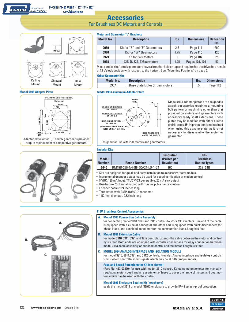
AccessoriesFor Brushless DC Motors and Controls
90°±2°
Model No. Description lbs. Dimensions Defl ection lbs. 0969 Kit for “E” and “F” Gearmotors 2.5 Page 111 200 0970 Kit for “W” Gearmotors 1.75 Page 110 125 0979 Kit for 34B Motors 1 Page 107 25 5968 22B-D, 22B-Z Gearmotors 1.25 Pages 108, 109 50
Motor and Gearmotor “L” Brackets
Most parallel shaft stock gearmotors have a breather hole on top and require that the driveshaft remain at 12 o‘clock position with respect to the horizon. See “Mounting Positions” on page 2.
C.
A.
115V Brushless Control Accessories
B.
Model 0993 adaptor plates are designed to attach accessories requiring a mounting bolt pattern or machining other than that provided on motors and gearmotors with accessory ready shaft extensions. These plates may be modifi ed with either a lathe or drill press. IP-44 protection is maintained when using this adaptor plate, as it is not necessary to disassemble the motor or gearmotor.
Model 0993 Aluminum Adaptor Plate
(2) #4-40 UNC-2B THRU ON 1.812 B.C.
(2) ADAPTOR PLATE MOUNTING HOLES ON 1.274 B.C. (REF.)
30°
45°
(2) #2-56 UNC-2B THRU ON .750 B.C.
(2) #8-32 UNC-2B THRUON 2.125 B.C.
.375 I.D.THRU .28
(BOSS PILOTS INTO MOTOR END SHIELD)
Model 0995 Adaptor Plate
Designed for use with 22B motors and gearmotors.
Encoder Kits
Resolution Fits Model (Pulses per Brushless Number Renco Number Revolution) Bodine Types 0940 RM15D-360-1/4-G6-5CA24-LD-1-C4 360 22B, 34B • Kits are designed for quick and easy installation to accessory ready models.
• Incremental encoder output may be used for speed verifi cation or motion control.• 5 VDC, 135 mA Input, TTL/CMOS compatible, 20 mA sink output• Quadrature, 2 channel output, with 1 index pulse per revolution• Encoder cable is 24 inches long.• Terminated with AMP 103650-7 connector.• 1.50 inch diameter, 0.82 inch long
3.0001.500
4.27 REF.
3.00
0
4.46
REF
.
.590REF.
1/4-20 UNC 2Bx.40 deep min.
(3 places)
A. Model 3983 Connection Cable Assembly for connecting model 3910, 3921 and 3911 controls to stock 130 V motors. One end of the cable
is equipped with a circular connector, the other end is equipped with quick disconnects for phase leads, and a molded connector for the commutation leads. Length: 6 feet.
B. Model 3982 Extension Cable for model 3910, 3911, 3921 and 3912 controls. Extends the cable between the motor and control
by six feet. Both ends are equipped with circular connections for easy connection between model 3983 cable assembly or encased control and the motor. Length: six feet.
C. MODEL 3984 ANALOG INTERFACE AND ISOLATION MODULE for model 3910, 3911,3921 and 3912 controls. Provides Analog interface and isolates controls
from system controller input signals which may be at different potentials.
Fuse and Speed Potentiometer Kit (not shown) (Part No. 433 00270) for use with model 3910 control. Contains potentiometer for manually
regulating motor speed and an assortment of fuses to cover the range of motors and gearmo-tors which can be used with the control.
Model 0895 Enclosure Sealing Kit (not shown) seals the model 3912 or model N3913 enclosure to provide IP-44 splash-proof protection.
Model No. Description lbs. Dimensions 0967 Base plate kit for 3F gearmotors .5 Page 112
Other Gearmotor KitsCeiling Mount
Sidewall Mount
BaseMount
Adaptor plate kit for E, F and W gearheads provides drop-in replacement of competitive gearmotors.