Brushless DC motor and driver package BX Series€¦ · HM-5069-4 Brushless DC motor and driver...
48
HM-5069-4 Brushless DC motor and driver package BX Series OPERATING MANUAL Thank you for purchasing an Oriental Motor product. This Operating Manual describes product handling procedures and safety precautions. • Please read it thoroughly to ensure safe operation. • Always keep the manual where it is readily available. Table of contents 1 Introduction ......................................... 2 1.1 Before use ............................................... 2 1.2 Overview of the product .......................... 2 1.3 Standards and CE Marking ..................... 2 1.4 System configuration ............................... 3 2 Safety precautions .............................. 4 3 Precautions for use ............................. 6 4 Preparation ......................................... 8 4.1 Checking the product .............................. 8 4.2 How to identify the product model ........... 9 4.3 Combination list ....................................... 9 4.4 Name and function of each part ............ 11 5 Installation......................................... 13 5.1 Location for installation.......................... 13 5.2 Installing the combination-type parallel-shaft gearhead.......................... 13 5.3 Installing the combination-type hollow-shaft flat gearhead ..................... 15 5.4 Installing the round-shaft type ............... 17 5.5 Installing the pinion-shaft type ............... 17 5.6 Installing a load on the combination-type parallel gearhead or round-shaft type ... 18 5.7 Installing a load on the combination-type hollow-shaft flat gearhead ..................... 19 5.8 Permissible overhung load and thrust load.............................................. 20 5.9 Installing the driver ................................ 22 5.10 Installing the regeneration unit .............. 23 5.11 Installing and wiring in compliance with EMC Directive........................................ 24 6 Connection ........................................ 27 6.1 Connecting to the power supply ............ 27 6.2 Turning on the power............................. 28 6.3 Connecting the regeneration unit .......... 28 6.4 Connecting the motor ............................ 29 6.5 Grounding the motor and driver ............ 29 6.6 Connecting input/output signal .............. 30 6.7 About input signal and output signal ..... 33 7 Running ............................................ 38 7.1 Rotating direction of the motor output shaft ....................................................... 38 7.2 Setting the running speed ..................... 39 8 Inspection ......................................... 42 8.1 Inspection items..................................... 42 9 Troubleshooting and remedial actions .............................................. 43 9.1 Troubleshooting ..................................... 43 9.2 Actions to be taken when the driver’s protection functions have activated ....... 44 10 Appendix ........................................... 45 10.1 Optional (Sold separately) ..................... 45 10.2 Recommended peripherals ................... 46
Transcript of Brushless DC motor and driver package BX Series€¦ · HM-5069-4 Brushless DC motor and driver...

HM-5069-4
Brushless DC motor and driver package BX Series OPERATING MANUAL
Thank you for purchasing an Oriental Motor product. This Operating Manual describes product handling procedures and safety precautions. • Please read it thoroughly to ensure safe operation. • Always keep the manual where it is readily available.
Table of contents 1 Introduction.........................................2
1.1 Before use ............................................... 2 1.2 Overview of the product .......................... 2 1.3 Standards and CE Marking ..................... 2 1.4 System configuration............................... 3
2 Safety precautions ..............................4 3 Precautions for use.............................6 4 Preparation .........................................8
4.1 Checking the product .............................. 8 4.2 How to identify the product model........... 9 4.3 Combination list....................................... 9 4.4 Name and function of each part ............ 11
5 Installation.........................................13 5.1 Location for installation.......................... 13 5.2 Installing the combination-type
parallel-shaft gearhead.......................... 13 5.3 Installing the combination-type
hollow-shaft flat gearhead ..................... 15 5.4 Installing the round-shaft type ............... 17 5.5 Installing the pinion-shaft type............... 17 5.6 Installing a load on the combination-type
parallel gearhead or round-shaft type ... 18 5.7 Installing a load on the combination-type
hollow-shaft flat gearhead ..................... 19 5.8 Permissible overhung load and
thrust load.............................................. 20 5.9 Installing the driver ................................ 22
5.10 Installing the regeneration unit .............. 23 5.11 Installing and wiring in compliance with
EMC Directive........................................ 24 6 Connection........................................27
6.1 Connecting to the power supply ............ 27 6.2 Turning on the power............................. 28 6.3 Connecting the regeneration unit .......... 28 6.4 Connecting the motor ............................ 29 6.5 Grounding the motor and driver ............ 29 6.6 Connecting input/output signal .............. 30 6.7 About input signal and output signal ..... 33
7 Running ............................................38 7.1 Rotating direction of the motor output
shaft ....................................................... 38 7.2 Setting the running speed ..................... 39
8 Inspection .........................................42 8.1 Inspection items..................................... 42
9 Troubleshooting and remedial actions ..............................................43 9.1 Troubleshooting..................................... 43 9.2 Actions to be taken when the driver’s
protection functions have activated....... 44 10 Appendix...........................................45
10.1 Optional (Sold separately)..................... 45 10.2 Recommended peripherals ................... 46
1 Introduction
− 2 −
1 Introduction
1.1 Before use Only qualified personnel should work with the product. Use the product correctly after thoroughly reading the section “Safety precautions.” The product described in this manual has been designed and manufactured for use in general industrial machinery, and must not be used for any other purpose. Oriental Motor Co., Ltd. is not responsible for any damage caused through failure to observe this warning.
1.2 Overview of the product The BX series is a brushless DC motor adopting a thin, high torque motor with encoder and high-precision driver. This product is available in two types; a combination type equipped with a special-purpose gearhead, which is best, suited to high-torque operation by gear speed reduction and a round shaft type which is the optimum for high speed requirements. You can extend the performance using the optional system upgrade tool (data setter OPX-1A).
1.3 Standards and CE Marking This product conforms with the EC’s Low Voltage Directive and EMC Directive under the following conditions. Take the following measures to ensure conformance with the EC’s Low Voltage Directive and EMC Directive.
For Low Voltage Directive This product is designed for use as a built-in component. • Install the product within an enclosure in order to avoid contact with the hands. • Be sure to maintain a protective earth in case the hands should make contact with the product. Securely
ground the Protective Earth Terminals of the motor and driver.
Motor Driver Applicable Standards EN 60034-1, EN 60034-5, EN 60664-1 EN 50178
Installation conditions
Motor is to be used as a component within other equipment. Overvoltage category: Ⅲ Pollution degree: 3 Protection against electric shock: Class Ⅰ equipment
Motor is to be used as a component within other equipment. Overvoltage category: Ⅲ Pollution degree: 2 Protection against electric shock: Class Ⅰ equipment
Protective range
IP54 (except for the shaft of the round shaft motor) IP10
Insulation class E −
EMC Directive This product has received EMC measures under the conditions specified in “Example of motor and driver installation and wiring” on page 26. Be sure to conduct EMC measures with the product assembled in your equipment by referring to 5.11, “Installing and wiring in compliance with EMC Directive” on page 24.

1 Introduction
− 3 −
UL/CSA Standards Certification Body Applicable Standards Standards File No.
30 W 60 W 120 W
UL 60950-1 CSA C22.2 No.60950-1 E208200
Motor∗ 200 W 400 W
UL UL 1004-1 CSA C22.2 No.100 E335369
Driver UL UL 508C CSA C22.2 No.14 E171462
∗ Insulation class of this motor is A.
UL RECOGNITION OF DRIVER Drivers are recognized by UL at following condition.
• Maximum Surrounding Air Temperature 50 °C. • Solid state motor overload protection is provided in each model. • Suitable For Use On A Circuit Capable Of Delivering Not More Than 5000 Arms Symmetrical Amperes,
120 or 240 VAC Maximum Voltage. • Integral solid state short circuit protection does not provide branch circuit protection. Branch circuit
protection must be provided in accordance with the National Electric Code and any additional local codes. • Use UL Listed Inverse Time Circuit Breaker rated 120 or 240 VAC, 15 A Only.
Hazardous substances RoHS (Directive 2002/95/EC 27Jan.2003) compliant
1.4 System configuration A sample system configuration using the BX series is provided below.
DriverMotor
External control equipmentConnect a programmable controller or other external control equipment you want to use to control the motor.
Mains filterUse an AC line filter to eliminate noise. It effectively reduces noise generated from the power source or driver.Power source
Make sure power supply voltage does not exceed the rated voltage.
External potentiometer PAVR-20KZ (supplied)Connect this unit to set the motor speed externally.
External DC voltageConnect an appropriate power supply to set the motor speed using DC voltage.
Circuit breaker or earth leakage breakerAlways connect a breaker to protect the primary circuit.
Or
Extensioncable(sold separately)
Extensioncable
Regeneration unit (sold separately)EPRC-400P, RGB100Connect this unit for vertical drive applications or operations involving an abrupt start/stop under a large inertial load.
Input/output signals
Operating data Data setterOPX-1A (sold separately)Connect this unit to set the functions you want to extend.
(sold separately)
• Three types of input power sources can be used: single-phase 100-115 V, single-phase 200-230 V and three-phase 200-230 V.
• The mechanical home seeking function requires home-position detection sensors.
2 Safety precautions
− 4 −
2 Safety precautions The precautions described below are intended to prevent danger or injury to the user and other personnel through safe, correct use of the product. Use the product only after carefully reading and fully understanding these instructions.
Warning Handling the product without observing the instructions that accompany a “Warning” symbol may result in serious injury or death.
Caution Handling the product without observing the instructions that accompany a “Caution” symbol may result in injury or property damage.
The items under this heading contain important handling instructions that the user should observe to ensure safe use of the product.
Warning
General • Do not use the product in explosive or corrosive environments, in the presence of flammable gases,
locations subjected to splashing water, or near combustibles. Doing so may result in fire, electric shock or injury.
• Assign qualified personnel the task of installing, wiring, operating/controlling, inspecting and troubleshooting the product. Failure to do so may result in fire, electric shock or injury.
• Do not transport, install the product, perform connections or inspections when the power is on. Always turn the power off before carrying out these operations. Failure to do so may result in electric shock.
• The terminals on the driver’s front panel marked with symbol indicate the presence of high voltage. Do not touch these terminals while the power is on to avoid the risk of fire or electric shock.
• The equipment provided with electromagnetic brake should be used when you want to utilize it for vertical application. If the motor has no electromagnetic brake, the holding force of the motor is insufficient when power is off, the movable parts may fall and cause injuries or damage of the equipment.
• Do not use the brake mechanism of the motor with electromagnetic brake as a safety brake. It is intended to hold the movable parts and motor position. This caution is to avoid personal injury or damage to the equipment.
• When the driver’s protection function is triggered, first remove the cause and then clear the protection function. Continuing the operation without removing the cause of the problem may cause malfunction of the motor, leading to injury or damage to equipment.
Installation • To prevent the risk of electric shock, use the motor and driver for class I equipment only. • Install the motor (gearhead) and driver in their enclosures in order to prevent electric shock or injury. • Install the motor and driver so as to avoid contact with hands, or ground them to prevent the risk of electric
shock.
Connection • Keep the driver’s input-power voltage within the specified range to avoid fire and electric shock. • Connect the cables securely according to the wiring diagram in order to prevent fire and electric shock. • Do not forcibly bend, pull or pinch the cable. Doing so may fire and electric shock. • To prevent electric shock, be sure to install the terminal cover (supplied) over the driver’s power supply
terminals after making connections.
Operation • Turn off the driver power in the event of a power failure, or the motor may suddenly start when the power
is restored and may cause injury or damage to equipment. • Do not turn ON the FREE input when the position is held in the vertical direction. Otherwise, the holding
force of the motor and electromagnetic brake will be lost, causing personal injury and equipment damage.
2 Safety precautions
− 5 −
Maintenance and inspection • Do not touch the connection terminals of the driver immediately after the power is turned off (for a period
of 30 seconds). The residual voltage may cause electric shock.
Repair, disassembly and modification • Do not disassemble or modify the motor (gearhead) or driver. This may cause electric shock or injury.
Refer all such internal inspections and repairs to the branch or sales office from which you purchased the product.
Caution
General • Do not use the motor (gearhead), driver and the regeneration unit beyond their specifications, or electric
shock, injury or damage to equipment may result. • Keep your fingers and objects out of the openings in the motor and driver. Failure to do so may result in
fire, electric shock or injury. • During running and for some time after stopping the equipment, do not touch the motor, driver and the
regeneration unit. You may be burnt by high temperature on the surfaces of the motor, driver and the regeneration unit.
Transportation • Do not hold the motor (gearhead) output shaft or motor cable. This may cause injury.
Installation • Keep the area around the motor and driver free of combustible materials in order to prevent fire or a skin
burn(s). • To prevent the risk of damage to equipment, leave nothing around the motor and driver that would obstruct
ventilation. • The motor and driver should be firmly secured on the metallic plate in order to prevent personal injury and
damage to the equipment. • The rotating part (output shaft) of the motor (gearhead) should be provided with a cover. Otherwise, injury
may occur. • Do not allow your finger to be caught between the equipment and motor or gearhead when installing the
motor with or without gearhead on the equipment. Otherwise, injury may occur.
Operation • Use the motor and driver in it‘s specified combination. This is to prevent fire. • Provide an emergency-stop device or emergency-stop circuit external to the equipment so that the entire
equipment will operate safely in the event of a system failure or malfunction. Failure to do so may result in injury.
• To prevent bodily injury, do not touch the rotating parts (output shaft) of the motor during operation. • Immediately when trouble has occurred, stop running and turn off the driver power. Failure to do so may
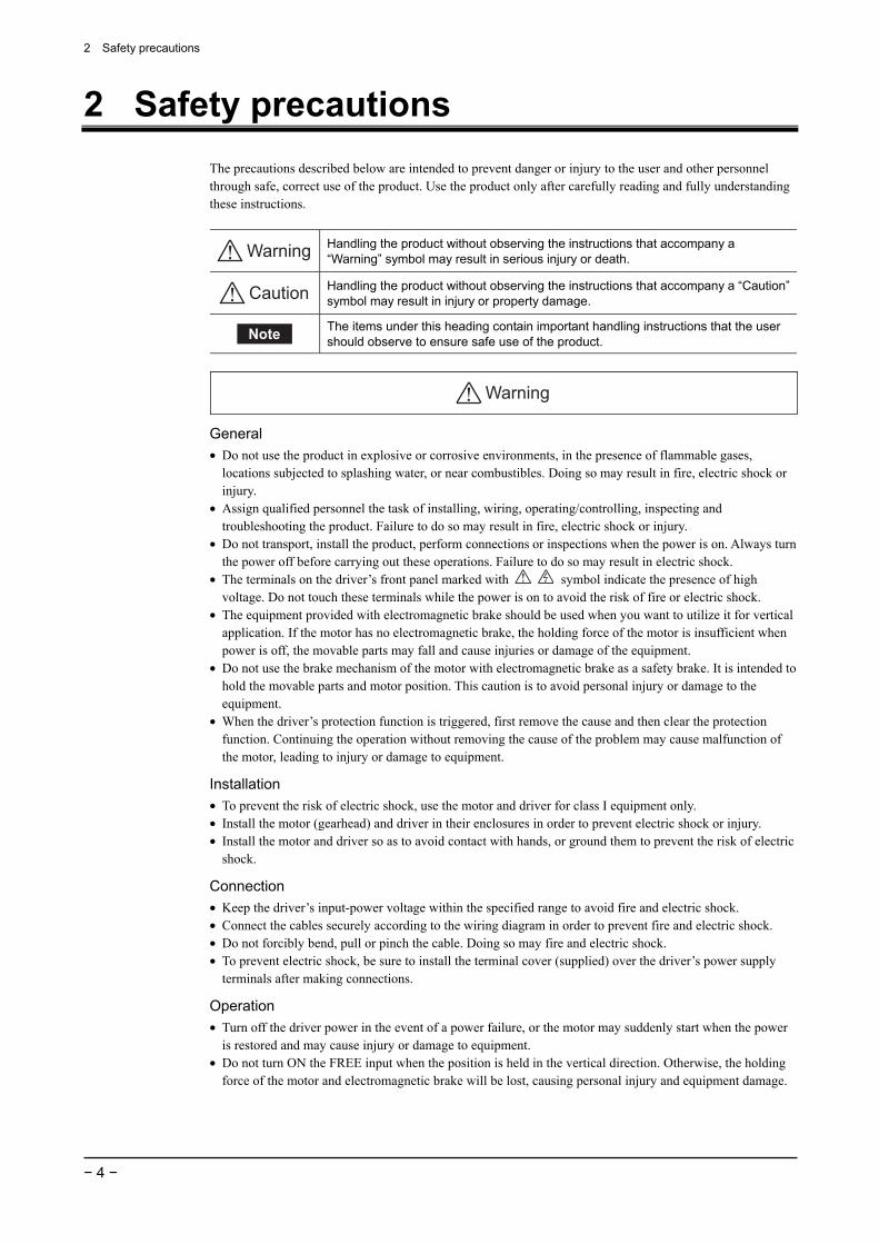
result in fire, electric shock or injury. • To prevent electric shock, use only an insulated screwdriver to adjust the internal switches. • The motor’s surface temperature may exceed 70 °C (158 °F), even under normal
operating conditions. If a motor is accessible during operation, post a warning label shown in the figure in a conspicuous position to prevent the risk of skin burn(s).
Warning label
Maintenance and inspection • To prevent the risk of electric shock, do not touch the terminals while measuring the insulation resistance or
conducting a voltage-resistance test.
Disposal • To dispose of the motor (gearhead) or driver, disassemble it into parts and components as much as possible
and dispose of individual parts/components as industrial waste.
3 Precautions for use
− 6 −
3 Precautions for use This section covers limitations and requirements the user should consider when using the BX series.
Connect protective devices to the power line Connect a circuit breaker or earth leakage breaker to the driver’s power line to protect the primary circuit. If an earth leakage breaker is to be installed, use one incorporating high-frequency noise elimination measures. Refer to 10.2, “Recommended peripherals” on page 46 for the selection of appropriate protective devices.
Use an electromagnetic brake motor for an application involving up/down travel. When the motor is used in an application involving up/down travel, use an electromagnetic brake motor to hold the load in position. To hold the load in position, apply the electromagnetic brake only after the motor has stopped. Do not use the brake to bring the moving motor to a halt. Repeated braking for such a purpose will wear the brake hub excessively, causing its holding ability to drop. Since the electromagnetic brake is of the non-excitation type, it can also be used to hold the load in position upon the occurrence of a power failure. However, this is not a secure means of holding the load. Do not use the electromagnetic brake as a safety brake.
Use a regeneration unit (sold separately) for vertical drive applications and those involving high inertial loads. The driver may be damaged if the energy that is regenerated during a vertical (gravitational) operation or due to an abrupt start/stop involving a large inertial load exceeds the maximum level that can be absorbed by the driver. The optional regeneration unit (sold separately) is designed to discharge the regenerated energy, thereby protecting the driver.
Do not use a solid-state relay (SSR) to turn on/off the power A circuit that turns on/off the power via a solid-state relay (SSR) may damage the motor and driver.
Conduct the insulation resistance measurement or withstand voltage test separately on the motor and the driver. Conducting the insulation resistance measurement or withstand voltage test with the motor and driver connected may result in injury or damage to equipment.
Do not conduct insulation resistance test or withstand voltage test on the encoder. These tests may damage the encoder.
Grease measures On rare occasions, a small amount of grease may ooze out from the geared motor. If there is concern over possible environmental damage resulting from the leakage of grease, check for grease stains during regular inspections. Alternatively, install an oil pen or other device to prevent leakage from causing further damage. Oil leakage may lead to problems in the customer’s equipment or products.
Apply grease on the hollow-shaft flat gearhead output shaft If you are using a hollow-shaft flat gearhead, apply grease (molybdenum disulfide grease, etc.) on the surface of the load shaft and inner walls of the hollow output shaft to prevent seizure.
3 Precautions for use
− 7 −
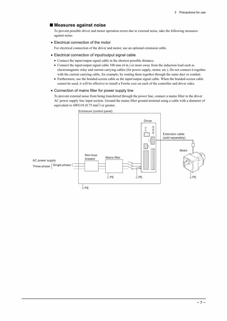
Measures against noise To prevent possible driver and motor operation errors due to external noise, take the following measures against noise:
• Electrical connection of the motor For electrical connection of the driver and motor, use an optional extension cable.
• Electrical connection of input/output signal cable • Connect the input/output signal cable in the shortest possible distance. • Connect the input/output signal cable 100 mm (4 in.) or more away from the induction load such as
electromagnetic relay and current carrying cables (for power supply, motor, etc.). Do not connect it together with the current carrying cable, for example, by routing them together through the same duct or conduit.
• Furthermore, use the braided-screen cable as the input/output signal cable. When the braided-screen cable cannot be used, it will be effective to install a Ferrite core on each of the controller and driver sides.
• Connection of mains filter for power supply line To prevent external noise from being transferred through the power line, connect a mains filter to the driver AC power supply line input section. Ground the mains filter ground terminal using a cable with a diameter of equivalent to AWG18 (0.75 mm2) or greater.
Driver
Extension cable(sold separately)
Motor
Mains filter
PE PE PE
PE
Non-fusebreaker
Enclosure (control panel)
AC power supplySingle-phaseThree-phase
4 Preparation
− 8 −
4 Preparation This section covers the points to be checked along with the names and functions of respective parts.
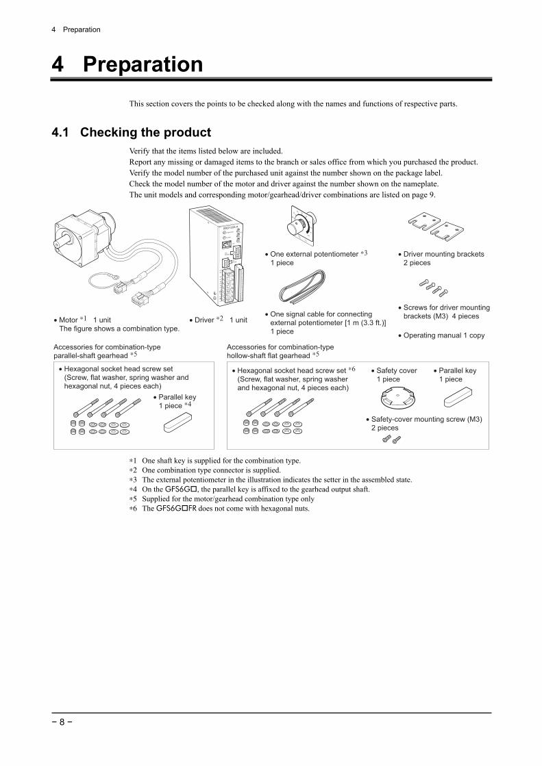
4.1 Checking the product Verify that the items listed below are included. Report any missing or damaged items to the branch or sales office from which you purchased the product. Verify the model number of the purchased unit against the number shown on the package label. Check the model number of the motor and driver against the number shown on the nameplate. The unit models and corresponding motor/gearhead/driver combinations are listed on page 9.
Accessories for combination-type parallel-shaft gearhead ∗5
Accessories for combination-type hollow-shaft flat gearhead ∗5
• Operating manual 1 copy
• Hexagonal socket head screw set(Screw, flat washer, spring washer and hexagonal nut, 4 pieces each)
• Parallel key1 piece
• Parallel key1 piece ∗4
• Safety cover1 piece
• Safety-cover mounting screw (M3)2 pieces
• Hexagonal socket head screw set ∗6(Screw, flat washer, spring washer and hexagonal nut, 4 pieces each)
• Motor ∗1 1 unitThe figure shows a combination type.
• Driver ∗2 1 unit
• Driver mounting brackets2 pieces
• Screws for driver mountingbrackets (M3) 4 pieces• One signal cable for connecting
external potentiometer [1 m (3.3 ft.)]1 piece
• One external potentiometer ∗31 piece
∗1 One shaft key is supplied for the combination type. ∗2 One combination type connector is supplied. ∗3 The external potentiometer in the illustration indicates the setter in the assembled state. ∗4 On the GFS6G , the parallel key is affixed to the gearhead output shaft. ∗5 Supplied for the motor/gearhead combination type only ∗6 The GFS6G FR does not come with hexagonal nuts.

4 Preparation
− 9 −
4.2 How to identify the product model
Series name BX series
Power input A: Single-phase 100-115 V C: Single-phase 200-230 V / Three-phase 200-230 V S: Three-phase 200-230 V
BX 5 120 A M - 5 SType of gearhead (combination type) S : Parallel-shaft gearhead FR : Hollow-shaft flat gearhead
Motor type M : With electromagnetic brake None : Standard type
Output power 30: 30 W 60: 60 W 120: 120 W 200: 200 W 400: 400 W
Motor size 2: 60 mm (2.36 in.) square 4: 80 mm (3.15 in.) square 5: 90 mm (3.54 in.) square 6: 104 mm (4.09 in.) square
Gear ratio/shaft shape Number : Gear ratio (combination type) A : Round-shaft type GFS : Pinion-shaft type
4.3 Combination list
Combination-type parallel-shaft gearhead The motor comes preassembled with a parallel-shaft gearhead.
• Standard • With electromagnetic brake
Unit model Motor model Gearhead model
Driver model Unit model Motor model Gearhead
model Driver model
BX230A- S BXD30A-A BX230AM- S BXD30A-A
BX230C- S BXM230-GFS GFS2G
BXD30A-C BX230CM- SBXM230M-GFS GFS2G
BXD30A-C
BX460A- S BXD60A-A BX460AM- S BXD60A-A
BX460C- S BXM460-GFS GFS4G
BXD60A-C BX460CM- SBXM460M-GFS GFS4G
BXD60A-C
BX5120A- S BXD120A-A BX5120AM- S BXD120A-A
BX5120C- S BXM5120-GFS GFS5G
BXD120A-C BX5120CM- SBXM5120M-GFS GFS5G
BXD120A-C
BX6200A- S BXD200A-A BX6200AM- S BXD200A-A
BX6200C- S BXM6200-GFS GFS6G
BXD200A-C BX6200CM- SBXM6200M-GFS GFS6G
BXD200A-C
BX6400S- S BXM6400-GFS GFS6G BXD400A-S BX6400SM- S BXM6400M-GFS GFS6G BXD400A-S
in the model names indicates a number representing the gear ratio (5, 10, 15, 20, 30, 50, 100 or 200).
Combination-type hollow-shaft flat gearhead The motor comes preassembled with a hollow-shaft flat gearhead.
• Standard • With electromagnetic brake
Unit model Motor model Gearhead model
Driver model Unit model Motor model Gearhead
model Driver model
BX230A- FR BXD30A-A BX230AM- FR BXD30A-A
BX230C- FR BXM230-GFS GFS2G FR
BXD30A-C BX230CM- FRBXM230M-GFS GFS2G FR
BXD30A-C
BX460A- FR BXD60A-A BX460AM- FR BXD60A-A
BX460C- FR BXM460-GFS GFS4G FR
BXD60A-C BX460CM- FRBXM460M-GFS GFS4G FR
BXD60A-C
BX5120A- FR BXD120A-A BX5120AM- FR BXD120A-A
BX5120C- FR BXM5120-GFS GFS5G FR
BXD120A-C BX5120CM- FRBXM5120M-GFS GFS5G FR
BXD120A-C
BX6200A- FR BXD200A-A BX6200AM- FR BXD200A-A
BX6200C- FR BXM6200-GFS GFS6G FR
BXD200A-C BX6200CM- FRBXM6200M-GFS GFS6G FR
BXD200A-C
BX6400S- FR BXM6400-GFS GFS6G FR BXD400A-S BX6400SM- FR BXM6400M-GFS GFS6G FR BXD400A-S
in the model names indicates a number representing the gear ratio (5, 10, 15, 20, 30, 50, 100 or 200).

4 Preparation
− 10 −
Round-shaft type
• Standard • With electromagnetic brake Unit model Motor model Driver model Unit model Motor model Driver model BX230A-A BXD30A-A BX230AM-A BXD30A-A
BX230C-A BXM230-A2
BXD30A-C BX230CM-A BXM230M-A2
BXD30A-C
BX460A-A BXD60A-A BX460AM-A BXD60A-A
BX460C-A BXM460-A2
BXD60A-C BX460CM-A BXM460M-A2
BXD60A-C
BX5120A-A BXD120A-A BX5120AM-A BXD120A-A
BX5120C-A BXM5120-A2
BXD120A-C BX5120CM-A BXM5120M-A2
BXD120A-C
BX6200A-A BXD200A-A BX6200AM-A BXD200A-A
BX6200C-A BXM6200-A
BXD200A-C BX6200CM-A BXM6200M-A
BXD200A-C
BX6400S-A BXM6400-A BXD400A-S BX6400SM-A BXM6400M-A BXD400A-S
Pinion-shaft type
• Standard • With electromagnetic brake Unit model Motor model Driver model Unit model Motor model Driver model
BX230A-GFS BXD30A-A BX230AM-GFS BXD30A-A
BX230C-GFS BXM230-GFS
BXD30A-C BX230CM-GFS BXM230M-GFS
BXD30A-C
BX460A-GFS BXD60A-A BX460AM-GFS BXD60A-A
BX460C-GFS BXM460-GFS
BXD60A-C BX460CM-GFS BXM460M-GFS
BXD60A-C
BX5120A-GFS BXD120A-A BX5120AM-GFS BXD120A-A
BX5120C-GFS BXM5120-GFS
BXD120A-C BX5120CM-GFSBXM5120M-GFS
BXD120A-C
BX6200A-GFS BXD200A-A BX6200AM-GFS BXD200A-A
BX6200C-GFS BXM6200-GFS
BXD200A-C BX6200CM-GFSBXM6200M-GFS
BXD200A-C
BX6400S-GFS BXM6400-GFS BXD400A-S BX6400SM-GFS BXM6400M-GFS BXD400A-S
4 Preparation
− 11 −
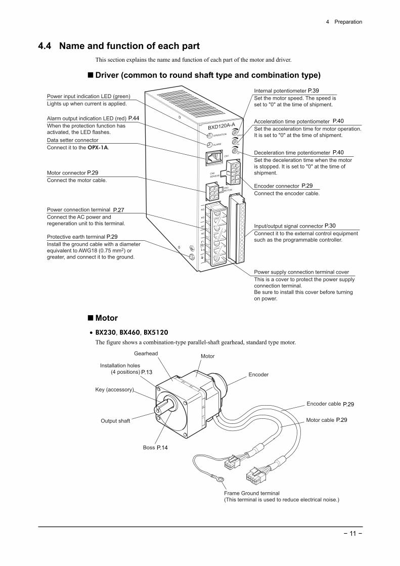
4.4 Name and function of each part This section explains the name and function of each part of the motor and driver.
Driver (common to round shaft type and combination type)
Power input indication LED (green)Lights up when current is applied.
Alarm output indication LED (red)When the protection function has activated, the LED flashes.
Encoder connectorConnect the encoder cable.
Motor connectorConnect the motor cable.
Power connection terminalConnect the AC power and regeneration unit to this terminal.
Protective earth terminalInstall the ground cable with a diameterequivalent to AWG18 (0.75 mm2) or greater, and connect it to the ground.
Internal potentiometerSet the motor speed. The speed is set to "0" at the time of shipment.
Acceleration time potentiometerSet the acceleration time for motor operation.It is set to "0" at the time of shipment.
Deceleration time potentiometerSet the deceleration time when the motor is stopped. It is set to "0" at the time ofshipment.
Data setter connectorConnect it to the OPX-1A.
Power supply connection terminal coverThis is a cover to protect the power supplyconnection terminal.Be sure to install this cover before turningon power.
Input/output signal connectorConnect it to the external control equipmentsuch as the programmable controller.
Motor
• BX230, BX460, BX5120 The figure shows a combination-type parallel-shaft gearhead, standard type motor.
MotorGearhead
Boss
Installation holes (4 positions)
Key (accessory)
Output shaft
Encoder
Encoder cable
Motor cable
Frame Ground terminal(This terminal is used to reduce electrical noise.)
P.44
P.29
P.27
P.29
P.39
P.40
P.40
P.29
P.30
P.14
P.13
P.29
P.29
4 Preparation
− 12 −
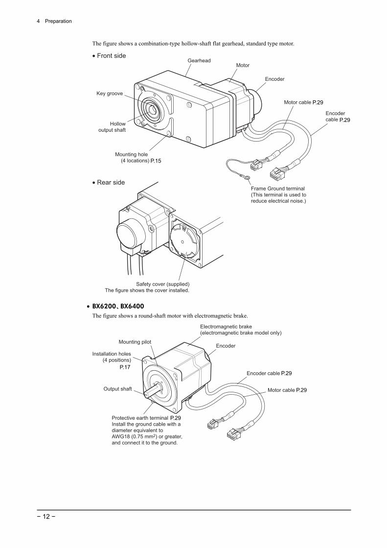
The figure shows a combination-type hollow-shaft flat gearhead, standard type motor.
• Front side
• Rear side
MotorGearhead
Hollowoutput shaft
Mounting hole (4 locations)
Key groove
Safety cover (supplied)The figure shows the cover installed.
Motor cable
Encoder
Encoder cable
Frame Ground terminal(This terminal is used to reduce electrical noise.)
• BX6200、BX6400 The figure shows a round-shaft motor with electromagnetic brake.
Electromagnetic brake (electromagnetic brake model only)
Encoder
Encoder cable
Motor cable
Mounting pilot
Installation holes (4 positions)
Output shaft
Protective earth terminalInstall the ground cable with a diameter equivalent toAWG18 (0.75 mm2) or greater, and connect it to the ground.
P.29
P.29
P.29
P.29
P.15
P.17
P.29
5 Installation
− 13 −
5 Installation This chapter explains the installation location and installation methods of the motor and driver, as well as how to install a load. Read the applicable sections carefully to install each item correctly.
Combination-type parallel-shaft gearhead See page 13, 18 Combination-type hollow-shaft flat gearhead See page 15, 19 Round-shaft type See page 17, 18
Pinion-shaft type Parallel-shaft gearhead: See page 13, 18 Hollow-shaft flat gearhead: See page 15, 19
5.1 Location for installation The motor and driver are designed and manufactured for installation in equipment. Install them in a well-ventilated location that provides easy access for inspection. The location must also satisfy the following conditions:
• Inside an enclosure that is installed indoors (provide vent holes) • Operating ambient temperature: 0 to +50 °C (+32 to +122 °F) (non-freezing) • Operating ambient humidity 85% or less (non-condensing) • Area that is free of explosive atmosphere or toxic gas (such as sulfuric gas) or liquid • Area not exposed to direct sun • Area free of excessive amount of dust, iron particles or the like • Area not subject to splashing water (rain, water droplets), oil (oil droplets) or other liquids • Area free of excessive salt • Area not subject to continuous vibration or excessive shocks • Area free of excessive electromagnetic noise (from welders, power machinery, etc.) • Area free of radioactive materials, magnetic fields or vacuum
Install the motor to a flat mounting plate offering excellent vibration resistance and high heat conductivity.
5.2 Installing the combination-type parallel-shaft gearhead
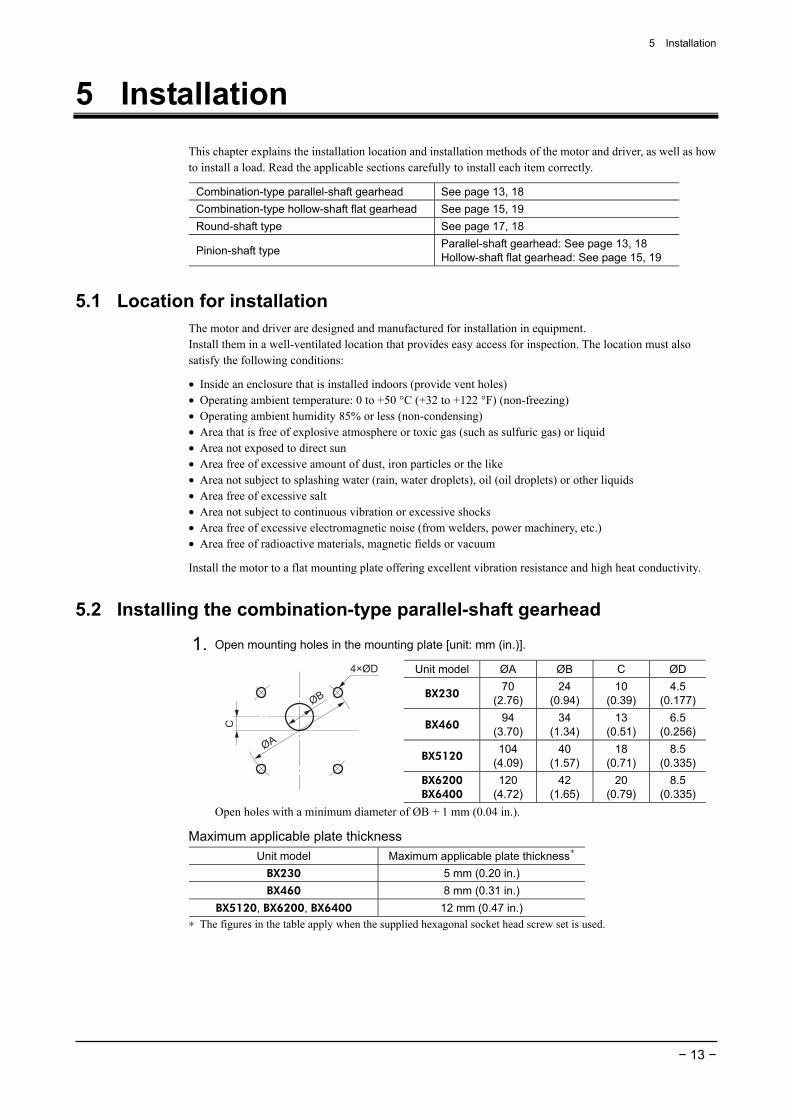
1. Open mounting holes in the mounting plate [unit: mm (in.)].
Unit model ØA ØB C ØD
BX230 70
(2.76) 24
(0.94) 10
(0.39) 4.5
(0.177)
BX460 94
(3.70) 34
(1.34) 13
(0.51) 6.5
(0.256)
BX5120 104
(4.09) 40
(1.57) 18
(0.71) 8.5
(0.335)
ØB
C
4×ØD
ØA
BX6200 BX6400
120 (4.72)
42 (1.65)
20 (0.79)
8.5 (0.335)
Open holes with a minimum diameter of ØB + 1 mm (0.04 in.).
Maximum applicable plate thickness Unit model Maximum applicable plate thickness∗
BX230 5 mm (0.20 in.) BX460 8 mm (0.31 in.)
BX5120, BX6200, BX6400 12 mm (0.47 in.) ∗ The figures in the table apply when the supplied hexagonal socket head screw set is used.
5 Installation
− 14 −
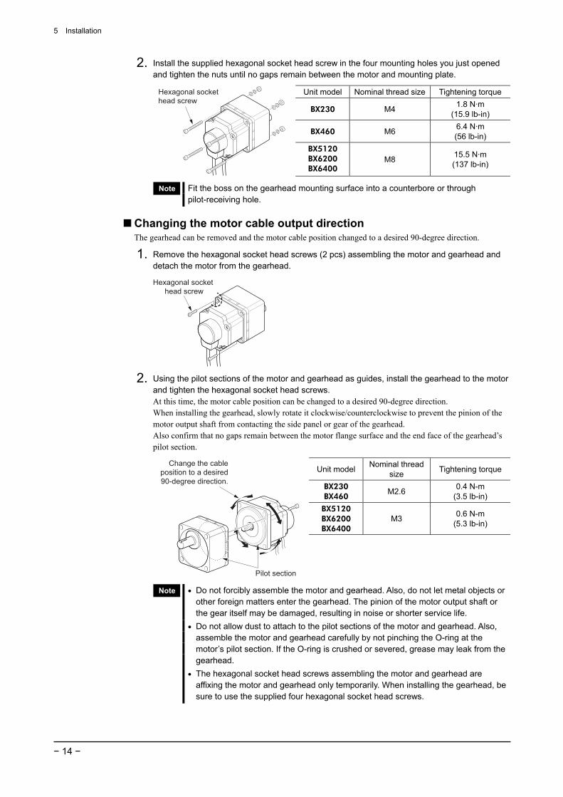
2. Install the supplied hexagonal socket head screw in the four mounting holes you just opened and tighten the nuts until no gaps remain between the motor and mounting plate.
Unit model Nominal thread size Tightening torque
BX230 M4 1.8 N·m (15.9 lb-in)
BX460 M6 6.4 N·m (56 lb-in)
Hexagonal socket head screw
BX5120 BX6200 BX6400
M8 15.5 N·m (137 lb-in)
Note Fit the boss on the gearhead mounting surface into a counterbore or through pilot-receiving hole.
Changing the motor cable output direction The gearhead can be removed and the motor cable position changed to a desired 90-degree direction.
1. Remove the hexagonal socket head screws (2 pcs) assembling the motor and gearhead and detach the motor from the gearhead.
Hexagonal socket head screw
2. Using the pilot sections of the motor and gearhead as guides, install the gearhead to the motor and tighten the hexagonal socket head screws. At this time, the motor cable position can be changed to a desired 90-degree direction. When installing the gearhead, slowly rotate it clockwise/counterclockwise to prevent the pinion of the motor output shaft from contacting the side panel or gear of the gearhead. Also confirm that no gaps remain between the motor flange surface and the end face of the gearhead’s pilot section.
Unit model Nominal thread size Tightening torque
BX230 BX460
M2.6 0.4 N-m (3.5 lb-in)
BX5120 BX6200 BX6400
M3 0.6 N-m (5.3 lb-in)
Pilot section
Change the cable position to a desired 90-degree direction.
Note • Do not forcibly assemble the motor and gearhead. Also, do not let metal objects or other foreign matters enter the gearhead. The pinion of the motor output shaft or the gear itself may be damaged, resulting in noise or shorter service life.
• Do not allow dust to attach to the pilot sections of the motor and gearhead. Also, assemble the motor and gearhead carefully by not pinching the O-ring at the motor’s pilot section. If the O-ring is crushed or severed, grease may leak from the gearhead.
• The hexagonal socket head screws assembling the motor and gearhead are affixing the motor and gearhead only temporarily. When installing the gearhead, be sure to use the supplied four hexagonal socket head screws.
5 Installation
− 15 −
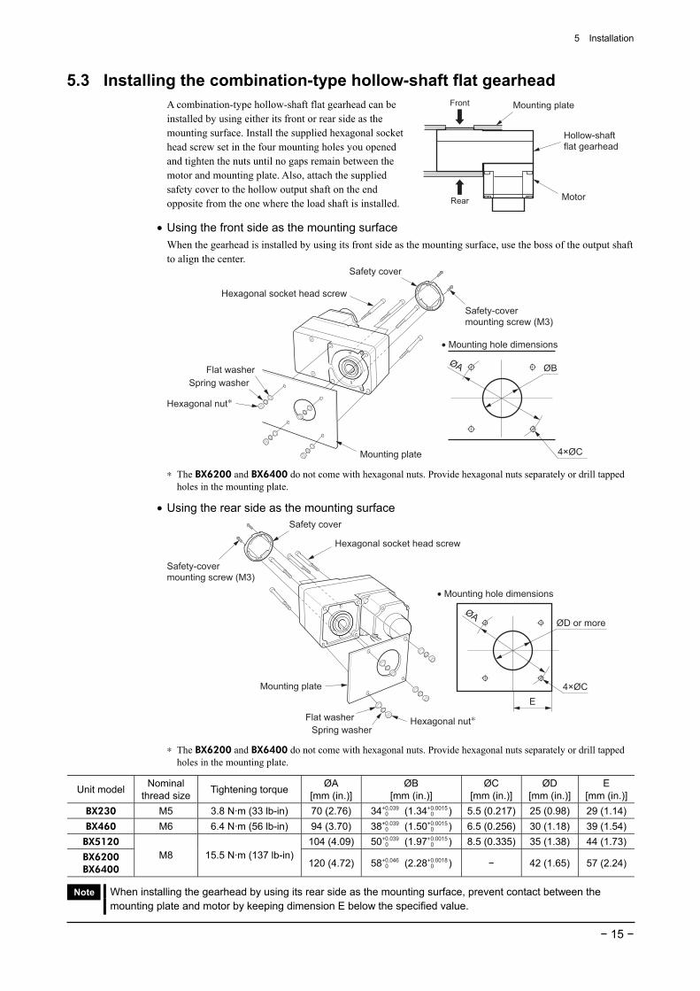
5.3 Installing the combination-type hollow-shaft flat gearhead A combination-type hollow-shaft flat gearhead can be installed by using either its front or rear side as the mounting surface. Install the supplied hexagonal socket head screw set in the four mounting holes you opened and tighten the nuts until no gaps remain between the motor and mounting plate. Also, attach the supplied safety cover to the hollow output shaft on the end opposite from the one where the load shaft is installed.
Front Mounting plate
Hollow-shaft flat gearhead
MotorRear
• Using the front side as the mounting surface When the gearhead is installed by using its front side as the mounting surface, use the boss of the output shaft to align the center.
Safety cover
Safety-cover mounting screw (M3)
Hexagonal socket head screw
Mounting plate
Flat washerSpring washer
Hexagonal nut∗
ØB
• Mounting hole dimensions
4×ØC
ØA
∗ The BX6200 and BX6400 do not come with hexagonal nuts. Provide hexagonal nuts separately or drill tapped holes in the mounting plate.
• Using the rear side as the mounting surface
Safety cover
Safety-cover mounting screw (M3)
Hexagonal socket head screw
Flat washer Hexagonal nut∗
Mounting plate
Spring washer
• Mounting hole dimensions
E4×ØC
ØD or moreØA
∗ The BX6200 and BX6400 do not come with hexagonal nuts. Provide hexagonal nuts separately or drill tapped holes in the mounting plate.
Unit model Nominal thread size Tightening torque ØA
[mm (in.)]ØB
[mm (in.)] ØC
[mm (in.)] ØD
[mm (in.)] E
[mm (in.)]BX230 M5 3.8 N·m (33 lb-in) 70 (2.76) 34+0.039
0 (1.34+0.0015 0 ) 5.5 (0.217) 25 (0.98) 29 (1.14)
BX460 M6 6.4 N·m (56 lb-in) 94 (3.70) 38+0.039 0 (1.50+0.0015
0 ) 6.5 (0.256) 30 (1.18) 39 (1.54)BX5120 104 (4.09) 50+0.039
0 (1.97+0.0015 0 ) 8.5 (0.335) 35 (1.38) 44 (1.73)
BX6200 BX6400
M8 15.5 N·m (137 lb-in)120 (4.72) 58+0.046
0 (2.28+0.0018 0 ) − 42 (1.65) 57 (2.24)
Note When installing the gearhead by using its rear side as the mounting surface, prevent contact between the mounting plate and motor by keeping dimension E below the specified value.
5 Installation
− 16 −
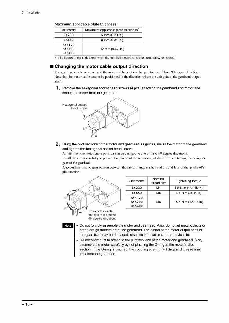
Maximum applicable plate thickness Unit model Maximum applicable plate thickness∗
BX230 5 mm (0.20 in.) BX460 8 mm (0.31 in.)
BX5120 BX6200 BX6400
12 mm (0.47 in.)
∗ The figures in the table apply when the supplied hexagonal socket head screw set is used.
Changing the motor cable output direction The gearhead can be removed and the motor cable position changed to one of three 90-degree directions. Note that the motor cable cannot be positioned in the direction where the cable faces the gearhead output shaft.
1. Remove the hexagonal socket head screws (4 pcs) attaching the gearhead and motor and detach the motor from the gearhead.
Hexagonal socket head screw
2. Using the pilot sections of the motor and gearhead as guides, install the motor to the gearhead and tighten the hexagonal socket head screws. At this time, the motor cable position can be changed to one of three 90-degree directions. Install the motor carefully to prevent the pinion of the motor output shaft from contacting the casing or gear of the gearhead. Also confirm that no gaps remain between the motor flange surface and the end face of the gearhead’s pilot section.
Unit model Nominal thread size Tightening torque
BX230 M4 1.8 N·m (15.9 lb-in) BX460 M6 6.4 N·m (56 lb-in) BX5120 BX6200 BX6400
M8 15.5 N·m (137 lb-in)
Change the cable position to a desired 90-degree direction.
Note • Do not forcibly assemble the motor and gearhead. Also, do not let metal objects or other foreign matters enter the gearhead. The pinion of the motor output shaft or the gear itself may be damaged, resulting in noise or shorter service life.
• Do not allow dust to attach to the pilot sections of the motor and gearhead. Also, assemble the motor carefully by not pinching the O-ring at the motor’s pilot section. If the O-ring is pinched, the coupling strength will drop and grease may leak from the gearhead.
5 Installation
− 17 −
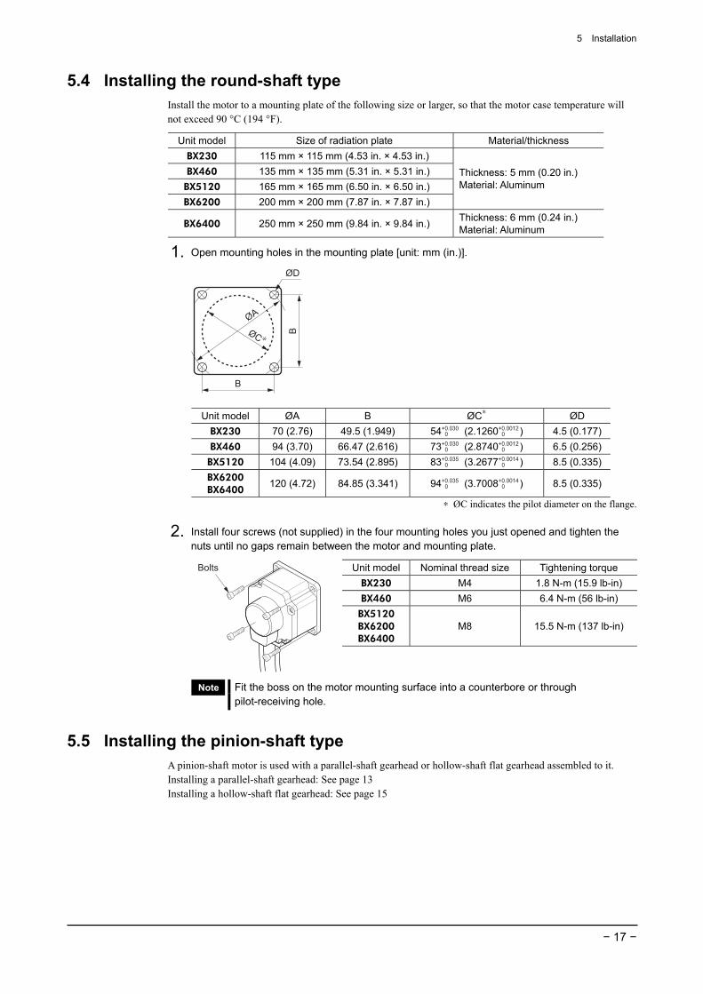
5.4 Installing the round-shaft type Install the motor to a mounting plate of the following size or larger, so that the motor case temperature will not exceed 90 °C (194 °F).
Unit model Size of radiation plate Material/thickness BX230 115 mm × 115 mm (4.53 in. × 4.53 in.) BX460 135 mm × 135 mm (5.31 in. × 5.31 in.) BX5120 165 mm × 165 mm (6.50 in. × 6.50 in.) BX6200 200 mm × 200 mm (7.87 in. × 7.87 in.)
Thickness: 5 mm (0.20 in.) Material: Aluminum
BX6400 250 mm × 250 mm (9.84 in. × 9.84 in.) Thickness: 6 mm (0.24 in.) Material: Aluminum
1. Open mounting holes in the mounting plate [unit: mm (in.)].
ØC ∗
B
B
ØA
ØD
Unit model ØA B ØC∗ ØD BX230 70 (2.76) 49.5 (1.949) 54+0.030
0 (2.1260+0.0012 0 ) 4.5 (0.177)
BX460 94 (3.70) 66.47 (2.616) 73+0.030 0 (2.8740+0.0012
0 ) 6.5 (0.256)BX5120 104 (4.09) 73.54 (2.895) 83+0.035
0 (3.2677+0.0014 0 ) 8.5 (0.335)
BX6200 BX6400
120 (4.72) 84.85 (3.341) 94+0.035 0 (3.7008+0.0014
0 ) 8.5 (0.335)
∗ ØC indicates the pilot diameter on the flange.
2. Install four screws (not supplied) in the four mounting holes you just opened and tighten the nuts until no gaps remain between the motor and mounting plate.
Unit model Nominal thread size Tightening torque BX230 M4 1.8 N-m (15.9 lb-in) BX460 M6 6.4 N-m (56 lb-in) BX5120 BX6200 BX6400
M8 15.5 N-m (137 lb-in)
Bolts
Note Fit the boss on the motor mounting surface into a counterbore or through pilot-receiving hole.
5.5 Installing the pinion-shaft type A pinion-shaft motor is used with a parallel-shaft gearhead or hollow-shaft flat gearhead assembled to it. Installing a parallel-shaft gearhead: See page 13 Installing a hollow-shaft flat gearhead: See page 15
5 Installation
− 18 −
5.6 Installing a load on the combination-type parallel gearhead or round-shaft type
When installing a load on the motor (gearhead), align the center of the motor output shaft (gearhead output shaft) with the center of the load shaft.
Note • When coupling the motor (gearhead) with a load, pay attention to centering, belt tension, parallelism of pulleys, etc. Also, securely affix the tightening screws of the coupling or pulleys.
• When installing a load, do not damage the motor output shaft (gearhead output shaft) or bearing. Forcing in the load by driving it with a hammer, etc., may break the bearing. Do not apply any excessive force to the output shaft.
• Do not modify or machine the motor (gearhead) output shaft. The bearing may be damaged or motor (gearhead) may break.
Output shaft shape
• Combination-type parallel-shaft gearhead A key groove is provided on the output shaft of each combination-type parallel-shaft gearhead. Form a key groove on the load side and affix the load using the supplied parallel key.
Unit model Parallel key dimension BX230 4 mm (0.1575 in.) BX460 5 mm (0.1969 in.)
BX5120、BX6200、BX6400 6 mm (0.2362 in.) On the GFS6G , the parallel key is affixed to the gearhead output shaft.
• Round-shaft type A flat section is provided on the motor output shaft of each round-shaft motor. Apply a double-point screw, etc., at the flat section to securely affix the load and prevent it from spinning.
How to install a load
• Using a coupling Align the centerline of the motor (gearhead) output shaft with the centerline of the load shaft.
• Using a belt Adjust the motor (gearhead) output shaft to lie parallel with the load shaft and form right angles between the output shaft/load shaft and the line connecting the centers of both pulleys.
• Using a gear Adjust the motor (gearhead) output shaft to lie parallel with the gear shaft and allow the output shaft to mesh correctly with the centers of the gear teeth.
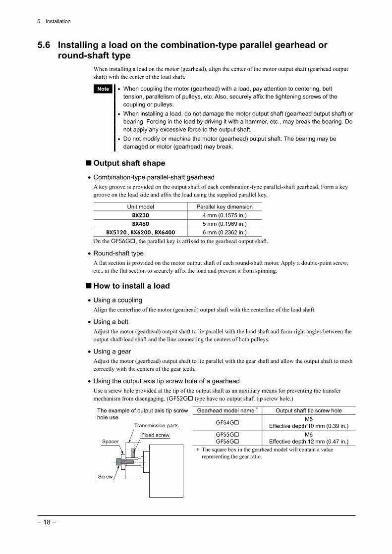
• Using the output axis tip screw hole of a gearhead Use a screw hole provided at the tip of the output shaft as an auxiliary means for preventing the transfer mechanism from disengaging. (GFS2G type have no output shaft tip screw hole.)
Gearhead model name ∗ Output shaft tip screw hole
GFS4G M5
Effective depth 10 mm (0.39 in.) GFS5G GFS6G
M6 Effective depth 12 mm (0.47 in.)
The example of output axis tip screw hole use
Fixed screw
Screw
Spacer
Transmission parts
∗ The square box in the gearhead model will contain a value representing the gear ratio.

5 Installation
− 19 −
5.7 Installing a load on the combination-type hollow-shaft flat gearhead If the motor is subject to a strong impact upon instantaneous stop or receives a large overhung load, use a stepped load shaft.
Note • Apply grease (molybdenum disulfide grease, etc.) on the surface of the load shaft and inner walls of the hollow output shaft to prevent seizure.
• When installing the load shaft using an end plate, the safety cover (supplied) cannot be attached due to contact between the safety cover and hexagonal socket head screw. Take safety measures against rotating part.
Stepped load shaft
• Affixing method using retaining ring Install each hexagonal socket head screw over a retaining ring, spacer, flat washer and spring washer and securely affix the ring.
Flat washer
Spacer
Retaining ring
Stepped load shaft
Parallel key
Spring washer
Hexagonal socket head screw
Flat washer
SpacerParallel keyØ
D
Hollow output shaft
Hexagonal sockethead screw
Spring washer
Retaining ring
Load shaft
• Affixing method using end plate Affix the load shaft by tightening the hexagonal socket head screw over an end plate, flat washer and spring washer.
Flat washer
End plate
Parallel key
Spring washer
Hexagonal socket head screw
Hollow output shaft
Hexagonal sockethead screw
Spring washer
Flat washer
End plateParallel key
Load shaft
ØD
Stepped load shaft
Non-stepped load shaft Install each hexagonal socket head screw over a retaining ring, spacer, flat washer and spring washer and securely affix the ring. Also insert a spacer on the load shaft side.
Spacer
Retaining ringHollow output shaft
Hexagonal sockethead screw
Spring washer
Flat washer
SpacerParallel key
Load shaft
Flat washer
SpacerRetaining ring
Spring washerHexagonal socket head screw
Spacer
Load shaft
Parallel key
5 Installation
− 20 −
Recommended load shaft installation dimensions [Unit:mm (in.)]
Unit model Inner diameter of hollow shaft
Recommended diameter of load shaft
Nominal diameter of
retaining ring
Applicable screw
Spacer thickness
Outer diameter of stepped shaft (ØD)
BX230 Ø12+0.027 0 (Ø0.4724+0.0011
0 ) Ø12 0-0.018 (Ø0.4724 0
-0.0007) Ø12 (Ø0.47) M4 3 (0.12) 20 (0.79) BX460 Ø15+0.027
0 (Ø0.5906+0.0011 0 ) Ø15 0
-0.018 (Ø0.5906 0-0.0007) Ø15 (Ø0.59) M5 4 (0.16) 25 (0.98)
BX5120 Ø20+0.033 0 (Ø0.7874+0.0013
0 ) Ø20 0-0.021 (Ø0.7874 0
-0.0008) Ø20 (Ø0.79) M6 5 (0.20) 30 (1.18) BX6200 BX6400
Ø25+0.033 0 (0.9843+0.0013
0 ) Ø25 0-0.021 (0.9843 0
-0.0008) Ø25 (Ø0.98) M10 6 (0.24) 40 (1.57)
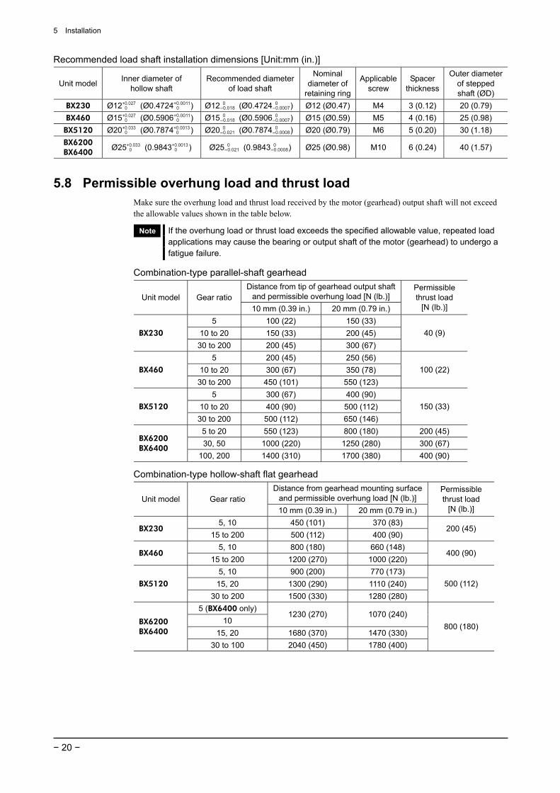
5.8 Permissible overhung load and thrust load Make sure the overhung load and thrust load received by the motor (gearhead) output shaft will not exceed the allowable values shown in the table below.
Note If the overhung load or thrust load exceeds the specified allowable value, repeated load applications may cause the bearing or output shaft of the motor (gearhead) to undergo a fatigue failure.
Combination-type parallel-shaft gearhead Distance from tip of gearhead output shaft
and permissible overhung load [N (lb.)] Unit model Gear ratio 10 mm (0.39 in.) 20 mm (0.79 in.)
Permissible thrust load
[N (lb.)]
5 100 (22) 150 (33) 10 to 20 150 (33) 200 (45) BX230
30 to 200 200 (45) 300 (67) 40 (9)
5 200 (45) 250 (56) 10 to 20 300 (67) 350 (78) BX460
30 to 200 450 (101) 550 (123) 100 (22)
5 300 (67) 400 (90) 10 to 20 400 (90) 500 (112) BX5120
30 to 200 500 (112) 650 (146) 150 (33)
5 to 20 550 (123) 800 (180) 200 (45) 30, 50 1000 (220) 1250 (280) 300 (67) BX6200
BX6400 100, 200 1400 (310) 1700 (380) 400 (90)
Combination-type hollow-shaft flat gearhead Distance from gearhead mounting surface
and permissible overhung load [N (lb.)] Unit model Gear ratio 10 mm (0.39 in.) 20 mm (0.79 in.)
Permissible thrust load
[N (lb.)]
5, 10 450 (101) 370 (83) BX230
15 to 200 500 (112) 400 (90) 200 (45)
5, 10 800 (180) 660 (148) BX460
15 to 200 1200 (270) 1000 (220) 400 (90)
5, 10 900 (200) 770 (173) 15, 20 1300 (290) 1110 (240) BX5120
30 to 200 1500 (330) 1280 (280) 500 (112)
5 (BX6400 only) 10
1230 (270) 1070 (240)
15, 20 1680 (370) 1470 (330) BX6200 BX6400
30 to 100 2040 (450) 1780 (400)
800 (180)
5 Installation
− 21 −
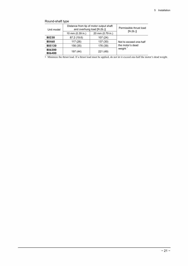
Round-shaft type Distance from tip of motor output shaft
and overhung load [N (lb.)] Unit model 10 mm (0.39 in.) 20 mm (0.79 in.)
Permissible thrust load [N (lb.)]
BX230 87.2 (19.6) 107 (24) BX460 117 (26) 137 (30) BX5120 156 (35) 176 (39) BX6200 BX6400
197 (44) 221 (49)
Not to exceed one-half the motor’s dead weight ∗
∗ Minimize the thrust load. If a thrust load must be applied, do not let it exceed one-half the motor’s dead weight.
5 Installation
− 22 −
5.9 Installing the driver
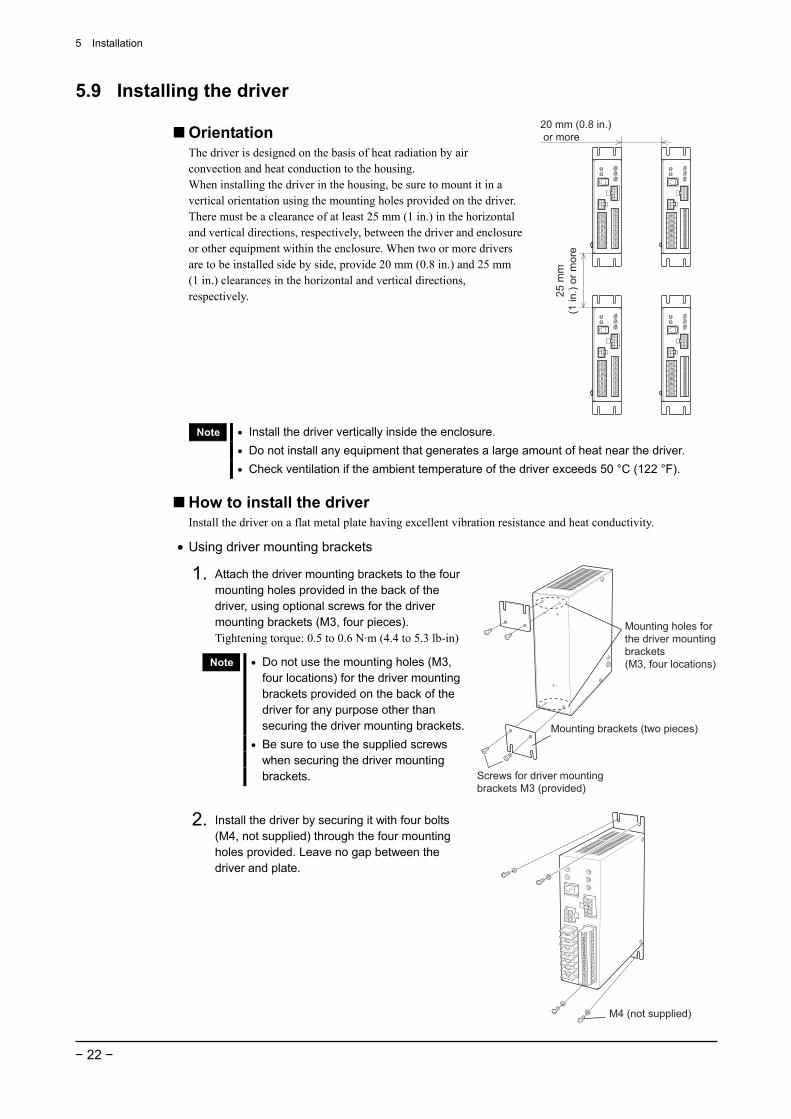
Orientation The driver is designed on the basis of heat radiation by air convection and heat conduction to the housing. When installing the driver in the housing, be sure to mount it in a vertical orientation using the mounting holes provided on the driver. There must be a clearance of at least 25 mm (1 in.) in the horizontal and vertical directions, respectively, between the driver and enclosure or other equipment within the enclosure. When two or more drivers are to be installed side by side, provide 20 mm (0.8 in.) and 25 mm (1 in.) clearances in the horizontal and vertical directions, respectively.
20 mm (0.8 in.) or more
25 m
m(1
in.)
or m
ore
Note • Install the driver vertically inside the enclosure. • Do not install any equipment that generates a large amount of heat near the driver. • Check ventilation if the ambient temperature of the driver exceeds 50 °C (122 °F).
How to install the driver Install the driver on a flat metal plate having excellent vibration resistance and heat conductivity.
• Using driver mounting brackets
1. Attach the driver mounting brackets to the four mounting holes provided in the back of the driver, using optional screws for the driver mounting brackets (M3, four pieces). Tightening torque: 0.5 to 0.6 N·m (4.4 to 5.3 lb-in)
Note • Do not use the mounting holes (M3, four locations) for the driver mounting brackets provided on the back of the driver for any purpose other than securing the driver mounting brackets.
• Be sure to use the supplied screws when securing the driver mounting brackets. Screws for driver mounting
brackets M3 (provided)
Mounting brackets (two pieces)
Mounting holes forthe driver mountingbrackets(M3, four locations)
2. Install the driver by securing it with four bolts (M4, not supplied) through the four mounting holes provided. Leave no gap between the driver and plate.
M4 (not supplied)
5 Installation
− 23 −
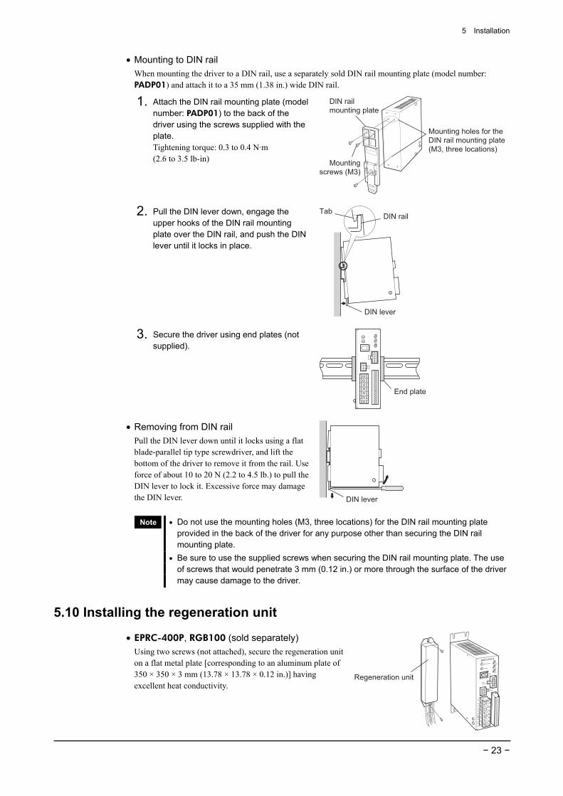
• Mounting to DIN rail When mounting the driver to a DIN rail, use a separately sold DIN rail mounting plate (model number: PADP01) and attach it to a 35 mm (1.38 in.) wide DIN rail.
1. Attach the DIN rail mounting plate (model number: PADP01) to the back of the driver using the screws supplied with the plate. Tightening torque: 0.3 to 0.4 N·m (2.6 to 3.5 lb-in)
DIN railmounting plate
Mountingscrews (M3)
Mounting holes for the DIN rail mounting plate(M3, three locations)
2. Pull the DIN lever down, engage the upper hooks of the DIN rail mounting plate over the DIN rail, and push the DIN lever until it locks in place.
TabDIN rail
DIN lever
3. Secure the driver using end plates (not supplied).
End plate
• Removing from DIN rail Pull the DIN lever down until it locks using a flat blade-parallel tip type screwdriver, and lift the bottom of the driver to remove it from the rail. Use force of about 10 to 20 N (2.2 to 4.5 lb.) to pull the DIN lever to lock it. Excessive force may damage the DIN lever. DIN lever
Note • Do not use the mounting holes (M3, three locations) for the DIN rail mounting plate provided in the back of the driver for any purpose other than securing the DIN rail mounting plate.
• Be sure to use the supplied screws when securing the DIN rail mounting plate. The use of screws that would penetrate 3 mm (0.12 in.) or more through the surface of the driver may cause damage to the driver.
5.10 Installing the regeneration unit
• EPRC-400P, RGB100 (sold separately) Using two screws (not attached), secure the regeneration unit on a flat metal plate [corresponding to an aluminum plate of 350 × 350 × 3 mm (13.78 × 13.78 × 0.12 in.)] having excellent heat conductivity.
Regeneration unit

5 Installation
− 24 −
5.11 Installing and wiring in compliance with EMC Directive
General
• EMC Directive The BX series has been designed and manufactured for incorporation in general industrial machinery. The EMC Directive requires that the equipment incorporating this product comply with these directives. The installation and wiring method for the motor and driver are the basic methods that would effectively allow the customer’s equipment to be compliant with the EMC Directive. The compliance of the final machinery with the EMC Directive will depend on such factors as the configuration, wiring, layout and risk involved in the control-system equipment and electrical parts. It therefore must be verified through EMC measures by the customer of the machinery.
• Applicable standards EMI Emission Tests EN 61000-6-4 EMS Immunity Tests EN 61000-6-2
Installing and wiring in compliance with EMC Directive Effective measures must be taken against the EMI that the BX series may give to adjacent control-system equipment, as well as the EMS of the BX series itself, in order to prevent a serious functional impediment in the machinery. The use of the following installation and wiring methods will enable the BX series to be compliant with the EMC Directive (the aforementioned compliance standards).
• Connecting mains filter for power source line Connect a mains filter in the AC input line to prevent the noise generated in the driver from propagating externally through the power-source line. Use a mains filter or equivalent as below table.
Manufacturer Single-phase 100 V Single-phase 200 V Three-phase 200 VSchaffner EMC AG FN2070-10-06 − FN251-8-07 EPCOS AG B84113-C-B110 − − TDK Corporation − ZAG2210-11S − TDK-Lambda Corporation MC1210 MC1210 MC1310
• Install the mains filter as close to the driver as possible, and use cable clamps and other means to secure the input and output cables firmly to the surface of the enclosure.
• Connect the ground terminal of the mains filter to the grounding point, using as thick and short a wire as possible.
• Do not place the AC input cable (AWG18: 0.75 mm2 or more) parallel with the mains-filter output cable (AWG18: 0.75 mm2 or more). Parallel placement will reduce mains-filter effectiveness if the enclosure’s internal noise is directly coupled to the power supply cable by means of stray capacitance.
5 Installation
− 25 −
How to ground The cable used to ground the driver, motor and mains filter must be as thick and short as possible so that no potential difference is generated. Choose a large, thick and uniformly conductive surface for the grounding point.
• How to ground the driver Use the Protective Earth Terminal located on the side of the driver. Refer to page 29 for the way to ground the driver.
• How to ground the motor
BX230, BX460, BX5120
Ground the Frame Ground terminal of the motor cable. Or, ground the motor using one of its four mounting holes. At this time, insulate the Frame Ground terminal extending from the motor cable without connecting it to ground.
BX6200, BX6400 Ground the motor’s Protective Earth Terminal.
Refer to page 29 for the way to ground the motor.
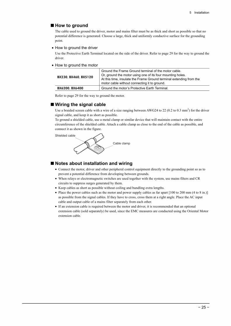
Wiring the signal cable Use a braided screen cable with a wire of a size ranging between AWG24 to 22 (0.2 to 0.3 mm2) for the driver signal cable, and keep it as short as possible. To ground a shielded cable, use a metal clamp or similar device that will maintain contact with the entire circumference of the shielded cable. Attach a cable clamp as close to the end of the cable as possible, and connect it as shown in the figure.
Cable clamp
Shielded cable
Notes about installation and wiring • Connect the motor, driver and other peripheral control equipment directly to the grounding point so as to
prevent a potential difference from developing between grounds. • When relays or electromagnetic switches are used together with the system, use mains filters and CR
circuits to suppress surges generated by them. • Keep cables as short as possible without coiling and bundling extra lengths. • Place the power cables such as the motor and power supply cables as far apart [100 to 200 mm (4 to 8 in.)]
as possible from the signal cables. If they have to cross, cross them at a right angle. Place the AC input cable and output cable of a mains filter separately from each other.
• If an extension cable is required between the motor and driver, it is recommended that an optional extension cable (sold separately) be used, since the EMC measures are conducted using the Oriental Motor extension cable.
5 Installation
− 26 −
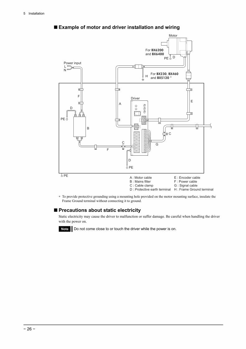
Example of motor and driver installation and wiring
B
F
LN
C
DA
C
E
Motor
Driver
Power input
G
F
D
PE
PE
PE
PE
For BX230, BX460and BX5120 ∗
For BX6200and BX6400
D
H
E : Encoder cableF : Power cableG : Signal cableH : Frame Ground terminal
A : Motor cableB : Mains filterC : Cable clampD : Protective earth terminal
∗ To provide protective grounding using a mounting hole provided on the motor mounting surface, insulate the Frame Ground terminal without connecting it to ground.
Precautions about static electricity Static electricity may cause the driver to malfunction or suffer damage. Be careful when handling the driver with the power on.
Note Do not come close to or touch the driver while the power is on.
6 Connection
− 27 −
6 Connection The section covers the method of connecting the driver and power source/regeneration unit/motor/external control equipment, earth connection method, an example of connection and input/output signals.
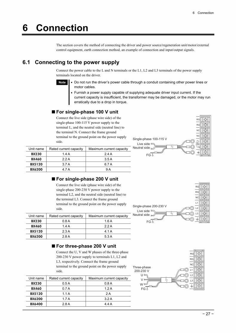
6.1 Connecting to the power supply Connect the power cable to the L and N terminals or the L1, L2 and L3 terminals of the power supply terminals located on the driver.
Note • Do not run the driver’s power cable through a conduit containing other power lines or motor cables.
• Furnish a power supply capable of supplying adequate driver input current. If the current capacity is insufficient, the transformer may be damaged, or the motor may run erratically due to a drop in torque.
For single-phase 100 V unit Connect the live side (phase wire side) of the single-phase 100-115 V power supply to the terminal L, and the neutral side (neutral line) to the terminal N. Connect the frame ground terminal to the ground point on the power supply side.
Unit name Rated current capacity Maximum current capacity BX230 1.4 A 2.4 A BX460 2.2 A 3.5 A BX5120 3.7 A 6.7 A BX6200 4.7 A 9 A
Single-phase 100-115 VLive side
Neutral side
FG
For single-phase 200 V unit Connect the live side (phase wire side) of the single-phase 200-230 V power supply to the terminal L2, and the neutral side (neutral line) to the terminal L3. Connect the frame ground terminal to the ground point on the power supply side.
Unit name Rated current capacity Maximum current capacity BX230 0.8 A 1.6 A BX460 1.4 A 2.2 A BX5120 2.3 A 4.1 A BX6200 2.8 A 5.3 A
Single-phase 200-230 VLive side
Neutral side
FG
For three-phase 200 V unit Connect the U, V and W phases of the three-phase 200-230 V power supply to terminals L1, L2 and L3, respectively. Connect the frame ground terminal to the ground point on the power supply side.
Unit name Rated current capacity Maximum current capacity BX230 0.5 A 0.8 A BX460 0.7 A 1.2 A BX5120 1.1 A 2 A BX6200 1.7 A 3.2 A BX6400 2.8 A 4.4 A
UVW
Three-phase200-230 V
FG

6 Connection
− 28 −
Terminal screw size and applicable lead wire size for power connection For connection, use an insulated round crimp terminal. • Terminal screw size: M3 • Tightening torque: 0.8 N·m (7.0 lb-in) • Applicable lead wire size: AWG16 to 18 (1.25 to 0.75 mm2)
Ø3.2 mm (0.126 in.)or more
9 mm (0.35 in.)or more6.
2 m
m (0
.24
in.)
or le
ss
6.2 Turning on the power
Power supply
ALARM output
ON
ON
ON
ON
Enable
Turn on power again
Enable
1 s or less
30 sor more
Note After shutting down the power, wait at least 30 seconds before turning it back on.
6.3 Connecting the regeneration unit • Connect the two thick lead wires (AWG18) of the regeneration unit to the driver’s RG terminals. • The thin lead wires (AWG22) of the regeneration unit are thermal protector output.
Provide a measure on the thermal protector contact to shut off the power supply in the event an error is detected.
Regeneration unit specifications Applicable product ∗1 BX230 , BX460 , BX5120 BX6200 , BX6400S
Model EPRC-400P RGB100 Continuous regenerative power ∗2 100 W 100 W
Resistance 400 Ω 150 Ω
Thermostat operation temperature
Operation: Open at 150±7 °C (302±45 °F) Reset: Close at 145±12 °C (293±54 °F) (Normally closed)
Operation: Open at 150±7 °C (302±45 °F)Reset: Close at 145±12 °C (293±54 °F) (Normally closed)
Electrical rating of thermostat
120 VAC, 4 A 30 VDC, 4 A (minimum current: 5 mA at 12 VDC)
120 VAC, 4 A 30 VDC, 4 A (minimum current: 5 mA)
∗1 in the model names indicates the power source specification (A or C). ∗2 Install the regeneration unit in a location where a radiation capacity equivalent to a heat sink [material:
aluminum, 350 × 350 × 3 mm (13.78 × 13.78 × 0.12 in.)] is provided.
RGB100
CN4
RG∗2
RG∗2
Driver
AWG22
AWG18
R:1
50 Ω
∗1
150°
C (N
.C.)
∗1 Using the EPRC-400P R: 400 Ω ∗2 The RG has no polarity.
Warning In the event the thermal protector is triggered, shut off the power.
6 Connection
− 29 −
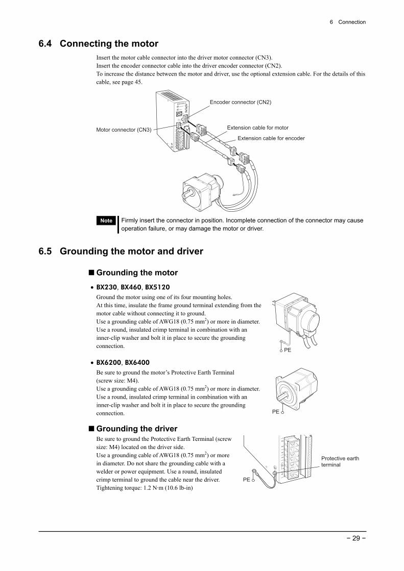
6.4 Connecting the motor Insert the motor cable connector into the driver motor connector (CN3). Insert the encoder connector cable into the driver encoder connector (CN2). To increase the distance between the motor and driver, use the optional extension cable. For the details of this cable, see page 45.
Extension cable for encoder
Extension cable for motor
Encoder connector (CN2)
Motor connector (CN3)
Note Firmly insert the connector in position. Incomplete connection of the connector may cause operation failure, or may damage the motor or driver.
6.5 Grounding the motor and driver
Grounding the motor
• BX230, BX460, BX5120 Ground the motor using one of its four mounting holes. At this time, insulate the frame ground terminal extending from the motor cable without connecting it to ground. Use a grounding cable of AWG18 (0.75 mm2) or more in diameter.Use a round, insulated crimp terminal in combination with an inner-clip washer and bolt it in place to secure the grounding connection.
PE
• BX6200, BX6400 Be sure to ground the motor’s Protective Earth Terminal (screw size: M4). Use a grounding cable of AWG18 (0.75 mm2) or more in diameter.Use a round, insulated crimp terminal in combination with an inner-clip washer and bolt it in place to secure the grounding connection. PE
Grounding the driver Be sure to ground the Protective Earth Terminal (screw size: M4) located on the driver side. Use a grounding cable of AWG18 (0.75 mm2) or more in diameter. Do not share the grounding cable with a welder or power equipment. Use a round, insulated crimp terminal to ground the cable near the driver. Tightening torque: 1.2 N·m (10.6 lb-in)
Protective earthterminal
PE
6 Connection
− 30 −
6.6 Connecting input/output signal
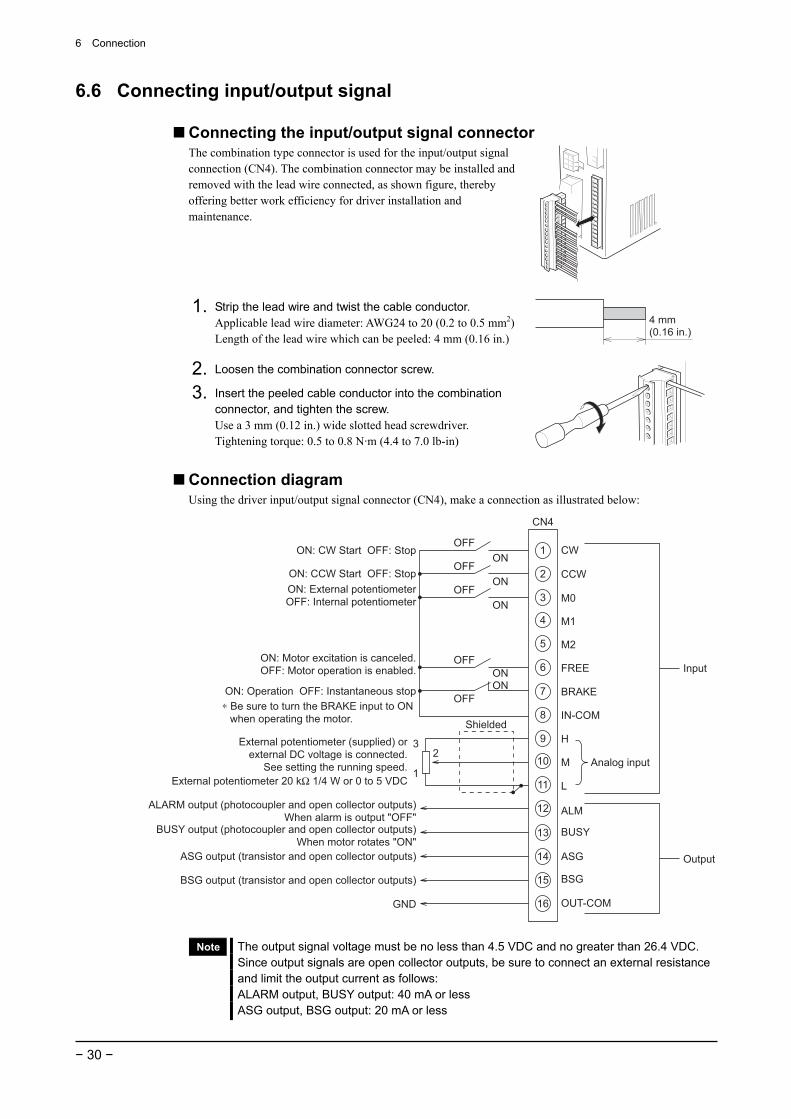
Connecting the input/output signal connector The combination type connector is used for the input/output signal connection (CN4). The combination connector may be installed and removed with the lead wire connected, as shown figure, thereby offering better work efficiency for driver installation and maintenance.
1. Strip the lead wire and twist the cable conductor. Applicable lead wire diameter: AWG24 to 20 (0.2 to 0.5 mm2) Length of the lead wire which can be peeled: 4 mm (0.16 in.)
4 mm(0.16 in.)
2. Loosen the combination connector screw.
3. Insert the peeled cable conductor into the combination connector, and tighten the screw. Use a 3 mm (0.12 in.) wide slotted head screwdriver. Tightening torque: 0.5 to 0.8 N·m (4.4 to 7.0 lb-in)
Connection diagram Using the driver input/output signal connector (CN4), make a connection as illustrated below:
OFFON
OFFON
OFFON
OFFON
OFFON
1
23
CN4
External potentiometer 20 kΩ 1/4 W or 0 to 5 VDC
ON: CW Start OFF: Stop
ON: CCW Start OFF: StopON: External potentiometerOFF: Internal potentiometer
ON: Operation OFF: Instantaneous stop
External potentiometer (supplied) orexternal DC voltage is connected.
See setting the running speed.
ALARM output (photocoupler and open collector outputs)When alarm is output "OFF"
BUSY output (photocoupler and open collector outputs)When motor rotates "ON"
ASG output (transistor and open collector outputs)
BSG output (transistor and open collector outputs)
CW
CCW
M0
M1
M2
FREE
BRAKE
IN-COM
M
H
L
ALM
BUSY
ASG
BSG
OUT-COM
Analog input
GND
∗ Be sure to turn the BRAKE input to ONwhen operating the motor.
1
2
3
4
5
6
7
8
9
10
11
12
13
16
14
15
Input
Output
ON: Motor excitation is canceled.OFF: Motor operation is enabled.
Shielded
Note The output signal voltage must be no less than 4.5 VDC and no greater than 26.4 VDC. Since output signals are open collector outputs, be sure to connect an external resistance and limit the output current as follows: ALARM output, BUSY output: 40 mA or less ASG output, BSG output: 20 mA or less
6 Connection
− 31 −
• Input signal The CW, CCW, M0, M1, M2, FREE and BRAKE inputs are photocoupler inputs. Internal resistor: 2.3 kΩ Internal voltage: +15 V The M1 and M2 inputs are connected when using the system upgrading tool (OPX-1A).
• Output signal ALARM and BUSY outputs are photocoupler and open collector outputs. ASG and BSG output are transistor and open collector outputs. External operating conditions: ALARM and BUSY outputs: 4.5 to 26.4 VDC without exceeding 40 mA ASG and BSG outputs: 4.5 to 26.4 VDC without exceeding 20 mA
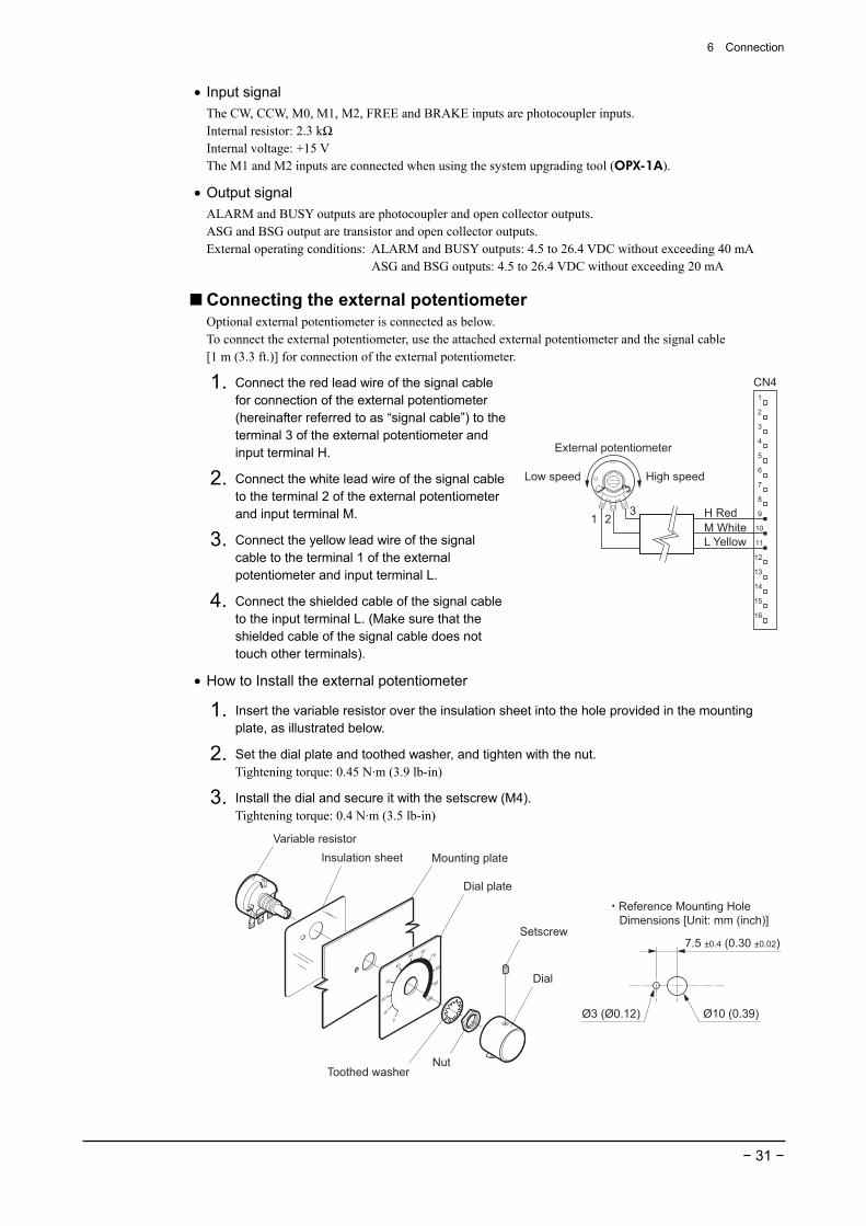
Connecting the external potentiometer Optional external potentiometer is connected as below. To connect the external potentiometer, use the attached external potentiometer and the signal cable [1 m (3.3 ft.)] for connection of the external potentiometer.
1. Connect the red lead wire of the signal cable for connection of the external potentiometer (hereinafter referred to as “signal cable”) to the terminal 3 of the external potentiometer and input terminal H.
2. Connect the white lead wire of the signal cable to the terminal 2 of the external potentiometer and input terminal M.
3. Connect the yellow lead wire of the signal cable to the terminal 1 of the external potentiometer and input terminal L.
4. Connect the shielded cable of the signal cable to the input terminal L. (Make sure that the shielded cable of the signal cable does not touch other terminals).
External potentiometer
1 3
High speedLow speed
213
3
4
1
2
5
6
7
8
9
10
11
12
13
14
15
16
CN4
H RedM WhiteL Yellow
• How to Install the external potentiometer
1. Insert the variable resistor over the insulation sheet into the hole provided in the mounting plate, as illustrated below.
2. Set the dial plate and toothed washer, and tighten with the nut. Tightening torque: 0.45 N·m (3.9 lb-in)
3. Install the dial and secure it with the setscrew (M4). Tightening torque: 0.4 N·m (3.5 lb-in)
・ Reference Mounting Hole Dimensions [Unit: mm (inch)]
Ø3 (Ø0.12)
7.5 ±0.4 (0.30 ±0.02)
Ø10 (0.39)
Dial
NutToothed washer
Dial plate
Mounting plateInsulation sheetVariable resistor
Setscrew
6 Connection
− 32 −
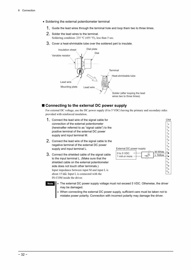
• Soldering the external potentiometer terminal
1. Guide the lead wires through the terminal hole and loop them two to three times.
2. Solder the lead wires to the terminal. Soldering condition: 235 °C (455 °F), less than 5 sec.
3. Cover a heat-shrinkable tube over the soldered part to insulate.
DialVariable resistor
Dial plate
Mounting plate
Lead wire
Insulation sheet
Lead wire
Terminal
Heat-shrinkable tube
Solder (after looping the lead wires two to three times)
Connecting to the external DC power supply For external DC voltage, use the DC power supply (0 to 5 VDC) having the primary and secondary sides provided with reinforced insulation.
1. Connect the lead wire of the signal cable for connection of the external potentiometer (hereinafter referred to as “signal cable”) to the positive terminal of the external DC power supply and input terminal M.
2. Connect the lead wire of the signal cable to the negative terminal of the external DC power supply and input terminal L.
3. Connect the shielded cable of the signal cable to the input terminal L. (Make sure that the shielded cable on the external potentiometer side does not touch other terminals.) Input impedance between input M and input L is about 15 kΩ. Input L is connected with the IN-COM inside the driver.
External DC power supply
0 to 5 VDC1 mA or more
M WhiteL Yellow
3
4
1
2
5
6
7
8
9
10
11
12
13
14
15
16
CN4
Note • The external DC power supply voltage must not exceed 5 VDC. Otherwise, the driver may be damaged.
• When connecting the external DC power supply, sufficient care must be taken not to mistake power polarity. Connection with incorrect polarity may damage the driver.
6 Connection
− 33 −
6.7 About input signal and output signal
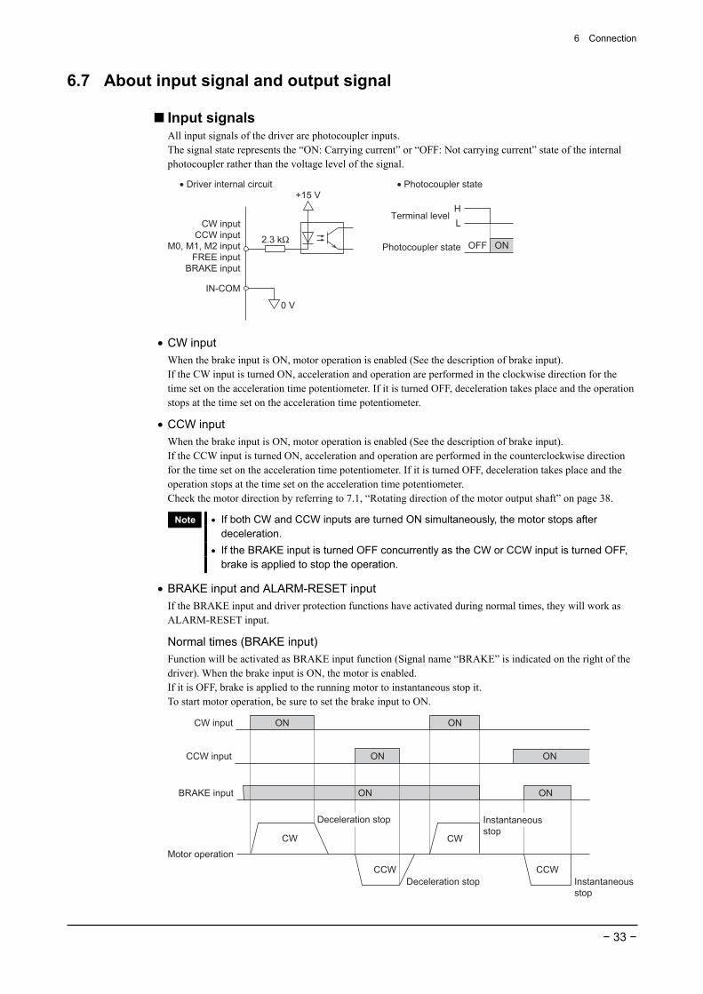
Input signals All input signals of the driver are photocoupler inputs. The signal state represents the “ON: Carrying current” or “OFF: Not carrying current” state of the internal photocoupler rather than the voltage level of the signal.
CW inputCCW input
M0, M1, M2 inputFREE input
BRAKE input
+15 V
IN-COM
2.3 kΩ
0 V
Terminal level
• Photocoupler state• Driver internal circuit
Photocoupler state OFF ON
HL
• CW input When the brake input is ON, motor operation is enabled (See the description of brake input). If the CW input is turned ON, acceleration and operation are performed in the clockwise direction for the time set on the acceleration time potentiometer. If it is turned OFF, deceleration takes place and the operation stops at the time set on the acceleration time potentiometer.
• CCW input When the brake input is ON, motor operation is enabled (See the description of brake input). If the CCW input is turned ON, acceleration and operation are performed in the counterclockwise direction for the time set on the acceleration time potentiometer. If it is turned OFF, deceleration takes place and the operation stops at the time set on the acceleration time potentiometer. Check the motor direction by referring to 7.1, “Rotating direction of the motor output shaft” on page 38.
Note • If both CW and CCW inputs are turned ON simultaneously, the motor stops after deceleration.
• If the BRAKE input is turned OFF concurrently as the CW or CCW input is turned OFF, brake is applied to stop the operation.
• BRAKE input and ALARM-RESET input If the BRAKE input and driver protection functions have activated during normal times, they will work as ALARM-RESET input.
Normal times (BRAKE input) Function will be activated as BRAKE input function (Signal name “BRAKE” is indicated on the right of the driver). When the brake input is ON, the motor is enabled. If it is OFF, brake is applied to the running motor to instantaneous stop it. To start motor operation, be sure to set the brake input to ON.
Deceleration stop
CW
CW input
BRAKE input
CCW input
Motor operation
ON
CCWDeceleration stop
CW
CCWInstantaneousstop
ON
ON
ON
ONON
Instantaneousstop
6 Connection
− 34 −
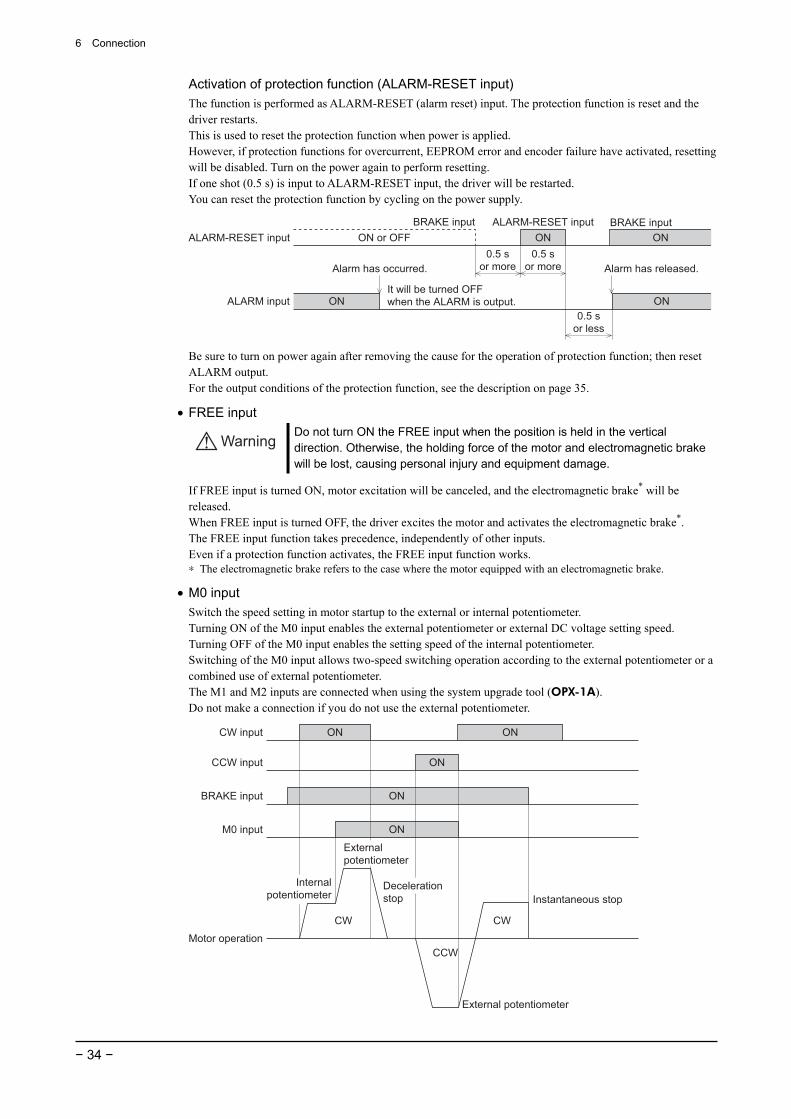
Activation of protection function (ALARM-RESET input) The function is performed as ALARM-RESET (alarm reset) input. The protection function is reset and the driver restarts. This is used to reset the protection function when power is applied. However, if protection functions for overcurrent, EEPROM error and encoder failure have activated, resetting will be disabled. Turn on the power again to perform resetting. If one shot (0.5 s) is input to ALARM-RESET input, the driver will be restarted. You can reset the protection function by cycling on the power supply.
0.5 sor more
ALARM-RESET inputBRAKE input
ALARM input
ON or OFF
ON
ON
ON
Alarm has occurred. Alarm has released.
ON0.5 s
or more
0.5 sor less
BRAKE inputALARM-RESET input
It will be turned OFFwhen the ALARM is output.
Be sure to turn on power again after removing the cause for the operation of protection function; then reset ALARM output. For the output conditions of the protection function, see the description on page 35.
• FREE input
Warning Do not turn ON the FREE input when the position is held in the vertical direction. Otherwise, the holding force of the motor and electromagnetic brake will be lost, causing personal injury and equipment damage.
If FREE input is turned ON, motor excitation will be canceled, and the electromagnetic brake* will be released. When FREE input is turned OFF, the driver excites the motor and activates the electromagnetic brake*. The FREE input function takes precedence, independently of other inputs. Even if a protection function activates, the FREE input function works. ∗ The electromagnetic brake refers to the case where the motor equipped with an electromagnetic brake.
• M0 input Switch the speed setting in motor startup to the external or internal potentiometer. Turning ON of the M0 input enables the external potentiometer or external DC voltage setting speed. Turning OFF of the M0 input enables the setting speed of the internal potentiometer. Switching of the M0 input allows two-speed switching operation according to the external potentiometer or a combined use of external potentiometer. The M1 and M2 inputs are connected when using the system upgrade tool (OPX-1A). Do not make a connection if you do not use the external potentiometer.
Decelerationstop
CW
CW input
BRAKE input
CCW input
Motor operation
ON
CCW
Instantaneous stop
CW
ON
ON
ON
M0 input ON
Internalpotentiometer
Externalpotentiometer
External potentiometer
6 Connection
− 35 −
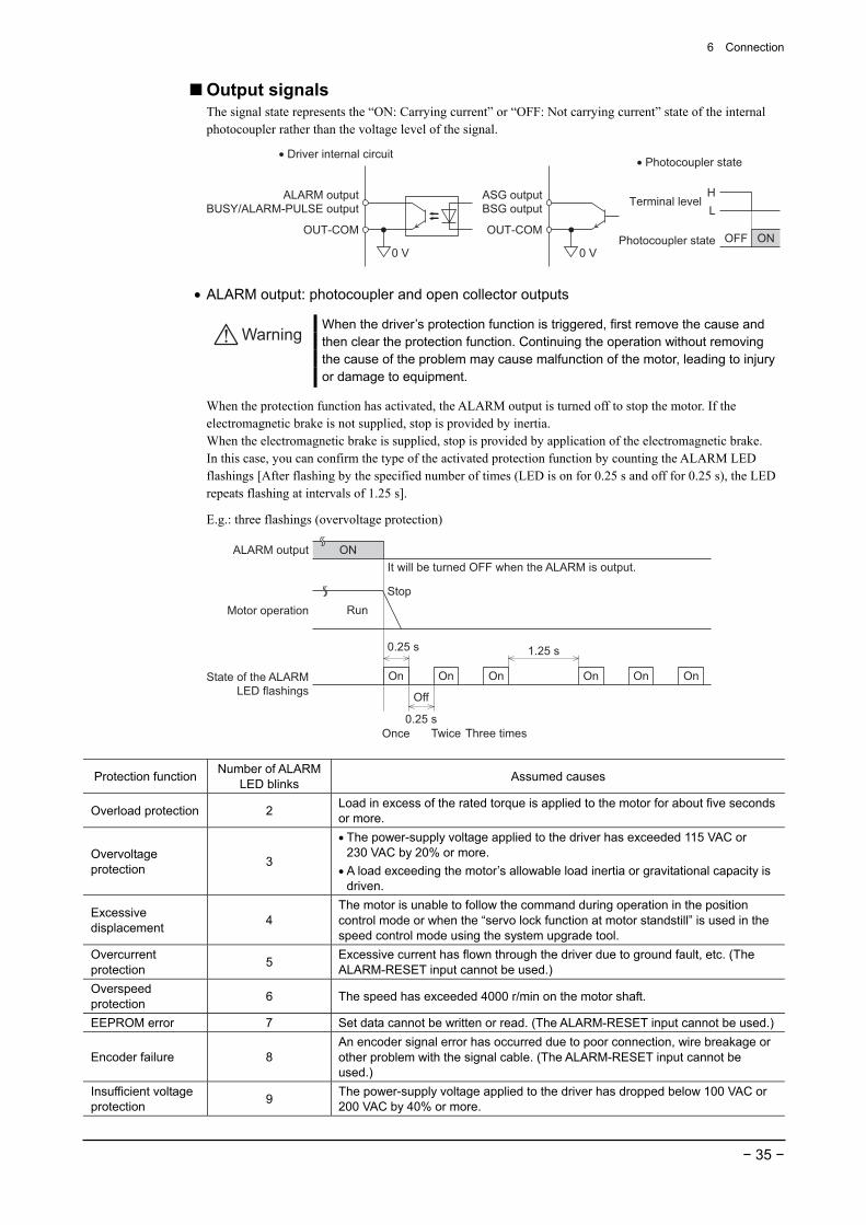
Output signals The signal state represents the “ON: Carrying current” or “OFF: Not carrying current” state of the internal photocoupler rather than the voltage level of the signal.
OUT-COM
ALARM outputBUSY/ALARM-PULSE output
0 V
OUT-COM
ASG outputBSG output
0 V
Terminal level
• Photocoupler state• Driver internal circuit
Photocoupler state OFF ON
HL
• ALARM output: photocoupler and open collector outputs
Warning When the driver’s protection function is triggered, first remove the cause and then clear the protection function. Continuing the operation without removing the cause of the problem may cause malfunction of the motor, leading to injury or damage to equipment.
When the protection function has activated, the ALARM output is turned off to stop the motor. If the electromagnetic brake is not supplied, stop is provided by inertia. When the electromagnetic brake is supplied, stop is provided by application of the electromagnetic brake. In this case, you can confirm the type of the activated protection function by counting the ALARM LED flashings [After flashing by the specified number of times (LED is on for 0.25 s and off for 0.25 s), the LED repeats flashing at intervals of 1.25 s].
E.g.: three flashings (overvoltage protection)
ALARM output ON
State of the ALARM LED flashings
Once Twice
StopRun
It will be turned OFF when the ALARM is output.
Off
On On On On On On
Three times
0.25 s
0.25 s
1.25 s
Motor operation
Protection function Number of ALARM LED blinks Assumed causes
Overload protection 2 Load in excess of the rated torque is applied to the motor for about five seconds or more.
Overvoltage protection 3
• The power-supply voltage applied to the driver has exceeded 115 VAC or 230 VAC by 20% or more.
• A load exceeding the motor’s allowable load inertia or gravitational capacity is driven.
Excessive displacement 4
The motor is unable to follow the command during operation in the position control mode or when the “servo lock function at motor standstill” is used in the speed control mode using the system upgrade tool.
Overcurrent protection 5 Excessive current has flown through the driver due to ground fault, etc. (The
ALARM-RESET input cannot be used.) Overspeed protection 6 The speed has exceeded 4000 r/min on the motor shaft.
EEPROM error 7 Set data cannot be written or read. (The ALARM-RESET input cannot be used.)
Encoder failure 8 An encoder signal error has occurred due to poor connection, wire breakage or other problem with the signal cable. (The ALARM-RESET input cannot be used.)
Insufficient voltage protection 9 The power-supply voltage applied to the driver has dropped below 100 VAC or
200 VAC by 40% or more.
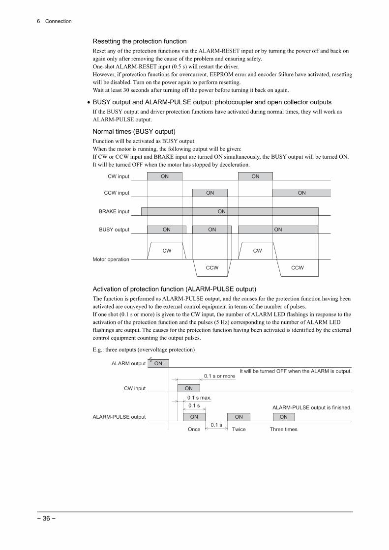
6 Connection
− 36 −
Resetting the protection function Reset any of the protection functions via the ALARM-RESET input or by turning the power off and back on again only after removing the cause of the problem and ensuring safety. One-shot ALARM-RESET input (0.5 s) will restart the driver. However, if protection functions for overcurrent, EEPROM error and encoder failure have activated, resetting will be disabled. Turn on the power again to perform resetting. Wait at least 30 seconds after turning off the power before turning it back on again.
• BUSY output and ALARM-PULSE output: photocoupler and open collector outputs If the BUSY output and driver protection functions have activated during normal times, they will work as ALARM-PULSE output.
Normal times (BUSY output) Function will be activated as BUSY output. When the motor is running, the following output will be given: If CW or CCW input and BRAKE input are turned ON simultaneously, the BUSY output will be turned ON. It will be turned OFF when the motor has stopped by deceleration.
CW CW
CW input
BRAKE input
CCW input
Motor operation
ON
CCW CCW
ON
ON
BUSY output ON ON ON
ON ON
Activation of protection function (ALARM-PULSE output) The function is performed as ALARM-PULSE output, and the causes for the protection function having been activated are conveyed to the external control equipment in terms of the number of pulses. If one shot (0.1 s or more) is given to the CW input, the number of ALARM LED flashings in response to the activation of the protection function and the pulses (5 Hz) corresponding to the number of ALARM LED flashings are output. The causes for the protection function having been activated is identified by the external control equipment counting the output pulses.
E.g.: three outputs (overvoltage protection)
ALARM output
CW input
ON
ON
ALARM-PULSE output ON ON ON
0.1 s or more
0.1 sOnce Twice Three times
0.1 s0.1 s max.
It will be turned OFF when the ALARM is output.
ALARM-PULSE output is finished.
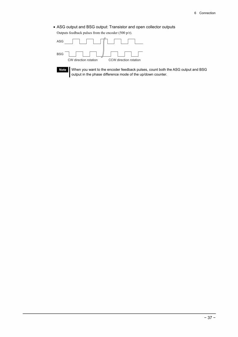
6 Connection
− 37 −
• ASG output and BSG output: Transistor and open collector outputs Outputs feedback pulses from the encoder (500 p/r).
ASG
CW direction rotation
BSG
CCW direction rotation
Note When you want to the encoder feedback pulses, count both the ASG output and BSG output in the phase difference mode of the up/down counter.

7 Running
− 38 −
7 Running Setting the motor running speed and running operation are as follows.
7.1 Rotating direction of the motor output shaft The rotating direction of the motor output shaft is defined as clockwise (CW) or counterclockwise (CCW) as viewed from the motor output shaft. However, the rotating direction of the motor output shaft may vary from that of the gearhead output shaft depending on the gear ratio of the gearhead.
When the CCW input is ON
When the CW input is ON
Rotating direction of the gearhead output shaft
• Combination-type parallel-shaft gearhead Gear ratios 5, 10, 15, 20, 200 : Same direction as the motor Gear ratios 30, 50, 100 : Opposite direction to the motor
When the CW input is ON∗
When the CCW input is ON∗
∗ The rotating direction when the CW input or CCW input is ON varies depending on the gear ratio.
• Combination-type hollow-shaft flat gearhead At all gear ratios, the rotating direction is opposite to that of the motor as viewed from the front. With a combination-type hollow-shaft flat gearhead, the rotating direction will vary depending on whether the motor unit is viewed from the front or rear.
When the CW input is ON When the CCW
input is ON
When the CW input is ONWhen the CCW
input is ON
• Viewed from Front • Viewed from Rear
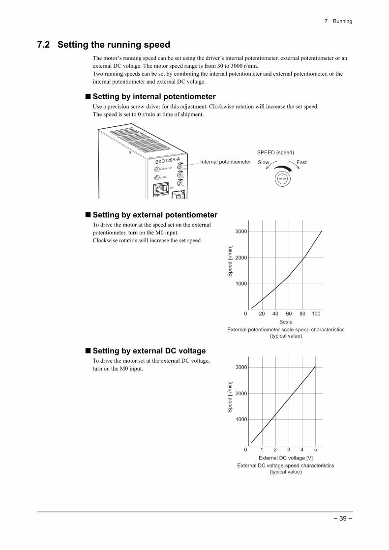
7 Running
− 39 −
7.2 Setting the running speed The motor’s running speed can be set using the driver’s internal potentiometer, external potentiometer or an external DC voltage. The motor speed range is from 30 to 3000 r/min. Two running speeds can be set by combining the internal potentiometer and external potentiometer, or the internal potentiometer and external DC voltage.
Setting by internal potentiometer Use a precision screw-driver for this adjustment. Clockwise rotation will increase the set speed. The speed is set to 0 r/min at time of shipment.
Internal potentiometer Fast
SPEED (speed)
Slow
Setting by external potentiometer To drive the motor at the speed set on the external potentiometer, turn on the M0 input. Clockwise rotation will increase the set speed.
3000
2000
1000
0 20 40 60 80 100
Spe
ed [r
/min
]
ScaleExternal potentiometer scale-speed characteristics
(typical value)
Setting by external DC voltage To drive the motor set at the external DC voltage, turn on the M0 input. 3000
2000
1000
0 1 2 3 4 5
Spe
ed [r
/min
]
External DC voltage [V]External DC voltage-speed characteristics
(typical value)
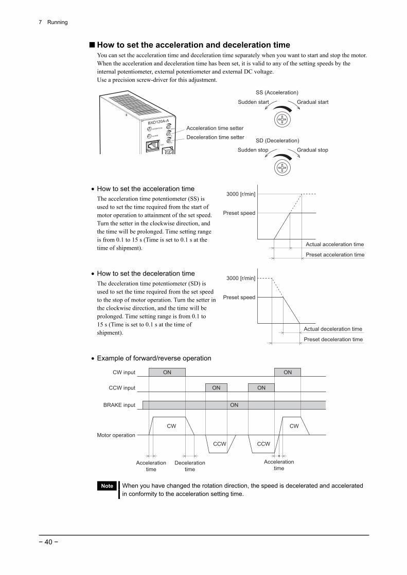
7 Running
− 40 −
How to set the acceleration and deceleration time You can set the acceleration time and deceleration time separately when you want to start and stop the motor. When the acceleration and deceleration time has been set, it is valid to any of the setting speeds by the internal potentiometer, external potentiometer and external DC voltage. Use a precision screw-driver for this adjustment.
Acceleration time setter
Deceleration time setter
Gradual stopSudden stop
SD (Deceleration)
Gradual startSudden start
SS (Acceleration)
• How to set the acceleration time The acceleration time potentiometer (SS) is used to set the time required from the start of motor operation to attainment of the set speed. Turn the setter in the clockwise direction, and the time will be prolonged. Time setting range is from 0.1 to 15 s (Time is set to 0.1 s at the time of shipment).
3000 [r/min]
Actual acceleration time
Preset speed
Preset acceleration time
• How to set the deceleration time The deceleration time potentiometer (SD) is used to set the time required from the set speed to the stop of motor operation. Turn the setter in the clockwise direction, and the time will be prolonged. Time setting range is from 0.1 to 15 s (Time is set to 0.1 s at the time of shipment).
3000 [r/min]
Actual deceleration time
Preset speed
Preset deceleration time
• Example of forward/reverse operation
CW CW
Accelerationtime
CW input
BRAKE input
CCW input
Motor operation
ON ON
CCW CCW
ON ON
ON
Decelerationtime
Accelerationtime
Note When you have changed the rotation direction, the speed is decelerated and accelerated in conformity to the acceleration setting time.
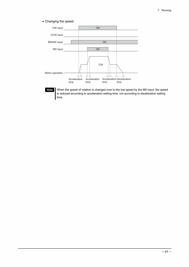
7 Running
− 41 −
• Changing the speed
CCW input
M0 input
BRAKE input
Motor operation
ON
ON
CW input
CW
ON
Decelerationtime
Accelerationtime
Accelerationtime
Accelerationtime
Note When the speed of rotation is changed over to the low speed by the M0 input, the speed is reduced according to acceleration setting time, not according to deceleration setting time.
8 Inspection
− 42 −
8 Inspection It is recommended to check the following four items after motor operation. If any failure is found, stop the operation, and please contact your local sales office.
8.1 Inspection items • Check if the motor and gearhead installation screws are loosened or not. • Check if abnormal noise is produced from the motor bearing section (ball bearing). • Check if abnormal noise is produced from the gearhead bearing (ball bearing) and gear meshing section. • Check if the motor/gearhead output shaft and load shaft are misaligned or not. • Check if the motor cable or encoder cable are damaged or stressed. Also check if the connections with the
driver are loosened. • Check if the driver opening is clogged or not. • Check if the driver mounting screws and power connection terminal screws are loosened or not. • Check if the driver internal power element smoothing capacitor have abnormal smell or other failures.
Note • To prevent the encoder from being damaged, never measure the insulation resistance or dielectric strength of the encoder as an independent unit.
• Semiconducting elements are used for the driver. Carefully handle the driver, because the driver may be damaged by static electricity.
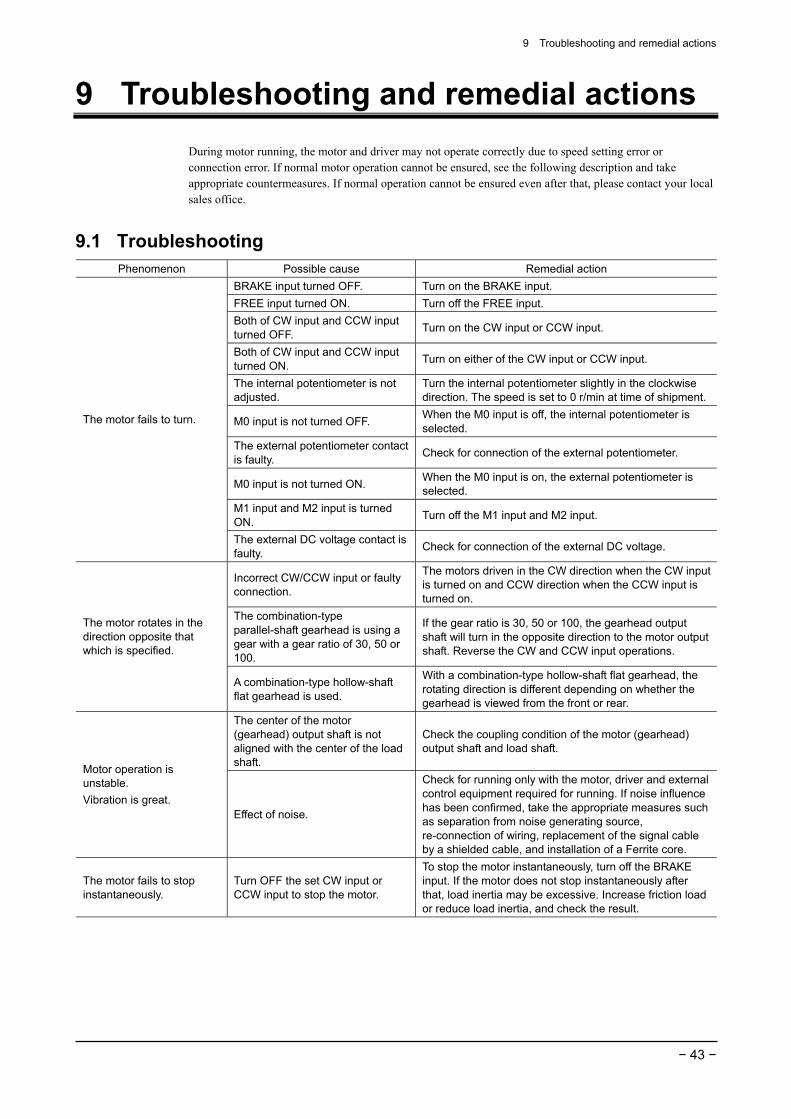
9 Troubleshooting and remedial actions
− 43 −
9 Troubleshooting and remedial actions During motor running, the motor and driver may not operate correctly due to speed setting error or connection error. If normal motor operation cannot be ensured, see the following description and take appropriate countermeasures. If normal operation cannot be ensured even after that, please contact your local sales office.
9.1 Troubleshooting Phenomenon Possible cause Remedial action
BRAKE input turned OFF. Turn on the BRAKE input. FREE input turned ON. Turn off the FREE input. Both of CW input and CCW input turned OFF. Turn on the CW input or CCW input.
Both of CW input and CCW input turned ON. Turn on either of the CW input or CCW input.
The internal potentiometer is not adjusted.
Turn the internal potentiometer slightly in the clockwise direction. The speed is set to 0 r/min at time of shipment.
M0 input is not turned OFF. When the M0 input is off, the internal potentiometer is selected.
The external potentiometer contact is faulty. Check for connection of the external potentiometer.
M0 input is not turned ON. When the M0 input is on, the external potentiometer is selected.
M1 input and M2 input is turned ON. Turn off the M1 input and M2 input.
The motor fails to turn.
The external DC voltage contact is faulty. Check for connection of the external DC voltage.
Incorrect CW/CCW input or faulty connection.
The motors driven in the CW direction when the CW input is turned on and CCW direction when the CCW input is turned on.
The combination-type parallel-shaft gearhead is using a gear with a gear ratio of 30, 50 or 100.
If the gear ratio is 30, 50 or 100, the gearhead output shaft will turn in the opposite direction to the motor output shaft. Reverse the CW and CCW input operations.
The motor rotates in the direction opposite that which is specified.
A combination-type hollow-shaft flat gearhead is used.
With a combination-type hollow-shaft flat gearhead, the rotating direction is different depending on whether the gearhead is viewed from the front or rear.
The center of the motor (gearhead) output shaft is not aligned with the center of the load shaft.
Check the coupling condition of the motor (gearhead) output shaft and load shaft.
Motor operation is unstable. Vibration is great.
Effect of noise.
Check for running only with the motor, driver and external control equipment required for running. If noise influence has been confirmed, take the appropriate measures such as separation from noise generating source, re-connection of wiring, replacement of the signal cable by a shielded cable, and installation of a Ferrite core.
The motor fails to stop instantaneously.
Turn OFF the set CW input or CCW input to stop the motor.
To stop the motor instantaneously, turn off the BRAKE input. If the motor does not stop instantaneously after that, load inertia may be excessive. Increase friction load or reduce load inertia, and check the result.
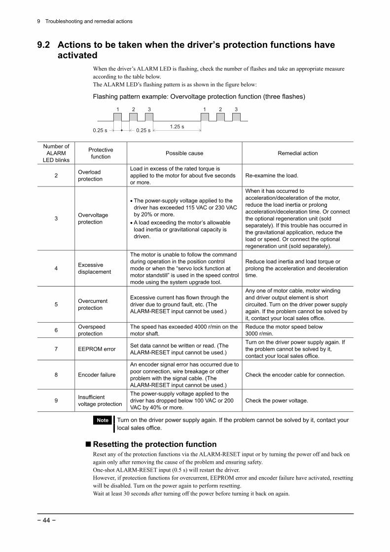
9 Troubleshooting and remedial actions
− 44 −
9.2 Actions to be taken when the driver’s protection functions have activated
When the driver’s ALARM LED is flashing, check the number of flashes and take an appropriate measure according to the table below. The ALARM LED’s flashing pattern is as shown in the figure below:
Flashing pattern example: Overvoltage protection function (three flashes)
1 2 3 1 2 3
1.25 s0.25 s 0.25 s
Number of ALARM
LED blinks
Protective function Possible cause Remedial action
2 Overload protection
Load in excess of the rated torque is applied to the motor for about five seconds or more.
Re-examine the load.
3 Overvoltage protection
• The power-supply voltage applied to the driver has exceeded 115 VAC or 230 VAC by 20% or more.
• A load exceeding the motor’s allowable load inertia or gravitational capacity is driven.
When it has occurred to acceleration/deceleration of the motor, reduce the load inertia or prolong acceleration/deceleration time. Or connect the optional regeneration unit (sold separately). If this trouble has occurred in the gravitational application, reduce the load or speed. Or connect the optional regeneration unit (sold separately).
4 Excessive displacement
The motor is unable to follow the command during operation in the position control mode or when the “servo lock function at motor standstill” is used in the speed control mode using the system upgrade tool.
Reduce load inertia and load torque or prolong the acceleration and deceleration time.
5 Overcurrent protection
Excessive current has flown through the driver due to ground fault, etc. (The ALARM-RESET input cannot be used.)
Any one of motor cable, motor winding and driver output element is short circuited. Turn on the driver power supply again. If the problem cannot be solved by it, contact your local sales office.
6 Overspeed protection
The speed has exceeded 4000 r/min on the motor shaft.
Reduce the motor speed below 3000 r/min.
7 EEPROM error Set data cannot be written or read. (The ALARM-RESET input cannot be used.)
Turn on the driver power supply again. If the problem cannot be solved by it, contact your local sales office.
8 Encoder failure
An encoder signal error has occurred due to poor connection, wire breakage or other problem with the signal cable. (The ALARM-RESET input cannot be used.)
Check the encoder cable for connection.
9 Insufficient voltage protection
The power-supply voltage applied to the driver has dropped below 100 VAC or 200 VAC by 40% or more.
Check the power voltage.
Note Turn on the driver power supply again. If the problem cannot be solved by it, contact your local sales office.
Resetting the protection function Reset any of the protection functions via the ALARM-RESET input or by turning the power off and back on again only after removing the cause of the problem and ensuring safety. One-shot ALARM-RESET input (0.5 s) will restart the driver. However, if protection functions for overcurrent, EEPROM error and encoder failure have activated, resetting will be disabled. Turn on the power again to perform resetting. Wait at least 30 seconds after turning off the power before turning it back on again.
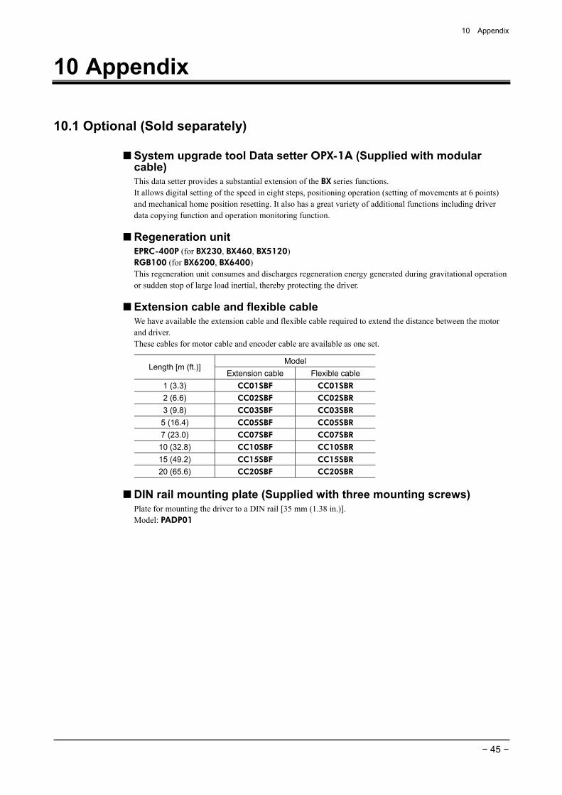
10 Appendix
− 45 −
10 Appendix
10.1 Optional (Sold separately)
System upgrade tool Data setter OPX-1A (Supplied with modular cable) This data setter provides a substantial extension of the BX series functions. It allows digital setting of the speed in eight steps, positioning operation (setting of movements at 6 points) and mechanical home position resetting. It also has a great variety of additional functions including driver data copying function and operation monitoring function.
Regeneration unit EPRC-400P (for BX230, BX460, BX5120) RGB100 (for BX6200, BX6400) This regeneration unit consumes and discharges regeneration energy generated during gravitational operation or sudden stop of large load inertial, thereby protecting the driver.
Extension cable and flexible cable We have available the extension cable and flexible cable required to extend the distance between the motor and driver. These cables for motor cable and encoder cable are available as one set.
Model Length [m (ft.)]
Extension cable Flexible cable 1 (3.3) CC01SBF CC01SBR
2 (6.6) CC02SBF CC02SBR
3 (9.8) CC03SBF CC03SBR
5 (16.4) CC05SBF CC05SBR
7 (23.0) CC07SBF CC07SBR
10 (32.8) CC10SBF CC10SBR
15 (49.2) CC15SBF CC15SBR
20 (65.6) CC20SBF CC20SBR
DIN rail mounting plate (Supplied with three mounting screws) Plate for mounting the driver to a DIN rail [35 mm (1.38 in.)]. Model: PADP01
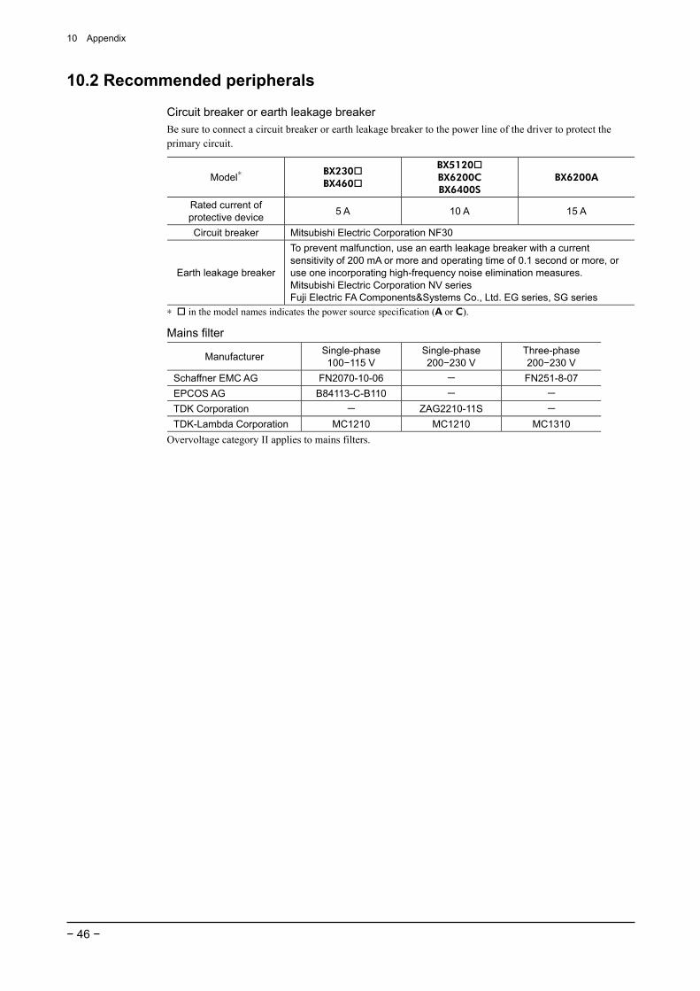
10 Appendix
− 46 −
10.2 Recommended peripherals
Circuit breaker or earth leakage breaker Be sure to connect a circuit breaker or earth leakage breaker to the power line of the driver to protect the primary circuit.
Model∗ BX230 BX460
BX5120 BX6200C BX6400S
BX6200A
Rated current of protective device 5 A 10 A 15 A
Circuit breaker Mitsubishi Electric Corporation NF30
Earth leakage breaker
To prevent malfunction, use an earth leakage breaker with a current sensitivity of 200 mA or more and operating time of 0.1 second or more, or use one incorporating high-frequency noise elimination measures. Mitsubishi Electric Corporation NV series Fuji Electric FA Components&Systems Co., Ltd. EG series, SG series
∗ in the model names indicates the power source specification (A or C).
Mains filter
Manufacturer Single-phase 100−115 V
Single-phase 200−230 V
Three-phase 200−230 V
Schaffner EMC AG FN2070-10-06 - FN251-8-07 EPCOS AG B84113-C-B110 - - TDK Corporation - ZAG2210-11S - TDK-Lambda Corporation MC1210 MC1210 MC1310
Overvoltage category II applies to mains filters.


• Unauthorized reproduction or copying of all or part of this manual is prohibited. If a new copy is required to replace an original manual that has been damaged or lost, please contact your nearest Oriental Motor branch or sales office.
• Oriental Motor shall not be liable whatsoever for any problems relating to industrial property rights arising from use of any information, circuit, equipment or device provided or referenced in this manual.
• Characteristics, specifications and dimensions are subject to change without notice. • While we make every effort to offer accurate information in the manual, we welcome your input. Should you find unclear
descriptions, errors or omissions, please contact the nearest office. • is a registered trademark or trademark of Oriental Motor Co., Ltd., in Japan and other countries.
Other product names and company names mentioned in this manual may be registered trademarks or trademarks of their respective companies and are hereby acknowledged. The third-party products mentioned in this manual are recommended products, and references to their names shall not be construed as any form of performance guarantee. Oriental Motor is not liable whatsoever for the performance of these third-party products.
© Copyright ORIENTAL MOTOR CO., LTD. 2010
Printed on Recycled Paper
• Please contact your nearest Oriental Motor office for further information.
Technical Support Tel:(800)468-39828:30 A.M. to 5:00 P.M., P.S.T. (M-F)7:30 A.M. to 5:00 P.M., C.S.T. (M-F)E-mail: [email protected]
Headquarters and Düsseldorf OfficeTel:0211-52067-00 Fax:0211-52067-099Munich Office Tel:089-3181225-00 Fax:089-3181225-25Hamburg OfficeTel:040-76910443 Fax:040-76910445
Tel:01256-347090 Fax:01256-347099
Tel:01 47 86 97 50 Fax:01 47 82 45 16
Tel:02-93906346 Fax:02-93906348
Tel:(02)8228-0707 Fax:(02)8228-0708
Tel:+65-6745-7344 Fax:+65-6745-9405
Tel:(03)22875778 Fax:(03)22875528
KOREATel:080-777-2042 Fax:02-2026-5495
Headquarters Tokyo, JapanTel:03-6744-0361 Fax:03-5826-2576
Tel:+66-2-251-1871 Fax:+66-2-251-1872
Tel:400-820-6516 Fax:021-6278-0269