Brushless DC Motor and Driver Package BLH Series · HM-5063-3 Brushless DC Motor and Driver Package...
52
HM-5063-3 Brushless DC Motor and Driver Package BLH Series OPERATING MANUAL Thank you for purchasing an Oriental Motor product. This Operating Manual describes product handling procedures and safety precautions. • Please read it thoroughly to ensure safe operation. • Always keep the manual where it is readily available. Table of contents 1 Introduction .................................. 2 1.1 Before using the motor unit ......... 2 1.2 Overview of the product .............. 2 1.3 Standards and CE Marking ......... 2 1.4 Hazardous substances ............... 3 2 Safety precautions ....................... 4 3 Precautions for use ...................... 7 4 Preparation................................... 8 4.1 Checking the product .................. 8 4.2 Combination tables ..................... 9 4.3 Names and function of parts ..... 11 5 Installation .................................. 12 5.1 Installation location ................... 12 5.2 Installing the geared type, combination type parallel shaft gearhead ................................... 13 5.3 Installing the combination type hollow shaft flat gearhead ......... 15 5.4 Installing the round shaft type ... 18 5.5 Installing the pinion shaft type... 19 5.6 Installing a load on the geared type, combination type parallel shaft gearhead and round shaft type .. 19 5.7 Installing a load on the combination type hollow shaft flat gearhead... 22 5.8 Driver installation ...................... 23 5.9 Installing and wiring in compliance with EMC Directive ................... 24 6 Connection ..................................28 6.1 Motor and driver connection ..... 28 6.2 Connecting the power supply ... 28 6.3 Connection of input signal and output signal ............................. 29 6.4 Driver I/O circuit and example connection ................................ 31 7 Operation ....................................32 7.1 Input signals and output signals.. 32 7.2 Rotating direction of the motor output shaft ............................... 39 7.3 Setting the running speed ........ 40 7.4 Setting the acceleration time and deceleration time ...................... 43 7.5 Parallel operation ..................... 44 8 Inspection....................................46 9 Troubleshooting and remedial actions ........................................47 10 Appendix .....................................50 10.1 Options (sold separately) ......... 50 10.2 Recommended peripherals ...... 51
Transcript of Brushless DC Motor and Driver Package BLH Series · HM-5063-3 Brushless DC Motor and Driver Package...

HM-5063-3
Brushless DC Motor and Driver Package
BLH Series
OPERATING MANUAL
Thank you for purchasing an Oriental Motor product. This Operating Manual describes product handling procedures and safety precautions. • Please read it thoroughly to ensure safe operation. • Always keep the manual where it is readily available.
Table of contents 1 Introduction .................................. 2
1.1 Before using the motor unit.........2 1.2 Overview of the product ..............2 1.3 Standards and CE Marking .........2 1.4 Hazardous substances ...............3
2 Safety precautions ....................... 4 3 Precautions for use ...................... 7 4 Preparation................................... 8
4.1 Checking the product ..................8 4.2 Combination tables .....................9 4.3 Names and function of parts ..... 11
5 Installation .................................. 12 5.1 Installation location ...................12 5.2 Installing the geared type,
combination type parallel shaft gearhead...................................13
5.3 Installing the combination type hollow shaft flat gearhead .........15
5.4 Installing the round shaft type ...18 5.5 Installing the pinion shaft type...19 5.6 Installing a load on the geared type,
combination type parallel shaft gearhead and round shaft type ..19
5.7 Installing a load on the combination type hollow shaft flat gearhead...22
5.8 Driver installation ......................23
5.9 Installing and wiring in compliance with EMC Directive ................... 24
6 Connection..................................28 6.1 Motor and driver connection..... 28 6.2 Connecting the power supply ... 28 6.3 Connection of input signal and
output signal ............................. 29 6.4 Driver I/O circuit and example
connection ................................ 31 7 Operation ....................................32
7.1 Input signals and output signals.. 32 7.2 Rotating direction of the motor
output shaft............................... 39 7.3 Setting the running speed ........ 40 7.4 Setting the acceleration time and
deceleration time ...................... 43 7.5 Parallel operation ..................... 44
8 Inspection....................................46 9 Troubleshooting and remedial
actions ........................................47 10 Appendix .....................................50
10.1 Options (sold separately) ......... 50 10.2 Recommended peripherals ...... 51
1 Introduction
-2-
1 Introduction
1.1 Before using the motor unit This product is designed to be incorporated into general industrial machinery, and must not be used for other purposes. For the power supply use a DC power supply with reinforced insulation on its primary and secondary sides. It should be noted that we are not responsible for any damages caused by ignoring this warning.
1.2 Overview of the product The BLH series is a brushless DC motor unit that adopts a slim, high-torque brushless DC motor and an open-case high-precision compact driver of 24 VDC input type. The product is available in three types; a round shaft type which is the optimum for high speed requirements and a combination type* equipped with a special-purpose gearhead which is best suited to high-torque operation by gear speed reduction (a pinion shaft type* compatible with optional special-purpose gearhead). ∗ The motor with a frame size of 42 mm (1.65 in.) is a geared type. There is no pinion shaft
type available.
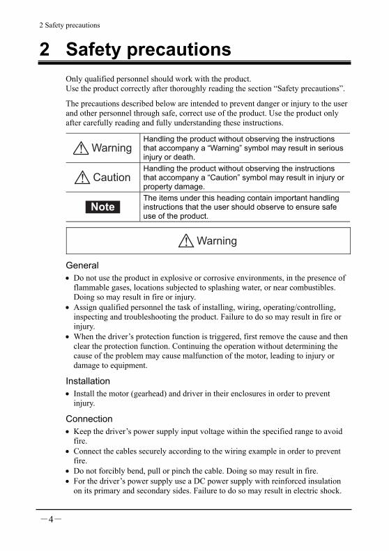
1.3 Standards and CE Marking This product is recognized by UL and certified by CSA, and bears the CE Marking (EMC Directive) in compliance with the EN Standards.
Applicable Standards Certification Body
Standard File No.
BLH015 BLH230 BLH450 BLH5100
UL 60950-1 CSA C22.2 No.60950-1 UL E208200
The names of products certified to conform with relevant standards are represented by applicable unit model motor and driver part numbers.
Installation conditions • The product is to be used as a component within other equipment. • Overvoltage category: I • Pollution degree: 2 • Protection against electric shock: Class III equipment
1 Introduction
-3-
For Low Voltage Directive • Since this product is based on 24 VDC power supply input, it is outside the
application scope of Low Voltage Directives. • When applying the equipment incorporating this product to the Low Voltage
Directive, connect the driver power supply input to the DC power supply where the primary and secondary sides are provided with reinforced insulation.
• Install this product in the equipment built-in type enclosure. • Enclosure classification
Motor: IP65 (Lead wire type: IP40) Driver: IP00
For EMC Directive (89/336/EEC, 92/31/EEC) This product has received EMC measures under the conditions specified in “Example of motor and driver installation and wiring” on page 27. Be sure to conduct EMC measures with the product assembled in your equipment by referring to 5.9 “Installing and wiring in compliance with EMC Directive” on page 24.
1.4 Hazardous substances RoHS (Directive 2002/95/EC 27Jan.2003) compliant
2 Safety precautions
-4-
2 Safety precautions Only qualified personnel should work with the product. Use the product correctly after thoroughly reading the section “Safety precautions”.
The precautions described below are intended to prevent danger or injury to the user and other personnel through safe, correct use of the product. Use the product only after carefully reading and fully understanding these instructions.
WarningHandling the product without observing the instructions that accompany a “Warning” symbol may result in serious injury or death.
Caution
Handling the product without observing the instructions that accompany a “Caution” symbol may result in injury or property damage.
Note
The items under this heading contain important handling instructions that the user should observe to ensure safe use of the product.
Warning
General • Do not use the product in explosive or corrosive environments, in the presence of
flammable gases, locations subjected to splashing water, or near combustibles. Doing so may result in fire or injury.
• Assign qualified personnel the task of installing, wiring, operating/controlling, inspecting and troubleshooting the product. Failure to do so may result in fire or injury.
• When the driver’s protection function is triggered, first remove the cause and then clear the protection function. Continuing the operation without determining the cause of the problem may cause malfunction of the motor, leading to injury or damage to equipment.
Installation • Install the motor (gearhead) and driver in their enclosures in order to prevent
injury.
Connection • Keep the driver’s power supply input voltage within the specified range to avoid
fire. • Connect the cables securely according to the wiring example in order to prevent
fire. • Do not forcibly bend, pull or pinch the cable. Doing so may result in fire. • For the driver’s power supply use a DC power supply with reinforced insulation
on its primary and secondary sides. Failure to do so may result in electric shock.

2 Safety precautions
-5-
Operation • Turn off the driver power supply in the event of a power failure, or the motor may
suddenly start when the power is restored and may cause injury or damage to equipment.
• Do not use it in a vertical applications. When the driver protection function is triggered, the motor will stop operating. The moving parts fall and may cause injury or damage to equipment.
Repair, disassembly and modification • Do not disassemble or modify the motor, gearhead or driver. This may cause
injury. Refer all such internal inspections and repairs to the branch or sales office from which you purchased the product.
Caution
General • Do not use the motor, gearhead and driver beyond their specifications, or injury or
damage to equipment may result. • Do not touch the motor or driver during operation or immediately after stopping.
The surfaces are hot and may cause a burn.
Transportation • Do not hold the motor (gearhead) output shaft or motor cable. This may cause
injury.
Installation • Keep the area around the motor and driver free of combustible materials in order
to prevent fire or a burn. • To prevent the risk of damage to equipment, leave nothing around the motor and
driver that would obstruct ventilation. • Provide a cover over the rotating parts (output shaft) of the motor (gearhead) to
prevent injury.

2 Safety precautions
-6-
Operation • Use a motor and driver only in the specified combination. An incorrect
combination may cause a fire. • Provide an emergency-stop device or emergency-stop circuit external to the
equipment so that the entire equipment will operate safely in the event of a system failure or malfunction. Failure to do so may result in injury.
• Immediately when trouble has occurred, stop running and turn off the driver power supply. Failure to do so may result in fire, electric shock or injury.
• Provide a cover over the rotating parts (output shaft) of the motor to prevent injury.
• Release all driver input signals before turning on the power supply to the driver. Otherwise, the motor may start suddenly and cause injury or damage to equipment.
• Before moving the motor directly with the hands (as in the case of manual positioning), confirm that the driver operation input is “OFF” to prevent injury.
• Do not perform the motor’s starting and stopping operations by turning the power supply on and off. Perform them by inputting START/STOP and RUN/BRAKE. This may cause injury or damage to the equipment.
• The motor’s surface temperature may exceed 70°C, even under normal operating conditions. If a motor is accessible during operation, post a warning label shown in the figure in a conspicuous position to prevent the risk of burns.
Warning label
Disposal • To dispose of the motor, gearhead and driver disassemble it into parts and
components as much as possible and dispose of individual parts/components as industrial waste.
3 Precautions for use
-7-
3 Precautions for use This chapter explains the restrictions and other items you should take heed of when using the BLH series.
Do not perform gravitational load operation With the BLH series, any operation in which the motor output shaft is turned from the load side (gravitational load operation) will disable the motor speed control. In addition, a gravitational load operation will cause the driver’s primary inverter voltage to exceed the allowable value, thereby triggering a protection function and causing the motor to stop spontaneously. If this happens, there is a possibility that the load will drop.
Grease measures On rare occasions a small amount of grease may leak from the gearhead. If leaked grease is feared to contaminate the surrounding environment, check for grease leakage during regular inspections or provide an oil pan or other device to prevent damage resulting from contamination. Leaking oil is a cause of malfunction in your equipment or product.
Apply grease on the output shaft of the hollow shaft flat gearhead If you are using a gearhead, apply grease (molybdenum disulfide grease, etc.) on the surface of the load shaft and inner walls of the hollow output shaft to prevent seizure.
Conduct the insulation resistance measurement or withstand voltage test separately on the motor and the driver Conducting the insulation resistance measurement or withstand voltage test with the motor and driver connected may result in injury or damage to equipment.
Noise elimination measures Provide the following noise elimination measures to prevent a motor or driver malfunction caused by external noise.
Wiring the motor To extend the wiring between the motor and driver, use the optional extension cable (sold separately).
Wiring the I/O signals cable • Minimize the wiring length of the I/O signals cable. • Provide a minimum clearance of 100 mm (4 in.) between the I/O signals cable and
any inductive load such as an electromagnetic relay or any power line (power supply, motor, etc.). Do not place the I/O signals cable and a power line in the same duct or pipe or bundle them together.
• For more effective elimination of noise, use a shielded I/O signals cable or attach ferrite cores if a non-shielded cable is used.

4 Preparation
-8-
4 Preparation The following describes the items to be confirmed, names and functions of individual components.
4.1 Checking the product Open the package and make sure that the following items are supplied. The supplied items vary depending on the product. If there is any shortage or damage, contact the sales office where you bought the product.
The unit model of the product you bought should be checked by reference to the model on the label of the package. Check the models of the motor, gearhead and driver by reference to the models on the name plate of each product. The table on page 9, 10 shows the combination of the motor, gearhead and driver according to unit models.
Geared type, round shaft type and pinion shaft type • Motor 1 unit (Geared type is motor with gearhead) • Driver 1unit • I/O signals cable [300 mm (12 in.)] 1 pc. • Power supply cable [300 mm (12 in.)] 1 pc. • Operating manual (This manual) 1 copy
Combination type parallel shaft gearhead • Motor with gearhead 1 unit • Parallel key 1 pc. • Driver 1unit • I/O signals cable [300 mm (12 in.)] 1 pc. • Power supply cable [300 mm (12 in.)] 1 pc. • Hexagonal socket head screw set
(four each of screws, washers and nuts) 1 set • Operating manual (This manual) 1 copy
4 Preparation
-9-
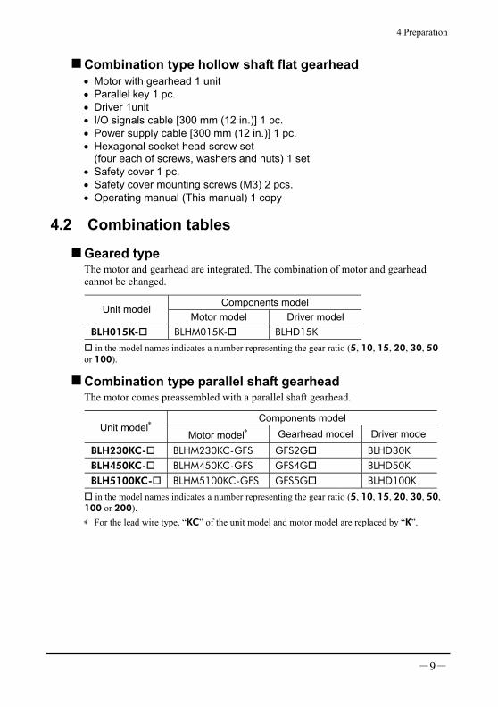
Combination type hollow shaft flat gearhead • Motor with gearhead 1 unit • Parallel key 1 pc. • Driver 1unit • I/O signals cable [300 mm (12 in.)] 1 pc. • Power supply cable [300 mm (12 in.)] 1 pc. • Hexagonal socket head screw set
(four each of screws, washers and nuts) 1 set • Safety cover 1 pc. • Safety cover mounting screws (M3) 2 pcs. • Operating manual (This manual) 1 copy
4.2 Combination tables
Geared type The motor and gearhead are integrated. The combination of motor and gearhead cannot be changed.
Components model Unit model
Motor model Driver model BLH015K- BLHM015K- BLHD15K
in the model names indicates a number representing the gear ratio (5, 10, 15, 20, 30, 50 or 100).
Combination type parallel shaft gearhead The motor comes preassembled with a parallel shaft gearhead.
Components model Unit model∗
Motor model∗ Gearhead model Driver modelBLH230KC- BLHM230KC-GFS GFS2G BLHD30K BLH450KC- BLHM450KC-GFS GFS4G BLHD50K BLH5100KC- BLHM5100KC-GFS GFS5G BLHD100K
in the model names indicates a number representing the gear ratio (5, 10, 15, 20, 30, 50, 100 or 200). ∗ For the lead wire type, “KC” of the unit model and motor model are replaced by “K”.
4 Preparation
-10-
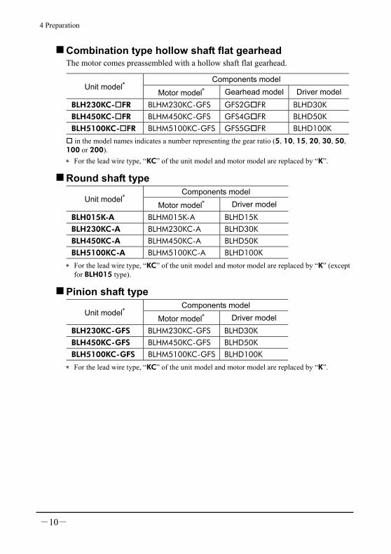
Combination type hollow shaft flat gearhead The motor comes preassembled with a hollow shaft flat gearhead.
Components model Unit model∗
Motor model∗ Gearhead model Driver modelBLH230KC- FR BLHM230KC-GFS GFS2G FR BLHD30K BLH450KC- FR BLHM450KC-GFS GFS4G FR BLHD50K BLH5100KC- FR BLHM5100KC-GFS GFS5G FR BLHD100K
in the model names indicates a number representing the gear ratio (5, 10, 15, 20, 30, 50, 100 or 200). ∗ For the lead wire type, “KC” of the unit model and motor model are replaced by “K”.
Round shaft type Components model
Unit model∗ Motor model∗ Driver model
BLH015K-A BLHM015K-A BLHD15K BLH230KC-A BLHM230KC-A BLHD30K BLH450KC-A BLHM450KC-A BLHD50K BLH5100KC-A BLHM5100KC-A BLHD100K
∗ For the lead wire type, “KC” of the unit model and motor model are replaced by “K” (except for BLH015 type).
Pinion shaft type Components model
Unit model∗ Motor model∗ Driver model
BLH230KC-GFS BLHM230KC-GFS BLHD30K BLH450KC-GFS BLHM450KC-GFS BLHD50K BLH5100KC-GFS BLHM5100KC-GFS BLHD100K
∗ For the lead wire type, “KC” of the unit model and motor model are replaced by “K”.
4 Preparation
-11-
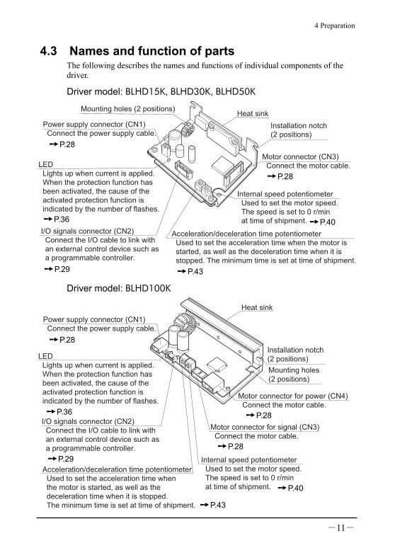
4.3 Names and function of parts The following describes the names and functions of individual components of the driver.
Driver model: BLHD15K, BLHD30K, BLHD50K
Motor connector (CN3) Connect the motor cable.LED
Lights up when current is applied. When the protection function has been activated, the cause of the activated protection function is indicated by the number of flashes.
Power supply connector (CN1) Connect the power supply cable.
Mounting holes (2 positions)
Installation notch (2 positions)
I/O signals connector (CN2) Connect the I/O cable to link with an external control device such as a programmable controller.
Internal speed potentiometer Used to set the motor speed. The speed is set to 0 r/min at time of shipment.
Acceleration/deceleration time potentiometer Used to set the acceleration time when the motor is started, as well as the deceleration time when it is stopped. The minimum time is set at time of shipment.
Heat sink
Driver model: BLHD100K
Installation notch(2 positions)
Mounting holes(2 positions)
Motor connector for power (CN4) Connect the motor cable.
Motor connector for signal (CN3) Connect the motor cable.
Internal speed potentiometer Used to set the motor speed. The speed is set to 0 r/min at time of shipment.
I/O signals connector (CN2) Connect the I/O cable to link with an external control device such as a programmable controller.
LED Lights up when current is applied. When the protection function has been activated, the cause of the activated protection function is indicated by the number of flashes.
Power supply connector (CN1) Connect the power supply cable.
Acceleration/deceleration time potentiometer Used to set the acceleration time when the motor is started, as well as the deceleration time when it is stopped. The minimum time is set at time of shipment.
Heat sink
P.28
P.28
P.29
P.36 P.40
P.43
P.28
P.36
P.29
P.43
P.28
P.28
P.40

5 Installation
-12-
5 Installation This chapter explains the installation location and installation methods of the motor and driver, as well as how to install a load. Read the applicable sections carefully to install each item correctly.
Geared type Combination type parallel shaft gearhead
P.13, 19
Combination type hollow shaft flatgearhead P.15, 22
Round shaft type P.18, 19
Pinion shaft type Parallel shaft gearhead: P.13, 19 Hollow shaft flat gearhead: P.15, 22
5.1 Installation location The motor and driver are designed and manufactured for use as internal components of equipment. Install the motor and driver in a well-ventilated place where they can be inspected easily and the following conditions are satisfied: • Inside an enclosure that is installed indoors (provide vent holes) • Operating ambient temperature: 0 to +50°C (+32 to +122°F) (non-freezing) • Operating ambient humidity: 85% or less (non-condensing) • Area that is free of explosive atmosphere or toxic gas (such as sulfuric gas) or
liquid • Area not exposed to direct sun • Area free of excessive amount of dust, iron particles or the like • Area not subject to splashing water (rains, water droplets), oil (oil droplets) or
other liquids • Area free of excessive salt • Area not subject to continuous vibration or excessive shocks • Area free of excessive electromagnetic noise (from welders, power machinery,
etc.) • Area free of radioactive materials, magnetic fields or vacuum
Install the motor to a flat mounting plate offering excellent vibration resistance and high heat conductivity.

5 Installation
-13-
5.2 Installing the geared type, combination type parallel shaft gearhead
1. Open mounting holes in the mounting plate. [Unit: mm (in.)]
Unit model ØA ØB C ØD
BLH015 43.8(1.72)
16 (0.63)
8 (0.31)
4.5 (0.177)
BLH230 70 (2.76)
24 (0.94)
10 (0.39)
4.5 (0.177)
BLH450 94 (3.70)
34 (1.34)
13 (0.51)
6.5 (0.256)
ØB
C
4×ØD
ØA
BLH5100 104 (4.09)
40 (1.57)
18 (0.71)
8.5 (0.335)
ØB indicates the external dimension of the product. Provide a hole with a diameter of “ØB +1 mm or more.”
Maximum applicable plate thickness Unit model Maximum applicable plate thicknessBLH230 5 mm (0.20 in.) BLH450 8 mm (0.31 in.) BLH5100 12 mm (0.47 in.)
The figures in the table apply when the supplied hexagonal socket head screw is used. (BLH015 is not attached)
2. Install the supplied hexagonal socket head screw in the four mounting holes you just opened and tighten the nuts until no gaps remain between the motor and mounting plate.
• Combination type parallel shaft gearhead
Unit modelNominal thread size
Tightening torque
BLH230 M4 1.8 N·m (15.9 lb-in)
BLH450 M6 6.4 N·m (56 lb-in)
Hexagonal socket head screws
BLH5100 M8 15.5 N·m (137 lb-in)

5 Installation
-14-
• Geared type To install the motor, use the four installation holes and mount the motor with four bolts (not provided) so that there is no gap with the mounting plate. Effective depth of bolt: 8 mm (0.31 in.)
Unit model Nominal thread size Tightening torque BLH015 M4 1.8 N·m (15.9 lb-in)
Note Fit the boss on the gearhead mounting surface into a counterbore or through pilot-receiving hole.
Changing the motor cable’s routing direction The gearhead can be removed and the motor cable position changed to a desired 90° direction. (BLH015 is removed)
1. Remove the hexagonal socket head screws (2 pcs.) assembling the motor and gearhead and detach the motor from the gearhead.
Hexagonal socket head screws
2. Using the pilot sections of the motor and gearhead as guides, install the motor to the gearhead and tighten the hexagonal socket head screws. At this time, the motor cable position can be changed to a desired 90° direction. When installing the gearhead, slowly rotate it clockwise/counterclockwise to prevent the pinion of the motor output shaft from contacting the side panel or gear of the gearhead. Also, confirm that no gaps remain between the motor flange surface and the end face of the gearhead’s pilot section.

5 Installation
-15-
Unit model Nominal thread size
Tightening torque
BLH230 BLH450
M2.6 0.4 N·m (3.5 lb-in)
BLH5100 M3 0.6 N·m (5.3 lb-in)
Pilot
Change the cable position to a desired 90° direction.
Note • Do not forcibly assemble the motor and gearhead. Also, do not let metal objects or other foreign matters enter the gearhead. The pinion or gear of the motor output shaft may be damaged, resulting in noise or shorter service life.
• Do not allow dust to attach to the pilot sections of the motor and gearhead. Also, assemble the motor and gearhead carefully by not pinching the O-ring at the motor’s pilot section. If the O-ring is crushed or severed, grease may leak from the gearhead.
• The hexagonal socket head screws (2 pcs.) assembling the motor and gearhead are affixing the motor and gearhead only temporarily. When installing the gearhead, be sure to use the supplied four hexagonal socket head screws.
5.3 Installing the combination type hollow shaft flat gearhead
A gearhead can be installed by using either its front or rear side as the mounting surface. Install the supplied hexagonal socket head screw in the four mounting holes you opened and tighten the nuts until no gaps remain between the motor and mounting plate. Also, attach the supplied safety cover to the hollow output shaft on the end opposite from the one where the load shaft is installed.
Front Mounting plate
Gearhead
MotorRear

5 Installation
-16-
• Using the front side as the mounting surface When the gearhead is installed by using its front side as the mounting surface, use the boss of the output shaft to align the center.
Safety coverSafety cover mounting screws (M3)
Hexagonal socket head screws
Mounting plate
WashersSpring washers
Hexagonal nuts
ØB
· Mounting hole dimensions
4×ØC
ØA
• Using the rear side as the mounting surface
Safety cover
Safety cover mounting screws (M3)
Hexagonal socket head screws
Washers Hexagonalnuts
Mounting plate
Spring washers
· Mounting hole dimensions
E4×ØC
ØD or more
ØA
[Unit: mm (in.)]
Unit model Nominal thread size
Tightening torque ØA ØB ØC ØD E
BLH230 M5 3.8 N·m (33 lb-in)
70 (2.76)
34+0.039 0
(1.34+0.0015 0 )
5.5 (0.217)
25 (0.98)
29 (1.14)
BLH450 M6 6.4 N·m (56 lb-in)
94 (3.70)
38+0.039 0
(1.50+0.0015 0 )
6.5 (0.256)
30 (1.18)
39 (1.54)
BLH5100 M8 15.5 N·m (137 lb-in)
104 (4.09)
50+0.039 0
(1.97+0.0015 0 )
8.5 (0.335)
35 (1.38)
44 (1.73)
Note When installing the gearhead by using its rear side as the mounting surface, prevent contact between the mounting plate and motor by keeping dimension E below the specified value.

5 Installation
-17-
Maximum applicable plate thickness
Unit model Maximum applicable plate thickness
BLH230 5 mm (0.20 in.) BLH450 8 mm (0.31 in.) BLH5100 12 mm (0.47 in.)
The figures in the table apply when the supplied hexagonal socket head screw is used.
Changing the motor cable’s routing direction The gearhead can be removed and the motor cable position changed to one of three 90° directions. Note that the motor cable cannot be positioned in the direction where the cable faces the gearhead output shaft.
1. Remove the hexagonal socket head screws (4 pcs.) attaching the gearhead and motor and detach the motor from the gearhead.
Hexagonal socket headscrews
2. Using the pilot sections of the motor and gearhead as guides, install the motor to the gearhead and tighten the hexagonal socket head screws. At this time, the motor cable position can be changed to one of three 90° directions. When installing the gearhead, slowly rotate it clockwise/counterclockwise to prevent the pinion of the motor output shaft from contacting the side panel or gear of the gearhead. Also, confirm that no gaps remain between the motor flange surface and the end face of the gearhead’s pilot section.
Unit model Nominal thread size
Tightening torque
BLH230 M4 1.8 N·m (15.9 lb-in)
BLH450 M6 6.4 N·m (56 lb-in)
BLH5100 M8 15.5 N·m (137 lb-in) Change the cable
position to a desired 90° direction.
5 Installation
-18-
Note • Do not forcibly assemble the motor and gearhead. Also, do not let metal objects or other foreign matters enter the gearhead. The pinion or gear of the motor output shaft may be damaged, resulting in noise or shorter service life.
• Do not allow dust to attach to the pilot sections of the motor and gearhead. Also, assemble the motor and gearhead carefully by not pinching the O-ring at the motor’s pilot section. If the O-ring is crushed or severed, grease may leak from the gearhead.
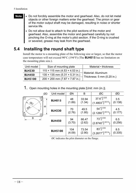
5.4 Installing the round shaft type Install the motor to a mounting plate of the following size or larger, so that the motor case temperature will not exceed 90°C (194°F) (The BLH015 has no limitation on the mounting plate size.).
Unit model Size of mounting plate Material • thickness BLH230 115 × 115 mm (4.53 × 4.53 in.)BLH450 135 × 135 mm (5.31 × 5.31 in.)BLH5100 200 × 200 mm (7.87 × 7.87 in.)
Material: Aluminum Thickness: 5 mm (0.20 in.)
1. Open mounting holes in the mounting plate [Unit: mm (in.)].
Unit model ØA B ØC ØD
BLH015 48 (1.89)
33.94 (1.34)
37.6+0.025 0
(1.4803+0.0010 0 )
3.5 (0.138)
BLH230 70 (2.76)
49.5 (1.95)
54+0.030 0
(2.1260+0.0012 0 )
4.5 (0.177)
BLH450 94 (3.70)
66.47 (2.62)
73+0.030 0
(2.8740+0.0012 0 )
6.5 (0.256)
BLH5100 104 (4.09)
73.54 (2.90)
83+0.035 0
(3.2677+0.0014 0 )
8.5 (0.335)
ØC
B
B
ØA
ØD
ØC indicates the pilot diameter on the flange.
5 Installation
-19-
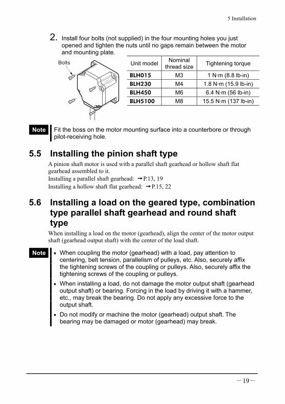
2. Install four bolts (not supplied) in the four mounting holes you just opened and tighten the nuts until no gaps remain between the motor and mounting plate.
Unit model Nominal thread size Tightening torque
BLH015 M3 1 N·m (8.8 lb-in) BLH230 M4 1.8 N·m (15.9 lb-in) BLH450 M6 6.4 N·m (56 lb-in) BLH5100 M8 15.5 N·m (137 lb-in)
Bolts
Note Fit the boss on the motor mounting surface into a counterbore or through pilot-receiving hole.
5.5 Installing the pinion shaft type A pinion shaft motor is used with a parallel shaft gearhead or hollow shaft flat gearhead assembled to it. Installing a parallel shaft gearhead: P.13, 19 Installing a hollow shaft flat gearhead: P.15, 22
5.6 Installing a load on the geared type, combination type parallel shaft gearhead and round shaft type
When installing a load on the motor (gearhead), align the center of the motor output shaft (gearhead output shaft) with the center of the load shaft.
Note • When coupling the motor (gearhead) with a load, pay attention to centering, belt tension, parallelism of pulleys, etc. Also, securely affix the tightening screws of the coupling or pulleys. Also, securely affix the tightening screws of the coupling or pulleys.
• When installing a load, do not damage the motor output shaft (gearhead output shaft) or bearing. Forcing in the load by driving it with a hammer, etc., may break the bearing. Do not apply any excessive force to the output shaft.
• Do not modify or machine the motor (gearhead) output shaft. The bearing may be damaged or motor (gearhead) may break.

5 Installation
-20-
Output shaft shape
Combination type parallel shaft gearhead A key groove is provided on the output shaft of gearhead. Form a key groove on the load side and affix the load using the supplied parallel key.
Unit model Parallel key dimensionBLH230 4 mm (0.1575 in.) BLH450 5 mm (0.1969 in.) BLH5100 6 mm (0.2362 in.)
Geared type, round shaft type A flat section is provided on the motor output shaft of each geared type, round shaft type. Apply a double-point screw, etc., at the flat section to securely affix the load and prevent it from spinning.
How to install a load
• Using a coupling Align the centerline of the motor (gearhead) output shaft with the centerline of the load shaft.
• Using a belt Adjust the motor (gearhead) output shaft to lie parallel with the load shaft and form right angles between the output shaft/load shaft and the line connecting the centers of both pulleys.
• Using a gear Adjust the motor (gearhead) output shaft to lie parallel with the gear shaft and allow the output shaft to mesh correctly with the centers of the gear teeth.
• When using the output axis tip screw hole of a gearhead Use a screw hole [M6, effective depth 12 mm (0.47 in.)] provided at the tip of the output shaft of GFS5G as an auxiliary means for preventing the transfer mechanism from disengaging.
Fixed screw
Screw
Spacer
Transmission parts
The example of output axis tip screw hole use

5 Installation
-21-
Permissible overhung load and permissible thrust load Make sure the overhung load and thrust load received by the motor (gearhead) output shaft will not exceed the allowable values shown in the table below.
Note If the overhung load or thrust load exceeds the specified allowable value, repeated load applications may cause the bearing or output shaft of the motor (gearhead) to undergo a fatigue failure.
Geared type, combination type parallel shaft gearhead Distance from tip of gearhead output shaft and permissible
overhung load [N (lb.)] Unit model∗ 10 mm
(0.39 in.) 20 mm
(0.79 in.)
Permissible thrust load
[N (lb.)]
BLH015K- 50 (11.2) ― 30 (6.7) BLH230KC-5 100 (22) 150 (33) 40 (9) BLH230KC-10, 15, 20 150 (33) 200 (45) 40 (9) BLH230KC-30, 50, 100, 200 200 (45) 300 (67) 40 (9) BLH450KC-5 200 (45) 250 (56) 100 (22) BLH450KC-10, 15, 20 300 (67) 350 (78) 100 (22) BLH450KC-30, 50, 100, 200 450 (101) 550 (123) 100 (22) BLH5100KC-5 300 (67) 400 (90) 150 (33) BLH5100KC-10, 15, 20 400 (90) 500 (112) 150 (33) BLH5100KC-30, 50, 100, 200 500 (112) 650 (146) 150 (33) in the model names indicates a number representing the gear ratio (5, 10, 15, 20, 30, 50,
or 100). ∗ For the lead wire type, “KC” of the unit model is replaced by “K” (except for BLH015
type).
Round shaft type Distance from tip of motor
output shaft and permissible overhung
load [N (lb.)] Unit model∗2
10 mm (0.39 in.)
20 mm (0.79 in.)
Permissible thrust load [N (lb.)]
BLH015K-A 50 (11.2) ― BLH230KC-A 70 (15.7) 100 (22) BLH450KC-A 120 (27) 140 (31) BLH5100KC-A 160 (36) 170 (38)
Not to exceed one-half the motor’s dead weight∗1
∗1 Minimize the thrust load. If a thrust load must be applied, do not let it exceed one-half the motor’s dead weight.
∗2 For the lead wire type, “KC” of the unit model is replaced by “K” (except for BLH015 type).

5 Installation
-22-
5.7 Installing a load on the combination type hollow shaft flat gearhead
If the motor receives a significant impact upon instantaneous stop or is subject to a large overhung load, affix the stepped load shaft.
Note Apply grease (molybdenum disulfide grease, etc.) on the surface of the load shaft and inner walls of the hollow output shaft to prevent seizure.
• Stepped load shaft Install each hexagonal socket head screw over a retaining ring, spacer, washer and spring washer and securely affix the ring.
Stepped load shaft
ØD
Retaining ring
Hollow output shaft
Hexagonal socket head screw
Spring washer
Washer
SpacerParallel key
Load shaft
WasherSpacer
Retaining ring
Spring washer
Hexagonal socket head screw
Parallelkey
• Non-stepped load shaft Install each hexagonal socket head screw over a retaining ring, spacer, washer and spring washer and securely affix the ring. Also, insert a spacer on the load shaft side.
Spacer
Retaining ring
Hollow output shaft
Hexagonal socket head screw
Spring washer
Washer
SpacerParallel key
Load shaft
WasherSpacer
Retaining ring
Spring washer
Hexagonal socket head screw
Spacer
Load shaft
Parallelkey
5 Installation
-23-
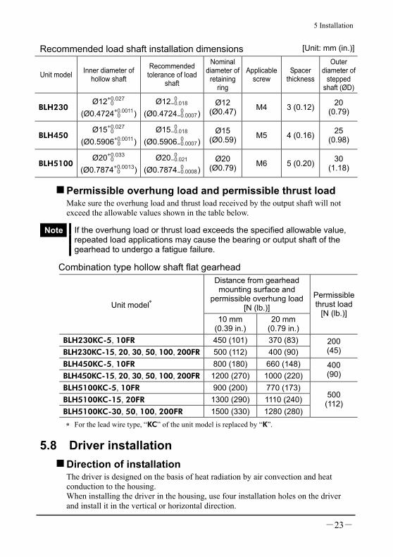
Recommended load shaft installation dimensions [Unit: mm (in.)]
Unit model Inner diameter of hollow shaft
Recommended tolerance of load
shaft
Nominal diameter of
retaining ring
Applicable screw
Spacer thickness
Outer diameter of
stepped shaft (ØD)
BLH230 Ø12+0.027
0
(Ø0.4724+0.0011 0 )
Ø12 0-0.018
(Ø0.4724 0-0.0007)
Ø12 (Ø0.47) M4 3 (0.12) 20
(0.79)
BLH450 Ø15+0.027
0 (Ø0.5906+0.0011
0 )Ø15 0
-0.018 (Ø0.5906 0
-0.0007)Ø15
(Ø0.59) M5 4 (0.16) 25 (0.98)
BLH5100 Ø20+0.033
0 (Ø0.7874+0.0013
0 )Ø20 0
-0.021 (Ø0.7874 0
-0.0008)Ø20
(Ø0.79) M6 5 (0.20) 30 (1.18)
Permissible overhung load and permissible thrust load Make sure the overhung load and thrust load received by the output shaft will not exceed the allowable values shown in the table below.
Note If the overhung load or thrust load exceeds the specified allowable value, repeated load applications may cause the bearing or output shaft of the gearhead to undergo a fatigue failure.
Combination type hollow shaft flat gearhead Distance from gearhead mounting surface and
permissible overhung load [N (lb.)] Unit model∗
10 mm (0.39 in.)
20 mm (0.79 in.)
Permissible thrust load
[N (lb.)]
BLH230KC-5, 10FR 450 (101) 370 (83) BLH230KC-15, 20, 30, 50, 100, 200FR 500 (112) 400 (90)
200 (45)
BLH450KC-5, 10FR 800 (180) 660 (148) BLH450KC-15, 20, 30, 50, 100, 200FR 1200 (270) 1000 (220)
400 (90)
BLH5100KC-5, 10FR 900 (200) 770 (173) BLH5100KC-15, 20FR 1300 (290) 1110 (240)BLH5100KC-30, 50, 100, 200FR 1500 (330) 1280 (280)
500 (112)
∗ For the lead wire type, “KC” of the unit model is replaced by “K”.
5.8 Driver installation Direction of installation The driver is designed on the basis of heat radiation by air convection and heat conduction to the housing. When installing the driver in the housing, use four installation holes on the driver and install it in the vertical or horizontal direction.

5 Installation
-24-
Method of installation Install the driver on a flat metallic plate having an excellent resistance to vibration and heat conduction. Using the driver installation hole or notch, lock the driver with two bolts (M3: not provided) so that there is no gap with the metallic plate. There must be a clearance of at least 25 mm (1 in.) and 50 mm (2 in.) in the horizontal and vertical directions, respectively, between the driver and enclosure or other equipment. When two or more drivers are to be installed in parallel, separate them by 20 mm (0.8 in.) or more in the horizontal direction and by 50 mm (2 in.) or more in the vertical direction as illustrated.
20 mm (0.8 in.)or more
50 m
m (
2 in.)
or
more
20 mm (0.8 in.)or more
50
mm
(2
in
.)
or
mo
re
Note • Do not place any equipment generating much heat or noise around the driver.
• If temperature around the driver is higher than 50°C (122°F), recheck the ventilation conditions and use a fan to provide forced cooling of the driver.
5.9 Installing and wiring in compliance with EMC Directive For EMC Directive (89/336/EEC, 92/31/EEC) The BLH series has been designed and manufactured for incorporation in general industrial machinery. The EMC Directive requires that the equipment incorporating this product comply with these directives. The installation and wiring method for the motor and driver are the basic methods that would effectively allow the customer’s equipment to be compliant with the EMC Directive. The compliance of the final machinery with the EMC Directive will depend on such factors as configuration, wiring, layout and risk involved in the control-system equipment and electrical parts. It therefore must be verified through EMC measures by the customer of the machinery.

5 Installation
-25-
Applicable Standards EMI Emission Tests EN 61000-6-4 Radiated Emission Test EN 55011 EMS Immunity Tests EN 61000-6-2 Electrostatic Discharge Immunity Test IEC 61000-4-2 Radiation Field Immunity Test IEC 61000-4-3 Fast Transient/Burst Immunity Test IEC 61000-4-4 Conductive Noise Immunity Test IEC 61000-4-6 Power Frequency Magnetic Field Immunity Test IEC 61000-4-8
Installing and wiring in compliance with EMC Directive Effective measures must be taken against the EMI that the BLH series may give to adjacent control-system equipment, as well as the EMS of the BLH series itself, in order to prevent a serious functional impediment in the machinery. The use of the following installation and wiring methods will enable the BLH series to be compliant with the EMC Directive (the aforementioned compliance standards).
About power supply The BLH series products are of the DC power supply input specification. Use a DC power supply (such as a switching power supply) that is optimally compliant with the EMC Directive. If a transformer is used in the power supply, be sure to connect a mains filter to the input side of the transformer.
Connecting mains filter for power supply line Install a mains filter in the AC input line to the DC power supply in order to prevent the noise generated within the driver or control system from propagating outside via the DC power supply. For mains filters, use FN2330Y-10-06 or FN2310X-10-06 (Schaffner EMC), 10ESK1 (Tyco Electronics CORCOM), ZAG2210-11S (TDK Corporation), or an equivalent. Install the mains filter as close to the AC input terminal of the DC power supply as possible, and use cable clamps and other means to secure the input and output cables firmly to the surface of the enclosure. Connect the ground terminal of the mains filter to the grounding point, using as thick and short a wire as possible. Do not place the AC input cable parallel with the mains filter output cable. Parallel placement will reduce mains filter effectiveness if the enclosure’s internal noise is directly coupled to the power supply cable by means of stray capacitance.

5 Installation
-26-
Motor cable connection When extending the motor cable, use the optional extension cable. The maximum extension distance including the cable length of the motor itself should be 2 m (6.6 ft.).
Ferrite core Use the ferrite core for extending the motor cable. The ferrite core reduces the negative effects of external noise. Use ferrite core 7427122 (Würth Elektronik GmbH & Co.KG), ZCAT3035-1330 (TDK Corporation) or its equivalent. Connect the ferrite cores as close as possible to the driver.
Wiring the signal cable Use a braided screen cable of AWG26 (0.14 mm2) or more in diameter for the driver signal cable, and keep it as short as possible. To ground a braided screen cable, use a metal clamp or similar device that will maintain contact with the entire circumference of the braided screen cable. Attach a cable clamp as close to the end of the cable as possible, and connect it to an appropriate grounding point as shown in the figure.
Cable clamp
Shielded cable
How to ground The wire used to ground the motor and driver must be as thick and short to the grounding point as possible so that no potential difference is generated. Choose a large, thick and uniformly conductive surface for the grounding point.
How to ground the motor How to ground the driver Connect the grounding wire along with a set screw to the grounding point, using a crow washer.
5 Installation
-27-
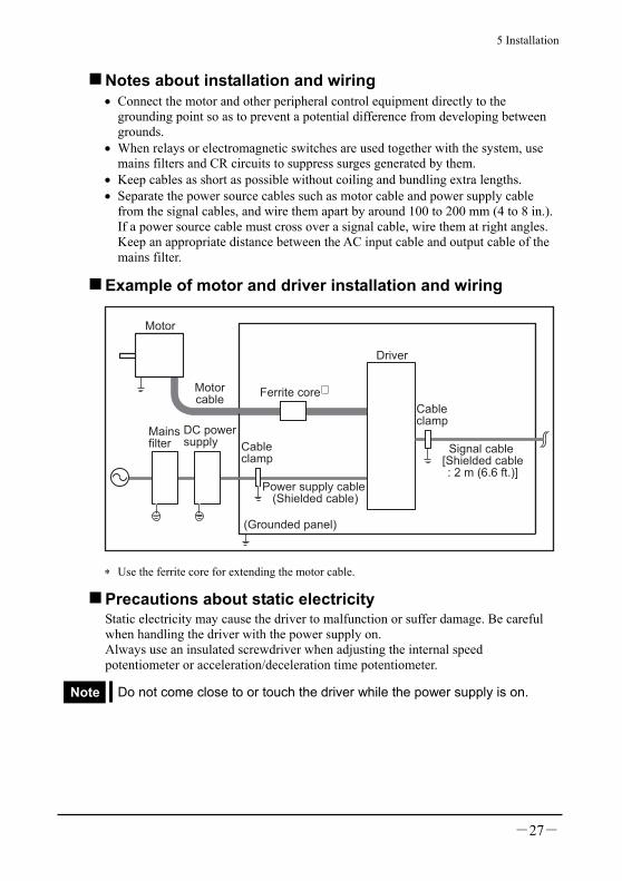
Notes about installation and wiring • Connect the motor and other peripheral control equipment directly to the
grounding point so as to prevent a potential difference from developing between grounds.
• When relays or electromagnetic switches are used together with the system, use mains filters and CR circuits to suppress surges generated by them.
• Keep cables as short as possible without coiling and bundling extra lengths. • Separate the power source cables such as motor cable and power supply cable
from the signal cables, and wire them apart by around 100 to 200 mm (4 to 8 in.). If a power source cable must cross over a signal cable, wire them at right angles. Keep an appropriate distance between the AC input cable and output cable of the mains filter.
Example of motor and driver installation and wiring
Motor
Driver
Cableclamp
Signal cable [Shielded cable: 2 m (6.6 ft.)]
Mainsfilter
DC powersupply Cable
clamp
(Grounded panel)
Power supply cable (Shielded cable)
Motorcable
Ferrite core∗
∗ Use the ferrite core for extending the motor cable.
Precautions about static electricity Static electricity may cause the driver to malfunction or suffer damage. Be careful when handling the driver with the power supply on. Always use an insulated screwdriver when adjusting the internal speed potentiometer or acceleration/deceleration time potentiometer.
Note Do not come close to or touch the driver while the power supply is on.

6 Connection
-28-
6 Connection The following shows the method of connecting the motor and driver, power supply, external potentiometer, earth connection method, an example of connection and I/O signals.
6.1 Motor and driver connection Insert the motor cable connector into the motor connector of the driver.
Unit model Motor connector BLH015, BLH230, BLH450 CN3 BLH5100 CN3, CN4
Note • Firmly insert the connector in position. Incomplete connection of the connector may cause operation failure, or may damage the motor or driver.
• Do not push or pull the cable. Handle only the plastic connector instead. Do not apply force in any direction other than that in which the connector is inserted or pulled out. Improper application of force may damage the connector and driver.
When extending the motor cable, use the optional extension cable. The maximum extension distance including the cable length of the motor itself should be 2 m (6.6 ft.).
6.2 Connecting the power supply Input power supply voltage is 24 VDC ±10%. Insert the power supply cable connector into the driver power supply connector (CN1). If the supplied power supply cable is not used, use a cable of the applicable wire size shown in the table below.
Unit model Power supply cable size BLH015, BLH230, BLH450 AWG22 (0.3 mm2) or more BLH5100 AWG18 (0.75 mm2) or more
Note • Sufficient care must be taken not to mistake the power supply polarity. Connection with incorrect polarity may damage the driver.
• Do not route the driver power supply cable in the same conduit with other power supply lines or motor cables.
• When you want to turn on the power supply again or pull out the motor cable connector, do so 5 s or more after power supply has been turned off.

6 Connection
-29-
6.3 Connection of input signal and output signal
Connection with driver Insert the connector of the I/O signals cable into the connector of the I/O signals cable (CN2) of the driver. The colors in the figure indicate the colors of supplied cables. The specific connections vary depending on the outputs.
BLH015, BLH230, BLH450
START/STOPinput
GND
+24 V
NC
OFF ON
OFF ON
OFF ON
OFF ON
OFF ON
1
12
11
10
9
8
7
6
+
-
5
4
3
2
1
2
1
23
RUN/BRAKEinput
CW/CCWinput
INT.VR/EXT input
ALARM-RESETinput
VRH
VRM
VRL
CN2
CN1
SPEEDoutput
GND
ALARMoutput
To external control device
External
potentiometer∗20 kΩ 1/4 W
Power supply input
External DC power supply∗(For speed setting)
0 to 5 VDC1 mA or more
Black
Red
Black
White
Gray
Brown
Purple
Blue
Green
Yellow
Orange
Red
Brown
24 VDC±10%
∗ Connect either the external potentiometer (option) or DC power supply for the external speed setting.

6 Connection
-30-
BLH5100
START/STOPinput
+24 V
GND
NC
OFF ON
OFF ON
OFF ON
OFF ON
OFF ON
1
12
11
10
9
8
7
6
+
-
5
4
3
2
1
2
1
23
RUN/BRAKEinput
CW/CCWinput
INT.VR/EXT input
ALARM-RESETinput
VRH
VRM
VRL
CN2
CN1
SPEEDoutput
GND
ALARMoutput
To external control device
External
potentiometer∗20 kΩ 1/4 W
Power supply input
External DC power supply∗(For speed setting)
0 to 5 VDC1 mA or more
Red
Black
Black
White
Gray
Brown
Purple
Blue
Green
Yellow
Orange
Red
Brown
24 VDC±10%
∗ Connect either the external potentiometer (option) or DC power supply for the external speed setting.
Note • When extending the I/O signals cable, the length must not exceed 2 m (6.6 ft.). To minimize noise, it should be as short as possible.
• The I/O signals cable must be located 200 mm (8 in.) or more away from such inductive loads as electromagnetic relay, and must cross power supply and motor cables, not parallel to them.
• If you are not using all cables from the terminals provided on the non-connector side of the I/O signals cable, insulate the unused cables to prevent them from contacting other devices, or depending on the applications of these signals connect them to 5 VDC from a user-provided external control device or to a signal ground.

6 Connection
-31-
6.4 Driver I/O circuit and example connection
Input signal The driver’s signal input is a C-MOS input. The signal status indicates “0 to 0.5 V (L level) when ON,” or “4 to 5 V (H level) when OFF.”
• External control device output is a 5 V C-MOS output
• External control device output is an open-collector output
+5 V C-MOS 0.1 µF
2.2 kΩ
GND
+5 V
10 kΩ
START/STOPRUN/BRAKECW/CCWINT.VR/EXTALARM-RESET
C-MOS
Driver internal connections
0 V 0 V
0.1 µF
2.2 kΩ
GND
+5 V
10 kΩ
START/STOPRUN/BRAKECW/CCWINT.VR/EXTALARM-RESET
C-MOSOpen
collector
Driver internal connections
0 V 0 V • Switch connection
0.1 µF
2.2 kΩ
GND
+5 V
10 kΩ
START/STOPRUN/BRAKECW/CCWINT.VR/EXTALARM-RESET
C-MOSSwitch
Driver internal connections
0 V
Output signal The driver’s signal output is a transistor open-collector output. The signal status does not indicate the voltage level of the signal, but it indicates “ON (energized)” or “OFF (not energized)” of the internal transistor.
GND
2SC2458 or equivalent
Driver internal connections
Insert a resistor to keep the current to 10 mA or less
+26.4 V or less10 mA or less
SPEED
ALARM
0 V 0 V

7 Operation
-32-
7 Operation
7.1 Input signals and output signals
Caution Do not perform the motor’s starting and stopping operations by turning the power supply on and off. Perform them by inputting START/STOP and RUN/BRAKE. This may cause injury or damage to the equipment.
Note • The input signals (START/STOP, RUN/BRAKE, CW/CCW, INT.VR/ EXT, ALARM-RESET) must be ON for at least 10 ms. It may cause malfunction of the motor.
• Do not operate (switch the ON/OFF status) of the START/STOP input, RUN/BRAKE input, CW/CCW input and INT.VR/EXT input simultaneously. After switching a given input, wait at least 10 ms before switching another input.
• The motor temperature rise is sharper as friction load and inertial load are higher, and start, instantaneous stop and reversing frequency is higher. It must be used when motor case temperature does not exceed 90°C (194°F), and driver heat radiation plate temperature does not exceed 90°C (194°F).
START/STOP input and RUN/BRAKE input To switch between motor running and instantaneous stop (or stop), use START/STOP input, RUN/BRAKE input.
START/STOP input RUN/BRAKE input Motor operation
ON ON Running ∗1
ON OFF Instantaneous stop Signal level
OFF ON Stop ∗2
∗1 The motor speed can be made to reach the set speed by any one of the internal potentiometer, external potentiometer or external DC voltage. The motor accelerates over the time set by the acceleration/deceleration time potentiometer.
∗2 The motor decelerates over the time set by the acceleration/deceleration time potentiometer.
Note • The BRAKE takes precedence when START/STOP and RUN/BRAKE inputs are turned off simultaneously.
• The actual acceleration/deceleration time is affected by the use condition, load inertia, load torque and other conditions implemented by the user.

7 Operation
-33-
START/STOP input START is selected when the input is ON, and motor starts running. The motor accelerates over the time set by the acceleration/deceleration time potentiometer. STOP is selected when the input is OFF, and motor stops. The motor decelerates over the time set by the acceleration/deceleration time potentiometer.
RUN/BRAKE input RUN is selected when the input is ON, and motor starts running. BRAKE is selected when the input is OFF, and motor stops instantaneously.
Instantaneousstop
Run
OFF
ONSTART/STOP input
RUN/BRAKE input
CW/CCW input
Motor operating pattern
CW
CCWRun
Decelerationstop
START STOP
RUN BRAKE RUN
CCWCW
∗∗ ∗ ∗
∗ 10 ms or more
OFF
ON
OFF
ON
Note Once the motor stops, the output shaft will become free.
CW/CCW input CW is selected when the input is ON. CCW is selected when the input is OFF. The drive direction is the same as that of the motor output shaft when viewed from the motor output side.
Note Depending on the gearhead ratio, the drive direction of the gear output shaft may be opposite of that of the motor. Check the drive direction by referring to 7.2, “Rotating direction of the motor output shaft” on page 39.

7 Operation
-34-
INT.VR/EXT input INT.VR is selected when the input is ON, and the setting speed of internal potentiometer is enabled. EXT is selected when the input is OFF, and the setting speed of external potentiometer or external DC voltage is enabled. Switching this signal allows combined use of the external potentiometer or external DC voltage or two-speed switching operation. When the internal potentiometer is not used, there is no necessity even if there is no connection.
Instantaneousstop
Run
OFF
ONSTART/STOP input
RUN/BRAKE input
CW/CCW input
Motor operating pattern
CW
CCWRun
INT.VR/EXT input
InstantaneousstopRun
INT.VR
EXT
INT.VR
EXT
START
RUN BRAKE RUN
CCWCW
BRAKE
INT.VR INT.VREXT
∗
∗
∗
∗∗
∗ 10 ms or more
OFF
ON
OFF
ON
OFF
ON
EXT

7 Operation
-35-
ALARM-RESET input Use the ALARM-RESET input if you need to move the motor to a specified position or the mechanical home position after the motor has stopped in the middle of operation due to an actuation of the driver’s protective function (ALARM output: OFF). After the motor has been moved, check and remove the cause of the alarm and then reset the alarm. The ALARM can also be reset when the power supply is cycled. For ALARM conditions, see page 36. When the motor is stopped, turn on this signal; then turn it off. This will allow ALARM to be reset. Before inputting the ALARM-RESET, reset either the START/STOP or RUN/BRAKE input to the OFF. If both are ON, ALARM-RESET input will not be accepted.
Run
ALARM output
ALARM-RESET input
Motor operating pattern
CW
CCW Stop
Output
START/STOP inputRUN/BRAKE input OFF
ON
Reset
∗ 10 ms or more
∗ ∗OFF
ON
OFF
ON
∗
StopRun
∗
Note • The START/STOP input and RUN/BRAKE input are not accepted until the ALARM output is reset.
• Turn ON the ALARM-RESET input after confirming that the motor (gearhead) output shaft has stopped completely.

7 Operation
-36-
SPEED output Pulse signals (pulse width: 0.3 ms) of 30 pulses per revolution of the motor output shaft are output in synchronism with the motor drive. Motor speed can be calculated by measuring the SPEED output frequency.
T
0.3 ms
SPEED output frequency = 1
T
Motor speed∗ [r/min] =SPEED output frequency [Hz]
30× 60
∗ The speed of the gear output shaft of a pinion shaft type, geared type or combination type is obtained by dividing the motor speed by the gear ratio.
ALARM output The protection function of the driver activates in following cases, and the ALARM output is turned OFF, thereby stopping the motor. In this case, you can check the contents of the protection function, which was operating by the number of LED flashes. The LED lights for 0.3 s and goes off for 0.3 s. After a specified number of flashes, flashing is performed at intervals of 1.5 s.
LEDflashing cycle
[Example: When it flashes 3 times (Motor sensor error)]
OFF
ON ON ON ON ON ON
0.3 s
0.3 s
1.5 s
Warning When the driver’s protection function is triggered, first remove the cause and then clear the protection function. Continuing the operation without determining the cause of the problem may cause malfunction of the motor, leading to injury or damage to equipment.

7 Operation
-37-
Protection functionNumber of
ALARM LED flashes
Assumed causes
Overload protection function 2 times
• When a load in excess of the rated torque is applied to the motor for about 5 s or more.
• When the motor running/instantaneous stop and drive direction switching is repeated in a short time.
Motor sensor error 3 times
Prevents motor malfunction when the sensor cable within the motor cable is disconnected during motor operation. (An alarm signal will not be output while the motor is at a standstill.)
Overvoltage protection function 4 times
• When the motor is used in an elevating/lowering application or with a load in excess of the permissible load inertia.
• When voltage applied to the driver has exceeded the voltage setting (24 VDC) by 15% or greater.
Insufficient voltage protection function 5 times
When voltage applied to the driver is less than the voltage setting (24 VDC) by 25% or greater.
Overspeed protection function 6 times When motor speed has reached an excess
of 3500 r/min.
If the connection example on page 31 is followed, the ALARM output should remain ON while the driver is normal and turn OFF if an alarm has occurred. If the ALARM output has turned OFF, stop the motor operation and then remove the cause that triggered the applicable protective function by referring to the number of times the LED flashes. After remove the cause for activation of the protection function, reset the ALARM (for ALARM-RESET input, see page 35).
Note The START/STOP input and RUN/BRAKE input are not accepted when the ALARM is OFF.

7 Operation
-38-
Timing chart
Two-step speed selection,deceleration stop
High speed
Lowspeed
Run,Instantaneous stop
Direction of rotation selection
CW(Clockwise direction)
CCW(Counterclockwise direction)
ON
OFF
Motor operating pattern
START/STOP input
CW/CCW input
RUN/BRAKE input
INT.VR/EXT input
START START
CW CCW
RUN RUN RUN
EXT EXTEXT INT.VR INT.VR
CW
∗ 1 ∗ 1
∗ 1∗ 1
∗ 1
∗ 1∗ 1
∗ 1
∗ 1∗ 1
∗ 1
∗ 1
ON
OFF
ON
OFF
ON
OFF
ON
OFFSPEED output
∗ 3
∗ 3
∗ 3
∗ 3
∗ 3
∗ 3
∗ 3
∗ 2
∗ 2
∗1 10 ms or more ∗2 The direction of rotation is the case of the motor alone. It depends on the gear ratio. ∗3 The motor starts and stops over the time set by the acceleration/deceleration time
potentiometer.

7 Operation
-39-
7.2 Rotating direction of the motor output shaft The rotating direction of the motor output shaft is defined as clockwise (CW) or counterclockwise (CCW) as viewed from the motor output shaft. However, the rotating direction of the motor output shaft may vary from that of the gearhead output shaft depending on the gear ratio of the gearhead.
Rotating direction of the gearhead output shaft • Geard type
Ratio 5, 10, 15, 50, 100....................................... Same direction as the motor Ratio 20, 30 ........................................................ Opposite direction to the motor
• Combination type parallel shaft gearhead Ratio 5, 10, 15, 20, 200....................................... Same direction as the motor Ratio 30, 50, 100 ................................................ Opposite direction to the motor
Motor output shaft Gearhead output shaft
CCW directionrotation
CW directionrotation
When the CCW input is ON
When the CW input is ON
• Combination type hollow shaft flat gearhead At all gear ratios, the output shaft turns in the opposite direction to the motor as viewed from the front of the gearhead. With a combination type hollow shaft flat gearhead, the rotating direction will vary depending on whether the motor unit is viewed from the front or rear of the gearhead. Check the direction by referring to the figure below.
Viewed from front Viewed from rear
When the CW input is ON When the CCW
input is ON
When the CW input is ON
When the CCW input is ON

7 Operation
-40-
7.3 Setting the running speed Set the operating speed of the motor using the internal speed potentiometer, external speed potentiometer or external DC voltage. The motor speed range is from 100 to 3000 r/min for the case of the motor alone. Two running speeds can be set by combining the internal potentiometer and external potentiometer, or the internal potentiometer and external DC voltage.
Setting by internal potentiometer This potentiometer is used when running speed setting is not frequently changed, or when two-step speed switching is performed in combination with external speed setting. Adjust the potentiometer using an insulated screwdriver. Clockwise rotation will increase the set speed. The speed is set to 0 r/min at time of shipment. When the motor is driven at the speed set by the internal potentiometer, turn on the INT.VR/EXT input. When you want to use only the internal speed setting potentiometer to set the operation speed, you do not have to connect the VRH, VRM and VRL.
7 Operation
-41-
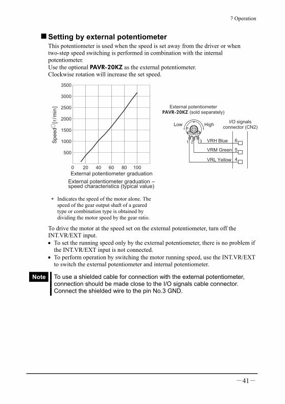
Setting by external potentiometer This potentiometer is used when the speed is set away from the driver or when two-step speed switching is performed in combination with the internal potentiometer. Use the optional PAVR-20KZ as the external potentiometer. Clockwise rotation will increase the set speed.
0 20 40 60 80 100
500
1000
1500
2000
2500
3000
3500
Sp
ee
d∗
[r/m
in]
External potentiometer graduation
External potentiometer graduation - speed characteristics (typical value)
External potentiometerPAVR-20KZ (sold separately)
1 3
HighLow
21 3 6
5
4
VRH Blue
VRM Green
VRL Yellow
I/O signalsconnector (CN2)
∗ Indicates the speed of the motor alone. The speed of the gear output shaft of a geared type or combination type is obtained by dividing the motor speed by the gear ratio.
To drive the motor at the speed set on the external potentiometer, turn off the INT.VR/EXT input. • To set the running speed only by the external potentiometer, there is no problem if
the INT.VR/EXT input is not connected. • To perform operation by switching the motor running speed, use the INT.VR/EXT
to switch the external potentiometer and internal potentiometer.
Note To use a shielded cable for connection with the external potentiometer, connection should be made close to the I/O signals cable connector. Connect the shielded wire to the pin No.3 GND.
7 Operation
-42-
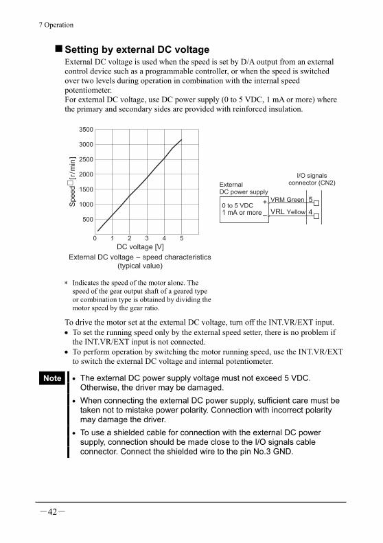
Setting by external DC voltage External DC voltage is used when the speed is set by D/A output from an external control device such as a programmable controller, or when the speed is switched over two levels during operation in combination with the internal speed potentiometer. For external DC voltage, use DC power supply (0 to 5 VDC, 1 mA or more) where the primary and secondary sides are provided with reinforced insulation.
0 1 2 3 4 5
500
1000
1500
2000
2500
3000
3500
Sp
ee
d∗
[r/m
in]
DC voltage [V]
External DC voltage - speed characteristics(typical value)
External DC power supply
0 to 5 VDC1 mA or more
+
-
5
4
VRM Green
VRL Yellow
I/O signalsconnector (CN2)
∗ Indicates the speed of the motor alone. The speed of the gear output shaft of a geared type or combination type is obtained by dividing the motor speed by the gear ratio.
To drive the motor set at the external DC voltage, turn off the INT.VR/EXT input. • To set the running speed only by the external speed setter, there is no problem if
the INT.VR/EXT input is not connected. • To perform operation by switching the motor running speed, use the INT.VR/EXT
to switch the external DC voltage and internal potentiometer.
Note • The external DC power supply voltage must not exceed 5 VDC. Otherwise, the driver may be damaged.
• When connecting the external DC power supply, sufficient care must be taken not to mistake power polarity. Connection with incorrect polarity may damage the driver.
• To use a shielded cable for connection with the external DC power supply, connection should be made close to the I/O signals cable connector. Connect the shielded wire to the pin No.3 GND.
7 Operation
-43-
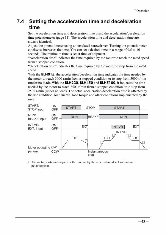
7.4 Setting the acceleration time and deceleration time
Set the acceleration time and deceleration time using the acceleration/deceleration time potentiometer (page 11). The acceleration time and deceleration time are always identical. Adjust the potentiometer using an insulated screwdriver. Turning the potentiometer clockwise increases the time. You can set a desired time in a range of 0.5 to 10 seconds. The minimum time is set at time of shipment. “Acceleration time” indicates the time required by the motor to reach the rated speed from a stopped condition. “Deceleration time” indicates the time required by the motor to stop from the rated speed. With the BLH015, the acceleration/deceleration time indicates the time needed by the motor to reach 3000 r/min from a stopped condition or to stop from 3000 r/min (under no load). With the BLH230, BLH450 and BLH5100, it indicates the time needed by the motor to reach 2500 r/min from a stopped condition or to stop from 2500 r/min (under no load). The actual acceleration/deceleration time is affected by the use condition, load inertia, load torque and other conditions implemented by the user.
Instantaneousstop
EXT
OFFONSTART/
STOP input
RUN/BRAKE input
INT.VR/EXT. input
Motor operating pattern
CW
CCW
START
RUN BRAKE RUN
EXT
OFFON
OFFON
STARTSTOP
∗
EXTINT.VR
INT.VR
EXT EXT∗ ∗
∗ ∗∗
∗ The motor starts and stops over the time set by the acceleration/deceleration time potentiometer.
7 Operation
-44-
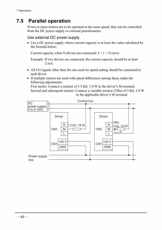
7.5 Parallel operation If two or more motors are to be operated at the same speed, they can be controlled from the DC power supply or external potentiometer.
Use external DC power supply • Use a DC power supply whose current capacity is at least the value calculated by
the formula below:
Current capacity when N drivers are connected: I = 1 × N (mA)
Example: If two drivers are connected, the current capacity should be at least 2 mA.
• All I/O signals other than the one used for speed setting should be connected to each driver.
• If multiple motors are used with speed differences among them, make the following adjustments: First motor: Connect a resistor of 1.5 kΩ, 1/4 W to the driver’s M terminal. Second and subsequent motors: Connect a variable resistor (VRn) of 5 kΩ, 1/4 W to the applicable driver’s M terminal.
H
MCN2
CN1
L
+24 V
GND
Driver
H
M
L
Driver
Control line
1.5 kΩ, 1/4 W
DC power supply0 to 5 VDC
Power supplyline
+
-
VRn5 kΩ, 1/4 W
CN2
CN1+24 V
GND

7 Operation
-45-
Use an external potentiometer Use common lines for the power supply and speed control and set the speed using VRx, as shown below. • Obtain the resistance for the external speed potentiometer as follows:
Resistance when N drivers are connected: VRx = 20/N (kΩ), N/4 (W)
Example: If two drivers are connected, the current capacity should be 10 kΩ, 1/2 W.
• All I/O signals other than the one used for speed setting should be connected to each driver.
• If multiple motors are used with speed differences among them, make the following adjustments: First motor: Connect a resistor of 1.5 kΩ, 1/4 W to the driver’s M terminal. Second and subsequent motors: Connect a variable resistor (VRn) of 5 kΩ, 1/4 W to the applicable driver’s M terminal.
• Keep the number of drivers to five or less in parallel operation using an external potentiometer.
3
2VRx
1
Control line
1.5 kΩ, 1/4 W
VRn5 kΩ, 1/4 WH
M
L
Driver
H
M
L
Driver
Power supplyline
CN2
CN1+24 V
GND
CN2
CN1+24 V
GND

8 Inspection
-46-
8 Inspection It is recommended to check the following four items after motor operation. If any failure is found, stop the operation, and please contact your local sales office.
Inspection items • Check if abnormal noise is produced from the motor bearing section (ball
bearing). • Check if abnormal noise is produced from the gearhead bearing (ball bearing) and
gear meshing section. • Check if the motor cable is damaged or stressed. Also, check if the connections
with the driver are loosened. • Check if there is any misalignment between motor (gearhead) output and load
shafts. • Check if dust is deposited on the driver.
Note Conduct the insulation resistance measurement or withstand voltage test separately on the motor and the driver.
9 Troubleshooting and remedial actions
-47-
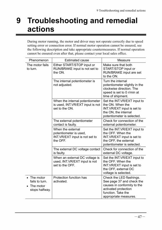
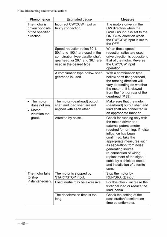
9 Troubleshooting and remedial actions During motor running, the motor and driver may not operate correctly due to speed setting error or connection error. If normal motor operation cannot be ensured, see the following description and take appropriate countermeasures. If normal operation cannot be ensured even after that, please contact your local sales office.
Phenomenon Estimated cause Measure Either START/STOP input or RUN/BRAKE input is not set to the ON.
Make sure that both START/STOP input or RUN/BRAKE input are set to the ON.
The internal potentiometer is not adjusted.
Turn the internal potentiometer slightly in the clockwise direction. The speed is set to 0 r/min at time of shipment.
When the internal potentiometer is used, INT.VR/EXT input is not set to the ON.
Set the INT.VR/EXT input to the ON. When the INT.VR/EXT input is set to the ON, the internal potentiometer is selected.
The external potentiometer contact is faulty.
Check for connection of the external potentiometer.
When the external potentiometer is used, INT.VR/EXT input is not set to the OFF.
Set the INT.VR/EXT input to the OFF. When the INT.VR/EXT input is set to the OFF, the external potentiometer is selected.
The external DC voltage contact is faulty.
Check for connection of the external DC voltage.
The motor fails to turn.
When an external DC voltage is used, INT.VR/EXT input is not set to the OFF.
Set the INT.VR/EXT input to the OFF. When the INT.VR/EXT input is set to the OFF, external DC voltage is selected.
• The motor fails to turn.
• The motor stops halfway.
Protection function has activated.
Check the LED flashings. See page 37 and check the causes in conformity to the activated protection function. Take the appropriate measures.
9 Troubleshooting and remedial actions
-48-
Phenomenon Estimated cause Measure Incorrect CW/CCW input or faulty connection.
The motors driven in the CW direction when the CW/CCW input is set to the ON. CCW direction when the CW/CCW input is set to the OFF.
Speed reduction ratios 30:1, 50:1 and 100:1 are used in the combination type parallel shaft gearhead, or 20:1 and 30:1 are used in the geared type.
When these speed reduction ratios are used, drive direction is opposite to that of the motor. Reverse the CW/CCW input operation.
The motor is driven opposite of the specified direction.
A combination type hollow shaft gearhead is used.
With a combination type hollow shaft flat gearhead, the rotating direction will vary depending on whether the motor unit is viewed from the front or rear of the gearhead (P.39).
The motor (gearhead) output shaft and load shaft are not aligned with each other.
Make sure that the motor (gearhead) output shaft and load shaft are connected in an appropriate manner.
• The motor does not run.
• Motor vibration too great. Affected by noise. Check for running only with
the motor, driver and external potentiometer required for running. If noise influence has been confirmed, take the appropriate measures such as separation from noise generating source, re-connection of wiring, replacement of the signal cable by a shielded cable, and installation of a ferrite core.
The motor is stopped by START/STOP input.
Stop the motor by RUN/BRAKE input.
Load inertia may be excessive. For this check, increase the frictional load or reduce the load inertia.
The motor fails to stop instantaneously.
The deceleration time is too long.
Check the setting of the acceleration/deceleration time potentiometer.

9 Troubleshooting and remedial actions
-49-

10 Appendix
-50-
10 Appendix
10.1 Options (sold separately) The optional parts and accessories for the BLH series are explained.
Extension cable Use this cable to extend the wiring distance between the motor and driver.
Model Length Applicable product CC02BLH BLH015, BLH230, BLH450CC02AXH2
1.5 m (4.9 ft.) BLH5100
External potentiometer Model: PAVR-20KZ This external potentiometer consists of a variable resistor, insulation sheet, dial plate and dial.
• How to install the external potentiometer
1. Insert the external potentiometer over the insulation sheet into the hole provided in the mounting plate, as illustrated below.
2. Set the dial plate and toothed washer, and tighten with the nut. Tightening torque: 0.45 N·m (3.9 lb-in)
3. Install the dial and secure it with the setscrew (M4). Tightening torque: 0.4 N·m (3.5 lb-in)
· Reference mounting hole dimensions [Unit: mm (in.)]
Ø3 (Ø0.12)
7.5 ±0.4 (0.30 ±0.016)
Ø10 (Ø0.39)
Dial
NutToothed washer
Dial plate
Mounting plateInsulation sheetPotentiometer
Setscrew
10 Appendix
-51-
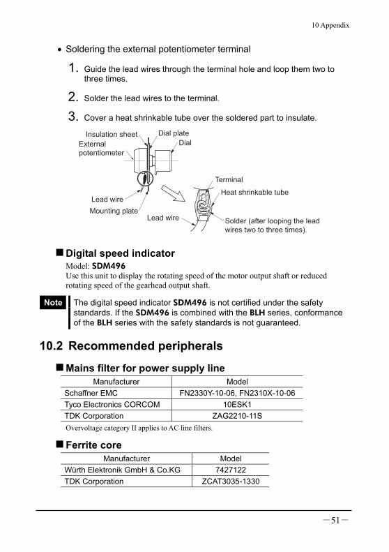
• Soldering the external potentiometer terminal
1. Guide the lead wires through the terminal hole and loop them two to three times.
2. Solder the lead wires to the terminal.
3. Cover a heat shrinkable tube over the soldered part to insulate.
DialExternalpotentiometer
Dial plate
Mounting plate
Lead wire
Insulation sheet
Lead wire
Terminal
Heat shrinkable tube
Solder (after looping the lead wires two to three times).
Digital speed indicator Model: SDM496 Use this unit to display the rotating speed of the motor output shaft or reduced rotating speed of the gearhead output shaft.
Note The digital speed indicator SDM496 is not certified under the safety standards. If the SDM496 is combined with the BLH series, conformance of the BLH series with the safety standards is not guaranteed.
10.2 Recommended peripherals
Mains filter for power supply line Manufacturer Model
Schaffner EMC FN2330Y-10-06, FN2310X-10-06Tyco Electronics CORCOM 10ESK1 TDK Corporation ZAG2210-11S Overvoltage category II applies to AC line filters.
Ferrite core Manufacturer Model
Würth Elektronik GmbH & Co.KG 7427122 TDK Corporation ZCAT3035-1330

• Unauthorized reproduction or copying of all or part of this manual is prohibited. If a new copy is required to replace an original manual that has been damaged or lost, please contact your nearest Oriental Motor branch or sales office.
• Oriental Motor shall not be liable whatsoever for any problems relating to industrial property rights arising from use of any information, circuit, equipment or device provided or referenced in this manual.
• Characteristics, specifications and dimensions are subject to change without notice. • While we make every effort to offer accurate information in the manual, we welcome
your input. Should you find unclear descriptions, errors or omissions, please contact the nearest office.
• is a registered trademark or trademark of Oriental Motor Co., Ltd., in Japan and other countries. Other product names and company names mentioned in this manual may be registered trademarks or trademarks of their respective companies and are hereby acknowledged. The third-party products mentioned in this manual are recommended products, and references to their names shall not be construed as any form of performance guarantee. Oriental Motor is not liable whatsoever for the performance of these third-party products.
© Copyright ORIENTAL MOTOR CO., LTD. 2007
Printed on Recycled Paper
• Please contact your nearest Oriental Motor office for further information.
Technical Support Tel:(800)468-39828:30 A.M. to 5:00 P.M., P.S.T. (M-F)7:30 A.M. to 5:00 P.M., C.S.T. (M-F)E-mail: [email protected]
Headquarters and Düsseldorf OfficeTel:0211-52067-00 Fax:0211-52067-099Munich Office Tel:089-3181225-00 Fax:089-3181225-25Hamburg OfficeTel:040-76910443 Fax:040-76910445
Tel:01256-347090 Fax:01256-347099
Tel:01 47 86 97 50 Fax:01 47 82 45 16
Tel:02-93906346 Fax:02-93906348
Tel:(02)8228-0707 Fax:(02)8228-0708
Tel:(6745)7344 Fax:(6745)9405
Tel:(03)22875778 Fax:(03)22875528
KOREATel:(032)822-2042~3 Fax:(032)819-8745
Headquarters Tokyo, JapanTel:(03)3835-0684 Fax:(03)3835-1890
Tel:66-2-254-6113 Fax:66-2-254-6114