Bruno VPL-3300B Series€¦ · • NFPA 70 - National Electric Code Vertical Platform Lift...
46
www.bruno.com Bruno VPL-3300B Series Enclosure Application - Design and Planning Guide
Transcript of Bruno VPL-3300B Series€¦ · • NFPA 70 - National Electric Code Vertical Platform Lift...

w w w. b r u n o . c o m
Bruno VPL-3300B SeriesEnclosure Application - Design and Planning Guide
Bruno VPL-3300B Series Enclosure Design and Planning Guide
bruno.com/cvpl | 1-800-848-30562
Table of contents
Planning Guide Purpose ........................................................................3
Vertical Platform Lift Definition ............................................................3
Benefits of Vertical Platform Lifts .........................................................3
Design Assistance ................................................................................3
General Information ............................................................................3
How it Works/Key Components ..........................................................4-5
Difference Between Enclosure and Hoistway/Shaftway ...........................5
Lift Height and Floor-to-Floor Measuring ...............................................6
Platforms ............................................................................................6
Platform Configurations .......................................................................7
Operating Controls ..............................................................................8
Options ......................................................................................... 9-10
Enclosure Doors and Gates ................................................................. 11
Site Construction Details .................................................................... 12
Application Specific Drawings ....................................................... 13-36
Landing Gate Detail ...................................................................... 37-40
Bruno VPL-3300B Series

Bruno VPL-3300B Series Enclosure Design and Planning Guide
1-800-848-3056 | bruno.com/cvpl 3
Planning Guide Purpose
Use this planning guide to gain details on incorporating a Bruno Enclosure Vertical Platform Lift into a public building design. All Bruno commercial vertical platform lifts meet the following applicable codes and performance standards: • ASME A18.1-2011 Section 2 (Public) Safety Standards for Platform Lifts and Stairway Chairlifts • ASME A18.1-2014 Section 2 (Public) Safety Standards for Platform Lifts and Stairway Chairlifts • CAN/CSA B355-09 (Public) Lifts for Persons with Physical Disabilities • CAN/CSA B355-15 (Public) Lifts for Persons with Physical Disabilities • CSA B44.1-11/ASME A17.5-2011 - Elevator and Escalator Electrical Equipment • CSA B44.1-14/ASME A17.5-2014 - Elevator and Escalator Electrical Equipment • CSA - National Electric Code • NFPA 70 - National Electric Code
Vertical Platform Lift Definition
Vertical platform lifts (VPLs) are a cost-effective solution to make a church, school, office or other public building accessible for people using mobility devices. Sometimes called a wheelchair lift, a VPL provides code-compliant access up to 14’ in a variety of configurations (check with local jurisdiction) and are suitable for indoor or outdoor use.
Benefits of Vertical Platform Lifts
When providing access up to 14’ for a person in a wheelchair or other mobility device, code-compliant options include traditional elevators, ramps and vertical platform lifts. Vertical platform lifts can provide significant cost and space efficiencies.
Cost-EffectiveGain cost efficiencies by installing a vertical platform lift instead of an elevator or long ramp system.
CompactRamps require 12” horizontal travel for every 1” vertical travel. For example, a 36” rise would require a 36’ ramp. In addition to taking up significant space, ramps can be fatiguing. A vertical platform lift saves space and is automatically powered.
Meets USA ADA RequirementsVertical platform lifts are acknowledged in the Americans with Disabilities Act (ADA) Accessibility Guidelines as a means to provide public building access. Bruno VPLs are designed in accordance with ASME A18.1 section 2.
Design Assistance
Need help on specifying the right VPL configuration? Bruno’s commercial VPL support professionals can help design the right solution for your project. Email: [email protected]. Phone: 800.848.3056
General Information
FinishesBruno’s commercial VPL standard finish is electrostatically applied with a baked powder coat finish in champagne color. Platform and landing gate parts are E-coated for an extra level of protection from the outdoor elements.
Indoor / Outdoor All Bruno VPLs are suitable for indoor and outdoor applications. Optional cold-weather package recommended if operating temperature is below 20° F/-7°C.
Enclosure Vertical Platform Lift, access up to 14’

Bruno VPL-3300B Series Enclosure Design and Planning Guide
bruno.com/cvpl | 1-800-848-30564
How It Works – Enclosure
Bruno’s Enclosure Vertical Platform lift is lightweight, easy to install and available in multiple configurations for access up to 14’. Enclosure VPLs are self-contained, so no additional construction of a hoistway or shaftway is needed. All Bruno Enclosure configurations include an ACME screw-driven system
with full-time battery operation, platform with side walls, and interlock door system. With full-size Plexiglas door and panel inserts, Bruno’s Enclosure VPL wheelchair lift is an attractive choice for ADA compliance. Bruno VPLs are Made-in-America.
Upper landing gate
Platform side wall
Grab rail (other side of platform wall)
Non-skid platform
Plexiglas panels
Fascia wall
Non-skid stationary ramp
Factory enclosure aluminum door with Plexiglas panels
Tower/Mast
Lighted platform controls w/AV alarm & emergency stop
Platform side wall
Enclosure key components

Bruno VPL-3300B Series Enclosure Design and Planning Guide
1-800-848-3056 | bruno.com/cvpl 5
ACME Screw Drive System (image shown is a “tall” model)
Power requirements: 120VAC, 3A, single phase, 60 Hz
Manual lowering tool: An optional manual hand crank is offered to lower the device. The manual lowering hand-wheel has a black plastic handle and slotted shape that engages a square key on the main screw drive.
Emergency Battery Lowering System: standard on VPL models VPL-3310B, VPL-3312B, & VPL-3314B. In the event of a power failure, models VPL-3310B, VPL-3312B, and VPL-3314B have an external lockable keyed switch for lowering the platform by means of a separate battery located inside the electrical enclosure (control box).
Emergency Lowering Battery Backup Access Box Standard on tall VPLs only (Models VPL-3310B, VPL-3312B, and VPL-3314B)
Difference between Enclosure and Shaftway/Hoistway
EnclosureAll equipment is self-contained in an Enclosure VPL. All running clearances are built in, and it is constructed with an aluminum frame and Plexiglas side walls with a full-size Plexiglas door.
Shaftway/HoistwayThe vertical platform lift is placed inside a shaftway/hoistway built by others. The lift is hidden from sight behind two doors and equipment is placed inside the shaftway which is built to site drawings and meets running clearances of the lift.
Enclosure model Shaftway model
Tower/Mast cover
Belt drive
ACME Screw
Control box
Motor
Upper/lower limit switches
Travel carriage
Batteries

Bruno VPL-3300B Series Enclosure Design and Planning Guide
bruno.com/cvpl | 1-800-848-30566
Lift Heights and Floor-to-Floor Measuring
PitLower Landing
LiftHeight
3” Pit Depth
Upper Landing
Pit installation = Pit to floor distance
Floor installation = Floor to floor distance
Lower Landing
Upper Landing
LiftHeight
PitLower Landing
LiftHeight
3” Pit Depth
Upper Landing
Pit installation = Pit to floor distance
Floor installation = Floor to floor distance
Lower Landing
Upper Landing
LiftHeight
Enclosure MeasuresModel Max Floor-to-Floor Min Floor-to-Floor Mast Height Unit Height Unit Weight
VPL-3353B 53” 11” 75-9/16” 95” 897 lb
VPL-3375B 75” 53” 97-9/16” 117” 970 lb
VPL-3310B 123” 75” 148-1/16” 165” 1210 lb
VPL-3312B 147” 75” 172-1/16” 189” 1304 lb
VPL-3314B 171” 75” 196-1/16” 213” 1400 lb
Platforms
The rated load for the platform is 750 lbs. Solid side platform walls measure 42” high. See below for typical platform features and components.
Platform Size Options: • 36” x 54” – standard • 36” x 48” • 36” x 60” • 42” x 60”
Lift height is defined as the distance from the lower landing where the lift will be placed to the upper landing. The lift can be installed with or without a pit. In a pit Installation, the measurement is from the bottom of the pit to the upper landing. For a floor installation, the measurement is from the floor to the upper landing.
Model selection is determined by floor-to-floor lift height, a critical measurement in designing a vertical platform lift. See below for a table to select the appropriate model based on lift height.
42” high sidewalls
Bottom platform safety panel
Non-skid platform surface
Grab rail
ADA compliant telephone (optional)
Lighted and keyed control panel w/rocker switch and emergency stop with audio visual alarm
Bruno VPL-3300B Series Enclosure Design and Planning Guide
1-800-848-3056 | bruno.com/cvpl 7
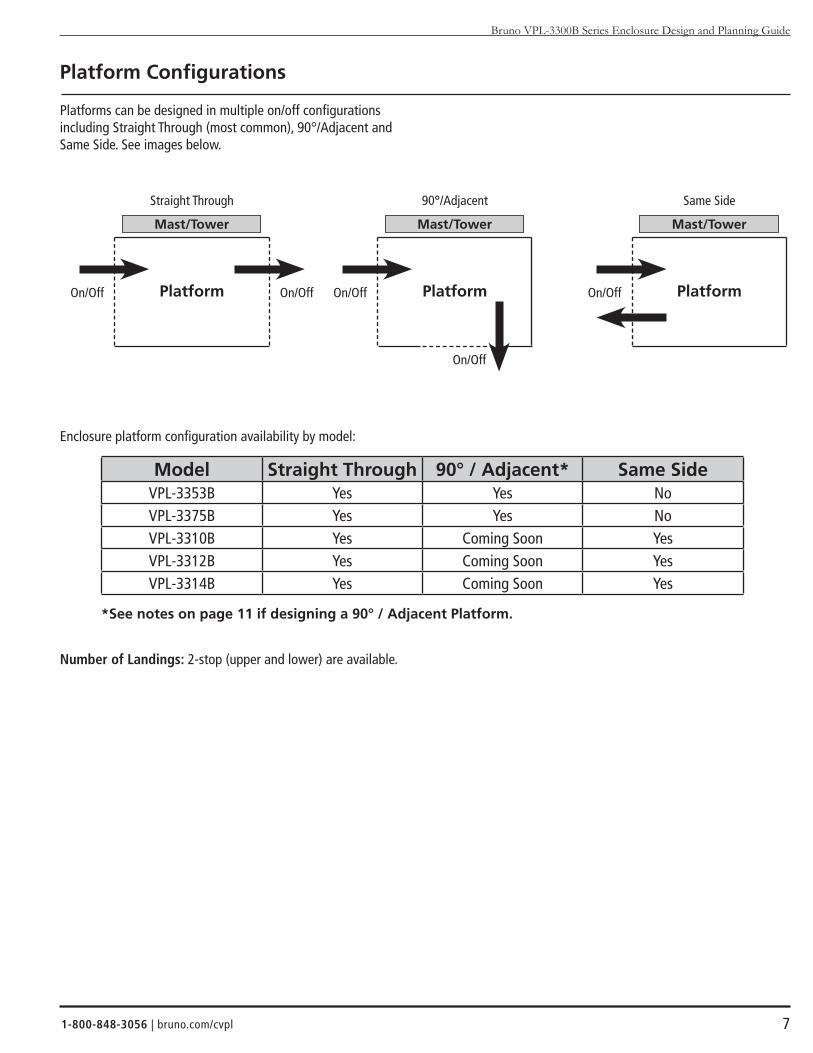
Platform Configurations
Platforms can be designed in multiple on/off configurations including Straight Through (most common), 90°/Adjacent and Same Side. See images below.
Enclosure platform configuration availability by model:
Number of Landings: 2-stop (upper and lower) are available.
Model Straight Through 90° / Adjacent* Same SideVPL-3353B Yes Yes NoVPL-3375B Yes Yes NoVPL-3310B Yes Coming Soon YesVPL-3312B Yes Coming Soon YesVPL-3314B Yes Coming Soon Yes
*See notes on page 11 if designing a 90° / Adjacent Platform.
PlatformOn/Off On/Off
Straight Through
Mast/Tower
PlatformOn/Off
On/Off
90°/Adjacent
Mast/Tower
PlatformOn/Off
Same Side
Mast/Tower

Bruno VPL-3300B Series Enclosure Design and Planning Guide
bruno.com/cvpl | 1-800-848-30568
Operating Controls
Platform Controls: All Bruno VPL-3300B Series lifts come standard with weather-protected, continuous pressure up and down rocker switch platform control. Optional paddle style control is available.
Call/Sends: Optional remote call/send controls come in rocker or paddle style and either flush or surface mount installation. Used on upper and lower landings.
Upper Landing Controls: Optional upper landing gate controls are also available in both rocker or paddle style control.
Rocker Switch Platform Control Paddle Platform Control
Rocker / Surface mount Paddle / Flush Mount
Rocker Paddle

Bruno VPL-3300B Series Enclosure Design and Planning Guide
1-800-848-3056 | bruno.com/cvpl 9
Additional Options
ADA Phone with Battery Backup Platform Gate Operator Doors and Upper Landing Gate Operator
Cold weather package: recommended if operating temperature is below 20°F (-7°C)
Cable carrier/guide
Hardware
Mounting bracket
Cold weather ACME screw grease
Junction box assembly
Battery warmers

Bruno VPL-3300B Series Enclosure Design and Planning Guide
bruno.com/cvpl | 1-800-848-305610
Additional Options cont.
Battery Package Upgrade – 34AH (upgrade package for VPL-3353B & VPL-3375B only)
Pit SwitchMounts inside the enclosure and ensures safety of someone working beneath the platform.
Flood Sensor The flood sensor is used to detect water near the bottom of the VPL. The sensor can be mounted anywhere below the lower limit switches. When water is detected, the platform will stop moving in either up or down direction.
34AH Batteries

Bruno VPL-3300B Series Enclosure Design and Planning Guide
1-800-848-3056 | bruno.com/cvpl 11
Bruno Enclosure Doors and Gates
The Enclosure model includes a full-size aluminum framed door with Plexiglas panels for the lower landing. This door is equipped with an electric strike interlock system (ESI), is non-fire rated and comes pre-hung in an aluminum frame (optional for use at the upper landing). The height of the door is 80” and is available in two widths: - 36” door (33-3/8” inside opening), 42” frame - 45” door (42-3/8” inside opening), 51” frame
Another option is Bruno’s upper landing gate includes Bruno’s electrical mechanical interlock (EMI) or optional electric strike interlock (ESI), which releases the gate when platform is at the upper landing. Electronic sensors stop the platform from operating unless the gate is closed. Rocker switch upper landing control comes mounted to the gate. Paddle switch and/or remote mount are optional. Available with steel or Plexiglas panels in two sizes: - 36” W x 42” H - 42” W x 42” H
Hand of Mast / Tower
Hand of mast / tower is determined by the side the mast / tower is on when entering the lift at the lower landing. See below.
Gate and Door Swing Direction
Identify gate or door swing based on the direction the gate or door opens from the platform (see drawing below). For example, if a user’s back is to the hinge and the right arm would be used to open the door or gate, it would require a right-hand swing.
Please note the following for most 90° / Adjacent Platforms: - Left hand mast / tower requires right hand upper landing gate with EMI interlock. - Right hand mast / tower requires left hand upper landing gate with EMI interlock. - If this configuration cannot be achieved due to any design or structure requirements, an upper landing gate with an ESI lock can be used and this requirement will not apply.
Low
er la
ndin
g
Mast / Tower
Platform
Left hand Mast / Tower
Low
er la
ndin
g
Mast / Tower
Platform
Right hand Mast / Tower
Mast / Tower
PlatformRH
LHLHRH
LHRH
Steel panel, rocker switch Plexiglas panel, paddle control

Bruno VPL-3300B Series Enclosure Design and Planning Guide
bruno.com/cvpl | 1-800-848-305612
Site Construction Details
Electrical Requirements:Check applicable local codes for all electrical and wiring requirements. If it is determined that a GFI (Ground Fault Interrupter) outlet is required, use a GFI 120V, 15A, 60 Hz single phase circuit to operate the internal battery charger (charger draws 3A max.). National Electrical Code requires a GFI is used in all outdoor or wet environment applications.
Platform Pathway Requirements:Make sure the platform pathway is clear of any electrical conduit and wire ways. Make sure no liquids, steam or gas piping discharge into the pathway, and ensure that there is sufficient headroom clearance (minimum of 80”– 2032 mm) throughout floor-to-floor travel. The area should be sufficiently lit.
Floor Recommendations:A 4” (102 mm) thick, 3500 PSI minimum compressive strength, reinforced concrete slab. Refer to technical drawings for mini-mum slab dimensions. If the temperature can fall below freezing, it is recommended that you insert an insulation sheet between the concrete slab and the compacted rock.
Floor Attachment:VPL must be fastened to concrete slab using four (4) 1/2” (3/8” bolt) x minimum 2-1/2” long concrete anchors suitable for the environment. Refer to technical drawings for mounting hole locations. Follow selected concrete anchor manufacturer’s guidelines and applicable codes.
Top Landing Gate Attachment:Gate is mounted to the enclosure on the sides then secured to the top landing along the sill.
Space Requirements:Refer to application specific drawings starting on page 13.
Platform-to-Top Landing Sill Clearance:ASME code indicates the platform floor-to-sill clearance at the upper landing shall not be less than 3/8” (9.5 mm) nor exceed 3/4” (19 mm). Follow applicable local codes.
Fascia Wall Requirements:ASME code indicates that fascia should be smooth and/or non-perforated that guards the full length and width of the platform. The fascia wall is supplied with the enclosure.

13
Ap
plic
atio
n S
pec
ific
Dra
win
gs
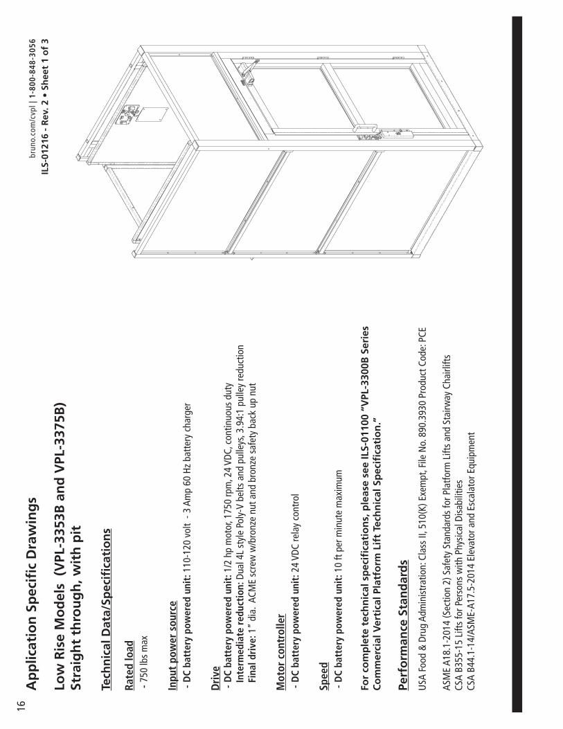
Low
Ris
e M
od
els
(V
PL-3
353B
an
d V
PL-3
375B
) St
raig
ht
thro
ug
h, n
o p
it
Tech
nic
al D
ata/
Spec
ifica
tio
ns
Rate
d lo
ad -
750
lbs
max
Inpu
t po
wer
sou
rce
- D
C ba
tter
y po
wer
ed u
nit:
110
-120
vol
t - 3
Am
p 60
Hz
batt
ery
char
ger
Dri
ve -
DC
batt
ery
pow
ered
uni
t: 1
/2 h
p m
otor
, 175
0 rp
m, 2
4 VD
C, c
ontin
uous
dut
y
Inte
rmed
iate
red
ucti
on: D
ual 4
L st
yle
Poly
-V b
elts
and
pul
leys
, 3.9
4:1
pulle
y re
duct
ion
Fi
nal d
rive
: 1”
dia.
ACM
E sc
rew
w/b
ronz
e nu
t and
bro
nze
safe
ty b
ack
up n
ut
Mot
or c
ontr
olle
r -
DC
batt
ery
pow
ered
uni
t: 2
4 VD
C re
lay
cont
rol
Spee
d -
DC
batt
ery
pow
ered
uni
t: 1
0 ft
per m
inut
e m
axim
um
For
com
ple
te t
ech
nic
al s
pec
ifica
tio
ns,
ple
ase
see
ILS-
0110
0 “V
PL-3
300B
Ser
ies
Co
mm
erci
al V
erti
cal P
latf
orm
Lif
t Te
chn
ical
Sp
ecifi
cati
on
.”
Perf
orm
ance
Sta
nd
ard
s
USA
Foo
d &
Dru
g Ad
min
istr
atio
n: C
lass
II, 5
10(K
) Exe
mpt
, File
No.
890
.393
0 Pr
oduc
t Cod
e: P
CE
ASM
E A1
8.1-
2014
(Sec
tion
2) S
afet
y St
anda
rds
for P
latfo
rm L
ifts
and
Stai
rway
Cha
irlift
sCS
A B3
55-1
5 Li
fts fo
r Per
sons
with
Phy
sica
l Dis
abili
ties
CSA
B44.
1-14
/ASM
E-A1
7.5-
2014
Ele
vato
r and
Esc
alat
or E
quip
men
t
ILS-
0121
5 -
Rev
. 1 •
Sh
eet
1 o
f 3
brun
o.co
m/c
vpl |
1-8
00-8
48-3
056
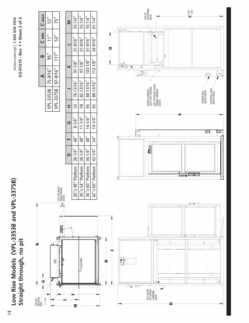
14
G
M
JH
7 1/
4"
K
F
L
B
A
C
D
AB
C M
INC
MA
X
VPL-
3353
B75
-9/1
6”95
”11
”53
”VP
L-33
75B
97-9
/16”
117”
53”
75”
Low
Ris
e M
od
els
(V
PL-3
353B
an
d V
PL-3
375B
) St
raig
ht
thro
ug
h, n
o p
it
DF
GH
JK
LM
36”x
48”
Pla
tform
36-1
/4”
48”
8-1/
4”53
76-1
3/16
”91
-1/8
”31
-9/1
6”55
-1/4
”36
”x 5
4” P
latfo
rm36
-1/4
”48
”11
-1/4
”59
82-1
3/16
”97
-1/8
”31
-9/1
6”55
-1/4
”36
”x 6
0” P
latfo
rm36
-1/4
”48
”14
-1/4
”65
88-1
3/16
”10
3-1/
8”31
-9/1
6”55
-1/4
”42
”x 6
0” P
latfo
rm42
-1/4
”54
”14
-1/4
”65
88-1
3/16
”11
2-1/
8”34
-9/1
6”61
-1/4
”
ILS-
0121
5 -
Rev
. 1 •
Sh
eet
2 o
f 3
brun
o.co
m/c
vpl |
1-8
00-8
48-3
056

15
An
cho
r p
oin
t lo
cati
on
s/sl
ab d
etai
l(V
PL-3
353B
an
d V
PL-3
375B
) St
raig
ht
thro
ug
h, n
o p
it
Tech
nic
al D
ata/
Spec
ifica
tio
ns
Floo
r Att
achm
ent
VPL
mus
t be
fast
ened
to c
oncr
ete
slab
usi
ng fo
ur (4
) 1/2
” (3
/8”
bolt)
x m
inim
um 2
-1/2
” lo
ng c
oncr
ete
anch
ors
suita
ble
for t
he e
nviro
nmen
t. Fo
llow
sel
ecte
d co
ncre
te a
ncho
r man
ufac
ture
s gu
idel
ines
and
app
licab
le c
odes
.
Floo
r Re
quir
emen
ts4”
thic
k 35
00 P
SI m
inim
um c
ompr
essi
ve s
tren
gth,
rein
forc
ed c
oncr
ete
slab
NP
QR
ST
U36
”x 4
8” P
latfo
rm7-
5/8”
12-1
/16”
76”
58-9
/16”
91-1
/8”
45”
10-1
5/16
”36
”x 5
4” P
latfo
rm10
-5/8
”15
-1/1
6”82
”58
-9/1
6”97
-1/8
”51
”10
-15/
16”
36”x
60”
Pla
tform
13-5
/8”
18-1
/16”
88”
58-9
/16”
103-
1/8”
57”
10-1
5/16
”42
”x 6
0” P
latfo
rm13
-5/8
”18
-1/1
6”88
”64
-9/1
6”11
2-1/
8”56
”16
-15/
16”
39 7
/8"
24 5
/16"
33 3
/16"
N
U
P
TS
3/8"
-3/4
"
3/8"
-3/4
"
32 3
/16"
4 1/
8"
Q
RILS-
0121
5 -
Rev
. 1 •
Sh
eet
3 o
f 3
brun
o.co
m/c
vpl |
1-8
00-8
48-3
056
16A
pp
licat
ion
Sp
ecifi
c D
raw
ing
s
Low
Ris
e M
od
els
(V
PL-3
353B
an
d V
PL-3
375B
) St
raig
ht
thro
ug
h, w
ith
pit
Tech
nic
al D
ata/
Spec
ifica
tio
ns
Rate
d lo
ad
- 75
0 lb
s m
ax
Inpu
t po
wer
sou
rce
- D
C ba
tter
y po
wer
ed u
nit:
110
-120
vol
t - 3
Am
p 60
Hz
batt
ery
char
ger
Dri
ve -
DC
batt
ery
pow
ered
uni
t: 1
/2 h
p m
otor
, 175
0 rp
m, 2
4 VD
C, c
ontin
uous
dut
y
Inte
rmed
iate
red
ucti
on: D
ual 4
L st
yle
Poly
-V b
elts
and
pul
leys
, 3.9
4:1
pulle
y re
duct
ion
Fi
nal d
rive
: 1”
dia.
ACM
E sc
rew
w/b
ronz
e nu
t and
bro
nze
safe
ty b
ack
up n
ut
Mot
or c
ontr
olle
r -
DC
batt
ery
pow
ered
uni
t: 2
4 VD
C re
lay
cont
rol
Spee
d -
DC
batt
ery
pow
ered
uni
t: 1
0 ft
per m
inut
e m
axim
um
For
com
ple
te t
ech
nic
al s
pec
ifica
tio
ns,
ple
ase
see
ILS-
0110
0 “V
PL-3
300B
Ser
ies
Co
mm
erci
al V
erti
cal P
latf
orm
Lif
t Te
chn
ical
Sp
ecifi
cati
on
.”
Perf
orm
ance
Sta
nd
ard
s
USA
Foo
d &
Dru
g Ad
min
istr
atio
n: C
lass
II, 5
10(K
) Exe
mpt
, File
No.
890
.393
0 Pr
oduc
t Cod
e: P
CE
ASM
E A1
8.1-
2014
(Sec
tion
2) S
afet
y St
anda
rds
for P
latfo
rm L
ifts
and
Stai
rway
Cha
irlift
sCS
A B3
55-1
5 Li
fts fo
r Per
sons
with
Phy
sica
l Dis
abili
ties
CSA
B44.
1-14
/ASM
E-A1
7.5-
2014
Ele
vato
r and
Esc
alat
or E
quip
men
t
ILS-
0121
6 -
Rev
. 2 •
Sh
eet
1 o
f 3
brun
o.co
m/c
vpl |
1-8
00-8
48-3
056

17
Low
Ris
e M
od
els
(V
PL-3
353B
an
d V
PL-3
375B
) St
raig
ht
thro
ug
h, w
ith
pit
G
M
H
K
F
L
C L
A
C
D
B
DF
GH
KL
M36
”x 4
8” P
latfo
rm36
-1/4
”48
”8-
1/4”
53”
91-1
/8”
31-9
/16”
55-1
/4”
36”x
54”
Pla
tform
36-1
/4”
48”
11-1
/4”
59”
97-1
/8”
31-9
/16”
55-1
/4”
36”x
60”
Pla
tform
36-1
/4”
48”
14-1
/4”
65”
103-
1/8”
31-9
/16”
55-1
/4”
42”x
60”
Pla
tform
42-1
/4”
54”
14-1
/4”
65”
112-
1/8”
34-9
/16”
61-1
/4”
AB
C M
INC
MA
X
VPL-
3353
B75
-9/1
6”95
”11
”53
”VP
L-33
75B
97-9
/16”
117”
53”
75”
ILS-
0121
6 -
Rev
. 2 •
Sh
eet
2 o
f 3
brun
o.co
m/c
vpl |
1-8
00-8
48-3
056

18A
nch
or
po
int
loca
tio
ns/
pit
det
ail
(VPL
-335
3B a
nd
VPL
-337
5B)
Stra
igh
t th
rou
gh
, wit
h p
it
Tech
nic
al D
ata/
Spec
ifica
tio
ns
Floo
r Att
achm
ent
VPL
mus
t be
fast
ened
to c
oncr
ete
slab
usi
ng fo
ur (4
) 1/2
” (3
/8”
bolt)
x m
inim
um 2
-1/2
” lo
ng c
oncr
ete
anch
ors
suita
ble
for t
he e
nviro
nmen
t. Fo
llow
sel
ecte
d co
ncre
te a
ncho
r man
ufac
ture
s gu
idel
ines
and
app
licab
le c
odes
.
Floo
r Re
quir
emen
ts4”
thic
k 35
00 P
SI m
inim
um c
ompr
essi
ve s
tren
gth,
rein
forc
ed c
oncr
ete
slab
39 7
/8"
24 5
/16"
33 3
/16"
N
U
P
TS
3/8"
-3/4
"
3/8"
-3/4
"
32 3
/16"
Q
R
1"
3/8"
-3/4
"3"
PI
T D
EPTH
39 7
/8"
24 5
/16"
33 3
/16"
N
U
P
TS
3/8"
-3/4
"
3/8"
-3/4
"
32 3
/16"
Q
R
1"
3/8"
-3/4
"3"
PI
T D
EPTH
NP
QR
ST
U36
”x 4
8” P
latfo
rm7-
5/8”
12-1
/16”
53-3
/8”-
53-
3/4”
57”
5-15
/16”
45”
10-1
5/16
”36
”x 5
4” P
latfo
rm10
-5/8
”15
-1/1
6”59
-3/8
”- 5
9-3/
4”57
”8-
15/1
6”51
”10
-15/
16”
36”x
60”
Pla
tform
13-5
/8”
18-1
/16”
65-3
/8”-
65-
3/4”
57”
11-1
5/16
”57
”10
-15/
16”
42”x
60”
Pla
tform
13-5
/8”
18-1
/16”
65-3
/8”-
65-
3/4”
57”
11-1
5/16
”56
”16
-15/
16”
ILS-
0121
6 -
Rev
. 2 •
Sh
eet
3 o
f 3
brun
o.co
m/c
vpl |
1-8
00-8
48-3
056

19
Low
Ris
e M
od
els
(V
PL-3
353B
an
d V
PL-3
375B
) En
clo
sure
90/
Ad
jace
nt
Plat
form
, no
pit
Tech
nic
al D
ata/
Spec
ifica
tio
ns
Rate
d lo
ad -
750
lbs
max
Inpu
t po
wer
sou
rce
- D
C ba
tter
y po
wer
ed u
nit:
110
-120
vol
t - 3
Am
p 60
Hz
batt
ery
char
ger
Dri
ve -
DC
batt
ery
pow
ered
uni
t: 1
/2 h
p m
otor
, 175
0 rp
m, 2
4 VD
C, c
ontin
uous
dut
y
Inte
rmed
iate
red
ucti
on: D
ual 4
L st
yle
Poly
-V b
elts
and
pul
leys
, 3.9
4:1
pulle
y re
duct
ion
Fi
nal d
rive
: 1”
dia.
ACM
E sc
rew
w/b
ronz
e nu
t and
bro
nze
safe
ty b
ack
up n
ut
Mot
or c
ontr
olle
r -
DC
batt
ery
pow
ered
uni
t: 2
4 VD
C re
lay
cont
rol
Spee
d -
DC
batt
ery
pow
ered
uni
t: 1
0 ft
per m
inut
e m
axim
um
For
com
ple
te t
ech
nic
al s
pec
ifica
tio
ns,
ple
ase
see
ILS-
0110
0 “V
PL-3
300B
Ser
ies
Co
mm
erci
al V
erti
cal P
latf
orm
Lif
t Te
chn
ical
Sp
ecifi
cati
on
.”
Perf
orm
ance
Sta
nd
ard
s
USA
Foo
d &
Dru
g Ad
min
istr
atio
n: C
lass
II, 5
10(K
) Exe
mpt
, File
No.
890
.393
0 Pr
oduc
t Cod
e: P
CE
ASM
E A1
8.1-
2014
(Sec
tion
2) S
afet
y St
anda
rds
for P
latfo
rm L
ifts
and
Stai
rway
Cha
irlift
sCS
A B3
55-1
5 Li
fts fo
r Per
sons
with
Phy
sica
l Dis
abili
ties
CSA
B44.
1-14
/ASM
E-A1
7.5-
2014
Ele
vato
r and
Esc
alat
or E
quip
men
t
ILS-
0124
1 -
Rev
. 1 •
Sh
eet
1 o
f 3
brun
o.co
m/c
vpl |
1-8
00-8
48-3
056

20Lo
w R
ise
Mo
del
s (
VPL
-335
3B a
nd
VPL
-337
5B)
Encl
osu
re 9
0/A
dja
cen
t Pl
atfo
rm, n
o p
it
A
D
C
F
7 1/
4"
M
G
HJ
K
L B
C LD
FG
HJ
KL
M36
”x 4
8” P
latfo
rm36
-1/4
”48
-1/4
”10
-11/
16”
55-1
/2”
79-3
/8”
102-
5/8”
31-9
/16”
55-1
/4”
36”x
54”
Pla
tform
36-1
/4”
48-1
/4”
13-1
1/16
”61
-1/2
”85
-3/8
”10
8-5/
8”31
-9/1
6”55
-1/4
”36
”x 6
0” P
latfo
rm36
-1/4
”48
-1/4
”16
-11/
16”
67-1
/2”
91-3
/8”
114-
5/8”
31-9
/16”
55-1
/4”
42”x
60”
Pla
tform
42-1
/4”
54-1
/4”
16-1
1/16
”67
-1/2
”91
-3/8
”12
3-5/
8”34
-9/1
6”61
-1/4
”
AB
C M
INC
MA
X
VPL-
3353
B75
-9/1
6”95
”11
”53
”VP
L-33
75B
97-9
/16”
117”
53”
75”
ILS-
0124
1 -
Rev
. 1 •
Sh
eet
2 o
f 3
brun
o.co
m/c
vpl |
1-8
00-8
48-3
056
21
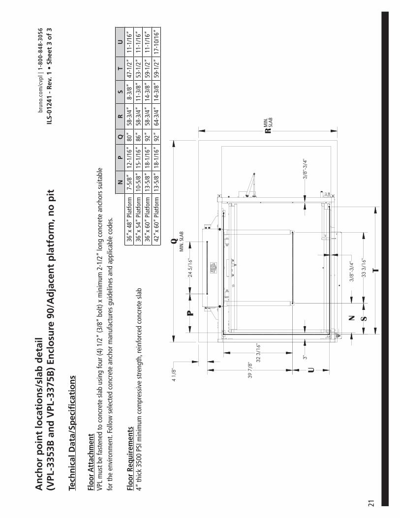
An
cho
r p
oin
t lo
cati
on
s/sl
ab d
etai
l(V
PL-3
353B
an
d V
PL-3
375B
) En
clo
sure
90/
Ad
jace
nt
pla
tfo
rm, n
o p
it
Tech
nic
al D
ata/
Spec
ifica
tio
ns
Floo
r Att
achm
ent
VPL
mus
t be
fast
ened
to c
oncr
ete
slab
usi
ng fo
ur (4
) 1/2
” (3
/8”
bolt)
x m
inim
um 2
-1/2
” lo
ng c
oncr
ete
anch
ors
suita
ble
for t
he e
nviro
nmen
t. Fo
llow
sel
ecte
d co
ncre
te a
ncho
r man
ufac
ture
s gu
idel
ines
and
app
licab
le c
odes
.
Floo
r Re
quir
emen
ts4”
thic
k 35
00 P
SI m
inim
um c
ompr
essi
ve s
tren
gth,
rein
forc
ed c
oncr
ete
slab
NP
QR
ST
U36
”x 4
8” P
latfo
rm7-
5/8”
12-1
/16”
80”
58-3
/4”
8-3/
8”47
-1/2
”11
-1/1
6”36
”x 5
4” P
latfo
rm10
-5/8
”15
-1/1
6”86
”58
-3/4
”11
-3/8
”53
-1/2
”11
-1/1
6”36
”x 6
0” P
latfo
rm13
-5/8
”18
-1/1
6”92
”58
-3/4
”14
-3/8
”59
-1/2
”11
-1/1
6”42
”x 6
0” P
latfo
rm13
-5/8
”18
-1/1
6”92
”64
-3/4
”14
-3/8
”59
-1/2
”17
-10/
16”
3/8"
-3/4
"
3/8"
-3/4
"
3"
24 5
/16"
T
33 3
/16"
P
39 7
/8"
4 1/
8"
32 3
/16"
Q
R
U
SN
ILS-
0124
1 -
Rev
. 1 •
Sh
eet
3 o
f 3
brun
o.co
m/c
vpl |
1-8
00-8
48-3
056

22Lo
w R
ise
Mo
del
s (V
PL-3
353B
an
d V
PL-3
375B
)En
clo
sure
90°
/Ad
jace
nt
Plat
form
, wit
h p
it
Tech
nic
al D
ata/
Spec
ifica
tio
ns
Rate
d lo
ad -
750
lbs
max
Inpu
t po
wer
sou
rce
- D
C ba
tter
y po
wer
ed u
nit:
110
-120
vol
t - 3
Am
p 60
Hz
batt
ery
char
ger
Dri
ve -
DC
batt
ery
pow
ered
uni
t: 1
/2 h
p m
otor
, 175
0 rp
m, 2
4 VD
C, c
ontin
uous
dut
y
Inte
rmed
iate
red
ucti
on: D
ual 4
L st
yle
Poly
-V b
elts
and
pul
leys
, 3.9
4:1
pulle
y re
duct
ion
Fi
nal d
rive
: 1”
dia.
ACM
E sc
rew
w/b
ronz
e nu
t and
bro
nze
safe
ty b
ack
up n
ut
Mot
or c
ontr
olle
r -
DC
batt
ery
pow
ered
uni
t: 2
4 VD
C re
lay
cont
rol
Spee
d -
DC
batt
ery
pow
ered
uni
t: 1
0 ft
per m
inut
e m
axim
um
For
com
ple
te t
ech
nic
al s
pec
ifica
tio
ns,
ple
ase
see
ILS-
0110
0 “V
PL-3
300B
Ser
ies
Co
mm
erci
al V
erti
cal P
latf
orm
Lif
t Te
chn
ical
Sp
ecifi
cati
on
.”
Perf
orm
ance
Sta
nd
ard
s
USA
Foo
d &
Dru
g Ad
min
istr
atio
n: C
lass
II, 5
10(K
) Exe
mpt
, File
No.
890
.393
0 Pr
oduc
t Cod
e: P
CE
ASM
E A1
8.1-
2014
(Sec
tion
2) S
afet
y St
anda
rds
for P
latfo
rm L
ifts
and
Stai
rway
Cha
irlift
sCS
A B3
55-1
5 Li
fts fo
r Per
sons
with
Phy
sica
l Dis
abili
ties
CSA
B44.
1-14
/ASM
E-A1
7.5-
2014
Ele
vato
r and
Esc
alat
or E
quip
men
t
ILS-
0124
2 -
Rev
. 1 •
Sh
eet
1 o
f 3
brun
o.co
m/c
vpl |
1-8
00-8
48-3
056

23
Low
Ris
e M
od
els
(VPL
-335
3B a
nd
VPL
-337
5B)
Encl
osu
re 9
0°/A
dja
cen
t Pl
atfo
rm, w
ith
pit
A
D
C
F
7 1/
4"
M
G
H
K
L B
C LPL
ATF
ORM
DF
GH
JK
LM
36”x
48”
Pla
tform
36-1
/4”
48-1
/4”
10-1
1/16
”55
-1/2
”79
-3/8
”10
2-5/
8”31
-9/1
6”55
-1/4
”36
”x 5
4” P
latfo
rm36
-1/4
”48
-1/4
”13
-11/
16”
61-1
/2”
85-3
/8”
108-
5/8”
31-9
/16”
55-1
/4”
36”x
60”
Pla
tform
36-1
/4”
48-1
/4”
16-1
1/16
”67
-1/2
”91
-3/8
”11
4-5/
8”31
-9/1
6”55
-1/4
”42
”x 6
0” P
latfo
rm42
-1/4
”54
-1/4
”16
-11/
16”
67-1
/2”
91-3
/8”
123-
5/8”
34-9
/16”
61-1
/4”
AB
C M
INC
MA
X
VPL-
3353
B75
-9/1
6”95
”11
”53
”VP
L-33
75B
97-9
/16”
117”
53”
75”
ILS-
0124
2 -
Rev
. 1 •
Sh
eet
2 o
f 3
brun
o.co
m/c
vpl |
1-8
00-8
48-3
056
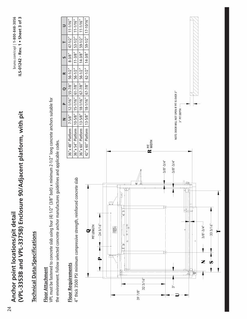
24A
nch
or
po
int
loca
tio
ns/
pit
det
ail
(VPL
-335
3B a
nd
VPL
-337
5B)
Encl
osu
re 9
0/A
dja
cen
t p
latf
orm
, wit
h p
it
Tech
nic
al D
ata/
Spec
ifica
tio
ns
Floo
r Att
achm
ent
VPL
mus
t be
fast
ened
to c
oncr
ete
slab
usi
ng fo
ur (4
) 1/2
” (3
/8”
bolt)
x m
inim
um 2
-1/2
” lo
ng c
oncr
ete
anch
ors
suita
ble
for
the
envi
ronm
ent.
Follo
w s
elec
ted
conc
rete
anc
hor m
anuf
actu
res
guid
elin
es a
nd a
pplic
able
cod
es.
Floo
r Re
quir
emen
ts4”
thic
k 35
00 P
SI m
inim
um c
ompr
essi
ve s
tren
gth,
rein
forc
ed c
oncr
ete
slab
NP
QR
ST
U36
”x 4
8” P
latfo
rm7-
5/8”
12-1
/16”
55-7
/8”
56-1
/2”
8-3/
8”47
-1/2
”11
-1/1
6”36
”x 5
4” P
latfo
rm10
-5/8
”15
-1/1
6”61
-7/8
”56
-1/2
”11
-3/8
”53
-1/2
”11
-1/1
6”36
”x 6
0” P
latfo
rm13
-5/8
”18
-1/1
6”67
-7/8
”56
-1/2
”14
-3/8
”59
-1/2
”11
-1/1
6”42
”x 6
0” P
latfo
rm13
-5/8
”18
-1/1
6”67
-7/8
”62
-1/2
”14
-3/8
”59
-1/2
”17
-10/
16”
3/8"
-3/4
"
3/8"
-3/4
"
3"
24 5
/16"
TQ
R
3/8"
-3/4
"
33 3
/16"
P
39 7
/8" 32
3/1
6"
U
SN
3/8"
-3/4
"
3/8"
-3/4
"
3"
24 5
/16"
TQ
R
3/8"
-3/4
"
33 3
/16"
P
39 7
/8" 32
3/1
6"
U
SN
ILS-
0124
2 -
Rev
. 1 •
Sh
eet
3 o
f 3
brun
o.co
m/c
vpl |
1-8
00-8
48-3
056

25
Tall
Mo
del
s (V
PL-3
310B
, VPL
-331
2B a
nd
VPL
-331
4B)
Encl
osu
re S
ame
Sid
e Pl
atfo
rm, n
o p
itTe
chn
ical
Dat
a/Sp
ecifi
cati
on
s
Rate
d lo
ad -
750
lbs
max
Inpu
t po
wer
sou
rce
- D
C ba
tter
y po
wer
ed u
nit:
110
-120
vol
t - 3
Am
p 60
Hz
batt
ery
char
ger
Dri
ve -
DC
batt
ery
pow
ered
uni
t: 1
hp
mot
or, 1
750
rpm
, 24
VDC,
con
tinuo
us d
uty
In
term
edia
te r
educ
tion
: Dua
l 4L
styl
e Po
ly-V
bel
ts a
nd p
ulle
ys, 3
.94:
1 pu
lley
redu
ctio
n
Fina
l dri
ve: 1
1/4
” A
CME
scre
w w
/bro
nze
nut a
nd b
ronz
e sa
fety
bac
k up
nut
Mot
or c
ontr
olle
r -
DC
batt
ery
pow
ered
uni
t: 2
4 VD
C re
lay
cont
rol
Spee
d -
DC
batt
ery
pow
ered
uni
t: 1
0 ft
per m
inut
e m
axim
um
For
com
ple
te t
ech
nic
al s
pec
ifica
tio
ns,
ple
ase
see
ILS-
0110
0 “V
PL-3
300B
Ser
ies
Co
mm
erci
al V
erti
cal P
latf
orm
Lif
t Te
chn
ical
Sp
ecifi
cati
on
.”
Perf
orm
ance
Sta
nd
ard
s
USA
Foo
d &
Dru
g Ad
min
istr
atio
n: C
lass
II, 5
10(K
) Exe
mpt
, File
No.
890
.393
0 Pr
oduc
t Cod
e: P
CE
ASM
E A1
8.1-
2014
(Sec
tion
2) S
afet
y St
anda
rds
for P
latfo
rm L
ifts
and
Stai
rway
Cha
irlift
sCS
A B3
55-1
5 Li
fts fo
r Per
sons
with
Phy
sica
l Dis
abili
ties
CSA
B44.
1-14
/ASM
E-A1
7.5-
2014
Ele
vato
r and
Esc
alat
or E
quip
men
t
ILS-
0128
9 -
Rev
. 1 •
Sh
eet
1 o
f 3
brun
o.co
m/c
vpl |
1-8
00-8
48-3
056

26
B
K
J
G
H
7 1/
4" FM
L
C
D
A
Tall
Mo
del
s (V
PL-3
310B
, VPL
-331
2B a
nd
VPL
-331
4B)
Encl
osu
re S
ame
Sid
e Pl
atfo
rm, n
o p
it
DF
GH
JK
LM
36”x
48”
Pla
tform
36-1
/4”
48”
10-1
1/16
”55
-1/2
”79
-3/8
”10
2-5/
8”31
-9/1
6”55
-1/4
”36
”x 5
4” P
latfo
rm36
-1/4
”48
”13
-11/
16”
61-1
/2”
85-3
/8”
108-
5/8”
31-9
/16”
55-1
/4”
36”x
60”
Pla
tform
36-1
/4”
48”
16-1
1/16
”67
-1/2
”91
-3/8
”11
4-5/
8”31
-9/1
6”55
-1/4
”42
”x 6
0” P
latfo
rm42
-1/4
”54
”16
-11/
16”
67-1
/2”
91-3
/8”
123-
5/8”
34-9
/16”
61-1
/4”
Mo
del
AB
C M
INC
MA
X
VPL-
3310
B14
8-1/
16”
165”
75”
123”
VPL-
3312
B17
2-1/
16”
189”
75”
147”
VPL-
3314
B19
6-1/
16”
213”
75”
171”
ILS-
0128
9 -
Rev
. 1 •
Sh
eet
2 o
f 3
brun
o.co
m/c
vpl |
1-8
00-8
48-3
056

27
An
cho
r p
oin
t lo
cati
on
s/sl
ab d
etai
l (V
PL-3
310B
, VPL
-331
2B a
nd
VPL
-331
4B)
Encl
osu
re S
ame
Sid
e Pl
atfo
rm, n
o p
it
Tech
nic
al D
ata/
Spec
ifica
tio
ns
Floo
r Att
achm
ent
VPL
mus
t be
fast
ened
to c
oncr
ete
slab
usi
ng fo
ur (4
) 1/2
” (3
/8”
bolt)
x m
inim
um 2
-1/2
” lo
ng c
oncr
ete
anch
ors
suita
ble
for t
he e
nviro
nmen
t. Fo
llow
sel
ecte
d co
ncre
te a
ncho
r m
anuf
actu
res
guid
elin
es a
nd a
pplic
able
cod
es.
Floo
r Re
quir
emen
ts4”
thic
k 35
00 P
SI m
inim
um c
ompr
essi
ve s
tren
gth,
rein
forc
ed c
oncr
ete
slab
24 5
/16"
39 7
/8"
32 3
/16"
33 3
/16"
P
3/8"
-3/4
"
3" U
S N
T
4 1/
8"
R
QM
IN. S
LAB
LAN
DIN
G G
ATE
END
OF
ENCL
OSU
RE
MIN
.SL
AB
NP
QR
ST
U36
”x 4
8” P
latfo
rm7-
5/8”
12-1
/16”
80”
58-9
/16”
8-3/
8”47
-1/2
”10
-15/
16”
36”x
54”
Pla
tform
10-5
/8”
15-1
/16”
86”
58-9
/16”
11-3
/8”
53-1
/2”
10-1
5/16
”36
”x 6
0” P
latfo
rm13
-5/8
”18
-1/1
6”92
”58
-9/1
6”14
-3/8
”59
-1/2
”10
-15/
16”
42”x
60”
Pla
tform
13-5
/8”
18-1
/16”
92”
64-9
/16”
14-3
/8”
59-1
/2”
16-1
5/16
”
ILS-
0128
9 -
Rev
. 1 •
Sh
eet
3 o
f 3
brun
o.co
m/c
vpl |
1-8
00-8
48-3
056

28Ta
ll M
od
els
(VPL
-331
0B, V
PL-3
312B
an
d V
PL-3
314B
)En
clo
sure
Sam
e Si
de
Plat
form
, wit
h p
it
Tech
nic
al D
ata/
Spec
ifica
tio
ns
Rate
d lo
ad -
750
lbs
max
Inpu
t po
wer
sou
rce
- D
C ba
tter
y po
wer
ed u
nit:
110
-120
vol
t - 3
Am
p 60
Hz
batt
ery
char
ger
Dri
ve -
DC
batt
ery
pow
ered
uni
t: 1
hp
mot
or, 1
750
rpm
, 24
VDC,
con
tinuo
us d
uty
In
term
edia
te r
educ
tion
: Dua
l 4L
styl
e Po
ly-V
bel
ts a
nd p
ulle
ys, 3
.94:
1 pu
lley
redu
ctio
n
Fina
l dri
ve: 1
1/4
” A
CME
scre
w w
/bro
nze
nut a
nd b
ronz
e sa
fety
bac
k up
nut
Mot
or c
ontr
olle
r -
DC
batt
ery
pow
ered
uni
t: 2
4 VD
C re
lay
cont
rol
Spee
d -
DC
batt
ery
pow
ered
uni
t: 1
0 ft
per m
inut
e m
axim
um
For
com
ple
te t
ech
nic
al s
pec
ifica
tio
ns,
ple
ase
see
ILS-
0110
0 “V
PL-3
300B
Ser
ies
Co
mm
erci
al V
erti
cal P
latf
orm
Lif
t Te
chn
ical
Sp
ecifi
cati
on
.”
Perf
orm
ance
Sta
nd
ard
s
USA
Foo
d &
Dru
g Ad
min
istr
atio
n: C
lass
II, 5
10(K
) Exe
mpt
, File
No.
890
.393
0 Pr
oduc
t Cod
e: P
CE
ASM
E A1
8.1-
2014
(Sec
tion
2) S
afet
y St
anda
rds
for P
latfo
rm L
ifts
and
Stai
rway
Cha
irlift
sCS
A B3
55-1
5 Li
fts fo
r Per
sons
with
Phy
sica
l Dis
abili
ties
CSA
B44.
1-14
/ASM
E-A1
7.5-
2014
Ele
vato
r and
Esc
alat
or E
quip
men
t
ILS-
0129
0 -
Rev
. 1 •
Sh
eet
1 o
f 3
brun
o.co
m/c
vpl |
1-8
00-8
48-3
056

29
Tall
Mo
del
s (V
PL-3
310B
, VPL
-331
2B a
nd
VPL
-331
4B)
Encl
osu
re S
ame
Sid
e Pl
atfo
rm, w
ith
pit
B
SILL
PLA
TEO
F U
PPER
LAN
DIN
GG
ATE
KG
7 1/
4" FM
H
L
CIRC
UIT
BREA
KER
BOX
3" PIT
C
D
NO
TE: D
OO
R W
ILL
NO
T O
PEN
IF P
IT IS
OVE
R 3"
UPP
ER L
ANDI
NG
GAT
E N
OT
SHO
WN
TOP
OF
PLAT
FORM
DECK
A
LEFT
OR
RIG
HT H
AND
SWIN
G L
ANDI
NG
GAT
ES
FLO
OR
TOFL
OO
R
C L P
LATF
ORM
LEFT
OR
RIG
HTHA
ND
SWIN
GDO
OR
DF
GH
KL
M36
”x 4
8” P
latfo
rm36
-1/4
”48
”10
-11/
16”
55-1
/2”
102-
5/8”
31-9
/16”
55-1
/4”
36”x
54”
Pla
tform
36-1
/4”
48”
13-1
1/16
”61
-1/2
”10
8-5/
8”31
-9/1
6”55
-1/4
”36
”x 6
0” P
latfo
rm36
-1/4
”48
”16
-11/
16”
67-1
/2”
114-
5/8”
31-9
/16”
55-1
/4”
42”x
60”
Pla
tform
42-1
/4”
54”
16-1
1/16
”67
-1/2
”12
3-5/
8”34
-9/1
6”61
-1/4
”
Mo
del
AB
C M
INC
MA
X
VPL-
3310
B14
8-1/
16”
165”
75”
123”
VPL-
3312
B17
2-1/
16”
189”
75”
147”
VPL-
3314
B19
6-1/
16”
213”
75”
171”
ILS-
0129
0 -
Rev
. 1 •
Sh
eet
2 o
f 3
brun
o.co
m/c
vpl |
1-8
00-8
48-3
056

30A
nch
or
po
int
loca
tio
ns/
pit
det
ail
(VPL
-331
0B, V
PL-3
312B
an
d V
PL-3
314B
)En
clo
sure
Sam
e Si
de
Plat
form
, wit
h p
it
Tech
nic
al D
ata/
Spec
ifica
tio
ns
Floo
r Att
achm
ent
VPL
mus
t be
fast
ened
to c
oncr
ete
slab
usi
ng fo
ur (4
) 1/2
” (3
/8”
bolt)
x m
inim
um 2
-1/2
” lo
ng c
oncr
ete
anch
ors
suita
ble
for
the
envi
ronm
ent.
Follo
w s
elec
ted
conc
rete
anc
hor m
anuf
actu
res
guid
elin
es a
nd a
pplic
able
cod
es.
Floo
r Re
quir
emen
ts4”
thic
k 35
00 P
SI m
inim
um c
ompr
essi
ve s
tren
gth,
rein
forc
ed c
oncr
ete
slab
NP
QR
ST
U36
”x 4
8” P
latfo
rm7-
5/8”
12-1
/16”
55-7
/8”
57”
8-3/
8”47
-1/2
”10
-15/
16”
36”x
54”
Pla
tform
10-5
/8”
15-1
/16”
61-7
/8”
57”
11-3
/8”
53-1
/2”
10-1
5/16
”36
”x 6
0” P
latfo
rm13
-5/8
”18
-1/1
6”67
-7/8
”57
”14
-3/8
”59
-1/2
”10
-15/
16”
42”x
60”
Pla
tform
13-5
/8”
18-1
/16”
67-7
/8”
63”
14-3
/8”
59-1
/2”
16-1
5/16
”
24 5
/16"
39 7
/8"
33 3
/16"
P
3" U
3/8"
-3/4
"
ST
N
32 3
/16"
R
4 1/
8"
Q
3"
24 5
/16"
39 7
/8"
33 3
/16"
P
3" U
3/8"
-3/4
"
ST
N
32 3
/16"
R
4 1/
8"
Q
3"
ILS-
0129
0 -
Rev
. 1 •
Sh
eet
3 o
f 3
brun
o.co
m/c
vpl |
1-8
00-8
48-3
056

31
Tall
Mo
del
s (V
PL-3
310B
, VPL
-331
2B a
nd
VPL
-331
4B)
Encl
osu
re S
trai
gh
t Th
rou
gh
Pla
tfo
rm, n
o p
itTe
chn
ical
Dat
a/Sp
ecifi
cati
on
s
Rate
d lo
ad -
750
lbs
max
Inpu
t po
wer
sou
rce
- D
C ba
tter
y po
wer
ed u
nit:
110
-120
vol
t - 3
Am
p 60
Hz
batt
ery
char
ger
Dri
ve -
DC
batt
ery
pow
ered
uni
t: 1
hp
mot
or, 1
750
rpm
, 24
VDC,
con
tinuo
us d
uty
In
term
edia
te r
educ
tion
: Dua
l 4L
styl
e Po
ly-V
bel
ts a
nd p
ulle
ys, 3
.94:
1 pu
lley
redu
ctio
n
Fina
l dri
ve: 1
1/4
” A
CME
scre
w w
/bro
nze
nut a
nd b
ronz
e sa
fety
bac
k up
nut
Mot
or c
ontr
olle
r -
DC
batt
ery
pow
ered
uni
t: 2
4 VD
C re
lay
cont
rol
Spee
d -
DC
batt
ery
pow
ered
uni
t: 1
0 ft
per m
inut
e m
axim
um
For
com
ple
te t
ech
nic
al s
pec
ifica
tio
ns,
ple
ase
see
ILS-
0110
0 “V
PL-3
300B
Ser
ies
Co
mm
erci
al V
erti
cal P
latf
orm
Lif
t Te
chn
ical
Sp
ecifi
cati
on
.”
Perf
orm
ance
Sta
nd
ard
s
USA
Foo
d &
Dru
g Ad
min
istr
atio
n: C
lass
II, 5
10(K
) Exe
mpt
, File
No.
890
.393
0 Pr
oduc
t Cod
e: P
CE
ASM
E A1
8.1-
2014
(Sec
tion
2) S
afet
y St
anda
rds
for P
latfo
rm L
ifts
and
Stai
rway
Cha
irlift
sCS
A B3
55-1
5 Li
fts fo
r Per
sons
with
Phy
sica
l Dis
abili
ties
CSA
B44.
1-14
/ASM
E-A1
7.5-
2014
Ele
vato
r and
Esc
alat
or E
quip
men
t
ILS-
0127
7 -
Rev
. 0 •
Sh
eet
1 o
f 3
brun
o.co
m/c
vpl |
1-8
00-8
48-3
056

32Ta
ll M
od
els
(VPL
-331
0B, V
PL-3
312B
an
d V
PL-3
314B
)En
clo
sure
Str
aig
ht
Thro
ug
h P
latf
orm
, no
pit
B
GK
HJ
7 1/
4" FM
L
A
C
D
DF
GH
JK
LM
36”x
48”
Pla
tform
36-1
/4”
48”
8-1/
4”53
”76
-13/
16”
91-1
/8”
31-9
/16”
55-1
/4”
36”x
54”
Pla
tform
36-1
/4”
48”
11-1
/16”
59”
82-1
3/16
”97
-1/8
”31
-9/1
6”55
-1/4
”36
”x 6
0” P
latfo
rm36
-1/4
”48
”14
-1/1
6”65
”88
-13/
16”
103-
1/8”
31-9
/16”
55-1
/4”
42”x
60”
Pla
tform
42-1
/4”
54”
14-1
/16”
65”
88-1
3/16
”11
2-1/
8”34
-9/1
6”61
-1/4
”
Mo
del
AB
C M
INC
MA
X
VPL-
3310
B14
8-1/
16”
165”
75”
123”
VPL-
3312
B17
2-1/
16”
189”
75”
147”
VPL-
3314
B19
6-1/
16”
213”
75”
171”
ILS-
0127
7 -
Rev
. 0 •
Sh
eet
2 o
f 3
brun
o.co
m/c
vpl |
1-8
00-8
48-3
056

33
An
cho
r p
oin
t lo
cati
on
s/sl
ab d
etai
l(V
PL-3
310B
, VPL
-331
2B a
nd
VPL
-331
4B)
Encl
osu
re S
ame
Sid
e Pl
atfo
rm, n
o p
it
Tech
nic
al D
ata/
Spec
ifica
tio
ns
Floo
r Att
achm
ent
VPL
mus
t be
fast
ened
to c
oncr
ete
slab
usi
ng fo
ur (4
) 1/2
” (3
/8”
bolt)
x m
inim
um 2
-1/2
” lo
ng c
oncr
ete
anch
ors
suita
ble
for t
he e
nviro
nmen
t. Fo
llow
sel
ecte
d co
ncre
te
anch
or m
anuf
actu
res
guid
elin
es a
nd a
pplic
able
cod
es.
Floo
r Re
quir
emen
ts4”
thic
k 35
00 P
SI m
inim
um c
ompr
essi
ve s
tren
gth,
rein
forc
ed c
oncr
ete
slab
NP
QR
ST
U36
”x 4
8” P
latfo
rm7-
5/8”
12-1
/16”
76”
58-9
/16”
5-15
/16”
45”
10-1
5/16
”36
”x 5
4” P
latfo
rm10
-5/8
”15
-1/1
6”82
”58
-9/1
6”8-
15/1
6”51
”10
-15/
16”
36”x
60”
Pla
tform
13-5
/8”
18-1
/16”
88”
58-9
/16”
11-1
5/16
”57
”10
-15/
16”
42”x
60”
Pla
tform
13-5
/8”
18-1
/16”
88”
64-9
/16”
11-1
5/16
”56
”16
-15/
16”
24 5
/16"
P
39 7
/8"
3/8"
-3/4
"
32 3
/16"
U
3/8"
-3/4
"
ST
N33
3/1
6"
Q
4 1/
8"
R
MIN
. SLA
B
LAN
DIN
G G
ATE
END
OF
ENCL
OSU
RE
MIN
.SL
AB
ILS-
0127
7 -
Rev
. 0 •
Sh
eet
3 o
f 3
brun
o.co
m/c
vpl |
1-8
00-8
48-3
056

34Ta
ll M
od
els
(VPL
-331
0B, V
PL-3
312B
an
d V
PL-3
314B
)En
clo
sure
Str
aig
ht
Thro
ug
h P
latf
orm
, wit
h p
it
Tech
nic
al D
ata/
Spec
ifica
tio
ns
Rate
d lo
ad
- 75
0 lb
s m
ax
Inpu
t po
wer
sou
rce
- D
C ba
tter
y po
wer
ed u
nit:
110
-120
vol
t - 3
Am
p 60
Hz
batt
ery
char
ger
Dri
ve -
DC
batt
ery
pow
ered
uni
t: 1
hp
mot
or, 1
750
rpm
, 24
VDC,
con
tinuo
us d
uty
In
term
edia
te r
educ
tion
: Dua
l 4L
styl
e Po
ly-V
bel
ts a
nd p
ulle
ys, 3
.94:
1 pu
lley
redu
ctio
n
Fina
l dri
ve: 1
1/4
” A
CME
scre
w w
/bro
nze
nut a
nd b
ronz
e sa
fety
bac
k up
nut
Mot
or c
ontr
olle
r -
DC
batt
ery
pow
ered
uni
t: 2
4 VD
C re
lay
cont
rol
Spee
d -
DC
batt
ery
pow
ered
uni
t: 1
0 ft
per m
inut
e m
axim
um
For
com
ple
te t
ech
nic
al s
pec
ifica
tio
ns,
ple
ase
see
ILS-
0110
0 “V
PL-3
300B
Ser
ies
Co
mm
erci
al V
erti
cal P
latf
orm
Lif
t Te
chn
ical
Sp
ecifi
cati
on
.”
Perf
orm
ance
Sta
nd
ard
s
USA
Foo
d &
Dru
g Ad
min
istr
atio
n: C
lass
II, 5
10(K
) Exe
mpt
, File
No.
890
.393
0 Pr
oduc
t Cod
e: P
CE
ASM
E A1
8.1-
2014
(Sec
tion
2) S
afet
y St
anda
rds
for P
latfo
rm L
ifts
and
Stai
rway
Cha
irlift
sCS
A B3
55-1
5 Li
fts fo
r Per
sons
with
Phy
sica
l Dis
abili
ties
CSA
B44.
1-14
/ASM
E-A1
7.5-
2014
Ele
vato
r and
Esc
alat
or E
quip
men
t
ILS-
0127
8 -
Rev
. 2 •
Sh
eet
1 o
f 3
brun
o.co
m/c
vpl |
1-8
00-8
48-3
056

35
Tall
Mo
del
s (V
PL-3
310B
, VPL
-331
2B a
nd
VPL
-331
4B)
Encl
osu
re S
trai
gh
t Th
rou
gh
Pla
tfo
rm, w
ith
pit
B
GK
H
7 1/
4" FM
L
A
C
D
DF
GH
KL
M36
”x 4
8” P
latfo
rm36
-1/4
”48
”8-
1/4”
53”
91-1
/8”
31-9
/16”
55-1
/4”
36”x
54”
Pla
tform
36-1
/4”
48”
11-1
/4”
59”
97-1
/8”
31-9
/16”
55-1
/4”
36”x
60”
Pla
tform
36-1
/4”
48”
14-1
/4”
65”
103-
1/8”
31-9
/16”
55-1
/4”
42”x
60”
Pla
tform
42-1
/4”
54”
14-1
/4”
65”
112-
1/8”
34-9
/16”
61-1
/4”
Mo
del
AB
C M
INC
MA
X
VPL-
3310
B14
8-1/
16”
165”
75”
123”
VPL-
3312
B17
2-1/
16”
189”
75”
147”
VPL-
3314
B19
6-1/
16”
213”
75”
171”
ILS-
0127
8 -
Rev
. 2 •
Sh
eet
2 o
f 3
brun
o.co
m/c
vpl |
1-8
00-8
48-3
056

36A
nch
or
po
int
loca
tio
ns/
pit
det
ail
(VPL
-331
0B, V
PL-3
312B
an
d V
PL-3
314B
)En
clo
sure
Str
aig
ht
thro
ug
h P
latf
orm
, wit
h p
it
Tech
nic
al D
ata/
Spec
ifica
tio
ns
Floo
r Att
achm
ent
VPL
mus
t be
fast
ened
to c
oncr
ete
slab
usi
ng fo
ur (4
) 1/2
” (3
/8”
bolt)
x m
inim
um 2
-1/2
” lo
ng c
oncr
ete
anch
ors
suita
ble
for
the
envi
ronm
ent.
Follo
w s
elec
ted
conc
rete
anc
hor m
anuf
actu
res
guid
elin
es a
nd a
pplic
able
cod
es.
Floo
r Re
quir
emen
ts4”
thic
k 35
00 P
SI m
inim
um c
ompr
essi
ve s
tren
gth,
rein
forc
ed c
oncr
ete
slab
NP
QR
ST
U36
”x 4
8” P
latfo
rm7-
5/8”
12-1
/16”
53-3
/8”
57”
5-15
/16”
45”
10-1
5/16
”36
”x 5
4” P
latfo
rm10
-5/8
”15
-1/1
6”59
-3/8
”57
”8-
15/1
6”51
”10
-15/
16”
36”x
60”
Pla
tform
13-5
/8”
18-1
/16”
65-3
/8”
57”
11-1
5/16
”57
”10
-15/
16”
42”x
60”
Pla
tform
13-5
/8”
18-1
/16”
65-3
/8”
63”
11-1
5/16
”56
”16
-15/
16”
24 5
/16"
P
39 7
/8"
3/8"
-3/4
"
32 3
/16"
U
3/8"
-3/4
"
ST
N33
3/1
6"
R
Q24
5/1
6"P
39 7
/8"
3/8"
-3/4
"
32 3
/16"
U
3/8"
-3/4
"
ST
N33
3/1
6"
R
Q
ILS-
0127
8 -
Rev
. 2 •
Sh
eet
3 o
f 3
brun
o.co
m/c
vpl |
1-8
00-8
48-3
056
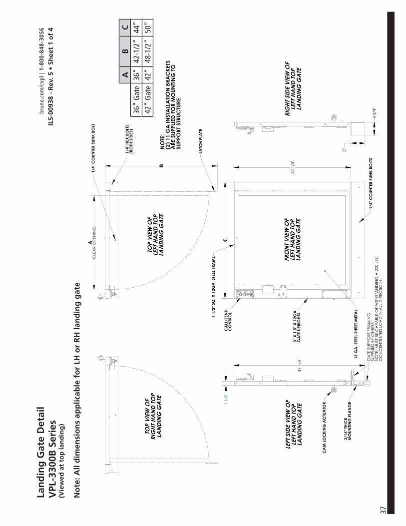
37
Lan
din
g G
ate
Det
ail
VPL
-330
0B S
erie
s(V
iew
ed a
t to
p la
nd
ing
)
No
te: A
ll d
imen
sio
ns
app
licab
le f
or
LH o
r R
H la
nd
ing
gat
e
CA
AB
C36
” G
ate
36”
42-1
/2”
44”
42”
Gat
e42
”48
-1/2
”50
”
ILS-
0093
8 -
Rev
. 5 •
Sh
eet
1 o
f 4
brun
o.co
m/c
vpl |
1-8
00-8
48-3
056
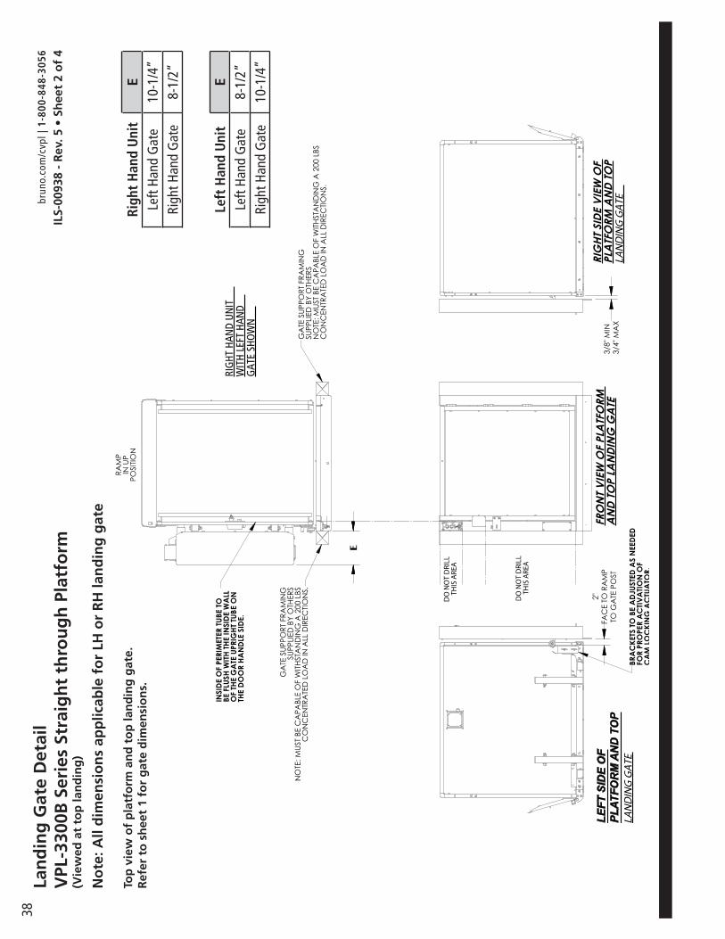
38
DO
NO
T D
RILL
THIS
ARE
A
E
DO
NO
T D
RILL
THIS
ARE
A
Righ
t H
and
Uni
tE
Left
Hand
Gat
e10
-1/4
”Ri
ght H
and
Gat
e8-
1/2”
Left
Han
d U
nit
ELe
ft Ha
nd G
ate
8-1/
2”Ri
ght H
and
Gat
e10
-1/4
”
Lan
din
g G
ate
Det
ail
VPL
-330
0B S
erie
s St
raig
ht
thro
ug
h P
latf
orm
(V
iew
ed a
t to
p la
nd
ing
)
No
te: A
ll d
imen
sio
ns
app
licab
le f
or
LH o
r R
H la
nd
ing
gat
e
Top
vie
w o
f p
latf
orm
an
d t
op
lan
din
g g
ate.
Ref
er t
o s
hee
t 1
for
gat
e d
imen
sio
ns.
ILS-
0093
8 -
Rev
. 5 •
Sh
eet
2 o
f 4
brun
o.co
m/c
vpl |
1-8
00-8
48-3
056

39
Lan
din
g G
ate
Det
ail
VPL
-330
0B S
erie
s 90
° /
Ad
jace
nt
Exit
Pla
tfo
rm(V
iew
ed a
t to
p la
nd
ing
)
RIG
HT H
AND
UN
ITW
ITH
LEFT
HAN
DG
ATE
SHO
WN
DO
NO
T D
RILL
THIS
ARE
A
DO
NO
T D
RILL
THIS
ARE
A
Top
vie
w o
f p
latf
orm
an
d t
op
la
nd
ing
gat
e.R
efer
to
sh
eet
1 fo
r g
ate
dim
ensi
on
s.
ILS-
0093
8 -
Rev
. 5 •
Sh
eet
3 o
f 4
brun
o.co
m/c
vpl |
1-8
00-8
48-3
056

40La
nd
ing
Gat
e D
etai
lV
PL-3
300B
Ser
ies
Sam
e Si
de
Plat
form
(Vie
wed
at
top
lan
din
g)
E
LAN
DIN
G G
ATE
DO
NO
T D
RILL
THIS
ARE
A
DO
NO
T D
RILL
THIS
ARE
A
Top
vie
w o
f p
latf
orm
an
d t
op
lan
din
g g
ate.
Ref
er t
o s
hee
t 1
for
gat
e d
imen
sio
ns.
ILS-
0093
8 -
Rev
. 5 •
Sh
eet
4 o
f 4
brun
o.co
m/c
vpl |
1-8
00-8
48-3
056
Righ
t H
and
Uni
tE
Left
Hand
Gat
e8-
1/2”
Righ
t Han
d G
ate
10-1
/4”
Left
Han
d U
nit
ELe
ft Ha
nd G
ate
10-1
/4”
Righ
t Han
d G
ate
8-1/
2”

41
------
-
ILS-
0119
4 -
Rev
. 1 •
Sh
eet
1 o
f 5
brun
o.co
m/c
vpl |
1-8
00-8
48-3
056
Des
crip
tio
n‘A
’‘B
’‘C
’‘D
’‘E
’Flu
sh m
ount
36”
alum
inum
doo
r36
”42
”44
”33
-3/8
”38
-1/8
”Flu
sh m
ount
45”
alum
inum
doo
r45
”51
”53
”42
-3/8
”47
-1/8
”
Note
s:1.
Two
piec
es o
f ver
tical
fram
e tri
m is
inclu
ded.
Trim
can
be u
sed
as n
eede
d w
hen
insta
lling
the
door
.
2. D
ealer
to su
pply
mou
ntin
g ha
rdw
are
(i.e.
scre
ws,
anch
ors).
3. Pa
nel in
sert
mat
eria
l is e
ither
clea
r acr
ylic o
r bro
nze
acry
lic. P
anels
are
ship
ped
with
a p
rote
ctive
pap
er
to
be
rem
oved
by i
nsta
ller
Flu
sh m
ou
nt
alu
min
um
do
or
det
ail -
LH
Sw
ing
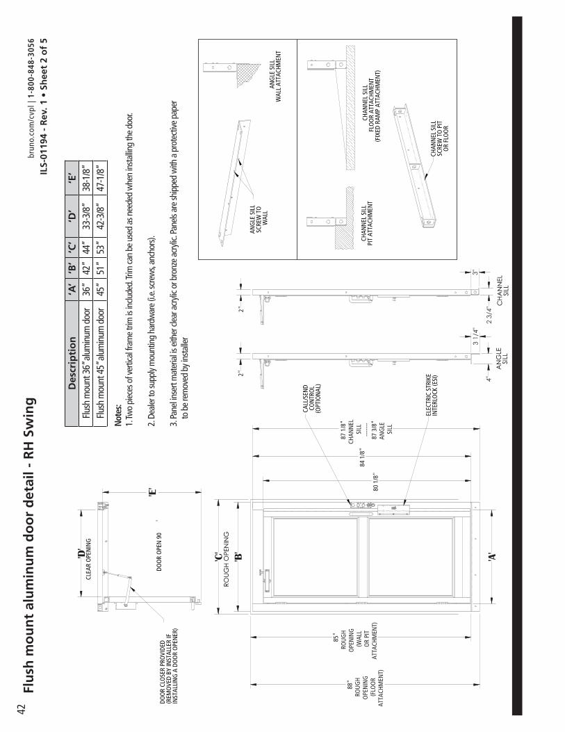
42
ILS-
0119
4 -
Rev
. 1 •
Sh
eet
2 o
f 5
brun
o.co
m/c
vpl |
1-8
00-8
48-3
056
Des
crip
tio
n‘A
’‘B
’‘C
’‘D
’‘E
’Flu
sh m
ount
36”
alum
inum
doo
r36
”42
”44
”33
-3/8
”38
-1/8
”Flu
sh m
ount
45”
alum
inum
doo
r45
”51
”53
”42
-3/8
”47
-1/8
”
Note
s:1.
Two
piec
es o
f ver
tical
fram
e tri
m is
inclu
ded.
Trim
can
be u
sed
as n
eede
d w
hen
insta
lling
the
door
.
2. D
ealer
to su
pply
mou
ntin
g ha
rdw
are
(i.e.
scre
ws,
anch
ors).
3. Pa
nel in
sert
mat
eria
l is e
ither
clea
r acr
ylic o
r bro
nze
acry
lic. P
anels
are
ship
ped
with
a p
rote
ctive
pap
er
to
be
rem
oved
by i
nsta
ller
Flu
sh m
ou
nt
alu
min
um
do
or
det
ail -
RH
Sw
ing
ELEC
TRIC
STR
IKE
INTE
RLO
CK (E
SI)
CALL
/SEN
DCO
NTR
OL
(OPT
ION
AL)
3 1/
4"
4"
3"
2 3/
4"A
NG
LESI
LLC
HAN
NEL
SILL
ROUG
H O
PEN
ING
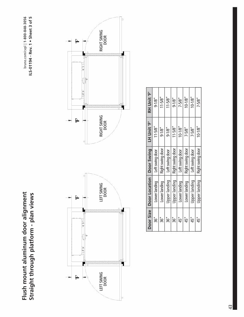
43
ILS-
0119
4 -
Rev
. 1 •
Sh
eet
3 o
f 5
brun
o.co
m/c
vpl |
1-8
00-8
48-3
056
Do
or
Size
Do
or
Loca
tio
nD
oo
r Sw
ing
LH U
nit
‘F’
RH
Un
it ‘F
’36
”Lo
wer
land
ing
Left
swin
g do
or11
-5/8
”9-
1/8”
36”
Low
er la
ndin
gRi
ght s
win
g do
or9-
1/8”
11-5
/8”
36”
Upp
er la
ndin
gLe
ft sw
ing
door
9-1/
8”11
-5/8
”36
”U
pper
land
ing
Righ
t sw
ing
door
11-5
/8”
9-1/
8”45
”Lo
wer
land
ing
Left
swin
g do
or10
-1/8
”7-
5/8”
45”
Low
er la
ndin
gRi
ght s
win
g do
or7-
5/8”
10-1
/8”
45”
Upp
er la
ndin
gLe
ft sw
ing
door
7-5/
8”10
-1/8
”45
”U
pper
land
ing
Righ
t sw
ing
door
10-1
/8”
7-5/
8”
Flu
sh m
ou
nt
alu
min
um
do
or
alig
nm
ent
Stra
igh
t th
rou
gh
pla
tfo
rm -
pla
n v
iew
s

44
ILS-
0119
4 -
Rev
. 1 •
Sh
eet
4 o
f 5
brun
o.co
m/c
vpl |
1-8
00-8
48-3
056
Plat
form
Siz
eD
oo
r Si
zeD
oo
r Lo
cati
on
Do
or
Swin
gLH
Un
it ‘G
’R
H U
nit
‘G’
36”
36”
Low
er la
ndin
gLe
ft sw
ing
door
11-5
/8”
9-1/
8”36
”36
”Lo
wer
land
ing
Righ
t sw
ing
door
9-1/
8”11
-5/8
”36
”45
”U
pper
land
ing
Left
swin
g do
orFlu
sh1”
36”
45”
Upp
er la
ndin
gRi
ght s
win
g do
or1”
Flush
42”
45”
Low
er la
ndin
gLe
ft sw
ing
door
10-1
/8”
7-5/
8”42
”45
”Lo
wer
land
ing
Righ
t sw
ing
door
7-5/
8”10
-5/8
”42
”45
”U
pper
land
ing
Left
swin
g do
orFlu
sh1”
42”
45”
Upp
er la
ndin
gRi
ght s
win
g do
or1”
Flush
Flu
sh m
ou
nt
alu
min
um
do
or
alig
nm
ent
90°/
Ad
jace
nt
exit
pla
tfo
rm-
pla
n v
iew
s

45
ILS-
0119
4 -
Rev
. 1 •
Sh
eet
5 o
f 5
brun
o.co
m/c
vpl |
1-8
00-8
48-3
056
Flu
sh m
ou
nt
alu
min
um
do
or
alig
nm
ent
Sam
e si
de
pla
tfo
rm -
Pla
n v
iew
s
Do
or
Size
Do
or
Loca
tio
nD
oo
r Sw
ing
LH U
nit
‘H’
RH
Un
it ‘H
’36
”Lo
wer
land
ing
Left
swin
g do
or11
-5/8
”9-
1/8”
36”
Low
er la
ndin
gRi
ght s
win
g do
or9-
1/8”
11-5
/8”
36”
Upp
er la
ndin
gLe
ft sw
ing
door
11-5
/8”
9-1/
8”36
”U
pper
land
ing
Righ
t sw
ing
door
9-1/
8”11
-5/8
”45
”Lo
wer
land
ing
Left
swin
g do
or10
-1/8
”7-
5/8”
45”
Low
er la
ndin
gRi
ght s
win
g do
or7-
5/8”
10-5
/8”
45”
Upp
er la
ndin
gLe
ft sw
ing
door
10-1
/8”
7-5/
8”45
”U
pper
land
ing
Righ
t sw
ing
door
7-5/
8”10
-1/8
”

46
1-800-848-3056 | bruno.com/cvpl
Bruno Independent Living Aids, Inc.1780 Executive Drive, Oconomowoc, WI 53066
www.bruno.com
© Bruno Independent Living Aids, Inc. 2016