Bruciatori di gas ad aria soffiata Gebläse - Gasbrenner ... (4).pdf · NOTA: In conformità con...
44
Istruzioni per installazione, uso e manutenzione Montage und Bedienungs Anleitung Installation, use and maintenance instructions Manuel d’entretien Bruciatori di gas ad aria soffiata Gebläse - Gasbrenner Blown type gas burners Brûleurs gaz à air soufflé 2915527 (4) CODICE - CODE MODELLO - MODELL MODEL - MODELE TIPO - TYP TYPE 3781010 RS 28/M 824 T1 3781011 RS 28/M 824 T1 3781410 RS 38/M 825 T1 3781411 RS 38/M 825 T1 3781610 RS 50/M 826 T1 3781611 RS 50/M 826 T1 I D GB F Funzionamento bistadio progressivo o modulante Zweistufig gleitender oder modulierender Betrieb Progressive two-stage or modulating operation Fonctionnement à deux allures progressives ou modulant
Transcript of Bruciatori di gas ad aria soffiata Gebläse - Gasbrenner ... (4).pdf · NOTA: In conformità con...

Istruzioni per installazione, uso e manutenzioneMontage und Bedienungs AnleitungInstallation, use and maintenance instructionsManuel d’entretien
Bruciatori di gas ad aria soffiataGebläse - GasbrennerBlown type gas burnersBrûleurs gaz à air soufflé
2915527 (4)
CODICE - CODEMODELLO - MODELL
MODEL - MODELETIPO - TYP
TYPE
3781010 RS 28/M 824 T1
3781011 RS 28/M 824 T1
3781410 RS 38/M 825 T1
3781411 RS 38/M 825 T1
3781610 RS 50/M 826 T1
3781611 RS 50/M 826 T1
I
D
GB
F
Funzionamento bistadio progressivo o modulanteZweistufig gleitender oder modulierender BetriebProgressive two-stage or modulating operationFonctionnement à deux allures progressives ou modulant

3
INDICE
DATI TECNICI
. . . . . . . . . . . . . . . . . . . . . . . . . . . . . . . . . pagina
4
Versioni costruttive . . . . . . . . . . . . . . . . . . . . . . . . . . . . . . . . . . . . 4Accessori . . . . . . . . . . . . . . . . . . . . . . . . . . . . . . . . . . . . . . . . . . . 4Descrizione bruciatore . . . . . . . . . . . . . . . . . . . . . . . . . . . . . . . . . 8Imballo - Peso. . . . . . . . . . . . . . . . . . . . . . . . . . . . . . . . . . . . . . . . 8Ingombro . . . . . . . . . . . . . . . . . . . . . . . . . . . . . . . . . . . . . . . . . . . 8Corredo . . . . . . . . . . . . . . . . . . . . . . . . . . . . . . . . . . . . . . . . . . . . 8Campi di lavoro. . . . . . . . . . . . . . . . . . . . . . . . . . . . . . . . . . . . . . 10Caldaia di prova . . . . . . . . . . . . . . . . . . . . . . . . . . . . . . . . . . . . . 10Caldaie commerciali . . . . . . . . . . . . . . . . . . . . . . . . . . . . . . . . . . 10Pressione gas. . . . . . . . . . . . . . . . . . . . . . . . . . . . . . . . . . . . . . . 12
INSTALLAZIONE. . . . . . . . . . . . . . . . . . . . . . . . . . . . . . . . . . . . 14
Piastra caldaia . . . . . . . . . . . . . . . . . . . . . . . . . . . . . . . . . . . . . . 14Lunghezza boccaglio . . . . . . . . . . . . . . . . . . . . . . . . . . . . . . . . . 14Fissaggio del bruciatore alla caldaia . . . . . . . . . . . . . . . . . . . . . 14Regolazione testa di combustione . . . . . . . . . . . . . . . . . . . . . . . 16Linea alimentazione gas. . . . . . . . . . . . . . . . . . . . . . . . . . . . . . . 18Impianto elettrico . . . . . . . . . . . . . . . . . . . . . . . . . . . . . . . . . . . . 20Regolazioni prima dell’accensione . . . . . . . . . . . . . . . . . . . . . . . 26Servomotore. . . . . . . . . . . . . . . . . . . . . . . . . . . . . . . . . . . . . . . . 26Avviamento bruciatore . . . . . . . . . . . . . . . . . . . . . . . . . . . . . . . . 26Accensione bruciatore . . . . . . . . . . . . . . . . . . . . . . . . . . . . . . . . 26Regolazione bruciatore: . . . . . . . . . . . . . . . . . . . . . . . . . . . . . . . 281 - Potenza all’accensione . . . . . . . . . . . . . . . . . . . . . . . . . . . . . 282 - Potenza MAX . . . . . . . . . . . . . . . . . . . . . . . . . . . . . . . . . . . . 283 - Potenza MIN . . . . . . . . . . . . . . . . . . . . . . . . . . . . . . . . . . . . . 304 - Potenze intermedie . . . . . . . . . . . . . . . . . . . . . . . . . . . . . . . . 305 - Pressostato aria . . . . . . . . . . . . . . . . . . . . . . . . . . . . . . . . . . 326 - Pressostato gas di massima . . . . . . . . . . . . . . . . . . . . . . . . . 327 - Pressostato gas di minima . . . . . . . . . . . . . . . . . . . . . . . . . . 32Controllo presenza fiamma . . . . . . . . . . . . . . . . . . . . . . . . . . . . 32Funzionamento bruciatore . . . . . . . . . . . . . . . . . . . . . . . . . . . . . 34Controlli finali . . . . . . . . . . . . . . . . . . . . . . . . . . . . . . . . . . . . . . . 36Manutenzione. . . . . . . . . . . . . . . . . . . . . . . . . . . . . . . . . . . . . . . 36Inconvenienti - Cause - Rimedi . . . . . . . . . . . . . . . . . . . . . . . . . 38
Avvertenza
Le figure richiamate nel testo sono così indicate:1)(A) =Particolare 1 della figura A nella stessa pagina del testo;1)(A)p.8 =Particolare 1 della figura A riportata a pagina 8.
NOTA:
In conformità con la Direttiva Rendimento 92/42/CEE,l’applicazione del bruciatore alla caldaia, la regolazione e il col-laudo, devono essere eseguiti nell’osservanza del manualed’istruzione della caldaia stessa, compreso il controllo della con-centrazione di CO e CO
2
nei fumi, della loro temperatura e diquella media dell’acqua della caldaia.
I
INHALT
TECHNISCHE ANGABEN
. . . . . . . . . . . . . . . . . . . . . . . . . Seite
5
Bauvarianten . . . . . . . . . . . . . . . . . . . . . . . . . . . . . . . . . . . . . . . . . 5Zubehörteile . . . . . . . . . . . . . . . . . . . . . . . . . . . . . . . . . . . . . . . . . 5Brennerbeschreibung . . . . . . . . . . . . . . . . . . . . . . . . . . . . . . . . . . 9Verpackung - Gewicht . . . . . . . . . . . . . . . . . . . . . . . . . . . . . . . . . . 9Abmessungen . . . . . . . . . . . . . . . . . . . . . . . . . . . . . . . . . . . . . . . . 9Ausstattung . . . . . . . . . . . . . . . . . . . . . . . . . . . . . . . . . . . . . . . . . . 9Regelbereiche . . . . . . . . . . . . . . . . . . . . . . . . . . . . . . . . . . . . . . . 11Prüfkessel . . . . . . . . . . . . . . . . . . . . . . . . . . . . . . . . . . . . . . . . . . 11Handelsübliche Kessel . . . . . . . . . . . . . . . . . . . . . . . . . . . . . . . . 11Gasdruck . . . . . . . . . . . . . . . . . . . . . . . . . . . . . . . . . . . . . . . . . . . 13
INSTALLATION. . . . . . . . . . . . . . . . . . . . . . . . . . . . . . . . . . . . . . 15
Kesselplatte . . . . . . . . . . . . . . . . . . . . . . . . . . . . . . . . . . . . . . . . . 15Flammrohrlänge . . . . . . . . . . . . . . . . . . . . . . . . . . . . . . . . . . . . . 15Befestigung des Brenners am Heizkessel. . . . . . . . . . . . . . . . . . 15Einstellung des Flammkopfs . . . . . . . . . . . . . . . . . . . . . . . . . . . . 17Gaszuleitung . . . . . . . . . . . . . . . . . . . . . . . . . . . . . . . . . . . . . . . . 19Elektroanlage . . . . . . . . . . . . . . . . . . . . . . . . . . . . . . . . . . . . . . . 21Einstellungen vor der Zündung . . . . . . . . . . . . . . . . . . . . . . . . . . 27Stellantrieb . . . . . . . . . . . . . . . . . . . . . . . . . . . . . . . . . . . . . . . . . 27Anfahren des Brenners . . . . . . . . . . . . . . . . . . . . . . . . . . . . . . . . 27Zündung des Brenners . . . . . . . . . . . . . . . . . . . . . . . . . . . . . . . . 27Brennereinstellung: . . . . . . . . . . . . . . . . . . . . . . . . . . . . . . . . . . . 291 - Zündleistung. . . . . . . . . . . . . . . . . . . . . . . . . . . . . . . . . . . . . . 292 - Höchstleistung . . . . . . . . . . . . . . . . . . . . . . . . . . . . . . . . . . . . 293 - Mindestleistung . . . . . . . . . . . . . . . . . . . . . . . . . . . . . . . . . . . 314 - Zwischenleistungen . . . . . . . . . . . . . . . . . . . . . . . . . . . . . . . . 315 - Luft-Druckwächter . . . . . . . . . . . . . . . . . . . . . . . . . . . . . . . . . 336 - Gas-Höchstdruckwächter. . . . . . . . . . . . . . . . . . . . . . . . . . . . 337 - Gas-Mindestdruckwächter . . . . . . . . . . . . . . . . . . . . . . . . . . . 33Flammenüberwachung . . . . . . . . . . . . . . . . . . . . . . . . . . . . . . . . 33Brennerbetrieb . . . . . . . . . . . . . . . . . . . . . . . . . . . . . . . . . . . . . . 35Endkontrollen . . . . . . . . . . . . . . . . . . . . . . . . . . . . . . . . . . . . . . . 37Wartung. . . . . . . . . . . . . . . . . . . . . . . . . . . . . . . . . . . . . . . . . . . . 37Störungen - Ursachen - Abhilfen . . . . . . . . . . . . . . . . . . . . . . . . . 39
Anmerkung
Die Zeichnungen, auf die im Text Bezug genommen wird, werdenfolgendermaßen bezeichnet:1)(A) =Detail 1 der Zeichnung A auf der gleichen Textseite;1)(A)S.8 =Detail 1 der Zeichnung A auf Seite 8.
MERKE:
In Konformität mit der Wirkungsgradrichtlinie 92/42/EWG müssen die Anbringung des Brenners am Heizkessel, dieEinstellung und die Inbetriebnahme unter Beachtung derBetriebsanleitung der Heizkessels ausgeführt werden, ein-schließlich Kontrolle der Konzentration von CO und CO
2
in denAbgasen, ihrer Temperatur und der mittlenen Kesseltemperatur.
D
CONTENTS
TECHNICAL DATA
. . . . . . . . . . . . . . . . . . . . . . . . . . . . . . page
6
Variants . . . . . . . . . . . . . . . . . . . . . . . . . . . . . . . . . . . . . . . . . . . . 6Accessories . . . . . . . . . . . . . . . . . . . . . . . . . . . . . . . . . . . . . . . . . 6Burner description . . . . . . . . . . . . . . . . . . . . . . . . . . . . . . . . . . . . 9Packaging - Weight. . . . . . . . . . . . . . . . . . . . . . . . . . . . . . . . . . . . 9Max. dimensions. . . . . . . . . . . . . . . . . . . . . . . . . . . . . . . . . . . . . . 9Standard equipment . . . . . . . . . . . . . . . . . . . . . . . . . . . . . . . . . . . 9Firing rates . . . . . . . . . . . . . . . . . . . . . . . . . . . . . . . . . . . . . . . . . 11Test boiler . . . . . . . . . . . . . . . . . . . . . . . . . . . . . . . . . . . . . . . . . . 11Commercial boilers. . . . . . . . . . . . . . . . . . . . . . . . . . . . . . . . . . . 11Gas pressure . . . . . . . . . . . . . . . . . . . . . . . . . . . . . . . . . . . . . . . 13
INSTALLATION . . . . . . . . . . . . . . . . . . . . . . . . . . . . . . . . . . . . . 15
Boiler plate . . . . . . . . . . . . . . . . . . . . . . . . . . . . . . . . . . . . . . . . . 15Blast tube length . . . . . . . . . . . . . . . . . . . . . . . . . . . . . . . . . . . . 15Securing the burner to the boiler . . . . . . . . . . . . . . . . . . . . . . . . 15Combustion head setting . . . . . . . . . . . . . . . . . . . . . . . . . . . . . . 17Gas line . . . . . . . . . . . . . . . . . . . . . . . . . . . . . . . . . . . . . . . . . . . 19Electrical system . . . . . . . . . . . . . . . . . . . . . . . . . . . . . . . . . . . . 21Adjustments before firing . . . . . . . . . . . . . . . . . . . . . . . . . . . . . . 27Servomotor. . . . . . . . . . . . . . . . . . . . . . . . . . . . . . . . . . . . . . . . . 27Burner starting . . . . . . . . . . . . . . . . . . . . . . . . . . . . . . . . . . . . . . 27Burner firing . . . . . . . . . . . . . . . . . . . . . . . . . . . . . . . . . . . . . . . . 27Burner calibration: . . . . . . . . . . . . . . . . . . . . . . . . . . . . . . . . . . . 291 - Firing output . . . . . . . . . . . . . . . . . . . . . . . . . . . . . . . . . . . . . 292 - MAX output . . . . . . . . . . . . . . . . . . . . . . . . . . . . . . . . . . . . . . 293 - MIN output. . . . . . . . . . . . . . . . . . . . . . . . . . . . . . . . . . . . . . . 314 - Intermediate outputs . . . . . . . . . . . . . . . . . . . . . . . . . . . . . . . 315 - Air pressure switch . . . . . . . . . . . . . . . . . . . . . . . . . . . . . . . . 336 - Maximum gas pressure switch . . . . . . . . . . . . . . . . . . . . . . . 337 - Minimum gas pressure switch . . . . . . . . . . . . . . . . . . . . . . . . 33Flame present check . . . . . . . . . . . . . . . . . . . . . . . . . . . . . . . . . 33Burner operation. . . . . . . . . . . . . . . . . . . . . . . . . . . . . . . . . . . . . 35Final checks . . . . . . . . . . . . . . . . . . . . . . . . . . . . . . . . . . . . . . . . 37Maintenance. . . . . . . . . . . . . . . . . . . . . . . . . . . . . . . . . . . . . . . . 37Fault - Probable cause - Suggested remedy . . . . . . . . . . . . . . . 40
N.B.
Figures mentioned in the text are identified as follows:1)(A) =part 1 of figure A, same page as text;1)(A)p.8 =part 1 of figure A, page number 8.
NOTE:
In conformity with Efficiency Directive 92/42/EEC theapplication of the burner on the boiler, adjustment and testingmust be carried out observing the instruction manual of theboiler, including verification of the CO and CO
2
concentration inthe flue gases, their temperatures and the average temperatureof the water in the boiler.
GB
INDEX
DONNÉES TECHNIQUES
. . . . . . . . . . . . . . . . . . . . . . . . . page
7
Modèles disponibles . . . . . . . . . . . . . . . . . . . . . . . . . . . . . . . . . . . 7Accesoires. . . . . . . . . . . . . . . . . . . . . . . . . . . . . . . . . . . . . . . . . . . 7Description brûleur . . . . . . . . . . . . . . . . . . . . . . . . . . . . . . . . . . . . 9Emballage - Poids . . . . . . . . . . . . . . . . . . . . . . . . . . . . . . . . . . . . . 9Encombrement . . . . . . . . . . . . . . . . . . . . . . . . . . . . . . . . . . . . . . . 9Equipement standard . . . . . . . . . . . . . . . . . . . . . . . . . . . . . . . . . . 9Plages de puissance . . . . . . . . . . . . . . . . . . . . . . . . . . . . . . . . . . 11Chaudière d’essai . . . . . . . . . . . . . . . . . . . . . . . . . . . . . . . . . . . . 11Chaudières commerciales. . . . . . . . . . . . . . . . . . . . . . . . . . . . . . 11Pression du gaz. . . . . . . . . . . . . . . . . . . . . . . . . . . . . . . . . . . . . . 13
INSTALLATION. . . . . . . . . . . . . . . . . . . . . . . . . . . . . . . . . . . . . . 15
Plaque chaudière . . . . . . . . . . . . . . . . . . . . . . . . . . . . . . . . . . . . 15Longueur buse . . . . . . . . . . . . . . . . . . . . . . . . . . . . . . . . . . . . . . 15Fixation du brûleur à la chaudière . . . . . . . . . . . . . . . . . . . . . . . . 15Réglage tête de combustion . . . . . . . . . . . . . . . . . . . . . . . . . . . . 17Ligne alimentation gaz . . . . . . . . . . . . . . . . . . . . . . . . . . . . . . . . 19Installation électrique . . . . . . . . . . . . . . . . . . . . . . . . . . . . . . . . . 21Réglages avant l’allumage . . . . . . . . . . . . . . . . . . . . . . . . . . . . . 27Servomoteur . . . . . . . . . . . . . . . . . . . . . . . . . . . . . . . . . . . . . . . . 27Démarrage brûleur . . . . . . . . . . . . . . . . . . . . . . . . . . . . . . . . . . . 27Allumage brûleur . . . . . . . . . . . . . . . . . . . . . . . . . . . . . . . . . . . . . 27Réglage brûleur: . . . . . . . . . . . . . . . . . . . . . . . . . . . . . . . . . . . . . 291 - Puissance à l’allumage . . . . . . . . . . . . . . . . . . . . . . . . . . . . . 292 - Puissance maximum . . . . . . . . . . . . . . . . . . . . . . . . . . . . . . . 293 - Puissance minimum. . . . . . . . . . . . . . . . . . . . . . . . . . . . . . . . 314 - Puissances intermédiares . . . . . . . . . . . . . . . . . . . . . . . . . . . 315 - Pressostat de l’air. . . . . . . . . . . . . . . . . . . . . . . . . . . . . . . . . . 336 - Pressostat gaz seuil maximum . . . . . . . . . . . . . . . . . . . . . . . 337 - Pressostat gaz seuil minimum . . . . . . . . . . . . . . . . . . . . . . . . 33Contrôle présence flamme . . . . . . . . . . . . . . . . . . . . . . . . . . . . . 33Fonctionnement brûleur . . . . . . . . . . . . . . . . . . . . . . . . . . . . . . . 35Contrôles finaux . . . . . . . . . . . . . . . . . . . . . . . . . . . . . . . . . . . . . 37Entretien . . . . . . . . . . . . . . . . . . . . . . . . . . . . . . . . . . . . . . . . . . . 37Inconvénients - Causes - Rimèdes . . . . . . . . . . . . . . . . . . . . . . . 41
Attention
Les figures rappelées dans le texte sont ainsi indiquées:1)(A) =Détail 1 de la figure A dans la même page du texte;1)(A)p.8 =Détail 1 de la figure A page 8.
NOTE:
Conformément à la Directive rendement 92/42/CEE, sui-vre les indications du manuel de la chaudière pour monter le brû-leur, effectuer le réglage et l’essai, contrôler la concentration deCO et CO
2
, dans les fumées, leur température et celle moyennede l’eau de la chaudière.
F
4
DATI TECNICI
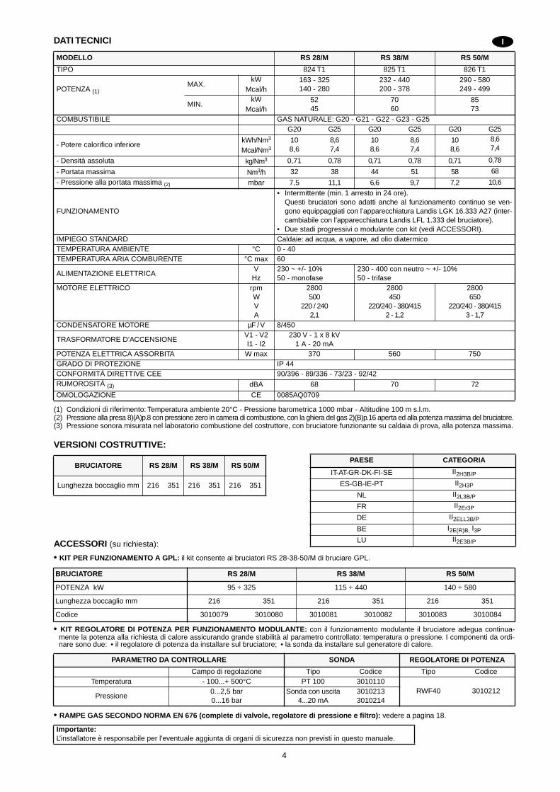
(1) Condizioni di riferimento: Temperatura ambiente 20°C - Pressione barometrica 1000 mbar - Altitudine 100 m s.l.m.(2) Pressione alla presa 8)(A)p.8 con pressione zero in camera di combustione, con la ghiera del gas 2)(B)p.16 aperta ed alla potenza massima del bruciatore.(3) Pressione sonora misurata nel laboratorio combustione del costruttore, con bruciatore funzionante su caldaia di prova, alla potenza massima.
VERSIONI COSTRUTTIVE:
ACCESSORI
(su richiesta):
•
KIT PER FUNZIONAMENTO A GPL:
il kit consente ai bruciatori RS 28-38-50/M di bruciare GPL.
•
KIT REGOLATORE DI POTENZA PER FUNZIONAMENTO MODULANTE:
con il funzionamento modulante il bruciatore adegua continua-mente la potenza alla richiesta di calore assicurando grande stabilità al parametro controllato: temperatura o pressione. I componenti da ordi-nare sono due: • il regolatore di potenza da installare sul bruciatore; • la sonda da installare sul generatore di calore.
•
RAMPE GAS SECONDO NORMA EN 676 (complete di valvole, regolatore di pressione e filtro):
vedere a pagina 18.
MODELLO RS 28/M RS 38/M RS 50/M
TIPO 824 T1 825 T1 826 T1
POTENZA
(1)
MAX.kW 163 - 325
140 - 280232 - 440200 - 378
290 - 580249 - 499Mcal/h
MIN.kW 52
457060
8573Mcal/h
COMBUSTIBILE GAS NATURALE: G20 - G21 - G22 - G23 - G25G20 G25 G20 G25 G20 G25
- Potere calorifico inferiorekWh/Nm
3
Mcal/Nm
3
108,6
8,67,4
108,6
8,67,4
108,6
8,67,4
- Densità assoluta kg/Nm
3
0,71 0,78 0,71 0,78 0,71 0,78
- Portata massima Nm
3
/h 32 38 44 51 58 68
- Pressione alla portata massima
(2)
mbar 7,5 11,1 6,6 9,7 7,2 10,6
FUNZIONAMENTO
• Intermittente (min. 1 arresto in 24 ore).Questi bruciatori sono adatti anche al funzionamento continuo se ven-gono equippaggiati con l’apparecchiatura Landis LGK 16.333 A27 (inter-cambiabile con l’apparecchiatura Landis LFL 1.333 del bruciatore).
• Due stadi progressivi o modulante con kit (vedi ACCESSORI).IMPIEGO STANDARD Caldaie: ad acqua, a vapore, ad olio diatermicoTEMPERATURA AMBIENTE °C 0 - 40TEMPERATURA ARIA COMBURENTE °C max 60
ALIMENTAZIONE ELETTRICAV
Hz230 ~ +/- 10%50 - monofase
230 - 400 con neutro ~ +/- 10%50 - trifase
MOTORE ELETTRICO rpmWVA
2800500
220 / 2402,1
2800450
220/240 - 380/4152 - 1,2
2800650
220/240 - 380/4153 - 1,7
CONDENSATORE MOTORE µF / V 8/450
TRASFORMATORE D’ACCENSIONEV1 - V2I1 - I2
230 V - 1 x 8 kV1 A - 20 mA
POTENZA ELETTRICA ASSORBITA W max 370 560 750GRADO DI PROTEZIONE IP 44CONFORMITÀ DIRETTIVE CEE 90/396 - 89/336 - 73/23 - 92/42RUMOROSITÀ
(3)
dBA 68 70 72
OMOLOGAZIONE CE 0085AQ0709
BRUCIATORE RS 28/M RS 38/M RS 50/M
Lunghezza boccaglio mm 216 351 216 351 216 351
BRUCIATORE RS 28/M RS 38/M RS 50/M
POTENZA kW 95 ÷ 325 115 ÷ 440 140 ÷ 580
Lunghezza boccaglio mm 216 351 216 351 216 351
Codice 3010079 3010080 3010081 3010082 3010083 3010084
PARAMETRO DA CONTROLLARE SONDA REGOLATORE DI POTENZA
Campo di regolazione Tipo Codice Tipo CodiceTemperatura - 100...+ 500°C PT 100 3010110
RWF40 3010212Pressione
0...2,5 bar0...16 bar
Sonda con uscita4...20 mA
30102133010214
Importante:
L’installatore è responsabile per l’eventuale aggiunta di organi di sicurezza non previsti in questo manuale.
I
PAESE CATEGORIA
IT-AT-GR-DK-FI-SE II
2H3B/P
ES-GB-IE-PT II
2H3P
NL II
2L3B/P
FR II
2Er3P
DE II
2ELL3B/P
BE I
2E(R)B,
I
3P
LU II
2E3B/P

5
TECHNISCHE ANGABEN
(1) Bezugsbedingungen: Raumtemperatur 20°C - Barometrischer Druck 1000 mbar - Höhe 100 m ü.d.M.(2) Druck am Anschluß 8)(A)S.8 bei druckloser Brennkammer, geöffneter Gasscheibe 2)(B)S.16 und bei Höchstleistung des Brenners(3) Schalldruck, im Brennprüflabor des Herstellers mit Brenner auf Prüfkessel bei Höchstleistung.
BAUVARIANTEN:
ZUBEHÖRTEILE
(auf Wunsch):
•
KIT FÜR FLÜSSIGGAS-BETRIEB:
Der Kit erlaubt den Brennern RS 28-38-50/M Flüssiggas zu brennen.
•
KIT FÜR DIE LEISTUNGSREGELUNG BEI MODULIERENDEM BETRIEB:
Bei modulierendem Betrieb passt der Brenner die Leistung stufen-los dem Wärmebedarf an und stellt konstante Temperatur- oder Druckwerte sicher. Folgende Zubehörteile müssen bestellt werden: • der Leistungsregler (an den Brenner einzubauen); • der Fühler (an den Wärmeerzeuger einzubauen).
•
GASARMATUREN GEMÄß NORM EN 676 (mit Ventilen, Druckregler und Filter):
siehe Seite 19.
MODELL RS 28/M RS 38/M RS 50/M
TYP 824 T1 825 T1 826 T1
LEISTUNG
(1)
MAX.kW 163 - 325
140 - 280232 - 440200 - 378
290 - 580249 - 499Mcal/h
MIN. kW 52
457060
8573Mcal/h
BRENNSTOFF ERDGAS: G20 - G21 - G22 - G23 - G25G20 G25 G20 G25 G20 G25
- Heizwert HukWh/Nm
3
Mcal/Nm
3
108,6
8,67,4
108,6
8,67,4
108,6
8,67,4
- Reindichte kg/Nm
3
0,71 0,78 0,71 0,78 0,71 0,78
- Höchstdurchsatz Nm
3
/h 23 38 44 51 58 68
- Druck bei Höchstleistung
(2)
mbar 7,5 11,1 6,6 9,7 7,2 10,6
BETRIEB
• Intermittierend (min. 1 Abschaltung in 24 Std).Wenn dieser Brenner mit dem Gasfeuerungsautomaten Landis & GyrLGK 16.333 A27 ausgestattet ist, ist er auch für den Dauerbetrieb geei-gnet. Die elektrische Verdrahtung des Brenners bleibt unverändert.
• Gleitend zweistufig (modulierend mit Kit).STANDARDEINSATZ Heizkessel: mit Wasser, Dampf, diathermischem ÖlRAUMTEMPERATUR °C 0 - 40TEMPERATUR VERBRENNUNGSLUFT °C max 60
ELEKTRISCHE SPANNUNGV
Hz230 ~ +/- 10%50 - einphasig
230 - 400 mit Nulleiter ~ +/- 10%50 - dreiphasig
ELEKTROMOTOR rpmWVA
280025
220 - 2402,1
2800450
220/240 - 380/4152 - 1,2
2800650
220/240 - 380/4153 - 1,7
MOTORKONDENSATOR µF / V 8/450
ZÜNDTRANSFORMATORV1 - V2I1 - I2
230 V - 1 x 8 kV1 A - 20 mA
AUFGENOMMENE STROMLEISTUNG W max 370 560 750SCHUTZART IP 44CE-NORMGERECHT 90/396 - 89/336 - 73/23 - 92/42SHALLDRUCKPEGEL
(3)
dBA 68 70 72
ZULASSUNGEN CE 0085AQ0709
BRENNER RS 28/M RS 38/M RS 50/M
Flammrohr Länge mm 216 351 216 351 216 351
BRENNER RS 28/M RS 38/M RS 50/M
LEISTUNG kW 95 ÷ 325 115 ÷ 440 140 ÷ 580
Flammrohr Länge mm 216 351 216 351 216 351
Code 3010079 3010080 3010081 3010082 3010083 3010084
WERT ZU ÜBERWACHEN FÜHLER LEISTUNGSREGLER
Regelbereich Typ Code Typ CodeTemperatur - 100...+ 500°C PT 100 3010110
RWF40 3010212Druck
0...2,5 bar0...16 bar
Fühler mit Ausgang4...20 mA
30102133010214
Wichtiger Hinweis:
Der Installateur haftet für den eventuellen Zusatz von Sicherheitsteilen, die nicht in dieser Betriebsanleitung vorgesehen sind.
D
LAND KATEGORIE
IT-AT-GR-DK-FI-SE II
2H3B/P
ES-GB-IE-PT II
2H3P
NL II
2L3B/P
FR II
2Er3P
DE II
2ELL3B/P
BE I
2E(R)B,
I
3P
LU II
2E3B/P

6
TECHNICAL DATA
(1) Reference conditions: Ambient temperature 20°C - Barometric pressure 1000 mbar - Altitude 100 m a.s.l.(2) Pressure at test point 8)(A)p.8, with zero pressure in the combustion chambre, with open gas ring 2)(B)p.16 an maximum burner output(2) Sound pressure measured in manufacturers combustion laboratory, with burner operating on test boiler and at maximum rated output.
VARIANTS:
ACCESSORIES
(optional):
•
KIT FOR LPG OPERATION:
The kit allows the RS 28-38-50/M burners to operate on LPG.
•
OUTPUT POWER REGULATOR KIT:
Under modulating operation, the burner automatically adapts to one of an infinite number of firing ratesbetween the low and high flame output position, thus ensuring stable operating conditions in terms of temperature or pressure. Two componentsshould be ordered: • Power regulator to install to the burner; • probe to install to the boiler.
•
GAS TRAIN ACCORDING TO REGULATION EN 676 (with valves, pressure governor and filter):
see page 19.
MODEL RS 28/M RS 38/M RS 50/M
TYPE 824 T1 825 T1 826 T1
OUTPUT
(1)
MAX.kW 163 - 325
140 - 280232 - 440200 - 378
290 - 580249 - 499Mcal/h
MIN.kW 52
457060
8573Mcal/h
FUEL NATURAL GAS: G20 - G21 - G22 - G23 - G25G20 G25 G20 G25 G20 G25
- Net calorific valuekWh/Nm
3
Mcal/Nm
3
108,6
8,67,4
108,6
8,67,4
108,6
8,67,4
- Absolute density kg/Nm
3
0,71 0,78 0,71 0,78 0,71 0,78
- Max. delivery Nm
3
/h 32 38 44 51 58 68
- Pressure at max. delivery
(2)
mbar 7,5 11,1 6,6 9,7 7,2 10,6
OPERATION
• On-Off (1 stop min each 24 hours).This burner is also fitted for the continuos operation, if it is equipped with the control box LANDIS type LGK 16.333 A27 (interchangeable with the burner control box Landis LFL 1.333).
• Progressive two-stage or modulating by kit (see ACCESSOIRES).STANDARD APPLICATIONS Boilers: water, steam, diathermic oilAMBIENT TEMPERATUR °C 0 - 40COMBUSTION AIR TEMPERATURE °C max 60
ELECTRICAL SUPPLYV
Hz230 ~ +/- 10%50 - single-phase
230 - 400 with neutral ~ +/- 10%50 - three-phase
ELECTRIC MOTOR rpmWVA
2800250
220 - 2402,1
2800450
220/240 - 380/4152 - 1,2
2800650
220/240 - 380/4153 - 1,7
MOTOR CAPACITOR µF / V 8/450
IGNITION TRANSFORMERV1 - V2I1 - I2
230 V - 1 x 8 kV1 A - 20 mA
ELECTRICAL POWER CONSUMPTION W max 370 560 750ELECTRICAL PROTECTION IP 44IN CONFORMITY WITH EEC DIRECTIVES 90/396 - 89/336 - 73/23 - 92/42NOISE LEVELS
(3)
dBA 68 70 72
APPROVAL CE 0085AQ0709
BURNER RS 28/M RS 38/M RS 50/M
Blast tube lenght mm 216 351 216 351 216 351
BURNER RS 28/M RS 38/M RS 50/M
OUTPUT kW 95 ÷ 325 115 ÷ 440 140 ÷ 580
Blast tube lenght mm 216 351 216 351 216 351
Code 3010079 3010080 3010081 3010082 3010083 3010084
PARAMETER TO BE CHECKED PROBE POWER REGULATOR
Range Type Code Type CodeTemperature - 100...+ 500°C PT 100 3010110
RWF40 3010212Pressure
0...2,5 bar0...16 bar
Output probe4...20 mA
30102133010214
Important:
The installer is responsible for the addition of any safety device not forseen in the present manual.
GB
COUNTRY CATEGORY
IT-AT-GR-DK-FI-SE II
2H3B/P
ES-GB-IE-PT II
2H3P
NL II
2L3B/P
FR II
2Er3P
DE II
2ELL3B/P
BE I
2E(R)B,
I
3P
LU II
2E3B/P

7
DONNEES TECHNIQUES
(1) Conditions de référence: Température ambiante 20°C - Pression barométrique 1000 mbar - Altitude 100 m au-dessus du niveau de la mer.(2) Pression à la prise 8)(A)p.8, avec une pression nulle dans la chambre de combustion, avec la bague du gaz 2)(B)p.16 ouverte et à la puis-
sance maximum du brûleur.(3) Pression acoustique mesurée dans le laboratoire combustion du constructeur, le brûleur fonctionnant sur une chaudière d’essai à la puissance maximum.
MODELES DISPONIBLES:
ACCESSORIES
(sur demande):
•
KIT POUR FONCTIONNEMENT AU GPL:
Le kit permet aux brûleurs RS 28-38-50/M de fonctionner au GPL.
•
KIT REGULATEUR DE PUISSANCE POUR FONCTIONNEMENT MODULANT: En fonctionnement modulant, le brûleur adapte continuelle-ment la puissance à la demande de chaleur assurant une grande stabilité au paramètre contrôlé: température ou pression. Il faut commander 2composants: • Le régulateur de puissance à installer sur le brûleur; • la sonde à installer sur le générateur de chaleur.
• RAMPES GAZ SELON LA NORME EN 676 (avec vannes, regulateur de pression et filtre): voir p. 19.
MODELE RS 28/M RS 38/M RS 50/M
TYPE 824 T1 825 T1 826 T1
PUISSANCE (1)
MAX.kW 163 - 325
140 - 280232 - 440200 - 378
290 - 580249 - 499Mcal/h
MIN.kW 52
457060
8573Mcal/h
COMBUSTIBLE GAZ NATUREL: G20 - G21 - G22 - G23 - G25G20 G25 G20 G25 G20 G25
- Pouvoir calorifique inférieurkWh/Nm3
Mcal/Nm3
108,6
8,67,4
108,6
8,67,4
108,6
8,67,4
- Densité absolue kg/Nm3 0,71 0,78 0,71 0,78 0,71 0,78
- Débit maximum Nm3/h 32 38 44 51 58 68
- Pression au débit max. (2) mbar 7,5 11,1 6,6 9,7 7,2 10,6
FONCTIONNEMENT
• Intermittent (1 arrêt min en 24 heures).Ce brûleurs est appropriés aussi pour le service permanent, s’il est équipés avec le boîtier LANDIS type LGK 16.333 A 27 (interchangeable avec le boîtier, LANDIS type LFL 1.333, du brûleur).
• Deux allure progressives ou modulant avec kit (voir ACCESSOIRES).EMPLOI STANDARD Chaudières à eau, à vapeur, à huile diathermiqueTEMPERATURE AMBIANTE °C 0 - 40TEMPERATURE AIR COMBURANT °C max 60
ALIMENTATION ELECTRIQUEV
Hz230 ~ +/- 10%50 - monophasée
230 - 400 avec neutre ~ +/- 10%50 - triphasée
MOTEUR ELECTRIQUE rpmWVA
2800250
220 - 2402,1
2800450
220/240 - 380/4152 - 1,2
2800650
220/240 - 380/4153 - 1,7
CONDENSATEUR MOTEUR µF / V 8/450
TRANSFORMATEUR D’ALLUMAGEV1 - V2I1 - I2
230 V - 1 x 8 kV1 A - 20 mA
PUISSANCE ELECTRIQUE ABSORBEE W max 370 560 750DEGRE DE PROTECTION IP 44CONFORMÉMENT AUX DIRECTIVES CEE 90/396 - 89/336 - 73/23 - 92/42NIVEAU DE BRUIT (3) dBA 68 70 72
HOMOLOGATION CE 0085AQ0709
BRULEUR RS 28/M RS 38/M RS 50/M
Longuer buse mm 216 351 216 351 216 351
BRULEUR RS 28/M RS 38/M RS 50/M
PUISSANCE kW 95 ÷ 325 115 ÷ 440 140 ÷ 580
Longuer buse mm 216 351 216 351 216 351
Code 3010079 3010080 3010081 3010082 3010083 3010084
PARAMETRE A CONTROLER SONDE REGULATEUR DE PUISSANCE
Plage de régulation Type Code Type CodeTempérature - 100...+500°C PT 100 3010110
RWF40 3010212Pression
0...2,5 bar0...16 bar
Sonde avec sortie4...20 mA
30102133010214
Attention:Si l’installateur ajoute des organes de sécurité non prévus dans ce manuel, il en assume la responsabilité.
F
PAYS CATEGORIE
IT-AT-GR-DK-FI-SE II2H3B/P
ES-GB-IE-PT II2H3P
NL II2L3B/P
FR II2Er3P
DE II2ELL3B/P
BE I2E(R)B, I3P
LU II2E3B/P

8
DESCRIZIONE BRUCIATORE (A)1 Testa di combustione2 Elettrodo d’accensione3 Vite per regolazione testa di combustione4 Pressostato gas di massima5 Pressostato aria (tipo differenziale)6 Sonda per il controllo presenza fiamma 7 Presa di pressione aria 8 Presa di pressione gas e vite fissa testa9 Vite per il fissaggio ventilatore al manicotto 10 Guide per apertura bruciatore ed ispezione
alla testa di combustione 11 Servomotore, comanda la farfalla del gas e,
tramite una camma a profilo variabile, la ser-randa dell’aria.Durante la sosta del bruciatore la serrandadell’aria è completamente chiusa per ridurreal minimo le dispersioni termiche della cal-daia dovute al tiraggio del camino cherichiama l’aria dalla bocca di aspirazione delventilatore.
12 Piastrina predisposta per ottenere 4 fori, utilial passaggio dei cavi elettrici
13 Ingresso aria nel ventilatore14 Condotto arrivo gas15 Valvola farfalla gas16 Flangia per il fissaggio alla caldaia 17 Disco di stabilità fiamma18 Visore fiamma 19 Un interruttore per:
funzionamento automatico-manuale-spentoUn pulsante per:aumento - diminuzione potenza
20 Contattore motore e relè termico con pul-sante di sblocco (RS 38-50/M)
21 Condensatore motore (RS 28/M)22 Apparecchiatura elettrica con avvisatore
luminoso di blocco e pulsante di sblocco23 Morsettiera per il collegamento elettrico 24 Serranda aria 25 Tubetto che collega l’aspirazione del ventila-
tore al pressostato aria26 Staffa per l’applicazione del regolatore di
potenza RWF4027 Spina-presa sul cavo della sonda di ionizza-
zione
Vi sono due possibilità di blocco del bruciatore:• BLOCCO APPARECCHIATURA:
l’accensione del pulsante dell’apparecchiatura22)(A) avverte che il bruciatore è in blocco.Per sbloccare premere il pulsante.
• BLOCCO MOTORE (RS 38-50/M):alimentazione elettrica a due fasi, per sbloc-care premere il pulsante del relè termico20)(A).
IMBALLO - PESO (B) - misure indicative• I bruciatori vengono spediti in imballi di car-
tone con dimensioni di ingombro secondotab. (B).
• Il peso del bruciatore completo di imballo èindicato nella tab. (B).
INGOMBRO (C) - misure indicativeL'ingombro del bruciatore è riportato in fig.(C).Tener presente che per ispezionare la testa dicombustione il bruciatore deve essere arretratoe ruotato verso l’alto.L'ingombro del bruciatore aperto, senza cofano,è indicato dalla quota H.
CORREDO1 - Flangia per rampa gas1 - Guarnizione per flangia4 - Viti per fissare la flangia M 8 x 251 - Schermo termico4 - Viti per fissare la flangia del bruciatore alla
caldaia: M 8 x 255 - Passacavi per collegamento elettrico
(RS 28/M)6 - Passacavi per collegamento elettrico
(RS 38-50/M)1 - Istruzione1 - Catalogo ricambi
(A)
(B)
mm A (1) B C kg
RS 28/M 872-1007 550 540 38
RS 38/M 872-1007 550 540 40
RS 50/M 872-1007 550 540 41
(1) Boccaglio: corto-lungo / Flammenrohr: kurz-lang / Blast tube: short-long / Buse: courte-longue
mm A B C D (1) E F G H I L M
RS 28/M 476 474 580 216-351 140 352 164 810 108 168 1”1/2
RS 38/M 476 474 580 216-351 140 352 164 810 108 168 1”1/2
RS 50/M 476 474 580 216-351 152 352 164 810 108 168 1”1/2
(C)
D776
D777
D778
D88
D495

9
BRENNERBESCHREIBUNG (A)1 Flammkopf2 Zündelektrode3 Einstellschraube des Flammkopfes4 Gas-Höchstdruckwächter5 Luftdruckwächter (Differentialtyp) 6 Flammenfühler7 Luftdruckentnahmestelle8 Gasdruckentnahmestelle und Befestigungs-
schraube des Flammkopfes 9 Befestigungsschraube des Gebläses an der
Gasanschluß-Muffe10 Gleitschienen zur Öffnung des Brenners und
für die Kontrolle des Flammkopfes11 Stellantrieb zur Steuerung der Gasdrossel
und, über einen Nocken mit variablem Profil,der Luftklappe.Bei Brennerstillstand ist die Luftklappe voll-ständig geschlossen, um die Wärmeverlustedes Kessels durch den Kaminzug mit Luft-nachführung von der Saugöffnung desGebläses zu vermindern.
12 Platte mit 4 Vorbohrungen zum Durchfüh-rung der Stromkabel
13 Lufteinlaß zum Gebläse14 Gaszuleitung, Winkelflansch15 Gasdrossel16 Befestigungsflansch am Kessel17 Stauscheibe18 Sichtfenster19 Ein Schalter für:
Automatischer Betrieb-Manueller Betrieb-AusEin Schalter für:Leistungserhöhung - Leistungabminderung
20 Motorschütz und Überstromauslöser mit Ent-riegelungsschalter (RS 38-50/M)
21 Motorkondensator (RS 28/M)22 Steuergerät mit Kontrollampe für Störab-
schaltung und Entriegelungsschalter 23 Anschlußklemmenbrett24 Luftklappe25 Rohr, das Ansaugöffnung des Gebläses mit
Luftdruckwächter verbindet26 Tragbügel zum Einbau des Leistungsreglers
RWF4027 Steckanschluß am Kabel der Ionisations-
sonde
Die Störabschaltungen des Brenners könnenzweierlei Art sein:• STÖRABSCHALTUNG DES GERÄTES:
das Aufleuchten des Druckknopfes des Gerä-tes, 22)(A) weist auf eine Störabschaltungdes Brenners hin.Zur Entriegelung den Druckknopf drücken.
• STÖRABSCHALTUNG DES MOTOR (RS 38-50/M): zweiphasen-Stromversongung, Entriegelungdurch Drücken auf den Druckknopf des Über-stromauslösers, 20)(A).
VERPACKUNG - GEWICHT (B) - Richtwerte• Der Brenner werden in Kartonverpackungen
geliefert, Abmessungen siehe Tab. (B).• Das Gesamtgewicht des Brenners einschließ-
lich Verpackung wird aus Tab. (B) ersichtlich.
ABMESSUNGEN (C) - RichtwerteDie Brennerabmessungen sind in der Abb. (C)angeführt.Zur Inspektion des Flammkopfes muß der Bren-ner zurückgezogen und nach oben geschwenktwerden. Die Abmessungen des ausgeschwenk-ten Brenners, ohne Verkleidung, sind unter Haufgeführt.
AUSSTATTUNG1 - Flansch für Gasarmaturen1 - Dichtung für Flansch4 - Schrauben für die Befestigung des M 8 x 25
Flansches1 - Wärmeschild4 - Schrauben für die Befestigung des Bren-
nerflanschs am Kessel: M 8 x 255 - Kabeldurchgänge für Elektroanschluß
(RS 28/M)6 - Kabeldurchgänge für Elektroanschluß
(RS 38-50/M)1 - Anleitung1 - Ersatzteile Katalog
BURNER DESCRIPTION (A)1 Combustion head2 Ignition electrode3 Screw for combustion head adjustment4 Max. gas pressure switch5 Minimum air pressure switch
(differential operating type)6 Flame sensor probe7 Air pressure test point 8 Gas pressure test point and head fixing
screw 9 Screws securing fan to sleeve10 Slide bars for opening the burner and
inspecting the combustion head 11 Servomotor controlling the gas butterfly valve
and the air gate valve (by means of a varia-ble profile cam mechanism).When the burner is stopped the air gatevalve will be completely closed to reduceheat loss due to the flue draught, whichtends to draws air from the fan air inlet.
12 Plate with 4 hole knock-outs for electricalcable routling
13 Air inlet to fan14 Gas input pipework15 Gas butterfly valve16 Boiler mounting flange 17 Flame stability disck18 Flame inspection window19 Power switch for different operations:
automatic - manual - offButton for:power increase - power reduction
20 Motor contactor and thermal cut-out withreset button (RS 38-50/M)
21 Motor capacitor (RS 28/M)22 Control box with lock-out pilot light and lock-
out reset button23 Terminal strip for electrical connection 24 Air gate valve 25 Pipe connection the fan air inlet to the air
pressure switch26 Bracket for mounting the power regulator
RWF4027 Plug-socket on ionisation proble cable
Two types of burner failure may occur:• CONTROL BOX LOCK-OUT:
if the control box 22)(A) pushbutton lights up,it indicates that the burner is in lock-out.To reset, press the pushbutton.
• MOTOR TRIP (RS 38-50/M): two-phase electricity supply; release bypressing the pushbutton on thermal cutout20)(A).
PACKAGING - WEIGHT (B) - Approximatemeasurements• The burners are shipped in cardboard boxes
with the maximum dimensions shown in tab.(B).
• The weight of the burner complete with pack-aging is indicated in tab. (B).
MAX. DIMENSIONS (C) - Approximate meas-urementsThe maximum dimensions of the burner aregiven in (C).Note that if you need to examine the combustionhead, the burner must be pulled backward onthe slide bars and turned upward.The maximum dimension of the burner, withoutthe cover, when open is give by measurementH.
STANDARD EQUIPMENT1 - Gas train flange1 - Flange gasket4 - Flange fixing screws M 8 x 251 - Thermal insulation screen4 - Screws to secure the burner flange to the
boiler: M 8 x 255 - Fairleads for electrical connections (RS 28/M)5 - Fairleads for electrical connections
(RS 38-50/M)1 - Instruction booklet1 - Spare parts list
DESCRIPTION BRULEUR (A)1 Tête de combustion2 Electrode d'allumage3 Vis pour réglage tête de combustion4 Pressostat gaz seuil maximum5 Pressostat air seul minimum
(type différentiel)6 Sonde de contrôle présence flamme7 Prise de pression air8 Prise de pression gaz et vis de fixation tête9 Vis de fixation ventilateur au manchon10 Guides pour ouverture brûleur et inspection
de la tête de combustion 11 Servomoteur de commande de la vanne
papillon du gaz et, par came à profil variable,du volet d'air. Lors de l'arrêt du brûleur ce volet d'air esttotalement fermé pour réduire au minimumles dispersions de chaleur de la chaudièredues au tirage de la cheminée qui aspire l'airpar la bouche d'aspiration du ventilateur.
12 Plaquette prévue avec 4 trous passe-câbles13 Entrée d’air dans le ventilateur14 Canalisation d’arrive du gaz15 Vanne papillon gaz16 Bride de fixation à la chaudière17 Disque de stabilité de la flamme18 Viseur flamme19 Un interrupteur pour le fonctionnement:
automatique - manuel - éteintUn bouton pour:augmentation - diminution de puissance
20 Contacteur moteur et relais thermique avecbouton de déblocage (RS 38-50/M)
21 Condensateur moteur (RS 28/M)22 Coffret de sécurité avec signal lumineux de
blocage et bouton de déblocage23 Bornier pour branchement électrique24 Volet d’air25 Tuyau qui relie l’aspiration du ventilateur au
pressostat de l’air26 Support pour l’application du régulateur de
puissance RWF4027 Fiche prise sur câble sonde d’ionisation
Il existe deux types de blocage du brûleur:• BLOCAGE COFFRET:
l'allumage du bouton du coffret de sécurité22)(A) signale que le brûleur s'est bloqué.Pour le débloquer appuyer sur le bouton.
• BLOCAGE MOTEUR (RS 38-50/M):alimentation électrique à deux phases; pourle débloquer appuyer sur le bouton-poussoirdu relais thermique 20)(A).
EMBALLAGE - POIDS (B) - Mesures indicatives• Le brûleur sont expédiés dans des emballa-
ges en carton dont les dimensions d’encom-brement sont indiquées dans le tab. (B).
• Le poids du brûleur avec son emballage estindiqué dans le tab. (B).
ENCOMBREMENT (C) - Mesures indicativesL'encombrement du brûleur est indiqué dans letab. (C).Attention: pour inspecter la tête de combustion,le brûleur doit être reculé et tourné vers le haut. L'encombrement du brûleur ouvert, sans carter,est indiqué par la cote H.
EQUIPEMENT STANDARD1 - Bride pour rampe gaz1 - Joint pour bride4 - Vis de fixation bride M 8 x 251 - Ecran thermique4 - Vis pour fixer la bride du brûleur à la chau-
dière: M 8 x 255 - Passe-câbles pour branchement électri-
que (RS 28/M)6 - Passe-câbles pour branchement électri-
que (RS 38-50/M)1 - Instructions1 - Catalogue pièces détachées

10
CAMPI DI LAVORO (A)La potenza del bruciatore varia in funziona-mento tra:
• una POTENZA MASSIMA , scelta entro l’ area A,• e una POTENZA MINIMA , che non deve
essere inferiore al limite minimo del dia-gramma:
RS 28/M = 52 kWRS 38/M = 70 kWRS 50/M = 85 kW
Attenzione Il CAMPO DI LAVORO è stato ricavato alla tem-peratura ambiente di 20 °C, alla pressione baro-metrica di 1000 mbar (circa 100 m s.l.m.) e conla testa di combustione regolata come indicato apagina 16.
CALDAIA DI PROVA (B)I campi di lavoro sono stati ricavati in specialicaldaie di prova, secondo la norma EN 676.Riportiamo in (B) diametro e lunghezza dellacamera di combustione di prova.Esempio Potenza 350 Mcal/h:diametro 50 cm - lunghezza 1,5 m.
CALDAIE COMMERCIALI L’abbinamento bruciatore-caldaia non pone pro-blemi se la caldaia è omologata CE e le dimen-sioni della sua camera di combustione sonovicine a quelle indicate dal diagramma (B).Se, invece, il bruciatore deve essere applicatoad una caldaia commerciale non omologata CEe/o con dimensioni della camera di combustionenettamente più piccole di quelle indicate dal dia-gramma (B), consultare i costruttori.
(B)
CA
M. C
OM
B. /
FE
UE
RR
AU
M
mC
OM
B. C
HA
MB
ER
/ C
HA
MB
. CO
MB
.C
AM
. CO
MB
. / F
EU
ER
RA
UM
m
bar
CO
MB
. CH
AM
BE
R /
CH
AM
B. C
OM
B.
CA
M. C
OM
B. /
FE
UE
RR
AU
M
mba
rC
OM
B. C
HA
MB
ER
/ C
HA
MB
. CO
MB
.C
AM
. CO
MB
. / F
EU
ER
RA
UM
m
bar
CO
MB
. CH
AM
BE
R /
CH
AM
B. C
OM
B.
(A) D1061
D497

11
REGELBEREICHE (A)Wahrend des Betriebs schwankt die Brennerlei-stung zwischen:
• einer HÖCHSTLEISTUNG, innerhalb desFeldes A gewählt,
• und einer MINDESTLEISTUNG, die nichtniedriger sein darf als die Mindestgrenze desDiagramms.
RS 28/M = 52 kWRS 38/M = 70 kWRS 50/M = 85 kW
AchtungDer REGELBEREICH wurde bei einer Raum-temperatur von 20 °C, einem barometrischenDruck von 1000 mbar (ungefähr 100 m ü.d.M.)und bei wie auf Seite 17 eingestelltem Flamm-kopf gemessen.
PRÜFKESSEL (B)Die Regelbereiche wurden an speziellen Prüf-kesseln entsprechend Norm EN 676 ermittelt.In (B) sind Durchmesser und Länge der Prüf-brennkammer angegeben.BeispielLeistung 350 Mcal/h:Durchmesser = 50 cm - Länge = 1,5 m.
HANDELSÜBLICHE KESSEL Die Brenner-Kessel Kombination gibt keine Pro-bleme, falls der Kessel "CE" - typgeprüft ist unddie Abmessungen seiner Brennkammer sichden im Diagramm (B) angegebenen nähern.Falls der Brenner dagegen an einem handelsüb-lichen Kessel angebracht werden muß, der nicht"CE"-typgeprüft ist und/oder mit Abmessungender Brennkammer, die entschieden kleiner alsjene in Diagramm (B) angegebenen sind, sollteder Hersteller zu Rate gezogen werden.
FIRING RATES (A)During operation, burner output varies between:
• a MAXIMUM OUTPUT, selected within area A,• and a MINIMUM OUTPUT, which must not be
lower than the minimum limit in the diagram.
RS 28/M = 52 kWRS 38/M = 70 kWRS 50/M = 85 kW
Important The FIRING RATE area values have beenobtained considering an ambient temperature of20 °C, and an atmospheric pressure of 1000mbar (approx. 100 m above sea level) and withthe combustion head adjusted as shown onpage 17.
TEST BOILER (B)The firing rates were set in relation to specialtest boilers, according to EN 676 regulations.Figure (B) indicates the diameter and length ofthe test combustion chamber.ExampleOutput 350 Mcal/h:diameter = 50 cm - length = 1,5.
COMMERCIAL BOILERS The burner/boiler combination does not poseany problems if the boiler is CE type-approvedand its combustion chamber dimensions aresimilar to those indicated in diagram (B).If the burner must be combined with a commer-cial boiler that has not been Ce type-approvedand/or its combustion chamber dimensions areclearly smaller than those indicated in diagram(B), consult the manufacturer.
PLAGES DE PUISSANCE (A)La puissance du brûleur en fonctionnementvarie entre:
• une PUISSANCE MAXIMUM , choisie dans laplage A,
• et une PUISSANCE MINIMUM, qui ne doitpas être inférieure à la limite minimum du dia-gramme.
RS 28/M = 52 kWRS 38/M = 70 kWRS 50/M = 85 kW
AttentionLa PLAGE DE PUISSANCE a été calculée àune température ambiante de 20 °C, à unepression barométrique de 1000 mbar (environ100 m au-dessus du niveau de la mer) et avecla tête de combustion réglée comme indique lapage 17.
CHAUDIERE D’ESSAI (B)Les plages de puissance ont été établies surdes chaiuières d’essai spéciales, selon la normeEN 676. Nous reportons fig.(B) le diamètre et la longueurde la chambre de combustion d’essai.ExempePuissance 350 Mcal/h:diamètre 50 cm - longueur 1,5 m.
CHAUDIERES COMMERCIALES L’accouplement brûleur-chaudière ne poseaucun problème si la chaudière est homologuéeCE et si les dimensions de sa chambre de com-bustion sont proches de celles indiquées dansle diagramme (B).Par contre, si le brûleur doit être accouplé à unechaudière commerciale non homologuée CE,et/ou avec des dimensions de chambre de com-bustion plus petites que celles indiquées dans lediagramme (B), consulter le constructeur.

12
PRESSIONE GASLe tabelle a lato indicano le perdite di caricominime lungo la linea di alimentazione del gas infunzione della potenza massima del bruciatore.
Colonna 1Perdita di carico testa di combustione.Pressione del gas alla presa 1)(B), con:• Camera di combustione a 0 mbar• Bruciatore funzionante alla potenza massima• A = Ghiera del gas 2)(B)p.16 regolata come
diagramma (C)p.16.• B = Ghiera del gas 2)(B) regolata a zero.
Colonna 2Perdita di carico farfalla gas 2)(B) con aperturamassima: 90°.
Colonna 3Perdita di carico rampa 3)(B) comprendente:valvola di regolazione VR, valvola di sicurezzaVS (entrambe con apertura massima), regola-tore di pressione R, filtro F.
I valori riportati nelle tabelle si riferiscono a:gas naturale G 20 PCI 10 kWh/Nm3 (8,6 Mcal/Nm3)Con:gas naturale G 25 PCI 8,6 kWh/Nm3 (7,4 Mcal/Nm3)moltiplicare i valori delle tabelle per 1,3.
Per conoscere la potenza approssimativa allaquale sta funzionando il bruciatore al MAX:- sottrarre dalla pressione del gas alla presa
1)(B) la pressione in camera di combustione.- Trovare nella tabella relativa al bruciatore
desiderato, colonna 1A o B, il valore di pres-sione più vicino al risultato della sottrazione.
- Leggere sulla sinistra la potenza corrispon-dente.
Esempio - RS 28/M:• Funzionamento alla potenza MAX• Gas naturale G 20 PCI 10 kWh/Nm3
• Ghiera del gas 2)(B)p.16 regolata come dia-gramma (C)p.16
• Pressione del gas alla presa 1)(B) = 6 mbar• Pressione in camera combustione = 2 mbar
6 - 2 = 4 mbarAlla pressione 4 mbar, colonna 1A, corrispondenella tabella RS 28/M una potenza di 210 kW.Questo valore serve come prima approssima-zione; la portata effettiva va misurata al conta-tore.
Per conoscere invece la pressione del gasnecessaria alla presa 1)(B), fissata la potenzaMAX alla quale si desidera funzioni il bruciatore:- trovare nella tabella relativa al bruciatore con-
siderato il valore di potenza più vicino alvalore desiderato.
- Leggere sulla destra, colonna 1A o B, la pres-sione alla presa 1)(B).
- Sommare a questo valore la presunta pres-sione in camera di combustione.
Esempio - RS 28/M:• Potenza MAX desiderata: 210 kW• Gas naturale G 20 PCI 10 kWh/Nm3
• Ghiera del gas 2)(B)p.16 regolata come dia-gramma (C)p.16
• Pressione del gas alla potenza di 210 kW,dalla tabella RS 28/M, colonna 1A = 4 mbar
• Pressione in camera combustione = 2 mbar4 + 2 = 6 mbar
pressione necessaria alla presa 1)(B).
(A)
(B)
RS 28/M ∆p (mbar)
RS 38/M ∆p (mbar)
RS 50/M ∆p (mbar)
kW1
A - B2
3
Ø 3/43970076
Ø 13970077
Ø 1 1/43970144
Ø 1 1/23970145
Ø 1 1/23970180
165 2,5 - 2,5 0,1 11,1 5,3 3,2 2,1 1,8
185 3,1 - 3,3 0,1 13,4 6,4 3,8 2,5 2,0
210 4,0 - 4,3 0,1 16,5 7,9 4,7 3,1 2,5
235 4,7 - 5,2 0,2 19,9 9,5 5,6 3,8 3,2
260 5,5 - 5,8 0,2 23,6 11,2 6,6 4,5 3,7
285 6,3 - 6,8 0,3 27,5 13,1 7,6 5,3 4,4
310 7,0 - 7,8 0,3 31,6 15,0 8,7 6,2 4,7
325 7,5 - 9,1 0,3 34,2 16,2 9,4 6,7 4,9
kW1
A - B2
3
Ø 13970077
Ø 1 1/43970144
Ø 1 1/23970145
Ø 1 1/23970180
Ø 239701463970160
Ø 239701813970182
230 2,6 - 2,6 0,2 9,2 5,4 3,6 3,0 1,4 1,8
260 3,1 - 3,5 0,2 11,2 6,6 4,5 3,7 1,7 2,2
290 3,7 - 4,5 0,3 13,4 7,9 5,5 4,4 2,1 2,7
320 4,3 - 5,8 0,3 15,8 9,2 6,5 4,8 2,5 3,3
350 4,8 - 6,9 0,4 18,3 10,6 7,6 5,9 3,0 3,5
380 5,4 - 7,9 0,4 20,9 12,1 8,8 6,6 3,5 4,0
410 6,0 - 9,0 0,5 23,7 13,7 10,1 7,0 4,0 4,4
440 6,6 - 10,7 0,6 26,6 15,3 11,4 8,1 4,5 5,0
kW1
A - B2
3
Ø 13970077
Ø 1 1/43970144
Ø 1 1/23970145
Ø 1 1/23970180
Ø 239701463970160
Ø 239701813970182
290 2,2 - 2,2 0,3 13,4 7,9 5,5 4,4 2,1 2,7
330 2,9 - 3,3 0,4 16,6 9,7 6,9 5,0 2,7 3,4
370 3,6 - 4,1 0,5 20,0 11,6 8,4 6,1 3,3 3,9
410 4,3 - 5,1 0,6 23,7 13,7 10,1 7,0 4,0 4,4
450 5,0 - 6,0 0,7 27,6 15,9 11,9 8,3 4,7 5,1
490 5,6 - 7,0 0,9 31,7 18,2 13,7 9,7 5,5 5,9
530 6,3 - 8,0 1,0 36,1 20,6 15,7 10,5 6,3 6,6
580 7,2 - 9,6 1,2 41,8 23,9 18,5 12,0 7,4 7,8
D934

13
GASDRUCKIn den nebenstehenden Tabellen werden dieMindestströmungsverluste entlang der Gaszu-leitung in Abhängigkeit der Höchstleistung desBrenners angezeigt.
Spalte 1Strömungsverlust Flammkopf.Gasdruck am Anschluß 1)(B) gemessen, bei:• Brennkammer auf 0 mbar• Brennerbetrieb auf Höchstleistung• A = Gemäß Diagramm (C)S.16 eingestellter
Gasscheibe 2)(B)S.16• B = Gasscheibe 2)(B) auf Null eingestellt.
Spalte 2Strömungsverlust Gasdrossel 2)(B) bei maxima-ler Öffnung: 90°.
Spalte 3Strömungsverlust Armaturen 3)(B) bestehendaus: Regelventil VR, Sicherheitsventil VS (beidebei maximaler Öffnung), Druckregler R, Filter F.
Die Tabellenwerte beziehen sich auf:Erdgas G20 - Hu 10 kWh/Nm3 (8,6 Mcal/Nm3)Bei:Erdgas G25 - Hu 8,6 kWh/Nm3 (7,4 Mcal/Nm3)die Tabellenwerte mit 1,3 multiplizieren.
Zur Ermittlung der ungefähren Brennerleistungim Betrieb auf der Höchstleistung des Brenners:- vom Gasdruck an der Entnahmestelle 1)(B)
den Druck in der Brennkammer abziehen.- In der Tabelle des betreffenden Brenners,
unter Spalte 1A oder B, den der Subtraktionnächsten Wert ablesen.
- Die entsprechende Leistung links ablesen.
Beispiel - RS 28/M:• Betrieb auf Höchstleistung• Erdgas G20 -Hu 10 kWh/Nm3
• Gemäß Diagramm (C) S.16 eingestellte Gas-scheibe 2)(B)S.16
• Gasdruck an der Entnahmestelle 1)(B) = 6 mbar• Druck in der Brennkammer = 2 mbar
6 - 2 = 4 mbarDem Druck von 4 mbar, Spalte 1A, entspricht inder Tabelle RS 28/M eine Leistung von 210 kW.Dieser Wert dient als erste Näherung; der tat-sächliche Durchsatz wird am Zähler abgelesen.
Zur Ermittlung des für den an der Entnahme-stelle 1)(B) erforderlichen Gasdrucks, nachdemdie gewünschte Höchstleistung des Brennersfestgelegt wurde:- in der Tabelle des betreffenden Brenners die
dem gewünschten Wert nächste Leistungsan-gabe ablesen.
- Rechts, unter der Spalte 1A oder B, denDruck an der Entnahmestelle 1)(B) ablesen.
- Diesen Wert mit dem angenommenen Druckin der Brennkammer addieren.
Beispiel - RS 28/M:• Gewünschte Höchstleistung: 210 kW• Erdgas G20 - Hu 10 kWh/Nm3
• Gemäß Diagramm (C)S.16 eingestellte Gas-scheibe 2)(B)S.16
• Gasdruck bei 210 kW Leistung, aus TabelleRS 28/M, Spalte 1A = 4 mbar
• Druck in der Brennkammen = 2 mbar4 + 2 = 6 mbar
erforderlicher Druck an der Entnahmestelle1)(B).
GAS PRESSUREThe adjacent tables show minimum pressurelosses along the gas supply line depending onthe maximum burner output operation.
Column 1Pressure loss at combustion head.Gas pressure measured at test point 1)(B), with:• Combustion chamber at 0 mbar• Burner operating at maximum output• A = Gas ring 2)(B)p.16 adjusted as indicated
in diagram (C)p.16• B = Gas ring 2)(B) adjusted to zero.
Column 2Pressure loss at gas butterfly valve 2)(B) withmaximum opening: 90°.
Column 3Pressure loss of gas train 3)(B) includes: adjust-ment valve VR, safety valve VS (both fully open),pressure governor R, filter F.
The values shown in the various tables refer to:natural gas G 20 PCI 10 kWh/Nm3 (8,6 Mcal/Nm3)With:natural gas G 25 PCI 8,6 kWh/Nm3 (7,4 Mcal/Nm3)multiply tabulated values by 1,3.
Calculate the approximate maximum output ofthe burner thus:- subtract the combustion chamber pressure
from the gas pressure measured at test point1)(B).
- Find the nearest pressure value to your resultin column 1A or B of the table for the burner inquestion.
- Read off the corresponding output on the left.
Example - RS 28/M:• Maximum output operation• Natural gas G 20 PCI 10 kWh/Nm3
• Gas ring 2)(B)p.16 adjusted as indicated indiagram (C)p.16
• Gas pressure at test point 1)(B) = 6 mbar• Pressure in combustion chamber = 2 mbar
6 - 2 = 4 mbarA maximum output of 210 kW shown in TableRS 28/M corresponds to 4 mbar pressure, col-umn 1A.This value serves as a rough guide, the effectivedelivery must be measured at the gas meter.
To calculate the required gas pressure at testpoint 1)(B), set the maximim output requiredfrom the burner operation:- find the nearest output value in the table for
the burner in question.- Read off the pressure at test point 1)(B) on
the right in column 1A or B.- Add this value to the estimated pressure in
the combustion chamber.
Example - RS 28/M:• Required burner maximum output operation:
210 kW• Natural gas G 20 PCI 10 kWh/Nm3
• Gas ring 2)(B)p.16 adjusted as diagram(C)p.16
• Gas pressure at burner output of 210 kW, takenfrom table RS 28/M, column 1A = 4 mbar
• Pressure in combustion chamber = 2 mbar4 + 2 = 6 mbar
pressure required at test point 1)(B).
PRESSION DU GAZLes tableaux ci-contre indiquent les pertes decharge minimales sur la ligne d'alimentation engaz en fonction de la puissance maximum dubrûleur.
Colonne 1Perte de charge tête de combustion.Pression du gaz mesurée à la prise 1)(B), avec:• Chambre de combustion à 0 mbar• Brûleur fonctionnant à la puissance maximum• A = Bague du gaz 2)(B)p.16 réglée selon le
diagramme (C)p.16• B = Bague du gaz 2)(B) réglée à zéro.
Colonne 2Perte de charge vanne papillon gaz 2)(B) avecouverture maximum: 90°.
Colonne 3Perte de charge de la rampe gaz 3)(B) compre-nant: vanne de régulation VR, vanne de sûretéVS (ayant chacune une ouverture maximum),régulateur de pression R, filtre F.
Les valeurs reportées sur les tableaux se réfè-rent à:gaz naturel G 20 PCI 10 kWh/Nm3 (8,6 Mcal/Nm3)Avec:gaz naturel G 25 PCI 8,6 kWh/Nm3 (7,4 Mcal/Nm3)multiplier les valeurs des tableaux par 1,3.
Pour connaître la puissance maximum approxi-mative à laquelle le brûleur fonctionne:- soustraire la pression dans la chambre de
combustion de la pression du gaz à la prise1)(B).
- Repérer la valeur la plus proche du résultatobtenu sur le tableau relatif au brûleur consi-déré, colonne 1A ou B.
- Lire la puissance correspondante sur la gau-che.
Exemple - RS 28/M:• Fonctionnement à la puissance maximum• Gaz naturel G 20 PCI 10 kWh/Nm3
• Bague du gaz 2)(B)p.16 réglée selon le dia-gramme (C)p.16
• Pression du gaz à la prise 1)(B) = 6 mbar• Pression en chambre de combustion = 2 mbar
6 - 2 = 4 mbarSur le tableau RS 28/M à la pression de 4 mbar,colonne 1A, correspond une puissance de 210kW.Cette valeur sert de première approximation; ledébit effectif est mesuré sur le compteur.
Par contre, pour connaître la pression du gaznécessaire à la prise 1)(B), après avoir fixé lapuissance maximum de fonctionnement du brû-leur:- repérer la puissance la plus proche à la
valeur voulue dans le tableau relatif au brû-leur concerné.
- Lire la pression à la prise 1)(B) sur la droite,colonne 1A ou B.
- Ajouter à cette valeur la pression estiméedans la chambre de combustion.
Exemple - RS 100/M:• Puissance maximum désirée: 210 kW• Gaz naturel G 20 PCI 10 kWh/Nm3
• Bague du gaz 2)(B)p.16 réglée selon le dia-gramme (C)p.16
• Pression du gaz à la puissance de 210 kW, surle tableau RS 28/M, column 1A = 4 mbar
• Pression dans la chambre de comb.= 2 mbar4 + 2 = 6 mbar
pression nécessaire à la prise 1)(B).
14
INSTALLAZIONE
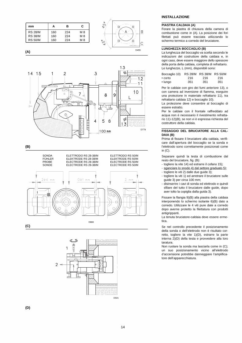
PIASTRA CALDAIA (A) Forare la piastra di chiusura della camera dicombustione come in (A). La posizione dei forifilettati può essere tracciata utilizzando loschermo termico a corredo del bruciatore.
LUNGHEZZA BOCCAGLIO (B) La lunghezza del boccaglio va scelta secondo leindicazioni del costruttore della caldaia e, inogni caso, deve essere maggiore dello spessoredella porta della caldaia, completa di refrattario.Le lunghezze, L (mm), disponibili sono:
Boccaglio 10) RS 28/M RS 38/M RS 50/M• corto 216 216 216• lungo 351 351 351
Per le caldaie con giro dei fumi anteriore 13), ocon camera ad inversione di fiamma, eseguireuna protezione in materiale refrattario 11), trarefrattario caldaia 12) e boccaglio 10).La protezione deve consentire al boccaglio diessere estratto.Per le caldaie con il frontale raffreddato adacqua non è necessario il rivestimento refratta-rio 11)-12)(B), se non vi è espressa richiesta delcostruttore della caldaia.
FISSAGGIO DEL BRUCIATORE ALLA CAL-DAIA (B) Prima di fissare il bruciatore alla caldaia, verifi-care dall’apertura del boccaglio se la sonda el’elettrodo sono correttamente posizionati comein (C).
Separare quindi la testa di combustione dalresto del bruciatore, fig. (B):- togliere la vite 14) ed estrarre il cofano 15);- sganciare lo snodo 4) dal settore graduato 5);- togliere le viti 2) dalle due guide 3);- togliere la viti 1) ed arretrare il bruciatore sulle
guide 3) per circa 100 mm;- disinserire i cavi di sonda ed elettrodo e quindi
sfilare del tutto il bruciatore dalle guide, dopoaver tolto la copiglia dalla guida 3).
Fissare la flangia 9)(B) alla piastra della caldaiainterponendo lo schermo isolante 6)(B) dato acorredo. Utilizzare le 4 viti pure date a corredodopo averne protetto la filettatura con prodottiantigrippanti.La tenuta bruciatore-caldaia deve essere erme-tica.
Se nel controllo precedente il posizionamentodella sonda o dell’elettrodo non è risultato cor-retto, togliere la vite 1)(D), estrarre la parteinterna 2)(D) della testa e provvedere alla lorotaratura.Non ruotare la sonda ma lasciarla come in (C);un suo posizionamento vicino all’elettrodod’accensione potrebbe danneggiare l’amplifica-tore dell’apparecchiatura.
mm A B C
RS 28/MRS 38/MRS 50/M
160160160
224224224
M 8M 8M 8
(A)
(C)
(D)
SONDAFÜHLERPROBESONDE
ELETTRODO RS 28-38/MELEKTRODE RS 28-38/MELECTRODE RS 28-38/MELECTRODE RS 28-38/M
(B)
ELETTRODO RS 50/MELEKTRODE RS 50/MELECTRODE RS 50/MELECTRODE RS 50/M
D455
D779
D880
D501

15
INSTALLATION
KESSELPLATTE (A) Die Abdeckplatte der Brennkammer wie in (A)gezeigt vorbohren. Die Position der Gewinde-bohrungen kann mit der zur Grundausstattunggehörenden Wärmeschild ermittelt werden.
FLAMMROHRLÄNGE (B) Die Länge des Flammrohrs wird entsprechendder Angaben des Kesselherstellers gewählt undmuß in jedem Fall größer als die Stärke der Kes-seltür einschließlich feuerfestes Material sein.Die verfügbaren Längen, L (mm), sind:
Flammrohr 10) RS 28/M RS 38/M RS 50/M• kurz 216 216 216• lang 351 351 351
Für Heizkessel mit vorderem Abgasumlauf 13)oder Flammenumkehrkammer muß eineSchutzschicht aus feuerfestem Material 11),zwischen feuerfestem Material 12) und Flamm-rohr 10) ausgefüht werden.Diese Schutzschicht muß so angelegt sein, daßdas Flammrohr ausbaubar ist.Für die Kessel mit wassergekühlter Frontseiteist die Verkleidung mit feuerfestem Material 11)-12)(B) nicht notwendig, sofern nicht ausdrück-lich vom Kesselhersteller erfordert.
BEFESTIGUNG DES BRENNERS AM HEIZ-KESSEL (B) Vor der Befestigung des Brenners am Heizkes-sel ist von der Öffnung des Flammrohrs aus zuüberprüfen, ob der Fühler und die Elektrodegemäß (C) in der richtigen Stellung sind.
Dann den Flammkopf vom übrigen Brennertrennen, Abb. (B):- Schraube 14) abnehmen und die Verkleidung
15) herausziehen;- das Gelenk 4) des Skalensegments 5) ausra-
sten;- die Schrauben 2) von den zwei Führungen 3)
abnehmen;- die Schrauben 1) abnehmen und den Brenner
auf den Führungen 3) ca. 100 mm. nach hin-ten ziehen;
- die Fuhler- und Elektrodenkabel abtrennenund dann den Brenner komplett aus den Füh-rungen ziehen, nach Entnahme des Splint ausder Führung 3).
Den Flansch 9)(B) an der Kesseltür befestigenund den beigestellten Wärmeschild 6)(B) dazwi-schenlegen. Die 4 ebenfalls beigepacktenSchrauben nach Auftragung von Freßschutzmit-teln verwenden. Es muß die Dichtheit von Brenner-Kesselgewährleistet sein.
Hat die vorausgehende Positionsprüfung vonFühler oder Elektrode einen Fehler ergeben, dieSchraube 1)(D) abnehmen, das Innenteil 2)(D)des Kopfs herausziehen und eine neue Einstel-lung vornehmen.Den Fühler nicht drehen, sondern wie in (C) las-sen; seine Positionierung in der Nähe der Zünd-elektrode könnte den Geräteverstärkerbeschädigen.
INSTALLATION
BOILER PLATE (A) Drill the combustion chamber locking plate asshown in (A). The position of the threaded holescan be marked using the thermal screen sup-plied with the burner.
BLAST TUBE LENGTH (B)
The length of the blast tube must be selectedaccording to the indications provided by themanufacturer of the boiler, and in any case itmust be greater than the thickness of the boilerdoor complete with its fettling. The range oflengths available, L (mm), is as follows:
Blast tube 10) RS 28/M RS 38/M RS 50/M• short 216 216 216• long 351 351 351
For boilers with front flue passes 13) or flameinversion chambers, protective fettling in refrac-tory material 11), must be inserted between theboiler fettling 12) and the blast tube 10).This protective fettling must not compromise theextraction of the blast tube.For boilers having a water-cooled front therefractory fettling 11)-12)(B) is not requiredunless it is expressly requested by the boilermanufacturer.
SECURING THE BURNER TO THE BOILER(B) Before securing the burner to the boiler, checkthrough the blast tube opening to make surethat the flame sensor probe and the ignitionelectrode are correctly set in position, as shownin (C).
Now detach the combustion head from theburner, fig. (B):- remove screw 14) and withdraw the cover 15);- disengage the articulated coupling 4) from the
graduated sector 5);- remove the screws 2) from the two slide bars
3);- remove screw 1) and pull the burner back on
slide bars 3) by about 100 mm;- disconnect the wires from the probe and the
electrode and then pull the burner completelyoff the slide bars, after removing the split pinfrom the slide bar 3).
Secure the flange 9)(B) to the boiler plate, inter-posing the thermal insulating screen 6)(B) sup-plied with the burner. Use the 4 screws, alsosupplied with the unit, after first protecting thethread with an anti-locking product.The seal between burner and boiler must be air-tight.
If any irregularities in positions of the probe orignition electrode during the check mentionedabove, remove screw 1)(D), extract the internalpart 2)(D) of the head and proceed to set up thetwo components correctly. Do not attempt to turn the probe. Leave it in theposition shown in (C) since if it is located tooclose to the ignition electrode the control boxamplifier may be damaged.
INSTALLATION
PLAQUE CHAUDIERE (A) Percer la plaque de fermeture de la chambre decombustion comme sur la fig. (A). La positiondes trous filetés peut être tracée en utilisantl'écran thermique fourni avec le brûleur.
LONGUEUR BUSE (B) La longueur de la buse doit être choisie selonles indications du constructeur de la chaudière,et tout cas, elle doit en être supérieure à l'épais-seur de la porte de la chaudière, matériauréfractaire compris. Les longueurs, L (mm), dis-ponible sont:
Buse 10) RS 28/M RS 38/M RS 50/M• courte 216 216 216• longue 351 351 351
Pour les chaudières avec circulation des fuméessur l'avant 13), ou avec chambre à inversion deflamme, réaliser une protection en matériauréfractaire 11), entre réfractaire chaudière 12) etbuse 10).La protection doit permettre l'extraction de labuse.Pour les chaudières dont la partie frontale estrefroidie par eau, le revêtement réfractaire 11)-12)(B) n'est pas nécessaire, sauf indicationexpresse du constructeur de la chaudière.
FIXATION DU BRULEUR A LA CHAUDIERE(B) Avant de fixer le brûleur à la chaudière, vérifierpar l'ouverture de la buse si la sonde et l'élec-trode sont positionnées correctement commeindiqué en (C).
Séparer ensuite la tête de combustion du restedu brûleur, fig. (B):- retirer la vis 14) et extraire le coffret 15);- décrocher la rotule 4) du secteur gradué 5);- retirer les vis 2) des deux guides 3);- retirer la vis 1) et faire reculer le brûleur sur les
guides 3) d'environ 100 mm;- détacher les câbles de la sonde et de l'élec-
trode, enlever ensuite complètement le brûleurdes guides, après avoir ôté la goupille de laguide 3).
Fixer la bride 9)(B) à la plaque de la chaudièreen interposant l'écran isolant 6)(B) fourni desérie. Utiliser les 4 vis également de série aprèsen avoir protégé le filetage par du produit anti-grippant.L'étanchéité brûleur-chaudière doit être parfaite.
Si, lors du contrôle précédent, le positionnementde la sonde ou de l'électrode n'était pas correct,retirer la vis 1)(D), extraire la partie interne 2)(D)de la tête et tarer celles-ci. Ne pas faire pivoterla sonde mais la laisser en place comme indi-qué en (C); son positionnement dans le voisi-nage de l'électrode d'allumage pourraitendommager l'amplificateur de l'appareil.
16
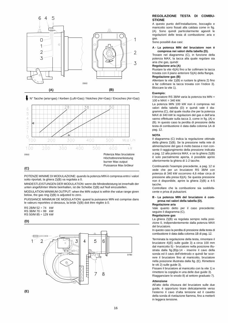
REGOLAZIONE TESTA DI COMBU-STIONEA questo punto dell’installazione, boccaglio emanicotto sono fissati alla caldaia come in fig.(A). Sono quindi particolarmente agevoli leregolazioni delle testa di combustione: aria egas.Sono possibili due casi:
A - La potenza MIN del bruciatore non ècompresa nei valori della tabella (D).
Trovare nel diagramma (C), in funzione dellapotenza MAX, la tacca alla quale regolare siaaria che gas, quindi:Regolazione aria (A)Ruotare la vite 4)(A) fino a far collimare la taccatrovata con il piano anteriore 5)(A) della flangia.Regolazione gas (B)Allentare la vite 1)(B) e ruotare la ghiera 2) finoa far collimare la tacca trovata con l’indice 3).Bloccare la vite 1).
Esempio:il bruciatore RS 38/M varia la potenza tra MIN =100 e MAX = 340 kW.La potenza MIN 100 kW non è compresa neivalori della tabella (D) e quindi vale il dia-gramma (C), dal quale risulta che per la potenzaMAX di 340 kW le regolazioni del gas e dell’ariavanno effettuate sulla tacca 3, come in fig. (A) e(B). In questo caso la perdita di pressione dellatesta di combustione è data dalla colonna 1A dipag. 12.
NOTAIl diagramma (C) indica la regolazione ottimaledella ghiera 2)(B). Se la pressione nella rete dialimentazione del gas è molto bassa e non con-sente il raggiungimento della pressione indicataa pag. 12 alla potenza MAX, e se la ghiera 2)(B)è solo parzialmente aperta, è possibile aprireulteriormente la ghiera di 1-2 tacche.
Continuando l’esempio precedente, a pag. 12 sivede che per un bruciatore RS 38/M conpotenza di 340 kW occorrono 4,6 mbar circa dipressione alla presa 6)(A). Se questa pressionenon è disponibile, aprire la ghiera 2)(B) a 4-5tacche.Controllare che la combustione sia soddisfa-cente e priva di pulsazioni.
B - La potenza MIN del bruciatore è com-presa nei valori della tabella (D).
Regolazione ariaVale quanto detto per il caso precedente:seguire il diagramma (C).Regolazione gasLa ghiera 2)(B) va regolata sempre nella posi-zione 0, indipendentemente dalla potenza MAXdel bruciatore.In questo caso la perdita di pressione della testa dicombustione è data dalla colonna 1B di pag. 12.
Terminata la regolazione della testa, rimontare ilbruciatore 4)(E) sulle guide 3) a circa 100 mmdal manicotto 5) - bruciatore nella posizione illu-strata dalla fig.(B)p.14 - inserire il cavo dellasonda ed il cavo dell’elettrodo e quindi far scor-rere il bruciatore fino al manicotto, bruciatorenella posizione illustrata dalla fig. (E). Rimetterele viti 2) sulle guide 3).Fissare il bruciatore al manicotto con la vite 1) erimettere la copiglia in una delle due guide 3).Riagganciare lo snodo 8) al settore graduato 7).
AttenzioneAll’atto della chiusura del bruciatore sulle dueguide, è opportuno tirare delicatamente versol’esterno il cavo d’alta tensione ed il cavettodella sonda di rivelazione fiamma, fino a metterliin leggera tensione.
(A)
(C)
(D)
(B)
N° Tacche (aria=gas) / Kerben (Luft=Gas) / Notches (Air=Gas) / Encoches (Air=Gaz)
POTENZE MINIME DI MODULAZIONE: quando la potenza MIN è compresa entro i valorisotto riportati, la ghiera 2)(B) va regolata a 0.
MINDESTLEISTUNGEN DER MODULATION: wenn die Mindestleistung ist innerhalb derunten angeführten Werte beinhalten, ist die Scheibe 2)(B) auf Null einzustellen.
MODULATION MINIMUM OUTPUT: when the MIN output is within the value range givenbelow, the gas ring 2)(B) is adjusted to zero.
PUISSANCE MINIMUM DE MODULATION: quand la puissance MIN est comprise dansle valeurs reportées ci-dessous, la bride 2)(B) doit être réglée à 0.
RS 28/M 52 ÷ 74 kWRS 38/M 70 ÷ 99 kWRS 50/M 85 ÷ 129 kW
(E)
Potenza Max bruciatoreHöchstbrennerleistungburner Max outputPuissance Max brûleur
D502
D503
D780
17
EINSTELLUNG DES FLAMMKOPFSAn dieser Stelle der Installation sind Flammrohrund Muffe gem. Abb. (A) am Kessel befestigt.Die Einstellungen des Flammkopfs ist daherbesonders bequem: die Lufteinstellung und dieGaseinstellung.Zwei Fälle sind möglich:
A - Die Mindestleistung des Brenners istnicht in den Werten der Tabelle (D) einge-schloßen.
In Diagramm (C), in Abhängigkeit der Höchst-brennerleistung, die Kerbe ausfinding machen,auf die Luft und Gas einzustellen sind, dann:Lufteinstellung (A) Die Schraube 4)(A) drehen, bis die gefundeneKerbe mit der Vorderfläche 5)(A) des Flanscheszusammenfällt.Gaseinstellung (B)Die Schraube 1)(B) lockern und die Scheibe 2)soweit drehen, bis die gefundene Kerbe mit demIndexstift 3) zusammenfällt.Die Schraube 1) blockieren.
Beispiel:der Brenner RS 38/M ändert die Leistung zwi-schen MIN = 100 und MAX = 340 kW.Die Mindestleistung von 100 kW ist nicht in denWerten der Tabelle (D) eingeschloßen, unddaher gilt das Diagramm (C), aus dem es sichergibt, daß für die Höchstleistung von 340 kWdie Gas- und Lufteinstellungen auf Kerbe 3 aus-zuführen sind, wie in Abb. (A) und (B) darge-stellt.In diesem Fall ist der Druckverluft des Flamm-kopfs in der Spalte 1A auf Seite 12 angegeben.
MERKEDas Diagramm (C) zeigt die optimale Einstel-lung der Scheibe 2)(B). Falls der Gaszulei-stungsdruck besonders niedrig ist und dadurchder auf Seite 12 angegebene Druck in derHöchstleistung nicht erreicht werden kann, undfalls die Scheibe 2)(B) nur teilweise geöffnet ist,kann die letztere um weitere 1-2 Kerben geöff-net werden.
Entsprechend diesem Beispiel ist auf Seite 12ersichtlich, daß ein Brenner RS 38/M mit 340kW Leistung ca. 4,6 mbar Druck an der Entnah-mestelle 6)(A) erfordert. Liegt dieser Druck nichtan, die Scheibe 2)(B) auf die 4-5 Kerbe öffnen.Die Verbrennung muß zufriedenstellend undohne Verpuffungen erfolgen.
B - Die Mindestleistung des Brenners ist inden Werten der Tabelle (D) eingeschloßen.
LufteinstellungEs gilt das gleiche wie im vorhergehenden Fall:dem Diagramm (C) folgen.GaseinstellungDie Scheibe 2)(B) ist immer auf Null einzustel-len, unabhängigkeit von der Höchstleistung desBrenners.In diesem Fall ist der Druckverlust des Flamm-kopfs unter Spalte 1B auf Seite 12 angegeben.
Nach Beendung der Flammkopfeinstellung denBrenner 4)(E) auf die Führungen 3) in ca. 100mm Abstand zum Brennerkopf 5) - einbauen -Brennerposition in Abb. (B)S.14 - das Fühler-und Elektrodenkabel einsetzen und anschlie-ßend den Brenner bis zur Muffe schieben, Bren-nerposition in Abb. (E).Die Schrauben 2) auf die Führungen 3) einset-zen.Den Brenner mit der Schraube 1) an der Muffebefestigen und den Splint in eine der zwei Füh-rungen 3) wieder einsetzen.Das Gelenk 8) wieder am Skalensegment 7)einhängen.
Wichtiger HinweisBeim Schließen des Brenners ist es ratsam, dasHochspannungskabel und das Kabel des Flam-menfühlers vorsichtig nach außen zu ziehen, bissie leicht gespannt sind.
SETTING THE COMBUSTION HEADInstallation operations are now at the stagewhere the blast tube and sleeve are secured tothe boiler as shown in fig. (A). Therefore it isparticulary easy to carry out the combustionhead adjustments: air and gas.There are two possible cases:
A - The MIN burner output is not in the val-ues of table (D).
In diagram (C), depending on the MAX output,find the notch to use for adjusting the air and thegas, and then proceed as follows:Air adjustment (A) Turn screw 4)(A) until the notch identified isaligned with the front surface 5)(A) of the flange.Gas adjustment (B)Loosen screw 1)(B) and turn ring 2) until thenotch identified is aligned with index 3).Tighten the screw 1) fully down.
Example:the burner RS 38/M varies its output between:MIN = 100 e MAX = 340 kW.The MIN output of 100 kW is not found in thevalues of table (D) and therefore diagramm (C)is valid, from which it results that for a MAX out-put of 340 kW the gas and air adjustments aredone on notch 3, as in fig. (A) and (B).In this case the pressure load loss of the com-bustion head is given by column 1A page 12.
NOTEDiagramm (C) shows the ideal settings for thering 2)(B). If the gas mains pressure is too lowto reach the max output operation pressure indi-cated on page 12, and if the ring 2)(B) is notfully open, it can be opened wider by 1 or 2notches.
Continuing with the previous example, page 12indicates that for burner RS 38/M with output of340 kW a pressure of approximately 4,6 mbar isnecessary at test point 6)(A). If this pressurecannot be reached, open the ring 2)(B) to notch4 or 5.Make sure that the combustion characteristicsare satisfactory and free of pulsations.
B - The MIN burner output is found in thevalues of the table (D).
Air adjustmentThe same as the previous case: follow dia-gramm (C).Gas adjustmentThe gas ring 2)(B) is always adjusted to position0, irrespective of the MAX burner.In this case the pressure load loss of the com-bustion heads is given by column 1B page 12.
Once you have finished setting up the head, refitthe burner 4)(E) to the slide bars 3) at approxi-mately 100 mm from the sleeve 5) - burner posi-tioned as shown in fig. (B)p.14 - insert the flamedetection probe cable and the ignition electrodecable and then slide the burner up to the sleeveso that it is positioned as shown in fig. (E).Refit screws 2) on slide bars 3).Secure the burner to the sleeve by tighteningscrew 1) and then refit the split pin into one oftwo slide bars 3).Reconnect the articulation 8) to the graduatedsector 7).
ImportantWhen fitting the burner on the two slide bars, itis advisable to gently draw out the high tensioncable and flame detection probe cable until theyare slightly stretched.
REGLAGE TETE DE COMBUSTIONA ce stade de l'installation, buse et manchonsont fixés à la chaudière comme indiqué sur lafig. (A). Le réglage de la tête de combustion: air et gaz est donc facilité au maximum.Il y a deux cas possibles:
A - La puissance MIN du brûleur n’est pascomprise dans les valeurs du tableau (D).
Trouver sur le diagramme (C), en fonction de lapuissance MAX, l’encoche sur laquelle réglerl’air et le gaz.Réglage de l'air (A) Faire pivoter la vis 4)(A) jusqu'à faire correspon-dre l'encoche trouvée avec le plan antérieur5)(A) de la bride.Réglage du gaz (B)Desserrer la vis 1)(B) et faire tourner la bague2) jusqu’à faire correspondre l’encoche avec lerepère 3). Bloquer les vis 1).
Exemple:le brûleur RS 38/M varie la puissance entre:MIN = 100 e MAX = 340 kW.La puissance MIN 100 kW n’est pas comprisedans les valeurs du tableau (D), le diagramme(C), à partir duquel il résulte que pour la puis-sance MAX de 340 kW les réglages du gaz etde l’air doivent être effectués sur l’encoche 3,comme indiqué sur les fig. (A) et (B), est doncvalable.Dans ce cas, la perte de pression de la tête decombustion est donnée par la colonne 1A à lapage 12.
NOTELe diagramme (C) indique le réglage optimal dela bague 2)(B). Si la pression du réseau d’ali-mentation en gaz est très faible et ne permetpas d’atteindre la pression indiquée page 12 àla puissance maximum, et si la bague 2)(B)n’est ouverte qu’en partie, il est possible d’ouvirencore cette bague de 1 ou 2 encoches.
Pour continuer l'exemple précédent, la page 12indique que pour un brûleur RS 38/M ayant unepuissance de 340 kW il faut 4,6 mbar environ depression à la prise 6)(A). Si cette pression n’estpas disponible, ouvrir la bague 2)(B) de 4 ou 5encoches.Contrôler que la combustion soit satisfaisante etsans saccades.
B - La puissance MIN du brûleur est com-prise dans les valeurs du tableau (D).
Réglage de l’airMême chose que pour le cas précédent: suivrele diagramme (C).Réglage du gazLa bague 2)(B) doit toujours être réglée en posi-tion 0, indépendamment de la puissance MAXdu brûleur.Dans ce cas, la perte de pression de la tête decombustionest donnée par la colonne 1B à lapage 12.
Une fois terminé le réglage de la tête, remonterle brûleur 4)(E) sur les guides 3) à environ 100mm du manchon 5) - brûleur dans la positionillustrée fig. (B)p.14 - placer les câbles de lasonde et de l'électrode et ensuite faire coulisserle brûleur jusqu'au manchon, brûleur dans laposition illustrée fig. (E).Replacer les vis 2) sur les guides 3).Fixer le brûleur au manchon avec la vis 1) et rem-placer la goupille dans un des deux guides 3).Raccrocher la rotule 8) au secteur gradué 7).
AttentionAu moment de la fermeture du brûleur sur lesdeux guides, il faut tirer délicatement vers l'exté-rieur le câble de haute tension et le petit câblede la sonde de détection flamme, jusqu'à cequ'ils soient légèrement tendus.

18
LINEA ALIMENTAZIONE GAS• La rampa del gas va collegata all’attacco del
gas 1)(A), tramite la flangia 2), la guarnizione3) e le viti 4) date a corredo del bruciatore.
• La rampa può arrivare da destra o da sinistra,secondo comodità, vedi fig. (A).
• Le elettrovalvole 8)-9)(B) del gas devonoessere il più vicino possibile al bruciatore inmodo da assicurare l'arrivo del gas alla testadi combustione nel tempo di sicurezza di 2 s.
• Assicurarsi che il campo di taratura del regola-tore di pressione (colore della molla) com-prenda la pressione necessaria al bruciatore.
RAMPA GAS (B)E' omologata secondo norma EN 676 e vienefornita separatamente dal bruciatore con ilcodice indicato in tab. (C).
LEGENDA (B)1 - Condotto arrivo del gas2 - Valvola manuale3 - Giunto antivibrante4 - Manometro con rubinetto a pulsante5 - Filtro6 - Regolatore di pressione (verticale)7 - Pressostato gas di minima8 - Elettrovalvola di sicurezza VS (verticale)9 - Elettrovalvola di regolazione VR (verticale)
Due regolazioni:• portata d'accensione (apertura rapida)• portata massima (apertura lenta)
10 - Guarnizione e flangia a corredo bruciatore11 - Farfalla regolazione gas 12 - Bruciatore13 - Dispositivo di controllo tenuta valvole 8)-9).
Secondo la norma EN 676 il controllo ditenuta è obbligatorio per i bruciatori conpotenza massima superiore a 1200 kW.
14 - Adattatore rampa-bruciatore15 - Pressostato gas di massima
P1 - Pressione alla testa di combustioneP2 - Pressione a valle del regolatoreP3 - Pressione a monte del filtro
L - Rampa gas fornita a parte con il codiceindicato in tab. (C).
L1 - A cura dell'installatore
LEGENDA TABELLA (C)C.T.= Dispositivo controllo tenuta valvole gas
8) - 9):- = Rampa priva del dispositivo di con-
trollo tenuta; dispositivo che puòessere ordinato a parte, vedi colonna13, e montato successivamente.
♦ = Rampa con il dispositivo di controllotenuta VPS montato.
13 = Dispositivo di controllo tenuta valvoleVPS.Fornito su richiesta separatamente dallarampa gas.
14 = Adattatore rampa-bruciatore.Fornito su richiesta separatamente dallarampa gas.
NotaPer la regolazione della rampa gas vedere leistruzioni che l'accompagnano.
(A)
BRUCIATORI E RELATIVE RAMPE GAS OMOLOGATE SECONDO NORMA EN 676GASBRENNER UND ZUGEHÖRIGE NACH EN 676 TYPGEPRÜFTE GASARMATURENGAS BURNERS AND RELEVANT GAS TRAINS APPROVED ACCORDING TO EN 676BRULEURS ET RELATIVES RAMPES GAZ HOMOLOGUEES SELON LA NORME EN 676
RAMPE - GASARMATURENGAS TRAINS - RAMPE GAZ L
BRUCIATORE - BRENNERBURNER - BRULEUR
13 14
Ø C.T. Code RS 28/M RS 38/M RS 50/M Code Code3/4” - 3970076 • - - 3010123 30008241” - 3970077 • • • 3010123 3000824
1”1/4 - 3970144 • • • 3010123 -1”1/2 - 3970145 • • • 3010123 -1”1/2 - 3970180 • • • 3010123 -
2”2”
-♦
39701463970160
--
••
••
3010123-
30008223000822
2”2”
-♦
39701813970182
--
••
••
3010123-
30008223000822
(B)
COMPONENTI RAMPA GAS - BESTANDTEILE GASARMATURENGAS TRAINS COMPONENTS - COMPOSANTS RAMPE GAZ
COD.
COMPONENTI - BESTANDTEILE COMPONENTS - COMPOSANTS
5 6 8 - 9
3970076 Multiblock MB DLE 407
3970077 Multiblock MB DLE 410
3970144 Multiblock MB DLE 412
3970145 GF 515/1 FRS 515 DMV DLE 512/11
3970180 Multiblock MB DLE 415
39701463970160
GF 520/1 FRS 520 DMV DLE 520/11
39701813970182
Multiblock MB DLE 420
(C)
D505
D1062

19
GASZULEITUNG• Gasarmaturen sind über Flansch 2), Dichtung
3) und Schrauben 4), zur Brennerausstattunggehörend, mit dem Gasanschluß 1)(A) zu ver-binden.
• Die Armatur kann je nach Bedarf von rechtsbzw. links zugeführt werden, s. Abb. (A).
• Die Gasmagnetventile 8)-9)(B) der Gaszulei-stung sollen so nah wie möglich am Brennerliegen, damit die Gaszufuhr zum Flammkopfinnerhalb 2 Sekunden sichergestellt ist.
• Überprüfen, ob der Einstellbereich des Druck-reglers (Farbe der Feder) die für den Brennererforderlichen Druckwerte vorsieht.
GASARMATUREN (B)Nach Norm EN 676 typgeprüft, wird gesondertmit dem in Tab. (C) angegebenen Code gelie-fert.
ZEICHENERKLÄRUNG (B)1 - Gaszuleitung2 - Handbetätigtes Ventil3 - Kompensator4 - Manometer mit Druckknopfhahn5 - Filter6 - Druckregler (senkrecht)7 - Gas-Minimaldruckwächter8 - Sicherheitsmagnetventil VS (senkrecht)9 - Regelmagnetventil VR (senkrecht)
Zwei Einstellungen:• Zünddurchsatz (schnellöffnend)• Max. Durchsatz (langsamöffnend)
10 - Dichtung und Flansch Brennergrundaus-stattung
11 - Gas-Einstelldrossel 12 - Brenner13 - Dichtheitskontrolleinrichtung der Gasven-
tile 8)-9). Laut Norm EN 676 ist die Dicht-heitskontrolle für Brenner mitHöchstleistung über 1200 kW Pflicht.
14 - Passtück Armatur-Brenner15 - Gas-Höchstdruckwächter
P1 - Druck am FlammkopfP2 - Druck nach dem ReglerP3 - Druck vor dem Filter
L - Gasarmatur gesondert mit dem in Tab. (C)angegebenen Code geliefert.
L1 - Vom Installateur auszuführen
ZEICHENERKLÄRUNG TABELLE (C)C.T.= Dichtheitskontrolleinrichtung der Gasven-
tile 8) - 9):- = Gasarmatur ohne Dichtheitskontroll-
einrichtung; die Einrichtung kanngesondert bestellt, siehe Spalte 13,und später eingebaut werden.
♦ = Gasarmatur mit der eingebauten Dichtheitskontrolleinrichtung VPS.
13 = Dichtheitskontrolleinrichtung VPS derGasventile.Auf Anfrage gesondert von der Gasarma-tur lieferbar.
14 = Passtück Armatur-Brenner.Auf Anfrage gesondert von der Gasarma-tur lieferbar.
MerkeZur Einstellung der Gasarmaturen siehe die bei-gelegten Anleitungen.
GAS LINE• The gas train must be connected to the gas
attachment 1)(A), using flange 2), gasket 3)and screws 4) supplied with the burner.
• The gas train can enter the burner from theright or left side, depending on which is themost convenient, see fig. (A).
• The gas solenoids 8)-9)(A) must be as closeas possible to the burner to ensure gasreaches the combustion head within the safetytime range of 2 s.
• Make sure that the pressure governor calibra-tion range (colour of the spring) comprises thepressure required by the burner.
GAS TRAIN (A)It is type-approved according to EN 676 Stand-ards and is supplied separately from the burnerwith the code indicated in Table (C).
KEY (A)1 - Gas input pipe2 - Manual valve3 - Vibration damping joint4 - Pressure gauge with pushbutton cock5 - Filter6 - Pressure governor (vertical)7 - Minimum gas pressure switch8 - Safety solenoid VS (vertical)9 - Adjustment solenoid VR (vertical)
Two adjustments:• ignition delivery (rapid opening)• maximum delivery (slow opening)
10 - Standard issue burner gasket with flange11 - Gas adjustment butterfly valve12 - Burner13 - Gas valve 8)-9) leak detection control
device.In accordance with EN 676 Standards, gasvalve leak detection control devices arecompulsory for burners with maximum out-puts of more than 1200 kW.
14 - Gas train/burner adaptor15 - Maximum gas pressure switch
P1 - Pressure at combustion headP2 - Pressure down-line from the pressure gov-
ernorP3 - Pressure up-line from the filter
L - Gas train supplied separately with the codeindicated in table (C)
L1 - The responsibility of the installer
KEY TO TABLE (C)C.T.= Gas valves 8)-9) leak detection control
devices:- = Gas train without gas valve leak
detection control device; device thatcan be ordered separately andassembled subsequently (see Col-umn 13).
♦ = Gas train with assembled VPS valveleak detection control device.
13 = VPS valve leak detection control device.Supplied separately from gas train onrequest.
14 = Gas train/burner adaptor.Supplied separately from gas train onrequest.
NoteSee the accompanying instructions for theadjustment of the gas train.
LIGNE ALIMENTATION GAZ• La rampe du gaz doit être reliée au raccord du
gaz 1)(A), par la bride 2), le joint 3) et les vis 4)fournis de série avec le brûleur.
• La rampe peut arriver par la droite ou par lagauche selon les cas, comme indiqué sur lafig. (A).
• Les électrovannes 8)-9)(B) du gaz doivent êtrele plus près possible du brûleur de façon àassurer l'arrivée du gaz à la tête de combus-tion en un temps de sécurité de 2 s.
• Contrôler que la plage de réglage du régula-teur de pression (couleur du ressort) recouvrela pression nécessaire au brûleur.
RAMPE GAZ (B)Elle est homologuée suivant la norme EN 676 etelle est fournie séparément du brûleur avec lecode indiqué dans le tableau (C).
LEGENDA (B)1 - Canalisation d'arrivée du gaz2 - Vanne manuelle3 - Joint anti-vibrations4 - Manomètre avec robinet à bouton poussoir5 - Filtre6 - Régulateur de pression (vertical)7 - Pressostat gaz de seuil minimum8 - Electrovanne de sécurité VS (verticale)9 - Electrovanne de régulation VR (verticale)
Deux réglages:• débit d'allumage (ouverture rapide)• débit maximum (ouverture lente)
10 - Joint et bride fournis avec le brûleur11 - Papillon réglage gaz 12 - Brûleur13 - Dispositif de contrôle d'étanchéité vannes
8)-9).Selon la norme EN 676, le contrôle d'étan-chéité est obligatoire pour les brûleursayant une puissance maximale supérieureà 1200 kW.
14 - Adaptateur rampe-brûleur15 - Pressostat gaz seuil maximum
P1 - Pression à la tête de combustionP2 - Pression en aval du régulateurP3 - Pression en amont du filtre
L - La rampe gaz est fournie à part avec lecode indiqué dans le tab. (C).
L1 - A la charge de l'installateur
LEGENDE TABLEAU (C)C.T.= Dispositif de contrôle d'étanchéité vannes
8)-9):- = Rampe sans dispositif de contrôle
d'étanchéité; dispositif qui peut êtrecommandé à part et monté par lasuite, voir colonne 13.
♦ = Rampe avec dispositif de contrôled'étanchéité VPS monté.
13 = Dispositif VPS de contrôle d'étanchéité dela vanne.Fourni sur demande séparément de larampe gaz.
14 = Adaptateur rampe-brûleur.Fourni sur demande séparément de larampe gaz.
NotePour le réglage de la rampe gaz voir les instruc-tions qui l'accompagnent.

20
IMPIANTO ELETTRICO
IMPIANTO ELETTRICO eseguito in fabbrica
SCHEMA (A)Bruciatore RS 28/M (monofase)
SCHEMA (B)Bruciatore RS 38/M - 50/M (trifase)• I modelli RS 38/M e RS 50/M trifase lasciano
la fabbrica previsti per alimentazione elettrica400 V.
• Se l'alimentazione è 230 V, cambiare il colle-gamento del motore (da stella a triangolo) e lataratura del relè termico.
LEGENDA SCHEMI (A) - (B)C - CondensatoreCMV - Contattore motoreF1 - Filtro contro radiodisturbiLFL 1.3.. - Apparecchiatura elettricaMB - Morsettiera bruciatoreMV - Motore ventilatorePA - Pressostato ariaPGM - Pressostato gas di massimaRT - Relè termicoS1 - Interruttore per funzionamento:
MAN = manualeAUT = automaticoOFF = spento
S2 - Pulsante per- = diminuzione potenza+ = aumento potenza
SM - ServomotoreSO - Sonda di ionizzazioneSP - Spina-presaTA - Trasformatore d'accensioneTB - Terra bruciatore
COLLEGAMENTI ELETTRICIUsare cavi flessibili secondo norma EN 60 335-1:• se sotto guaina di PVC almeno tipo H05 VV-F• se sotto guaina di gomma almeno tipo H05
RR-F.
Tutti i cavi da collegare alla morsettiera 7)(C) delbruciatore vanno fatti passare dai passacavi for-niti a corredo da inserire nei fori della piastrina,di destra o di sinistra, dopo aver svitato le viti 8),aperto la piastrina nelle parti 9) e 10) ed aspor-tato il sottile diaframma che chiude i fori.L'utilizzo dei passacavi e dei fori pretranciati puòavvenire in vari modi; a scopo esemplificativoindichiamo il modo seguente:
RS 28/M1- Pg 11 Alimentazione monofase2- Pg 11 Valvole gas
(quando non è montato il controllodi tenuta RG1/CT o LDU 11)
3- Pg 9 Telecomando TL4- Pg 9 Telecomando TR o sonda
(RWF40)5- Pg 11 Pressostato gas o controllo tenuta
valvole
RS 38/M - RS 50/M1- Pg 11 Alimentazione trifase 2- Pg 11 Alimentazione monofase3- Pg 9 Telecomando TL4- Pg 9 Telecomando TR o sonda
(RWF40)5- Pg 11 Valvole gas
(quando non è montato il controllodi tenuta RG1/CT o LDU 11)
6- Pg 11 Pressostato gas o controllo tenutavalvole
(A)
IMPIANTO ELETTRICO ESEGUITO IN FABBRICAWERKSEITIG AUSGEFÜHRTE ELEKTROANLAGEELECTRICAL EQUIPMENT FACTORY-SETINSTALLATION ELECTRIQUE REALISEE EN USINERS 28/M
IMPIANTO ELETTRICO ESEGUITO IN FABBRICAWERKSEITIG AUSGEFÜHRTE ELEKTROANLAGEELECTRICAL EQUIPMENT FACTORY-SETINSTALLATION ELECTRIQUE REALISEE EN USINERS 38/M - RS 50/M
(B)
(C)
D1063
D1064
D1065

21
ELEKTROANLAGE
ELEKTROANLAGE werkseitig ausgeführt
SCHEMA (A)Brenner RS 28/M (einphasing)
SCHEMA (B)Brenner RS 38/M - 50/M (dreiphasing)• Die Modelle RS 38/M und RS 50/M drei-
phasing werden werkseitig für 400 V Stromver-sorgung vorbereitet.
• Falls die Stromversorgung 230 V beträgt, denMotoranschluß (Stern- oder Dreieckschaltung)und die Einstellung des Überstromauslöserverändern.
ERLÄUTERUNG SCHEMEN (A) - (B)C - KondensatorCMV - MotorkontaktgeberF1 - FunkentstörerLFL 1.3.. - SteuergerätMB - Klemmenbrett BrennerMV - GebläsemotorPA - LuftdruckwächterPGM - Gas-HöchstdruckwächterRT - ÜberstromauslöserS1 - Schalter für:
MAN = Manueller BetriebAUT = Automatischer BetriebOFF = AUS
S2 - Schalter für:- = Leistungsabminderung+ = Leistungserhöhung
SM - StellantriebSO - IonisationselektrodeSP - SteckanschlußTA - ZündtransformatorTB - Brennererdung
ELEKTROANSCHLÜSSE Gemäß Norm EN 60 335-1 biegsame Kabel ver-wenden:• falls unter PVC-Mantel mindestens den Typ
H05 VV-F verwenden.• falls unter Gummimantel mindestens den Typ
H05 RR-F verwenden.
Alle an das Klemmenbrett 7)(C) anzuschließen-den Kabel sind durch die beigepackten Kabel-durchgänge zu führen, die nach Abdrehen derSchrauben 8), Öffnen der Kabeldurchführung 9)und 10) und Abnahme der Verschlußblende indie Bohrungen der rechten oder linken Platteeingesteckt werden.Die Kabeldurchgänge und Vorbohrungen kön-nen auf verschiedene Art verwendet werden;hier ein Beispiel:
RS 28/M1- Pg 11 Einphasenspeisung2- Pg 11 Gasventile
(wenn die Dichtheitskontrollein-richtung RG1/CT oder LDU 11nicht eingebaut ist)
3- Pg 9 TL-Regelung4- Pg 9 TR-Regelung oder Fühler
(RWF40)5- Pg 11 Gasdruckwächter oder Dichtheits-
kontrolle der Gasventile
RS 38/M - RS 50/M1- Pg 11 Dreiphasenspeisung2- Pg 11 Einphasenspeisung3- Pg 9 TL-Regelung4- Pg 9 TR-Regelung oder Fühler
(RWF40)5- Pg 11 Gasventile
(wenn die Dichtheitskontrollein-richtung RG1/CT oder LDU 11nicht eingebaut ist)
6- Pg 11 Gasdruckwächter oder Dichtheits-kontrolle der Gasventile
ELECTRICAL SYSTEM
ELECTRICAL SYSTEM as set up by the manu-facturer
LAYOUT (A)Burner RS 28/M (single-phase)
LAYOUT (B)Burner RS 38/M - 50/M (three-phase)• Models RS 38/M and RS 50/M three-phase
leave the factory preset for 400 V power sup-ply.
• If 230 V power supply is used, change themotor connection from star to delta andchange the setting of the thermal cut-out aswell.
KEY TO LAYOUTS (A) - (B)C - CapacitorCMV - Motor contactorF1 - Protection against radio interfer-
enceLFL 1.3.. - Control boxMB - Burner terminal stripMV - Fan motorPA - Air pressure switchPGM - Maximum gas pressure switchRT - Thermal cut-outS1 - Switch for following operations:
MAN = manualAUT = automaticOFF
S2 - Button for:- = power reduction+ = power increase
SM - ServomotorSO - Ionisation probeSP - Plug-socketTA - Ignition transformerTB - Burner ground
ELECTRICAL CONNECTIONSUse flexible cables according to EN 60 335-1Regulations:• if in PVC sheath, use at least H05 VV-F• if in rubber sheath, use at least H05 RR-F.
All the wires to connect to the burner terminalstrip 7)(C) must enter through the supplied fair-leads, which must be fitted into the relevantholes in the left hand or right hand plate. To dothis, first unscrew screws 8), then split the plateinto its two parts 9) and 10) and remove themembrane press-outs from the holes.The fairleads and hole press-outs can be usedin various ways; the following lists show onepossible solution:
RS 28/M1- Pg 11 Single-phase power supply2- Pg 11 Gas valves
(when RG1/CT or LDU 11 leakdetection control device is not fitted)
3- Pg 9 Remote control device TL4- Pg 9 Remote control device TR or
probe (RWF40)5- Pg 11 Gas pressure switch or gas valve
leak detection control device
RS 38/M - RS 50/M1- Pg 11 Three-phase power supply2- Pg 11 Single-phase power supply3- Pg 9 Remote control device TL4- Pg 9 Remote control device TR or
probe (RWF40)5- Pg 11 Gas valves
(when RG1/CT or LDU 11 leakdetection control device is not fitted)
6- Pg 11 Gas pressure switch or gas valveleak detection control device
INSTALLATION ELECTRIQUE
INSTALLATION ELECTRIQUE effectué enusine
SCHEMA (A)Brûleur RS 28/M (monophasé)
SCHEMA (B)Brûleur RS 38/M - 50/M (triphasés)• Le modèle RS 38/M et RS 50/M triphasés quit-
tent l'usine prévus pour une alimentation élec-trique à 400 V.
• Si l'alimentation est à 230 V, modifier le bran-chement du moteur (d'étoile à triangle) et leréglage du relais thermique.
LEGENDE SCHEMAS (A) - (B)C - CondensateurCMV - Contacteur moteurF1 - Protection contre parasites radioLFL 1.3.. - Coffret de sécuritéMB - Porte-bornes brûleursMV - Moteur ventilateurPA - Pressostat airPGM - Pressostat gaz seuil maximumRT - Relais thermiqueS1 - Interrupteur pour le fonctionner:
MAN = manuelAUT = automatiqueOFF = éteint
S2 - Bouton-poussoir pour:- = diminution puissance+ = augmentation puissance
SM - ServomoteurSO - Sonde d'ionisationSP - Fiche-priseTA - Transformateur d'allumageTB - Mise à la terre brûleur
BRANCHEMENTS ELECTRIQUESUtiliser des câbles flexibles selon la norme EN60 335-1:• si en gaine PVC, au moins type H05 VV-F• si en gaine caoutchouc, au moins type H05
RR-F.
Tous les câbles à brancher au bornier 7)(C) dubrûleur doivent passer par les passe-câbles desérie à insérer dans les orifices pratiqués dansla plaque, de gauche ou de droite, après avoirdesserré les vis 8), ouvert la plaque parties 9) et10) et retiré le fin diaphragme recouvrant lestrous. L'utilisation des passe-câbles et des trousprédécoupés peut se faire de plusieurs façons;à titre d'exemple nous indiquons l'une de cespossibilités:
RS 28/M1- Pg 11 Alimentation monophasée2- Pg 11 Vannes gaz
(lorsque le contrôle d'étanchéité RG1/CT ou LDU 11 n'est pas monté)
3- Pg 9 Télécommande TL4- Pg 9 Télécommande TR ou sonde
(RWF40)5- Pg 11 Pressostat gaz ou contrôle d'étan-
chéité vannes gaz
RS 38/M - RS 50/M1- Pg 11 Alimentation triphasée2- Pg 11 Alimentation monophasée3- Pg 9 Télécommande TL4- Pg 9 Télécommande TR ou sonde
(RWF40)5- Pg 11 Vannes gaz
(lorsque le contrôle d'étanchéitéRG1/CT ou LDU 11 n'est pas monté)
6- Pg 11 Pressostat gaz ou contrôle d'étan-chéité vannes gaz

22
SCHEMA (A) - Alimentazione monofaseAllacciamento elettrico bruciatore RS 28/Msenza controllo tenuta valvole gas.
SCHEMA (B) - Alimentazione monofaseAllacciamento elettrico bruciatori RS 28/Mcon controllo tenuta valvole gas VPS.Il controllo tenuta valvole gas avviene subitoprima di ogni avviamento del bruciatore.
SCHEMA (C) - Alimentazione trifaseAllacciamento elettrico bruciatori RS 38/M -50/M senza controllo tenuta valvole gas.
SCHEMA (D) - Alimentazione trifaseAllacciamento elettrico bruciatori RS 38/M -50/M con controllo tenuta valvole gasVPS.Il controllo tenuta valvole gas avviene subitoprima di ogni avviamento del bruciatore.
LEGENDA SCHEMI (A) - (B) - (C) - (D)IN - Interruttore elettrico per arresto manuale
bruciatoreMB - Morsettiera bruciatoreXP - Spina per controllo di tenutaPG - Pressostato gas di min.S - Segnalazione di blocco a distanzaS1 - Segnalazione di blocco del controllo di
tenuta a distanzaTR - Telecomando di regolazione:
comanda 1° e 2° stadio di funzionamento.TL - Telecomando di limite:
ferma il bruciatore quando la temperaturao la pressione in caldaia raggiunge ilvalore prestabilito.
TS - Telecomando di sicurezza: interviene in caso di TL guasto.
VR - Valvola di regolazioneVS - Valvola di sicurezza
NOTAI telecomandi TR e TL non sono necessariquando è collegato il RWF40 per funzionamentomodulante; la loro funzione viene svolta dalRWF40 stesso.
(A)
(C)
(D)
RS 28/M Monofase / einphasig / single-phase / monophasé
RS 38/M - RS 50/M Trifase / dreiphasig / triple-phase / triphasés
RS 28/M Monofase / einphasig / single-phase / monophasé
(B)
RS 38/M - RS 50/M Trifase / dreiphasig / triple-phase / triphasés
D1066
D1067
D1068
D1069

23
SCHEMA (A) - EinphasenspeisungElektroanschluß der Brenner RS 28/M ohneDichtheitskontrolle der Gasventile.
SCHEMA (B) - EinphasenspeisungElektroanschluß der Brenner RS 28/M mitDichtheitskontrolle VPS der Gasventile.Die Dichtheitskontrolle der Gasventile erfolgtumgehend vor jedem Brennerstart.
SCHEMA (C) - DreiphasenspeisungElektroanschluß der Brenner RS 28/M - 50/Mohne Dichtheitskontrolle der Gasventile.
SCHEMA (D) - DreiphasenspeisungElektroanschluß der Brenner RS 28/M - 50/Mmit Dichtheitskontrolle VPS der Gasventile.Die Dichtheitskontrolle der Gasventile erfolgtumgehend vor jedem Brennerstart.
ZEICHENERKLÄRUNG SCHEMEN (A) - (B) - (C) - (D)IN - Schalter für das manuelle Ausschalten
des BrennersMB - Klemmbrett BrennerXP - Stecker für die Dichtheitskontrolleinrich-
tungPG - Gas-MindestdruckwächterS - Störabschaltung-Fernmeldung S1 - Fernmeldung Störabschaltung Dichtheits-
kontrolleTR - Einstell-Fernsteuerung:
steuert 1. und 2. BetriebsstufeTL - Begrenzungsfernsteuerung:
schaltet den Brenner aus, wenn die Tem-peratur oder der Kesseldruck den festge-legten Wert erreichen.
TS - Sicherheitsfernsteuerung:tritt bei Defekt an TL in Aktion.
VR - RegelventilVS - Sicherheitsventil
MERKEWenn das RWF40 für den modulierendenBetrieb angeschlossen ist, sind die Fernsteue-rungen TR und TL nicht erforderlich, da derenFunktionen vom RWF40 übernommen werden.
LAYOUT (A) - The RS 28/M Modelelectrical connection single-phase powersupply without leak detection control device.
LAYOUT (B) - The RS 28/M Modelelectrical connection single-phase powersupply with VPS leak detection controldevice.Gas valve leak detection control takes placeimmediately before every burner start-up.
LAYOUT (C) - The RS 28/M - 50/M Modelselectrical connection three-phase powersupply without leak detection control device.
LAYOUT (D) - The RS 28/M - 50/M Modelselectrical connection three-phase powersupply with VPS leak detection controldevice.Gas valve leak detection control takes placeimmediately before every burner start-up.
KEY TO LAYOUTS (A) - (B) - (C) - (D)IN - Burner manual stop switchMB - Burner terminal stripXP - Plug for leak detection control devicePG - Min. gas pressure switchS - Remote lock-out signalS1 - Remote lock-out signal of leak detection
control deviceTR - High-low mode load remote control system:
controls operating stages 1 and 2.TL - Load limit remote control system:
shuts down the burner when the boilertemperature or pressure reaches the pre-set value.
TS - Safety load control system: operates when TL is faulty.
VR - Adjustment valveVS - Safety valve
NOTAThe TR and TL load controls are not requiredwhen the RWF40 is connected, as their functionis performed by the RWF40 itself.
SCHEMA (A) - Alimentation monophaséeBranchement électrique brûleur RS 28/Msans dispositif de contrôle d'étanchéité.
SCHEMA (B) - Alimentation monophaséeBranchement électrique brûleur RS 28/Mavec dispositif de contrôle d'étanchéité VPS.Le contrôle d'étanchéité des vannes se fait justeavant chaque mise en marche du brûleur.
SCHEMA (C) - Alimentation triphaséeBranchement électrique brûleur RS 38/M -50/M sans dispositif de contrôle d'étan-chéité.
SCHEMA (D) - Alimentation triphaséeBranchement électrique brûleur RS 38/M -50/M avec dispositif de contrôle d'étanchéitéVPS.Le contrôle d'étanchéité des vannes se fait justeavant chaque mise en marche du brûleur.
LEGENDE SCHEMAS (A) - (B) - (C) - (D)IN - Interrupteur électrique pour arrêt manuel
brûleurMB - Porte-bornes brûleurXP - Fiche pour le contrôle d'étanchéitéPG - Pressostat gaz seuil minimumS - Signalisation blocage brûleur à distanceS1 - Signalisation blocage contrôle d'étan-
chéité à distanceTR - Télécommande de réglage:
commande 1ère et 2ème allure de fonc-tionnement.
TL - Télécommande de limite: arrête le brûleur quand la température oula pression dans la chaudière a atteint lavaleur fixée.
TS - Télécommande de sécurité: intervient quand le TL tombe en panne
VR - Vanne de réglageVS - Vanne de sécurité
REMARQUELes télécommandes TR et TL ne sont pasnécessaires quand le RWF40, pour fonctionne-ment modulant, est branché: leur fonction estassurée par le RWF40 proprement dit.

24
SCHEMA (A)Allacciamento elettrico bruciatori RS 28-38-50/M con controllo tenuta valvole gas RG1/CT RIELLO.Il controllo tenuta valvole gas avviene subitoprima di ogni avviamento del bruciatore.
SCHEMA (C)Allacciamento elettrico bruciatori RS 28-38-50/M con controllo tenuta valvole gas LDU 11LANDIS.Il controllo tenuta valvole gas avviene subitoprima di ogni avviamento del bruciatore.
SCHEMA (B) - (D)Se si preferisce che il dispositivo RG1/CT o LDU11 controlli la tenuta delle valvole gas subitodopo l’arresto del bruciatore, collegare TL ed ildispositivo come in (B) - (D).
Legenda schemi (A) - (B) - (C) - (D) - (E)BT - Sonda di temperaturaBP - Sonda di pressioneMB - Morsettiera bruciatorePC - Pressostato gas per controllo di tenutaPG - Pressostato gas di min.TL - Telecomando di limite:
ferma il bruciatore quando la temperatura ola pressione in caldaia raggiunge il valoreprestabilito.
VR - Valvola di regolazioneVS - Valvola di sicurezza
SCHEMA (E)Allacciamento elettrico regolatore di potenzaRWF40 e relativa sonda ai bruciatori RS 28-38-50/M (funzionamento modulante).
NotaI telecomandi TR e TL non sono necessariquando è collegato il RWF40 per funzionamentomodulante; la loro funzione viene svolta dalregolatore stesso.
Il relè k1 (RWF40) può essere collegato ai mor-setti:- 2 - 3, per sostituire il telecomando TL- AL - AL1 ,per comandare un dispositivo di
allarme
SCHEMA (F)Taratura rele' termico 20)(A)p.8Serve ad evitare la bruciatura del motore per unforte aumento dell'assorbimento dovuto allamancanza di una fase.• Se il motore è alimentato a stella, 400 V, il cur-
sore va posizionato sul "MIN".• Se è alimentato a triangolo, 230 V, il cursore va
posizionato sul "MAX".Se la scala del relè termico non comprendel'assorbimento di targa del motore a 400 V, laprotezione è assicurata lo stesso.
NotaI modelli RS 38-50/M lasciano la fabbrica previ-sti per alimentazione elettrica 400 V. Se l'alimen-tazione è 230 V, cambiare il collegamento delmotore (da stella a triangolo) e la taratura delrelè termico.
I bruciatori RS 28-38-50/M sono stati omologatiper funzionamento intermittente. Ciò significache devono fermarsi "per Norma" almeno 1volta ogni 24 ore per permettere all'apparec-chiatura elettrica di effettuare un controllo dellapropria efficienza all'avviamento. Normalmentel'arresto del bruciatore viene assicurato dal tele-comando della caldaia.Se così non fosse è necessario applicare in seriea IN un interruttore orario che provveda all'arre-sto del bruciatore almeno 1 volta ogni 24 ore.Questi bruciatori sono adatti anche al funziona-mento continuo se vengono equipaggiati conl’apparecchiatura Landis LGK 16.333 A27(intercambiabile con l’apparecchiatura LandisLFL 1.333 del bruciatore).ATTENZIONE: Non invertire il neutro con la fase nella lineadi alimentazione elettrica.
(C)
(F)
(D)
(E)
a - d : Rosso Rot Red Rougeb - c : Bianco Weiss White Blanc
RELÈ TERMICOTHERMORELAISTHERMAL RELAYRELAIS THERMIQUE
RS 28/M - RS 38/M - RS 50/M
(A) (B)
RWF40
RS 28/M - RS 38/M - RS 50/M
D1070
D1071
D1910
D867

25
SCHEMA (A) Elektroanschluß der Brenner RS 28-38-50/Mmit Dichtheitskontrolle RG1/CT RIELLO.Die Dichtheitskontrolle der Gasventile erfolgtumgehend vor jedem Brennerstart.
SCHEMA (C) Elektroanschluß der Brenner RS 28-38-50/Mmit Dichtheitskontrolle LDU 11 LANDIS.Die Dichtheitskontrolle der Gasventile erfolgtumgehend vor jedem Brennerstart.
SCHEMEN (B) - (D)Falls es vorgezogen wird, daß die EinrichtungRG1/CT oder LDU 11 die Dichtheit der Gasven-tile umgehend nach dem Anhalten des Brennerskontrolliert, TL und die Einrichtung wie in (B) -(D) anscließen.
Zeichenerklärung Schemen (A) - (B) - (C) - (D) - (E)BT - TemperaturfühlerBP - DruckfühlerMB - Klemmenbrett BrennerPC - Gasdruckwächter für DichtheitskontrollePG - Gas-MindestdruckwächterTL - Begrenzungsfernsteuerung:
schaltet den Brenner aus, wenn die Tem-peratur oder der Kesseldruck den festge-legten Wert erreichen.
VR - RegelventilVS - Sicherheitsventil
SCHEMA (E)Elektroanschluß des Leistungsreglers RWF40und des entsprechenden Fühlers an die Bren-ner RS 28-38-50/M (modulierender Betrieb).
MerkeWenn das RWF40 angeschlossen ist, sind dieFernsteuerungen TR und TL nicht erforderlich,da deren Funktionen vom RWF40 übernommenwerden.
Das Relais k1 (RWF40) kann an die Klemmen:- 2 - 3 zum Ersatz der Fernsteuerung TL- AL - AL1 , zur Steuerung einer Alarmvorrich-
tung angeschloßen werden.
SCHEMA (F)Einstellung Überstromauslöser 20)(A)S.8Dieser schützt den Motor vor dem Durchbren-nen wegen erhöhter Stromaufnahme bei Ausfal-len einer Phase.• Wenn der Motor über eine Sternschaltung mit
400 V- gesteuert wird, muß der Zeiger auf"MIN"- Stellung positioniert werden.
• Bei Dreieck-Schaltung mit 230 V- Spannung,muß der Zeiger auf "MAX" gestellt werden.
Obwohl die Skala des Überstromauslösers nichtdie Entnahmewerte vorsieht, die auf demTypenschild des 400 V-Motors angegeben sind,wird der Schutz trotzdem gewährleistet.
AnmerkungenDie Brenner RS 38-50/M wird werkseitig für 400V Stromversorgung vorbereitet. Falls die Strom-versorgung 230 V beträgt, den Motoranschluß(Stern- oder Dreieckschaltung) und die Einstel-lung des Überstromauslösers verändern.Die Brenner RS 28-38-50/M sind für intermittie-renden Betrieb typgeprüft. Das bedeutet, daßsie - laut Vorschrift - wenigstens einmal pro 24Stunden ausgeschaltet werden müssen, damitdie Steuergeräte eine Prüfung ihrer Functions-tüchtigkeit bei Anfahren durchführen konnen.Das Ausschalten erfolgt gewöhnlich über dieFernsteuerung des Kessels. Sollte dies nicht der Fall sein, muß an IN einZeitschalter reihengeschaltet werden, der einBrennerausschalten einmal in 24 Stundengewährleistet. Wenn diese Brenner mit dem Gasfeuerungsau-tomaten Landis & Gyr LGK 16.333 A27 (mitdem Gerät Landis LFL 1.333 des Brenners aus-tauschbar) ausgestattet sind, sind sie auch fürden Dauerbetrieb geeignet.ACHTUNG: Den Nulleiter nicht mit dem Phasenleiter in der Leitung der Stromversorgung vertaus-chen.
LAYOUT (A)The RS 28-38-50/M Models electrical connec-tion power supply with RG1/CT RIELLO leakdetection control device.Gas valve leak detection control takes placeimmediately before every burner starting.
LAYOUT (C)The RS 28-38-50/M Models electrical connec-tion power supply with LDU 11 LANDIS leakdetection control device.Gas valve leak detection control takes placeimmediately before every burner starting.
LAYOUTS (B) - (D)If it is preferable that the RG1/CT or LDU 11device controls the sealing of valves immedi-ately after burner shut-down, connect TL andthe device as shown in (B) - (D).
Key to wiring layouts (A) - (B) - (C) - (D) - (E)BT - Temperature probeBP - Pressure probeMB - Burner terminal stripPC - Gas pressure switch for leak detection
control devicePG - Min. gas pressure switchTL - Load limit remote control system:
shuts down the burner when the boilertemperature or pressure reaches the pre-set value.
VR - Adjustment valveVS - Safety valve
LAYOUT (E)Connection of RWF40 and related probe toRS 28-38-50/M burners (modulating opera-tion).
NoteThe TR and TL load controls are not requiredwhen the RWF40 is connected, as their functionis performed by the RWF40 itself.
The thermal cutout k1 (RWF40) can be con-nected to the terminals:- 2 - 3, to replace the remote control TL- AL - AL1 , to control an alarm device.
LAYOUT (F)Calibration of thermal cut-out 20)(A)p.8This is required to avoid motor burn-out in theevent of a significant increase in power absorp-tion caused by a missing phase.• If the motor is star-powered, 400 V, the cursor
should be positioned to "MIN". • If the motor is delta-powered, 230 V, the cursor
should be positioned to "MAX".Even if the scale of the thermal cut-out does notinclude rated motor absorption at 400 V, protec-tion is still ensured in any case.
NoteModels RS 38-50/M leave the factory preset for400 V power supply. If 230 V power supply isused, change the motor connection from star todelta and change the setting of the thermal cut-out as well.
Models RS 28-38-50/M have been type-approved for intermittent operation. This meansthey should compulsorily be stopped at leastonce every 24 hours to enable the control box toperform check its own efficiency at start-up.Burner halts are normally provided for automati-cally by the boiler load control system.If this is not the case, a time switch should be fittedin series to IN to provide for burner shut-down atleast once every 24 hours.These burners are also fitted for the continuosoperation, if they are equipped with the controlbox Landis type LGK 16.333 A27 (interchangea-ble with the burner control box Landis LFL1.333).WARNING: Do not invert the neutral with the phase wirein the electricity supply line.
SCHEMA (A)Branchement électrique brûleurs RS 28-38-50/M avec dispositif de contrôle d'étanchéitéRG1/CT RIELLO.Le contrôle d'étanchéité des vannes se fait justeavant chaque mise en marche du brûleur.
SCHEMA (C)Branchement électrique brûleurs RS 28-38-50/M avec dispositif de contrôle d'étanchéitéLDU 11 LANDIS.Le contrôle d'étanchéité des vannes se fait justeavant chaque mise en marche du brûleur.
SCHEMAS (B) - (D)Si l’on préfère que le dispisitif RG1/CT ouLDU11 contrôle l’étanchéité des vannes aussitôtaprès l’arrêt du brûleur, raccorder TL et le dispo-sitif comme en (B) - (D).
Légende schémas (A) - (B) - (C) - (D) - (E)BT - Sonde de températureBP - Sonde de pressionMB - Porte-bornes brûleurPC - Pressostat gaz pour contrôle d'étanchéitéPG - Pressostat gaz seuil minimumTL - Télécommande de limite:
arrête le brûleur quand la température oula pression dans la chaudière a atteint lavaleur fixée.
VR - Vanne de réglageVS - Vanne de sécurité
LAYOUT (E)Branchement électrique régulateur de puis-sance RWF40 et sonde correspondant auxbrûleurs RS 28-38-50/M (fonctionnementmodulant).
RemarqueLes télécommandes TR et TL ne sont pasnécessaires quand le RWF40, pour fonctionne-ment modulant, est branché: leur fonction estassurée par le RWF40 proprement dit.
Le ralais k1 (RWF40) peut être relié aux bornes:- 2 - 3, pour remplacer la télécommande TL- AL - AL1 , pour commander un dispositif
d’alarme.
SCHEMA (F)Réglage relais thermique 20)(A)p.8Sert à éviter que le moteur brûle à cause d’uneforte augmentation de l'absorption due àl'absence d'une phase.• Si le moteur est alimenté en étoile, 400 V, le
curseur doit être placé sur "MIN".• S'il est alimenté en triangle, 230 V, le curseur
doit être placé sur "MAX".Si l'échelle du relais thermique ne comprend pasl'absorption indiquée sur la plaque du moteur à400 V, la protection est quand même assurée.
RemarqueLes modèles RS 38-50/M quittent l'usine prévuspour l'alimentation électrique à 400 V. Si l'ali-mentation est à 230 V, changer la connexion dumoteur (d'étoile à triangle) et le réglage du relaisthermique.Les modèles RS 28-38-50/M ont été homolo-gués pour fonctionner de façon intermittente.Cela veut dire qu'ils doivent s'arrêter selon lesnormes au moins 1 fois toutes les 24 heurespour permettre au boîtier d'effectuer un contrôlede son efficacité au moment du démarrage.Normalement l'arrêt du brûleur est assuré par lethermostat de la chaudière.S'il n'en était pas ainsi, il faudrait appliquer ensérie au IN un interrupteur horaire qui comman-derait l'arrêt du brûleur au moins 1 fois toutesles 24 heures.Ces brûleurs sont indiqués aussi pour le fonc-tionnement permanent, s’ils sont équipés avecle boîtier Landis type LGK 16.333 A27 (inter-changeable avec lle boîtier, Landis type LFL1.333, du brûleur).
ATTENTION: Dans la ligne d'alimentation électrique, ne pasinverser le neutre avec la phase.

26
REGOLAZIONI PRIMA DELL'ACCENSIONELa regolazione della testa di combustione, aria egas, è già stata descritta a pag. 16. Altre regolazioni da fare sono:- aprire le valvole manuali poste a monte della
rampa del gas.- Regolare il pressostato gas di minima all'ini-
zio scala (A).- Regolare il pressostato gas di massima a fine
scala (B).- Regolare il pressostato aria all'inizio scala (C).- Sfiatare l'aria dalla tubazione del gas.
E' consigliabile portare all'esterno dell'edificiocon un tubo in plastica l'aria sfiatata fino adavvertire l'odore del gas.
- Montare un manometro a U (D) sulla presa dipressione del gas del manicotto.Serve a ricavare approssimativamente lapotenza MAX del bruciatore mediante letabelle di pag. 12.
- Collegare in parallelo alle due elettrovalvoledel gas VR e VS due lampadine o tester percontrollare il momento dell'arrivo della ten-sione.Questa operazione non è necessaria seognuna delle due elettrovalvole è munita diuna spia luminosa che segnala la tensioneelettrica.
Prima di accendere il bruciatore, è opportunoregolare la rampa del gas in modo che l'accen-sione avvenga nelle condizioni di massima sicu-rezza e cioè con una piccola portata di gas.
SERVOMOTORE (E)Il servomotore regola contemporaneamente laserranda dell'aria tramite la camma a profilovariabile e la farfalla del gas. L’angolo di rotazione sul servomotore è ugualeall’angolo sul settore graduato della farfalla gas.Il servomotore ruota di 90° in 24 s.Non modificare la regolazione fatta in fabbricaalle 4 camme di cui è dotato; solo controllareche esse siano come sotto riportato:
Camma I : 90°Limita la rotazione verso il massimo. Con il bru-ciatore funzionante alla potenza MAX la farfalladel gas deve risultare tutta aperta: 90°.Camma I I : 0°Limita la rotazione verso il minimo.A bruciatore spento la serranda dell'aria e la far-falla del gas devono risultare chiuse: 0°. Camma I I I : 15°Regola la posizione di accensione e potenza MIN. Camma I V : non utilizzata
AVVIAMENTO BRUCIATOREChiudere i telecomandi e mettere l’interruttore1)(F) in posizione “MAN”.Appena il bruciatore si avvia controllare il sensodi rotazione della girante del ventilatore dalvisore fiamma 18)(A)p.8.Verificare che le lampadine o i tester collegatialle elettrovalvole, o le spie luminose sulle elet-trovalvole stesse, indichino assenza di tensione.Se segnalano tensione, fermare immediata-mente il bruciatore e controllare i collegamentielettrici.
ACCENSIONE BRUCIATOREDopo aver fatto quanto descritto al punto prece-dente, il bruciatore dovrebbe accendersi. Seinvece il motore si avvia ma non compare lafiamma e l'apparecchiatura va in blocco, sbloc-care ed attendere un nuovo tentativo d'avvia-mento. Se l'accensione continua a mancare puòessere che il gas non arrivi alla testa di combu-stione entro il tempo di sicurezza di 3 s. Aumen-tare allora la portata del gas all'accensione.L'arrivo del gas al manicotto è evidenziato dalmanometro ad U (D).Ad accensione avvenuta, passare alla completaregolazione del bruciatore.
(A)
(D)
(E)
PRESSOSTATO GAS DI MIN.
GAS-MINDESTDRUCKWÄCHTER
MIN GAS PRESSURE SWITCHPRESSOSTAT GAZ MINIMUM
PRESSOSTATO ARIA
LUFT-DRUCKWÄCHTER
AIR PRESSURE SWITCHPRESSOSTAT AIR
(B) (C)
PRESSOSTATO GAS DI MAX.
GAS-HÖCHSTDRUCKWÄCHTER
MAX GAS PRESSURE SWITCHPRESSOSTAT GAZ MAXIMUM
SERVOMOTORESTELLANTRIEBSERVOMOTORSERVOMOTEUR
1 2
(F)
D896 D66 D521
D789
D790
D791

27
EINSTELLUNGEN VOR DER ZÜNDUNGDie Einstellung des Flammkopfs, von Luft undGas, ist bereits auf Seite 17 beschrieben worden.Weitere Einstellungen sind:- handbetätigte Ventile vor der Gasarmatur öff-
nen.- Den Gas-Mindestdruckwächter auf den Ska-
lenanfangswert (A) einstellen.- Den Gas-Höchstdruckwächter auf den Ska-
lenanfangwert (B) einstellen.- Den Luft-Druckwächter auf den Skalenan-
fangswert (C) einstellen.- Die Luft von der Gasleitung entlüften.
Es wird empfohlen, die abgelassene Luft übereinen Kunststoffschlauch ins Freie abzufüh-ren, bis der Gasgeruch wahrnehmbar ist.
- Ein U-Manometer (D) auf den Gasanschlußder Muffe einbauen.Hiermit wird die ungefähre Höchstleistungdes Brenners anhand der Tabellen auf Seite12 ermittelt.
- Parallel zu den beiden Gas-MagnetventilenVR und VS zwei Glühbirnen oder einen Testeranschließen, um den Zeitpunkt der Span-nungszufuhr zu überprüfen.Dieses Verfahren ist nicht notwendig, falls diebeiden Magnetventile mit einer Kontrollampeausgestattet sind, die die Elektrospannunganzeigt.
Vor dem Zünden des Brenners sind die Gasar-maturen so einzustellen, daß die Zündung unterBedingungen höchster Sicherheit bei einemgeringen Gasdurchsatz erfolgt.
STELLANTRIEB (E)Über den Nocken mit variablem Profil steuertder Stellantrieb gleichzeitig die Luftklappe unddie Gasdrossel. Der Drehwinkel auf dem Stellantrieb entsprichtdem Winkel auf dem Skalensegment der Gas-drossel. Der Stellantrieb führt in 24 s eine 90°Drehung aus.Die werkseitige Einstellung seiner 4 Nockennicht verändern; es sollte nur die Entsprechungzu folgenden Angaben überprüft werden:
Nocken I : 90°Begrenzt die Drehung zum Höchstwert.Bei Brennerbetrieb auf Höchstleistung muß dieGasdrossel ganz geöffnet sein: 90°.Nocken I I : 0°Begrenzt die Drehung zum Mindestwert.Bei ausgeschaltetem Brenner müssen die Luft-klappe und die Gasdrossel geschlossen sein: 0°. Nocken I I I : 15°Regelt die Zünd- und Mindestleistungsposition. Nocken I V : nicht verwendet
ANFAHREN DES BRENNERSDie Fernsteuerungen einschalten und denSchalter 1)(F) in Stellung “MAN” setzen.Nach Anfahren des Brenners die Drehrichtungdes Gebläserades durch das Sichtfenster18)(A)S. 8 überprüfen.Kontrollieren, daß an den an die Magnetventileangeschlossenen Kontrollampen und Span-nungsmessern, oder an den Kontrollampen aufden Magnetventilen , keine Spannung anliegt.Wenn Spannung vorhanden ist, sofort denBrenner ausschalten und die Elektro-anschlüsse überprüfen.
ZÜNDUNG DES BRENNERSWenn alle vorab angeführten Anleitungenbeachtet worden sind, müßte der Brenner zün-den. Wenn hingegen der Motor läuft, aber dieFlamme nicht erscheint und eine Geräte-Stör-abschaltung erfolgt, entriegeln und das Anfah-ren wiederholen. Sollte die Zündung immernoch nicht stattfinden, könnte dies davonabhängen, daß das Gas nicht innerhalb der vor-bestimmten Sicherheitszeit 3 s den Flammkopferreicht. In diesem Fall den Gasdurchsatz beiZündung erhöhen. Das U-Rohr-Manometer (D) zeigt den Gasein-tritt an der Muffe an.Nach erfolgter Zündung den Brenner vollständigeinstellen.
ADJUSTMENTS BEFORE FIRST FIRINGAdjustment of the combustion head, and air andgas deliveries has been illustrated on page 17. In addition, the following adjustments must alsobe made: - open manual valves up-line from the gas
train.- Adjust the minimum gas pressure switch to
the start of the scale (A).- Adjust the maximum gas pressure switch to
the start of the scale (B).- Adjust the air pressure switch to the zero
position of the scale (C).- Purge the air from the gas line.
Continue to purge the air (we recommendusing a plastic tube routed outside the build-ing) until gas is smelt.
- Fit a U-type manometer (D) to the gas pres-sure test point on the sleeve.The manometer readings are used to calcu-late MAX. burner power using the tables onpage 12.
- Connect two lamps or testers to the two gasline solenoid valves VR and VS to check theexact moment at which voltage is supplied.This operation is unnecessary if each of thetwo solenoid valves is equipped with a pilotlight that signals voltage passing through.
Before starting up the burner it is good practiceto adjust the gas train so that ignition takesplace in conditions of maximum safety, i.e. withgas delivery at the minimum.
SERVOMOTOR (E)The servomotor provides simultaneous adjust-ment of the air gate valve, by means of the vari-able profile cam, and the gas butterfly valve. The angle of rotation of the servomoteur isequal to the angle on the graduated sector con-trolling the gas butterfly valve. The servomotorrotates through 90 degrees in 24 seconds.Do not alter the factory setting for the 4 cams;simply check that they are set as indicatedbelow:
Cam I : 90°Limits rotation toward maximum position.When the burner is at max output the gas but-terfly valve must be fully open: 90°.Cam I I : 0°Limits rotation toward the minimum position.When the burner is shut down the air gate valveand the gas butterfly valve must be closed: 0°. Cam I I I : 15°Adjusts the ignition position and the MIN output. Cam I V : not utilized
BURNER STARTINGClose the control devices and set switch 1)(F) to“MAN”.As soon as the burner starts check the directionof rotation of the fan blade, looking through theflame inspection window 18)(A)p.8.Make sure that the lamps or testers connectedto the solenoids, or pilot lights on the solenoidsthemselves, indicate that no voltage is present.If voltage is present, then immediately stop theburner and check electrical connections.
BURNER FIRINGHaving completed the checks indicated in theprevious heading, the burner should fire. If themotor starts but the flame does not appear andthe control box goes into lock-out, reset and waitfor a new firing attempt. If firing is still notachieved, it may be that gas is not reaching thecombustion head within the safety time period of3 seconds. In this case increase gas firing delivery.The arrival of gas at the sleeve is indicated bythe U-type manometer (D).Once the burner has fired, now proceed withglobal calibration operations.
REGLAGES AVANT L'ALLUMAGELe réglage de la tête de combustion, air et gaz,a déjà été décrit page 17. Les autres réglages à effectuer sont les sui-vants:- ouvrir les vannes manuelles situées en amont
de la rampe du gaz.- Régler le pressostat gaz minimum en début
d'échelle (A).- Régler le pressostat gaz minimum en début
d'échelle (B).- Régler le pressostat air en début d'échelle (C).- Purger le conduit gaz de l'air.
Il est conseillé d'évacuer l'air purgé en dehorsdes locaux par un tuyau en plastique jusqu'à ceque l'on sente l'odeur caractéristique du gaz.
- Monter un manomètre en U (D) sur la prisede pression de gaz du manchon.Celui-ci servira à mesurer approximativementla puissance maximum du brûleur à l'aide dutableau page 12.
- Raccorder en parallèle aux deux électrovan-nes de gaz VR et VS deux lampes ou testeurspour contrôler le moment de la mise sous ten-sion.Cette opération n'est pas nécessaire si cha-cune des deux electrovannes est munie d'unvoyant lumineux signalant la tension électri-que.
Avant d'allumer le brûleur, régler la rampe dugaz afin que l'allumage se fasse dans les condi-tions de sécurité maximum, c'est à dire avec undébit de gaz très faible.
SERVOMOTEUR (E)Le servomoteur règle en même temps le voletd'air par la came à profil variable et la vannepapillon du gaz. L’angle de rotation sur le servomoteur est égal àl’angle sur le secteur gradué de la vannepapillon gas. Le servomoteur pivote de 90° en24 secondes.Ne pas modifier le réglage des 4 cames équi-pant l'appareil effectué en usine. Contrôler sim-plement que ces cames soient réglées commesuit:
Came I : 90°Limite la rotation vers le maximum.Le brûleur fonctionnant à la puissance maxi-mum, la vanne papillon doit être ouverte com-plètement: 90°.Came I I : 0°Limite la rotation vers le minimum.Brûleur éteint, le volet de l'air et la vannepapillon doivent être fermés: 0°. Came I I I : 15°Règle la position d'allumage et de puissanceminimum. Came I V : non utilisée
DEMARRAGE BRULEURFermer les télécommandes et placer l’interrup-teur 1)(F) en position “MAN”.Dès que le brûleur démarre contrôler le sens derotation du rotor turbine par le viseur flamme18)(A)p.8. Vérifier que les ampoules ou les testeurs rac-cordés aux électrovannes, ou les voyants sur lesélectrovannes, indiquent une absence de ten-sion. S'ils signalent une tension, arrêter immé-diatement le brûleur et contrôler lesraccordements électriques.
ALLUMAGE BRULEURAprès avoir effectué les opérations décrites aupoint précédent, le brûleur devrait s'allumer. Sile moteur démarre mais la flamme n'apparaîtpas et le boîtier de contrôle se bloque, réarmeret faire une nouvelle tentative de démarrage. Sil'allumage ne se fait pas, il se peut que le gazn'arrive pas à la tête de combustion dans letemps de sécurité de 3 s. Dans ce cas augmenter le débit du gaz à l'allu-mage. L'arrivée du gaz au manchon est mise enévidence par le manomètre en U. Quand l'allumage est fait, passer au réglagecomplet du brûleur.

28
REGOLAZIONE BRUCIATOREPer ottenere una regolazione ottimale del bru-ciatore è necessario effettuare l'analisi dei gasdi scarico della combustione all'uscita della cal-daia.
Regolare in successione:1 - Potenza all’accensione2 - Potenza MAX3 - Potenza MIN4 - Potenze intermedie tra le due5 - Pressostato aria6 - Pressostato gas di massima7 - Pressostato gas di minima
1 - POTENZA ALL’ACCENSIONESecondo norma EN 676.
Bruciatori con potenza MAX fino a 120 kWL'accensione può avvenire alla potenza max difunzionamento. Esempio:• potenza max di funzionamento : 120 kw• potenza max all'accensione : 120 kW
Bruciatori con potenza MAX oltre i 120 kWL'accensione deve avvenire ad una potenzaridotta rispetto alla potenza max di funziona-mento.Se la potenza all'accensione non supera i 120kW, nessun calcolo è necessario. Se invece lapotenza all'accensione supera i 120 kW, lanorma stabilisce che il suo valore sia definito infunzione del tempo di sicurezza "ts" dell'appa-recchiatura elettrica:• per ts = 2s la potenza all'accensione deve
essere uguale o inferiore a 1/2 della potenzamassima di funzionamento;
• per ts = 3s la potenza all'accensione deveessere uguale o inferiore a 1/3 della potenzamassima di funzionamento.
Esempiopotenza MAX di funzionamento 600 kW.La potenza all'accensione deve essere uguale oinferiore a:• 300 kW con ts = 2 s• 200 kW con ts = 3 s
Per misurare la potenza all'accensione:- scollegare la spina-presa 27)(A)p.8 sul cavo
della sonda di ionizzazione (il bruciatore siaccende e va in blocco dopo il tempo di sicu-rezza).
- Eseguire 10 accensioni con blocchi consecu-tivi.
- Leggere al contatore la quantità di gas bru-ciata.Questa quantità deve essere uguale o infe-riore a quella data dalla formula, per ts = 3 s:
Esempio per gas G 20 (10 kWh/Nm3):potenza max di funzionamento, 600 kW corrispondenti a 60 Nm3/h.Dopo 10 accensioni con blocco la portata lettaal contatore deve essere uguale o minore di:60 : 360 = 0,166 Nm3.
2 - POTENZA MAXLa potenza MAX va scelta entro il campo dilavoro riportato a pag. 10.Nella descrizione che precede abbiamo lasciatoil bruciatore acceso, funzionante alla potenzaMIN. Premere ora il pulsante 2)(A) “aumentopotenza” e tenerlo premuto fino a quando il ser-vomotore ha aperto la serranda aria e la farfalladel gas a 90°.Regolazione del gasMisurare la portata del gas al contatore.A titolo orientativo può essere ricavata dalletabelle di pag.12, basta leggere la pressione delgas sul manometro a U, vedi fig.(D)p.26, edseguire le indicazioni date a pag.12.- Se bisogna ridurla, diminuire la pressione del
gas in uscita e, se già al minimo, chiudere unpo' la valvola di regolazione VR.
- Se bisogna aumentarla, incrementare la pres-sione del gas in uscita dal regolatore.
(A)
1 2
D791
Nm3/h (portata max. bruciatore)
360

29
BRENNEREINSTELLUNGFür die optimale Einstellung des Brenners soll-ten die Abgase am Kesselausgang analysiertwerden.
Nacheinander einstellen:1 - Zündleistung2 - Höchstleistung3 - Mindestleistung4 - Zwischenleistungen5 - Luft-Druckwächter6 - Gas-Höchstdruckwächter7 - Gas-Mindestdruckwächter
1 - ZÜNDLEISTUNGNach Norm EN 676.
Brenner mit Höchstleistung bis 120 kWDie Zündung kann bei der höchsten Betriebslei-stung erfolgen. Beispiel:• höchste Betriebsleistung : 120 kW• höchste Zündleistung : 120 kW
Brenner mit Höchstleistung über 120 kWDie Zündung hat bei einer verringerten Leistungim Vergleich zur höchsten Betriebsleistung zuerfolgen.Falls die Zündleistung 120 kW nicht überschrei-tet, ist keine Berechnung erforderlich. Falls dieZündleistung dagegen 120 kW überschreitet,legt die Norm fest, daß ihr Wert in Abhängigkeitvon der Sicherheitszeit "ts" des Steuergerätesdefiniert wird:• für ts = 2s muß die Zündleistung gleich oder
unter 1/2 der höchsten Betriebsleistung lie-gen;
• für ts = 3s muß die Zündleistung gleich oderunter 1/3 der höchsten Betriebsleistung lie-gen.
BeispielHöchste Betriebsleistung 600 kW.Die Zündleistung muß gleich oder unter sein:• 300 kW bei ts = 2 s• 200 kW bei ts = 3 s
Zur Messung der Zündleistung:- den Steckkontakt 27)(A)S.8 vom Kabel der
Ionisationssonde abtrennen (der Brennerschaltet ein und geht nach der Sicherheitszeitin Störabschaltung).
- 10 Zündungen mit darauffolgenden Störab-schaltungen durchführen.
- Am Zähler die verbrennte Gasmenge able-sen. Diese Menge muß gleich oder unterjener sein, die durch die Formel gegebenwird, für ts = 3 s:
Beispiel für Gas G 20 (10 kWh/Nm3):Höchste Betriebsleistung 600 kW gleich 60 Nm3/h.Nach 10 Zündungen mit Störabschaltung mußder am Zähler abgelesene Leistung gleich oderunter: 60 : 360 = 0,166 Nm3.
2 - HÖCHSTLEISTUNGDie Höchsteistung ist im Regelbereich auf Seite10 auszuwählen.In der vorhergehenden Beschreibung ist derBrenner auf der Mindestleistung in Betriebgeblieben. Nun auf die Taste 2)(A) “Leistungs-steigerung” drücken, bis der Stellantrieb gleich-zeitig die Luftklappe und die Gasdrossel auf 90°geöffnet hat.GaseinstellungDen Gasdurchsatz am Zähler messen.Als Richtwert ist der Durchsatz aus den Tabellenauf Seite 12 zu entnehmen, einfach den Gas-druck am U-Rohr-Manometer, s. Abb. (D)S. 26,ablesen und die Hinweise auf Seite 13 befolgen.- Falls er herabgesetzt werden muß, den Aus-
trittsgasdruck verringern, und, wenn er schonauf dem Mindestdruckwert ist, das Regelven-til VR etwas schließen.
- Falls er erhöht werden muß, den Austrittsgas-druck erhöhen.
Nm3/h (Höchstleistung des Brenners)
360
BURNER CALIBRATIONThe optimum calibration of the burner requiresan analysis of the flue gases at the boiler outlet.
Adjust successively:1 - First firing output2 - Max. burner output3 - Min. burner output4 - Intermediate outputs between Min. and Max.5 - Air pressure switch6 - Maximum gas pressure switch7 - Minimum gas pressure switch
1 - FIRING OUTPUTAccording to EN 676 Regulations.
Burners with MAX output up to 120 kWFiring can be performed at the maximum opera-tion output level. Example:• max. operation output : 120 kW• max. firing output : 120 kW
Burners with MAX output above 120 kWFiring must be performed at a lower output thanthe max. operation output. If the firing outputdoes not exceed 120 kW, no calculations arerequired. If firing output exceeds 120 kW, theregulations prescribe that the value be definedaccording to the control box safety time "ts":• for "ts" = 2s, firing output must be equal to or
lower than 1/2 of max. operation output;• for "ts" = 3s, firing output must be equal to or
lower than 1/3 of max. operation output.
ExampleMAX operation output of 600 kW.Firing output must be equal to or lower than:• 300 kW with ts = 2 s• 200 kW with ts = 3 s
In order to measure the firing output:- disconnect the plug-socket 27)(A)p.8 on the
ionization probe cable (the burner will fire andthen go into lock-out after the safety time haselapsed).
- Perform 10 firings with consecutive lock-outs.- On the meter read the quantity of gas burned.
This quantity must be equal to or lower thanthe quantity given by the formula, for ts = 3 s:
Example : for gas G 20 (10 kWh/Nm3):max. operation output: 600 kW
corresponding to 60 Nm3/h.After 10 firings with lock-outs, the delivery readon the meter must be equal to or lower than:
60 : 360 = 0,166 Nm3.
2 - MAX. OUTPUTMax. output of the burner must be set within thefiring rate range shown on page 10.In the above instructions we left running in MIN.output operation. Now press button 2)(A)“increase output” and keep it pressed until theservomotor has opened the air gate valve andthe gas butterfly valve to 90°.Gas calibrationMeasure the gas delivery at the meter.A guideline indication can be calculated fromthe tables on page 12, simply read off the gaspressure on the U-type manometer, see fig. (D)on page 26, and follow the instructions on page13.- If delivery needs to be reduced, diminish out-
let gas pressure and, if it is already very low,slightly close adjustment valve VR.
- If delivery needs to be increased, increaseoutlet gas pressure.
Nm3/h (max. burner delivery)
360
REGLAGE BRULEURPour obtenir un réglage optimal du brûleur, ilfaut effectuer l'analyse des gaz d'échappementde la combustion à la sortie de la chaudière.
Régler en succession:1 - Puissance à l'allumage2 - Puissance maximum brûleur3 - Puissance minimum brûleur4 - Puissances intermédiaires entre les deux5 - Pressostat air6 - Pressostat seuil maximum du gaz7 - Pressostat seuil minimum du gaz
1 - PUISSANCE A L'ALLUMAGESelon la norme EN 676.
Brûleurs avec puissance MAX jusqu'à 120 kWL'allumage peut se faire à la puissance maxi-mum de fonctionnement. Exemple:• puissance max. de fonctionnement : 120 kw• puissance max. à l'allumage : 120 kW
Brûleurs avec puissance MAX au delà des 120 kWL'allumage doit se faire à une puissance réduitepar rapport à la puissance maximum de fonc-tionnement.Si la puissance à l'allumage ne dépasse pas les120 kW, aucun calcul n'est nécessaire. Au con-traire, si la puissance à l'allumage dépasse les120 kW, la norme établit que sa valeur soitdéfinie en fonction du temps de sécurité "ts" ducoffret de sécurité:• pour ts = 2s la puissance à l'allumage doit
être égale ou inférieure à 1/2 de la puissancemaximum de fonctionnement;
• pour ts = 3s la puissance à l'allumage doitêtre égale ou inférieure à 1/3 de la puissancemaximum de fonctionnement.
Exemplepuissance MAX de fonctionnement 600 kW.La puissance à l'allumage doit être égale ouinférieure à:• 300 kW avec ts = 2 s• 200 kW avec ts = 3 s
Pour mesurer la puissance à l'allumage:- débrancher la fiche-prise 27)(A)p.8 sur le
câble de la sonde d'ionisation (le brûleurs'allume et se bloque après le temps de sécu-rité).
- Exécuter 10 allumages avec blocages consé-cutifs.
- Lire au compteur la quantité de gaz brûlée.Cette quantité doit être égale ou inférieure àcelle donnée par la formule, pour ts = 3 s:
Exemple pour du gaz G 20 (10 kWh/Nm3):puissance maximum de fonctionnement, 600 kWcorrespondants à 60 Nm3/h.Après 10 allumages avec blocage le débit lu aucompteur doit être égal ou inférieur à:60 : 360 = 0,166 Nm3.
2 - PUISSANCE MAXIMUMLa puissance maximum doit être choisie dans laplage indiquée page 10.La description ci-dessus s'entend brûleur alluméfonctionnant à la puissance minimum. Appuyerensuite sur le bouton 2)(A) “augmentation de lapuissance” et continuer à appuyer jusqu’à ceque le servomoteur ouvre le volet d’air et lavanne papillon du gaz à 90°.Réglage du gazMesurer le débit du gaz sur le compteur.A titre indicatif, ce débit peut être trouvé sur lestableaux page 12. Il suffit de lire la pression dugaz sur le manomètre en U, comme indiqué fig.(D) page 26, et de suivre les indications p.13.- S'il est nécessaire de la réduire, diminuer la
pression du gaz en sortie et, si elle est déjàau minimum, fermer un peu la vanne deréglage VR.
- S'il est nécessaire de l'augmenter, accroître lapression du gaz en sortie.
Nm3/h (débit max. brûleur)
360

30
Regolazione dell'ariaVariare in progressione il profilo finale dellacamma 4)(A) agendo sulle viti della camma checompaiono all’interno dell’apertura 6)(A).- Per aumentare la portata d’aria avvitare le viti.- Per diminuire la portata d’aria svitare le viti.
3 - POTENZA MINLa potenza MIN va scelta entro il campo dilavoro riportato a pag. 10.Premere il pulsante 2)(A)p.28 “diminuzionepotenza” e tenerlo premuto fino a quando il ser-vomotore ha chiuso la serranda aria e la farfalladel gas a 15° (regolazione fatta in fabbrica).
Regolazione del gasMisurare la portata del gas al contatore.- Se bisogna diminuirla, ridurre un poco
l'angolo della camma I I I (B) con piccoli spo-stamenti successivi, cioè portarsi dall'angolo15° a 13° - 11°....
- Se bisogna aumentarla, premere un poco ilpulsante “aumento potenza” 2)(A)p.28 (apriredi 10-15° la farfalla del gas), aumentarel'angolo camma I I I (B) con piccoli sposta-menti successivi, cioè portarsi dall'angolo 15°a 17° - 19°....Quindi premere il pulsante “diminuzionepotenza” fino a riportare il servomotore nellaposizione di minima apertura e misurare laportata del gas.
NOTAIl servomotore segue la regolazione dellacamma I I I solo quando si riduce l'angolo dellacamma. Se bisogna aumentare l'angolo dellacamma, è necessario prima aumentare l’angolodel servomotore con il tasto “aumento potenza”,poi aumentare l'angolo della camma I I I edinfine riportare il servomotore nella posizione dipotenza MIN con il tasto “diminuzione potenza”.
Per l’eventuale regolazione della camma I I I,togliere il coperchio 1), inserito a scatto, comeindicato nella fig. (B), estrarre l’apposita chia-vetta 2) dal suo interno ed inserirla nell’intagliodella camma I I I.
Regolazione dell'ariaVariare in progressione il profilo iniziale dellacamma 4)(A) agendo sulle viti della camma checompaiono all’interno dell’apertura 6)(A). Possi-bilmente non ruotare la prima vite: è quella chedeve portare la serranda dell'aria alla totalechiusura.
4 - POTENZE INTERMEDIERegolazione del gasNon occorre alcuna regolazione.
Regolazione dell'ariaPremere un poco il pulsante 2)(A)p.28 “aumentopotenza” in modo che una nuova vite 5)(A)appaia all’interno dell’apertura 6)(A), regolarlafino ad ottenere una combustione ottimale. Pro-cedere allo stesso modo con le viti successive.Fare attenzione che la variazione del profilodella camma sia progressiva.Spegnere il bruciatore agendo sull'interruttore1)(A)p.28, posizione OFF, svincolare la cammaa profilo variabile mettendo in posizione verti-cale l’intaglio 2)(A) dal servomotore, e verificarepiù volte ruotando a mano la camma avanti edindietro che il movimento sia morbido e privo diimputamenti.Per quanto è possibile, fare attenzione di nonspostare le viti alle estremità della camma pre-cedentemente regolate per l'apertura della ser-randa alla potenza MAX e MIN.
NOTAUna volta terminata la regolazione delle potenzeMAX - MIN - INTERMEDIE, ricontrollarel'accensione: deve avere una rumorosità pari aquella del funzionamento successivo. Nel casoinvece di pulsazioni, ridurre la portata all'accen-sione.
(A)
1 Stellantrieb
2 Sperre / Entsperrung Nocken 4
3 Nockendeckel
4 Nocken mit variablem Profil
5 Einstellschrauben des variablen Profils
6 Zugangsschlitz zu Schrauben 5
7 Zeiger des Skalensegments 8
8 Skalensegment Gasdrossel
1 Servomotor
2 Cam 4 engaged / disengaged
3 Cam cover
4 Adjustable profile cam
5 Cam profile adjustment screws
6 Opening for access to screws 5
7 Index for graduated sector 8
8 Graduated sector for gas butterfly valve
1 Servomoteur
2 Verrouillage / Deverrouillage came 4
3 Couvercle cames
4 Came à profil variable
5 Vis de régulation du profil variable
6 Rainure d’accés à la vis 5
7 Index du secteur gradué 8
8 Secteur gradué vanne papillon gaz
1 Servomotore
2 Vincolo / Svincolo camma 4
3 Coperchio camme
4 Camma aprofilo variabile
5 Viti per la regolazione profilo variabile
6 Feritoia per accedere alle viti 5
7 Indice del settore graduato 8
8 Settore graduato farfalla gas
(B)
D518
D793
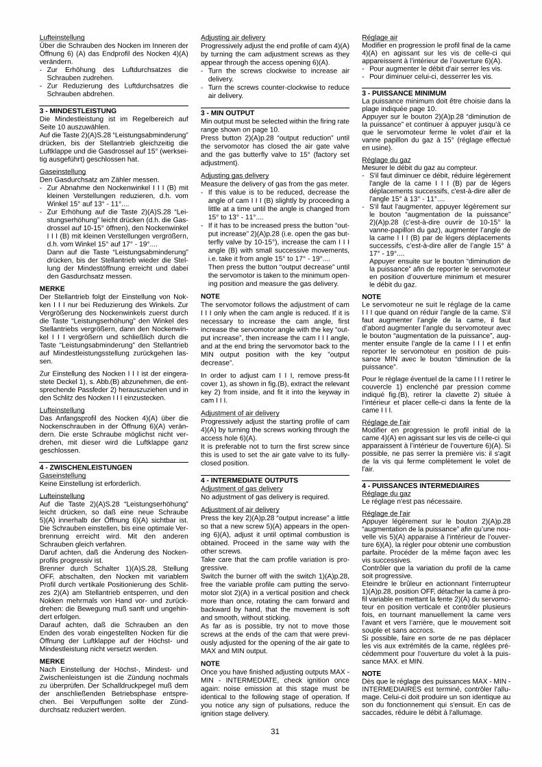
31
Adjusting air deliveryProgressively adjust the end profile of cam 4)(A)by turning the cam adjustment screws as theyappear through the access opening 6)(A).- Turn the screws clockwise to increase air
delivery.- Turn the screws counter-clockwise to reduce
air delivery.
3 - MIN OUTPUTMin output must be selected within the firing raterange shown on page 10.Press button 2)(A)p.28 “output reduction” untilthe servomotor has closed the air gate valveand the gas butterfly valve to 15° (factory setadjustment).
Adjusting gas deliveryMeasure the delivery of gas from the gas meter.- If this value is to be reduced, decrease the
angle of cam I I I (B) slightly by proceeding alittle at a time until the angle is changed from15° to 13° - 11°....
- If it has to be increased press the button “out-put increase” 2)(A)p.28 (i.e. open the gas but-terfly valve by 10-15°), increase the cam I I Iangle (B) with small successive movements,i.e. take it from angle 15° to 17° - 19°....Then press the button “output decrease” untilthe servomotor is taken to the minimum open-ing position and measure the gas delivery.
NOTEThe servomotor follows the adjustment of camI I I only when the cam angle is reduced. If it isnecessary to increase the cam angle, firstincrease the servomotor angle with the key “out-put increase”, then increase the cam I I I angle,and at the end bring the servomotor back to theMIN output position with the key ”outputdecrease”.
In order to adjust cam I I I, remove press-fitcover 1), as shown in fig.(B), extract the relevantkey 2) from inside, and fit it into the keyway incam I I I.
Adjustment of air deliveryProgressively adjust the starting profile of cam4)(A) by turning the screws working through theaccess hole 6)(A). It is preferable not to turn the first screw sincethis is used to set the air gate valve to its fully-closed position.
4 - INTERMEDIATE OUTPUTSAdjustment of gas deliveryNo adjustment of gas delivery is required.
Adjustment of air deliveryPress the key 2)(A)p.28 “output increase” a littleso that a new screw 5)(A) appears in the open-ing 6)(A), adjust it until optimal combustion isobtained. Proceed in the same way with theother screws.Take care that the cam profile variation is pro-gressive.Switch the burner off with the switch 1)(A)p.28,free the variable profile cam putting the servo-motor slot 2)(A) in a vertical position and checkmore than once, rotating the cam forward andbackward by hand, that the movement is softand smooth, without sticking.As far as is possible, try not to move thosescrews at the ends of the cam that were previ-ously adjusted for the opening of the air gate toMAX and MIN output.
NOTEOnce you have finished adjusting outputs MAX -MIN - INTERMEDIATE, check ignition onceagain: noise emission at this stage must beidentical to the following stage of operation. Ifyou notice any sign of pulsations, reduce theignition stage delivery.
Réglage airModifier en progression le profil final de la came4)(A) en agissant sur les vis de celle-ci quiappareissent à l’intérieur de l’ouverture 6)(A).- Pour augmenter le débit d'air serrer les vis.- Pour diminuer celui-ci, desserrer les vis.
3 - PUISSANCE MINIMUMLa puissance minimum doit être choisie dans laplage indiquée page 10.Appuyer sur le bouton 2)(A)p.28 “diminution dela puissance” et continuer à appuyer jusqu’à ceque le servomoteur ferme le volet d’air et lavanne papillon du gaz à 15° (réglage effectuéen usine).
Réglage du gazMesurer le débit du gaz au compteur.- S'il faut diminuer ce débit, réduire légèrement
l'angle de la came I I I (B) par de légersdéplacements successifs, c'est-à-dire aller del'angle 15° à 13° - 11°....
- S'il faut l'augmenter, appuyer légèrement surle bouton “augmentation de la puissance”2)(A)p.28 (c’est-à-dire ouvrir de 10-15° lavanne-papillon du gaz), augmenter l’angle dela came I I I (B) par de légers déplacementssuccessifs, c’est-à-dire aller de l’angle 15° à17° - 19°....Appuyer ensuite sur le bouton “diminution dela puissance” afin de reporter le servomoteuren position d’ouverture minimum et mesurerle débit du gaz.
NOTELe servomoteur ne suit le réglage de la cameI I I que quand on réduir l'angle de la came. S’ilfaut augmenter l’angle de la came, il fautd’abord augmenter l’angle du servomoteur avecle bouton “augmentation de la puissance”, aug-menter ensuite l’angle de la came I I I et enfinreporter le servomoteur en position de puis-sance MIN avec le bouton “diminution de lapuissance”.
Pour le réglage éventuel de la came I I I retirer lecouvercle 1) enclenché par pression commeindiqué fig.(B), retirer la clavette 2) située àl’intérieur et placer celle-ci dans la fente de lacame I I I.
Réglage de l'airModifier en progression le profil initial de lacame 4)(A) en agissant sur les vis de celle-ci quiapparaissent à l’intérieur de l’ouverture 6)(A). Sipossible, ne pas serrer la première vis: il s'agitde la vis qui ferme complètement le volet del'air.
4 - PUISSANCES INTERMEDIAIRESRéglage du gazLe réglage n'est pas nécessaire.
Réglage de l'airAppuyer légèrement sur le bouton 2)(A)p.28“augmentation de la puissance” afin qu’une nou-velle vis 5)(A) apparaise à l’intérieur de l’ouver-ture 6)(A), la régler pour obtenir une combustionparfaite. Procéder de la même façon avec lesvis successives.Contrôler que la variation du profil de la camesoit progressive.Eteindre le brûleur en actionnant l'interrupteur1)(A)p.28, position OFF, détacher la came à pro-fil variable en mettant la fente 2)(A) du servomo-teur en position verticale et contrôler plusieursfois, en tournant manuellement la came versl’avant et vers l’arrière, que le mouvement soitsouple et sans accrocs.Si possible, faire en sorte de ne pas déplacerles vis aux extrémités de la came, réglées pré-cédemment pour l'ouverture du volet à la puis-sance MAX. et MIN.
NOTEDès que le réglage des puissances MAX - MIN -INTERMEDIAIRES est terminé, contrôler l'allu-mage. Celui-ci doit produire un son identique auson du fonctionnement qui s'ensuit. En cas desaccades, réduire le débit à l'allumage.
LufteinstellungÜber die Schrauben des Nocken im Inneren derÖffnung 6) (A) das Endprofil des Nocken 4)(A)verändern.- Zur Erhöhung des Luftdurchsatzes die
Schrauben zudrehen.- Zur Reduzierung des Luftdurchsatzes die
Schrauben abdrehen.
3 - MINDESTLEISTUNGDie Mindestleistung ist im Regelbereich aufSeite 10 auszuwählen.Auf die Taste 2)(A)S.28 “Leistungsabminderung”drücken, bis der Stellantrieb gleichzeitig dieLuftklappe und die Gasdrossel auf 15° (werksei-tig ausgeführt) geschlossen hat.
GaseinstellungDen Gasdurchsatz am Zähler messen.- Zur Abnahme den Nockenwinkel I I I (B) mit
kleinen Verstellungen reduzieren, d.h. vomWinkel 15° auf 13° - 11°....
- Zur Erhöhung auf die Taste 2)(A)S.28 “Lei-stungserhöhung” leicht drücken (d.h. die Gas-drossel auf 10-15° öffnen), den NockenwinkelI I I (B) mit kleinen Verstellungen vergrößern,d.h. vom Winkel 15° auf 17° - 19°....Dann auf die Taste “Leistungsabminderung”drücken, bis der Stellantrieb wieder die Stel-lung der Mindestöffnung erreicht und dabeiden Gasdurchsatz messen.
MERKEDer Stellantrieb folgt der Einstellung von Nok-ken I I I nur bei Reduzierung des Winkels. ZurVergrößerung des Nockenwinkels zuerst durchdie Taste “Leistungserhöhung” den Winkel desStellantriebs vergrößern, dann den Nockenwin-kel I I I vergrößern und schließlich durch dieTaste “Leistungsabminderung” den Stellantriebauf Mindestleistungsstellung zurückgehen las-sen.
Zur Einstellung des Nocken I I I ist der eingera-stete Deckel 1), s. Abb.(B) abzunehmen, die ent-sprechende Passfeder 2) herauszuziehen und inden Schlitz des Nocken I I I einzustecken.
LufteinstellungDas Anfangsprofil des Nocken 4)(A) über dieNockenschrauben in der Öffnung 6)(A) verän-dern. Die erste Schraube möglichst nicht ver-drehen, mit dieser wird die Luftklappe ganzgeschlossen.
4 - ZWISCHENLEISTUNGENGaseinstellungKeine Einstellung ist erforderlich.
LufteinstellungAuf die Taste 2)(A)S.28 “Leistungserhöhung”leicht drücken, so daß eine neue Schraube5)(A) innerhalb der Öffnung 6)(A) sichtbar ist.Die Schrauben einstellen, bis eine optimale Ver-brennung erreicht wird. Mit den anderenSchrauben gleich verfahren.Daruf achten, daß die Änderung des Nocken-profils progressiv ist.Brenner durch Schalter 1)(A)S.28, StellungOFF, abschalten, den Nocken mit variablemProfil durch vertikale Positionierung des Schlit-zes 2)(A) am Stellantrieb entsperren, und denNokken mehrmals von Hand vor- und zurück-drehen: die Bewegung muß sanft und ungehin-dert erfolgen.Darauf achten, daß die Schrauben an denEnden des vorab eingestellten Nocken für dieÖffnung der Luftklappe auf der Höchst- undMindestleistung nicht versetzt werden.
MERKENach Einstellung der Höchst-, Mindest- undZwischenleistungen ist die Zündung nochmalszu überprüfen. Der Schalldruckpegel muß demder anschließenden Betriebsphase entspre-chen. Bei Verpuffungen sollte der Zünd-durchsatz reduziert werden.
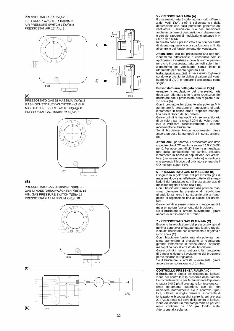
32
5 - PRESSOSTATO ARIA (A)Il pressostato aria è collegato in modo differen-ziale, vedi 1)(A), cioè è sollecitato sia dalladepressione che dalla pressione generate dalventilatore. Il bruciatore può così funzionareanche in camere di combustione in depressionee con altri rapporti di modulazione: potenze MIN/ MAX fino a 1/6.In questo caso il pressostato aria non necessitadi alcuna regolazione e la sua funzione si limitaal controllo del funzionamento del ventilatore.
Attenzione: l'uso del pressostato aria con fun-zionamento differenziale è consentito solo inapplicazioni industriali e dove le norme permet-tono che il pressostato aria controlli solo il fun-zionamento del ventilatore, senza limite diriferimento per quanto riguarda il CO.Nelle applicazioni civili è necessario togliere ilcondotto proveniente dall’aspirazione del venti-latore, vedi 2)(A), e regolare il pressostato comesegue.
Pressostato aria collegato come in 2)(A):eseguire la regolazione del pressostato ariadopo aver effettuato tutte le altre regolazioni delbruciatore con il pressostato aria regolato a ini-zio scala (A).Con il bruciatore funzionante alla potenza MINaumentare la pressione di regolazione girandolentamente in senso orario l’apposita manopo-lina fino al blocco del bruciatore.Girare quindi la manopolina in senso antiorariodi un valore pari a circa il 20% del valore rego-lato e verificare successivamente il correttoavviamento del bruciatore.Se il bruciatore blocca nuovamente, girareancora un poco la manopolina in senso antiora-rio.
Attenzione : per norma, il pressostato aria deveimpedire che il CO nei fumi superi l' 1% (10.000ppm). Per accertarsi di ciò, inserire un analizza-tore della combustione nel camino, chiuderelentamente la bocca di aspirazione del ventila-tore (per esempio con un cartone) e verificareche avvenga il blocco del bruciatore prima che ilCO nei fumi superi l'1%.
6 - PRESSOSTATO GAS DI MASSIMA (B)Eseguire la regolazione del pressostato gas dimassima dopo aver effettuato tutte le altre rego-lazioni del bruciatore con il pressostato gas dimassima regolato a fine scala (B).Con il bruciatore funzionante alla potenza mas-sima, diminuire la pressione di regolazionegirando lentamente in senso antiorario la mano-polina di regolazione fino al blocco del brucia-tore.Girare quindi in senso orario la manopolina di 2mbar e ripetere l'avviamento del bruciatore.Se il bruciatore si arresta nuovamente, girareancora in senso orario di 1 mbar.
7 - PRESSOSTATO GAS DI MINIMA (C)Eseguire la regolazione del pressostato gas diminima dopo aver effettuato tutte le altre regola-zioni del bruciatore con il pressostato regolato ainizio scala (C).Con il bruciatore funzionante alla potenza mas-sima, aumentare la pressione di regolazionegirando lentamente in senso orario l'appositamanopolina fino all'arresto del bruciatore.Girare quindi in senso antiorario la manopolinadi 2 mbar e ripetere l'avviamento del bruciatoreper verificarne la regolarità.Se il bruciatore si arresta nuovamente, girareancora in senso antiorario di 1 mbar.
CONTROLLO PRESENZA FIAMMA (C)Il bruciatore è dotato del sistema ad ionizza-zione per controllare la presenza della fiamma.La corrente minima per far funzionare l'apparec-chiatura è di 6 µA. Il bruciatore fornisce una cor-rente nettamente superiore, tale da nonrichiedere normalmente alcun controllo. Qua-lora, tuttavia, si voglia misurare la corrente diionizzazione bisogna disinserire la spina-presa27)(A)p.8 posta sul cavo della sonda di ionizza-zione ed inserire un microamperometro per cor-rente continua da 100 µA fondo scala.Attenzione alla polarità.
(A)
(C)
(D)
PRESSOSTATO ARIA 15)(A)p. 8LUFT-DRUCKWÄCHTER 15)(A)S. 8AIR PRESSURE SWITCH 15)(A)p. 8PRESSOSTAT AIR 15)(A)p. 8
PRESSOSTATO GAS DI MASSIMA 4)(A)p. 8GAS-HÖCHSTDRUCKWÄCHTER 4)(A)S. 8MAX. GAS PRESSURE SWITCH 4)(A)p. 8PRESSOSTAT GAZ MAXIMUM 4)(A)p. 8
PRESSOSTATO GAS DI MINIMA 7)(B)p. 18GAS-MINDESTDRUCKWÄCHTER 7)(B)S. 18MIN. GAS PRESSURE SWITCH 7)(B)p. 18PRESSOSTAT GAZ MINIMUM 7)(B)p. 18
(B)
1)
2)
LFL
24
D521
D794
D66
D896
D795

33
5 - LUFTDRUCKWÄCHTER (A)Der Luft-Druckwächter (Differentialtyp) wirddurch den Unterdruck und den Druck desGebläses beansprucht, siehe 1)(A).Der Brenner kann daher auch in Brennkammernmit Unterdruck und hohen Modulationsverhält-nissen funktionieren: Mindest - Höchstleistungbis 1/6.In diesem Fall benötigt der Luft-Druckwächterkeine einstellung und seine Funktion ist auf diekontrolle des Gebläsebetriebs beschränkt.
Achtung: der Gebrauch des Luftdruckwächtersals Differentialschalter ist nur für Industriean-wendungen zugelassen. Er ist auch dort zuge-lassen, wo laut Vorschriften derLuftdruckwächter nur den Gebläsebetrieb, ohneBezug auf CO-Grenzen, überwacht.Bei Zivilanwendungen muß man die Gebläsean-saugleitung, siehe 2)(A), abnehmen und denDruckwächter wie folgt einstellen.
Luft-Druckwächter wie in 2)(A) verbunden:die Einstellung des Luftdruckwächters erfolgtnach allen anderen Brenner-Regulierungen; derDruckwächter wird auf Skalenbeginn (A) einge-stellt.Bei Brennerbetrieb auf Mindestleistung den Ein-stelldruck durch Drehen des dafür bestimmtenDrehknopfs im Uhrzeigersinn langsam erhöhenbis eine Störabschaltung erfolgt.Dann den Drehknopf gegen den Uhrzeigersinnum etwa 20% des eingestellten Druckwerteszurückdrehen und den Brenner wieder anfah-ren, um zu überprüfen, ob dieser ordnungsge-mäß arbeitet.Sollte eine Störabschaltung eintreten, den Dreh-knopf ein bißchen wieder noch zurückdrehen.
Achtung: als Regel gilt, daß der Luftdruck-wächter verhindern muß, daß das CO im Abgas1% (10.000 ppm) überschreitet.Um das sicherzustellen, einen Verbrennungs-analysator in den Kamin einfügen, die Ansaug-öffnung des Gebläses langsam schließen (zumBeispiel mit Pappe) und prüfen, daß die Störab-schaltung des Brenners erfolgt, bevor das CO inden Abgasen 1% überschreitet.
6 - GAS-HÖCHSTDRUCKWÄCHTER (B)Die Einstellung des Gas-Höchstdruckwächterserfolgt nach allen anderen Brennereinstellun-gen, wobei der Wächter auf Skalenende (B) ein-gestellt wird.Bei Brennerbetrieb auf Höchstleistung den Ein-stelldruck durch langsames Drehen des Dreh-knopfs gegen den Uhrzeigersinn vermindern,bis eine Störabschaltung erfolgt.Darauf den Drehknopf im Uhrzeigersinn um 2mbar vordrehen und den Brenner wieder anfah-ren. Falls eine Störabschaltung eintreten sollte,im Uhrzeigersinn noch um 1 mbar vordrehen.
7 - GAS-MINIMALDRUCKWÄCHTER (C)Die Einstellung des Gas-Minimaldruckwächterserfolgt nach allen anderen Brennereinstellun-gen, wobei der Wächter auf Skalenbeginn (C)eingestellt wird.Bei Brennerbetrieb auf Höchstleistung den Ein-stelldruck durch langsam Drehen des dafürbestimmten Drehknopfs im Uhrzeigersinn lan-sam erhöhen, bis der Brenner ausschaltet.Dann den Drehknopf gegen den Uhrzeigersinnum 2 mbar zurückdrehen und den Brenner wie-der anfahren, um zu überprüfen, ob dieser ord-nungsgemäß arbeitet. Sollte der Brenner wiederausschalten, den Drehknopf noch einmal gegenden Uhrzeigersinn um 1 mbar drehen.
FLAMMENÜBERWACHUNG (D)Der Brenner ist mit einem Ionisationsgerät zurFlammenüberwachung ausgerüstet. Der erfor-derliche Mindeststrom beträgt 6 µA. Da derBrenner einen weitaus höheren Strom erreicht,sind normalerweise keine Kontrollen nötig. Willman den Ionisationsstrom messen, muß derSteckanschluß 27)(A)S.8 am Kabel der Ionisati-onssonde ausgeschaltet und ein Gleichstrom-Mikroamperemeter, Meßbereich 100 µA, einge-schaltet werden. Auf richtige Polung achten!
5 - AIR PRESSURE SWITCH (A)The air pressure switch is differentially con-nected, see 1)(A), it is activated by both the neg-ative pressure and the general pressure fromthe fan.In this way the burner can operate even in nega-tive pressure combustion chambers and withhigh modulation ratios: MIN / MAX outputs of upto 1/6.In this case the air pressure switch needs noadjustment and its function is limited to control-ling fan operation.
Attention: the use of the air pressure switchwith differential operation is allowed only inindustrial applications and where rules enablethe air pressure switch to control only fan opera-tion without any reference to CO limit.In civil applications the pipe from the fan air inletshould be removed, see 2)(A) and adjust thepressure switch as follows.
Air pressure switch connected as 2)(A):adjust the air pressure switch after having per-formed all other burner adjustments with the airpressure switch set to the start of the scale (A).With the burner operating at min. output,increase adjustment pressure by slowly turningthe relative knob clockwise until the burner locksout.Then turn the knob anti-clockwise by about 20%of the set point and repeat burner starting toensure it is correct.If the burner locks out again, turn the knob anti-clockvise a little bit more.
Attention: as a rule, the air pressure switchmust limit the CO in the fumes to less than 1%(10,000 ppm).To check this, insert a combustion analyser intothe chimney, slowly close the fan suction inlet(for example with cardboard) and check that theburner locks out, before the CO in the fumesexceeds 1%.
6 - MAXIMUM GAS PRESSURE SWITCH (B)Adjust the maximum gas pressure switch afterhaving performed all other burner adjustmentswith the maximum gas pressure switch set tothe end of the scale (B).With the burner operating at MAX output,reduce the adjustment pressure by slowly turn-ing the adjustment knob anticlockwise until theburner locks out.Then turn the knob clockwise by 2 mbar andrepeat burner firing.If the burner locks out again, turn the knob againclockwise by 1 mbar.
7 - MINIMUM GAS PRESSURE SWITCH (C)Adjust the minimum gas pressure switch afterhaving performed all the other burner adjust-ments with the pressure switch set at the start ofthe scale (C).With the burner operating at MAX output,increase adjustment pressure by slowly turningthe relative knob clockwise until the burner locksout.Then turn the knob anti-clockwise by 2 mbarand repeat burner starting to ensure it is uni-form.If the burner locks out again, turn the knob anti-clockwise again by 1 mbar.
FLAME PRESENT CHECK (C)The burner is fitted with an ionisation systemwhich ensures that a flame is present. The mini-mum current for plant operation is 6 µA. Theburner provides a much higher current, so thatcontrols are not normally required. However, if itis necessary to measure the ionisation current,disconnect the plug-socket 27)(A)p.8 on the ion-isation probe cable and insert a direct currentmicroamperometer with a base scale of 100 µA.Carefully check polarities.
5 - PRESSOSTAT DE L'AIR (A)Le pressostat de l’air est relié de façon différen-tielle, voir 1)(A), c’est-à-dire qu’il est sollicitéaussi bien par la dépression que par la pressionproduites par le ventilateur.De cette façon, le brûleur peut fonctionner éga-lement dans la chambre de combustion endépression et avec des rapports élevés demodulation: puissances MIN / MAX jusqu’à 1/6.Dans ce cas, le pressostat de l’air ne nécessited’aucun réglage et sa fonction se limite au con-trôle du fonctionnement du ventilateur.
Attention: on ne peut utiliser le pressostat del'air à fonctionnement différentiel que dans desapplications industrielles et quand les normespermettent que le pressostat de l'air ne contrôleque le fonctionnement du ventilateur, sans limitde référence pour le CO.Dans les applications civiles il faut enlever leconduit provenant de l’aspiration du ventilateur,voir 2)(A), et régler le pressostat comme suit.
Pressostat de l’air relié comme sur la fig. 2)(A):effectuer le réglage du pressostat de l’air aprèsavoir effectué tous les autres réglages du brû-leur avec le pressostat de l’air réglé en débutd’échelle (A).Lorsque le brûleur fonctionne à la puissanceMIN, augmenter la pression de réglage en tour-nant lentement dans le sens des aiguilles d’unemontre la petite molette prévue à cet effetjusqu’au blocage du brûleur. Tourner ensuitedans le sens contraire la petite molette du 20%du valeur reglé et répéter le démarrage du brû-leur pour en vérifier la régularité. Si le brûleur sebloque à nouveau, tourner encore un peu lapetite molette dans le sens contraire auxaiguilles d’une montre.
Attention: comme le veut la norme, le pressos-tat de l'air doit empêcher que le CO dans lesfumées dépasse 1% (10.000 ppm). Pour s'en rendre compte, placer un analyseurde combustion dans le conduit, fermer lente-ment la bouche d'aspiration du ventilateur (parexemple avec un carton) et vérifier qu'il y ait blo-cage du brûleur, avant que le CO dans lesfumées ne dépasse 1%.
6 - PRESSOSTAT GAZ SEUIL MINIMUM (B)Effectuer le réglage du pressostat gaz maxi-mum après avoir effectué tous les autres régla-ges du brûleur avec le pressostat gaz maximumréglé en fin d'échelle (B).Avec le brûleur fonctionnant à la puissanceMAX, diminuer la pression de réglage en tour-nant lentement dans le sens contraire auxaiguilles d'une montre la petite molette deréglage jusqu’au blocage du brûleur.Tourner ensuite dans le sens des aiguilles d’unemontre la petite molette de 2 mbar et répéter ledémarrage du brûleur. Si le brûleur se bloque ànouveau, tourner encore dans le sens desaiguilles d'une montre de 1 mbar.
7 - PRESSOSTAT GAZ SEUIL MINIMUM (C)Effectuer le réglage du pressostat gaz seuilminimum après avoir effectué tous les autresréglages du brûleur avec le pressostat réglé endébut d'échelle (C).Lorsque le brûleur fonctionne à la puissanceMAX, augmenter la pression de réglage en tour-nant lentement dans le sens des aiguilles d'unemontre la petite molette prévue à cet effetjusqu'à l'arrêt du brûleur. Tourner ensuite dansle sens contraire la petite molette de 2 mbar etrépéter le démarrage du brûleur pour en vérifierla régularité. Si le brûleur s' arrête à nouveau,tourner encore dans le sens inverse auxaiguilles d'une montre de 1 mbar.
CONTROLE PRESENCE FLAMME (C)Le brûleur est muni d'un système à ionisationpour contrôler la présence de la flamme. Pourfaire fonctionner le boîtier de contrôle le courantminimum est de 6 µA. Le brûleur produit un cou-rant nettement supérieur qui ne nécessite nor-malement d'aucun contrôle. Toutefois, si on veutmesurer le courant d'ionisation, il fautdéconnecter la fiche-prise 27)(A)p.8 placée surle câble de la sonde d'ionisation et connecter unmicroampèremètre pour courant continu de 100µA bas d'échelle. Attention à la polarité.

34
FUNZIONAMENTO BRUCIATORE
AVVIAMENTO BRUCIATORE (A)• 0s: Chiusura telecomando TL.
Avvio motore ventilatore.• 6s: Avvio servomotore:
ruota verso destra di 90°, cioè finoall'intervento del contatto sulla cammaI (E)p. 26.La serranda aria si posiziona sullapotenza MAX.
• 30s: Fase di preventilazione con la portatad'aria della potenza MAX. Durata 31 secondi.
• 61s: Il servomotore ruota verso sinistra finoall'angolo impostato sulla camma I I I(E)p. 26 per la potenza MIN.
• 81s: La serranda dell'aria e la farfalla delgas si posizionano sulla potenza MIN;con camma I I I)(E)p.26 a 15°.
• 84s: Scocca la scintilla dall’elettrodod’accensione.
• 90s: Si aprono la valvola di sicurezza VS ela valvola di regolazione VR (aperturarapida). Si accende la fiamma ad unapiccola potenza, punto A.Segue un progressivo aumento dellapotenza, apertura lenta della valvolaVR, fino alla potenza MIN, punto B.
• 93s: Si spegne la scintilla.• 114s: Termina il ciclo di avviamento
dell’apparecchiatura elettrica.
FUNZIONAMENTO A REGIME (A)Bruciatore senza il regolatore di potenzaRWF40 Terminato il ciclo di avviamento, il comando delservomotore passa al telecomando TR che con-trolla la pressione o la temperatura in caldaia,punto C. (L'apparecchiatura elettrica continuacomunque a controllare la presenza dellafiamma e la corretta posizione dei pressostatiaria e gas di massima).• Se la temperatura o la pressione è bassa per
cui il telecomando TR è chiuso, il bruciatoreaumenta progressivamente la potenza fino alvalore MAX (tratto C-D).
• Se poi la temperatura o la pressione aumentafino all’apertura di TR, il bruciatore diminuisceprogressivamente la potenza fino al valoreMIN, (tratto E-F). E così via.
• L'arresto del bruciatore avviene quando larichiesta di calore è minore di quella fornitadal bruciatore alla potenza MIN, (tratto G-H).Il telecomando TL si apre, il servomotoreritorna all'angolo 0° limitato dal contatto dallacamma I I (E)p.26. La serranda si chiudecompletamente per ridurre al minimo ledispersioni termiche.
Ad ogni cambio di potenza, il servomotore prov-vede automaticamente a modicare la portatadel gas (valvola a farfalla) e la portata dell’aria(serranda ventilatore).Bruciatore con il regolatore di potenzaRWF40Vedere il manuale che accompagna il regola-tore.
MANCATA ACCENSIONE (B)Se il bruciatore non si accende si ha il bloccoentro 3 s dall'apertura della valvola gas e 93 sdalla chiusura di TL.
SPEGNIMENTO DEL BRUCIATORE IN FUN-ZIONAMENTO Se la fiamma si spegne in funzionamento si ha ilblocco del bruciatore entro 1s.
(A)
(B)
ACCENSIONE REGOLARE ORDNUNGSGEMÄSSES(n° = secondi dall’istante 0) (n° = Sekunden ab Zeitpunkt 0)
NORMAL FIRING ALLUMAGE REGULIER(n° = seconds from istant 0) (n° = secondes à partir de l’istant 0)
MANCATA ACCENSIONE / NICHTZÜNDEN
NO FIRING / LE BRULEUR NE S’ALLUME PAS
D798
D799

35
BURNER OPERATION
BURNER STARTING (A)• 0s: Load control TL closes.
Fan motor starts.• 6s: Servomotor starts:
90° rotation to right, until contact ismade on cam I (E)p.26.The air gate valve is positioned toMAX. output.
• 30s: Pre-purge stage with air delivery atMAX. output. Duration 31 seconds.
• 61s: Servomotor rotates to left up to theangle set on cam I I I (E)p.26 for MIN.output.
• 81s: The air gate valve and the gas butter-fly are positioned to MIN. output withcam I I I(E)p.26 at 15°.
• 84s: Ignition electrode strikes a spark.• 90s: Safety valve VS and adjustment valve
VR (rapid opening) open. The flame isignited at a low output level, point A.Delivery is then progressivelyincreased, with the valve VR openingslowly up to MIN. output, point B.
• 93s: The spark goes out.• 114s: The control box starting cycle ends.
STEADY STATE OPERATION (A)Burner without outputregulator RWF40 At the end of the starting cycle, the servomotorcontrol then passes to the load control TR forboiler pressure or temperature, point C.(The LFL control box continues, however, tocheck that the flame is present and that the airand gas max. pressure switches are in the cor-rect position.)• If the temperature or pressure is low (and the
TR load control is consequently closed), theburner progressively increases its output tothe MAX. value, (section C-D).
• If subsequently the temperature or pressureincreases until TR opens, the burner progres-sively decreases its output to the MIN. value(section E-F).And so on.
• The burner locks out when demand for heat isless than the heat supplied by the burner atmin. output, (section G-H). Load control TL opens. The servomotorreturns to the 0° angle limited by contact withcam I I (E)p.26. The gate valve closes com-pletely to reduce thermal dispersion to a mini-mum.
Every time output is changed, the servomotorautomatically modifies gas delivery (gas butter-fly valve) and air delivery (fan gate valve).Burner with output regulator RWF40See the handbook enclosed with the regulator.
FIRING FAILURE (B)If the burner does not fire, it goes into lock-outwithin 3 s of the opening of the gas solenoidvalve and 93 s after the closing of control deviceTL.The control box pilot light will light up.
BURNER FLAME GOES OUT DURING OPER-ATION If the flame should accidentally go out duringoperation, the burner will lock out within 1s.
FONCTIONNEMENT BRULEUR
DEMARRAGE BRULEUR (A)• 0s: Fermeture télécommande TL.
Démarrage moteur ventilateur.• 6s: Démarrage servomoteur:
il tourne vers la droite de 90°, c’est àdire jusqu'à l'intervention du contactsur la came I (E)p.26. Le volet d'air sepositionne sur la puissance MAX.
• 30s: Phase de préventilation avec le débitd'air à la puissance MAX. Durée 31 secondes.
• 61s: Le servomoteur tourne vers la gauchejusqu'à l'angle réglé sur la came I I I(E)p.26 pour la puissance MIN.
• 81s: Le volet d'air et la vanne papillon dugaz se positionnent sur la puissanceMIN avec came I I I(E)p. 26 a 15°.
• 84s: L'étincelle jaillit de l'électrode d'allu-mage.
• 90s: La vanne de sécurité VS et la vannede réglage VR, ouverture rapide,s'ouvrent; la flamme s'allume à unepetite puissance, point A.On a ensuite une augmentation pro-gressive du débit, ouverture lente dela vanne de réglage VR, jusqu'à lapuissance MIN, point B.
• 93s: L'étincelle s'éteint.• 114s: Le cycle de démarrage du boîtier de
contrôle, point C, s'achève.
FONCTIONNEMENT DE REGIME (A)Brûleur sans régulateur de puissanceRWF40 Une fois le cycle de mise en marche terminé, lacommande du servomoteur passe à latélécommande TR qui contrôle la pression ou latempérature dans la chaudière, point C.(Le boîtier de contrôle LFL continue cependantà contrôler la présence de la flamme et la bonneposition des pressostats air et gaz maximum.)• Si la température ou la pression sont basses
et que par conséquent la télécommande TRest fermée, le brûleur augmente progressive-ment la puissance jusqu’à la valeur MAX,(segment C-D).
• Si la température ou la pression augmententensuite jusqu’à l’ouverture de TR, le brûleurréduit progressivement la puissance jusqu’àla valeur MIN, (segment E-F).Et ainsi de suite.
• L'arrêt du brûleur a lieu lorsque la demandede chaleur est inférieure à celle qui est four-nie par le brûleur à la puissance MIN, (seg-ment G-H). La télécommande TL s'ouvre, le servomoteurretourne à l'angle 0° limité par le contact de lacame I I (E)p.26. Le volet se ferme complète-ment pour réduire au minimum les disper-sions de chaleur.
A chaque changement de puissance, le servo-moteur modifie automatiquement le débit du gaz(vanne papillon) et le débit de l’air (volet du ven-tilateur).Brûleur avec le régulateur de puissance RWF40Voir le manuel fourni avec le régulateur.
ABSENCE D'ALLUMAGE (B)Si le brûleur ne s'allume pas, on a le blocagedans un délai de 3 s à partir de l'ouverture de lavanne gaz et de 93 s après la fermeture de TL.
EXTINCTION BRULEUR EN FONCTIONNE-MENT Si la flamme s'éteint accidentellement en coursde fonctionnement, le brûleur se bloque en 1seconde.
BRENNERBETRIEB
ANFAHREN DES BRENNERS (A)• 0s: Abschalten Fernsteuerung TL.
Anfahren Gebläsemotor.• 6s: Anfahren Stellmotor:
dreht um 90° nach rechts, d.h. heißt biszum Eingriff des Schaltstücks am Nok-ken I (E)S.26.Die Luftklappe positioniert sich aufHöchstleistung.
• 30s: Vorbelüftungsphase bei Luftdurchsatzwie bei Höchstleistung.Dauer 31 Sekunden.
• 61s: Der Stellmotor dreht nach links, biszum am Nocken I I I (D)S.26 eingestell-ten Winkel, für die Mindestleistung.
• 81s: Die Luftklappe und die Gasdrosselpositionieren sich auf Mindestleistung;mit Nocken I I I (E)S.26 auf 15°.
• 84s: Funkenbildung an der Zün-dungselektrode.
• 90s: Das Sicherheitsmagnetventil VS unddas Regelventil VR (schnellöffnend)öffnen sich und es erfolgt eine Flam-menbildung mit niedriger Leistung,Punkt A.Es erfolgt eine progressive Steigerungdes Durchsatzes, mit langsamer Öff-nung des Ventils VR bis zur Mindest-leistung, Punkt B.
• 93s: Der Funke erlischt.• 114s: Die Anlaufphase des Steuergeräts ist
beendet.
BETRIEBLEISTUNG (A)Brenner ohne den Leistungsregler RWF40 Nach dem Anfahrzyklus geht die Steuerung desStellantriebs an die Regelung TR über, die denDruck oder die Temperatur des Kessels über-wacht, Punkt C. (Das Steuergerät überwachtweiterhin die Flamme und die richtige Stellungder Luft- und Gas- Höchstdruckwächter.)• Wenn die Temperatur oder der Druck niedrig
und die Fernsteuerung TR geschlossen ist,steigert der Brenner die Leistung stufenweisebis zur Höchstleistung, (Strecke C-D).
• Wenn die Temperatur oder der Druck dannbis zur Öffnung von TR steigt, senkt der Bren-ner die Leistung stufenweise bis zur Mindest-leistung, (Strecke E-F), u.s.w.
• Der Brenner schaltet sich auf, wenn der Wär-mebedarf geringer ist, als die vom Brennerauf Mindestleistung gelieferte Wärme(Strecke G-H). Die Fernsteuerung TL öffnetsich, der Stellmotor geht auf den vom Nok-kenschaltstück I I)(E)S.26 begrenzten 0° Win-kel zurück. Die Klappe schließt ganz undbeschränkt den Wärmeverlust auf ein Mini-mum.
Bei jeder Leistungsumschaltung ändert derStellmotor automatisch den Gasdurchsatz (Gas-drossel) und den Luftdurchsatz (Gebläse-klappe).Brenner mit dem Leistungsregler RWF40Siehe das dem Leistungsregler beigefugteHandbuch.
MANGELNDE ZÜNDUNG (B)Wenn der Brenner nicht zündet, erfolgt eineStörabschaltung innerhalb von 3 s ab dem Öff-nen des Gasventils und 93 s nach der Verschlußdes TL.
ABSCHALTUNG WÄHREND DES BRENNER-BETRIEBS Erlischt die Flamme zufällig während des Bren-nerbetriebs, erfolgt nach 1 s die Störabschal-tung des Brenners.

36
CONTROLLI FINALI (con bruciatore funzio-nante)• Scollegare un filo del pressostato gas di
minima: • Aprire il telecomando TL:• Aprire il telecomando TS:il bruciatore deve fermarsi
• Scollegare il filo comune P del pressostatogas di massima:
• Scollegare il filo comune P del pressostatoaria:
• Scollegare il filo della sonda di ionizzazione: il bruciatore deve fermarsi in blocco
• Controllare che i bloccaggi meccanici deidispositivi di regolazione siano ben serrati.
MANUTENZIONE
CombustioneEffettuare l'analisi dei gas di scarico della com-bustione. Gli scostamenti significativi rispetto alprecedente controllo indicheranno i punti dovepiù attenta dovrà essere l'operazione di manu-tenzione.Fughe di gasControllare che non vi siano fughe di gas sulcondotto contatore-bruciatore.Filtro del gasSostituire il filtro del gas quando è sporco.Visore fiammaPulire il vetrino del visore fiamma (A).Testa di combustioneAprire il bruciatore e verificare che tutte le partidella testa di combustione siano integre, nondeformate dall'alta temperatura, prive di impu-rità provenienti dall'ambiente e correttamenteposizionate. In caso di dubbio, smontare ilgomito 7)(B).ServomotoreSvincolare la camma 4)(A)p.30, ruotando di 90°l’intaglio 2)(A) e controllare manualmente che lasua rotazione, avanti ed indietro, sia scorrevole.Vincolare nuovamente la camma 4).BruciatoreControllare che non vi siano usure anomale oviti allentate nei cinematismi che comandano laserranda aria e la farfalla del gas. Così purebloccate devono essere le viti che fissano i cavinella morsettiera del bruciatore.Pulire esternamente il bruciatore, particolar-mente gli snodi e la camma 4)(A)p.30. CombustioneRegolare il bruciatore se i valori della combu-stione trovati all'inizio dell'intervento non soddi-sfano le Norme vigenti o, comunque, noncorrispondono ad una buona combustione.Scrivere in una apposita scheda i nuovi valoridella combustione, saranno utili per i successivicontrolli.
PER APRIRE IL BRUCIATORE (B):- togliere tensione.- Togliere la 4 vite 1) ed estrarre il cofano 2).- Sganciare lo snodo 3) dal settore graduato 4).- Togliere la vite 5) e la copiglia 9) ed arretrare
il bruciatore sulle guide 6) per circa 100 mm.Disinserire i cavi di sonda ed elettrodo equindi arretrare del tutto il bruciatore.
- Ruotarlo come in figura ed infilare nel foro diuna delle due guide la copiglia 9) in modo cheil bruciatore rimanga in quella posizione.
A questo punto è possibile estrarre il distributoredel gas 7) dopo aver tolto la vite 8).
PER CHIUDERE IL BRUCIATORE (B):- Togliere la copiglia 9) e spingere il bruciatore
fino a circa 100 mm dal manicotto. - Reinserire i cavi e far scorrere il bruciatore
fino a battuta. - Rimettere la vite 5) e la copiglia 9) e tirare
delicatamente verso l'esterno i cavi di sondaed elettrodo, fino a metterli in leggera ten-sione.
- Riagganciare lo snodo 3) al settore graduato4).
(A)
(B)
VISORE FIAMMASICHTFENSTER FLAMMEFLAME INSPECTION WINDOWVISEUR FLAMME
APERTURA BRUCIATOREBRENNERÖFFNUNGOPENING THE BURNEROUVERTURE BRULEUR
D484
D800
37
ENDKONTROLLEN (bei Brenner in Betrieb)• Einen Draht des Gas-Mindestdruckwächters
abtrennen: • Fernsteuerung TL öffnen:• Fernsteuerung TS öffnen:der Brenner muß anhalten
• Gemeinsamen Draht P des Gas-Höchstdruckwächters abtrennen:
• Gemeinsamen Draht P des Luft-Druckwäch-ters abtrennen:
• Draht der Ionisationssonde abtrennen: der Brenner muß in Störabschaltung anhalten
• Überprüfen, ob die mechamischen Sperrender Einstellvorrichtungen richtig klemmen.
WARTUNG
VerbrennungDie Abgase der Verbrennung analysieren.Bemerkenswerte Abweichungen im Vergleichzur vorherigen Überprüfung zeigen die Stellean, wo die Wartung aufmerksamer ausgeführtwerden soll.GasundichtigkeitenDie Zähler-Brenner-Leistung auf Gasundichtig-keiten kontrollieren.GasfilterVerschmutzten Gasfilter austauschen.FlammensichtfensterDas Sichtfenster (A) putzen.FlammkopfDen Brenner öffnen und überprüfen, ob alleFlammkopfteile unversehrt, nicht durch hoheTemperatur verformt, ohne Schmutzteile aus derUmgebung und richtig positioniert sind. ImZweifelsfall den Schlitten 7)(B) ausbauen.StellantriebDen Nocken 4)(A)S.30 durch 90° Drehung desSchlitzes 2)(A) vom Stellantrieb entsperren, undvon Hand die ungehinderte Drehbewegung vorund zurück nachweisen. Den Nocken 4)(A) wieder sperren.BrennerEs ist zu überprüfen, ob ungewöhnlicher Ver-schleiß oder die Lockerung der Schrauben inden Antriebselementen der Luftklappe und Gas-drossel vorliegen. Die Schrauben zur Befesti-gung der Kabel an das Klemmenbrett desBrenners müssen ebenfalls festgezogen sein.Den Brenner, und besonders die Gelenke undden Nocken 4)(A)S.30, von außen reinigen. VerbrennungFalls die anfänglich festgestellten Verbren-nungswerte nicht mit den geltenden Vorschriftenübereinstimmen, oder jedenfalls nicht einer kor-rekten Verbrennung entsprechen, muß derBrenner neu eingestellt werden.Tragen Sie auf einem geeigneten Formular dieneuen Verbrennungswerte ein, die für spätereKontrollen nützlich sind.
ÖFFNUNG DES BRENNERS (B):- spannung unterbrechen.- Die Schraube 1) herausdrehen und die Bren-
nerverkleidung 2) abnehmen.- Gelenk 3) aus dem Skalensegment 4) aus-
hängen.- Die Schraube 5) und den Splint 9) abnehmen
und den Brenner auf den Führungen 6) ca.100 mm nach hinten versetzen. Die Sonden-und Elektrodenkabel abtrennen und anschlie-ßen den Brenner ganz nach hinten versetzen.
- Den Brenner wie in Abb. drehen, den Splint 9)in die Bohrung einer zwei Führungen so hin-einstecken, daß der Brenner in jener Stellungbleibt.
Nun kann der Gasverteiler 7) nach Entnahmevon Schraube 8) herausgezogen werden.
SCHLIEßEN DES BRENNERS (B): - Den Splint 9) abnehmen und den Brenner auf
eine Abstand von ca. 100 mm zur Muffe vor-schieben.
- Die Kabel einsetzen und den Brenner bis zumAnschlag einschieben.
- Die Schraube 5) und den Splint 9) wieder ein-setzen und die Sonden- und Elektrodenkabelbehutsam nach außen ziehen, bis sie leichtangespannt sind.
- Gelenk 3) wieder an Skalensegment 4) ein-hängen.
FINAL CHECKS (with burner running)• Disconnect one of the wires on the minimum
gas pressure switch: • Open remote control device TL:• Open remote control device TS:the burner must stop
• Disconnect the common wire P from the max-imum gas pressure switch:
• Disconnect the common wire P from the airpressure switch:
• Disconnect the ionisation probe lead: the burner must lock out
• Make sure that the mechanical locking sys-tems on the various adjustment devices arefully tightened.
MAINTENANCE
CombustionThe optimum calibration of the burner requiresan analysis of the flue gases. Significant differ-ences with respect to the previous measure-ments indicate the points where more careshould be exercised during maintenance.Gas leaksMake sure that there are no gas leaks on thepipework between the gas meter and theburner.Gas filterChange the gas filter when it is dirty.Flame inspection windowClean the flame inspection window (A).Combustion headOpen the burner and make sure that all compo-nents of the combustion head are in good condi-tion, not deformed by the high temperatures,free of impurities from the surroundings and cor-rectly positioned. If in doubt, disassemble theelbow fitting 7)(B).ServomotorDisengage the cam 4)(A)p.30 from servomotor,by turning slot 2)(A) through 90° and turn itbackward and forward by hand to make sure it isfree moving. Now engage cam 4)(A) again.BurnerCheck for excess wear or loose screws in themechanisms controlling the air gate valve andthe gas butterfly valve. Also make sure that thescrews securing the electrical leads in theburner connections are fully tightened. Clean the outside of the burner, taking specialcare with the transmission joints and cam4)(A)p.30.CombustionAdjust the burner if the combustion values foundat the beginning of the operation do not complywith the regulations in force, or at any rate, donot correspond to good combustion. Use theappropriate card to record the new combustionvalues; they will be useful for subsequent con-trols.
TO OPEN THE BURNER (B):- switch off the electrical power.- Remove screw 1) and withdraw cover 2).- Disengage the articulated coupling 3) from
the graduated sector 4).- Remove screw 5), and the split pin 9) and pull
the burner by about 100 mm on the slide bars6). Disconnect the probe and electrode leadsand then pull the burner fully back.
- Turn the burner as shown in the figure and fitthe splint pin 9) into one of the slide bar holesso that the burner remains in position.
Now extract the gas distributor 7) after havingremoved the screw 8).
TO CLOSE THE BURNER (B):- remove the split pin 9) and push the burner
until it is about 100 mm from the sleeve. - Re-connect the leads and slide in the burner
until it comes to a stop.- Refit screw 5), the split pin 9) and pull the
probe and electrode leads gently out untilthey are slightly stretched.
- Re-couple the articulated coupling 3) to thegraduated sector 4).
CONTROLES FINAUX (brûleur en fonction-nement)• Débrancher un fil du pressostat de seuil mini-
mum gaz: • Ouvrir la télécommande TL:• Ouvrir la télécommande TS:le brûleur doit s'arrêter
• Débrancher le fil commun P du pressostat degaz max:
• Débrancher le fil commun P du pressostat del'air:
• Débrancher le fil de la sonde d'ionisation: le brûleur doit se bloquer
• Contrôler que les blocages mécaniques desdispositifs de réglage soient bien serrés.
ENTRETIEN
CombustionPour obtenir un réglage optimal du brûleur, ilfaut effectuer l'analyse des gaz d'échappementde la combustion à la sortie de la chaudière. Lesdifférences significatives par rapport au contrôleprécédent indiqueront les points où l'opérationd'entretien devra être plus approfondie.Fuites de gazContrôler l'absence de fuites de gaz sur le con-duit compteur-brûleur.Filtre du gazRemplacer le filtre du gaz lorsqu'il est encrassé.Viseur flammeNettoyer la vitre du viseur de flamme (A).Tête de combustionOuvrir le brûleur et contrôler que toutes les par-ties de la tête de combustion soient intactes, nesoient pas déformées par les températures éle-vées, qu'elles soient exemptes d'impuretés pro-venant du milieu ambiant et positionnéescorrectement. En cas de doute, démonter le coude 7)(B).ServomoteurEnlever la came 4)(A)p.30 du servomoteur, enfaisant pivoter de 90° la fente 2)(A), et contrôlermanuellement que sa rotation en avant et enarrière coulisse librement. Replacer la came4)(A).BrûleurVérifier qu'il n'y ait pas d'usure anormale ou devis desserrée dans les mécanismes qui com-mandent le volet d'air et la vanne papillon degaz. De même, les vis de fixation des câbles aubornier du brûleur doivent être correctementserrées. Nettoyer extérieurement le brûleur, enparticulier les rotules et la came 4)(A)p.30. CombustionRégler le brûleur si les valeurs de la combustiontrouvées au début de l'intervention ne satisfontpas les normes en vigueur ou ne correspondentpas à une bonne combustion.Reporter sur une fiche spéciale les nouvellesvaleurs de la combustion; elles seront utilespour les contrôles successifs.
POUR OUVRIR LE BRULEUR (B):- couper la tension.- Retirer la vis 1) et extraire le coffret 2).- Décrocher la rotule 3) du secteur gradué 4).- Retirer la vis 5) et la goupille 9) et repousser
le brûleur sur les guides 6) d’environ 100 mm.Débrancher les câbles de la sonde et del'électrode et faire reculer complètement lebrûleur.
- Faire pivoter celle-ci comme indiqué sur lafigure et enfiler la goupille 9) dans le trou del’un des deux guides pour que le brûleur restedans cette position.
On peut alors extraire le distributeur de gaz 7)après en avoir retiré la vis 8).
POUR FERMER LE BRULEUR (B):- retirer la goupille 9) et pousser le brûleur
jusqu’à environ 100 mm du manchon. - Remettre les câbles et faire coulisser le brû-
leur jusqu'à la butée.- Replacer la vis 5), la goupille 9) et tirer déli-
catement vers l'extérieur les câbles de lasonde et de l'électrode, pour qu’ils soientlégèrement tendus.
- Raccrocher la rotule 3) au secteur gradué 4).

38
(1) L’apparecchiatura elettrica 22)(A)p.8 ha un disco che gira durante il programma di avviamento, visibile dalla finestrella di sblocco. Quando il bruciatore non siavvia, o si ferma, a causa di un guasto, il simbolo che appare sulla finestrella indica il genere di interruzione.
(2) Il fusibile si trova nella parte posteriore dell’apparecchiatura 22)(A)p.8. È disponibile anche un fusibile di ricambio estraibile dopo aver spezzato la linguetta delpannello che lo tiene in sede.
SIMBOLO (1) INCONVENIENTE CAUSA PROBABILE RIMEDIO CONSIGLIATO
Il bruciatore non si avvia 1 - Manca l'energia elettrica . . . . . . . . . . . . . . . . . . . . . . . . . . . Chiudere interruttori - Controllare collegamenti2 - Un telecomando di limite o di sicurezza aperto . . . . . . . . . Regolarlo o sostituirlo3 - Blocco apparecchiatura. . . . . . . . . . . . . . . . . . . . . . . . . . . . Sbloccare apparecchiatura4 - Fusibile apparecchiatura interrotto . . . . . . . . . . . . . . . . . . . Sostituirlo (2)5 - Collegamenti elettrici errati . . . . . . . . . . . . . . . . . . . . . . . . . Controllarli6 - Apparecchiatura elettrica difettosa . . . . . . . . . . . . . . . . . . . Sostituirla7 - Manca il gas . . . . . . . . . . . . . . . . . . . . . . . . . . . . . . . . . . . . Aprire valvole manuali tra contatore e rampa8 - Pressione gas in rete insufficiente . . . . . . . . . . . . . . . . . . . Sentire AZIENDA DEL GAS9 - Pressostato gas di min. non chiude . . . . . . . . . . . . . . . . . . Regolarlo o sostituirlo10 - Pressostato aria in posizione di funzionamento . . . . . . . . . Regolarlo o sostituirlo11 - Non interviene il contatto della camma I I . . . . . . . . . . . . . . Regolare camma I I o sostituire servomotore
del servomotore morsetti 11-8 apparecchiatura
Il bruciatore non si avvia ed apparre il blocco
12 - Simulazione di fiamma . . . . . . . . . . . . . . . . . . . . . . . . . . . . Sostituire l'apparecchiatura13 - Condensatore difettoso (RS 28/M) . . . . . . . . . . . . . . . . . . . Sostituirlo14 - Teleruttore comando motore diffettoso (RS 38-50/M) . . . . . Sostituirlo15 - Motore elettrico difettoso. . . . . . . . . . . . . . . . . . . . . . . . . . . Sostituirlo16 - Blocco motore (RS 38-50/M). . . . . . . . . . . . . . . . . . . . . . . . Sbloccare relè termico al ritorno delle tre fasi
Il bruciatore si avvia ma si arresta alla massima apertura serranda
17 - Non interviene il contatto della camma I del . . . . . . . . . . . . Regolare camma I o sostituire servomotoreservomotore, morsetti 9-8 apparecchiatura
Il bruciatore si avvia e poi si arresta in blocco
Pressostato aria non commuta per pressione aria insufficiente:
18 - Pressostato aria mal regolato . . . . . . . . . . . . . . . . . . . . . . . Regolarlo o sostituirlo19 - Tubetto presa pressione del pressostato ostruito . . . . . . . . Pulirlo20 - Testa mal regolata. . . . . . . . . . . . . . . . . . . . . . . . . . . . . . . . Regolarla
Il bruciatore si avvia e poi si arresta in blocco
21 - Avaria al circuito rivelazione fiamma . . . . . . . . . . . . . . . . . . Sosituire apparecchiatura
Il bruciatore permane in preventilazione
22 - Non interviene il contatto della camma I I I . . . . . . . . . . . . . Regolare camma I I I o sostituire servomotoredel servomotore morsetti, 10-8 apparecchiatura
Superata la preventilazione ed il tempo di sicurezza il bruciatore va in blocco senza apparizione di fiamma
23 - L'elettrovalvola VR fa passare poco gas . . . . . . . . . . . . . . . Aumentarlo24 - L'elettrovalvola VR o VS non si apre . . . . . . . . . . . . . . . . . . Sostituire bobina o pannello raddrizzatore25 - Pressione gas troppo bassa . . . . . . . . . . . . . . . . . . . . . . . . Aumentarla al regolatore26 - Elettrodo d'accensione mal regolato . . . . . . . . . . . . . . . . . . Regolarlo, vedi fig. (C)p.1427 - Elettrodo a massa per isolante rotto . . . . . . . . . . . . . . . . . . Sostituirlo28 - Cavo alta tensione difettoso o a massa . . . . . . . . . . . . . . . Sostituirlo29 - Cavo alta tensione deformato da alta temperatura . . . . . . . Sostituirlo e proteggerlo30 - Trasformatore d'accensione difettoso . . . . . . . . . . . . . . . . . Sostituirlo31 - Collegamenti elettrici valvole o trasformatore . . . . . . . . . . . Rifarli
d’accensione non corretti32 - Apparecchiatura elettrica difettosa . . . . . . . . . . . . . . . . . . . Sostituirla33 - Una valvola a monte della rampa gas, chiusa. . . . . . . . . . . Aprirla34 - Aria nei condotti . . . . . . . . . . . . . . . . . . . . . . . . . . . . . . . . . Sfiatarla
Va in blocco con apparizione di fiamma
35 - L'elettrovalvola VR fa passare poco gas . . . . . . . . . . . . . . . Aumentarlo36 - Sonda di ionizzazione mal regolata . . . . . . . . . . . . . . . . . . Regolarla, vedi fig. (C)p.1437 - Collegamento elettrico sonda irregolare . . . . . . . . . . . . . . . Rifarlo38 - Ionizzazione insufficiente (inferiore a 6 µA) . . . . . . . . . . . . Controllare posizione sonda39 - Sonda a massa . . . . . . . . . . . . . . . . . . . . . . . . . . . . . . . . . . Allontanarla o sostituire cavo40 - Intervento pressostato gas di massima. . . . . . . . . . . . . . . . Regolarlo o sosituirlo41 - Apparecchiatura elettrica difettosa . . . . . . . . . . . . . . . . . . . Sostituirla
Il bruciatore continua a ripetere il ciclo di avviamento senza blocco
42 - La pressione del gas in rete è vicina al valore . . . . . . . . . . Ridurre la pressionesul quale è regolato il pressostato gas di min. Il calo di d'intervento del pressostatopressione repentino che segue l'apertura della valvola gas di minima.provoca l'apertura temporanea del pressostato stesso, Sostituire la cartuccia del filtro gas.subito la valvola chiude e si ferma il bruciatore.La pressione torna ad aumentare , il pressostato richiudee fa ripetere il ciclo di avviamento.E così via.
Blocco senza indicazionedi simbolo
43 - Simulazione di fiamma . . . . . . . . . . . . . . . . . . . . . . . . . . . . Sostituire apparecchiatura
In funzionamento il bruciatore si ferma in blocco
44 - Sonda o cavo di ionizzazione a massa . . . . . . . . . . . . . . . Sostituire pezzi deteriorati45 - Guasto al pressostato aria . . . . . . . . . . . . . . . . . . . . . . . . . Sostituirlo46 - Intervento pressostato gas di massima. . . . . . . . . . . . . . . . Regolarlo o sosituirlo
Blocco all'arresto del bruciatore 47 - Permanenza di fiamma nella testa di combustione . . . . . . Eliminare permanenza di fiammao simulazione di fiamma . . . . . . . . . . . . . . . . . . . . . . . . . . . o sostituire apparecchiatura
Accensione con pulsazioni 48 - Testa mal regolata. . . . . . . . . . . . . . . . . . . . . . . . . . . . . . . . Regolarla, vedi pag.1649 - Elettrodo d'accensione mal regolato . . . . . . . . . . . . . . . . . . Regolarlo, vedi fig. (C)p.1450 - Serranda ventilatore mal regolata, troppa aria . . . . . . . . . . Regolarla51 - Potenza all'accensione troppo elevata . . . . . . . . . . . . . . . . Ridurla
P
1

39
(1) Das Steuergerät 22)(A)S.8 verfügt über eine Scheibe die während des Anfahrprogramms läuft und durch das Entriegelungsschauglas sichtbar ist. Wenn derBrenner nicht anfährt oder eine Störabschaltung erfolgt, zeigt das Symbol am Schauglas die Ursache der Störung an.
(2) Die Sicherung befindet sich im hinteren Teil des Gerätes 22)(A)S.8.Ersatzsicherung unterhalb der Lasche.
ZEICHEN (1) STÖRUNGEN MÖGLICHE URSACHEN EMPFOHLENE ABHILFEN
Brenner läuft nicht an 1 - Kein Strom. . . . . . . . . . . . . . . . . . . . . . . . . . . . . . . . . . . . . . Schalter schließen - Anschlüsse kontrollieren2 - Eine Grenz- oder Sicherheitsregelung offen . . . . . . . . . . . . Einstellen oder auswechseln3 - Geräteblock . . . . . . . . . . . . . . . . . . . . . . . . . . . . . . . . . . . . . Gerät Entriegeln4 - Gerätesicherung unterbrochen . . . . . . . . . . . . . . . . . . . . . . Auswechseln (2)5 - Mangelhafte Elektroverbindungen. . . . . . . . . . . . . . . . . . . . Kontrollieren6 - Defektes Steuergerät . . . . . . . . . . . . . . . . . . . . . . . . . . . . . Auswechseln7 - Kein Gas . . . . . . . . . . . . . . . . . . . . . . . . . . . . . . . . . . . . . . . Die handbetätigten Ventile zwischen Zähler
und Armaturen öffnen8 - Netz-Gasdruck nicht ausreichend . . . . . . . . . . . . . . . . . . . . Beim Gaswerk nachfragen9 - Gas-Mindestdruckwächter schließt nicht . . . . . . . . . . . . . . Einstellen oder ersetzen10 - Luftdruckwächter in Betriebsstellung . . . . . . . . . . . . . . . . . Einstellen oder ersetzen11 - Kein Ansprechen von Schaltstück des Nocken I I . . . . . . . . Nocken I I einstellen oder Stellantrieb ersetzen
des Stellantriebs Klemmen 11-8 des Gerätes
Der Brenner fährt nicht an und es erfolgt eine Störabschaltung
12 - Flammensimulation . . . . . . . . . . . . . . . . . . . . . . . . . . . . . . Gerät auswechseln13 - Defekte Kondensator (RS 28/M) . . . . . . . . . . . . . . . . . . . . . Auswechseln14 - Defekter Motor-Fernsteuerung (RS 38-50/M) . . . . . . . . . . . Auswechseln15 - Defekte Elektro-Motor . . . . . . . . . . . . . . . . . . . . . . . . . . . . . Auswechseln16 - Motorblock (RS 38-50/M) . . . . . . . . . . . . . . . . . . . . . . . . . . Überstromauslöser beim Rückgang Entriegeln
der drei Phasen
Der Brenner fährt an, undschaltet aus, wenn die Klappe ganz geöffnet ist
17 - Kein Ansprechen von Schaltstück des Nocken I . . . . . . . . . Nocken I einstellen oder Stellantrieb ersetzendes Stellantriebs Klemmen 9-8 des Gerätes
Der Brenner fährt an und es erfolgt eine Störabschaltung
Luft-Druckwächter schaltet nicht um,weil Luftdruck nicht ausreichend:
18 - Luft-Druckwächter schlecht eingestellt . . . . . . . . . . . . . . . . Einstellen oder auswechseln19 - Druckanschlußrohr des Druckwächters verstopft . . . . . . . . Reinigen20 - Flammkopf schlecht eingestellt . . . . . . . . . . . . . . . . . . . . . . Einstellen
Der Brenner fährt an es erfolgt dann aber eine Störabschaltung
21 - Störung Flammenüberwachung . . . . . . . . . . . . . . . . . . . . . Gerät ersetzen
Die Vorbelüftungsphase hält an 22 - Kein Ansprechen von Schaltstück des Nocken I I I . . . . . . . Nocken I I I einstellen oder Stellantrieb ersetzendes Stellantriebs Klemmen 10-8 des Gerätes
Störabschaltung des Brenners nach der Vorbelüftung, und der Sicherheitszeit ohne Flammenbildung
23 - Ungenügender Gasfluß durch das Magnetventil VR. . . . . . Steigern24 - Magnetventil VR bzw. VS öffnet nicht . . . . . . . . . . . . . . . . . Spule oder Gleichrichterplatte auswechseln25 - Gasdruck zu gering . . . . . . . . . . . . . . . . . . . . . . . . . . . . . . . Am Regler erhöhen26 - Zündelektrode schlecht eingestellt . . . . . . . . . . . . . . . . . . . Einstellen, s. Abb. (C)S.1427 - Erdungselektrode für Isolator kaputt . . . . . . . . . . . . . . . . . . Auswechseln28 - Hochspannungskabel defekt oder geerdet . . . . . . . . . . . . . Auswechseln29 - Hochspannungskabel durch hohe Temperatur verformt . . . Auswechseln und schützen30 - Defekter Zündtrafo . . . . . . . . . . . . . . . . . . . . . . . . . . . . . . . Auswechseln31 - Elektroanschlüße zu Ventile oder Zündtrafo . . . . . . . . . . . . Neu ausführen
nicht korrekt ausgeführt32 - Defektes Steuergerät . . . . . . . . . . . . . . . . . . . . . . . . . . . . . Auswechseln33 - Ein Ventil vor den Gasarmaturen geschlossen . . . . . . . . . . Öffnen34 - Luft in den Leitungen. . . . . . . . . . . . . . . . . . . . . . . . . . . . . . Entlüften
Störabschaltung des Brenners sofort nach Bildung der Flamme
35 - Ungenügender Gasdruck durch das Magnetventil VR . . . . Steigern36 - Ionisationsfühler schlecht eingestellt. . . . . . . . . . . . . . . . . . Einstellen, s. Abb. (C)S.1437 - Elektroanschluß des Fühlers nicht in Ordnung . . . . . . . . . . Neu ausführen38 - Ungenügende Ionisation (unter 6 µA) . . . . . . . . . . . . . . . . . Fühlerposition überprüfen39 - Fühler geerdet. . . . . . . . . . . . . . . . . . . . . . . . . . . . . . . . . . . Beseitigen oder Kabel auswechseln40 - Eingriff des Gas-Höchstdruckwächters . . . . . . . . . . . . . . . . Einstellen oder auswechseln41 - Defektes Steuergerät . . . . . . . . . . . . . . . . . . . . . . . . . . . . . Auswechseln
Der Brenner wiederholt pausen-los die Anfahrphase, ohne daß eine Störabschaltung eintritt
42 - Der Netz-Gasdruck stimmt beinahe mit dem . . . . . . . . . . . Den Eingriffsdruckwert des Gas-Einstellwert des Gas-Mindestdruckwächters überein. MindestdruckwächtersDer plötzliche Druckabfall nach Ventilöffnung herabsetzen.verursacht eine zeitlich beschränkte Öffnung des Gasfiltereinsatz auswechseln.Druckwächters, das Ventil schließt sofort und derBrenner schaltet sich aus. Der Druck steigt an, derDruckwächter schließt und setzt eine neue Anfahrphasein Gang. Diese Vorgänge wiederholen sich.
Störabschaltung ohne Symbolanzeige
43 - Flammensimulation . . . . . . . . . . . . . . . . . . . . . . . . . . . . . . . Gerät ersetzen
Die Störabschaltung erfolgt wäh-rend des Brennerbetriebs
44 - Fühler oder Ionisationskabel geerdet . . . . . . . . . . . . . . . . . Defekte Teile auswechseln45 - Störung am Luft-Druckwächter . . . . . . . . . . . . . . . . . . . . . . Auswechseln46 - Eingriff des Gas-Höchstdruckwächters . . . . . . . . . . . . . . . . Einstellen oder auswechseln
Störabschaltung bei Brennerstillstand
47 - Nicht erloschene Flamme im Flammkopf oder . . . . . . . . . . Flamme beseitigen oderFlammensimulation . . . . . . . . . . . . . . . . . . . . . . . . . . . . . . . Gerät ersetzen
Zündung mit Verpuffungen 48 - Kopf schlecht eingestellt . . . . . . . . . . . . . . . . . . . . . . . . . . . Einstellen, s. Abb. (C)S.1749 - Zündelektrode schlecht eingestellt . . . . . . . . . . . . . . . . . . . Einstellen, s. Abb. (C)S.1450 - Luftklappe falsch eingestellt, zuviel Luft . . . . . . . . . . . . . . . Einstellen51 - Zu hohe Zündleistung . . . . . . . . . . . . . . . . . . . . . . . . . . . . . Verringern
P
1

40
(1) The control box 22)(A)p.8 is fitted with a disc which rotates during the firing programme, which can be seen through the transparent lock-out reset button. Whenthe burner does not fire or comes to halt following a fault, the symbol which appears behind the reset button indicates the type of problem.
(2) The fuse is located in the rear part of the control box 22)(A)p.8. A pull-out fuse is also available as a spare part which can be fitted after breaking the tag on thepanel which holds it in place.
SYMBOL (1) FAULT PROBABLE CAUSE SUGGESTED REMEDY
The burner does not start 1 - No electrical power supply . . . . . . . . . . . . . . . . . . . . . . . . . Close all switches - Check connections2 - A limiter or safety control device is open. . . . . . . . . . . . . . . Adjust or replace3 - Control box lock-out . . . . . . . . . . . . . . . . . . . . . . . . . . . . . . Reset control box4 - Control box fuses blown . . . . . . . . . . . . . . . . . . . . . . . . . . . Replace (2)5 - Erroneous electrical connections . . . . . . . . . . . . . . . . . . . . Check connections6 - Defective control box. . . . . . . . . . . . . . . . . . . . . . . . . . . . . . Replace7 - No gas supply . . . . . . . . . . . . . . . . . . . . . . . . . . . . . . . . . . . Open the manual valves between meter and
train8 - Mains gas pressure insufficient. . . . . . . . . . . . . . . . . . . . . . Contact your GAS COMPANY9 - Minimum gas pressure switch fails to close . . . . . . . . . . . . Adjust or replace10 - Air pressure switch in operating position . . . . . . . . . . . . . . Adjust or replace11 - Cam I I servomotor contact does not operate . . . . . . . . . . . Adjust cam I I or replace servomotor
control box terminals 11-8
The burner does not start and a function lock out occurs
12 - Flame simulation . . . . . . . . . . . . . . . . . . . . . . . . . . . . . . . . Replace control box13 - Defective capacitor (RS 28/M)14 - Defective motor remote control switch (RS 38-50/M) . . . . . Replace15 - Defective electrical motor . . . . . . . . . . . . . . . . . . . . . . . . . . Replace16 - Motor protection tripped (RS 38-50/M) . . . . . . . . . . . . . . . . Reset thermal cut-out when third phase is re-
connected
The burner starts but stops at maximum gate valve setting
17 - Cam I servomotor contact does not operate . . . . . . . . . . . . Adjust cam I or replace servomotorcontrol box terminals 9-8
The burner starts and then locks out
Air pressure switch inoperative due toinsufficient air pressure:
18 - Air pressure switch adjusted badly . . . . . . . . . . . . . . . . . . . Adjust or replace19 - Pressure switch pressure point pipe blocked . . . . . . . . . . . Clean20 - Head wrongly adjusted . . . . . . . . . . . . . . . . . . . . . . . . . . . . Adjust
The burner starts and then locks out
21 - Fault in flame detection circuit. . . . . . . . . . . . . . . . . . . . . . . Replace control box
The burner stays in the pre-purge stage
22 - Cam I I I servomotor contact does not operate . . . . . . . . . . Adjust cam I I I or replace servomotorcontrol box terminals 10-8
After pre-purge and safety time, the burner goes to lock-out and the flame does not appear
23 - The solenoid VR allows little gas through . . . . . . . . . . . . . . Increase24 - Solenoid valves VR or VS fail to open . . . . . . . . . . . . . . . . . Renew the coil or rectifier panel25 - Gas pressure too low . . . . . . . . . . . . . . . . . . . . . . . . . . . . . Increase pressure at governor26 - Ignition electrode wrongly adjusted. . . . . . . . . . . . . . . . . . . Adjust, see fig. (C)p.1427 - Electrode grounded due to broken insulation . . . . . . . . . . . Replace28 - High voltage cable defective . . . . . . . . . . . . . . . . . . . . . . . . Replace29 - High voltage cable deformed by high temperature . . . . . . . Replace and protect30 - Ignition transformer defective . . . . . . . . . . . . . . . . . . . . . . . Replace31 - Erroneous valve or transformer electrical connections . . . . Repeat connection32 - Control box defective. . . . . . . . . . . . . . . . . . . . . . . . . . . . . . Replace33 - A cock down-line of the gas train is closed . . . . . . . . . . . . . Open34 - Air in pipework. . . . . . . . . . . . . . . . . . . . . . . . . . . . . . . . . . . Bleed air
The burner goes to lock-out right after flame appearance
35 - The solenoid VR allows little gas through . . . . . . . . . . . . . . Increase36 - Ionisation probe wrongly adjusted. . . . . . . . . . . . . . . . . . . . Adjust, see fig. (C)p.1437 - Faulty electrical connections for probe . . . . . . . . . . . . . . . . Repeat connection38 - Insufficient ionisation (less than 6 µA). . . . . . . . . . . . . . . . . Check probe position39 - Probe grounded . . . . . . . . . . . . . . . . . . . . . . . . . . . . . . . . . Withdraw or replace cable40 - Max. gas pressure switch operates . . . . . . . . . . . . . . . . . . . Adjust or replace41 - Defective control box. . . . . . . . . . . . . . . . . . . . . . . . . . . . . . Replace
The burner repeats the starting cycle without lock out
42 - Mains gas pressure is near the value to which the . . . . . . . Reduce operating pressuremin. gas pressure switch gas is adjusted. The of minimum gas pressurerepeated drop in pressure which follows valve switch.opening causes temporary opening of the pressure Replace gas filter.switch itself, the valve immediately closes and theburner comes to a halt. Pressure increases again, thepressure switch closes again and the firing cycle isrepeated. The sequence repeats endlessly.
Lock out without symbol indication 43 - Flame simulation . . . . . . . . . . . . . . . . . . . . . . . . . . . . . . . . . Replace control box
During operation, the burner stops in lock out
44 - Probe or ionisation cable grounded . . . . . . . . . . . . . . . . . . Replace worn parts45 - Fault on air pressure switch . . . . . . . . . . . . . . . . . . . . . . . . Replace46 - Max. gas pressure switch operates . . . . . . . . . . . . . . . . . . . Adjust or replace
Lock out when burner stops 47 - Flame remains in combustion head . . . . . . . . . . . . . . . . . . Eliminate persistence of flameor flame simulation . . . . . . . . . . . . . . . . . . . . . . . . . . . . . . . or replace control box
Ignition with pulsation 48 - Poorly adjusted head. . . . . . . . . . . . . . . . . . . . . . . . . . . . . . Adjust, see page 1749 - Ignition electrode wrongly adjusted. . . . . . . . . . . . . . . . . . . Adjust, see fig. (C),page 1450 - Poorly adjusted fan air gate: too much air . . . . . . . . . . . . . . Adjust51 - Output during ignition phase is too high . . . . . . . . . . . . . . . Reduce
P
1

41
(1) Le boîtier de contrôle 22)(A)p.8 possède un disque qui tourne pendant le programme de démarrage, visible par le petit voyant de déblocage. Si le brûleur nedémarre pas, ou s’il s’arrête à cause d’une panne, le symbole qui apparaît sous le petit voyant indique le genre d’interruption.
(2) Le fusible se trouve dans la partie arrière du boîtier 22)(A)p.8. Un fusible de rechange est également disponible. Il peut être extrait après avoir cassé la languettedu panneau qui le tient en place.
SYMBOLE (1) INCONVENIENT CAUSE PROBABLE REMEDE CONSEILLE
Le brûleur ne démarre pas 1 - Absence de courant électrique . . . . . . . . . . . . . . . . . . . . . . Fermer interrupteurs - éontrôler fusibles2 - Une télécommande de limite ou de sécurité est ouverte . . La régler ou la changer3 - Blocage coffret de sécurité . . . . . . . . . . . . . . . . . . . . . . . . . Débloquer le coffret4 - Fusible coffret interrompu . . . . . . . . . . . . . . . . . . . . . . . . . . Le remplacer (2)5 - Branchements électriques mal faits . . . . . . . . . . . . . . . . . . Les contrôler6 - Coffret de sécurité défectueux . . . . . . . . . . . . . . . . . . . . . . Le remplacer7 - Le gaz manque . . . . . . . . . . . . . . . . . . . . . . . . . . . . . . . . . . Ouvrir les vannes manuelles entre compteur
et rampe8 - Pression gaz réseau insuffisante . . . . . . . . . . . . . . . . . . . . Contacter la SOCIETE DU GAZ9 - Pressostat gaz seuil minimum ne ferme pas . . . . . . . . . . . Le régler ou le remplacer10 - Pressostat de l’air en position de fonctionnement . . . . . . . Le régler ou le remplacer11 - Le contact de la came I I du servomoteur . . . . . . . . . . . . . . Régler came I I ou remplacer le servomoteur
bornes 11-8 boîtier ne s’actionne pas
Le brûleur ne démarre pas et il y a blocage
12 - Simulation de flamme . . . . . . . . . . . . . . . . . . . . . . . . . . . . . Remplacer le coffret de sécurité13 - Condensateur défectueux (RS 28/M) . . . . . . . . . . . . . . . . . Le remplacer14 - Télérupteur commande moteur défectueux (RS 38-50/M) . . . Le remplacer15 - Moteur électrique défectueux . . . . . . . . . . . . . . . . . . . . . . . Le remplacer16 - Blocage moteur (RS 38-50/M) . . . . . . . . . . . . . . . . . . . . . . Débloquer le relais thermique au retour des
trois phases
Le brûleur démarre mais il s’arrête à l’ouverture maximum du volet
17 - Le contact de la came I du servomoteur . . . . . . . . . . . . . . . Régler came I ou remplacer le servomoteurbornes 9-8 boîtier ne s’actionne pas
Le brûleur démarre et se bloque Pressostat air ne commute pas parce que pression air insuffisante:18 - Pressostat air mal réglé . . . . . . . . . . . . . . . . . . . . . . . . . . . Le régler ou le remplacer19 - Tube prise pression du pressostat obstrué . . . . . . . . . . . . . Le nettoyer20 - Tête mal réglée . . . . . . . . . . . . . . . . . . . . . . . . . . . . . . . . . . La régler
Le brûleur démarre et se bloque 21 - Panne du circuit révélation flamme . . . . . . . . . . . . . . . . . . . Remplacer le coffret de sécurité
Le brûleur reste en préventilation
22 - Le contact de la came I I I du servomoteur . . . . . . . . . . . . . Régler came I I I ou remplacer le servomoteurbornes 10-8 boîtier ne s’actionne pas
Après la préventilation et le temps de sécurité, le brûleur se bloque sans apparition de flamme
23 - Electrovanne VR fait passer peu de gaz . . . . . . . . . . . . . . . Augmenter24 - L'électrovanne VR ou VS ne s'ouvre pas . . . . . . . . . . . . . . Remplacer bobine ou panneau redresseur25 - Pression gaz trop faible. . . . . . . . . . . . . . . . . . . . . . . . . . . . L'augmenter au régulateur26 - Electrode d'allumage mal réglée. . . . . . . . . . . . . . . . . . . . . La régler, voir fig. (C)p.1427 - Electrode à la masse suite à rupture de l'isolant. . . . . . . . . La remplacer28 - Câble haute tension défectueux ou à la masse . . . . . . . . . Le remplacer29 - Câble haute tension déformé par haute température . . . . . Le remplacer et le protéger30 - Transformateur d'allumage défectueux . . . . . . . . . . . . . . . . Le remplacer31 - Branchements électriques vannes ou transformateur mal faits. Les contrôler32 - Coffret de sécurité défectueux . . . . . . . . . . . . . . . . . . . . . . Le remplacer33 - Une vanne en amont de la rampe de gaz est fermée . . . . . Ouvrir34 - Air dans les conduites . . . . . . . . . . . . . . . . . . . . . . . . . . . . . Purger
Le brûleur se bloquetout de suite après l'apparition de la flamme
35 - Electrovanne VR fait passer peu de gaz . . . . . . . . . . . . . . . Augmenter36 - Sonde d'ionisation mal réglée . . . . . . . . . . . . . . . . . . . . . . . La régler, voir fig. (C)p.1437 - Raccordement électrique sonde défectueux. . . . . . . . . . . . Effectuer à nouveau le raccordement38 - Ionisation insuffisante (inférieure 6 µA). . . . . . . . . . . . . . . . Contrôler la position de la sonde39 - Sonde à la masse . . . . . . . . . . . . . . . . . . . . . . . . . . . . . . . . L'éloigner ou remplacer le câble40 - Intervention pressostat gaz maximum. . . . . . . . . . . . . . . . . . Le régler ou le remplacer41 - Coffret de sécurité défectueux . . . . . . . . . . . . . . . . . . . . . . Le remplacer
Le brûleur continue à répéter le cycle de démarrage sans blocage
42 - La pression du gaz de réseau est proche de la valeur . . . . Réduire la pressionà laquelle le pressostat gaz seuil minimum est réglé. d'intervention duLa chute de pression répétée qui suit l'ouverture de la pressostat gaz min.vanne provoque l'ouverture temporaire du pressostat, Remplacer cartouche filtre gaz.la vanne se ferme aussitôt et le brûleur s'arrête.La pression augmente à nouveau, le pressostat seferme et fait répéter le cycle de démarrage.Et ainsi de suite.
Blocage sans indication de sym-bole
43 - Simulation de flamme . . . . . . . . . . . . . . . . . . . . . . . . . . . . . Remplacer le coffret de sécurité
Au cours du fonctionnement le brûleur se bloque
44 - Sonde ou câble d'ionisation à la masse . . . . . . . . . . . . . . . Remplacer pièces endommagées45 - Défectueux pressostat d'air. . . . . . . . . . . . . . . . . . . . . . . . . Remplacer46 - Intervention pressostat gaz maximum . . . . . . . . . . . . . . . . Le régler ou le remplacer
Blocage à l'arrêt du brûleur 47 - Permanence de flamme dans la tête de combustion . . . . . Eliminer la permanence de flammeou simulation de flamme . . . . . . . . . . . . . . . . . . . . . . . . . . . ou remplacer le coffret de sécurité
Allumage par saccades 48 - Tête mal réglée . . . . . . . . . . . . . . . . . . . . . . . . . . . . . . . . . . La régler, voir page 1749 - Electrode d'allumage mal réglée. . . . . . . . . . . . . . . . . . . . . La régler, voir fig. (C)p.1450 - Volet ventilateur mal réglé, trop d'air . . . . . . . . . . . . . . . . . . Le régler51 - Puissance à l'allumage trop élevée. . . . . . . . . . . . . . . . . . . La réduire
P
1


RIELLO S.p.A.
Via degli Alpini 1
I - 37045 Legnago (VR)
Tel.: +39.0442.630111 Fax: +39.0442.22378
http:// www.riello.it
Con riserva di modifiche - Änderungen vorbehalten! - Subject modifications - Sous réserve de modifications