BRPR - CT97 - 0554 BE - 97 4410 On-board Automatic Welding ... · Fincantieri also controls two...
26
SYNTHESIS REPORT FOR PUBLICATION Contract n°: BRPR - CT97 - 0554 Project n°: BE - 97 4410 Title: On-board Automatic Welding System for Ship Erection - Phase 2 Project coordinator: TECNOMARE S.p.A. Partners: IZAR CSIC-Instituto De Automatica Industrial ENVC - Estaleiros Navais De Viana Do Castelo FINCANTIERI - Cantieri Navali Italiani S.p.A. KOCKUMS University Of Lund Reference period: from 01/02/98 to 31/01/02 Starting date: 01/02/98 Duration: 48 months Date of issue of this report: 20/03/02 Project funded by the European Community under the Industrial & Materials Technologies Programme (Brite EuRam III)
Transcript of BRPR - CT97 - 0554 BE - 97 4410 On-board Automatic Welding ... · Fincantieri also controls two...

SYNTHESIS REPORT
FOR PUBLICATION Contract n°: BRPR - CT97 - 0554 Project n°: BE - 97 4410 Title: On-board Automatic Welding System for Ship Erection - Phase 2 Project coordinator: TECNOMARE S.p.A. Partners: IZAR CSIC-Instituto De Automatica Industrial ENVC - Estaleiros Navais De Viana Do Castelo FINCANTIERI - Cantieri Navali Italiani S.p.A. KOCKUMS University Of Lund Reference period: from 01/02/98 to 31/01/02 Starting date: 01/02/98 Duration: 48 months Date of issue of this report: 20/03/02
Project funded by the European Community
under the Industrial & Materials Technologies Programme (Brite EuRam III)

Contract No. BRPR-CT97-0554 Rower - On Board Automatic Welding System for Ship Erection - Phase 2 -
Title: SYNTHESIS REPORT Authors: A. NISTA
Project document classification code: REL-A6-022
Performing organization: TECNOMARE
Distribution: EC (F. Sgarbi) 3 copies, IZAR (J. Garcia Diaz), KOCKUMS (M. Johansson), CSIC IAI (M. Armada), ENVC
(C. Rodrigues), FINCANTIERI (C. Morosini), U. LUND (G. Bolmsjo), TECNOMARE - AROS (A. Nista)
Supplementary notes:
Disclaimer: The content of this document in no way substitutes or replaces any contractual conditions associated with the Contracts, and no rights can be derived from the content
5
4
3
2
1
0
22-04-02
Issue for Information
1+24
AN
AN
REV. DATE DESCRIPTION PAGES CHECKED APPROVED

TECNOMARE S.p.A.
30124 Venezia, San Marco 3584, 041-796711
Client code
REL-A6-022
Tecnomare code
A0792-REL-A6-022.0 ASRO
originating division originating office address: document codes
ROWER - ON BOARD AUTOMATIC WELDING
SYSTEM FOR SHIP ERECTION - Phase 2 -
SYNTHESIS REPORT
distribution: EC (F. Sgarbi) 3 copies, IZAR (J. Garcia Diaz), KOCKUMS (M. Johansson), CSIC IAI (M. Armada), ENVC (C. Rodrigues), Fincantieri (C. Morosini), U. LUND (G. Bolmsjo), ASRO (A. Nista)
supplementary notes:
9
8
7
6
5
4
3
2
1
0 22-04-02 Issue for information (I) 24 AN AN AN AN rev. date description pages prepared check d e approved authorized
This document is the property of Tecnomare S.p.A. - any unauthorized use of the same will be prosecuted.

ROWER-ON BOARD AUTOMATIC WELDING SYSTEM FOR SHIP ERECTION - Phase 2 -
SYNTHESIS REPORT
Client reference
VER-A6-022.0 Tecnomare reference
A0792-VER-A6-022.0 date: 22-04-02 page: 3
CONTENTS
1 SUMMARY 4
2 THE CONSORTIUM 5
2.1 Partner organization 5
2.2 Partner Role 6
2.3 Profile of the individual partners 6
3 TECHNICAL ACHIEVEMENTS 9
3.1 Main deliverable and results 9
3.2 System Architecture 10 3.2.1 Supervision Station 10 3.2.2 Arm Teach pendant 11 3.2.3 TV monitor 11 3.2.4 Arm Controller 11 3.2.5 Platform Controller 12 3.2.6 Current Generator & Water Cooling System 12 3.2.7 Shielding gas 12 3.2.8 Mobile platform 12 3.2.9 Robotic Arm 12 3.2.10 Vision System Rig 13 3.2.11 Torch 13 3.2.12 Pull Device & Welding Wire Drum 13 3.2.13 Cables / hoses connections 13
3.3 Operative Sequence 15
3.4 Site trials 22
4 EXPLOITATION PLAN AND FOLLOW-UP ACTIONS 24
5 REFERENCES 24
6 COLLABORATION SOUGHT 25
authors: ASRO/ AN

ROWER-ON BOARD AUTOMATIC WELDING SYSTEM FOR SHIP ERECTION - Phase 2 -
SYNTHESIS REPORT
Client reference
VER-A6-022.0 Tecnomare reference
A0792-VER-A6-022.0 date: 22-04-02 page: 4
1 SUMMARY
Welding operations on the edge of blocks and sections of a ship in the dry-dock or in the slipway during the final erection, especially as regards the interior of the ship, are usually carried out manually. The working conditions for the human operators are very uncomfortable and the related costs are high. The shipyards are strongly motivated to automate these operations to eliminate man presence in the confined areas inside the ship. Whereas welding robots exist and are already used in the workshop, they have not been employed in the dry-dock/slipway. The main reasons are the difficulties to access the cells and to move inside. The development of a mobile robotic welding system to automate this phase of the ship construction would result in the following benefits : • increase in the productivity by a factor of 3.6 by increasing the welder's arc time in confined
spaces and the deposition rate • reduction by 10% of the assembling lead time in the dry-dock/slipway, which is the bottleneck
of the ship production process, thus resulting in an increase of the throughput (and of market share)
• better quality of weld execution thanks to the automated process, with reduction from 20% to 10% of the defective welds to be reworked
• improvement in quality of work life of the human operators, with positive effects on the reduction of absenteeism provoked by working in an unhealthy environment (confined and contaminated by smoke).
In this project a robotic welding system will be developed at industrial prototype level which will consist of:
• a mobile platform, to reposition the welding equipment inside the cell • a lightweight manipulator, mounted on the platform, to perform the welds • the welding equipment including power source, torch, wire feeder, etc • a vision system to accurately measure the workspace prior to welding • a control console to program and supervise the system from outside the working cell
The present project is the second step of an BRITE-Euram project named ROWER and referred to as ROWER-1 in the following. The present ROWER-2 project aims at fulfilling the objectives mentioned above while expanding the objectives of ROWER-1 and in particular to design and manufacture a new European lightweight manipulator.
Keywords
• Robotics arm
• Welding system
• Manipulator
• Vision system
• Welding technologies
authors: ASRO/ AN

ROWER-ON BOARD AUTOMATIC WELDING SYSTEM FOR SHIP ERECTION - Phase 2 -
SYNTHESIS REPORT
Client reference
VER-A6-022.0 Tecnomare reference
A0792-VER-A6-022.0 date: 22-04-02 page: 5
2 THE CONSORTIUM
2.1 Partner organization
COMPANY CONTACT PERSONS
ADDRESS TELEPHONE FAX E-MAIL
TECNOMARE S.p.A. (Coordinator)
Alessio Nista Walter Prendin
San Marco, 3584 I-30124 VENEZIA ITALY
tel +39 041 796711 fax +39 041 796800 [email protected] [email protected]
CSIC - ISTITUTO DE AUTOMATICA INDUSTRIAL
Manuel Armada La Poveda - Arganda del Rey 28500 MADRID SPAIN
tel +34 1 8711900 fax +34 1 8717050 [email protected]
IZAR Jesus Garcia Diaz Ochandiano 14/16 El Plantio 28023 MADRID SPAIN
tel +34 91 3878119 fax +34 91 3878123 [email protected]
FINCANTIERI
Carola Morosini Via delle Industrie 30175 Venezia Marghera, ITALY
tel +39 041 666237 fax +39 041 666415 [email protected]
LUND UNIVERSITY Dept. of production and Material Enginnering
Gunnar Bolmsjo Ole Romers Vag 1 Box 18 S-22100 Lund, SWEDEN
tel +46 46 2228597 fax +46 46 2224529 [email protected]
KOCKUMS AB Karlskronavarvet
Mats C Johansson SE-371 82 Karlskrona, SWEDEN
tel. +46 455 683000 fax +46 455 17934 [email protected]
ENVC - ESTALEIROS NAVAIS DE VIANA DO CASTELO, S.A.
Carlos Rodrigues Praia Norte 4901 Viana Do Castelo - PORTUGAL
tel +351 258 840100 fax +351 258 840380 [email protected]
authors: ASRO/ AN

ROWER-ON BOARD AUTOMATIC WELDING SYSTEM FOR SHIP ERECTION - Phase 2 -
SYNTHESIS REPORT
Client reference
VER-A6-022.0 Tecnomare reference
A0792-VER-A6-022.0 date: 22-04-02 page: 6
2.2 Partner Role The role of each partner in the project has been the following: TECNOMARE (coordinator, ITALY) responsible for management, overall system
architecture (in collaboration with IAI) , robotic arm and relevant controller, vision system, supervisor computer system integration, test equipment, final report.
CSIC-IAI (SPAIN) responsible for mobile platform and grasping device, mobile platform
controller, Off-line SW for description of the cell and seam tracks , overall system architecture (in collaboration with TECNOMARE).
LUND UNIVERSITY SWEDEN responsible for welding equipment and welding SW.
IZAR SPAIN responsible for system requirements, site trials testing and qualification.
FINCANTIERI ITALY responsible for system requirements, welding system, site trials and
qualification. ENVC PORTUGAL responsible for system requirements, welding system, site trials and
qualification. KOCKUMS AB SWEDEN responsible for system requirements, welding system, site trials
and qualification.
2.3 Profile of the individual partners Tecnomare The Tecnomare Group is active in the development and industrial application of innovative marine technologies. Tecnomare Spa, the Group leader, operates in the international market with applied research activities, engineering services and with the supply of advanced marine equipment. The main markets for Tecnomare are offshore hydrocarbon production and related technologies; marine science and environment; space technology as technology transfer area. Main geographical areas of interest in the marine field are the Mediterranean and the North Sea regions, the Red Sea area, West Africa and Far East regions. Applied research is of primary interest to Tecnomare. Since its settlement in 1971, the Company has carried out some 30 research projects with support of the Commission in various branches of the offshore and marine technologies. Among them, an important sector is represented by projects related to marine robotics, where Tecnomare is leader. As Engineering Contractor Tecnomare has designed over 70 offshore platforms and subsea production systems, and among them some innovative systems directly derived by research activities. The Company is in contact with construction yards, both structural and naval. Tecnomare is also a supplier of advanced marine equipment such as inspection vehicles, telerobotic systems, etc. The company has been prime contractor for the development of automatic pipe welding systems related to offshore construction within contracted research initiatives. For Tecnomare, technologies relevant to advanced robotics are more promising among others because they can be applied to different market niches in underwater, land and space activities. At the same time, Tecnomare can transfer to this development technologies and expertise from other applications. As mentioned in section 2.1, in particular the development of the ROWER arm could be partly derived from the sophisticated and lightweight arm for space shown in the figure below. Advanced robotics is one of the sectors identified in the corporate strategy plan.
authors: ASRO/ AN

ROWER-ON BOARD AUTOMATIC WELDING SYSTEM FOR SHIP ERECTION - Phase 2 -
SYNTHESIS REPORT
Client reference
VER-A6-022.0 Tecnomare reference
A0792-VER-A6-022.0 date: 22-04-02 page: 7
Fincantieri Fincantieri - Cantieri Navali Italiani S.p.A., the largest and most diversified shipbuilding, ship repairing and diesel engine manufacturing organisation in the Mediterranean and one of the largest in Europe, is the IRI Group Company which has blended together the skills and facilities of the oldest, most prestigious and advanced Italian Companies in these fields. The Company operates through the three Divisions: Merchant Shipbuilding based in Trieste, Naval Shipbuilding based in Genova, Diesel Engines with offices and plant in Trieste. Fincantieri also controls two research companies: Cetena, in the field of marine engineering and ship design, and Diesel Ricerche, in the field of diesel engines design. With about 15,600 people on the payroll Fincantieri designs, builds and markets merchant ships and naval vessels, offshore units, land and marine diesel engines of every type for a wide range of duties and operates in the wide field of ship repairs and large conversions. The merchant Shipbuilding Division groups 8 yards disseminated all around the country and is able to build conventional vessels, passenger vessels, off-shore, gas carriers and special vessels. The aim of Fincantieri participation in the project is to improve the quality of their products, reducing manufacturing costs. Another important goal of the project will be to improve the environmental and health working labour conditions. CSIC.Instituto de Automática Industrial (IAI) The Instituto de Automatica Industrial (IAI) belongs to the Consejo Superior de Investigaciones Científicas (Spanish Council for Scientific Research, CSIC), and was founded in 1971 to undertake RTD activities in the field of industrial automation. The IAI is organised into three departments: Automatic Control, Computer Science and Systems (Electronics, Sensors). Apart from this departments the IAI has within its facilities a Mechanical Shop with the most advanced CNC machine tools, an Electronic Shop with modern equipment, and a CAD Design Shop. Although the IAI is a Research Organisation (ROR), it is mainly industry driven, and has a very close relationship with an important number of industrial firms in the field of automation. So it is a normal practice at IAI to do all the way from initial designs to the fabrication, according to industrial standards, of complex innovative mechatronic systems. The main activity at IAI is the participation in RTD projects. In this way one part of the IAI activities are focused in the design & realisation of advanced robotic systems, including the development of complex sensor-based applications. In the last years the IAI has been deeply involved in the field of robotics for hazardous/hostile environments, having developed robots for nuclear power plants and for space exploration, among others. This expertise has been very much increased by the successful realisation of walking and climbing robots, which has situated IAI in a prominent leading position both inside EU and abroad. As an example it can be named the four-legged mobile platform of ROWER I, or the six-legged climbing robot for butt welding in shipbuilding REST. In both cases the robots has been designed and fabricated within IAI facilities. From this experience it can be expected that the contributions of IAI to the project will be of major relevance with high scientific contributions. IZAR IZAR is a Spanish leading company of a tightly co-ordinated group of shipbuilding and off-shore companies. The group' owner is the Agencia Industrial del Estado (A.I.E.). Technical, financial, logistical, commercial and geographical flexibility of Astilleros put her in the best position to build, service or repair all kind of vessels with the widest range of tonnage capacities. IZAR has 9 working centres allocated at the cross point of all major nautical routes: 6 yards for new constructions on a wide range of tonnage (3 big and 3 medium-sized), 1 yard for repair, 1 engine factory, 1 yard for off-shore products and 1 diesel engine factory. The aim of IZAR participation in the project, is to improve the quality of her products, while reducing manufacturing costs and lead time. Another important goal of the project will be to improve the environmental and health working labour conditions.
authors: ASRO/ AN

ROWER-ON BOARD AUTOMATIC WELDING SYSTEM FOR SHIP ERECTION - Phase 2 -
SYNTHESIS REPORT
Client reference
VER-A6-022.0 Tecnomare reference
A0792-VER-A6-022.0 date: 22-04-02 page: 8
University of Lund Department of Production and Materials Engineering at Lund University have for more than 15 years been working in the field of robotic and automated welding, and for more than five years been working in the area of advanced simulation in robotics. The Department has been a key-member in many national projects related to robotic arc welding, including the arc welding process and programming languages for arc welding robots. The Department has also been a partner in several EU projects, such as, HEAPHESTOS-2 (ESPRIT) emphasising process models and seam tracking, and Feed-back control of flexible joining systems (BRITE/EURAM) emphasising monitoring and process control of robotised arc welding. Estaileros Navais de Viana Do Castelo S.A. (ENVC) ENVC is mostly a new-building shipyard spreading its activity over several kinds of vessels; as a complementary activity, the yard also performs ship-repair, covering 15 to 20% of its manpower capacity. A couple of months before completing 52 years, 178 vessels have been delivered and fifteen are under construction or to be constructed. Although mainly building for Portuguese fishing companies during the first thirty years, the yard knew since then a complete turn towards export and the construction of cargo vessels, mainly multipurpose/container ships, riversea going vessels and chemical tankers. Some war vessels have been built, including two patrol coasters, tour patrol launches one escort vessel and one patrol-tanker. The inclusion of Vianayard in ROWER-2 project meets a continuous development program towards modernization and productivity increases which has been going on for eight years now. The spirit and contents of the project is considered very useful and interesting as regards safety and health (above all), and the yard's concern in joining it aims at two main scopes: - The input of work dimensions and conditions which are not usual in the other shipyards involved and may extend the capacity of the project itself;
- The wish of contributing for the welding device to become as flexible as possible, so that both big and medium ship section butts may take advantage of it, including Vianayard's.
KOCKUMS AB Karlskronavarvet AB has designed, developed and constructed naval vessels since 1679. More than 300 years of experience testify to the Karlskronavarvet culture - a company philosophy based on business imagination and appropriate technology that is vigorous and thrives on development. Advanced technology is a key note in the development and construction of naval vessels. Example of such advancement is the new surface vessel SMYGE MPC 2000 which is a new innovative stealth design constituting the backbone of the Swedish Navy in the future. Karlskronavarvet is synonymous with quality and has an advanced program for quality assurance (QA). The shipyard works according to ISO 9001 and is certified by Bureau Veritas Quality International. Besides shipbuilding, the shipyard is the design and production of bridges in steel and steel sections for bridges. These are built both for military and civilian use. An example of the latter is the ongoing production of sections for the bridge between Malmo and Copenhagen.
authors: ASRO/ AN

ROWER-ON BOARD AUTOMATIC WELDING SYSTEM FOR SHIP ERECTION - Phase 2 -
SYNTHESIS REPORT
Client reference
VER-A6-022.0 Tecnomare reference
A0792-VER-A6-022.0 date: 22-04-02 page: 9
3 TECHNICAL ACHIEVEMENTS
3.1 Main deliverable and results The main results of the project are constituted of:
A lightweight European anthropomorphic manipulator & relevant controller, the first in Europe having a mass less then 50 Kg.
The welding system prototype and experience gained during the application in a full scale
mock-up during the site trials
Supervisor for high level control of a complex system composed of a mobile platform, robotic arm, vision system and welding equipment
Vision system based on laser line properly developed for this application providing high
accuracy at short distance The trials performed inside the cell mock-up have demonstrated the functionality of the welding system and its capability to perform welds controlling the system from outside the working cell. The developed prototype requires few specific improvements before the application in the industrial process, related the preparation of a database of welding parameters in order to have the possibility adjust them during the execution of the cell and improving in a such a way the quality of the welds. In the following figure 5-1 pictures of the welds performed during the trials are shown.
Figure 3.1-1 - Pictures of the welds performed during the trials
authors: ASRO/ AN

ROWER-ON BOARD AUTOMATIC WELDING SYSTEM FOR SHIP ERECTION - Phase 2 -
SYNTHESIS REPORT
Client reference
VER-A6-022.0 Tecnomare reference
A0792-VER-A6-022.0 date: 22-04-02 page: 10
3.2 System Architecture The architecture (hardware / software) of the robotic welding system is shown in fig. 3.2-1 The welding system is composed of two groups of subsystems: subsystems placed outside the cell (in the cabin), and subsystems to be assembled inside the cell. The subsystems placed in the cabin are: Supervision station composed of: Main Control Unit and relevant Monitor, Keyboard & mouse TV monitor Arm Controller including Arm Teach Pendant Platform Controller Current generator & water cooling system Shielding gas & compressed air
The subsystems to be assembled in the cell are: Mobile platform Robotic arm Vision system rig (depending from the supervision station) Torch Pull device & welding wire drum
In the following paragraphs each subsystem is analysed as regards the relevant tasks and interfaces with the other subsystems.
3.2.1 Supervision Station It is composed of a PC equipped with monitor, keyboard and mouse (Main Control Unit) and a TV monitor to allow the operator to see images coming from the vision system camera. The Main Control Unit has the functions of supervisor computer; it manages the operative sequence included the functions related to the vision measuring system. The SW packages installed in the Main Control Unit are:
Off-line Database Manager On-line Database Manager System Manager Arm Task Generator & relevant interface Platform Motion Generator & relevant interface Vision System Interface Vision System Module
The Supervision Station interfaces with:
Arm controller TV monitor Platform controller (cable of about 20 meters) Vision system rig (cable of about 20 meters)
The tasks of each SW module are described in the following. Database Manager (off-line & on-line) The Off-line Module allows the operator the introduction of data to describe the cell and welds geometry, calculates all the platform positions and generate the cell data structure. This calculation is performed on the basis of the cell geometry, the platform kinematics and the manipulator kinematics. The On-line Module has the function to transfer the required parameters from the Database to the System Manager during the welds execution. The operator has to provide the following information:
cell geometrical parameters technological welding parameters
authors: ASRO/ AN

ROWER-ON BOARD AUTOMATIC WELDING SYSTEM FOR SHIP ERECTION - Phase 2 -
SYNTHESIS REPORT
Client reference
VER-A6-022.0 Tecnomare reference
A0792-VER-A6-022.0 date: 22-04-02 page: 11
robotic arm kinematics platform kinematics
System Manager The System Manager controls the operative sequence to be carried out during the execution of the welds inside the cell. It receives and provides the required data from/to the other modules of the Main Control Unit. It displays to the operator, messages and alarms coming from the other subsystems. Arm Task Generator & Graphical Interface The arm task generator automatically prepares high level programs to be sent to the arm controller. A graphical interface makes easy operator interface to carry out specified tasks of the welding sequence (such as the positioning of the laser line in proximity of the start and end points of each weld). Platform Motion Generator & Graphical Interface The platform motion generator automatically prepares high level programs to be sent to the platform controller. A graphical interface makes easy operator interface to carry out specified tasks of the welding sequence (such as the platform repositioning). Vision System manager This module controls the operative sequence required to perform the measurement of the seam paths. It provides the interface between the vision system and the operator. It activates the TV camera, the laser and relevant covering device following a defined sequence. Vision System module This module gets the digital images from the frame grabber and on the basis of proper algorithms calculates the coordinates of defined points along the laser line.
3.2.2 Arm Teach pendant Arm Teach pendant has the following functions: 1. Move the robot tool along suitable reference frames (in particular tool frame and user-cell
frame). To command single robot joint. 2. Program the motion sequences (welding included) using dedicated buttons 3. Display system parameters (control gains, joint limits, job settings, etc.) and to permits their
modification. 4. Switch off the robot by means of an emergency button 5. Execute motion-welding programs 6. Display alarms
3.2.3 TV monitor The TV monitor is mainly used by the operator to guide the laser line in correspondence of the welds extremities before to measure the relevant coordinates.
3.2.4 Arm Controller Arm controller provides suitable commands to the robotic arm joints in order to correctly execute the trajectories required for welding. It interfaces with the following subsystems: 1. Manipulator 2. Supervisor System, that provides high level motion/welding tasks to both platform and
manipulator and receives arm/platform status and alarms
authors: ASRO/ AN

ROWER-ON BOARD AUTOMATIC WELDING SYSTEM FOR SHIP ERECTION - Phase 2 -
SYNTHESIS REPORT
Client reference
VER-A6-022.0 Tecnomare reference
A0792-VER-A6-022.0 date: 22-04-02 page: 12
3. Arm Teach Pendant, that has suitable buttons and display for direct robot motion and welds
teaching 4. Current generator, to be suitably commanded according to the chosen welding parameters 5. Current sensor, that returns the sensed current for both Search function and automatic seam
tracking algorithms The arm controller has also the function to control of the welding equipment, according to specific high level instructions provided by the supervisor.
3.2.5 Platform Controller It provides suitable commands to the actuators in order to correctly move the platform. It is composed of electronic boards, motor drivers and electrical equipment. It is interfaced with mobile platform, platform teach pendant, and supervisor controller which provides the reference points to be reached.
3.2.6 Current Generator & Water Cooling System Current Generator receives data from arm controller (welding software packages) in order to provide voltage and current according to the chosen parameters. It sends alarm messages to the arm controller in case of not correct behaviour. The current generator is also interfaced with current sensors, pull unit for wire feeding and solenoid valve of shielding gas. Water cooling system is used for torch cooling during the weld execution. Before to start welding the solenoid valve is switched on and water flows through the suitable pipes. Water cooling system is normally assembled with the current generator.
3.2.7 Shielding gas Shielding gas is used to protect the welding bath from oxidation during the welds execution. Before to start welding , the solenoid valve is switched on and the gas flows through the suitable pipes up to the torch tip.
3.2.8 Mobile platform The Mobile platform is used to move the welding equipment in different locations of the cell. It has to carry on the following subsystems:
◊ Robotic arm ◊ Vision system ◊ Welding wire pull device & welding wire drum ◊ Torch cleaning devices
With respect to the legged mobile platform developed in Rower 1 project, the motion of the present platform is based on the utilisation of linear motion devices. The mobile platform is capable to move up and down along a vertical rack installed on the walls of the cell. It will be equipped with position sensors to allows for high positioning accuracy. Platform motion is commanded from the supervisor station. The various locations are computed off-line by means of procedures properly developed which determines the feasible welds from a defined base position.
3.2.9 Robotic Arm The robotic arm is a new design anthropomorphic arm with 6 degrees of freedom (azimuth-pitch-pitch-roll-pitch-roll). The arm reach is about 1.3 meters and the links lengths are adjusted to maximise the dexterity in the workspace. The weight will be about 40 Kg, excluded cabling to arm controller, torch and vision system. The manipulator carries on the wrist the welding torch for automatic weld operations and the vision system for semi-automatic welds identification.
authors: ASRO/ AN
ROWER-ON BOARD AUTOMATIC WELDING SYSTEM FOR SHIP ERECTION - Phase 2 -
SYNTHESIS REPORT
Client reference
VER-A6-022.0 Tecnomare reference
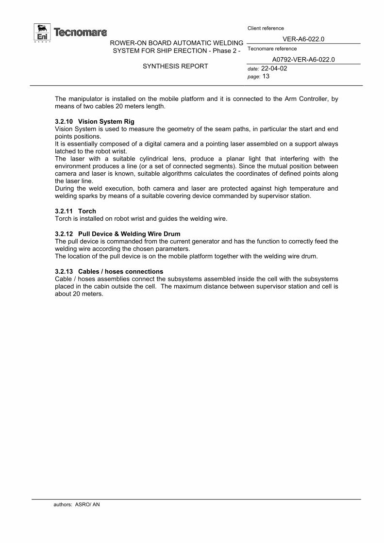
A0792-VER-A6-022.0 date: 22-04-02 page: 13
The manipulator is installed on the mobile platform and it is connected to the Arm Controller, by means of two cables 20 meters length.
3.2.10 Vision System Rig Vision System is used to measure the geometry of the seam paths, in particular the start and end points positions. It is essentially composed of a digital camera and a pointing laser assembled on a support always latched to the robot wrist. The laser with a suitable cylindrical lens, produce a planar light that interfering with the environment produces a line (or a set of connected segments). Since the mutual position between camera and laser is known, suitable algorithms calculates the coordinates of defined points along the laser line. During the weld execution, both camera and laser are protected against high temperature and welding sparks by means of a suitable covering device commanded by supervisor station.
3.2.11 Torch Torch is installed on robot wrist and guides the welding wire.
3.2.12 Pull Device & Welding Wire Drum The pull device is commanded from the current generator and has the function to correctly feed the welding wire according the chosen parameters. The location of the pull device is on the mobile platform together with the welding wire drum.
3.2.13 Cables / hoses connections Cable / hoses assemblies connect the subsystems assembled inside the cell with the subsystems placed in the cabin outside the cell. The maximum distance between supervisor station and cell is about 20 meters.
authors: ASRO/ AN

ROWER-ON BOARD AUTOMATIC WELDING SYSTEM FOR SHIP ERECTION - Phase 2 -
SYNTHESIS REPORT
Client reference
VER-A6-022.0 Tecnomare reference
A0792-VER-A6-022.0 date: 22-04-02 page: 14
INS
IDE
CE
LL
Mobile Platform
Pull Device
UnitCleaningTorch
- wel
ding
cur
r ent
CA
BLE
S /
HO
SE
S A
SS
EM
BLI
ES
- sh e
eldi
ng g
as- w
eld i
ng w
ire- c
oolin
g w
ater
- com
pres
s ai
r- a
rm s
uppl
y an
d si
gnal
s- p
ull d
e vic
e &
torc
h cl
eani
ng u
nits
- vis
ion
syst
em p
ower
sup
ply
& si
gna l
s
Res
e rvo
irG
as
Gen
e rat
ion
Coo
ling
Cur
rent
Wat
er
Air
Com
man
dIn
terp
rete
r
Sen s
orC
urre
nt CO
NTR
OLL
ERAR
M
Gen
era t
ion
Traj
ecto
ry
Softw
are
Wel
din g
Ma n
ager
UN
ITM
AIN
CO
NT R
OL
Dat
a Ba
se
Off
Line
Arm
Tas
kG
ener
ator
Plat
form
Mo b
ile
Gen
erat
orTa
sk
Mo d
ules
Syst
em
Man
ager
Visi
on S
yste
m
Keyb
oard
&M
onito
r
Mou
se
TVMon
itor
CA
BIN
Gas e.v.
CO
NTR
OLL
ERPL
ATFO
RM
Pend
ant
Arm
Teac
h
Teac
hPe
ndan
t
Plat
form
Wire
Wel
d ing
Dru
m
Man
ager
Ma n
ager
On
Line
Dat
a Ba
se
Syst
em
fig. 1.2 - System architecture
authors: ASRO/ AN

ROWER-ON BOARD AUTOMATIC WELDING SYSTEM FOR SHIP ERECTION - Phase 2 -
SYNTHESIS REPORT
Client reference
VER-A6-022.0 Tecnomare reference
A0792-VER-A6-022.0 date: 22-04-02 page: 15
3.3 Operative Sequence The sequence of operations required to weld inside the cell is below described: Off-Line Phase 1. Definition Of The Cell Geometry By Means Of The Database Manager
The operator has to provide the following information: cell geometrical parameters technological welding parameters robotic arm kinematics platform kinematics
On the base of these information an automatic procedure calculates the platform positions required to execute all the welds. For each position of the platform a set of feasible welds is associated. All data are then recorded on some “hidden” files. The estimated required time is 30 minutes for a trained operator
2. Assembling of the System Inside The Cell The part of the automatic welding system to be assembled inside the cell is composed by
the following groups (previously assembled): Vertical guide Mobile platform - torch cleaning device - push device Manipulator - Vision system rig - welding torch Welding wire drum
Each subsystem is then connected to the Main Control station by means of the relevant cables and hoses and the platform position with respect to the cell reference frame is measured and introduced in the database.
On-Line Phase 3. Move the Platform to the Computed Position
From the initial position, the operator command the platform to move to the location associated with the first group of welds.
4. Measurement of the weld position The position of the seam paths with respect to the current arm reference frame is not known
with the enough accuracy due to the following reasons (the expected total error is of the order of 10 mm):
difference between nominal and actual position of the structural members accuracy of the platform positioning error in the calibration of the platform initial position
The Vision System is used to measure the actual geometry of the seam paths (position of the initial and end points, actual amount of gap). The operation is performed in two steps: first the system manager commands the arm to place the vision system rig in correspondence of the nominal starting point of the weld, subsequently the operator (by means of the TV camera) guides the laser line just in correspondence of the actual initial point and the Vision System calculates the actual coordinates. The operation is performed also for the end point and repeated for all the welds feasible from the current platform position.
5. Weld Execution The operator pressing a suitable button on the graphical interface (or teach pendant) commands the execution of the welds previously measured.
authors: ASRO/ AN

ROWER-ON BOARD AUTOMATIC WELDING SYSTEM FOR SHIP ERECTION - Phase 2 -
SYNTHESIS REPORT
Client reference
VER-A6-022.0 Tecnomare reference
A0792-VER-A6-022.0 date: 22-04-02 page: 16
After the execution of each weld the a wire cutting and torch cleaning operations should be automatically performed. The estimated time for a group of three welds is 5 minutes (assuming one pass).
6. Move The Platform To The Next Location And Repeat Operations 4 And 5
After to have stowed the arm in a proper safe position, the platform is displaced to the next calculated location. Then the operations described at the points 4 and 5 are repeated up to the completion of the welds inside the cell.
authors: ASRO/ AN

ROWER-ON BOARD AUTOMATIC WELDING SYSTEM FOR SHIP ERECTION - Phase 2 -
SYNTHESIS REPORT
Client reference
VER-A6-022.0 Tecnomare reference
A0792-VER-A6-022.0 date: 22-04-02 page: 17
Fig. 3.2-2 - Robotic arm
authors: ASRO/ AN

ROWER-ON BOARD AUTOMATIC WELDING SYSTEM FOR SHIP ERECTION - Phase 2 -
SYNTHESIS REPORT
Client reference
VER-A6-022.0 Tecnomare reference
A0792-VER-A6-022.0 date: 22-04-02 page: 18
Fig. 3.2-3 - Arm Controller And Relevant Tech Pendant
authors: ASRO/ AN

ROWER-ON BOARD AUTOMATIC WELDING SYSTEM FOR SHIP ERECTION - Phase 2 -
SYNTHESIS REPORT
Client reference
VER-A6-022.0 Tecnomare reference
A0792-VER-A6-022.0 date: 22-04-02 page: 19
Figure 3.2-4 .- Mobile platform installed on the mock-up
Fig. 3.2-5 - Mobile platform power supply and control unit
authors: ASRO/ AN

ROWER-ON BOARD AUTOMATIC WELDING SYSTEM FOR SHIP ERECTION - Phase 2 -
SYNTHESIS REPORT
Client reference
VER-A6-022.0 Tecnomare reference
A0792-VER-A6-022.0 date: 22-04-02 page: 20
Fig. 3.2-6 - Current Generator
Fig. 3.2-7 - Current sensor
authors: ASRO/ AN

ROWER-ON BOARD AUTOMATIC WELDING SYSTEM FOR SHIP ERECTION - Phase 2 -
SYNTHESIS REPORT
Client reference
VER-A6-022.0 Tecnomare reference
A0792-VER-A6-022.0 date: 22-04-02 page: 21
Fig. 3.2-8 - Supervisor Computer
Fig. 3.2-9 - Vision System Rig
authors: ASRO/ AN

ROWER-ON BOARD AUTOMATIC WELDING SYSTEM FOR SHIP ERECTION - Phase 2 -
SYNTHESIS REPORT
Client reference
VER-A6-022.0 Tecnomare reference
A0792-VER-A6-022.0 date: 22-04-02 page: 22
3.4 Site trials The system has been integrated at Tecnomare laboratory to carry out the preliminary trials using a cell mock-up built in real scale. The mock-up representing the vertical wall of the cell is shown in figure 3.4.1 while in figure 3.4-2a-b is reported the welding system assembled on the mock-up.
figure 3.4.1 Mock-up representing the vertical wall of the cell
authors: ASRO/ AN

ROWER-ON BOARD AUTOMATIC WELDING SYSTEM FOR SHIP ERECTION - Phase 2 -
SYNTHESIS REPORT
Client reference
VER-A6-022.0 Tecnomare reference
A0792-VER-A6-022.0 date: 22-04-02 page: 23
Fig. 3.4-2a Welding system assembled on the mock-up during the site trials
Fig. 3.4-2b Welding system assembled on the mock-up during the site trial
authors: ASRO/ AN

ROWER-ON BOARD AUTOMATIC WELDING SYSTEM FOR SHIP ERECTION - Phase 2 -
SYNTHESIS REPORT
Client reference
VER-A6-022.0 Tecnomare reference
A0792-VER-A6-022.0 date: 22-04-02 page: 24
4 EXPLOITATION PLAN AND FOLLOW-UP ACTIONS It is envisaged to follow this project in a second step: a BRITE EURAM project, named ROWER-2, which includes the same basic components (mobile platform, manipulator, welding equipment, vision system and control console), but aims at expanding the objectives of this project, referred ROWER-1 as . After a successful completion of this ROWER-2, in the following first two years, the project will concentrate on final and completed system development and internal exploitation of the results. The prototype needs to be extensively tested in field and adjusted to achieve the necessary confidence on its operating performances and its reliability, in variable conditions. The two big shipyards users, FINCANTIERI and IZAR are planning to use the mobile robot welding system inside their companies, which relates to eleven shipyards. They also have the intention of collaborating with other partners, after completion, in the development of the marketable final product.
5 REFERENCES
1. European Commission DG III "The Maritime Industries' R&D Masterplan". Workshop on 13 March 1997
2. Documentation from Rower -1 project :
project 7229, contract BRE2-CT 94 - 0925
3. Henrik Rucher, Peer Toftner & Paal Vaagenes "Computer Integration of CAD Modeling And Robotized Shopfloor Production Systems in Shipyards". ICCAS. Bremen. 1994
4. Miyazaki, K. Hebaru, Y. Noborikawa, F. Katayama & H. Yamada "Operation Linkage Technology between CAD, CAM and Robot Systems Applicable to 3 D Curved Blacks in Shipbuilding". ICCAS. Bremen. 1994
5. Stephane Neuveglise"Use of Welding Robots in Shipbuilding Industry: The Need for a Link
with a CAD System". ICCAS. Bremen. 1994. 6. Frank Hollenberg "Off-line Programming of ARC Welding Robots in Shipbuilding" ICCAS.
Bremen. 1994. 7. Svein 1. Sagatun "CIM Solutions for the Shipbuilding Industry". KCS-UM-1995.
8. Gilliland Company "Development of an All Position Automatic Welding Machine". UMTRI.
1976 9. Todd Pacific Shipyard Corporation "Unimation "Apprentice" Welding Robot for Shipyard
Application".UMTRI. 1983. 10. Todd Pacific Shipyard Corporation "Cincinnati Milacron T,, Robot f or Shipbuilding
Welding". UMTRI. 1984 11. 10. Todd Pacific Shipyard Corporation "Robotics in Shipbuilding Workshop Proceedings
with Executive Sunmmary". UMTRI. 1981
authors: ASRO/ AN

ROWER-ON BOARD AUTOMATIC WELDING SYSTEM FOR SHIP ERECTION - Phase 2 -
SYNTHESIS REPORT
Client reference
VER-A6-022.0 Tecnomare reference
A0792-VER-A6-022.0 date: 22-04-02 page: 25
12. Dennis W. Hamify "Robotics in Shipbuilding". ITT Research Institute. 1974
13. Torsten H. Lindbom "Apprentice - A Portable Welding Robot for the Shipbuilding Industry".
Unimation. REAPS 1978 14. John W. Hill "New Applications of Industrial Robots to Shipbuilding" SRI International.
REAPS 1980. 15. Adolfsson, K. Ericson, and A. "Automatic detection of burn-through in GMA welding using
a parametric model", Mechanical Systems and Signal Processing, 10(5):633-651, 1996. 16. Stefan Adolfsson, Ali Bahrami, and Ingvar Claesson "Quality monitoring in robotised
welding using sequential probability ratio test", Proceedings of TENCO '96, Digital Signal Processing Applications, volume 2, pages 635-640, Perth, Western Australia, 27-29 November 1996. IEEE.
6 COLLABORATION SOUGHT Presently we are not seeking any type of collaboration for the exploitation of the results.
authors: ASRO/ AN