Brochure
16
1 DF40 Series 0.4 mm Contact Pitch Board-to-Board /Board-to-FPC Connectors 2012.3e ■Features 1. Higher density of the board-mounted components Extremely small board mounting pattern and low above- the-board profile makes the connectors ideally suited for small device applications. 2. Stacking height variation : 1.5mm to 4.0mm 3. High contact reliability Despite connectors small size and low profile the contacts provide strong contact forces and long contact wipe (0.45 mm), guaranteeing reliable electrical and mechanical performance. 4. Large self-alignment distance The connectors will self-align within 0.33 mm. 5. Confirmation of the fully mated condition Positive “click” sensation confirms correct insertion and connection of all contacts. 6. Built-in shock absorbing feature The protrusions and indents in the insulator bodies protect the connectors from failures when exposed to sudden impact. 7. Solder wicking prevention Nickel-plated barriers provide protection against solder wicking into the contact areas. 8. Contact area protection External walls protect the exposed contact areas from intrusion of flux or foreign particles. Other HRS connector DF40 3.38mm 5.0mm Smaller width Decrease in the board-occupied area High contact reliability – Effective connection wipe of 0.45 mm 1.5mm 0.45mm Interlock indentations (for 10 to 50 positions) Shock-absorbing rib Stacking Height variation Stacking Height 1.5mm 2.0mm 2.5mm 3.0mm 3.5mm 4.0mm Pos. 10 K ---- ---- ---- ---- ---- 12 ∆ K ---- ---- ---- ---- 20 K K K ---- ---- ---- 24 K K ---- ---- ---- ---- 30 K K ∆ K K ---- 34 K ---- ---- ---- ---- ---- 40 K K K ---- ---- ∆ 44 ---- ∆ ---- K ---- ---- 50 K K K K K K 60 K K K K K K 70 K K ---- K ---- ---- 80 K K ---- K K K 90 K ---- ---- K ---- K 100 K ---- ---- K ---- ---- ∆: Reserved for product expansion
description
Â
Transcript of Brochure
1
DF40 Series
0.4 mm Contact Pitch Board-to-Board /Board-to-FPC Connectors
2012.3e
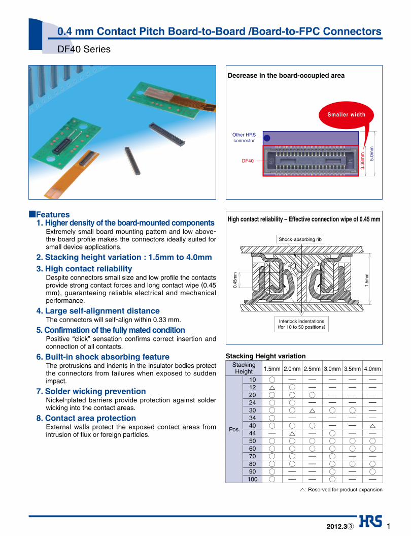
■Features 1. Higher density of the board-mounted components
Extremely small board mounting pattern and low above-the-board profile makes the connectors ideally suited for small device applications.
2. Stacking height variation : 1.5mm to 4.0mm 3. High contact reliability
Despite connectors small size and low profile the contacts provide strong contact forces and long contact wipe (0.45 mm), guaranteeing reliable electrical and mechanical performance.
4. Large self-alignment distanceThe connectors will self-align within 0.33 mm.
5. Confirmation of the fully mated condition Positive “click” sensation confirms correct insertion and connection of all contacts.
6. Built-in shock absorbing feature The protrusions and indents in the insulator bodies protect the connectors from failures when exposed to sudden impact.
7. Solder wicking preventionNickel-plated barriers provide protection against solder wicking into the contact areas.
8. Contact area protectionExternal walls protect the exposed contact areas from intrusion of flux or foreign particles.
Other HRSconnector
DF40
3.38
mm
5.0m
m
Smaller width
Decrease in the board-occupied area
High contact reliability – Effective connection wipe of 0.45 mm
1.5m
m
0.45
mm
Interlock indentations (for 10 to 50 positions)
Shock-absorbing rib
Stacking Height variationStackingHeight 1.5mm 2.0mm 2.5mm 3.0mm 3.5mm 4.0mm
Pos.
10 K ---- ---- ---- ---- ----12 ∆ K ---- ---- ---- ----20 K K K ---- ---- ----24 K K ---- ---- ---- ----30 K K ∆ K K ----34 K ---- ---- ---- ---- ----40 K K K ---- ---- ∆44 ---- ∆ ---- K ---- ----50 K K K K K K
60 K K K K K K
70 K K ---- K ---- ----80 K K ---- K K K
90 K ---- ---- K ---- K
100 K ---- ---- K ---- ----
∆: Reserved for product expansion

DF40 Series●0.4 mm Contact Pitch Board-to-Board /Board-to-FPC Connectors
2
■Materials
■Product Specifications
■Ordering information
DF40 # - * DP - 0.4 V (**) ●Headerq w e y ur t
DF40 # (**) - * DS - 0.4 V (**)q ew r u it y
●Receptacle
RatingsCurrent rating 0.3A
Voltage rating 30V AC, DC
Operation temperature range -35ç to +85ç (Note 1)
Operation humidity range RH 20% to 80%
Storage temperature range -10ç to +60ç (Note 2)
Storage humidity range RH 40% to 70% (Note 2)
Product Part Material Finish Remarks
ReceptaclesHeaders
Insulator LCP Color : Black UL94V-0
Contacts Phosphor bronze Gold plated -------------
Item Specification Conditions
1. Insulation resistance 50 Mø min. 100V DC
2. Withstanding voltage No flashover or insulation breakdown. 100V AC / one minute
3. Contact resistance 90 mø max. 1mA, 20mV AC, 1 kHz
4. Vibration No electrical discontinuity of 1 µs or more. Frequency: 10 to 55 Hz, single amplitude of 0.75mm, 2 hours, 3 axis
5. HumidityContact resistance: 90 mø max.IInsulation resistance: 25 Mø min.
96 hours at +40±2ç and humidity of 90% to 95%.
6. Temperature cycleContact resistance: 90 m ø max.Insulation resistance: 50 Mø min.
Temperature: -55➝+5ç to 35ç➝+85ç➝+5ç to +35çTime: 30➝10➝30➝10 (Minutes)5 cycles
7. Durability (insertion/withdrawal)
Contact resistance: 90 mø max. 30 cycles
8. Resistance to soldering heat
No deformation of components affecting performance.
Reflow: At the recommended temperature profile Manual soldering: 350ç for 3 seconds
Note 1: Includes temperature rise caused by current flow.Note 2: The term “storage” refers to products stored for long period of time prior to mounting and use. Operating temperature range
and humidity range covers non-conducting condition of installed connectors in storage, shipment or during transportation.
q Series Name : DF40
w Configuration
C: Without metal fittings
HC: Without metal fittings
(Stacking height : 2.5mm to 4.0mm)
q Series Name : DF40
w Configuration
C: Without metal fittings
e Stacking Height
r Number of Contacts
e Number of Contacts
r Connector Type
DP : Double-row pin header
t Connector Type DS : Double-row receptacle
y Contact Pitch : 0.4mm
u Terminal Type V: SMT vertical mount
i Packaging
(51) : Embossed tape packaging
t Contact Pitch : 0.4mm
y Terminal Type V: SMT vertical mount
u Packaging
(51) : Embossed tape packaging
Stacking Height
Blank 1.5mm
2.0 2.0mm
2.5 2.5mm
3.0 3.0mm
3.5 3.5mm
4.0 4.0mm
DF40 Series●0.4 mm Contact Pitch Board-to-Board /Board-to-FPC Connectors
3
2.88
±0.
2
3.38
±0.
2
Pick-and-place area : C±0.2
B±0.08
HRS logo
P=0.4±0.05
A±0.2
0.12±0.02
Cavity identification
D±
0.15
Note 2
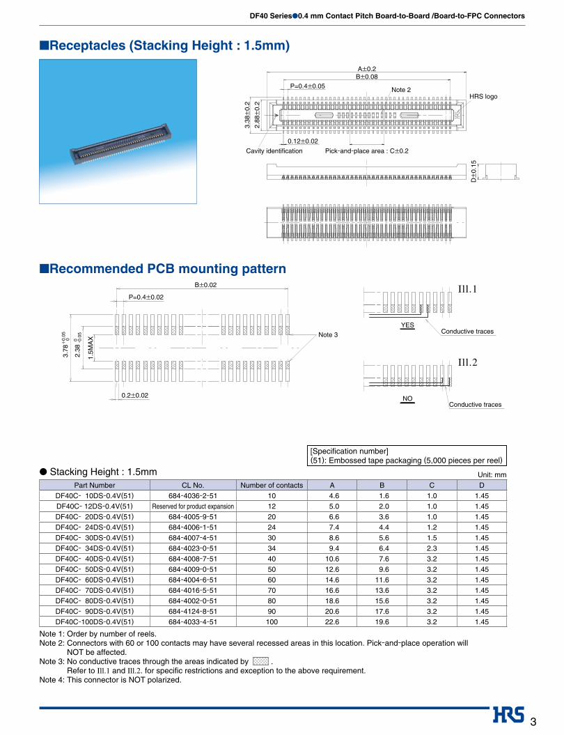
■Receptacles (Stacking Height : 1.5mm)
[Specification number](51): Embossed tape packaging (5,000 pieces per reel)
Ill.1
Ill.2
B±0.02
Note 3
YES
NO
P=0.4±0.02
0.2±0.02
3.78
+0.
05 0
2.38
0 -0.0
5
1.5M
AX
Conductive traces
Conductive traces
■Recommended PCB mounting pattern
Unit: mm● Stacking Height : 1.5mmPart Number CL No. Number of contacts A B C D
DF40C- 10DS-0.4V(51) 684-4036-2-51 10 4.6 1.6 1.0 1.45
DF40C- 12DS-0.4V(51) Reserved for product expansion 12 5.0 2.0 1.0 1.45
DF40C- 20DS-0.4V(51) 684-4005-9-51 20 6.6 3.6 1.0 1.45
DF40C- 24DS-0.4V(51) 684-4006-1-51 24 7.4 4.4 1.2 1.45
DF40C- 30DS-0.4V(51) 684-4007-4-51 30 8.6 5.6 1.5 1.45
DF40C- 34DS-0.4V(51) 684-4023-0-51 34 9.4 6.4 2.3 1.45
DF40C- 40DS-0.4V(51) 684-4008-7-51 40 10.6 7.6 3.2 1.45
DF40C- 50DS-0.4V(51) 684-4009-0-51 50 12.6 9.6 3.2 1.45
DF40C- 60DS-0.4V(51) 684-4004-6-51 60 14.6 11.6 3.2 1.45
DF40C- 70DS-0.4V(51) 684-4016-5-51 70 16.6 13.6 3.2 1.45
DF40C- 80DS-0.4V(51) 684-4002-0-51 80 18.6 15.6 3.2 1.45
DF40C- 90DS-0.4V(51) 684-4124-8-51 90 20.6 17.6 3.2 1.45
DF40C-100DS-0.4V(51) 684-4033-4-51 100 22.6 19.6 3.2 1.45
Note 1: Order by number of reels.Note 2: Connectors with 60 or 100 contacts may have several recessed areas in this location. Pick-and-place operation will
NOT be affected. Note 3: No conductive traces through the areas indicated by .
Refer to Ill.1 and Ill.2. for specific restrictions and exception to the above requirement.Note 4: This connector is NOT polarized.

DF40 Series●0.4 mm Contact Pitch Board-to-Board /Board-to-FPC Connectors
4
[Specification number](51): Embossed tape packaging (4,000 pieces per reel)
Unit: mm● Stacking Height : 2.0mmD
±0.
152.
94±
0.2
3.38
±0.
2
0.12±0.02
P=0.4±0.05
Pick-and-place area : C±0.2
B±0.08A±0.2
■Receptacles (Stacking Height : 2.0mm)
Ill.1
Ill.2
YES
NO0.2±0.02
P=0.4±0.05
3.78
2.38
1.5M
AX
B±0.02
0 -0.0
5
+0.
05
0
Conductive traces
Conductive traces
■Recommended PCB mounting pattern
Part Number CL No. Number of contacts A B C D
DF40C(2.0)- 12DS-0.4V(51) 684-4148-6-51 12 5.0 2.0 1.0 1.95
DF40C(2.0)- 20DS-0.4V(51) 684-4040-0-51 20 6.6 3.6 1.0 1.95
DF40C(2.0)- 24DS-0.4V(51) 684-4021-2-51 24 7.4 4.4 1.2 1.95
DF40C(2.0)- 30DS-0.4V(51) 684-4058-5-51 30 8.6 5.6 1.5 1.95
DF40C(2.0)- 40DS-0.4V(51) 684-4042-5-51 40 10.6 7.6 3.2 1.95
DF40C(2.0)- 44DS-0.4V(51) Reserved for product expansion 44 11.4 8.4 3.2 1.95
DF40C(2.0)- 50DS-0.4V(51) 684-4091-0-51 50 12.6 9.6 3.2 1.95
DF40C(2.0)- 60DS-0.4V(51) 684-4034-7-51 60 14.6 11.6 3.2 1.95
DF40C(2.0)- 70DS-0.4V(51) 684-4147-3-51 70 16.6 13.6 3.2 1.95
DF40C(2.0)- 80DS-0.4V(51) 684-4132-6-51 80 18.6 15.6 3.2 1.95
Note 1: Order by number of reels.Note 2: Connectors with 60 or 100 contacts may have several recessed areas in this location. Pick-and-place operation will
NOT be affected. Note 3: No conductive traces through the areas indicated by .
Refer to Ill.1 and Ill.2. for specific restrictions and exception to the above requirement.Note 4: This connector is NOT polarized.

DF40 Series●0.4 mm Contact Pitch Board-to-Board /Board-to-FPC Connectors
5
A±0.2B±0.08
2.94
±0.
2
3.38
±0.
2
D±
0.15
Pick-and-place area : C±0.2
0.12±0.02
P=0.4±0.05
■Receptacles (Stacking Height : 2.5mm to 4.0mm)
3.78
+0.
05
0
2.38
0 -0.0
5
B±0.02
P=0.4±0.02
0.2±0.02
Ill.1
Ill.2
YES
NO
0.92
MA
X
Conductive traces
Conductive traces
■Recommended PCB mounting pattern
[Specification number](51): Embossed tape packaging (3,000 pieces per reel)
Unit: mm● Stacking Height : 2.5mm
[Specification number](51): Embossed tape packaging (3,000 pieces per reel)
Unit: mm● Stacking Height : 3.0mmPart Number CL No. Number of contacts A B C D
DF40HC(3.0)- 30DS-0.4V(51) 684-4098-0-51 30 8.6 5.6 1.5 2.9
DF40HC(3.0)- 44DS-0.4V(51) 684-4076-7-51 44 11.4 8.4 3.2 2.9
DF40HC(3.0)- 50DS-0.4V(51) 684-4099-2-51 50 12.6 9.6 3.2 2.9
DF40HC(3.0)- 60DS-0.4V(51) 684-4100-0-51 60 14.6 11.6 3.2 2.9
DF40HC(3.0)- 70DS-0.4V(51) 684-4138-2-51 70 16.6 13.6 3.2 2.9
DF40HC(3.0)- 80DS-0.4V(51) 684-4180-9-51 80 18.6 15.6 3.2 2.9
DF40HC(3.0)- 90DS-0.4V(51) 684-4161-4-51 90 20.6 17.6 3.2 2.9
DF40HC(3.0)- 100DS-0.4V(51) 684-4151-0-51 100 22.6 19.6 3.2 2.9
Note 1: Order by number of reels.Note 2: Connectors with 60 or 100 contacts may have several recessed areas in this location. Pick-and-place operation will NOT be affected. Note 3: No conductive traces through the areas indicated by .
Refer to Ill.1 and Ill.2. for specific restrictions and exception to the above requirement.Note 4: This connector is NOT polarized.
Part Number CL No. Number of contacts A B C D
DF40HC(2.5)- 20DS-0.4V(51) 684-4126-3-51 20 6.6 3.6 1.0 2.4
DF40HC(2.5)- 30DS-0.4V(51) Reserved for product expansion 30 8.6 5.6 1.5 2.4
DF40HC(2.5)- 40DS-0.4V(51) 684-4112-9-51 40 10.6 7.6 3.2 2.4
DF40HC(2.5)- 50DS-0.4V(51) 684-4101-2-51 50 12.6 9.6 3.2 2.4
DF40HC(2.5)- 60DS-0.4V(51) 684-4085-8-51 60 14.6 11.6 3.2 2.4

DF40 Series●0.4 mm Contact Pitch Board-to-Board /Board-to-FPC Connectors
6
[Specification number](51): Embossed tape packaging (2,000 pieces per reel)
Unit: mm● Stacking Height : 3.5mm
[Specification number](51): Embossed tape packaging (2,000 pieces per reel)
Unit: mm● Stacking Height : 4.0mmPart Number CL No. Number of contacts A B C D
DF40HC(4.0)- 40DS-0.4V(51) Reserved for product expansion 40 10.6 7.6 3.2 3.9
DF40HC(4.0)- 50DS-0.4V(51) 684-4104-0-51 50 12.6 9.6 3.2 3.9
DF40HC(4.0)- 60DS-0.4V(51) 684-4133-9-51 60 14.6 11.6 3.2 3.9
DF40HC(4.0)- 80DS-0.4V(51) 684-4140-4-51 80 18.6 15.6 3.2 3.9
DF40HC(4.0)- 90DS-0.4V(51) 684-4165-5-51 90 20.6 17.6 3.2 3.9
Note 1: Order by number of reels.Note 2: Connectors with 60 or 100 contacts may have several recessed areas in this location. Pick-and-place operation will NOT be affected. Note 3: No conductive traces through the areas indicated by .
Refer to Ill.1 and Ill.2. for specific restrictions and exception to the above requirement.Note 4: This connector is NOT polarized.
Part Number CL No. Number of contacts A B C D
DF40HC(3.5)- 30DS-0.4V(51) 684-4136-7-51 30 8.6 5.6 1.5 3.4
DF40HC(3.5)- 50DS-0.4V(51) 684-4109-4-51 50 12.6 9.6 3.2 3.4
DF40HC(3.5)- 60DS-0.4V(51) 684-4102-5-51 60 14.6 11.6 3.2 3.4
DF40HC(3.5)- 80DS-0.4V(51) 684-4162-7-51 80 18.6 15.6 3.2 3.4

DF40 Series●0.4 mm Contact Pitch Board-to-Board /Board-to-FPC Connectors
7
B±0.08
Pick-and-place area : C±0.2
1.85
±0.
2
P=0.4±0.05
A±0.2
2.97
±0.
2
0.15±0.02
1.14
±0.
15
■Header
B±0.02
P=0.4±0.02 0.3±0.02
0.65±0.02
3.37
+0.
05 0
2.05
0 -0.0
5
0.23±0.02 0.35±0.02
■Recommended PCB mounting pattern
Unit: mm
[Specification number](51): Embossed tape packaging (5,000 pieces per reel)
Part Number CL No. Number of contacts A B C
DF40C- 10DP-0.4V(51) 684-4035-0-51 10 3.52 1.6 1.0
DF40C- 12DP-0.4V(51) 684-4149-9-51 12 3.92 2.0 1.0
DF40C- 20DP-0.4V(51) 684-4010-9-51 20 5.52 3.6 1.0
DF40C- 24DP-0.4V(51) 684-4011-1-51 24 6.32 4.4 1.2
DF40C- 30DP-0.4V(51) 684-4012-4-51 30 7.52 5.6 1.5
DF40C- 34DP-0.4V(51) 684-4024-3-51 34 8.32 6.4 2.3
DF40C- 40DP-0.4V(51) 684-4013-7-51 40 9.52 7.6 3.2
DF40C- 44DP-0.4V(51) 684-4077-0-51 44 10.32 8.4 3.2
DF40C- 50DP-0.4V(51) 684-4014-0-51 50 11.52 9.6 3.2
DF40C- 60DP-0.4V(51) 684-4003-3-51 60 13.52 11.6 3.2
DF40C- 70DP-0.4V(51) 684-4015-2-51 70 15.52 13.6 3.2
DF40C- 80DP-0.4V(51) 684-4001-8-51 80 17.52 15.6 3.2
DF40C- 90DP-0.4V(51) 684-4125-0-51 90 19.52 17.6 3.2
DF40C-100DP-0.4V(51) 684-4032-1-51 100 21.52 19.6 3.2
Note 1: Order by number of reels.Note 2: 60 or 100 positions connectors will not have small interlock indentations in the contact areas. Note 3: The contacts in each of the 4 corners serve as metal solder brackets only and should NOT be used for current carrying. Note 4: Location of the HRS logo and cavity identification mark may differ from what is shown. Note 5: This connector is not polarized.

DF40 Series●0.4 mm Contact Pitch Board-to-Board /Board-to-FPC Connectors
8
A
A
Unreeling direction
G G
2±0.5
120˚
8±0.1 H
Ø1.5
2±0.14±0.1
F 1.75
±0.
1C
±0.
1B
±0.
1A
±0.
3
F-F
0.3±0.1
1.65
±0.
15
R0.75
R0.75H
0.2±
0.05
Ø21±0.8
Part number label
Ø13±
0.2
Ø380
±2
Ø80±
1
E±0.5D±1
120˚
F
G-G
+0.1 0
+0.1
0
+0.1
0
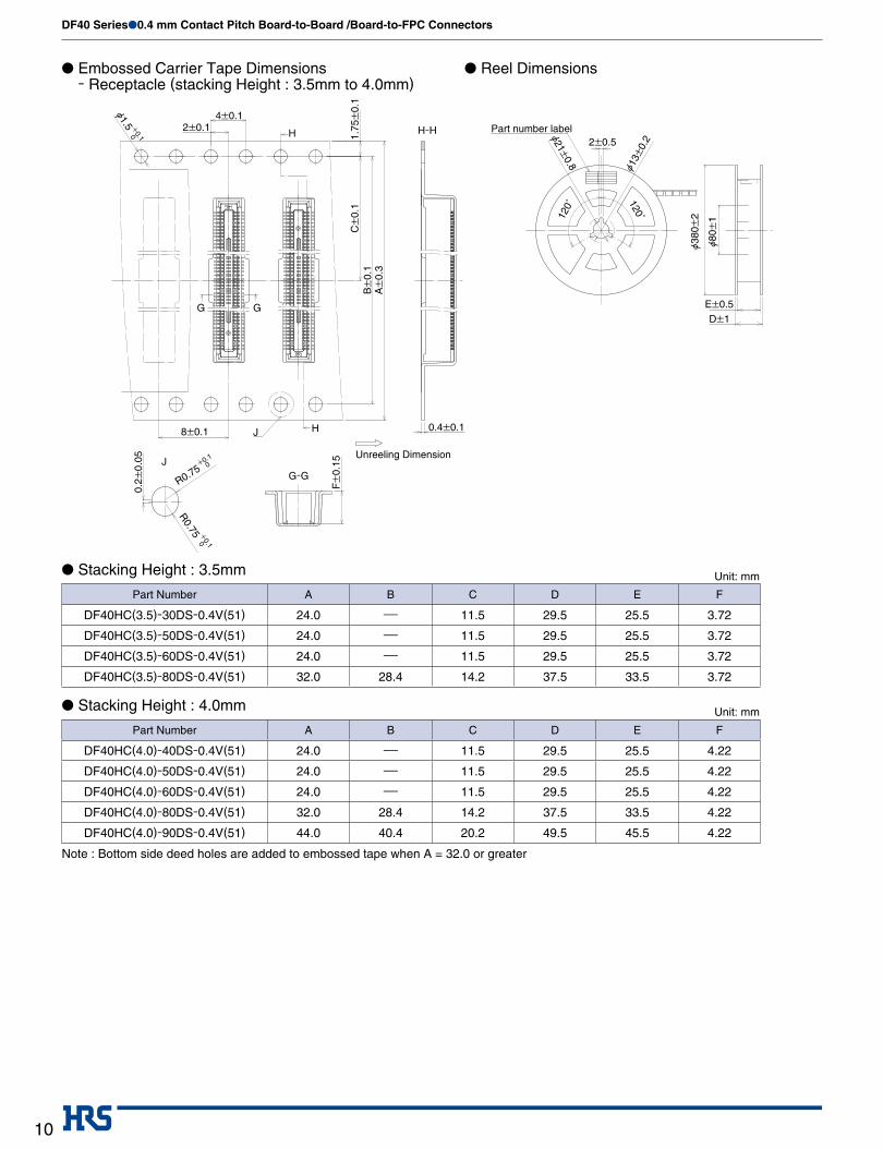
■Packaging Specification ● Embossed Carrier Tape Dimensions
- Receptacle (stacking Height : 1.5mm)
● Stacking Height : 1.5mm Unit: mm
● Reel Dimensions
Part Number A B C D E
DF40C- 10DS-0.4V(51) 16.0 ---- 7.5 21.5 17.5
DF40C- 12DS-0.4V(51) 16.0 ---- 7.5 21.5 17.5
DF40C- 20DS-0.4V(51) 16.0 ---- 7.5 21.5 17.5
DF40C- 24DS-0.4V(51) 16.0 ---- 7.5 21.5 17.5
DF40C- 30DS-0.4V(51) 24.0 ---- 11.5 29.5 25.5
DF40C- 34DS-0.4V(51) 24.0 ---- 11.5 29.5 25.5
DF40C- 40DS-0.4V(51) 24.0 ---- 11.5 29.5 25.5
DF40C- 50DS-0.4V(51) 24.0 ---- 11.5 29.5 25.5
DF40C- 60DS-0.4V(51) 24.0 ---- 11.5 29.5 25.5
DF40C- 70DS-0.4V(51) 32.0 28.4 14.2 37.5 33.5
DF40C- 80DS-0.4V(51) 32.0 28.4 14.2 37.5 33.5
DF40C- 90DS-0.4V(51) 44.0 40.4 20.2 49.5 45.5
DF40C-100DS-0.4V(51) 44.0 40.4 20.2 49.5 45.5
Note : Bottom side deed holes are added to embossed tape when A = 32.0 or greater

DF40 Series●0.4 mm Contact Pitch Board-to-Board /Board-to-FPC Connectors
9
2±0.5
5
J
G G
H
Unreeling direction
Part number label0.
2±0.
05
R0.75
F±
0.15
J8±0.1
Ø1.5 2±0.14±0.1
H 1.75
±0.
1
H-H
Ø13±
0.2Ø21±
0.8
120˚
120˚
Ø380
±2
Ø80±
1
E±0.5D±1
G-G
+0.1
0
R0.75+0.1
0
0.3±0.1
A±
0.3
B±
0.1
C±
0.1
+0.1
0
● Embossed Carrier Tape Dimensions - Receptacle (stacking Height : 2.0mm to 3.0mm)
● Stacking Height : 2.0mm Unit: mm
● Stacking Height : 2.5mm Unit: mm
● Stacking Height : 3.0mm Unit: mm
● Reel Dimensions
Part Number A B C D E F
DF40C(2.0)-12DS-0.4V(51) 16.0 ---- 7.5 21.5 17.5 2.2DF40C(2.0)-20DS-0.4V(51) 16.0 ---- 7.5 21.5 17.5 2.2DF40C(2.0)-24DS-0.4V(51) 16.0 ---- 7.5 21.5 17.5 2.2DF40C(2.0)-30DS-0.4V(51) 24.0 ---- 11.5 29.5 25.5 2.2DF40C(2.0)-40DS-0.4V(51) 24.0 ---- 11.5 29.5 25.5 2.2DF40C(2.0)-44DS-0.4V(51) 24.0 ---- 11.5 29.5 25.5 2.2DF40C(2.0)-50DS-0.4V(51) 24.0 ---- 11.5 29.5 25.5 2.2DF40C(2.0)-60DS-0.4V(51) 24.0 ---- 11.5 29.5 25.5 2.2DF40C(2.0)-70DS-0.4V(51) 32.0 28.4 14.2 37.5 33.5 2.2DF40C(2.0)-80DS-0.4V(51) 32.0 28.4 14.2 37.5 33.5 2.2
Part Number A B C D E F
DF40HC(2.5)-20DS-0.4V(51) 16.0 ---- 7.5 21.5 17.5 2.72DF40HC(2.5)-30DS-0.4V(51) 24.0 ---- 11.5 29.5 25.5 2.72DF40HC(2.5)-40DS-0.4V(51) 24.0 ---- 11.5 29.5 25.5 2.72DF40HC(2.5)-50DS-0.4V(51) 24.0 ---- 11.5 29.5 25.5 2.72DF40HC(2.5)-60DS-0.4V(51) 24.0 ---- 11.5 29.5 25.5 2.72
Part Number A B C D E F
DF40HC(3.0)-30DS-0.4V(51) 24.0 ---- 11.5 29.5 25.5 3.15DF40HC(3.0)-44DS-0.4V(51) 24.0 ---- 11.5 29.5 25.5 3.15DF40HC(3.0)-50DS-0.4V(51) 24.0 ---- 11.5 29.5 25.5 3.15DF40HC(3.0)-60DS-0.4V(51) 24.0 ---- 11.5 29.5 25.5 3.15DF40HC(3.0)-70DS-0.4V(51) 32.0 28.4 14.2 37.5 33.5 3.15DF40HC(3.0)-80DS-0.4V(51) 32.0 28.4 14.2 37.5 33.5 3.15DF40HC(3.0)-90DS-0.4V(51) 44.0 40.4 20.2 49.5 45.5 3.15DF40HC(3.0)-100DS-0.4V(51) 44.0 40.4 20.2 49.5 45.5 3.15
Note : Bottom side deed holes are added to embossed tape when A = 32.0 or greater
DF40 Series●0.4 mm Contact Pitch Board-to-Board /Board-to-FPC Connectors
10
J
G G
Ø1.5 +0.1
0
2±0.1
J H
Unreeling Dimension
G-G
8±0.1 0.4±0.1
4±0.1
1.75
±0.
1 C
±0.
1 B
±0.
1 A
±0.
3
H H-H Part number label2±0.5
Ø380
±2
Ø80±
1
Ø13±
0.2
120˚
120˚
Ø21±0.8
E±0.5D±1
F±
0.15
0.2
±0.
05
R0.75+0.1
0
R0.75 +
0.1
0
● Embossed Carrier Tape Dimensions - Receptacle (stacking Height : 3.5mm to 4.0mm)
● Stacking Height : 3.5mm Unit: mm
● Stacking Height : 4.0mm Unit: mm
● Reel Dimensions
Part Number A B C D E F
DF40HC(3.5)-30DS-0.4V(51) 24.0 ---- 11.5 29.5 25.5 3.72
DF40HC(3.5)-50DS-0.4V(51) 24.0 ---- 11.5 29.5 25.5 3.72
DF40HC(3.5)-60DS-0.4V(51) 24.0 ---- 11.5 29.5 25.5 3.72
DF40HC(3.5)-80DS-0.4V(51) 32.0 28.4 14.2 37.5 33.5 3.72
Part Number A B C D E F
DF40HC(4.0)-40DS-0.4V(51) 24.0 ---- 11.5 29.5 25.5 4.22
DF40HC(4.0)-50DS-0.4V(51) 24.0 ---- 11.5 29.5 25.5 4.22
DF40HC(4.0)-60DS-0.4V(51) 24.0 ---- 11.5 29.5 25.5 4.22
DF40HC(4.0)-80DS-0.4V(51) 32.0 28.4 14.2 37.5 33.5 4.22
DF40HC(4.0)-90DS-0.4V(51) 44.0 40.4 20.2 49.5 45.5 4.22
Note : Bottom side deed holes are added to embossed tape when A = 32.0 or greater

DF40 Series●0.4 mm Contact Pitch Board-to-Board /Board-to-FPC Connectors
11
A
A
Ø1.5
2±0.14±0.1
F F-F
G
H
H
F
Unreeling Dimension
G-G
0.3±0.1
G
1.75
±0.
1C
±0.
1B
±0.
1A
±0.
3
0.2±
0.05
1.34
±0.
15
+0.1
0
Ø0.75 +0.1
0
Ø0.75+0.1
0
Part number label2±0.5
Ø380
±2
Ø80±
1
Ø13±
0.2
120˚ 120˚
Ø21±0.8
E±0.5D±1
● Embossed Carrier Tape Dimensions - Header
Unit: mm
● Reel Dimensions
Part Number A B C D E
DF40C- 10DP-0.4V(51) 12.0 ---- 5.5 17.5 13.5
DF40C- 12DP-0.4V(51) 12.0 ---- 5.5 17.5 13.5
DF40C- 20DP-0.4V(51) 16.0 ---- 7.5 21.5 17.5
DF40C- 24DP-0.4V(51) 16.0 ---- 7.5 21.5 17.5
DF40C- 30DP-0.4V(51) 16.0 ---- 7.5 21.5 17.5
DF40C- 34DP-0.4V(51) 24.0 ---- 11.5 29.5 25.5
DF40C- 40DP-0.4V(51) 24.0 ---- 11.5 29.5 25.5
DF40C- 44DP-0.4V(51) 24.0 ---- 11.5 29.5 25.5
DF40C- 50DP-0.4V(51) 24.0 ---- 11.5 29.5 25.5
DF40C- 60DP-0.4V(51) 24.0 ---- 11.5 29.5 25.5
DF40C- 70DP-0.4V(51) 32.0 28.4 14.2 37.5 33.5
DF40C- 80DP-0.4V(51) 32.0 28.4 14.2 37.5 33.5
DF40C- 90DP-0.4V(51) 44.0 40.4 20.2 49.5 45.5
DF40C-100DP-0.4V(51) 44.0 40.4 20.2 49.5 45.5
Note : Bottom side deed holes are added to embossed tape when A = 32.0 or greater
DF40 Series●0.4 mm Contact Pitch Board-to-Board /Board-to-FPC Connectors
12
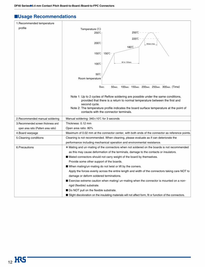
■Usage Recommendations1. Recommended temperature
profile
2.Recommended manual soldering
3. Recommended screen thickness and
open area ratio (Pattern area ratio)
4.Board warpage
5.Cleaning conditions
6.Precautions
* Mating and un-mating of the connectors when not soldered on the boards is not recommended
as this may cause deformation of the terminals, damage to the contacts or insulators.
■ Mated connectors should not carry weight of the board by themselves.
Provide some other support of the boards.
■ When mating/un-mating do not twist or lift by the corners.
Apply the forces evenly across the entire length and width of the connectors taking care NOT to
damage or deform soldered terminations.
■ Exercise extreme caution when mating/ un-mating when the connector is mounted on a non-
rigid (flexible) substrate.
■ Do NOT pull on the flexible substrate.
■ Slight discoloration on the insulating materials will not affect form, fit or function of the connectors.
Cleaning is not recommended. When cleaning, please evaluate as if can deteriorate the
performance including mechanical operation and environmental resistance.
Maximum of 0.02 mm at the connector center, with both ends of the connector as reference points.
Manual soldering: 340±10ç for 3 seconds
Note 1: Up to 2 cycles of Reflow soldering are possible under the same conditions, provided that there is a return to normal temperature between the first and second cycle.
Note 2: The temperature profile indicates the board surface temperature at the point of contacts with the connector terminals.
Thickness: 0.12 mm
Open area ratio: 80%
50ç
60sec.max.
100ç
150ç 150ç
200ç
250çTemperature (ç)
Room temperature
100sec. 150sec. 200sec. 250sec.50sec.0sec. 300sec.
90 to 120sec.
180ç
250ç
220ç
(Time)

DF40 Series●0.4 mm Contact Pitch Board-to-Board /Board-to-FPC Connectors
13
■Handling Precautions when mating the connectors
DF40*-*DP-0.4V
Header
DF40*-*DS-0.4V
Receptacle
Keep the connectors parallel to each other when positioning
Do not attempt to mate the connectors staring at one end or side.
Press-down evenly until slight resistance is felt.Overcoming this slight resistance will complete the mating receptacle with the header. A definite “click” sensation will confirm the fully mated condition.

DF40 Series●0.4 mm Contact Pitch Board-to-Board /Board-to-FPC Connectors
14
■Handling Precautions when un-mating the connectors
DF40*-*DS-0.4V
DF40*-*DP-0.4V
Lift even one side, keeping both boards parallel to each other.
Fully mated
When handling, circumstances prevent the connector from
being kept level during the un-mating. One end may be lifted
separate as shown.
However, to utilize this procedure the connector must be
mounted on a sufficiently rigid circuit board.
Any deflection of the board during this operation may result in
damage to the connectors or solder joints.
Do not attempt the start of the un-mating of the connectors
from one side or corner.
When un-mating is from the width orientation, as illustrated in
the diagram to the left, connector could be damaged. Do not
remove from the width orientation.
Pitch Orientation
Width Orientation
Corner Orientation

DF40 Series●0.4 mm Contact Pitch Board-to-Board /Board-to-FPC Connectors
15
■Handling Precautions when un-mating the connectors
FPC
Receptacle
Header
Receptacle
Header
Low rigidity FPC should not be used for mounting of the
receptacle.
Un-mating of the connectors when the receptacle is mounted
on the extremely flexible FPC can result in solder joint failure
or damage to the connector itself.
It is highly recommended that the receptacle be mounted on
the rigid PCB and the header on the FPC.
Contact HRS when specific application requires mounting of
the receptacle on the FPC.
All published performance data is based on connectors
mounted on rigid FPC and PCB.
Failure to exercise caution when un-mating connectors
mounted on the non-rigid FPC may also result in connector
breakage.

DF40 Series●0.4 mm Contact Pitch Board-to-Board /Board-to-FPC Connectors
16The contents of this catalog are current as of date of 03/2012. Contents are subject to change without notice for the purpose of improvements.
USA:HIROSE ELECTRIC (U.S.A.), INC. San Jose Office20400 Stevens Creek Blvd., Ste 250, Cupertino, CA 95014Phone : +1-408-253-9640Fax : +1-408-253-9641http://www.hiroseusa.com
USA:HIROSE ELECTRIC (U.S.A.), INC. Headquarters2688 Westhills Court, Simi Valley, CA 93065-6235Phone : +1-805-522-7958Fax : +1-805-522-3217http://www.hiroseusa.com
HONG KONG:HIROSE ELECTRIC HONGKONG TRADING CO., LTD.Room 1001, West Wing, Tsim Sha Tsui Centre, 66 Mody Road, Tsim Sha Tsui East, Kowloon, Hong KongPhone : +852-2803-5338 Fax : +852-2591-6560http://www.hirose-hongkong.com.hk
CHINA:HIROSE ELECTRIC (SHANGHAI) CO., LTD. BEIJING BRANCHA1001, Ocean International Center, Building 56# East 4th Ring Middle Road, Chao Yang District, Beijing, 100025Phone : +86-10-5165-9332Fax : +86-10-5908-1381http://www.hirose-china.com.cn
TAIWAN:
HIROSE ELECTRIC TAIWAN CO., LTD.103 8F, No.87, Zhengzhou Rd., TaipeiPhone : +886-2-2555-7377Fax : +886-2-2555-7350 http://www.hirose-taiwan.com.tw
GERMANY:HIROSE ELECTRIC EUROPE B.V. GERMAN BRANCHHerzog-Carl-Strasse 4 D-73760 Ostfildern(Scharnhauser Park)Phone : +49-711-4560-02-1Fax : +49-711-4560-02-299http://www.hirose.de
INDIA:HIROSE ELECTRIC SINGAPORE PTE. LTD. BANGALORE LIAISON OFFICEUnit No.03, Ground Floor, Explorer Building International Tech Park Whitefield Road, Bangalore 560066 Karnataka, IndiaPhone : +65-6324-6113Fax : +65-6324-6123http://www.hirose-singapore.com.sg
SINGAPORE:HIROSE ELECTRIC SINGAPORE PTE. LTD.10 Anson Road #26-16 International Plaza 079903Phone : +65-6324-6113 Fax : +65-6324-6123http://www.hirose-singapore.com.sg
THE NETHERLANDS:HIROSE ELECTRIC EUROPE B.V.Hogehillweg #8 1101 CC Amsterdam Z-OPhone : +31-20-6557460 Fax : +31-20-6557469http://www.hiroseeurope.com
UNITED KINGDOM:HIROSE ELECTRIC EUROPE B.V. UK BRANCHFirst Floor, St Andrews House, Caldecotte Lake Business Park, Milton Keynes MK7 8LEPhone : +44-1908-369060Fax : +44-1908-369078http://www.hirose.co.uk
USA:HIROSE ELECTRIC (U.S.A.), INC. Detroit Office (Automotive)37677 Professional Center Drive, Suite #100C Livonia, MI 48154Phone : +1-734-542-9963Fax : +1-734-542-9964 http://www.hiroseusa.com
CHINA:HIROSE ELECTRIC (SHANGHAI) CO., LTD.1601,Henderson Metropolitan,NO.300 ,East Nanjing Road,Huangpu District, Shanghai,China 200001Phone : +86-21-6391-3355Fax : +86-21-6391-3335 http://www.hirose-china.com.cn
CHINA:HIROSE ELECTRIC TECHNOLOGIES (SHENZHEN) CO., LTD.Room 09-13, 19/F, Office Tower Shun Hing Square, Di Wang Commercial Centre 5002, ShenNanDong Road, ShenZhen City, Guangdong Province, 518008Phone : +86-755-8207-0851Fax : +86-755-8207-0873http://www.hirose-china.com.cn
KOREA:HIROSE KOREA CO., LTD.1261-10, Jeoungwhang-Dong, Shihung-City, Kyunggi-Do 429-450Phone : +82-31-496-7000,7124Fax : +82-31-496-7100http://www.hirose.co.kr
6-3,Nakagawa Chuoh-2-Chome,Tsuzuki-Ku,Yokohama-Shi 224-8540,JAPANTEL: +81-45-620-3526 Fax: +81-45-591-3726http://www.hirose.comhttp://www.hirose-connectors.com
®


![Brochure IFS Applications Brochure 2010[1]](https://static.fdocuments.in/doc/165x107/54f6c2954a7959430c8b48f5/brochure-ifs-applications-brochure-20101.jpg)