Broadcom-supported BES-53248 Cluster Switch Installation Guide
38
Broadcom-supported BES-53248 Cluster Switch Installation Guide 215-14867-B0
Transcript of Broadcom-supported BES-53248 Cluster Switch Installation Guide

Broadcom-supported BES-53248 Cluster Switch
Installation Guide
215-14867-B0


SAFETY & REGULATORY INFORMATION
About the Manual This installation guide is meant for network administrators with in-depth knowledge in network management. To avoid personal injury or property damage, before you begin installing the product, read, observe, and adhere to all the following safety instructions and information. The following symbols are used throughout the guide to highlight important information and may be marked on the product and / or the product packaging.
NOTE
WARNING
CAUTION
Indicates useful information. Indicates safety information that if ignored may cause the system to malfunction or damage other equipment. Indicates safety information that if ignored may cause personal injury or death.
Intended Application Uses This product was evaluated as Information Technology Equipment (ITE). which may be installed in offices, schools, computer rooms, and similar commercial type locations. The suitability of this product for other product categories and environments (such as medical, industrial, residential, alarm systems, and test equipment), other than an ITE application, may require further evaluation.
Safety Information
Switch Safety Information To reduce the risk of body injury, electrical shock, fire, and equipment damage, read this document and observe all warnings and precautions before installing or maintaining your switch. In the event of a conflict between the information in this document and the information provided with the product or on the website of a particular product, the product documentation takes precedence. The switch should be integrated and serviced only by technically qualified persons. You must adhere to the guidelines in this guide and the assembly instructions in the switch manuals to ensure and maintain compliance with existing product certifications and approvals. Use only the described, regulated components specified in this guide. Use of other products / components will void the UL Listing and other regulatory approvals of the product and may result in noncompliance with product regulations in the region(s) in which the product is sold. Follow the safety guidelines below to ensure personal safety and protect the system and the working environment from potential damage.
1 Network Switch Installation Guide

CAUTION • The power supplies in the system may produce high voltages and energy
hazards which can cause bodily harm. Do not remove the covers and access any of the components inside the system.
• To reduce the risk of electrical shock, disconnect all power supply cables before servicing the system.
• Do not use the mounted equipment as a shelf or a workspace. • Restricted Access Location: The switch is intended for installation only in
a Server Room or Computer Room where both these conditions apply: √ access can only be gained by SERVICE PERSONS or by USERS who have
been instructed about the reasons for the restrictions applied to the location and about any precautions that shall be taken; and
√ access is by a TOOL or lock and key, or other means of security, and is controlled by the authority responsible for the location.
WARNING When a power supply needs replacement, replace the power supply only with the same or equivalent type recommended by the manufacturer. Replacing with an incorrect power supply may cause explosion.
• Observe and follow service markings. Do not service the product yourself. Components inside the system should only be serviced by trained service technician.
• If any of the following conditions occur, unplug the equipment from the electrical outlet and replace the part or contact a trained service technician: √ The power cable, extension cable, or plug is damaged √ The equipment has been exposed to water √ The equipment has been dropped or damaged √ The equipment does not operate correctly when you follow the
operating instructions • Do not spill food or liquid on the equipment. • Never operate the equipment in a wet environment. • Do not push any objects into the opening of the equipment. Doing so may short
internal components and cause fire or electric shock. • Use the system only with approved equipment. • Allow the product to cool before removing any peripherals. • Operate the equipment only from the type of external power source indicated on the
electrical ratings label. If you are unsure of the type of power source required, consult your local power company.
• Use only approved power cable(s). • To help prevent electric shock, plug the system and peripheral power cables into
properly grounded electrical outlets. Do not use adapter plugs or remove the grounding prong from a cable. If you must use an extension cable, use an extension cable with properly grounded plugs.
• Observe and follow service markings. Do not service the product yourself. Components inside the system should only be serviced by trained service technician.
• If any of the following conditions occur, unplug the equipment from the electrical outlet and replace the part or contact a trained service technician: √ The power cable, extension cable, or plug is damaged √ The equipment has been exposed to water
Network Switch Installation Guide 2

√ The equipment has been dropped or damaged √ The equipment does not operate correctly when you follow the
operating instructions • Do not spill food or liquid on the equipment. • Never operate the equipment in a wet environment. • Do not push any objects into the opening of the equipment. Doing so may short
internal components and cause fire or electric shock. • Use the system only with approved equipment. • Allow the product to cool before removing any peripherals. • Operate the equipment only from the type of external power source indicated on the
electrical ratings label. If you are unsure of the type of power source required, consult your local power company.
• Use only approved power cable(s). • To help prevent electric shock, plug the system and peripheral power cables into
properly grounded electrical outlets. Do not use adapter plugs or remove the grounding prong from a cable. If you must use an extension cable, use an extension cable with properly grounded plugs.
• Observe extension cable and power strip ratings. Ensure that the total ampere rating of all products plugged into the extension cable or power strip does not exceed 80% of the ampere ratings limit for the extension cable or power strip.
• To protect the equipment from sudden, transient increase or decrease in electrical power, use a surge suppressor, line conditioner, or uninterruptible power supply (UPS).
• Do not modify power cables or plugs. Consult a licensed electrician or your power company for site modifications. Always follow your local/national wiring rules.
• To avoid possible damage to the system board, wait 5 seconds after turning off the system before removing a component from the system board or disconnecting a peripheral device.
• When connecting or disconnecting power to the hot-pluggable power supply units, observe the following guidelines: √ Unplug the power cable before removing the power supply. √ Install the power supply to the system before connecting the power cable to
the power supply. √ If the system has multiple sources of power, disconnect power from the system
by unplugging all power cables from the power supplies. • When disconnecting a cable, pull on its connector or on its strain-relief loop, and
not on the cable itself. 3 Network Switch Installation Guide

Installation Assembly Safety Instructions • The power supply in this product contains no user-serviceable parts. Refer servicing
only to qualified personnel. • Do not attempt to modify or use the supplied AC power cord if it is not the exact type
required. A product with more than one power supply will have a separate AC power cord for each supply.
• To remove the AC power from the system, you must unplug each AC power cord from the wall outlet or power supply. The power cord(s) is considered the disconnect device to the main (AC) power. The socket outlet that the system plugs into shall be installed near the equipment and shall be easily accessible.
• A microprocessor and heat sink may be hot if the system has been running. Also, there may be sharp pins and edges on some board and chassis parts. Contact should be made with care. Consider wearing protective gloves.
• Danger of explosion if the battery is incorrectly replaced. Replace only with the same or equivalent type recommended by the equipment manufacturer. Dispose of used batteries according to manufacturer’s instructions.
• The system is safety certified as rack-mounted equipment for use in a server room or computer room, using the customer rack kit. The rail racks are designed to carry only the weight of the system. Do not place additional load onto any rail-mounted equipment. System rack kits are intended to be installed in a rack by trained service technicians.
Site Selection The system is designed to operate in a typical office environment. Choose a site that is: • Clean and free of airborne particles (other than normal room dust). • Well ventilated and away from sources of heat including direct sunlight and radiators. • Away from sources of vibration or physical shock. • Isolated from strong electromagnetic fields produced by electrical devices. • In regions that are susceptible to electrical storms, we recommend you plug your
system into a surge suppressor and disconnect telecommunication lines to your modem during an electrical storm.
• Provided with a properly grounded wall outlet. • Provided with enough space to access the power supply cord(s), because they serve
as the product’s main power disconnect. • Provided with either two independent AC power sources or two independent
phases from a single source.
Equipment Handling Practices Reduce the risk of personal injury or equipment damage: • Conform to local occupational health and safety requirements when moving and
lifting equipment. • Use mechanical assistance or other suitable assistance when moving and lifting the
equipment. • To reduce the weight for easier handling, remove any easily detachable components.
Power and Electrical Warnings
CAUTION
Network Switch Installation Guide 4
• The power is active whenever the system is plugged in. To remove power from the system, you must unplug the AC power cord from the wall outlet. Your system may use more than one AC power cord. Make sure all AC power cords are unplugged. Make sure the AC power cord(s) is/are unplugged before you open the chassis or add or remove any non hot-plug components.
• Do not attempt to modify or use an AC power cord if it is not the exact type required. A separate AC cord is required for each system power supply.
• The power supply in this product contains no user-serviceable parts. Do not open the power supply. Hazardous voltage, current and energy levels are present inside the power supply. Return to manufacturer for servicing.
• When replacing a hot-plug power supply, unplug the power cord to the power supply being replaced before removing it from the switch.
Power Cord Warnings If an AC power cord was not provided with your product, purchase one that is approved for use in your country.
CAUTION
• To avoid electrical shock or fire, check the power cord(s) that will be used with the product as follows: √ access can only be gained by SERVICE PERSONS or by USERS who
have been instructed about the reasons for the restrictions applied to the location and about any precautions that shall be taken; and
√ access is by a TOOL or lock and key, or other means of security, and is controlled by the authority responsible for the location.
• The power cord must have safety ground pin or contact that is suitable for the electrical outlet.
• The power supply cord(s) is/are the main disconnect device to AC power. The socket outlet(s) must be near the equipment and readily accessible for disconnection.
• The power supply cord(s) must be plugged into socket outlet(s) that is/are provided with a suitable earth ground.
5 Network Switch Installation Guide

System Access Warnings
CAUTION • To avoid personal injury or property damage, the following safety instructions
apply whenever accessing the inside of the product: √ Turn off all peripheral devices connected to this product. √ Disconnect the AC power by unplugging all AC power cords from the
system or wall outlet. √ Disconnect all cables and telecommunication lines that are connected
to the system. √ Retain all screws or other fasteners when removing access cover(s).
Upon completion of accessing inside the product, refasten access cover with original screws or fasteners.
√ Do not access the inside of the power supply. There are no serviceable parts in the power supply. Return to the manufacturer for servicing.
√ Power down the switch and disconnect all power cords before adding or replacing any non hot-plug component.
√ When replacing a hot-plug power supply, unplug the power cord to the power supply being replaced before removing the power supply from the switch.
• Unless you are adding or removing a hot-plug component, allow the system to cool before opening the covers. To avoid the possibility of coming into contact with hot component(s) during a hot-plug installation, be careful when removing or installing the hot-plug component(s).
• To avoid injury do not contact moving fan blades. If your system is supplied with a guard over the fan, do not operate the system without the fan guard in place.
Rack Mount Warnings The following installation guidelines are required by UL for maintaining safety compliance when installing your switch into a rack. • The equipment rack must be anchored to an unmovable support to prevent it from
tipping when a server or piece of equipment is extended from it. The equipment rack must be installed according to the rack manufacturer’s instructions.
• Install equipment in the rack from the bottom up, with the heaviest equipment at the bottom of the rack.
• Extend only one piece of equipment from the rack at a time. • You are responsible for installing a main power disconnect for the entire rack unit
This main disconnect must be readily accessible, and it must be labeled as controlling power to the entire unit, not just to the server(s).
• To avoid risk of potential electric shock, a proper safety ground must be implemented for the rack and each piece of equipment installed in it.
• Elevated Operating Ambient - If installed in a closed or multi-unit rack assembly, the operating ambient temperature of the rack environment may be greater than the room ambient. Therefore, consideration should be given to installing the equipment in an environment compatible with the maximum ambient temperature (Tma) specified by the manufacturer.
• Reduced Air Flow - Installation of the equipment in a rack should be such that the amount of air flow required for safe operation of the equipment is not compromised.
• Mechanical Loading - Mounting of the equipment in the rack should be such that a hazardous condition is not achieved due to uneven mechanical loading.
Network Switch Installation Guide 6

• Circuit Overloading - Consideration should be given to the connection of the equipment to the supply circuit and the effect that overloading of the circuits might have on overcurrent protection and supply wiring. Appropriate consideration of equipment nameplate ratings should be used when addressing this concern.
• Reliable Earthing - Reliable earthing of rack-mounted equipment should be maintained.
• Particular attention should be given to supply connections other than direct connections to the branch circuit (e.g. use of power strips).
Other Hazards Battery Replacement
CAUTION
• There is the danger of explosion if the battery is incorrectly replaced. When replacing the battery, use only the battery recommended by the equipment manufacturer.
• Dispose of batteries according to local ordinances and regulations. • Do not attempt to recharge a battery. • Do not attempt to disassemble, puncture, or otherwise damage a battery.
Cooling and Airflow
CAUTION • Carefully route cables as directed to minimize airflow blockage and cooling
problems. For proper cooling and airflow, operate the system only with the chassis covers installed. Operating the system without the covers in place can damage system parts. To install the covers: √ Check first to make sure you have not left loose tools or parts inside
the system. √ Check that cables, add-in cards, and other components are properly
installed. √ Attach the covers to the chassis according to the product instructions.
Laser Peripherals or Devices
CAUTION • To avoid risk of radiation exposure and/or personal injury:
√ Do not open the enclosure of any laser peripheral or device. √ Laser peripherals or devices are not serviceable. √ Return to the manufacturer for servicing. √ Use certified Optical Fiber Transceiver Class 1 Laser Product.
Regulatory and Compliance Information
Electromagnetic Compatibility Notices FCC Verification Statement (USA) 1.5.1.1 This device complies with Part 15 of the FCC Rules. Operation is subject to the following two conditions: (1) this device may not cause harmful interference, and (2) this device
7 Network Switch Installation Guide

may accept any interference received, including interference that may cause undesired operation. This equipment has been tested and found to comply with the limits for a Class A digital device, pursuant to part 15 of the FCC Rules. These limits are designed to provide reasonable protection against harmful interference when the equipment is operated in a commercial environment. This equipment generates, uses, and can radiate radio frequency energy and, if not installed and used in accordance with the instruction manual, may cause harmful interference to radio communications. However, there is no guarantee that interference will not occur in a particular installation. If this equipment does cause harmful interference to radio or television reception, which can be determined by turning the equipment off and on, the user is encouraged to try to correct the interference by one or more of the following measures: • Reorient or relocate the receiving antenna. • Increase the separation between the equipment and the receiver. • Connect the equipment to an outlet on a circuit other than the one to which
the receiver is connected. • Consult the dealer or an experienced radio/TV technician for help. Any changes or modifications not expressly approved by the grantee of this device could void the user’s authority to operate the equipment. The customer is responsible for ensuring the compliance of the modified product. Only peripherals (computer input/output devices, terminals, printers, etc.) that comply with FCC Class A or B limits may be attached to this computer product. Operation with noncompliant peripherals is likely to result in interference to radio and TV reception. All cables used to connect to peripherals must be shielded and grounded. Operation with cables, connected to peripherals, that are not shielded and grounded may result in interference to radio and TV reception.
Europe (CE Declaration of Conformity) 1.5.1.2 This product has been tested in accordance with and complies with the Low Voltage Directive (73/23/EEC) and EMC Directive (89/336/EEC). The product has been marked with the CE Mark to illustrate its compliance.
VCCI (Japan)
English translation of the notice above: This is a Class A product based on the standard of the Voluntary Control Council for Interference (VCCI) from Information Technology Equipment. If this is used near a radio or television receiver in a domestic environment, it may cause radio interference. Install and use the equipment according to the instruction manual.
CCC Statement
声明 此为 A 级产品,在生活环境中,该产品可能会造成无线电干扰 在这种情况下,可能需要用户对其干扰采取切实可行的措施
English translation of the notice above: This is a Class A information technology equipment of China Compulsory Certification (CCC). When used in a residential environment, it may cause radio frequency
Network Switch Installation Guide 8

disturbance. Under such conditions, users will be required to take certain appropriate countermeasures.
BSMI (Taiwan) 聲明: 此為甲類資訊技術設備,於居住環境中使用時,可能會造成射頻擾動,在此種形況下,使用者會 被要求採取某些適當的對策 English translation of the notice above: This is a Class A information technology equipment of Bureau of Standards, Metrology and Inspection (BSMI). When used in a residential environment, it may cause radio frequency disturbance. Under such conditions, users will be required to take certain appropriate countermeasures.
報檢義務人 商品報驗資訊 商品名稱: 三層交換機 (Network Switch) 報驗義務人名稱:廣達電腦股份有限公司 報驗義務人地址:桃園市龜山區文化里文化二路 188 號 限用物質含有情況標示聲明書
限用物質及其化學符號
鉛 汞 鎘 六價鉻 多溴聯苯 多溴二苯醚
單元(Units) Hexavalent Polybrominated
Polybrominated
Lead Mercury Cadmium diphenyl chromium biphenyls ethers (PBDE)
(Pb) (Hg) (Cd) (Cr+6) (PBB) (PBDB)
印刷電路板 ○ ○ ○ ○ ○ ○ (PCB)
風扇 - ○ ○ ○ ○ ○ (Fan)
電纜及其組件
(Cables & Cable ○ ○ ○ ○ ○ ○ Assemblies)
金屬部件 ○ ○ ○ ○ ○ ○ (Metal Parts)
晶片電阻 - ○ ○ ○ ○ ○ (Chips)
電源供應器 - ○ ○ ○ ○ ○ (Power Supply)
塑料及聚合物部件
(Plastic and Polymeric ○ ○ ○ ○ ○ ○ parts)
備考 1.〝超出 0.1 wt %〞及〝超出 0.01 wt %〞係指限用物質之百分比含量超出百分比含量基準值
備考 2.〝○〞係指該項限用物質之百分比含量未超出百分比含量基準值。
備考 3.〝-〞係指該項限用物質為排除項目。 9 Network Switch Installation Guide

Regulated Specified Components To maintain the UL listing and compliance to other regulatory certifications and/or declarations, the following regulated components must be used, and conditions adhered to. Interchanging or use of other component will void the UL listing and other product certifications and approvals. • Add-in cards: must have a printed wiring board flammability rating of minimum
UL94V-1. • Add-in cards containing external power connectors and/or lithium batteries must be
UL recognized or UL listed. Any add-in card containing modem telecommunication circuitry must be UL listed. In addition, the modem must have the appropriate telecommunications, safety, and EMC approvals for the region in which it is sold.
• Peripheral Storage Devices: must be UL recognized or UL listed accessory and TUV and VDE licensed. Maximum power rating of any one device is 19 watts. Total server configuration is not to exceed the maximum loading conditions of the power supply.
Restriction of Hazardous Substances (RoHS) Compliance This product is manufactured by Quanta® Computer Inc. Quanta® Computer Inc. has a system in place to restrict the use of banned substances in accordance with the European Directive 2002/95/EC. Compliance is based on declaration that materials banned in the RoHS Directive are either (1) below all applicable threshold limits or (2) an approved / pending RoHS exemption applies. RoHS implementation details are not fully defined and may change. Threshold limits and banned substances are noted below: • Quantity limit of 0.1% by mass (1000 PPM) for:
√ Lead √ Mercury √ Hexavalent Chromium √ Polybrominated Biphenyls Diphenyl Ethers (PBDE) √ Quantity limit of 0.01% by mass (100 PPM) for: √ Cadmium
End of Life / Product Recycling Product recycling and end-of-life take-back systems and requirements vary by country. Contact the retailer or distributor of this product for information about product recycling and/or take-back.
Network Switch Installation Guide 10

Product Regulatory Compliance Markings This product is marked with the following product certification markings:
Regulatory Region Marking Compliance
cULus Listing USA / Marks Canada
CE Mark Europe
FCC Marking USA This device complies with Part 15 of the FCC Rules. (Class A) Operation of this device is subject to the following two conditions:
(1) This device may not cause harmful interference, and (2) This device must accept any interference received, including interference that may cause undesired operation.
VCCI Marking Japan (Class A)
ICES Canada This Class A digital apparatus complies with Canadian ICES-003. Cet appareil numérique de la classe A est conforme à la norme NMB-003 du Canada.
Recycling Other than Package Mark China
CCC China 声明
此为 A 级产品,在生活环境中,该产品可能会 造成无线电干扰。在这种情况下,可能需要用 户对其干扰采取切实可行的措施。
BSMI Taiwan 聲明
此為甲類資訊技術設備,於居住環境中使用 時,可能會造成射頻擾動,在此種形況下,使 用者會被要求採取某些適當的對策
11 Network Switch Installation Guide

Table of Contents
SAFETY & REGULATORY INFORMATION ...................................... 1 Table of Contents ...................................................................... 12 BES-53248 Series Switch .......................................................... 13
Chassis for BES-53248 Series Switch ................................................................ 13 LED Indicators of BES-53248 Series Switch ....................................................... 13 Ports of BES-53248 Series Switch .................................................................... 16 Data Port Connection ...................................................................................... 17 Fan Tray of BES-53248 Series ......................................................................... 19 Power Supply of BES-53248 Series Switch ........................................................ 20 Airflow Direction ............................................................................................ 21
Hardware Installation ............................................................... 22
Unpacking the Hardware .................................................................................. 22 Package Contents .......................................................................................... 22
Installing the Switch ........................................................................................ 22 Site Survey ................................................................................................... 22 Positioning the Switch..................................................................................... 23 Rack Mounting the Switch ............................................................................... 23
Connecting to the Console Port......................................................................... 30 Connecting to the Management Port ................................................................. 31 Connecting the Power ....................................................................................... 32
AC Power Supply ............................................................................................ 32 Components Replacement ......................................................... 33
Troubleshooting ............................................................................................... 33 Diagnostic Switch Indicator ............................................................................. 33 Power and Cooling Problems ............................................................................ 33 Installation .................................................................................................... 33 In-Band Access .............................................................................................. 34
Replacing the Power Supply ............................................................................. 34 Replacing the Fan Tray ..................................................................................... 35 Customer Support ............................................................................................. 35
12 Network Switch Installation Guide

BES-53248 Series Switch
BES-53248 Switch supports 48-port 25G SFP28 & 8-port 100G QSFP28 ports.
Chassis for BES-53248 Series Switch Front panel
No. Item No. Item
1 USB Port 8 System info. LED
2 Console Port 9 Power LED
3 Link/Activity LED 10 BMC LED
4 Management Port 11 SFP28 Port LEDs
5 PSU1 LED 12 SFP28 Ports
6 Fan LED 13 QSFP28 Port LEDs
7 PSU2 LED 14 QSFP28 Ports
Rear panel
No. Item No. Item
1 AC Power Connector (with Plug 6 PSU2 Retainer)
2
Earth Grounding (M4 screw) 7
Hot-swappable Fan Modules
3 PSU Warning LED 8 Fan LEDs
4 PSU DC LED 9 PSU1
5 PSU AC LED
View from rear panel, the power supply in the left is PSU2, the power supply in the right is PSU1. The fan modules in sequence from the left to the right are FAN6, FAN5, … and FAN1 view from rear panel.
LED Indicators of BES-53248 Series Switch System
Network Switch Installation Guide 13

LED State Description
PSU1 & PSU2 LED LED number One per system on the front panel (bi-color – green & red)
Off The unit is non-operational
Red (Solid) Any one of PSUs is operating abnormally
Red (Blinking) None
Green (Solid) Both PSUs are operating normally
Green (Blinking) None
FAN LED LED number One per system on the front panel (bi-color – green & red)
Off None
Red (Solid) Any one of fans is operating abnormally
Red (Blinking) None
Green (Solid) All fans are operating normally
Green (Blinking) None
System LED
LED number
One per system on the front panel
(bi-color – green & Off The unit is non-operational
amber)
Amber (Solid)
The system is booting
Amber (Blinking) Equipment Event
Green (Solid) The switch has loaded the agent software code and is operating normally
Green (Blinking) The switch is loading the agent software code
PWR LED
LED number
One per system on the front panel
(single-color – green) Off The unit is non-operational, or the system is
powered failed
Green (Solid) Power is provided to the switch
Green (Blinking) None
BMC LED
LED number
One per system on the front panel
(bi-color – blue & Off The unit is non-operational
amber)
Blue (Slow
BMC is operating normally Blinking)
Blue (Fast Show switch location via BMC Blinking)
Green (Solid) The switch has loaded the agent software code and is operating normally
Green (Blinking) The switch is loading the agent software code
Network Switch Installation Guide 14

LED State Description
Management Port Link/ LED number One per unit on the front panel
Activity LED
Off No link
(single-color – green)
Green (Solid)
The port is linked
Green (Blinking) The port is linked and there is data activity
LED on fan tray LED number One per fan tray (bi-color –green-red)
Off The fan is not powered on
Green (Solid) The fan is working normally
Red (Solid) The fan is working abnormally or fan failed
LED on PSU LED number One per PSU (bi-color –green-amber)
Off No AC input to PSU or AC input power
failed
Green (Solid) Power supply is working normally
Amber (Solid) PSU power/thermal/FAN are abnormal
Data Port LED State Description
25G SFP28 Port Speed LED number One per SFP28 port LED (bi-color – amber-
Off No link green)
Amber (Solid) The port is linked at 25G speeds
Amber (Blinking) The port is linked at 25G speed and there is data activity at 25G speed
Green (Solid) The port is linked at 10G or 1G speeds
Green (Blinking) The port is linked at 10G or 1G speed and there is data activity at 10G or 1G speed
100G QSFP28 Port LED number One per QSFP28 port Speed LED (bi-color –
Off No link white-blue)
White (Solid) The port is linked at 100G speed
White (Blinking) The port is linked, and there is data activity at 100G speed
Blue (Solid) The port is linked at 40G speeds
Blue (Blinking) The port is linked at 40G speed and there is data activity at 40G speed
15 Network Switch Installation Guide

There are 4 LEDs for each 100G QSFP28 port to show the fan-out port status. Here are LED definitions for 100G QSFP28 fan-out use cases.
QSFP28 Mode LED Description 10G Mode Each LED is in green
The 100G QSFP28is fan-out to four ports and operating at 10G port speed
25G Mode Each LED is amber
The 100G QSFP28 is fan-out to four 25G ports and operating at 25G port speed
50G Mode The 2nd and 4th LEDs are in yellow
The 100 QSFP28 is fan-out and operating to two 50G port.
Ports of BES-53248 Series Switch The switch chassis is equipped with the following ports: • 48 SFP28 ports (10/25GbE) • 8 QSFP28 ports (10/25/40/50/100GbE speed) • 1 Management port • 1 Console port • 1 USB port The chassis has 48 SFP28 and 8 QSFP28 ports. Each of these ports uses an optical transceiver, active optical cables, or direct-attached cable to connect the SFP28 or QSFP28 port to servers and other Ethernet switches. For more information on obtaining the appropriate SFP28 or QSFP28 modules, refer to “Supported Cables and Transceivers”. One management port enables you to manage the switch operation using an RJ-45 Ethernet cable. One console port enables you to perform the initial configuration by connecting to a PC with the RJ-45 to DB-9 serial adapter cable. One USB port provides the flexibility and possibility to install switch runtime image or configuration.
Network Switch Installation Guide 16

Data Port Connection Supported Cables and Transceivers See the following table for the list of supported cables and transceivers.
Supported
Description
Note
Distance
1m 1G Direct Attach Cooper (DAC) cable SFP to SFP
1G Active Optical Cable (AOC) SFP to SFP
10G Direct Attach Cooper (DAC) cable SFP+ to SFP+
10G Active Optical Cable (AOC) SFP+ to SFP+
25G Direct Attach Cooper (DAC) cable SFP28 to SFP28
25G Active Optical Cable (AOC) SFP28 to SFP28
40G Direct Attach Copper (DAC) cable QSFP+ to QSFP+
40G DAC fan out cable (to 4 x 10G) QSFP+ to 4 SFP+
100G Direct Attach Cooper (DAC) cable QSFP28 to QSFP28
100G Active Optical Cable (AOC) QSFP28 to QSFP28
3m 1G Direct Attach Cooper (DAC) cable SFP to SFP
1G Active Optical Cable (AOC) SFP to SFP
10G Direct Attach Cooper (DAC) cable SFP+ to SFP+
10G Active Optical Cable (AOC) SFP+ to SFP+
25G Direct Attach Cooper (DAC) cable SFP28 to SFP28
25G Active Optical Cable (AOC) SFP28 to SFP28
40G Direct Attach Copper (DAC) cable QSFP+ to QSFP+
40G DAC fan out cable (to 4 x 10G) QSFP+ to 4 SFP+
100G Direct Attach Cooper (DAC) cable QSFP28 to QSFP28
3m 100G DAC fan out cable (to 4 x 25G) QSFP28 to SFP28
100G Active Optical Cable (AOC) QSFP28 to QSFP28
5m 1G Direct Attach Cooper (DAC) cable SFP to SFP
1G Active Optical Cable (AOC) SFP to SFP
10G Direct Attach Cooper (DAC) cable SFP+ to SFP+
10G Active Optical Cable (AOC) SFP+ to SFP+
25G Direct Attach Cooper (DAC) cable SFP28 to SFP28
25G Active Optical Cable (AOC) SFP28 to SFP28
40G Direct Attach Copper (DAC) cable QSFP+ to QSFP+
40G DAC fan out cable (to 4 x 10G) QSFP+ to 4 SFP+
100G Direct Attach Cooper (DAC) cable QSFP28 to QSFP28
100G Active Optical Cable (AOC) QSFP28 to QSFP28
10m 40G Active Optical Cable (AOC) QSFP+ to QSFP+
100G Active Optical Cable (AOC) QSFP28 to QSFP28
17 Network Switch Installation Guide

Supported
Description
Note
Distance
20m 40G Active Optical Cable (AOC) QSFP+ to QSFP+
> 20m 10GBASE-SR SFP+ Transceiver Optic SFP+
25GBASE-SR SFP28 Transceiver Optic SFP28
40GBASE-SR4 QSFP+ Transceiver Optic QSFP+ (MPO)
100GBASE-SR4 QSFP28 Transceiver Optic QSFP28 (MPO)
Up to 10km 40GBASE-LR4 QSFP+ Transceiver Optic QSFP+ (LC)
100GBASE-LR4 QSFP28 Transceiver Optic QSFP28 (LC)
SFP28 Port Connection The switch is equipped with 48 SFP28 ports. The SFP28 ports support 10/25GbE IEEE 802.3by Ethernet for fiber mediums. The SFP28 ports are numbered and have corresponding SFP28 port LEDs.
To install an SFP28 module, do the following: 1 Slide the SFP28 module into an SFP28 port.
NOTE:
• Ensure the SFP28 module is positioned correctly before installing it into the port.
2 Push completely until the module locks into place.
3 Repeat the above procedures to install additional SFP28 modules. For more information about the SFP28 port LED behavior when the network link is established, refer to “LED Indicators of BES-53248 Series Switch”.
Network Switch Installation Guide 18

QSFP28 Port Connection The switch is equipped with 8 QSFP28 ports. Each single port supports 40G or 100G by using 40G or 100G cables or optical transceivers. The switch can support fan-out cable for 40G to 4 x 10G or 100G to 4 x 25G or 2 x 50G. The QSFP28 ports are numbered and have corresponding QSFP28 port LEDs.
To install a QSFP28 module, do the following: 1 Slide the QSFP28 module into a QSFP28 port. 2 Push completely until the module locks into place.
3 Repeat the above procedures to install additional QSFP28 modules. For more information about the QSFP28 port LED behavior when the network link is established, refer to “LED Indicators of BES-53248 Series Switch”.
Fan Tray of BES-53248 Series The switch chassis is equipped with six fan trays. There are two types of hot-swappable fan modules. Each fan module handle is color-coded to indicate its airflow direction. • Red: indicates front-to-back airflow.
• Blue: indicates back-to-front airflow.
NOTE: • To hot swap the fan during operations, make sure to replace it within 30 seconds.
19 Network Switch Installation Guide

Power Supply of BES-53248 Series Switch Equipped with two supply modules, the switch can operate with either one or two power supply modules. If the switch uses two power supply modules, you can hot-swap one of the PSU during the operations.
There are two types of PSU. Each plug retainer is color-coded to indicate its airflow direction. • Red: indicates front-to-back airflow. • Blue: indicates back-to-front airflow.
The AC power connector is a standard three-pronged connector. The switch automatically adjusts its power setting to any supply voltage in the range from 100~240 VAC at 50~60 Hz.
NOTE:
• Verify that each module has the same airflow direction. Make sure the switch runs with all of its power supply and fan tray modules taking in air from a cold aisle and exhausting air to the hot aisle.
Understanding the PSU LEDs
LED Type
LED Color
Function
Warning Amber PSU power / Thermal / Fan is not functioning properly.
AC Green The AC power (AC IN 220 / 110V) is operating normally.
Off The AC power (AC IN 220 / 110V) has failed.
DC Green The DC power (DC OUT +12V) is operating normally.
Off The DC power (DC OUT +12V) has failed.
Network Switch Installation Guide 20

Airflow Direction The switch ships with four fan modules and two AC power supplies. The direction of the airflow varies depending on the color of the fan module handle/plug retainer. • Red: indicates front-to-back airflow (air inlet module). • Blue: indicates back-to-front airflow (air outlet module).
CAUTION
• Do not mix power supplies and fan modules with different airflow in the same chassis.
Front-to-Back Airflow The air intake is located on the front panel of the switch. The cool air is sucked in from outside the chassis and pushed toward the rear of the chassis. The hot air exhausts through the vents on the rear panel of the switch.
Back-to-Front Airflow The air intake is located on the rear panel of the switch. The cool air is sucked in from outside the chassis and pushed toward the front of the chassis. The hot air exhausts through the vents on the front panel of the switch.
Operating Environment BES-53248 is restricted to be operated during the temperature 0~45°C, 90% maximum relative humidity, and 0 to 2952 ft operating altitude.
Acoustic Report BES-53248 sound power value is shown below:
Fan speed 40 duty ---->73 dBA Fan speed 70 duty ---->84.3 dBA Fan speed 100 duty ---->92.2 dBA
21 Network Switch Installation Guide
Hardware Installation
Unpacking the Hardware Upon receiving the switch, inspect the packing box. If the packing box was not damaged in transit, unpack it carefully.
NOTE:
• Retain the packing box in case you need to transport the switch. • The packing box is heavy. It is recommended for two persons to carry the box and
perform the installation.
Package Contents The following items are included with a standard package. When you open the box, check if all items are included and free of damage. • One BES-53248 Ethernet switch • Two AC power cords • Console cable • Rack mount ears • Statement paper
It is important to ensure all items are included in the package before starting the installation. 1 Place the box on a flat and stable surface and cut the straps securing the box. 2 Carefully remove the switch. Then place it on a flat and clean surface. 3 Remove all other items from the box and inspect each item.
Installing the Switch
Site Survey Consider the following when choosing a location to install the switch: Installation Location • Ensure that there is adequate space to allow you to access the front and rear panel
ports for easy cable management and maintenance. • Ensure that the site is located within a proper distance to the power source. The
power source must be properly grounded and readily accessible. • Ensure that the site is free from strong electromagnetic field sources, such as
radiators, motors, and heat sources. • Ensure that the site is not exposed to direct sunlight, rain or moisture. Ventilation • The installation surroundings must have adequate ventilation. Proper clearance
between the switch and the wall or other equipment must be observed.
Rack Mounting If installing on a rack, verify the following: • Ensure the cabinet is stable and secure to withstand any unexpected movement,
such as an earthquake.
Network Switch Installation Guide 22

• Ensure the rack or cabinet can support the weight of the switch and other additional weight.
Positioning the Switch The switch is equipped with Power Supply Units (PSU) and hot-swappable fan modules. It is important to determine the airflow direction of the power supply and fan modules before installing the switch. Each fan module handle/plug retainer is color-coded to indicate its airflow direction. Red: indicates front-to-back airflow (air inlet module). See “Front-to-Back Airflow”. Blue: indicates back-to-front airflow (air outlet module). See “Back-to-Front Airflow”. To ensure proper airflow, make sure that when you install the switch its air intake is positioned in a cold aisle and the air exhaust is positioned in a hot aisle for your data center.
NOTE:
• Verify that each module has the same airflow direction. Make sure the switch runs with all of its power supply and fan tray modules taking in air from a cold aisle and exhausting air to the hot aisle.
Rack Mounting the Switch You can install the switch in most standard 19-inch (48.3-cm) racks.
CAUTION
• Due to the switch’s weight, it should be installed by at least two people.
Items Required for Installation The following items are required to install the switch onto the rack: • Phillips screwdriver • Screws that fit the equipment rack
23 Network Switch Installation Guide

Mounting the Switch into Standard Rack with BES-53248A1-SRMK Rail Kit
1 Remove the inner rails. Pull the inner rail out until it is fully extended, and then push the tab forward to release the inner rail from the middle rail. Remove the inner rail.
NOTE: • Repeat the similar steps to remove another inner rail.
2 Pull the tab upward to unlock the latch, and then push the middle rail back into the outer
rail. Repeat the similar step to assemble another middle rail into the outer rail.
3 Remove the screws on the switch.
NOTE: • Place the screws in a bag to prevent losing them.
Network Switch Installation Guide 24

5 Remove the rail mounting brackets and screws from the accessory bag. 6 Align the holes on the rail mounting brackets with the switch. 7 Secure the rail mounting brackets with screws.
8 Align the hooks on the switch with the holes in the inner rail, and then slide the inner rail backward until it is locked in place.
9 Secure the inner rail to the switch with the screws.
NOTE: • Repeat the similar steps to install another inner rail.
25 Network Switch Installation Guide

10 Install the outer rails to the rack. √ To install the front bracket: Pull the latch and install the rail by aligning the hooks
with the front rack holes. Then release the latch to lock the hooks into place. √ To install the rear bracket: Align and push the rail firmly into the rear rack until
it clicks into place. Make sure the L-shaped bracket is facing inward.
11 Pull the middle rail out until it is fully extended, ensuring the ball bearing retainer is
locked at the front of the middle rail. 12 Slide the inner rails on the switch into the middle rails until it stops.
13 Pull/push the blue release tab on the inner rails and push the switch all the way to the rear of the rack.
Network Switch Installation Guide 26
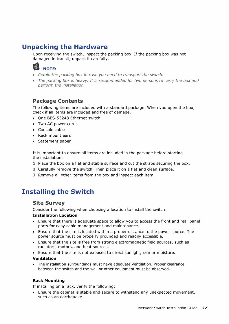
14 Secure the switch to the rack using the screws.
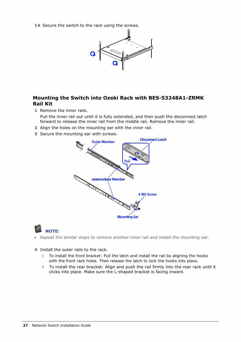
Mounting the Switch into Ozeki Rack with BES-53248A1-ZRMK Rail Kit 1 Remove the inner rails.
Pull the inner rail out until it is fully extended, and then push the disconnect latch forward to release the inner rail from the middle rail. Remove the inner rail.
2 Align the holes on the mounting ear with the inner rail. 3 Secure the mounting ear with screws.
NOTE: • Repeat the similar steps to remove another inner rail and install the mounting ear.
4 Install the outer rails to the rack.
√ To install the front bracket: Pull the latch and install the rail by aligning the hooks with the front rack holes. Then release the latch to lock the hooks into place.
√ To install the rear bracket: Align and push the rail firmly into the rear rack until it clicks into place. Make sure the L-shaped bracket is facing inward.
27 Network Switch Installation Guide

Network Switch Installation Guide 28

The switch supports front and rear rail installations. 5 Align the hooks on the switch with the holes in the inner rail, and then slide the inner
rail backward until it is locked in place. 6 Secure the inner rail to the switch with the screws.
Front Installation Rear Installation
NOTE:
• Repeat the similar steps to install another inner rail.
7 Slide the inner rails on the switch into the middle rails and push the switch all the way to the rear of the rack.
8 Secure the switch to the rack using the screws.
Front Installation Rear Installation
NOTE: • Repeat the similar steps to install another inner rail.
29 Network Switch Installation Guide

NOTE: • Push the disconnect latch to release the switch when removing the switch and it is
fully extended.
Connecting to the Console Port The console port is used for setting up and managing the switch via a connection to a console terminal or PC using a terminal emulation program. You can connect the switch to a terminal or PC using the supplied console cable (RJ-45 male to RS-232 female cable) for serial communication. Below is the console cable wiring specification table: RJ-45 Port of DB9 Female Port of Abbreviation Description Switch PC
3 2 RD Received Data
6 3 TD Transmit Data
5 5 GND Ground
Using the console port, you can perform the following: • Configure the switch using the CLI commands • Manage and monitor network activity by Command Line Interface (CLI) management • Manage and monitor network activity by Simple Network Management Protocol
(SNMP) management • Upgrade the firmware
Network Switch Installation Guide 30

To connect to the console, do the following: 1 Connect the RJ-45 connector to the console port ( ) of the switch.
2 Connect the DB9 to a terminal or PC. 3 Manage the switch using the CLI commands (refer to the CLI User Manual for
more information). The switch uses the following default settings: √ Baud rate: 115200 √ Data width: 8 bits √ Parity: None √ Stop bits: 1 √ Flow control: None
Connecting to the Management Port The management port is a dedicated port interface which is segregated from data traffic crossing other downlink or uplink ports. The port supports auto-negotiation. If the attached device also supports auto-negation, the transmission can operate in either half or full duplex, and data rate can be in 10Mbps, 100Mbps, or 1Gbps. Telnet, SNMP, and Web browser utility can all go through this port for local or remote management after the IP address, subnet mask, and default gateway are properly configured.
CAUTION
• To avoid an IP address conflict, make sure to complete the initial configuration (see “Connecting to the Console Port”) before connecting the management port to the network. For more information on how to configure the switch, refer to the CLI User Manual.
To connect to the management port, do the following: 1 Connect one end of an Ethernet cable to the management port ( ) of the switch.
2 Connect the other end of the Ethernet cable to a network. The Management port LED (Link/Activity LED) lights green when the network link is established.
31 Network Switch Installation Guide

Connecting the Power
CAUTION • Ensure that the socket outlet is installed near the equipment and be easily
accessible. • The power cord must have safety ground pin or contact that is suitable for
the electrical outlet. • The power supply cord(s) must be plugged into socket outlet(s) that
is/are provided with a suitable earth ground.
AC Power Supply The switch is equipped with two slots for power supplies. Depending on your needs, you may opt to use one or both PSUs at a time. Two circuits provide redundancy protection.
NOTE:
• Each PSU has an AC power connector. • At least one power supply must connect to a power source.
To connect the switch to a power source, do the following: 1 Connect one end of the AC power cord to an AC power connector.
2 If you want to use two PSUs, connect another strip of AC power cord to the other AC power connector. Otherwise, skip this step.
3 Connect the other end(s) of the AC power cord(s) to the grounded power outlet(s). The switch has no power button. Once an AC power cord is connected to a power outlet, the switch power is turned on. The Power LED lights green. For details, refer to “Understanding the PSU LEDs”.
Network Switch Installation Guide 32

Components Replacement
Troubleshooting Below is a list of the common problems that you may encounter when using the switch. Try to solve these problems with the suggested solutions before calling for service. If problems persist, contact customer support.
Diagnostic Switch Indicator Problem Solution
Power LED is off. The switch does not receive any power. • Check if the AC power cords are connected properly. • Check if the power supply units are completely seated in the chassis. • The power supply unit may be damaged and needs replacement.
A Port LED is off. • Check if the switch and the connected device are powered on. • Check if the connection in both ends are properly connected. • Check if the cable matches the required length and specification. • Check for a defective cable/port module.
PSU 1 & PSU 2 LED is in Possible issues: Red state. • Fan Lock (15 sec.) • OTP: Over Temperature Process • OCP: Over Current Process • OVP: Over Voltage Process • UVP: Under Voltage Process
Fan LED is in Red state. One or more fans have failed.
Power and Cooling Problems If the power indicator does not turn on when the power cord is plugged in, you may have a problem with the power outlet, power cord, or power supply. However, if the unit powers off after running for a while, check for loose power connections, power losses or surges at the power outlet, and verify that the fans on the unit are unobstructed and running prior to shutdown. If you still cannot isolate the problem, then the internal power supply may be defective.
Installation Verify that all system components have been properly installed. If one or more components appear to be malfunctioning (such as the power cord or network cabling), test them in an alternate environment where you are sure that all the other components are functioning properly.
33 Network Switch Installation Guide

In-Band Access You can access the management agent in the switch from anywhere within the attached network using Telnet, a Web browser, or other network management software tools. However, you must first configure the switch with a valid IP address, subnet mask, and default gateway. If you have trouble establishing a link to the management agent, check to see if you have a valid network connection. Then verify that you entered the correct IP address. Also, be sure the port through which you are connecting to the switch has not been disabled. If it has not been disabled, then check the network cabling that runs between your remote location and the switch.
Replacing the Power Supply
CAUTION • When installing a new PSU, make sure it has the same airflow direction as
the fan modules and the other power supply. • For switches that only using a single power supply, removing the power
supply will cause the switch to automatically shutdown.
The PSUs can be replaced without the use of special tools. Before replacing any of the PSUs, verify the status of the PSU to determine if there is a need for replacement.
NOTE:
• In the event of a power supply failure, you can replace the defective unit without powering down the system, provided that there is at least one power supply must connect to a power source.
To replace the power supply unit, do the following: 1 Disconnect the AC power cord of the PSU that you want to remove. 2 Press the plug retainer and then pull the handle to slide the PSU away from the
chassis.
NOTE: • Take note of the part number of the removed PSU. • When making order for replacement modules, make sure that the part number of the
new PSU is the same as the part number of the removed PSU.
3 Ensure the power supply unit is correctly oriented, then install the new PSU into the chassis until it is firmly seated.
4 Connect the AC power cord to power on the switch.
Network Switch Installation Guide 34

Replacing the Fan Tray
CAUTION • When installing a new fan module, make sure it has the same airflow direction
as the fan modules and the power supply.
The fan modules can be replaced without the use of special tools. Before replacing any of the fan modules, verify the status of the fan modules to determine if there is a need for replacement.
NOTE:
• In the event of a fan failure, make sure to replace it within two minutes.
To replace the fan module, do the following: 1 Press the handle retainer and pull by the handle to slide the fan module away from the
chassis.
NOTE: • Take note of the part number of the removed fan module. • When making order for replacement modules, make sure that the part number of the
new fan module is the same as the part number of the removed fan module.
2 Ensure the fan module is correctly oriented, then install the new fan module into the chassis until it is firmly seated.
Customer Support
WARNING There are no user-serviceable parts inside the PSU or hot-swappable fan module. Do not disassemble any part of the PSU or hot-swappable fan module. Doing so voids the warranty and regulatory certifications.
For maintenance services not mentioned in this guide, please contact the manufacturer’s customer support number as indicated on the warranty card.
35 Network Switch Installation Guide

Refer to the Interoperability Matrix Tool (IMT) on the NetApp Support site to validate that the exact product and feature versions described in this document are supported for your specific environment. The NetApp IMT defines the product components and versions that can be used to construct configurations that are supported by NetApp. Specific results depend on each customer’s installation in accordance with published specifications.
Copyright Information Copyright © 2021 NetApp, Inc. All Rights Reserved. Printed in the U.S. No part of this document covered by copyright may be reproduced in any form or by any means—graphic, electronic, or mechanical, including photocopying, recording, taping, or storage in an electronic retrieval system—without prior written permission of the copyright owner.
Software derived from copyrighted NetApp material is subject to the following license and disclaimer:
THIS SOFTWARE IS PROVIDED BY NETAPP “AS IS” AND WITHOUT ANY EXPRESS OR IMPLIED WARRANTIES, INCLUDING, BUT NOT LIMITED TO, THE IMPLIED WARRANTIES OF MERCHANTABILITY AND FITNESS FOR A PARTICULAR PURPOSE, WHICH ARE HEREBY DISCLAIMED. IN NO EVENT SHALL NETAPP BE LIABLE FOR ANY DIRECT, INDIRECT, INCIDENTAL, SPECIAL, EXEMPLARY, OR CONSEQUENTIAL DAMAGES (INCLUDING, BUT NOT LIMITED TO, PROCUREMENT OF SUBSTITUTE GOODS OR SERVICES; LOSS OF USE, DATA, OR PROFITS; OR BUSINESS INTERRUPTION) HOWEVER CAUSED AND ON ANY THEORY OF LIABILITY, WHETHER IN CONTRACT, STRICT LIABILITY, OR TORT (INCLUDING NEGLIGENCE OR OTHERWISE) ARISING IN ANY WAY OUT OF THE USE OF THIS SOFTWARE, EVEN IF ADVISED OF THE POSSIBILITY OF SUCH DAMAGE.
NetApp reserves the right to change any products described herein at any time, and without notice. NetApp assumes no responsibility or liability arising from the use of products described herein, except as expressly agreed to in writing by NetApp. The use or purchase of this product does not convey a license under any patent rights, trademark rights, or any other intellectual property rights of NetApp.
The product described in this manual may be protected by one or more U.S. patents, foreign patents, or pending applications.
Data contained herein pertains to a commercial item (as defined in FAR 2.101) and is proprietary to NetApp, Inc. The U.S. Government has a non-exclusive, non-transferrable, non-sublicensable, worldwide, limited irrevocable license to use the Data only in connection with and in support of the U.S. Government contract under which the Data was delivered. Except as provided herein, the Data may not be used, disclosed, reproduced, modified, performed, or displayed without the prior written approval of NetApp, Inc. United States Government license rights for the Department of Defense are limited to those rights identified in DFARS clause 252.227-7015(b).
Trademark Information NETAPP, the NETAPP logo, and the marks listed at http://www.netapp.com/TM are trademarks of NetApp, Inc. Other company and product names may be trademarks of their respective owners.