BrM Bridge Insp User Manual-2018 - okladot.state.ok.us Bridge Insp User Manual...Project Information...
93
BRM BRIDGE INSPECTION USER MANUAL FOR OKLAHOMA BRIDGES OKLAHOMA DEPARTMENT OF TRANSPORTATION BRIDGE DIVISION MAY 2018 EDITION
Transcript of BrM Bridge Insp User Manual-2018 - okladot.state.ok.us Bridge Insp User Manual...Project Information...

BRM BRIDGE INSPECTION
USER MANUAL FOR
OKLAHOMA BRIDGES
OKLAHOMA DEPARTMENT OF TRANSPORTATION BRIDGE DIVISION
MAY 2018 EDITION

This BRM Bridge Inspection User Manual consists of pages extracted from the BRM User Manual produced by Bentley. These pages show the various screens and data entry fields most applicable to bridge inspection data entry.

Version 5.3
Prepared for Prepared by A M E R I C A N A S S O C I A T I O N
of S T A T E H I G H W A Y and
T R A N S P O R T A T I O N O F F I C I A L S
AASHTO 444 North Capitol Street
N.W.. Suite 249 Washington. D.C. 20001
685 Stockton Drive Exton. PA 19341

Table of Contents System Basics 11
Logging In 12
BrM Navigation 13
User Profile 15
Message Containers 16
Bridges 17
View List 18
Manage Layouts 24
Manage Filters 27
Edit Filter 27
New Inspection 33
Suff Rate 35
Validate 37
Mapping 49
Reports 51
Generate 52
Inspection 223
Condition 224
Appraisal 235
Inventory 244
Admin 244
Design 249
Roads 253
Agency Bridge Items 260
Schedule 262
Work 267
Work Candidates 267
Project Information 272
Assessments 279
Element Condition Ratings 284
Gateway 306
Export 307
Import 309
Check Out 310
Check In 311
Override 312

- The System Basics section of the manual describes the process of logging in to BrM and explains BrM's layout and navigation.
System Basics

- 12 -
In order to log in to your agency's BrM software, your system administrator must first:
l Set up the ODBC profiles for the BrM databases you will be using. l Establish user names, passwords, and user privileges for each database.
*Note: The standard installation of BrM with the SQL Server sample databases sets up default profiles with a user under the user name and password "pontis."
1. Select the BrM software from the Window applications.
2. Select the desired database from the Database dropdown. This dropdown is only displayed if your agency has more than one database defined in BrM.
3. Enter your login credentials. 4. Click the Login button.
*Note: Contact your administrator if you consistently receive a database error.
Logging In
- 13 -
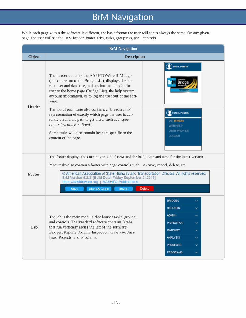
While each page within the software is different, the basic format the user will see is always the same. On any given page, the user will see the BrM header, footer, tabs, tasks, groupings, and controls.
BrM Navigation
Object Description
Header
The header contains the AASHTOWare BrM logo (click to return to the Bridge List), displays the cur- rent user and database, and has buttons to take the user to the home page (Bridge List), the help system, account information, or to log the user out of the soft- ware.
The top of each page also contains a "breadcrumb" representation of exactly which page the user is cur- rently on and the path to get there, such as Inspec- tion > Inventory > Roads.
Some tasks will also contain headers specific to the content of the page.
The footer displays the current version of BrM and the build date and time for the latest version.
Most tasks also contain a footer with page controls such as save, cancel, delete, etc.
Footer
Tab
The tab is the main module that houses tasks, groups, and controls. The standard software contains 8 tabs that run vertically along the left of the software: Bridges, Reports, Admin, Inspection, Gateway, Ana- lysis, Projects, and Programs.
BrM Navigation

- 14 -
Object Description
Task
The tasks make up the menu options for each of the tabs. The tasks run vertically along the left side of the software. Tasks can contain subtasks which are listed underneath the tasks and only visible when the task is selected or expanded.
Grouping
The groupings are the sectioned-off parts of each of the task pages. The groupings typically have dis- play names and their content is often wrapped in a grey outline.
BrM Navigation
The controls are the fields within the groups: checkboxes, text fields, radio buttons, etc.
Control
- 15 -
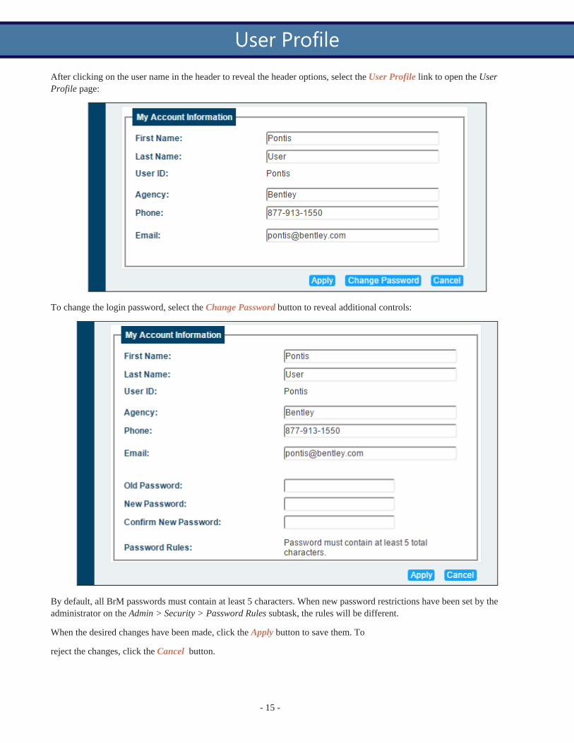
After clicking on the user name in the header to reveal the header options, select the User Profile link to open the User Profile page:
To change the login password, select the Change Password button to reveal additional controls:
By default, all BrM passwords must contain at least 5 characters. When new password restrictions have been set by the administrator on the Admin > Security > Password Rules subtask, the rules will be different.
When the desired changes have been made, click the Apply button to save them. To
reject the changes, click the Cancel button.
User Profile

- 16 -
Message containers are a new feature in BrM version 5.2.3 that display important save, error, or informational messages on specific pages throughout the software. Message containers will typically appear on a page after changes have been made and saved, a save has been attempted, or a required item is not currently completed.
The green message container will appear from the header if the page was saved successfully:
If the page does not save successfully or there is some other message the user needs to see, a message container will appear from the footer:
Message Containers

- The Bridges section of the manual addresses each of the tasks in BrM's Bridges tab. The Bridges tab contains several options to manage the structures within the database.
Bridges
- 18 -
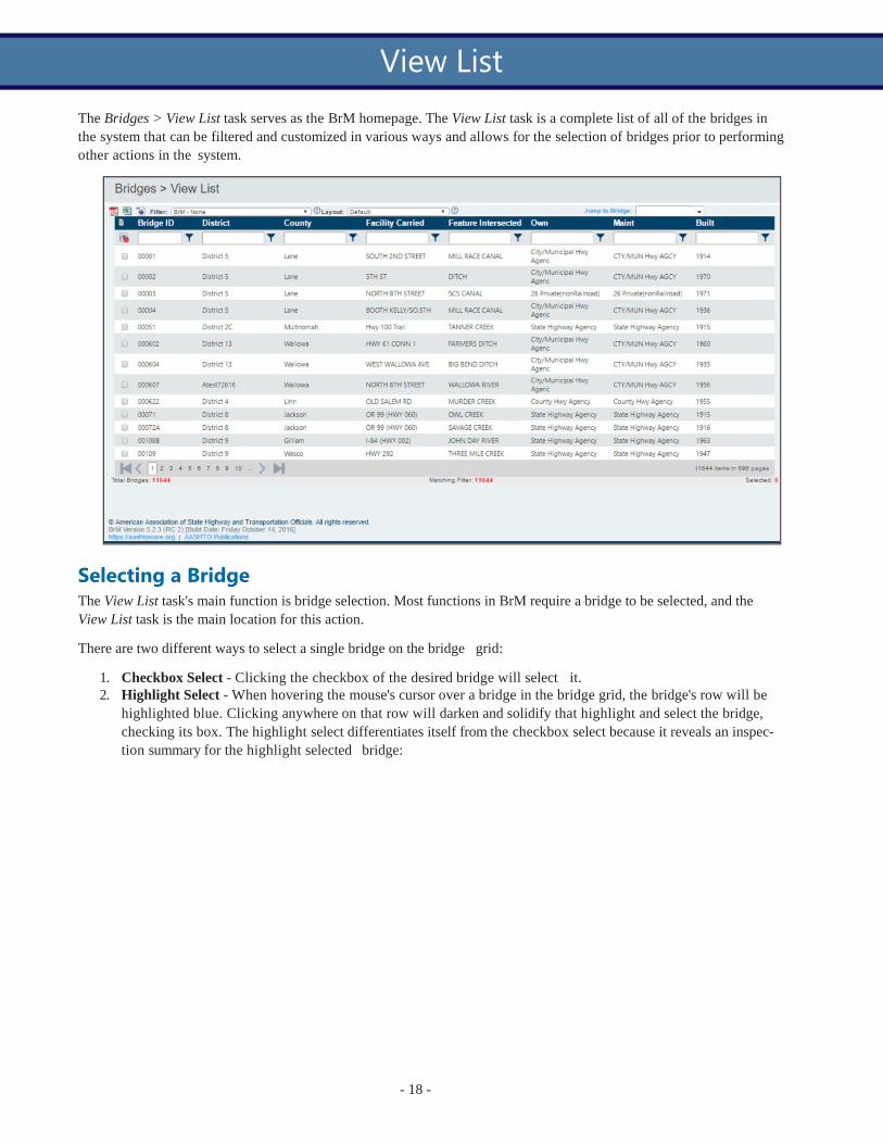
The Bridges > View List task serves as the BrM homepage. The View List task is a complete list of all of the bridges in the system that can be filtered and customized in various ways and allows for the selection of bridges prior to performing other actions in the system.
Selecting a Bridge The View List task's main function is bridge selection. Most functions in BrM require a bridge to be selected, and the View List task is the main location for this action.
There are two different ways to select a single bridge on the bridge grid:
1. Checkbox Select - Clicking the checkbox of the desired bridge will select it. 2. Highlight Select - When hovering the mouse's cursor over a bridge in the bridge grid, the bridge's row will be
highlighted blue. Clicking anywhere on that row will darken and solidify that highlight and select the bridge, checking its box. The highlight select differentiates itself from the checkbox select because it reveals an inspec- tion summary for the highlight selected bridge:
View List

- 19 -
*Note: Regardless of how a bridge is selected, all selected bridges will remain selected until unselected. This is import- ant because many of the functions in BrM take into account all of the currently selected bridges. Users must ensure that before they perform an action, such as generating a report, only the desired bridges are selected.
Highlighted Bridge Images When a bridge is highlighted, the Context dropdown in the Images grouping can be used to determine which images to display. Selecting "Bridge Level" will display the images that have been added to the bridge, not a specific inspection. Selecting a specific inspection will display only the images for that inspection.
Highlighted Bridge Inspection Summary When a bridge is highlighted, the Inspection Summary grouping will display information about the selected bridge's most recent inspection. The various tabs - Condition, Load Rating, Inventory, Roadway On, and Schedule - can be selec- ted to view inspection information.
Filter Due to the vast size of some users' systems, filters are necessary to sort and locate bridges based on specified criteria. Fil- ters are created on the Bridges > Manage Filters and Projects > Manage Filters tasks.
There are two main ways to filter bridges:
1. Filter Dropdown - The Filter dropdown lists all of the relevant filters that have been created and edited on the Manage Filters task. By default, BrM comes with a set of various filters (labeled "BrM" in the dropdown), but new filters can be created. When a filter is selected from the dropdown, the bridge grid will automatically update with the filtered bridges.

- 20 -
2. Quick Filters - Each column in the Bridge List has a quick filter that enables the user to filter the grid based on a
condition. The user types into the Quick Filter textbox and then clicks the symbol to select a condition. Once the condition is selected, the grid will automatically be updated with the filtered bridges.
*Note: By default, filling in the Quick Filter textbox and then pressing Enter on the keyboard will automatically make use of the "Contains" quick filter condition.
The following table explains the various selectable quick filter conditions:
Quick Filter Conditions
Condition Description
NoFilter No filter is applied - filter controls are cleared.
Contains Returns results that contain the entered value. Same as: dataField LIKE '%value%'
DoesNotContain Returns results that do not contain the entered value. Same as dataField NOT LIKE '%value%'
StartsWith Returns results that start with the entered value. Same as: dataField LIKE 'value%'
EndsWith Returns results that end with the entered value. Same as: dataField LIKE '%value'
EqualTo Returns results that exactly match the entered value. Same as: dataField = value
NotEqualTo Returns results that do not exactly match the entered value. Same as: dataField != value
GreaterThan Returns results with a value greater than the entered value. Same as: dataField > value
LessThan Returns results with a value less than the entered value. Same as: dataField < value
GreaterThanOrEqualTo Returns results with a value greater than or exactly matching the entered value.

- 21 -
Quick Filter Conditions
Condition Description
Same as: dataField >= value
LessThanOrEqualTo Returns results with a value less than or exactly matching the entered value. Same as: dataField <= value
Returns results with a value that falls between the two entered values.
Between
NotBetween
Same as: value1 <= dataField <= value2 *Note: Value1 and value2 should be separated by a space when entered into the quick filter.
Returns results with a value that does not fall between the two entered values. Same as: dataField <= value1 & dataField >= value2 *Note: Value1 and value2 should be separated by a space when entered into the quick filter.
IsEmpty Returns results where the specific field is empty. Same as: dataField = ''
NotIsEmpty Returns results where the specific field is not empty. Same as: dataField != ''
IsNull Returns only null values.
NotIsNull Returns only non-null values.
Layout The Layout dropdown determines the bridge grid's columns. There is a default layout on the View List task, but new lay- outs can be created on the Manage Layouts task.
*Note: The Layout dropdown will not be available when certain custom filters (those that are either created or edited using the Manage Filters > Edit SQL subtask) are selected from the Filter dropdown.
Jump to Bridge The Jump to Bridge control allows the user to search for and locate a specific bridge. The user can type the Bridge ID into the textbox or use the dropdown to find the bridge by clicking through the pages.
When typing into the textbox, the search will operate using either the "Contains" or "Starts With" function. The function used is determined by the BRIDGE_SELECTOR_SEARCH_TYPE option on the Admin > General Config > Options task.

- 22 -
When the bridge is selected, it will be highlighted and selected.
Export Options There are three export options located at the top left corner of the bridge grid: Adobe Acrobat Portable Document Format (PDF), Microsoft Excel Spreadsheet (XLS), and Google Keyhole Markup Language (KML). If one or more bridges are selected, only the information from the selected bridges will export. If no bridges are selected, all of the bridges in the current filter will be exported.
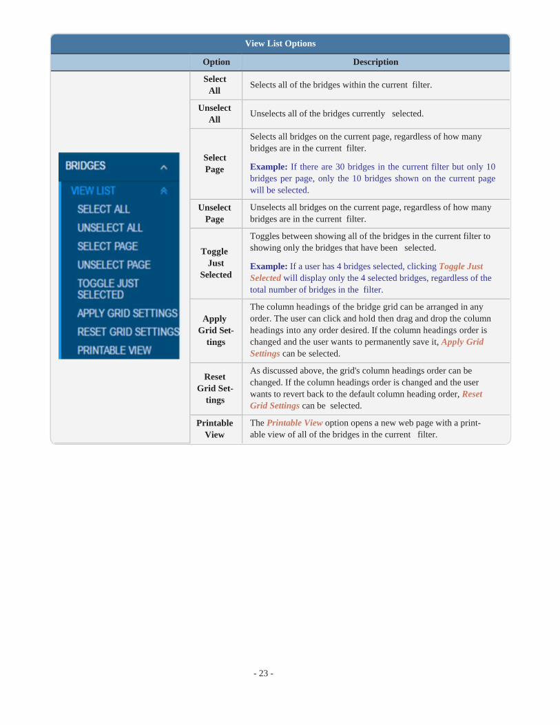
Side Menu Options The side menu for a certain Tab > Task will typically contain subtasks, but for the Bridges > View List task the side menu contains various options that perform actions.
- 23 -
View List Options
Option Description
Select All
Unselect All
Select Page
Unselect
Page
Toggle Just
Selected
Apply Grid Set-
tings
Reset Grid Set-
tings
Printable View
Selects all of the bridges within the current filter.
Unselects all of the bridges currently selected.
Selects all bridges on the current page, regardless of how many bridges are in the current filter.
Example: If there are 30 bridges in the current filter but only 10 bridges per page, only the 10 bridges shown on the current page will be selected.
Unselects all bridges on the current page, regardless of how many bridges are in the current filter.
Toggles between showing all of the bridges in the current filter to showing only the bridges that have been selected.
Example: If a user has 4 bridges selected, clicking Toggle Just Selected will display only the 4 selected bridges, regardless of the total number of bridges in the filter.
The column headings of the bridge grid can be arranged in any order. The user can click and hold then drag and drop the column headings into any order desired. If the column headings order is changed and the user wants to permanently save it, Apply Grid Settings can be selected.
As discussed above, the grid's column headings order can be changed. If the column headings order is changed and the user wants to revert back to the default column heading order, Reset Grid Settings can be selected.
The Printable View option opens a new web page with a print- able view of all of the bridges in the current filter.

- 24 -
The Bridges > Manage Layouts task allows the user to create and edit layouts for the Bridge List as well as several other grids throughout the software. The selections made for the layout will determine the column headings for a given grid. This task is also accessible from the Projects tab with the same functionality.
Context The Context dropdown determines the grid for which the layout is being created. When the Manage Layouts task is opened from the Bridges tab, the default context will be the Bridge List, however there are several other context selec- tions:
l Bridge Group Roadways - The grid on the Bridges > Manage Bridge Groups > Add/Remove Roadways subtask. l Bridge Groups - The grid on the Bridges > Manage Bridge Groups > Bridge Groups subtask. l Bridge List - The grid on the Bridges > View List task. l Funding - The grid on the Projects > Manage Funding > Funding List subtask. l Needs List - The grid on the Analysis > Work Candidates > Needs List subtask. l Programs - The grid on the Projects > Manage Programs > Program List subtask. l Project Bridge Needs - The Bridge Needs grid on the Projects > Create/Edit Project > Query subtask. l Projects - The grid on the Projects > Project List task. l Tunnels - The grid on the Tunnels > Tunnel List task.
Layout The Layout dropdown lists all of the layouts that have been created or that automatically come with the system. The available options depend on the selection made:
l BrM System Layout - If the layout selected is a BrM system layout, it cannot be edited or deleted. A note will appear in red text under the dropdown indicating that the layout is a BrM system layout and may not be edited:
Manage Layouts

- 25 -
However, the user can copy the BrM system layout's settings by typing a new layout name into the textbox next to the Save As button and then clicking Save As. Once the copy is made, the newly created layout can be edited.
l Non-BrM System Layout - Any layout that, when selected, does not cause the red BrM system layout note to appear can be edited or deleted freely.
l New - Clicking the New button creates a new layout that can be edited or deleted freely. The new layout can be named by entering a name into the textbox next to the Save As button and then clicking Save.
Layout Info The Layout Info grouping allows the user to enter a description of the currently selected layout. The user can also check the Shared checkbox if the layout should be available to other users.
Layout Columns The Layout Columns grouping is where the user configures the selected layout. A selection must be made from the Tables listbox and, based on that selection, the Fields listbox will populate with options.
The options in the Fields listbox will be the column headings for the layout. An option can be added to the layout by selecting it from the Fields listbox and clicking the Add button. The multiple select ability of the CTRL and Shift key- board keys is applicable.
The grid formed from the selection contains the table name, field name, heading text, and:
l Use Parameters - The Use Parameters checkbox indicates whether or not parameters will be used for the selec- ted field. Parameters for the fields are set up in the Admin > General Config > Parameters task and designate text to a specific value.
Example: A parameter may be established for a certain field so that any row within that column with the value "1" would present the text "District 1," any row within that column with the value "2" would present the text "District 2," etc.
l Edit - Clicking the symbol allows the user to edit the heading text and check/uncheck the Use Parameters

- 26 -
checkbox. To save the changes, click the symbol. To cancel changes, click the symbol.
l Delete - Clicking the symbol deletes the field from the layout.
The buttons to the right of the table - Top, Up, Down, Bottom - control the positioning of the fields in the layout. Because tables read left to right, the top field in the layout corresponds to the leftmost column of the table. Once an item is selected, The Top and Bottom buttons move it to the top and bottom of the layout grid, respectively. The Up and Down buttons move the selected item up and down by one increment, respectively.
Manage Layouts Page Controls
The Save button saves the current layout.
The Save As button acts as a copier and copies the current layout's settings into a new layout that uses the name entered into the textbox next to the Save As button.
The Reset button resets any changes that were made to the current layout back to the last save.
The Delete button deletes the current layout.

- 27 -
The Bridges > Manage Filters task allows the user to create and edit filters for the Bridge List as well as several other grids throughout the software. The selections made for the filter will determine the bridges listed in the Bridge List upon filter use. This task is also accessible from the Projects tab with the same functionality.
Edit Filter
The Bridges > Manage Filters > Edit Filter subtask uses the BrM interface to create and edit filters for various grids within the system.
Context The Context dropdown determines the grid for which the filter is being created. When the Manage Filters task is opened from the Bridges tab, the default context will be the Bridge List, however there are several other context selections:
l Bridge Group Roadways - The grid on the Bridges > Manage Bridge Groups > Add/Remove Roadways subtask. l Bridge Groups - The grid on the Bridges > Manage Bridge Groups > Bridge Groups subtask. l Bridge List - The grid on the Bridges > View List task. l Funding - The grid on the Projects > Manage Funding > Funding List subtask. l Needs List - The grid on the Analysis > Work Candidates > Needs List subtask. l Programs - The grid on the Projects > Manage Programs > Program List subtask. l Projects - The grid on the Projects > Project List task. l Tunnels - The grid on the Tunnels > Tunnel List task.
Manage Filters

- 28 -
Filter The Filter dropdown lists all of the filters that have been created by that user, shared with a group they are in, or that automatically come with the system. The context must be selected before the filter because the context determines what filters are available.
Filter Info The Filter Info grouping allows the user to enter a description of the currently selected filter.
The user can also check the Shared checkbox if the filter should be available to all other users. There is also an option to share the filter with certain selected groups.
*Note: Users in the Admin group can see all filters if the Option on Admin > General Config > Options is set to true.
For Example: A filter of all in-service bridges would probably be set to 'Shared' with all users. But a filter for all struc- tures which need their load ratings reviewed might only be shared among the load raters.
If the Access Filter checkbox is checked, the admin can use the current filter as an access filter for specified roles, dis- playing that filter as the users' default filter for the applicable context.
For Example: If, to prevent accidents, a filter is created which limints inspectors from District 1 to only seeing structures from District 1, then that filter would marked here as an access filter. Then on the Admin > General Config > Security > Groups page, it would be available as an option to limit access based on the filter.
If the Active checkbox is turned off, the filter will no longer appear in the dropdowns. This is helpful to keep the list of filters down to just what is commonly used.
*Note: The update scripts can reset changes to the default filters if certain settings are turned on - to prevent update scripts from affecting custom filters, save them as a different name and mark the default filter inactive.
Criteria The Criteria grouping is where the user configures the selected filter. A selection must be made from the Tables listbox and, based on that selection, the Fields listbox will populate with options.

- 29 -
Options can be added to the filter by selecting it from the Fields listbox and clicking the Add Criteria button. Multiple options can be added at once by holding down the CTRL key while selecting all of the desired options, then clicking the Add Criteria button.
Each field added to the filter will have additional options that must be determined.
Clicking the Clear button will clear the filter of all fields that have been added. Clicking the Delete Selected button will clear the filter of only the fields that have the Delete checkbox checked.
Edit Filter Page Controls
The Save button saves the current filter.
The Save As button copies the current filter's settings into a new filter that uses the name entered into the textbox next to the Save As button.
The Reset button resets any changes that were made to the current filter back to the last save.
The Delete button deletes the current filter.

- 33 -
The Bridges > New Inspection task allows the user to enter basic information for a new inspection of the currently selec- ted bridge. If more than one bridge is selected on the Bridge List, the new inspection will be for the bridge selected most recently unless one of the bridges is highlighted.
Create New Inspection Inspection Date The Inspection Date field defaults to the current date. To change the date, enter a new date in the MM/DD/YYYY
format or click the symbol and select a date.
Primary Type The Primary Type dropdown lists the primary type of inspection that will be performed. If a previous inspection was per- formed on the selected bridge, the primary type will automatically populate with the option used in the previous inspec- tion but can be changed if desired.
Inspector The Inspector dropdown will default to the current user. This can be changed, however the users available in the drop- down will depend on user roles and permissions.
Entered By The Entered By dropdown will default to the current user. This can be changed, however the users available in the drop- down will depend on user roles and permissions.
Engineer of Record The user can enter an engineer in the Engineer of Record textbox for internal use. This is an optional field.
New Inspection

- 34 -
Inspection > New Inspection Control Information
If the textbox is left blank, the field will be populated with the engineer of record from the previous inspection on the next page. If the previous inspection did not have an Engineer of Record listed or if no previous inspection exists, the field will be blank on the Inspection > Schedule task.
Types of Inspection Performed The user should check the boxes of the inspections that were performed on the bridge on the selected inspection date. The selected inspections will be assigned the selected inspection date on the Inspection > Schedule task. If necessary, this information can be edited later on the Inspection > Schedule task.
New Inspection Page Controls Click the Create button to create the new inspection and automatically be taken to the Inspection > Schedule task to continue filling out the inspection information.
Click the Cancel button to cancel the new inspection and return to the Bridges > View List task.
_______________________________________________________________________
Control Name Table Name
Column Name
Notes
Bridge inspevnt bridge_gd The ID of the bridge being inspected.
Inspection Date
inspevnt inspdate The date the new inspection is created. By default, this will be the current date.
Primary Type inspevnt insptype The primary type of inspection being performed.
Inspector inspevnt inspusrguid The user performing the inspection.
Entered By inspevnt entered_by_gd The user that enters the inspection into the system.
Engineer of Record
inspevnt engineer_of_
record The engineer of record for the inspection.
Types of Inspection Performed Grouping
Routine inspevnt nbinspdone Checked if a routine inspection was performed.
Element inspevnt elinspdone Checked if an element inspection was performed.
Fracture Crit- ical
inspevnt fcinspdone Checked if a fracture critical inspection was performed.
Underwater inspevnt uwinspdone Checked if an underwater inspection was performed.
Other Special inspevnt osinspdone Checked if an other special inspection was performed.

- 35 -
The Bridges > Suff Rate task is used to view and calculate bridge sufficiency ratings.
Sufficiency Rating Results When the Bridges > Suff Rate task is selected, the sufficiency rating of all of the bridges currently selected on the Bridge List is calculated and displayed. If no bridges are selected, noting will be displayed, so a bridge must be selected from the Bridge List before the Suff Rate task can be viewed.
The Sufficiency Rating grid reveals the bridges' previous ratings and the newly calculated ratings based on the most recent inspection. Yellow highlights in the Sufficiency Rating grid columns reveal changes that have occurred between a bridge's previous and currently calculated ratings.
Sufficiency Rating Page Controls
Show Changes and Export Click the Excel Exporticon to download the current view in an excel file.
Use the Showdropdown to show only the bridges with changes between the previous and currently calculated ratings, or to show only the unchanged structures.
To accept the currently calculated ratings, check the Accept checkboxes for the desired bridges or use the Select Page button to select an entire page of bridges.
Once the desired bridges are selected from the grid, click the Accept Selected button to accept the changes and return to the Bridge List. To accept all of the changes (with or without their Accept checkboxes checked), click the Accept All button.
Click the Cancel button to return to the Bridges > View List task.
Suff Rate

- 36 -
Bridges > Suff Rate Control Information
_______________________________________________________________________
Control Name
Table Name
Column Name Notes
Bridge ID bridge bridge_id One of the structure identifiers used in BrM.
Inspection Date
inspevnt inspdate The bridge's most recent inspection date.
Structure Rating
inspevnt
strrating
NBI Item 67: This is the structural evaluation rating of the bridge. This item is calculated by the specifications used in the NBI Cod- ing Guide.
Deck Geometry
inspevnt
deckgeom
NBI Item 68: The overall rating for deck geometry includes two evaluations: the curb-to-curb or face-to-face of rail bridge width and the minimum vertical clearance over the bridge roadway. When an individual table lists several deck geometry rating codes for the same roadway width under a specific ADT, the lower code is used.
Under Clearance
inspevnt underclr NBI Item 69: This is the underclearance of the bridge. This item is calculated by the specifications used in the NBI Coding Guide.
Suff Prefix inspevnt suff_prefix The sufficiency rating prefix.
Suff Rating inspevnt suff_rate The sufficiency rating of the structure.
SD/FO Status
inspevnt nbi_rating The NBI rating (structurally deficient/functionally obsolete status).
2018 SD Status
inspevnt
nbi_rating_ 2018
The NBI rating (structurally deficient) as calculated according to the FHWA Bridge Performance Measure rule which takes effect in 2018.

- 37 -
The Bridges > Validate task is used to validate the accuracy and acceptability of many of the values recorded for a spe- cific bridge.
Validate Bridges The Bridges > Validate task will display all of the bridges currently selected on the Bridge List. If no bridges are selec- ted, a bridge must be selected from the dropdown before the Validate task can be viewed.
To validate only the bridges currently selected, click the Validate Selected Bridges button. To validate all bridges in the database, click the Validate All Bridges button.
*Note: Validating bridges can take an extended period of time depending on the amount of bridges. Validating an entire system of bridges will likely take 5+ minutes to complete.
Click the Cancel button to return to the Bridge List.
Validation Results Once the bridges are validated, the NBI and NBE validation results can be viewed. Use the NBI Results and NBE Res- ults tabs to switch back and forth.
Validate

- 38 -
To view the validation results, click the checkboxes of the desired bridges in the selected grid (all checkboxes will be checked initially). Any errors for the selected bridge(s) will be revealed in the Validation Results grid.
Severity Once the selected bridges are validated, the results will be labeled as "Fatal" or "Warning."
The buttons for each severity level can be used to filter the validation results.
Export Results
Use the symbols to create a PDF or XLS of the current grid.
- 49 -
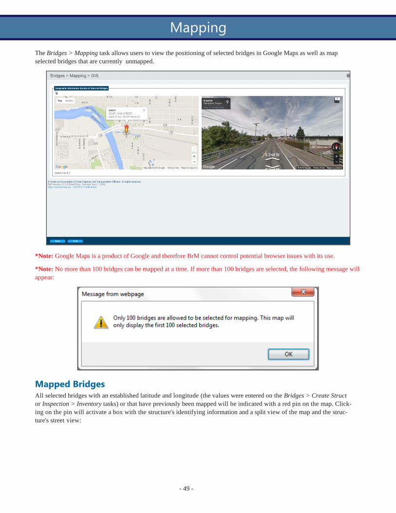
The Bridges > Mapping task allows users to view the positioning of selected bridges in Google Maps as well as map selected bridges that are currently unmapped.
*Note: Google Maps is a product of Google and therefore BrM cannot control potential browser issues with its use.
*Note: No more than 100 bridges can be mapped at a time. If more than 100 bridges are selected, the following message will appear:
Mapped Bridges All selected bridges with an established latitude and longitude (the values were entered on the Bridges > Create Struct or Inspection > Inventory tasks) or that have previously been mapped will be indicated with a red pin on the map. Click- ing on the pin will activate a box with the structure's identifying information and a split view of the map and the struc- ture's street view:
Mapping

- 50 -
Unmapped Bridges
All selected bridges without an established latitude and longitude (the values were not entered on the Bridges > Create Struct or Inspection > Inventory tasks) will appear in a grid in the Unmapped Bridges grouping. The Unmapped Bridges grouping will only appear if a selected bridge is unmapped. Selecting a bridge from the grid in the Unmapped Bridges grouping (clicking on the bridge's row in the grid) changes the map's cursor from a white hand to a black crosshair that, when clicking on the map, pins the unmapped bridge to the map at the selected location. This will then update the bridge's latitude and longitude on the Inspection > Inventory task. Unlike the mapped bridges, this unmapped bridge's pin will be yellow until the Save button is clicked, at which point the pin will turn red. The Update Count number underneath the map will indicate how many map positions have been updated without being saved.
Changing a Mapped Bridge Location To change the map location of a bridge with an established latitude and longitude or previously determined map loc- ation, the user can click and hold the bridge's map pin and then drag and drop it at a new location. As with plotting unmapped bridges, this will change the bridge's pin color to yellow until the Save button is clicked. The Update Count number underneath the map will indicate how many map positions have been updated without being saved.
Sync Mapping Bridges that are plotted via the Bridges > Mapping task and not via the latitude and longitude fields of the Bridges > Create Struct or Inspection > Inventory tasks will not have their latitude and longitudes recorded/updated with the new map plot point.
In order for the latitude and longitude fields (NBI items 016 and 017) to record/update any changes made on the Bridges > Mapping task, the user must use the sync mapping feature of the Admin > Mapping > Sync Mapping task.


- The Reports section of the manual addresses each of the tasks in BrM's Reports tab. The Reports tab allows the user to select, view, and print various reports for all or selected structures in the database.
Reports
- 52 -
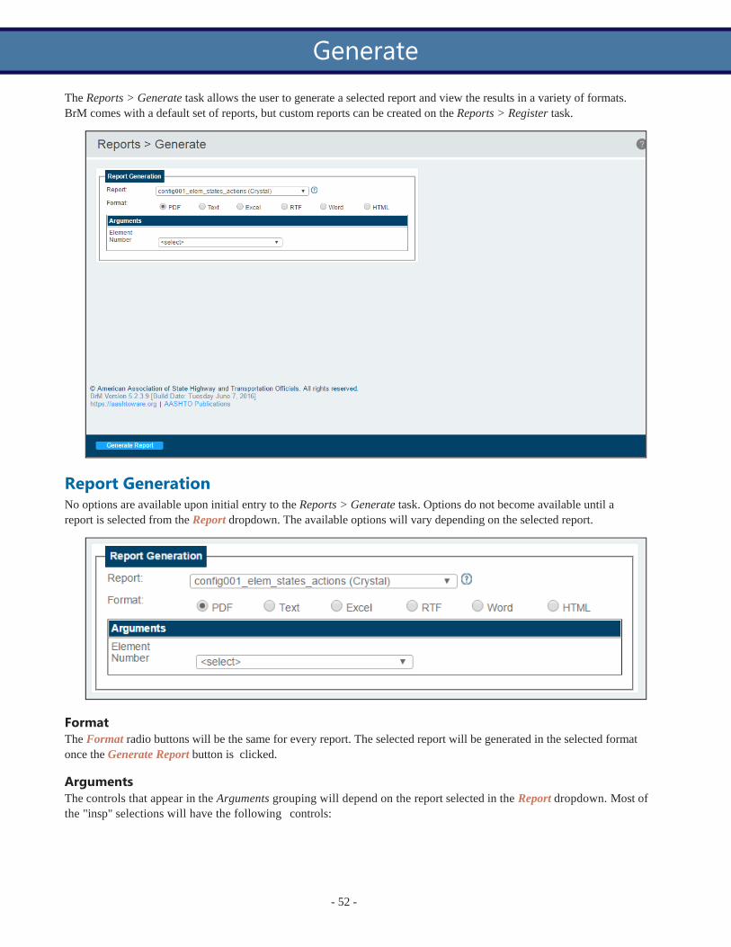
The Reports > Generate task allows the user to generate a selected report and view the results in a variety of formats. BrM comes with a default set of reports, but custom reports can be created on the Reports > Register task.
Report Generation No options are available upon initial entry to the Reports > Generate task. Options do not become available until a report is selected from the Report dropdown. The available options will vary depending on the selected report.
Format The Format radio buttons will be the same for every report. The selected report will be generated in the selected format once the Generate Report button is clicked.
Arguments The controls that appear in the Arguments grouping will depend on the report selected in the Report dropdown. Most of the "insp" selections will have the following controls:
Generate

- 53 -
The radio buttons allow the user to determine exactly which structures to include in the report: all structures, the number of structures in the list, the selected structures, the one highlighted and selected structure (if one is), or a specific struc- ture that can be indicated.
*Note: If the mouse is hovered over the [#] Selected Structures radio button, a tooltip will appear displaying all of the Bridge IDs for the selected structures (up to 200):
Once the desired selections have been made, click the Generate Report button at the bottom of the screen to generate the selected report.
Recently Generated Once at least one report has been generated, the Recently Generated list will appear next to the Report Generation grouping. This provides easy access to reports that were recently generated.
Report Types Below are BrM's default reports and what is included in them:

- 54 -
BrM Default Reports
Report Description
23 Metrics Report v1.4
config001_elem_ states_actions
config002_config_
options_list
config003_para- meter_report
config004_data_dic- tionary
Reviews the selected bridges against the FHWA's list of 23 metrics and determines the level of compliance for each.
The Elements, States & Actions sheet for the selected element.
The User Configuration Options Listing including:
l Configuration options l Option values/default values l Descriptions l Help IDs
The Parameter Report listing all of the parameters the user can modify.
The Pontis Data Dictionary lists and describes all of the columns available for the selec- ted table.
config006_user_list The User List displays all of the system's users including their ID, name, group, role, agency, and phone/email.
config007_misc_sys_ param
The Miscellaneous System Parameters listing.
config008_actions The Actions sheet provides a list of all of the actions in the system that are used for the work candidates as well as in the Analysis and Projects tabs.
config009_ui_nav- igation
config010_app_secur- ity
insp001_inspection_ sia_metric
insp002_inspect_ report_metric
insp003_inspection_ schedule
insp004_inspection_ resource_req
The User Interface Navigation sheet provides a navigation breakdown of every task for the selected tab.
The Application Security report lists all of the selected role's permissions throughout the system.
The Structure Inventory and Appraisal (SI&A) sheet in metric units. It contains:
l All NBI SI&A information l Element-level condition data l Past inspection comments
The expanded SI&A sheet in metric units, including:
l Notes about the bridge, inspection, and each element l Inspector work candidates l Summary information on past inspections
The Inspection Scheduling Information report including:
l Date and inspector for the most recent regular and special inspections l Scheduled frequency of regular and special inspections l Planned dates for the next inspections
The Inspection Resource Requirements report is used to plan resources for new inspec- tions of bridges with special resource requirements. It contains:
l Dates of the previous and next inspections l Hours for crew, flaggers, helpers, snoopers, special crews, and special equipment
insp005_bridge_ The Bridge Health Index Detail sheet displays the health index for the selected bridges

- 55 -
BrM Default Reports
Report Description
health_index_det and provides detailed information about the element condition distributions used to cal- culate the health index.
insp006_network_ elem_sum
insp007_inspection_ sia_english
insp008_inspect_ report_english
insp009_network_ elem_sum_english
insp010_bridge_con-
dition_summary
insp011_inspect_
report_metric
insp012_inspection_ sia_english
insp014_inspect_ report_english
insp015_inspect_ report_metric
insp016_inspect_ report_english
insp017_inspect_ele- ment_report_english
insp018_inspection_ sia_eng (Crystal)
The Network Element Summary Distribution report in metric showing the network-wide distribution of elements by environment and condition state.
The English unit version of insp001_sia_metric.
The English unit version of insp002_inspect_report_metric.
The English unit version of insp006_network_elem_sum.
The Bridge Condition Summary report includes the facility carried, last inspection date, SD/FO status, sufficiency rating, and NBI condition ratings for deck, superstructure, sub- structure, culvert, and channel.
Contains the same data as "insp002_inspect_report_metric" but the element inspection notes do not have their own grid. Instead, they sit below each element in the Element Inspection grid.
Contains only SI&A information and element condition state data in English units.
The expanded SI&A sheet in English units, including:
l Notes about the bridge, inspection, and each element l Inspector work candidates l Summary information on past inspections
Contains the same data as "insp002_inspect_report_metric" as well as a section with any photographs attached to the selected bridge(s).
The English unit version of "insp015_inspect_report_metric."
Contains only a grid for element condition state data in English units.
Similar to the insp016_inspect_report_english report but additionally allows the user to select a specific inspection report if only one structure is selected.
Tunnel report v1 Contain the inventory, inspection, and element data from the last inspection of the selec- ted tunnels.
LRReport Load Rating Report reports all of the load rating summary and history for a selected struc- ture.
OrphanElemntReport A tool for detecting element orphans, identifying what configurations are missing and dia- gnosing other common reasons an element may become orphaned.

- 56 -

- The Inspection section of the manual addresses each of the tasks in BrM's Inspection tab. The Inspection tab allows for the creation and management of inspections, assessments, and more for a selected structure.
Inspection

- 224 -
The Inspection > Condition task allows the user to manage both the NBI condition ratings and the individual element conditions for a specific inspection report.
The Bridge dropdown allows the user to select a bridge to be inspected.
The Inspection dropdown allows the user to select the inspection to be modified.
The Metric/English radio buttons switch between metric and English units on the page.
Condition Ratings The Condition Ratings grouping is used to determine the NBI condition ratings, perform a validation of the selected bridge, and calculate the bridge's sufficiency rating.
There are two ways of setting the bridge's NBI condition ratings. One is to manually complete each of the NBI sub- mission item (NBI numbers are in red parentheses) dropdowns - Deck, Superstructure, Substructure, etc. The other method is to use the NBI Converter Profile as discussed below.
Validate The Validate button takes the user to the Bridges > Validate task to find FHWA discrepancies with the selected bridge.
Condition

- 225 -
Sufficiency Rating The Calculate SR button takes the user to the Bridges > Suff Rate task to calculate the selected bridge's sufficiency rat- ing.
NBI Converter Profile An alternative option to the user manually determining the NBI component ratings is to use the NBI Converter Profile dropdown to estimate the NBI component ratings based on the bridge's element ratings. The NBI Converter Profile drop- down uses the NBI profiles created on the Admin > Modeling Config > NBI Conversion Profiles subtask. Once a selec- tion is made, click the Calculate NBI button to view the results of the calculation:
The table shows the original NBI component ratings (the current ratings) and the converted NBI component ratings. To accept the conversion of any of the NBI components, select the desired components' checkboxes and then click the Accept button. To cancel and not accept any of the conversions, click the Cancel button.
*Note: The NBI Converter Profile dropdown and Calculate NBI button are unavailable when the inspection status is locked, under review, or archived.
Element Conditions The Element Conditions grouping is used to select which elements will be included in the inspection and then determ- ine the condition states of each element.

- 226 -
Search Filters The Hide Elem Inspection Details toggle hides or shows the Notes line on each element as it is selected.
The Element text field is a search bar. As the user starts to type either the element number or the element description, the list of displayed elements will filter down to those which contain that phrase.
The Struct. Unit dropdown is used to select which structure unit's elements to view in the Bridge Elements grid. If "All" is selected, the elements from all of the structure units will be visible in the grid. If a specific structure unit is selected, only that structure unit's elements will be visible. Similarly, the Env. dropdown can be used to filter for a specific envir- onment.
Clicking Clear Filters will display all of the elements and remove any applied filters.
Show Last CoRe Inspection The Show Last CoRe Insp button allows the user to view the last inspection for the selected bridge that used the CoRe inspection that contained a five quantity condition state rating. If an inspection is available, it will appear in a pop-up window and be read-only.
AASHTO Bridge Elements grid The Bridge Elements grid contains all of the elements included in the inspection of the selected bridge (filtered based on structure type with the Select Structure Unit dropdown). For a new structure that has not had a previous inspection there will be no pre-existing elements and all of the desired elements will need to be added. For structures that have pre-exist- ing inspections, the information from the most recent inspection will automatically be loaded into the new inspection.

- 227 -
*Note: By default, the Bridge Elements grid is sorted first by structure unit, then element ID, and finally by environment.
Quantity Columns The Quantity columns can be viewed based on quantity or percent by using the Quantity/Percent radio buttons at the top of the Element Conditions grouping.
The Quantity and condition state Qty. 2, Qty. 3, and Qty. 4 columns can all be modified. The condition state Qty. 1 column cannot be modified. It is updated based on the difference between the Quantity and combined Qty. 2, Qty. 3, and Qty. 4 columns.
If the total quantity is increased, the additional quantity is added to CS1 and the user must manually distribute it amongst the other condition state quantities as needed.
If the total quantity is decreased, none of the condition state quantities will change automatically. The user must manu- ally update the quantities to equal the total quantity.
The user will receive an error when saving if condition state quantities 1-4 do not match the total quantity.
Add Element The Add Element button is available regardless of whether or not an element is selected because it is used to add new NBEs or agency elements to the grid. When clicked, the button reveals the following popup window:

- 228 -
Complete the Element, Structure Unit, and Environment dropdown selections.
*Note: When adding a new element, the Structure Unit dropdown will always default to the agency's default structure unit regardless of what structure unit is selected for the Bridge Elements grid on the Inspection > Condition main page. If the user is expecting the new element to appear in the Bridge Elements grid for the selected structure unit, they must ensure that the selection in the Structure Unit dropdown matches what is selected for the Bridge Elements grid.
Quantity The Quantity field determines the total quantity of the element. This can be changed in the Bridge Elements grid once the element is added.
Add and Cancel Controls Click Add to add the element to the Bridge Elements grid.
Click Cancel to cancel the element addition and return to the Bridge Elements grid.
Add Defect and Protective System The Add Protective System button is symbolized by the green shield and the Add Protective Sys button is symbolized by the orange lightning bolt. Click on them to add them protective systems or defects to this element.
When clicked, the buttons reveal a similar popup to the Add Element button:

- 229 -
Complete the Element dropdown, the Structure Unit and Environment dropdown selections are populated from the par- ent element..
*Note: Only elements that have been linked to the currently selected element in the Admin > Modeling Config > Ele- ment-Child Linking subtask will appear in the Element dropdown.
*Note: Only certain elements will appear in the Parent Element dropdown. In order for an element to appear in the Parent Element dropdown, it must meet the following criteria (the same rules apply for the grandparent > parent rela- tionship):
1. The parent element must be linked to the defect or protective system (as applicable) selected in the Element ID dropdown in the Admin > Modeling Config > Element-Child Linking subtask.
2. The parent element must exist under the selected structure unit. 3. The parent element must exist under the selected environment.
If the desired element does not meet all three qualifications, it will not appear in the Parent Element dropdown. The
remaining selections operate in the same way as the Add New Element button.
Highlighted Orphan A highlighted orphan is a protective system or defect that is displayed in the Bridge Elements grid but is not con- nected to a specific parent element:
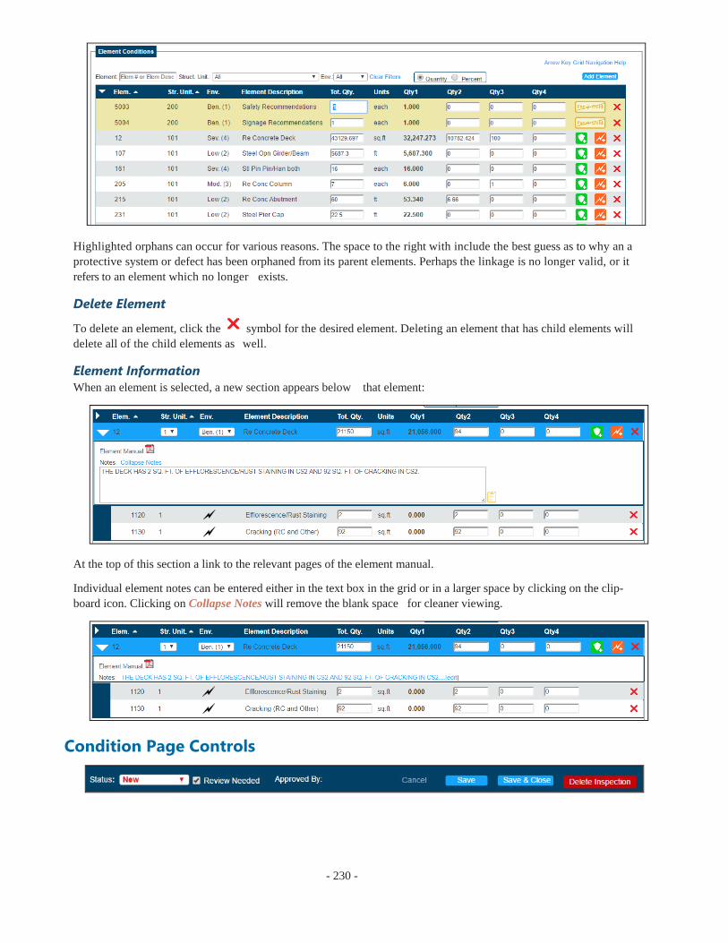
- 230 -
Highlighted orphans can occur for various reasons. The space to the right with include the best guess as to why an a protective system or defect has been orphaned from its parent elements. Perhaps the linkage is no longer valid, or it refers to an element which no longer exists.
Delete Element
To delete an element, click the symbol for the desired element. Deleting an element that has child elements will delete all of the child elements as well.
Element Information When an element is selected, a new section appears below that element:
At the top of this section a link to the relevant pages of the element manual.
Individual element notes can be entered either in the text box in the grid or in a larger space by clicking on the clip- board icon. Clicking on Collapse Notes will remove the blank space for cleaner viewing.
Condition Page Controls

- 231 -
Status The Status dropdown allows the user to change the status of the current inspection report. By default, the available statuses are: New, Under Review, Approved, Locked, and Archived.
Admins can edit these statuses and create new ones by using the inspevnt.inspstat parameter on the Admin > General Config > Parameters task.
*Note: The Status dropdown may be read only for users within certain roles. In order to make the Status dropdown accessible to a specific role, the security must be changed on either the Admin > General Config > Standard or Admin > General Config > Visual Form Editor tasks. It is important to note that a role must have full access to every level of security - tab, task, group, and control - in order to access the Status dropdown. For instance, if a role is given access to the Status dropdown control but the role's access is still set to read only on the entire Inspection > Condition task, that read-only setting for the task will override the access to the control.
Review Needed The Review Needed checkbox allows the user to indicate whether or not the current inspection needs reviewed.
Approved By The Approved By label displays the name of the user who approved the inspection report.
Save/Delete Controls The Save button saves the changes made to the current inspection.
The Save & Close button saves the changes made to the current inspection and returns the user to the Bridges > View List task.
The Cancel button cancels the changes made to the current inspection and returns the user to the Bridges > View List task.
The Delete Inspection button deletes the current inspection for the selected bridge.
_______________________________________________________________________
Status Name Description Approved? *Locked?
New Indicates a newly created inspection record.
No No
Under Review Indicates the inspection record is cur- rently being reviewed.
No Yes
Approved Indicates the inspection record has been given final approval.
Yes No
Locked Indicates the inspection record is locked.
No Yes
Archived Indicates the inspection record is approved and locked.
Yes Yes
Default Statuses
* A locked inspection record means that the Inspection > Condition and Inspection > Schedule tasks are read only for all users.

- 232 -
Inspection > Condition Control Information
Control Name Table Name
Column Name Notes
Condition Ratings Grouping
Deck (58)
inspevnt
dkrating
NBI Item 58 - This item describes the overall condition rating of the deck. Concrete decks should be inspected for cracking, scal- ing, spalling, leaching, chloride contamination, potholing, delamination, and full or partial depth failures. Steel grid decks should be inspected for broken welds, broken grids, section loss, and growth of filled grids from corrosion. Timber decks should be inspected for splitting, crushing, fastener failure, and deteri- oration from rot.
Superstructure
(59)
inspevnt
suprating
NBI Item 59 - This item describes the physical condition of all structural members. The structural members should be inspected for signs of distress which may include cracking, deterioration, section loss, and malfunction and misalignment of bearings.
Substructure (60)
inspevnt
subrating
NBI Item 60 - This item describes the physical condition of piers, abutments, piles, fenders, footings, or other components. All substructure elements should be inspected for visible signs of distress including evidence of cracking, section loss, set- tlement, misalignment, scour, collision damage, and corrosion.
Future Critical Details
bridge
fc_detail
This is an optional non-NBI field used to characterize the frac- ture-critical details on the structure. By definition, fracture crit- ical members are steel elements sustaining tensile stresses whose failure will probably cause a portion of or the entire bridge to collapse. This field will not be used to identify fracture critical bridges - NBI Item 92A can be used for that purpose. This field will be used to identify the reason a bridge is fracture critical as well as identifying fatigue prone details which are not neces- sarily fracture critical.
Channel (61)
inspevnt
chanrating
NBI Item 61 - This item describes the physical conditions asso- ciated with the flow of water through the bridge such as stream stability and the condition of the channel, riprap, slope pro- tection, or stream control devices including spur dikes.
Culvert (62)
inspevnt
culvrating
NBI Item 62 - This item evaluates alignment, settlement, joints, structural condition, scour, and other items associated with cul- verts. The rating code is intended to be overall condition eval- uation of the culvert. Integral wingwalls to first construction or expansion joint shall be included in evaluation. NBI Items 58, 59, and 60 shall be coded N for all culverts.
Waterway (71)
inspevnt
wateradeq
NBI Item 71 - This item appraises the waterway opening with respect to passage of flow through the bridge. Site conditions may warrant somewhat higher or lower ratings.
Unrepaired Spalls
inspevnt deckdistr The actual distressed deck area in square meters. Non-NBI field.
Bridge Elements Grid

- 233 -
Inspection > Condition Control Information
Control Name Table Name
Column Name Notes
Quantity
PON_ ELEM_
INSP
ELEM_ QUANTITY
The total quantity of the selected element.
Qty. 1
PON_ ELEM_
INSP
ELEM_ QTYSTATE1
The quantity of the selected element that is in condition state 1.
Qty. 2
PON_ ELEM_
INSP
ELEM_ QTYSTATE2
The quantity of the selected element that is in condition state 2.
Qty. 3
PON_ ELEM_
INSP
ELEM_ QTYSTATE3
The quantity of the selected element that is in condition state 3.
Qty. 4
PON_ ELEM_
INSP
ELEM_ QTYSTATE4
The quantity of the selected element that is in condition state 4.
Pct. 1
PON_ ELEM_
INSP
ELEM_ PCTSTATE1
The percentage of the selected element that is in condition state 1.
Pct. 2
PON_ ELEM_
INSP
ELEM_ PCTSTATE2
The percentage of the selected element that is in condition state 2.
Pct. 3
PON_ ELEM_
INSP
ELEM_ PCTSTATE3
The percentage of the selected element that is in condition state 3.
Pct. 4
PON_ ELEM_
INSP
ELEM_ PCTSTATE4
The percentage of the selected element that is in condition state 4.
Add Element Popup
The grandparent element exists when there is an element with a protective system and that protective system has a defect. There-
Grandparent Element
PON_
ELEM_ INSP
PARENT_ PON_
ELEM_INSP_ GD
fore, element > protective system > defect.
*Note: While the grandparent is shown, there is no longer a database field for it. So, in the element > protective system > defect family, the grandparent only exists in the database as the
parent of the protective system and not as the grandparent of the defect.
Parent Element PON_
ELEM_ INSP
PARENT_ PON_
ELEM_INSP_ GD
The parent element can be either an element with a protective system or defect, or a protective system in the element > pro- tective system > defect hierarchy.
Element ID PON_
ELEM_ PON_ELEM_
DEFS_GD The element currently selected.

- 234 -
Inspection > Condition Control Information
Control Name Table Name
Column Name Notes
INSP
Structure Unit
PON_ ELEM_
INSP
STRUCTURE_ UNIT_GD
Determines to which structure unit within the bridge that the ele- ment belongs.
Environment
PON_ ELEM_
INSP
PON_ENVT_ DEFS_GD
The environment in which the element exists.
Quantity/Count
PON_ ELEM_
INSP
ELEM_ QUANTITY
The size/amount of the element.
Element Description
PON_ ELEM_
INSP
ELEM_ NOTES
A description or notes about the element.
Inspection Notes Grouping
Insp Level Notes
inspevnt
notes
Notes for the current inspection.
Inspection Header
Bridge bridge bridge_id The agency bridge identification number that is used to identify structures on most screens and reports.
Facility Carried bridge facility NBI Item 7: The facility carried by the structure.
Inspection Date Selection
inspevnt inspkey The inspection key. A unique identifier for the inspections on a particular structure that includes the date of the inspection.
Type inspevnt insptype The primary type of inspection performed.
Inspection Footer
Status inspevnt inspstat The current status of the selected inspection.
Review Needed
inspevnt rev_req Indicates whether or not a review of the inspection is required.
Approved By inspevnt inspname The name of the user that approved the inspection report.

- 235 -
The Inspection > Appraisal task allows the user to enter a bridge's NBI structure appraisal information, including clear- ances, NBI load ratings, and more. The user can also view the calculated appraisal ratings for the selected bridge, oper- ating and inventory ratings, and the structure's posting status.
Appraisal Groupings Structural Appraisal The Structural Appraisal grouping contains several structural NBI fields to be completed.
Calculated Appraisal Ratings The Calculated Appraisal Ratings grouping contains information that is calculated on the database level, including NBI fields such as structural evaluation and sufficiency rating. The Bridges > Suff Rate task can be used to update the cal- culated values in this section.
Appraisal

- 236 -
The Bridge Condition rating is determined by the lowest rating of the NBI condition ratings for deck, superstructure, sub- structure, and culvert. The status is as follows:
l Good - 9, 8, 7 l Fair - 6, 5 l Poor - 4, 3, 2, 1
Example: An inspection is completed with the following values:
Deck: 7 Superstructure: 6 Substructure: 5 Culvert : Null
Because substructure is the lowest NBI condition rating, it will be used to determine the Good/Fair/Poor status. With "5" as its rating, the bridge status will be set to Fair.
Clearances The Clearances grouping contains vertical and lateral clearances and navigation data NBI fields to be completed.
NBI Load Ratings The NBI Load Ratings grouping contains load rating NBI fields and alternate fields to be completed.
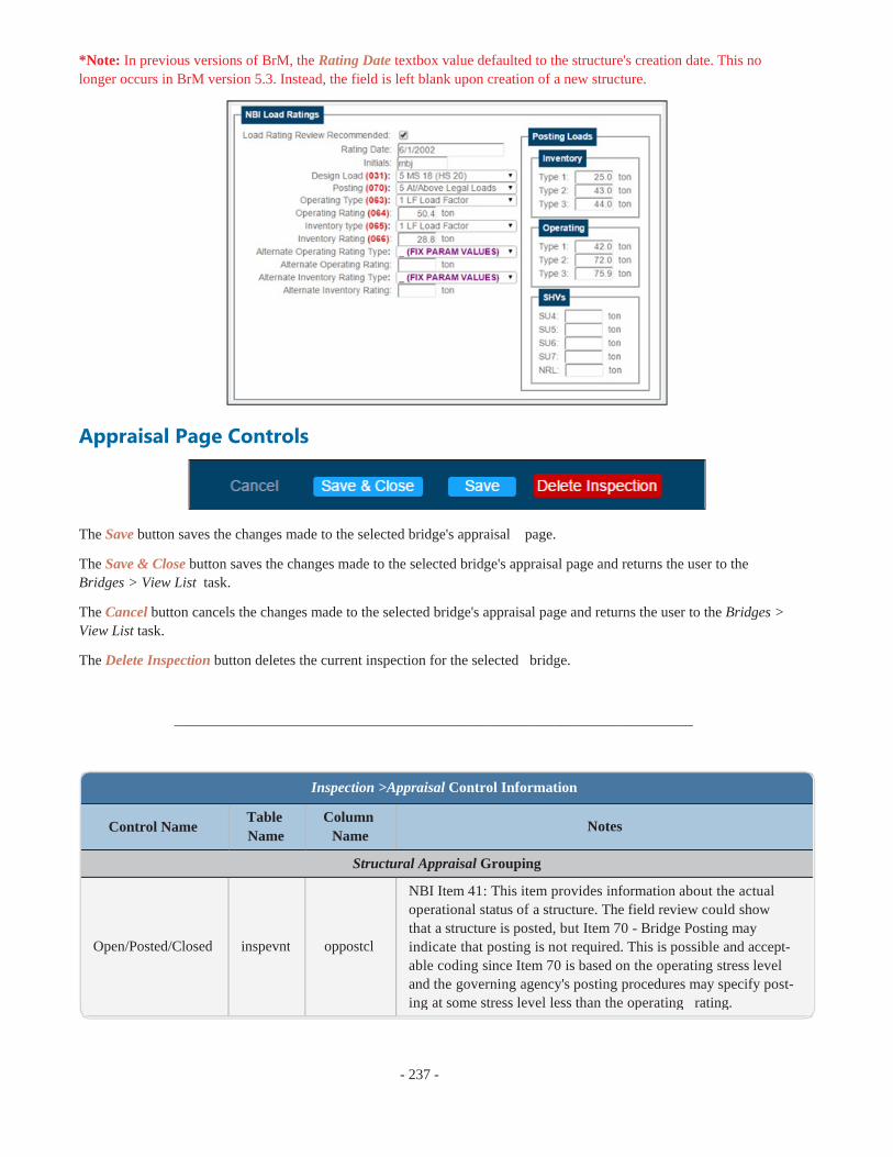
- 237 -
*Note: In previous versions of BrM, the Rating Date textbox value defaulted to the structure's creation date. This no longer occurs in BrM version 5.3. Instead, the field is left blank upon creation of a new structure.
Appraisal Page Controls
The Save button saves the changes made to the selected bridge's appraisal page.
The Save & Close button saves the changes made to the selected bridge's appraisal page and returns the user to the Bridges > View List task.
The Cancel button cancels the changes made to the selected bridge's appraisal page and returns the user to the Bridges > View List task.
The Delete Inspection button deletes the current inspection for the selected bridge.
_______________________________________________________________________
Control Name Table Name
Column Name
Notes
Structural Appraisal Grouping
Inspection >Appraisal Control Information
Open/Posted/Closed inspevnt oppostcl
NBI Item 41: This item provides information about the actual operational status of a structure. The field review could show that a structure is posted, but Item 70 - Bridge Posting may indicate that posting is not required. This is possible and accept- able coding since Item 70 is based on the operating stress level and the governing agency's posting procedures may specify post- ing at some stress level less than the operating rating.

- 238 -
Inspection >Appraisal Control Information
Control Name Table Name
Column Name
Notes
Approach Align- ment
inspevnt
appralign
NBI Item 72: This item identifies those bridges which do not function properly or adequately due to the alignment of the approaches. It is not intended that the approach roadway align- ment be compared to current standards but rather to the existing highway alignment. This concept differs from other appraisal evaluations. The establishment of set criteria to be used at all bridge sites is not appropriate for this item. The basic criteria is how the alignment of the roadway approaches to the bridge relate to the general highway alignment for the section of high- way the bridge is on.
Bridge Railings
inspevnt
railrating
NBI Item 36A: Bridge railings should be evaluated using the current AASHTO Standard Specifications for Highway Bridges, which calls for railings to meet specific geometric criteria and to resist specified static loads without exceeding the allowable stresses in their elements.
Transitions
inspevnt
transratin
NBI Item 36B: The transition from approach guardrail to bridge railing requires that the approach guardrail be firmly attached to the bridge railing. It also requires that the approach guardrail be gradually stiffened as it comes closer to the bridge railing. The ends of curbs and safety walks need to be gradually tapered out or shielded. The data collected shall apply only to the route on the bridge. Collision damage or deterioration of the elements are not considered when coding this item.
Approach Guardrail
inspevnt
arailratin
NBI Item 36C: The structural adequacy and compatibility of approach guardrail with transition designs should be determ- ined. Rarely does the need for a barrier stop at the end of a bridge. Acceptable guardrail design suggestions are contained in the AASHTO Roadside Design Guide and subsequent FHWA or AASHTO guidelines. The data collected shall apply only to the route on the bridge. Collision damage or deterioration of the elements are not considered when coding this item.
Approach Guardrail Ends
inspevnt
aendrating
NBI Item 36D: As with guardrail ends in general, the ends of approach guardrails to bridges should be flared, buried, made breakaway, or shielded. Design treatment of guardrail ends is given in the AASHTO Roadside Design Guide. The data col- lected shall apply only to the route on the bridge. Collision dam- age or deterioration of the elements are not considered when coding this item.
Pier Protection inspevnt pierprot NBI Item 111: Code the whether pier protection is present and the status of the protection.
Scour Critical inspevnt
scrourcrit
NBI Item 113: Identify current status of bridge regarding vul- nerability to scour. Scour analyses to be made by hydraul- ic/geotechnical/structural engineers. A scour critical bridge is one with abutment or pier foundations which are rated as unstable due to observed scour at bridge site or scour potential
- 239 -
Control Name
Table Name
Inspection >Appraisal Control Information
Column Name
Notes
Fracture Critical Details
inspevnt fc_detail
as determined from scour evaluation study.
This is an optional non-NBI field used to characterize the frac- ture-critical details on the structure. This field will not be used to identify fracture critical bridges; NBI Item 92A can be used for that purpose. This field will be used to identify the reason a bridge is fracture critical as well as identifying fatigue prone details which are not necessarily fracture critical.
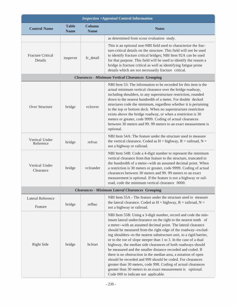
Clearances - Minimum Vertical Clearances Grouping
NBI Item 53: The information to be recorded for this item is the actual minimum vertical clearance over the bridge roadway, including shoulders, to any superstructure restriction, rounded down to the nearest hundredth of a meter. For double decked
Over Structure bridge vclrover
Vertical Under bridge refvuc Reference
Vertical Under bridge vclrunder
Clearance
structures code the minimum, regardless whether it is pertaining to the top or bottom deck. When no superstructure restriction exists above the bridge roadway, or when a restriction is 30 meters or greater, code 9999. Coding of actual clearances between 30 meters and 99. 99 meters to an exact measurement is optional.
NBI Item 54A: The feature under the structure used to measure the vertical clearance. Coded as H = highway, R = railroad, N = not a highway or railroad.
NBI Item 54B: Code a 4-digit number to represent the minimum vertical clearance from that feature to the structure, truncated to the hundredth of a meter--with an assumed decimal point. When a restriction is 30 meters or greater, code 9999. Coding of actual clearances between 30 meters and 99. 99 meters to an exact measurement is optional. If the feature is not a highway or rail- road, code the minimum vertical clearance 0000.
Lateral Reference
Clearances - Minimum Lateral Clearances Grouping
NBI Item 55A - The feature under the structure used to measure
Feature bridge refhuc the lateral clearance. Coded as H = highway, R = railroad, N =
not a highway or railroad.
Right Side bridge hclrurt
NBI Item 55B: Using a 3-digit number, record and code the min- imum lateral underclearance on the right to the nearest tenth of a meter--with an assumed decimal point. The lateral clearance should be measured from the right edge of the roadway--exclud- ing shoulders--to the nearest substructure unit, to a rigid barrier, or to the toe of slope steeper than 1 to 3. In the case of a dual highway, the median side clearances of both roadways should be measured and the smaller distance recorded and coded. If there is no obstruction in the median area, a notation of open should be recorded and 999 should be coded. For clearances greater than 30 meters, code 998. Coding of actual clearances greater than 30 meters to an exact measurement is optional. Code 000 to indicate not applicable.

- 240 -
Inspection >Appraisal Control Information
Control Name Table Name
Column Name
Notes
Left Side
bridge
hclrult
NBI Item 56: Using a 3-digit number, record and code the min- imum lateral underclearance on the left--median side for divided highways--to the nearest tenth of a meter--with an assumed decimal point. The lateral clearance should be measured from the left edge of the roadway--excluding shoulders--to the nearest substructure unit, to a rigid barrier, or to the toe of slope steeper than 1 to 3. In the case of a dual highway, the median side clear- ances of both roadways should be measured and the smaller dis- tance recorded and coded. If there is no obstruction in the median area, a notation of open should be recorded and 999 should be coded. For clearances greater than 30 meters, code 998. Coding of actual clearances greater than 30 meters to an exact measurement is optional. Code 000 to indicate not applic- able.
Navigation Data Grouping
Navigation Control Exists
bridge navcntrol NBI Item 38: Indicates whether or not a bridge permit is neces- sary for navigation, if applicable.
Navigation Vertical Clearances
bridge navvc NBI Item 39: If navigation of the waterway requires a permit, this is the minimum vertical clearance of the navigation.
Navigation Hori- zontal Clearances
bridge navhc NBI Item 40: If navigation of the waterway requires a permit, this is the minimum horizontal clearance of the navigation.
Navigation Vertical Lift Clearances
bridge lftbrnavcl NBI Item 116: The minimum vertical lift clearance for the lift bridge in the dropped/closed position.
Calculated Appraisal Ratings Grouping
Structural Evalu- ation
inspevnt
strrating
NBI Item 67: This is the structural evaluation rating of the bridge. This item is calculated by the specifications used in the NBI Coding Guide.
Deck Geometry
inspevnt
deckgeom
NBI Item 68: The overall rating for deck geometry includes two evaluations: the curb-to-curb or face-to-face of rail bridge width and the minimum vertical clearance over the bridge roadway. When an individual table lists several deck geometry rating codes for the same roadway width under a specific ADT, the lower code is used.
Underclearances
inspevnt
underclr
NBI Item 69: This is the underclearance of the bridge. This item is calculated by the specifications used in the NBI Coding Guide.
SD/FO Status inspevnt nbi_rating The NBI rating (structurally deficient/functionally obsolete status).
2018 SD inspevnt nbi_rat-
ing_2018 Structural deficiency status complying with the FHWA per- formance management rule effective Jan 1st, 2018.
Sufficiency Rating inspevnt suff_rate The calculated sufficiency rating of the bridge.
SRCS bridge srstatus Indicates whether the sufficiency rating is current or needs

- 241 -
Inspection >Appraisal Control Information
Control Name Table Name
Column Name
Notes
updated.
Health Index The health index is a calculated value that comes from database
view: v_hix.hix.
NBI Load Ratings Grouping
Load Rating Review Recom-
mended
bridge
req_op_rat
This control indicates whether review of the load ratings is recommended.
Rating Date bridge ratingdate The date the load rating calculation was made. Non-NBI field.
Initials bridge rater_ini The initials of the load rater/engineer responsible for performing the load rating. Non-NBI field.
Design Load
bridge
designload
NBI Item 31: Use the codes below to indicate the live load for which the structure was designed. The numerical value of the railroad loading should be recorded on the form.
Posting
bridge
posting
NBI Item 70: The National Bridge Inspection Standards require the posting of load limits only if the maximum legal load con- figurations in the state exceeds the load permitted under the operating rating. If the load capacity at the operating rating is such that posting is required, this item shall be coded 4 or less. If no posting is required at the operating rating, this item shall be coded 5.
Operating Type
bridge
ortype
NBI Item 63: Use one of the codes below to indicate which load rating method was used to determine the Operating Rating coded in Item 64 for this structure.
Operating Rating
bridge
orload
NBI Item 64: This capacity rating, referred to as the operating rating, will result in the absolute maximum permissible load level to which the structure may be subjected for the vehicle type used in the rating. Code the operating rating as a 3-digit number to represent the total mass in metric tons of the entire vehicle measured to the nearest tenth of a metric ton--with an assumed decimal point. It should be emphasized that only MS loading shall be used to determine the operating rating.
Inventory Type
bridge
irtype
NBI Item 65: Use one of the codes below to indicate which load rating method was used to determine the Inventory Rating coded in Item 66 for this structure.
Inventory Rating bridge
irload
NBI Item 66: This capacity rating, referred to as the inventory rating, will result in a load level which can safely utilize an existing structure for an indefinite period of time. Only the MS loading shall be used to determine the inventory rating. Code the Inventory Rating as a 3-digit number to represent the total mass in metric tons of the entire vehicle measured to the nearest tenth of a metric ton--with an assumed decimal point. Code 999 for a structure under sufficient fill such that, according to AASHTO design, the live load is insignificant in the structure

- 242 -
Control Name
Table Name
Inspection >Appraisal Control Information
Column Name
Notes
Alternate Operating bridge altormeth Rating Type
Alternate Operating bridge altorload Rating
Alternate Inventory bridge altirmeth Rating Type
Alternate Inventory bridge altirload Rating
load capacity.
The alternate operating rating method. Optional non-NBI field to indicate the method used in developing the alternate oper- ating load rating fields.
The alternate operating load rating. Optional non-NBI field to hold a load rating by some alternative method aside from the one used in the NBI load rating fields.
The alternate inventory rating method. Optional non-NBI field to indicate the method used in developing the alternate oper- ating load rating fields.
The alternate inventory load rating. Optional non-NBI field to hold a load rating by some alternative method aside from the one used in the NBI load rating fields.
Posting Loads - Inventory Grouping
The operating rating for truck type 1. This is an optional non- Inventory - Type 1 bridge truck1or
Inventory - Type 2 bridge truck2or
Inventory - Type 3 bridge truck3or
NBI field to provide for a load rating specific to a particular type of truck.
The operating rating for truck type 2. This is an optional non- NBI field to provide for a load rating specific to a particular type of truck.
The operating rating for truck type 3. This is an optional non- NBI field to provide for a load rating specific to a particular type of truck.
Posting Loads - Operating Grouping
Operating - Type 1 bridge truck1ir The inventory rating for truck type 1. Optional non-NBI field to provide for a load rating specific to a particular type of truck.
Operating - Type 2 bridge truck2ir The inventory rating for truck type 2. Optional non-NBI field to provide for a load rating specific to a particular type of truck.
Operating - Type 3 bridge truck3ir The inventory rating for truck type 3. Optional non-NBI field to provide for a load rating specific to a particular type of truck.
Posting Loads - SHVs Grouping
SU4 bridge su4 Single unit SHV load model - 4 axle SHV.
SU5 bridge su5 Single unit SHV load model - 5 axle SHV.
SU6 bridge su6 Single unit SHV load model - 6 axle SHV.
SU7 bridge su7 Single unit SHV load model - 7 axle SHV.
NRL bridge nrl Notational rating load model.
Inspection Header
Bridge bridge bridge_id The agency bridge identification number that is used to identify structures on most screens and reports.

- 243 -
Inspection >Appraisal Control Information
Control Name Table Name
bridge
Column Name
facility
Notes
Facility Carried
Inspection Date Selection
Type
inspevnt inspkey
inspevnt insptype
Status
Review Needed
Approved By
inspevnt
inspevnt
inspevnt
NBI Item 7: The facility carried by the structure.
The inspection key. A unique identifier for the inspections on a particular structure that includes the date of the inspection.
The primary type of inspection performed.
Inspection Footer
inspstat The current status of the selected inspection.
rev_req Indicates whether or not a review of the inspection is required.
inspname The name of the user that approved the inspection report.
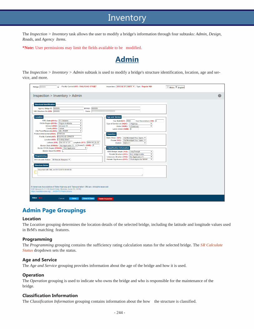
The Inspection > Inventory task allows the user to modify a bridge's information through four subtasks: Admin, Design, Roads, and Agency Items.
*Note: User permissions may limit the fields available to be modified.
Admin
The Inspection > Inventory > Admin subtask is used to modify a bridge's structure identification, location, age and ser- vice, and more.
Admin Page Groupings Location The Location grouping determines the location details of the selected bridge, including the latitude and longitude values used in BrM's matching features.
Programming The Programming grouping contains the sufficiency rating calculation status for the selected bridge. The SR Calculate Status dropdown sets the status.
Age and Service The Age and Service grouping provides information about the age of the bridge and how it is used.
Operation The Operation grouping is used to indicate who owns the bridge and who is responsible for the maintenance of the bridge.
Classification Information The Classification Information grouping contains information about the how the structure is classified.
- 244 -
Inventory

- 245 -
Inspection > Inventory > Admin Control Information
Admin Page Controls If changes have been made to the subtask, those changes must be saved before leaving the current page in order for the changes to be maintained.
The Save button saves the changes made on the current subtask.
The Save & Close button saves the changes made on the current subtask and returns the user to the Bridges > View List task.
The Cancel button cancels the changes made on the current subtask and returns the user to the Bridges > View List task. The
Delete Inspection button deletes the current inspection for the selected bridge.
_______________________________________________________________________
Control Name Table Name
Column Name
Notes
Structural Identification Grouping
Agency Bridge ID bridge bridge_id Agency bridge identification number. Used to identify struc- tures on most screens and reports.
NBI Structure No.
bridge
struct_num
NBI Item 8 - The NBI structure number. Note that regardless of whether Item 8 is mapped only to struct_num or also to additional fields, if a user changes the value stored and exports then imports an NBI file, the result may be the cre- ation of a new brkey.
Brkey bridge brkey The bridge key. One of the structure identifiers in BrM.
Name bridge strucname The agency's structure name. Non-NBI field.
Location Grouping
FIPS State bridge fips_state NBI Item 1A - The state the structure is located within.
FHWA Region bridge fhwa_regn NBI Item 1B - The region the structure is located within.
District
bridge
district
NBI Item 2 - The highway agency district in which the bridge is located. Existing district numbers shall be used where districts are identified by number. Where districts are identified by name, a code number shall be assigned based on an alphabetical or organizational listing of the districts.
County bridge county NBI Item 3 - The county the structure is located within.
City/Town/Placecode bridge placecode NBI Item 4 - The city, town, township, village, or other census-designated place the structure is located within.
Feature Intersected bridge featint NBI Item 6 - This item contains a description of the features intersected by the structure and a critical facility indicator.

- 246 -
Inspection > Inventory > Admin Control Information
Control Name Table Name
Column Name
Notes
When Item 5A indicates an under record, this item describes the inventory route and/or features under the structure.
Facility Carried
bridge
facility
NBI Item 7 - The facility being carried by the structure shall be recorded and coded. In all situations this item describes the use on the structure.
Location
bridge
location
NBI Item 9 - This item contains a narrative description of the bridge location. It is recommended that the location be keyed to a distinguishable feature on an official highway department map such as road junctions and topographical features.
Latitude
bridge
latitude
NBI Item 16 - For bridges on STRAHNET and STRAHNET Connector highways and on the NHS, record and code the latitude of each in degrees, minutes and seconds to the nearest hundredth of a second--with an assumed decimal point. The point of the coordinate may be the beginning of the bridge in the direction of the inventory or any other con- sistent point of reference on the bridge which is compatible with the LRS.
Longitude
bridge
longitude
NBI Item 17 - For bridges on STRAHNET and STRAHNET Connector highways and on the NHS, record and code the longitude of each in degrees, minutes and seconds to the nearest hundredth of a second--with an assumed decimal point. The point of the coordinate may be the beginning of the bridge in the direction of the inventory or any other con- sistent point of reference on the bridge which is compatible with the LRS.
Border State
bridge
nstatecode
NBI Item 98AA - The neighboring state of the structure. For the special case of a structure on the border with Canada or Mexico, code the State code "CAN" or "MEX" respectively. If structure is not on a border, leave blank.
Share%
bridge
bb_pct
NBI Item 98B - It is for specifying the percent responsibility for improvements to the existing structure when it is on a border with a neighboring state. Code it with the percentage of total deck area of the existing bridge that the neighboring state is responsible for funding.
Border FHWA Region
bridge
n_fhwa_reg
NBI Item 98AB - Indicate the FHWA region of the neigh- boring state. For the special case of a structure on the border with Canada or Mexico, leave blank.
Border Struct No. bridge
bb_brdgeid
NBI Item 99 - Code the neighboring state's 15-digit NBI structure number for any structure noted in Item 98. This number must match exactly the neighboring state's sub- mitted NBI structure number. The entire 15-digit field must be accounted for including zeros and blank spaces whether they are leading, trailing, or embedded in the 15-digit field. If Item 98 is blank, this item is blank.

- 247 -
Inspection > Inventory > Admin Control Information
Control Name Table Name
Column Name
Programming Grouping
Notes
SR Calculate Status bridge srstatus
Tracks whether sufficiency rating (SR) needs to be recal- culated. This field is set to 1 when a new roadway or inspec- tion is created (and in response to other circumstances that may trigger a need to recalculate SR), and set to 0 when SR is recalculated.
Age and Service Grouping
NBI Item 27 - Record and code the year of construction of
Year Built bridge yearbuilt
Year Reconstruct bridge yearrecon
the structure. Code all 4 digits of the year in which con- struction of the structure was completed. If the year built is unknown, provide a best estimate.
NBI Item 106 - Record and code the year of most recent reconstruction of the structure. Code all 4 digits of the latest year in which reconstruction of the structure was completed. If there has been no reconstruction code 0000.
Type of Service On bridge servtypon NBI Item 42A - Indicates the type of service on the bridge.
Under bridge servtypund NBI Item 42B - Indicates the type of service under the bridge.
Lane Under bridge sumlanes NBI Item 28B - The sum of the number of lanes under the structure.
Operation Grouping
Maintenance Resp. bridge custodian NBI Item 21 - The name of the agency responsible for the maintenance of the structure.
Owner bridge owner NBI Item 22 - The name of the owner of the structure.
Agency Admin Area bridge adminarea This is used in subsetting and sorting of bridge data as a convenience feature. Non-NBI field.
Specifies whether the structure is on or off the agency sys-
On/Off Agency Sys- bridge on_off_sys tem
Bridge Group bridge bridgegroup
tem. Typically based on the value for either structure own- ership (NBI Item 22) or custodian (NBI Item 21). Used for determining applicable policies and costs, and for reporting results.
Agency-defined group for the bridge. Intended for use in grouping together bridges for inspection purposes. Non-NBI field.
Classification Information Grouping
NBI Item 112 - Indicate whether this structure meets or NBIS Bridge Length bridge nbislen exceeds the minimum length specified to be designated as a
bridge by NBI standards.
Parallel Structure bridge paralstruc
NBI Item 101 - Code this item to indicate situations where separate structures carry the inventory route in opposite dir- ections of travel over the same feature.

- 248 -
Inspection > Inventory > Admin Control Information
Control Name Table Name
Column Name
Notes
Temporary Structure
bridge
tempstruc
NBI Item 103 - Code this item to indicate situations where temporary structures or conditions exist. Temporary struc- tures or conditions are those which are required to facilitate traffic flow. This may occur either before or during the modi- fication or replacement of a structure found to be deficient.
Historic Significance
bridge
histsign
NBI Item 37 - The historical significance of a bridge involves a variety of characteristics: the bridge may be a par- ticularly unique example of the history of engineering; the crossing itself might be significant; the bridge might be asso- ciated with a historical property or area; or historical sig- nificance could be derived from the fact the bridge was associated with significant events or circumstances.
Structure Notes Grouping
Structure Notes bridge notes Notes about the structure.
Inspection Header
Bridge bridge bridge_id The agency bridge identification number that is used to identify structures on most screens and reports.
Facility Carried bridge facility NBI Item 7: The facility carried by the structure.
Inspection Date Selection
inspevnt
inspkey
The inspection key. A unique identifier for the inspections on a particular structure that includes the date of the inspec- tion.
Type inspevnt insptype The primary type of inspection performed.
Inspection Footer
Status inspevnt inspstat The current status of the selected inspection.
Review Needed inspevnt rev_req Indicates whether or not a review of the inspection is required.
Approved By inspevnt inspname The name of the user that approved the inspection report.

- 249 -
Design
The Inspection > Inventory > Design subtask is used to modify a bridge's deck, span, length, and more. New structure units can also be created on this page.
Structure Units The Structure Units grouping allows the user to create/modify structure units. Structure units are groups of structures typ- ically based on structural design and material. It is not necessary to have multiple structure units, but it can be helpful for inspections.
Click the Add New button to create a new structure unit.
l Type: The structure unit type options can be defined in the Admin > General Config > Parameters task. l Default: Only one structure unit may be the default. When a structure unit is the default, it will be the default
structure unit selected when a new element is added to a bridge inspection on the Inspection > Condition task.
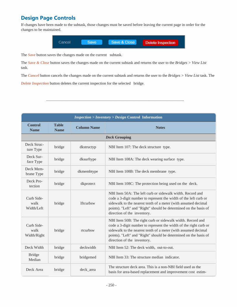
- 250 -
Inspection > Inventory > Design Control Information
Design Page Controls If changes have been made to the subtask, those changes must be saved before leaving the current page in order for the changes to be maintained.
The Save button saves the changes made on the current subtask.
The Save & Close button saves the changes made on the current subtask and returns the user to the Bridges > View List task.
The Cancel button cancels the changes made on the current subtask and returns the user to the Bridges > View List task. The
Delete Inspection button deletes the current inspection for the selected bridge.
_______________________________________________________________________
Control Name
Table Name
Column Name Notes
Deck Grouping
Deck Struc- ture Type
bridge dkstructyp NBI Item 107: The deck structure type.
Deck Sur- face Type
bridge dksurftype NBI Item 108A: The deck wearing surface type.
Deck Mem- brane Type
bridge dkmembtype NBI Item 108B: The deck membrane type.
Deck Pro- tection
bridge dkprotect NBI Item 108C: The protection being used on the deck.
Curb Side-
walk Width/Left
bridge
lftcurbsw
NBI Item 50A: The left curb or sidewalk width. Record and code a 3-digit number to represent the width of the left curb or sidewalk to the nearest tenth of a meter (with assumed decimal points). "Left" and "Right" should be determined on the basis of direction of the inventory.
Curb Side-
walk Width/Right
bridge
rtcurbsw
NBI Item 50B: The right curb or sidewalk width. Record and code a 3-digit number to represent the width of the right curb or sidewalk to the nearest tenth of a meter (with assumed decimal points). "Left" and "Right" should be determined on the basis of direction of the inventory.
Deck Width bridge deckwidth NBI Item 52: The deck width, out-to-out.
Bridge Median
bridge bridgemed NBI Item 33: The structure median indicator.
Deck Area bridge deck_area The structure deck area. This is a non-NBI field used as the basis for area-based replacement and improvement cost estim-

- 251 -
Inspection > Inventory > Design Control Information
Control Name
Table Name
Column Name Notes
ates.
Structure Status Grouping
Bridge Status
bridge bridge_status The current status of the bridge, such as active, inactive, or closed.
Bridge Lifecyle Phase
bridge
bridge_lifecycle_ phase
Indicates the current lifecycle phase of the bridge, such as design or preconstruction.
Spans Grouping
Number of Main Spans
bridge
mainspans
NBI Item 45: Record the number and indicate with a 3-digit code the number of spans in the main or major unit. This item will include all spans of most bridges, the major unit only of a sizable structure, or a unit of material or design different from that of the approach spans.
Main Span Material
bridge materialmain NBI Item 43A: The kind of material and/or design for the main span.
Main Span Design
bridge designmain NBI Item 43B: The type of design and/or construction for the main span.
Number of Approach
Spans
bridge
appspans
NBI Item 46: Record the number and indicate with a 4-digit number the number of spans in the approach spans to the major unit. This item will include all spans of most bridges, the major unit only of a sizable structure, or a unit of material or design different from that of the approach spans.
Approach Span Mater-
ial
bridge
materialappr
NBI Item 44A: The kind of material and/or design for the approach span.
Approach Span Design
bridge designappr NBI Item 44B: The type of design and/or construction for the approach span.
Structure Flared
bridge
strflared
NBI Item 35: Code this item to indicate if the structure is flared, meaning the width of the structure varies. Generally, such vari- ance will result from ramps converging with or diverging from the through lanes on the structure, but there may be other causes. Minor flares at ends of structures should be ignored.
Length Grouping
Maximum Span Length
bridge
maxspan
NBI Item 48: The length of the maximum span shall be recor- ded. It shall be noted whether the measurement is center to cen- ter of bearing points or clear open distance between piers, bents, or abutments. The measurement shall be along the centerline of the bridge. For this item, code a 5-digit number to represent the measurement to the nearest tenth of a meter with an assumed decimal point.
Structure bridge Length
length NBI Item 49: Record and code a 6-digit number to represent the
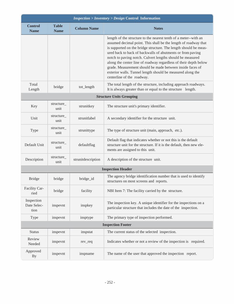
- 252 -
Inspection > Inventory > Design Control Information
Control Name
Table Name
Column Name Notes
length of the structure to the nearest tenth of a meter--with an assumed decimal point. This shall be the length of roadway that is supported on the bridge structure. The length should be meas- ured back to back of backwalls of abutments or from paving notch to paving notch. Culvert lengths should be measured along the center line of roadway regardless of their depth below grade. Measurement should be made between inside faces of exterior walls. Tunnel length should be measured along the centerline of the roadway.
Total Length
bridge tot_length The total length of the structure, including approach roadways. It is always greater than or equal to the structure length.
Structure Units Grouping
Key structure_
unit strunitkey The structure unit's primary identifier.
Unit structure_
unit strunitlabel A secondary identifier for the structure unit.
Type structure_
unit strunittype The type of structure unit (main, approach, etc.).
Default Unit
structure_ unit
defaultflag
Default flag that indicates whether or not this is the default structure unit for the structure. If it is the default, then new ele- ments are assigned to this unit.
Description structure_
unit strunitdescription A description of the structure unit.
Inspection Header
Bridge bridge bridge_id The agency bridge identification number that is used to identify structures on most screens and reports.
Facility Car- ried
bridge facility NBI Item 7: The facility carried by the structure.
Inspection Date Selec-
tion
inspevnt
inspkey
The inspection key. A unique identifier for the inspections on a particular structure that includes the date of the inspection.
Type inspevnt insptype The primary type of inspection performed.
Inspection Footer
Status inspevnt inspstat The current status of the selected inspection.
Review Needed
inspevnt rev_req Indicates whether or not a review of the inspection is required.
Approved By
inspevnt inspname The name of the user that approved the inspection report.

- 253 -
Roads
The Inspection > Inventory > Roads subtask is used to modify the information for roadways on or under the structure including classification data, traffic, clearance, and more.
Adding Records To add an "On" or "Under" structure record, select the Create button.
*Note: The option to add an "On" structure record will only be available if the roadway information that was auto- matically generated when the structure was created was deleted at some point on the Inspection > Inventory > Roads subtask.

- 254 -
In most cases, the roadways being added will be under records. If "One Route Under" is checked, all other options will become read only. This selection indicates that only one under record exists for the bridge.
Checking the box of multiple selections starting with "1st Route Under" allows the user to add more than one under record for the bridge.
When the desired selections have been made, click the Create button to add the under records to the bridge.
Click the Cancel button to cancel the addition of the under records.
Editing Records Once the under records are added, the user can switch between the on record and under records using the Roadway drop- down:
Once a record is selected, the user can fill in the basic information for the record in each of the groupings.
Agency Roadway Fields The Agency Roadway Fields grouping contains blank fields that the agency can define and use as needed. These fields can be defined/changed using the Admin > Navigation and Field Security task. Within the database, these fields are lis- ted in the Roadway table as "userrwkey1," "userrwkey2," etc.
Roads Page Controls If changes have been made to the subtask, those changes must be saved before leaving the current page in order for the changes to be maintained.
The Save button saves the changes made on the current subtask.
The Save & Close button saves the changes made on the current subtask and returns the user to the Bridges > View List task.
The Cancel button cancels the changes made on the current subtask and returns the user to the Bridges > View List task. The
Delete Inspection button deletes the current inspection for the selected bridge.
_______________________________________________________________________
Control Name Table Name
Column Name
Notes
Inspection > Inventory > Roads Control Information
Roadway roadway on_under NBI Item 5A - Used to select the route to view/edit. The route will be either on or under the structure.

- 255 -
Inspection > Inventory > Roads Control Information
Control Name Table Name
Column Name
Notes
Identification Grouping
Road/Route Name
roadway roadway_
name Non-NBI field indicating the name of the roadway.
Position/Prefix roadway on_under NBI Item 5A - Indicates whether the route is on or under the structure.
Kind Hwy (Rt. Prefix)
roadway kind_hwy NBI Item 5B - Identify the route signing prefix for the inventory route.
Desig. Level Service
roadway levl_srvc NBI Item 5C - Identify the designated level of service for the inventory route.
Rte#
roadway
routenum
NBI Item 5D - Code the route number of the inventory route in the next 5 positions. If concurrent routes are of the same hier- archy level, denoted by the route signing prefix, the lowest numbered route shall be coded. Code 00000 for bridges on roads without route numbers.
Suffix roadway dirsuffix NBI Item 5E - Code the directional suffix to the route number of the inventory route when it is part of the route number.
Critical Facility roadway crit_feat NBI Item 6B - Critical Facility Indicator will no longer be coded.
Traffic Grouping
Lanes roadway lanes NBI Item 28A - Indicate the number of lanes on the structure.
Medians roadway num_median Indicates the number of medians on the structure.
Speed roadway road_speed Indicates the speed limit of the roadway.
ADT Class roadway adtclass The traffic volume class of the roadway.
Recent ADT
roadway
adttotal
NBI Item 29 - Code a 6-digit number that shows the average daily traffic (ADT) volume for the inventory route identified in Item 5. The ADT coded should be the most recent ADT counts available. Included in this item are the trucks referred to in Item 109. If the bridge is closed, code the actual ADT from before the closure occurred.
Year roadway adtyear NBI Item 30 - Record the year represented by the ADT in Item 29. Code all four digits of the year.
Truck%
roadway
truckpct
NBI Item 109 - Code a 2-digit percentage that shows the per- centage of Item 29 that is truck traffic. Do not include vans, pickup trucks, and other light delivery trucks in this percentage. If this information is not available, an estimate which represents the average percentage for the category of road carried by the bridge may be used.
Future ADT roadway
adtfuture
NBI Item 114 - Code for all bridges the forecasted average daily traffic (ADT) for the inventory route identified in Item 5. This shall be projected at least 17 years but no more than 22 years from the year of inspection. The intent is to provide a basis for a

- 256 -
Inspection > Inventory > Roads Control Information
Control Name Table Name
Column Name
Notes
20- year forecast. This item may be updated anytime, but must be updated when the forecast falls below the 17-year limit.
NBI Item 115 - Record and code the year represented by the
Future Year roadway adtfutyear future ADT in Item 114. The projected year of future ADT shall be at least 17 years but no more than 22 years from the year of inspection.
Highway Network & Service Classification Grouping
NBI Item 11 - The linear referencing system (LRS) mile- point/kilometer point is used to establish the location of the bridge on the Base Highway Network--see Item 12. The kilo-
Kilometer/Mile Point
National Base Net
LRS Inventory Rte
roadway kmpost
roadway onbasenet
roadway lrsinvrt
meter point coded in this item directly relates to Item 13. This item must be coded for all structures located on or overpassing the Base Highway Network. Code a 7-digit number to represent the LRS kilometer point distance in kilometers to the nearest thousandth with an assumed decimal point.
NBI Item 12 - This item is to be coded for all records in the inventory. The Base Highway Network includes the through lane - mainline - portions of the NHS, rural/urban principal arter- ial system, and rural minor arterial system. Ramps, frontage roads, and other roadways are not included in the Base Network. For the inventory route identified in Item 5, indicate whether the inventory route is on the Base Highway Network or not on that network.
NBI Item 13A - If Item 12 has been coded 1, the information to be recorded for this item is inventory route for the State's linear referencing system (LRS). If Item 12 has been coded 0, this entire item should be left blank.
NBI Item 13B - The subroute number is a number that uniquely identifies portions of an inventory route section where duplicate
Sub# roadway subrtnum
Toll Facility roadway tollfac
kilometer points occur. These subroute numbers, if they exist, are identified in the State's HPMS-LRS records. If there is no sub- route number, code 00 in this segment.
NBI Item 20 - The toll status of the structure is indicated by this item. Interstate toll segments under Secretarial Agreement shall be identified separately.
Functional Class
Traffic Dir- ection
Defense High-
way
roadway funcclass NBI Item 26 - Indicates the functional classification of the road- way.
roadway trafficdir NBI Item 102 - Code the direction of traffic of the inventory route identified in Item 5.
Alternate Classifications Grouping
roadway defhwy NBI Item 100 - This item shall be coded for all records in the inventory. For the purposes of this item, the STRAHNET Con- nectors are considered included in the term STRAHNET.

- 257 -
Inspection > Inventory > Roads Control Information
Control Name Table Name
Nat. Hwy Sys-
Column Name
Notes
NBI Item 104 - This item is to be coded for all records in the
tem roadway nhs_ind
Fed. Lands roadway fedlandhwy
Hwy
inventory. For the inventory route identified in Item 5, indicate whether the inventory route is on the NHS or not.
NBI Item 105 - Structures owned by State and local jurisdictions on roads which lead to and traverse through federal lands some- times require special coded unique identification because they are eligible to receive funding from the Federal Lands Highway Program.
NBI Item 110 - The national network for trucks includes most of the Interstate System and those portions of Federal-Aid highways
Nat. Truck Net- work
roadway trucknet identified in the Code of Federal Regulations--23 CFR 658. The national network for trucks is available for use by commercial motor vehicles of the dimensions and configurations described in these regulations.
School Bus Rte roadway school_bus School bus route indicator. This flag should be set to 1 if the roadway is on a designated school bus route.
Transit Rte roadway transit_rt Transit bus route indicator. This flag should be set to 1 if the roadway is on a designated transit bus route.
Critical travel route indicator. This flag should be set to 1 if the Emergency Rte roadway crit_trav roadway is on a designated critical travel route (e.g., designated
for use during emergency evacuations).
NBI Rte roadway nbi_rw_flag Specifies whether the roadway should be included in NBI file exports.
Clearances Grouping
NBI Item 10 - Code the minimum vertical clearance over the inventory route identified in Item 5, whether the route is on the structure or under the structure. For structures having multiple
Vertical Clear- ance
Horizontal Clearance
roadway vclrinv
roadway hclrinv
openings, clearance for each opening shall be recorded, but only the greatest of the minimum clearances for the two or more open- ings shall be coded regardless of the direction of travel. This would be the practical maximum clearance. When no restriction exists or when the restriction is 30 meters or greater, code 9999.
NBI Item 47 - The total horizontal clearance for the inventory route identified in Item 5 should be measured and recorded. The clearance should be the available clearance measured between the restrictive features and shoulders. When the restriction is 100 meters or greater, code 999. The purpose of this item is to give the largest available clearance for the movement of wide loads. Flush and mountable medians are not considered to be restric- tions.
Widths Grouping
Approach Road roadway aroadwidth NBI Item 32 - Code a 4-digit number to represent the normal width of usable roadway approaching the structure measured to

- 258 -
inspevnt inspkey The inspection key. A unique identifier for the inspections on a particular structure that includes the date of the inspection.
Inspection > Inventory > Roads Control Information
Control Name Table Name
Column Name
Notes
the nearest tenth of a meter. Usable roadway width will include the width of traffic lanes and the widths of shoulders. For struc- tures with medians of any type and double-decked structures, this item should be coded as the sum of the usable roadway widths for the approach roadways. When there is a variation between the approaches at either end of the structure, record and code the most restrictive of the approach conditions.
Roadway roadway roadwidth NBI Item 51 - Represents the most restrictive minimum distance between curbs or rails on the structure roadway.
Detours Grouping
NBI Item 19 - Indicate the actual length to the nearest kilometer
Length roadway bypasslen of the detour length. The detour length should represent the total additional travel for a vehicle which would result from closing of the bridge.
Speed roadway det_speed The speed limit for detouring vehicles.
Accidents Grouping
Count roadway acc_count Average annual accident count for the roadway.
Accident rate in number of accidents per 100m VMT. Currently Rate roadway acc_rate not used, but future safety management system interfaces could
provide this information and lead to improved user cost models.
Roadway Notes Grouping
Roadway Notes roadway notes Roadway notes.
Agency Roadway Fields Grouping
Agency Road- way Field 1
Agency Road- way Field 2
Agency Road- way Field 3
Agency Road- way Field 4
Agency Road- way Field 5
roadway userrwkey1 Agency-defined field 1.
roadway userrwkey2 Agency-defined field 2.
roadway userrwkey3 Agency-defined field 3.
roadway userrwkey4 Agency-defined field 4.
roadway userrwkey5 Agency-defined field 5.
Inspection Header
Bridge bridge bridge_id The agency bridge identification number that is used to identify structures on most screens and reports.
Facility Carried bridge facility NBI Item 7: The facility carried by the structure.
Inspection Date Selection

- 259 -
Inspection > Inventory > Roads Control Information
Control Name Table
Name
inspevnt
Column Name
insptype
Notes
Type
Status inspevnt
Review Needed inspevnt
Approved By inspevnt
The primary type of inspection performed.
Inspection Footer
inspstat The current status of the selected inspection.
rev_req Indicates whether or not a review of the inspection is required.
inspname The name of the user that approved the inspection report.

- 260 -
Agency Bridge Items
The Inspection > Inventory > Agency Bridge Items subtask is an entire page of blank fields that the agency can define and use for any purpose.
Agency Bridge Items Page Controls If changes have been made to the subtask, those changes must be saved before leaving the current page in order for the changes to be maintained.
The Save button saves the changes made on the current subtask.
The Save & Close button saves the changes made on the current subtask and returns the user to the Bridges > View List task.
The Cancel button cancels the changes made on the current subtask and returns the user to the Bridges > View List task.
_______________________________________________________________________
Inspection > Inventory > Agency Items Control Information
Control Name Table Name
Column Name
userkey1 (replace "1" with 2-15)
Notes
Agency Bridge Item (1 through
15) bridge
This field is available for agencies to define and use for any purpose.
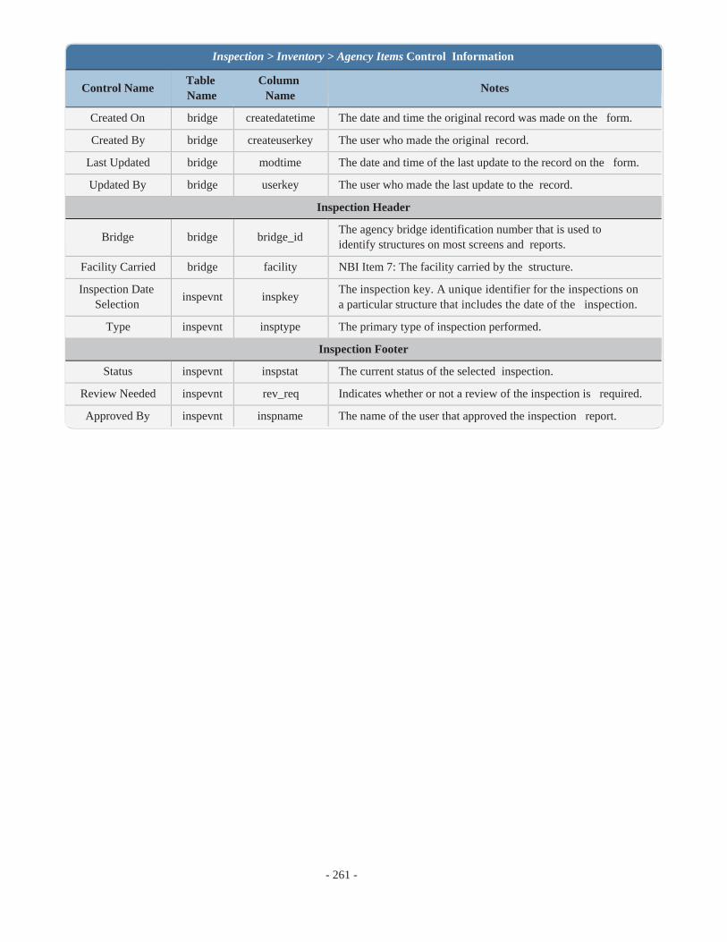
- 261 -
Inspection > Inventory > Agency Items Control Information
Control Name Table Name
Column Name
Notes
Created On bridge createdatetime The date and time the original record was made on the form.
Created By bridge createuserkey The user who made the original record.
Last Updated bridge modtime The date and time of the last update to the record on the form.
Updated By bridge userkey The user who made the last update to the record.
Inspection Header
Bridge bridge bridge_id The agency bridge identification number that is used to identify structures on most screens and reports.
Facility Carried bridge facility NBI Item 7: The facility carried by the structure.
Inspection Date Selection
inspevnt inspkey The inspection key. A unique identifier for the inspections on a particular structure that includes the date of the inspection.
Type inspevnt insptype The primary type of inspection performed.
Inspection Footer
Status inspevnt inspstat The current status of the selected inspection.
Review Needed inspevnt rev_req Indicates whether or not a review of the inspection is required.
Approved By inspevnt inspname The name of the user that approved the inspection report.

- 262 -
The Inspection > Schedule task allows the user to schedule the upcoming inspections for the selected bridge.
*Note: The Inspection > Schedule task has changed from previous versions of BrM. In the past, the Current Date text- boxes displayed the previous inspection date, not the date of the inspection that was just performed/is being performed. In BrM 5.3, the Current Date textboxes display the inspection that was just performed/is being performed, therefore mak- ing it easier to utilize the Current Date and Frequency textboxes to calculate the Next Date inspection.
Summary The Summary grouping contains the information that was entered when the new inspection was created. All of the information in the Summary grouping can be modified except for the read-only checkboxes in the Types of Inspection Performed grouping.
Schedule The Schedule grouping is used to determine the selected bridge's upcoming inspection schedules based on inspection type.
Required Check the Required checkboxes of the inspections that are required for the selected bridge. Routine and element inspec- tions are required NBI inspections and therefore do not have checkboxes.
Current Date The Current Date textbox displays the date of the most recent inspection for the selected bridge based on type of inspec-
tion. The date can be entered manually or the icon can be used to select a date. Inspection types that have not been performed on the selected bridge will default to "01/01/1901."
Schedule

- 263 -
*Note: As stated earlier, BrM 5.3's Current Date textboxes display the inspection that was just performed/is being per- formed.
If the inspection that was just performed/is being performed does not include all of the inspection types, those inspection types' Current Date textboxes will populate with their most recent inspection, if applicable.
Frequency The Frequency textbox is used to determine the number of months between inspections based on type of inspection.
Next Date The Next Date textbox displays the calculated next inspection date based on the Current Date and Frequency inform-
ation. If the calculated date is not the desired date, the date can be entered manually or the icon can be used to select a date.
Inspection Resources The Inspection Resources grouping is used to indicate the next inspector for the bridge, the bridge group, and the crew hours necessary to complete the inspection.
Schedule Page Controls
The Save button saves the changes made to the schedule.
The Save & Close button saves the changes made to the schedule and returns the user to the Bridges > View List task. The
Cancel button cancels the changes made to the schedule and returns the user to the Bridges > View List task.
The Delete Inspection button deletes the current inspection for the selected bridge.
_______________________________________________________________________
Control Name
Table Name
Column Name Notes
Summary Grouping
Date Entered
inspevnt date_entered The date the record was entered.
Inspection Date
inspevnt inspdate The date of the inspection.
Inspector inspevnt inspusrguid The user that performed the inspection.
Primary Type
inspevnt insptype Indicates the primary type of inspection that was performed.
Inspection Group
inspevnt inspectcontrolid An agency-defined group for the bridge inspection. Intended for use in grouping together inspections. Non-NBI field.
Inspection > Schedule Control Information

- 264 -
Inspection > Schedule Control Information
Control Name
Table Name
Column Name Notes
Entered By inspevnt entered_by_gd The user that entered the inspection into the system.
Engineer of Record
inspevnt engineer_of_
record The engineer of record for the inspection.
Types of Inspection Performed Grouping
Routine inspevnt nbinspdone Checked if a routine inspection was performed.
Element inspevnt elinspdone Checked if an element inspection was performed.
Fracture Critical
inspevnt fcinspdone Checked if a fracture critical inspection was performed.
Underwater inspevnt uwinspdone Checked if an underwater inspection was performed.
Other Spe- cial
inspevnt osinspdone Checked if an other special inspection was performed.
Schedule Grouping
Routine Current
Date
inspevnt
lastinsp
NBI Item 90: Record the month and year that the last routine inspection of the structure was performed. This inspection date may be different from those recorded in Item 93.
Routine Frequency
inspevnt brinspfreq NBI Item 91: The routine inspection frequency (in months).
Routine Next Date
inspevnt nextinsp The date of the next scheduled routine inspection. This will auto- matically populate based on the current date and frequency.
Element Current
Date
inspevnt
elinspdate
Record the month and year that the last element inspection of the structure was performed.
Element Frequency
inspevnt elinspfreq The element inspection frequency (in months).
Element Next Date
inspevnt elnextdate The date of the next scheduled element inspection. This will auto- matically populate based on the current date and frequency.
FC Required
inspevnt fcinspreq Specifies whether fracture critical inspections are required for the structure.
FC Current Date
inspevnt
fclastinsp
NBI Item 93A: Record the month and year that the last fracture crit- ical inspection of the structure was performed. This inspection date may be different from that recorded in Item 90.
FC Fre- quency
inspevnt fcinspfreq NBI Item 92AB: The fracture critical inspection frequency (in months).
FC Next Date
inspevnt fcnextdate The date of the next scheduled fracture critical inspection. This will automatically populate based on the current date and frequency.
UW Required
inspevnt uwinspreq Specifies whether underwater inspections are required for the struc- ture.
UW Cur- inspevnt
rent Date uwlastinsp
NBI Item 93B: Record the month and year that the last underwater inspection of the structure was performed. This inspection date may

- 265 -
Inspection > Schedule Control Information
Control Name
Table Name
Column Name Notes
be different from that recorded in Item 90.
UW Fre- quency
inspevnt uwinspfreq NBI Item 92AB: The underwater inspection frequency (in months).
UW Next Date
inspevnt uwnextdate The date of the next scheduled underwater inspection. This will automatically populate based on the current date and frequency.
OS Required
inspevnt osinspreq Specifies whether other special inspections are required for the struc- ture.
OS Current Date
inspevnt
oslastinsp
NBI Item 93C: Record the month and year that the last other spe- cial inspection of the structure was performed. This inspection date may be different from that recorded in Item 90.
OS Fre- quency
inspevnt osinspfreq NBI Item 92AB: The other special inspection frequency (in months).
OS Next Date
inspevnt osnextdate The date of the next scheduled other special inspection. This will automatically populate based on the current date and frequency.
Inspection Resources Grouping
Next
Inspector
bridge
nextinspid
Non-NBI field maintained by the system by default. BrM auto- matically fills in this field by copying the user key of the person doing the current inspection. An inspector may change this assign- ment if desired.
Bridge Group
bridge bridgegroup An agency-defined group for the bridge. Intended for use in group- ing together bridges for inspection purposes. Non-NBI field.
Crew Hours
bridge crewhrs The number of crew hours required for a regular inspection for the structure.
Flagger Hours
bridge flaggerhrs The number of flagger hours required for a regular inspection for the structure.
Helper Hours
bridge helperhrs The number of helper hours required for a regular inspection for the structure.
Snooper Hours
bridge snooperhrs The number of snooper hours required for a regular inspection for the structure.
Special Crew Hours
bridge
spcrewhrs
The number of special crew hours required for a regular inspection for the structure.
Special Equipment
Hours
bridge
spequiphrs
The number of special equipment hours required for a regular inspection for the structure.
Schedule Notes Grouping
Inspection Schedule
Notes
inspevnt
schedule_notes
Notes relating to the current inspection's scheduling.

- 266 -
Inspection > Schedule Control Information
Control Name
Table Name
Column Name Notes
Inspection Header
Bridge bridge bridge_id The agency bridge identification number that is used to identify structures on most screens and reports.
Facility Carried
bridge facility NBI Item 7: The facility carried by the structure.
Inspection Date Selec-
tion
inspevnt
inspkey
The inspection key. A unique identifier for the inspections on a par- ticular structure that includes the date of the inspection.
Type inspevnt insptype The primary type of inspection performed.
Inspection Footer
Status inspevnt inspstat The current status of the selected inspection.
Review Needed
inspevnt rev_req Indicates whether or not a review of the inspection is required.
Approved By
inspevnt inspname The name of the user that approved the inspection report.

- 284 -
The Inspection > Element Condition Ratings task displays a read-only history of both the NBI ratings and element con- ditions for the selected bridge. Users can utilize this page to view how a bridge's NBI ratings or element conditions have changed over time.
Element Condition Ratings


- The Gateway section of the manual addresses each of the tasks in BrM's Gateway tab. The Gateway tab provides the tools to import and export data between BrM and other systems.
Gateway

- 307 -
The Gateway > Export task allows the user to export the data determined on the Admin > General Config > Export Options task to various export files.
Export Controls Selected Bridges The Selected Bridges grid displays all of the bridges currently selected on the Bridge List. It is only visible when at least one bridge is selected.
Export What? The Export What? dropdown is used to pick the type of export file that will be created. The options include: XML, non-compressed XML, PDI, custom PDI, a metric NBI file, and an NBE file.
The inputs for the NBI and NBE files are set, therefore the Include: dropdown is read only for those exports because no selection needs to be made from it.
If the NBE file is selected, a new option will appear in the Export Which Bridges? grouping.
Export

- 308 -
Include: The Include: dropdown is used to select one of the export options determined on the Admin > General Config > Export Options task. This is the information that will be exported from the selected bridges.
Validate Data When "NBE XML" is selected from the Export What? dropdown, the Validate Data button will appear so the user can validate the selected bridges.
*Note: The Validate Data button will not appear for any selections other than "NBE XML."
Export Which Bridges? The Export Which Bridges? radio buttons determine whether the exported file will include only the selected bridges or all of the bridges in the database.
If no bridges are currently selected on the Bridge List, the Selected Bridges radio button will be read only.
*Note: An additional radio button - "Only Bridges on the NHS" - appears when "NBE XML" is selected from the Export What? dropdown.
Export Once the desired selections have been made, click the Export button to create the exported file.

- 309 -
The Gateway > Import task allows the user to import various file types to the database.
Import Controls Import What? The Import what? dropdown allows the user to choose the type of file that will be imported. The options include PDI, NBI, and XML files.
Input File: The Input File: field displays the file that has been selected. To select a file, click the Select button and locate the desired file.
Options The Options grouping contains the options available for the import of an NBI File. It will be read only for PDI and XML files.
The Update Only checkbox will update the database based on the imported NBI file.
The Create New Inspections checkbox will create new inspections based on the imported NBI file.
The Import UOM radio buttons allow the user to choose which units to use for the import.
Import Once the desired selections have been made, click the Import button to import the selected file.
Import

- 310 -
The Gateway > Check Out task allows the user to check out bridges from the system. Checking out a bridge can be thought of as locking the bridge. It does not mean that updates cannot be made to the bridge once it's checked out, but rather that any updates made will have to be accepted once the bridge is checked back in.
Check Out Controls Selected Bridges The Selected Bridges grouping displays all of the bridges currently selected on the Bridge List. It is only visible when at least one bridge is selected.
Check Out What? The Check Out What? dropdown is used to determine the file type that will be created with the check out.
Include: The Include: dropdown is used to determine what information about the selected bridges will be checked out for the PDI file. This option is read only for custom PDI files.
Check Out Which Bridges? The Check Out Which Bridges? radio buttons determine which bridges will be checked out. If no bridges are currently selected on the Bridge List, the Selected Bridges radio button will be read only.
Check Out Once the desired selections have been made, click the Check Out button to check out the selected bridges.
*Note: The following will occur if WARNONEDITFORCHECKEDOUTBRIDGE is set to "Y" on the Admin > General Config > Options task:
When entering the Inspection module with a checked out bridge selected, a popup message will notify the user of the
bridge's status and a symbol will appear next to the bridge's ID in the Inspection module header.
Check Out

- 311 -
The Gateway > Check In task allows the user to check bridges back into the system. If a bridge has been modified while checked out, checking the bridge back in will take the user to the Gateway > Override task to determine if the changes to the bridge should be accepted.
Check-In Controls Check-In Data The Check In What? dropdown determines the type of file that will be checked in.
The Input File: Choose File button is used to select the check in file. This is the same file that was obtained when the bridge was checked out. If the file has been lost, there will be no way to override the changes that have occurred to the bridge since it was checked out.
Check In and Re-Check In The Check In button is used to perform the initial check in of a checked out bridge.
The Re-Check In button is used to check in a bridge after the changes have been accepted on the Gateway > Override task, as indicated by the note under the button that reads: "Only check-in accepted conflicts."
Check In

- 312 -
The Gateway > Override task allows the user to decide whether or not to accept the changes that have been made to a bridge since it's been checked out.
Override Controls PDI Selection Use the PDI dropdown to select the PDI to view. The name of the PDI will match that of the PDI that was checked in.
Display Use the Display radio buttons to show either all of the rows or only the rows with changes that have been unaccepted. The table will indicate if there is nothing to display for the selected radio button.
Delete All Rows The Delete All Rows for this PDI File button will delete all of the displayed rows in the list for the selected radio but- ton.
l If the Delete button is clicked when the All Rows radio button is selected, all of the rows within the All Rows list will be transferred to the Unaccepted Rows list.
l If the Delete button is clicked when the Unaccepted Rows radio button is selected, all of the rows within the Unaccepted Rows list will be deleted.
If there are no more rows listed in both the All Rows list and the Unaccepted Rows list, the PDI will automatically be removed from the Gateway > Override task.
Override

- 315 -
Accept, Accept All, and Close The Accept button accepts all of the checked rows for the selected PDI. The changes that occurred to the bridge while checked out will be made permanent when the bridge is re-checked in to the system on the Gateway > Check In task.
The Accept All button accepts all of the displayed rows, regardless of check status, for the selected PDI. The changes that occurred to the bridge while checked out will be made permanent when the bridge is re-checked in to the system on the Gateway > Check In task.
Selecting the Cancel button cancels the currently selected PDI's changes (prior to being accepted) and returns the user to the All Rows list of the first PDI listed in the PDI dropdown.

- 314 -