Brittle Cracking of a Cylindrical Spiral Gear of Axle Gearbox
8
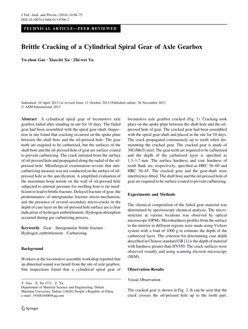
TECHNICAL ARTICLE—PEER-REVIEWED Brittle Cracking of a Cylindrical Spiral Gear of Axle Gearbox Yu-zhou Gao • Xiao-lei Xu • Zhi-wei Yu Submitted: 10 April 2013 / in revised form: 11 October 2013 / Published online: 26 November 2013 Ó ASM International 2013 Abstract A cylindrical spiral gear of locomotive axle gearbox failed after standing in site for 10 days. The failed gear had been assembled with the spiral gear-shaft. Inspec- tion in site found that cracking occurred on the spoke plate between the shaft bore and the oil-pressed hole. The gear teeth are required to be carburized, but the surfaces of the shaft bore and the oil-pressed hole of gear are surface-coated to prevent carburizing. The crack initiated from the surface of oil-pressed hole and propagated along the radial of the oil- pressed hole. Metallurgical examination reveals that anti- carburizing measure was not conducted on the surface of oil- pressed hole as the specification. A simplified evaluation of the maximum hoop tensile on the wall of oil-pressed hole subjected to internal pressure for swelling bore is far insuf- ficient to lead to brittle fracture. Delayed fracture of gear, the predominance of intergranular fracture micro-mechanism, and the presence of several secondary micro-cracks in the depth of case layer on the oil-pressed hole surface are a clear indication of hydrogen embrittlement. Hydrogen absorption occurred during gas carburizing process. Keywords Gear Intergranular brittle fracture Hydrogen embrittlement Carburizing Background Workers at the locomotive assemble workshop reported that an abnormal sound was heard from the site of axle gearbox. Site inspections found that a cylindrical spiral gear of locomotive axle gearbox cracked (Fig. 1). Cracking took place on the spoke plate between the shaft hole and the oil- pressed hole of gear. The cracked gear had been assembled with the spiral gear-shaft and placed in the site for 10 days. The crack propagated continuously up to tooth when dis- mounting the cracked gear. The cracked gear is made of 30CrMnTi steel. The gear teeth are required to be carburized and the depth of the carburized layer is specified as 1.3–1.7 mm. The surface hardness and core hardness of tooth flank are, respectively, specified as HRC 56–60 and HRC 30–45. The cracked gear and the gear-shaft were interference-fitted. The shaft bore and the oil-pressed hole of gear are required to be surface-coated to prevent carburizing. Experiments and Methods The chemical composition of the failed gear material was determined by spectroscopy chemical analysis. The micro- structure at various locations was observed by optical microscope (OPM). Microhardness profiles from the surface to the interior in different regions were made using Vickers system with a load of 1000 g to estimate the depth of the carburized layer. The criterion for determining case depth described in Chinese standard GB [1] is the depth of material with hardness greater than HV550. The crack surfaces were observed visually and using scanning electron microscopy (SEM). Observation Results Visual Observation The cracked gear is shown in Fig. 2. It can be seen that the crack crosses the oil-pressed hole up to the tooth part. Y. Gao X. Xu (&) Z. Yu Department of Material Science and Engineering, Dalian Maritime University, Dalian 116026, People’s Republic of China e-mail: [email protected] 123 J Fail. Anal. and Preven. (2014) 14:68–75 DOI 10.1007/s11668-013-9766-2
Transcript of Brittle Cracking of a Cylindrical Spiral Gear of Axle Gearbox
TECHNICAL ARTICLE—PEER-REVIEWED
Brittle Cracking of a Cylindrical Spiral Gear of Axle Gearbox
Yu-zhou Gao • Xiao-lei Xu • Zhi-wei Yu
Submitted: 10 April 2013 / in revised form: 11 October 2013 / Published online: 26 November 2013
� ASM International 2013
Abstract A cylindrical spiral gear of locomotive axle
gearbox failed after standing in site for 10 days. The failed
gear had been assembled with the spiral gear-shaft. Inspec-
tion in site found that cracking occurred on the spoke plate
between the shaft bore and the oil-pressed hole. The gear
teeth are required to be carburized, but the surfaces of the
shaft bore and the oil-pressed hole of gear are surface-coated
to prevent carburizing. The crack initiated from the surface
of oil-pressed hole and propagated along the radial of the oil-
pressed hole. Metallurgical examination reveals that anti-
carburizing measure was not conducted on the surface of oil-
pressed hole as the specification. A simplified evaluation of
the maximum hoop tensile on the wall of oil-pressed hole
subjected to internal pressure for swelling bore is far insuf-
ficient to lead to brittle fracture. Delayed fracture of gear, the
predominance of intergranular fracture micro-mechanism,
and the presence of several secondary micro-cracks in the
depth of case layer on the oil-pressed hole surface are a clear
indication of hydrogen embrittlement. Hydrogen absorption
occurred during gas carburizing process.
Keywords Gear � Intergranular brittle fracture �Hydrogen embrittlement � Carburizing
Background
Workers at the locomotive assemble workshop reported that
an abnormal sound was heard from the site of axle gearbox.
Site inspections found that a cylindrical spiral gear of
locomotive axle gearbox cracked (Fig. 1). Cracking took
place on the spoke plate between the shaft hole and the oil-
pressed hole of gear. The cracked gear had been assembled
with the spiral gear-shaft and placed in the site for 10 days.
The crack propagated continuously up to tooth when dis-
mounting the cracked gear. The cracked gear is made of
30CrMnTi steel. The gear teeth are required to be carburized
and the depth of the carburized layer is specified as
1.3–1.7 mm. The surface hardness and core hardness of
tooth flank are, respectively, specified as HRC 56–60 and
HRC 30–45. The cracked gear and the gear-shaft were
interference-fitted. The shaft bore and the oil-pressed hole of
gear are required to be surface-coated to prevent carburizing.
Experiments and Methods
The chemical composition of the failed gear material was
determined by spectroscopy chemical analysis. The micro-
structure at various locations was observed by optical
microscope (OPM). Microhardness profiles from the surface
to the interior in different regions were made using Vickers
system with a load of 1000 g to estimate the depth of the
carburized layer. The criterion for determining case depth
described in Chinese standard GB [1] is the depth of material
with hardness greater than HV550. The crack surfaces were
observed visually and using scanning electron microscopy
(SEM).
Observation Results
Visual Observation
The cracked gear is shown in Fig. 2. It can be seen that the
crack crosses the oil-pressed hole up to the tooth part.
Y. Gao � X. Xu (&) � Z. Yu
Department of Material Science and Engineering, Dalian
Maritime University, Dalian 116026, People’s Republic of China
e-mail: [email protected]
123
J Fail. Anal. and Preven. (2014) 14:68–75
DOI 10.1007/s11668-013-9766-2

Visual observation shows the appearance of crack on the
surface of shaft bore (Fig. 3). The crack is throughout the
whole internal surface of the shaft bore. Close-up view
shows that the crack is generally straight but with a small
deflection at the tooth part (Fig. 4). The crack is straight at
the upper portion of oil storage slot, but the zigzag-shaped
crack is present at the lower portion (Figs. 3, 4d). No
abnormal contact marks were found on the surface of shaft
bore.
Fracture was prepared by carefully pulling the crack
surfaces apart to facilitate examination and identifica-
tion of the fracture mechanism. The fracture surface
shows typical chevron marks originating from the ini-
tiating sites (Fig. 5), which shows macroscopically
embrittlement [2]. The fracture surface reveals three
Fig. 2 Cracked gear
Fig. 3 Crack morphology on the surface of shaft hole
Fig. 4 Close-up observation on crack morphology: (a) upper end of
gear, (b) lower end of gear, (c) tooth flank, (d) surface of shaft hole
Fig. 1 Cracked gear and gear-shaft assembled (offered by
manufacturer)
J Fail. Anal. and Preven. (2014) 14:68–75 69
123

distinguishable zones from the crack propagation
marks, which are marked as I, II, and III. From macro
observation, it can be determined that the crack initi-
ated from the surface of the oil-pressed hole and
propagated along the radial of the oil-pressed hole to
form zone I and zone II, then propagating along the
radial of the gear to form zone III. It is noted that the
fracture surface at two sides of the oil-pressed hole
exhibits a silvery gray layer of 1–2 mm (Fig. 5b).
SEM Observation
The fracture surface in the vicinity of the oil-pressed hole and
the shaft bore was emphatically observed by SEM. At two
sides of the thick oil-pressed hole (Fig. 6) and the left side of
thin oil-pressed hole (Fig. 7a, b), particularly in a depth of
around 1 mm, the nature of the fracture is almost totally
intergranular, but cleavage or quasi-cleavage morphology is
revealed at the right side of thin oil-pressed hole (Fig. 7c, d).
The secondary cracks and ductile tearing [3] were found on
intergranular fracture surface (Figs. 6b, d, 7b). The fracture
surface both in the tightened and the un-tightened thread
regions of thick oil-pressed hole reveals similar fracto-
graphic features. It is suggested that the characteristic of
intergranular fracture in the thread region is not related to the
tightening operation. The fracture surface close to the shaft
bore (region F1 in Fig. 5b) and away from the oil-pressed
hole (regions F2, F3, and F4 in Fig. 5b) shows quasi-cleav-
age coexisting a small amount of shallow dimples or
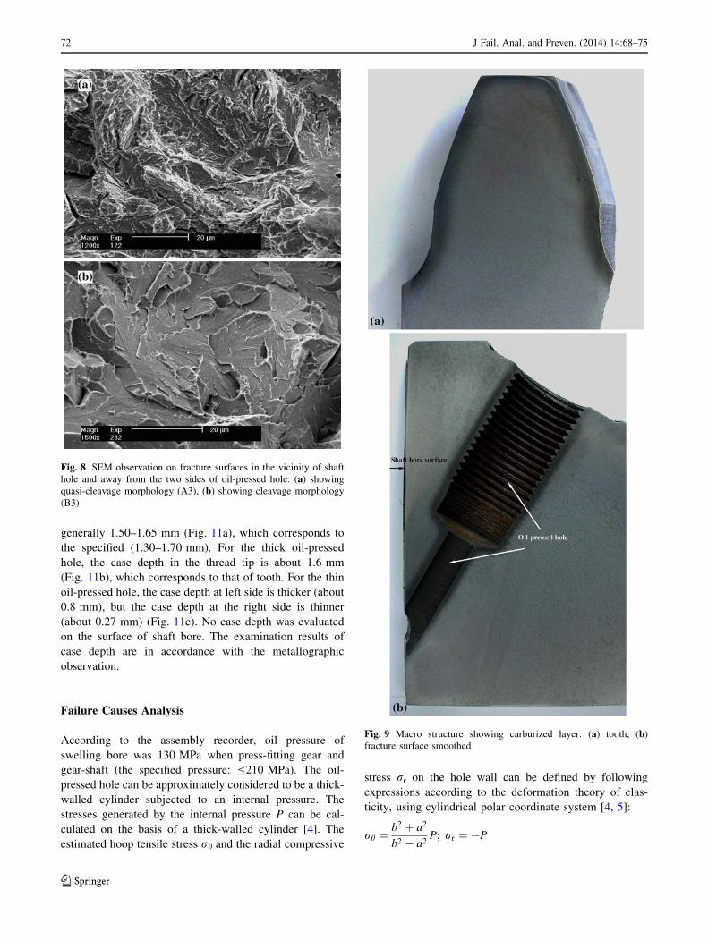
cleavage morphology (Fig. 8).
Microstructure Examination
The cross-sectional metallographic specimen through gear
tooth and the metallographic specimen of the fracture
surface smoothed were prepared. From the macro mor-
phology of the metallographic specimens, it can be seen
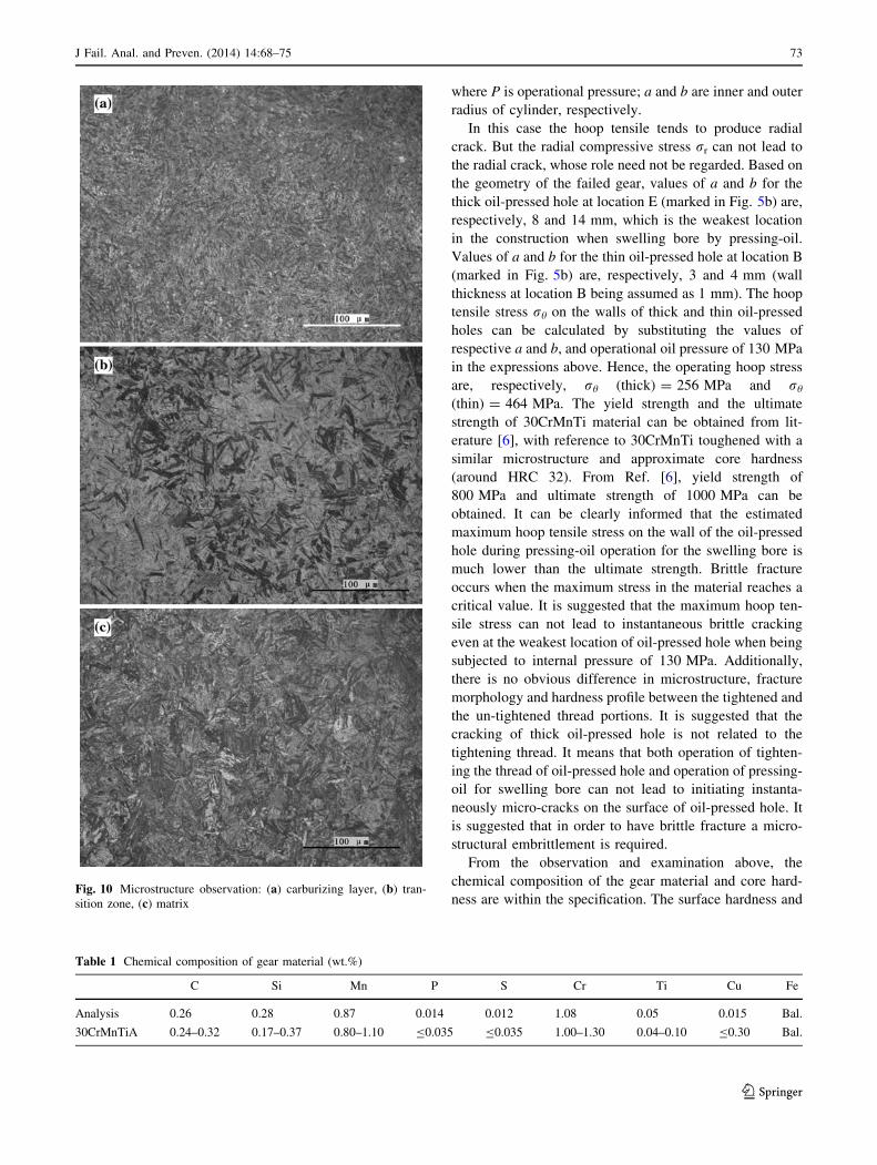
that the outline of tooth had been case hardened to a depth
of approximately 1.5 mm (Fig. 9a). The macro-case layer
was revealed on the surface of the oil-pressed hole
(Fig. 9b), suggesting that operating of anti-carburizing was
not conducted on the surface of oil-pressed hole. The case
depth on the surface of thin oil-pressed hole, especially at
the right side, is thinner than that of thick oil-pressed hole.
Absence of case layer on the surface of shaft bore suggests
that the operating of anti-carburizing was conducted on the
surface of shaft bore.
The microstructure of the carburized layer is mainly
composed of the fine needle-like martensite and the
retained austenite without intergranular network-like car-
bides and oxides (Fig. 10a). The microstructure of the
transition region between the case and the core is com-
posed of the martensite and the lower-bainite (Fig. 10b).
The core is composed of the lath-martensite and upper-
bainite (Fig. 10c).
The examination on the chemical composition of the
failed gear materials indicates that the failed gear was
fabricated from 30CrMnTi steel (Table 1).
Hardness Examination
The surface and core hardness values of tooth (average
value of three readings) are, respectively, HRC 60.0 and
HRC 32.8. These hardness values are corresponding to the
specified.
The microhardness profiles in pitch, tip, and groove
regions of tooth, and representative regions of the oil-
pressed hole from the surface to the interior were measured
(Fig. 11). It can be seen that the case depth of tooth part is
Fig. 5 Macro-fracture surface: (a) general view, (b) close-up view on
the vicinity of oil-pressed hole
70 J Fail. Anal. and Preven. (2014) 14:68–75
123

Fig. 6 SEM observation on fracture surface in the vicinity of thick oil hole: (a) low magnified view (left side), (b) boxed zone in (a) showing
intergranular fracture, (c) low magnified view (right side), (d) boxed zone in (c) showing intergranular fracture
Fig. 7 SEM observation on fracture surface in the vicinity of thin oil hole: (a) low magnified view (left side), (b) boxed zone in (a) showing
intergranular fracture, (c) low magnified view (right side), (d) boxed zone in (c) showing cleavage morphology
J Fail. Anal. and Preven. (2014) 14:68–75 71
123
generally 1.50–1.65 mm (Fig. 11a), which corresponds to
the specified (1.30–1.70 mm). For the thick oil-pressed
hole, the case depth in the thread tip is about 1.6 mm
(Fig. 11b), which corresponds to that of tooth. For the thin
oil-pressed hole, the case depth at left side is thicker (about
0.8 mm), but the case depth at the right side is thinner
(about 0.27 mm) (Fig. 11c). No case depth was evaluated
on the surface of shaft bore. The examination results of
case depth are in accordance with the metallographic
observation.
Failure Causes Analysis
According to the assembly recorder, oil pressure of
swelling bore was 130 MPa when press-fitting gear and
gear-shaft (the specified pressure: B210 MPa). The oil-
pressed hole can be approximately considered to be a thick-
walled cylinder subjected to an internal pressure. The
stresses generated by the internal pressure P can be cal-
culated on the basis of a thick-walled cylinder [4]. The
estimated hoop tensile stress rh and the radial compressive
stress rr on the hole wall can be defined by following
expressions according to the deformation theory of elas-
ticity, using cylindrical polar coordinate system [4, 5]:
rh ¼b2 þ a2
b2 � a2P; rr ¼ �P
Fig. 8 SEM observation on fracture surfaces in the vicinity of shaft
hole and away from the two sides of oil-pressed hole: (a) showing
quasi-cleavage morphology (A3), (b) showing cleavage morphology
(B3)
Fig. 9 Macro structure showing carburized layer: (a) tooth, (b)
fracture surface smoothed
72 J Fail. Anal. and Preven. (2014) 14:68–75
123
where P is operational pressure; a and b are inner and outer
radius of cylinder, respectively.
In this case the hoop tensile tends to produce radial
crack. But the radial compressive stress rr can not lead to
the radial crack, whose role need not be regarded. Based on
the geometry of the failed gear, values of a and b for the
thick oil-pressed hole at location E (marked in Fig. 5b) are,
respectively, 8 and 14 mm, which is the weakest location
in the construction when swelling bore by pressing-oil.
Values of a and b for the thin oil-pressed hole at location B
(marked in Fig. 5b) are, respectively, 3 and 4 mm (wall
thickness at location B being assumed as 1 mm). The hoop
tensile stress rh on the walls of thick and thin oil-pressed
holes can be calculated by substituting the values of
respective a and b, and operational oil pressure of 130 MPa
in the expressions above. Hence, the operating hoop stress
are, respectively, rh (thick) = 256 MPa and rh
(thin) = 464 MPa. The yield strength and the ultimate
strength of 30CrMnTi material can be obtained from lit-
erature [6], with reference to 30CrMnTi toughened with a
similar microstructure and approximate core hardness
(around HRC 32). From Ref. [6], yield strength of
800 MPa and ultimate strength of 1000 MPa can be
obtained. It can be clearly informed that the estimated
maximum hoop tensile stress on the wall of the oil-pressed
hole during pressing-oil operation for the swelling bore is
much lower than the ultimate strength. Brittle fracture
occurs when the maximum stress in the material reaches a
critical value. It is suggested that the maximum hoop ten-
sile stress can not lead to instantaneous brittle cracking
even at the weakest location of oil-pressed hole when being
subjected to internal pressure of 130 MPa. Additionally,
there is no obvious difference in microstructure, fracture
morphology and hardness profile between the tightened and
the un-tightened thread portions. It is suggested that the
cracking of thick oil-pressed hole is not related to the
tightening thread. It means that both operation of tighten-
ing the thread of oil-pressed hole and operation of pressing-
oil for swelling bore can not lead to initiating instanta-
neously micro-cracks on the surface of oil-pressed hole. It
is suggested that in order to have brittle fracture a micro-
structural embrittlement is required.
From the observation and examination above, the
chemical composition of the gear material and core hard-
ness are within the specification. The surface hardness andFig. 10 Microstructure observation: (a) carburizing layer, (b) tran-
sition zone, (c) matrix
Table 1 Chemical composition of gear material (wt.%)
C Si Mn P S Cr Ti Cu Fe
Analysis 0.26 0.28 0.87 0.014 0.012 1.08 0.05 0.015 Bal.
30CrMnTiA 0.24–0.32 0.17–0.37 0.80–1.10 B0.035 B0.035 1.00–1.30 0.04–0.10 B0.30 Bal.
J Fail. Anal. and Preven. (2014) 14:68–75 73
123

the case depth of tooth correspond to the specified. How-
ever, the anti-carburizing measure was not performed on
the surface of oil-pressed hole. Unfortunately, the crack
just initiated from the surface of oil-pressed hole. It is
deduced that the failure of the gear is closely related to the
presence of carburized layer on the surface of oil-pressed
hole. From observation on the fracture exposed, the inter-
granular fracture morphology only appears in the case-
hardened layer of oil-pressed hole, while, the core reveals
cleavage morphology. And the thicker case depth exhibits
more obvious intergranular topography and higher inter-
granular fracture depth on the fracture surface (such as at
the two sides of thick oil-pressed hole and the left side of
thin oil-pressed hole). At the right side of thin oil-pressed
hole with a thin case-hardened layer, the characteristic of
intergranular fracture was not found. It implies that the
intergranular fracture may be representative of the char-
acteristic of the case-hardened layer other than the gear
material. It can be excluded that the defects of original
material and unsuitable integrated heat treatment (such as
tempered brittle) led to the intergranular brittle fracture.
Appearance of the intergranular fracture has relation to the
carburizing process. Intergranular brittle fracture may
occur if the prior austenite grain boundaries are embrittled.
In general, such an embrittlement is associated with high
phosphorus and carbon concentration in the base steel or
with hydrogen absorption from the carburizing atmosphere
[7, 8]. Another microstructural feature to consider when
dealing with the brittle fracture of carburized parts is the
possible formation of surface intergranular oxidation [9].
However, in present case, no intergranular internal oxida-
tion occurred on the case-hardened layer. In addition, grain
boundary carbides were not found in the carburized layer.
Phosphorous may segregate at the austenite grain bound-
aries during the carburizing process and reduce grain
boundary cohesion [10]. Chemical analysis of the steel,
however, reveals a low phosphorous content (in agreement
with the standard specification) and serious phosphorus
segregation on the intergranular fracture surface was not
probed by EDS. In order to determine if impurity (phos-
phorus) segregation is associated with the grain boundary
fracture noted on the carburized layer, an Auger analysis
should be performed [11]. The delayed brittle fracture
behavior in present case suggests the intergranular
embrittlement fracture should be more closely related to
the hydrogen embrittlement.
The carburizing media mainly contains acetone
(CH3COCH3) as carburizing agent and methanol (CH3OH)
as diluents. In gas carburizing process, the following
reaction would occur:
CH3COCH3 ! COþ 2Cþ 3H2;
CH3OH! COþ 2H2
Therefore, the carburized parts are in the atmosphere of
hydrogen and high temperature. Hydrogen absorption may
occur during gas carburizing. The authors studied the
influence of hydrogen on the critical fracture stress of
steels and they found that the brittle fracture stress is reduced
Fig. 11 Microhardness profile of various regions: (a) tooth, (b) thick
oil-pressed hole, (c) thin oil-pressed hole
74 J Fail. Anal. and Preven. (2014) 14:68–75
123

by 200–300 MPa when 1 ppm of hydrogen is absorbed in the
steel [8, 12]. Moreover, in view of the construction of oil-
pressed hole, it is difficult for the hydrogen atoms segregated
to tensile stress zone of subsurface to escape in the process of
heating after carburizing (tempering process). Under the
action of interference-fitting stress, the absorbed hydrogen
atoms would enrich into the grain boundary of the surface of
oil-pressed hole. As the hydrogen content at the boundary
increases, the interfacial strength decreases, leading to
initiation of intergranular cracks. A further support to the
hypothesis of the hydrogen embrittlement is given by the
presence of several secondary cracks on the fracture surface.
Conclusions
(1) The chemical composition and the core hardness of
the failed gear are within the range of the specifi-
cation. The surface hardness and the case depth of
gear tooth correspond to the specification.
(2) Anti-carburizing measure was not performed on the
surface of oil-pressed hole as specification, leading
to the presence of a case layer of 0.3–1.6 mm.
(3) The observed micro-mechanism on the fracture
surface at the carburized layer of oil-pressed hole
was predominantly intergranular.
(4) A simplified evaluation of the maximum hoop
tensile on the wall of oil-pressed hole subjected to
internal pressure for swelling bore is far insufficient
to lead to brittle fracture. The delayed fracture of the
gear and the predominance of intergranular fracture
micro-mechanism at the carburized layer are a most
likely indication of the hydrogen embrittlement.
Hydrogen absorption may occur during gas carbu-
rizing process.
Recommendations
Anti-carburizing measurement on the oil-pressed hole
should be strictly performed to avoid producing brittle case
layer on the surface of oil-pressed hole and leading to
brittle cracking of oil-pressed hole under the action of
interference-fitting stress when press-fitting gear.
References
1. Determination of Carburized Depth and Metallurgic Examination of
Carburizing Structure (GB9450, China Standard, 1994) (in Chinese)
2. Metal Hand Book. Fractography and Atlas of Fractographs, 8th
edn., vol. 9 (American Society for Metals, Metal Park, OH, 1974)
3. A.K. Jha, K. Sreekumar, Hydrogen-induced cracking (HIC) of
hardened and tempered steel fastener used in space application. J.
Fail. Anal. Prev. 9, 420–428 (2009)
4. M.J. Hyder, M. Asif, Optimization of location and size of
opening in pressure vessel cylinder using ANSYS. Eng. Fail.
Anal. 15, 1–19 (2008)
5. J. Purbolaksono, Y.W. Hong, S.S.M. Nor, H. Othman, B. Ahmad,
Evaluation on reheater tube failure. Eng. Fail. Anal. 16, 533–537 (2009)
6. Z.-Z. Hu, Steel and Heat Treatment Curves Handbook (National
Defense Industry Press, Beijing, 1986) (in Chinese)
7. G. Krauss, Steel: Heat Treatment and Processing Principle (ASM
International, Materials Park, 2000)
8. G. Straffelini, L. Versari, Brittle intergranular fracture of a
thread: the role of a carburizing treatment. Eng. Fail. Anal. 16,
1448–1453 (2009)
9. O. Asi, A.C. Can, J. Pineault, M. Belassel, The relationship
between case depth of gas carburized SAM 8620 steel. Surf.
Coat. Technol. 201, 5979–5987 (2007)
10. G. Krauss, Steel: Heat Treatment and Processing Principles
(ASM International, Materials Park, 2000)
11. G. Krauss, The microstructure and fracture of a carburized steel.
Metall. Trans. 9A, 1527–1535 (1978)
12. H. Streng, C. Razim, J. Grosh, Influence of hydrogen and tem-
pering on the toughness of case-hardened structures. In
Carburizing: Processing and Performance (Lakewood, 1989)
J Fail. Anal. and Preven. (2014) 14:68–75 75
123