Bristol Water AMP5 UV Schemes
5
Bristol Water AMP5 UV Schemes Purton WTW, the first of 4 ultraviolet light installations for the treatment of Cryptosporidium for Bristol Water by Trevor Farrow BSc (Hons) CEng MIMechE T he use of UV to render Cryptosporidium non-viable is covered by new guidance issued by the Drinking Water Inspectorate in February 2010. Bristol Water’s UV schemes are some of the first in the UK to be designed specifically to meet the requirements of the new guidance criteria. The article presented here is subsequent to the one written by Bill Irvine of Atkins and presented in UK Water Projects 2011, which set out the design basis and selection criteria for the four new build UV installations on behalf of Bristol Water to provide Cryptosporidium and primary disinfection control. This article moves on to the construction stage providing details of the individual design and build projects. Project overview Following the successful award in March 2011 of a competitively bid Framework Agreement with Bristol Water for the AMP 5 period, Enpure was awarded the first call off contract under the agreement for the design, build and commissioning of the four new UV Installations. The first of the builds at Purton Treatment Works had the highest priority with a taking-over and DWI compliance date on 31 December 2011 ie; a 42 week total project time from contract award. Later compliance dates were set for Littleton (December 2012), Cheddar (October 2013) and Stowey (October 2013). To achieve the required deadline, the design team had to hit the ground running and from the outline tender design produced by Atkins, develop the detail design while in parallel continuing with project procurement and construction phases. The civil works for the four projects was competitively tendered with Enpure making an award to Dean and Dyball Civil Engineering under the terms of a domestic consortium arrangement. Purton WTW The UV installation at Purton Treatment Works is located between the outlet from the existing GAC contactors and the inlet to the existing 2 (No.) clear water tanks with final chlorination, pH correction (sodium hydroxide) and phosphoric acid dosing at points along the interconnecting pipework. The principal process units comprise 2 (No.) inlet tanks, a single distribution chamber that supplies 3 (No.) 800Nb UV reactor streams (configured duty/assist/assist) and 3 (No.) receiving reactor catchment chambers (RCCs) within each of which is installed an axial flow variable speed lineshaft pump (each rated at 82.5Mld) that pumps water into a common system of 1200Nb pipework to connect with the existing 2 (No.) clear water tanks. Installed within each of the reactor streams is a system of actuated gate and butterfly valves together with electromagnetic flowmeter and these provide the necessary isolation and modulating flow www.WaterProjectsOnline.com Water Treatment & Supply UK Water Projects 2012 Page 291 UV Plant Area (reactor streams) - Courtesy of Enpure Ltd
Transcript of Bristol Water AMP5 UV Schemes
Bristol Water AMP5 UV SchemesPurton WTW, the first of 4 ultraviolet light installationsfor the treatment of Cryptosporidium for Bristol Water
by Trevor Farrow BSc (Hons) CEng MIMechE
The use of UV to render Cryptosporidium non-viable is covered by new guidance issued by the Drinking Water Inspectorate in February 2010. Bristol Water’s UV schemes are some of the first in the UK to be designed specifically to meet the requirements of the new guidance criteria. The article presented here is subsequent
to the one written by Bill Irvine of Atkins and presented in UK Water Projects 2011, which set out the design basis and selection criteria for the four new build UV installations on behalf of Bristol Water to provide Cryptosporidium and primary disinfection control. This article moves on to the construction stage providing details of the individual design and build projects.
Project overviewFollowing the successful award in March 2011 of a competitively bid Framework Agreement with Bristol Water for the AMP 5 period, Enpure was awarded the first call off contract under the agreement for the design, build and commissioning of the four new UV Installations. The first of the builds at Purton Treatment Works had the highest priority with a taking-over and DWI compliance date on 31 December 2011 ie; a 42 week total project time from contract award. Later compliance dates were set for Littleton (December 2012), Cheddar (October 2013) and Stowey (October 2013).
To achieve the required deadline, the design team had to hit the ground running and from the outline tender design produced by Atkins, develop the detail design while in parallel continuing with project procurement and construction phases. The civil works for the four projects was competitively tendered with Enpure making an award to Dean and Dyball Civil Engineering under the terms of a domestic consortium arrangement.
Purton WTWThe UV installation at Purton Treatment Works is located between the outlet from the existing GAC contactors and the inlet to the existing 2 (No.) clear water tanks with final chlorination, pH correction (sodium hydroxide) and phosphoric acid dosing at points along the interconnecting pipework.
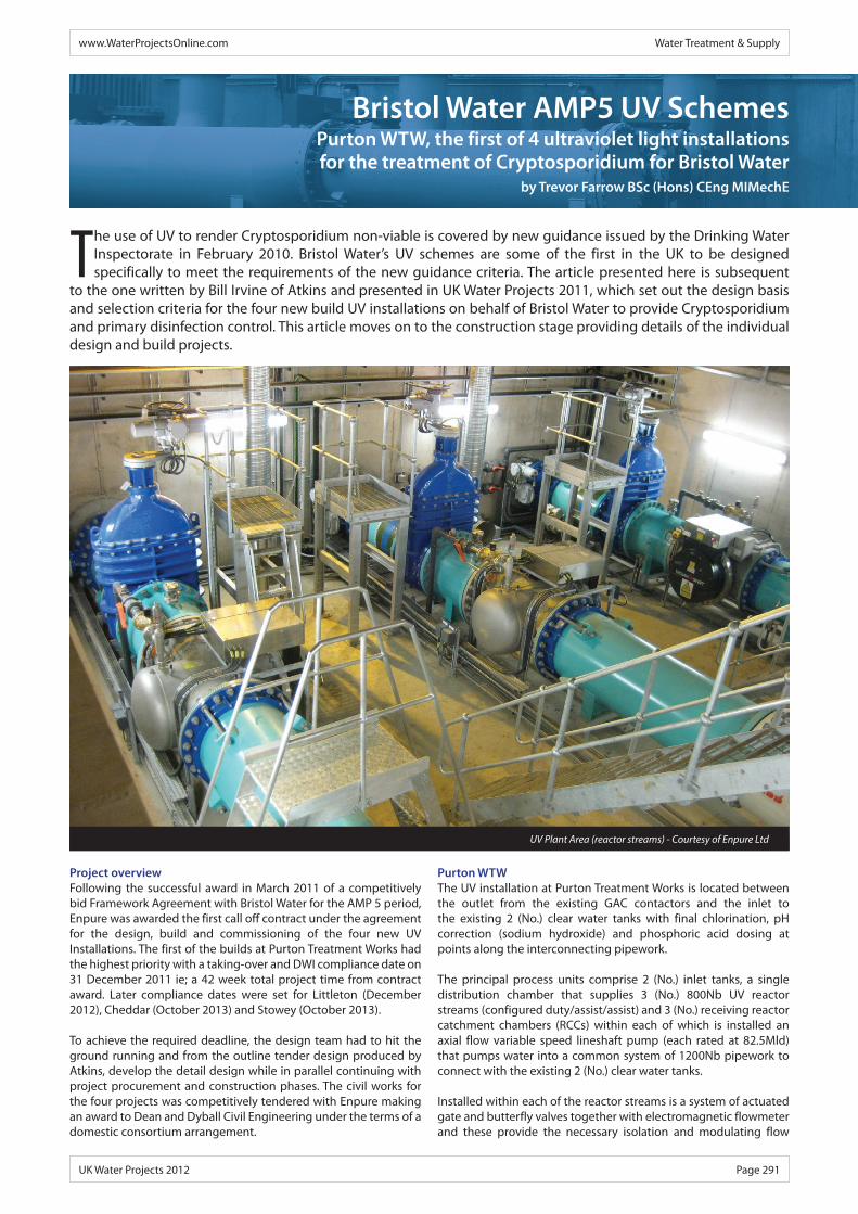
The principal process units comprise 2 (No.) inlet tanks, a single distribution chamber that supplies 3 (No.) 800Nb UV reactor streams (configured duty/assist/assist) and 3 (No.) receiving reactor catchment chambers (RCCs) within each of which is installed an axial flow variable speed lineshaft pump (each rated at 82.5Mld) that pumps water into a common system of 1200Nb pipework to connect with the existing 2 (No.) clear water tanks.
Installed within each of the reactor streams is a system of actuated gate and butterfly valves together with electromagnetic flowmeter and these provide the necessary isolation and modulating flow
www.WaterProjectsOnline.com Water Treatment & Supply
UK Water Projects 2012 Page 291
UV Plant Area (reactor streams) - Courtesy of Enpure Ltd

Sustainable solutions for the built and natural environment>Atkins is one of the world’s leading engineering and design consultancies.
We have the breadth and depth of expertise to respond to the most technically challenging and time critical infrastructure projects.
We support the water, wastewater and water-related environmental sectors with services from water strategy planning and flood management to infrastructure design and maintenance as well as providing consultancy and modelling services relating to coastal water, mitigating climate change impacts and managing water resource.
Atkins works all over the world delivering sustainable solutions to meet the complex challenges facing the water sector. We offer a holistic approach to the whole water lifecycle from assessment and design to project management and construction supervision.
Contact us at:
Sustainable water resources, China Atkins implemented a national water sector strategy; managed water pollution to improve water quality; developed a system to better manage land-use and natural resources; and integrated river basin management and environmental sustainability.
www.atkinsglobal.com/water
Water Treatment & Supply www.WaterProjectsOnline.com
Page 292 UK Water Projects 2012
control respectively. The dual valve arrangement after the UV reactors is a requirement to ensure there is no flow of untreated water when the reactor is off line. When off line, the isolated section of pipe between the reactor outlet valve and the RCC inlet valve is drained and monitored for being empty using ‘vibronic’ level sensors.
UV plantThe UV plant for each of the four treatment works has been supplied by Trojan Technologies and is based on their Swift 10L30 UV reactors. With the exception of Purton, which is a three stream arrangement, the other three plants are two stream units although each utilises exactly the same reactor model.
The number of streams in operation at any one time depends on the works flow and UV transmittance conditions. As the UV transmittance reduces, the maximum throughput of each UV reactor is reduced in order to maintain the required UV dose. It is under these conditions where the assist stream will be brought into service to maintain sufficient UV dose at higher works flows. The inlet UV transmittance to the plant is monitored by two UVT analysers with the sample taken from the point in the process upstream of the plant and must be above 74.2% to meet the minimum reactor validation criteria to adequately treat the water.
Treatment criteria and plant controlThe UV reactors can only operate under the validated conditions specified and these are dependent on the following critical parameters.
• UV irradiance intensity as measured by sensors for each lamp.
• UV lamp status, all lamps must be operational - 10 (No.) per reactor.
• UV lamp age run hours are within manufacturer’s specification (9,000 hours).
• UV transmittance of the incoming water must be within the validation range of ≥74.2% .
• Turbidity of the incoming water must be within the validation range of ≤1.0 NTU.
• Maximum flow through the reactor must be within the validation range according to the UV transmittance of the incoming flow.
Control systemThe UV reactors have their own dedicated control systems which monitor individual plant performance and initiate the necessary control sequences for operation. Each reactor is controlled by means of a local control power panel (CPP). The PLC within the CPP utilises the “Calculated (Required) Dose Approach” by which the reactor power is adjusted to achieve the varying conditions for four log removal of viable cryptosporidium. The PLC receives a required dose value generated by a separate supervisory PLC based on the measured UVT and a look-up table. The power consumed by each reactor will be automatically adjusted at the CPP to achieve the target dose taking into account the maximum flow treatable by the reactor.
The separate supervisory PLC monitors all other plant control and is housed within a new separate motor control centre (MCC panel). Access to the plant control for configuration and diagnostics is done via HMIs within the respective ICA section of the MCC and the Trojan CPPs, with inter communication over ethernet connections between the supervisory PLC and the existing works PLCs. A SCADA station is installed in the main control room of the UV building. The RCC pumps and reactor actuated valves are controlled and monitored over a profibus DP communication network, all other pumps and valves use conventional hardwired I/O.
Wastewater & Drinking Water
Advanced UV Water Treatment SolutionsFrom small rural communities to large municipalities like Rotterdam and Paris, Trojan has effective UV-based solutions that address your water treatment needs. With over 30 years experience, and the largest installed base of UV systems, Trojan provides the products, service and technical expertise you need.
Key benefits of TrojanUV systems include:
• Environmentally-friendly UV light • Proven through validation • Disinfection performance is guaranteed for life• Reduced total operating cost
For drinking water, wastewater, and environmental contaminant treatment – the world is turning to Trojan.
www.trojanuv.com - Trojan Technologies UK - T. 0044.1905.771117 Get your free UV Information Brochure. Send e-mail to: [email protected]
Anz.UK-Waterprojects-126x176.indd 1 24.08.2012 11:07:02
www.WaterProjectsOnline.com Water Treatment & Supply
UK Water Projects 2012 Page 293
UV cleaning processThe 10 (No.) lamps installed within each of the UV reactors are manufactured from quartz and are fitted within quartz sleeves.
Both the lamp sleeves and reference sensor sleeves are cleaned on a timed programmed basis using a mechanical/chemical cleaning system that consists of a wiper collar fitted to each of the lamps and which is filled with an ActiClean gel; an approved mild acid solution for potable water applications.
The wiper collars are fitted at each end with U-Cup seals and Teflon bearings and mounted onto a yoke by means of positive locking clips.
The yoke is moved by means of a magnetically coupled hydraulic drive comprising hydraulic power pack, 24volt dc permanent reversible motor, and pressure switches to control extension and retraction strokes. The wiper collars have fitted fill and drain connections for the ActiClean gel which is changed when a lamp change takes place at the validated 9,000 hours operation.
The degree of fouling within the reactors remains to be fully determined in the fullness of time, however provision has been made in the design for the introduction of temporary acid cleaning using low concentrations of phosphoric acid (25%) and citric acid solution (10%).
Ventilation considerationsTwo independent ventilation systems have been installed within the plant build. The first provides emergency ventilation of the low level plant area in the event of a mercury/mercury vapour emission.
Low pressure mercury vapour lamps provide the necessary germicidal wavelength of UV light and although there are only small amounts of mercury present, there is a risk of lamp breakage
during operation and transfer of contents through the process train. The design of the RCC tanks provides for capture of any entrained contents.
There is also the risk however of lamp breakage during maintenance and the potential exposure to operatives to an emission of mercury/mercury vapour.
For this reason, whenever a lamp breakage alarm occurs during operation the emergency ventilation system is brought into operation because the cause and effect may not be known until investigated local to the reactors and other plant items. A no risk approach therefore has been taken in the design.
The design of the general plant area ventilation has taken account of the amount of waste heat from the ballast panels installed in the MCC room and utilised this within an arrangement that provides for recirculation of warm air back to the plant area when external ambient temperatures are low and allows for cool air to be returned from the plant area back to the MCC room as ambient temperatures increase.
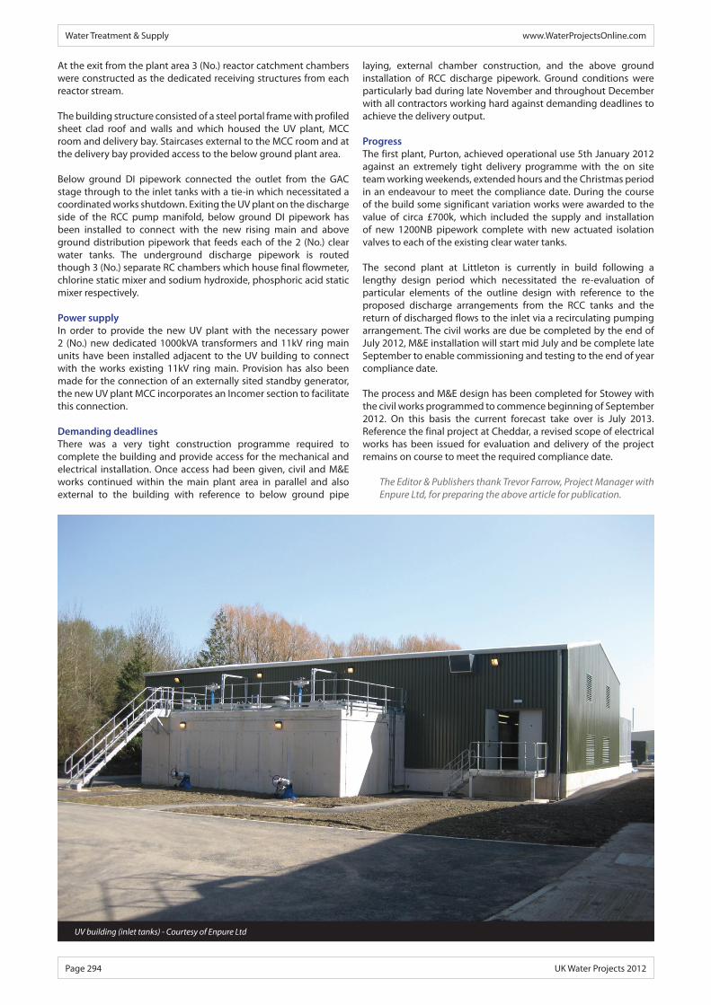
Civil worksThe main UV building accommodates the pipework and services supplying the process units, and it incorporates a ground slab constructed with in-situ concrete. As an integral part of the construction the ground slab also included sectioned areas for the MCC room and a delivery bay, each constructed on the opposite side of the main plant area respectively.
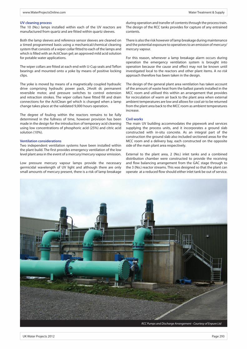
External to the plant area, 2 (No.) inlet tanks and a combined distribution chamber were constructed to provide the receiving and flow balancing arrangement from the GAC stage through to the 3 (No.) reactor streams. This was designed so that the plant can operate at a reduced flow should either inlet tank be out of service.
RCC Pumps and Discharge Arrangement - Courtesy of Enpure Ltd
At the exit from the plant area 3 (No.) reactor catchment chambers were constructed as the dedicated receiving structures from each reactor stream.
The building structure consisted of a steel portal frame with profiled sheet clad roof and walls and which housed the UV plant, MCC room and delivery bay. Staircases external to the MCC room and at the delivery bay provided access to the below ground plant area.
Below ground DI pipework connected the outlet from the GAC stage through to the inlet tanks with a tie-in which necessitated a coordinated works shutdown. Exiting the UV plant on the discharge side of the RCC pump manifold, below ground DI pipework has been installed to connect with the new rising main and above ground distribution pipework that feeds each of the 2 (No.) clear water tanks. The underground discharge pipework is routed though 3 (No.) separate RC chambers which house final flowmeter, chlorine static mixer and sodium hydroxide, phosphoric acid static mixer respectively.
Power supplyIn order to provide the new UV plant with the necessary power 2 (No.) new dedicated 1000kVA transformers and 11kV ring main units have been installed adjacent to the UV building to connect with the works existing 11kV ring main. Provision has also been made for the connection of an externally sited standby generator, the new UV plant MCC incorporates an Incomer section to facilitate this connection.
Demanding deadlinesThere was a very tight construction programme required to complete the building and provide access for the mechanical and electrical installation. Once access had been given, civil and M&E works continued within the main plant area in parallel and also external to the building with reference to below ground pipe
Water Treatment & Supply www.WaterProjectsOnline.com
Page 294 UK Water Projects 2012
laying, external chamber construction, and the above ground installation of RCC discharge pipework. Ground conditions were particularly bad during late November and throughout December with all contractors working hard against demanding deadlines to achieve the delivery output. ProgressThe first plant, Purton, achieved operational use 5th January 2012 against an extremely tight delivery programme with the on site team working weekends, extended hours and the Christmas period in an endeavour to meet the compliance date. During the course of the build some significant variation works were awarded to the value of circa £700k, which included the supply and installation of new 1200NB pipework complete with new actuated isolation valves to each of the existing clear water tanks.
The second plant at Littleton is currently in build following a lengthy design period which necessitated the re-evaluation of particular elements of the outline design with reference to the proposed discharge arrangements from the RCC tanks and the return of discharged flows to the inlet via a recirculating pumping arrangement. The civil works are due be completed by the end of July 2012, M&E installation will start mid July and be complete late September to enable commissioning and testing to the end of year compliance date.
The process and M&E design has been completed for Stowey with the civil works programmed to commence beginning of September 2012. On this basis the current forecast take over is July 2013. Reference the final project at Cheddar, a revised scope of electrical works has been issued for evaluation and delivery of the project remains on course to meet the required compliance date.
The Editor & Publishers thank Trevor Farrow, Project Manager with Enpure Ltd, for preparing the above article for publication.
UV building (inlet tanks) - Courtesy of Enpure Ltd