BridgePay P2PE Solution P2PE Instruction Manual v1
42
BridgePay P2PE Solution P2PE Instruction Manual v1.6 June 2021
Transcript of BridgePay P2PE Solution P2PE Instruction Manual v1

BridgePay P2PE Solution
P2PE Instruction Manual v1.6
June 2021

BridgePay P2PE Solution Instruction Manual v1.6
P2PE Instruction Manual for PCI P2PE v2.0 March 2021
© 2021 BridgePay Network Solutions, LLC. PIM Page 2
Table of Contents
1. P2PE Solution Information and Solution Provider Contact Details ................................................... 4
1.1 P2PE Solution Information ........................................................................................................ 4
1.2 Solution Provider Contact Information ...................................................................................... 4
P2PE and PCI DSS ............................................................................................................................... 4
2. Approved POI Devices, Applications/Software, and the Merchant Inventory ................................... 5
2.1 POI Device Details ........................................................................................................................... 5
2.2 POI Software/application Details ..................................................................................................... 8
2.3 POI Inventory & Monitoring ............................................................................................................ 13
3. POI Device Installation Instructions ................................................................................................ 16
Do not connect non-approved cardholder data capture devices. ........................................................ 16
Do not change or attempt to change device configurations or settings. .............................................. 16
3.1 Installation and connection instructions ......................................................................................... 17
Physically secure POI devices in your possession, including devices: ............................................... 23
3.2 Guidance for selecting appropriate locations for deployed devices .............................................. 23
3.3 Guidance for physically securing deployed devices to prevent unauthorized removal or
substitution ........................................................................................................................................... 24
4. POI Device Transit .......................................................................................................................... 25
4.1 Instructions for securing POI devices intended for, and during, transit ......................................... 25
4.2 Instructions for ensuring POI devices originate from, and are only shipped to, trusted
sites/locations ...................................................................................................................................... 26
Securing Devices Removed from Service ........................................................................................... 27
5. POI Device Tamper Monitoring and Skimming Prevention ............................................................ 28
5.1 Instructions for physically inspecting POI devices and preventing skimming, including instructions
and contact details for reporting any suspicious activity ...................................................................... 28
5.2 Instructions for responding to evidence of POI device tampering ................................................. 29
5.3 Instructions for confirming device and packaging were not tampered with, and for establishing
secure, confirmed communications with the solution provider ............................................................ 29
5.4 Provide guidance for the merchant to confirm the business need for, and identities of, any third-
party personnel claiming to be support or repair personnel, prior to granting those personnel access
to POI devices. ..................................................................................................................................... 33
6. Device Encryption Issues ................................................................................................................ 34
6.1 Instructions for responding to POI device encryption failures ....................................................... 34
6.2 Instructions for formally requesting of the P2PE solution provider that P2PE encryption of account
data be stopped ................................................................................................................................... 34
7. POI Device Troubleshooting ........................................................................................................... 35

BridgePay P2PE Solution Instruction Manual v1.6
P2PE Instruction Manual for PCI P2PE v2.0 March 2021
© 2021 BridgePay Network Solutions, LLC. PIM Page 3
7.1 Instructions for troubleshooting a POI device ................................................................................ 35
8. Additional Solution Provider Information ......................................................................................... 37
Disposal of Devices ............................................................................................................................. 37
Glossary of Terms ................................................................................................................................ 37
9. Appendix A – P2PE-Opt out Form .................................................................................................. 39
10. Appendix B – Images of Tampered devices .............................................................................. 40
Revision History ....................................................................................................................................... 42

BridgePay P2PE Solution Instruction Manual v1.6
P2PE Instruction Manual for PCI P2PE v2.0 March 2021
© 2021 BridgePay Network Solutions, LLC. PIM Page 4
1. P2PE Solution Information and Solution Provider Contact Details
1.1 P2PE Solution Information
Solution name: BridgePay P2PE Solution
Solution reference number per PCI SSC
website: 2019-00531.001
1.2 Solution Provider Contact Information
Company name: BridgePay Network Solutions
Company address: 1071 S. SUN DRIVE, SUITE 2002 LAKE MARY, FL 32746
Company URL: www.bridgepaynetwork.com
Contact name: Jared Carpenter
Contact phone number: 800-322-9894
Contact e-mail address: [email protected]
P2PE and PCI DSS
Merchants using this P2PE Solution may be required to validate PCI DSS compliance and should be
aware of their applicable PCI DSS requirements. Merchants should contact their acquirer or payment
brands to determine their PCI DSS validation requirements.

BridgePay P2PE Solution Instruction Manual v1.6
P2PE Instruction Manual for PCI P2PE v2.0 March 2021
© 2021 BridgePay Network Solutions, LLC. PIM Page 5
2. Approved POI Devices, Applications/Software, and the Merchant Inventory
2.1 POI Device Details
The following information lists the details of the PCI-approved POI devices approved for use in this P2PE solution.
Note all POI device information can be verified by visiting:
https://www.pcisecuritystandards.org/approved_companies_providers/approved_pin_transaction_security.php
POI device vendor: PAX Computer Technology (Shenzhen) Co Ltd
POI device model name and number: A920
Hardware version #(s): A920-xxx-0x5-0xxx, (Non CTLS), A920-xxx-Rx5-0xxx (CTLS),
A920-xxx-0x5-1xxx, A920-xxx-Rx5-1xxx (CTLS), A920-xxx-
0x5-2xxx, A920-xxx-Rx5-2xxx
Firmware version #(s): 25.00.xxxx, 25.01.xxxx
PCI PTS Approval #(s): 4-40215
POI device vendor: Ingenico, Inc
POI device model name and number: iSC Touch 250
Hardware version #(s): iSC2xx-21Txxxxx, iSC2xx-31Txxxxx
Firmware version #(s): 820518 V12.xx, SRED (CTLS): 820528V02.xx
PCI PTS Approval #(s): 4-30132
BridgePay P2PE Solution Instruction Manual v1.6
P2PE Instruction Manual for PCI P2PE v2.0 March 2021
© 2021 BridgePay Network Solutions PIM Page 6
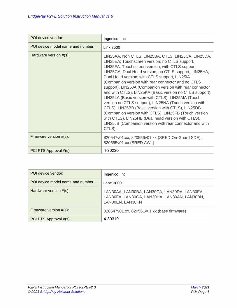
POI device vendor: Ingenico, Inc
POI device model name and number: Link 2500
Hardware version #(s): LIN25AA, Non CTLS, LIN25BA, CTLS, LIN25CA, LIN25DA,
LIN25EA; Touchscreen version; no CTLS support,
LIN25FA; Touchscreen version; with CTLS support,
LIN25GA; Dual Head version; no CTLS support, LIN25HA;
Dual Head version; with CTLS support, LIN25IA
(Companion version with rear connector and no CTLS
support), LIN25JA (Companion version with rear connector
and with CTLS), LIN25KA (Basic version no CTLS support),
LIN25LA (Basic version with CTLS), LIN25MA (Touch
version no CTLS support), LIN25NA (Touch version with
CTLS), LIN25BB (Basic version with CTLS), LIN25DB
(Companion version with CTLS), LIN25FB (Touch version
with CTLS), LIN25HB (Dual head version with CTLS),
LIN25JB (Companion version with rear connector and with
CTLS)
Firmware version #(s): 820547v01.xx, 820556v01.xx (SRED On-Guard SDE),
820555v01.xx (SRED AWL)
PCI PTS Approval #(s): 4-30230
POI device vendor: Ingenico, Inc
POI device model name and number: Lane 3000
Hardware version #(s): LAN30AA, LAN30BA, LAN30CA, LAN30DA, LAN30EA,
LAN30FA, LAN30GA, LAN30HA, LAN30AN, LAN30BN,
LAN30EN, LAN30FN
Firmware version #(s): 820547v01.xx, 820561v01.xx (base firmware)
PCI PTS Approval #(s): 4-30310

BridgePay P2PE Solution Instruction Manual v1.6
P2PE Instruction Manual for PCI P2PE v2.0 March 2021
© 2021 BridgePay Network Solutions PIM Page 7
POI device vendor: Ingenico, Inc
POI device model name and number: Lane 7000
Hardware version #(s): LAN70AA, LAN70AB
Firmware version #(s): 820547v01.xx
PCI PTS Approval #(s): 4-30237
POI device vendor: Ingenico, Inc
POI device model name and number: Lane 8000
Hardware version #(s): LAN80AA
Firmware version #(s): 820547v01.xx
PCI PTS Approval #(s): 4-30257
POI device vendor: Ingenico, Inc
POI device model name and number: Move 5000
Hardware version #(s): MOV50AB, (Non CTLS), MOV50BB, (CTLS), MOV50CB,
(Non CTLS + Privacy shield), MOV50DB, (CTLS + Privacy
shield), MOV50JB (CTLS + Privacy shield + Desktop case
lid), MOV50AC (Non CTLS), MOV50BC (CTLS),
MOV50CC (Non CTLS + Privacy shield), MOV50DC (CTLS
+ Privacy shield), MOV50JC (CTLS + Privacy shield +
Desktop case lid), MOV50AQ (Non CTLS), MOV50BQ
(CTLS), MOV50CQ (Non CTLS + Privacy shield),
MOV50DQ (CTLS + Privacy shield), MOV50JQ (CTLS +
Privacy shield + Desktop case lid), MOV50AS (Non CTLS),
MOV50BS (CTLS), MOV50CS (Non CTLS + Privacy
shield), MOV50DS (CTLS + Privacy shield), MOV50JS
(CTLS + Privacy shield + Desktop case lid)
Firmware version #(s): 820547v01.xx, 820376v01.xx, 820555v01.xx (SRED),
820549v01.xx (SRED OnGuard FPE), 820556v01.xx
(SRED OnGuard SDE), 820559v01.xx (SRED ANL),
820565v01.xx (SRED FF1)
PCI PTS Approval #(s): 4-20316
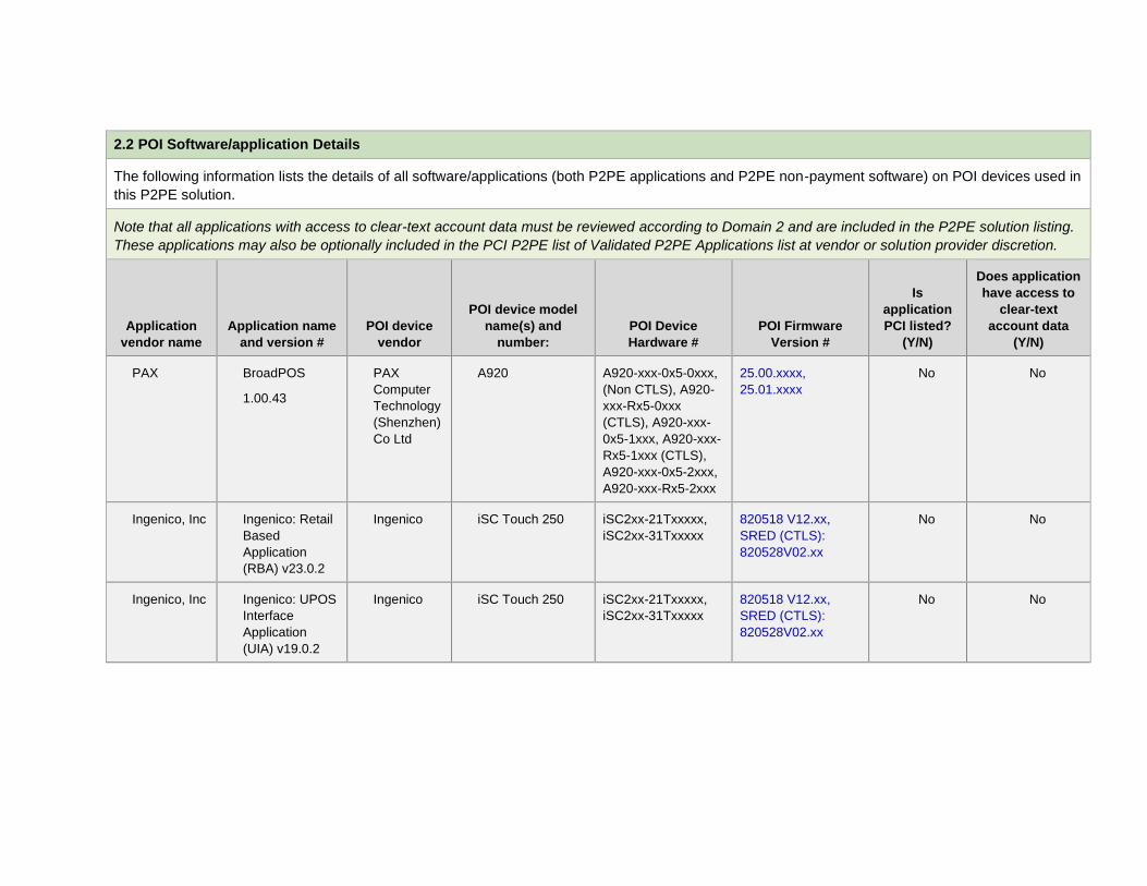
2.2 POI Software/application Details
The following information lists the details of all software/applications (both P2PE applications and P2PE non-payment software) on POI devices used in
this P2PE solution.
Note that all applications with access to clear-text account data must be reviewed according to Domain 2 and are included in the P2PE solution listing.
These applications may also be optionally included in the PCI P2PE list of Validated P2PE Applications list at vendor or solution provider discretion.
Application
vendor name
Application name
and version #
POI device
vendor
POI device model
name(s) and
number:
POI Device
Hardware #
POI Firmware
Version #
Is
application
PCI listed?
(Y/N)
Does application
have access to
clear-text
account data
(Y/N)
PAX BroadPOS
1.00.43
PAX
Computer
Technology
(Shenzhen)
Co Ltd
A920 A920-xxx-0x5-0xxx,
(Non CTLS), A920-
xxx-Rx5-0xxx
(CTLS), A920-xxx-
0x5-1xxx, A920-xxx-
Rx5-1xxx (CTLS),
A920-xxx-0x5-2xxx,
A920-xxx-Rx5-2xxx
25.00.xxxx,
25.01.xxxx
No No
Ingenico, Inc Ingenico: Retail
Based
Application
(RBA) v23.0.2
Ingenico iSC Touch 250 iSC2xx-21Txxxxx,
iSC2xx-31Txxxxx
820518 V12.xx,
SRED (CTLS):
820528V02.xx
No No
Ingenico, Inc Ingenico: UPOS
Interface
Application
(UIA) v19.0.2
Ingenico iSC Touch 250 iSC2xx-21Txxxxx,
iSC2xx-31Txxxxx
820518 V12.xx,
SRED (CTLS):
820528V02.xx
No No

BridgePay P2PE Solution Instruction Manual v1.6
P2PE Instruction Manual for PCI P2PE v2.0 March 2021
© 2021 BridgePay Network Solutions PIM Page 9
Application
vendor name
Application name
and version #
POI device
vendor
POI device model
name(s) and
number:
POI Device
Hardware #
POI Firmware
Version #
Is
application
PCI listed?
(Y/N)
Does application
have access to
clear-text
account data
(Y/N)
Ingenico, Inc Unified Payment
Application
(UPP)
2.0.x
Ingenico Link 2500 LIN25AA, Non
CTLS, LIN25BA,
CTLS, LIN25CA,
LIN25DA, LIN25EA;
Touchscreen
version; no CTLS
support, LIN25FA;
Touchscreen
version; with CTLS
support, LIN25GA;
Dual Head version;
no CTLS support,
LIN25HA; Dual
Head version; with
CTLS support,
LIN25IA
(Companion version
with rear connector
and no CTLS
support), LIN25JA
(Companion version
with rear connector
and with CTLS),
LIN25KA (Basic
version no CTLS
support), LIN25LA
(Basic version with
CTLS), LIN25MA
(Touch version no
CTLS support),
LIN25NA (Touch
version with CTLS),
LIN25BB (Basic
version with CTLS),
820547v01.xx,
820556v01.xx
(SRED On-Guard
SDE), 820555v01.xx
(SRED AWL)
Yes No

BridgePay P2PE Solution Instruction Manual v1.6
P2PE Instruction Manual for PCI P2PE v2.0 March 2021
© 2021 BridgePay Network Solutions PIM Page 10
LIN25DB
(Companion version
with CTLS),
LIN25FB (Touch
version with CTLS),
LIN25HB (Dual head
version with CTLS),
LIN25JB
(Companion version
with rear connector
and with CTLS)
Application
vendor name
Application name
and version #
POI device
vendor
POI device model
name(s) and
number:
POI Device
Hardware #
POI Firmware
Version #
Is
application
PCI listed?
(Y/N)
Does application
have access to
clear-text
account data
(Y/N)
Ingenico, Inc Unified Payment
Application
(UPP)
2.0.x
Ingenico Lane 3000 LAN30AA,
LAN30BA,
LAN30CA,
LAN30DA,
LAN30EA,
LAN30FA,
LAN30GA,
LAN30HA,
LAN30AN,
LAN30BN,
LAN30EN,
LAN30FN
820547v01.xx,
820561v01.xx (base
firmware)
Yes No
Ingenico, Inc Unified Payment
Application
(UPP)
2.0.x
Ingenico Lane 7000 LAN70AA,
LAN70AB
820547v01.xx Yes No
Ingenico, Inc Unified Payment
Application
(UPP)
2.0.x
Ingenico Lane 8000 LAN80AA 820547v01.xx Yes No

BridgePay P2PE Solution Instruction Manual v1.6
P2PE Instruction Manual for PCI P2PE v2.0 March 2021
© 2021 BridgePay Network Solutions PIM Page 11
Application
vendor name
Application name
and version #
POI device
vendor
POI device model
name(s) and
number:
POI Device
Hardware #
POI Firmware
Version #
Is
application
PCI listed?
(Y/N)
Does application
have access to
clear-text
account data
(Y/N)
Ingenico, Inc Unified Payment
Application
(UPP)
2.0.x
Ingenico Move 5000 MOV50AB, (Non
CTLS), MOV50BB,
(CTLS), MOV50CB,
(Non CTLS +
Privacy shield),
MOV50DB, (CTLS +
Privacy shield),
MOV50JB (CTLS +
Privacy shield +
Desktop case lid),
MOV50AC (Non
CTLS), MOV50BC
(CTLS), MOV50CC
(Non CTLS +
Privacy shield),
MOV50DC (CTLS +
Privacy shield),
MOV50JC (CTLS +
Privacy shield +
Desktop case lid),
MOV50AQ (Non
CTLS), MOV50BQ
(CTLS), MOV50CQ
(Non CTLS +
Privacy shield),
MOV50DQ (CTLS +
Privacy shield),
MOV50JQ (CTLS +
Privacy shield +
820547v01.xx,
820376v01.xx,
820555v01.xx
(SRED),
820549v01.xx
(SRED OnGuard
FPE), 820556v01.xx
(SRED OnGuard
SDE), 820559v01.xx
(SRED ANL),
820565v01.xx
(SRED FF1)
Yes No

BridgePay P2PE Solution Instruction Manual v1.6
P2PE Instruction Manual for PCI P2PE v2.0 March 2021
© 2021 BridgePay Network Solutions PIM Page 12
Desktop case lid),
MOV50AS (Non
CTLS), MOV50BS
(CTLS), MOV50CS
(Non CTLS +
Privacy shield),
MOV50DS (CTLS +
Privacy shield),
MOV50JS (CTLS +
Privacy shield +
Desktop case lid)

2.3 POI Inventory & Monitoring
▪ All POI devices must be documented via inventory control and monitoring procedures, including
device status (deployed, awaiting deployment, undergoing repair or otherwise not in use, or in
transit).
▪ This inventory must be performed annually, at a minimum.
▪ Any variances in inventory, including missing or substituted POI devices, must be reported to
BridgePay via the contact information in Section 1.2 above.
▪ Sample inventory table below is for illustrative purposes only. The actual inventory should be
captured and maintained by the merchant in an external document.
In order for you to maintain your compliance you must maintain an inventory of the provided POI devices.
You must track which devices are deployed, which are awaiting deployment, those that have been removed
from service for repair or otherwise not in use, and those in transit for deployment or return for repair. It is
recommended that you designate an employee to be responsible for maintaining the POI inventory and for
inspection of devices.
For each area identified the following information must be recorded. It is mandatory that you record this
information upon receipt of your POI device and then update the location of each device as it transitions
from storage, transit, deployment, and repair or return.
• Manufacturer of device;
• Make and Model of device;
• Serial Number of Device;
• Internal Inventory Number; (if applicable);
• General Description of Device (Color, Secure Seals, Labels, Hidden Marking, etc.);
• Number and type of physical connections (Network, Serial, etc)
• Firmware version;
• Hardware version;
• Device Location (Storage, Where Deployed, In Transit, Awaiting Repairs or Returned);
• Date of Location Inspection (Last Date device location was confirmed);
• Date of Last Inspection (last date device was inspected for tampering);
• Name of Job Role or personnel performing inspection; and
• Date inventory was last updated
Device identification can be found on the PTS POI device itself. Generally, this information is contained
upon a manufacturer provided label located on the back or side of the device.
Device inventories are to be performed no less than annually to confirm that inventory of devices is being
catalogued and performed correctly; however, inventory must be updated as device transition in and out of
service and from one location to another. This inventory must also be completed to confirm that all devices
identified as being within your environment are currently within your possession and not missing.
Access to device inventory and to the devices themselves must be restricted to authorized personnel. The
method for maintaining a device inventory is determined by you; however, the method utilized must enable
you to restrict access to the inventory tracking information and allow you to record who has had access to
the inventory tracking information. Failure to do so will impact your PCI DSS compliance. In addition, you

BridgePay P2PE Solution Instruction Manual v1.6
P2PE Instruction Manual for PCI P2PE v2.0 March 2021
© 2021 BridgePay Network Solutions PIM Page 14
must be able to restrict access to stored devices and record who has accessed said devices and when
access occurred.
During your inventory process, you must investigate the POI devices to identify unauthorized removal,
tampering, or substitution of devices. Detection of these events may be an indication of a compromise of
your environment. Inspection of device should compare information located on the device itself with the
inventory information previously recorded. In addition, the inspection should look for indications that the
device has been tampered with. Indications of tampering may include, but is not limited to, attachment of
unauthorized devices to the POI device, breakage of security seals, cracks within the seal of the device
itself, or insertion of a “skimmer” device within the Magnetic Stripe Reader (MSR) of the device. Skimmers
are devices used by attackers to capture cardholder data prior to the POI device reading the card.
Skimmers may be inserted in the MSR of the device or overlaid on the device itself. It is recommended that
you train personnel (Cashiers/Managers) interfacing with the POI devices on a regular basis to inspect
deployed POI devices daily.
Should you detect a compromised device or find that your inventory indicated a missing or substituted
device, you must report this information to the sender immediately.
For device being stored be it prior to deployment, shipment, or awaiting repairs, they must be stored in a
secure area with restricted access to ensure they are not tampered with. Though the storage location of
devices within your control is your responsibility, the location must include the following measures:
1) Device must be stored in locked room or container; 2) Storage location must support restricted access; 3) Must restrict access to authorized personnel. Example include:
a. Door/Container requiring key access in which defined personnel have access to the key; or
b. Door/Container required knowledge of cipherlock code in which defined personnel have knowledge of the cipherlock code.
4) Access to room or container storing device must be logged. This logging may be manual (written access log) or automatic (proximity card system that records access);
5) Access to room must be monitored (Cameras or physical sight).
In addition to keeping records of all device serial numbers and updating as needed, please follow the
guidelines below. This includes installed devices and devices in storage.
• Take photographs from all angles of each device, including any labels or serial numbers on the
device.
• Use the original photographs to compare the devices on future inventory reviews. If the devices
appear to be tampered with, please contact your Solution provider immediately.
• Record the location a device is deployed and match to the device serial number
• Record the exact details of any security labels on the device
• Record how the terminal is connected, including the style, type, and color of each connector. A
photograph of the connectors is recommended.
• Mark each terminal with an ultra-violet (UV) security pen to provide a unique identifier for that
terminal.
A sample inventory table is provided on the following page.

Sample Inventory Table
Name of
Employee
Performing
Inspection John Smith
Date of
Inspection: 10-21-2017
Device
vendor
Device Make
& Model: Firmware Version
Hardware
Version
Device
Location
and status
Device Status
Confirm Date
Serial
Number &
Internal
Tracking
Number
Device
Description
and
supported
connections
Device
Inspection
Date
Ingenico iSC Touch
250 820518
V12.xx, SRED
(CTLS):
820528V02.xx
iSC2xx-
21Txxxxx,
iSC2xx-
31Txxxxx
Store 1
installed
02-05-2019 907987 USB
Black
03-05-
2019

3. POI Device Installation Instructions
Do not connect non-approved cardholder data capture devices.
The P2PE solution is approved to include specific PCI-approved POI devices. Only these devices
denoted above in table 2.1 are allowed for cardholder data capture.
If a merchant’s PCI-approved POI device is connected to a data capture mechanism that is not PCI
approved, (for example, if a PCI-approved SCR was connected to a keypad that was not PCI-
approved):
▪ The use of such mechanisms to collect PCI payment-card data could mean that more PCI DSS
requirements are now applicable for the merchant.
▪ Only P2PE approved capture mechanisms as designated on PCI’s list of Validated P2PE Solutions and
in the PIM can be used.
Do not change or attempt to change device configurations or settings.
Changing or attempting to change device configurations or settings will invalidate the PCI-
approved P2PE solution in its entirety. Examples include, but are not limited to:
▪ Attempting to enable any device interfaces or data-capture mechanisms that were disabled on the
P2PE solution POI device
▪ Attempting to alter security configurations or authentication controls
▪ Physically opening the device
▪ Attempting to install applications onto the device

BridgePay P2PE Solution Instruction Manual v1.6
P2PE Instruction Manual for PCI P2PE v2.0 March 2021
© 2021 BridgePay Network Solutions PIM Page 17
3.1 Installation and connection instructions
It is imperative that you follow the guidelines detailed below for the deployment of the P2PE solution.
Failure to do so may impact your PCI DSS compliance and the protections afforded to you by the P2PE
solution.
Prior to deployment, you must understand that any modification to the deployment can and will impact
your compliance. Such modifications may include:
o Attempting to enable any device interfaces or data-capture mechanisms that were
disabled on the P2PE solution POI device
o Attempting to alter security configurations or authentication controls
o Physically opening the device
o Attempting to install applications onto the device
Also, understand if a PCI-approved POI component is connected to another device or data-capture
mechanism, the non-PCI-approved capture mechanism is not secured by the P2PE solution, and the
use of any such mechanisms to collect PCI payment-card data would negate any PCI DSS scope
reduction which might otherwise have been provided by the P2PE solution’s device.
The P2PE solution provided by BridgePay or our partners only includes those devices previously
identified in section 2.2 of this manual. It does not allow for POI components that are not PCI approved.
Ingenico Device - PayGuardian Desktop Installation
NOTE: PayGuardian Desktop and PayGuardian Cloud only supports Ingenico with UIA software
loaded on the terminal. Ensure you have the correct terminal load. PayGuardian does not support
RBA terminal loads.
The first step is to install the BridgePay POI BridgePay software on a supported O/S (Windows 7 SP1
or later). To install simply double click on the BridgePay POI Bridge Microsoft Installer Program
downloaded from our support site. This will setup the bridge software that enables communication with
the POI device to our P2PE gateway. Once this is installed you will need to connect your POI device.
Only those POI devices listed in section 2.2 of this guide are supported. Based on the type of POI device
you selected, will determine needed POI device to BridgePay POI Bridge software connectivity steps.
Ingenico iSC250 - PayGuardian Cloud
Viewsonic Network Appliance (VNA) needs to be installed in merchant location and connected to the
same network as the terminal(s).
The (VNA) is provided by the reseller.
The VNA is preconfigured with a UUID.
Terminal manager (reseller) registers the VNA UUID with the PG Cloud service.
For POI devices using Serial or USB connectivity to the system running the BridgePay POI Bridge
Software, connect the POI device to the workstation prior to powering on the device. Once the POI
device is connected, plug in the device’s power cord. The POI device will power up and the POI device
and the bridge software will sync.

BridgePay P2PE Solution Instruction Manual v1.6
P2PE Instruction Manual for PCI P2PE v2.0 March 2021
© 2021 BridgePay Network Solutions PIM Page 18
For POI devices using BlueTooth connectivity to the system running the BridgePay POI Bridge Software,
you will need to enable BlueTooth on your workstation and pair the POI device to the workstation. Once
you have a successful pairing, start up the BridgePay POI Bridge Software. The bridge software and
the POI device will sync.
For POI Devices using the network (Ethernet or WiFi) to communicate to the system running the
BridgePay POI Bridge software, you will need to connect the POI device to your network first. For WiFi,
you will need to enter in the WiFi network parameters into the POI device to include the SSID and WiFi
password. Note: your WiFi should be set to WPA2 or stronger parameters to meet PCI DSS requirement.
For Ethernet, connect an Ethernet cable to the device and power on the device. You will need to enter
a Static IP address into the POI Device. In the BridgePay POI Bridge software, you must define the ip-
address and device type within the device settings interface of the software. Once defined, the software
will sync with the POI device.
If no error message appears on the bridge software or the POI device screen, then installation is
complete and you may proceed with accepting of payments. If a connection error appears on the screen
after connecting the device to your network and powering on, please contact BridgePay support.
Ingenico Device – PayGuardian Android
NOTE: PayGuardian Android only supports Ingenico with RBA software loaded on the terminal.
Ensure you have the correct terminal load. PayGuardian Android does not support UIA terminal
loads.
The first step is to install your compatible payment application on a supported O/S. The steps to install
the payment software is supplied by the integrator or manufacturer. See the documentation that was
provided with that solution.
This will setup the bridge software that enables communication with the POI device to our P2PE gateway.
Once this is installed you will need to connect your POI device. Only those POI devices listed in section
2.2 of this guide are supported. Based on the type of POI device you selected, will determine needed
POI device to BridgePay POI Bridge software connectivity steps.
PAX A920
Integrations using the PAX A920 POI device do not utilize PayGuardian.
The PAX A920 terminal utilizes the PAXStore an online secure marketplace to download compatible
applications. An application installed on the terminal provides access to the PAXStore and manages the
downloads.
This document assumes the PAXStore and BroadPOS applications are currently configured for a reseller
and is configured for access to the BridgePay Gateway.
For POI Devices using WiFi to communicate, you will need to connect the POI device to your network
first. For WiFi, you will need to enter in the WiFi network parameters into the POI device to include the
SSID and WiFi password. Note: your WiFi should be set to WPA2 or stronger parameters to meet PCI
DSS requirement.
Accessing Transaction Settings and Changing Default Passwords

BridgePay P2PE Solution Instruction Manual v1.6
P2PE Instruction Manual for PCI P2PE v2.0 March 2021
© 2021 BridgePay Network Solutions PIM Page 19
If you need to perform any administrative activities to the terminal after downloading an application you may need to access the transactions settings screens. You can run your payment application to access and customize some, but not all, of the transaction settings.
NOTE: To avoid potential issues, changes to the terminal should be managed through the application in PAXSTORE (http://www.pax.us/app-store/), not in the terminal. Accessing the Settings option from the Android home screen provides access to the standard Android options such as Wireless and Networks, Device Options, Personal Preferences, System Options, etc. NOTE: The default password for android settings must be changed upon receiving the device and before utilizing the device in a production environment to meet PCI DSS requirements.
If you have any issues connecting your POI devices, installing the software, or configuring the software,
please contact BridgePay Support.
Ingenico – Link 2500
Contents of the Box
• Link 2500 Terminal Unit
• User Guide
• Power Adapters (U.S. and International)
• USB Charging Cable with USB-C (smaller end) and USB-A connector (larger end)
Charging the Link 2500
• There is a USB-C connector on the right side of the wireless terminal.
• Plug the USB cable - USB-C connector to the right side of the terminal
• Slide the U.S. power adapter on the power supply.
• Connect the USB cable - USB-A connector to the power supply
• Plug the power supply into a power outlet
NOTE: On initial set-up, charge the battery for 4 hours. Subsequent charges should only
take 1.5 hours
Power the Link 2500 ON / OFF
• Turn on the terminal by holding down the green button
• Turn off the terminal by holding down the .,#* and yellow key at the same time until the screen
shows “Shutdown in Progress”
Connecting the Link 2500 via WiFi
• Type 2, 6, 3, 4 on the terminal.
• Press F for menu
• Press F3 scroll to Tetra Admin
• Press F3 to scroll down to Configure WiFi
• Enable WiFi by pressing the green button
• Select Scan Networks

BridgePay P2PE Solution Instruction Manual v1.6
P2PE Instruction Manual for PCI P2PE v2.0 March 2021
© 2021 BridgePay Network Solutions PIM Page 20
• You will see a list of available networks. Select your WiFi network. Press the green button.
• Enter the WiFi password. Press the green button
NOTE: Yellow button goes back one screen.
Connecting (paring) the Link 2500 via Bluetooth
• Enable Bluetooth on your base station such as an iPad
• Type 2, 6, 3, 4 on the terminal. You should see a menu displayed.
• Press F3 to scroll down to the Bluetooth settings
• Press the green button
• Select Pair
• On the base station (iPad), select the Link 2500
• Press the green button on the terminal to complete the paring
Ingenico – Lane 3000
Contents of the Box
• Lane 3000 Terminal Unit
• User Guide
• Power Cable (if ordered with the terminal, specific to connectivity requirements)
o Power supply unit and power cord
o The Lane 3000 terminal can be powered by several ways:
▪ An external power supply unit (modular & non modular) limited to PS2 type
▪ By USB (5VDC or 12VDC) (modular & non modular) limited to PS2 type
▪ By POE (Power over Ethernet) (modular)
• Stylus
• Mounting Screws
Connecting the Lane 3000
CAUTION
Connecting must be made when power supply unit is not plugged in the cable.
• Flip the terminal. There is one port on the back for power and communications.
• Connect the cable on the terminal.
• Connect the other end to the power supply unit and a Host (PC / cash register…)
• Plug the power supply into a power outlet
Ingenico – Lane 7000
Contents of the Box
• Lane 7000 terminal
• User guide
• Power Cable (if ordered with the terminal, specific to connectivity requirements)
o Power supply unit and power cord
o The Lane 7000 terminal can be powered by several ways:
▪ An external power supply unit

BridgePay P2PE Solution Instruction Manual v1.6
P2PE Instruction Manual for PCI P2PE v2.0 March 2021
© 2021 BridgePay Network Solutions PIM Page 21
▪ By USB (5VDC or 12VDC) (modular & non modular) limited to PS2 type
▪ By POE (Power over Ethernet) (modular)
• Stylus
• Mounting Screws
Connecting the Lane 7000
CAUTION
Connecting must be made when power supply unit is not plugged in the cable.
• Flip the terminal. There is one port on the back for power and communications.
• Connect the cable on the terminal.
• Connect the other end to the power supply unit and a Host (PC / cash register…)
• Plug the power supply into a power outlet
Ingenico – Lane 8000
Contents of the Box
• Lane 8000 terminal
• User guide
• Power Cable (if ordered with the terminal, specific to connectivity requirements)
o Power supply unit and power cord
o The Lane 8000 terminal can be powered by several ways:
▪ An external power supply unit
▪ By USB (5VDC or 12VDC) (modular & non modular) limited to PS2 type
▪ By POE (Power over Ethernet) (modular)
• Stylus
• Mounting Screws
Connecting the Lane 8000
CAUTION
Connecting must be made when power supply unit is not plugged in the cable.
• Flip the terminal. There is one port on the back for power and communications.
• Connect the cable on the terminal.
• Connect the other end to the power supply unit and a Host (PC / cash register…)
• Plug the power supply into a power outlet
Ingenico – Move 5000
Contents of the Box
• MOVE/5000 terminal unit equipped with a paper roll
• User Guide
• Power Adapter
Charging the Move 5000
BridgePay P2PE Solution Instruction Manual v1.6
P2PE Instruction Manual for PCI P2PE v2.0 March 2021
© 2021 BridgePay Network Solutions PIM Page 22
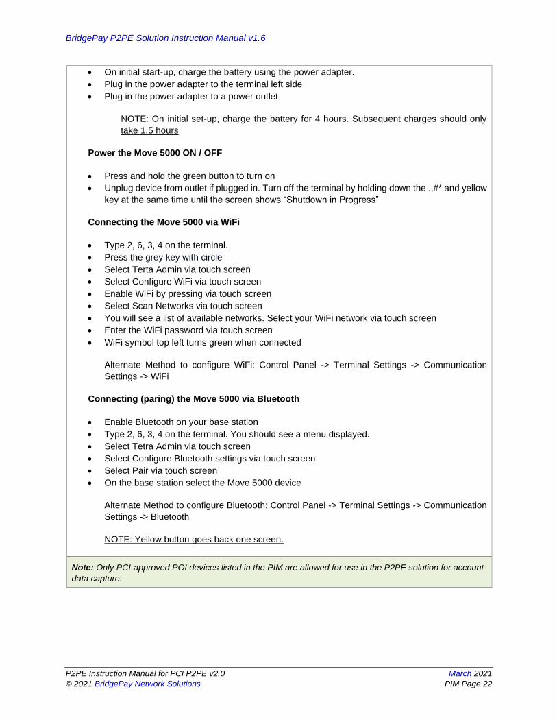
• On initial start-up, charge the battery using the power adapter.
• Plug in the power adapter to the terminal left side
• Plug in the power adapter to a power outlet
NOTE: On initial set-up, charge the battery for 4 hours. Subsequent charges should only
take 1.5 hours
Power the Move 5000 ON / OFF
• Press and hold the green button to turn on
• Unplug device from outlet if plugged in. Turn off the terminal by holding down the .,#* and yellow
key at the same time until the screen shows “Shutdown in Progress”
Connecting the Move 5000 via WiFi
• Type 2, 6, 3, 4 on the terminal.
• Press the grey key with circle
• Select Terta Admin via touch screen
• Select Configure WiFi via touch screen
• Enable WiFi by pressing via touch screen
• Select Scan Networks via touch screen
• You will see a list of available networks. Select your WiFi network via touch screen
• Enter the WiFi password via touch screen
• WiFi symbol top left turns green when connected
Alternate Method to configure WiFi: Control Panel -> Terminal Settings -> Communication
Settings -> WiFi
Connecting (paring) the Move 5000 via Bluetooth
• Enable Bluetooth on your base station
• Type 2, 6, 3, 4 on the terminal. You should see a menu displayed.
• Select Tetra Admin via touch screen
• Select Configure Bluetooth settings via touch screen
• Select Pair via touch screen
• On the base station select the Move 5000 device
Alternate Method to configure Bluetooth: Control Panel -> Terminal Settings -> Communication
Settings -> Bluetooth
NOTE: Yellow button goes back one screen.
Note: Only PCI-approved POI devices listed in the PIM are allowed for use in the P2PE solution for account
data capture.
BridgePay P2PE Solution Instruction Manual v1.6
P2PE Instruction Manual for PCI P2PE v2.0 March 2021
© 2021 BridgePay Network Solutions PIM Page 23
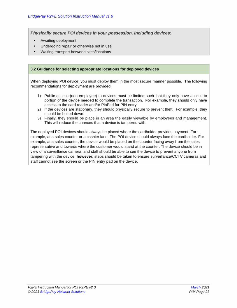
Physically secure POI devices in your possession, including devices:
▪ Awaiting deployment
▪ Undergoing repair or otherwise not in use
▪ Waiting transport between sites/locations.
3.2 Guidance for selecting appropriate locations for deployed devices
When deploying POI device, you must deploy them in the most secure manner possible. The following
recommendations for deployment are provided:
1) Public access (non-employee) to devices must be limited such that they only have access to portion of the device needed to complete the transaction. For example, they should only have access to the card reader and/or PinPad for PIN entry.
2) If the devices are stationary, they should physically secure to prevent theft. For example, they should be bolted down.
3) Finally, they should be place in an area the easily viewable by employees and management. This will reduce the chances that a device is tampered with.
The deployed POI devices should always be placed where the cardholder provides payment. For
example, at a sales counter or a cashier lane. The POI device should always face the cardholder. For
example, at a sales counter, the device would be placed on the counter facing away from the sales
representative and towards where the customer would stand at the counter. The device should be in
view of a surveillance camera, and staff should be able to see the device to prevent anyone from
tampering with the device, however, steps should be taken to ensure surveillance/CCTV cameras and
staff cannot see the screen or the PIN entry pad on the device.

BridgePay P2PE Solution Instruction Manual v1.6
P2PE Instruction Manual for PCI P2PE v2.0 March 2021
© 2021 BridgePay Network Solutions PIM Page 24
3.3 Guidance for physically securing deployed devices to prevent unauthorized removal or
substitution
If the devices are deployed in a remote location or unattended, it is recommended that the devices be
monitored with a camera so that one may review footage to determine if someone has attempted to
tamper with the device.
Though the provided devices from BridgePay can be physically mounted to reduce theft, if you deploy
a device where mounting is not possible, the device should not be left unattended. In addition, during
off-hours, the device should be move to a secure location to reduce chance of theft and/or tampering.
The deployed POI devices should be secured to the location to prevent movement. BridgePay
recommends purchasing a stand to physically bolt the device down and ensure that it cannot be
moved or tampered with. The cables on the certified devices also have screws that should be used to
secure the cable to the device and prevent it from being disconnected. The cables should be secured
within physical structures if possible, or within a cable conduit if in a public area. The P2PE certified
devices also provide a loop for a cable-style lock (like the ones used on laptops). Use of a lock to
secure the devices when they are not being used is strongly recommended. (Warning! Do NOT drill
into terminals to connect cables, as this triggers security mechanisms inside the terminals, which will
cause them to stop working.)
The devices should also be placed in a location that can be locked and made completely inaccessible
during non-business hours.

BridgePay P2PE Solution Instruction Manual v1.6
P2PE Instruction Manual for PCI P2PE v2.0 March 2021
© 2021 BridgePay Network Solutions PIM Page 25
4. POI Device Transit
4.1 Instructions for securing POI devices intended for, and during, transit
When you are shipping devices to your location for deployment or for return, devices must be shipped
securely. They must be packed in tamper-evident packaging and shipped in a secure manner. All
device either being shipped to a location for deployment or for return, must be shipped using a secure
transport method such as a secure courier or bonded carrier. For deployment to sites, it is permissible
to use employees for transport; however, they must be authorized to deliver the devices and the
recipient must be notified of who will be delivering the devices to them. Be it a bonded carrier, secure
courier, or internal employee, you must log the following information:
• Personnel providing shipping (name and title)
• Date of Pickup
• Device being shipped
• Confirmation Date of Delivery
When packaging devices for transit, they must be packed in tamper-evident packaging. You
determine the type of packaging; however, the recipient must be notified as to how to determine if the
package has been tampered with during transit. As with your inspection of POI device received from
us, your deployment sites must perform the same inspection on device shipped from your storage
location. They must be notified of authorized shipping locations, notified of how the device will be
shipped, and trained in how to inspect the packaging and device for tampering. For example, they
must be trained to investigate for breakage of tamper-evident seals on the external packaging and to
investigate the device itself for cracks or breakage of security seals. Finally, they must be instructed
that if they receive devices without prior confirmation from the shipping location or they are delivered
in a manner unexpected, they must confirm prior to deployment of the devices.
Special Note: If using internal employees for device shipment, they must be instructed to not leave
devices in public areas unattended, for example, in the front or back seat of a car. This may lead to
unauthorized access or theft of the device.

BridgePay P2PE Solution Instruction Manual v1.6
P2PE Instruction Manual for PCI P2PE v2.0 March 2021
© 2021 BridgePay Network Solutions PIM Page 26
4.2 Instructions for ensuring POI devices originate from, and are only shipped to, trusted
sites/locations
BridgePay and its partners take all necessary precautions to ensure devices are not tampered with or
compromised prior to be shipped to you. However, there are steps that you must undertake to ensure
that devices have not been tampered with during transit.
First you must confirm that shipment of devices originated only from BridgePay facilities or an authorized
KIF through an authorized shipping partner:
• Fedex or UPS
Ingenico and its KIF will not ship you a device through another shipping company unless pre-approved
with you. In addition, all shipments will come from the following KIF providers:
• The Phoenix Group (TPG)
In order to remain compliant, you may only deploy POI devices that are shipped from BridgePay or our
identified partners through an authorized shipping company. Confirmation that devices were shipped
from an authorized source may be performed by comparing the shipping information with the information
listed above.
If you receive POI device from another location, you must contact us for confirmation. We will take
necessary steps to communicate with you if our list of shipping partners for POI devices has changed.
Regardless, if you cannot confirm the device was shipped from BridgePay or an authorized partner, DO
NOT deploy the device.
In addition to confirm shipping origination, you must confirm that neither the packaging nor the device
has been tampered with. All POI devices will be shipped using tamper-evident packaging. This packing
will be evident on the shipping package itself and internally. Examples of said packaging include:
• Sealed Tamper Evident Bags: like Tamper Evident Deposit Bags as shown below:
• Tamper Evident Tape used on all seams of the box as shown below

BridgePay P2PE Solution Instruction Manual v1.6
P2PE Instruction Manual for PCI P2PE v2.0 March 2021
© 2021 BridgePay Network Solutions PIM Page 27
You must also inspect the device. You should look for broken security seals and cracks around
device’s seals to determine if the POI device itself has been compromised. If you believe the
packaging or the device has been tampered with, DO NOT deploy the device.
To ensure the POI device originate from and are only shipped to trusted sites and locations, the serial
numbers on the terminal, the boxes the terminals are in, and the invoice provided for the terminals
must all match. Signature upon receipt of the terminals should be required by the shipping method and
the logistics provider. Only authorized signers should receive terminals. The addresses on all shipping
labels should only match those of trusted sites and locations and should match those locations listed
on the invoice.
Securing Devices Removed from Service
When devices are removed from service either for repair, being returned, being replaced, or being
returned to storage, this must be done in a manner that allows for the tracking and security of the device.
The following initial steps are required regardless of the reason a device is removed from service:
1) Removal of device must be pre-arranged prior to removal; 2) Location of device removal must confirm personnel removing device are authorized; 3) Personnel performing removal must be documented to include name, company, and time of
removal; and 4) Inventory must be updated to indicate that the device was removed and reason for removal.
If the device is to remain at the deployment location for future deployment, the device must be securely
stored at the location in a manner as described earlier within this manual.
If the device is to be returned to your shipping location, the device must be packed in a tamper-evident
package and shipped using an authorized source that can be tracked. Methods for shipping and tracking
are described in previous sections of this manual.
If the device is to be returned to us for repair or replacement, you must take the following steps:
1) Perform the Steps provided to you via the support contact below or the documentation you received with the device to wipe the device of all sensitive data.
2) Pack the device within a tamper-evident packaging; and 3) Please contact your BridgePay Representative. If the device is being returned. You will need to
provide us the serial number of the device and a tracking number of the package as provided by the carrier.

BridgePay P2PE Solution Instruction Manual v1.6
P2PE Instruction Manual for PCI P2PE v2.0 March 2021
© 2021 BridgePay Network Solutions PIM Page 28
5. POI Device Tamper Monitoring and Skimming Prevention
5.1 Instructions for physically inspecting POI devices and preventing skimming, including
instructions and contact details for reporting any suspicious activity
Additional guidance for skimming prevention on POI terminals can be found in the document entitled
Skimming Prevention: Best Practices for Merchants, available at www.pcisecuritystandards.org.
During your inventory process, you must investigate the POI devices to identify unauthorized removal,
tampering, or substitution of devices. Detection of these events may be an indication of a compromise
of your environment. Inspection of device should compare information located on the device itself with
the inventory information previously recorded. In addition, the inspection should look for indications
that the device has been tampered with. Indications of tampering may include, but is not limited to,
attachment of unauthorized devices to the POI device, breakage of security seals, cracks within the
seal of the device itself, or insertion of a “skimmer” device within the Magnetic Stripe Reader (MSR) of
the device. Skimmers are devices used by attackers to capture cardholder data prior to the POI device
reading the card. Skimmers may be inserted in the MSR of the device or overlaid on the device itself.
It is recommended that you training personnel (Cashiers/Managers) interfacing with the POI devices on
a regular basis to inspect deployed POI devices daily.
To prevent skimming, record the appearance, condition, and location of each terminal. It is
recommended to take photographs of each terminal from all angles to make comparisons. In addition,
it is recommended that you weigh POI devices upon receipt and record this weight and periodically
compare the results with vendor specifications to aid in identifying potential insertion of skimmers or
other taping mechanisms within the device.
Regularly check the terminals to make sure they have not been tampered with. Follow the guidelines
above in section 3.3 to physically secure the terminals. Always return the terminals to an authorized
dealer, never throw the terminals away in the trash or a dumpster. Never allow a service engineer to
service the terminal on any unplanned or unannounced visits. Always confirm the identity of a service
engineer by contacting your solution provider. Use Appendix B in the Skimming Prevention: Best
Practices for Merchants document to perform regular inspections. Please contact your solution provider
immediately using the contact information in section 1.2 of this document to report any suspicious
activity.
Please see Appendix B of this document for visual examples of tampered devices. Note: Section 5.3
below provides visual examples of devices that have not been tampered with for comparison purposes.

BridgePay P2PE Solution Instruction Manual v1.6
P2PE Instruction Manual for PCI P2PE v2.0 March 2021
© 2021 BridgePay Network Solutions PIM Page 29
5.2 Instructions for responding to evidence of POI device tampering
If tampering is suspected, one should contact the personnel responsible for the storage, shipping, and
installation of the POI device to report the tampering. The device should be taken offline. You should
contact us (BridgePay) to report the tampering and we will provide remote assistance regarding the
removal and return of the device for further investigation. We can be contacted at::
Technical Installation & Support: [email protected]
5.3 Instructions for confirming device and packaging were not tampered with, and for
establishing secure, confirmed communications with the solution provider
You must implement procedures for the detection of unauthorized alterations or replacement of devices
prior to use and once deployed. This is imperative to maintaining the security of the P2PE solution and
in enabling you to maintain your PCI DSS compliance.
Ingenico ships supported POI device through authorized third-parties to a merchant. No other location
will be utilized to send P2PE supported POI Devices. In order to remain compliant, you may only deploy
POI devices that are shipped from directly from Ingenico facilities. If you receive POI device from
somewhere else, you must contact us for confirmation. We will take necessary steps to communicate
with you shipping origination changes. Regardless, if you cannot confirm the device was shipped from
an authorized source, DO NOT deploy the device.
To ensure the POI device originate from and are only shipped to trusted sites and locations, the serial
numbers on the terminal, the boxes the terminals are in, and the invoice provided for the terminals
must all match. Signature upon receipt of the terminals should be required by the shipping method and
the logistics provider. Only authorized signers should receive terminals. The addresses on all shipping
labels should only match those of trusted sites and locations and should match those locations listed
on the invoice.
In addition to confirm shipping origination, you must confirm that neither the packaging nor the device
has been tampered with. All POI devices will be shipped using tamper-evident packaging. This packing
will be evident on the shipping package itself and internally. See below for pictures depicting packaging
materials:
• Sealed Silver Bags with tamper evident tape as shown below.

BridgePay P2PE Solution Instruction Manual v1.6
P2PE Instruction Manual for PCI P2PE v2.0 March 2021
© 2021 BridgePay Network Solutions PIM Page 30
• Tamper Evident Tape used on all seams of the box
If you believe the packaging or the device has been tampered with, DO NOT deploy the device. You
must also inspect the device. You should look for broken security seals and cracks around device’s
seals to determine if the POI device itself has been compromised. Pictures of each device type
supported are provided below to help you identify the devices and for inspections:
Device Type Device Image
PAX A920
Ingenico iSC Touch 250
Ingenico Link 2500

BridgePay P2PE Solution Instruction Manual v1.6
P2PE Instruction Manual for PCI P2PE v2.0 March 2021
© 2021 BridgePay Network Solutions PIM Page 31
Ingenico Lane 3000
Ingenico Lane 7000
Ingenico Lane 8000
Ingenico Move 5000
Prior to deployment of device for use, the deployment location must validate that the device received
has not been tampered with or substituted. While awaiting deployment, the device must be deployed in
a secure storage location with restricted access. Though the storage location of devices within your
control is your responsibility, the location must include the following measures:
1) Device must be stored in locked room or container; 2) Device must remain in its original, tamper-evident packaging or in a physically secure storage
until ready for use; 3) Storage location must support restricted access; 4) Must restrict access to authorized personnel. Example include:
a. Door/Container requiring key access in which defined personnel have access to the key; or
b. Door/Container required knowledge of cipherlock code in which defined personnel have knowledge of the cipherlock code.

BridgePay P2PE Solution Instruction Manual v1.6
P2PE Instruction Manual for PCI P2PE v2.0 March 2021
© 2021 BridgePay Network Solutions PIM Page 32
5) Access to room or container storing device must be logged. This logging may be manual (written access log) or automatic (proximity card system that records access);
6) Access to room must be monitored (Cameras or physical sight).
Once the device is removed from storage and is being prepped for deployment, the following steps must
be implemented:
1) The serial number on the devices must be matched with the recorded serial number of the device removed from storage and shipped to the location. This information must be recorded within inventory tracking at the deployment location and at the shipping location at the time of deployment;
2) A pre-installation of the device must be performed to ensure the device has not been tampered with. This must include physical inspection of the device to search for breakage of seal and security tampering seals; and
3) Prior to finally deployment into production, functionality must be tested to ensure that the device communicates and captures data properly.
Special Note: It is recommended that a list of device and serial numbers approved for a defined location
be delivered to the location separate from the devices themselves. This will circumvent an individual
from being able to substitute devices with differing serial numbers and updating the inventory list to
reflect the compromised devices.
Once POI devices have been deployed, periodic inspection must be made at deployment locations to
ensure devices have not been tampered with or substituted. The type of location for deployment will
drive the frequency for inspections. For high traffic, visible areas such as storefronts, it is recommended
inspections occur twice a year. For locations that are remote or unattended, it is recommended that
inspections occur at least every ninety (90) days.
When inspecting devices, the first step should be to compare the serial number of the device with the
serial number recorded for the location. If the serial numbers do not match, this could be the result of
an unauthorized substitution. The individual should contact the personnel responsible for the storage,
shipping, and installation of the POI device to confirm if the documentation is incorrect or if indeed a
device has been substituted. Once the serial number has been confirmed, the device should undergo
a physical inspection for tampering. Tamper and security seals should be examined to see if the seals
are broken. The connection to the device should be inspected to ensure no extraneous devices are
attached. The device should be inspected for missing screws, holes, or the addition of labels or
covering that could be used to mask damage. Finally, the card DIP or magnetic stripe reader of the
POI device should be investigated to ensure a “skimmer” or other type of device as not been inserted.

BridgePay P2PE Solution Instruction Manual v1.6
P2PE Instruction Manual for PCI P2PE v2.0 March 2021
© 2021 BridgePay Network Solutions PIM Page 33
5.4 Provide guidance for the merchant to confirm the business need for, and identities of, any
third-party personnel claiming to be support or repair personnel, prior to granting those
personnel access to POI devices.
Access to POI devices by third-party personnel for repair/maintenance must be monitored. This
monitoring is required to ensure there is no unauthorized access to device that could result in tampering,
theft, or substitution of the device. To ensure proper third-party access monitoring, you must have a
policy in place that requires the following steps:
1) Maintenance/repair of the device must be pre-arranged with date and timeframe of third-party personnel defined. Unexpected visits for repair/maintenance must be verified. If they cannot be verified, access to the device must be denied;
2) Prior to granting access to a device, personnel must be identified and authorized to access the device;
3) Third-party personnel access must be recorded and include personnel name, company, time of access, and purpose of access. Log must be maintained for no less than one year;
4) Personnel must be escorted and observed at all times; and 5) Personnel may not remove or replace a device without prior authorization. If authorized, new
devices must be properly inspected and inventoried.

BridgePay P2PE Solution Instruction Manual v1.6
P2PE Instruction Manual for PCI P2PE v2.0 March 2021
© 2021 BridgePay Network Solutions PIM Page 34
6. Device Encryption Issues
6.1 Instructions for responding to POI device encryption failures
Though highly unlikely, there may be occasions where a device encryption failure occurs. For this type
of event, contact your primary point of contact regarding the failure and work to troubleshoot the device
based on the guidelines detailed in the “Troubleshooting” section of this manual. Once contacted
regarding a device encryption failure and troubleshooting has failed to remedy the situation, you may
remove the device from service and return it to us with a replacement sent to you. We do not support a
method for disabling P2PE encryption for the deployed hardware. We can transition you to a non-P2PE
environment outside of this solution. This involves moving you to accepting manual entry only
transactions into our Virtual Terminal interface.
If you elect to remove the failing device, you must contact the location affected and instruct them to
discontinue use of the device and inform that the device will be removed from service. The removal of
the device from service must follow the steps describe previously within this manual. Once the device
is removed, it must be returned to us for repair or disposal. Please see instruction within this manual
regarding the returning of devices.
6.2 Instructions for formally requesting of the P2PE solution provider that P2PE encryption of
account data be stopped
As previously stated, you may choose to opt-out of using the protection of the P2PE solution. However,
this involves transitioning you to differing solution that is not P2PE validated. If you choose to opt out,
understand you accept the following responsibility:
1. The security impact to your account data and potential risks associated with processing
transactions without P2PE protection.
2. Responsibility for implementing alternative controls to protect account data in lieu of the P2PE
solution
3. That you are no longer eligible for the PCI DSS scope reduction afforded by the P2PE solution
4. You must advise your acquirer that you are no longer using the P2PE solution
5. That processing transactions without P2PE protection may impact your PCI DSS compliance
validation and you should confirm with their acquirer or payment brand, as applicable, for all PCI
payment brands affected.
If you chose to accept the responsibilities outlined above, you must first fax or email to us the Opt-Out
Form included within this manual in Appendix A. Upon receipt of the form, we will walk your
designated personnel through the process for using the differing solution that is not P2PE compliant,
but is PCI DSS compliant.
To formally request that encryption of account data be stopped, the following information will be
needed:
• Merchant ID (or all Merchant IDs if more than one)
• Total number of devices
• Make and Model of devices
Serial Numbers of all devices

BridgePay P2PE Solution Instruction Manual v1.6
P2PE Instruction Manual for PCI P2PE v2.0 March 2021
© 2021 BridgePay Network Solutions PIM Page 35
7. POI Device Troubleshooting
7.1 Instructions for troubleshooting a POI device
In the event of an issue, we will work with you remotely to troubleshoot the issue. Prior to any
troubleshooting, we will confirm that the individual contacting us is an authorized individual within your
organization for troubleshooting purposes as defined to us during the initial deployment of the solution.
During our troubleshooting process:
1) Primary Account Number or Sensitive Authentication Data will never be outputted to your systems;
2) We will only collect the Primary Account Number or Sensitive Authentication Data as need to resolve the issue;
3) Data collected will be encrypted upon storage; 4) Data will be stored in specific, known locations with access restricted to those individuals
charged with resolving your issue; 5) We will only collect limited amounts of data needed to solve the issue; and 6) All data will be securely removed from storage immediately after use and the issue is resolved.
Our troubleshooting process consists of the following steps:
STEP 1
1. If this is a P2PE device then confirm that the end user has been authorized to troubleshoot this device. If they have not, then escalate it to someone who does.
STEP 2
1. If Error Code is showing on the device’s display screen, using the manufacture’s resources follow the troubleshooting guidelines.
2. If success stop else follow the manufacturer’s device replacement procedures
STEP 3
1. Verify that the cables are securely connected to the correct port. 2. Confirm that the device’s indicator lights are properly illuminated. 3. Power cycle the device by unplugging all the cables and plugging them back in 4. If success stop else continue to STEP 4
STEP 4
1. Unplug all cables from the device 2. Remove power plug from device 3. Plug all cables back into the device 4. Plug power back into the device
BridgePay P2PE Solution Instruction Manual v1.6
P2PE Instruction Manual for PCI P2PE v2.0 March 2021
© 2021 BridgePay Network Solutions PIM Page 36
5. If success stop else contact BridgePay support at: [email protected]

BridgePay P2PE Solution Instruction Manual v1.6
P2PE Instruction Manual for PCI P2PE v2.0 March 2021
© 2021 BridgePay Network Solutions PIM Page 37
8. Additional Solution Provider Information
Disposal of Devices
Disposal of devices will be handled by BridgePay or our authorized parties. If you have device for
disposal, please follow the instruction regarding the removal of device for repair and return the device to
us.
Glossary of Terms
Account Data - Account data consists of cardholder data and/or sensitive authentication data
Authorization - occurs when a merchant receives transaction approval after the acquirer validates the
transaction with the issuer/processor.
Cardholder Data - At a minimum, cardholder data contains the full PAN. Cardholder data may also
appear in the form of the full PAN plus any of the following: Cardholder name, Expiration date, Service
code See Sensitive authentication data (SAD) for additional data elements that may be transmitted or
processed as part of a payment transaction.
Compromise - A violation of the security of a system such that an unauthorized disclosure of sensitive
information may have occurred. This includes the unauthorized disclosure, modification, substitution, or
use of sensitive data (including clear-text cryptographic keys and other keying material).
Encryption - The (reversible) transformation of data by a cryptographic algorithm to produce cipher text—
i.e., hiding the information content of the data.
Firmware - Firmware is considered to be any code within the POI device that provides security protections
needed to comply with PTS device security requirements or can impact compliance to these security
requirements.
KIF – Key Injection Facility. Entities that perform cryptographic key injection for POI Devices.
PCI P2PE – Point to Point Encryption standard
PCI SSC – Payment Card Industry Security Standards Council
PED - A PED is a device for secure PIN entry and processing. The PED typically consists of a keypad for
PIN entry, laid out in a prescribed format, a display for user interaction, a processor, and storage for PIN
processing sufficiently secure for the key-management scheme used and firmware. A PED has a clearly
defined physical and logical boundary and a tamper-resistant or tamper-evident shell.
PIM – P2PE Implementation Manual
POI Device – Point of Interaction Device. Device used to accept payment card data for payment
purposes. The initial point where data is read from a card.
P2PE Solution - A combination of secure devices, applications, and processes that encrypt cardholder
data from a PCI-approved point-of-interaction (POI) device through to decryption, assessed in
accordance with PCI’s P2PE standard and included on PCI’s list of Validated P2PE Solutions.
SRED – A set of PTS POI requirements that provide a standardized approach to protecting account data
in POI devices. SRED requirements cover all methods of account-data entry supported by the POI
device, and include physically and logically protecting account data within the device, protecting any

BridgePay P2PE Solution Instruction Manual v1.6
P2PE Instruction Manual for PCI P2PE v2.0 March 2021
© 2021 BridgePay Network Solutions PIM Page 38
associated sensitive data or functions, and providing for the encryption of account data before
transmission outside the device.
Tamper Evident Tape – Tape with a characteristic that provides evidence that an attack has been
attempted such as trying to open a package.
WiFi – Wireless network

BridgePay P2PE Solution Instruction Manual v1.6
P2PE Instruction Manual for PCI P2PE v2.0 March 2021
© 2021 BridgePay Network Solutions PIM Page 39
9. Appendix A – P2PE-Opt out Form
Name of Company:
Name of Requestor:
Date of Request:
Serial Number of Device:
At this time we formally request to be transitioned to a non-P2PE solution through the use of the
BridgePay Virtual Terminal interface. The device with the Serial Number above will be removed from
service and returned to Ingenico Mobile Solutions. We formally agree to assume the responsibility for:
1. The security impact to our account data and potential risks associated with processing transactions
without P2PE protection.
2. For implementing alternative controls to protect account data in lieu of the P2PE solution
3. That we are no longer eligible for the PCI DSS scope reduction afforded by the P2PE solution
4. We must advise our acquirer that we are no longer using the P2PE solution
5. That processing transactions without P2PE protection may impact our PCI DSS compliance validation
and we should confirm with our acquirer or payment brand, as applicable, for all PCI payment brands
affected.
Sincerely,
BridgePay P2PE Solution Instruction Manual v1.6
P2PE Instruction Manual for PCI P2PE v2.0 March 2021
© 2021 BridgePay Network Solutions PIM Page 40
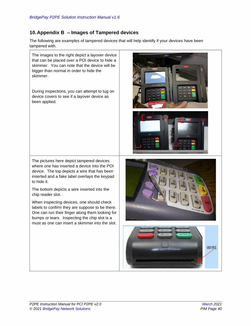
10. Appendix B – Images of Tampered devices
The following are examples of tampered devices that will help identify if your devices have been
tampered with.
The images to the right depict a layover device
that can be placed over a POI device to hide a
skimmer. You can note that the device will be
bigger than normal in order to hide the
skimmer.
During inspections, you can attempt to tug on
device covers to see if a layover device as
been applied.
The pictures here depict tampered devices
where one has inserted a device into the POI
device. The top depicts a wire that has been
inserted and a fake label overlays the keypad
to hide it.
The bottom depicts a wire inserted into the
chip reader slot.
When inspecting devices, one should check
labels to confirm they are suppose to be there.
One can run their finger along them looking for
bumps or tears. Inspecting the chip slot is a
must as one can insert a skimmer into the slot.

BridgePay P2PE Solution Instruction Manual v1.6
P2PE Instruction Manual for PCI P2PE v2.0 March 2021
© 2021 BridgePay Network Solutions PIM Page 41
The device to the right has been tampered
with and had the back removed and a skimmer
inserted. Always check the back of devices to
look for tampering. Attacker will remove the
back of devices and insert devices. Check of
strange labels and check all screws to ensure
none are removed. Around screw locations,
check for scratches to see if someone may
have opened the device.
This is another example of a sticker hiding
damage to a device. Always closely inspect
stickers and labels to see if they have been
removed. Run finger across the sticker to see
if there are holes behind them.
Always check all security seals for wear and
tear and tampering. Seals that look pulled
back are an indication of tampering.
These are just some examples of devices that have been tampered. Remember you POI device should
only be physically connected to the network or a computer. Review the list of equipment that can be
attached to a device and confirm that those are the only things connected. Strange device or wires
BridgePay P2PE Solution Instruction Manual v1.6
P2PE Instruction Manual for PCI P2PE v2.0 March 2021
© 2021 BridgePay Network Solutions PIM Page 42
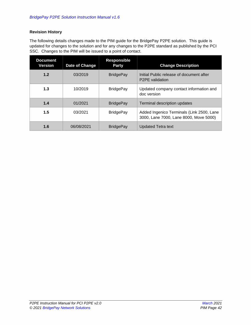
Revision History
The following details changes made to the PIM guide for the BridgePay P2PE solution. This guide is
updated for changes to the solution and for any changes to the P2PE standard as published by the PCI
SSC. Changes to the PIM will be issued to a point of contact.
Document
Version Date of Change
Responsible
Party Change Description
1.2 03/2019 BridgePay Initial Public release of document after
P2PE validation
1.3 10/2019 BridgePay Updated company contact information and
doc version
1.4 01/2021 BridgePay Terminal description updates
1.5 03/2021 BridgePay Added Ingenico Terminals (Link 2500, Lane
3000, Lane 7000, Lane 8000, Move 5000)
1.6 06/08/2021 BridgePay Updated Tetra text