Breech Design
251
U 1 G~RCOM PAMPHLET AIM-47625 CID 7 ENGINEERING ESIGN L0 S.HANDBOOK. BREECH MECHANISM DESIGN DDC TAB Ulksamounced 2 Justification I__t.:,,-i y • ,"• Code.s' EDJ st speclal1 I I~ Aail a/or ; S ARMY MATERIEL DEVELOPMENT AND READINESS COMMAND .FEB. 9
-
Upload
nikhil-zope -
Category
Documents
-
view
334 -
download
47
Transcript of Breech Design
U1G~RCOM PAMPHLET AIM-47625
CID
7 ENGINEERING ESIGNL0
S.HANDBOOK.
BREECH MECHANISM DESIGN
DDC TABUlksamounced 2Justification
I__t.:,,-i y • ,"• Code.s'
EDJ st speclal1I I~ Aail a/or ;
S ARMY MATERIEL DEVELOPMENT AND READINESS COMMAND .FEB. 9

r-UNITEM S TMENT OF CI•;4rIE IC•' I'ntional Terchnical Information Service
,•..L.-• 5795 Port Royal Road* Springield. Virgtiva
Date.' N NTS Control I S
TO: Cefen eDoc•.een'tation 'Center - DDC/TCC•neron Stati.nAlexandria, Virginia 22314
FRO.: NTIS, Input Braftch
5285 Port Royal RoadSpringfield, Virginia 22161 - M A 0 7 9 6 6
Reriort. 7"r 2 COM d op4ap P D
Title: A ~Sujec report is /-7" Standard Process t STC report. SIC SpecialT
Subject reporcisl Te 0olg-
Group. [7 ctute-r Product. - Follow up date.. I
/ The report will be accessioned by DDC. The form noting the ADA number isreturned.
-- The report has been assigned the ADA number noted above and is returned toNTIS for processing.
/7 DDC will not process ;he repor-t. It is returned to NTIS.
Hag Tape Price ______
PC & I-IF Pricejj-T s Source-4 Z i L , z .Stock quantity IrSource Share__________
Comments: , "
Signature Cfor billing)
Copy when completed to .1Fiiiancc Branch.
DOD Report Action Requl~st &1(Replaces NTIS-164 5-72)
* . A~~1. ', -. *•,
•A.. . . , ,. .. .4, , . 4,•" . . 4. . .. . .4
* . ..... .... ' " " ' 4." --. ' .r
. . . .. " ", .i " .• . , .,.,• :I < ":':
:"."o;.'. X.:" " , ' • . ' , -; .I" ' . ; '" ' - , . .i . . ' :./ .. '"''• -.F ••,.=- : :.' ' : • ., . .; ., •-'," ...- , '.. '.' .• " .. - . .; .t>' -.-- - t" , ,l':,•:.' .,.' ... ,7 ..A .'• .. •*• '
q .... . .. . ..
ft 2#RCOM-P 708-253
DEPARTMENT OF THE ARMYHEADQUARTERS US ARMY MATERIEL DEVELOPMENT AND READINESS COMMAND
5001 Eisenhower Avenue, Alexandria, VA 22333
FiDARCOM PAMPHLET February 1919No. 706-253 tiV* ENGINEERING DESIGN HANDBOOK
L BREECH MECHANISM DESIGNTABLE OF CONTENTS
Paragraph Page.LISTOF ILLUSTRATiONS ....................................... viiLISI'OFTABLES................................................ xPREFACE ...................................................... xi
CHAPTER 1. INTRODUCTION
SECTION 1. GENERAL CONSIDERATIONS1-1 Handbook Scope....... ......................................... . -11-2 Terminology With 'Resvect o~ Caliber................ ...... ........... 1-2
i -2.ý Breech Mechanism Definition..................................... 1-2 [1-2.' Breech Mechanism Functions ....................... .............. 1-2
1-3 Typical Operational Cycik. ............... .......................... !-3
SECTIION 11. BREECH MECHANISIM TYPES1-4 Application Considerations ......................................... 1-41-4.2 Sl-Propeled Weapons ............................................. 1-71-4.2 TefPow eled We~apons... ........................................... 1-41-4.3 Ammunition D~ictates........................................... 1-101-44 Raie of Fire........................................ ............ 1-111-5 Types of Closure .................... ............................. 1-1 11-5.1 Interrupted Screw ..................................... .......... 1-12
1-52 Sliding Wedge........................ ...................... ... 1-14I1-5.3 Sr~parahle Chamber ............. ................................ 1-171-5.4 Eccentric Screw ..................................... ........... 1-221-5.5 Developmental and Experim-ental Closure Concepts..................... 1-24
*1-6 Mechaniskea and Component Breakdown ............................... 1-24* 1-6.1 Breech Structtsre/Closure ..................... ...... ............. 1-25
1 -6.2 Operating Mechanism ......................... .................. 1-271 -6.3 Firing Mechanism ............. ........ ...... .................. 1-27-633 3eusinfrSartLaigAr.nto............1.:1-6.3.1 Electric and Electric- Perc ussion Firing Mlocha~iism....................1-28
1-6.3.2 Percusmion for Cased Ammunition .. . . . . . . . . . . . . . . . . . . ........ 1-291-6.3.3_ __ __ __ __ _ Pec sinfrS p rt-Lo dn m u iin . . . .. . . . . . . . - .) ~ -6.4 Safety !nterlocks ............. ..................... ............. 1-32
DARCOM-P 706-!!k
TABLE OF CONTENTS (%;ont'd)
Paragraph Page
1-6.5 Extracting Mechanism ............................ ............... 1-321-6.6 Obturating Mechanism .......................................... 1-33 [
SECTION 111. DESIGN RESPONSIBILITY
1-7 Interfaces With Other Subsystems .................................... 1-341-7.1 General ....................................................... 1-34a1 -7.2 Ammunition ................................................... 1-351-8 Design Procedure.................................................. 1-351.8.1 Desiimn Layout.................................................. 1-361-8.2 Design Analysis................................................. 1-361 -8.3 Material Selection............................................... 1-371-8.4 Engineering Drawings............................................ 1-371-8.5' Summary...................................................... 1-37
References....................................................... 1-38
CHAPTER 2. DESIGN CONSTRAINTS
SECTION 1. OVERVIEW....................... 2-1
SECTION 11. AMMUNITION INFLUENCE2-1 Fixed Ammunition................................................ 2-4Ma2-2 Semnifixed Ammunition............................................. 2-42-3 Separate- Loading Ammunition ...................................... 2-42-4 Consumable Case Round ........................................... 2-92-5 Rocket-Type Rounds .............................................. 2-11
SECTION 111. WEAPON INTERFACES
2-6 Tube and Chamber................................................ 2-1 12-7 Bore Evacuation and Scavenger Systems................................ 2-14J 2-8 Recoil System .................................................... 2-142-9 Mounts....................... .................................. 2-162-10 Fire Control ..................................................... 2-172-10.1 Fire Control Equipment.......................... I................ 2-172-10.2 Dimensional Relationships between Weapon Components and Fire Control
Compensation Devices ......................................... 2-18
SECTION IV. BREECH AND SUBASSEMBLIES DESIGN EXAMPLES2-11 Operating Mechanisms............................................. 2-202-j11. i Horizontal Sliding Wedge............ ............................. 2-202-11.2 Vertical Sliding Wedge ........................................... 2-262-11.3 Interrupted Screw............................................... 2-312-12 Firing Mechanisms................................................ 2-372-12.1 Continuous-Pull Percussion, M 13..................237f" p2-12.2 Spring Actuated, Inertia Percussion................................. 2-38 fi
DARCOM-P 706-253
TABLE OF CONTENTS (cont'd)
Paragraphi Page
2-12.1 Percussion Hammer ............................................. 2-432-12.4 Cont inuous- Pull Percussion, In-Line Hammer......................... 2-482-13 Extracting Mechanism ............................................. 2-51L2-14 Obturating Mechanism ............................................ 2-55
SECTION V. FUNCTIONAL REQUIREMENTS2-15 Operating Methods................................................ 2-602-15.1 Manual Operation............................................... 2-602-1 5.2 Semiautomatic Operation ......................................... 2-602-15.2.1 Internal Power................................................ 2-602-15.2.2 External Power ............................................... 2-612-16 Elevating and Traversing Intcrfaces................................... 2-642-17 Operating Simplicity................. I............................. 2-64
SECTION VI. DESIGN REQUIREMENTS
2,18 Rate of Fire ...................................................... 2-65h2-19 Weight ......................................................... 2-652-20 Space Constraints................................................. 2-682-20.1 Turret Guns ................................................... 2-682-20.2 Field Guns..................................................... 2-69
2-20.3 Loading.......................................................2-692-20.4 Ejection...................................................... 2-702-20.5 Recoil............................... ......................... 2-702-21 Dynamic Loading................................................. 2-702-21.1 Pressure ...................................................... 2-702-21.2 Force ......................................................... 2-712-21.3 Tem~perature................................................... 2-71
2-22 Man/Machine Relationships ........................................ 2-74I2-22. 1 Human Engineering ............................................. 2-742-22.2 Operating Effort and Range of Motion ......... ..................... 2-762-23 Safety .......................................................... 2-762-23.1 Safety Program ................................................. 2-782-23.2 Malfunctions................................................... 2-802-24 Climatic Environment .............................................. 2-802-25 Reliability, Availability, Maintainability, and Durability (RAM-D)...........2-802-25.1 Reliability ..................................................... 2-852-25.2 Maintainability................................................. 2-852-26 Producibility..................................................... 2-862-27 Thread Connections............................................... 2-872-28 Material Selection................................................. 2-88
Rd4erences....................................................... 2-96 .Bibliography..................................................... 2-100
iiAl
DANCOM-P 70-263
TABLE OF CONTENTS (cont'd)
ParagrapA Page
CHAPTER 3.DESIGN CRITERIA AND PROCEDURES-INITIATION THROUGH PROTOTYPE
3-0 List of Symbols ................................................... 3-1
SECTION 1. TACTICAL INPUTS TO DESIGN
3-1 Required Operational Capability ........................... ......... 3-33-2 Weapon Application and Mission..................................... 3-33-3 Rate of Fire ...................................................... 3-33-4 Ammunition Requirements........................I............. I.... 3-3
SECTION 11. DESIGN PROCESS3-5 Establishing Feasibility............................................. 3-43-6 Functional Design Layouts .......................................... 3-43-7 Subassembly Layouts; Component Details.............................. 3-43-8 Materials ....................................................... 3-73.9 Breech Mechanism Integration With Weapon System..................... 3-83-10 Interface With Analysis............................................. 3-8
SECTION Ill. DESIGN ANALYSES3-11 Kinematic Analysis................................................ 3-93-12 Kinetic Analysis .................................................. 3.93-13 Stress Analysis .................................................. 3..393-14 Weight Analysis .................................................. 3-10
3-15 Reliability Analysis................................................ 3-103-15.1 Mechanical System Limitations .................................... 3-113-15.2 Standard Prediction Techniques.................................... 3-133-15.3 Probabilistic Design .......... .................................. 3-133-16 Computer Usage ........ ......................................... 3-143-17 Typical Breech Component Illustrative Design Calculations.................3-153-17.1 Kinematic Analysis of Breech Operating Crank ........................ 3-163-17.2 Kinetic Analysis of Breech Operating Crank .......................... 3-203-17.3 Dynamic Analysis for Breech Recoil Parameters ....................... 3-243-17.4 Stress Analysis of Opzn Breech Ring................................. 3-263-17.5 Stress Analysis of Closed Breech Ring................................ 3-303-1 7.6 Stress Analysis of Sliding Block..................................... 3-343-17.7 Stress An~alysis of an Interrupted-Thread Block ........................ 3-363-17.8 Block-Thread Stress Analysis ...................................... 3-403-17.9 Reliability Analysis of Breechblock Crank...................... ...... 3-41
SECTION IV. PROTOTYPE TESTINGA*
3-18 General Considerations............................................. 3-45 d,3-19 M odels . . . . . . . . . . . . . . . . . . . . . . . . . . . . . . 3 43-20 Performance Simulation Tests.............. ......................... 3-46
iv
OARCOM-P 706-253Ail
TABLE OF CONTENTS (cont'd)
Paragraph page
References ...................................................... 3-47Bibliography ..................................................... 3-48
CHAPTER 4.DEVELOPMENT CR~ITERIA AND PROCEDURES
SECTION 1. D)EVELOPMENT EVALUATION PROGRAM4-1 General Consideratiors.............................................. 4-1H4-1.1 Tresting .... .................................... I.............. 4-14-1.2 External Influences ...... ....................................... 4-1
*4-1.3 Simulation Tresting .............................................. 4-2H4-1.4 Engineering Trest/ Expanded Service Test (DT-2) ...................... 4-34-1.2nta Protoyedestign Deficiencies...................................... 4-34-12 nta ProtoyeDection Testiecis ( ......).............................. 4-3J4-2.1 Mechanism Malfunctions ......................................... 4-3 J4-2.2 D~esign D~eficiencies .......................................... ... 4-34-2.3 Maintenance................................................... 4-4
4- D Ievelopmental Redesign Phases.................................... 4-44-4 Acceptance: Engineering/ Service Tests................................ 4-44-4. 1 Proof-Test Procedures .......................... ................. 4-74-4.1.1 Ii ~ore-Fire Checks and Preparation............................... 4-74-4.1.3 AtrProof-Fn Checks an efrac..........................I ........I.....4-74-4.1 .2 AtrProof-Frn Thecsts............ce............................... 4-74-4.2 Climatic Test Firing ............................................. 4-74-4.2.1 Emplacement of Weapon ....................................... 4-74-4.2.2 Firing Schedule ......................... ..................... 4-74-4.2.3 After-Fire Checks and Preparations (Climatic Testing) ................. 4-74-4.3 Acceptance.............. ...................................... 4-84-4.3.1 Proof Markings............................................... 4-84-4.3.2 Acceptance Criteria ................... ........................ 4-8
*4-4.4 Endurance-Life Tests......................................... 4-84-.5 Performance Evaluation ............................................ 4-8
4-5.1 Maintainability ....................... ......................... 4-84-5.2 D~urability ..................................................... 4-1 1
SECTION 11. DESIGN FINALIZATION4-6 Incorporation of Developmental Results ....... ........................ 4-124-7 Organizational Documentation, the Technical Data Package................4-124-7.1 Product Specification ............................................ 4-124-7.2 D~ata List ...................................................... 4-12
4-.3Parts List ........................... .......................... 4-12
4-7.4 D~rawings...................................................... 4-12
v
jo1
DARCOM-P 706-323
TABLE. OF CONTENTS (cont'd)
Paragraph Page
4-7.5 Q uality Assurance Data ........................................... 4-134-7.6 Standards and Specifications ....................................... 4-134-7.7 End Item Final Inspections Requirements (EIFIR) .................... 4-134-7 8 Revision System .................................................. 4-134-8 Operating and Maintenance Manuals ................. -............... 4-134-9 Standardization and Ituterchangeabilizy ................................ 4-14
SECTION IIl. PRODUCTION PLANNING4-10 M anufacturing Engineering .......................................... 4-174-10.2 M ethods . ............................... ...................... 4-174-10 .2 M aterials ....................................................... 4-174-10.3 Econom ics ....................................................... 4-184-11 Military/Industrial Procurement Considerations ...................... 4-224-1 1.1 Planning ........................................................ 4-224-11.2 Tool and Gage Requirements ...................................... 4-22
R eferences ........................................................ 4-27G lossary .......................................................... G -1In d e x . . . . . . . . .. . . . . . . . . . . . . . . . . . . . . . . . . . . .. . . . .. . . . . . . . . . . . . . . . . . . 1-1 "1
II
vi
- .L -
DARCOM-P 706-253
LIST OF ILLUSTRATIONS
Figure .\t. Title Page
"- I Large Caliber W eapon Form s ... .................................... 1-5",-2 Interrupted-Screw Breech Stepped Thread ............................. 1-13--3 Sliding-Wedge Breech Principles .................................... 1-161-4 Vertical Sliding-Wedge Sequence, Showing Breech-Ammunition Interaction 1-18I -5 Separable Chamber Breech--Schematic Sequence of Motions (2 pieces) 1-291-6 Eccentric-Screw Breech ............................................. 1-231-7 Evolution of Interrupted-Screw Threads and Breechblock ................. 1-261-8 Electric Firing Mechanism Schematic for a Consumable Case Round ....... 1-302-I Types of Complete Rounds of Artillery Ammunition ...................... 2-32-2 Artillery Chamber and Ammunition Configurations ...................... 2-72-3 Separate-Loading Propelling Charges .............................. ... 2-82-4 Fiber Felted Consumable Cartridge Cases ............................. 2-102-5 Breech Ring and Tube interface on an Interrupted-.c:'ew Type Breech ...... 2-122-6 Case Chamber Stress-Strain Curves ................................. 2-132-7 Chamber W ith Pertinent Dimensions .................................. 2-152-8 Schematic Diagram of Bore Evacuator Operation ........................ - 2-16 r2-9 Gunner's Quadrant, MI .......................................... 2-182-10 Panoramic Telescope Ml, and Telescope Mount M3 ..................... 2-192-11 Panoramic Telescope M 115, and Telescope Mount M 137 ................ 2-202-12 Elevation Q uadrant, M 15 ............................................ 2-212-13 Concept of the XM39 Electronic Viewing Equipment Installation .......... 2-222-14 Parts of the Operating Mechanism and Other Breechblock Mounte-d Groups
in a Horizontal Sliding-W edge Breech ........ ...................... 2-232-15 Typical Operating Mechanism for a Horizontal Sliding-Wedge Breech
(Sequence of Motions) .......................................... 2-242-16 Operating Lever Parts (Horizontal Sliding-Wedge Breech, 105 mm Howitzer,
N1110) ...................... ......................... ..... ... 2-252-17 Kinematic Sequence Leading to Engagement of Operating Cam by the Breech
Operating Crank-Breech Actuating via Recoil Energy .................. 2-27S 2-18 Typical Operating Mechanism Schematic for Vertical Sliding-Wedge Breech
(Semiautomatic Actuation via Recoil Energy) ......................... 2-292-19 Parts of Semiautomatic Breech Operating Mechanism .................... 2-312-20 Typical Operating Mechanism for Interrupted-Screw Breech .............. 2-322-21 Typical Operating Lever and Crankshaft Group ......................... 2-332-22 Counterbalance Mechanism--Interrupted-Screw Breech .................. 2-342-23 Parts of the Operating Mechanism and Other Breechblock Mounted Group
in an Interrupted-Screw Breech ..................................... 2-362-24 Firing Lock M 13, Operating Sequence .................................. 2-392-25 Spring Actuated, Inertia Percussion Firing Mechanism With Vertical Sliding
W ed ge .......................................................... 2-4 1S2-26 Schematic of a Solenoid Actuated Percussion Firing Mechanism ............ 2-44
2-27 Percussion Hammer Firing Mechanism ............................... 2-45
vii
DARCOM -P 706-253
LIST OF ILLUSTRATIONS (cont'd)
b'191re .Vo. Title Paqg
2.28 Firing Block Assembly Mil (155 mm Howitzer, M1A1) ................... 2-472.29 Percussion Mechanism M35 (175 mm Gun, M I 13A I) ................... 2-492-30 Continuous-',ill Percussion, In-l.ine Hammer Firing Mechanism .......... 2-502-31 Cartridge Citse Extractors ......................................... 2-522-32 Extracting Mechanism Working Sequence fo, i Vertical Sliding-Wedge
K reec h . . . .. . .. . . .. .. .. . .. . .. . . . .... .. .. .. .. . ... . . . . .. .. .. . . ... .. 2-532-33 i eBange Obturating M echanism ..................................... 2-572.34 Expansion Type Obturator, Separable Chamber Breech Application ........ 2-592.35 Externally Powered Breech Interface Function (Hydraulic Loader/Rammer,
175 mm Self-Propelled Gun, MI 1 3AI -M 107 Tracked Vehicle) .......... 2-622-36 Externally Powered Semiautomatic Breech (Separable Chamber Type,
S152 mm Gun/Launcher) .......................................... 2-632-37 Typical Space Constraints in a Turret Gun (Based on M48 Tank) ......... 2-672-38 Elastic Strength Curve Compared to Actual and Permissible Pressures ...... 2.722-39 Typical Recoil Travel Velocity-Pressure Versus Time ................... 2-732-40 Arm, Hand, and Thumb-Finger Strength (Pounds) (5th Percentile Male) 2-772-41 Manual Lifting Capacity: Lifting Forces That Can Be Exerted by 95% of
Personnel, Using Both Hands ....................................... 2-782-42 Procedure for Dealing With Misfire Under Possible Cook-Off Conditions ..... 2-8i2-43 Procedure for Dealing With Misfire of Fixed or Semifixed Ammunition ....... 2.822-44 Procedure for Dealing With Misfire of Separate-LoAding Ammunition ....... 2-832-45 Threads Used to Attach Breech Ring and Tube ........................ 2-892-46 20-deg Pressure Angle Thread Form Dimension Locator Diagram for
T ab le 2-6 ....................................................... 2-9 1"3-I Breechblock Assem bly .............................. ............... 3-53-2 B reechblock ....................................................... 3-63-3 Stress--Strain Diagram in M ild Steel .................................. 3-7
3-4 M ortality C urves ................................................... 3-123-5 Reliability N om ograph .............................................. 3-143-6 Typical Stress-Strength Interaction Diagram .......................... 3-153-7 Breech O perating Linkage ........................................... 3-173-8 Breech Operating Crank Geometry ............ ........................ 3-183-9 Breechblock M otion ....................................... ....... 3-213-10 Forces Acting on Crank .............................................. 3-223-11 Torque Applied to Breechblock Crank ................................. 3-233-12 Recoil Force D iagra n ............................................... 3-253-13 Typical Sliding-Block Breech Rings ................................... 3-273-14 O pen Breech R ing .................................................. 3-283-15 Stress Concentration Factors in Fillets for Tension and Bending ............ 3-313-16 Closed Bk eech Ring .............................................. 3-333-17 Typical Bceechblock Section ........................................ 3-35 ILI3-18 Breech Loading Configuratio ...................................... 3-37
viii
6. L -&I AQ .. WA
/• DARCOM-P 706-2513
tv . LIST OF ILLUSTRATIONS (coirst'd)
'•Fig#, e Ao. Title Pae
3-19 Idealized Breechblock Geometry and Loading Conditions ................. 3-38
3-20 Tthick-Plate G(eometry and Loading Conditions lor Timpo Solution ......... 3-393-2 1 Sector T hread ..................................................... 3-41
3 -22 Safety Factor Related to a Probability of Failure ......................... 3-433-23 Breechblock Crank (Illustrative Geometry) ............................. 3-444-1! Work Flowchart ((First or Contract) .................................. 4-54-2 W ork Flowchart (Subsequent Production) .............................. 4-64-3 Finish Machined Parts, Finish Machining in Final Assembly Approach for
Interchangeability ................................................ 4-154-4 Prior-lDimensioned Parts, Prior-Designed Approach foi Interchangeability ... 4-164-5 Total Cost per Piece---Sum of Tool Costs, Machining Cost, and Nonproductive
Cost ....................................................... 4-204-6 M achining Costs and Surface Finishes ................................. 4-21
- 4-7 Relationship of Tolerance to Cost ..................................... 4-224-8 Q uality Standards Versus Cost ......................... ............. 4-234-9 Depth-Cost Study of Drilled Holes .. ................................. 4-24
4-10 Cost Beha•,ior in Face Milling ...................................... 4-254-1 I (General Pattern. of Grinding Costs ..................................... 4-264-12 M achine and Operator Cost Effect .................................... 4-27
ix
'...
k• -• - -: • 1 '
DANCOM.P 701-M
LIST OF TABLES 3Table .o. Tile Page
I-I Towed Weapon Characteristics as Related to Breech Design ............... 1-61-2 Self-Propelled Weapon Characteristics as Related to Breech Design ......... .- 91-3 Comparative Characteristics-Sliding-Wedge and Interrupted-Screw Breech 1-191.4 Safety Characteristics of Typical Firing Mechanisms ..................... 1-332-1 Amm unition Characteristics ......................................... 2.52.2 Principal Design Requirements of Elastic Obturator Pads ................. 2-562-3 Conventional Control M ovements ..................................... 2-752.4 Range of H um an M otion ............................................ 2-792-5 Effects of Environmental Factors on Breech Materials .................... 2-842-6 20-deg Pressure Angle Thread Dimensions .............................. 2-902.7 List of Specifications for: Cannon, 155 mm, Howitzer, XM 1191 ............. 2-922-8 Protective Finish-Drawing Number Matrix ............................ 2-942-9 Breech M echanism Part M ,trix ....................................... 2-964-1 Firing Schedule .................................................... 4-74-2 Categories of Maintenance in a Theater of Operations .................... 4-104-3 Standard M achining Operations ...................................... 4-184-4 Comparison of Machinability Index Ratings for Selected Alloys ............ 4-19
X 'xi
DARCOM-P 706-253
PREFACE
The Engineering Design Handbook Series of the US Army Materiel Development and ReadinessCommand is a coordinated series of handbooks containing basic information and fundamental datauseful in the design and development of Army materiel and systems. The handbooks are authoritativereference books of practical information and quantitative facts helpful in the design and development"of Army materiel so that it will meet the tactical and the technical needs of the Armed Forces.
This handbook has been prepared as an aid to engineers designing breech mechanisms. Fundamen-tat design information not readily attair.-ble elsewhere is presented along with requirements andproblem areas that are unique to bree(. mechanisms,
The material presented in this handbook is composed of data and design information gathered frommany sources; however, treatment is limited to one of condensation and summary because of the sub-ject scope. References appear -At the end of each chapter for guidance in acquiring additional informa-tion. A glossary has been provided at the end of the handbook.
When reference is made to Military Specifications, regulations, or other official directives, it is doneto reveal the existence of these documents. In this respect, the user should obtain the current editionsfor applications.
This handbook was prepared by liT Research Institute under subcontract to the EngineeringHandbook Office of the Research Triangle Institute, Research Triangle Park, NC, prime contractor tothe US Army Materiel Development and Readiness Command for the Engineering Design Handbook
b Series. Members of the Benet Weapons Laboratory-a US Army Armament and Development Coin-mand organizational element located at Watervliet Arsenal-provided guidance, review of the text
material, and support by furnishing source data and references. Major contributions to the prepara-I! tion of this handbook were made by Mr. Frank Bartos and Mr. Milton Nusbaum, lIT ResearchInstitute.
The US Army 1)ARCOM policy is to release these Engineering Design Handbooks in accordancewith 1)OD Directive 7230.7, 18 September 1973. Procedures for acquiring Handbooks follow:
a. All Department of Army (DA) activities that have a need for Handbooks should submit their re-quest un an official requisition form (DA Form 17, 17 January 1970) directly to:
CommanderLetterkenny Army DepotATTN: SDSLE-AJD
"Chambersburg, PA 17201."Need to know" justification must accompany requests for classified Handbooks. DA activities willnot requisition Handbouks for further free distribution.
b. DOD, Navy, Air Force, Marine Corps, nonmilitary Government agencies, contractors, privateindustry, individuals, and others-who are registered with the Defense Documentation Center (DDC)and have a National Technical Information Service (NTIS) deposit account-may obtain Handbooksfrom:
Defense Documentation CenterCameron Station
* fAlexandria, VA 22314,
xi

DARCOM-P 706-263
c. Requestors, not part of DA nor registered with the DDC, may purchase unclassified Handbooksfrom:
National Technical Information CenterDepartment of CommerceSpringfield, VA 22161.
Comments and suggestions on this Handbook are welcome and should be directed to:US Army Materiel Development and Readiness Command5001 Eisenhower AvenueAlexandria, VA 22304.
DA Form 2028, Recommended Changes to Publications, which is available through normal publica-tion supply channels, may be used for comments/suggestions.
- ---
DARCOM-P 700-263
|e' Ml e V ie e- I A1ic .et Prorcs L 4 "3
-~ -CHAPTER 1 oi. od o 4hrou
INTRODUCTION - l u Wl, a,.d
SECTION I. GENERAL CONSIDERATIONS& Pd u'j.ý -
1-1 HANDBOOK SCOPE Subject content and scope of the handbook
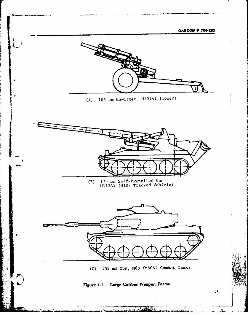
This handbook is devoted to a description of a deserve a degree of definition as earl, as possible.rational design sequence and methodology Specifically, the handbook contents are limited toneeded to take a particular breech mechanism breech mechanisms of crew-served, "largefrom conception-as prompted by military needs caliber", land based guns and howitzers, in-and technical requirements generated for a given cluding self-propelled weapons and tank guns.weapon-to the stage of acceptance and produc- The treatment is oriented toward designtion. Major divisions of the handbook provide ip- guidance, design examples, and engineering dataformation and guidance on the various design in- as practical. Breech mechanism design for mor-terrelationships involved. ........ .. tar, recoilless, and other weapon types has been
The designer should keep in mind that the sole left for coverage in subsequent handbooks.purpose of a weapon system is to provide the fire- The meaning of "large caliber" weapon haspower needed to meet the system requirements. different connotations among the various hand-
SThe breech mechanism is one of several key sub- book users. Because it is a less than rigorouslyassemblies in the cannon subsystem which in defined term and undoubtedly no single defini-
', '" turn is one of several that make up the total tion will enjoy full consensus, further discussion
weapon system. One particularly important of "large caliber" is provided in par. 1-2. On thefunction which this handbook serves is to assist basis of Army weapons previously or presently inengineers, without prior breech mechanism existence, an overall range from 37 mm to 280design experience, in the design of this signifi- mm bore diameter can be offered for readercant cannon subassembly. Normally, the design guidance; but the upper limit of caliber easily ex-may be best achieved by a team of engineers tends to 16 in. bore, if seacoast or railroad ar-comprised of a group of multidisciplinary tillery is included.specialists, each with competence in a specific However, in the context of this handbook,area related to the breech mechanism. These emphasis is justifiably placed on more currentareas include: 'onfiguration innovation; design weapon applications and first-line equipment -analysis (kinematic, kinetic, stress, weight, and having a caliber range of about 105 mm to 8 in.reliability); material selection; maintenance; (203.2 mam). Of course, weapons within theproduction; and cost. This group should also in- broader size range are also covered wherever theyclude an experienced technical manager to provide information significant to breech design.assure that each member has equal stature and Weapons no longer in use and ones having futureresponsibility, and that their particular exper- potential comprise such inputs.tise is applied consistently. The design team has The subject of breech mechanism design en-a responsibility which starts with the breech tails a large number of topics; accordingly, de-mechanism concept and continues throughout tailed, comprehensive coverage in one convenientthe service life of the weapon system. Section III volume is an impossibility. Therefore a general-
" of this chapter describes design responsibility ized approach is used, as suitable, in order toand the team approach more fully. make the discussions applicable to a number of
i- . S. itijh. . . .. j, skL- -. &.," • ' -
DARCOM-P 706-53
similar cases. Users of this handbook should not The various elements of the breech system are • /expect to find complete, step-by-step procedures individually treated at appropriate points of theon every conceivable breech design problem or handbook. A glossary of technical and ordnanceapplications they might encounter (e.g., antiair- terms used in the handbook and requiringcraft or antitank artillery, per se). The assumption separate definition appears at the end of theis made that the handbook users are competent volume.to modify the given procedures to make them ap- I'
plicable to specific cases. 12.1 BREECH MECHANISMDEFINITION
The handbook glossary provides terminology1-2 TERMINOLOGY WITH RESPECT TO definitions for the important components and
CALIBER mechanisms whirh comprise a breechThe approach is taken in this handbook to mechanism. Webster's Third New International A
arrive at the designation "large caliber" Dictionary provides the following definitions-weapon-and more particularly to its lower and 1. Breech. The part of a cannon or otherupper bounds. Refs. 1 to 3 are in general agree- firearm at the rear of the bore.ment that a bore diameter larger than 30 mm 2. Breechblock. The block in breech-loading(1.181 in.) constitutes a "large caliber" weapon; firearms that closes the rear of the bore againstthis sire limit is also given in the basic definition the force of the charge.of both "gun" and "howitzer". The lower bound 3. Breech mechanism. The mechanism forof weapon size under consideration here is opening and closing the breech of a breech-further related to the administratively set max- loading firearm, especially of a heavw-caliberimum bore of 40 mm for small arms (Ref. 2), gun.
The upper bound of "large caliber" weapon The purpose of the handbook may be bettersize is difficult to set. Certainly, historic evidence served by the definition that follows. The totalityshows the existence of extremely large bore of dev;ces and components: for closing the rearweapons in former times. In World War I, Euro- end of a gun after loading (likewise for con-pean armies commonly employed railway ar- venient access after firing); for firing the round oftillery and siege guns of fantastic calibers. Even ammunition that has been inserted; for contain-as late as World War II, operational use of an ing and sealing the tremendous pressure800 mm (31.5 in.) railway gun can be cited (Ref. developed; and for removing any ammunition4). The foregoing examples, however, are ex- components not projected---all comprise theI•
treme and special cases. Even though such breech me hanism.weapons show virtually no theoretical size limit, The forward and rear ends of a weapon arethey are of little significance toward realistic referred to commonly as "muzzle end" andbreech mechanism design. "breech end", respectively. The muzzle is the
"On the other hand, practical design limits are end of the gun tube from which the projectile
numerous as well as stringent Today, the multi- emerges and the breecb end is that into whichple constraints of mobility, maintainability, and the round of ammunition is inserted.reliability-coul led with drastically differenttactical concepts and specific weapon missions- 1-2.2 BREECH MECHANISMimpose the realistic upper bound on weapon size. FUNCTIONSA practical size limit of 8 in. (203 mm) is not The two basic functions of a large caliberlikely to be exceeded by military requirements of weapon breech mechanism are diametrically op-the foreseeable future. posed. The mechanism must, on the one hand,
S1-2
DARCOM-P 706-253
4 open and be accessible for conveniently receiving has been associated with weapon sizce to 120 mmeach new round of ammunition - also for ex- bore fc:" reasons elaborated in Chapter 1, Sectiontracting any remnants of the previous firing. Oil II. Similarly, larger caliber weapons (approxi-the other hand, it must be able to clooe rapidly mately 155 mm and over) have traditionally usedand at the same time provide adequate structural the rotary (screw block) type of closure-whereintegrity to contain the high propellant pre-sures the block i3 first unlocked by a limited rotationdeveloped in the weapon chamber. then swung out of the breech recess.
These primary functions are part of a definite The firing function occurs with the initiation ofsequence in which the breech mechanism elc- the primer, after the ' -eech has been closed andments operate. The operational cycle consists of locked. Firing mechanisms operate on the princi-a number of actions occuriring in succession, pie of percussion or electrical activation, or awhich must be accomplished simply and eco- combination of the two. During firing, an obtura-nomically, yet with a high degree of reliability. tion step comes into play, in which the chamberFunctional sequence is similar for the weapons is sealed against escape of the propellant gases.under consideration here, however, some varia- The device for prohibiting the loss o" gases can betions do exist. either a part of the breech or a part of the am-
The functions of the breech mechanism are munition. In smaller caliber weaponsperformed by six major subassemblies and a traditioaally associated with metal cased am-safety provision: munition, the case itself performs the sealing
1. Breech ring function; no separate obturating device 'is re-2. Breechblock quired in the breech. Larger caliber weapons3. Operating mechanism have traditionally used separate loading rounds,4. Firing mechanism which have no cartridge case; therefore, such5. Obturating mechanism breeches require an obturating mechanism.6. Extracting mechanism (Relations between weapon size and ammuni-7. Safety interlocks. tion type are treated later.)
After firing, there is a recoil-counterrecoil ac-1-3 TYPICAL OPERATIONAL CYCLE tion in which momentum is exchanged between
Assume that the breech is empty and the the stationary and moving parts of the weapon.
breechblock has been opened; an operating cy- This is a potential source of energy for actuatingcle then can be conveniently described begin- the breech and is used in a number of largening with the ammunition loading function. For caliber weapon applications. For guns workingsmaller weapons, ammunition is inserted into the in enclosed fighting spaces (tanks, self-propelledbreech by hand; but as weapon caliber becomes weapons), a scavenger device or a bore evacuatorlarger, assist devices are generally necessary. usually is employed to purge the chamber of
The breech is closed behind a new round by propellant residue or noxious fumes - betweenthe breechblock. The method of closing varies ac- successive shots. However, evacuators can onlycording to breech and ammunition type, weapon be used if the breech is opened automaticallyapplication, etc., as detailed later. However, during the last part of the counterrecoil. Thisoperating mechanisms produce rotary, pivot, particular problem regarding personnel protec-slide, or hinge motions in the block. In smaller tion rarely exists in guns that are not enclosed.caliber weapons the breechblock moves at right In manually operated weapons, at this pointangles to the chamber axis to cover or uncover the breech can be unlocked and opened to permitthe chamber opening. This kind of breech, an extraction function to end the operating cycle.broadly termed the slide block type, generally This step removes spent ammunition parts left irt
1-3
' A",4 - --... "-', •"q': ,, ,
:l i , , . . . "" , ,
.1
DARCOM-P 706-253
the breech. For cased ammunition, extraction of loading ammun.ition. Thus, the complexity of the
a full size cartridge case is involved; but only a extractor device varies approximately with case
small primer case has to be extracted for separate size.
SECTION II. BREECH MECHANISM TYPES 1
1-4 APPLICATION CONSIDERATIONS closely accompany or support troops, and ability H
The breech mechanism comprises an un- to provide good firing rates with simple breech
questionably vital subsystem of the overall mechanisms are among the positive attributes of
weapon, but nevertheless it is a subgroup of that this weapon category. Technical developmentslarger end item. Thus, breech mechanism are also well utilized in towed weapons; availa-
classification must include consideration of the bility of newer materials with better physical
total weapon characteristics and the intended properties coupled with optimum design appli-mission(s) of the weapon. Important application cations has resulted in weight reductions withoutfactors of the over~all weapon which bear on sacrifice in performance. One very significant ex-
breech mechanism design are: ample of lighter weight weapon design is the 1051. Type of ammunition to be fired mm Howitzer, M102 (see Table 1-1) which now
sform taken by the weapon; i.e., makes helicopter transportability a routine oper-2. Grossfomtknb th wepnie.
towed weapon, self-propelled weapon, or tank ation. Designs that can provide the additional
(see Fig. 1-1). feature of "air mobility" further reduce theAmmunition type exerts great influence on traditior:al disadvantage associated with towed
breech design. Obviously, the diversity in weapons, A
weapon applications-antiaircraft, antitank, and Simpler,, more self-contained breechtank guns for direct-fire missions; howitzers and mechanisms are required for towed weapons as
maximum range guns for indirect-fire support- compared with self-propelled types; this consid-
requires the use of several kinds of ammunition. eration extends to other subsystems of theIn turn, a particular ammunition type is related weapon as well. The degree of breech mechanism
to the rate of fire, leading task, crew size, and ex- sophistication possible is set by many factors, but
tent of automation required in the breech in towed weapons the lack of external power im-mechanism. As full recognition of ammunition poses one definite limit. (Existence of auxiliary
influences on breech design, pars. 1-4.3, 1-7.2, propelled field pieces is recognized--e.g., the 155
and Chapter 2, Section I, are devoted to detailed mm Howitzer, M123Al-however, such powercoverage of pertinent ammunition-breech rela- sources have limited capability even for motive
tionships. power and are impractical for breech assistance.)Therefore the breech designer must employ in-ternal power sources as practicable (par. 2-15.2.1)and su-istantial design ingenuity to achieve auto-
1-4.1 TOWED WEAPONS mation of certain breech functions.
Despite the many advances of materiel mod- Normally, breech operations are accom-ernization, towed weapons have retained a plished manually. This is quite acceptable up todefinite place within Army requirements. Even the weapon calibers where ammunition type,without motive power of their own, they can physical package, and handling requirements are
-. __*" provide offsetting qualities which maintain their such that competitive weapon performance is £ ',
useful role. Versatility in employment ability, to achieved. For towed weapons it is an acceptably
1-4
DARCOM -P 706-253
(A) 105 mmn Howitzer, MIOlAI (Towed)
(B) 175 mm Self-Propelled Gun,1Mll3AI. (14107 Tracked Vehicle)
(C) 105 mm Gun, M68 (M6OAl Combat Tank)
Figure 1-1. Large Caliber Weapon Forms ¶i
1-5
DARCOM-P 706-253
Pot%
f -r
- !s E ~6I ______ 2.;.2. K s4.- _
jaqwvli+
-ournue -- M
3Upi r
-aft 7 4A V
f Japl---u~
UO!II41-1+ +
u! Itwtu7Cl
E -a
S1IU1~ N~UfI~ lIO~d AI1VN~SUdm
ad-j
1-6v~w
DARCOM-P 706-263
large, proficient gun crew, and lesser space con- feasibility has been shown. Although none ofstraints that make the pe,-ormance possible. In these ronrcep t s meets all military requirements orthe upper caliber range of weapons, e.g., above rigors of that environment, some are promising155 mm bore, th'e physical size of ammunition and offer noteworthy examples for the designer'sand inherent weapon functions hold down the awareness (Refs. 5 to 8).
rate of fire without the presence of power assists. Breech system oriented engineering data andIt is in this area where innovative uses of internal related characteristics of both current and pre-
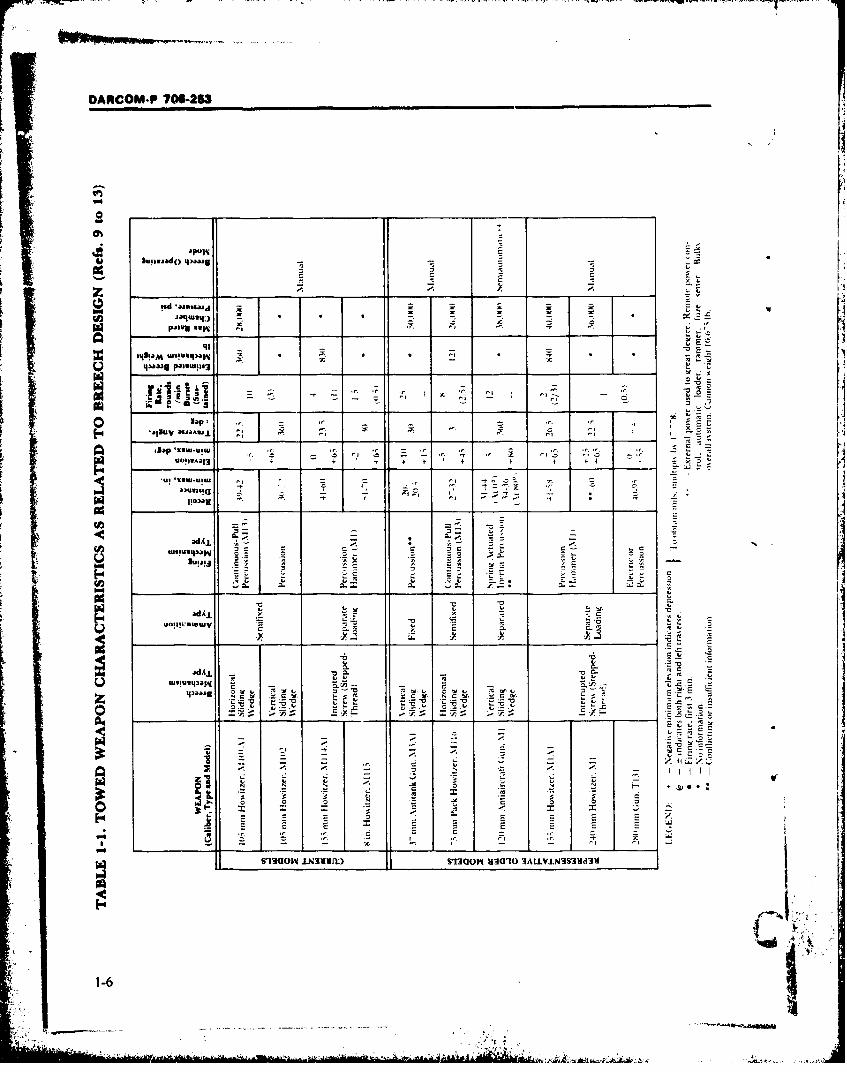
power to automate breech functions are most viously used weapons represent design state ofdesirable and also the most difficult to achieve, the art in one form. Table 1-1, offered for
The preceding is not to say that breech guidance of the designer, is a compilation of per-mechanism automation has not been achieved at tinent data on representative towed weapons
all in towed weapons. Indeed, several weapons from Refs. 9 to 13.have used recoil system energy to obtain semiau-tomatic breech operation, wherein several func-tions are removed from the hand operation mode. 14.2 SELF-PROPELLED WEAPONS
Recoil energy is the most commonly used inter- In the context of this handbook, all weapons ofnal power source and the sliding wedge type an applicable caliber permanently mounted on abreech is especiall well suited for actuation by mobile platform-including self-propelled guns,the readily available linear motion of a gun in howitzers, and tank guns-comprise the self-recoil (see pars. 1-5.2*aid 2-15.2.1). Probably the propelled weapon category. At the same' time,best example of recoilenergy utilization in a the distinctly different missions of the varioustowed weapon is the 75 mm Antiaircraft Gun, total weapon systems involved cannot be
") T83E1. overlooked. Self-propelled guns and howitzersTowed weapons, par:icularly howitzers, im- retain the basic mission of artillery. They provide
pose additional limits on recoil energy utiliza- accurate, indirect supporting fire at medium totion, in firing variable charge ammunition (pars. long range and offer the advantage of full1-4.3 and 2-2). Inherent to the weapon structure, mobility under their own power. These weaponsa long recoil stroke is necessary to contain the are not normally used in direct confrontationlargest charge used. Consequently, at a low zone with the enemy, therefore structural and armorfire mission, the recoil stroke is much shorter protection incorporated around a cannon variesthus making it difficult to provide for breech ac- greatly from model to model, but is much lesstuation. Also, high elevation fire in the lower than found on tanks. In contrast, tanks mainlyzones, provides low counterrecoil force for provide direct fire coupled with the greatestoperating the breech. The magnitude of this force degree of mobility possible. They are essentiallyis a special problem in lighter weight weapons. assault weapons, able to close with the enemy,Further consideration of this design problem is yet fully enclosed and heavily armored to with-given in par. 1-6.2. stand counterfire.
Nevertheless, recent attempts to develop a Several factors which have bearing on breechrapid-fire towed artillery weapon have taken design stem from characteristics of the overallplace in the 105 mm howitzer category and in- weapon system. Presence of a vehicle power plantclude interesting concepts of recoil energy usage. makes external power more readily available for
Single and multiple, revolving or indexing cham- breech actuation. To be sure, this is far from theber breeches; loader-rammer mechanisms; only criterion for deciding to use external power.
* rotary magazines; and their combinations are Rather, the interplay between various con-some breech automation techniques for which straints of a given weapon system set the extent of
1-7
DARCOM-P 706-263nI
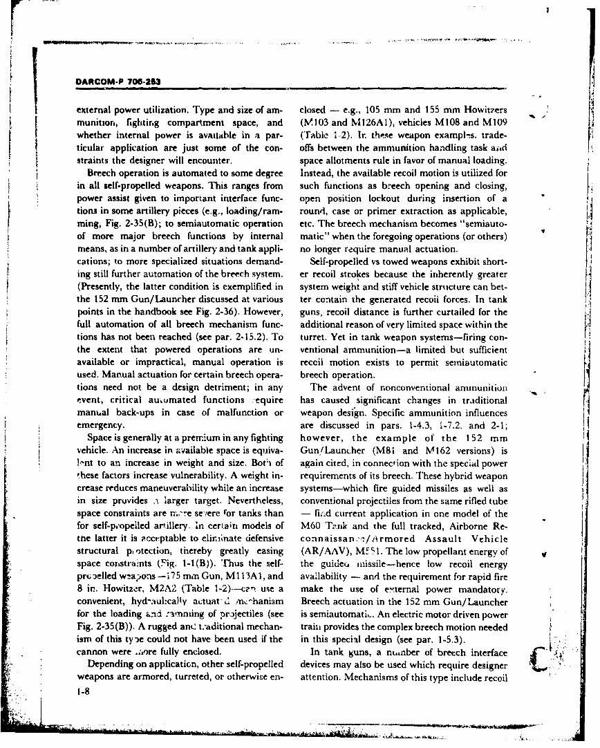
external power utilization. Type and size of am- closed - e.g., 105 mm and 155 mm Howitzersmunition, fighting compartment space, and (M,103 and M126A1), vehicles M108 and M109whether internal power is avaitable in a par- (Table 1 2). Ir. these weapon exampls, trade-
ticular application are just some of the con- offs between the ammunition handling task atidstraints the designer will encounter. space allotments rule in favor of manual loading.
Breech operation is automated to some degree Instead, the available recoil motion is utilized forin all self-propelled weapons. This ranges from such functions as breech opening and closing,power assist given to important interface func- open position lockout during insertion of ations in some artillery pieces (e.g., loading/ram- round, case or primer extraction as applicable,ming, Fig. 2-35(B); to semiautomatic operation etc. The breech mechanism becomes "semiauto-of more major breech functions by internal matic" when the foregoing operations (or others)means, as in a number of artillery and tank appli- no longer require manual actuation.cations; to more specialized situations demand- Self-propelled vs towed weapons exhibit short-ing still further automation of the breech system. er recoil strokes because the inherently greater
(Presently, the latter condition is exemplified in system weight and stiff vehicle structure can bet-the 152 mm Gun/Launcher discussed at various ter contain the generated recoii forces. In tankpoints in the handbook see Fig. 2-36). However, guns, recoil distance is further curtailed for the 4full automation of all breech mechanism func- additional reason of very limited space within thetions has not been reached (see par. 2-15.2). To turret. Yet in tank weapon systems-firing con-the extent that powered operations are un- ventional ammunition-a limited but sufficientavailable or impractical, manual operation is reccil motion exists to permit semiautomaticused. Manual actuation for certain breech opera- breech operation.tions need not be a design detriment; in any The advent of nonconventional ammunitionevent, critical auumated functions .equire has caused significant changes in traditionalmanual back-ups in case of malfunction or weapon desi'gn. Specific ammunition influencesemergency. are discussed in pars. 1-4.3, 1-7.2. and 2-1;
Space is generally at aprerriumin any fighting however, the example of the 152 mmvehicle. An increase in availabie space is equiva- Gun/Launcher (M8i and M162 versions) isV knt to an increase in weight and size. Bot~i of again cited, in connection with the special powerthese factors increase vulnerability. A weight in- requirements of its breech. These hybrid weaponcrease reduces maneuverability while an increase systems-which fire guided missiles as well asin size provides i larger target. Nevertheless, conventional projectiles from the same rifled tubespace constraints are rr-,,re seiere for tanks than - fi:ld current application in one model of thefor self-popeiled artillery. In certain models of M60 Tank and the full tracked, Airborne Re-tne latter it is -cceptable to elii;nate defensive connaissan':/i/rmored Assault Vehiclestructural piotection, thereby greatly easing (AR/AAV), ME, 1. The low propellant energy of vspace coristraIints (Fig. 1-1(B)). Thus the self- the guideu missile-hence low recoil energypr(; jelled w!aonas -175 mm Gun, MI 13A1, and availability - and the requirement for rapid fire8 in. Howitzer, M2A2 (Table 1-2).--cen use a make the use of e'ternal power mandatory.convenient, hydatulhcally actuat d ,n,:hanism Breech actuation in the 152 mm Gun/Launcherfor the loading ,nd r-anming of projectiles (see is semiautomati,. An electric motor driven power
. Fig. 2-35(B)). A rugged anc t:aditional mechan- traiti provides the complex breech motion needed Lism of this tyn)e could not have been used if the in this special design (see par. 1-5.3).cannon were .;,ore fully enclosed. In tank guns, a nuinber of breech interface
Depending on application, other self-propelled devices may also be used which require designerweapons are armored, turreted, or otherwise en- attention. Mechanisms of this type include recoil
"1-8
DARCOM-P 706-263
I .- C c
+sa '4MIm~
uwsqS~~~.T -. 9. r
adAL-WMw~a K - --
414
I- Z4 r -
550 r-r
--pE6 E'4 d a.
inuy',Es
*~~ EUJ~rA E 0 5
-k ;D !s-C
9-3,U -N1I)MO In AIVN~
DARCOM-P 706453
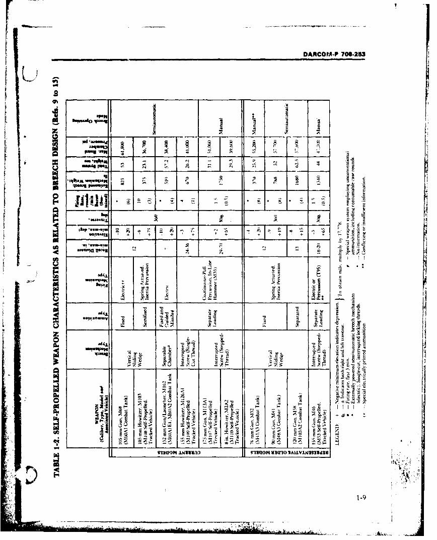
guards, loading trays, and case ejection chutes or projectile and the propeliir.g charge that is con-deflectors. These devices facilitate the breech tained in a sealed case complete with primer.operational cycle, ease ammunition handling The two items may be leaded into the breechtasks, or otherwise assist the gun crew working in separately by hand; in an automated mode, thetight fighting spaces. A chart of engineering data projectiLe and case are set into a loading trayasso i;,ted with breech systems of representative "separately", but breech loading is normally per-self-propelled weapoas is presented in Table 1-2. formed in one operation. This type of round is
used when physical size becomes too large oi irn-1-4.3 AMMUNITION DICTATES practical to handle in the fixed ammunition form.
Effective delivery of firepower upon designated 4. Separate-loading ammunition. A completehostile targets is the sole, ultimate function of a round made up of three distinct components,weapon. Thus, the type (or types) of ammunition wherein no cartridge case is used. Instead, theto be handled and projected by a given weapon is projectile and cloth bag encased propellanta strong dictate on the type of breech needed. In. charge(s) are handled separately and loaded intodeed, reference to ammunition influences is un- the breech. In addition, a primer cartridge is in-,voidable even in the most elemental discussion serted separately into the firing mechanism.of breech mechanism design, as contents of the The order in which the ammunition types areforegoing paragraphs reveali listed corresponds in a general way to increasing
Ammunition for large caliber weapons has alliber; e.g., fixed ammunition is generallybeen variously categorized. For the purposes of associatec1 with the smaller caliber range ofthis handbook, general characteristics and exter- weapons considered here, while the separatenal properties of ammunition type are the impor- loading category implies the larger caliber range.tant considerations. Size, weight, kind of physical (It should be noted that in foreign ordnance, con-package, and number of component parts com- ventional fixed ammunition exists in much largerprising a complete round are obvious character- calibers than in US Army usage.) Further type/istics to be borne in mind. Classification on the size generalization is problematic--especially inbasis of fixed, semifixed, separated, and separate- the semifixed and separated ammunition clas-loading ammunition types is the most widely ses-since complicating overlaps occur due toused approach (Refs. 14 to 16): particular weapon application, tactical consider-
I. Fixed ammunition. A complete round with ations, or design peculiarity.primer and propellant contained in a cartridge Even traditional concepts concerning relativecase permanently attached to a projectile. It is size of "cased" and "caseless" ammunition areloaded into the breech as a unit; caliber size is changing (types 1, 2, 3 vs type 4). For example,limited by weight, package size, and other hand- development of the consumable case helps makeling considerations. the fixed round practicable at much larger
2. Semifixed ammunition. A complete round calibers than hitherto possible. Developmental vin which the cartridge case is not permanently trends are not in one direction only since interestfixed to the projectile so that the incremental also exists in adapting separate-loading ammu-charge within the case can be adjusted to obtain nition to smaller calibers. At least one example ofthe desired range (or zone) of fire. However, it is an operational weapon system using baggedloaded into the breech as a unit and, therefore, charges at 120 mm bore size can be cited in asubject to similar caliber size limits as the fixed British tank application (Ref. 17; sec also pars. 1-round. 5.2 and 1-6.6).
3. Separated ammunition. A complete round Ammunition type has definite implications on "composed of two component parts; namely, the the type of breech mechanism to be used1 the
1-10

P DARCOM-P 706-253
$ newer, unconventional rounds just mentioned breech operations and to assist in ammunitionare important situations in point. In par. 1-5 loading in order to reduce the effort required ofrelations between amzmunit~on type and breech the gun crew. Thus the weapon system firing rateclosure type are established. The various ammu. gives rise to interfaces for the breech designer.nition types also receive more detailed treatment The design features relative to the gun crew es-in par. 1-7.2 ard Chapter 2, Section 11, relat,-'e to tablish human engineering requirements. Inter-their individual influences on breecih design. nal powva' used for semiautomatic operation es-Basic categorization 3f ammunition ins terms of thiaher: in inte,face with the recoil subsystem.weapon size for representative towed and self. Externm' poweied operation interfaces with the
propelled weapons is given in Tables 1-1 and 1-2. powerplant in self-propelled vehicles. Par. 2-18Physical characteristics of ammunition fired from provides additional material pertaining to rate ofthose weapons are further developed in Table 2- fire, and par. 2-22 deals with human engineering.1. '
1-4.4 RATE OF FIRE 1-3 TYPES OF CLOSURE
The weapon rate of fire, rounds per minute, is Structural features and the types of closure arean important weapon system characteristic. properties that distinguish one kind of brvechRates of fire for the class of weapons treatea in mechanism from another. The differences, ofthis handbook are given in Tables 1-1 and 1-2. course, reach well beyond physical appearance;
The rate of fire to which a given weapon each design offers particular advantages an'd, un-system can be designed depends upon several in- avoidably, some disadvantages. Those designsterrelating factors. Small bore guns up to about that maximize advantage while keeping disad-40 mm, using fixed Ammunition, may achieve vantege to a minimum acquire long lived accept-rates on the order of 100 rounds per minute, per ance.barrel. This rate may be increased by increasing Two diverse, complex requirements are im-the number of chambers associated with each posed on every breech structure, regardless of Igun tube and/or the number of gun tubes used. type:
Ammunition clips and magazines may be ttsed 1. The breechblock--or equivalent plug-likewith power loaders and rammers to increase the part depending on the design-must effectively
firing rate. These devices generally are used with seal the breech recess during firing to contain thesizes up to 90 mm. There has been developmen- high pressures and loads developed. For separate Ital consideration of multiple barrel-chamber- loading ammunition (bagged charges), a gas-clip-magazine applied up to 120 mm. tight condition must be achieved in the breech
As the weapon caliber is increased to about structure proper. Therefore an obturator must be'105 mm, the automatic features needed to specifically included in the design of theachieve high firing rate require more power than breechblock to achieve the "effective" sealing re-can be obtained from the weapon. Medium and quirement. In contrast, cased ammunition (withlarge caliber weapons require auxiliary power to metallic cartridges) is inherently "self-achieve high rate fuie which increases complexity obturating" since propellant pressure expandsand weight. Thus, except for self-propelled the case against the chamber walls forming a sealweapons, these features are usually unaccept- against rearward escape of gas. Consequently,able. the breech structure for this situation need not be
The weapons considered in this handbook gastight for "effective" sealing; however, it musthave a iruing rate in the rafge of I io 10 rounds provide adequate support for the case and pre-per minute. Mechanization is provided for vent its rearward displacement or rupture.
41-11
%'-,. . .. .. .... ,,j'• ,,'•.+ .• .~ - .. -
DANCOM-P 706-263
2. The breechblock (or plug) alho must be ammunition lozdmng. (Design aspects of the iam-able to expose the chamber efficiently, in quick portant tube-breech interface are separatelysuccession before and after firing-for loading treated in par. 2-7.) The primary threadedand extraction (or reloading), respectively, closure is between the ring opening and the
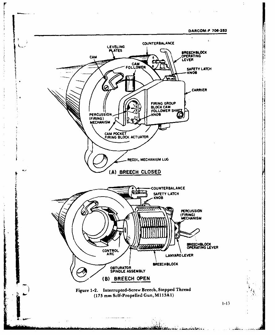
Breech ?tructures that can fulfill these dual re- closely fitting block as shown in Fig. 1-2. Thisquirements are termed "mobile closures"; the breech type is also known under the equivalentdesignation applies to the breeches of all terminology of interrupted thread, slotted screw,weapons treated by the handbook. Among the or plug closure.numerous mobile closures tried (past, present, To obtain ease or speed of operation and to op.and deve!opmerotal), acceptable and truly dis- timize the motions needed to seat (or unseat) thetinct types are limited. This is not surprising block, other than normal, continuous ti.reads aresince the severity of the preceding requirements employed. Interrupted or sectored threads areon design cannot be overemphasized. A suc- used which require the exterior of thecessful breech design must not only meet such breechblock and the interior of the breech ring tobasic technical concepts but must also incorpor- be specially machined-with equal numbers ofate reliability, simplicity, and production threaded sectors in each piece, alternating witheconomy into that design. At the same time corn- longitudinal clearance channels (Fig. 1-2(B)).patibility with the several breech mechanism in- Depending on the number of sectors used in aterfaces must be maintained, particular .esign, the threaded areas are fully
Elaboration is given in the paragraphs that engaged (or disengaged) by rotation of the blockfollow to those relatively few, distinctive closure through only a small part of one turn. Hence, thetypes that reached operational status in Army ar- breech is conveniently locked (or unlocked); antillery. Among these, the interrupted-screw and operating mechanism imparts the necessarysliding-wedge closures are the most commonly limited rotary motion of the block. The pitch ofapplied breech designs for large caliber weapons, the threads is such that, under the force of theto date. The designer also is made aware of the propellant pressure, friction will prevent therole of developmental and experimental closure locked breechblock from rotating and openingconcepts on such weapons. When possible, the due to the component of the force along the screwmerits/demerits of the various closure types and threads (Ref. 18). Breech locks, however, arethe background whereby certain ones were re- commonly employed.jected or accepted are also treated. In modern weapon applications, the total
breechblock motion consists of two cycles:1. The rotary motion and a pivotal, hinge mo-
1-5.1 INTERRUPTED SCREW tion that exposes the chamber for loading afterTwo truly distinct breech types with a long the closure threads have been unlocked.
record of acceptance remain in use today. In one 2. The motions take place in the reverse order
of them the closure principle centers around the after the weapon is loaded.basic mechanical locking device, the thread. Sine- Suitable clearance cuts, made in both theply, the structure is composed of an outer compo- breechblock and ring, to permit the hinge mo-nent or breech ring attached to the gun tube,and tion, can be seen in Figs. 1-2(B) and 2-20(C).an inner component or breechblock which (Older, heavy gun designs employed a three.-engages the ring through a specialized thread cycle breechblock motion, wherein the block wasdesign. The breech ring in conjunction with the not swung directly into or out of its seat in the ,, Krear of the tube assembly forms the breech recess breech recess; breechblock proportions requiredand provides access to the weapon chamber for an intermediate translating motion along the
1-12
DARCOM-P 700-253
COUNTERBALANCE
BREECH BLOCK
LEVERCAM,
FOOE
4 (A BRECH BLOSEDCA
OPERTINGLGVE
(B) BREECH COPEN
Figre -2.Intrrutedscrw Beec, tepped Threa(17 m Sef-roplldGnMiSAFEYLATC
KNOB3PECSSO
DARCOM-P 706-253
chamber axis to make the hinge motion possible. In Army usage, the interrupted-sci'ew breechThus, operating mechanisms were necessarily has generally been applied in weapons of 155more complex.) mm size and larger. This breech mechanism is
Breechblock motions are produced in one con- especially well suited to separate-loadingtinuous cycle when the operating mechanism is ammunition-particularly from the standpointsactuated. A support member-the block of ammunition handling and obturation. Sincecarrier-facilitates the action by supporting the ammunition traditionally has been of thebreechblock and connecting it to the breech separate-loading type for such calibers, a highouter structure (Fig. 1-2(A)). The carrier ai!ows degree of ammunition-breech (-.mpativility is
the block to be rotated with respect to the ring realize). However, the closure principle is notand provides the hinge axis for further motion to absolutely limited to one ammunition type-expose the chamber. The operating mechanism older, foreign ordnance applications using casedperforms yet another important function. When rounds and recent Army developments with un-the breech is open it prevents further rotation of conventional (consumable case) ammunitionthe block; 'this maintains proper alignment be- and substantial breech redesign can be cited (seetween threaded sectors and clearance channels par. 1-5.3).that must mate as the block is swung into or out A relatively modern example of the interrupt-of the breech recess. A spring loaded counter- ed-screw breech as used on the self-propelled
balance device smooths the hinge motion and weapon system 175 mm Gun, MI13AI/8 in.aids the actuating effort. Howitzer, M2A2, is shown in Fig. 1-2.
Both horizontal and vertical (downward) Specifically the closure is a Welin, two stepped-hinge motions have been designed, but the latter thread type (see also Fig. 1-7(C)). Structuralare identified with older, very heavy caliber, im- components discussed earlier-such as themobile weapons. Hinge motion in or close to Ehe breechblock, breech ring, and block carrier-arehorizontal plane represents recent Army design indicated in Fig. 2-20. This figure aiso illustratespractice-the block opening to the right side portions of other mechanisms treated elsewherewith an observer facing the breech. With regard and their typical arrangement-e.g., operating,to the thread form itself, various types have been firing, and obturating mechanisms.utilized, among them the buttress, modified V, According to Ref. 18, principal advantages ofand square forms. These thread varieties are the interrupted-screw beech are strength, more
* treated irt detail in par. 2-28. uniform distribution of the longitudinal stressSevtral variations of the interrupted screw ex- produced by the propellant, and relative ease of
ist; these are design alternatives taken either to obturation. The closure does not lend itself toimprove the closure strength or optimize breech automated functions-especially by power inter-opening and closing. Absence of threads in the nal to the weapon-and therein lies its ,-hief dis-clearance channels makes for loss of strength that advantage. But no matter what the power source,is inherent in the interrupted screw closure prin- automation is not readily obtained; the situationciple. However, the loss is compensated ty in- is obviously more complex when two distinct mo-creasing the length or surface area of thread tions are involved, in contrast to a single linearengagement. Par. 1-6,1 and Fig. 1-7 describe motion for the sliding-wedge breech.structural variations of the interrupted screwclosure that have evolved, namely: 1-5.2 SLIDING WEDGE
1. Single-cut threads Another elementary mechanical locking2. Conical taper threads (Bofors) device-namely the wedge-acts as the closure3. Stepped threads (Welin). in the sliding-wedge breech. Together with the
1-14
'"Ii
DARCOM-P 706-253
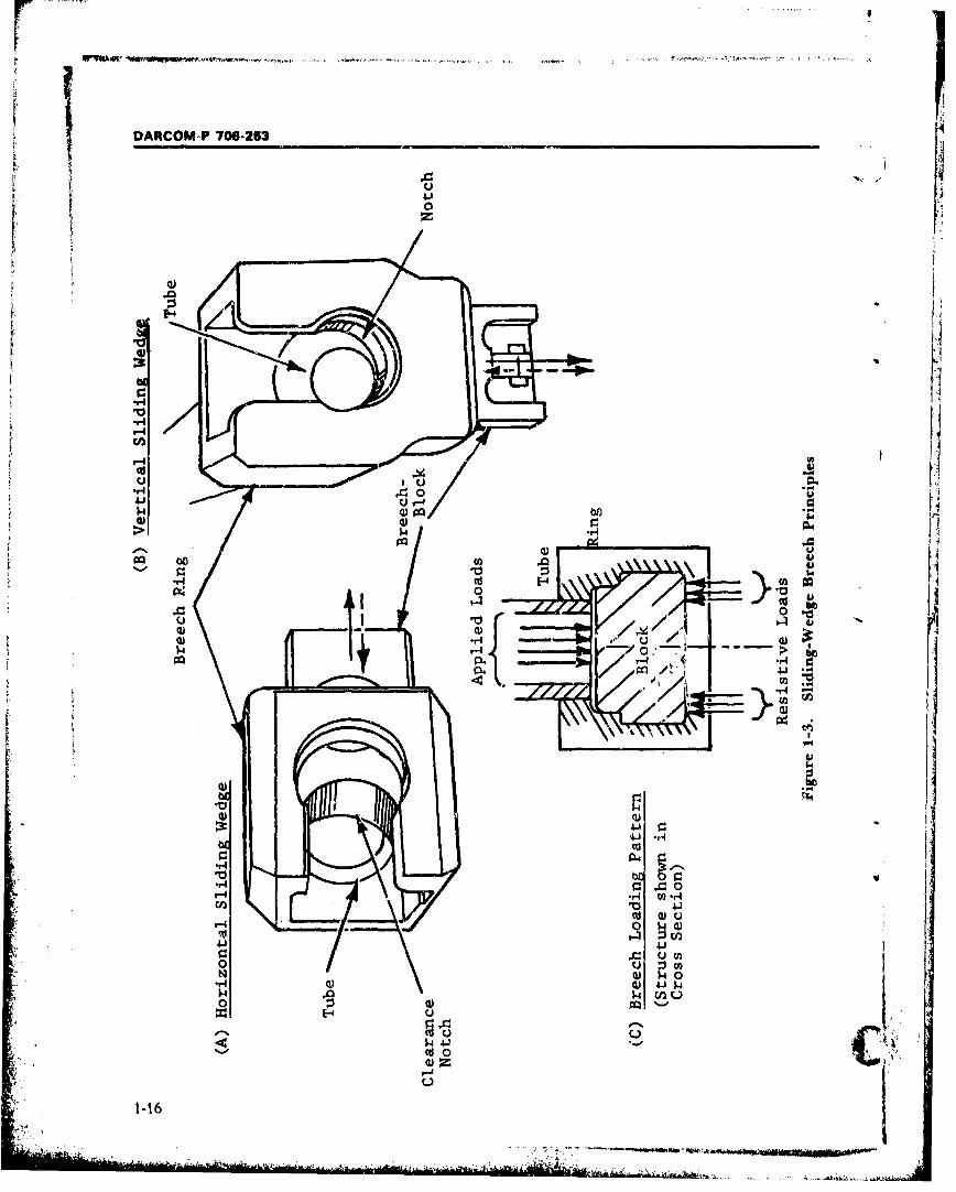
interrupted-screw closure (par. 1-5.1) the best suited to cased amipunition. The metallicsliding-wedge type is one of two basic designs cartridge case associated with fixed, semifixed,that is both long lived and yet currently used. A and separated rounds provides the necessary gasbreech ring attached to the rear of the gun tube seal-since obturation is not inherent in theassembly makes up the outer structure of the closure, nor easily adapted to it. Obturation ismechanism. Two major slots are machined in the treated separately in par. 1-6.6."ring". One, oriented axially, forms the breech Consequently, Army applications of thisrecess and exposes the chamber for loading and breech type have been limited to those weaponcase extraction. A second slot-perpendicular calibers where cased ammunition is availableand interconnected to the first-runs completely (traditionally not over 120 mm). Despite the dif-through the ring to provide "ways" or "tracks" ficult techniques involved in effecting a propel-for the breechblock (Fig. 1-3). The breechblock lant gas seal, there is interest in adapting the
* fits into the slot and slides on the ways between sliding-wedge breech to bagged ammunition.the open and closed breech positions when ac- The potential of simpler motions and more rapidtuated by a suitable operating mechanism. Ac- acting mechanisms at larger calibers are obviouscording to recent design practice, the through motivating factors. This principle previously hasslot and consequently the breechblock cross sec- been applied in a few gun designs of foreign ar-tion are roughly T-shaped. The slot shape is so mies. A more recent, significant application is theoriented that firing loads are resisted along the British CHIEFTAIN tank employing a sliding-top or cross of the "tee", as indicated by Fig. 1- wedge breech and separate-loading ammunition3(C). (Older sliding-wedge closures relied on a in its 120 mm gun. The weapon is in service, but amore complex geometry of block grooves and design departure of this kind is not without in-mating projections in the breech recess.) herent complexities, aside from the nonstandard
Major variations of the sliding-wedge closure obturating mechanism necessary-which isarise from the direction of breechblock motion further identified in par. 1-6.6-a separate meanswithin the ring. Block motion is to the right when of firing the bagged propellant must also be pro-the breech is opened in the horizontal sliding vided. The CHIEFTAIN tank gun incorporates awedge, while in the vertical sliding wedge-also feature whereby the primer cartridges are fed au-known as the dropblock-motion is downward tomatically into the firing mechanism (Ref. 17).(Figs. 1-3(A) and (B), respectively). In either sit- Recent Army activities along these lines are de-uation, the block moves with a one-cycle linear velopments to adapt the sliding-wedge closure tomotion and therein lies the main ad-vantage of the larger caliber weapons that fire separate-loadingclosure. It is well suited to breech operation in a ammunition.semiautomatic mode, allowing use of actuating The wedge closure principle is utilized by in-mechanisms that are relatively simple and rapid clining both the breech ring guide tracks andacting. mating contours of the block slightly forward of
Additionally, the block travel distance is mini- the breech face plane; a common wedge angle ismized by cutting a semicircular clearance notch 1.25 deg. Therefore as the block moves to theat thc end of the block nearest the chamber. closed or firing position it also advances slightlyLoading of the weapon or case extraction can, toward the breech face. This action plays a partthen, take place as soon as the breechblock notch in the ammunition-breech interface. Full seatingclears the bore. diameter-thus, total travel dis- of the cartiidge is assured when the block istance is not much greater than one bore closed-if the round was not completely inserteddiameter. Moreover, the sliding-wedge breech is in loading-by the beveled, upper part of the
1-15
- , . • -. . . . .. .. . . . ... .. . . . . . . .. : .•, • . .. .. .. . . ,• ,
OAFICOM-P 706-253
Uz
*-P4
'-4
41 u
CIO> -44
0
14.4- e 14 Uoo 0.
0 U0 -H U) V1-16 j
-,*d.
.. ~... 0
OARCOM-P 706-253
block front true. The sequence of events is shown oriented to tap off recoil motion for breech auto-schematically in Fig. 1-4 for a vertical sliding- mation.wedge breech. In the closecd position, a small ax- Operating mechanisms that perform theia! space must be left between the cartridge base various system functions-.pen and close theand the block front face to avoid jamming. Tbis breech, provide lockouts at either extreme ofdimension termed head clearance, generally motion, and work in conjunction with othervaries between 0.010 and 0.025 in., indicative of mechanisms-take on different arrangementsthe close tolerances necessary in breech corn- depending on block travel direction and whetherponent manufacture. breech actuation is manual or semiautomatic via
Both the horizontal and vertical design ver- recoil motion. Operating, firing, safety, and ob-sions are currently in use. Conclusive advantage turating and extracting mechanisms applicablecannot Le given to either block travel directibn. to the sliding.-wedge breech receive specific treat-Much depends on the particular weapon spoil- ment in pars. 1-6.2 to 1-6.5 and Chapter 2, See-
cation, space constraints, or considerations of tion IV. Since thie sliding-wedge and inter-gur, c.rew convenience. A very important guid- rupted-screw breeches currently comprise almostance criterion is that the open side of the breech every large calib'!r weapon, application, theirring must be located for maximum convenience salient features are summarized and compared inwhen loading the gun. Hcrizontal block motion Table 1-3.is generally used on towed weapons, wherelateral space is more readily available for the 1-5.3 SEPARABLE CHAMBER
sideways motion of the block and the breech The third type of large caliber weapoit breechoperating handle. A prominent exception is the in use today is a combination of previcus, well ac-vertical slide breech of the 105 mm Howitzer, cepted concepts and modern design additionsM102 (Table 1-1). Horizontal motion, often used produced with the current state of technology. Itfor manual breech operation, offers a relatively is used on the 152 mm Gun/Launcher (M81 andconstant actuation effort since gravity does not M162) designed for tank and armored recon-act directly on the block motion. Other factors naissance vehicle missions. This breech is similaralsC favor the hand operating mode-depending in some ways to the interrupted-screw type (par.
on weapon caliber (hence block weight)- 1-5.l)---e.g., the sectored-thread locking methodefficient manual actuation is nevertheless between the mobile and stationary parts of theachieved; a counterbalance device is not neces- breech structure is the same-but distinctsary; and not least in importance, design simplic- enough to carry a separate designation. In the
* ity is maintained, context of this handbook, the breech is referred toIn tank guns, vertical travel of the block is used as the separable chamber type. ("Pivot" or
most often, although a number of dated contra- "split" chamber are other less preferred, infor-dictions can be found. More stringent space real designations.)limits in a turret often demand that the "drop" The breech is a recent development created torather than sideways motion be used. A counter- fill the military need for weapon systems that canbalance device (one of several spring forms) is in- project both a consumable case round and. acluded in the actuating mechanism to smooth guided missile from the same tube. It exempli-gravity effects on the breechblock; the spring is fies the most refined use of external power forcharged during the opening or downward mo- breech actuation in a larger caliber weapon toI ... tion and assists upward motion by releasing date. Liberal use of power is in response to re-energy. Vertical block motion is also better quirements of the special ammunition, turret
1-.17
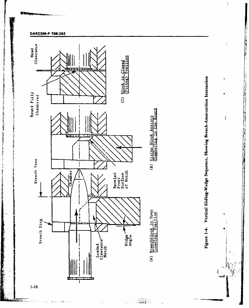
DARCOM-P 706-253
0 r
W~4J
C.)U 4Jffl r. 4
:3 -40
re..
Ca 00 0) 0
0 z
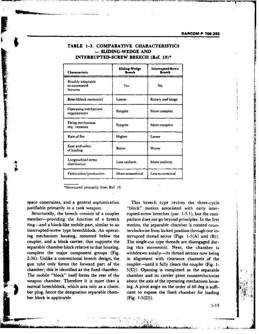
DARCOM-P 706-253
ITABLE 1-3. COMPARATIVE CHARACTERISTICSS- SDING-WEDGE AND
INTERRUPTED-SCREW BREECH (Ref. 19)*
Sliding-Wedge interrupted-ScrewCharacteristic Breech Breech
Readily adaptableto automated Yes Nofeatures
Breechblock motion(s) Linear Rotary and hinge
Operating mechanism S er xrequirements Simpler More complex
Firing mechanism Simpler More complexreq: ;rements
Rate of fire Higher Lower
Ease and safety Better Worseof loading
Longitudinal stress Less uniform More uniform
Fabrication/production More economical Less economical
*Structured primarily from Ref. 19.
space constraints, and a general sophistication This breech type revives the three-cyclejustifiable primarily in a tank weapon. "block" motion associated with early inter-
Structurally, the breech consists of a coupler rupted-screw breeches (par. 1-5.1), but the corn-member-providing the function of a breech parison daes not go beyond principles. In the firstring-and a block-like mobile part, similar to an motion, the separable chamber is rotated coun-interrupted-screw type breechblock. An operat- terclockwise from locked position through one in-ing mechanism housing, mounted below the terrupted thread sector (Figs. 1-5(A) and (B)).coupler, and a block carrier, that supports the The single-cut type threads are disengaged dur-separable chamber block relative to that housing, ing this movement. Next, the chamber iscomplete the major component groups (Fig. withdrawn axially-its thread sectors now being2-36). Unlike a conventional breech design, the in alignment with clearance channels of thegun tube only forms the forward part of the coupler-until it fully clears the coupler (Fig. 1-chamber; this is identified as the fixed chamber. 5(Q)). Opening is completed as the separableThe mobile "block" itself forms the rear of the chamber and its carrier pivot counterclockwiseweapon chamber. Therefore it is more than a about the axis of the operating mechanism hous-
- ~ normal breechblock, which acts only as a chain- ing. A pivot angle on the order of 60 deg is suffi-ber plug, hence the designation separable chain- cient to expose the fixed chamber for loadingber block is applicable. (Fig. 1-5(D)).
1-19
S! • I ,,... . .... ... .. -•--7:I. :: . -," - - - - "-
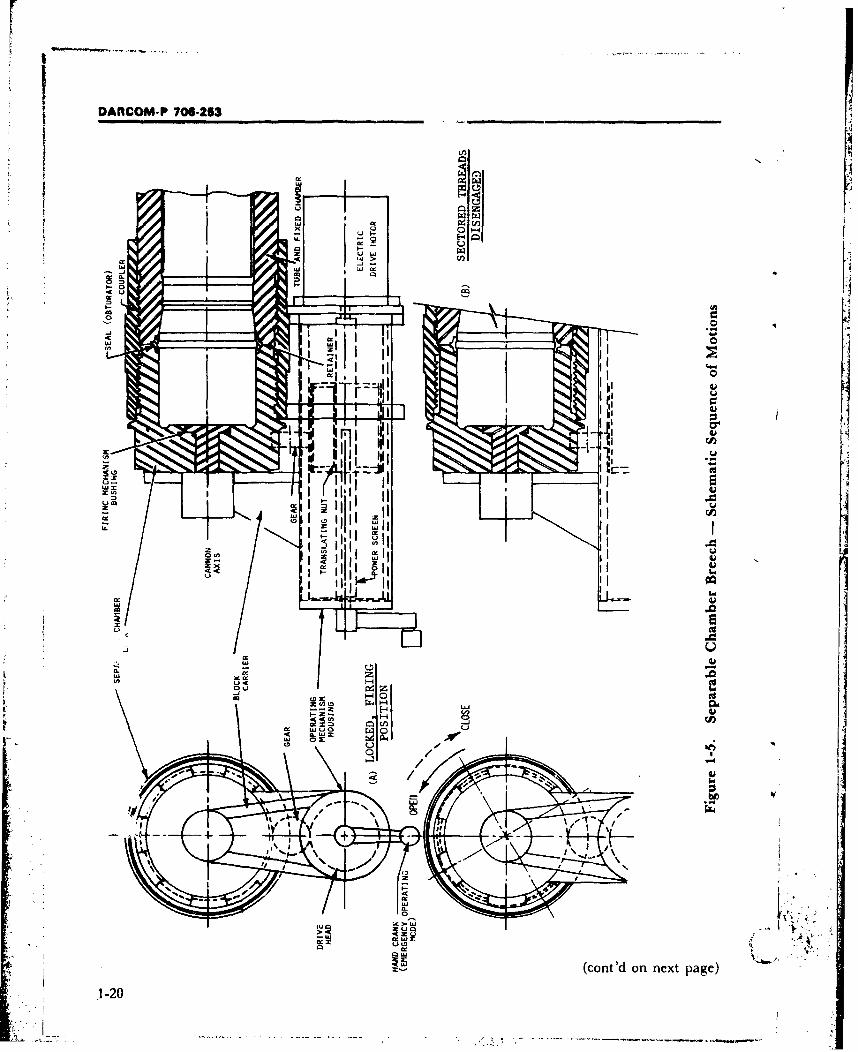
DARCOM-P 706-253_________ _______
o~r-4
oCCIO
WXA
ro
cc.z0
u0
IIz
.41
C4 z
-K -K )i
1-20
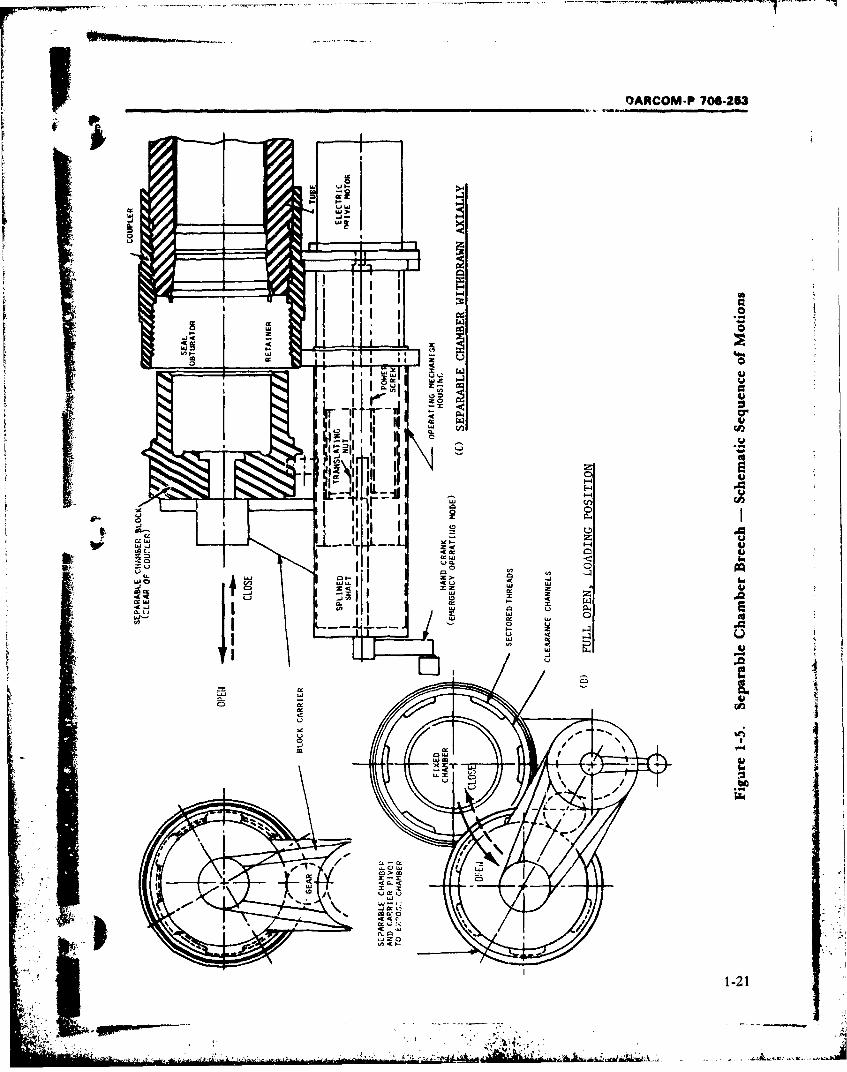
QARCOM-P 706-253
U -1
~- #-
ujj I
9--7.9~iI .a. a:
6p 0iL4K 0 QCDi
IfI
ILL
1-21
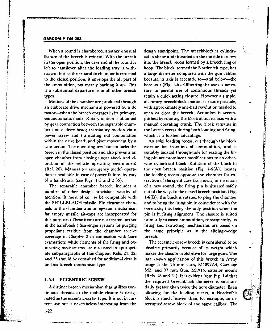
OARCOM-P 706-253
When a round is chambered, another unusual design standpoint. The breechhlock is cylindri- ,,feature of the breech is evident. With the breech cal in shape and threaded on the outside to screwin the open position, the case end of the round is into the breech recess formed by a breech ring orleft to cantilever after the loading tray is with- hoop. The block, termed the Nordenfelt type, ha3drawn; but as the separable chamber is returned a large diameter compared with the gun caliberto the closed position, it envelops the aft part of because its axis is eccentric to-and below-thethe ammunition, not merely backing it up. This bore axis (Fig. 1-6). Offsetting the axes is neces-is a substantial departure from all other breech sary to permit use uf continuous threads yettypes. retain a quick acting closure. However a simple,
Motions of the chamber are produced through all rotary breechblock motion is made possible,an elaborate drive mechanism powered by a dc with approximately one-half revolution needed tomotor-when the breech operates in its primary, open or close the breech. Actuation is accom-semiautomatic mode. Rotary motion is obtained plished by rotating the block about its axis with aby gear connection between the separable chain- manual operating crank. The block remains inber and a drive head; translatory motion via a the breech recess during both loading and firing,power screw and translating nut combination which is a further advantage.within the drive head; and pivot movement by a An axial loading recess, cut through the blockcam action. The operating mechanism locks the exterior for insertion of ammunition, and abreech in the closed position and also prevents an suitably located through-hole for seating the fir-open chamber from closing under shock and vi- ing pin are prominent modifications to an other-bration of the vehicle operating environment wise cylindrical block. Rotation of the block to(Ref. 20). Manual (or emergency mode) opera- the open breech position (Fig. 1-6(A)) locatestion is available in case of power failure, by way the loading recess opposite the chamber for ex-of a handcrank (see Figs. 1-5 and 2-36). traction of the spent case (as shown) or insertion
The separable chamber breech includes a of a new round; the firing pin is situated safelynumber of other design provisions worthy of out of the way. In the closed breech position (Fig.mention. It must of co *se be compatible with 1-6(B)) the block is rotated to plug the chamberthe SHILLELAGH missile. Fin clearance chan- and to bring the firing pin in coincidence with thenels in the chamber and an ejection mechanism bore axis; this being the only position when thefor empty missile aft-caps are incorporated for pin is in firing alignment. The closure is suitedthis purpose. (These items are not treated further primarily to cased ammunition, consequently, itsin the handbook.) Scavenger systems for purging firing and extracting mechanisms are based onpropellant residue from the chamber receive the same principle as in the sliding-wedgecoverage in Chapter 2 in connection with bore breech.evacuation; while elements of the firing and ob- The eccentric-screw breech is considered to beturating mechanisms are discussed in appropri- obsolete primarily because of its weight whichate subparagraphs of this chapter. Refs. 21, 22, makes the closure prohibitive for large guns. Theand 23 should be consulted for additional details last known application of this breech in Armyon this breech mechanism type. usage is the 75 mm Gun, M1897A4, Carriage
M2, and 37 mm Gun, M1916, exterior mount(Refs. 18 and 24). It is evident from Fig. 1-6 that
1-5.4 ECCENTRIC SCREW the required breechblock diameter is substan-A distinct breech mechanism that utilizes con- tially greater than twice the bore diameter. Even
"tinuous threads as the mobile closure is desig- allowing for the loading recess, a Nordenfelt 4nated as the eccentric-screw type. It is not in cur- block is much heavier than, for example, an in-rent use but is nevertheless interesting from the terrupted-screw block of the same caliber. The
1-22
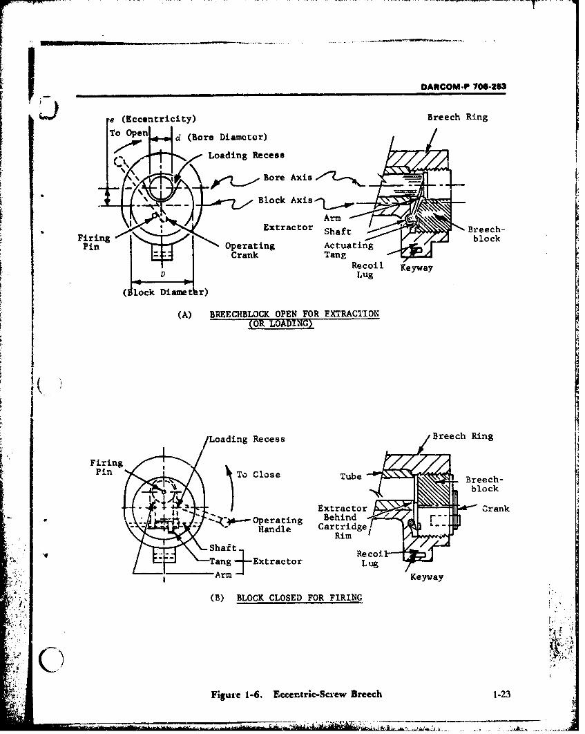
OANCOM-P 706-253
e(Eccentricity) Breech Ring
To Open d (Bore Diamotor)
"i ,Loading Recess
Bore Axis -.--- -
* -Block Ai
ArmExrctr Shaft Breech-
Firing blockPin Operating Actuating
E+JCrank TangDRecoil Keyway
(Alock Dian~ r)
(A) BREECHBLOCK. OPEN FOR EXTRACTION
(OR LOADING)
/Loading RecessBrehRn
K FiringPin ToCoeTb Case TubeBreech- '
'.i--Operating BehindzCartridge,
RimShaft
- ~ ~ n ExtrI ; acdle ExrctrblcArm Kya
(B) BLOCK CLOSED FOR FIRING
Figure 1-6. Eccentric-Screw Breech 1-23
DARCOM-P 70-253
ponderously large breech ring must also be con- A number of experimental breech conceptssidered in a weight assessment. Revival of at least have been advocated in recent years, but none ofa similar principle is evidenced in experimental them has attained acceptance. Still, such devel-weapons of recent vintage that utilize rotary opmental and experimental closure types repre-(multiple) chambers. sent useful information to the designer-
recording methods of approach previously tried;1-5.5 DEVELOPMENTAL AND offering possibilities to be improved on; or in-
EXPERIMENTAL CLOSURE dicating the point of departure for fresh concepts.
CONCEPTS Refs. 5 to 8, 25, and 26 record examples of ex-The foregoing paragraphs describe those perimnental breech concepts. Refs. 25 and 26 deal
relatively few breech closures which have at- with tank and self-propelled weapon applica-tained operational acceptance, the designer's ul- tions, for consumable case rounds, exclusively.timate goal. In part, the small number of suc- Refs. 5 through 8 involve towed weapons usingcessful designs testify to the stringent require- conventional ammunition but containments and severe operating environment im- worthwhile reference material on rapid fire con-posed on breech mechanisms; but more is in- cepts and automation of loading/feeding steps.volved. Substantially new breech designs enmerge While the sources cited are representative, theyonly in accord with the str'us of ordnance tech- do not exhaustively portray the amount of worknology to produce those designs and the ammu- done in the area.nition to be projected. For conventional ammu-nition (pars. 2-11.1 to 2-11.3), the sliding-wedge•' 1-6 MECHANISM AND COMPONENTand interrupted-screw closures fulfill a role thatis unlikely to be challenged. Of course, develop- BREAKDOWN
ments are continually underway to upgrade, The brecch system of a large caliber weaponrefine, and otherwise improve functional per- comprises a number of mechanism subassem-formance within these basic breech types. blies and major components. These constituent
However, progress within the ammunition elements can be broken down into logical group-
field and availability of unconventional rounds ings, generally along lines of the functions they(pars. 2-4 and 2-5) are most responsible for the perform within the system-i.e., breech struc-demand for newer closures. Development of the ture/ciosure, operating mechanism, firing mech-previously described separable chamber breech anism, extractor, or obturator. It is also useful tois an explicit illustration of the influence of un- make a mechanism breakdown for the purpose of
conventional ammunition. Probably the one fac- discussion.tor that imposes the most sex'ios new design Important breech mechanism subassembliesproblems is the practical reaiiy J. the con- and major components are treated in the remain-sumable case round. The d&sign challenges are ing subparagraphs of this section. The two basic,nevertheless undertaken because their solution but distinct breech types-sliding wedge and in-offers the potential of improved weapon perfor- terrupted screw-are used throughout the dis-mance. Depending on the particular experi- cussions, reflecting their importance relative tomental breech concept, improvements due solely breech design technology as a whole. Forto the consumable case may be sought- hardware considerations, the 105 mm Howitzer,handling, loading, spent case elimination, M101A1, and the 175 mm Self-propelled Gun,stowage, etc.--or the design maw also strive to in- M1 13A1. serve as prime examples--representa-crease firing rate, reduce weapon weight, or tive of those breech types, respectively.make better use of restricted fighting compart- Naturally, other weapon types and calibersment space. receive treatment, consistent with the scope of
1-24
7-+ -- .., .-
DARCOM-P 706-253
the handbook, deifending on their further con- design practicalities. Six threaded sectors weretribution to des.in ,suidance or state of docu- commonly used for the single-cut block.raientation. By giving the breechblock a conical taper with
diameter substantially increased toward the rear,1-6.1 BREECH STRUCTURE/CLOSURE thread area is enlarged allowing the block to be
Major structural e ements of the breech consist shortened. This form of interrupted screw isof a breech ring o- stationary part; a breechblock commonly referred to as the Bofors closure (Fig.or mobile part; arnd,' depending on the type of 1-7(B)) but in a strict sense the threads arebreech, other supporting members that guide the single-cut. The original shape improves on theblock motions. The"iring forms the breech recess, right cylindrical form (for the same materialprovides a recer~tacle for locking the block into strength) but a small lincar retraction is stillplace, and also ;erves ai the interface componeht necessary to permit hinge motion (Ref. 27); fa-between the breech and tube assembly, brication difficulties are also obvious. Other
The moving n, of the structure blocks or functional relations of the Bofors closure areplugs the chaYtb.fr opening, hence the term similar to those for case A (Fig. 1-7); this closurebreechblock is al:,pli td equally to wedge, screw, type has not been recently applied.and even separable chamber closures, although Stepped-thread construction permits moreparts of drastically different configuration are in- than 50% of the block surface to be used forvolved. However,, in the separable chamber thread engagement. One clearance channel andbreech, the block actually forms the rear portion two or more threaded sectors of increasingof the chamber as the nomenclature implies, diameter are formed in repeating sequenceBoth the interrupted.screw and separable chain- around the block periphery. The channel and
L.J ber closures have a black carrier, as part of their threads are oppositely arranged in the breechstructure, to suppoi the block while it is swung ring, hence block rotation through an angleout of the breech recess. Although block motions equal to only one sector locks or unlocks the
: are very different in these breeches, th, carrier closure. This interrupted-screw variety, alsoassembly performs the same suppor. role as a known as the Welin type, enjoyed a favored rolecomparison of Figs. 1-5 and 2-21 will indicate, in modern weapon design, and only the very
The in-,-.rrupted-screw breech, in particular, latest weapon applications have replaced it (e.g.,presents additional structural details that are the 155 mm Self-propelled Howitzer, M126A1,worthwhile to record. These details center and 152 mm Gun/Launcher, M81 or M162).around the manner in which the closure threads The Welin type thread is superior to its prede-were interru'pted 'in the evolution of this breech cessors since it permits use of a shorter breech-type. Design variations are best described con- block; consequently, the block can be swung outsidering the breechblock alone, of the breech recess directly. Block length can be
The original block had simple, single-cut reduced when diameter (or thread area) is in-threads (Fig. 1-7(A)). For an outside diameter creased, depending on other design trade-offs.D-somewhat greater fA:an a given bore Both two and three "steps" of threads have beendiameter d-thread length L was required for a used (Figs. 1-7(C) and (D), respectively); offixed level of strength. Regardless of the number course, the outside diameter of the block in-of sectors, thread engagement area cannot ex- creases while rotation angle decreases with theceed 50% of total surface area in this design. The number of stepped-threads employed. An exam-rotation angle necessar;: .o lock (or unlock) the pie of the two-step, Welin interruoted-screwbreech is inversely proportional to the number of breech is found on the 175 mm Self-propelledsectors; the latter are go,.erned naturally by Gun, Ml13A1 (Fig. 1-2(B)).
1-25
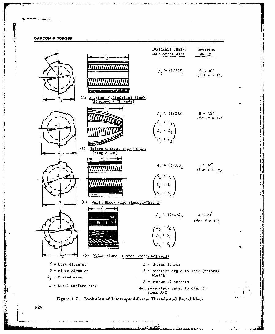
DAMCOM-P 706-253 I
AVAILAbLE THREAD ROTATIONENGAGEMENT AREA ANGLE
',,A % (1/2)S6 0 '1, 30Oa . t A (for X - 12)_
(A) Or~igi Cylindrical Block
ASn' 1 le-Cut Threads)
BAt . (112)S 6 %t 30 'Bl (for N - 12)
L LB < LA A
B ")A
(B) Bofors Conical Taper Block
(Single-Cut)
L
'At A (213)S_ e ,%, 30_t C (for N 12)
S 1:> SA
DD < LA
(D, > IC,
D (C) Welin Block (Two Stepped-Thread)
At (3/4)Strat ae 2a3
(for N 16)
D C
s cD
DFD (D) Welin Block (Three Stepped-Thread)
d - bore diameter L - thread length
D = block diameter 0 - rotation angle to lock (unlock)
A - thread area breech
N = number of sectorsS = total uurface area A-D subscripts refer to dim, in
Views A-D)
Figure 1-7. Evolution of Interrupted-Screw Threads and Breechblock
1-26
l1
DARCOM-P 706-253
At the same time, the stepped-thread closure 1-6.2 OPERATING MECHANISMmakes for a complex breechblock surface. The One of the most important mechanism sub-piece is inherently difficult to produce. Manu- groups within the total breech system is thatfacturing efforts and costs previously accepted, which opens and closes the breech-whether bylacking a better alternative, are now being recon- manual or automated means. Operating mecha-sidered for the latest weapons. In the current nisms have characteristics associated with thedesign approach several developments are com- particular type of breech they serve. To date,bined to produce a modern single-cut, sectored- nearly every application of a semiautomaticthread breechblock, no larger than a stepped- breech makes use of power internal to thethread block of equivalent caliber. This is made weapon. This limits the designer's latitude inpossible by use of newer, superior block choosing operating mechanisms to those that arematerials, sectored-thread forms optimized for most compatible with recoil energy. However,strength; and efficient fabricating processes. Em- mechanisms which operate the breech manuallypirical investigations and dynamic simulation or semiautomatically differ largely from the ac-tests conducted on thread configuration are sig- tuation method utilized rather than in underly-nificant factors in arriving at a suitable design. ing principles. Design details relative to the in-These techniques and their important results are k-i'rupted-screw and sliding-wedge breech typestreated in pars. 2-27 and 3-17.7. Because of the are provided in Chapter 2, Section III.general trend to fewer numbers of weapons, ap- When external power is available fo" breechplication of the new breechblock with single-cut actuation, the operating mechanism can takesectored-threads is still limited (Table 1-2). more varied forms in accordance with other de-
The design of structural elements must also in- sign trade-offs. The primary example of anclude provisions to house or locate the remaining externally powered semiautomatic breech isbreech system mechanisms. For example, the fir. found in connection with the separable chambering mechanism and obturator typically are con- breech (used on the 152 mm Gun/Launcher,tained in the breechblock; while the operating M81 and M162). The operating mechanism Tormechanism is anchored to the breech ri', Still this breech type is treated in par. 1-5.3.other mechanisms may be located in either themoving or stationary parts of the breech 1-6.3 FIRING MECHANISMstructire-or made to function by both of them. All breech system elements that take part inExampies in this category are safety interlocks initiating the primer comprise the firing mecha-and extractors, respectively. The principal nism. However, the makeup of that total mecha-breech types are treated individually in pars. I- nism is a substantial variable influenced by:S.1 to 1-1.4. Since closure designs are covered in i. Type(s) of ammunition to be projecteddetail, structural components receive attention 2. Kind of breech system and its operatingsimultaneously in those paragraphs of the modehandbook. Illustrations found in pars. 1-5 and 2- 3. Particular requirements of different weaponS11 also provide a significant complement to the applications, which incidentally are not staticforegoing discussions; the designer is encour- witli time,aged to cross-reference with Figs. 2-14, 2-20, Perhaps these are the reasons why terminology2-23, 2.25, and 2-32, particularly, for the best un- and even equipment classification relative to fir-derstanding of mechanism and structural rela- ing mechanism design have been found quite in-tionships. consistent or misleading (Refs. 1, 2, 10-13, and
1-27
DARCOM-P 70oE-253
24). On one hand, a component group that per- readily available power, or more cumbersomeforms only a part of the firing cycle is too often alternatives. Railway and seacoast artillery fixedtermed as "the firing mechanism". At the op- guns represent early Army applications of electposite extreme, an assembly which carries cut a tric firirpg mechanisms. With the emergence ofset function (e.g., the percussion mechanism) modern, mobile artillery, advantages diminishedmay have several different designations from for electrical systems available at that time; theyweapon to weapon, although working under the were not sufiiciently competitive for the trend tosame principle. In short, distinct mechanism smaller weapons. It was Naval ordnance that Ltypes are fewer in number than their descriptive took up serious development of electric firingnomenclature. mechanisms, having both a more suitable battle
Mechanism type is best classified according to environment and weapons of more applicable 'the manner of primer ignition but, as already in- caliber.dicated, this function does not necessarily fulfill Improvements in reliability brought electric
all requirements of a total firing group. This is firing back into modern Army ordnance by wayespecially evident in a firing mechanism thaL of the electric-percussion system. This dual firingmust accommodate a separate primer. To date, mechanism (also referred to as "electric or iner-
only three basic firing mechanisms have reached tia") was employed on a few self-propelledSacceptance--percussion, electric, or their corn- weapons of large size; e.g., 8 in. Self-propelled
bination. They have the following general char- Howitzer M47, M55 Vehicle (also see Tables 1-1
acteristics: and 1-2). In this firing mechanism, electric igni-1. Percussion. The primer is physically struck tion is the primary mode, with the percussion
and indented by a pin. An internal power source device serving a backup role. If the special primer(one or more charged springs) supplies the fails electrically, it still may be fired by the blow
energy. Several design variations and triggering of the firing pin. But the percussion element hay-methods exist, as elaborated hereafter. ing failed, thie primer will not fire electrically. A
2. Electric. The primer is initiated by electric relatively simple actuating circuit is used in
resistance generated heat. A special electric which an electric potential is developed acrossprimer and an external power source are re- the metal primer case.quired. More recent electric firing device applications
3. Electric-percussion. The mechanism con- for tube launched projectiles are equally scarce.
tains a firing circuit and also a separate percus- Parallel improvements in the percussionsion device to initiate a special dual-purpose mechanism continue to satisfy needs in most ap-primer. External power requirement is similar to plicatioris. Only new ammunition developmentsthe electric type. and the most tactically sophisticated weapon
system--the tank gun-demand ultimate refine-
ment in all functions. Scarcity of current exam-1-6.3.1 ELECTRIC AND ELECTRIC- pies is not an assessment of future trends but an
PERCUSSION FIRING indication of unresolved controversy of the elec-MECHANIaMS tric vs the percussion method even in tanks.
Traditionally, nonmechanical firing devices Table 1-2 cites two current examples of weaponshave been associated with separate-loading am- with electric firing mecha sisms on differentmunition, for which special required primers also models of the M60 Tank. "'he 105 mm Tankhad been developed. These firing mechanisms Gun, M68, repres-nts an unconventional situa-were used initially on very large size guns of the tion at this point ir time. It fires a special elec-
day-where convenience derived from an dec- trically primed rourd, requiring that type of fir-
trical method could be justified on the basis of ing device, but the ammunition is standard in
1-28
F.DAR.CM-P 706-253
other respects (fixed charge, metal cartridge immediately atcr primer indentation. -
case). the percussion mechanism does not require mo-
Consumable case ammunition provides the tion independent of the breechblock. (Con-other area of current demand for electric firing trasting requirements apply when designing formechanisms. The stringent and often unique re- bagged ammunition as described later.)quirements imposed on breech design by this An overall firing mcchanism consists primarilyammunition type are cited at numerous points in of cocking, percussion, triggering, and actuatingthe handbook-with reference to the 152 mm elements. These may be separately mounted toGun/Launcher System (M81 and M162). In- the breech or-all but the trigger actuator-deed, demands on firing mechanism design are housed in the breechblock in a common caseparticularly severe. A contact probe exposed to called the firing lock. Details depend much onthe chamber must withstand the high pressure, the specific weapon application, also on thethermal shock, and erosive effects of hot gases breech operating mode. The two illustrative ex-developed by the propellant. Adequate sealing of amples to follow--(l) the continuous-pull, per-
the probe to prevent combustion gas leakage is a cussion and (2) the spring actuated, inertia per-further problem area. In a typical firing device, cussion mechanisms-represent firing devicesshown schematically in Fig. 1-8, ignition current used with hand operated and semiautomaticis carried to the consumable primer by a fixed breeches, respectively. However, use of theseprobe, insulated from the breech. Contact is devices in a given mode is one of preference ormade through a lead wire spring located in the convenience rather than a fixed rule.primer. The circuit is completed to ground with While the "continuous-pull" type hasa second wire spring in the cartridge case base automated internal features, it is most(Ref. 25). Probe sealing is accomplished by the conveniently actuated manually by a lanyardcombination of close fit with the breech and an pull. Accordingly, it has been used on a numberelastic ring seal. of towed weapons-particularly those with a
Detailed treatment of electric firing mecha- horizontal sliding-wedge breech, where its- nisms, particularly for tube weapons that fire un- tiigger actuation technique is especially advan-
conventional ammunition-or have a dual mis- tageous. The "spring actuated, inertia" type hassile launching capability-are beyond the scope several attributes compatible withof this handbook. As outlined, the extent of such semiautomatic breech operation, hence it is usedapplications is still limited. However, the pres-, largely with the vertical sliding-wedge variety.ent, predominant role of percussion firing Therefore weapon applications include antiair-
mechanisms in large caliber weapons is further craft and tank guns as well as self-propelledelaborated. howitzers (see Table 1-2). In this device, the
trigger can be actuated by one of several means;1-6.3.2 PERCUSSION FOR CASED actuation by a solenoid is quite convenient (see
AMMUNITION Fig. 2-26) when prompted by tactical or
In Army practice, conventional cased am- technical requirements. It should be emphasizedmunition (par. 1-4.3) is fired from the sliding- that the percussion firing method remairns com-wedge type breech, exclusively. The general sim- pletely unaltered when the spring loaded device,plicity of breech operation carries over into the carrying the firing pin, is released and latchedfiring function and into the mechanisms that ac- electrically.commodate it. No part of the device feels the full All percussion firing mechanisms, regardless ofeffect of propellant energy release since the set- type, have a number of common performance re-back force is taken by the breechblock through quirements. The firing pin must operate withinthe cartridge base-the firing pin being retracted specified limits of travel. Such factors as pin
1-29
- -. ,.. -.... '•-,: ... . -:..• ". ..
DARCOM-P 706-253
k 0
r4r
cn E-4
cd Q)r-4 41 Q
.r4 I=
$4U
too1
/0AU
ci-
1 0 0
0r4 cir4
CIC1
41 Q) 9
E-44-4
p 40 *r 4~U)4
1-30
- .* -~L
DARCOM-P 706-253
S.P protrusion from the block, retraction therein, and For equally large but newer self-propelledalso pin centrality with respect to !he primer are weapons, a drastically different firing mechanismset as determined from the breech-tube- is necessary. A case in point is the 175 mm Gun,ammunition interface dimensions. Firing pin MI13A1/8 in. Howitzer, M2A2, self-propelledprotrusion, for instance, is a function of the head weapon system (Table 1-2). Here, a small scaleclearance present in a loaded breech. vertical sliding breechblock is employed as a sort
of firing lock. It contains the firing pin, but the1-6.,.3 PERCUSSION FOR SEPARATE- percussion device-a "continuous-pull" type-is
LOADING AMMUNITION a self-contained unit, separately housed in the fir-
A firing mechanism used for separate-loading ing block behind the pin. (Based on previousammunition is, to all intents and purposes, a metl.ods, it is difficult to assign an entirelycomplete miniature breechblock. Instead of correct and short designation to this firingoperating directly on a cartridge containing the group.) The total firing mechanism incorporatescomplete., full propelling charge, it is built on a several design refinements including automatedsmaller scale to operate with a primer cartridge extraction of the fired primer; the extractor
only-the firing of which ignites a black powder receives further treatment later. At this point it ischarge sewn on the rear of the separately loaded important to emphasize that automated func-propellant bag. Consequently, the firing device tions in the firing mechanism are not syn-for this ammurition type is complicated and sub- onymo,_3 with the breech mechanism operatingject to some different and more severe design re- mode as a whole. In the specific example' underquirements than its counterpart that initiates discussion, the breech itself is operated entirelycased rounds. Namely, these firing mechanisms by hand. Indeed, only one example of a semi-must: automatic interrupted-screw breech can be cited
1. Move independently with respect to the crrently. The 155 mm Self-propelled Howitzer,breechblock for insertion and closure of the M126A1, (M109 vehicie) is described in par. 2-separate primer, also for its removal when spent. 11.3.
2. Incorporate structures sufficient to resist Examples of the firing mechanisms that followpropellant energy effects directly, albeit acting are representative for design guidance, but do riotover a small primer chamber area. exhaust the field. Several other firing locks were
3. Interface with the breech operating designed in the past using the vertical sliding
mechanism for safety considerations (par. 1-6.4) block principle (for example the Firing Lock,and, depending on the weapon, to acquire a M17-Ref. 28). These were permanently at-degree of automation. tached to the breechblock; the primer was insert-
Firing mechanisms, for separate loaded am- ed manually, but operation of a firing lock handlemunition therefore, have been designed with con- automatically extracted the spent primer.siderable variety in elemental arrangement. Con- Electric-percussion firing mechanismns discussedtrasts are clearly drawn in twe, subsequent design earlier in this suoparagraph employed thisexamples. It is in this area also that special general type of device for the mechanical feature.problems of nomenclature arise. The percussion Consideration of pin protrusion, retraction,hammer mechanism is operated strictly by hand. and centrality-mentioned for c;ased ammuni-It represents an older design philosophy since the tion firing devices--applv equally well here.firing lock is completely removed from the breech Naturally, different dimensional limits apply 4',
between successive rounds. However, it is still in from one weapoi. to the next. However, an ad- i.
use, fulfilling a need for certain large, towed ditional requirement is imposed for mechanismsweapons (see Table 1-1). firing a separate loaded round, i.e., primer
1-31
DARCOM-P 706-263
headspace-the distance Uttween the Iuing block (This role is in addition to smoothing the transi-front face and the obturator spindle rear face- tion of the block between the two kinds of mo-
must be maintained between specified limits. tion.) A guide bracket, mounted in the breech(This is analogous to the dimensinnal require- recess swing clearance (Figs. 1-2(B) and 2-23,ment in a full scale sliding-wedge breech.) item KK), provides a datum surfac.. for one of the
block interrupted-thread sector flanks as it1-6.4 SAFETY INTERLOCKS swings out of the breech recess. Therefore, this
Those breech system parts and devices which component-called the control arc-retains thefunction to prevent dangerous occurences to the miesh registry necessary between the block andcrew or weapon constitute safety interlocks. It is recess.logical to incorporate such important provisions Safety interlocks are associated with all firinginto both the operating and firing mechanisms of mechanisms by designing such elements directlya breech. Treatment of s,"-ty features is provided into the device or are derived from their operat-in this subparagraph. ing procedure. Mechanisms for firing conven-
Most breech operating mechanisms employ tional cased ammunition have the inherent safetysome form of locking device at their closed or fir- of being in firing alignment only when the breeching position. For manually operated breeches, is fully locked, In applications using separate-this usually entails a simple spring-loaded latch loading ammunition, the primer is inserted last,
that is captured by a suitably located slot or behind a fully loaded chamber and lockednotch. The spring loaded male member can be breechblock. But that separate primer needson either the operating lever or breech outer access to the chamber; consequently, the breechstructure as illustrated, respectively, by Figs. 2- system is not completely sealed until the primer14 and 2-16 (horizontal sliding-wedge closure), is in place and its own small scale "breech" isand Figs. 1-2 and 2-23, items F, G,J, and L (in- secured. Comparative design problemsterrupted-screw closure). To release the s&,fety associated with firing mechanisms for the distinctlock, it is odly necessary to depress an operating ammunition types are discussed in pars. 1-6.3handle or withdraw a latch knob-depending on and 2-12. Specific safety features of the design ex-the particular design. amples presented are amplified in Table 1-4.
While the open breech position is not nearly as 1-6.5 EXTRACTING MECHANISMcritical, a positive method of holding the block After the firing of a projectile, an empty car-must be provided. For sliding-wedge breeches tridge case remains in the chamber of a gun firing(firing metal cartridge case ammunition in con- any ammunition except for consumable case andventional practice), the extractor devices take separate-loading types. Obviously, such spentcare of this function in their secondary role (par. cases must be removed from the weapon before2-13). In the interrupted-screw breech, toggle ac- the next round can be loaded. Parts of the breechtion of the counterbalance assembly is utilized system which carry out this function fit the term,(see Fig, 2-22). This device receives detailed "extracting mechanism". For fixed, semifixed,treatment in connection with operating mecha- and separated ammunition a full size cartridgeinisms. case in involved; and for separate-loading am-
Design of the interrupted-screw breech type munition, a much smaller cartridge. According-includes other controlling features which make ly, two broad extractor categories are recognized,the operating mechanism safe. The breechblock i.e.,roller and its mating cam (Figs. 1-2 and 2-20) 1. Those which handle actual full caliber casesprevent block rotation beyond that needed to and work with the sliding-wedge type breechclear the closure threads and maintain this at- 2. Those which work with primer cases in cer- .___ 1titude during the critical start of hinge motion. tain firing mechanisms of the interrupted-screw
1-32
• . : ::. A
DARCOM-P 706-253
TABLE 14. SAFETY CHARACTERISTICS OF TYPICAL FIRING MECHANISMS(These mechanisms are treated in detail in par. 1-6.3)
Firing Mechanism Type Safety Feature
Continuous-Pull, Percussion (with M 13 1. Firing pin is in proper alignment only when breech is fully locked.Firing Lock) 2. Firing pin is unseared only upon positive actuation - involving sub-
Z Ref. 3, pp. 2 39 and 240 stantial force and motion.0 Ref. 35 3. The mechanism is not cocked until the instant before firing.P ai4. It returns to firing position and is seared automatically.
5. In cases of misfire, the action can be repeated at will without exposingthe loaded chamber.
Spring Actuated, Inertia Percussion 1. SameFas above.Ref. 29 2. Firing pin is unseared only upon positive actuation of the trigger plunger.
3. In case of misfire, the mechanism may be recocked by hand (normallythis function is obtained automatically by virtue of breechblock motion).
4,5. Same as above.
Percussion Hammer (with M I Firing 1. A safety latch interlocks the operating and firing mechanisms:Block)Refs. 2 and 30 a When the block (M 1) is screwed into firing position, it displaces the
latch against the breech operating mechanism and the block cannotrotate open.
e When the firing block is removed (between successive shots) the latchmoves in the opposite direction allowing the breechblock to be opened,and bars access to the firing block housing. The open breech, in turn,locks out the latch.
2. A spring-loaded safety plunger on the firing block engages a notch inthe adapter (fixed to the carrier) to hold the block in firing position.
4j• 3. When not ready for firing, the block can be rotated to a safe positionQ mad without removing the primer. A protective rim on the block comes into
play and prevents inadvertent contact of the hammer with the firing pin.4. The hammer itself is provided with a latch pin that locks it in a downt • position (while the firing block with a new primer is secured into place).
.__ . _ The latch pin has to be withdrawn before the hammer can be released.
Continuous-Pull Percussion, In-Line 1. All 5 features of the above M13 device apply, BUTonly to the M35 per-, Hammer (with M35 Percussion cussion mechanism - a part of the overall firing device. The separate-ed Mechanism) ly housed firing pin is not seared or unseared.
2. Closed position of the slidable firing block is marked by a positive de-Ref. 31, pp. 2 1 and 75 tent falling into place.
3. When the breechblock is opened, the firing pin automatically moves outof alignment with the primer.i4. In case of misfire, the action of extracting the primer (without openingthe breech) also starts with the pin moving away from primer alignment.
breech. (Firing mechanisms that permit direct 1-6.6 OBTUIR TING MECHANISMextraction have their own miniature sliding-block The high pressure and high temperaturebreech, see par. 1-6.3.3.) propellant gas, created in a weapon chamber
Design of extracting mechanisms for the full upon firing, must be prevented from leaking past' size case is the larger, more involved problem; the breechblock to:the discussions in par. 2-14 pertain to this 1. Retain full propellant efficiency for firingcategory of extractor. the projectile.
1-33
I-Y
OARCOM-P 70I-253
Provide safety to the gun crew. Again, it has been the advent of unconventionalPrevent rapid deterioration of gun compo- ammunition and; -nontraditional ammunition-
"nents not suited to exposure to the gas. breech combinations--e.g., bagged chargeObturating mechanisms are those parts and de- rounds fired from a sliding-wedge breech-whichvices of the breech system that provide a gastight prompted new design developments and, ofseal at the breech end of the gun. course, introduced different problems. Obtura-
Only two general methods exist for scaling a tion for such new, and still limited applications,mobile breech; namely, compression and expan- is discussed at the end of this subparagraph.
sion. The method employed depends on the type Thus, the Debange obturator is predominantof ammunition fired and the kind of breech in current applications. It is standard on allclosure. For conventional cased rounds (i.e., Army weapons firing separate-loading ammuni-metal cartridge cases) in traditional association tion, i.e., 155 mm bore diameter and larger. Inwith the sliding-wedge type breech (see pars. 1- such artillery applications-howitzers and guns,5.2, 2-11.1, and 2-11.2) obturation occurs by ex- including both towed and self-propelledpansion of the case. versions-a demanding set of design require-
In separate-loading ammunition, which has ments is imposed on the obturator pad material.similar traditional ties to the interrupted-screw Although an elastic part is the heart of the device,type breech, obturator design is based on com- it is expected to have a long life which is trans-pressive loading of a resilient pad. There is no in- latable into hundreds or thousands of roundsherent provision for obturation in the ammuni- fired with a single pad (Refs. 29 and 30).tion. This must be accomplished by the addition Two weapons may be cited which do not em-of a separate seal which becomes part of the ploy metallic cases or DeBange seals. The 152breech mechanism and must be compatible with mm gun/launcher (M81 and M162) uses a flexi-its opening and closing motions, yet still create a ble metal ring to seal the mating surfaces be-positive seal during the firing cycle (see Figs. 1- tween the fixed and separable parts of the breech.2(B) and 2-20(C). Until quite recently, this Gun pressure expands the metal ring to achieveammunition-breech combination represented the the requied seal. The other seal is used in the
sole need for a practical obturator device. Conse- British CH EFTAN tank in a 120 mm gun. Anquently, one standard technique was well elastic face seal is retained at the entrance of thedeveloped in Army usage. This is the DeBange chamber. Gun pressure forces the seal againstobturation system invented almost a century ago the breechblock, effecting obturation. Both ofand u; 4.:ha*ged except for minor variations, these seal types are described in par. 2-14.
SECTION III. DESIGN RESPONSIBILITIES
1-7 INTERFACES WITH OTHER 1. Ammunition usedS.SUBSYSTEMS 2. Tube and chamber conditions
1-7. GL 3. Recoil systemS1-7.1 GENERAL4.Mut•, ,•4. Mounts"
A breech mechanism cannot be designed as an 5. Fire controlisolated subsystem. The br,- 'h functions and 6. Bore evacuationtheir relatiom"? ot-.., terfacing sub- 7. Loader-rammersystems in the whole weapon system must be 8. Human factors of the crew. )considered. The interfaces which provide con- Some interfaces involve actual physical contact 'straints on design are: with the breech, while others have only
1-34
S .. . . .... . .... -• ... . ,, .... .. . .-_ - : • . . , •.. . . .
DARCOM-P 706-253
functional relationships. These subjects are is an interface with ignition of the guntreated more extensively in Chapter 2. The inter- propellant.face with ammunition is more pervasive than the Chapter 2, Section 1, describes the various am-others and is summarized in par. 1-7.2. munition types and provides more detailed inter-
The breech designer should realize that for face requirements. Rocket assisted projectiles areeach interface constraint imposed there is a like characterized by fixed ammunition but may fall
* one for the interfacing subsystem, assembly, into any of the categories, depending on theetc.-imposed by the breech mechanism. It is caliber and/or weight. Guided projectiles couldassumed that the initial definition of system con- be characterized by any of the ammunitionstraints has balanced the various allocations for types; however, there may be a specific interfaceweight, space, etc., so that a reasonable basis ex- requirement stemming from an aspect of theists for initiating the desig, i of each element. As guidance design. The interfaces also may varythe design of the subsystem proceeds from the depending on the weapon tactical applicationlargest assembly to the smallest, the required ad- and degree of mechanization and automation in-justments (if any) in any in~terfacing elements corporated.should decrease.
The interface between the breech mechanism 1-8 DESIGN PROCEDUREand the recoil system provides an example of the The designer has the responsibility for defin-dual aspects of an interface. The recoil system ing all of the components which make up thedesign requires that the total recoiling mass be breech mechanism so that, when they aref defined. The mass of the breech is an important manufactured and assembled in production, thej
~ (part of this total. In addition, if the recoil is to be resulting subassembly will function in t~he re-used to automate some aspect of the breech quired manner and the weapon system can meetoperation, the requirement must be established operational requirements. The designer may dis-by the breech designer. The interrelationship of charge this responsibility by following thethe breech mechanism and recoil system is (as a procedure outlined in the subparagraphs thatIunit) with the gun mount. The elevation follow. This procedure has been divided into fourmechanism and traversing mec~lanism provide dtsign activities which can result in the desiredanother interface example. The spatial relation- definition. Final documentation is preparedship of the breech and the mount during recoil, which contains the applicable drawings andand when the breech is open for loading, must be specifications for the breech mechanism.defined in relation to weapon quadrant elevation The design requirements for a breech
* and azimuth so that adequate clearance may be mechanism make the initial type selection quiteestablished. clear and there is little need to perform an itera-
tion cycle to obtain the optimized one. The1-7.2 AMMUNITION designer's task is to tailor the breech type to the
*The interface between the breech mechanism specific weapon system. Unconventional ammu-~-a-nd-t eammunition changes with ammunition nition may be an exception, but the breech
type. Fixed-aid--emffix~id_(cased) as compared mechanism would be expected to use features ofto separately loaded bag clie muiin existing types. In the normal situation, metalevidence greater differences than do metal cased a &i~t~~wlie3r.a sliding-wedgeAand consumable cased ammunition. These types breech mechanism and separate loaded ammu-have more similar characteristics than they have nition will require an interrupted-thread type.
wihseparate loaded ammunition. The primary Chapter 3 presents the design procedure in -* withdifference arises from the presence or absence of greater detai!; the material in this paragraph
a cartridge case. Associated with this difference (par. 1-8) provides an overview. Its purpose is to
1-35
DANCOM-P 70S645
correlate the background material presented in achieved. This form of analysis is applied to mov- Ithe previous section and prepare the user for the ing parts of the breech mechanism. It is
material presented in Chapters 2 and 3. described in par. 3-11 and an example problem is
1-8.1 DESIGN LAYOUT in par. 3-17.1.IKinetic analysis (2) is performed to define the
The design procedure is started after all of the motion produced by the unbalanced forcesrequirements and interfaces have been docu- acting on a body. The weapon recoil gives rise tomented and the breech mechanism type has been such forces acting on the breech mechanism.selected. The initial step is the generation of a Further discussion is presented in par. 3-12, anddesign layout of the breech mechanism. The a sample analysis is provided in par. 3-17.2.layout is prepared to scale and shows the inter- Analysis is performed to describe the dynamicsrelationship of all the components in the mecha- of a body including both kinematic and kineticnism. Sufficient views are produced so that the analyses.following can be determined. Breech mechanism kinetic analysis consider-
I. Breech and component part configuration ing weapon recoil requires input from the other2. That the breech can be assembled and dis- weapon elements. The stress analysis (3) made
assembled properly next in the design procedure requires input from3. Proper motions have been achieved the aikmnunition design to define the gun4. That moving components do not encounter pressure as well as the results from the kinematic
interference conditions and kinetic analyses. The stress analyst must5. That spatial limitations have not been ex- consider residual internal stresses, which may
ceeded for the prescribed range of quadrant result from manufacturing, in addition to thoseelevation and azimuth angles. (This includes arising from externally applied loads. Par. 3-13consideration of recoil and gun crew loading explains this subject and provides reference foroperations.) computational procedure. Pars. 3-17.4 throughThe layout rdrawings should be reviewed after 3-17.8 provide design examples and illustrate the
these requirements have been met. The review significance of stress concentration factors.should assure that the surfaces and geometries Completion of the first three analyses is re-delineated are actually producible. This action quired before the material and manufacturingcompletes the first stage of the design. process can be selected. These' decisions should
be made prior to performing the weight analysis1-8.2 DESIGN ANALYSIS (4). The significance of this activity is presented
The design analyses are started only diter the in par. 3-14. It is sufficient to note that poor in-breech mechanism configuration has been fixed. itial estimates of weight and center of mass loca-Complete design layouts provide the required tion may impact the previous analysis and re-definition. Analysis is performed before material quire updating.selection is made so that there is a defined load Reliability analysis (5) is the final analysis per-stress requirement available for this process. formed and assesses the entire breech mechanism
There are five types of analysis which may be in terms of its capabilities to fill the operation-used in breech mechanism design. Kinematic al/functional requirements. As such, the effec-analysis (1) is made to delineate mechanism mo- tiveiess of all the other design activities istions, velocities, and accelerations without evaluated. Reliability analysis is defined in par.regard to the forces required. In the process of 3-15 and an example analysis is presented in par.preparing the design layout, the designer most 3-17.9. As discussed, design for reliability of ('" +likely performed a graphical "kinematic mechanical systems is quite difficult and depends LI •analysis" to assure that the required motion was to a large degree upon experience obtained with
1-36
DARCOM-P 706-253
' previous similar designs. Breech mechanism selected are detailed on the drawings. Materialsparts are complex, and analytical methods are are called out in drawing b!ocks, notes, and bynot always suitable for predicting failure location reference to specifications. The results of theand type. These conditions require previous ex- analysis are reflected by the part configurationperience and/or examples of mechanism failure and dimensions placed on the drawing.for definition. Par. 2-29 and Refs. 31-34 provide Dimensional practice is critical in defining ainformation on failures. functional part which must be manufactured in
production and be interchangeable. Key ele-
"1-8.3 MATERIAL SELECTION ments in dimensioning practices are:1. Unilateral and bilateral dimensions
The design of a breech mechanism may be 2. Tolerance, limits, and variancesviewed as encompassing two parts. The first part 3. Concentricity and centrality, perpendicu-is described in pars. 1-8.1 and 1-8.2, production [Sof the design layout and the determination of the larity, and parallelity
of te dsig laoutandthe etemintio ofthe 4. Cornple.c surface dimensioningstresses. The second part is the material selection g. Tolern bu rface checks_~5. Tolerance buildup and interface checksfor the various components which make up the 6. Reliability and maintainability compliancemechanism. Closely associated with this is the
methd o maulacure(foging mahinng, review._ method of manuacture (forging, machining, Pars. 2-28 and 3-7 provide amplifying material.etc.), and heat treatment and surface conditions Ref. 35, Dimensioningand Tolerancing, is the(hardening, plating, etc.). The materials selected applicable military standard covering approvedhave an important effect on part weight, cost, aicenmiitarystsevie"ieet.dimensioning practices.___• service life, etc.
Pars. 2-28 and 3-8 provide background 1-8.5 SUMMARYmaterial pertaining to material selection. Refs. Design is a multidisciplinary activity withS~31-34 contain ten reports relating components~i
censome degree of involvement from initial conceptand material performance in various weapon
developm'ent throughout the in-service life.systems. Material selection is one area in thesystems. Matrial selecliofies oneed aorea insthe Design functions performed at the various stagesdesign which exemplifies the need for a design of weapon life may be grouped as follows:team. The part design, coating or plating, 1 Initial design and development-conceptmanufacturing process, and stress imposed are
formulation, layout, mathematical analysis,all significant aspects in the final selection of the
materials selection, detailing, economic analysis,material and heat treatment which will be used.The material selection prcess, combined with reliabilityanaly bil ity/maintainability/ depend-
•_s•. te oter specs o thebrech mchaism ability analysis, and producibility analysis*the other aspects of the breech mechanism 2. Testing and design refinement-
design, may be aided by a trade-off study whichd asimulation, laboratory and field tests, evaluation,provides alternate approaches for the part de- design refinement
* , sign. Historical data on similar breech compo---. d3. Production integration-manufacturingSnents may be extremely useful in this process. support
4. In-service design maintenance-updating,1-8.4 TENGINEERING DRAWINGS upgrading, further design refinement, industrial
The design procedure starts with a layout and mobilization support.is completed with the production of engineering Effective integration of these varied functions isdrawings which define the various breech accomplished by a multidisciplinary designmechanism components. The results of the group comprised of specialists in the variousvarious analyses performed and the material skills involved.
1-37

DARCOM.P 706-253
REFEREN4CES
1. ST 9-152, Ordrance Technical Terminology, book, Guns General, pp. 3-1 - 3-4.US Army Ordnance School, Aberdeen 15. AMCP 20-244, Ordnance Engineering De-Proving Grounds, MD, June 1962, pp. 54, sign Handbook, Section 1, Artillery Ammunition142, 151, 189, 190. General, pp. 1-1,-2.
2. AMCP 706-250, Engineering Design Hand- 16. TM 9-1300.203, Ammunition for Antiaircraft,book, Guns GCeneral p. 2-1. Tank,-ýAntitank, and Field Artillery Weapons.
3. T. J. Hayes, Elements of Ordnance, John Wiley 17. R. M. Ogorkiewicz, "Chieftan Tank", The& Sons, Inc., New York, NY, 1949, pp. Engineer, 259-62, 16 August 1963.285, 335, 624, 639. 18. T. J. Hayes, Elements of Ordnance, John Wiley
4. D.F.H. Chandler, "Some German Weapons & Sons, Inc., New York, NY, 1949, pp. 213-of World War II", 956-8, The Engineer, June 14.1, 1962. 19. A. N. Latukhin, Modem Artillery, Army
5. R. G. Nutting and A. P. Meyers, Feasibility Foreign Science and Technology Center,Studies of a 105 mm Rapid Fire Direct Support Ar- Charlottesville, VA, November 1971, pp. 74-tillery Weapon, lIT Research Institute, 1968, 5, AD-739 350.pp. 3-23, AD-480 615. 20. MIL-C-45574 (WC), Cannons, 152 mm Gun- '
6. J. L. Adimon, et al., Feasibility Study of a 105 Launcher: M81EI and XMI62E1.mm Rapid Fire Direct Support Artillery Weapon, 21. TM 9-2350-232-10, Tank, Combat, Full-General Electric Co., Burlington, VT, April Track-d: 152 mm Gun-Launcher, M60A 1E2,1966, pp. 23-38, AD-484 467. Operator's Manual.
7. R. Blaine, et al., 105 mm Rapid Fire Direct Sup- 22. TM 9-2350-232-35/1, Tank, Combat, Full-port Artillery Weapon, Feasibility, American Tracked 152 mm Gun, M6OA1E2, Direct Sup-Machine and Foundry Co., York, PA, port, General Support and Depot Mainten-January 1966, pp. 7-31, AD-480 291. ance Manual.
8. P. E. Stewart, 105 mm Rapid Fire Direct Support 23. TM 9-2350-230-12, Armored Reconnais-Artillery Weapon, General American Trans- sance/Airborne Assault Vehicle, M551,portation Corporation, January 1966, pp. 5- Organization Maintenance Manual.55, AD-480 175. 24. TM 9-2300, Standard Artillery and Fire Control
9. Weapons Systems Engineering, Vol. 1, Introduc- Ma.,'riel, February 1944, pp. 45, 161.lion and Engineering Materials, Dept. of 25. Breech Mechanisms for Tank Cannon, ArmourEngineering, US Military Academy, West Research Foundation (now IIT Research In-Point, NY, 1970-71, p. 1-32. stitute) Final Report Project K-100, WVT
10. AMCP 706-108, Engineering Design Hand- Arsenal Contract DA--1 1-022-ORD-2182, 20book, Elements of Armament Engineering, Part 3, October 1958.Weapon Systems and Components, pp. 8-1,-2. 26. A. E. Thrailkill, Combustible Cartridge Case
11. ST 9-159, Handbook of Ordnance Material, US Ammunition and Tts Influence on Gun and BreechArmy Ordnance Center and School, Aber- Design, B RL -i'ech. Note 1133, Aberdeendeen Proving Ground, MD, March 1968. Proving iroti d, 4111D, July 1957.
12. G. M. Barnes, Weapons of World War II, D. 27. T. J. Hayes, Elemen,' of Ordnance, John WileyVan Nostrand Co., Inc., New York, NY, & Sons, Inc., New York, NY, 1949, p. 218.1947, pp. 111-74, 199-256. 28. TM 9-350, 155 mm Gun, M2, May 1949,
13. TM 9-2300 Artillery Material and Associated pp. 134-8.Equipment, May 1949, pp. 9-76,-98,-99. 29. US Army Ordnance Dept., A S;pmposium on
14. AMCP 706-250, Engineering Design Hand- Breech Mechanisms, Part II, Oid. Project No. 41-38
1 d
DARCOM-P 708.-2U
l REFERENCES (cont'd)
TRI-1000L, The Frankli:. Institute, Phila- nism, XM551 (Life Test), Aberdeen Provingdelphia, PA, March 1949, pp. 2-2, 4-23,-24,- Ground, MD, February 1966, pp. vi, 1-6,25. I-1, 111-5, AD 480 086.
30. James T. Hynes, Silicone-Asbestos Obturator 33. Kenneth H. Abbot, Investigation of Failure ofPads for 175 mm Gun, M I13A1, A Product fm- XM70 Breech Tubes, WAL TN 732.1/1, Wa-pmovenment, Watervliet Arsenal, Watervliet, tertown Arsenal, Watertown, MA, Septem-NY, February 1971, pp. 7-18, 25-30, AD-720 ber 1962, pp. 3-25.988. 34. US Army Ordnance Dept., A Symposium on
31. Donald G. Forkas, et al, Determination of the Breech Mechanism, Part III, Ord. Project No.Fatigue Life for the Breech Mechanism Assembly TR 1-10001L, The Franklin Institute, Phil-for the Cannon, 175 .rm Gun: M113 and M113A, adelphia, PA, November 1949, pp. 3-1-136,Benet R&E Laboratories, Watervliet Ar- 1-371.
serial, Watervliet, NY, February 1971, pp. 5- 35. ANSI-Y14.5, Dimensioning and Tolerancing,53, AD-721 291. The American Society of Mechanical Engi-
32. G. S. Groak, Jr., Engineering Test of 152 mm neers, New York, NY, 1973.Gun-Launcher, XM 81E12, and Recoil Mecha-
.7."MEW3
DARCOM-P 706-253
Chapter 2BREECH DESIGN CONSTRAINTS
SECTION I. OVERVIEW
The basic or mandatory tactical requirements operating terrain, become defined after theof a weapon system relate to performance at the weapon system design has reached the stagetarget. These requirements are met in terms of which establishes a weight budget and charac-rate of fire and ammunition design, and imply or terizes the recoil system and mount.bound other weapon system characteristics. The The mobility and firepower requirements of adetails of the gun envelope dimensions and new weapon establish the size and weight of theweight evolve, which lead to establishing the gun and mount, the space available, the type am-
recoil system and mount characteristics. This munition to be used, and often the type of breechprocess establishes sufficient detail to address the mechanism that must be designed. Within thesetotal system mobility requirements and deter- broad constraints, trade-off studies are under-mine the mobility characteristics, taken by the design team to allocate individual
It should be noted that "mobility" is used in component and subsystem weight, strength re-two senses. The primary meaning to the breech quirements, and general compatibility require-mechanism designer is that the weapon system ments of the individual subsystem which inter-
' ( mobility is characterized by towed, self-pro- act to perform the required tasks. The breech in-pelled, or combat vehicle. The meaning of mo- terfaces with the entire gun system. All otherbility to the total system design is indicated by subsystems pose a set of constraints and make
transportability, e.g., helicopter, etc., and terrain design trade-off necessary.t traversing capabilities, e.g., off-route, etc. These The breech designer must thoroughly under-
terms are not applied independently of each stand the requirements of all the subsystems. Aother. If the weapon system must be helicopter detailed set of specifications and a description oftransportable, its gross weight and envelope all forces that will interact with. the breech arebecome restricted by this transportation mode necessary inputs.and the type of transporting vehicle. This in turn In this chapter, the important subsystems thatwould place an initial restriction on the ammu- constrain breech design are considered. To des-nition which would be coupled with the rate of cribe adequately the function and design of eachfire to achieve a specified level of performance on of these subsystems would require an entirethe target. The breech mec:hanism designer will handbook. Such discussion is, of course, beyondordinarily not be involved 'in this "transporta- the scope of this handbook. In this chapter wetion" aspect of mobility limit consideration to the manner in which these
The weapon vehicle characteristics, relating to subsystems affect and influence breech mecha-the terrain which must be traversed, will not nism design. The designer, of course, will want todirectly effect the breech mechanism designer, familiarize himself with all aspects of their func-This aspect of mobility places functional and tion and design. The references are cited for thisdesign requirements on the carriage and/or purpose.weapon system vehicle. Thus the mobility char- The weapon system operational requirementsacteristics of the weapon system, within the in- are used to establish functional and design re-itial constraints provided by transportation and quirements. The design requirements for breech
2-1
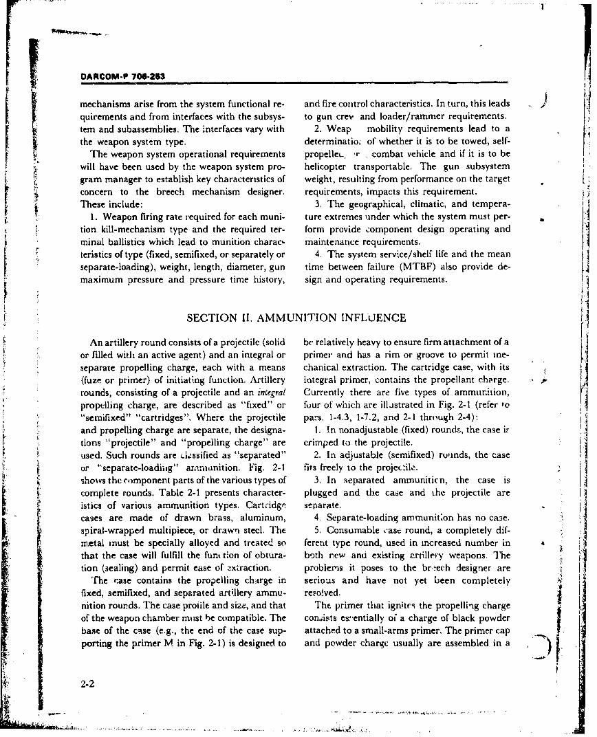
OARCOM-P 706-253
mechanisms arise from the system functional re- and fire control characteristics. In turn, this leads
quirements and from interfaces with the subsys- to gun crev and loader/rammer requirements.
tern and subassemblies. The interfaces vary with 2. Weap mobility requirements lead to a
the weapon system type. determinatiow of whether it is to be towed, self-
The weapon system operational requirements propelleL. ,r combat vehicle and if it is to bewill have been used by the weapon system pro- helicopter transportable. The gun subsystem
L gram manager to establish key characteristics of weight, resulting from performance on the target
concern to the breech mechanism designer. requirements, impacts this requirement.These include: 3. The geographical, climatic, and tempera-
1 1. Weapon firing rate required for each muni- ture extremes under which the system must per-
tion kill-mechanism type and the required ter- form provide component design operating and
minal ballistics which lead to munition charac- maintenance requirements.
teristics of type (fixed, semifixed, or separately or 4. The system service/shelf life and the mean
separate-loading), weight, length, diameter, gun time between failure (MTBF) also provide de-
maximum pressure and pressure time history, sign and operating requirements.
SECTION II. AMMUNITION INFLUENCE
An artillery round consists of a projectile (solid be relatively heavy to ensure firm attachment of a
or filled with an active agent) and an integral or primer and has a rim or groove to permit me-
separate propelling charge, each with a means chanical extraction. The cartridge case, with its
(fuze or primer) of initiating function. Artillery integral primer, contains the propellant charge.
rounds, consisting of a projectile and an iniegral Currently there are five types of ammurition,
propelling charge, are described as "fixed" or fuur of which are illastrated in Fig. 2-1 (refer to"semifixed" "cartridges". Where the projectile pars. 1-4.3, 1-7.2, and 2-1 through 2-4):
and propelling charge are separate, the designa- 1. In nonadjustable (fixed) rounds, the case ir
tions "'projectile" and "propelling charge" are crimped to the projectile.used. Such rounds are 6,ssified as "separated" 2. In adjustable (semifixed) rounds, the case
or '"separate-loadiig" aramimnition. Fig. 2-1 fits freely to the projec:ile. jshows the component parts of the various types of 3. In separated ammuniticn, the case is
complete rounds. Table 2-1 presents character- plugged and the case and the projectile are
istics of various ammunition types. Cartridge separate.
cases are made of drawn brass, aluminum, 4. Separate-loading ammunit~on has no ca3e.spiral-wrapped multipiece, or drawn steel. The 5. Consumable cast round, a completely dif-metal must be specially alloyed and treated so ferent type round, used in increased number in 4L
that the case will fulfill the funt tion of obtura- both rew and existing artillery weapons. Thetion (sealing)and permit ease of extraction. problems it poses to the breech designer are
The case contains the propelling charge in serious and have not yet been completely
fixed, semifixed, and separated artillery ammu- reso!ved.nition rourds. The case profile and size, and that The primer that ignites the propelling charge
of the weapon chamber must be compatible. The consists es'.entially of a charge of black powderbase of the case (e.g., the end of the case sup- attached to a small-arms primer. The primer cap
porting the primer M in Fig. 2-1) is designed to and powder charge usually are assembled in a I2-2
,• • : , l . .. .. . .. . ...... . ,•,: .. . . . .. . .. .= ... . .. . -. . ... . .. .. . . .. :• , ,• L •, , .. ...
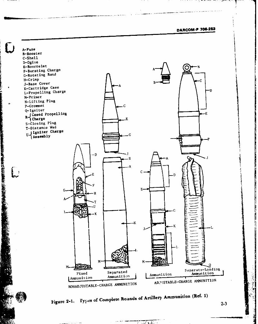
DARCOM-P 700-253
~ A-FuzeB-BoosterC-ShellD-OgiveE-Bourre let NF-Bursting Charge AG-Rotating Band
H-Crimp C
3-Base CoverK-Cartridge Case A
L-Propellilng Charge
M-PrimerN-Lifting PlugP-Grommet .0-Igniter C
"RCased Propelling _ E
RCharge •-E -
S-Closing PlugT-Distance Wad
U1 ignter Charge P
SAssemblY G
S AJ
ED
FG HE
TU
-KIi* K L
•! N , t
M- H -
Fixed Separated separateLoadinFAmunitiox Ammunition i j-mmniti Ammunition
__:_• r ADJSTABE-CARGE AMMUNITION
d NONADJUSTABLE-CHARGE AMMUNITION ADISTABLE.CH AUT
4Figure 2-1. rypc~s of Complete Rounds of Artillery Ammunition (Ref. 1)
2-3
• '. '..•- t & :.
DARCOM-P 706-253
metal tube. When used with a fixed, semifixed, the neck of the case between the charge and pro- , ,
and separated ammunition, this tube is forcefit- jectile base. Fig. 2-2(A) shows this cartridgeted into the base of the cartridge case at the time chambered.of manufacture. In separated ammunition, an The breech mechanism designer must considerauxiliary igniter charge is placed around the the following items with regard to this type ofprimer or on the wadding to insure proper igni- ammunition:tion of the propellant. When sep 3rate-loading 1. Cartridge case shapeammunition is used, the primer is inserted, by 2. Firing pin actuationhand or mechanically, into the firing block or 3. Case extraction
mechanism as the final step in loading. The 4. Case ejectionigniter charge is in a bag sewn to the base end of 5. Ramming velocity (debulleting) in anthe propelling charge. A core through the center automatic loader/rammer.of the propelling charge bag is used sometimes 6. Safety of the loader's hand when closing thefor upper zone charges, in addition to the base breechblock.igniter pad.
Historically, artillery primers have been 2-2 SEMIFIXED AMMUNITIONclassified according to the method by which they In semifixed ammunition, the case fits looselyare fired-i.e., percussion, electric, combination over the projectile, allowing adjustment of thepercussion-electric, and friction. The most com- propelling charge for zone firing. The propellingmon primer in use today is the percussion type. charge is divided into sections, each containing aThe percussion primer, generally used in all ar- bag of propellant powder. The charge is adjustedtillery ammunition, is fired by a blow of the firing by lifting the projectile from the case, removingpin. The primers used in cartridge cases contain the unnecessary sections or increments, and (Asufficient black powder to ignite the propellant in reassembling the case and projectile.the cartridge case. Those used with separate- The breech designer's checklist is nearly theloading propelling charges contain only eoough same as that for fixed ammunition. Debulleting isblack powder to ignite a black powder igniter not a problem since the projectile is stopped bycharge attached to the propelling charge. A com- the rotating band engaging the forcing cone. Ero-plete description of artillery ammunition is sion of the forcing cone can cause changes in theprovided in TM 9-1300-200 (Ref. 3). chamber volume and affect range accuracy, (In
fixed ammunition, it can cause blc'wby.) Extrac-tion of a round that has failed to fire (misfire or2-1 FIXED AMMUNITION hangfire) must be considered-the projectile will
In fixed ammunition, the projectile is per- not easily extract with the case and the designI2'manently fastened to the cartridge case and is must permit rapid clearing of a h-t chamber.loaded into the weapon as a single unit. Thepropelling charge is not adjustable and the round 2-3 SEPARATE-LOADINGbecomes unserviceable if the projectile and case AMMUNITIONbecome loosened or unfastened before firing. The The components of separate-loading ammuni- 1case and projectile usually are crimped rigidly tion, see Fig. 2-2(B), are loaded individuzlly.together with the propelling charge loaded First the projectile is inserted into the breech andloosely or in a plastic bag into the case (Fig. 2-1 rammted. Secondly, the inultisectional propelling(Item L)). When the charge does not completely charge (Fig. 2-3) is placed in the powder cham-fill the case, a spacgr or distance wadding (usu- ber immediately behind the projectile. After the .ally a cardboard &4 and cylinder) is inserted in breecb.block has been closed, and locked behind
2-4
ho 1L, --L, _.V
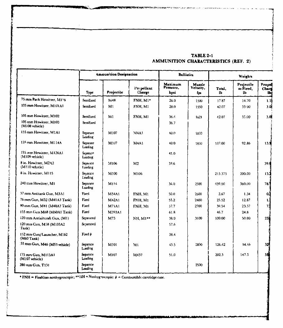
TABLE 2-1AMMUNITION CHARACTERISTICS (REF. 2)
4mmunition Designation Ballistics Weights
Maximum Muzzle Projectile Propel1-r-pell-ai t Pressure, Velocity, Total, as Fired, Charg
Type Projectile Charge kpai fpM lb lb rol75m akHrizr 6 Semnifixed M48 FNH, MI1* 26.0 1500 17.87 14.701.|
105 mm Howitzer, MI01Al Sentifixed MI FNH, MI 28.0 1550 42.07 33 00 3.0•
105 mnm Howitzer, M 102 Semifixed M 1FNH, MI 36.4 1621 42.07 313.00 3.0105 min Howitzer, M 103 Semifixed 36.7(M 108 vehicle)
155 mm Howitzer, MI A Separate M 107 M4A1 40.0 1850Loading
155 mm Howitzer, Mi 14A Separate M107 M4A1 40.0 1850 107.00 92.86 13.•Loading
155 mm Howitzer, M126A1 Separate 41.0!M 109 vehicle) Loading
8 in. Howitzer, M24.2 Sepa.ate M106 M2 39.6 39(MI 10 vehicle) Loading
8 in. lowitzer, MI 15 Separate M\100 M106 213.375 200.00Loading
240 mm Howitzer, Mi Separate Mi 14 36.0 2300 439.00 360.00 78'Loading
37 mm Antitank Gun, M3AI Fixed M54A1 FNH, MI 50.0 2600 2,67 1.34 .76 mrnm Gun, M32 (M41A3 Tank) Fixed M42A1 FNH, MI 55.2 2400 25.52 12.87 190 mm Gun, M41 (M48A3 Tank) Fixed M71A1 FNH, MI 57.7 2700 39.54 23.57 7155mm nGun M68 (M60AI Tank) Fixed M393A1 61.8 46.7 24.8120 mm Antiaircraft Gun, (MI) Separated M73 NH, MI** 38.0 3100 100.00 50.00 2120 mm Gun, M58 (M 103A2 Separated 57.6'ank)
152 mm Gun/Launcher, M162 Fixed # 38.4(M60 Tank)55 mm Gun, M46 (M53 vehicle) Separate MI01 M1 43.5 2800 126.42 W4.69 3
Loading
-15 mrn Gun, M 113A1 Separate M107 M437 51.0 202.3 147.3 5(M 107 vehicle) Loading
280 mm Gun, TI 31 Separate 2500L~oading
• FNH Flashless nonhygroscopic; * NH Nonhyg-os.opic: Combustibl'= cartridge case.
OWmo
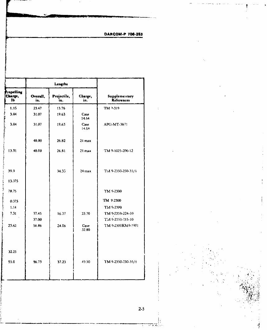
DARCOM-P 706-253
________ ~Lengths _____
ropellingCharge, Overall, Projectile, Charge, Supplementary
lb in. in. in. References
1.15 23.47 13.76 TM 1-319
3.04 31.07 19.63 Case14.64
3.04 31.07 19.63 Case APG-MT-387114.64
48.00 26.82 21 max
13.91 48.C0 26.81 21 max TM 9-1025-200-12
39.9 34.35 24max TM 9-2350-230-35/1
13.375
78.75 TM 9-2300
0.375 TM 9.2300
1.14 TM 9-2300
7.31 37.45 16.37 23.70 TM 9-2350-224-10
37.00 T'A 9-2350-215-10
23.62 56.86 24.06 Case TM 9-2300KM9- 90132.80
32.23
55.0 %.73 37.23 49.50 TM 9-2350-230-15/1I
*1t
2-5
i.,

.[
This page left blank intentionally
-w-MOEWMEM
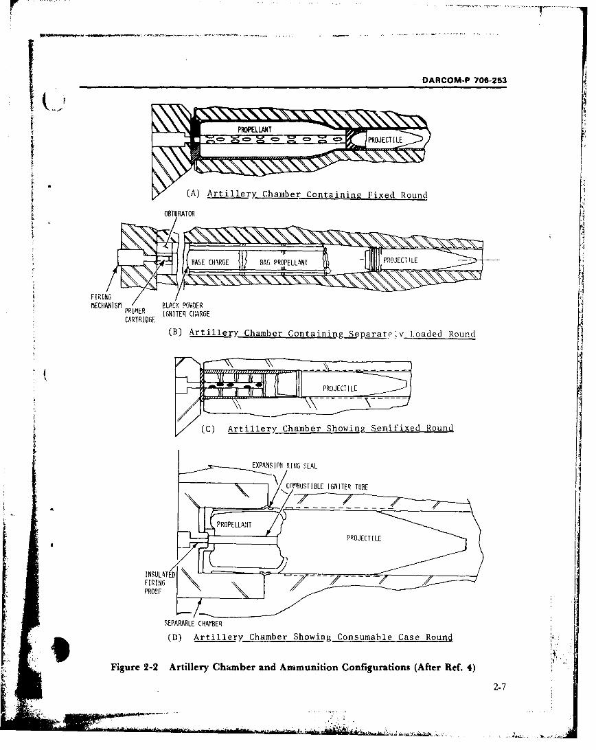
I DARCOM-P 706-253
(A)~m Artiller Chamtber Containinp- Fixed Round
F IR INGMECHANISM BLACK POWDER
PRIMER IGNITER CKARGECARTRIDGE
(B) Artillery. Chamber Containing_ Separatc?;v Loaded Round
(C) Artiller Chamber Showing Sernifixed Round
EXPANSIPflN RING S[AL
CQMBUSTIBLE IGNITER TUBE
PROPE
SEPARABLE CHAMBER9 (D) Artiller Chamber Showing Consumable Case Round
Figure 2-2 Artillery Chkmber and Ammunition Configurations (After Ref. 4)
2-7
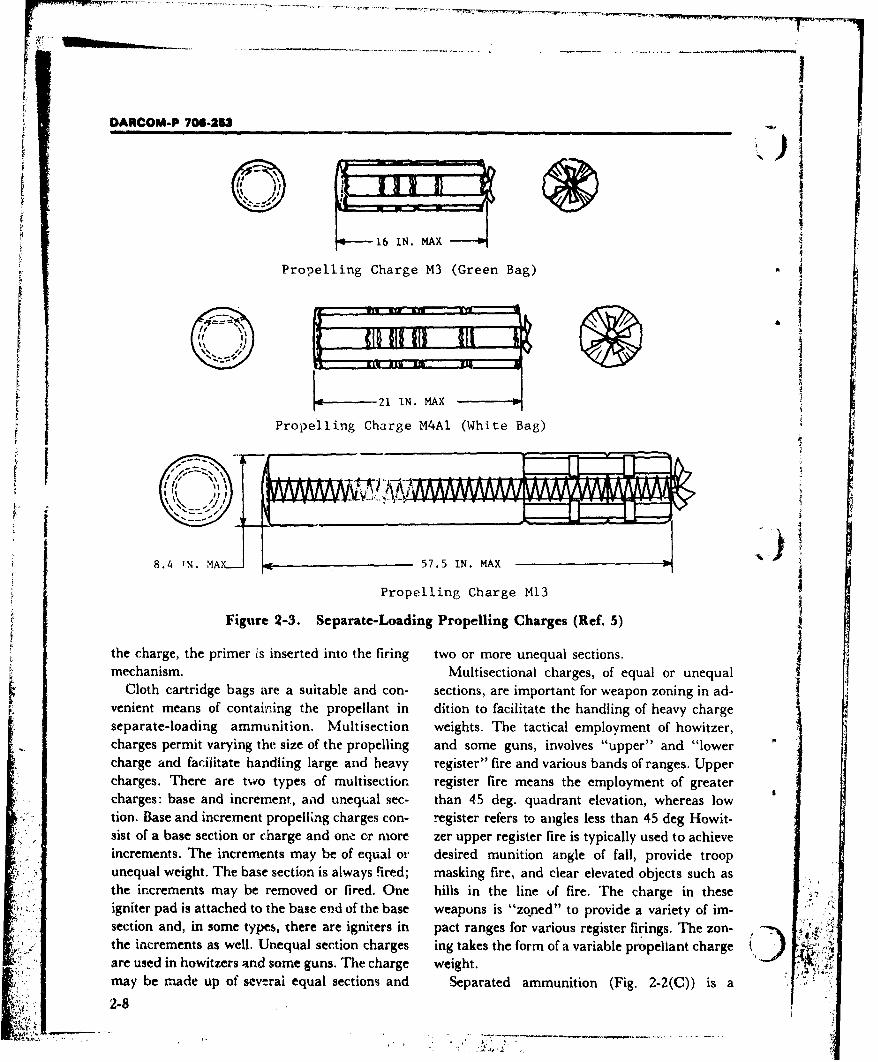
--
DARCOM-P 706.2-3
0 ,,
to i6 IN. MAX
Propelling Charge M3 (Green Bag)
S 21 MAX
Propelling Charge M4AI (White Bag)
8.4 TN. MAX___ 57. 5 IN. MAX
Propelling Charge M13
Figure 2-3. Separate-Loading Propelling Charges (Ref. 5)
the charge, the primer is inserted into the firing two or more unequal sections.mechanism. Multisectional charges, of equal or unequal
Cloth cartridge bags are a suitable and con- sections, are important for weapon zoning in ad-
venient means of containing the propellant in dition to facilitate the handling of heavy chargeseparate-loading ammunition. Multisection weights. The tactical employment of howitzer,charges permit varying the size of the propelling and some guns, involves "upper" and "lowercharge and facilitate handling large and heavy register" fire and various bands of ranges. Uppercharges. 'Mere are two types of multisection. register fire means the employment of greatercharges: base and increment., a~ad unequal sec- than 4.5 deg. quadrant elevation, whereas lowtion. Base and increment propelling charges con- register refers to angles less than 45 deg Howit-gist of a base section or charge and one or more zer upper register fire is typically used to achieveincrements. The increments may be of equal oi- desired munition angle of fall, provide troopunequal weight. The base section is always fired; masking fire, and clear elevated objects such asthe increments may be removed or fired. One hills in the line uf fire. The charge in these :,igni'ter pad is attached to the base epd of the base weapons is "zoned" to provide a variety of im-section and, in some types, there are igniters in pact ranges for various register firings. The zon- .•ithe increments as well. Unequal section charges ing takes the form of a variable propeliant charge "V. ..
are used in howitzers and some guns. The charge weight. i•!"'
may be made up of sew-rai equal sections and Separated ammunition (Fig. 2-2(C)) is a2-8
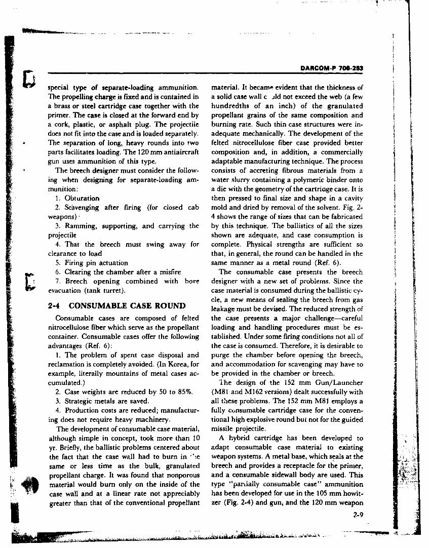
DARCOM-P 706-253,
special type of separate-loading ammunition, material. It becamo- evident that the thickness ofThe propelling charge is fixed and is contained in a solid case wall c .4d not exceed the web (a fewa brass or steel cartridge case together with the hundredths of an inch) of the granulatedprimer. The case is closed at the forward end by propellant grains of the same composition anda cork, plastic, or asphalt plug. The projectile burning rate. Such thin case structures were in-
does not fit into the case and is loaded separately. adequate mechanically. The development of the 'A The separation of long, heavy rounds into two felted nitrocellulose fiber case provided better
parts facilitates loading. The 120 mm antiaircraft composition and, in addition, a commerciallygun uses ammunition of this type. adaptable manufacturing technique. The process
The breech designer must consider the follow- consists of accreting fibrous materials from aing when designing for separate-loading am- water slurry containing a polymeric binder ontomunition: a die with the geometry of the cartriage case. It is
I.- Obturation then pressed to final size and shape in a cavity2. Scavenging after firing (for closed cab mold and dried by removal of the solvent. Fig. 2-
weapons) 4 shows the range of sizes that can be fabricated3. Ramming, supporting, and carrying the by this technique. The ballistics of all the sizes
projectile shown are adequate, and case consumption is4. That the breech must swing away for complete. Physical strengths are sufficient so
clearance to load that, in general, the round can be handled in the5. Firing pin actuation same manner as a metal round (Ref. 6).
S 6. Clearing the chamber after a misfire The consumable case presents the breech7. Breech opening combined with bore designer with a new set of problems. Since the
evacuation (tank turret). case material is consumed during the ballistic cy-cle, a new means of sealing the breech from gas
2-4 CONSUMABLE CASE ROUND leakage must be devised. The reduced strength ofConsumable cases are composed of felted the case presents a major challenge-careful
nitrocellulose fiber which serve as the propellant loading and handling procedures must be es-container. Consumable cases offer the following tablished. Under some firing conditions not all ofadvantages (Ref. 6): the case is consumed. Therefore, it is desirable to
1. The problem of spent case disposal and purge the chamber before opening the breech,reclamation is completely avoided. (In Korea, for and accommodation for scavenging may have toexample, literally mountains of metal cases ac- be provided in the chamber or breech.cumulated.) The design of the 152 mm Gun/Launcher
2. Case weights are reduced by 50 to 85%. (M81 and M 162 versions) dealt successfully with3. Strategic metals are saved, all these problems. The 152 mm M81 employs a4. Production costs are reduced; manufactur- fully ctunsumable cartridge case for the conven-
ing does not require heavy machinery. tional high explosive round but not for the guidedThe development of consumable case material, missile projectile.
although simple in concept, took more than 10 A hybrid cartridge has been developed toyr. Briefly, the ballistic problems centered about adapt consumable case material to existingthe fact that the case wall had to burn in `ie weapon systems. A metal base, which seals at thesame or less time as the bulk, granulated breech and provides a receptacle for the primer,propellant charge. It was found that nonporous and a consumable sidewall body are used. This
4" ' material would burn only on the inside of the type "partially consumable case" ammunitioncase wall and at a linear rate not appreciably has been developed for use in the 105 mm howit-greater than that of the conventional propellant zer (Fig. 2-4) and gun, and the 120 mm weapon
2-9
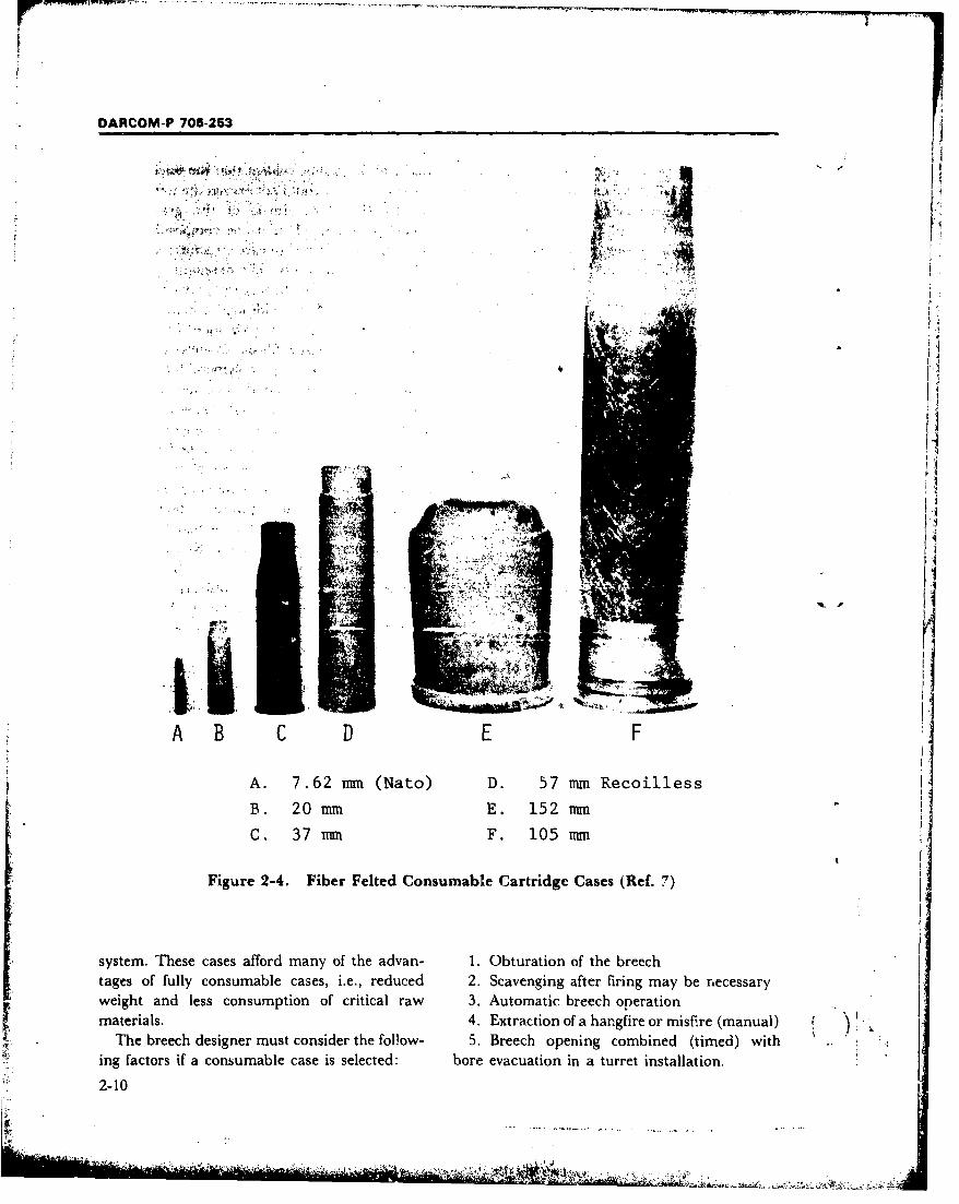
r-w--
DARCOM-P 706-253
S,- . .i HL "
: ;. 5 ," • ' •
ii
A B C D E F
A. 7.62 mm (Nato) D. 57 mm Recoilless
B. 20 mm E. 152 mm
C. 37 mm F. 105 mm
Figure 2-4. Fiber Felted Consumable Cartridge Cases (Ref. 7)
system. These cases afford many of the advan- 1. Obturation of the breechtages of fully consumable cases, i.e., reduced 2. Scavenging after firing may be necessaryweight and less consumption of critical raw 3. Automatic breech operationmaterials. 4. Extraction of a hangfire or misfire (manual)
The breech designer must consider the follow- 5. Breech opening combined (timed) withing factors if a consumable case is selected: bore evacuation in a turret installation.
2-10
yu.
DARCOM-P 706-253
) 2-5 ROCKET-TYPE ROUNDS ignited. The powder gases generated from com-bustion of the conventional charge eject the pro-
Several types of unconventional artillery in jectile from the barrel at a certain muzzlevarious states of design and development use velocity. The reactive charge, which burns dur-rocket motors in some phase of their functional irkg part of the trajectory, creates additional
cycle. The rocket-assisted projectile (RAP) corn- velocity, assuring a significant increase in thebines the properties of conventional (action- range of fire. The rocket-assisted projectile per-
q propelled) and reaction-propelled projectiles. On mits either an increase in the maximum effectiveignition of the conventional (action) powder range with a fixed gun weight or a decrease in thecharge, the delay pellet of the reactive charge is gun weight with a fixed range.
SECTION III. WEAPON INTERFACES
Weapon interfaces were introduced in par. 1-7. is newly designed and not finalized, ear~y dif-
The ammunition interfaces were presented in the ficulties in handling extraction or firing should beprevious section and this section provides similar resolved by the gun designer after discussionsinformation for the tube and chamber bore, with the ballistician and the ammunitionevacuation, recoil system, mount, and fire designer. The chamber volume is designed socontrol. that it is compatible with the propellant density
of loading and, in addition, the chamber interiorshould be shaped to promote the most effective
2-6 TBE AD CH MBERflow of gas frnm chamber to bore[When the ammunition and interior ballistics In US artillery, threads are used to attach the
dlata become available, a chamber and tube that breech firg to the tube. These are usually acme,are sufficiently strong and durable to meet the buttress, or square threads (Fig. 2-45(A)). Theballistic requirements and a breech with dimen- angle of the thread should be small enough tosions that are compatible with the ammunition preclude any reverse rotation which tends tomust be designed. produce unlocking during .firing. A more
The interface between the breech mechanism thorough discussion of thread is provided in par.
Iand chamber (Fig. 2-5) is critical. The chamber 2-27 and analysis is presented in par. 3-17.7. Theis usually considered the rearmost region of the pressure and force acting on the breech aregun tube rather than a component of the breech. described in par. 2-21.One design in which the breech forms part of the The chamber shape for fixed and semnifixedchamber is the separable chamber breech used in ammunition is somewhat more critical than thatthe 152 mmn gun/launcher used for consumable for separate-loading ammunition. Both loadingcase ammunition. Dimensional and concentricity and extracting the cartridge case must be con-tolerances of the chamber must be closely coor- sidered. The chamber slope and clearance aiddinated with the ammunitioa designer to ensure both activities. The clearance between case andadequate fit with the ammunition. chamber should be sufficient for easy loading but
If the gun is to fire existing ammunition, the not large enough to permit excessive plasticchamber must be designed so that there will be deformation or rupture.no problems when loading the round or ex- When a round is fired, propellant gas pressure
S tracting the case-manually or mechanically, expandls the case to the chamber wall. BecauseU hand mode or semiautomatic. If the ammunition the case itself is not strong enough to withstand
Z 2-11
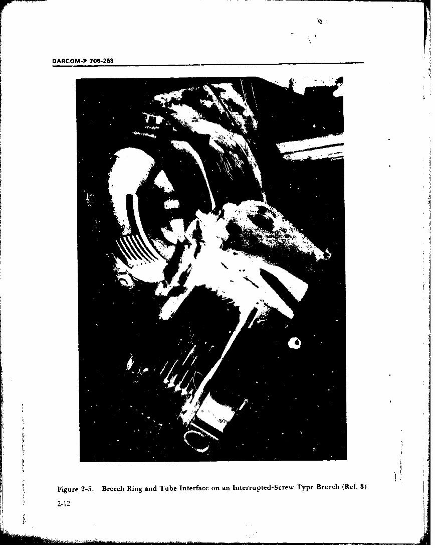
DARCOM-P 706-253
J
Figure 2-5. Breech Ring and Tube Interface on an Inte rru pted -Screw Type Breech (Ref. 3)
2-12
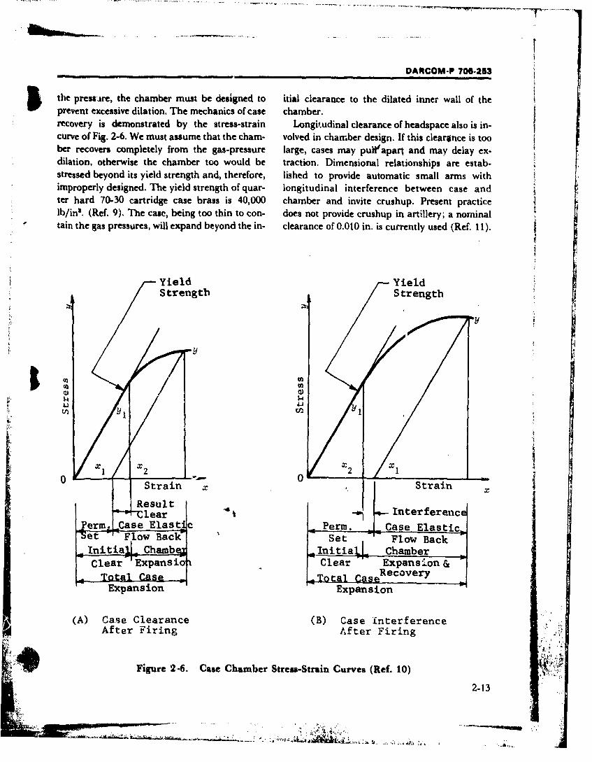
DIARCOM-P 700-263
Fig 2-7 shows the details of a chamber, including jet duration time is increased 25% above thethe longitudinal dimensions to the breech face breech opening time as a precautionary measurewhere the base of the cartridge bears against it. (Ref. 14). If conditions are such that the breechAll pertinent dimensions are shown; most are opening time exceeds the initial fixed jet durationdictated by the size and shape of the case. time, a check valve-type nozzle must be used. A
longer discharge time can be had by using a2-7 BORE EVACUATION AND smaller discharge nozzle or by retaining the dis-
SCAVENGER SYSTEMS charge nozzle and using a larger charging nozzle.
In some weapons installations, notably tank Bore evacuator design procedures are describedand other closed cab or turret type vehicular in more detail in AMCP 706-251 (Ref. 15).mounts, it is necessary to prevent rapid con- A properly designed bore evacuator cantamination of the firing compartment by remove most of the residual gases from the cham-propellant gases that emerge from the bore when ber and bore. The evacuator cannot remove solidthe breech is opened. Some large caliber weapons residue that may remain after consumable casethat use separated ammunition have been equip- ammunition has been fired. A scavenger systemped with a compressed air system that discharges that introduces a jet of air into the chamber hadair through the bore to sweep out residual gases to be designed and developed for this purpose.before the breech is opened. The interface between the operation of the
The need for simpler and less space- scavenger system and the breech mechanism isconsuming system for vehicle installations important. The timing of the jet cycle must be.resulted in the development of the currently used coordinated with the breech-operating cycle, andevacuator (Fig. 2-8). This system uses a cylin- the air supply tubing and manifold must be in-drical jacket fitted around the gun tube near the troduced through the breech.muzzle to form an annular chamber outside thetube and a series of small drilled holes throughthe tube wall slanted toward the muzzle to allow 2-8 RECOIL SYSTEMa restricted flow of gas between the gun bore and The recoil system modifies the loads generatedthe annular chamber. When the projectile passes during firing before transmission to the mountthe holes, a portion of the propellant gas passes (or turret).-Structural strength requirements areinto the evacuator, creating considerable reduced, 4.aý-,ling a more lightweight mountpressure. After the projectile leaves the muzzle, design; aLo, ...he IF y of the gun is better main-the major portion of the gases follow, and the tained by planned dissipation of energy. Mostpressure in the bore drops b.low that in the recoil systems are based upon a single large recoilevacuator chamber. The gas C' nrtent of the cylinder attached, through a lug, to the recoilingevacuator then discharges througki. the drilled gun parts. The interface created between thepassages into the bore, then out the muzzle after breech and the recoil system must accommodatethe breech is open. "t'h(. ",,:igh velocity jet dis- the recoil piston rod end for transmission of bothcharge creates a low ': at the muzzle, in- tensile and compressive loads as experienced inducing a flow of air Lt, ,• 2 : breech and forward the recoil/counterrecoil cycle. In addition, con-through the bore. Size and loc; tion of the sideration should be given to stresses that mayevacuator chamber and pasvaes must be deter. occur as a result of maloperation or rough hand-mined carefully to obtain ef'Tytive flow timed ling such as impact during transportation, aproperly with breech opevin', 4ction. The dis- galled recoil piston, or excessive buffeting forces.charge time must exceed the brme: h opening time Loss of the recoil lug renders the gun inoperativeby a margin sufficient to allow -cane for the in- and requires depot-level service to replace the ,duced air flow to purge the tube effectively. The breech ring. Par. 2-21.2 presents discussion of
2-14
k. i
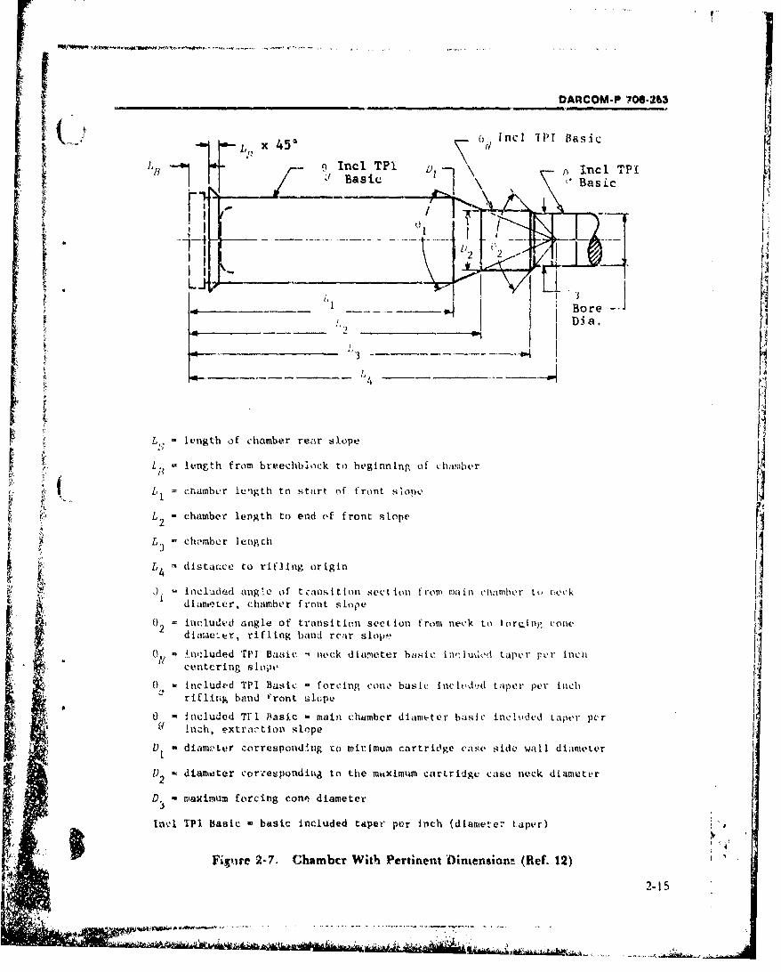
F
_DAnCOM-P 700-263
I ,u , x 45'•c O n ] 11 BasicS n Incl TPI L),n Incl TPI
_____ ,., D.•a.
!..
•. Lq =length of chamber rear slope
F . L[ l e~ngth from br'eechbhiock to heginn ing of chamaberfn
(, L= ch~amber length to stnrt nf front sioue
•k•: L2 - chamber length to end of front slope
~ 2
•: Lg - ch -•mhcr lengch
,j• L dlstai.ce to rifling origin
N•:.• ,). -incl uid ed ang le of tLanlsit ion sect io n from ma min chamber U're, ~ ckL dlaenter, chamber front slope
iludeg d angle of transittin section from neck to bioriing ofchon,2 diLaehm rifleng hand rear slope
a 0I - !n,'luded TPI Basiic -- neck diameter basic i'•,1u dIc' taper per Incndintc ring s 1 orp o
) - included Tanl Basic - forcing ono basic Inc lt'dd t aper per inchd, rifling band r'ront shloeVO - Included T[n Basic - main n hember diameter basic incuided taper per r
n lah, extraction slope
D, diamv.ter corresponding co mirimum cartridge case side wall diameter
1) . diameter corzespondii; to the maximum cartridge case neck diameter2
D3 = maximum forcing cone diameter
Incl TPI Basie basic Included taper per inch (diantete- taper)i '4;pF~re 2-7. Chambcr With Pertinent Oiniensionn (Ref. 12)
2-15
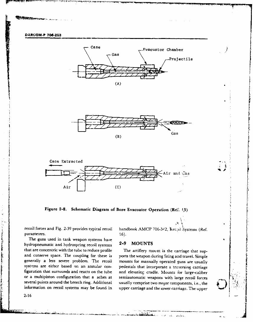
DARCOM-P 706-2G3
Cs .- vacuator Chamber /G -- Gas -\vcatrC
Projectile
(A)P._ _ .. ._ ... . . .. .
IL"
Gas(B)
Case Extracted -
PI1,- • • - Air and 6•as
Air (C)
Figure 2-8. Schematic Diagram of Bore Evacuator Operation (Rep., 1.3) [1/recoil forces and Fig. 2-39 provides typical recoil handbook AMCP 706-342, kec.?il Systems (Ref.
parameters. 16).The guns used in tank weapon systems have
hydropneumatic and hydrospring recoil systems 2-9 MOUNTSthat are concentric with the coupli ng fre the pois rThe weapon in ti carriage that sup-and conserve space. The coupling for these is ports the weapon during firing and travel. Simplegenerally a less severe problem. The recoil mounts for manually operated guns are usuallysyst.ems are either based on an annular con- pedestals that incorporate a trzversing carriagefiguration that surrounds and reacts on the tube and elevating cradle. Mounts for large-caliber , , tor a multipiston configuration that a aches at semiautomatic weapons with large recoil forcesseveral points around the breech ring. Additional usually comprise two major components, i.e., theinformation on recoil systems may be found in upper carriage and the lower carriage. The upper .2-16 j
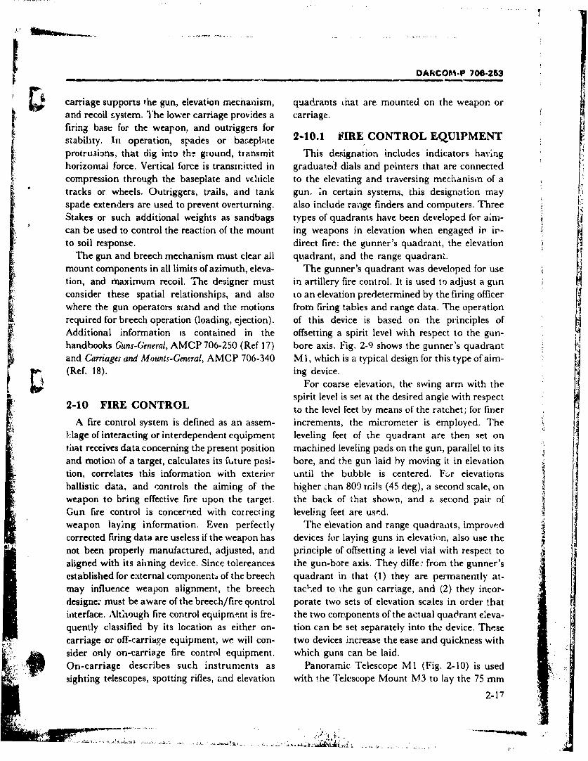
ODANCOM-P 708-253
Scarriage supports the gun, elevation mecnanism, quadrants that are mounted on the weapon orand recoil system. The lower carriage provides a carriage.firing base for the weapon, and outriggers forstability. in operation, spades or ba,-eplate 2-10.1 i'IRE CONTROL EQUIPMENT
protru3ians, that dig into the ground, tiansmit This designation includes indicators havinghorizontal force. Vertical force is transmitted in graduated dials and pointers that are connectedcompression through the baseplate and vehicle to the elevating and traversing mecrhanisin of atracks or wheels. Outriggers, trails, and tank gun. ;n certain systems, this designation mayspade extenders are used to prevent overturning, also include range finders and computers. ThreeStakes or such additional weights as sandbags types of quadrants have been developed for aim-can be used to control the reaction of the mount ing weapons in elevation when engaged in in-to soil response. direct fire: the gunner's quadrant, the elevation
The gun and breech mechanism must clear all quadrant, and the range quadrant.mount components in all limits of azimuth, eleva- The gunner's quadrant was developed for usetion, and maximum recoil. The designer must in artillery fire control. It is used to adjust a gunconsider these spatial relationships, and also to an elevation predetermined by the firing officerwhere the gun operators stand and the motions from firing tables and range data. The operationrequired for breech operation (loading, ejection). of this device is based on the principles ofAdditional information is contained in the offsetting a spirit level with respect to the gun-handbooks Guns-General, AMCP 706-250 (Ref 17) bore axis. Fig. 2-9 shows the gunner's quadrantand Carriages and Mounts-General, AMCP 706-340 M1, which is a typical design for this type of aim-(Ref. 18). ing device.
For coarse elevation, the swing arm with thespirit level is set at the desired angle with respect
2-10 FIRE CONTROL to the level feet by means of the ratchet; for finerA fire control system is defined as an assem- increments, the micrometer is employed. The
LWage of interacting or interdependent equipment leveling feet of the quadrant are then set ontitat receives data concerning the present position machined leveling pads on the gun, parallel to itsand motion of a target, calculates its future posi- bore, and the gun laid by moving it in elevationtion, correlates this information with exterior until the bubble is centered. F;:r elevationsballistic data, and controls the aiming of the higher ..han 809 mils (45 deg), a second scale, onweapon to bring effective fire upon the target. the back of that shown, and a second pair of iiGun fire control is concerned with coireciing leveling feet are used.weapon laying information. Even perfectly The elevation and range quadrants, improvedcorrected firing data are useless if the weapon has devices for laying guns in elevation, also use thenot been properly manufactured, adjusted, and principle of offsetting a level vial with respect toaligned with its ahning device. Since tolereances the gun-bore axis. They differ from the gunner'sestablished for e:xternal componentd of the breech quadrant in that (1) they are permanently at-may influence weapon alignment, the breech tac',ed to the gun carriage, and (2) they incor-designer must be aware of the breech/fire qontrol porate two sets of elevation scales in order thatinterface. Although fire control equipment is fre- the two cormponents of the actual quadrant eleva-quently classified by its location as either on- tion can be set separately into the device. Thesecarriage or off-carriage equipment, we will con- two devices increase the ease and quickness withsider only on-carriage fire control equipment. which guns can be laid.On-carriage describes such instruments as Panoramic Telescope MI (Fig. 2-10) is usedsighting telescopes, spotting rifles, and elevation with the Telescope Mount M3 to lay the 75 mm
2-17
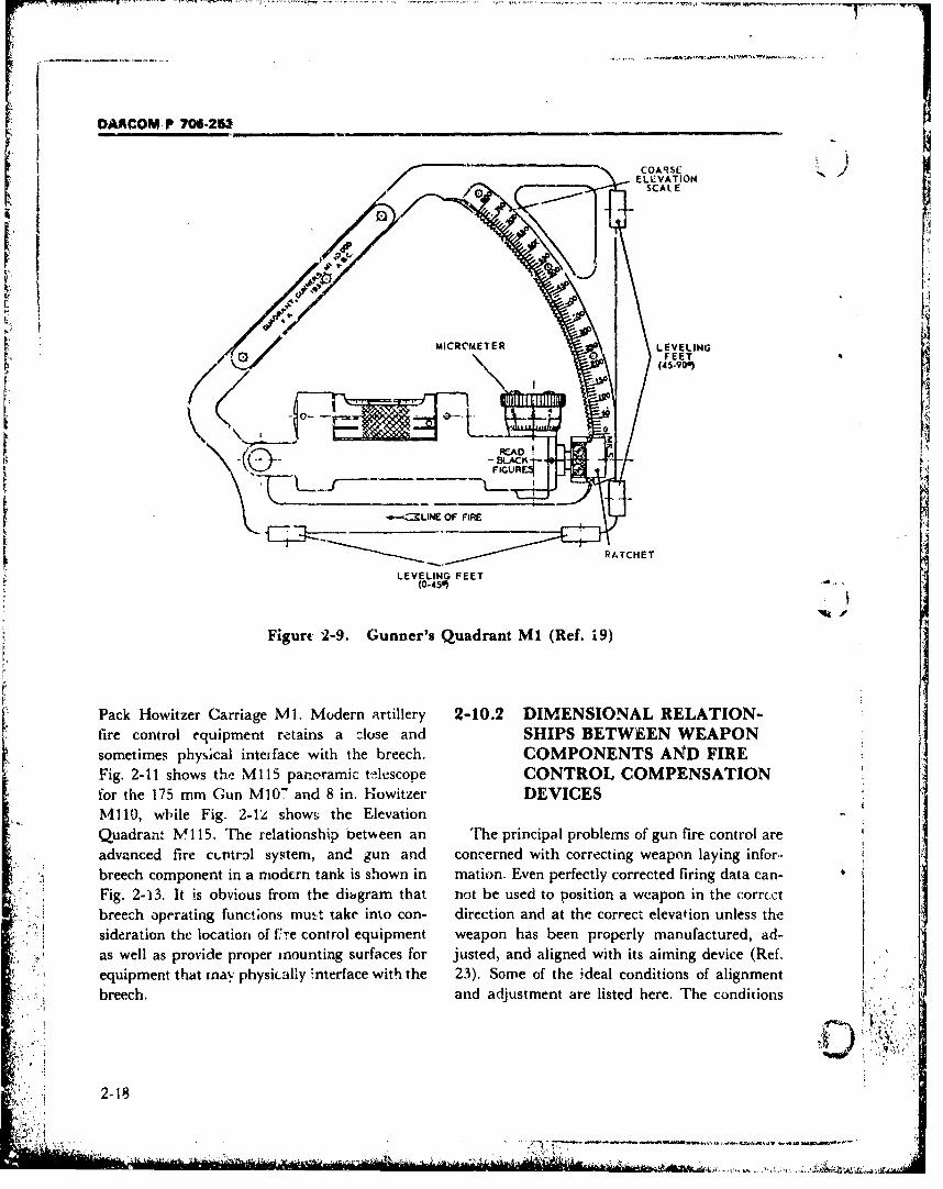
DAR-COM P 70i-25__
ELCVATIONI SCAL E
SMICROMETER LEVELING/ 1FEET 4
I 1I
L t_ ---XLN OF-
""IRATCHETILLEVELING FEET
(0-450)""
Figure 2-9. Gunner's Quadrant M1I (Ref. 19)
Pack Howitzer Carriage MI1. Modern artillery 2-10.2 DIMENSIONAL RELATION-::fire control equipment retains a close and SHIPS BETWEEN WEAPON:isometimes physical interface with the breech. COMPONENTS AND FIRE
SFig. 2-11 shows tht M115 panoramic tthýscope CONTROL COMPENSATION •
Sfor the 175 mm Gun M10" and 8 in. Howitzer DEVICESM110, wh~ile Fig. 2-L4/ show& the Elevation
q. Quadrant M•115. The relationship between an The principal problems of gun fire control areSadvanced fire c(,P~trol system, and gun and concerned with correcting weapon laying infor.-•' .breech component in a niodcrn tank is shown in mation. Even perfectly corrected firing data can-
Fig. 2-13. It is obvious from the dibgram, that not be used to position a weapon in the corr.ctS: I breech operating functions mutt• take into con- direction and at the correct elevation unless the
;e,.. • sideration the location of 177re control equipment weapon has been properly manufactured, ad-•, •, ! as well as provide proper mounting surfaces for justed, and aligned with its aiming device (Ref.,,",',• , equipment that rnay physically interface with the 23). Some of the i,.deal conditions of alignment•:. ..• breech. and adjustment are listed here. The conditions !
..2-18•L,,
2-1AC' -
• •',.•..: ... : -;- -• • .,- . .. .......... .... . .... • . ....GUR
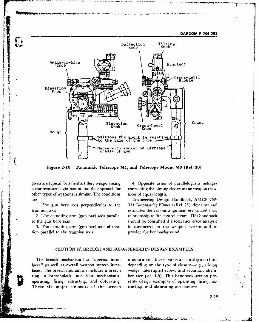
DARCOM-P 706-253
Deflection TiltingKnob Knob
cbi-i-ie- Eyepiece
Cross-LevelS, Bubble
Elevation
Elevation MountKnob Cress--Level< Knob
Mount Ko
Positions the mount n relati [to the axis o the bere
Mates with socket on carriagecradle of gun
Figure 2-10. Panoramic Telcecope Nil, and Telescope Mount M3 (Ref. 20)
given are typical for a field artillery weapon using 4. Opposite arms of parallelogram linkagesa compensated sight mount, but the approach for connecting the aiming device to the weapon trun-other types of weapons is similar. The conditions nion of equal length.are: Engineering Design Handbook, AMCP 760-
1. The gun bore axis perpendicular to the 331 Compensating Elements (Ref. 23), de3cribes andtrunnion axis estimates the various alignment errors arid their
2. 'I'ne actuating arm (gun bar) axis parallel relationship to fire control errors. This handbook1o the gun bore axis should be consulted if a tolerance error analysis
3. The actuating arm (gun bar) axis of rota- is conducted on the weapon system and totion parallel to the trunnion axis provide further background.
SECTION IV. BREECH AND SUBASSEMBLIES DESIGN EXAMPLES
The breech mechanism has "internal inter- mechanism have various configurationsfaces" as well as overall weapon system inter- depending on the type of closure-e.g., slidingfaces. The breecn mechanism includes a breech wedge, interrupted screw, ard separablc chami-ring; a breechblock; and four mechanism.s: ber (see par. 1-5). Thi3 handbook section pre-operating, firing, eAtracting, and obturating. sents design examp!es of operating, firing, ex-These six major elements of the breech tracting, and obturating mechanisms.
2-19
½. . ...... ..
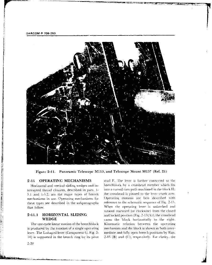
DARCOM-P 706-253
...
Figure 2-11. Panoramic Telescope Mli, and Telescope Mount M137 (Ref. 21)
2-11 OPERATING MECHANISMS stud F. The lever is further connected to the
Horizontal and vertical sliding wedges and in- breechblock by a crosshead member which fitsterrupted thread closures, described in pars. I- into it Curved camn path machined in the block ItI
D.1 and 1-5.2, are the maior types of breech the crosshead is pinned to the lever crank arm.imechanisrns in use. Operating mechanisms for O)perating motions are best described with
these types are described in the subparagraphs reference to the schematic sequence of' Fig. 2-15.
that follow. When the operating lever is unlatched androtated rearward (or clockwise) from the closed
2-11.1 HORIZONTAL SLIDING and locked position (Fig. 2-1 5(A)), the crossheadWEDGE cams the block horizontally to the right.
The one-cycle linear motion of the breechblock Kinematic relation between the operatinu
is produced by Lhe rotation of a single operating mechanismn and the block is shown in both inter-lever. The L-shapcd lever (Component (, Fig. 2- mediate and fully open breech positions by Figs.
14) is supported in the breech ring by its pivot 2-15 (B) and (C), respectively. For clarity, the
2-20
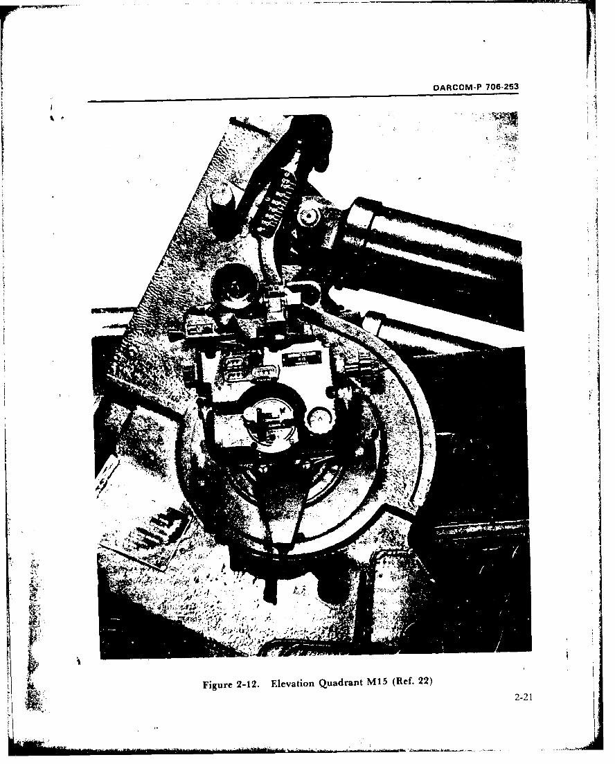
-DARCOM P 706-253
k w"
P"..
Figure 2-12. Elevation Quadrant M15 (Ref. 22)
2-21
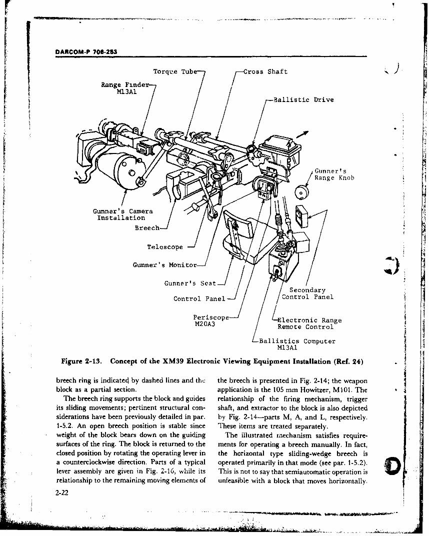
DARCOM-P 706-253
RneFneTorqt'e Tube ross Shaft--- i I IIM.i
Ballistic Drive
Gunner' Gunner's-
_/ VsRange Ko
Guunner's Camet
Control Panel- /Control Panel :
Periscope ltn RangeM20A3 Remote Control P
-- Ballistics Computer ,,!Ml3Al .
Figure 2-13. Concept of the XM39 Electronic Viewing Equipment Installation (Ref. 24)
breech ring is indicated by dashed lines and the the breech is presented in Fig. 2-14; the weaponblock as a partial section. application is the 105 mm Howitzer, M101. The
The breech ring supports the block and guides relationship of the firing mechanism, triggerits sliding movements; pertinent structural con- shaft, and extractor to the block is also depictedsiderations have been previously detailed in par. by Fig. 2-14-parts M, A, and L, respectively.1-5.2. An open breech position is stable since These items are treated separately.weight of the block bears down on the guiding The illustrated mechanism satisfies require-surfaces of the ring. The block is returned to the ments for operating a breech manually. In fact,closed position by rotating the operating lever in the horizontal type sliding-wedge breech isa counterclockwise direction. Parts of a typical operated primarily in that mode (see par. 1-5.2).lever assembly are given in Fig. 2-16, while its This is not to say that semiautomatic operation isrelationship to the remaining moving elements of unfeasible with a block that moves horizontally.
2-22
-A -'.,,
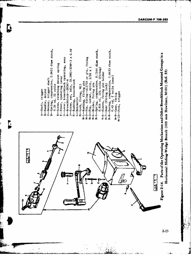
DARCOM.P 706-253
0 0 0
4.4 V.
H IT
C) W ý. 044 -4
w.4 w 0. *0- ýO 0 t
w~ w) I' U u P: *
0-43)r 0H rh L)o n -- ý - J -(a 0 3 W . C'-4 00~ 000mV.0C1 4C C 0 W CL W2f
1- W IH C: 0 04 00 -4
4J~ C34 !¶0 00 U l-
9) (U 0 4- "a .cj W qj 004-w-00 a o ' E U 4) C ~I. to 4e 1.4 W 041 I O . U4 0
m u 0) 14 1 C
4J4 0X. -4 .41ý P 4
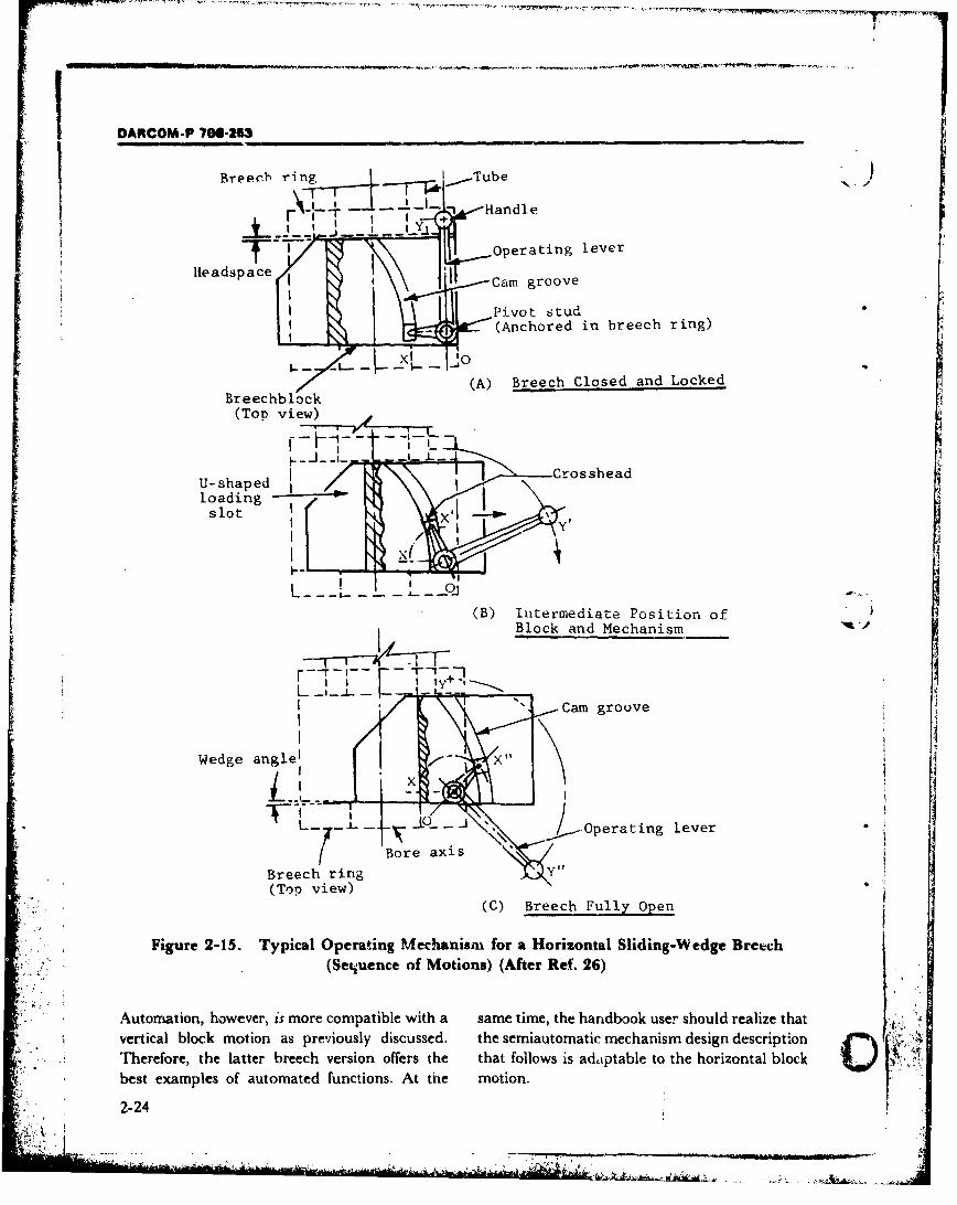
DARCOM-P 706-253
Breeeb ring -- Tube )
~ ~ -HandleI IY_ __ .J-- .• - - _., 1
Operating lever
Hleadspace G Cam groove
Pivot stud- (Anchored in breech ring)
(A) Breech Closed and LockedBreechblock 1
(Top view)
CrossheadU-shaped /--Crloadingslot .
I--
(B) Intermediate Position of
Block and Mechanism
I I it y
I /Cam groove
Wedge angle1
L 4 J(\ -Operating lever
Bore axis
Breech ring y"
(Top view)
(C) Breech Fully Open
Figure 2-15. Typical Operating Mechanism for a Horizontal Sliding-Wedge Brech
(Sequence of Motions) (After Re(. 26)
Automation, however, is more compatible with a same time, the handbook user should realize that
vertical block motion as previously discussed. the semiautomatic mechanism design description 0 .
Therefore, the latter breech version offers the that follows is adaptable to the horizontal blockbest examples of automated functions. At the motion.
2-24
'4-'- 'V ;
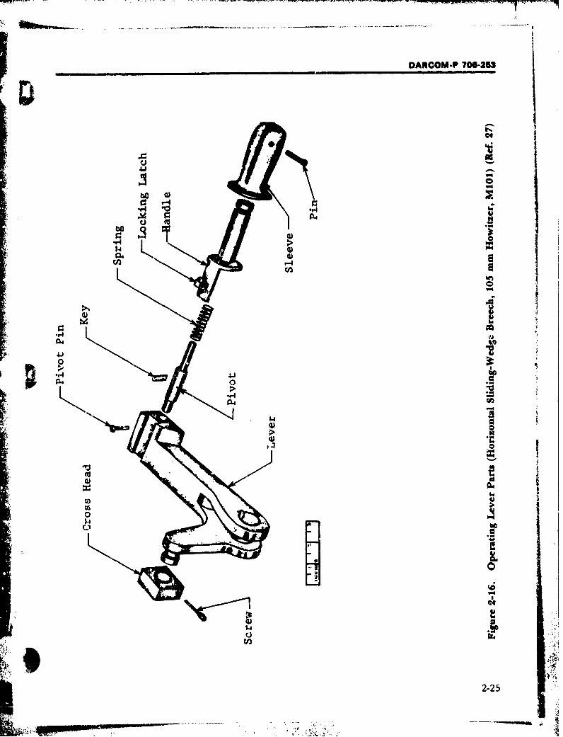
DARCOMPF 706-253
V44
C) 0"4 >
040
.1-I *~ *r
t 04
04a
0 04
*1-4
044
2-2
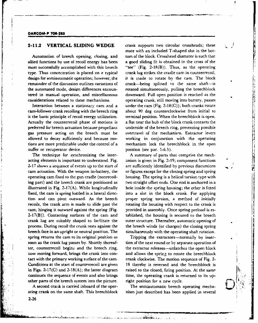
DARCOM-P 706-253
2-11.2 VERTICAL SLIDING WEDGE crank supports two circular crossheads; these /mate with an included T-shaped slot in the bot-
Automation of breech opening, closing, and tom of the block. Crosshead diameter is such thatallied functions by use of recoil energy has been a good sliding fit is obtained in the cross of themost successfully accomplished with this breech "tee" (Fig. 2-18(B)). Thus, as the operatingtype. Thus concentration is placed on a typical crank lug strikes the cradle cam in counterrecoil,design for semiautomatic operation; however, the it is made to rotate by the cam. The blockremainder of the discussion outlines variations of crank--being splined to the samre shaft--isthe automated mode, design differences encoun- rotated simultaneously, pulling the breechblock
tered in manual operation, and miscellaneous downward. Full open position is reached as theconsiderations related to these mechanisms. operating crank, still moving into battery, passes
Interaction between a stationary cam and a under the cam (Fig. 2-18(C)); both cranks rotatecam-follower crank recoiling with the breech ring about 90 deg counterclockwise from initial tois the basic principle of recoil energy utilization, terminal position. When the breechblock is open,Actually the counterrecoil phase of motions is a flat near the hub of the block crank contacts thepreferred for breech actuation because propellant underside of the breech ring, preventing possiblegas pressure acting on the breech must be overtravel of the mechanismn. Extractor leversallowed to decay sufficiently and because mo- working in conjunction with the operatingtions are more predictable under the control of a mechanism lock the breechblock in the openouffer or recuperator device, position (see par. 1-6.5).
The technique for synchronizing the inter- A summary of parts that comprise the mech-acting elements is important to understand. Fig. anism is given in Fig. 2-19; component functions -
2-17 shows a sequence of events up to the start of are sufficiently identified by previous discussions .
cam actuation. With the weapon in-battery, the or figures except for the closing spring and springoperating cam fixed to the gun cradle (nonrecoil- housing. The spring is a helical torsion type withing part) and the breech crank are positioned as two straight offset ends. One end is anchored in aillustrated in Fig. 2-17(A). While longitudinally hole inside the spring housing; the other is fittedfixed, the cam is spring loaded in a lateral direc- into a slot in the block crank. For applyingtion and can pivot outward. As the breech proper spring torsion, a method of initiallyrecoils, the crank arm is made to slide past the rotating the housing with respect to the crank iscam, hinging it outward against the spring (Fig. provided in assembly. Once spring preload is es-2-17(B)). Contacting surfaces of the cam and tablished, the housing is secured to the breechcrank lug are suitably shaped to facilitate the outer structure. Thereafter, automatic opening ofprocess. During recoil the crank rests against the the breech winds (or charges) the closing springbreech face in an upright or neutral position. The simultaneously with the operating shaft rotation.spring returns the cam to its original position as Tripping the extractors-normally by inser-soon as the crank lug passes by. Shortly thereaf- tion of the next round or by separate operation ofter, counterrecoil begins and the breech ring, the extractor releases-unlatches the open blocknow moving forward, brings the crank into con- and allows the spring to rotate the breechblocktact with the primary working surface of the cam. crank clockwise. The motion sequence of Fig. 2-Conditions at the start of counterrecoil are given 18 thereby is reversed and the breechblock isin Figs. 2-17(C) and 2-18(A); the latter diagram raised to the closed, firing position. At the same,continues the sequence of events and also brings time, the operating crank is returned to its up-other parts of the breech system into the picture. right position for a new cycle.
A second crank is carried inboard of the oper- The semiautomatic breech operating mecha- 'C)ating crank on the same shaft. This breechblock nism just described has been applied in several
2-26
DARCOM-P 706-253
i Outsidc of Cradle - Top View
S " .. Shaped sliding surface
Spring loaded, pivoted breechoperating cam, fixed to cradle
Breech operating shaft
BreechSide Viewof Gun -
Neutral position
, - of operating crank
Primary cam surface Pivot shaft
(A) Operating Cam and Crank Geometry *
(Weapon in Battery) A
rI' Cam displaced laterally -Top view
Sliding surfaces in contact
Crank (Recoiling part)Recoil direction
(B) Cam and Crank Geometry(Weapon in Recoil)
Cam returned to
working position Cradle top view
Breech End
of Gun _ _
. Side view
Terminal position of (breech operating crank,
Breech operating camCounterrecoil direction
(C) Cam and Crank Geometry(Weapon in Counterrecoil)
Figure 2-17. Kinematic Sequence Leading to Engagement of the Operating Cam by theBreech Operating Crank-Breech Actuation via Recoil Energy
2-27
* * , .,. - ,U.
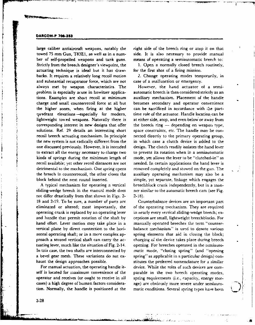
DARCOM-P 706-253
large caliber antiaircraft weapons, notably the right side of the breech ring or atop it on thattowed 75 min Gun, T83E 1, as well as in a num- side. It is also necessary to provide manualber of self-propelled weapons and tank guns. means of operating a semiautomatic breech to:
Strictly from the breech designer's viewpoint, the 1. Open a normally closed breech routinely,actuating technique is ideal but it has draw- foe the first shot of a firing mission,backs. It requires a relatively long recoil motion 2. Change operating modes temporarily, inand substantial recuperator force, which are not case of a malfunction or emergency.always met by weapon characteristics. The However, the hand actuator of a semi-problem is especially acute in howitzer applica- automatic breech is then considered strictly as an
tin.Examples are shoet recoil at minimum auxiliary mechanism. Placement of the handle
tehigher zones, when firing at the higher can be sacrificed in accordance with Uie part-quasdrant elevations -especially for modern, time role of the actuator. Handle location can belightweight tow-ed weapons. Naturally there is at either side, atop, and even below or away fromcorresponding interest in new designs that offer the breech ring - depending on weapon type,solutions. Ref. 29 details an interesting short space constraints, etc. The handle may be con-recoil breech actuatin~g mechanism. In principle nected directly to the primary operating group,the new system is not radically different from the in which case a clutch device is added to theone discussed previously. However, it is intended design. The clutch readily isolates the hand leverto extract all the energy necessary to charge two to prevent its rotation when in a semiautomatickinds of springs during the minimum length of mode, yet allows the lever to be "clutched-in" asrecoil available; yet other recoil distances are not needed. In certain applications the hand lever isdetrimental to the mechanism. One spring opens removed completely and stowed on the gun. Thethe breech in counterrecoil, the other closes the auxiliary operating mechanism may also be ablock behind the next round inserted, simple, yet separate, linkage which engages the
A typical mechanism for operating a vertical breechblock crank independently, but in a mran-sliding-wedge breech in the rnanual mode doves ner similar to the automatic breech cam (see Fig.not differ drastically from that shown in Figs. 2- 2-18).18 and 2-19. To be sure, a number of parts are Counterbalance devices are an important parteliminated or altered; most importantly, the of the operating mechanism. They are requiredoperating crank is replaced by an operating lever in nearly every vertical sliding-wedge breech; ex-and handle that permit rotation of the shaft by ceptions are small, lightweight breechblocks. Forhand effort. Lever motion may take place in a manually operated breeches the term "counter-vertical plane by direct connection to the hori- balance mnechanism" is ustd to denote variouszontal operating shaft; or in a more complex ap- spring elements that aid in. closing the block;proach a second vertical shaft can carry the ac- charging oi^ the device takes place during breechtuating lever, much like the situation of Fig. 2-14. opening. For breeches operated in the semiauto-In tnis case, the two shafts are interconnected by mnatic mode, "closing spring" (and "openinga bevel gear mesh. These variations do not ex- spring" as applicable in a particular design) con-haust the design approaches possible. stitutes the preferred nomenclature for a similar
For manual actuation, the operating handle it- device. While the roles of such devices are com-self is located for mnaximumn convenience of the parable in the two breech operating modes,operator and receives (or ought to receive in all spring requirements (i.e., capacity, energy stor-cases) a high degree of human factors considera- age) are obviously more severe under semiauto-tion. Normally, the handle is positioned at the matic conditions. Several spring types hav'e been )2-28
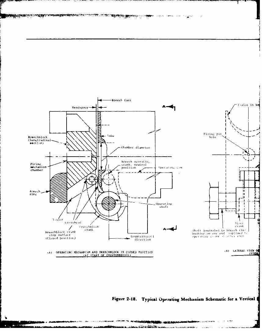
.1
-Breech face
Headspace--i. - A 4 [-tot in
II
- II \~.--
I ub Firinp(' pin
Breechblock hhft
/onit di---.
breech otcvratii S.
Firing Lak1CLrmechanism Lr d( ' Jicun rp. Ichamber -
6d-eechring.
J1 Ib
c. r a n k A M~ ',h .l l' t ý ,,Li r'l . fl vd L , , h t e~''t h ! i 1I 'br ee chb lock ,:r .,n P bushifw t1 o l". I.11 . ,
:.top surfaice Cbu..r tc):It•h''l onl ,n:tk it , ' Ih n ''ji
(Closed posit i,ot.) Codire.ct ion
iA) OPERATING I*.CHANISM AND [OKEECHBLOCK IN CLOSED POSII"II; kK) LATERAL VIEW
(Ar SýTART OF COUINTtiRRECOI,) (VI
Figure 2-18. Typical Operating Mechanism Schematic for a Vertical
-" .- - - -- - - -•~" ,-., • ,••'•i *' M . . . .. .... ,<,....*.- .~i-....... - .. ...11 IQ to .
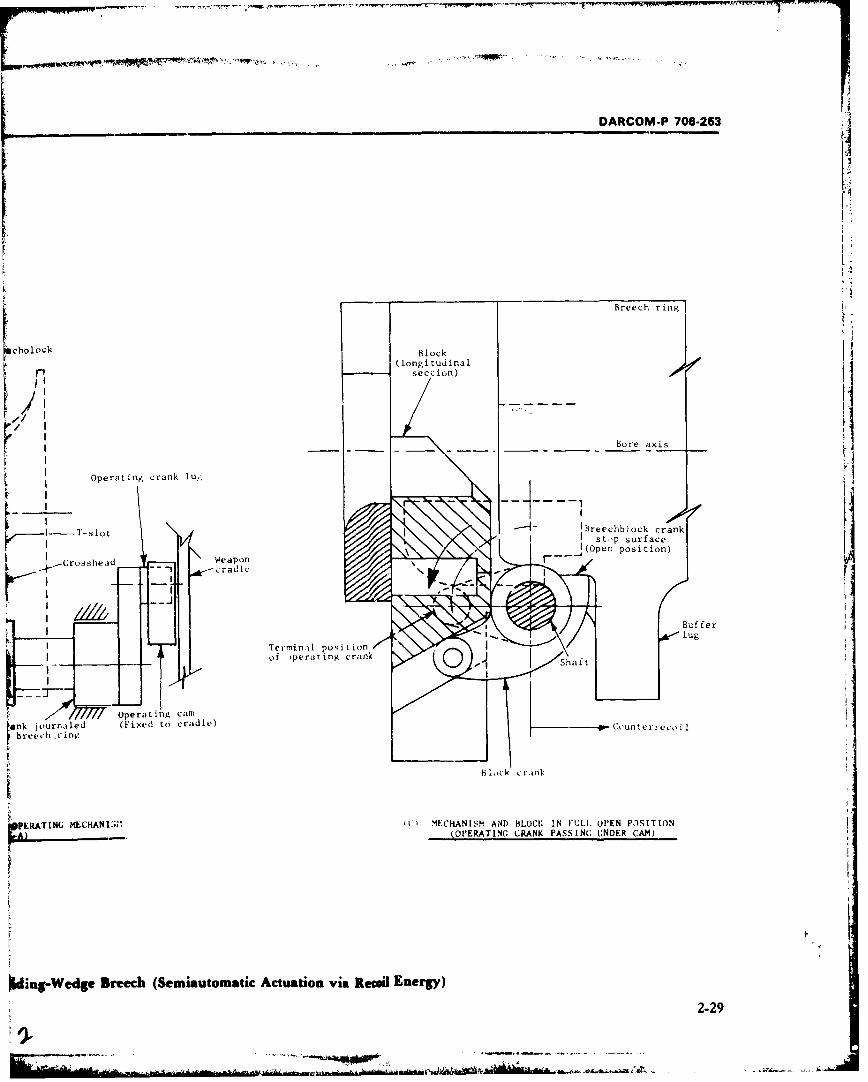
'"PAP
DARCOM-P 706-253
I
Breech ring
,oh0 ock Block i(longitudinal
' ': '" i!
Bore axis
Operating crank lu,;
.'-o _.--- IBreechb)ock crank
S I o t I St,,p surface'I aeapo IJ(Open position)
C -lrosshead rWeapond-i
BufferI lug
I Terrninril position
S 7= -Operating catnrank journaled (Fixed to cradle) (-Counterr-.,coil
breech rinn,.
Block : rank
vPEKATING MECHANISI MECHANISM AND BLOCK IN FULL OPEN POSITION
-- A) OPERATING CRANK PASSING UNDER CAM)
I..
Wding-Wedge Breech (Semiautomatic Actuation via Recoi Energy)
2-294
DARCOM-P 708-253
L 4 CROSSHEADS
rI~~ CLOSINGSPRING CLOSING
SPRINGHOUSIN•G
RETAININGCAP
OPERATING OPERATING
CRANKSHAFT, ASSY
BREECHBLOCKCRANK, ASSY
i a , ,, , • i
r Figure 2-19. Parts of Semiautomatic Breech Operating Mechanism (75 mm Antiaircraft Gun,
T83E1, Vertical Sliding-Wedge Breech) (Ref. 28)
designed into counterbalance or closing devices. 2-11.3 INTERRUPTED SCREW
The helical compression spring was used exten-sively through the World War II era. This The two distinct motions of this closure type
mechanism was quite similar to the one still in take place on separate rotary and hinge axes butuse for interrupted-screw breeches (see Fig. 2- are accomplished by the actuation of one
22), except for the breechblock connecting crankshaft. With the breech in the Jocked posi-
method. Springs oriented both parallel to the tion (Fig. 2-20(A)), a rearward and downward
block motion and parallel to the gun tube were pull on the operating lever (after it has been un-employed. Weight and space requirements have latched) rotates the crankshaft about the x-axis.
made the compression spring element generally A crank on the end of the shaft actuates a cross-
obsolete for this breech type. head that slides in a recess in the breechblockHelical torsion springs represent more efficient and at the same time causes the block to rotate in
space usage in extracting elastic energy. a counterclockwise direction. This limited rota-Although not at all new, this spring type is seeing tion disengages the sectored-threads, of the
renewed emphasis in breech operating closure, unlocking the breech as the first half of a
mechanism design. In the quest for still greater two-cycle motion is accomplished (Fig. 2-20(B)).
energy/vulume efficiency, other spring element Component breakdown of a typical crank-versions are being sought. The torsion leaf spring shaft and operating lever group is provided in
pe-ck or laminated torsion bar is one such Fig. 2-21. This subassembly is supported in theC noteworthy candidate. Developments concerning breechblock carrier by the journal bearing corn-
this interesting breech closing spring type can be ponent shown in the figure. The carrier, which infound in Refs. 30 and 31. turn is anchored to the breech ring, also supports
2-31
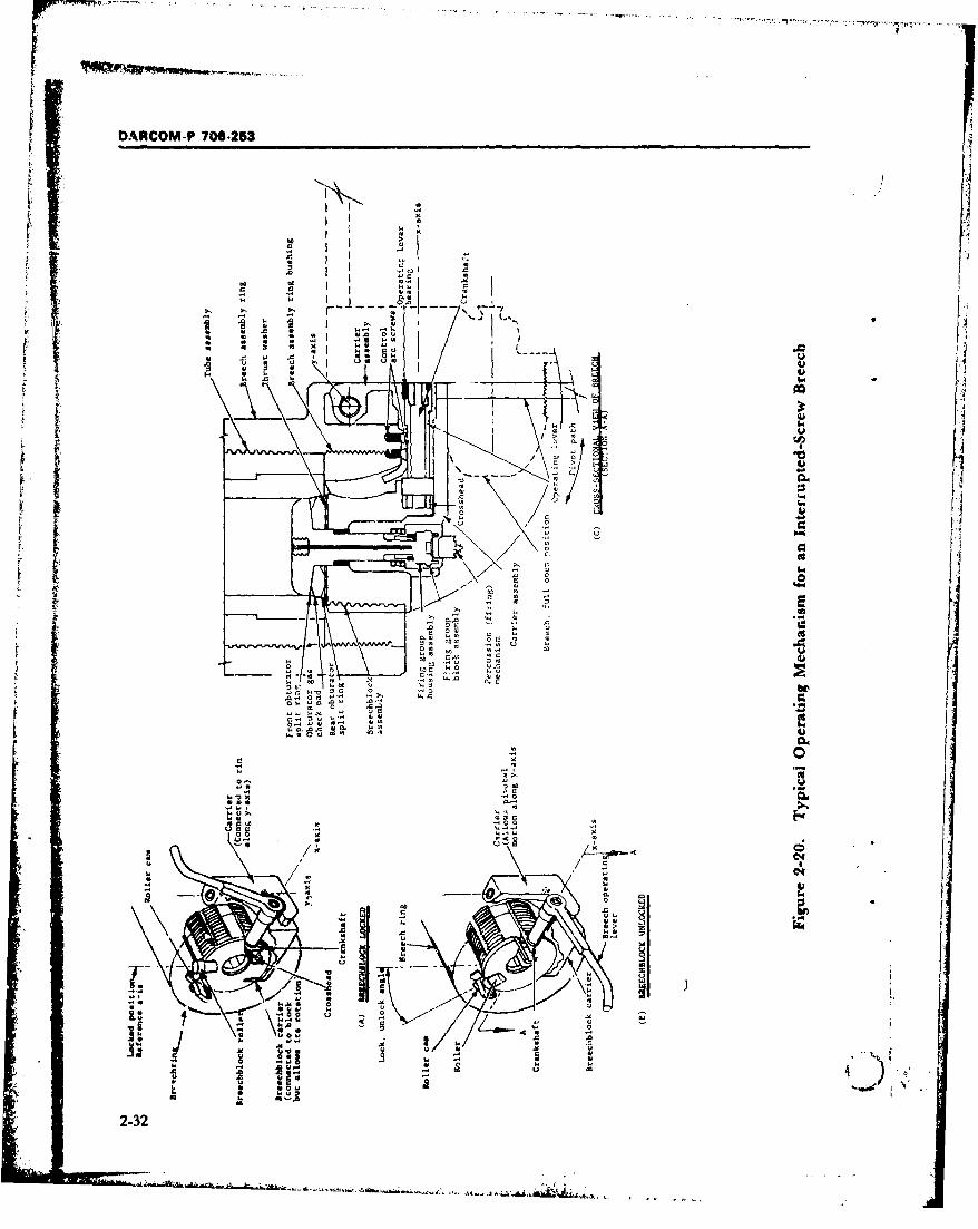
fD�ACOM-P 706-253
t 0
.44,31 .0
.0 .ao
S
00 00 I
0.-IIl�.
ON
-
0 " �
0
..-- �-'(4
.0 .� I
-'
S
01 � .0
.41.
I; I i -4�
�.J
AU
4.)
*.1 (4
0I-
�
U
� 9
I, 0 .0.-I1.�
4.11.1.444
44.10044
N>.
000
�00.1
4.1� 0
00
01010
c�.
44
U
44..
4.10 0
tJ��
. -
r I
0
4.1
e.4
N
-I
�1
40
*
44
-,
'*,4 4;
U
0
4..
0�
--
0.
.0
.0
04>.44
00
"�1�� -
---
A
-.---- '-�'-�
-.---
tat
5
-0
/ N
44
-. I
.4 .01
-
� �0�0 -..0 .0
4. .4-4
.0
.44 *-4 .5
4.a4 0 01
a.
-
*6
.0
40
U .0
i�
-
0 U 01
1.
-.. d 'I
U a2-32
4. .�
... a J... 4..., .4 � � � 4
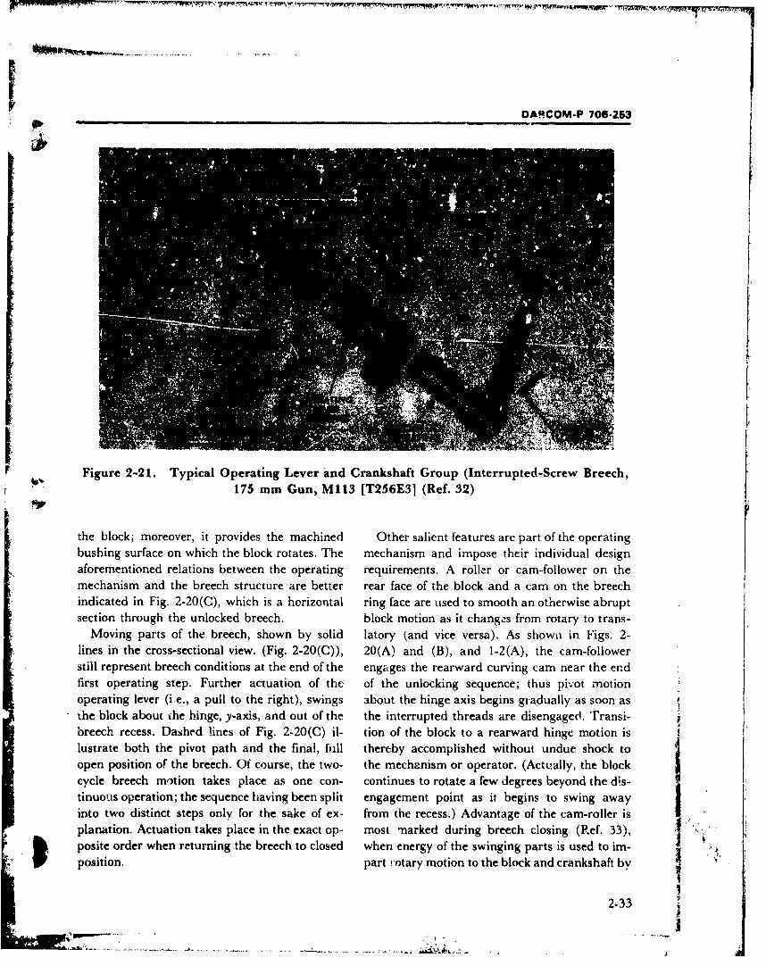
DARCOM-P 706-253
Figure 2-21. Typical Operating Lever and Crankshaft Group (Interrupted-Screw Breech,175 mm Gun, M113 [T256E3] (Ref. 32)
the block; moreover, it provides the machined Other salient features are part of the operatingbushing surface on which the block rotates. The mechanism and impose their individual designaforementioned relations between the operating requirements. A roller or cam-follower on themechanism and the breech structure are better rear face of the block and a cam on the breechindicated in Fig. 2-20(C), which is a horizontal ring face are used to smooth an otherwise abruptsection through the unlocked breech. block motion as it changes from rotary to trans-
Moving parts of the breech, shown by solid latory (and vice versa). As shown in Figs. 2-lines in the cross-sectional view. (Fig. 2-20(C)), 20(A) and (B), and 1-2(A), the cam-followerstill represent breech conditions at the end of the engages the rearward curving cam near the endfirst operating step. Further actuation of the of the unlocking sequence; thus pivot motionoperating lever (i.e., a pull to the right), swings about the hinge axis begins gradually as soon asthe block about the hinge, y-axis, and out of the the interrupted threads are disengaged. Transi-breech recess. Dashed lines of Fig. 2-20(C) il- tion of the block to a rearward hinge motion islustrate both the pivot path and the final, full thereby accomplished without undue shock toopen position of the breech. Of course, the two- the mechznism or operator. (Actually, the blockcycle breech m,'tion takes place as one con- continues to rotate a few degrees beyond the d.s-tinuous operation; the sequence having been split engagement point as it begins to swing awayinto two distinct steps only for the sake of ex- from the recess.) Advantage of the cam-roller is ,planation. Actuation takes place in the exact op- most marked during breech closing (Ref. 33),posite order when returning the breech to closed when energy of the swinging parts is used to im- Y "position. part !otary motion to the block and crankshaft by
2-33
1'1
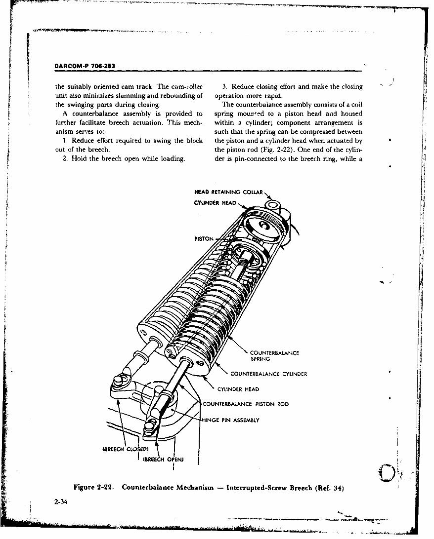
DARCOM-P 706-253
the suitably oriented cam track. The cam-roller 3. Reduce closing effort and make the closingunit also minimizes slamming and rebounding of operation more rapid.the swinging parts during closing. The counterbalance assembly consists of a coil
A counterbalance assembly is provided to spring mounted to a piston head and housedfurther facilitate breech actuation. This mech- within a cylinder; component arrangement isanism serves to: such that the spring can be compressed between
1. Reduce effort required to swing the block the piston and a cylinder head when actuated byout of the breech. the piston rod (Fig. 2-22). One end of the cylin-
2. Hold the breech open while loading. der is pin-connected to the breech ring, while a
HEAD RETAINING COLLARS~CYLINDER HEAD ,
PISTON
•/• COU NTERBALANCESPRING
• COUNTERBALANCE CYLINDER
S• CYLINDER HEAD
•,' • COUNTERBAL.ANCE PISTON ROD
•;: '• "HINGE PIN ASSEMBLY
ISREECH CLOSED)
( (BREECH OPENJ
Figure 2-22. Counterbalance Mechanism - Interrupted-Screw Breech (Ref. 34)
2-34
DARCOM-P 706-253
similar connection is made between the piston This 155 mm Howitzer, M126A1, operatingrod and hinge pin crank arm at the other end of echanism depends on the action of a stationarythe mechanism. (To establish proper geometric cam (located on the weapon mount) against aperspective, the hinge pin axis coincides with the cam-follower crank moving with the breech iny-axis in Fig. 2-20. counterrecoil. Thus far, the basic actuating
As the breech is opened, rotation of the hinge arrangement is very similar to the more corn-pin arm takes place, drawing the piston rearward monly applied sliding-wedge breech version,and thus compressing the spring. Maximum previously described. The handbook user should
ispring compression occurs as the pin passes dead refer to that discussion (par. 2-11.2 and Fig. 2-
center, just before the breech is swung fully open. 17) for the manner of synchronizing the cam andThe toggling effect of the crank allows the spring cam-follower during recoil motion--preparatoryto decompress slightly, and the spring under to their working contact. Beyond this point,Scompression exerts its force on the hinge pin design of the interrupted-screw breech actuatorcrank to hold the breech open. In closing, the takes a radical departure:F spring is compressed again until the crank passes 1. Camming of the operating crank in coun-over dead center; then the counterbalance spring terrecoil, rotates a gear sector on the operatingexerts its force on the crank to close the breech shaft. The sector, being in mesh with a verticallyrapidly. Extreme motions of the assist mech- oriented breechblock operating rack, forces theanism are indicated in Fig. 2-22. A threaded joint rack downward. The rack, which in turn meshesusually connects the piston to the rod, permitting radially with the block, to the left of its axis,a change in spring preload. This may be required causes the block to rotate counterclockwise tofor general adjustment or to increase counter- disengage the sectored closure threads. Blockbalance force--e.g., the closing of the breech at a closing helical springs are charged during thehigher quadrant angle. downward movement of the rack. With the block
A more complete breakdown of mobile parts of open and threads disengaged, the bottom of thean interrupted-screw breech is presented in Fig. rack contacts the carrier housing and the contin-2-23. This figure provides an overview of the ued rotation of the crank rotates the housing to
operating mechanism considerations given and a the breech-open position. During crank rotation,useful correlation with Fig. 2-20. It also es- torsion leaf springs-mounted inside the crank 4
tablishes geometric relations with other assem- and along the crank axis-are wound up. Theblies or components treated elsewhere in the breech is retained in the open or loading positionchapter-namely, the latching mechanism, con- by means external to the cannon, i.e., the operat-trol arc, firing mechanism, and obturator ing crank roller is engaged in the operating camassembly. located on the mount.
The interrupted-screw breech operating mech- 2. Breech closing is accomplished by liftinganism discussed thus far is designed for manual the cam clear of the crank roller (Ref. 36). Whenactuation. As previously outlined, special design the crank Js released, the fully wound returnproblems are encountered in automating breech springs pivot the breechblock and carrier back tofunctions for this closure type. Further coverage the breech recess. The carrier latches snap intoof mechanisms is devoted to the semiautomatic place as the breech ring and block come intomode of breech operation. The citable weapon mesh. Then, the rack closing springs lift theapplication is the 155 mm Self-propelled Howit- breechblock operating rack and thereby rotatezer, M126A1 (M109 Vehicle). This example is the block clockwise into thread engagement. Anall the more noteworthy since recoil energy of the auxiliary operating handle is also part of thecannon is used both for rotary and pivot move- mechanism; it is "clutched-in", when required,ments of the breechblock. to perform the preceding actuations by hand.
2-35
DARCOM-P 706-253
Y-axis
A x-axis
D EH
NOTE: Axes refer to Fig. 2-20 F G ell
F1 - AK JIBA XRCO
G- L-
HKFI 8 MB-
/ -OR--Tp, N P QS- T S
F EE DD CC B3eA
A - HINGE PIN V -FIRING PIN RETAINER8 - OILACUP W - KNOBC - COUNTERBALANCE PISTON ROD END PIN X - FIRING GROUP BLOCKD - HINGE PIN KEY Y - SPRING KE - COTTER PIN - BLOCK FOLLOWERF - LATCHRKjAOR AA - EXTRACTORG - LATCH &B - BREECHOLOCK CARRIERH- OPERATING LEVER ASSEMBLY CC - HIRUST WASHERJ -LATCH SPRING DD - CRC5SHEADK - CRANK EF - BRIEECHOLOCKL. - LATCH BRACKET FF - COTURATOR SPINDL17 ASSEMBLYM - RETAINER iA t:G - SPINDLE KEYN - SPINDLE SPRING HH - ROLLER
41 P : EXTRACTOR PIN JJ - PIVOT PINQ* FIRING MECHANISM HOUSING KK - CONTROL ARCA - SPINDLE NifT LL - LATCH SCREWS - FIRIlNG MECHANISM MM - HINGE KEY SETSCREWT - SPRING NN - SCREWSU - FIRING PIN PP - PIN
Figure 2-23. Parts of the Operating Mechanism and Other Breechblock Mounted Groups inan Interrupted-Screw Breech (175 mm Gun, M113A1) (Ref. 35)
*2-36
DARCOM-P 706-253
I Depending on the particular weapon system, The firing mechanism is self-contained to abreechblock actuation may have to be synchro- large degree. Most of the components are en-nized with: closed in a heavy case (Firing Lock, M13) Lugs
1. Firing mechanism functions on the exterior of the firing lock engage with2. Bore evacuation, mating lugs in the breechblock firing mechanism
These added functions apply specifically to the chamber to retain the case in firing position. The155 mm Howitzer, Self-propelled, M126A1. rear of the lock coincides with the block rear sur-Breechblock-firing mechanism interaction is face, while a threaded bushing fits flush with thetreated in par. 1-6.3 concerning the same type of breechblock front face and provides the firing pinfiring device employed here (but on a larger size hole (Fig. 2-24). A trigger shaft, also housed inweapon). Synchronization between breech the block, and parts for actuating that shaft-operation and bore evacuation is covered in par. usually mounted on a nonrecoiling part of the2-7. This unusual, semiautomatic breech ap- weapo,--complete the overall firing mechanism.plication is further detailed in Refs. 37 and 38 Arrangement of the trigger shaft, firing lock, and
its parts relative to the hr, echblock of a 105 mmHowitzer, M.10 appears in Fig. 2-14.
2-12 FIRING MECHANISMS The trigger shaft actuator, or trigger proper, isMore complete descriptions of the four major kept as imple as possible. In a typ;cal towed
mechanical firing mechanism types introduced in howitzei application it consists of a cradle moun-par. 1-6.3 are described in the subparagraphs ted, spring loaded firing shaft having a lanyardthat follow. Tables 1-1 and 1-2 showed the type connection. A pawl on the firing shaft cams theof firing mechanism used with various breech trigger shaft arm, upon pull of the lanyard. AreS• mechanisms and ammunition types. Table 1-4 typical firing cycle and component functions are
k identified the safetv features of these devices, best described with reference to the sequence il-lustrated in Fig. 2-24. The trigger shaft (1) entersthe firing lock body (2) laterally and its squaredr
2-12.1 CONTINUOUS-PULL end engages the firing mechanism trigger fork (3)PERCUSSION, M13 as indicated by Fig. 2-24(A). As the tr'gger arm
The popular name of this device is derived is rotated by a lnyard full (or other actuatorfrom the "continuous pull" required on a Ian- device) simultaneous rotation and forw.vard move-yard or trigger shaft to compress and release ".he ment of the trigger firk take place. This actionfiring spring in one operation. (This handbook compresses the firing spring (5) between aadds the term "percussion" to its designatiot. shoulder on the liring pin holder (6) and thebecause the former nomenclature, while descrip- forward -noving firing pin holder sleevy (4). A Itive, neglects the firing pin action.) Distinctive soring supported sear member (7) keeps the fir-characteristics of the mechanism are: ing pin (8) and its holder in place via a simplek
1. The firing spring is full cocked only at the sear notch engagement (9).instant before firing. The trigger fork continues to force the pin
2. Separate cocking is not necessary since this holder sleeve forward until the sleeve trips theaction is performed simultaneously with the sear (Fig. 2-24(B)) by riding the sloping seartrigger pull. "shoulder (10). This releases the pin holder and
3. Trigger pull force has no effect on the per- allows the compressed firing spring to expandcussive force imparted to the primer, and snap the firing pin forward (Fig. 2-24 (C)).
_ _ 4. In case of misfire, the firing pin blow can be The firing pin strikes and detonates the primer inrepeated at will without opening the mechanism the cartridge case, which in turn ignites the pro-
"* or breech. pelling charge.
2-37
. . . . . .. .. . ....... ......
DARCOM-P 706-253
On release of the lanyard, the firing pin is au- components providing thL means for setting,tomnatically retracted behind the breechblock locking, and releasing the percussionface. This cocking action is obtained by us in: mechanism.energy still remaining in the firing spring-as the The stop is a cylinder with a wide, deep, slotfiring spring expands to its original position, it across one end forming two prongs. The circularapplies equal and opposite forces on its confining opening at the other end of the stop is counter-members (4 and 6) which in turn act on the bored to form a shoulder for the retractingtrigger fork at their respective contact pons spring. This member is a helical compression(Fig. 2-24 (D)). Equal and opposite forces acting spring which is placed around the firing pin shaftabout a common fulcrum point but having lever inside the percussion mechanism guide. (it is thearms of different length (LI, L2) produce a net smaller of' two springs shown.) One end bearsmoment about the fulcrum-in this situation the against the stop which is inside the guide whilemoment is counterclockwise. Thus, the back- the other end rests against the inside of the headward movement of the firing pin holder sleeve of the firing pin. The firing pin is a shaft with apermits the sear to rise, engage its sear on the fir- slotted head, machined to terminate in a blunting pin holder, and the mechanism is ready to point. This point strikes the primer to fire theoperate again (Refs. 40 and 41.) gun.
The larger, firing spring is also a helical corn-pression type. It extends into the firing pin guide -
2-12.2 SPRING ACTUATED, INERTIA from the rear, and occupies the annular spacePERCUSSION between the retracting spring and the inner sur-
In this device, the method of using spring face of the guide. The forward end bears on theenergy to drive a firing pin into the primer is dis- stop in the guide while the rear end seats in thetinct from that of the previous example. Actually, Firing spring retainer. The retainer is a plugrthe overall mechanism is a system of several which closes the rearend of the firing mechanism
assemblies or component groups working in un- chamber in the breechblock.Iison. The various elements-namely the percus- The sear holds the firing spring in the comn-sion, sear, trigger, and cocking assemblies-are pressed condition and releases it when actuatedhoused in the breechblock. A mechanism by the trigger plunger upon firing the gun. Thedescription that follows is based on Ref. 42, but sear is a cylindrical bar which intersects the Fir-applicable with some variation to different types ing mechanism chamb'±r in the breechblockof weapons employing a semiautomatic vertical through a lateral bore in the right side of thesliding breech. Illustrations pertain to a 105 mm block (Fig. 2-25(B)). Within the chamber, its tipself-propelled howitzer. lies in the path of the flange on the firing pin
The percussion mechanism assembly is housed guide. This tip is notched so that the gu'ide flan'gein the firing mechanism chamber in the center of is engaged during the cocking phase, but releasedIthe breechblock. It consists of a guide into which when the sear is rotated by the trigger. The righta stop and a spring are loosely inserted. These end of the sear is formed into an upward pro-
components are held captive within the guide by jecting tab which lies in a recess ý.n thethe firing pin which is screwed into the guide and breechblock and provides a contact groove for theis pinned to it (Fig. 2-25(D) and (E)). The firing trigger (Fig. 2-25(Q)). A helical torsion spring-pin guide is a cup with a beveled flange on one suitably anchored to the block, and at the otherend and a longitudinally flattened tip on the end to a notch in the sear tab-is wound during
other. When the assembly is housed in the firing trigger actuation and returns the sear to normal Omechanism chamber, the flange mates with the position after the guide flange has passedretractor arm and the sear (Fig. 2-25(B)-these through the sear riotch.
2-38
Firing lock I&trtng pi,.body (2) h~elder sleeve (4)
Firing pin FirMholder (6) Firing spring (5) "f
Firina
C
-
T:ler Tr i rtSer Sear
Sear snrin
fork(3) shall (1) spring (comnressed)
_ _ _ 4(A) IN FIRING POSITION (B) AT MOMENT OF
Engagement
Lepp
lug
For4
Farce exerted byFiring spring Firing pin firing pin holder
_______o __o______ (D) FORCS M AM
Figure 2-24. Firing Lock MI3. Operating Sequence (Ref. 39)
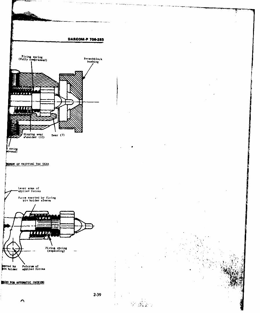
DANCOM-P T•70."
* letfiring spring 3rechblock(fully Co pressed) bloi k S~bushing
Sloping sear Sear (7)
s.outder (IC)
Pisrigsressedl
NIMNT OF TRIPPING THE SEAR
Lever arms ofapplied forces
Furce exerted by firingpin holder sleeve
Firing spring(expanding) -
i rted by Fulcrum of
++ I' •
,. holder applied forces : i
2-39"

AROOM-P 70"402
r:.
This page left blank intentionally
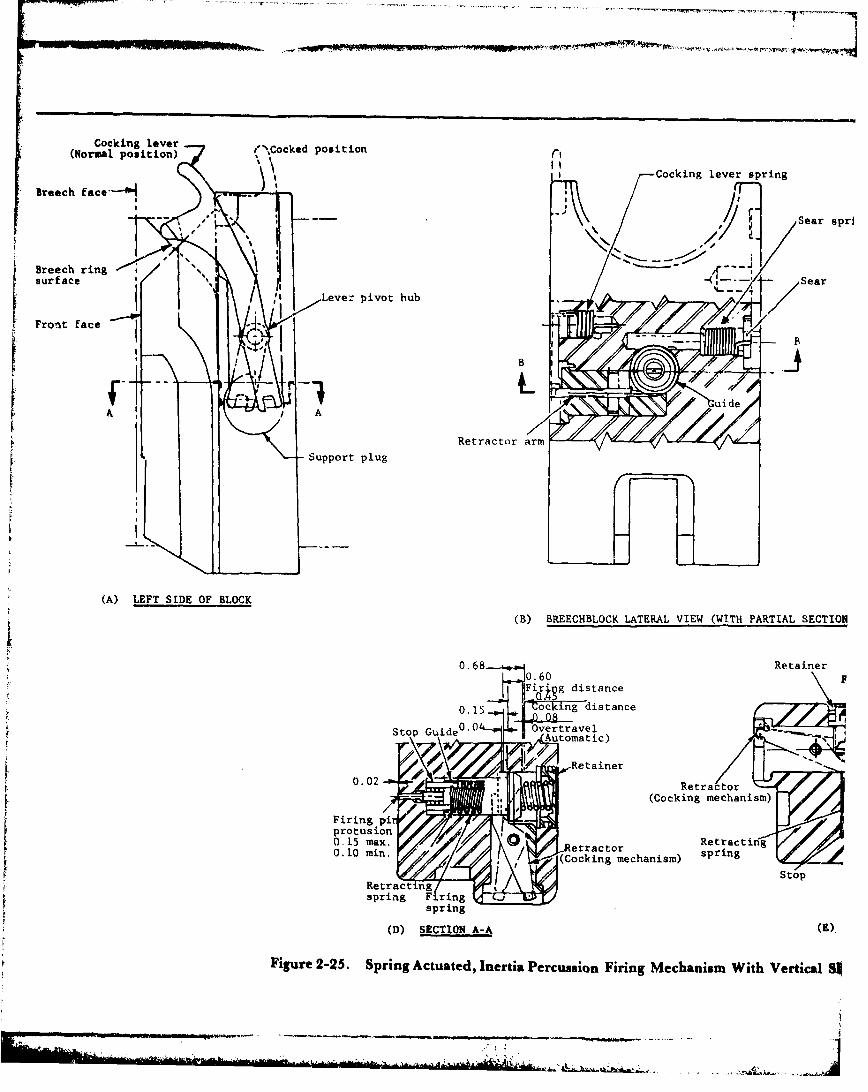
Cocking lever-%okdpstn(Normal position) Cokdpstn
-Cocking lever spring
Breech fc--0
-Ar
Sear sprl
Breech ringsurface Sa
Levez pivot hub
IIBRetractor arm
Support plug
(A) LEFT SIDE OF BLOCK
(B) BREECHBLOCK LATERAL VIEW (WITH PARTIAL SECTION
0.68 06 Retainer
F, distance
0. 15 oc ing distance
Sto 0 Gie 0 OvertravelStop uide utomatic)
I' Retainer0.02 Retractor
(Cocking mechanism)
pro tus ion
/ (Cocking mechanism) srn
Retract ng Sospring F ring %ý
spring
(D) SECTION A-A (E).
Figure 2-25. Spring Actuated, Inertia Percussion Firing Mechanism With Vertical S!
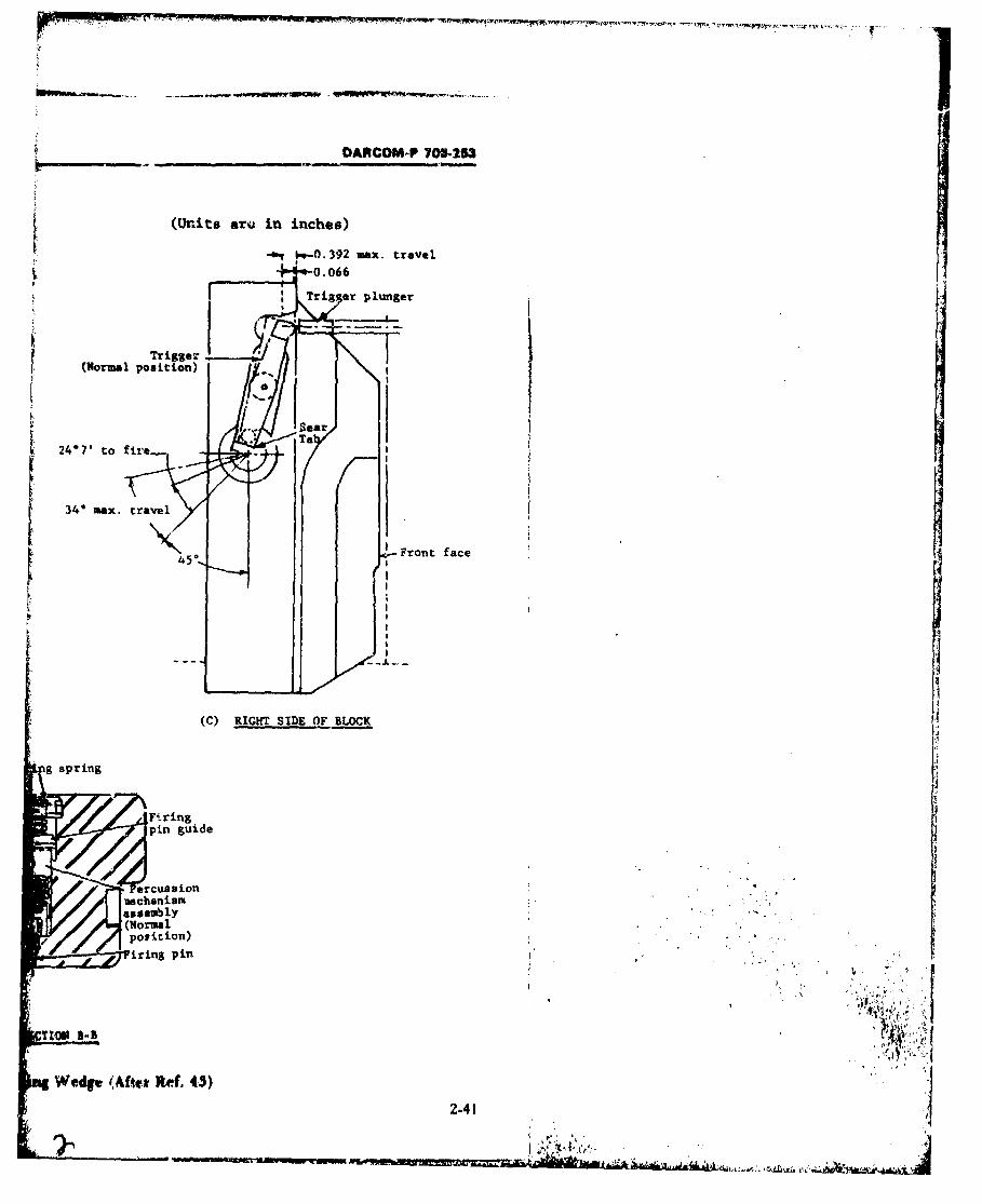
DARCOM-P 706-263
(Units are in inches)
- .s-O..392 max. travel!.•,_-_ "• 0.066
Tri• er plunger
Trigger _
(Normal position)
34* max. travel
4•/5, F ront face
I.I
(C) RIGHT SIDE OF BLOCK
g spring
,Firingpin guide
ercussion,aschanism.assembly(Normalpoui~tion)
iring pin
Wedge (Afier Ref. 43)
2.41

DARCOM-P 706-253
i.1
This page left blank intentionally
2-42
DARCOM-P 706-253
'M The trigger is a lever with a central hub, a cir- compressed firing spring toward the forward wallcular contact surface on one lever end and a of the breechblock. Here the prongs of the stopsmaller, shorter hub on the other end. The trig- strike the firing chamber wall and the stop isger is pivot-mounted to the breechblock upper halted. Meanwhile, the firing pin and its guideright side via the central hub; it also engages the continue forward by inertia. By this relative mo-sear tab groove through the small, lower hub. tion, the retracting spring, located between theFree movement of the trigger is restricted by the arrested stop and the firing pin head, is corn-sear spring. At the same time, the trigger upper pressed. After the firing pin strikes the casecontact is aligned in close proximity of the actu- primer, the retracting spring expands and with-ating phlnger (Fig. 2-25(C). draws the firing pin from the gun chamber into
A cocking assembly completes the overall the breechblock. Several methods of actuatingmechaniem complemnent. It consists of a long, flat the trigger plunger are possible. Fig. 2-26 is alever, pivot.mounted to the left side of the block; schematic of one version of electric solenoid ac-a cocking-lever spring; a smaller, pivoted retrac- tuation. The push-button convenience for tiring ator arm, laterally positioned in the block; and a cannon is preferred for combat tanks and otherslotted support plug for the latter member. The sophisticated self-propelled weapon systems.pivot hub is located near the cocking lever lower The designer's attention is further directed toend; this end is notched to provide a simple Fig. 2-25 for important engineering requirementsorthogonal connection for the tang end of the of this firing mechanism. Firing pin protrusionretractor (Figs. 2-25(A) and (E)). The cocking and retraction dimensions, and the several travellever upper end has complex contours, among or clearance distances of components indicated,them a finger-like extension for manual operation are typical specifications encountered in theand, for automated actuation, a round cam- design of firing mechanisms.follower area that is held against the breech ringcamming surface (Fig. 2.25(A)) by torsion spring 2-13.3 PERCUSSION HAMMERload at the pivot hub. The retractor inboard end This overali firing mechanism group consistslies in the path of the percussion mechanism and of a firing bI'ck that houses the firing pin anddoes the actual cocking. primcr holder (sometimes erroneously desig-
A firing mechanism cycle begins as the nated as Firing Mechanism, Ml-Refs. 44 andbreechblock iF. drawn downward (see par. 2- 45) and also the other major components. These11.2), camming the cocking lever clockwise, include the adapter and mechanism housing-Coriesponding motiors in the linkage system which retain the firing block in the breech-andcause the retractor to push backward against the the percussion mechanism or hammer that ac-percussion mechanism flange (Figs. 2-25(A) and tuates the firing pin. The adapter (Fig. 2-27) is(D)). The firing spring thereby is compressed an externally and internally shouldered sleeveagainst the spring retainer and is locked in that which fits into the rear end of the breechblockcondition by the sear. The sear is held in a fi:-ed bore through the carrier bracket. It is keyed inposition by action of its torsion spring. When the the carrier bore to prevent rotation with respectbreechblock is raises to firing position, the cock- to that member and is retained therein by theing lever is returned to normal position by its mechanists housing. The adapter has a flat, cam-separate torsion spring. shaped upper arm, notched to retain a safety
In firing, the trigger plunger makes contact plunger of the M1 mechanism when the cannonivith the trigger. This a.-tion rotates the trigger is ready to fire (Fig. 2-27(s)), and a rectangular
' , . and sear, the latter mo\,ng ou, of the path of the lower arm that support the percussion hammer. -* .fi,'ing pin guide flange. Upon release by the sear, In Fig. 2-27(A), the firing block is shown latchedthe percussion mechanism is propelled by tie in, firing poition. The firing block housing is a
2-43
A. .. A
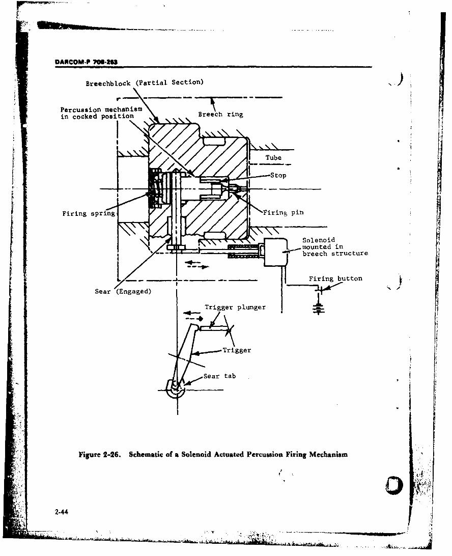
DANCOM-P 7106-263
Breechblock (Partial. Section)
Percussion mechanismin cocked position Breech ring
Stot
Firing springFrnpi
Sol1eno id______ mounted in
breech structure
t ' Firing button
Sear(Engged)Trigger plunger
-4
Trigger
Sertab
Figure 2-26. Schematic of a Solenoid Actuated Percussion Firing Mechanism
2-44J
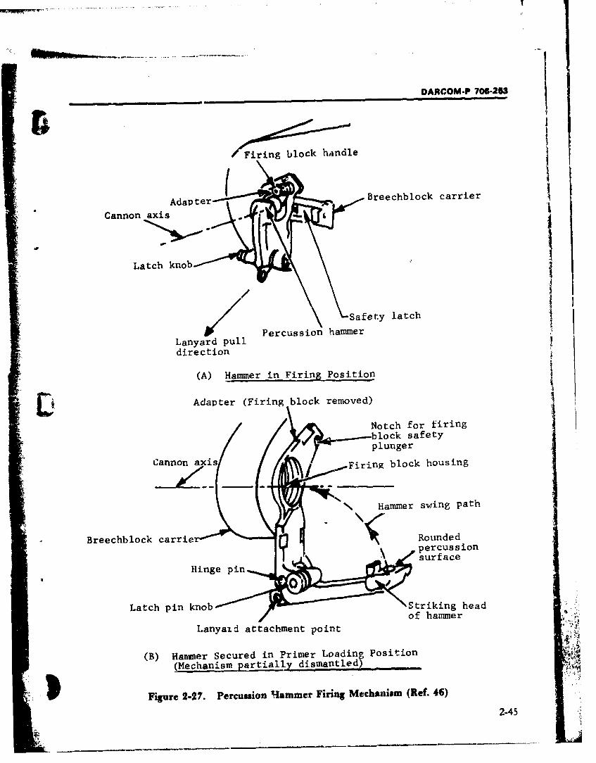
JI
DARCOM-P 706-253
egck handle
Adapter Breechblock carrier
Cannon axisel
Latch knob
Safety latchjPercussion hammer
Lanyard pulldirection
(A) Hammer in Firing Position_
Adapter (Firing block removed)
/Notch for firingblock safetyplunger
Cannon axis / Firing block housing
1 Hammer swing path
Breechblock carrie Roundedpercussion• surface
II .~~inge pin...
Latch pin knob Striking headS~~~of hammer i,.
Lanyazd attachment point J
(B) Hammer Secured in Primer Loading Position(Mechanism partially dismantled)
Figure 2-27. Percussion Hammer Firing Mechanism (Ref. 46)
2-45
DARCOM-P 706-253
shouldered cylinder that fits inside the adapter. housing in the rear of the breechblock. It is re- '•
It has a stepped central bore threaded at both moved and replaced as a unit between the firingends; threads in front secure the housing to the of successive rounds.obturator spindle while ,hose in the rear receive The firing block is a short, flanged cylinderthe firing block. (Although a different firing with a rim extending around more than half of itsmechanism type is involved, Fig. 2-20(C) is a rear periphery. This rim prevents the percussionvalid reference for component arrangement hammer from striking the firing pin unless thewithin the breechblock and carrier.) A safety mechanism is screwed into firing position. An'latch (Fig. 2-27(A)) protrudes into the adapter arm integral with the flange carries a springand firing block housing, interlocking the breech loaded plunger and handle by which theoperating group. Thus when the Firing Block mechanism is latched in firing position (Fig. 2-Assembly Ml (Fig. 2-28(A)) is in place, the 28(A)) and which is also used in removal andbreech cannot be opened (see par. 1-6.4). replacement of the block between rounds. A large
A harnnier and hinge pin, ano the hammer single-thread facilitates the procedure.latch make up the percus3ion mechanism. The As shown by Fig. 2-28(B), the firing pin has apercussioi, hammer is a lever which fits into a shouldered cylindrical body with a rounded rearfork of the adapter lower arm where it is pivoted contact surface and a flat-ended pin-like nose. Iton a hinge pin. Below the pin is a short arm, is held in the bore of the block by the firing pindrilled for attachment of a lanyard. The upper housing at the rear; and by the firing spring,arm of the hammer terminates in a rectangular guide, and primer holder at the front. The firingstriking head with a raised, rounded striking sur- pin guide is a cup which fits, closed end forward,face on it3 front face (Fig. 2-27 (B)). This surface in the forward end of the bore of the block; a holeimpacts the firing pin upon hammer actuation. A in the closed end supports the point of the firingrectangular projection is positioned below the pin (Fig. 2-28(A)). This spring is compressedstriking surface to strike a protective rim of the during firing between the closed end of the guidefiring block if the hammer is inadvertently trip- and the shoulder of the firing pin, and afterwardsped when the Ml mechanism is not in firing posi- retracts the pin inside the block.tion. (This safety feature appears in Fig. 2- The primer holder is ringshaped and has a left-28(A)). The hammer latch pin is a detent device, hand thread to prevent it from becoming looseWhen released as indicated in Fig. 2-27(B), it when the firing block is screwed into its housing.protrudes into the path of the hammer and pre- The holder screws into the front of the block,vents the hammer from being raised. This is a holding the guide and spring in place. IF: flangedpreferred position for inserting the firing block front has a U-shaped slot to receive the primerand primer cartridge. When the latch knob is case head and support it directly in front of theretracted, the pin is held from the path of the firing pin (Ref. 47). (When the firing block ishammer. The hammer is now permitted to swing removed from the breech, the spent primer car-in its arc to strike the firing pin, firing the weapon tridge is "extracted" by hand and a new primer(Refs. 47 and 48). Hammer actuation is pro- inserted.) The pr.mer is retained in position byduced by a vigorous pull on the lanyard. The the pressure of the firing spring bearing againstlatch pin also allows the hammer to be raise-d and the firing pin guide. The primer holder is locked'held in an upright, inoperative position con- in the block by a set screw that engages one of avenient when the weapon is traveling, number of notches machined in the rear edge of
The MI mechanism components consist of the the holder. The firing pin housing is also lockedfiring pin, primer holder and related parts, by a set screw, with a copper shoe inserted aheadhoused in the firing block as illustrated by Fig. 2- of the screw to prevent damage to the housing28. The assembly screws into the firing block threads (see both parts of Fig. 2-28).
2-46|SkL-a 4. . - .!
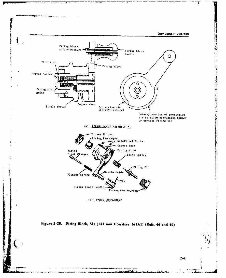
DARCOM.P 706.253[
6.handle
Single thread Protective Cutawa potio fpoetv(Safety feature,)
rim to allow percussion hammerto contact firing pin
(A) FIRING BLOCK ASSEMBL•Y Ml'i!
~rimer Holderiring Pin Guide
Cope Coperoho
Firing Firing Block,
Cutawayer ptFiring Spring
t coFiring Pin
SHandle GuidePlunger SpringFiring BlockHandle.k C ,
Firing Pin Housing
(B) PARTS COMPLEMNT.
Figure 2-28. Firing Block, M1 (155 mm Howitzer, MiAI) (Refs. 46 and 49)
2-47
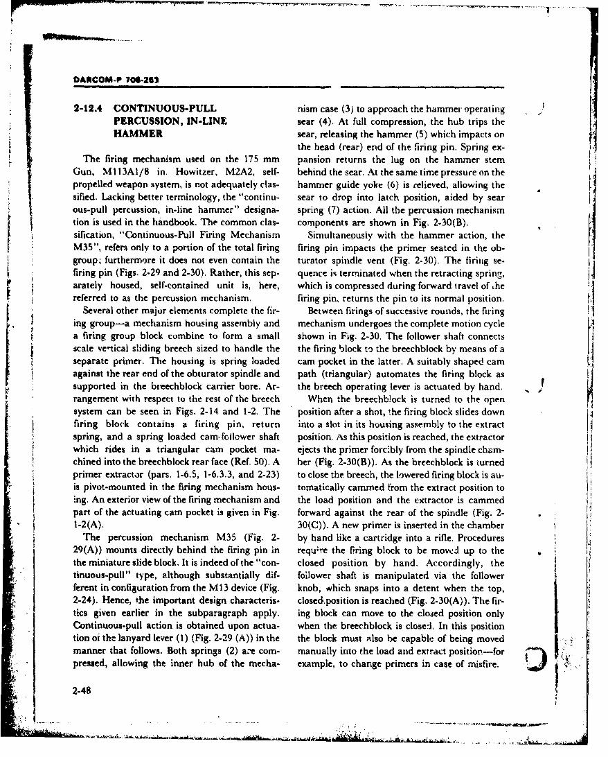
DARCOM-P 706-252
2-12.4 CONTINUOUS-PULL nism case (3) to approach the hammer operating )PERCUSSION, IN-LINE sear (4). At full compression, the hub trips theHAMMER sear, releasing the hammer (5) which impacts on
the head (rear) end of the firing pin. Spring ex-The firing mechanism used on the 175 mm pansion returns the lug on the hammer stem
Gun, Ml13AI/8 in. Howitzer, M2A2, self- behind the sear. At the same time pressure on the
propelled weapon system, is not adequately clas- hammer guide yoke (6) is relieved, allowing thesified. Lacking better terminology, the "continu- sear to drop into latch position, aided by searous-pull percussion, in-line hammer" designa- spring (7) action. All the percussion mechanismtion is used in the handbook. The common clas- components arm shown in Fig. 2-30(B).sification, "Continuous-Pull Firing Mechanism Simultaneously with the hammer action, theM35", refers only to a portion of the total firing firing pin impacts the primer seated in the ob-
group; furthermore it does not even contain the turator spindle vent (Fig. 2-30). The firing se-firing pin (Figs. 2.29 and 2-30). Rather, this sep- quence iq terminated when the retracting spring,arately housed, self-contained unit is, here, which is compressed during forward travel of hereferred to as the percussion mechanism. firing pin, returns the pin to its normal position.
Several other major elements complete the fir- Between firings of successive rounds, the firinging group-a mechanism housing assembly and mechanism undergoes the complete motion cyclea firing group block combine to form a small shown in Fig. 2-30. The follower shaft connectsscale ve'tical sliding breech sized to handle the the firing block to the breechblock by means of aseparate primer. The housing is spring loaded cam pocket in the latter. A suitably shaped camagainst the rear end of the obturator spindle and path (triangular) automates the firing block assupported in the breechblock carrier bore. Ar- the breech operating lever is actuated by hand.rangement with respect to the rest of the breech When the breechb!ock is turned to the opensystem can be seen in Figs. 2-14 and 1-2. The position after a shot, the firing block slides down 4firing block contains a firing pin, return into a slot in its housing assembly to the extractspring, and a spring loaded cam.follower shaft position. As this position is reached, the extractorwhich rides in a triangular cam pocket ma- ejects the primer forc'bly from the spindle chum-chined into the breechblock rear face (Ref. 50). A ber (Fig. 2-30(B)). As the breechblock is turnedprimer extractor (pars. 1-6.5, 1-6.3.3, and 2-23) to close the breech, the lowered firing block is au-is pivot-mounted in the firing mechanism hous- tomatically carmmed from the extract position toing. An exterior view of the firing mechanism and the load position and the extractor is cammedpart of the actuating cam pocket is given in Fig. forward against the rear of the spindle (Fig. 2- *
1-2(A). 30(C)). A new primer is inserted in the chamberThe percussion mechanism M35 (Fig. 2- by hand like a cartridge into a rifle. Procedures
29(A)) mounts directly behind the firing pin in requ;re the firing block to be moved up to thethe miniature slide block. It is indeed of the "con- closed position by hand. Accordingly, thetinuous-pull" type, although substantially dif- follower shaft is manipulated via the followerferent in configuration from the M13 device (Fig. knob, which snaps into a detent when the top,2-24). Hence, the important design characteris- closedposition is reached (Fig. 2-30(A)). The fir-tics given earlier in the subparagraph apply. ing block can move to the closed position onlyContinuous-pull action is obtained upon actua- when the breechblock is closei. In this positiontion oi the lanyard lever (1) (Fig. 2-29 (A)) in the the block must also be capable of being movedmanner that follows. Both springs (2) a'e corn- manually into the load and extract position-forpressed, allowing the inner hub of the mecha- example, to change primers in case of misfire.
2-48
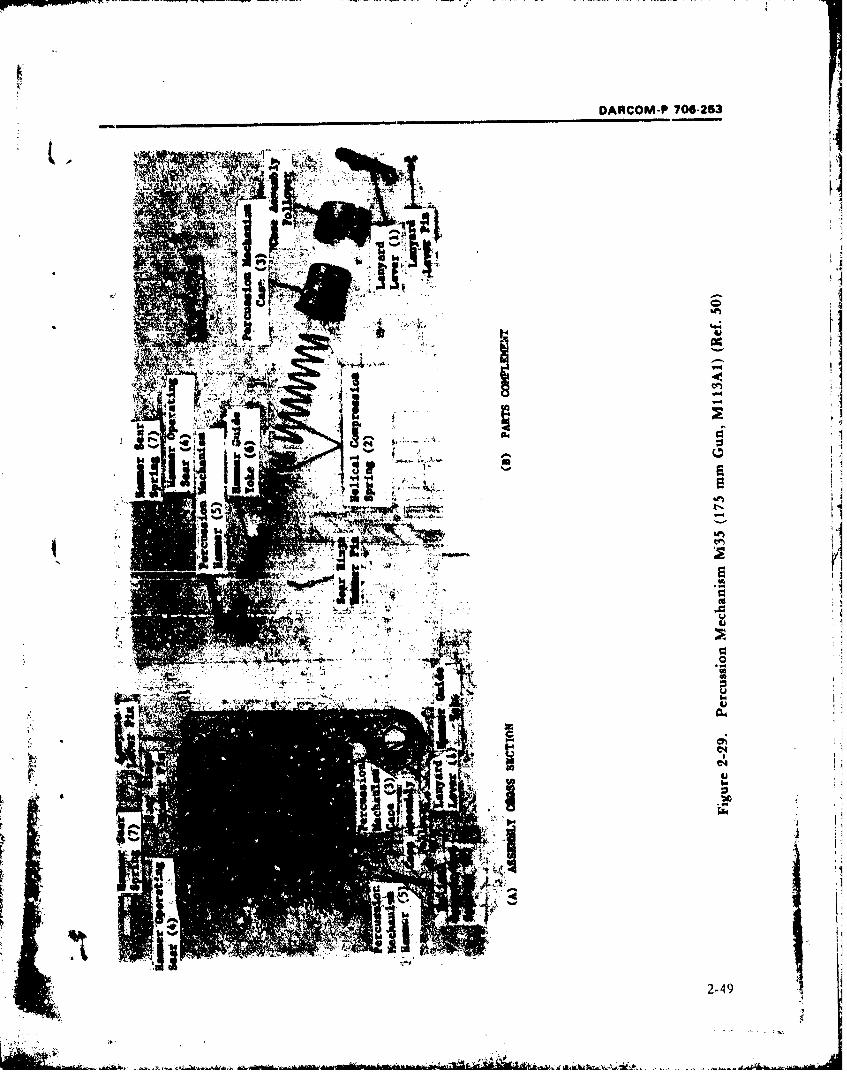
'K 1~.DARCOM-P 706-253
.1461
A*A
42-4
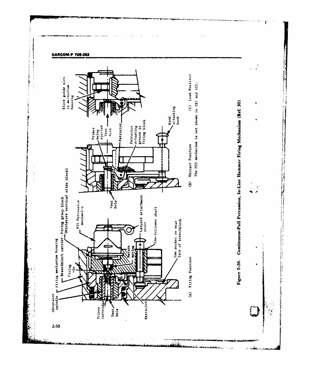
OARCOM-P 70645
.'0
or
m >~~O
0.0
4.11
~ - 4 4
a 0
AN -4 4
A 14
0644
2-50
OARCOM-P 706-253
2-13 EXTRACTING MECHANISM When a pair of uxtractors is used, these mem-bers are machined, one right hand and one left
"T'.is subassembly of the breech mechanism hand (Fig. 2-31 (A)), and are suppnrted vertical-has the primary function of extracting a "spent" ly in the front part of the breech-between the
t cartrdge case. These cases are used to house the sides of the breechblock and the inside walls ofpropellant charge for fixed, semifixed, and separ- the breech ring recess. The upper ends of the ex-ated ammunition and for the primer case used for tractors have inwardly projecting lips which lie inignition of separate loaded ammunition. Par. 1- recesses in the rear face of the tube when the gun6.5 provided a general functional description of is loaded and the breech is closed. In %he closedthis device and par. 2-11 illuminated the interre- breech position the lips lie under the rim of thelationship of the extracting and operating mech- cartri.dge case as indicated in Fig. 2-32(A). Theanisms. Cartridge cases, whether housing the lower ends of the extractors have a trunnion onpropellant or primer charge, are associated with each side. The inside trunnions ride in curvedsliding-wedge breech mechanisms since the case cam grooves in the breechblock, while the outsideprovides the sealing function. This paragraph trunnions are loosely held in "kidney-shaped"provides additional description and mechanism recesses inside the breech ring (Fig. 2-32). (Oneexamples. design variation offsets the outside trunnion
An extracting mechanism for a sliding-wedge above, or ahead of, the inner one; an example isbreech fulfills more than one function and these the horizontal sliding-wedge breech for the 105are worthwhile to summarize. The device: mm Howitzer, M101AI, shown in Fig. 2-14. In
1. Extracts the spent cartridge case from the this case, the outer trunnion is simply journaledweapon chamber (primary function). in the bottom of the breech ring, with the inner
2. Latches the breechblock in the open posi- trunnion engaged by a suitable actuating camtion for loading the next round. groove in the block.)
3. Triggers the closing or counterbalance As the breechblock is opened or pulledspring to close the breech, when tripped by the downward, the grooves in the block first guidenew round. the extractors into a gradual but powerful lever-
One or a pair of extractors is used in every age action in order to pry the case from the gunbreech. The device operates in the same manner chamber. Then, when the extractor trunnionswhether manual or semiautomatic actuation of reach the cuirves in the breechblock grooves, thethe breechblock takes place. In vertical sliding- forward radii of the extractors rock against the
block applications the extractors are symmetri- breech face (Fig. 2-32(B)). This motion impartscally placed; however, space constraints and the a rearward, rapidly accelerating thrust to the ex-operating mechanism arrangement usually per- tractors. The cartridge case rim, still engaged bymit only one extractor when the horizontal ,he lips, is cammed to the rear-thereby extrac-sliding-block motion is involved. ting the case from the chamber and ejecting it
Fig. 2-31 (A) shows a set of extractors as used from the weapon (Refs. 53 and 54).in a vertical sliding-wedge breech. These extrac- When the breechblock is full open, the innertors are representative of an older design in trunnions of the extractor ride over the top, flatvogue through World War II and the era shortly land in each extractor groove. A flat surface onthereafter. Nevertheless, this verison is still typi- the trunnion assures that the extractors are heldcal enough to convey underlying design concepts in place (Fig. 3-32(Q)). Thus, the extractors lockand illustrate operation of the mechanism. An the breechblock in the open position. In certainextractor design typical of current applications is breech designs the extractors are also latched in .i: .' -
covered later. place by spring loaded plungers applied againist - ..
2-51
• • _ .• ,. -. -.. , - *.. ... . ..
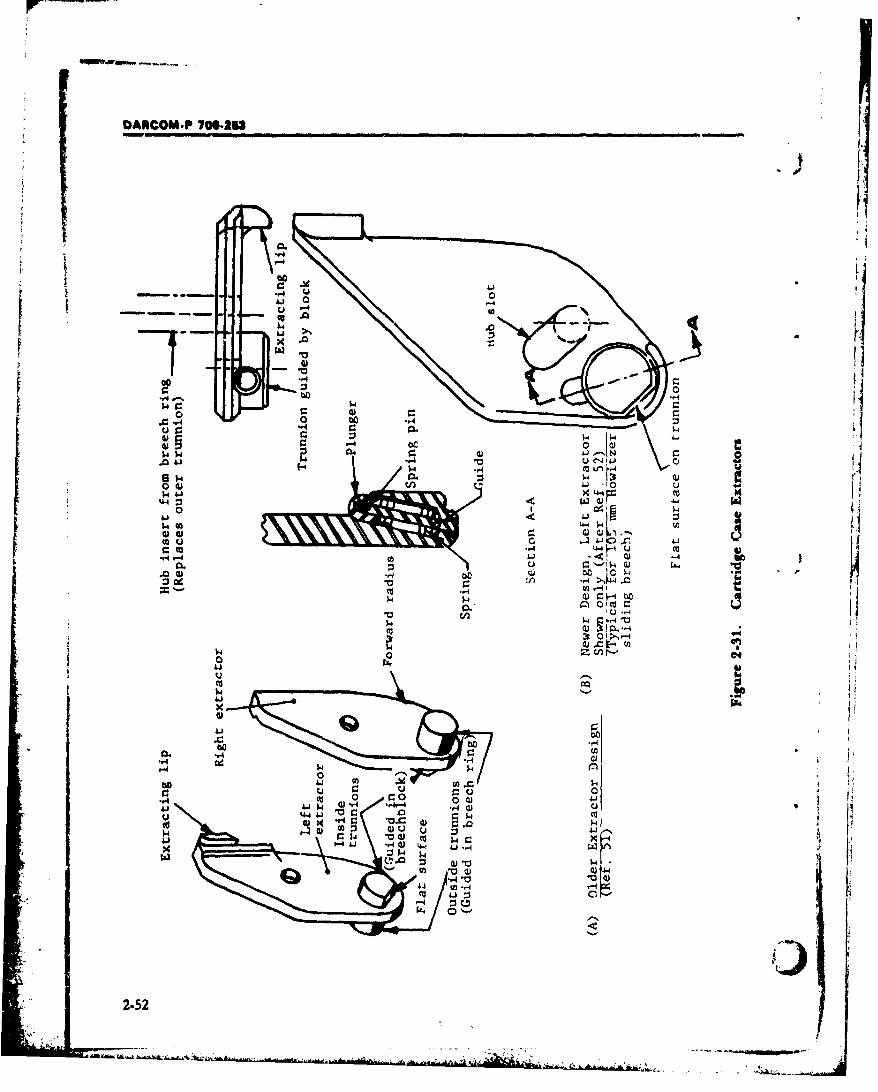
DARCOM.P 70622W
tt
-r4
-. 44
414
UII(U'
00
r-4
0o r.r4) 0r '0= 04) w
go 4). U
9-4 4J-4.-W-.
4.11
2-52i
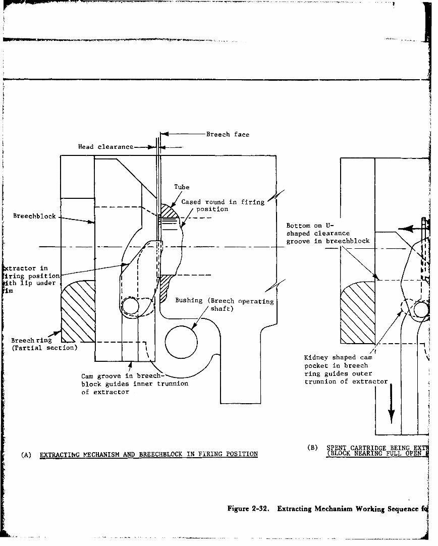
Breech face
Head clearance
' Tube
Cased round in firingposition
Breechblock.
Bottom on U-shaped clearance
__.... __ groove in breechblock .,
jii
Iring position _•th lip under I -
Bushing (Breech operating -shaft)
"Breech ring(Partial section) /1
__Kidney shaped campocket in breech
Cam groove in breech- ring guides outer
block guides inner trunnion trunnion of extractor
of extractor
(B) SPENT CARTRIDGE BEING EXT•(A) EXTRACTING MECHANISM AND BREECHBLOCK IN FIRING POSITION (BLOCK NEARING FULL OPEN
Figure 2-32. Extracting Mechanism Working Sequence
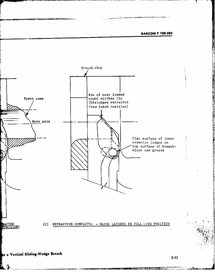
DARCOM-P 706-2•3
Breech ring
/I
Rim of next loadedSpent case round strikes lip
(Dislodges extractorfrom latch position)
.Boreaxis--
Ii: II
Flat surface of inner
trunnion lodges on'1 top surface of breech-
block cam groove
OCTED (C) EXTRACTION COMPLETED - BLOCK LATCHED IN FULL iWEN POSITION
r a Vertical Sliding-Wedge Breech2-53

1I,
DARCOM.P' 7-2S3
%0 lb
I •This page left blank.'
I2
SnN)
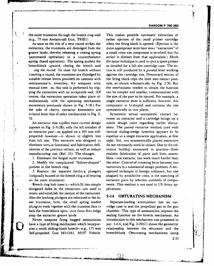
II DARCOM-P 700-253
the outer trunnions thcough the breech ring wall This makes possible automatic extraction or(e.g., 75 mm Antiaircraft Gun, T83EI). rather ejection of the small primer cartridge
As soon as the rim of a new round strikes the when the firing block is opened. (Ejection is theextractors, the trunnions are dislodged from the more appropriate term here since "extraction" ofgroove lands, thereby releasing a ciosing spring a small arms size component is involved, but the(automated operation) or a counterbalance action is distinct from that application.) Muchspring (hand operation). The spring pushes the the same technique is used to eject a spent primerbreechblock upward, closing the breech and as detailed for a full size cartridge case. The ac-
zing the round. To close the breech without tion is still produced by a pivoted lever workinginserting a round, the trunnions are dislodged by against the cartridge rim. Downward motiorn ofsuitable release levers provided on cannons with the firing block trips the lever into extract posi-semiautomaric breeches; fer weapons with tion, as shown schematically by Fig. 2.30. Butmanual bree, es, this task is performed by trip- the mechanisms needed to obtain the functionping the extractors with an acceptable tool. (Of can be simpler and smaller, commensurate withcourse, the extraction operation takes place si- the size of the part to be ejected. For example, a
multaneously with the operating mechanism single extractor lever is sufficient; bowever, thismovements previously shown in Fig. 2-18.) For component is U-shaped and contacts the rimthe sake of clarity, extractor kinematics are symmetrically in two places.isolated from that of other mechanisms in Fig. 2- Symmetric versus asymmetric contact be-32. tween an extractor and a cartridge brings up a
An extracto" that typifies more current design subtle design point regarding earlier discus-appears in Fig. 2-31 (B); only the left member of sions. The paired extractor method used withan extractor pair-as applied on a 105 mm self- vertical sliding-wedge breeches appears to bepropelled howitzer-is shown in slightly less superior to a single extractor application, at firstthan full size. This extractor was designed to sight. Yet, two symmetrically placed extractors
eliminate certain functional and fabrication defi- do not necessarily work in unison. Due to the tol-ciencies of the previous verison, as well as reduce erance buildup encounted in practice-frommanufacturing cost (Ref. 55). The changes: realistic fabrication of parts and from assem-
1. Eliminate the forged outer trunnions. blies-one extracto. can work much harder than2. Modify the complicated "kidney-shaped" the other. Control of actuating force between two
pockets -in the breech ring. extractors is a substantial design problem. A rec-
3. Replace the separate latchix.g plungers ognized technique in foreign ordnance, but one(originally housed in the breech ring aad bearing plagued by prohibitive costs, is the matching ofon the outer trunnions). extractor pairs by selective assembly of compo-
Breech ring hub inserts-which fit into simple nents. This method is not used in US Army ap-elongated holes in the extractors-are used to plications.retain and establish the motion of the extractors.Also the latching plungers are relocated to the in- 2-14 OBTURATING MECHANISM
ner trunnions; here, the small spring loaded Separate-loading ammunition has no car-plungers work together with the trunnion flats to tridge case to seal the propellant gas in the gunlock the breechblock open, ornce thome flats lodge chamber. This type of ammunition imposes theatop the extractor groove lands. sealing function on the breech mechanism. An
Newer weapons firing bagged ammunition introduction to this mechanism was presented inhave a type of firing mechanism which .ncorpor- par. 1-6.6, and Fig, 2-20(C) shows the geometricates a small sliding-block breech--e.g., 175 mm relationship between the obturator and theSelf-propelled Gun MI13A1, M107 Vehicle. breechblock. Obturating mechanisms using
2-55
DARCOM-P 706-223
DeBange type sealing pads are conventionally wire basket envelope are representative of the
used in interrupted-thread breech mechanisms, current materials used. These meet nearly all im-Table 2-2 lists the principal design require- posed requirements and are in use. but even they
ments associated with Debange type elastic ob- have some shortcomings-for one, oss of re-turator pads. Qualitative requirements-like the siliency near the low temperature extreme (Ref.sealing technique itself-are not new, but quan- 58). Current obturator design receives furthertitative demands such as propellant gas pressure treatment in the handbook from the viewpoint ofand weapon heating effects inevitably increase material seiection and processing (Chapters 3with time. For the artillery weapon missions be- and 4, respectively).ing corsidered, propelling charges are incre- The DeBange obturating mechaiiism consistsmerited. Thus, maximum chamber pressure is of the elements shown in Fig. 2-33(A). The rings,not the only design specification for an accept-able obturator, as hrdicated in the table. The pad, and washer disk are assembled under theahead uftr ths indicated ipidn proere taaperedMnumber and combination of materials tried for head )f the obturator spindle properly tapered
this application is an exhaustive topic. Llastic for this putpose. The smooth front shape of thesteel mushroom head prevents pinching of thematerials, both rigid and flexible, have been con- cth propl bag whenth brechis osed.cloth propellant bag when the breech is closed.
sidered; these range from metals, to rubbers, to This also avoids possible damage to the chargeplas!.cs, etc., aside from the fillers or binderswh "h are also necessary. The subject is exhaus- (Ref. 56).
e ., beyond the scope of this handbook; however The front and rear split rings are triangular invaluable ba.ckground information appears in cross section and have conical outer surfaces thatRefs. 56 and 57 on the chronology of -develop- correspond to the shape of the gas check seat in )ments through World War ii. None of these the cbarnbe,. They are made with an overlap-materials has met the application requiretnents ping tapered joint (Fig. 2-33(B)), and slightlysuccessfully. Special polyurethane elastome,'s o-,ersize to the seat surface (on the order of 0.01and silicone-asbestos formulations contained in a in., diametral measurement when in a free state).
TABLE 2-2 PRINCIPAL DESIGN REQUIREMENTS OFELASTIC OBTURATOR PADS (Refs. 56 to 58)
Physical Property Material 'tequiremeLtt"1Tenip" ature I Rimain functional throughout the climatic extrem!:s of the military environment
,(see Chip~tr 2'. Requirements particulary dvsired over the wide temperaturerange are:a. Low coefficienit of thermal expansion, andb. Not less than 25% of -riginal resiliency.
2. Withstand beat developed in the gun due to firing (300*F withnut permanent&'format'on or physical change).
Compressive Pressure I. Respond well to the lowest pressure developed in the gun.2. Withstand the highest pressure developcd-wh;le fully constrained. (Pressure
______.____ range: approximately 8,000 to 60,000 psi.) ,
Elasticity I1. Remain sufficiently elastic to confor m to its seat in the chamber, yet2. Stay dimensionally stable for long and repetitive use.
Adherence MAtk pvoptr contact with the chamber surfaces for seating, without sticking .I"-" ' ,: in place and hindering breechblock opecation. _ _ _ _ _ _
Miscellaneous Properties I. Producibility-from noncritical materials; with commercial equipment; toreasonable close tolerances (0.020 in.).
2. Immunity to oils, solvents, fungus, and effects of weather.3. Stable shelf line (Q 3 yr). '
2.56
S"I,•'. . . ..- , , ,. - . , .. .,• ; ' •',,?k ,• ir " , _ ' . ,,
r UARrOM-P 708-253
It
T -..
Zi- .. W
()Obturator Cmous(175- m- Gun, )lk)(e. 0
Section A-A
(J~f1 9)
Figure 2-33. DeBange Obturating Mechanism
2-57
DARCOM-P 706-253
But, with the breechblock in the closed position, cased ammunition; however, the small cartridge . )the hardened steel split rings compress to make size can be problematic. Effects due to the primerpositive contact with the seat (Ref. 59). The charge are well accommodated, but the moreshape of the split rings is such as to protect the serious main charge reaction must also be con-edges of the elastic obturator pad nested be- tained within the passage.tween them from being pinched against the seat. The breech designer is confronted with expan-A small inner ring fits between the spindle shaft sion type obturators when special ammunition- Hand the center hole in the obturator pad to pre- breech combinations come into play. To date thevent extrusion of the elastic pad material (Fig. 2- scene is limited but two significant applications
33(A)). (Solid inner rings have been found can be cited. Lh t~te British CH!EFTA.IN tar.k ,satisfactory in modern design practice, but in with a 120 mm gun, the vertical sliding-wedgeearly breech models this part of the obturating breech is combiaed with se ,arate-loadingmechanism was also split.) (bagged) ammunition. Desirability of this breech
The obturating mechanism assembly is type for rapid fire tactics and the ammunitionmounted to the breechblock carrier under axial handling advantages derived are justified-byspring load and keyed there against rotation. way of design trade-offs-against the need for aHowever, the breechblock can-. rotate about the more complex obturator. The system is opera-
obturator due to its own carrier mounting (refer tional but not troublefree. According to Ref. 61,to Fig. 2-20(C)). A steel disk or thrust .vasher is obturation is developed with a loose metallic ringthe obturator mechanism component that separ- at the mouth of the chamber. The flexible metal-ates the rotatable block from the stationary lic ring is forced against the block face by gasassembly. The thickness of this disk, closely fitted pressure and seals the chamber. Thus, it per-to the spindle diameter, is sized to put the proper forms the function of the conventional brass case.initial compression on the obturator pad when Additional details of this obturating mechanismthe breech is closed Anadditional shim disk may can be found in Refs. 30 and 62.be added to the assembly as necessary, to obtain The 152 mm Gun/Launcher (M81 and M162a tighter seat for the gas check pad. A vent hole versions' in our service employs a flexible metalthrough the obturator spindle has the purpose to ring obturator for firing fixed, consumable casedirect flame from the primer into the main pro- ammunition and also a guided missile round.pellant chamber when the weapon is fired (refer This obturator is similar in operating principle toto Fig. 2-30). the preceding application, but has a different
A.s previously mentioned, the DeBange system geometry which appears schematically in Fig. 2-uses a compression principle to obtain the gas 34. It relies on the radial expansion of the thinseal. When the gun is fired, propellant gas tapered ring when exposed to propellant pressurepressure pushes the mushroom-head against the (Ref. 63). The ring is retained in the fixed cham-"obturator pad, compressing the pad between its ber, but when the separable chamber is closed,axial r'estraints. In turn, the resilient but con- the doubie-taper ring makes contact with gasfined pad material expands radially-along with check seats in each chamber portion. The obtur-the two split rings-against the chamber seat, ator seal is pressurized against these chambersealing off the opening against passage of gases to seats when the round is fired but it relaxes whenthe rear. An obturator of this type will become the load dissipates.
tighter as the gas pressure rises, effectively seal- Expansion type obturators have been used ining all pressures. only two US wea•pons (152 mm M81 and M162)
Obturation of the breechblock vent hole is per- by 1978. This limited use makes it inappropriateS-formed by the primer seated in this opening. Car- to provide design requirements similar to those in
tridge case expansion is utilized, much as for Table 2-2 (for elastic type DeBange type pads).
2-58
OARCOM-P 706-253
Seal seat
Metallic gascheck ring
held in fixedchamber
Bore axis
It
Seal seat
Separable chamber
Fixed chamber
Figure 2-34. Expansion Type Obturator, Separable Chamber Breech Application (Ref. 63)
2-59
* -
DANCOM-P 70.-25 ,.._ _ _
SECTION V. FUNCTIONAL REQUIREMENTS }
This section of the handbook expands descrip- Power assistance used for certain breech func-tions of the functional aspects ~of the breech tions, does not constitute "automatic" operation.mechanism. The topics covered are the methods Ihis has been a misconception in the past, stem-used tor operating the breech mechanism, the ming from association of recoil energy actuatedsignificance of the interfaces arising from gun ele- breeches with a number of self-propelledvating and traversing mechanisms, and opera- weapons. It should be emphasized that for theting simplicity. sizes of weapons under consideration in this
handbook, fully automatic operation does not yet-OPERATING METHODS exist. The closest approach to full automation
Breech mechanisms are operated manually 9r has taken place in some large caliber antiaircraftsemiautomatically by means of internal or ex- guas. But this has been accomplished only at theternal power sources. Semiautomated mech.- expense of great overall weight and size, depend-nisms are provided with a manual operating ca- ence on supplementary power supplies, and sac-pability. This aspect of the breech mechanism rifice of mobility-e.g., the 120 mm Antiaircraftwas introduced in par. 1-6.2 and is amplified in Gun, M1 (see Table 1-1). At the same time,the subparagraphs of this section. greater problems are also exposed in the areas of
availability, reliability, and maintainability.2-15.1 MANUAL OPERATION The use of terms like "automated" and "auto-
Breech operation in large caliber guns takes matically operated" breech as used in the hand-place either by manual or semiautomatic means. book is just a convenient adoption of the vernac-Hand mode is the classification wherein the ular of the day, and such terms should be inter-energy required to operate the breech mecha- preted "semiautomatic mode". Power to performnism through the cycle of loading, closing, firing, automatic actions can be supplied by energyopening, and case extraction is supplied by the sources either internal or external to a gunoperator. Accordingly, design is made as simple system.as possible for minimum manual effort and maxi-mum convenience of the gun crew. This method 2-15.2.1 INTERNAL POWERof breech operation is most often used with towed Two sources of internal energy power are (.weapons where crew size, space allotments, and available to a weapon system; namely, propel-other offsetting conditions make it competitive lant gas energy and recoil energy. The use of pro-with more complex design alternatives. pellant gas involves diversion of a minor quanti-
ty of the gas from the chamber into a small cylin-2-15.2 SEMIAUTOMATIC der. The gas drives a piston connected to the
OPERATION breech mechanism. When using this method,
The term "semiautomatic mode" applies to both the great erosive power and the highbreech mechanisms in which some portion of the pressure exerted by the propellant gas must becycle of loading, closing, firing, opening, and case taken into account. Propellant gas has been usedextraction is automatically accomplished. The for driving breech mechanisms in small caliberremainder of functions are performed either gun systems--e.g., the 20 mm fully automaticmanually or by manually controlled external gun-but has not been successfully used for largepower. Semiautomatic breeches are usually as- caliber weapons like the 103 mm howitzer.sociated with tanks, self-propelled artillery, or Recoil energy is the most common internalother weapon usage for which a more elaborate power source, to date, for large caliber breech ac-breech is tactically justified. tuation. This method takes advantage of the
2-60
OARCOM-P 706-253
r-,coil and counterrecoil movement relative to sta- and size of ammunition, fighting compartmenttionary parts to operate the breech mechanism. space, as well as whether internal power is avail-Strictly speaking, the counterrecoil portion of the able are con3traints to consider (see par. 1-4 andcycle performs the task. The method is most Chapter 2, Section V).compatible with linear motions of a sliding-type For the size of weapons considered in thisbreech. Here, the interaction between stationary handbook, the types of auxiliary power sourcescamming parts and an operating mechanism available aremoving with the breech in counterrecoil operates 1. Hydraulic or electrica crank to slide the breechblock open. Actually a 2. Stored gas. .
number of specific functions can be automated Hydraulic or electrip power can be used to ac-which may be summarized as: complish almost all breech functions but its com-1. Breech opening -- Direct cam actuation in mon assignments are breech opening/closing,
counterrecoil and loading/ramming tasks. Loading/ramming
2. Firing mechanism reset - Device is cocked of ammunition within the context of this hand-by breechblock movement book is an interface function rather than a h
3. Breech locking -. Direct case actuation primary breech design factor, Nevertheless, this4. Case Extraction - Extractor levers work in function is a significant example of external
conjunction with the operating mechanism power utilization and accordingly is introduced5. Breech latching - Extractors lock the in Fig. 2-35. The system involved is treated later
breech open to receive the next round of ammu- in this chapter.nition Depending on the weapon application, sup-
6. Breech closing - Store,. energy of a closing plementary power may be required to operatespring is trigg-red. the breech directly. Guided missile weapons are
Some examples of recoil energy usage are the particularly good examples of the need for ex-75 mm Antiaircraft Gun T83E1 (towed); the 155 ternal powei- assistance, because of, among othermmn Self-propeld Howitzer, M126AI (M109 things, the low propellant and recoil energyvehicle); -ndanumber of tankg,is (seeTable I- availability. An example of the most sophisti-2). Preference should be given to the develop- cated and advanced use of breech external powerment of semiautomatic breech mechanisms is the 152 mm Gun/Launcher (M81 and M162which cai, perform rapid fire without depend- versions). It fires dual ammunition, i.e., bothence on external power sourc',., which are not guided missiles and conventional medium-always available or dependable. velocity projectiles from the same rifled tube. An
illustration of the unvsua! electric-driven breech2-15.2.2 External Power mechanism is given in Fig. 2-36. The illustration
The availability of .-xtern-l power to operate is presented early tr give an idea of the complex-the breech dtoes nothirg to change the operation ities that c-,n be expected in breech design. Thisclassification from "'emiautomatic mode", as wea[,Dn is further discussed in pars. 1-4.2 and 1-stated previously in par. 1-3.3. The tvv- ef 5.4.weapon under consider;nt-tri ha• a gr,'at in- Although a definite -xternal power source,fluence regarding the use of exta,",,.l power stored gas er,-rgy is currently limited to another-,ources. If power is aleady available, the use of it peripheral breech function, e.g., it is used toto perform breech op.-ations is more attractive. powe scavenger devices for prging propellantS.Self-propelled weapons are naturally more easily residue from the gun chamber in tank applica-given power assistance than towed weapons Lions. Again, the 152 min Gun/Launcher is citedbecause of the existence of a power plant, but this as an example of such an app!ication. This sub-criterion is not the only one which applies. Type ject receives additional treatment in par. 2-7 in
2-61
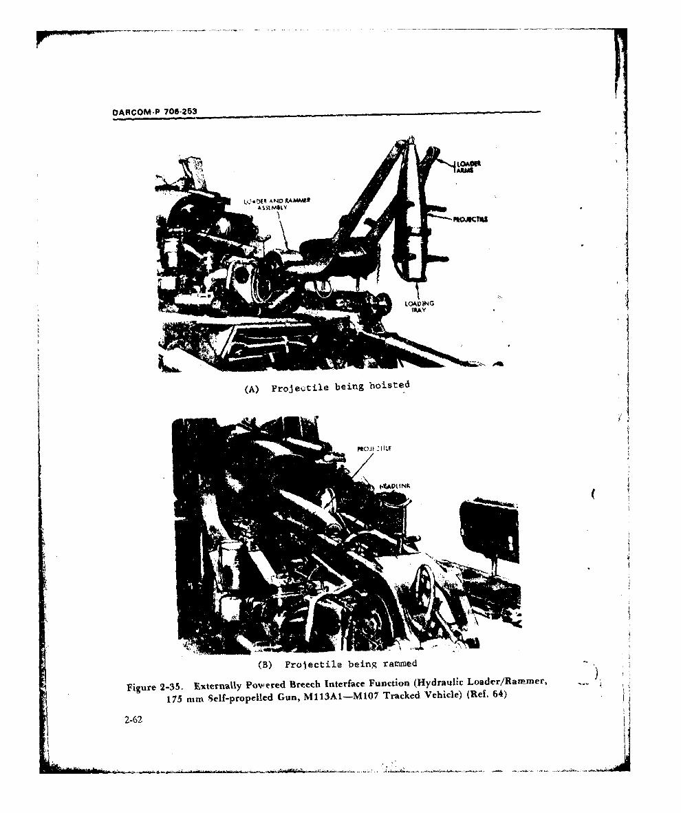
OARCOM-P 700-253
LQ DER A PD4 KAMD*3
VMOM
(B) Projectile being rammied
Figure 2-35. Externally Po-wered B~reech Interface Function (Hydraulic Loader/Ran-mer,
175 nun Self-propelled Gun, M113AI-MI07 Tracked Vehicle) (Ref. 64)
2-62
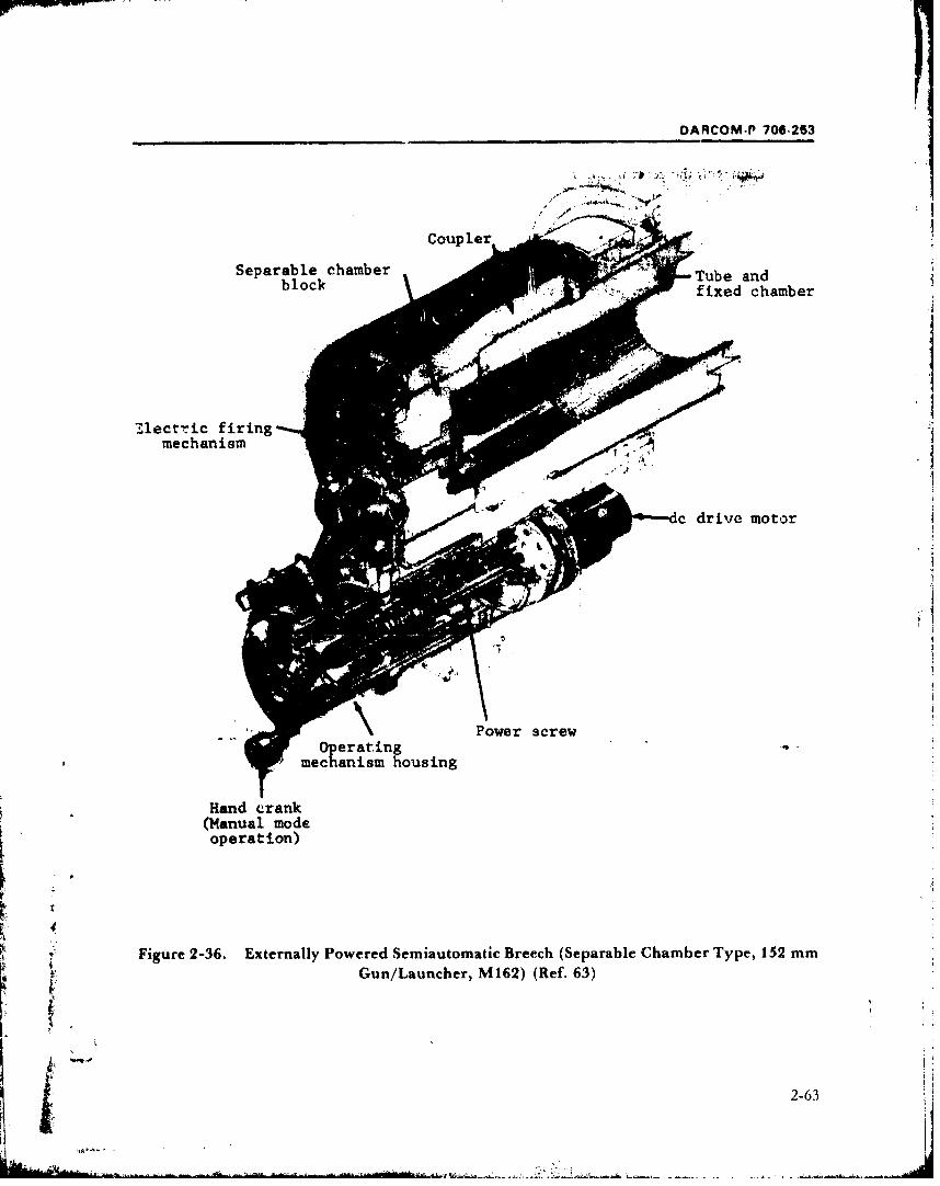
DARCOM-P 706-253
Separable chamber Tb nfixed chamber
7.lectric firingmechanism
c drive' motor
Power screw .
Operatingechanism housing
(Manual modeoperation)
Figure 2-36. Externally Powered Semiautomatic Breech (Separable Chamber Type, 152 mmGun/Launcher, M162) (Ref. 63)
2-63
OARCOM-P 706-263
conjunction with the general topic of bore evacu- the breech mechanism (closed) during recoil,ation. the operating mechanism, and other appurte-
nances. When fired at any combination of eleva-2-16 ELEVATING AND tion and azimuth angles, the breech proper must
TRAVERSING INTERFACES not come in contact with the ground (or base) orany portion of the mount.
Major subsystems of a weapon system include:weapon (gun), fire control, mount, loadler/fam-nmer, and ammunition. The mount or carriage, as '1
it is sometimes referred to, has the following sub- 2-17 OPERATING SIMPLICITY
assemblies and for which AMC Engineering The military environment in which materiel isDesign Handbooks have been published: required to function cannot tolerate elaborate op-
.AMCP 706-341 Cradles erational procedures. Operations must be as sim-AMCP 706-342 Recoil Systens pie as the required functions pcrmit. Operations
SAMCP 706-343 Top Carriages often take place under adverse conditions. ThereAMCP 706-344 Bottom Carriages are extremes of temperature-heat and cold.AMCP 706-345 Equilibrators There are interference problems due to rain,AMCP 706-346 Elevation Mechanisms snow, dust, and mud. There are times whenAMCP 706-347 Traversing Mechanisms. equipment seffers from neglect and times when it
The breech mechanism has an important in- suffers from abuse and misuse.terface with the gun mount which arises from the Simplicity of the design itself, foolproof func-elevating and traversing of the gun and the re- tioning, and ease of mechanical operation arequirements for loading ammunition under all goals to aim for. Some practical examples of op-combinations of quadrant elevation and azimuth crating simplicity are:(traverse). Another interface exists during recoil; 1. Locating controls and actuators conven-the breech mechanism must not contact any por- ientlytion of the mount or ground during firing at any 2. Providing special devices to facilitate thecombination of elevation and azimuth. Tables 1- work of the crew (loading devices, counterbal-I and 1-2 summarize recoil distances, elevation ances for operating mechanisms, etc., dependingangle extremes, ard traverse angle bounds for upon weapon caliber).typical weapons. As new or different caliber weapons are con-
The designer should ascertain the geometric sidered in the future, for requirements of morerelationship between the weapon mount and the rapid performance, etc., automated functionsextreme combination of traverse and elevation will play an even greater role in breech designangles as well as the recoil distance. Functional than now. At that time, the breech mechanismlayouts made during the design process (pars. 1- may also be required to absorb functions which8.1, 3-5, and 3-6) must show that adequate clear- at present are external to it. Operating simplici-ance is proided during ammunition loading op- ty must also be retained in such new designs.erations. This clearance includes provision for Operating simplicity will encompass the ap-the gun crew, loading tray and rammer function plication of human engineering, maintainabilityas applicable, with the breech open. It should engineering, and design for reliability. Thus, foralso be shown that the firing mechanism can be example, the gun crew operating controls mustoperated under these conditions. not only be conveniently located, but should be
Initial functional layouts should also be designed so that in Arctic use the protective:prepared which show the spatial relationship of clothing worn by the crew will not interfere with
"2-64
DANCOM-P 7M0263
S operations. T1his dictates control geometry and mum use of "intricate" mechanisms. Thosemotion usable with bulky clothing and hand pro- devices which require close tolerances and "finetection. Conversely, gun operation in eAtremely adjustment" are subject to operation degrada-hot regions may cause controls to become exces- tion under these conditions. The designer shouldsively hot which would also interfere with gun make himself aware of the in-service operationalcrew efficiency functions. performance records of weapons similar to the
just as the crew is adversely affected by type he is designing or for those which haveclimatic extremes, so will the breech operating similar devices employed. Design guidance maymechanism. Field use (rough handling) in con- be obtained from either good or bad perform-junction with climatic extremes dictates mini- ance records.
SECTION VI. DESIGN REQUIREMENTS
In addition to complying with the specific opening, case extraction, and gun gas evacua-
hardware constraints described, the designer tion. Other limits are imposed by the ammuni-must consider a number of more general but tion; i.e., weight, geometry (diameter and
posed by rate of fire; weight, space, and dynamic sociated magnitud-) source available for auto-loading; by the need for safety and reliability; by mating breech function also may impose limits.the requirements for an effective man/machine Ref. 65 presents a British analysis on rate ofrelationship; and by conditions imposed by the fire. This analysis had two objectives, to deter-environment, mine: (1) the gun cycle which would have the op-
2-18 RAT OF IREtimum rate of fire and (2) the dependency of thisRATE O FIRErate on muzzle velocity, projectile weight, and
Te broad relationship of the rate of fire to the shape and propellant type. The conclusionsweapon system was presented in par. 1-4.4. The which apply in the realm of this handbook arebreech mechanism functions which contribute to that the weight of the moving breech componentIthe cycle time, and are therefore under the con- and the distance moved through should betrol of the breech designer, are: minimized to the greatest extent possible. In ad-
1. Locking and unlocking dition, the synchronization of the recoil cycle and2. Opening and closing breech opening should be optimized in relation-3. Case extraction ship to the gun pressure decay characteristics.4. Primer initiation The breech mechanism design team does not5. Chamber evacuation or scavenging, have responsibility for the major contributing
Even though the design of the mechanisms which factors which control or bound the weapon firingpertorm these functions are part of the total rate. It lies with the ammunition and recoilbreech subassembly design, there are significant design groups. However, the breech interfaces re-systemn imposed constraints. lating to the gun crew and the functions cited are
The ammunition provides one such limitation important.by virture of the gun pressure curve. There is a 219 W IHdistinct pressure decay time which occurs after 219 EIHthe projectile exits the gun muzzle and must be Weight is one of the strongest constraints im-' recognized before it is safe to initiate the breeh posed on ordnance design. A major design goal ismechanism opening sequence of unlocking, to derive the greatest strength for the lowest
2-65
r OACOM-P 706-2S3
weight. Although concern for excess weight in of an overall system with unfavorable results.military equipment is not new, modern weapon Rational weight apportionment is more complexrequirements demand that weight budgets be and must satisfy thc needs of various gun ele-more closely scrutinized. Mobility-in its own ments. Although recoiling parts often receiveright or to facilitate transport-and versatility such emphasis, the lowest recoiling weight doesare important weight related factors. not necessarily provide best weapon perform-
Definite weight constraints apply to breech ance (Ref. 66). Breech mechanism weight can, ofmechanism design. However, the critical course, influence the role of recoiling parts andstrength required of the breech makes substan- the total weapon weight. Self-propelled artillerytial wý-'itht reductions impossible. In addition, can have weight distribution that is characteris-the dictates of the total design must be consid- tic of a field piece or a tank, depending on theered. The lower bound on breech structure particular design. When the weapon is not en-weight is defined by the outer dimensions of the closed in a turret, e.g., the 175 mm Gun,tube assembly. When the various functional re- Ml i3A I, equilibrators can be employed exactlyquireraents of the breech itself and the elements as in field artillery (see Fig. 1-1(B) and par. 1-necessary for interfacing with other weapon re- 4.2). In other situations, the self-propelled vehi-quirements are added, it requires a good deal of cle may be quite tank-like in appearance with theingenuity to limit breech system weight. The weapon enclosed in a fully rotatable turret, e.g.,desired/required useful weapon life and/or reli- 105 mm and 155 mm Howitzers, M103 andability may be impacted by weight factors. These M126A I-Vehicles M108 and M 109.design attributes must be taken into considera- Tank guns have fundamentally different re-tion as a constraint on weight. quirements; they require a greater degree of in-
In certain weapons it ma, be desirable to in- herent balance because special construction andcrease breech system weight since the overall gun space factors exist (par. 2-20.1) which do not
weight distribution becomes of primary impor- allow for separate equilibrators. Permissible un-tance. Since the breech is located at one extreme balance is limited mainly by the elevating device
of the tipping parts, it can have significant effect capability but also by recoil mechanism designon weapon balance. It is impracdical to achieve (Ref. 67). The primary mode of gun elevation is
precise balance in large caliber applications and, provided by an electric or hydraul - drive.within acceptable limits, a weapon will have Neither this mechanism nor the emergencyeither muzzle or breech preponderance. Modern hand-operated mode can be encumbered by aweapons are usually muzzle heavy. The amount large unbalanced load. Actually, a contradictoryof tolerable unbalance depends on weapon type. condition is found in a turret gun installation.Field artillery exhibit tipping parts assemblies While a high degree of balance is desired, somethat are very muzzle heavy. However, the con- muzzle preponderance must be tolerated sincestruction of these pieces, their spatial environ- the gun may be placed only so far back in thement (par. 2-30.2), and little demand for rapid turret and still permit loading (Fig. 2-37). Thetube attitude change allow the use of equilibra- problem can be met only via trade-offs betweentors sufficiently large to correct the unbalance, the affected design interfaces.Remaining unbalance must be limited to a level The breech mechanism weights listed inthat permits efficient operation of the elevating Tables 1-1 and 1-2 provide data on previous suc-and/or traversing mechanism. cessful designs baied on a representative cross
Towed weapons pose yet another weight con- section of large caliber weapons. While informa-straint, particularly ii, the lower calibers. Efforts tion of this type offers only very general guidance,to develop a class of lightweight weapons tend to it is interesting to relate breech weight to someconcentrate the weight reduction in one element larger element of a weapon. A unifying factor
2-66
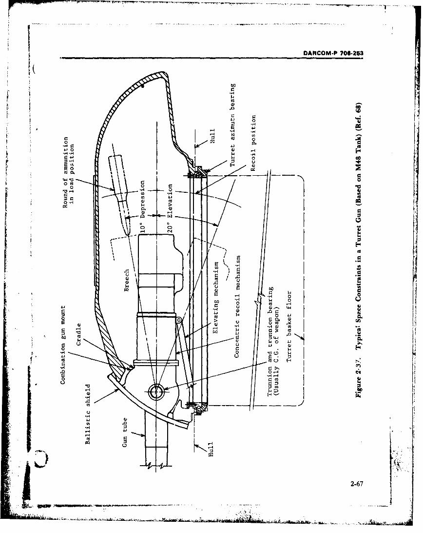
DARCOM-P 706-253
0 0
4J
4-~0 4-10- w @
$44
/ 0-0 " I I
00
CD)
9-44
-IibU p 0
Q) 4
- - 2-670 41qpg~~mr 0~9.I 4~- ----- ___
DARCOM-P 706-253
among the diverse applications (including towed The tank gun must be fully operable to theand self-propelled weapons) is needed, however, maximum required angles of elevation and de-Cannon weight has been found to reasonably pression, which usually range from +20 to -10fulfill this role. Thus, the ratio of breech mecha- deg. Relatively flat-trajectory direct fire is pro-nism weight to cannon weight was found to range vided by the tank weapon system, but the variousfrom 0.217 to 0.447, based on the weapons given attitudes of the vehicle make a substandal quad-in Tables 1-1 and 1-2. rant angle necessary. Gun depression is impor-
Although these data are ,alid for general tant, for example, in situations where the defiladedesign guidance, they should be interpreted in firing position is used but the tank is located on aproper perspective. The weight ratios reflect both slope.old and new designs; the.'efore, they can include Space constraints are more critical with thesubtle changes due to new materials, design, and weapon depressed (Fig. 2-37). Because the guntesting techniques. In future designs, a reliable axis is necessarily close to the turret roof, thebreech that fits below the indicated range would vehicle height limits the amount of depressionnevertheless be welcome. Similarly, a breech-gun possible. The depression angle is limited to thatweight ratio somewhat larger than the cited which allows all the needed mechanism func-"limit" would be acceptable if justified by tions-i.e., loading, recoil, extraction--to takeoffsetting advantages, place. If necessary, a vehicle height is traded off
to provide the required gun depression. TheS2-20 SPACE CONSTRAffNTS qrehms giibreech designer must limit protrusions, e.g., op-
Weapon application and equipment function erating handles, and make sure that all the cor-establish the space constraints on breech design. ners are rounded.For example, freedom of movement through re- In general, similar restrictions apply to thequired gun elevation angles, depression, and maximum elevation angle. There is, as Fig, 2-37traverse all demand space which must be pro- shows, more space between the weapon axis andvided by different means in enclosed turrets. In the turret, however. Elevation is limited to pre-addition, space assignments must consider such vent interference between the bottom of thefunctions as loading, ejection and recoil, the breech ring (or recoil guard) and the parts of theman/machine relationship, and equipment elevating mechanism.maintenance. Traverse does not present serious space prob-
lems. The turret is fully rotatable in azimuth on a2-20.1TURRE GUNSsingle-row ball-bearing assembly (Ref. 69).
Weapons mounted in protective structures Self-propelled artillery with enclosed gunaboard self-propelled vehicles pose special space turrets--e.g., 105 mm and 155 mrr self-pro-problems. Operating space in the tank turret pelled howitzers, M108 and M109 vehicles-particula:ly is limited. Vulnerability require- pose similar space limits on breech cperation.ments dictate that the overall dimensions of a Because of different tactical employment,tank be minimized and, because target height is weapon sophistication, and storage require-considered especially important, a low vehicle sil- menis, however, the space constraints are lesshouette is sought. The shape of the turret, which stringent than for tanks. Also, allowing space tois sloped to deflect projectiles away from the provide maximum elevation and depression isstructure and afford protection, further restricts less of a prcblem in self-propelled weapons.the crew in breech operations. Fig. 2-37 shows Traverse is accomplisht.d as in tank turrets,the limitations of a tank turret that affect breech although the "turret" is not always enclosed, ! ;. , Idesign. e.g., Fig. 1-1, or fully rotatable. (See Table 1-2). ,...a "
2-68
DARCOM-P 706-252
S2-20.2 FWL GUNS environmental conditiens (Ref. 70). Hii tasks
The space constraints associated with field consist of 1,)ading the weapon and otherwise as-guns result from the weapon mount and sup- sisting gun operations. Ideally, loading clear-porting structure. In firing at high quadrant ances, ammunition handlig areas, ard stowageangle where traverse is needed, space con- spaces should accommodate the 5th to %th per-straints are evident. The trails and the breech centile loaaer (see par. 2-22.1 for anthropomet-mechanism in recoil cannot be allowed to inter- tic considerations).fere. This is one reason why towed field pieces In artillery applications a generally greatergenerally have limited traverse c;ipabilities space availability is reflected in the loading task.(Table -I-). The carriage design is more compli- Clearances present a problem only at the highercated when the design requires more traverse. A quadrant angles, but that firing mode is a sub-noteworthy example of this is tne 105 mm Howit- otantial part of weapon employment. For smaller
zer, M102, with 360 deg traverse capability for sized weapons--e.g., the 105 mm howitzer-am-close infantry support. In this case, space limita- munition type, size, and breech space allotmenttion at the breech end of the gun affects both the permit loading up to the design limit of eleva-breech designer and carriage designer. tion. As caliber is increased, both ammunition
The breech designer has limited influence on and weapon factors tend to work against highspace constraints. Equipment envelope dimen- elevation loading. Projectile size and weight re.
sions are usually restrictive and clearance for quire the use of manual or externally poweredbreech mechanism components during actua- assist devices; ammunition type necessitatestion, loading, ejection, and recoil must be con- ramming of th, projectile and separate loading of
sidered. Particular attention must be given to the bagged propellant. A prominent example of anp relationship of the esuipment arid the operating externally powered loader rammer is the device
crew. Human factors involved with turret and used with the 175 mm Gun M113A1/8 in.
breech design are discussed in par. 2-8. Howitzer, M2A2, self-propelled weapon systemr(Fig. 1-1). This hydraulicaily operated imecha-nism typifies the requirements for loading the
2-20.3 LOADING larger nize weapons and also the problems en-The loading of large caliber ammunition poses count-.red therein; the device is detailed in Ref.
certain space problems. Again, these problems 64. Weapon configuration for such calibers doesare considerably more severe in turret-mouted not permit loading at higher elevations althoughguns. Because of the restricted space ii, th' tur- this would be a desirable feature. Actually, theret, the breech mechanism rnust be designed so breech-loader interface is the specific prob!emthat the main armament round can be loaded in area involving both space constraints and thethe minimum space. In most tank applicatinns, need to keep actuating devices simple, Vthis entails the ability to load through the range Accordingly, thc loading procedure calls forfrom +20 deg elevation to -10 deg depression. ibe gun tuoe to be first set at a low elevationThe breech designer should be aware of the prob- which br'ngs the breech recess and ramming"lems of handling ammunition in a cramped tur- trough into ahguir.ent. A projectile is then ram-ret. Applications may arise where the designer med into its seat in the chamber; separate inser-will be involved with load assist cdevices, e.g., lion of the bagged proptllant, closing of the Cloading trays and ramming troughs, and vessibly breechblock. and insertion of the primer car-automatic loaders. The loader has the highest tri'lge complete the ,hading prt-cess. At thiswork rate of any crew member in a vehicle fight- point, the tube can be elevated to the desired fr-ing compartment, and is, therefore, the one most ing position-proper ramming develops enoughlikel.; to be affected by the existing spatial and contact force between the projectile rotating
2-69
DARCOM-P 706-253
band and the start of tube rifling to prevent fall fully emplaced and elevated, a recoil pit must beba-!k in the raised position. The added design dug to ensure proper breech clearance including
S ' complexity of accommodating all gun elevations the limits of traverse (Ref. 71). A pit covering isand the likelihood of having to vary the ramming needed for efficient operation of the piece whenforce have not been justified for the current gen- not engaged in high angle fire.eration of loading mechanisms.
2 . J I2-21 DYNAMIC LOADINGi' 2-20.4 EJECTIONThe spare problems of ejection are minor re- The projectile is accelerated by the force exert-
lative to those of ammunition loading. Withe- ed on its base by the pressure generated by thearate-loading ammunition there are no cartridge burning propellant. To this force, there must b,-cases, and primer cartridge an equal and opposite force exerted against the
breech of the weapon. This reaction force causescreate a space problem. The metal cases for thesmaller caliber ammunition present problems mesm, an ca t uatin m echanismoilonly at high quadrant elevations. If the extrac- forsubjected. The gun design must provide forting mechanism dors not produce full ejection atextreme gun elevations, time and manpower are absorption of these stresses, which in largerequired to remove the spent cartridge, weapons becomes a major problem. The internal
pressure in the chamber applies an axial force ontak bre .The rewstractiondedvine p imsty b the breechblock and a radial force to the chain-b er walls. Whether the breech is the threaded- or
designed to deflect the spent cases downward,rather than sideways or upward, to protect the sliding-wedge type, a combination of radial dis-placement of the chamber wall and high axial
crew. Ejection velocity must be controlled to pre- force can cause serious structural damage or gasvent case rebound into the breech ring or other leakage if not designed for. Inertial loads applieddevices (Ref. 70). The development of consum- during the recoil cycle also act in the axial direc-able case rounds eliminates the case ejection drn h eolcceas c nteaildrcaoblemase rtion. This should be considered in any analysis of
stresses on the threaded members of the breech.
2-20.5 RECOIL Recoil dynamics has been rigorously covered in
The recoil length of a weapon imposes definite the literature (Refs. 72 and 73).space requirements on th-e breech mechanism.The breech de~rigner must confine devices and 2-21.1 PRESSURE
components in a dimensional envelope that is When a charge is ignited, gases develop fromcompatible with the recoil distance. the surfaces of each propellant grain and the
In turret emplacements, the breech mecha- pressure in the chamber rises rapidly. Because ofrism must clear the full recoil distance of the gun friction and resistance of the rotating band (shotthrough the entire quadrant and range from start), the projectile does not move until themaximum elevation to depiession (Fig. 2-37). It pressure behind it reaches from several hundredwill not be possible to use auxw"ary procedures to a few thousand pounds per square inch. Afterfor clearance at the extreme tube positions. motion starts, the pressure continues to rise untilBecause of turret space limitation and the in- (1) the burning area ceases to increase, and (2)creased vehicle mass aiding stability, recoil the volume of the chamber and breech behind thesystems for self-propelled weapon systems are projection reaches the point where the rates ofdesigned for shorter strokes (Tables 1-1 and 1-2). gas generation and volume increase behind theIn some towed field weapons, breech clearance projectile are equal. The projectile acceleratescannot be met by design alone. After the piece is provided there is a net force acting upon it. When
2-70
I;,
DARCOM-P 706-253
the projectile reaches the muzzle, the pressure in- withstand the stresses without rupturing or over-side the tube has fallen to about a tenth to a fifth turning.of the maximum pressure-depending upon the To reduce the carriage stresses to a reasonableexpansion ratio of the cannon. value and to ensure stability, a recoil systemn is in-
Interior ballistics include combustion mode of terposed betweeen the gun and the carriage. Thethe powder, pressure developed, velocity of the recoil system absorbs the energy of the recoilingprojectile along the bore, and the calculation of parts over a certain convenient length, returningthe dimensions of chamber volume for the pow- the gun into position for further firing. Theder which, for any particular design of gun and recoiling parts are the gun and those parts of theprojectile, will give the required muzzle velocity recoil mechanism and carriage which move inSwhile not exceeding the permissible interior pres- recoil and counterrecoil with the gun.sure. The powder-pressure curve is used to de- The higher the resistance offered by the recoiltermine the gun and breech wall thickness brake(s), the shorter will be the total length ofneeded to withstand expected pressures. recoil. The system is usually designed so that
"The greatest interior pressure that a gun may throughout recoil the resistance offered will bewithstand without exceeding the elastic limit of approximately the same at each instant;the metal is known as the "elastic strength however, the resistance may be variable. Sincepressure" which varies along the bore. An the work performed in each case is the same, theal!owancc is made for safety and a curve of "per- value of the constant total resistance will be lessmissible pressure" is established which must not than the maximum value of a varying total resis-be exceeded (Ref. 74). In practice, actual tance. Accordingly, for a given length of recoil,pressures generally lie below this curve. Fig. 2-38 the constant total resistance will produce lessshows these relationships, strain in the carriage.
Seal and obturator design s of great impor- The permissible length of recoil is often limitedtance to assure that the breech will be protected by the dimensions of the carriage, maximum
L from the erosive action of the high-velocity, high- angle of elevation, or other considerations. The
temperature gases developed in the bore under path of recoil must then be limited by applyinghigh pressures. If any passage in the breech is sufficient resistance by the brake to absorb theopen to the gases, they are forced through it. The energy of recoil over that distance.threads and other parts of the breech mecha- The breech designer must provide for attach-nism subject to this gas action are eroded, chan- ment of the recoil mechanism to the breech, andneled, and worn away to such an extent that the design breech operating mechanisms that arebreech mechanism is soon ruined and the gun is compatible with the allowable recoil distancerendered useless. and vehicle envelope. Counterrecoil forces are of-
ten used to activate automatic features of the2-21.2 FORCE breech operational cycle.
The stresses to which a gun carriage is sub- Typical curves showing recoil travel velocityjected are caused by the action of the powder and pressure as functions of time are given in Fig.gases. Since the powder gas pressure is transmit- 2-39.ted equally in all directions, the force tending tomove the gun to the rear is very large- 2-21.3 TEMPERATUREamounting to several million pounds in the major In the brief period of propellant burning and * jcaliber weapons. If the gun were rigidly moun- projectile ejection, the high temperature of the t h
ted, without any recoil system, it would be im- accumulating gases can transmit heat into the iipossible to build a carriage strong enough to bore more rapidly than it can be dissipated.
2-71
- " " , ' -. . . . . -- •. . .•" " " . . . . . .. ... . . . . 7
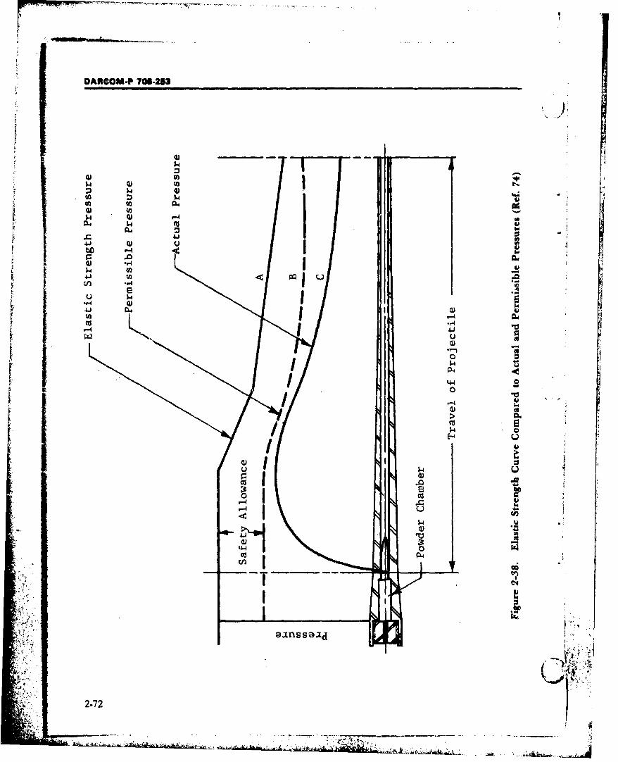
DARCOM-P 708-U53
0) -u
a) '
I~r-4 CIA-4
-P-4
14 0
"r-4 5 h
1.4E
IT0
2-724
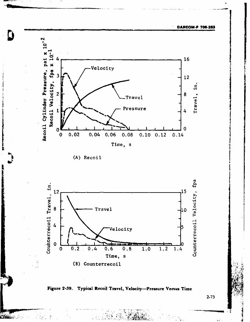
OARCOM-P 70-253
'-4
N .1•,.1 41 . .. .. 16
O44 -Velocity
4 12
S2 "Travel 8 7-4
Pressure $4w~v-44,=4 *"4U o.
o 0a 0 0.02 0.04 0.06 0.08 0. 10 0.12 0.14
Time, s
(A) Recoil
"12 15 -
'4-
Id04 8 Travel -l0
F-4
'-4 - >
J 4 f- r'-Velocity - o
0- '-4I
O 0 0.2 0.4 0.6 0.8 1.0 1.2 1.4
Time, s U
"(B) Counterrecoil
Figure 2-39. Typical Recoil Travel, Velocity-Pressure Versus Time
2-73
S... :" .... ;' :"@ ";"4 " . .' ' ., ,',•!• .":i: 'i'-: ,•;•!:', -' ., ,

DARCOM-P 706-293
There is danger of overheating of the inner sur- be kent simple to meet requirements for reliabil- ,
face metal and consequent flaking of eroded ity and maintainability.
metal particles. If firing is repeated before the
surface metal has cooled sufficiently to regain 2-22.1 HUMAN ENGINEERING
normal strength and wear resistance, the Human engineering is that area of human fac-
weakened metal will be subject to wear by the tors that applies scientific knowledge of human
second projectile, the firing stresses, and an ad- characteristics to the design of items to achieve
ditional increase in temperature. effective man-machine integration and utiliza-
In general. thermal load is not considered a tion (Ref. 76). The capabilities and limitations of
factor in breech design of large caliber weapons the men who serve as crew members are the base-
(Ref. 75). Large bore diameters facilitate heat line for weapon system design. The official Armyloss and the greater barrel thicknesses provide selection procedures are found in AR 611-201
more heat.absorbing metal per unit of bore sur- (Ref. 77) and AR 600.200 (Ref. 78). We will con-
face. As weapon requirements are tending sider some of the aspects of breech design intoward higher firing rates and lighter weights, which human capability plays an important role.thermal loading may become a more significant Manual or semiautomatic breech operationbreech design consideration. modes require that certain functions be perform-
ed by the operator. The following humanengineering related factors, extracted from Ref.
2-22 MAN/MACHINE 79, should be considered in their design:
RELATIONSHIPS 1. Handles, levers, pedals, knobs, wheels, and
The relationship of the crew and breech mech- toggle switches should be designed so that per-
anism during operation and maintenance is of sonnel from the 5th through 95th percentile,
great importance. A number of factors that will wearing Arctic clothing can operate them effect-
increase the effectiveness of this relationship ively.
must be considered in designing the breech 2. All controls should be designed, oriented,
mechanism, i.e.: and located in accordance with normal work-1. To make sure equipment is properly used, habit patterns, customary reaction, and human
it must be designed for a specific user popula- reflexes.
tion. This constraint upon design is an obvious, 3. Stereotyped relationships between controls
although perhaps unconscious, primary consid- and displays should be observed to take advan-
eration of the designer. tage of crew members' previous learning, maxi-
2. Designers must design for men who will, in mize transfer of training, and minimize error. Fortactical situations, be under conditions of stress example, the conventional directions for variousand fatigue from many causes. In the tactical sit- movements listed in Table 2-3 should be recog-uation, there may be a performance decrement nized.that is not caused by any basic inability of the 4. The direction of movement of the control
troops to perform but by the fact that the indi- should be consistent with the movement of thevidual soldier is overloaded both physically and controlled object.
mentally. 5. The most frequently used hand controls
3. Equipment must be designed to be as sim- should be placed between elbow and shoulder
pie as possible to operate, and it should not re- height. Where "blind" reaching is required, the - ,quire intellectual data transformation where per- control should be located forward and slightly
sonnel may be distracted. Equipment should also below shoulder height. (J '*
2-74
*M A _.. . .. . . . . . . . . . . . . . . .
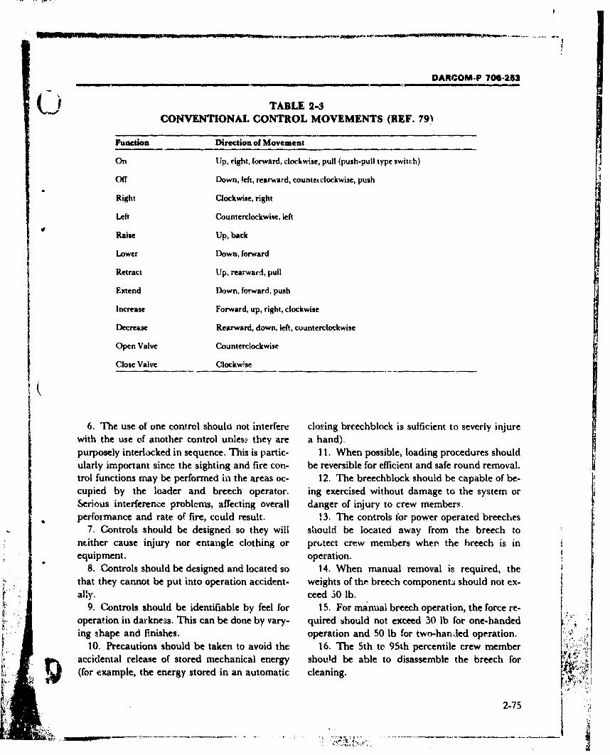
DARCOM-P 706-253
(j TABLE 2-3CONVENTIONAL CONTROL MOVEMENTS (REF. 79)
Function Direction of Movement
On Up, right, forward, clockwise, pull (push-pull type switch)
Off Down, left, rearward, countet clockwise, push
Right Clockwise, right
Left Counterclockwise, left
Raise Up, back
Lower Down, forward
Retract Up, rearward, pull
Extend Down, forward, push
Increase Forward, up, right, clockwise
Decrease Rearward, down, left, counterclockwise
Open Valve Counterclockwise
Close Valve Clockwise
6. The use of one control should not interfere closing brcechblock is sufficient to severly injurewith the use of another control unles.ý they are a hand).purposely interlocked in sequence. This is partic- 11. When possible, loading procedures shouldularly important since the sighting and fire con- be reversible for efficient and safe round removal.trol functions may be performed in the areas oc- 12. The breechblock should be capable of be-cupied by the loader and breech operator. ing exercised without damage to the system orSerious interference problems, affecting overall danger of injury to crew members,performance and rate of fire, could result. 13. The controls for power operated breeches
7. Controls should be designed so they will should be located away from the breech tontither cause injury nor entangle clothing or protect crew members when the breech is inequipment. operation.
8. Controls should be designed and located so 14. When manual removal is required, thethat they cannot be put into operation accident- weights of the breech component. should not ex-ally. ceed 30 lb.
9. Controls should be identifiable by feel for 15. For manual breech operation, the force re-operation in day-kness. This can be done by vary- quired should not exceed 30 lb for one-handeding shape and finishes. operation and 50 lb for two-hanled operation.
10. Precautions should be taken to avoid the 16. The 5th to 95th percentile crew memberaccidental release of stored mechanical energy should be able to disassemble the breech for A
(for example, the energy stored in an automatic cleaning.
2•- 2-75
- ..---
DARCOM-P 706-263
17. Case ejection should not endanger per- 5. When the task must be repeated frequently, )sonnel or equipment. e.g., many times on a given day.
18. The breech should be designed to provide The forces that can be exerted by 95% of thedrains to preclude the trapping of cleaning fluids male personnel are listed in Fig. 2-41 in terms ofand water. the direction of movement and the body member
The Army Human Engineering Laboratories used.have compiled a large body of data on all aspects All operating positions should allow freedomof human factors, both physical and psychologi- to move the trunk of the body. When large forcescal. This information should be studied by the (in excess of 30 lb) or large control displace-breech mechanism designer (see biographical ments (in excess of 15 in. in a fore-aft direction)listings). are required, the operator should be provided
with sufficient space to move his entire body.2-22.2 OPERATING EFFORTS AND Table 2-4 shows the ranges for each type of
RANGE OF MOTION voluntary movement possible at the joints. TheThe maximum amount of force or resistance designer must keep in mind that these ranges are
that can be designed into a control should be for nude persons, and thus, do not allow for thedetermined by the greatest amount of force that restrictions imposed by clothing. If the range ofcan be exerted by the weakest person likely to voluntary movement is used as a direct functionoperate it. The maximum force that can be ap- in operating or maintaining the equipment, theplied will depend on such factors as the type of maximum allowable angular value should be thecontrol, the body memrber being used to operate lower-limit value. This allows 90% of the popu-r the control, the position of this member during lation, i.e., 1.3 standard deviations below the "operation, the general position of the bodcy, and mean value, to perform the voluntary move- J •whether or not support (e.g., back rests) is ment. If the range of voluntary movement is usedprovided, to design for body freedom of movement, then the
Maintenance requirements become more com- upper-limit angle should be used.plicated when special tools and lifting equip-ment are required. Whenever possible, equip- 2-23 SAFETYment should be designed to be lifted by one man. Saferty for both the crew and the weapon areTwo men may be required to perform certain necessary. Requirements for safety in militarylifting tasks, e.g., removing the breechblock of a combat situations are not comparable to those155 mm weapon, but this is not normally desir- for industrial safety, but nevertheless they exist.able. Leg muscles, rather than arm or back mus- Since the operating crew of a gun works in closecles, should accomplish heavy lifting. The ap- proximity to the equipment during all of the op-proximate safe lifting capacity of one man is erations, its members must be protected from in-shown in Fig. 2-40. These values should be re- jury so they can continue to perform their work.duced considerably under the following condi& The use of safety interlocks, guards, and the care-tions: ful placement of parts and mechanisms reduce
1. When the object is very difficult to handle; the possibility of accidents or injuries. However,e.g., bulky, slippery design safety must be accomplished without ad-
2. When access and work space are less than verse results on weapon effectiveness or opera-optimum tion. Prevention of equipment breakdown is also
3. When the force required must be coninu-- a protcction for the personnel in a combat situa-ously exerted for more than 1 min tion.'
4. When the object must be finely positioned Locking devices are also needed to prevent un-or delicately handled intenf'onal firing and to keep breech operation in2-76
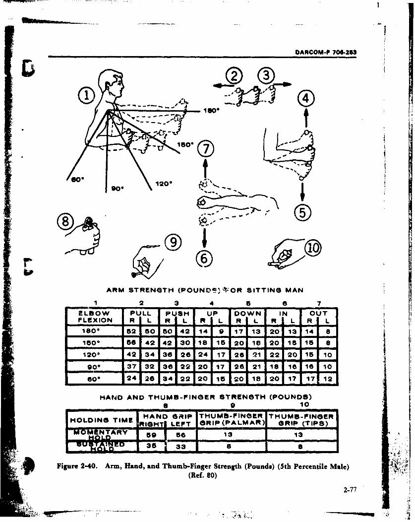
DARCOM-P 706-253
S~180"
9 0 120o -.
-- aa
ARM STRENGTH (POUND0kVýOR SITTING MAN
12 3 4 58 7
ELBOW PULL PUSH UP DOWN IN OUTFLEXION R I-L R L R ITL R L R L R L L
1800 52150 50 42 14 9 17 13 20 13 141 8
1500 56142 42 30 18 15 20 18.20 15 15 8P1200 4234 3826 24 171262122 20 1510
9900 37 32 36 22 201 621 18 1 a1 10
-Arm, - -d- and
600 24 26 34 22 201 018 20 11712
HAND AND THUMB-FINGER STRENGTH (POUNDS)(ef.0) 10HHAND GRIP THUMB-FINGER THUMB-FINGERHODN IERIGHT LEFT G5RIP (PALM AR) GRIP (TIPS)
OMNTARY 5 5613 13
Figure 2-40. Arm, Hand, and Thumb-Finger Strength (Pounds) (5th Percentile Male)3K
2-77
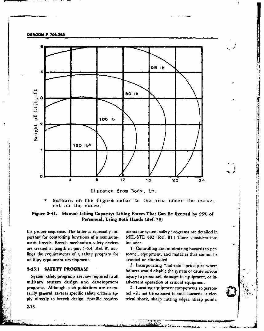
DARCOM-P 70S-263
4 - - I i lI Injn
4.
44• 50 lb •
44I
944,_10 100 1b
2AI
4 12 18 20 24o ., i ",
Distance from Body, in.
* Numbers on the figure refer to the area under the curve,not on the curve.
Figure 2-41. Manual Lifting Capacity: Lifting Forces That Can Be Exerted by 95% of
Personnel, Using Both Hands (Ref. 79)
" the proper sequence. Ile latter is especially im- ments for system safety programs are detailed inportant for controlling functions of a nemiauto- MIL-STD 882 (Ref. 81.) These considerations~imatic breech. Breech mechanism safety devices include: 81 ss
are treated at length in par. 1-6.4. Ref. 81 out- 1. Controlling and minimizing hazards to per-lines the requirements of a safety program for sonnel, equipment, and material that cannot bemilitary equipment development, avoided or eliminated
2. Incorporating "fail-safe" principles where2-23.1 SAFETY PROGRAM failures would disable the system or cause serious
System safety programs are now required in all injury to personnel, damage to equipment, or in-military system design and development advertent operation of critical equipmentprograms. Although such guidelines are neces- 3. Locating equipment components so person- 0sarily general, several specific safety criteria ap- nel will not be exposed to such hazards as elec-ply directly to breech design. Specific require- trical shock, sharp cutting edges, sharp points,
2-78
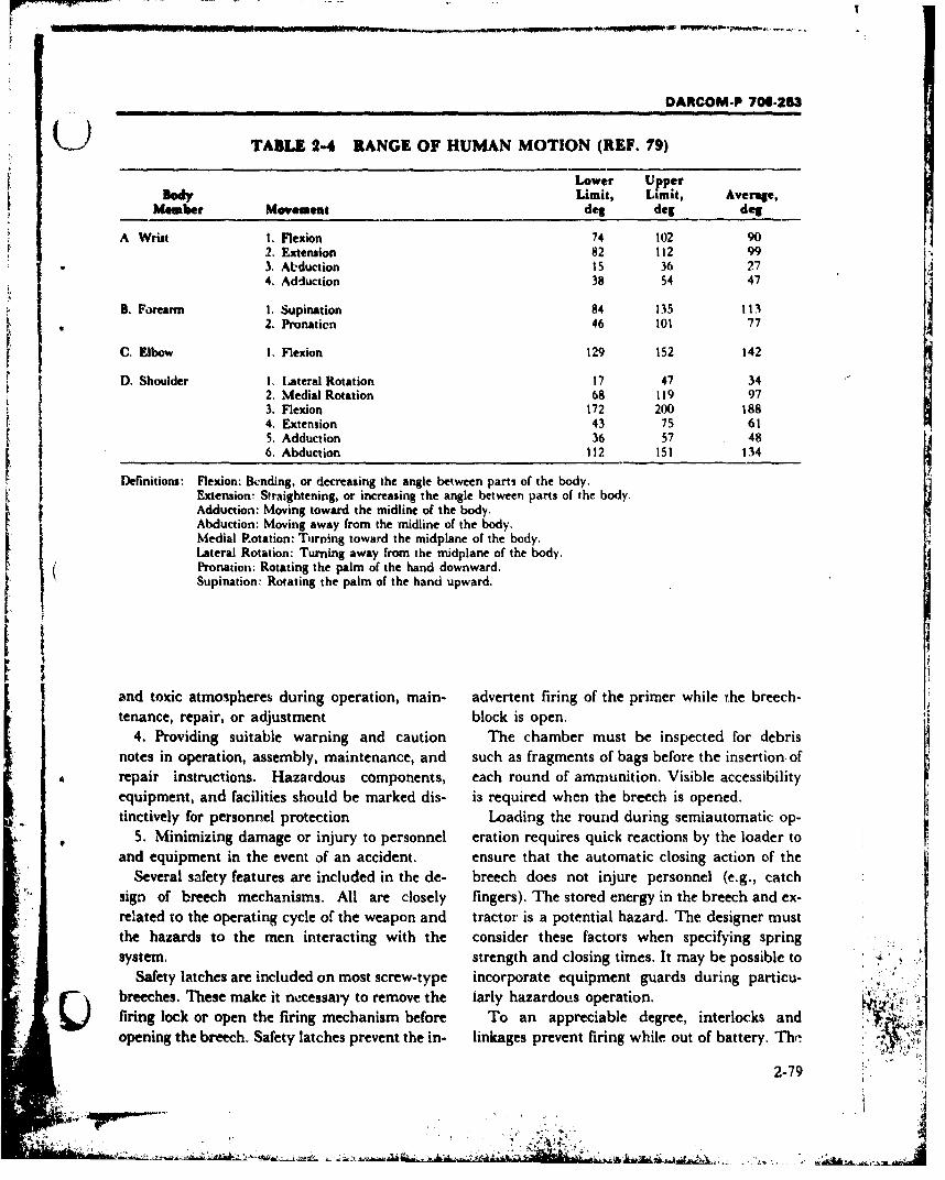
i , . • • •7•• • • . . . ..-.. . -.
DARCOM-P 706-263
(9 TABLE 2-4 RANGE OF HUMAN MOTION (REF. 79)
Lower UpperDody Limit, Limit, Average,
Member Movement deg deg deg
A Wrist I. Flexion 74 102 902. Extension 82 112 993. Abduction Is 36 274. Adduction 38 54 47
B. Forearm I. Supination 84 135 113D. Pronation 46 101 77
C. Elbow 1. Flexion 129 152 142
D. Shoulder 1. Lateral Rotation 17 47 34
2. Medial Rotation 68 119 973. Flexion 172 200 1884. Extension 43 75 615. Adduction 36 57 486. Abduction 112 151 134
Definitions: Flexion: Blnding, or decreasing the angle between parts of the body.Extension: Straightening, or increasing the angle between parts of the body.Adduction: Moving toward the midline of the body,Abduction: Moving away from the midline of the body.Medial Rotation: Turning toward the midplane of the body.Lateral Rotation: Turning away from the midplane of the body.Pronation: Rotating the palm of the hand downward.Supination: Rotating the palm of the hand upward.
ri
and toxic atmospheres during operation, main- advertent firing of the primer while the breech-tenance, repair, or adjustment block is open. I,
4. Providing suitable warning and caution The chamber must be inspected for debris
notes in operation, assembly, maintenance, and such as fragments of bags before the insertion ofrepair instructions. Hazardous components, each round of ammunition. Visible accessibilityequipment, and facilities should be marked dis- is required when the breech is opened.tinctively for personnel protection Loading the round during semiautomatic op-
5. Minimizing damage or injury to personnel eration requires quick reactions by the loader toand equipment in the event of an accident. ensure that the automatic closing action of the
Several safety features are included in the de- breech does not injure personnel (e.g., catchsign of breech mechanisms. All are closely fingers). The stored energy in the breech and cx-related to the operating cycle of the weapon and tractor is a potential hazard. The designer mustthe hazards to the men interacting with the consider these factors when specifying springsystem. strength and closing times. It may be possible to
Safety latches are included on most screw-type incorporate equipment guards during particu-breeches. These make it necessary to remove the iarly hazardous operation.
Slock or open the firing mechanism before To an appreciable degree, interlocks andopening the breech. Safety latches prevent the in- linkages prevent firing while out of battery. Th-r'
2-79

DARCOM-P 706-253
inability of a gun to return to battery is an indi- sories, and +125* to -65"F with specialized aidscation of a fault in the recoil mechanism or an in- in kit form.terference with the gun movement. The natural and induced envir-'nments are im-
portant to the military because of their effects on2-22.2 MALFUNCTIONS men, material, and operations. Principal effects
and types of failures induced by various environ-The prevention of malfunction is considered in an typ s aresuinduced by vario2s enr
detail in par. 3-15. Even the best designed breech factors are of primary importance to the breechwill malfunction througlA no fault of the breech orfiring niechaniss'n design. The breech also must designer. Also listed in Table 2-5 are typical cri-
teria for the transport phase of weapon opera-be designed to facilitate extraction of misfired tional life. As is often the case, the transport ofrounds. It is critival that the designer be aware of
the procedures 'used when malfunctions occur equipment induces a more severe environment on
and that he design the eqvipment to accommo- the weapon than its operational environment.andeo that man sourign from whichmn an accomodate the safe removal of misfired rounds. Figs. 2- There are many sources from which an envi-42 to 2-44 outline possible malfunction condi- ronmental engineei can obtain reliable data con-tioos and the appropriate actions to be followed cerning the environment or environniental fac-in the various contingencies, tors to which equipment will be subjected, for ex-ample, Refs. 82, 83, 84, and 85. These data are to
be found frequently in military regulations,standards, and specifications. It is not unusual,
Sand, dust, heat, humidity, ice, snow, rain, however, for the designer to feel that none of theand exposure to .,alt water are climatic factors specific eawironmental parameters is suitable forthat effect the "ireech. It is important to recog- his needs. ' -nize and evaluate the effects such faktors will The designer must be aware of the needs of thehave and how these effects can be controlled, end item user and of the complete environment
AR 70-38, Ref. 82, recognizes four brond types which his item will face from "stockpile toof climate subdivided into eight categories: target". He may often prepare an environmental
envelope for his item of materiel, examples ofTic Cltmatic which are shown in Table 2-5.Typ_... C~ategory
A. Hot-dry 1. Hot-dry 2-25 RELIABILITY, AVAILABILITY,2. Wet-warm MAINTAINABILITY, AND
B. Hot-wet 3. Wet-hot DURABILITY (RAM-D)4. Humid-hot
Coastal Desert Weapon design has always considered, im-5. Intermediate plicitly, these four characteristics to be impor-
tant. However, they have been recently reem-C. Intermediate Hot-dry phasized; and these categories now form an inte-
6. Intermediate gral part of design requirements set forth for aCold
7. Cold given piece of materiel,D. Cold 8Each category is distinct from the others. Re-liability is a probabilistic quality and relates to
AR-70-38 requires the material developed to functional aspects of breech systems. Availabili-be capable of acceptable performance through- ty refers to the concept of whether an item will beout the ambient range of +1100 to -25 0 F with ready (available) when it is needed. Maintain-no aids or assistance other than standard acces- ability refers to the concept of being able easily to
2-80"4, p • •, •, .;.• •T • - ' ' •" - ,
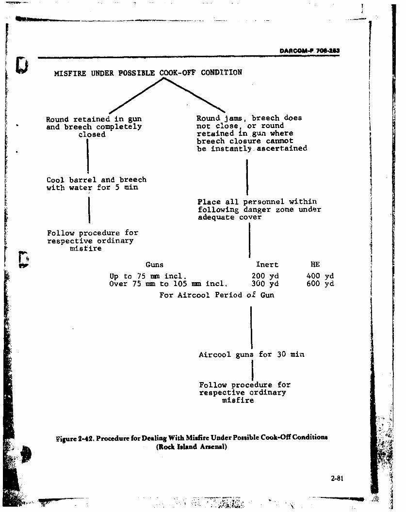
0"COMU-P. 700-25
MISFIRE UNDER POSSIBLE COOK-OFF CONDITION
Round retained in gun Round jams, breech doesand breech completely not close, or round
closed retained in gun wherej breech closure cannotbe instantly ascertained
Cool barrel and breechwith water for 5 min
Place all personnel withinfollowing danger zone underadequate cover
Follow procedure for arespective ordinary
misfireGuns Inert HE
Up to 75 mm incl. 200 yd 400 ydOver 75 mm. to 105 mm incl. 300 yd 600 yd
For Aircool Period of Gun
Aircool guns for 30 minIFollow procedure forrespective ordinary
misfire
Vigure 2-42. Procedure for Dealing With Misfire Under Possible Cook-Off Conditions* ,(Rock Island Arsenal)
4
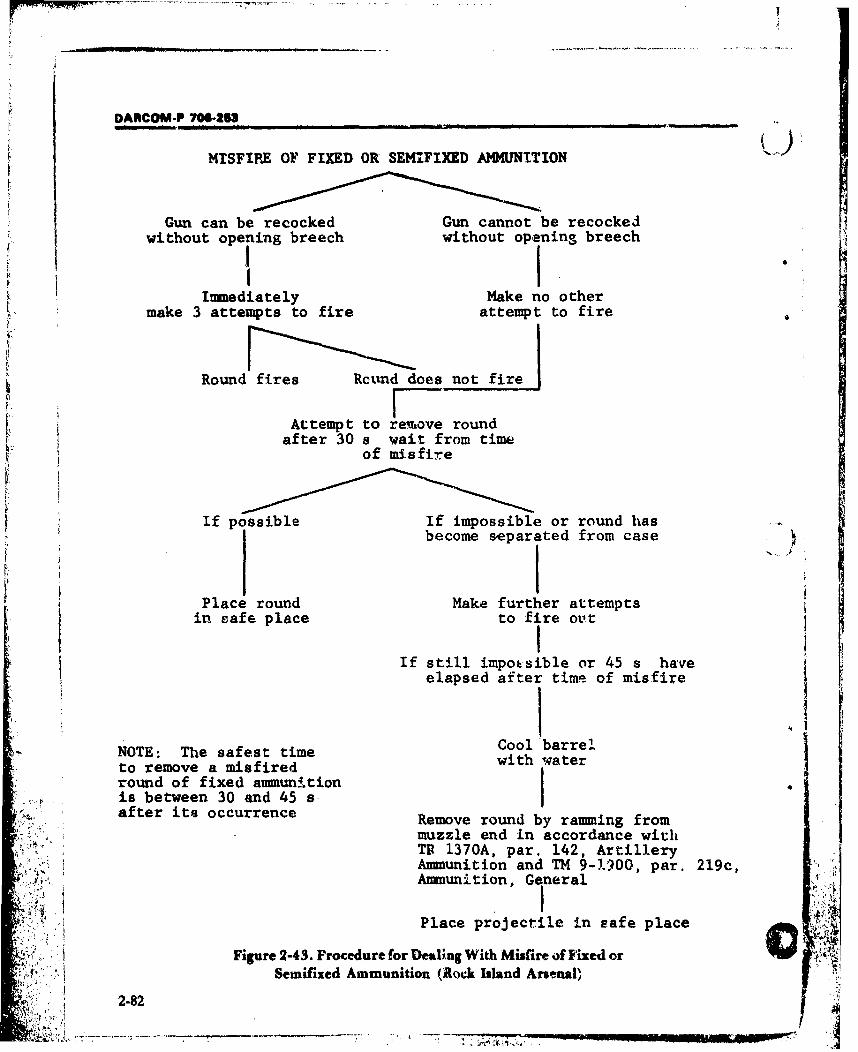
DAIRCOM-P 70.-253
MISFIRE OF FIXED OR SEMIFIXED AMMUNITION
Gun can be recocked Gun cannot be recocked
without opening breech without opening breech
Immediately Make no othermake 3 attempts to fire attempt to fire
Fg
Round fires Rcund does not firerAttempt to re.move round
after 30 s wait from timeof misfire
If possible If impossible or round hasbecome separated from case
Place round Make further attemptsin safe place to fire out
If still impossible or 45 s haveelapsed after time of misfire
Cool barrel.NOTE: The safest time with water-to remove a misfired wround of fixed ammunitionis between 30 and 45 s,after its occurrence Remove round by ramming from
muzzle end in accordance withý.A TR 1370A, par. 142, ArtilleryAmmunition and TM 9-1900, par. 219c,Ammunition, General
Place projectile in safe place
Figure 2-43. Procedure for Dealing With Misfire of Fixed orSemifixed Ammunition (Rock Island Arsenal)
2-82
-:, 1. + •
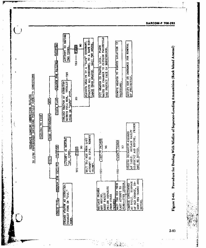
(~.) DARCOM-P 700-253
I-k
0ý011. -
Z4
aa!H z
~ ! ~V
ý -
44
1, go
Z-- E-'2 f a
A w
2-83
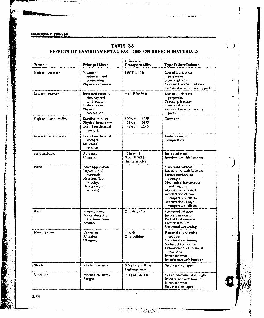
I.
DARCOM-P -7M2U5
TABLE 2-5EFFECTS OF ENVIRONMENTAL FACTORS ON BREECH MATERIALS
Criteria for?actor _ __ Principal Effect Transportability Type Failure Induced
High temperature Viscosity 120*F for 3 h Loss of lubricationreduction and propertiesevaporation Structural failure
Physical expansion Increased mechanical stressIncreased wear on moving parts
Low temperature Increased viscositv -10° F for 36 h Loss of lubricationviscosity and propertiessolidification Cracking, fracture
Embrittlement Structural failurePhysical Increased wear on moving
contraction parts
High relative humidity Swelling, rupture 100% at - 100F CorrosionPhysical breakdown 95% at 950 FLoss of mechanical 45% at 120OF
strengthLow relative humidity Loss of mechanical Embtittlement
svrerngth CompressionStructural
collapse
Sand and dust Abrasion 45 kt wind Increased wearCiogging 0.001-0.062 in. Interference with function
diam particles
Wind Force application Structural collapseDeposition of Interference with function
materials Loss of mechanicalHeat loss (low strength
velocity) Mechanical interferenceHeatgain (high and clogging
velocity) Abrasion acceleratedAcceleration of low-
temperature effectsAcceleration of high-
temperature effectsRain Physical stres- 2 in./h for I h Structural collapse
Water absorption Increase in weightand immersion Partial heat removal
Erosion Electrical failureStructural weakening
WBowina snow Corrosion 1 in./h Removal of protectiveAbrasion 2 in. buildup coatingsClogging Structural weakening
Surface deteriorationEnhancement of chemical
reactionsIncreased wearInterference with function
Shock Mechknical stress 3.5 g for 25-50 ms Structural collapseH-alf.sine wave
Vibration Mechanical stress ± I g at 1-60 Hz Loss of mechanical str-.ngth TFatigive Interference with function
Increased wearStructural collapse
2-84
Z.
DARCOM-P 706-253
S maintain an item. It is distinguished from main- equipment must be designed to last a reasonabletenance which id the physical act of maintaining length of time.an item. Durability generally refers to the con- Reliability is enhanced by good design prac-cept of being usable (durable) for a long period of tice and by cognizance of maintenance require-time until the item is not worth maintaining any ments. As presented in par. 2-25.2, design forlonger; it is a special case of reliability-see par. maintainability and the establishmnent of realis-4-5.2 for further discussion. tic maintenance schedules will maintain the reli-
ability of the breech mechanism. Proper parts di-
2-25.1 RELIABILITY vision and the use of easily accessible wear in-
Reliability is the probability that the breech serts are examples of maintainability design fea- Iperforms all of its required functions under stated tures which, under a proper inspection andconditions for a stated period of time. The basic maintenance schedule, can maintain the reli-quantitative reliability indicator of a given device ability, designed into the breech mechanism.is considered to be the average mean time be-tween trouble-free operation from the correction 2-25.2 MAINTAINABILITY
of one malfunction failure to the appearance of Maintainability is a characteristic of designthe next (MTBF). To a certain extent, operating and installation which is expressed as the proba-reliability of a weapon depends upon its com- bility that an item will be retained in or restoredplexity. The more complex the design-and the to a specified condition within a given period ofmore devices, assemblies, and mechanisms there time, when the maintenance is performed in ac-are in it-the greater is the probability that fail- cordance with prescribed procedures and re-ures will occur from time to~ time. sources. Accordingly, maintainability is con-
A high degree of reliability is of course very im.- trolled by the designer. Despite the best efforts ofportant in guns. Failure of a minor component the logistic system, too often poorly designedcan make an entire weapon inoperative under equipment compounds the maintenance prob-
circumstances where neither time nor reptace- 1cm. Accordingly, a tenet for design engineersment parts is available to the crew in action. Of might be: "If we can't design equipment to lastcourse, under ideal operating conditions, a stock forever, let us at least design it so we can keep itof replacement parts is kept available; but even if going as long as possible, and so we can fix it in athis ideal is achieved, the facts still remain that hurry when we need to, with the men availablethere is an interruption in weapon availability, and the tools available" (Ref. 86).and time and labor are required to perform Maintenance enables the equipment to be
repairs. As practicable in design, reliability can restored and kept in operation with minimum ef-be increased by the use of redundant or "back- fort. Repairs must be infrequent and proceduresup" components. For example, a manually op- must be kept convenient, otherwise the weaponcrating device is provided to back up a breech op.. becomes impractical and its cost becomes too
crating in the semiautomatic mode in the event it high for justification. If repairs take too long, thefails. availability of the weapon is reduced. T~he goal,
Durability, of course, is important in order to of course, is replaceable and easily accessiblejustify the total investment. As mentioned in par. components. These subjects are treated further2-17, the military environment is harsh and is in Chapters 3 and 4.particularly demanding for a breech. In contrast Design engineers engaged in the developmentwith some other weapon operations (adjustment of weapon systems should be concerned with thc.of traverse, adjustment of elevation, etc.), the following objectives:
F breech has to operate each time a round of am- 1. Reducing the frequency of preventivemunition is fired. Under these conditions, the (cyclic) maintenance: Reliability improvements
2-85
DARCOM-P 706-253
will often save time and manpower by reducing system when designing such components as thethe frequency of the preventive maintenance cy- firing pin assembly and the obturating ring.cle. This also allows more operational time for Access is additionally complicated by thethe component concerned, limited space in which to make repairs and the
2. Improving maintainability to reduce down- simple tools available to the crew. The designertime: Test and repair procedures must be sim- must consider these limits and those imposed byplified to reduce the time required to locate and personnel protective equipment such as Arcticcorrect faults by providing ease of access and gloves.simplification of adjustments and repair. Where it is possible and practical without the
3. Reducing the requirements for highly degradation of performance or reduction oftrained specialists: This can be accomplished by maintainability or re.liability, equipment shouldsimplifying the operation and equipment main- be designed with the minimum number of sizes,tenance. types, and components or parts that must be
Factors that affect ease of maintenance in- replaced. Standard fasteners (nuts, bolts, retain-clude: ing rings) should be used when possible. Parts re-
1. Simplicity quiring frequent servicing or replacement should2. Accessibility be interchangeable with similar parts in other3. Interchangeability. units. Like assemblies, subassemblies, and re-Simplification, although the most difficult cri- placeable parts should be designed according to
terion of any design, is the most productive. Sim- MIL, AN, or MS standards, where these are ap-plification can transform a complex monstrosity plicable. A more explanative treatment of main-into a piece of working equipment. The essential tainability is provided in AMCP 706-134 (Ref.functions of the equipment should be incorpor- 87).ated into the design, using the minimum numberof parts consistent with good design practice and! 2-26 PRODUCIBILITYuse criteria. In addition to simplifying normaloperation, preventive and corrective mainte- In simple terms, to make a design produciblenance should be simplified whenever possible. requires a comprehension of:Only reduction in downtime will increase the 1. The specific end use of the equipment oravailability of a weapon system. mechanism
Inaccessibility is a prime maintenance prob- 2. How to makc if efficiently and economical-lem. The mechanic (technician) will tend to ly.
- delay or omit maintenance actions, make mis- The first item influences the selection oftakes, and accidentally damage equipment he materials; while the second involves the choice ofcannot adequately see, reach, and manipulate. manufacturing processes.The greater the number of accessory steps and With few exceptions, breech design must bethe amount of discomfort involved, the more practical in the light of manufacturing capabili-readily the technician/mechanic will perform ty at the time of consideration. It is possible toother less demanding tasks. Periodic n.ainte- design a breech and not be able to have it manu-nance activities such as checks, adjustments, and factured (i.e., not without a great deal of manu-troubleshooting in inaccessible locations may be facturing research and development). Obviously, - - -
unduly postponed or neglected entirely, such a design does not meet the requirementRapid, easy replacement of critical parts under "practical". Producibility considerations enter
the pressures of combat situations is essential. into examples of breech components cited in Sec-The breech designer must give special attention tion III of this chapter (e.g., extracting mecha-to the working environment of the weapon nisms, par. 2-13).
2.86 1
DARCOM-P 706-253
Production processes yield the maximum The pitch of the threads is such that under the
economic effect when the design itself is efficient. force of the propellant pressure inside the chain-This is achieved by minimizing the number of btr, friction will prevent the locked breechblockparts, simplifying their shapes, and prescribing from rotating and opening except when it is un-only the precision and the finishing required by locked and a force is exerted by the operatingthe conditions under which a device will oper- mechanism. The operating mechanism also pre-ate. A most important point to be emphasized is vents further rotation of the block when thethat, if possible, a design should be adopted breech is open, and maintains proper alignmentwhich is not limited to only one particular man- between the threaded sectors. Clearance chan-ufacturing method. nels always are maintained as the block is in-
The designer must also be aware of the even- serted and removed from the recess. In additiontual constraints of his design-such as meeting to the machining operation just mentioned, suit-production schedules, material procurement able clearance cuts are made in both the breech-(possibly involving conservation of rmaterial), and block and ring of the interrupted-screw thread toproduction costs. A more comprehensive discus- permit the block to move into and out of thesion of producibility takes place in Chapter 4, in- chamber opening on its hinged mounting.cluding coverage of production planning and The advantages of the interrupted-screwstandardization. breech are strength, more uniform distribution of
the longitudinal stresses, and relative ease of ob-
turation. Several variations of this type ofS2-27 THREAD CONNECTIONS threading exist, namely:Threaded connections occur frequently in 1. Single-cut threads (the simplest form)
breech mechanism design. They are particularly 2. Conical-taper threads (Bofors)used to: 3. Stepped threads (Welin).
1. Fasten the gun tube to the breech ring. Information ,n their characteristics is pro-2. Lock the breechblock to the ring. vided in par. 1-6.1 and Fig. 1-7. With respect to3. Hold the firing mechanism assembly in the the simplest form of interrupted-thread, it is rec-
breechblock. ognized that the introduction of clearance chan-Interrupted A.uads are used on the breechblock nels necessitates an increased length of threadedand frequen -. irc used o-- the gun tube to allow engagement surface in order to restore the origi-rapid b,- 7'?. '- aiige nal strength value. This demand is alleviated
Interrn -.' threads in the simplest form are somewhat by the techniques employed in themanufactui zd similarly to continuous complete other two variations. The conical taper is an im-threads, except that the mating surfaces are ma- provement, but it requires some retraction for thechined to remove half the threads around the cir- hinge action and there is more difficulty in fabri-cumference. The circumference is first divided cation. The stepped-thread principle cnables ainto an even number of segments. The threads larger diameter and resultant shorter block forare removed in alternate segments, and the two the same surface engagement as the single-cut.surfaces are mated in their ,I-eaded and Since the stepped-thread design permits moremachined arcas. c ...y ;- bormed by than 50% of the breechblock surface to be usedbringing the threads of one surface through the for thread engagement, the angle of turning formachined segments of the other and then locking and unlocking is decreased.rotating one piece a fractional turn to obtain The thread forms generally used for thefull engagement of the threade' -- !as. The threaded connections are acme, buttress, andamount of rotation is the recipror- he num- square threads. The latter two are the most oftenber of segments in each piece. used in small arms. The tooth profiles of these
2-87A _.. . . i:1••:, : ' m,•, i
DARCOM-P 706-253
basic thread types are shown in Fig. 2-45(A). 2. The breech mechanism design staff at ..
The maximum load on these threads is based on Watervliet Arsenal, Watervliet, NY, (or the re-the maximum propellant gas pressure and the sponsible Army agency) be consulted in regardrear chamber area for separately loaded ammu- to material selection--especially for the criticalnition, and on the internal area of the base of the components, e.g., breech ring and breechblock.cartridge case for fixed ammunition. Each military weapon system is provided with
Threads should never be used to align and a technical data package which includes a list ofposition a component during assembly. Wear specifications. Table 2-7 presents such a listresulting from continued takedown and reas- prepared for Cannon, 155 mm, Howitzer,sembly, and local failure at the entering end will XM199 (July 1976) (Ref. 91). It may be notedadvance the travel of the threaded joint at each that of the 66 specifications listed, some 44 aretightening. Continued alignment and position- directly related to materials (25), material in-ing can be assured by machining off the incom- spection (7), and protective finish (12). Probablyplete thread so that the two mating pieces the greatest number of breech parts are coveredmutually (Ref. 88) butt against finished surfaces, by FED STD. No. 66, Steel: Chemical Compositionand by providing sleeve contact (Fig. 2-45(B)). and Hardenability (Ref. 92). MIL-R-10185, Rings,The pressure and force acting on the breech were Breech, Steel Forgings For (Ref. 93) and MIL-S-described in par. 2-21 and a sample analysis of a 500, Steel, Chrome-Nickel-Molybdenum, Bars and
threaded connection is presented in par. 3-17.7. Reforging Steel (for the breechblock body) (Ref.Large caliber artillery are frequently designed 94) are also key steel specifications.
using the thread profiles described in Table 2-6 Materials are chosen for critical parts basedand Fig. 2-46. These threads employ a 20-deg upon having a high fracture temperature, goodpressure angle on the face and have proved to be ductibility, and exhibiting ductile fractures. High ..
capable of extended life. Whenever possible, strength, light weight, and long fatigue life arethreads should be designed according to Refs. 89 also very important characteristics. Breechblockand 90. Part I of this reference presents stan- bodies are fabricated from AISI E4340 steel perdards for the more common thread forms and MIL-S-5000 (Ref. 94). Breech ring bodies are
Part II for acme, buttress, and square forms. made from alloy steel per MIL-R-50185 (Ref.93). Many of the smaller breech mechanism im-portant parts are made from alloy steel per FED
2-28 MATERIAL SELECTION STD. No. 66 (Ref. 92). Extractors are made from
Material selection is an important aspect of the steel 0.23 C (carbon) maximum (with protectivetotal design procedure. Par 1-8.3 introduced ma- finish type 1, phosphate, MIL-P-16232, (Ref.terial selection and additional narration is 95)). Cover plates are made similarly but with upprovided by pars. 3-8 and 4-10.2. As indicated, to 0.34 C maximum. Levers, stops, and bracketsmaterial selection is a highly specialized process are made with 0.38 to 0.53 C while cranks use ain many cases. The entire design team should maximum of 0.50 C. C ranges in alloy steel fromparticipate jointly. The material specialist should 0.28 to 0.50 are used for pins, shafts, and adjust-not make the material selection by himself. The ers. Forged breech ring brackets are also mademost cogent recommendations for material se- with this range of carbon. Parts with 0.5 in. thicklection are that: sections and good allowance or those I in. thick
1. Material used in like parts in previous with less allowance are specified with 0.28 Cdesigns be screened carefully for applications in a minimum and 0.34 C maximum. Thick sections .•;new design. are more difficult to harden reliably in the center
2-88
4-:Ad
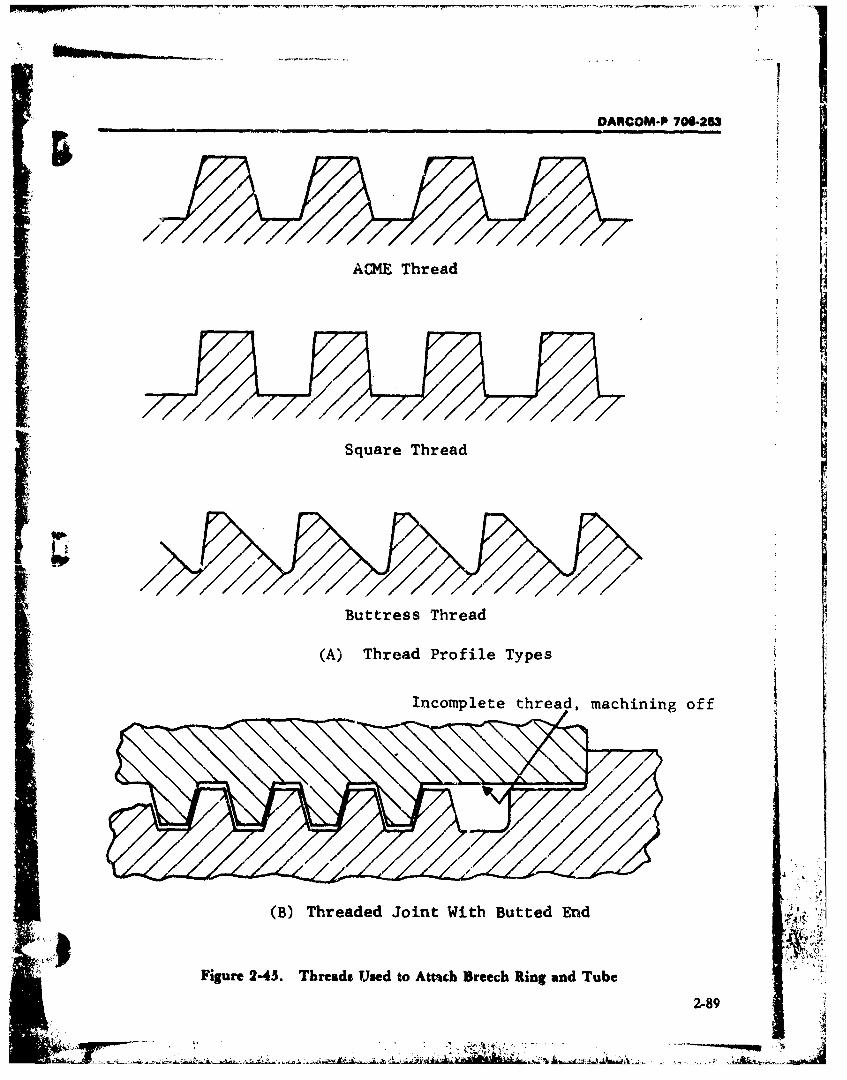
jiDARCOM-P 706-253
l'1
ACME Thread I
Square Thread
Buttress Thread
(A) Thread Profile Types
Incomplete thread, machining off
(B) Threaded Joint With Butted End
Figure 2-45. Thread* Used to Awa~ch Breech Ring and Tube
2-89tJ¶
|a t
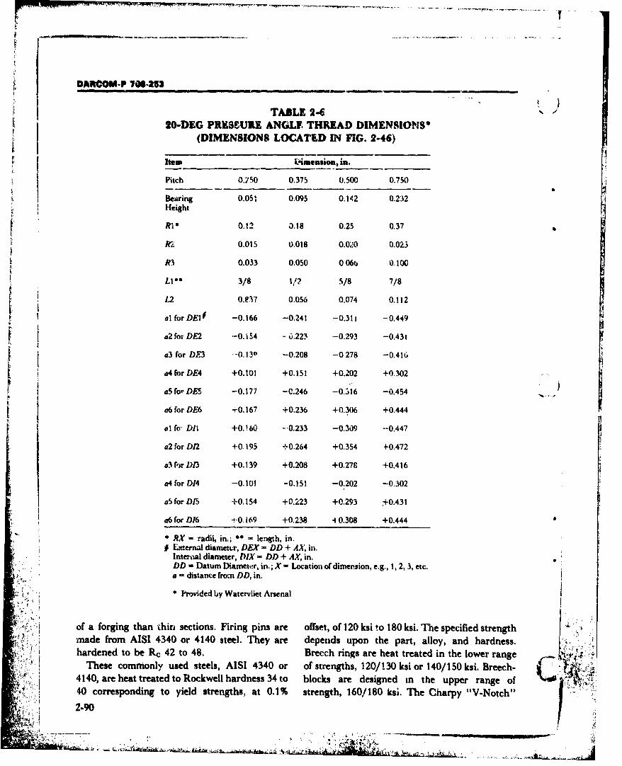
DAR11COM-P 706-253
TABLE 2-620-DEG PRESeUIE ANGLE THREAD DIMENSIONS*
(DIMENSIONS LOCATED IN FIG. 2-46)
Item _dimension, in.
Pitch 0.150 0.375 0.500 0.750
Bearing 0.05: 0.095 0.142 0.232Height
R1 0.12 3.18 0.25 0.37
ir2 0.015 0.018 0.0.'0 0.023
R3 0.033 0.050 0 060 0.100
L1 3/8 1/ 5/8 7/8
1,2 0.Y17 0.056 0.074 0.112
al for DE10 -0.166 -0.241 -0.311 -0.449
a2 for DE2 -0.154 - 0.223 -0.293 -0.431
a3 for DE3 --0.130 -0.208 -0278 -0.416
a4 for DE4 +0.101 +0.151 +0.202 +0.302
a5 for DES -0.177 -C.246 -0.316 -0.454
a6 for DE6 -0.167 +0.236 +0.306 +0.444
al fo Dl1 +0.160 -.0.233 -0.309 --0,447
a2 for D12 +0.195 +0.264 +0.354 -0.472
a3 fr D3 +0.139 +0.208 +0.279 +0.416
a4 for D14 -0.101 -0.151 -0.202 -0.302
aS for D/5 +0.154 +0.223 +0.293 +0.431
a6 for D16 -+0.169 +0.238 40.308 +0.444
RX - radii, in.; * = length, in.E Lxternal diametmr, DEX - DD + AX, in.Interaal diameter, DIX - DD + AX, in.DD = Datum Diameter, in.; X - Location of dimension, e.g., 1, 2, 3, etc.a - distance from DD, in,
S* Prvided by Watervliet Arsenal
of a forging than thin sections. Firing pins are offset, of 120 ksi to 180 ksi. The specified strengthmade from AISI 4340 or 4140 steel. They are depends upon the part, alloy, and hardness.hardened to be Rc 42 to 48. Brecch rings are heat treated in the lower range
These commonly used steels, AISI 4340 or of strengths, 120/130 ksi or 140/150 ksi. Breech-4140, are heat treated to Rockwell hardness 34 to blocks are designed in the upper range of X•,40 corresponding to yield strengths, at 0.1% strength, 160/180 ksi. The Charpy "V-Notch"
2.90
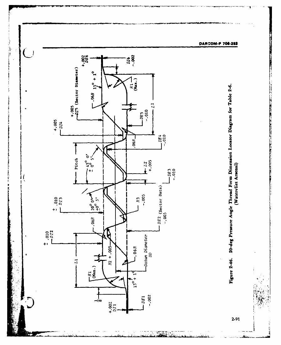
DARCOM-P 70M-293
10 0
! -4
+44
I.I
o2t9
"''.4 ,•
÷,+,,
.'- to .,. ,. ._e.
04 -.I
' , •'• .• I
: i•"'" •• .!: 4..
I I .•m
0.1

S••d• ¶•..¸,¸• l " . ._________....____ -.•p . "••.... - '--- ... . - ". .,.. . a. ;• ; . ---.-. ... ..... .. .. ..... , ...
TASU 29LIST OF SPZCIFICATIONS FOR: CANNON, 155 ama,
HOWITZER, XMI (REF. 91)
No. Tide Number1. Patiinmg For rs Moels A7309995
2. &X4114 (Lr. IAM) A7309997
3. hAvwtw FPi"h (Springs) A7 309993
4. PNw i WA A7309999
S. Mqko Abii S Viual lletio of Thick Walled CAmonTube B8768747
r 6. Mquuec Particl Impetio of Broch Rings aid CGoings(ScMw Type) B8768748
7. Magti Purtide Inmspcim C•ria for Brechlockls (Screw Type) A8768761
8. Mqaetc Airticle Ipetion of Minwr Commn Cwoone B8769067
9. Manetic Aftl Is•pe•on Ceria for Mujwde Devjis A876912310. Towc*p of A*WuW urfaer Finish After BeAching A8769450
11. Geneal Date Co•ering Applictio of Dry Film Lubricant B8769470
12. Simel Ceagt B11577275
13. Generl Datafor 6M, Series Aluminum Alloys A1 1577279
14. Skwe Aueofittiqe Procedures B 11577708
15. Aluminum Alloy Casting Medium trenM B 1157802016. vace Texture ANSI-B46. i17. Interpretation of Drawing Requirm•ents and Geometric
04rackristic Symbols ANS!-Y14,5
18. Stel Sheets, Carbon, Cold-Rolled, CMmercial Qality ASTM-A366
19. Carbon Skdl Sheet, Cold-Rolted, Drawing Quality ASTM-A619
20. Carbon Steel Shoet, Cold-Rolled, Drawing Quality, SpecialKilled ASTM.A620
21. Compound and Sample Prarationfor Physical Testing ofRubber Products ASTM-DI5
22. Tension Testing of Vulcanized Rubber ASTM.D12
23. Law Temperature Impact Test for Fabrics Coated WithFexible Polymric Materials ASTM-D2137
24. lndeuniow Handnss of Rubber and Mastics by Means of aDu ter ASTM-D2240
25. Stl Castings up to 2 in. in Thickness ASTM-E44626. Welding Symbols AWS-A2.0.68
27. Siel, Chemical Composition and Hardenability FED-STD-66
18. Metle. Tist M#tods FED-STD-151
29. Color(Requirements for Individual Chips) FED-STD-595
30. Ffastk Molding Material, Cellulose Acetate Lý-P397 "MS
31. Anodic Coahngs, for Aluminum and Aluminum Alloys MIL-A-8625
(cont'd on next page) C "
2-92
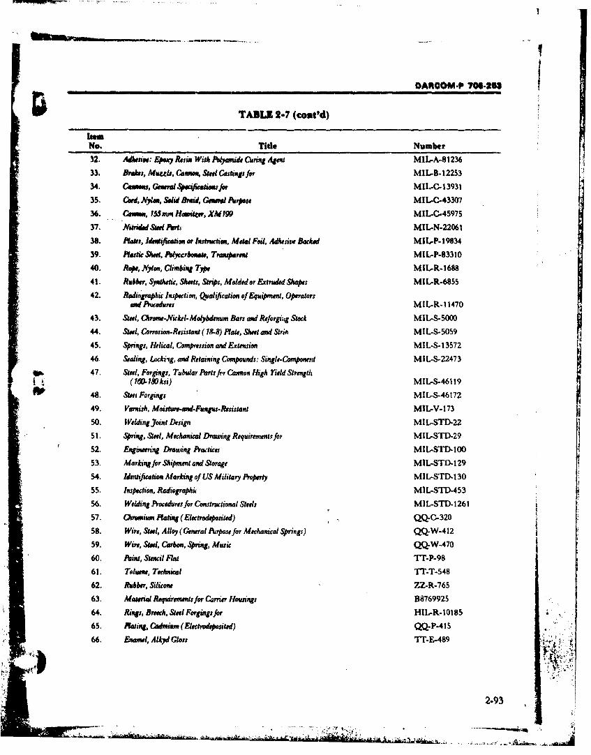
DANCIOM-P 706-M1
TABLE 2-7 (cout'd)
No. Tidle Number32. Adksw: 4..vy Resin With Pyaly de Curing Agent MILA-A8123633. Briskes, Mucdle, Ce...., Stee Castings fer MIL-B-12253
34. COMuuM, GemrelSe 4 catWilaesff MII.-C,1393135. Card. Nylon, Sold Bfid, Gameno Purpose MIL.C-43307
36. Cesiu, 155mna Hamwitcer, XMi 19 MIL-C.4 5975
37. Mitrided Steel Parts- MIL-N-2206138. Plates, IdentificatioR or Inshtiction, Metal Foil, Adhesi~v Backed MIL.P-1 983439. Plartic &Wee, Noycerbonate, Transparent MIL.P-83310
40 Rap, NVYlon, Climbing TOWts MIL-R-1698
41. Rubber, Syjnthetic, Sheets, Strips, Molded or Extruded Shapes MIL.R-6855
42. RedingraWc Inspection, Qualification of Equipment, Operatorsandt Prucedurus MIL.R-1 1470
43. Steel, ChrmrNivckel-Molybdenum Bars and Reforg.,dg Stock MIL-S- 500044. &Stee, Corrosion-Resistant ( 18-8) Ptate, Sheet and Striii MIL-S-5059
45. Sprugs, Helical, Compression and Extension MIL.S-1 357246. Sealing, Lockiifg, and Retaining Com pounds: Single-Compotnent MIL-S-2247347. Steel, Forgings, Tubular Parts fer Cannon High rield Stregth
48. Steet Forgings MIL-S-4617249. Varnish, Moisture-end.Fuingus-Resistant MIL-V- 173
50. Welding joint Design MIL-STD-22
51. Sprng, Steel, Mechenical Drawing Requirements for MIL-STD.2952. Engineering Drawing Practices MIL-STD-10053. Marking for Shipment and Storage MIL-STD-129
54. Identificatio Marking of US Military Property MIIL-STD.I 30
55. Inspection, Radiographit MIL-STD.453
56. Welding Procedures for Constructional Steels MIL-STD-126157. Chromium Raing (Electrodeponited) QQ-C-32058. Wire, Stee, Alloy (General Purpose for Mechanical Springs) QQ-W-412
59. Wire, Steel, Carbon, Stprig, music QQ-W-47060. Paint, Stencil Flat 'If-P-9861. Toluene, Technical ¶fl-T-548
62. Rubber, Silicone ZZ-R-76563. Material Requirementsfor Carrier Housings B8769925
64, Rings, Breeh, Steel Foroginsfor TIIL-R-101 85
65. Plating, Cadmiaun (Electrwdeposited) QQ.P.41 S66. Enamnel, Alky Gloss 'f.-&489
2-93
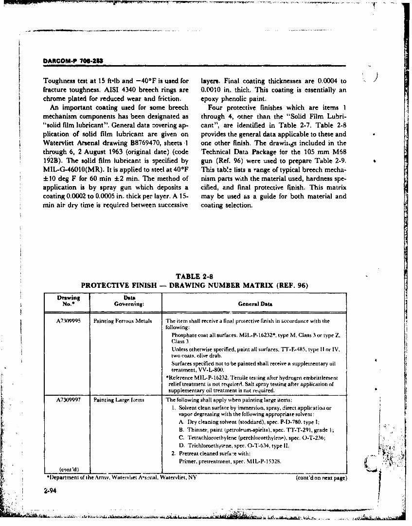
DARCOM-P 70-20
Toughness test at 15 ft-lb and -40OF is used for layers. Final coating thicknesses are 0.0004 to '
fracture toughness. AISI 4340 breech rings are 0.0010 in. thick. This coating is essentially anchrome plated for reduced wear and friction, epoxy phenolic paint.
An important coating used for some breech Four protective finishes which are items 1mechanism components has been designated as through 4, other than the "Solid Film Lubri-"solid film lubricant". General data c-overing ap- cant", are identified in Table 2-7. Table 2-8
plication of solid film lubricant are given on provides the general data applicable to these and
Watervliet Arsenal drawing B8769470, sheets .1 one other finish. The drawithgs included in thethrough 6, 2 August 1963 (original date) (code Technical Data Package for the 105 mm M68192B). The solid film lubricant is 3pecified by gun (Ref. 96) were used to prepare Table 2-9.MIL-G-46010(MR). It is applied to steel at 40OF Th;s tab!! lists a range of typical breech mecha-4-10 deg F for 60 mrin 2 min. The method of nism parts wth the material used, hardness spe-application is by spray gun which deposits a cified, and final protective finish. This matrixcoating 0.0002 to 0.0005 in. thick per layer. A 15- may be used as a guide for both material andmin air dry time is required between successive coating selection.
TABLE 2-8
PROTECTIVE FINISH - DRAWING NUMBER MATRIX (REF. 96)
Drawing DataNo.* Governing: General Data
A7309995 Painting Ferrous Metals The item shall receive a final protective finish in accordance with thefollowing:
Phosphate coat all surfaces. MIL.P-16232*, type M, Class 3 or type Z,Class 3
Unless otherwise specified, paint all surfaces, TT-E-485, type 11 or IV,two coats, olive drab.
Surfaces specified not to be painted shall receive i supplementary oiltreatment, VV-L-800.
*Reference MIL-P- 16232. Tensile tesiing after hydrogen embrittlementrelief treatment is not required, Salt spray testing after application of
_ _ _ _ _ _ _ supplementary oil treatment is not required.A7309997 Painting Large Items The following shall apply when painting large items:
I. Solvent clean surface by immersion, spray, direct application orvapor degreasing with the following appropriate solvent:A. Dry cleaning solvent (stoddard), spec. P-l)-780. type 1;B. Thinner, paint (petroleum-spirits), spec. TT-T-291, grade 1;C. Tetrachloroetbylene (perchloroethylene), spec. O.T-236;
D. Trichloroethytene, spec. O-T-634, type 11..2. Pretreat cleaned surface with: .. . . .
Primer, pretreatment, spec. MIL-P- 15328.
(cont d) ___ _____________________________
*Department of the Army, Watervliet Ars-,nal, Watervliet, NY (cont'd on next page)
+i•+ 2-94___.._ _ _ .
:-+hl+J.'+"* . ,. . . ... . ... .. . . . .. .. ,' , ',•',. • .• +,m, •1 , •:1

DARCOM-P 706,263
TABLE 2-8 (cont'd)
Drawing DataNo. Governing: General Data
3. Apply two (2) coats to pretreated surface with:
Enamel, semigloss, rust-inhibiting, spec. T`T-E.485, type IV, olivedrab no. X24087.
A7309998 Protective Finish The following shall apply:Springs Final protective finish for springs, other than BREECH closing springs.
1. Black oxide coating, class 1, spec. MIL-C-13924.
2. Following the chromic acid dip, springs shall be thoroughlydried and coated with lubricating oil, preservative, general purposespec. VV-L-800.
A7309999 Protective Finish 1. The protective finish shall be type M, class 1, phosphate coatingconforming to specification MIL-P-16232.
2. The supplementary preservative oil shall conform to specificationVV-L-800. The weight per unit area requirement of MIL-P-16232is not required.
3. Following the chromic acid rinse (stage 5) the items shall be
thoroughly dried before application of the preservative oil.
4. Cleaning shall be per TT-C-490 method I and/or II for surfacefinishes of 63 microinch and coarser.
5. Cleaning shall be per TT-C-490 method II for suface finishes finerthan 63 microinch. No abrasive Llast shall be used.
6. Surface finishes finer than 16 microinch shall not require phosphatecoating. If surface finishes finer than 16 microinch are phosphatecoated they shall be maintained or shall be restored to their specifiedfinish
7. Unless otherwise specified, braze shall have a fine line of brazingmaterial visible at the joints after application of the protective finish.
8. Salt spray testing after application of the preservative oil is notS~required.S9. Embrittlement relief (tensile) testing shall not be required unless
specified on the applicable drawing.
10. Articles shall comply with dimensional requirements of the drawingsbefore application of the phosphate coating.
A1 1577717 Aluminum Painting Item shall receive a protective finish as follows:
Base coat (for applicable drawing*)
A. ANODIZE per MIL-A-8625, type i, class I *
B. ANODIZE Pcr MIL-A-3625, type II, class I"
C. ANODIZE per MIL-A-8625, type III, class 1*'
Unless otherwise specified, paint all surfaces as follows:
One (1) coat primer per MIL-P-1 5328
One (1) coat paint per TT-E-485 or olive drab.*When more than one base coat is specified, the contractor has the option
ofwhich one to use.**Seal in boiling deionized water.
The applicable drav, ing shall contain the following minimum informationfor protective finish: ;••::
DWGA 11577717 Base.... ........
2-95

OARCOM-P 70942___
TABLE 2-9
BREECH MECHANISM PART MATRIX (REF. 96)
Material
Carbon RUnge Final ProtectivePart or AISI No. Specification Hardness Finish-Dwg. No.
Body, Breech- AISI E4340 MIL-S-5000 Rc 34/38 A7309999Block
Pivot (3/4 D x 0.28/0 50 C FED-STD-66 Rc 35/41 A73099992-1/2 L)
Plunger 0.28/0.50 C FED-STD-66 R, 34/38 A7309999Lever 0.28/0.50 C FED-STD-66 Rc 35/41 A7309999Bushing 0.28/0.50 C FED-STD-66 Rc 25/31 A7309999
Retractor 0.23 C max FED-STD-66 R A 79/84 A7309999Spring Music wire QQ-W-470 NA* A730998Trigger 0.23 C max FED-STD-66 R, 79/84 A7309999Sear 0.23 C max FED-STD-66 R, 79/84 A7309999Guide 0.38/0.53 C FED-STD-66 Rc 40/46 A7309999
Pivot (5/8 D x 0.38/0.53 C FED-STD-66 Rc 40/46 A7309999
13/32 L)Key 0.28/0.50 C FED-STD-66 Rc 35/40 A7309999Stop 0.38/0.53 C FED-STD-66 Rc 40/46 A7309999Detent 0.28/0.50 C FED-STD-66 R, 30/35 A7309999Retainer 0.28/0.50 C FED-STD-,.i Rc 25/31 A7309999
Bushing 0.38/0.50 C FED-STD-66 R<, 35/41 A7309999Crank AISI 4140 or FED-STD-66 R, 35/41 A730Q999
AIS14340Cover, Disc 0.311 C max FED-STD-66 NA A7309995Body, Breech 0.28/0.50 C A7309999
RingBracket, Breech 0.28/0.50 C FED-STD-66 B, 248/350 A7309999
Ring4
Adjustor 0.28/0.50 C FED-STD-56 R, 25/31 A7309999
Crank 0.38/0.50 C FED-STD-66 Rc 35/40 A7309999Pin 0.28/0.50 C FED-STD-66 Rc 35/41 A7309999Shaft 0.28/0.50 C FED-STD-66 Rc 25/31 A7309999Spring Steel wire QQ-W-412 Rc 50/33 A7309998
Lamp 2 Type II
Lever 0.38/0.53 C FED-STD-66 Re 35.41 A7309999Stop 0.38/0.53 C F'ED-STD-'o: Rc 35/41 A7309999Grip Aluminum Al ;7"/279 NA A11577*/1"
606186 1Cover Strip 0.34 C max FED-STD-66 NA NALatch 38/0.53 C FE.,.19"D-66 R, 34/48 A7309999Extractor 0 23 C max FED-SrD-66 gR 79/84 A7309999
*Not Applicable
REFERENCES
I. TM 9-1900-203, Ar.illery Ammu.aition, April 3. TM 9-1300-200, Ammunition, General, Oc.1%7, Fig. 1-1, p. 1-3 tober 1969, Chapter 4, pp. 4-1, -36.
2. AMCP ;0.-3-3, Engineering Design Hand- 4. AMCP 706-252, Enginzering D-sign Hand- ,ibook, Complete Round Charts- Artillery Ammuni- book, Cun Senes.Gur Tubes, Fig. 2, p. 4.tion, Deceniber 1967. 5. TM 9-1900-203, lArillery Ammunition, April
2-96.
DANCOM-P 70&-2~3
REFEREYCES (cont'dl)
1967, Fig. 1-11, p. 1-19. Handbook, Fire Control Series-Fire Control Sys-6. Maj. Gen. W. K. Ghormley, "The Cornbusti- temns-Genetal, Fig. 1-55, p. 1-70,
ble Case"' Ordnance, September-October 25. TM 9-3007, 105 mmn Hoivit.zer, October 1963,1962, p. 231. Fig. 31, pp. 72-73.
7. IIT Research Institute Private Files 26. TM 9-3305-1, Piinciples of Artillery Weapons,8. US Army Photograph November 1956, Figs. 44-46, p. 41.I9. MII.-HDBK-698, Copper and Copper Alloys. 27. TM 9-3007, 105 mm Hotoitzer, OcLtober 1953,
10. AMC? 706-252, Engineering Design hand- Fig. 32, p. 74.book, Gun Series-Gut: Tubes, Fig. 17, p. 23. 28. TM 9-361, 75 rmm Gun, i-83E1, November
11. ANICP 706-252, Engineering Design 1951, Fig. 18, p. 28.Handbook, Gun Serie!:-Gun Tubes, p. 2.4. 2-9. (G. D'Andrea, Short Recoil Breech Actuating
12. A.MCP 706-2`52, Engineering Des;gn 11and- Mechanism, Watervijet Arsenal, NY, wv'r-book, Gun Series-Gun Tubes,~ Fig. 18, p. 24. 6517, pp. 6-7, July 1965, AD-470 443.
13. AMCP 7106-250, Engineering Design Hand- 30. T. K. Warwick, The Design mad Development ofbook, Gun Series-Guns General, Fig. 6-2, p. 6-5. the Gun, 120 mm, TK., L1 !A2 (U), Roval Ar-
14. AMOP 706..251, F~ngine~ring Design Hand- rnarnent Research and Defense Est'ablish-book, Gun Serifs-Muzzle Devices, p. 7-4. rn.ent, Ft.. Halstead, England, R.A.U)1..E.
15. AMOP 706-251, Engineering Design Hand- Memno-1/64, January 1964, AD-348 023book, Gun Series-Muzzle Devices, Chapter, 7, (CONFIDENTIAL),pp. 7-1, -9. 31. U.S Army Ordnance Dept., A Symposium on
16. AMCPT 706-342, Engineering Design Hand- Breech Mechanisms, Part II, Ord. Project No.book, Carriages and Mounts Series-Recoil 14s- TR-1I OOL, The Franklin Instit~ute, Phila-Urns. de!phia, PA, March 1949, pp. 2-27, -42.
17. A'MCP 706-250, Engineering Design Hand- 32. TM 9-2300-216-10, Oberato-.s Manual fr Gun,book, Guns-General. Field Artillery, Self-Propelled: Fully Tracked, 175
18. AMCP 706-340, Engineering Design Hand- mm, M107 (T235E?) (232YAA36-C-535, andbook, Carriages and Mounts. General. Howitzor, Heavy, Self-Pfrope!14d: Pully Tracked,
19. AMOP 706-327, Engineering Design Hand- 8-Inch, M110 (T236E1) (V350-439-6243), Junebook, Fire Control Series-Fire Control Systems- 1962, Fig. 10, p. 124.General, Fig. 1-s, p. 1-13. 33. US Army Ordnance Dept., A Symposium onl
20. AMOP 70)6-327, 'Engineering Design Hand- Breech Mechanisms, Part II, Ord. Project No,book, Fire Control Senes-Fire C'm)trol S~ystems- TRI-IOOOL, The Frairkn Insi'lotte, PhilA-
2.General, Fig 1-13, pp. 1-19. deiphia, PA, March 1949, pp. 2-2.7-42..2.FM 6-94, 175 mmr Gun Af107 Set'f-Prpelled and 34. US Army Ordnance DcpL., A Symposium ol
8-Inch Howitzer Ml110 &elf.PropelIed, May Breech Mechanisms, Pori III, Ord. Project Noý. po1968, Fig. 10, p. 19~. TRI-IOOOL, The Franklin institute, Phila-
22. FMA 6-94, 175 mm Gun M 107 S'lI.Propelled and riciphir., PA, March 1949, Pg. 2-125.8-inch Hmriit.zer M 110 Self-Propelled, May 35. TM 9-2300-216-10, Operator.; Manual for Gun,1918, Fig. 11, p. 22. Field Artillery, Self-Propelled: Fully Tracktd, 775
'K23. AMCP 70M.331, Engineering Design Hand- mm, M107 (T235E1) (2.350.435-6635) ?ndbook, COmpensating Elements, p. 53. Horietztr, Heavy, Self-Nftrplled: Fully Trocked,
24. AMOP 706-327, Engineering Design 3-inch, M 110 (T236EI) (23A~O439-6243), June .4
2.97
AtCOM.P M064N=GE (ont'd)
1962, Fig. 96, p. 120. tioral Maintenance Manual, Howitzer, Light,36. MIL-C-45525 (WC), Ciannon, 155 mm How- Towed: 105 mm, M 102 ( 1015-086-8104), March
itzer: M126A1, June 1972, p. 2. 1%5, Fig. 30, p. 56.37. T`M 9-2350-217-10, Howitzer, Light, SelfPro- 53. US Army Ordnance Dept., A Symposium on
pdled: 105 tamm, M108 and Howitker, Medium, Breech Mechanisms, Part II, Ord. Project No.Self-propelled: 155 mm, M109. TRI-1000L, The Franklin Institute, Phila-
38. TM 9,4350-217-25P/1, Howitzer, Light, Selj- delphia, PA, March 1949, pp, 2-2.6-1-2-Propellod, 105 mram, M 108 and Howitzer, Medium, 2.7-12.Sslf.Arvpelled: 155 ram, M109, Organization, 54. TM 9-361, 75. mm Gun, T83E1, November
DS, GS and epot Maintenance Manual. 1951, pp. 29-30.39. 'T'M 9-3305-1, Principles of Artillery Weapons, 55. US Army Ordnance Dept., A Symposium on
November 1956, Fig. 49, p. 45. Breech Mechanisms, Part III, Ord. Project No.40. T.J. Hayes, Elements of Ordnance, John Wiley TRI-1000L, The Franldin Institute, Phila-
& &S~, Inc., New York, NY, 1949, p. 239. delphia, PA, March 1949, p. 3-1-5.41. TM 9-3007, 105 mm Houiitrer, MiO1A1, Oc- 56. US Army Ordnance Dept., A Symposium on
tober 1953, pp. 72-73. Breech Mechanisms, Part II, Ord. Project No.42. TM 9-361, 75 mm Gun, T83E1, November TRI-1000L, The Franklin Institute, Phila-
1951, pp. 31-3. delphia, PA, March 1949, pp. 2-2.4-1,.2-2.4-43. 'I'M 9-3305-1, Principles of Artillery Weapons, 3, -26.
November 1956, Fig. 16, p. 46. 57. US Army Ordnance Dept., A Symposium on44. AMCP 706-250, Engineering Design Hand- Breech Mechanisms, Part iIl, Ord. Project No. )
book, Gwis-General, p. 3-9. TRI-1000L, The Franklin Institute, Phila-45. TM 9-350, 155 mm Gun, M2, May 1945, pp. delphia, PA, March 1949, pp. 3-1-26,-73.
38, 61, 62, 100, 122, 124, 131-4. 58. J. T. Hynes, Silicone-Asbestos Obturator Pads for46. TM 9-3305-1, Principler of Artillery Weapons, 175 mm Gun, Ml 13A 1, A Product Improvement,
November 19%6, Figs. 52 and 53, p. 48. Watervliet Arsenal, NY, WVT-7101,47. US Army Ordnance Dept., A Symaposiwn on Fcbruary 1971, AD-726 988.
Breeh Mechanisms, Part II, Ord. Project No. 59. T. 1. Hayes, Elemcnts of Ordnance, John WileyTRI-1000L, The Fra*Iklin Institute, Philq- &. Sons, Inc., New York, NY, 1949, pp. 224-delphia, PA, March 1949, pp. 2-2.5, 2.8-33. 6.
48. TM 9-350, 155 mm Gun, H2, May 1945, p. 60. I'M 9-2300-216-10, Operoeors Masalfor Gun,131. Field Artilky, Slf-Propelled: Fully Tracked, 175
41. TM 9-350, 15i sxm Gun, M2. May 1945, Fig. rmm, M07 (T235EY) (2.,0.436.635) end87, p. k33. Howazte, He&vy, .1'f Propelled: Fully Tracked,
50, •M 9-2306-216-10, Opjwaiors M nuad rJr Gun, 8-Inth, M11O (T236E1) (C750.439.624i), JuneField Artillery, S-el j-Ropellod: Futly Tracked, 175 1962, Fig. 99', p., 123.m ra, AdfY// ' T23ME) (235.436-635) and 61. R. M. Cg',,rkiewicz, "Chieftain Tank", TheHowiLzer, Heavy, Sdj-Projlled: Fully Tra•'ked, Engih-mr, pp. 259-M2, (16 A'.gust 1965).-&Inch, M110(T236E1) (2.U0.,46243). June 62. L.T.J. Mos, enr.d H. D. Warwick, The Dev-
19%2, pp.. 25-7. lonit of Ah# Obturator ft the Gun, 120 mm Tk,51. TM 9-361, 75 mnm Gun, T83EI and 75,mm AA L11A2 (U), Royal Armament Research and
Gult Moe 2.1, Noveaber 1951, Fig, 21, p, Defease Establishment, Ft. Halstead,52. 30. England, R.A.R.D.E. Memo-55/63. 19,5352. TM 9-1015-234-12. Otvrato.' and Orgvzka- (CONFIDENTIAL).
----------. ,-A
DARCOM-P 706.25?
REFERENCES (cont'd)
63. Breech Mechanisms for 'Tank Cannon, Armour 75. AMCP 706-252, Engineering Design Hand-I Research Foundation (now lIT Research In- book, Gun Series-Gun Tubes, pp. 9-12.stitute) Final Report Project K-100, WVT 76. MIL-STD-721B, Definition of EffectivenessArsenal Contract DA-1 1-022.ORD-2182, 20 Terms for Reliability, Maintainability, HumanOctober 1958. Factors, and Safety.
64. TM 9-2300-216-10, Operators Manual for Gun, 77. AR 600-200, Enlisted Personnel ManagementField Artillery, Self-Propelled: Fully Tracked, 175 System.mm, M107 (T235E1) (2350-436-6635) and 78. AR-611-201, Enlisted Career Management FieldsHowitzer, Heavy, Self-Propelled: Fully Tracked, and Military Occupational Specialties.8-Inch, Ml10 (T236E1) (2350.439.6243), June 79. HEL Standard S-2-64A, Human Factors Engi-1962, r , and 72, p. 73. neering Design Standard for Vehicle Fighting Com-
65. US A-ii• Jrdnance Dept., A Symposium on partments, Aberdeen Proving Ground, MD,Breech Mechanisms, Part III, Ord. Project June 1968, Table 5 (p. 42), Fig. 4 (p. 19),
A' *.1-1000L, The Franklin Institute, Phila- Fig. 5 (p. 20), Table 4 (p. 22), AD-691 331.
deiphia, PA, March 1949, pp. 3-1-372,-474. 80. MIL-HDBK-759, Human Factors Engineering66. R. E. Seamands and R. J. Toering. Selecting Design foir Army Material, Dept. of Defense,
Best Recoiling Parts Weight in an Artillery Sys- March 1975, Fig. 47, p. 155.tern, US Army Weapons Command, Rock 81. MIL-STD-882, Requirements for Systems SafetyIsland, IL, April 1971, p. 24, AD-882 471. Program for Systems and Associated Subsystems and
67. R. Rossmiller, Alternate Armament Combina- Equipment, July 1969.Stions for the M551 Vehicle, US Army Weapons 82. AR 70-38, Research Development, Test and Eval-Command, Rock Island, IL, May 1967, AD- uatioz of Materiel for Extreme Climatic Con-814 948. ditions.
68. TM 9-2350-224-10, Operators Manual, Tank, 83. MIL-STD-210, Climatic Extremes for MilitaryCombat, Fully Tracked; 90 mm Gun, M48A3, Equipment.W/E (2350.895-9154),January 1966, Fig. 1 -5, 84. AMCP 706-115, Engineering Design Hand-p. 1-9 . book, Environmental Series, Part One, Basic En-
69. AMCP 706-357, Engineering Design Hand- vironmental Concepts.
book, Automative Bodies and Hulls, p. 2-46. 85. E. C. Theiss, et al., Handbook of Environmental70, N. F. Dickinson, ct al., The Influence of Breech Engineering, McGraw-Hill Book Company,
Orientation on the XM 150 E4 Gun on the Loaders Inc., New York, NY, 1961.Task as Related to the M6OA1E1 Tank, TN 10- 86. Engineers Design Guide, US Army Signal Re-66, Human Engineering Laboratory, Aber- search and Development Laboratory, Ft.deen Proving Ground, MD, 1966. Monmouth, NJ, 1962.
71. FM 6-81, 155 mm Htowitzer, M1. 87. AMCP 706-134, Engineering Design Hand-72. AMCP 706-342, Carriage andk Mounts Series- book, Maintainability Guide for Design.
Recoil Systems. 88. AMCP 706-252, Engineering Design Hand-73. 1. J. Hayes, Elements of Ordnance, John Wiley book, Gun Series-Gun Tubes, p. 64.
& Sons, Inc., New York, NY, 1949, pp. 232, 89. ANSI Y14.5-1973, Dimensioning and Toleranc-240, 24-7, 252, 254, 257, 264, 265. ing, The American Society of Mechanical
74. T. J. Hayes, Elements of Ordnance, John Wiley Engineers, New York, NY.& Sons, Inc., New York, NY, 1949, Fig. 15, 90. Handbook H28 (1969), Screw-Thread Stand-p. 65. ards for Federal &rvices, Parts I and II,
2-99
• . .
rI
DAflOM-P 7M.203
REFERENCES (cont'd)
National Bureau of Standards, March 1970. 94. MIL.S-5000, Steel, C4rome-Nackel, Molybdenum91. MILC-45975, Cannon, 155 mm Howitzer: Bars and Reforging Stock.
M199. 95. MIL-P-16232, Phosphate Coatings, Heavy,92. Fed. Std. No. 66, Steel: Chemical Composition Manganese or Zinc Base (for Fcrrous Metals). J
and Hardeability. 96. Technical Data Package, Cannon, 105 mm93. MIL-R-10185, Rings, Breech, Steel Forgings for. Gun: M68 (MIL-C.45504).
BIBLIOGRAPHY jR. S. Bucher, M107/MI110 Self-Propelled Artilleiy March 1967.
Loader-Rammer Review Program, US Army Technical Memorandum 8-60, Human Factors En-Weapons Command, Rock Island, IL, June gineering Evaluation of the M60 Main Battle Tank,1971, AD-891 656. Human Engineering Laboratory, Aberdeen
I-I. P. Van Cott and R. G. Kinkade, Human Engi- Proving Ground, MD, June i Q.neering Guide to Equipment Design, McGraw-Hill C. L. Woodward and N. F. Dickinson, HumanCompany, New York, NY, 1972. Factors Review of Product Improved Breech Mecha-
MIL-STD-1473-A, Human Engineering Design Cri- nisms, 105.mm Howitzer: M137A 1, Human En-teria for Military Systems, Equipment and Facili- gineering Laboratory, Aberdeen Provingties. Ground, MD, August 1972.
Technical Memorandum 3-57, Physical Force Technical Note 7-67, A Loading Study of the XM 138Problems: 1. Hand Crank Performance for Various Self-Propelled Howitzer, Human Engineering '
Crank Radii and Torque Load Combinations, Laboratory, Aberdeen Proving Ground, MD,Human Engineering Laboratory, Aberdeen December 1967.Proving Ground, MD, March 1957. Technical Note 10-66, The Influence of Breech Ori-
Technical Memorandum 9-60, The Effects of Mis- entation of the XM 150E4 Gun on the Loaders Tasksile length and Weight on Loading Time, Human as Related to the M60A lEl 'Tank, Human Engi-Engineering Laboratory, Aberdeen Proving neering Laboratory, Aberdeen ProvingGround, MD, July 1960. Ground, MD, December 1966.
Technical Memorandum 9-62, A Loading Rate Technical Memorandum 14! -62, A Human FactorsEvaluation of a Pivot Chamber Breech and an Evaluation of the Main Battle Tank, 105 mm Gun,XM102 Howitzer Breech, Human Engineering M6OE1, Human Engineering Laboratory,Laboratory, Aberdeen Provirg Ground, MD, Aberdeen Proving Ground, MD, June 1962.
2-100
--l.,:;., : ... . .- • k ,••,• • •r
"DARCOM-P 706-253
CHAPTER 3
DESIGN CRITERIA ANDPROCEDUIRES - INITIATION
THROUGH PROTOTYPE
3-0 LIST OF SYMBOLS X1 coefficient, in.-' i
A, = breech chamber area, in. Ka, Kis,A. = shear area, in! Kt, coefficients, in.-`
a,, a,, a4 = distances, in. K/n, K", coefficients, in.-'b, = distance from rear face oi block to Kg - bending stress concentration fac-
neutral axis, in. tor dimensionlessb2 distance from front face tL bocU i1o K= tensile stress concentration factor,
neutral axis, in. dimensionlessC tooth clearance, in. k spring constant for closing spring,
SCL C•, lb/deg J ,CQ = distances, in. L1, L4, Le,,A
D1 , D2 f pitch diameters of threaded L,, L& = lengths, in.sectors, in. M = applied bending moment, in..lb
D = rear chamber diameter or equiva- M, = maximum internal bending mo-lent, in. ment, in..lb
d = beam width, in. M2 outward bending moment, in..lbd, = displacement of breech operating M3 = eccentric bending moment, in. .lb
cam from point of initial con, act M. = torque on breech operating crankwith follower, in. shaft. in.*lb
di, 42, ds, Mb = mass of breechblock and compo-d4, dg, dg = distances, in. nents, lb's2/in.
E = modulus of elasticity, psi M, mean of material strength distribu-Ef = free recoil energy, ft.lb tion, psiFs = propellant gas force, lb m. propellant mass, lb'sl/ftF, = total resistance force to recoil, lb mp= projectile mass, lb.s"/ftFt = thread force, lb m, = recoiling mass, lb.sS/ft
FS = factor of safety, dimensionless N = number of rounds fired during ser-g = acceleration due to gravity, ft/ss vice, rounds
h = half thickness, in. n = number of threads engagedhi = height of jaw, in. P1 = horizontal load per jaw, lbhs = height of tie bar, in. P2 = aP, = horizontal load per jaw
=hg minimum distance of thrust sur- perpendicular to P1, lbface from rear face of breech, in. P, = chamber pressure, psi
h4 = height of cross section, in. P. = end thrust, lbhs = spring force lever arm distance, in. Pp = peak chamber pressure, psi
_1, I,, 12, P, = probability of survival, dimension-.,1, = moments of inertia, in. less
3-1-__ L
DAMOM-.P 706-263 ______
p thread pitch, in. c = fixed angle between the horizontalQ = momentum at shot ejection, lb-s and the T-slot in the breechblock,q = modified pressure intensity, psi deg
q= - pressure loading on breechblock, rs/r1 = dimensionless ratio of ex-psi ternal to inner radius
R = radius of breechblock crank, in. 6is = horizontal deflection, in.R& = radius of breechblock operating bvB - vertical deflection, in.
crank, in. 8v - horizontal deflection of reactionR, = radius of breech operating cam, in. loading, centerline remainingRf = fillet radius, in. fixed, in.R, = radius at point I, in. 6v = vertical deflection of block center,R, = cam roller radius, in. in.
r = generalized radius, in. E = strain, in./in.r, = inner radius of breechblock, in. = h/Tr = dimensionless ratio of halfr2 = external radius of breechblock, in. thickness to inner radiusrT = radius defining limits of breech- 0= instantaneous crank angle, deg
block loading function, in. 6A = angular deflection of jaws aboutr4 = T-slot roller radius, in. point A, radS = recoil stroke, ft 0B = angular deflection of breechblock
S1 = direct tensile stress, psi load bearing surfaces, radS2 = outward bending stress compo- OT = total angular rotation of crank, deg
nent, psi 0G = initial angular preload on clesureSt = eccentric bending stress compo- spring, deg
nent, psi 0, = initial crank angle, degSA, SI, SC, = mean time between failures, timeSD, S•, So, units
SH, S, = stresses at subscripted points, psi X = failure rate, failures/ (unit time)sm, = maximum tensile stress in jaw, p; i = mean of distribution of h', in.
Sb = bending stress, psi As = mean stress, psiS, = radial stress, psi IAT = mean strength, psiS, = shear stress, psi = mean of distribution of w, in.S# = tangential stress, psi ;Lz = mean of distribution of Z, in!T = period of operation, time units P = Poisson's ratio, dimensionlesst = period of operation, h p = r/r1 = dimensionless ratio
v= free recoil velocity, ft/s o = normal stress, psiv, = propellant gas velocity, ft/s frj. = standard deviation of h2 distribu-v. = projectile velocity, ft/s tion, in.
W, - recoiling part weights, lb or = S,/q = dimensionless radial stressw = width of cross section, in. as = standard deviation of stress, psix = breechblock displacement, in. 9T = standard deviation of strength, psiy = distance between bore aus and aw, = standard deviation of w distribu-
midheight of breech rings, in. tion, in.Z = section modulus, in! ors standard deviation of Z distribu-
-=a s eat angle, rad tion, in.
2"i ~3-2 ;
,.41,:.i .
DARCOM-P 706-253
(2 = Sel'9 = dimensionless tangential the initial contact position at thestress cam radius starting point to the or-
T..= average shear stress, psi igiri of R, and any position of the- maximum shear stress, psi crank follower to Rc, deg
5 = angle between a line drawn from 4k = elevation angle, degthe center of the crank follower in
SECTION 1. TACTICAL INPUTS TO DESIGN
3-1 REQUIRED OPERATIONAL breech operations. A high required burst orCAPABILITY sustained 0ire rate may dictate use of the sliding-
A statement of the "requirement" or "need" is wedge breech. This breech is more arnmenable to
the logical starting point for an orderly design simple, quick cam-actuated operations. Closingprocess. The military equipmert designer and opening sequences are simplified, thereby
receives inputs to the problem through design red cng cycle time. Complicated automaticF specification or performance goals specified in loading features may be required to reduce the
Sterms of allowable bands prepared by the US load cycle time.
Army Materiel Development and Readiness 33 RATE OF FIRESCommand (DARCOM). These inputs are com-
municated to the design agency or contractor in Specification of the gun rate of fire defines ther deg,-ee of sophistication needed in the breechthe form of a request for proposal (RFP) and arereiterated in the design contract. Quantitative system as well as the need for auxiliary
r nsc omechanisms. Low rates of fire allow manual• • performance bands or specifications are
emphasized in the preparation of these docu- operation of the breech mechanisms while higher
ments. The design specifications have a more rates of fire may require automatic orbasic, tactical origin stemming from documents semiautomatic operation using either an externalgenerated by the Department of the Army (Ref. power source or power tapped -from the normal1). operation of the weapon.
3-4 AMMUNITION REQUIREMENTS
MISSAON AThe specification of the type (or types) of am-MISSION munition required to be fired from a given
*To the br'eech mechanism designer, many of weapon is a major input to the breech designthe design options have aleady been defined process. The size, weight, and type of ammuni-prior to his entry into the design process. The tion and the propellant characteristics andavailability of external power to perform breech energy content are determining factors in theoperational functions is dictated by the type of breech system preliminary proportions (breechweapon system specified (i.e., self-propelled recess dimensions, outside dimension, breech-vez-3us towed). When no external power is block size, etc.). It is important to note that moreavailable, recoil energy usuaily is employed to than one ammunition type may be specified. For
f- perform semiautomated breech functioni. Use of example, the SHERIDAN Weapon System firesrecoil energy necessitates the use of cam-actuated both conventionel rounds and guided missiles.
3-3
- .- , .%•?
DARCOM-P 70"53.
SECTION II. DESIGN PROCESS
3-5 ESTABLISHING FEASIBILITY general configurational characteristics andThe structure of the design process, while corn- material properties before the design analysis can
S posed of orderly elements and carried out in a be initiated. These analyses indicate specificlogical manner, is not exisily described in a timple material requirements and alterations in the con-list of steps. Indeed, the act of designing is a com- figuration requiring changes in the initial layout.plex creative process from design specifications to The process is obviously iterative, requiring closeidea to reality. At an early point in the design cooperation between the designer and analyst.procedure, the iesigner must begin to assimilatethe various inputs (specifications, data, con- 3-7 SUBASSEMBLY LAYOUTS;strair. ts) and synthesize -a feasible concept. To es- COMPONENT DETAILStablish feasibility, the design concept must be As feasibility of a concept is shown and sup-committed to paper in the form of functional port from collaboratng sources continues to be
design layouts, preliminary material selections, port f ho desig source continuesito bebreechpositive, the design sequence can move into abreeh mchaism ntefacs wih te ttal firmer stage. Her'e the subassemblies which willweapon, and mathematical ana!yses of critical firm e. ree th e sos m ul te wc icomponents. These various items are discussed
in pars. !-0 and 3-6 through 3-10. developed, and their components designed orselected.
f 3-6 FUNCTIONAL DESIGN LAYOUTS Subassembly layouts will correspond roughlyto the major mecilanism and elementalDesign feasibility is not fully established until breakdowns of the breech system. Typical (but
a set (or sets) of ftinctional layouts of the breech breakdownsote brssem . T c(:system has bxen produced, incorporating theseveral inputs previously mentioned. These 1. Breech structure and blocklayouts are only the initial drawings, showing the 2. Operating mechanismoverall br.eech system geometry; they include 3. Firing mechanismspace requirements for major breech elements 4. Safety mechanismand working motions of the varikus mechanisms. 5. Obturator.The functional design layouts provide a visual Examrles of subassembly and componentidentification of mnechanism motion and spatial drawings are presented in Figs. 3-1 and 3-2. Theconsiderations to be further developed, examples are Watervliet Arsenal drawings of the
Human factors, producibility, reliability, and firing pin block assembly with details for the 8 in.min'iitainability can be introduced most effec- Howitzer, M2AIE1, and 175 mm Gun, M113.tively into the design at this early phase. Formal The figures illustrate the level of detail requireddesign reviews will be used at a later time to en- as the design progresses. Component drawingssure that such goals are achievable. Much wasted mtust specify concentricity and flatness require-time and effort can be saved if the designer, in ad- inents, dimensional tolerances, materials, anddition to establishing functional feasibility, also protective finishes. Manufacturing capabilitiesconsiders all factors that contribute to a suc- must be carefully considered (see Chapter 4) incessful design. A design checklist prepared using addition to the more subtle impact of surfacethe guidance provided in Chapter 2 may be ap- finish or flatness on mechanical failure modespropriate. (e.g., galling and misalignment). Selection of "• "
The initial layouts provide the basis for obtain- proper breech materials is considered in detail ining analytical support. The analyst requires the paragraphs that follow.
3-4
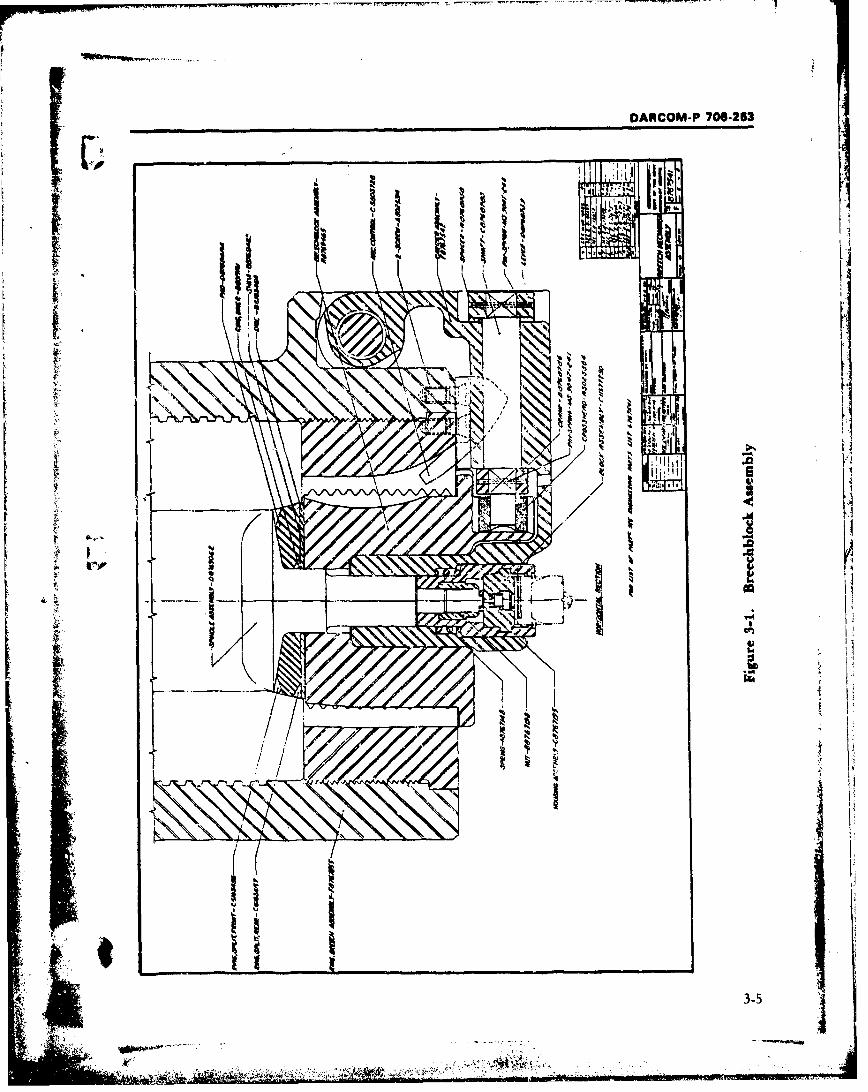
DARCOM-P 706-253
TfT k 1
Ii I
KOO
'00
3-5
4-_"... . .Mona
.
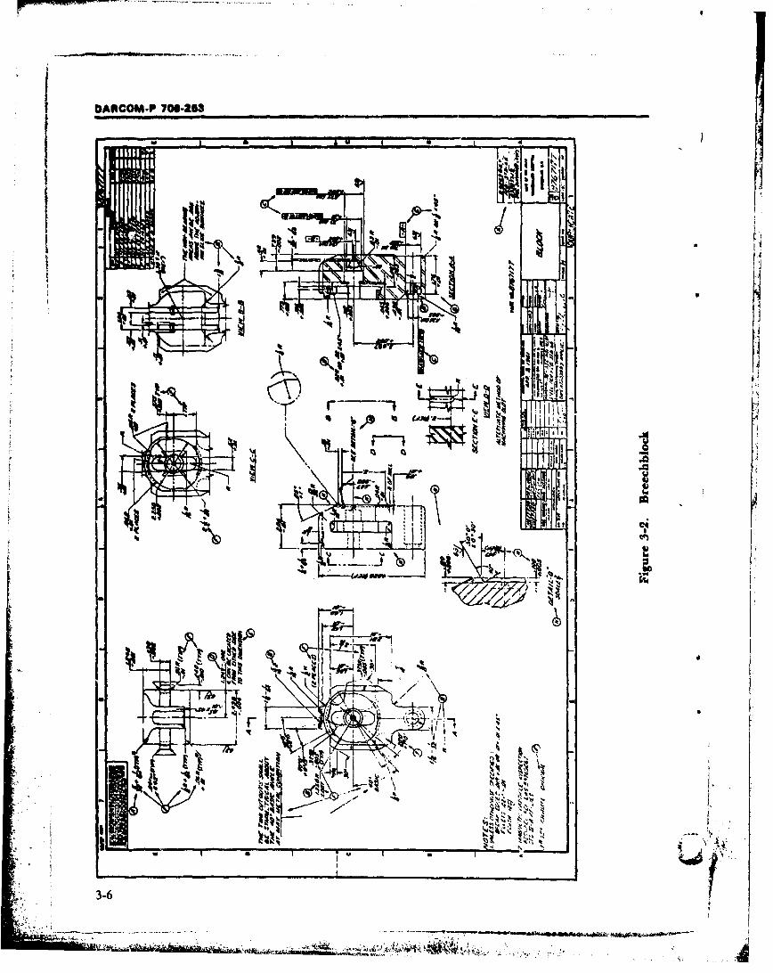
DANCOM.P 700-23
Iwo
-- I-
X eU
I R3Al qý 14i I
V ()L. ''
3-6~
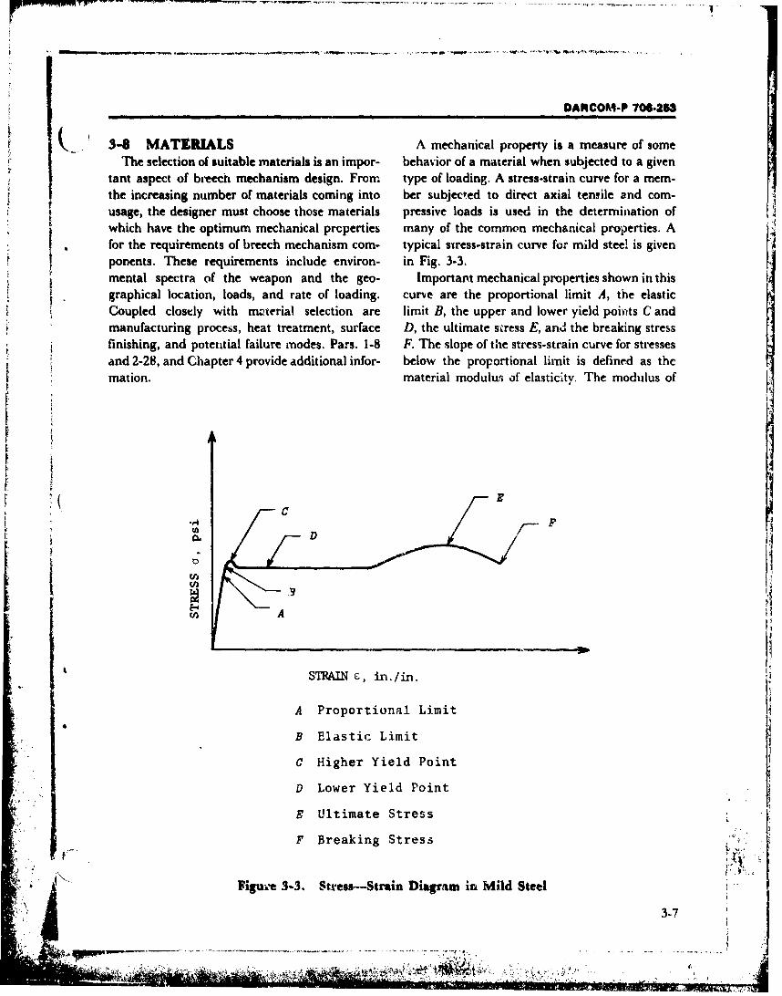
DARCOM-P 706-263
. 34 MATERIALS A mechanical property is a measure of someThe selection of suitable materials is an impor- behavior of a material when subjected to a given
tant aspect of breech mechanism design. From type of loading. A stress-strain curve for a mem-the increasing number of materials coming into ber subjected to direct axial tensile and com-usage, the designer must choose those materials pressive loads is used in the determination ofwhich have the optimum mechanical properties many of the common mechanical properties. Afor the requirements of breech mechanism com- typical swress-strain curve for mild steel is givenponents. These requirements include environ- in Fig. 3-3.mental spectra of the weapon and the geo- Important mechanical properties shown in thisgraphical location, loads, and rate of loading, curve are the proportional limit A, the elasticCoupled clostly with m-terial selection are limit B, the upper and lower yield poiutts C andmanufacturing process, heat treatment, surface D, the ultimate svress E, an d the breaking stressfinishing, and potential failure modes. Pars. 1-8 F. The slope of the stress-strain curve for stressesand 2-28, and Chapter 4 provide additional infor- below the proportional limit is defined as themation. material modulurs of elasticity. The modulus of
IIt
A C PD]
AIIi~~ _________
STRAIN r, in./in.
"A Proportional Limit4
B Elastic Limit
"C Higher Yield Point
D Lower Yield Point
E Ultimate Stress
F Breaking Stress
Figuve 3-3. Stress--Strain Diagram in Mild Steel
3-7
V
DARCt)M-P 706-253
resilience is the amount of energy stored in a uni'h 3-9 BREECH MECHANISMvolume of material which is stressed to the INTEGRATION WITHproportional limit, i.e., the area under the streas- WEAPON SYSTEM
strain diagram up to the proportional limit. The The design sequence cannot pruceed very fartoughness of a material is the energy absorbed by before the several interfaces of the breech3,a unit volume of the material in loading to frac- mechanism with other gun subsystems must beture, i.e,, the area under the Lomplete stress- fully takea into account. Effectiveness of the totalstrain diagrim• Ductiiity is t!,e ability of a weapon and realization of desired requirementsmaterial o withstand large permanent deforma- will not be met--no matter how well any one
Stion without failure. The st-,•in at fract'are is one subsystem is designed (including the breech)-ifgood measure of ductility. tlsign integration between affected interfaces or
Other importnt material mechanical popeur- coPaborating groups is not made. Theties include Poisson's ratio, the ratio of transverse groundwork of presenting the various important
• • to axial strain in uniaxiao. stress; endurance limit,to interfaces between breech mechanisms arid the
the stress causing failure under infinite cyclic rest of the weapon, including the user, isloading; notch sensitivity, sensitivity of a describee in Chapters 1 and 2. Proper integra-material to stress concentrations urder fatigue tion of all subsystems of the weapon requiresSloading; and hardness, the resistance of a systematic liaison with the other engineeringmaterial to scratching, abrasion, cutting, or groups throughout the design sequence.
penetration.A factor that influences material performance
is surface treatment whikh is applied to the mem- 3-40 INTERFACE WITH ANALYSISber to improve one or more of the properties of Mathematical analysis is a tool of great impor-the material. In most cases the process is used tance in breech mechanism design. The designerprimarily to increase such properties as wear and must frequertly use the results of mathematcalcorrosion resistance. The commonly used analysis during the performance of his tasks. Aprocesses are: free interplay between design and analysis dur-
k I. Cold working (shot peening, cold rolling, ing prototype dr-,lopment provides the best, stretching) ground for success. Section III provides examples
2. Surface hardening (carburizing, nitriding, of the analytical techniques commonly used tocyaniding. flame hardening, induction harden- confirm that performance and reliability require-ing) ments will be achieved. Although these analyses
3. Plating (chromium, zinc, cadrnium' often are performed by anahltical groups, the4. Surface finishing (Parkerizing, Parco designer should be familiar with the analyst's
Slubrte, Lubritt). capabilities and limitations.
J
SECTION III. DESIGN ANALYSIS
The importance of mathematical analysis to analysis are conducted during the desig;a piocess. r"the design of breech mechanisms cannot be These include kinematic, kinetic, stress, weight,overemphasized. Tlhe high firing loads and ac- and reliability analyses. The paragraphs thatcelerations imposed on the breech components follow discuss each of these types of analy3is.must be determined to allow sizing of parts and Par. 3-16 presents a brief discassion of the rolematerial selection. Severtl kindb of mathematical u• the digital computer in mathematical analysis.
Ag• 3.87'

DARCOM-P 706-253
The section-conclu6des with illustrative calcula- 3-12 KINETIC ANALYSIStions applied to typical breech component Kinetics is that branch of mechanics which isdesigns., concerned with the action of unbalanced forces
acting on a body and the motion produced bythese forces. Kinetics and kinematics (discussed
"3-11 KINEMATIC ANALYSIS in par. 3-11) form the general area of mechanics
Kinematics is that branch of mechanics which called dynamics. Various proczdures are avail-is concerned with the motion of a body without able for the analysis of bodies subjected to un-consideration of the forces required to produce balancec forcer. All of these procedures havethat motion, Kinematics treats the relationships Newton's laws of motion as their basis. The par-between displacement, velocity, and accelera- ticular procedure most useful for solving a givention. problem depends on the forces acting (constant
Kinematic analysis plays an important role in or variable) and the results to be obtamnedthe design, of breech mechanisms. Definite rela- (displacements, velocities, accelerati'ns, forces,tions must be maintained between the motions of etc.). Kinetic analyses by force, mass, and ac-the various subcomponents of the breech as well celeration; by work and energy; and by impulseas between breech motions and firing and recoil and momentum are ail commonly used in theof the weapon. development of breech mechanisms.
Breechblocks that are operated manually, As in the case of mathematical kinematicusually the interrupted-thread type, generally analysis, kinetic analysis of breech mechanisms sconsist of relatively low speed mechanisms. confined mainly to breeches which are automaticVelocities and accelerations are unimportant in or at least partially automatic irn operation. Thrthe design of these mechanitms. Therefore, the forces and torques necessa.'y t3 activate thekinematic analysis takes the form of determining various components of the breech mnchanism arethe displacements of the various breech compo- found by kinetic analysis so tham they can in turnnents to ensure proper functions and clearances be used to determine the stresses in these compo-between parts. The design layouts (pars. 3-6 and nents. A sample kinetic analysis of the breech3-7) and prototype models (par. 3-19) are suf- operating cx.ank of the 7 r-am, T83 Gun is givenficient for these purposes and no detailed in par. 3-17.2. Work-energy and impulse-mathematical analysis is necessary. momentum procedures are used in par. 3-17.3 to
Automatic or semiautomatic operation of a obtain recoil parameern which are necessary forweapon places stringent requirements on the the breech analysis.kinematics of the breech components. Highvelocities and accelerations are frequently re- 3 13 STRESS ANALYSISquired to meet the specified firing rates. A Stress analysis is the determination of the in-thorough mathematical kinematic analysis is re- ternal force intensities (stresses) in a memnberquired to ensure satisfactory operations of the subjected to mechanical, thermal, and/or inertialbreech mechanism for this case. Par. 3-1 1 con- loading. The tecbriques used in suress anaklysis oftains a typical example of the type of kinematic breech componentb vary from the simpleanalysis required for the determination of the methods of elementry strength of materials (see,motion of the breech operating crank of the 75 for example, Rc.. 2) to highly sophisticated corn-mm, T83 Gun. This gun has a sliding-wedg,- puterized Finite element procedures (see par. 3-
• type of breech as do most automatically operated 16).weapons. The grneral operation of this type of Although hAgh temperatures are involved atbreech is described in par. 2-11. the breech firing chamber interface, thernal 7
3-9 •x
DARCOM-P 708-253
sresses are normally quite Iow in the breech 315 RELIABILITY ANALYSIScomponents and are seldom calculated. Reliability is the probability at a given confi-
Mechanical and irertial loads are high in many dence level that an equipment wili perform a
of the breech compenents and must be deter- specific mission without failure for a specified H
,mined to insure the design will meet all specifica- time period and under cpecified load/stress con-
tions. Sample stress calculations for typical ditions.breech components are given in pars. 3-17.4 Reliability depends to a large extent on proper .through 3-17.8 for open and closed breech rings, manufacturing procedures and quality control
a sliding block, an interrupted-thread block, and tests, but the weapon design engineer makes ma-
the threads of an interrupted-thread block. jor contributions in this field-reliability must bedesigned into the weapon; it cannot be built,analyzed, or tested in. Consequently, it is ex-
,-44 WEIGHT ANALYSIS tremely important that the designer understandOne a3pect of the analytical effort which fre- reliability concepts and methodology so that he
quently is neglected is consideration of weight, can enlist the support of the analyst, the test
material distributions, and material efficiency engineer, and the manufacturer.(Ref. 3). This is unfortunate sirnce weight re- Modern reliability methodology is derived
quirements are extremely important to the con- from the mathematics of probability andceptF of land and air mobility. The analytical statistics and, when effectively applied, demandstechniques of determining part weight and center the close cooperation of all engaged in the design,of gravity location are well known and will not be production, and te:. ing of the item. A detailed
documented here; however, some comments on discussion cannot be presented here; the reader
the importan-c uf weight control as at affects the is referred to such books as Lloyd and Lipow
breech mechanism design are in order. (Ref. 4) and to the DARCOM Handbook series
The breech mechanism, particularly the block, on reliability, particularly handbooks identified
ir a part of the recoiling weight of the weapon. by Ref. 5-8. However, varikus means of achievingFurthermore, the total recoiling weight is estab- reliability are summarized.lished from consideration of firing rate and The more complex a system, the greater the
weapon stability. This means that the breech chance of failure (other things being equal). If
weigh' must be established relatively early in the reliability is exressed as the probability of suc-design process and, once establish-d, is not easily cessful operation, then the reliability of thechanged. Therefore, the breech designer fre- system is equal to the product of the probabilitiesquently is faced with the task of designing a block of successful operation of its parts, provided theywith the restraint of a fixed value of weight, in are statistically independent. Thus, it is possible
addition to the usual restraints of space, strength, to increase the reliability of a breech mechanism
and symmetry. by making it as simple as its performance re-
It is recommended that individual part and quirements permit-by using as few subsystemsassembly weights be computed during the design and components as possible tiat must function to
phase and updated as necessary. 9irmilarly, the carry out the mission of the system as a whole.
center of gravity location should be calculated for Redundancy by overdesigning or providingthe breech assembly as input to the weapon -lternate systerms often provides a direct cowunterdynamics and stability efforts. For more detailed to the product rule of reliability, i.e., the more
information, the reader is referred to DARCOM- alternate subsystems there are, the greater theP 706-193, Engineering Desig." Handbook, probability that one of them, and therefore theComputer Aided Design of Mechanical Systems, Part whole syotem, will operate satisfactorily. Redun- •Two, for weight economy (Ref. 3). dancy of mechanical equipment 3uch as breech
3.10
DARCOM.P 706-203
mechanisms and firing mechanisms is difficult 4. Creep and relaxationand frequently impossible to achieve; however, it 5. Fractureshould not be dismissed without consicieration. 6. FatiguePy carefully designing for mnvxmum strength-to- 7. Wear.weight ratio, the designer often can improve Furthcrmore, the accumulation of failure-rate"safety" or "ovo-rdesign" factors without increas- d.ta for mechanical elements is slow due to theing size and weight, necessarily long time and high cost involved.
Components, subsystems, and materials which Nevertheless, some understanding of the opera-k have demonstrated field reliability should be tional life of equiipment is useful to the mndern
used whenever possible This will increase the gun designer."i probability that these items will be reliable in the Mortality curves attempt to describe the var-
new design. Designs which are "at a limit of cx- ious phases in the life cycle of a product. Fig. 3-perience" !!hould only be used when this is 4VA) shows the cumulative total number of fail-
necessary to achieve a specific requirement. New ures plotted against the life of the product; thesystems or components should be subjected to zero on the abscissa refers to the product being
accelciated life and environmental tests when- ccmpleted. Shortly after that, as various perfor-ever possible ac part of the design development mance and acceptance tests are run, failures oc.and reliability demonstration. cur at a rapid rate. These failure,, known as the
SReliability is further increased in the detail "infant mortality" phase in the life of the part,
design phases by specifying the proper raaterials are caused by workmanship errors, major designand protectivw finishes, by designing against the errors, etc. As these initial defects are remedied,extreme environments encountered (particularly failures drop off to a lower rate which representscl'madc extrzmes, shock, and vibration), and by the normal operating conditions. In this phaseproviding the bes' and most practical types of (constant-hazard-failures), failures occur mainlylubrication for field conditior.s. as a result of some other part within the system.
These failures are truly random. This lower rate
3-1511 MECHANICAL SYSTEM of failure occurrence continues for a relativelyLIMITATIONS long time throughout the useful life of the
product. Finally, the end of the normal life spanIn spite of the rapid growth and wide usage of is reached and the parts begin to wear out, rais-
reliability analysis, the techniques presently ing the rate of failure accumulation.aivailable have severe limitations in their applica- In Fig. 3-4(B), instead of plotting accumulatedtion to mechanical systems. It is generally con- failures, the mean time between failures (MTBF)ceded that the state of the art of reliability predic- is shown. The MTBF is relatively low in earlytion for nonelectronic compornents is not nearly life, higher during the normal life span of the pro-as far advanced as the techniques used for elec- duct and again lower during the wear-out phase.tronic components and systems. To the extent In Fig. 3-4(C) "failure rate" is plotted "xgaintstthat reliabiiity pmedictions in (he electronics field time.are based upon data obtained from large-scale In view of the fact that the region c-f constantreliability te,,ts, there is, with few exceptions, no hazard failures (useful life) has demanded majorpzrallel to be found in the case of mechanical e.e- attention in the study of reliability attemptsments. The reason is sitaply the -.omplexity of were made to formulate it numerically. For thismehanical lailure phenomena sucL as: purpose reliability was stated quantitatively as ,x' •
S 1. Excessive e.kastic deflection the probability that a part of a system will per.2. Elastic buckling form a specified function, under specified condi-3. Plastic deformation tions, for a specified time. This probability may
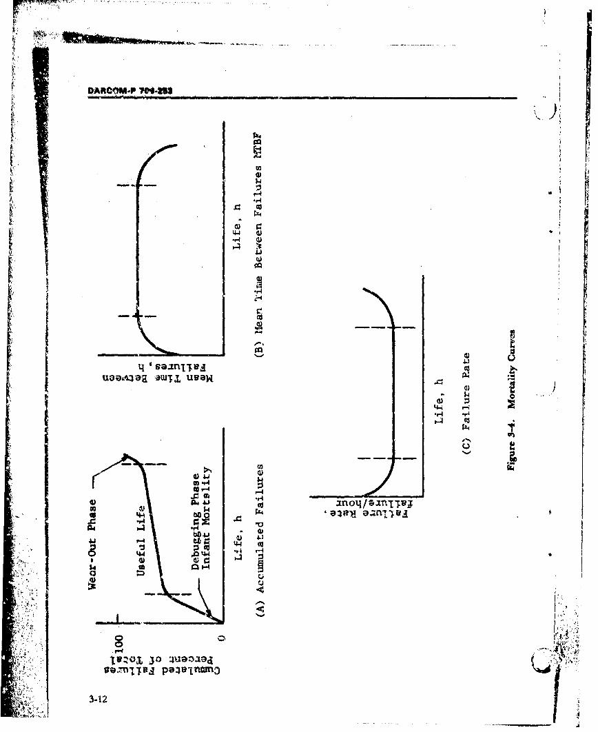
DARCOM-P 704-MS
'A'.0 c
r4
ww4 'S8flflW -go
'4-' w-q
$4 1
r caU 4-4 0;o 4-4~ 'flj
14-
$44
r~~ 3-12f
DARCOM-P 706-263
be assumed to b.-, an exponential function relat- 5. Develop reliability formula.ing the constant failure rate ox the system to time 6. Compile parts lists.for which the reliability is to be estimated. This 7. Perform stress analyses."exponential failure law" gives the probability of 8. Absign failure rates or probabilities of sur-survival P, as vival.
P. = exp(-XT) (3-1) 9. Combine part failure rates (or probabili-ties of survival.)
where is the failure rate (number of failures perlock failure rates orunit of time) and T is the period of operation ib1 10.abodipes
which the probability of survival is being sehvs-d. rlaiiis11. Compute system reliability.Since failure rate is the reciprocal of MTBF, thereliability can Also be stated as 3-15.3 PROBABILISTIC DESIGN
•:P•=exp - T/# (3-2)Probabilistic design is one of the more recent
where Y is the MTBF expressed in the same time developments of reliability methodology. It isunits as T (usually hours). particularly applicable to mechanical reliability
Thus, if the failure rate of a part or a system is problems in the form of a stress/strength inter-known, one can predict its reliability. This, of ference theory. Unfortunately the theory resultscourse, is based on the assumption that the ex- in procedures that are, in most cases, difficult toponential failure law holds. The reliability nono- conddct, time-consuming, and expensive. In ad-graph (Fig. 3-5) allows a rapid solution to Eqs. 3 dition, the lack of adequate information on the
L 1 and 3-2. A sample reliability analysis based on variance of mechanical properties frequently ren-constant failure rate is given in par. 3-17.9. ders the technique useless.
A complete discussion of the stress/strength
"TANDARDUPES ICTIinterference theory is beyond the scope of thisdesign handbook, and the reader is referred to
The real value of anw numerical expression lies Refs. 9-16. However, the basic ideas involved arein the information it conveys and the use made of of interest to the breech mechanism designer andthat information. Reliability predictions do not, particularly useful in the assignment of safetyin themselves, contribute significandy to the re- factors.liability of a system. Rather-, they constitute cri- The basic idea behind reliability is that a giventeria for selectilig courses of action that affect part has certain physical strength propertiesreliability. Persons making reliability predictions which, if exceeded, will result in failure. Further,should be aware of the role of prediction in ir- this property, as all properties of nonhomo-proving and assuring reliability. geneous materials, varies from specimen to speci-
The techniques of making reliability predic- men. Thus, for a particular part or material antions on mechanical equipment such as breech estimate of the mean value and of dispersion ofmechanisms are many and complex. Therefore, the strength property may be found by testing.the designer is referred to various books on the The operating stress imposed on a part variessubject (Refs. 5-8, and 9-20). A very general step- as well as the strength. These stresses vary fromby-step procedure is presented. time to time in a particular part, from part to
1. Define the system. part in a particular design, and from environ- -
2. Define failure. ment to environment. An estimate of the mean v.3. Define operating and maintenance condi- value and of the dispersion value of the operating
"tions. stress must be determined by test, analysis, or ex-4. Construct reliability block diagram(s). periment.
3-13
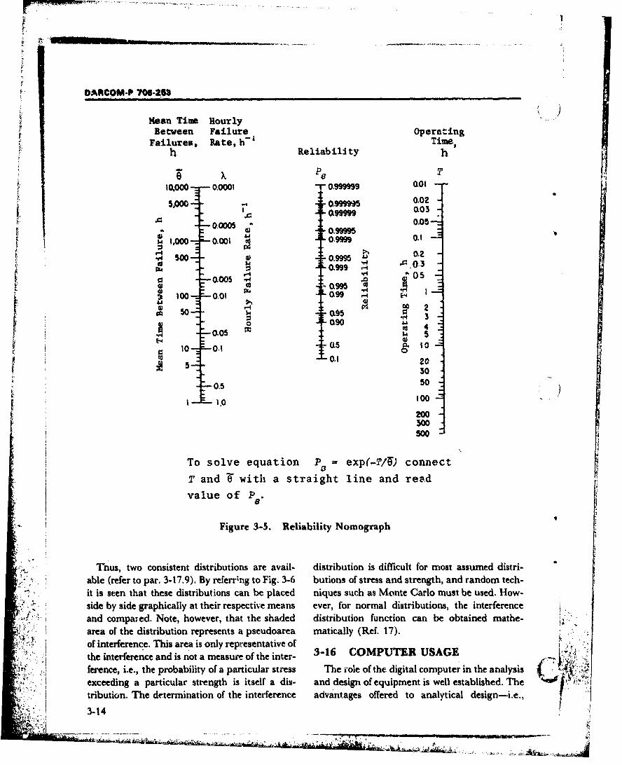
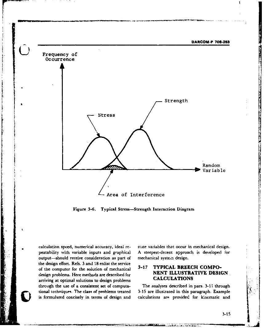
DARCOM-P 706-253
Frequency ofOccurrence
Strength
Stress
Random
Variable
Area of Interference
Figure 3-6. Typical Stress-Strength Interaction Diagram
calculation speed, numerical accuracy, ideal re- state variables that occur in mechanical design.peatability with variable inputs and graphical A steepest-decent approach is developed foroutput-should receive consideration as part of mechanical systein design.the design effort. Refs. 3 and 18 enlist the serviceof the computer for the solution of mechanical 3-17 TYPICAL BREECH COMPO-design problems. Here methods are described for NENT ILLUSTRATIVE DESIGNarriving at optimal solutions to design problems CALCULATIONSthrough the use of a consistent set of computa- The analyses described in pars. 3-1I through
Stional techniques. The class of problems treated 3-15 are illustrated in this paragraph. Exampleis formulated concisely in terms of design and calculations arm provided for kinematic and
3-15
DARCOM-P 706• 63
kinetic analyses of a breech operating crank -. )(pars. 3-17.1 and 3-17.2), dynamic analysis ofbreech recoil parameters (par. 3-17.3), stressanalysis of open and closed breech rings (pars. 3-17.4 and 3-17.5), stress analysis of sliding block(par. 3-17.6), stress analysis of an interrupted-thread block (par. 3-17.7), stress analysis of blockthread (par. 3-17.8), and constant failure ratereliability analysis (par. 3-17.9).
3-17.1 KINEMATIC ANALYSIS OF
BREECH OPERATING CRANK
An example of kinematic analysis is the deter-mination of the motion of the breech operatingcrank in the 75 mm. T83 Gun. Motions only dur-ing the counterrecoil of the gun will be con-sidered. A description of the action of the mech-anism follows.
During counterrecoil (Fig. 3-7), the gun movesforwaid and the cam follower on the breechoperating crank strikes the breech operatinguncam, which is fixed to the gun cradlee As the gunmovcs toward the battery position, the operatingcam forces the operating crank to rotatedownward.
Fig. 3-8 schematically shows the breech oper-ating crank in three p.•sitions during the coun-terrecoil:
1. Follower at the point of initial contact withthe cam.
2. Follower at the point where the camchanges from a straight to a curved profile.
3. Follower at an arbitrary point on the
curved portion of the cam.
Due to the discontinuity in the curvature of thecam, i.e., a straight line section and a curved sec-tion of constant radius, two equations are re-quired to express the rotation of the operatingcrank with respect to time during counterrecoil.These are Eqs. 3-6 and 3-11.
From Fig. 3-8 (and where symbols are de-fined) when the follower is between positions 1and 2, o j
d = RbsinOl + Racos(OT - 0), in. (3-3)
3-16
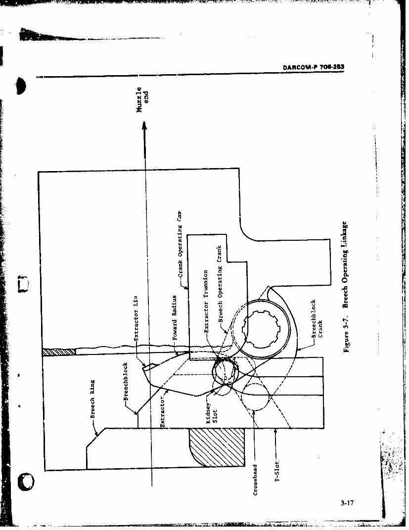
_ _ _ _ _ _ _ _ _ _
DARCOM-P 706-253
fr4
12OECua
e-
144
0)0
w J
CC.3-1
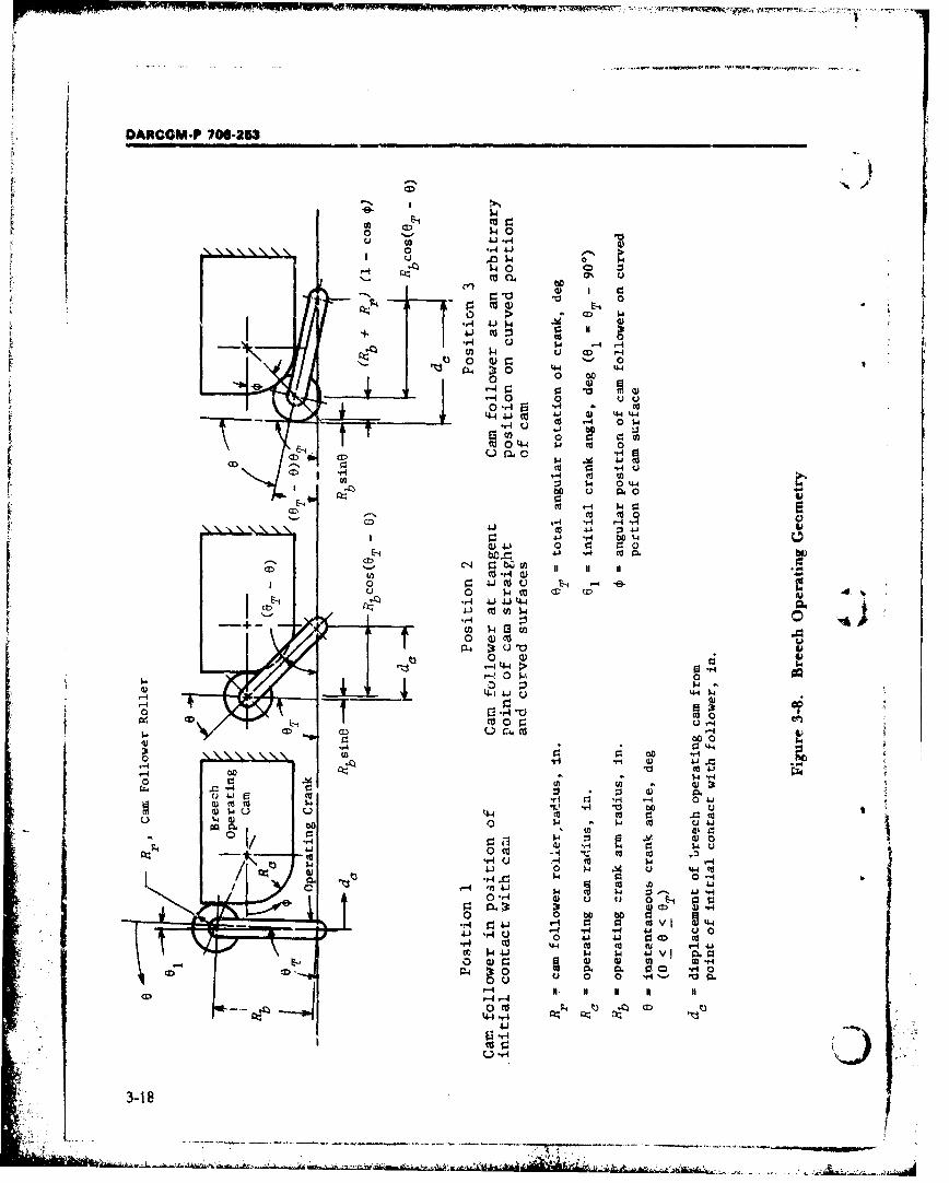
DARCCM.P 706-253
CD
(31~w00
0% C.
0 ý4 1-
-9-~24 0 34.4 4.40 (30
I 0rI 14 tid44 4J 4J 4.4 44
A. 00 J
Ca r 0 w4041 -.p Cdj 02
CD $ 04.4
co :1 $4 0 44
to
.-4 44 14-
41 0 C-3 04
4.) ..4 9:
4JO C), 0- 6; -t-(D 11 1
0 0 )4J 3dU E
-u- 0 ý4L-,4 4- J -
U) *4 434
0~~ 1Cor'0~~ C 0) ,
0~- >~'4a
Co~c 00 .,
4J4
-4 0 4
b0 00 p00u4Ca ~ 4 0 V 03.4.' .' 0 00 0 'j -4 u
o) 0)0 g: 0)W .u .0 0 o E
0 01 *.-'- 0 C g.
0 N II N N I
r4-4 1-4
"-r4
3-18
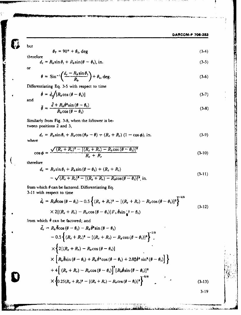
DARCOM-P 706-253
& butthreor OT 900 + 01, deg (3-4)
de Rbsin~l + Rbsin(0 - 01), in.(35or
0 =Sin-('- Rbsn) + 01 deg. (3-6)
Differentiating Eq. 3-5 with respect to time
6=de/[Rb Cos (0 - O)1()a n d + b s n ( - 0 1J+b'if(-l (3-8)
R& cos(0 -0ý)
Similarly from Fig. 3-8, when the foliower is be-tween positions 2 and 3,
d,= R&sin C + Rtcos (OT -0) 1~- (Re + Br) (I -COSi) in. (3-9) *where
IOO (Re, + Rr.)2 - [(Re + R,) - RbiCOS (0 -01)?~ (3-10)Re +Rr
U, therefore
from which 0 can be factored. Differentiating Eq.3-11 with respect to time
RA~OS (0 - 1 ) -0. 5{(Re + r) [R R) COS ( 0)]- b ~ 1 ) J I( 3 -1 2 )
X( 2 [ (Re + Rr.) - Rb COS (0 - 0,) 1' P) hin -01)
!rom which 0can be factored; and
Ra,#cos (0 - 01) - Rb 6' sin (0 - 01)
- 0.5 { (Re + BR,) 2 - [(Re + R,) - RbCO-3 (06 iI}
X{12[(RC + Br) - RbCOS (d0 01]
X Rbisin (0 - 01) + Rb 2OcS (0 -01) + Rj&'Psin' (0 - 01 )]
-+ 4(Re + BR) - Racos (0 - 01)]" [Rb6sin (8 - 001)2
IDX {0. 25 (R + BR,)s -(R, R,) -b Rcos (0 - 01)i} (3-13)
3-19
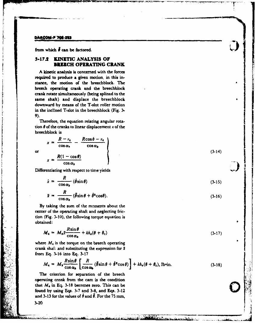
from which I can be factored.
3-17.2 KINETIC ANALYSIS OFBIRECH OPERATING CRANK
A kinetic analysis is concerned with the forcesrequired to produce a given motion, in this in-stance, the motion of the breechblock. Thebreech operating crank and the breechblockcrank rotate simultaneously (being splined to thesame shaft) and displace the breechblockdownward by means of the T-slot roller motionin the inclined T-slot in the breechblock (Fig. 3,-9).
Therefore, the equation relating angular rota-tion 0 of the cranks to linear displacement x of thebreechblock is
R - r4 Rcos6 - r4XcoS ot COS of
or (3-14)R(I - Cos06)Xm
Cos ab ,-
Differentiating with respect to tinre yields
Ri =- (Osin0) (3-15)
COS ofb
RS- (#sinG + 61 cosO). (3-16)COS ab
By taking the sum of the moments about thecenter of the operating shaft and neglecting fric-tion (Fig. 3-10), the following torque equation isobtained:
RsinOM4 = MaRi + kh,(O +O) (3-17)
cos a,
where M, is the torque on the breech operatingcrank shaft and substituting the expression for 2from Eq. .3-16 into Eq. 3-17
Rsino [ RRi M-b (UsinO + Scoso)] + kh,(O + O0), lbein. (3-18)Mcow, ccsci
The criterion for separation of the breechoperating crank from the cam is the conditionthat M# in Eq. 3-18 becomes zero. This can be 41found by using Eqs. 3-7 and 3-8, and Eqs. 3.12
and 3-13 for the values of • and U. For the 75 mm,
3-20
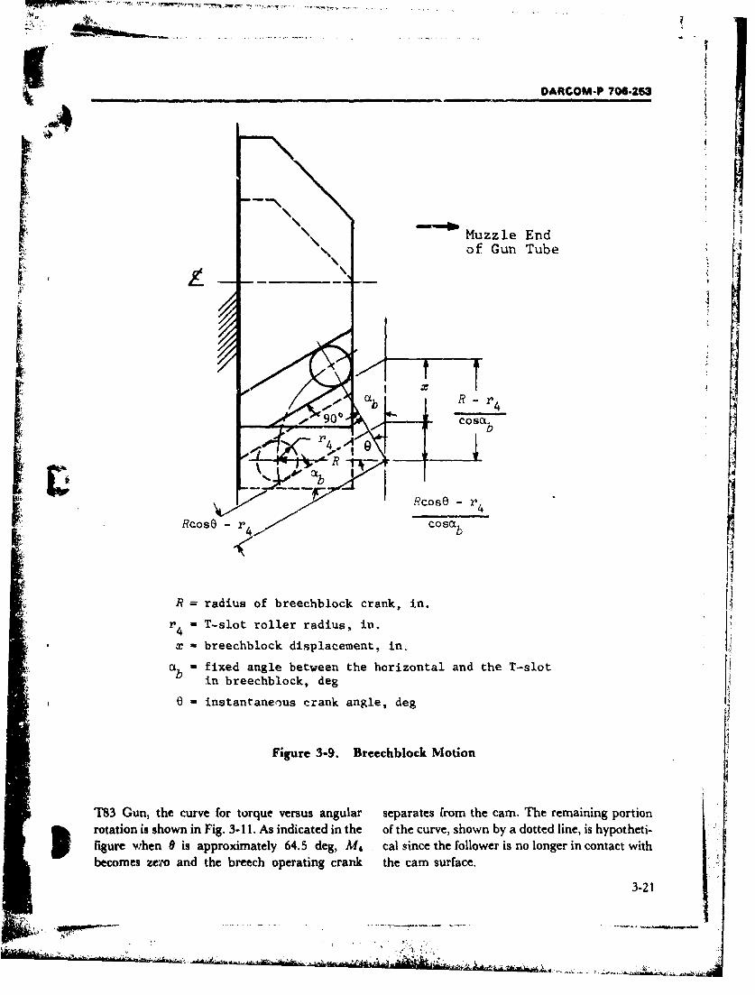
-, DARCOM-P 706-263
Muzzle Endof Gun Tube
r 4asb
IC RcosO - r4
RcosO - cosab
R = radius of breechblock crank, in.
r 4 - T-slot roller radius, in.
x - breechblock displacement, in,
ab - fixed angle between the horizontal and the T-slotin breechblock, deg
6 - instantaneous crank angle, deg
Figure 3-9. Breechblock Motion
T83 Gun, the curve for torque versus angular separates from the cam. The remaining portionrotation is shown in Fig. 3-11. As indicated in the of the curve, shown by a dotted line, is hypotheti-figure when 9 is approximately 64.5 deg, M4 cal since the follower is no longer in contact withbecomes zero and the breech operating crank the cam surface.
3-21
--, " .• .'
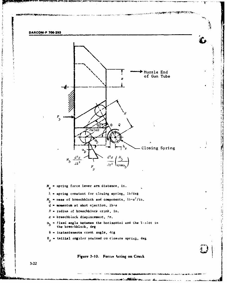
DARCOM-P 706-253
T ininMuzzle Endof Gun Tube
S....k- .... Cosing Spring VMb d____~x M !:
XI
F COB2
I:sine
M s pring force lever arm distance, in.:!,
Bh
,k spring constant for closing spring, ib/deg
SM. - ases of breechblock and components, lb.sa2 /in.
Db
Q omentum at shot ejection. lb.s
R-radius '.f breechblocjr cralnL, in. " !
=. breechbiock dispdacemedt, 2n. '2
-~ fixed angle between the horizontal cnd Lhe 1-51.ot in !Ithe breeehblock, dg 2
M - instantaneous crank angle, in.
k - initgal contantlr preclin osure sprli, deg
C
F. - fgure 3-10. Forces ncian dt on 0r1]k I3.22
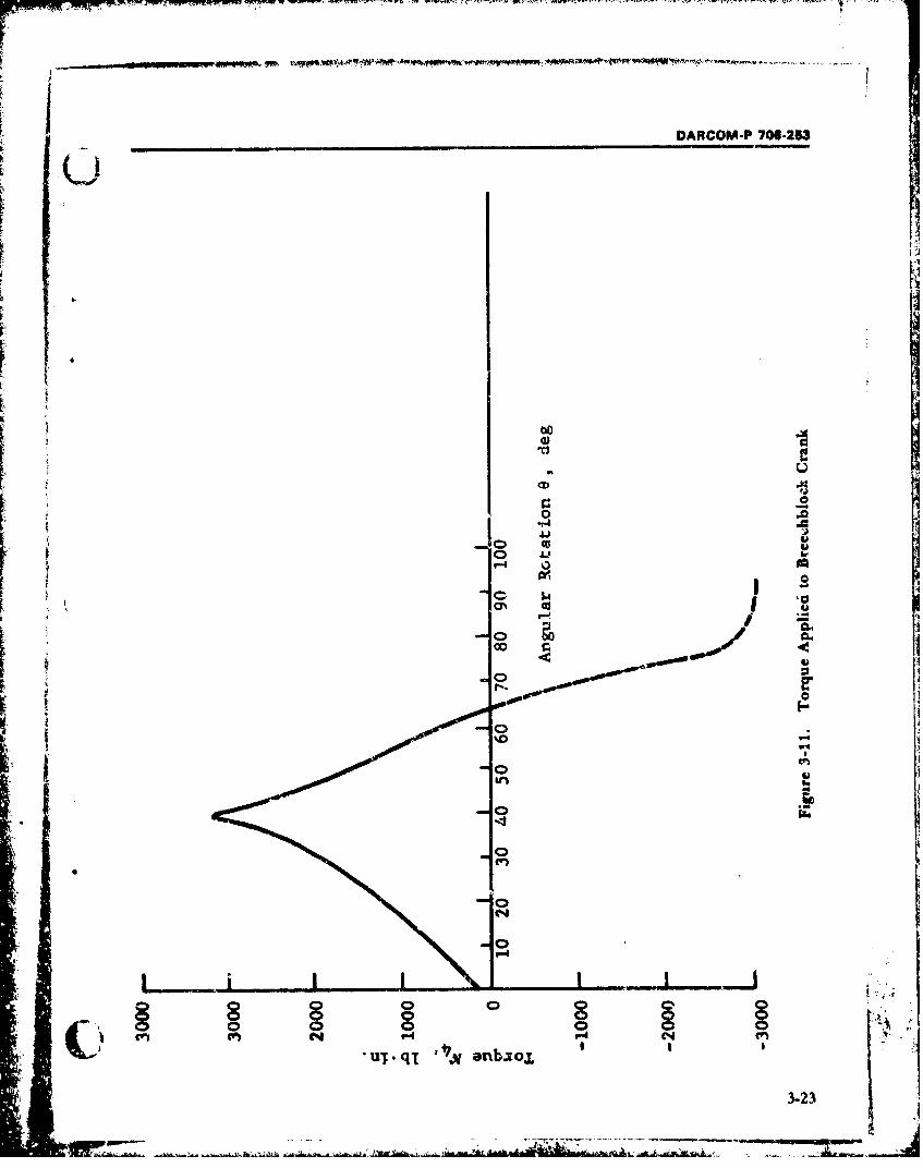
DARCOM-P70-5
~-c4
4-4
00 rw
V1~
4r
A L - - -- -ý
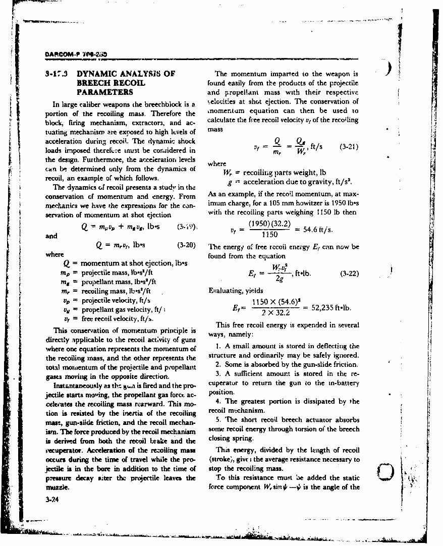
-tL
t DARCOM-P Jft'4
3-17.3 DYNAMIC ANALYSIS OF The momentum imparted to the weapon isBREECH RECOIL found easily from the products of the projectilePARAMETERS and propellant mass with their respective
In large caliber weapons the breechblck is a Ltelocitles at shot ejection. The conservation of
portion of the recoiling mass. Therefore the nomenttim equation can then be used toblock, firing mechanism, extractors, and ac- calculate the free recoil velocity vf of the recoiling
tuating mechanism are exposed to high ltvels of massacceleration during recoil. The dynamic shock Q tloads imposed thcreftk'e mu3t be considered in Mr W,
the design. Furthermore, the acceleration levels wherec~xn bt determined only from the dynamics of
recoil, an example of which follows. g =acceleration due to gravity, ft/sI.The dynamics oG recoil presents a study in tha
conservation of momentum and energy. From As an example, if the reco-.l momentum, at max-
mechanics we have the expressions for the con- imum charge, for a 105 mm howitzer is 1950 lbes
servation of momentum at shot ejection with the recoiling parts weighing 1150 lb then
aM~,,vp + msvs, lb-s (1950)(32.2)mQ v + ~s bs (•••,Vf 54.6 ftis.S and 1150
Q = mrv10, lbes (3-20) The energy of free recoil energy E, can now bewhere found from the equation
Q = momentum at shot ejection, lb.s WV(3mp= projectile mass, lb.s2/ft E= ft-lb. (3-22)m. = propellant mass, lb.s'/ft 2g
Mr = recoiling mass, lb-s'/ft Evaluating, yieldsvp = projectile velocity, ft/s 1150 X (54.6)2vg = propellant gas velocity, ft/i Er= 2 X 32.2 52,235 ft-lb.vt =f free recoil velocity, ftis. This free recoil energy is expended in several
This conservation of momentum principle isdirectly applicable to the recoil act;vity of gunswhere one equation represents the momentum of 1. A small amount is stored in deflecting the
the recoiling mass, and the other represents the structure and ordinarily may be safely ignored.total mornientum of the projectile and propellant 2. Some is absorbed by the gun-slide friction. Lgases moving in the opposite direction. 3. A sufficient amount is stored in the re-
Instantaneously as th- ..gua is fired and the pro- cuperator to return the gun io the mn-battery
jectile starts moving, the propellant gas forct ac- position.celeiates the recoiling mass rearward. This mo- 4. The greatest portion is dissipated by thetion is resisted by the inertia of the recoiling recoil mch-nism.Smass, gun-slide friction, and the recoil mechan- 5. The short recoil breech actuator absorbs
Wsn. The force produced by the recoil mechanism some recoil energy through torsion o" the breechis derive.d from both the recoil brake and the closing spring.
kecuperator. Acceleration of the re.-oiling mass This energy, divided by the lIngth of recoilocurs during the time of travel while the pro- (stroke), givc ithe average resistance necessary tojectile is in the bore in addition to the time of stop the recoiling mass.presure decay cter the projectile leaves the To this resistance mumt 3e added the static 0muzzle. force component W, sin •# is the angle of the
3-24
V.:.• -. . . . .•. . .•,.• • • ••~ ••.. , .,,,, , . . .... ... .•.. '"i .... • / '
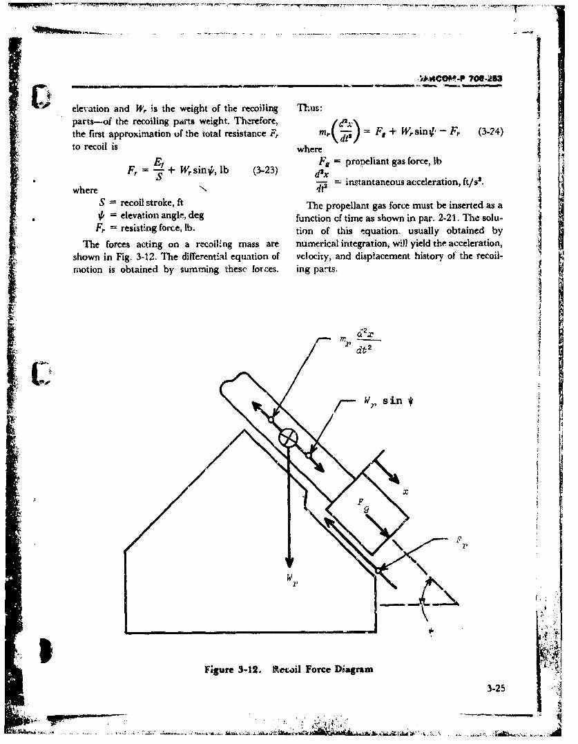
elevation and W, is the weight of the recoiling Thus:
parts--of the recoiling parts weight. Therefore, d. +Fthe first approximation of the total resistance F, mr Fg + Wrsin Fr (3-24))S
to recoil is where G
Fg = propellant gas force, lb_ .F= " + Wr sin#,,lb (3-23) = instantaneous acceleration, ft/s'.
where N 4t2
S = recoil stroke, ft The propellant gas force must be inserted as a= elevation angle, deg function cf time as shown in par. 2-21. The solu-
Fr = resisting force, lb. tion of this equation, usually obtained by
The forces acting on a recoiling mass are numerical integration, will yield the acceleration,shown in Fig. 312. The differential equation of velocity, and displacement history of the recoil-motion is obtained by summing these forces. ing parts.
IrI- -j
d t 2
F'F
rr
;4
-Ak
Figure 3-12. Rtecoil Force Diagram
3-25
4<.
~ OARCOM.P 706-253
V 3-17.4 STRESS ANALYSIS OF OPEN where -- '
BREECH RING P, = load perjaw, lb
Many large artillery weapons employ a P= chamber pressure, psisliding-wedge type breechblock for use with car. breech chamber area, in.tridge case ammunition. The breechblock is nor- The dimensions associated with Fig. 3-14 aremally rectangular in section ard slides across the definedbreech end of the gun within grocves in the maximumjaw thickness, in.oreech ring. The grooves are at near right angles d2 = minimum jaw thickness, in.to the axis (,f the gun and are arranged so that the L, = moment arm for P1, in.breechblock, as it slides into firing position, is L2 = moment arm for P2, in.wedged against the base of the cartridge case. h, = jaw height, in.
The breech ring is usually of rectangular sec- hg = minimum distance of thrust surfacetion, with two slotted jaws between which the from rear face of breech, in.breechblock slides. For the smaller guns, these y distance between bore axis and mid-are separated, as shown in Fig. 2- 13(A), and the height of breech rings, in.ring is called an "open breech ring". 2,R = total load, lb
A complete analysis of the stresses acting on a a, = P, moment arm for section dr, in.breech ring should include not oniv the static and a2 -PA moment arm for section d2, in.dynamic external loads, but also any internal,% = horizontal load (where p2= aP1 forresidual stresses resulting froma ,orming and small a) when the seat angle a is pres-machining processes, as well as Inertial loads ent, lbresultant from the ring kinema:ics. It should be a = sear angle, radnoted also that one or more modes of fiailure are by = horizontal deflection of block center,possible-such as static yieldin~g, fatigue failure, in.surface spaing or pitting, or impact fracture.6v = vertical deftection of reaction loading,
A simple and usually adequate approach to centerline remaining fixed, in.the analysis involves the calculation of nominal = angular deflection ofjaws aboutstresses which are then modified by applying point A, rad.cor,-ection factors obtained from laboratory
The load applied to each jaw is thus P1, and themodels. Also of interest are the deflection and
rotation of the jaws during the firing period. direct tensile stress S, in the smallest section ofeach jaw, is
When a gun is fired, pressure from the gases isexerted on the breechblock and transmitted to S, P= / d(hd), psi. (3-26)the breech ring. For the purpose of this stress The bending moment M. tending to push each
analysis, it is assumed that the load is evenly dis- jaw outward istributed between the jaws (Fig. 3-14) and dis- M2 = A'la,, lb-in. (3-27)tributed uniformly along a line through the cen-ter of the bearing surface. Also, the centerline of which reslts in an otward bending stress cor-the jaws does not usually coincide with the cen- ponent S. of
terline of load application, as illustrated by the 4'f 2d, (3-28)eccentricity y in Fig. 3-14. 21a
Tn.. total load 2P, applied to the breechblock where the moment of inertia I1 isand transmitted to the breech ring is hid ,
-2i P 4 lb (3-25) 2 12 in (3-29)'
3-26
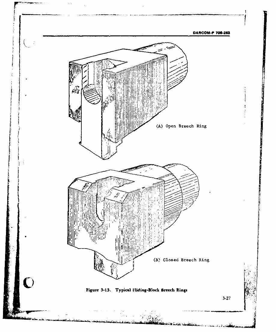
OARCOM-P 706-253
100. ' 100Ii1j'1
~ ~ (A) Open Breech Ring
~ j'
-- ,I (B), Closed Breech Ring
Figure 3-13. Typical Ek~ing-Bloch Breech Rings
3-27
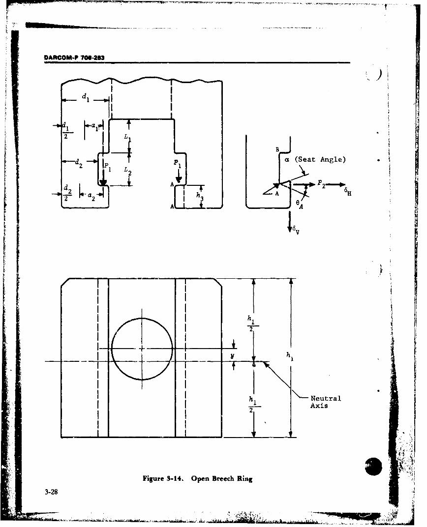
DARCOM-P 706-253
i--w-d a•'
I VV
B
p a (Seat Angle)
/ I L1
_ _
hIITNuta
,, i
i!IFIgur 3-4 pnBec In•
---b a h
I hi
h .Neutral
Figure 3-14. Open Breech Ring3-28
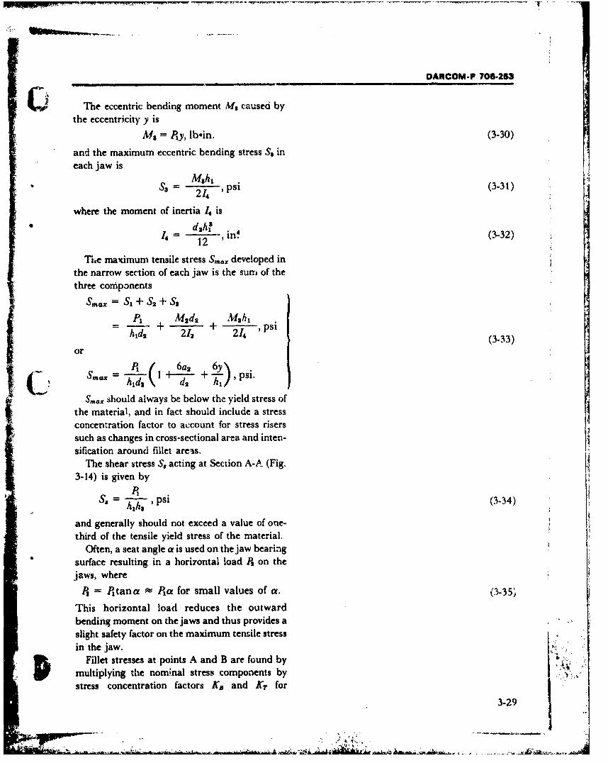
DARCOM-P 706-253
The eccentric bending moment Ms caused bythe eccentricity y is
Ms = Ply, lbein. (3-30)
and the maximum eccentric bending stress Ss ineach jaw is
Ms,hS3 214 , psi (3-31)
where the moment of inertia 1. is
h4 12 , in. (3-32)
The maximum tensile stress S,,.x developed inthe narrow section of each jaw is the suni of thethree coniponents
S=.x SI + S2 + SSP1 Md 2 Mhl
= h--• + 2/ + 2--• 'psihis 212 + 214 (3-33)
or
P, 6a2 6 y\
SS- ax - +-I ,psi.
Sm., should always be below the yield stress ofthe material, and in fact should include a stressconcentration factor to account for stress riserssuch as changes in cross-sectional area and inten-
sification around fillet areas.The shear stress S, acting at Section A-A (Fig.
3-14) is given by
P,SSs ' psi (3-34)
and generally should not exceed a value of one-third of the tensile yield stress of the material.
Often, a seat angle a is used on the jaw bearingsurface resulting in a hori7ontal load P, on thejaws, where
Ps = P~tana se Pta for small values of a. (3-35,
This horizontal load reduces the outwardbending moment on the jaws and thus provides aslight safety factor on the maximum tensile stressin the jaw.
Fillet stresses at points A and B are found bymultiplying the nommnal stress components bystress concentration factors KB and KT for
3-29
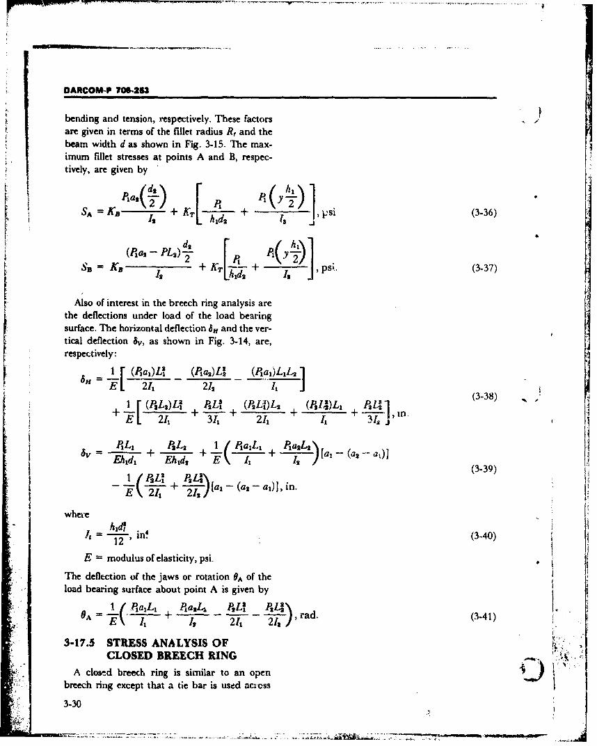
DARCOM-P 706-213
bending and tension, respectively. These factorsare given in terms of the fillet radius R, and thebeam width d as shown in Fig. 3-15. The max-imum fillet stresses at points A and B, respec-tively, are given by [2 P,(~ ](-6F SA=K P + K Isd
,ps+', (3-36)
h~hi
Also of interest in the breech ring analysis arethe deflections under load of the load bearingsurface. The horizontal deflection 6,f and the ver-tical deflection 5v, as shown in Fig. 3-14, are,r respectively:
1 F_________ a2)L (Jll')ILDL P 4) 1 (-
E 21, 212
-- A (3-48)
Th delcto of L22 the jawsL or2 rotatio L1A ofth
1 PAL P2 a,4 1 PaL P,14 L6A += + - )[a,ad (3-41)a,Eh id Id T l' Z 1
33-39
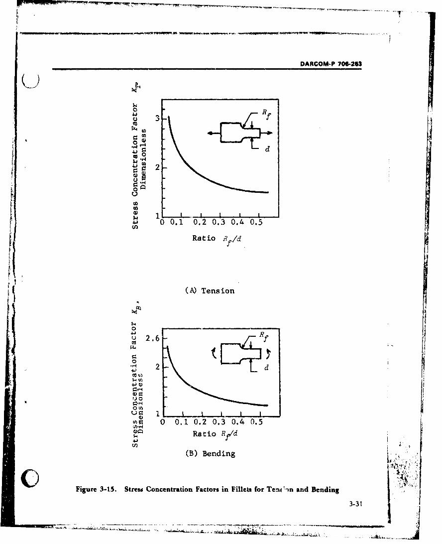
DARCOM-P 706-263
° R
rz4
0 2
0 0.1 0.2 0.3 0.4 0.5
i t'
(A) Tension
0 ,.
o2.6 R
2 t LE§Utd'
0. 0__ J
ch 0.1 0.2 0.3 0.4 0.5Ratio Rf~d
(B) Bending
Figure 3-15. Stress Concentration Factors in Fillets for Tent 'n and Bending
3-31
S, ___... _________ ..--. .• • ,• .•,
DARCOM P M06-253
the jaws (Fig. 3-13(B)) to prevent them froindeflecting outward when subjected to the firingload. The closed breech ring can be idealized asshown in Fig. 3-16. The tie bar is considered as asimple beam that connects the jaws and limitshorizontal expansion.
The external load per jaw PI is taken as half thefiring load. The internal horizontal force P, andmoment MI are found by first computing thefollowing coefficients:
\ ,t T • 1 in.-$ (3..42)
K12 L2- +• ,iin.-2 (3-43)
t Us , in.-2 (3-44)
211 2 12 1, 12 +"s+ •/i.'(3-46)
S3L 12 + L 31 +LIS 1, /x, ')I M2 +3 + I+ 2h,•,_' in.- (3-46)
_[(a, - a,)L'I (a, - a,)LIL]K -a ---- + 11in- (3-4P381 21, 1,
where the lengths LI are defined in Fig. 3-16 and,
I= in (i 1,2)12h~a4
is "-2, in'412
The internal force P2 and moment MI are thengiven by
(KuI-A - K ,K2,u-A• = Ki 'A-2• --'A*12 PI, lb (3-48)
( KsA' \ -- K"21 /P" lb-in. (3-49)
By using P, and MI, the maximum tcnsilestress Si at point E in the figure, the narrow sec-tion of the jaw, is given by
Sic + +- + 2/A + t"A psi. (3-50)h1,-41321241
3-32
AN"
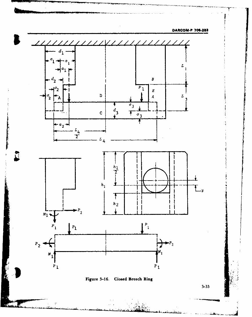
DARCOM-P 706-253
C1=o L
II
,a d2- p d , B,
2 I E
--p - D A L
d L_. __i ' _ C d3 "-F 03
L -
III
hl
hii
-I J~.... tpP
M1{
P P
P1 P'
Figure 3-16, Closed Breech Ring
3-33
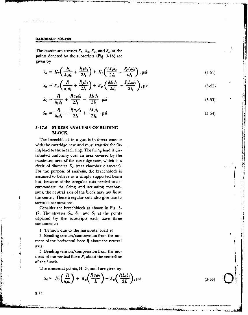
DARCOM-P 706-253
The maximum stresses SA, SB, Sc, and SD at thepoints denoted by the subscripts (Fig. 3-16) aregiven by
SA = KL(h + + KB(M d2 P ,dpd (3-51)\41 d2 214 / 212 412/
SB "-+2 /, +214 ( d2 2 Psi (3-52)
P2 P+a2d3 M 1d3Sc =2 (3-53)
, P2a1d3 M2 d
SD = P2ds 2d + 218- ,'psi. (3-54)
3-17.6 STRESS ANALYSIS OF SLIDINGBLOCK
The breechblock in a gun is in direct contactwith the cartridge case and must transfer the fir-ing load to the breech ring. The firing load is dis-tributed uniformly over an area covered by themaximum area of the cartridge case, which is a icircle of diameter D, (rear chamber diameter).
For the purpose of analysis, the breechblock isassumed to behave as a simply supported beambut, because of the irregular cuts needed to ac- Hcommodate the firing and actuating mechan-isms, the neutral axis of the block may not lie atthe center. These irregular cuts also give rise tostress concentrations.
Consider the breechblock as shown in Fig. 3-17. The stresses SG, Sn, and S, at the pointsdepicted by the subscripts each have threecomponents:
1. Tension due to the horizontal load P2 V2. Bending tension/compression from the mo-
ment of tfi horizontal force P2 about the neutralaxis
3. Bending tension/compression from the mo-ment of the vertical force At about the centerlineof the block.
The stresses at points, H, G, and I are given by
SG= F1, + KB•--")+ , ) s (3-55)
3-34
WO',- .-- ~ -~ - ~ -
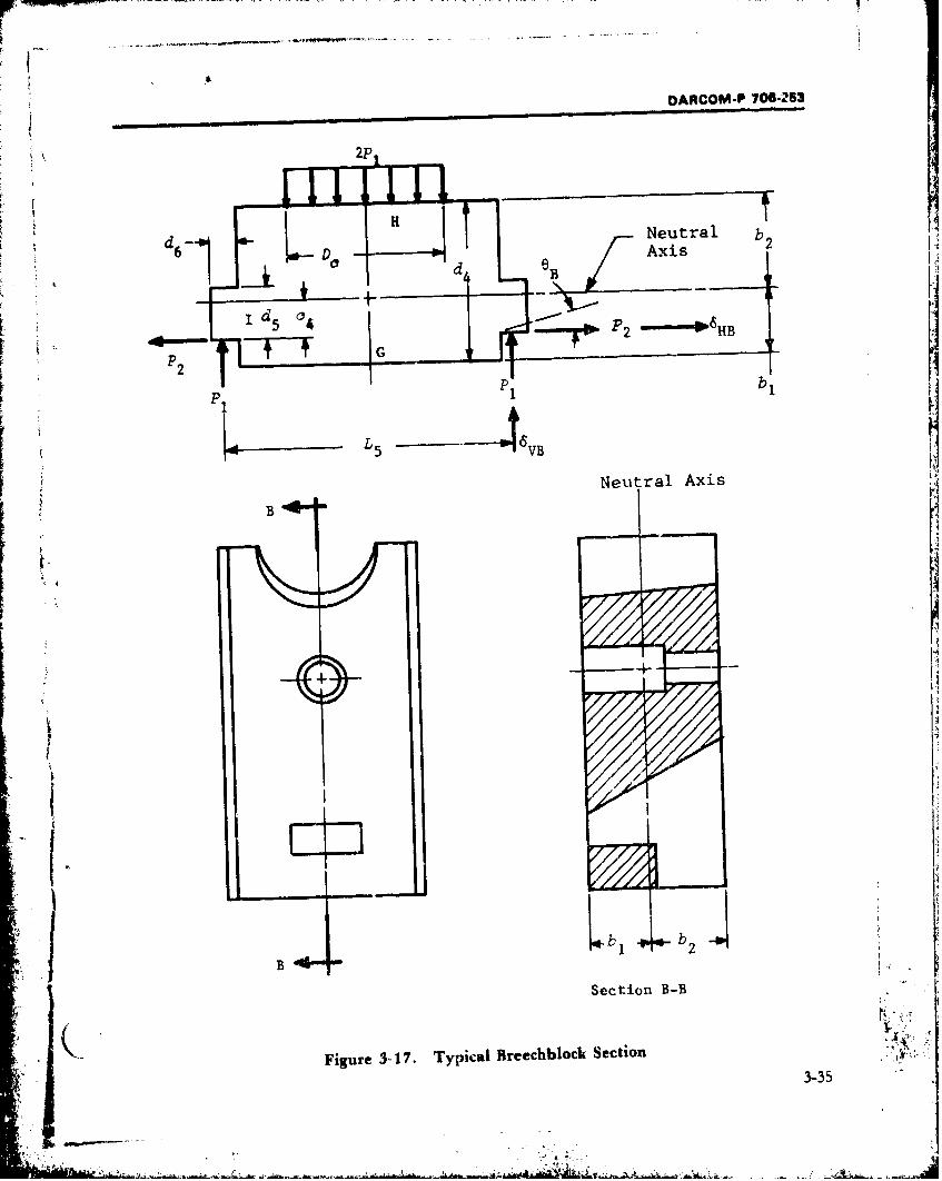
- -
OARCOM-P 706-253
iH
2P2SH Neutral b2
6 Do H AxisH d B
1 d5 04
4 -I--FT- -1
2pG
L 5 1
Neutral Axis
Ii
+ ! , ,
. -T
Section B-B
Figure 3 17. Typical Breechblock Section 3-353-35
OARCOM-P 706-263
Kr Is K,(PsabA KB(PII I
SH'TJJ ' ) K\- - (3-56)hK7 74' (Tr4
where Kr and Ka are stress concentration factorsfor tension and bending, respectively, h, is the ef-fective height of the section considered, and
"it = 0inl (3-58)
The stress concentratioi; factors Kr and K, maybe read from Fig. 3-15, or may be taken a&follows:
t. With holes through G and H
KT = KB = 3.I,
2. With radius R, at I
KT = KB = 0.8/A1 .
The equations for the horizontal deflection6H., vertical deflection 6vB, and angular deflec-tion OB of the load bearing surfaces which contactthe jaws of the bree:h ring are
I_• Ptaj +- P2a42L, 2L6HB = + + P2L1 in. (3-59)
E 214 214 2h4d4 /t ±(+q ,'.,,.:6V, -- E + in. (3-60)
I /PL.' Pa.21 -' 1- + -- , rad. (3-61)SE 1214 214
3.j17.7 STRESS ANALYSIS OF ANINTERRUPTE1)-THR&'AI RLGCK ¶
The exact determination of stresses in circularbreechblocks with intenrupted thread-, such ason the 155 mm howitzcr, is cxtre-oely difficu~lt"from the analytical viewpoint because of the corn-plex geometries and boundary conditions. Tovisualize how the breechblock is loaded, considerthe sectional view shown in Fig. 3-18. The chamn-ber pressure is transmitted by the spindle to theobturator pad which in turn loads thebreechblock. Since the breechblock is threaded
3-36L ~---
DARCOM-P 706-253
"Breech Ring Gun Tube
- I - 'Spindle
If Split
Rin-s
-=-44
iI
i'.BreechblockJ .••
NOTE:
SPINDLE IS FREE rO MOV_ REARWARD WHEN PRESSURE IS APPLIEtENTIRE ENl THRUST 18 TRANSMITTED THROUGH oBITURATOR PAD.
Figure 3-18. Breech Loading Configuration
into the breech ring by means of an interrupted- the block in the four thread-sector areas.
K"L type thread, the end force due to the chamber However, if certain reasonable assumptions are 4
pressure is transmitted as essenially a shec..ing made with rspect to these boundary conditions 1
force distributed over the outer circumference of and geometries, useful predictions can be made.
3-37
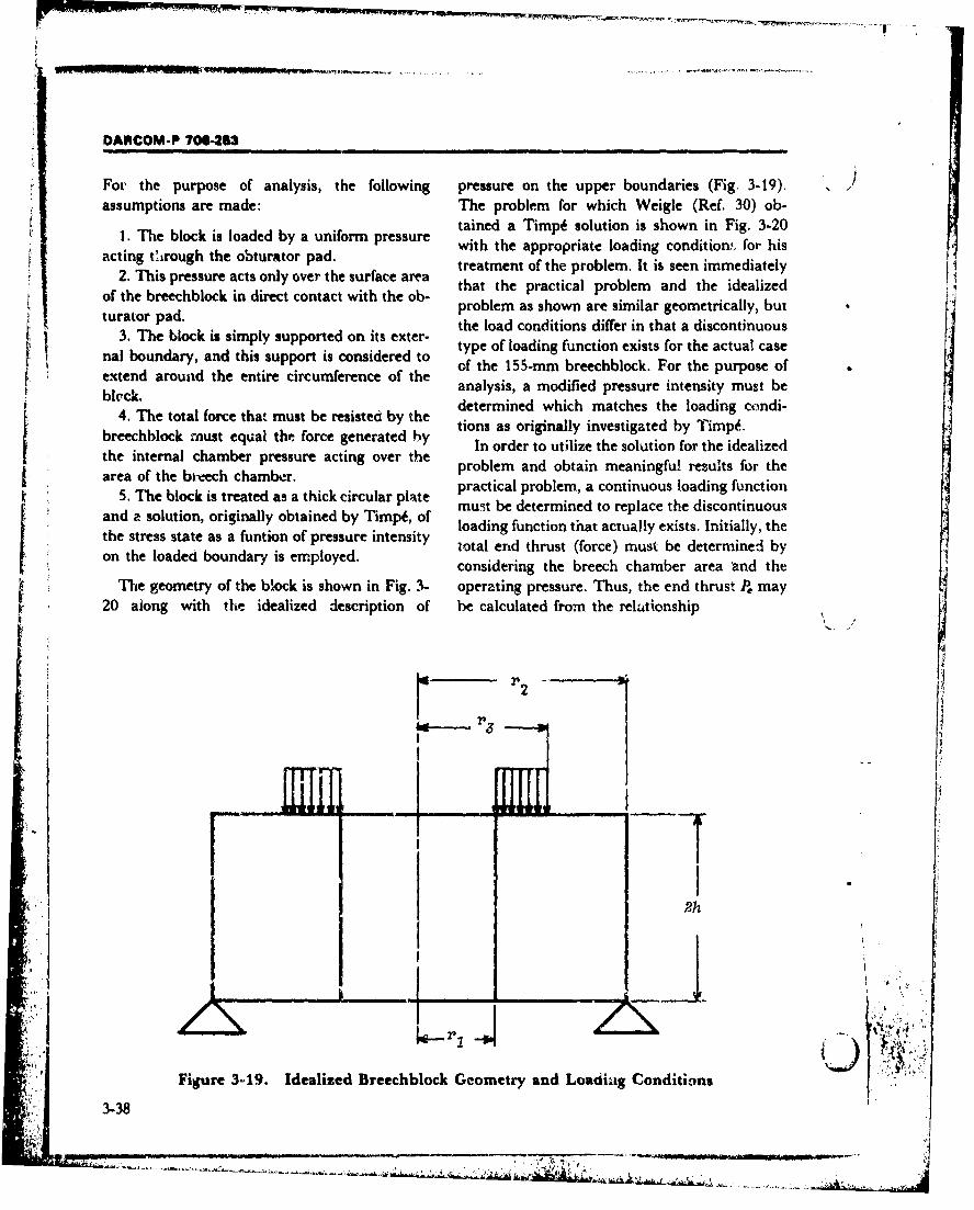
DARCOM-P 706-253
For the purpose of analysis, the following pressure on the upper boundaries (Fig. 3-19). .7
assumptions are made: The problem for which Weigle (Ref. 30) ob-tained a Timpi solution is shown in Fig. 3-20
I. The block is loaded by a uniform pressure ta te appro lu tionis in F igacting trough the obturator pad.with the appropriate loading conditio for his
2.n Tispresure actse onyover tsa ce a treatment of the problem. It is seen immediately2. This pressure acts only over the surface area ta h rcia rbe n h d aiethat the practical problem and the idealizedof the breechblock in direct contact with the ob-
turato pad.problem as shown are similar geometrically, butSturator pad. the load conditions differ in that a discontinuous3. The block is simply supported on its exter- type of loading function exists for the actual case
"nal boundary, and this support is considered to of load function For the auapcseof the 155-mm breechblock. For the purpose of+ extend around the entire circumference of theexten ar teanalysis, a modified pressure intensity must bebleck. determined which matches the loading condi-
4. The total force that must be resisted by the tions as originally investigated by Timp&.breechblock roust equal the force generated by In order to utilize the solution for the idealizedth itena camerpressure atnovrhe problem and obtain meaningful results for thethe internal chamber arssr acting over thearea of the bk-eech chamber.prbe anobanm nigursltfrth
area oThe boistreate d cham r atpractical problem, a continuous loading function5. Tebokitraeasathick circular plate muit be determined to replace the discontinuous
and a solution, originally obtained by Timpi, of l u nctin ta actu tyexist.ntiayuhloading function that actually exists. Initially, thethe stress state as a funtion of pressure intensity total end thrust (force) must be determined byon the loaded boundary is employed, considering the breech chamber area 'and the
The geometry of the block is shown in Fig. 3- operating pressure. Thus, the end thrust P, may20 along with the idealized description of be calculated from the relationship
2 h+
""__"__.... .__...... ..____'_
F I
22h
Figure 3419. Idealized Breechblock Geometry and Loadiag Conditions3-38
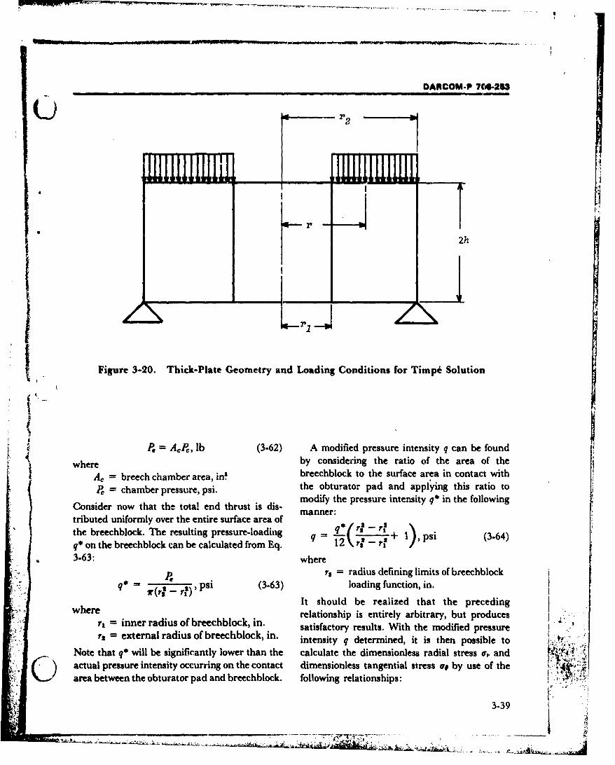
DARCOM-P 7C.-263
III I I II I j
r 2
2h
Figure 3-20. Thick-Plate Geometry and Loading Conditions for Timpk Solution
P, = AP, lb (3-62) A modified pressure intensity q can be foundS where by considering the ratio of the area of theer = breech chamber area, breechblock to the surface area in contact with
P, = chamber pressure, psi. the obturator pad and applying this ratio tomodify the pressure intensity q* in the following, Consider now that the total end thrust is dis- manrmanner:
tributed uniformly over the entire surface area ofthe breechblock. The resulting pressure-loading qq( rf - + p(q* on the breechblock can be calculated from Eq. q = 12 r - r? _ 1), psi (3-64)
3-63: wherers = radius defining limits of breechblock
q (rA - r psi (3-63) loading function, in.
It should be realized that the precedingwhere relationship is entirely arbitrary, but produces
r, inner radius of breechblock, in. satisfactory results. With the modified pressurer2 =external radius of breechblock, in. intensity q determined, it is then possible to
Note that q* will be significantly lower than the calculate the dimensionless radial stress a, andactual pressure intensity occurring on the contact dimensionless tangential stress o, by use of thearea between the obturator pad and breechblock. following relationships:
3-39

DARCOM-P 702U53
r = -3 { [(3 - )(p' - 1) + (3 + ) (W/P') - 4(l -) [V/(#' - I)](lnp)(1/p)
+ 4(1 + so) [#' In (/)-p) )-](P)
- (8/15)1(2 - v)(Ils/ps) - (2 - n)]'J }1(32q)i- , dimensionless (3-65)
a, = -3 {-(3 + ) v)(r + MY'/p) - (5v - 1) + (1 + 3 P)ps
+ 4(1 + ay)[/'/(/' - 1)] (mlB) (1/p3 ) + 4(1 + V) [#a=ln(f/p) - In(1/p)](M - 1)W'
+ (8/15) [(2 - v)(,2/ps) - (2 +v),'] }(329)-1, dimensionless (3-66)
where7= h/r, ratio of half thickness to
inner radius, dimension-less
p = r/r dimensionless radius
= r2/r, = ratio of external radius toinner radius, dimension-less
Orr = Sr/q = dimensionless radialstress
cre = So/q = dimensionless tangentialstress
v = Poisson's ratio, dimensionlessh = half thickness, in.
Sr = radial stress, psiSo = tangential stress, psi.
Eqs. 3.65 and 3-66 are valid for the lower
boundary; i.e., rear face of the breechblock. It is
on this surface that the maximum tensile type
stresses will occur for the loading conditionsspecified. Furthermore, the maximum tangentialstress occurs when r = r,, although the stress may
be evaluated for any given radius r. The stress
computed should be compared to the material
yield strength after proper consideration of stress
intensification and strength reduction factors.
3-17.8 BLOCK-THREAD STRESSANALYSIS
The analysis of thread stresses varies ac-cording to thread type and weapon classificationbut, in artillery design, an evaluation of direct .
shear stress is usually sufficient. (Zr :During firing of a gun, the total force carried
by the threads of a sectored block must equal the
propellent gas force F. where
3-40
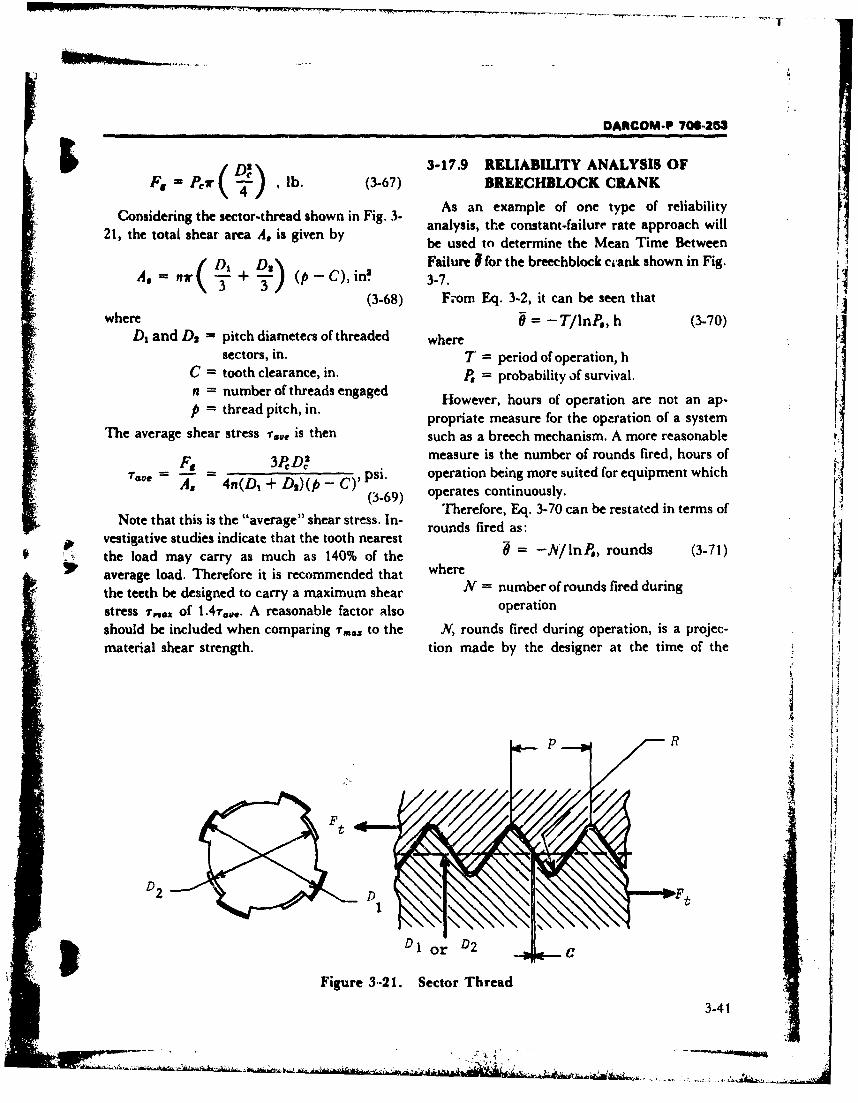
W W t .- r-. IR
DARCOM-P 706-263
/ iDiilI l 3-17.9 RELIABILITY ANALYSIS OFF,= P r -) ,lb. (3-67) BREECHBLOCK CRANKthe sector-thread shown in Fig. 3 As an example of one type of reliability
21, the total shear area A, is given by analysis, the constant-failure rate approach will
be used to determine the Mean Time BetweenS(D, D.3) Failure 1 for the breechblock c'ank shown in Fig.
A, = h T + ) (p -C), in`. 3-7.(3-68) From Eq. 3-2, it can be seen that
where = -T/lnP., h (3-70)D, and D2 = pitch diameters of threaded where
sectors, in. T = period of operation, hC = tooth clearance, in. P. = probability of survival.n = number of threads engaged However, hours of operation are not an ap-p = thread pitch, in. propriate measure for the operation of a system
The average shear stress T..o is then such as a breech mechanism. A more reasonable
F, 3PCD2 measure is the number of rounds fired, hours of
7C A-e 4n(D1 + D=)(p - C)' psi. operation being more suited for equipment whichA. 4(3-69) operates continuously.
Therefore, Eq. 3-70 can be restated in terms ofNote that this is the "average" shear stress. In- rounds fired as:
vestigative studies indicate that the tooth nearest* the load may carry as much as 140% of the 6 = -A/lnP., rounds (3-71)
average load. Therefore it is recommended that wherethe teeth be designed to carry a maximum shear N = number of rounds fired duringstress T,64 of 1.4T.,.. A reasonable factor also operation
should be included when comparing "mox to the N, rounds fired during operation, is a projec-material shear strength. tion made by the designer at the time of the
* p R
F_ ,D2
* Figure 3-21. Sector Thread
3-41
DARCOM.P 708-213
analysis. Thus P., the probability of survivability, whereis the only unknown in the equations and must AT = mean of material strength distribu-be determined in order to calculate 0. tion, psi
In order to determine P., it is necessary to As = mean of stress distribution, psimake calculations concerning the failure of the aT = standard deviation of strength distri-crank. For this purpose, the failure mode for the butionbreechblock crank is postulated to be a material crs = standard deviation of stress distribu-overstress due to bending. The existence of this tion.potential overstress will be dependent on the The mean and standard deviation of strengthgeometry of the crank, the bending load applied, distributions for some commonly used materialsand the characteristics of the material used. As can be found in Ref. 29. The characteristics ofstated in par. 3-15, the fundamental assumption the stress distribution must be calculated,underlying the field of reliability analysis is that starting from the familiar bending stressthe pertinent variables determining the perfor- equationmance of a mechanical system are not single- Mvalued functions. Rather they are subject to a Sb psi (3-75)certain degree of uncontrollable variation, where
The probabilistic distributions of these varia- St, = maxinium bending stress, psitions can be describec' mathematically by a num- M applied bending moment, lbin.ber of general classes of distributions-i.e., Z = section modulus, in!Weibull, normal, gamma, beta, etc. For the pur-poses of the example, a normal distribution will The distributional characteristics of M, the ap-
be used; it is a good fit to the types of distribu- plied momem, can be obtained either through
tions actually found and lends itself conveniently testing or analytical estimation. If estimation is
to calculations. used, the designer should bear in mind that this
The characteristics of any normal distribution is a crucial factor in the reliability calculation,are completely defined by two parameters-the and special care must be taken to ensure that themean (average) de of the distribution and the estimation is as accurate as possible.meand(averdde)n p of the distribution.y a ond tThe distributional characteristics of the sec-standardtion modulus Z can be calculated from the dis-vention, these two parameters are represented as(JL, u). This convention will be used throughout tributions of piece-part dimensions. Assume thethe discussion that follows, cross section of the crank to be rectangular, as
shown in Fig. 3-23; then the classical (non-The probability of survival P, will be deter-
mined through the use of Fig. 3-22. Inspection of probabhstic) equation for the section modulus is
the figure shows that three ratios must be Z 6calculated and used as inputs to the process- - - in6 (3-76)
where the symbols are defined in Fig. 3-23.
FS - A-T (3-72) However, in order to be of utility in a reli-As ability analysis, it is necessary to dttermine the
distributional characteristics of the section(ratio)s as (3-73) modulus variable. The mean uz of the distribu-
AS /tion for the section modulus Z is rather(rati~s = 373) straightforward
(ratio)T = (3-74) A- 6 in. (3-77)AT 6
3-42
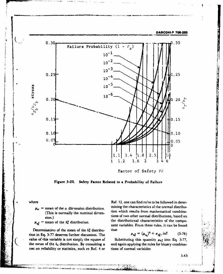
DARCOM.P 706-2630.3C -I i• I =• -- I
.30 .30Failure Probability (1 -
.3)
i0-I
-210-2._
10-3
K0.25- C.2510-
I5
0 10
Si-6
0.15- F o 0.15
0.10- 0.10
0 .5 Q 0.05"-n 00 :, 0
"1. 1.4 .1. 2. 1
1 1.2 1.6 26
S~Factor of Safety FS
Figure 3-22. Safety Factor Related to a Probability of Failure
where Ref. 12, one can find rules to be followed in deter-Smean of the u dirr'ension distribution, mining the characteristics of the normal distribu-
(This is normally the nominal dirnien- tion which results from mathematical combina-
sion.) tions of two other normal distributions, based onmean of the h, distribution, the distributienal characteristics of the compo-
nent variables. Fromn these rules, it can be foundDetermination of the mean of the h? distribu- that
tion in Eq. 3-77 deserves further discussion. The g4= (M,,)' + Og, in'i (3-78)
value of this variable is not simply the 2quare of Substituting this quantity Ajq into Eq. 3-77,the mean of the hg distribution. By consulting a and again applying the rules for binary combina- ' Jtest on reliability or statistics, such as Ref. 4 or tions of normal variables
3-43
•D .............. -~ ~~~~* .-' - N • ,. ... . . . . ...
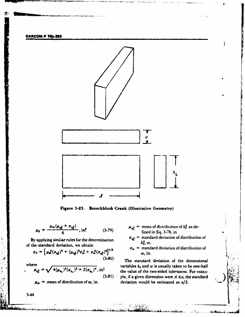
Li
- ___ I
" " -- AACOM-P VOUl-MI
11
6 (3-79) fined in Eq. 3-78, in.
By applying similar rules for the determination sta, ndadd. aino itiuinoof the standard deviation, we obtain 6 I40 i tn.addvaino itiuino
0,1 jg)'oJ. + OuJ(crie)']1 w, stndaddvaino.itiuino
(3-0) The standard deviation of the dimensionalwhere variables h4 and w is usually taken to be one-half
,m - ,
iureh 3-e. valeut e of the tw-sidoe tolelurces. ForGeomtean• of d o o, in.S (3-81) ple, if a given dimension were A +a, the standare
S ean dition wdeviation would be estimated as a/2.
3-44
o'• [p(¢•) + .u•S~rw + ,,(•)m]/* w : tanarddevitioofdstriutin o
I "DANCOM-P 706-253
W Having determined the distributional charac- FS - 1.8, (1 - P.) is approximately 10-. Solvingteristics of Z, it is now possible to calculate the for Pq, we obtain the probability of survival ascharacteristics of the bendir, stress S. By using 0.999.the combination rules applying to division: By using the value of P. determined as shown,
( and substituting into Eq. 3-71, it is now possiblefA, -W ± psi (3-82) to determine F, the Mean Time Between Failure
for the breechblock crank. If P, - 0.999, and N isgoo #I(au,)a 11/s assumed to be 10,000 rounds,
Us. - '• pi +• I I ,s+ = -10,000/In(0.99 9 )
The necessary parameters having been deter- -
"mined, it is now a simple procedure to use Fig. = 9,994,999 rounds.
3-22. First calculate the three indices for the Components, subsystems, and materials whichgT have demonstrated field reliability should be
graph, usd-vand eNext construct a lineits As's, A"rT used whenever possible. This will increase the
connecting the points on the vertical axes corre- probability that these items will be reliable in thesponding to the calculated values, as shown on new design. Designs which are "at a limit of ex-Fig. 3-22. At the point where this constructed perience" rhould only be used when this isline intersects the vertical FS-line, interpolate necessary to achieve a specific requirement. New
_x•-between the curved (I - P.) lines to determine systems or components should be subjected to
(1 - P.) for this design. For the example shown accelerated life and environmental testsOr owhenever possible at part of the design develop-' ' on Fig. 3-22, with T-, =0O.M and --b = 0.20, if
orFit . nd 02, ment and reliability demonstration.
SECTION IV. PROTOTYPE TESTING
3-18 GENERAL CONSIDERATIONS The planning of tests is one of the most signifi-
Testing is a maj-or element of an overall design cant aspects of prototype development after theprocedure for breech mechanisms. Prototype initial concept is evolved. Test plans elect ortesting is an investigative process, simulating a define the problem area for investigation, selectdesired operational environment. It is employed the model configuration, describe the operational"to challenge the fundamental design charac- and environmental exposure, and determine theteristics of the breech mechanism such as required instrumentation system (Refs. 20 andstrength, operational interface, and function. 21).Prototype testing is p'rformed to identify design Further discussion of breech mechanismdeficiencies requiring redesign (Ref. 19). testing is given in Chapter 4.
Successive iterAt•ons of the design/test cycleshould produce models of improved behaviorwhoe characteristics cr potential characteristics 349 MODELS"will meet or exceed the required criteria or Upon completion of the test plan, the area ofspecifications of model perform&nce. Instances investigation and the breech nwodel charac..
41occur, however, where performance criteria may teristics will be defined. The mod •,nfigurationS not be satisfied for a model design due to spatial, will vary from fairly simple pressure vessels, toU mechaniatic, and material constraints; program detailed plastic models for photoelastic verifica-
redirection is then required. tion or determination of stresses, through
3-45
DARCOM-P ?7W253_
wooden mock-ups for machine function or The breech prototype firing model is con-human response to full-scale models for firing structed to verify the operational design premiseand operational tests (Refs. 22 to 24). arnd evaluate long-term trend effects, The breech
The mock-up is used to illustrate concept and subsystenm usually is incorporated in a functionaldemonstrate handling. Another function of the firing model of the weapon system. Somemock-up is to provide a three-dimensional variance may occur in weapon model corn-visualization of design for the purpose of verifying pleteness for features which are not required dur-or allocating spatial assignments. The mock-up ing actual firing-such as roadability andis used extensively for problems related to human automatic loading.engineering factors. The model is used to verify load distribution,
Dependent upon the purpose they serve, mock- handling, and to determine long-term effectsups will vary in operational detail from no from questionable stress concentrations, newrelative motion to a complete mechanistic material processing, and manufacturing tech-replication of the handling functions. niques.Breechblock design and closure, chamber design,automatic versus manual design features, loader- 3-20 PERFORMANCE SIMULATIONrammer interaction, manufacturing ,echniques, TESTSand external configuratirn are some of the pur- Two test machine systems exist for actuatingposes which may best be illustrated by a system artillery and breech subsystems which may bemock-up. considered for use in lieu of designing special
Another series of models which are available to purpose equipment or using firing tests. One, thethe designer is constructed to d,-termine, verify, gymnasticator, provides a good simulation of theor upgrade operational and structural rharac- recoil cycle without the necessity of firing projec-teristics of new design features. The models are tiles ard may be employed to test or tvaluateconstructed to transmit both static and dynamic breech unlocking, opening, ramming, loading,loads through model materials that physically etc. These devices are located principally at Rockrespond in a manner that is relatable to can- Island Arsenal. Additional information fordidate design materials. The degree of simulation design or availability can be obtained from theis quantified in terms of response so that US Army Armament Research and Developmentengineering credence is maintained when test Command, Dover, NJ (Ref. 26).data are translated to design requirements. Another is the cannon breech mechanism
The nonfiring prototype models are test testing machine. Two of these were designed anddevices employed to investigate load distribution developed by Watervliet Arsenal for use with the(especially stress concentrations) and fatigue life, 175 mm Ml 13/MI13EI Gun and 8 in. Howitzer,and may be used to evaluate operator loads. The M2AIE1. The system is capable of reproducingmodels usually simulate a specific function such the pressure-time signature of most gun firingas breech closure or sealing, or a design charac- pressures up to 75,000 psi. The system requires ateristic such as strength and ease of loading. A capped stub tube to close the tube end of thedifferent model may be required for operator breech and seal off the firing mechanism cavity.oads which would simulate the dimensional and Provision also must be made to obturate theinertial characteristics of the breechblock and breech to prevent initial oil leakage. Cyclicalbushing interface. The spatial constraints of the studies for fatigue or life estimates can be con-carriage and auxiliary equipment could then be ducted with this equipment. Additional informa.-constructed as a mock-up where dimensional tion is available at the Benet R&E Laboratories,authenticity is needed but only nominal struc- Watervliet Arsenal, Watervliet, NY (Refs. 27 andtural response is required (Refs. 22, 23, and 24). 28).
3-46

DARCOM-P 700-253l I • I I I ii[I( - _ . . . .
REFERENCES
t. AR 1000-1, Basic Policies for Systems Acquisition 16. R. P. Haviland, "Reliability in Guided Mis-by tsk De1parttnet of the Army. siles", jet Propulsion, July 1971.
2. S. Timoshenko and D. II. Young, Elements of 17. C. Lipson, Interference Theoryfrom the F iepoint,. tStrength of Materials, D. Van Nostrand Com- of Safety Factor, University of Michigan, Ann
pany, Inc., Princeton, NJ, 1962. Arbor, MI, 1967.3, DARCOM-P 706-193, Engineering Design 18. AMCP 706-192, Engineering Design
Handbook, Computer Aided Design of Handbook, Computer Aided Design ofMechimical Systems, Port Two. Mechanical Systems.
4. Lloyd and Lipow, Reliability, Management, 19. AR 70-10, Test and Evaluation During Develop-Methaodr, and Mathematics, Prentice-Hall, Inc.. ment and Acquisition of Materiel.Englewood Cliffs, NJ, 1962. 20. Col. F. King, "Product Assurance Sym-
5. AMCP 70-9,Engineering Design5.M 706-196, Eng i Dposiure Technical Report (AcquisitionHandbook, Development Guide for Reliability, Guidelines on Test and Evaluation,
Part Two, Design Jor Reliability. USAMC)", American Ordnance Association,6. AMCP 706-197, Engineering Design 1972.
tHandbook'T , l yDeveopmentiGuide for Reliabiy 21. F. B. Pollard and J. H. Arnold, Jr., Aerospace
ReiOrdnance Handbook (12 Test and Evaluation),7. AMCP 706-198, Engineering Design Prentice-Hall, Inc., Englewood Cliffs, NJ,
Handbook, Development Guide for Reliability, 1966.A Part Four, Reliability Measurement. 22. J. W. Daily and W. F. Riley, Experimental
8. AMOP 706-200, Engineering Design Stress Analysis, McGraw-Hill, Inc., New
Handbook, Development Guide for Reliability,Part Six, Mathematical Appendix and Glossary. 2P
9. Reliability Engineering, ARINC Research 23 A. J. Durelli and V.JParksMoireAnaly's° oICorporation, Prentice-Hall, Inc., Englewood Strain, Prentice-Hall, Inc., Englewood Cliffs,
Cliffs, NJ, 1964. NJ, 1970.10. C. Lipson, Engineering Applications of 24. Design of Breech Mechanism, A Symposium
Reliabilit, University of Michigan, Ann Ar- Ordnance Project RI-10OL, Franklin Institute,
bor, MI, 1963. °Philadelphia, PA, 1969.
11. E. Pieruschka, Principles of Reliability, 25. Harris and Crede, Shock and Vibration
Prentice-Hall, Inc., Englewood Cliffs, NJ, Handbook, McGraw-Hill, Inc., New York,
1963. NY, 1961.
12. E. Barlow and F. Proschan, Mathematical 26. Future Artillery Test Requirements by the Test Fa-
Theory of Reliability, John Wiley and Sons, cdties Committee, ART-469, USAWECOM,
New York, NY, 1965. R&D Directorate, Artillery System
13, "A Manual of Reliability", Product Engineer- Laboratory, Rock Island, IL, August 1969.
ing Special Report, Morgan Grampian, Inc., 27, The Design and Construction of a Cannon Breech
New York, NY, 16 May 1960. Mechanism Testing Machine, WVT-QA-6902,14. D. N. Chorafas, Statistical Processes and Re- Watervliet Arsenal, Watervliet, NY, 1969.
liability Engineering, D. Van Nostrand Com- 28. Determination of the Fatigue Life for the Breechpany, Inc., Princeton, NJ, 1960. Mechanism Assembly for the Cannon, 175 mm Gun, ,
15. E. A. Felsted, "Product Reliability", M113 and M113A1, WVT-7108, Watervliet
- ( ,Ordnance, (November-December 1971). Arsenal, Watervliet, NY, 1971.
3-47

IDANCOM-P 0"63I
�b - *FEIRENCZS (coutd)
29. E. B. Haugen and D. H. Mutti, Statistical 'f Strains in Breechblock Components ofMetals Menual, University of Arizonp Large-Caliber Weapons", Proceedings of theTucson, AZ, 1973. Society for Experimental Stress Analysis 21
30. R. E. Weigle, "Dynamic and Static Analysis (1964).
i BIBLIOGRAPHY
AR 70.38, Research, Deveopment, Test, and Evalua- T.G. Beckwith and N. G. Buck, Mechanicaltio of Materiel for Extreme Climatic Conditions. Measurements, Addison Wesley Publishing Co.,
MIL-STD-810, Environmental Test Methods. Inc., Reading, MA, October 1961.MTP 3-2-807, Materials Testing--Nondestructive ISA Transducer Compendium (Instrument Society of
Examination, AD-717 372. America) IFI/Flenum Data Corp., subsidiaryMTP 3-2-809, Strain Measurement-Brittle Lacquer of Plenum Publishing Corp., 227 West 17th
Method, AD.717 374. Street, NY, 1969.MTP 4-2-805, Projectile Velocity Measurements, AD- MTP3-2-810, Weapon Pressure Instrumentation, 1966,
872 645. AD-717 376.MIL-STD-831, Preparatioi, of Test Reports. C. C. Perry and H. R. Lissner, Strain Gage Primer,MTP 3-2-500, Weapon Characteristics, 1971, AD- McGraw-Hill, Inc., New York, NY, 1962.
726 909. MTP 3-1-006, Strain Measuremeni-Instrumental,MTP 3-2-509, Artillery Cannon, 1970, AD-718 833. AD-876 179.MTP 3-3-510, Weapons Functioning, 1969, AD-867 G. A. Jones, High Speed Photography, John Wiley
236. and Sons, New York, NY, 1952.FSTC-HT-23-928-68, Preparation of Artillery MTP 2-2-800, Center of Gravity, AD-717 506.
Weapons for Firing, Translated (USSR), 1962, MTP 3-2-800, Inspection and Measurement ofAD-688 058. Cannon, AD-718 709.
3 - (
(21
-•. 3-48
DARCOM-P 706-253
CHAPTER 4DEVELOPMENT CRITERIA AND PROCEDURESSECTION I. DEVELOPMENT EVALUATION PROGRAM
4-1 GENERAL CONSIDERATIONS and a description of the tests which were per-SThe path of development of ordnance equip- formed. Thus the test report could serve not only
ment from prototype to final product and serial to detail any successes or failures but also to es-manufacture is long and complex. A number of tablish a body of information which can be usedthe activities that take place during this phasc re- as a reference source by the design team cur-late directly or indirectly to breech design. The rently involved in the development of the breech
failure of the weapon system in certain of these mechanism, as well as by future groups who use
activities may necessitate redesign of the breech the reports for data bank information.
and, therefore, an understanding of the com- The types of tests to be conducted - as well asplate development procedure will benefit the de- the distribution of responsibility for the various
signer. The objective of this chapter is to provide tests among design, evaluation, and user agenciesthe designer with an overview of the complete - will change from weapon system to weapon
process. system. Details of the specific types of tests, as
The procedure from initial design specifica- well as guidelines for their application, are found
tions to acceptance of initial serial manufacture is in AR 70-10 (Ref. 1) and will not be discussed in
characterized by a number of specified design this handbook.
testing phases. In addition, internal devel- 4-1.2 EXTERNAL INFLUENCES= opment testing is conducted as required.pt nrThe breech mechanism, being a subsystem of a
larger weapon system, cannot be designed in-4-1.1 TESTING dependently of the other subsystems. While it is
For breech mechanisms, as for all mechanical far beyond the scope of this handbook to con-systems, physical testing is an essential part of a sider all possible influences on the breechdevelopment program. While the test programs mechanism design which may come into play,have the obvious result of demonstrating suc- there are two areas which have enough effect thatcesses and pinpointing -failures, a coordinated they cannot be ignored.test program has a 3econd, less obvious role with- The first of these areas of influence is the typein the development cycle, which should be made of ammunition to be used in the weapon system.clear at the outset of this discussion. For conventional ammunition, the breech de-
The development cycle can be viewed as a velopment can proceed through standard pro-series of actions which are targeted to pass a gression. However, development for the use ofseries of test milestones. As a direct result of this ammunition which is substantially different fromfact, test reports are a perfect vehicle for amass- prior models (as with the introduction of missileing complete documentation of the development launching capability on the 152 mm gun/process. Test reports are generated which con- launcher) will require, well in advance of a for-S tain a statement of the test objectives, arcom- mal test prototype, the design and fabrication ofplete description of the item being tested (by in- a breech mechanism which will incorporate thecluding drawings, material specifications, etc.), new features mandated by the predictions for the
4-1
DARCOM-P 706-213
new ammunition. It is conceivable that this ac- lation testing is no exception to this rule, and • )tion will be required even before ammunition some of them are discussed in the paragraphsparameters have been fully established and may that follow. The points discussed are not in-serve as inputs to the ammunition design. This is tended to be an exhaustive list; indeed, they area clear departure from the usual progression of intended primarily to make the designer awaredevelopment and places an additional burden on that there are shortcomings in the simulation ap-the design team. However, it presents an oppor- proach and to give him z. starting point fromtunity to obtain early test results on the appli- which he can begin his own evaluation of thecable components. benefits of simulation. Consideration of' these
A second external source of potential change is possible shortcomings should be incorporatedthe gun tube. Should the tests of the tube dictate into the test plan.a a change in the tube design, which in turn The principal shortcomings lie in the pro-changes the breech ring configuration, a change pellant charge simulation. As mentioned pre-to the breech mechanism design is a likely re- viously, this simulation duplicates the time-suit. The existence of this possibility should be pressure signature of the proposed propellanttaken into consideration when establishing de- charge and is used to test the strength/fatiguesign and testing schedules. characteristics of the breech mechanism. How-
ever, due to the way in which the pressure, load-4-1.3 SIMULATION TESTING ing is applied, this test does not simulate the re-
Simulation testing is a capability which has coil-counterrecoil accelerations experienced bycome into use for testing gun systems within the the breech mechanism in service. Further, thisrecent past. The two major advantages of simuia- test does nothing to simulate the temperature ortion testing are the reduced time and expense in- chemical environment encountered during ser-. ,
curred in achieving the required number of test- vice. It is fully possible to simulate each of thesefire cycles, as compared with conventional proto- effects in the laboratory environment. However,type testing. it is extremely difficult to apply them concur-
At the present time, there are two types of rently. This fact should be taken into con-simulation testing which are used on breech sideration during the planning and evaluationmechanisms. The first of these is a propellant- stages of testing.charge simulator which can duplicate the time- Breech mechanism gymnastication testing alsopressure loading characteristics of the proposed has one major shortcoming - i.e., the method ofammunition (Ref. 2). The test is used to assess application, as was the case with ammunitionthe strength and fatigue adequacy cf a proposed simulation. When the mechanism is tested on thedesign. gymnasticator, the loads and motions applied are
The second type of simulation often used is one those which the designer considers "proper".which repeatedly and automatically opens and Unfortunately, these limits do not necessarilycloses the breech mechanisrn (referred to as gym- correspond to the use profile to which thenastication). This simulation can be used to de- mechanism may eventually be subjected.termine the acceptability of the performance of As a result of the preceding comments onthe mechanism as it degrades due to wear of the simulation testing shortcomings, one pointcomponent parts. For more information con- should by now be clear to the reader; simulationcerning the specifics of these tests, the reader is testing can be used to supplement, but not toreferred to par. 3-20. supplant, firing tests. Due to their time and cost
For almost any testing approach, the premium advantages, simulation tests should still be con-paid for strong advantages in some areas is the sidered a valuable part of the overall testexistence of shortcomings in other areas. Simu- schedule. However, actual firing tests should still
4-2
I.. ... .. 2.
DARCOM-P 706-253
( be considered as a final check on the results and progresses. Such problems may, in addition,
conclusions gained from the simulation tests. necessitate redesign or modification of othercomponents in the weapon system. The para-
S4-1.4 ENG•INEERING TEST/EXPLNDED graphs that follow summarize some of the prob-SERVICE TEST (DT-2) lems that may be encountered. Due to the corn-
When the weapon has been redesigned and de- plexity of the breech mechanism, an individualbugged using data obtained during Develop- treatment of the potential problems is beyond the"ment Suitability Tests (DT-1), Refs. 2-5, an scope of this handbook. However, by highlight-average of from I to 20 engineering prototypes ing some of these problems, it is hoped that anyare fabricated with materials, manufacturing design team will see the necessity for carefulprocedures, and tolerances as close as possible to analysis of a proposed design in order to an-those to be used in finai manufacture. These ticipate and eliminate potential problems at asprototypes are used to develop data on solutions early a stage in the development cycle as pos-to the problems detected during DT-1 and to en- sible.sure that no new problems have developed.Usually one or two prototypes are used for in- 4-2.1 MECHANISM MALFUNCTIONS
ternal firing and laboratory testizig by the manu- Mechanism malfunctions include prematurefacturer. The remaining weapons are used in failure or unusual wear of the breechblock,field tests which are conducted at test sites lo- breeci ring, latches, operating lever assemblies,cated at Aberdeen Proving Ground, MD; Yuma counterbalance mechanisms, extractorProving Ground, AZ; Panama Canal Zone; and mechanism, firing mechanisms, breech closureAlaska. threads, and sliding surfaces. Component failure
includes breakage, cracks, excessive strain (de-S 4-1.5 INITIAL PRODUCTION TESTS formation) causing poor or unreliable function-
(DT-3) ing or 3eizure, galling or pitting of moving parts,
Sample weapons from the initial production weakening of springs, excessive leakage, forma-run are used for Government field testing. These tion of burrs, pitting, excessive rusting, and cor-tests are necessary to ensure that the production rosion or wear resulting in unsafe or unac-weapons function satisfactorily and that no new ceptable operation. In most cases, minor modifi-problem areas have benti :ntroduced by manu- cations such as change of material, surface finish,facturing technique modifications (from proto- heat-treatment, and fillet radii will eliminatetype to production manufacture). Normally, no many of these problems. In other cases, minor oradditional internal testing by the manufacturer is even major redesign is necessary.required during this phase unless deficiencies arndetected. For a more detailed discission, the 4-2.2 DESIGN DEFICIENCIES
reader is referred to Refs. 2-5. Deiign deficiencies relate to the inability of thebreech system to perfoi'n satisfactorily when all
4-2 PROTOTYPE DESIGN components are operating as designed. These de-DEFICIENCIES ficiencies include improper interaction with other
Most of the design-related problems as- system components such as recoil or loadingsociated with a new breech mechanism will be mechanisms; the poor design or placement ofdetected during the testing described in par. 4-1. operating handles or levers that cause awkward,It is extremely important that such difficulties be unnatural, or excessive force by the weapon
Sdetected as early as possible in the development operators; insufficient space to load, unload, orcycle since correction becomes increasingly cost- operate the weapon; poor access to primer l•.ly and time-consuming as development loading parts that require removal of gloves in
4-3
DARCOM-P 706-2U5
cold weather; difficulty in operating the weapon or cost, the design agency must make ap- )at extremesL of elevation or azimuth; other mal. propriate recommendations t ý. the contracting of-function or failure of components when sub- ficer and project manager who have the re-
jected to unusual stresses during firing or trans- sponsibility for authorizing contract changes.port; and failure to protect components from the During this phase, other design refinementsenvironment because of ineffcctive shields or not included in the prototype weapon must becovers, poor design, or allowing pockets, corners implemented. These may include provisions forI or exposed threads to accumulate water, dirt, lifting points for assembly/disassembly duringdust, mud, or firing residue during storage, maintenance, and complete implementation oftransport, or operation. the human factors analysis. The weapon analysis
The effectiveness of design trade-off (e.g., the should be completed and the required manu-necessity of protecting the obturator pad and facturing processes, material specifications,rings during loading as opposed to the de- quality assurance requirements, and initial pro-sirabiiity of having them exposed for easy visual duction planning reviewed. This is, of course, ainspection and maintenance) also will be de- team effort and it is of vital importance that alltermined during the testing phases and will pro- team members be kept informed of develop-vide additional feedback to the designer for use in ments affecting their roles and be given an op-redesign and debugging. portunity to contribute to decisions. Formal
design reviews that provide documentation andcontrol on a systemized basis are recommended
4-2.3 MAINTENANCE to maintain optimal program coordination andThe designer should strive to eliminate main- progress. This subject is covered more complete-
tenance altogether by using sealed bearings or ly in Ref. 6.
bearings requiring no lubrication, lubricated andse;led gears and chains, etc. If these are not pos- 4-4 ACCEPTANCE:sible, modular subassemblies, which can be easi- ENGINEERING/SERVICE TESTSly and rapidly replaced in the field using avail- All testing, whether of the programmed (DT)able or, pre-eably, no tools, are recommended. or special purpose type, comprises three distinct
phases:1. Before-fire checks and preparations
4-3 DEVELOPMENTAL REDESIGN 2. Firing testsSPHASES 3. After-fire checks.
Responsibility lies with the design agency for Beyond this general breakdown, the programscorrecting the design and implementing the are tailored to the specific requirements of thechanges shown to be necessary by the test data sought. To illustrate, a representative test *
phases. It is, however, important to consider the program will be described for a test series used toeffects such changes will have on other parts of proof the 105 mm, M68 Cannon used on thethe weapon system; e.g., the crew, development M60AI Tank.and testing, production scheduling, and the cost Fig. 4-1 shows a work flowchart used to proofof the program. Changes that affect the re- the first three units manufactured under a newsponsibilitie, of other members of the project production contract. Subsequent productionteam should be documented and transmitted to units are tested using an abbreviated version ofthose individuals as soon as possible. If changes the proof tests (Fig. 4-2). The breech mechanism "are significant enough to alter project scheduling portions of these proof-test procedures follow.
4-4
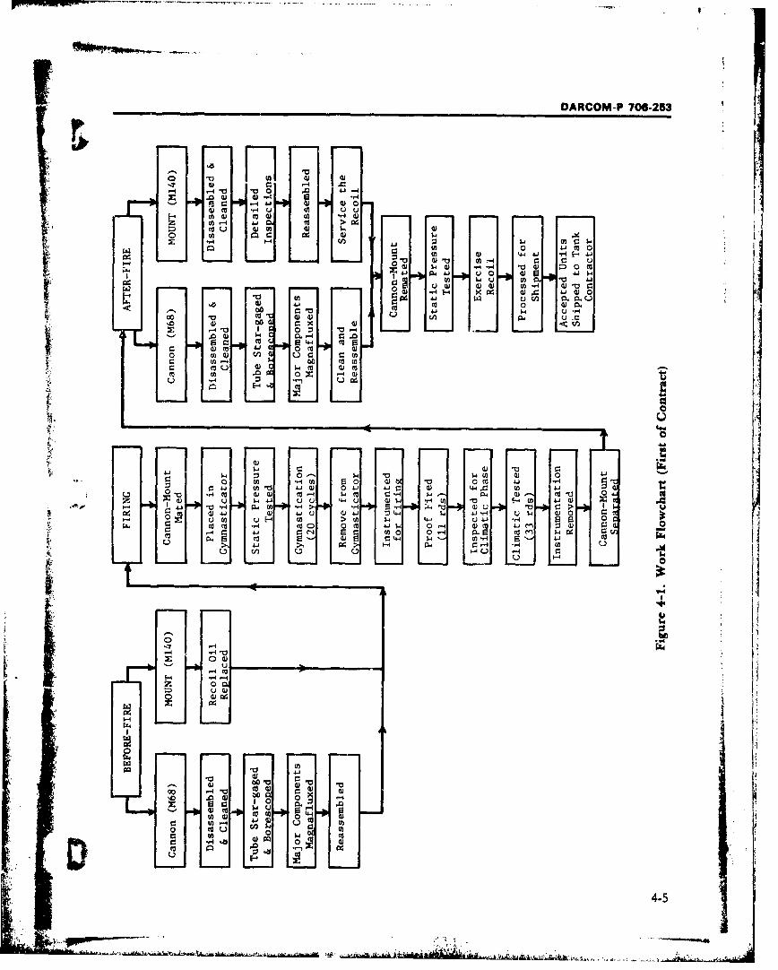
VDARCOM-P70-5
W 0-
-I. 4a I 0. ~ .a
0 J-104-4 AJ (1 A
4) 4i 0 :)u 0. Z .4
w2 04 (v 0
~~ 4-J44
IA c 10 00 4
00 x Ln
10 0~ z 4-4 .
0 -( 4)4 04 w-i A~. u- 0 4) 0Ar_ W4~ P.4- S,-21 00 mU 4.1
cc 0 Q) ~ -
E4 4 u
-44
$4 0
WDI 0 w-4-L) $4 tf
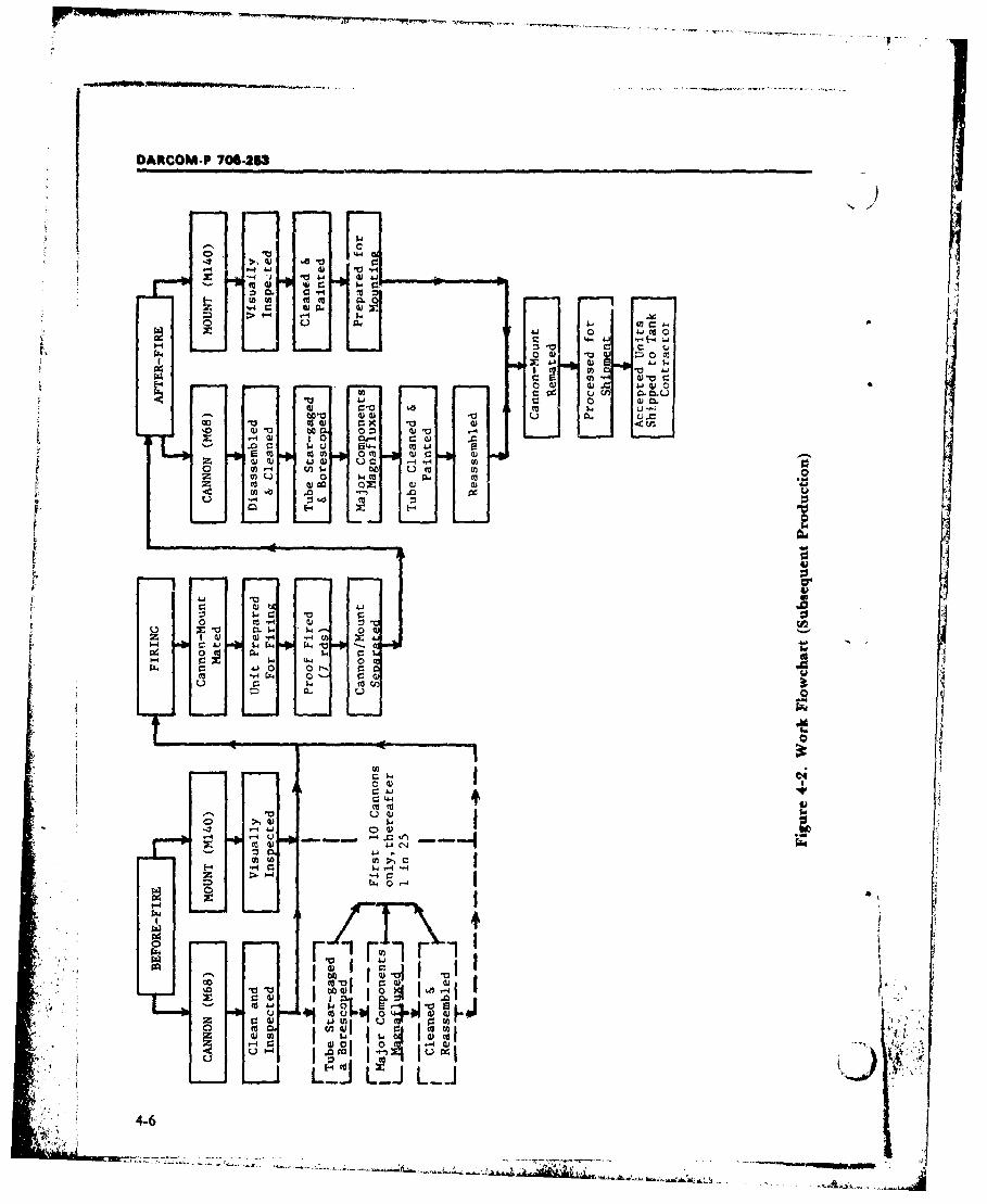
DARCOM-P 704263
-4 41 po )to~, 0) w
44
4) q3 to a 0 m 4)4)toi 4- 00 m w
z 9) ýJv ,4C) u .X H V
f-. KA -40 O- m E
E-4
tt -H 4) :1 "c-
:L'.
r- 0VU .
Coo 11
U0 4J C
>1-U-4
U)- U)- U)f-4 "w r. q H
*~ 1~ L L..J
LLJ
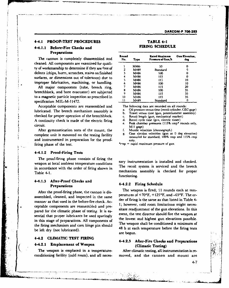
DARCOM-P 706-253
4-4.1 PROOF-TEST PROCEDURES TABLE 4-1
4-4.1.1 Before-Fire Checks and FIRING SCHEDULE€ Preparations
PRound Rated Maximum Gun Elevation,
The cannon is completely disassembled and No. Type Pressure of Gun,% deg
cleaned. All components are examined for quali-ty of workmanship to determine if they are free of 2 M489 Stanard
defects (chips, burrs, scratches, stains on finished 3 M486 100 0surfaces, or dimensions out of tolerance) due to 5 M486 115 00
5 M486 115 10improper fabrication, machining, or handling. 6 M486 too 10
All major components (tube, breech ring, 7 M486 115 208 M486 100 35breechblock, and bore evacuator) are subjected 9 M486 115 35
to a magnetic particle inspection as prescribed in 10 M486 115 35
specification MIL-M-11472. 1I M489 Standard 0
Acceptable components are reassembled and The following data are recorded on all rounds:
lubricated. The breech mechanism assembly is a. Oil pressure versus time (recoil cylinder, CEC gage)checked for proper operation of the breechblock. c. Recoil length (gun, mechanical marker)
A continuity check is made of the electric firing d. Recoil cycle time (gun, electric timer)circuit. Peak chamber pressures (115% rmp* rounds only,•i MII gage)
After gymnastication tests of the mount, the f. Muzzle velocities (chronograph)
complete unit is mounted on the testing facility g. Case ejection velocities (gun at 0 deg elevation)measured for standard, 100% rmp and 115% rmp
and instrumented in preparation for the proof- only.
f ... firing phase of the test. *r-np = rapid maximum pressure of gun
4-4.1.2 Proof-Firing Tests
The proof-firing phase consists of firing thewatsary instrumentation is installed and checked.S~weapon at local ambient temperature conditionsTable 4-1. mechanism assembly is checked for proper
functioning.4-4.1.3 After-Proof Checks and
Preparations 4-4.2.2 Firing ScheduleSThe weapon is fired; 11 rounds each at tem-I After the proof-firing phase, the cannon is dis- peratures 3f +700F, + 125*F, and -65°F. The or-assembled, cleaned, and inspected in the samemanner as that used in the before-fire check. Ac- der of firing is the same as that listed in Table 4-
1; however, cold room limitations might neces-sitate readjustment of the gun elevations. In this
pared for the climatic phase of testing. It is es-sential that proper lubricants be used sparingly event, the test director should fire the weapon atsetilthe lowest arid highest gun elevations possible.in this stage of preparations. All components of the wean she condi tione a ominmmo
the firing mechanism and cam hinge pin should Th weach sh a ture bo reit he firingmumstsbe left dry (not lubricated). 48 h at each temperature before the firing testsare begun. •,
4-4.2 CLIMATIC TEST FIRING4-4.2.3 After-Fire Checks and Preparations(. t r kr 4-4.2.1 Emplacement of Weapon (Climatic Testing) .
The weapon is emplaced in a temperature- After climatic testing, all instrumentation is re-conditioning facility (cold room), and all neces- moved, and the cannon and mount are
4-7
............................ ..... :.
DARCOM-P 70-.2B?
separated. The cannon is completely disas- typically range from $4.00 to $6.00 per simulatedsembled and cleaned. The tube is star-gaged and firing (1978 dollars). The correlation betweenborescoped, then subjected to a magnetic particle simulated and field firing test data for en-examination along with the breech ring, breech- durance and life testing has generally proved toblock, and bore evacuator, be quite good.
All odaer components of the breech mech.nism Hassembly (i.e., extractors, drivers, firing mech- 4-5 PERFORMANCE EVALUATIONanism parts) are inspected visually for evidence With favorable test results, the weapon designof damage, excessive wear, or peening of friction is finalized and production planning begins.surfaces. After the inspe.:tions, acceptable corn- With unfavorable results, redesign and/orponents are cleaned, relubricated, reassembled, changes in manufacturing processes or materialsand pivicessed for shipment. are necessary. Weapon acceptance, however,
does not end the design process. Normally, a4-4.3 ACCEPTANCE weapon is redesigned throughout its useful life in4-4.3.1 Proof Markings light of field failures, new or more efficient manu-
Proof accepted mounts and cannon are facturing processes, new materials, or changingmarked as proof accepted (PA) or tagged as use requirements.proof rejected. The PA markings are stamped to The mnain criterion for weapon performancethe right of the serial numbers on the tube (muz- evaluation is its usefulness in the field. This in-zle end), breech ring, and mount nameplate. cludes - in addition to its ability to meet func-
tional requirements - its reliability, availabil-4-4.3.2 Acceptance Criteria ity, maintainability, and durability (RAMD).
All parts should be free of cracks, fractures, Functional performance - i.e., the ability of thetears, and other defects after proof and climatic weapon to deliver the required number of roundstest firiiigs as evidenced by both visual bore- rer minute to the required point on the range un-scope and magnetic particle examination. The der specified climatic and terrain conditions, etc.breech mechanism should operate without evi- - can be verified in a relatively short time perioddence of interference, erratic movement, or mal- by field testing. Conversely, verification offunction whether operated manually or semi- RAMD is not so simple and direct. Reliabilityautomatically. and availability are considered sufficiently in
Chapter 3 and Ref. 6. Although maintainability4-4.4 ENDURANCE - LIFE TESTS and durability are discussed in Chapter 3, ad-
Because of the relatively high cost of field firing ditional material is provided in pars. 4-5.1 and 4-(cost range from approximately $125 per round 5.2 that follow. The Quality Assurance Reliabilityfor conventional ammunition up to $1,700 for the Handbook, Ref. 7, may be used as reference.special development round in 1978 dollars),weapons are seldom tested to destruction under 4-.1 MAINTAINABIUTYfield conditions. After field firing tests are con- Breech mechanism maintenance is essentiallyducted to establish various life factors, the life of a mechanical problem. The advent of electrical-the weapon is usually established by subjecting ly powered breech mechanisms (Figs. 1-5 andthe entire weapon or various components to 2-36) has made the problem somewhat morecyclic testing using hydraulic firing simulators complex. As breech mechanisms become moreand breech mechanism gymnasticators. sophisticated, the task of correctly maintaining
The cost of using a drophammer of ac- and repairing them becomes increasingly chal-cumulator type hydraulic firing simulator would lenging. In order to ensure that procedures are
.4-8
kA'
OARCOM-P 706-203
Scarried out correctly, the following maintain- all maintenance into four categories: or-ability guidelines should be followed in establish- ganization, direct support, general support, anding maintenance procedures: depot. Equipment design must take into account
1. Maintenance operations should be kept as the actual level of skill available at each main-simple as possible, yielding simple instructional tenance level. Table ý.-2 shows the categories andmaterial, levels of maintenance in a theater of operations
2. Arithmetic calculations to be performed by (Ref. 8).the maintenance personnel should be kept to an Organizational maintenance describes inain-absolute minimum. tenance normally authorized for and performedV
3. No additional reference sources for per- by the organization using the equipment. Thisformance of any task should be required. maintenance includes functions and repairs
4. Data processing (collection, reporting, within the capabilities of the unit personnel,transferring, etc.) should be kept to an absolute skills, tools, and test equipment. Organizationalminimum. level personnel usually are fully occupied with
Unless these guidelines are followed, the operating and using the weapon system and haveprobability of an increased error rate is always little time for detailed maintenance and diag-present when the operations are performed at the nostic checkouts. Usually, personnel associatedweapon site along with other duties. Designiag most closely with weapon operation have few as-J maintainability into the equipment is the only signed maintenance operations. Consequently,way to improve maintenance other than devising maintenance at this level normally is restricted tocumbersome, detailed "cookbook" type manuals periodic performance checks, cleaning and lubri-that anticipate each action requwred by the cation of the system, minor adjustments, and re-
[• "" technician. It is essential that all systems, par- moval and replacement of some components.P •ticularly those that must be maintained under Personnel at this level usually do not repair the
conditions of combat and unfavorable climatic removed components. Rather, they forward themconditions, be made as simple as possible to the next higher level, provided the unservice-Soecial tools and skill requirements must be kept able component is to oc repaired. Mobility re-to an absolute minimum. If a simple, easily re- quirements limit the amount of tools, test equip-pairable system cannot be designed, a modular ment, and repair parts available at the organiza-system that can be r-olaced rapidly, or dis- tional level. The designer should consider thesecarded or sent to a rear area fc.r specialized main- factors - especially the limited skills of avail-ti-nance should b_- ised. able personnel ard lack of maintenance equip-
Military mAintenance is usually stratified into ment - in designing the breech mechanism.levels that cor-espond to the skill of the person- Direct support maintenance generally is authorizednel and the degree of dfficulty of the task. Such and performed by designated maintenance ac-stratification is necessary because of the de- tivities in direct support of using organizations.mands for tatical .'evetopment of the equip- This category is limited to the repair of end itenmsment and it is also a solution to the problew of ef- or unserviceable assemblies in suppor. of user or-ficiently using maintenance iý.. sonnel of varying gani'ations on a return-to-user basis. Materialskill levels. Periodic checkouts of electronic that is not authorized for repair by the usingequipment, fi r example, require a great deal ot organization is repaired, if possible, by thetime but not a high degree of skill, Such tasks can direct-support unit that also furnishes main-be assigned to the less skilled person, releasing tenance supplies and services. Direct-supportthose with greater skills for more difficult repair units are designed to provide close support tojobs. The Department of the Army has grouped combat troops and facilitate tactical operations.
4-9
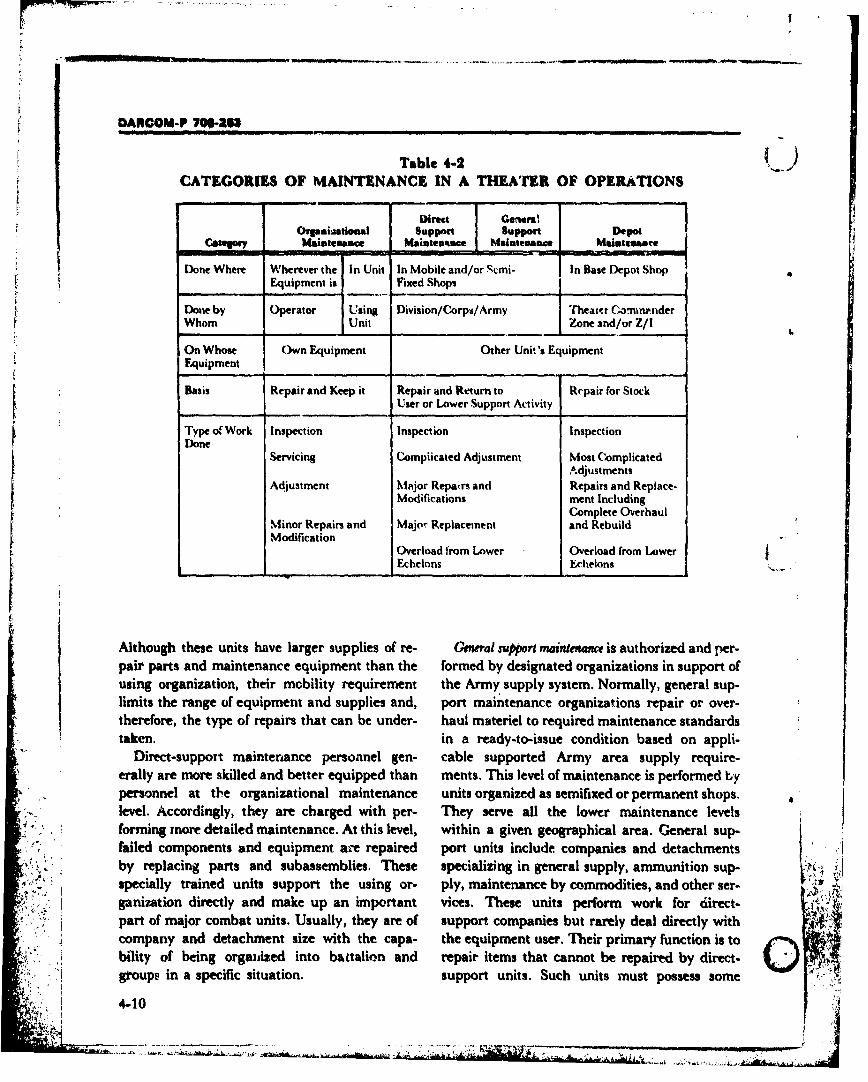
DARCOM-P 700-231
Table 4-2 )CATEGORIES OF MAINTENANCE IN A THEATER OF OPERATIONS
Dime~ GerwrilOrpaoiaatonal Support support Depot
maimeembace - Iateaace alatenaamc Mmantiebacte
Done Where Wherever the In Unit In Mobile and/or Scmi- In Base Depot Shop
Equipment is Fixed Shops
Done by Operator Using Division/Corps/Arrny Theat.cr ComninerderWhom Unit Zone and/or Z/1
On Whose Own Equipment Other Unit's EquipmentEquipment
Basis Repair and Keep it Repair and Return to Repair for StockUser or Lower Support Activity
Type o( Work Inspection Inspection InspectionDone
Servicing Compiicated Adjustment Most ComplicatedAdjustments
Adjustment Mai'jor Repairs and Repairs and Replace.Modifications ment Including
Complete Overhaul,Minor Repairs and Major Replacement and RebuildModification
Overload from Lower Overload from Lower
Echelons E~chelons
Although these units have larger supplies of re- GaerraI support maintemtmc is authorized and per-pair parts and maintenance equipment than the formed by designated organizations in support ofusing organization, their mobility requirement the Army supply system. Normally, general sup-limits the range of equipment and supplies and, port maintenance organizations repair or over-therefore, the type of repairs that can be under- haul matteriel to required maintenance standardstaken. in a ready-to-issue condition based on appli-
Direct-support mainten~ance personnel gen- cable supported Army area supply require-erally are more skilled and better equipped than ments. This level of maintenance is performed b~ypersonnel at the organizational maintenance units organized as semifixed or permanent shops.level. Accordingly, they are charged with per- They serve all the lower maintenance levelsforming more detailed -maintenance. At this level, within a given geographical area. General sup-
failed components and equipment are repaired port units include companies and detachments
specially trained units support the using or- ply, maintenance by commodities, and other ser-ganization directly and make up an important vices. These units perform work for direct-part of major combat units. Usually, they are of support companies but rarely deal directly with 4'4company and detachment size with the capa- the equipment user. Their primary function is tobility of being organizied into battalion and repair items that cannot be repaired by direct- Igroups in a specific situation. support units. Such units must possess some
4-10
OARCOM-P 70•. .53
mobility io that they can remain within con- firiag mechanism, obturator, and other parts re-venient, aorkinp distance of the direct-support quiring disassembly for cleaning. Field strippingunits Liut rapid movement is not itaperative. considerations; foolproof issembly qualities ofSome mobility is sacrificed so that they can have. designs.
adequate time and facilities to perform their mis- 3. Evaluate simplicity of tasks - time ex-sion. A high degree of specialization and com- pended, cxtent of special tools needed, and de-petence can be expected at this level. Personnel gree of personnel skills required.usually are trained extensively, to become ex- 4. Evaluate degree of ease, or difficulty, en-perts in specific components, countered in extreme climate maintenance of the
L•pol madr"ncnce, or thorough overhaul of breech system.economically repairable materiel, augments the 5. Evaluate measures to prokcct the systemprocurement program. Depot maintenance or- from the environment (e.g., control of dirt andgani-ations are nonmobile with equipment of ex- mud catching features in mechanisms and equip-treme bulk and complexity. The high volume ment; provision of covers for adverse weather).
r operation possible in these shops lends itself to ef- 6. Evaluate safety design features.fective use of assembly line techniques. This, in 7. Inspect critical dimensions, threads, fillets,tu-n, permits the use of relatively unskilled etc.; con..uct diagnostic inspections usingworkers in most positions, with a concentration magnaflux, ultrasonics, and X-ray.of highly skilled specialists in key positions.Depot maintenance shops are located in areas re- 4-5.2 DURABILITYmote from the theaters of operation and may per- Durability is a special case of reliability (MILform services for several theaters. Operation of STD-721). Durability is the probability that anthese installations by troops is not necessary; the item will successfully survive its projected life,bulk of the work may be done by the local labor overhaul point, or rebuild point (whichever is themarket under military supervisiong more appropriate durability measure for the
Maintenance activities relating to or part of item) without a fail urAbil ability failure isdevelopment programs must be examined during considered to be a malfunction that precludesin-process reviews (Ref. 9). This constitutes a re- further operation of the item and is great enoughview of a materiel development project con- in cost, safety, or time to retore, that the itemducted at critical points of the development cycle must be replaced or rebuilt. Thus durability im-to evaluate project status, effect coordination, plicitly describes the ability of a system to with-and facilitate proper and timely decisions to as- stand the rugged environment of field use, roughsure ultimate acceptability for use by the Army. handling, and lack of or improper maintenance.In-process reviews offer the various activities or Durability of a system, i.e., its ability to with-agencies involved in the project the opportunity stand abuse without failing or becoming inef-to analyze the subsystem from their respective ficient, is a major component of reliability andviewpoints. Trade-offs can be evaluated and also of availability. In breech mechanisms, re-problem areas investigated. The following check- dundancy plays an important role in durability.list indicates the major maintainability related If the automatic breech activation system fails, aareas that are considered during in-process re- backup manual mode of operation is available toviews: keep the weapon firing. Evaluation of tests re-
1. Evaluate access features of maintenance sults from service life and accelerated testing,. . tasks-lubrication points; surfaces to be cleaned along with input from in-process reviews, help
and oiled. pinpoint shortcomings in durability factors (e.g.,2. Evaluate assembly-disassembly tasks (in- fatigue, wear, corrosion, and deterioration of
cluding field adjustment needs) - applicable to finishes and paints). However, the major input
4-11
• . i• ,.. - - - - ._ .. . ... . .. . . .
DAfOOM-P 7W6•-
for determining system durability comes from ac- ticipated field failures and other rcasons. Un-
i tual fiel use. As mentioned in par. 4-5, con- fortunately, there seems to be no foolprooftinuous redesign of a weapon system usupily con- method of simulating or testing all the situationstinues throughout it% useful Ife because of unan- that a system will undergo in actual combat use.
SECTION II. DESIGN FINALIZATION
4-6 INCORPORATION OF duction engineering. It is the basis of Govern.DEVELOPMENT&L RESULTS ment acceptance or rejection.
During the developmental testing stages, nu- 4-7.1 PRODUCT SPECIFICATIONmerous deficiencies will be discovered that will.necessitate design changes, improvements, ad- The product specification, the basic docu-ment of the TDP, contains general design cri-ditions, deletions, and reevaluations. In this sec-tion methodology to ensure the orderly trans- teria. performance requisites, and inspection pro-ition from test prototype to production weapon cedures not covered by the engineering draw-will be described. ings.
4-7.2 DATA LIST4-7 ORGANIZATIONAL The data list is an inventory of the total con-
DOCUMENTATION, THE tent of the TDP (including those items in-TECHNICAL DATA PACKAGE corporated by reference) and a record of revision
To ensure an orderly development process, the status. All specifications and standards (military,designer must maintain progress documenta- federal, and industrial) and all standard hard-tion. Such documentation includes maintaining ware items are identified.up-to-date specifications, data files, log books,design review and progress reports, and detail 4-7.3 PARTS LISTand assembly drawings. The final output of de- The parts list is indentured starting at the topvelopment phase documentation is the technical part (the complete system) and gives the totaldata package (TDP). The TDP, which normally physical content of the end item. A separate parts U
is developed over a period of approximately 18 list is prepared for each assembly which does notmonths, becomes the vehicle by which the Army contain a list of material on the drawing de-conveys requirements to the manufacturer. The picting it. A list of material appears in the draw-"TDP documentation contains all design dis- ing only when the item is an inseparable as-
closure data, specifications. quality assurance sembly or a detailed drawing. The parts list is as-provisions, and acceptance criteria required for sociated with its assembly drawing by use of thedevelopment, production, and acceptance of the same number. Because assembly drawings lackitem. It includes the data lists, parts lists, draw- definitive specifications, item quantities, andings, Government standards and specifications, connecting hardware information, the parts listindustry standards and specifications, and end serves to complete the data in a manageable anditem final inspection requirements. The TDP convenient form.1provides the Government with an equitable basisfor competitive bidding and industry with the of- 4-7.4 DRAWINGSficial documentation needed for bidding, maL,.. Drawings are the heart of the TDP since they ;.\or-buy decisions, estimating, vendor item pur- alone can control and completely delineate Jchasing, speciality house procurement, and pro- shape, form, fit, function, and interchangeability
4-12
S..... • "- ..... :-'.................................................................................................... ' ... .
!T
* I
DARCOM-P 706-263
requirements for full competitive procurement. supply his own gages and inspection equipmentMilitary design drawings are prepared in ac- to meet specified detail or general requirements.cordance with Ref. 10. All or part of the TDP re-ceived by the industrial user, bidder, or manu- 4-7.6 STANDARDS AND
facturer nay be in the form of 35 mm microfilm SPECIFICATIONSaperture cards (Ref. 11). This format reduces the Government standards and specifications in-storage and shipping bulk of the TDP (or por- clude the pertinent Military Standards, Militarytion thereof) by about 95%. The use of aperture Specifications, Federal Standards and Specifi-ca;ds enables the user to reproduce as many cations, and applicable Government handbookscopies as he may require. and documents. Appropriate indust:'y standards
TDP drawings are engineering rather than and specifications, as well as those published byproduction drawings. DOD Instruction 5010.12 societies, associations, or committees are ir.states that "End product documentation is de- c'luded in the TDP.
fined as a design disclosure package which is suf-ficient to permit a competent manufacturer to re- 4-7.7 END ITEM FINAL INSPECTION
produce an item without recourse to the original REQUIREMENTS (EIFIR)
design activity". An engineering drawing ap- This section of the TDP is a controlling factorplicable to a part -. when supplemented by the in the final Government acceptance of an endreferenced specifications and standards - item. The EIFIR specifies a record requirementshould include all dimensions, tolerances, notes, and a chronological sequence listing relative toand other data necessary to describe fully the quality characteristics which must be verified forcharacteristics of the part after all manufac. functional performance and completeness by theturing has been completed. producei. Defects and the resultant corrective ac-
tions are listed to establish a permanent record ofthe final inspection of the item. The EIFIR is
S4-7.3 QUALITY ASSURANCE DATA used in conjunction with the quality assuranceThe quality assurance data included in the provisions section of the specification, the SQAP,
,'TDP consists of the supplementary quality as- and any special contract requirements affectingSsurance provisions (SQAP), the inspection quality characteristics.
equipment drawings, and the appropriatequality assurance pamphlets. The SQAP cannot 4-7.8 REVISION SYSTEMcontain elements not cross-referenced to the ap- If the need for TDP revision develops, it is im-
plicable design requirements on the parent docu- perative that care be exercised in so doing. Forment. The SQAP is an inspection instrument example, changes made to any drawing that af-providing quality assurance check points. fects the interchangeability of repair parts for an
Certain end items requiring closely toleranced equipment in the supply system must reflect aand geometrically controlled machine surfaces change in the affected part number. All revisionsare accepted by the Government inspectors after made to drawings and parts lists necessitatescrutiny in conjunction with use of a Govern- follow-through revisions up-dating all drawingsment supplied gage, an item normally not corn- lists in which the revised drawing and parcs listsmercially available. Since it is supplied to the are mentioned.producer, certain limitations and restrictions areenforced. For each Government gage, there is an 4-8 OPERATING AND
associated quality assurance pamphlet detailing MAINThNANCE MANUALSits operation and maintenance. More often, how- In addition to the TDP, it is normally neces-ever, the production contractor is expected to sary to prepare operating and maintenance
4-13
" "•-. • ,: •.. / .... ...... .. .. ... . ,: ; . . ... . ...
DARCOM-P 70-6253
manuals. These documents must be written to One caution is in order concerning standardi-allow personnel with a minimum of technical zation. Items which are or have been standardtraining to operate and repair the equipment will not necessarily remain standard for the life of'with a minimum of supervision or special train- the breech mechanism design being undertaken.ing. For complex systems, several maintenance In order to assure that any specified standardmanuals - one for each level of maintenance parts will be available when needed, the usingactivity - are usually necessary. Operating and agency should have a controlling voice in anymaintenance information on breech mecha- future revision or obsolescence action taken bynisms normally is included ir a larger manual the supplier.covering the entire weapon. Interchangeability is defined as the capacity of4-9 STANDARDIZATION AND any given part, unit, or material to be substi-
INTERCHANGEABILITY tuted for a like part, unit, or material. There areStandardization as a practice refers to the es- two basic types of interchangeability: (1)
tablishment of engineering procedures targeted functional, in which the two items fulfill the sameto achieve the greatest practical uniformity of requirements for the operation of the largerdesign. As this practice applies to breech systems, and (2) physical, which exists if the twomechanism design, it essentially is the assess- items can be mounted or connected in the samement of procedures, specifications, configura- configuration, but the proper functioning of thetions (as in thread profiles), standard compo- device cannot be restored. From an expediencynents, and tools in lignt of their records of prior viewpoint, as with repair under field conditions,successful achievement in use. functional interchangeability is an obviously
One signifi'znt advantage which can be preferable alternative and should be the objectivegained through this practice of assessing stan- of the design team wherever practical.dard items for possible use, is the existence of In units requiring frequent servicing and re-supporting production testing and gages as well placement of component parts because of wear oras maintenance tools. By using standard items, it damage, every part should be ,ompletely inter-is possible to eliminate the time and expense changeable with every similar part in every unit.which would be incurred through implementing In units expected to function satisfactorily with-a new design. Further, there will exist test results out replacement of parts, it may be uneconomi-which can serve as additional input into the de- cal to insist that parts be strictly interchange-cision process. able. The parent unit itself should be inter-
It should be emphasized that standardization changeable with all other similar units, but theshould be given no higher priority in the design parts of one parent unit need not be inter-process than any other of the goals established changeable with those of another.initially. Since the uitimate test for acceptance of Within the context of the breech mechanisma design will be a vigorous firing test, the data design, interchangeability becomes fundament-available through standardization should be con- ally a consideration of the fit and alignment be-sidered as informational only. tween mating parts. Proper fit and alignment are
Further, standardization should not be achieved through either of two processes: (1)allowed to inhibit design improvement efforts. prior design and control of all critical features ofThe advantages and disadvantages of innovation all mating parts, or (2) a finish machining of theshould be compared on an equal basis with those mating parts at assembly to some final dimen-of standardization when deciding which sion. For purposes of comparison of these two ap-philoscphy will be incorporated into the final de- proaches, consider the case in which a cam fol- . "sign effort, lower lever is to be mounted in a specified axial
4-14
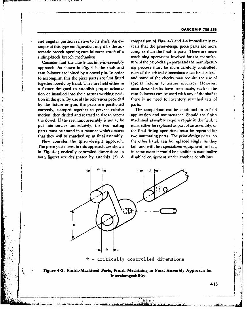
DARCOM-P 706-253
and angular position relative to its shaft. An ex- comparison of Figs. 4-3 and 4-4 immediately re-ample of this type configuration might bo the au- veals that the prior-design piece parts are moretomatic breech opening cam follower crack of a complex than the final-fit parts. There are moresliding-block breech mechanism. machining operations involved for the manufac-
Consider first the finish-machine-in-assembly ture of the prior-design parts and the manufactur-approach. As shown in Fig. 4-3, the shaft and ing process must be more carefully controlled;cam follower are joined by a dowel pin. In order each of the critical dimensions must be checked,to accomplish this the piece parts are first fitted and some of the checks may require the use of
together loosely by hand. They are held either in special fixtures to assure accuracy. However.a fixture designed to establish proper orienta- once these checks have been made, each of thetion or installed into their actual working posi- cam followers can be used with any of the shafts;tion in the gun. By use of the references provided there is no need to inventory matched sets ofby the fixture or gun, the parts are positioned parts.correctly, clamped together to prevent relative The comparison can be continued on to fieldmotion, then drilled and reamed to size to accept application and maintenance. Should the finishthe dowel. If the resultant assembly is not to be machined assembly require repair in the field, itput into service immediately, the two mating must either be replaced as part of an assembly, orparts must be stored in a manner which assures the final fitting operations must be repeated forthat they will be matched up at final assembly. two nonmating parts. The prior-design parts, on
Now consider the (prior-design) approach. the other hand, can be replaced singly, as theyThe piece parts used in this approach are shown fail, and with less specialized equipment; in fact,in Fig. 4-4; critically controlled dimensions in in some cases it would be possible to cannibalizeboth figures are designated by asterisks (*). A disabled equipment under combat conditions.
* = critically controlled dimensions
Figure 4-3. Finish-Machined Parts, Finish Machining in Final Assembly Approach forInterchangeability
4-15
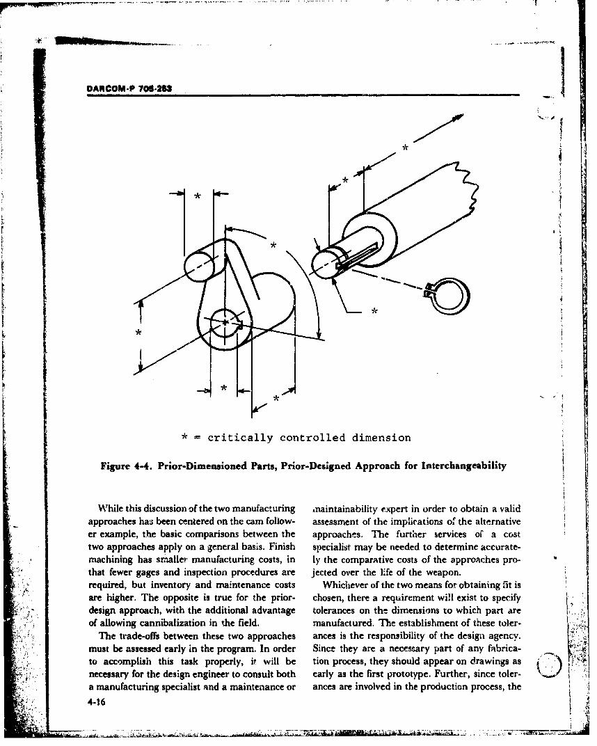
DARCOM-P 706-253
*critically controlled dimension
Figure 4-4. Prior-Dimensioned Parts, Prior-Designed Approach for Interchangeability
While this discussion of the two manufacturing mnaintainability expert in order to obtain a validapproaches has been centered on the cam follow- assessment of the implications of the alternativeer example, the basic comparisons between the approachts. The further services of *a costtwo approaches apply on a general basis. Finish specialist may be needed to determine accurate-machining has smaller manufacturing costs, in ly the comparative costs of the approaches pro-that fewer gages and inspection procedures are jected over the life of the weapon.required, but inventory and maintenance costs Whichever of the two means for obtaining Cit isare higher. The opposite is true for the prior- chosen, there a requirement will exist to specifydesign approach, with the additional advantage tolerances on the dimensions to which part areof allowing cannibalization in the field, manufactured. The establishment of these toler-
The trade-offs between these two approaches ances is the responsiibility of the design agency.must be assessed early in the program. In order Since they are a necessary part of any fabrica-to accomplish this task properly, it will be tion process, they should appear on drawings asnecessary for the design engineer to consult both early as the first prototype. Further, since toler-a manufacturing specialist and a maintenance or ances are involved in the production process, the
4-16
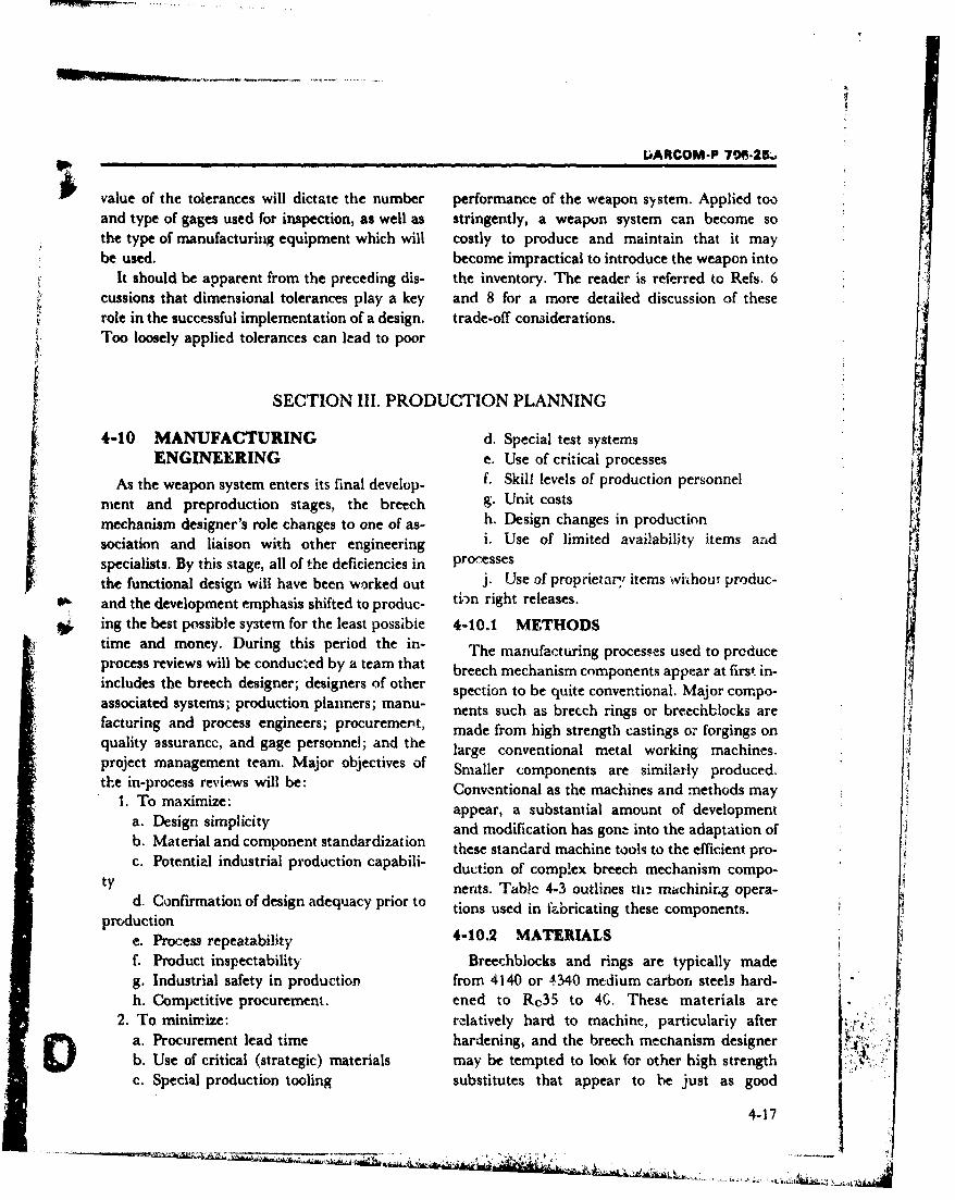
LARCOM-P 7.-2M,
value of the tolerances will dictate the number performance of the weapon system. Applied tooand type of gages used for inspection, as well as stringently, a weapon system can become sothe type of manufacturing equipment which will costly to produce and maintain that it maybe used. become impractical to introduce the weapon into
It should be apparent from the preceding dis- the inventory. The reader is referred to Refs. 6cussions that dimensional tolerances play a key and 8 for a more detailed discussion of theserole in the successful implementation of a design. trade-off considerations.Too loosely applied tolerances can lead to poor
SECTION 11. PRODUCTION PLANNING
4-10 MANUFACTURING d. Special test systemsENGINEERING e. Use of critical processes
As the weapon system enters its final develop- f. Skill levels of production personnel
ment and preproduction stages, the breech g. Unit costs
mechanism designer's role changes to one of as- h. Design changes in production
sociation and liaison with other engineering i. Use of limited availability items ard
specialists. By this stage, all of the deficiencies in processes
the functional design will have been worked out j. Use of proprietary items wi'hout produc-S and the development emphasis shifted to produc- ti.n right releases.
S ing the best possible system for the least possibie 4-10.1 METHODStime and money. During this period the in- The manufcturing processes used to produceprocess reviews will be conducted by a team that breech mechanism components appear at first in-includes the breech designer; designers of other spection to be quite conventional. Major corpo-associated systems; production planners; manu- nents such as breech rings or breechb~locks arefacturing and process engineers; procurement, made from high strength castings or forgings on
quality assurancc, and gage personnel; and the large conventional metal working machines.project management team. Major objectives of Smaller components are similarly produced.the in-process reviews will be: Conventional as the machines and methods may
1. To maximize: appear, a substantial amount of developmenta. Design simplicity and modification has gone into the adaptation of-b. Material and component standardization these standard machine tools to the efficient pro-c. Potential industrial production capabili- duction of comp!ex breech mechanism compo-
ty nents. Table 4-3 outlines tli-. machining opera-d. Confirmation of design adequacy prior to tions used in ortinese cm pents
tions used in fabricating these components.production
e. Process repeatability 4-10.2 MATERIALS
f. Product inspectability Breechblocks and rings are typically madeg. Industrial safety in production from 4140 or 4340 medium carborn steels hard-h. Competitive procurement. ened to Rc35 to 4G. These materials are
2. To mininrize: relatively hard to machine, particulariy aftera. Procurement lead time hardening, and the breech mechanism designerb. Use of critical (strategic) materials may be tempted to look for other high strengthc. Special production tooling substitutes that appear to be just as good
4-17
.................... ............ ":•.t..'. •... " -
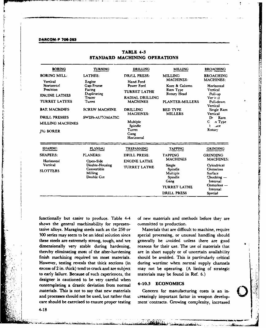
DARCOM-P 706-263
TABLE 4-3STANDARD MACHINING OPERATIONS
iv
BORING TURNING DRILLING MILLING BROACHI-NG
BORING MILL: LATHES: DRILL PRESS: MILLING BROACHINGHand Feed MACHINES: MACHINES:
Horizontal Gap-Frane Power Feed Knee & Column HorizontalPrecision Facing TURRET LATHE Ram Type Vertical
ENGINE LATHES Duplicating Rotary Head Pull-upTracer RADIAL DRILLING Ver iral
TURRET LATHES Turret MACHINES PLANTER-MILLERS Pull-downVertical
BAR MACHINES SCREW MACHINE DRILLING BED TYPE Single RamMACHINES: MILLERS Vertical
DRILL PRESSES SWISS-AUTOMATIC Dr " RamMILLING MACHINES Multiple C .n TypeSpindle
: ace
JIG BORER Turret RotaryGangHorizontal
SHAPING PLtkNING TREPANNING TAPPING GRINDING
SHAPERS: PLANERS: DRILL PRESS: rAPPING GRINDING
Horizontal Open-Side ENGINE LATHE MACHINES MACHINES:Vertical Double-Housing TURRET LATHE Single Cylindrical
SLOT71ERS Convertible Spindle CenterlessMilling Multiple Surface
Double Cut Spindle Chucking -Gang Internal
TURRET LATHE Centerless -Internal
DRILL PRESS Special
functionally but easier to produce. Table 4-4 of new materials and methods before they areshows the general machinability for represen- committed to production.tative alloys. Maraging steels such as the 250 or Materials that are difficult to machine, require300 series may seem to be an ideal solution since special processing, or unusual handling shouldthese steels are extremely strong, tough, and are generally be avoided unless there are gooddimensionally very stable during hardening, reasons for their use. The use of materials thatthereby eliminating most of the after-hardening are in short supply or of uncertain availabilityfinish machining required 'on most materials, should be avoided. This is particularly criticalHowever, testing reveals that thick sections (in during wartime when normal supply channelsexcess of 2 in. thick) tend to crack and are subject may not be operating. (A listing of strategicto early failure. Because of such experiences, the materials may be found in Ref. 6.)designer is cautioned to be very careful when
- I contemplating a drastic deviation from normal 4-10.3 ECONOMICS
materials. This is not to say that new materials Concern for manufacturing costs is an in- )~and processes should not be used, but rather that creasingly important factor in weapon develop-care should be exercised to ensure proper testing ment contracts. Growing complexity, increased
4-18
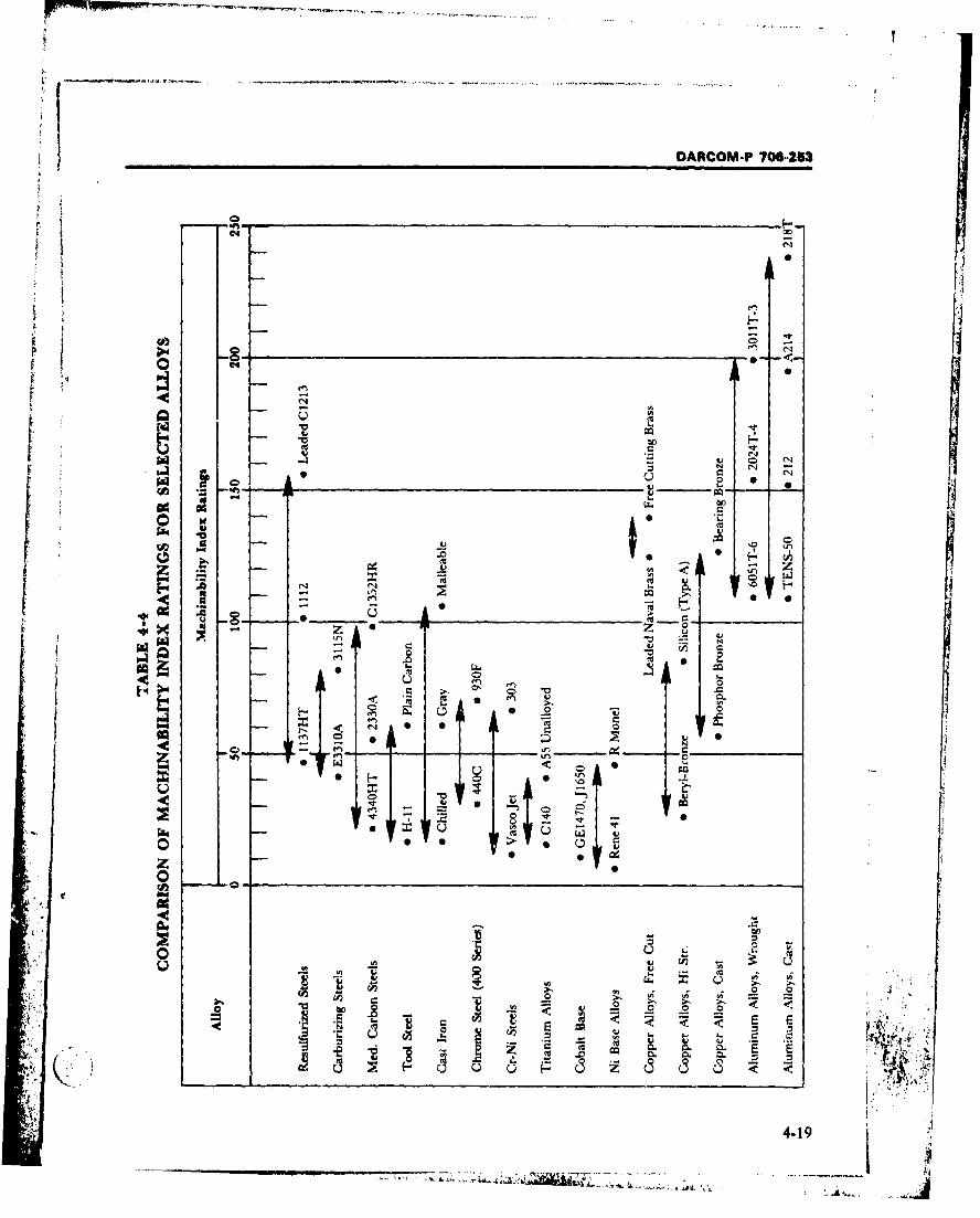
DARCOM.P 706-253
C1 4 .
1~t4 10..
U C.
o fnN -1
14 ~140to)o
41
-4 1
DANCOM-P 706-213
performance requirements, and a general rise in reviews the costs associated with producing a 2
production costs have greatly increased the costs typical piece part. Each of these costs is a func-of procuring weapons. Electrically operated tion either directly or indirectly of the basicbreech mechanisms such as the 152 mm gun design of the part, the material used, thelauncher, for example, cost far more to produce tolerances and finishes specified, and the gagingthan a more conventional breech and require required.close scrutiny to optimize production processes An additional significant cost considerationand minimize costs. The economics of producing that is often overlooked is the volume to beany weapon component or system is a complex produced. A design that is optimal for prototypematter composed of numerous cost factors. It is production is usually far from optimal for small-the responsibility of the designer not only to volume production and is most surely very un-design a workable breech mechanism but to economical to mass produce. The design of theminimize the cost of producing it. Fig. 4-5 part, the material used, the machining and
Total Cost per Piece
Machining Cost
'.4-AP.,
U Total RegrindingCost
Nonproductive
•: ''' "I': 2 "" '''" "Tool CotChanging
0 200 400 600 800 1000 1200 1400
Cutting Speed, fpm
Figure 4-5. Total Cost per Piece-Sum of Tool Cost, Machining Cost, andNonproductive Cost
4.20
-----------------------------------------
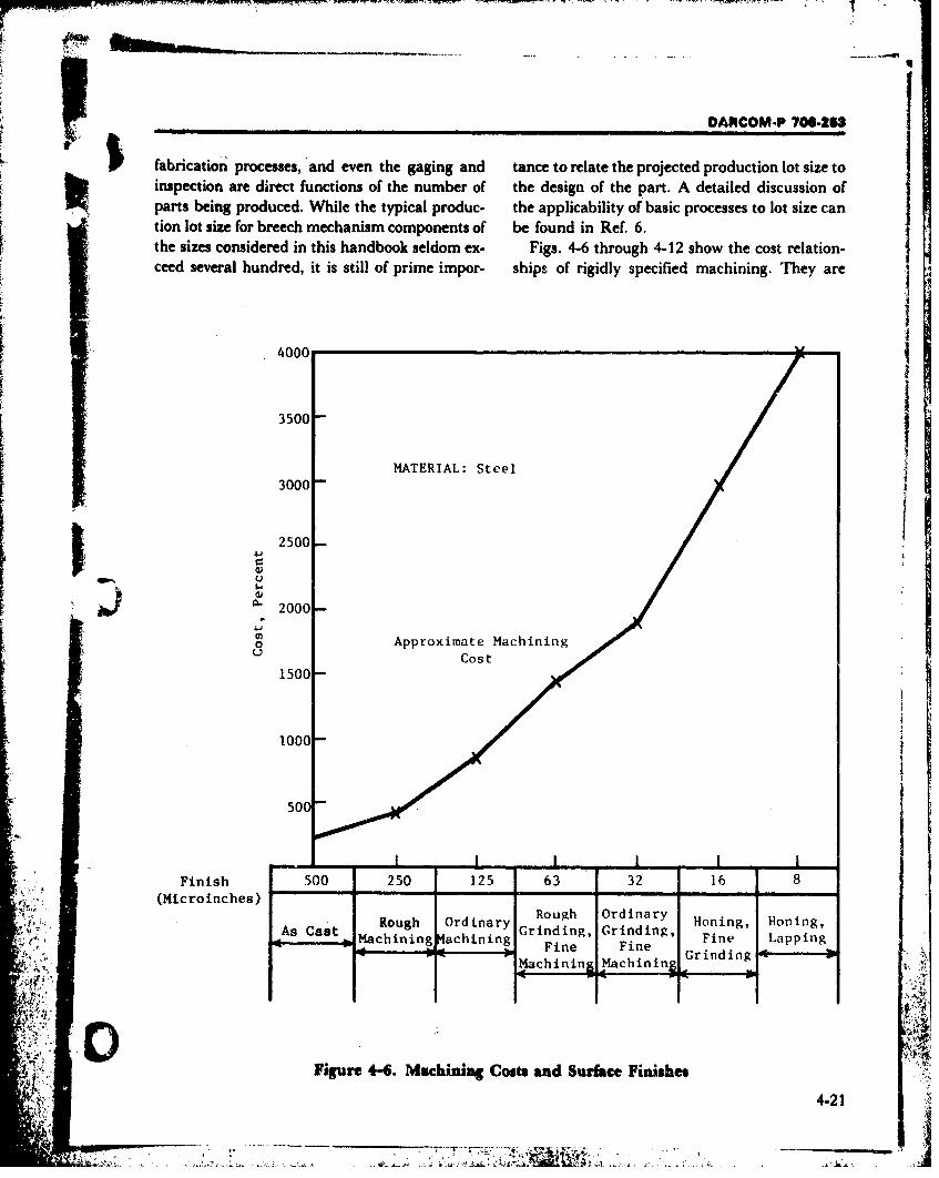
DANCOM-P 706-23
fabrication processes, and even the gaging and tance to relate the projected production lot size toinspection are direct functions of the number of the design of the part. A detailed discussion ofparts being produced. While the typical produc- the apiaiiyo ai rcse oltsz ation lot siefor breech mechanism components of be appldicailt oef. bai6 rcesst.otsza
thesizs cnsiere i ths hndbok eldm x- Figs. 4-6 through 4-12 show the cost relation-ceed several hundred, it is still of prime impor- ships of rigidly specified machining. They are ~ 5
4000
3500 IMATERIAL: Steel
3000
2500
0 Approximate Machining
Cost
1Q000
500
Finish 502015 6 21(Hicroinches)
-AB Cast- Roug Odnry Grinding, Grinding, Fie LappingMachining Machining Fine Fine Fn
A Figure 4-6. Machining Costs and Surface Finishes
4.21
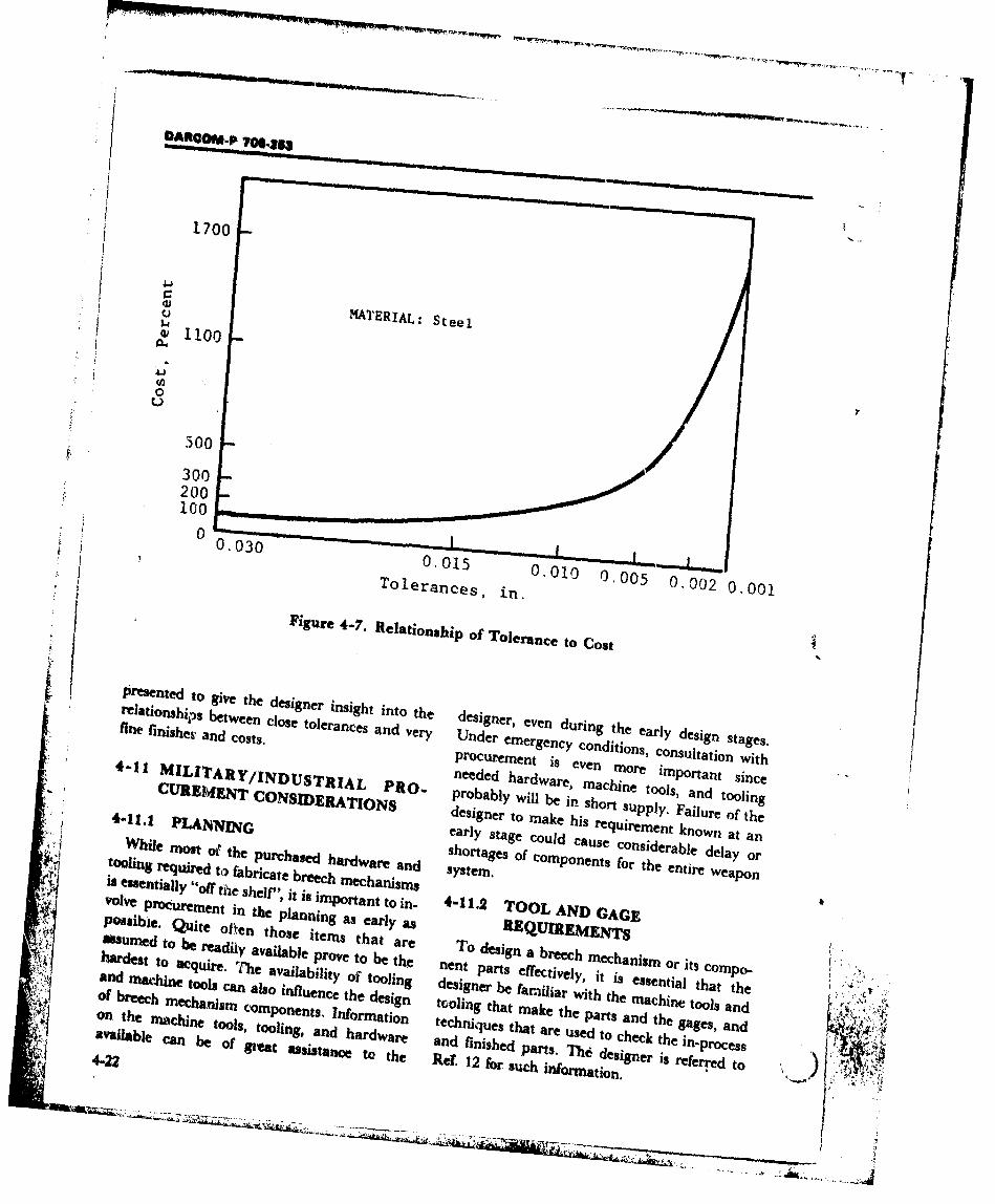
1700
/ MATERIAL: Steel1100
0
500
.300
200
t) 0. 15 0. i~ ~0 .002 0.001Tolerances, 0-1n0.0
Figure 4-7. Relationship of Tolerauce to Cost
Presented to give the designer insight into the designer, even during the early design stages.fine finishev ab end closts
Soeacsadvr ne
oslaionwit4-1MILE rARY/1NDUSTRA needed hardware, machine tools, and tooling
CURE1J~ ONSDEI~IONPRO. probably will be in short supply. Failure of the
d e si n e r t o a k e h is r e q u ir e m e n t k n o w n a t a n
4-11.1 PLANNING early stage could cause considerable delay orshortages of components for the entire weapon
t hln we d mot ofabicth e burchased chardwreanWhlilgeuie ot o farcth e purchag m hardaead sse18 essentially "Off the shelf", it is important to in- 4-11.2 TOOL AND) GAGE"V"'~eprocuremient in the planning as early as R.EQUIREMENTSpossibie. Quite often those items that are To design a breech mechanism or its cornpo.
assumed to be readilY available prove to be the nent parts effectively, it is essential that the
hardest to acquire. The availability of tooling designer be familiar with the machine tools and
Sl and machine tools can also influence the design tooling that mk h partsadtege, a n
of breech mechanijsm comnponents, Information techniques that are used to check the in-processjOn the maichine tools, tooling, and hardware and finished pat.TAdsgerileerdtq 4-22
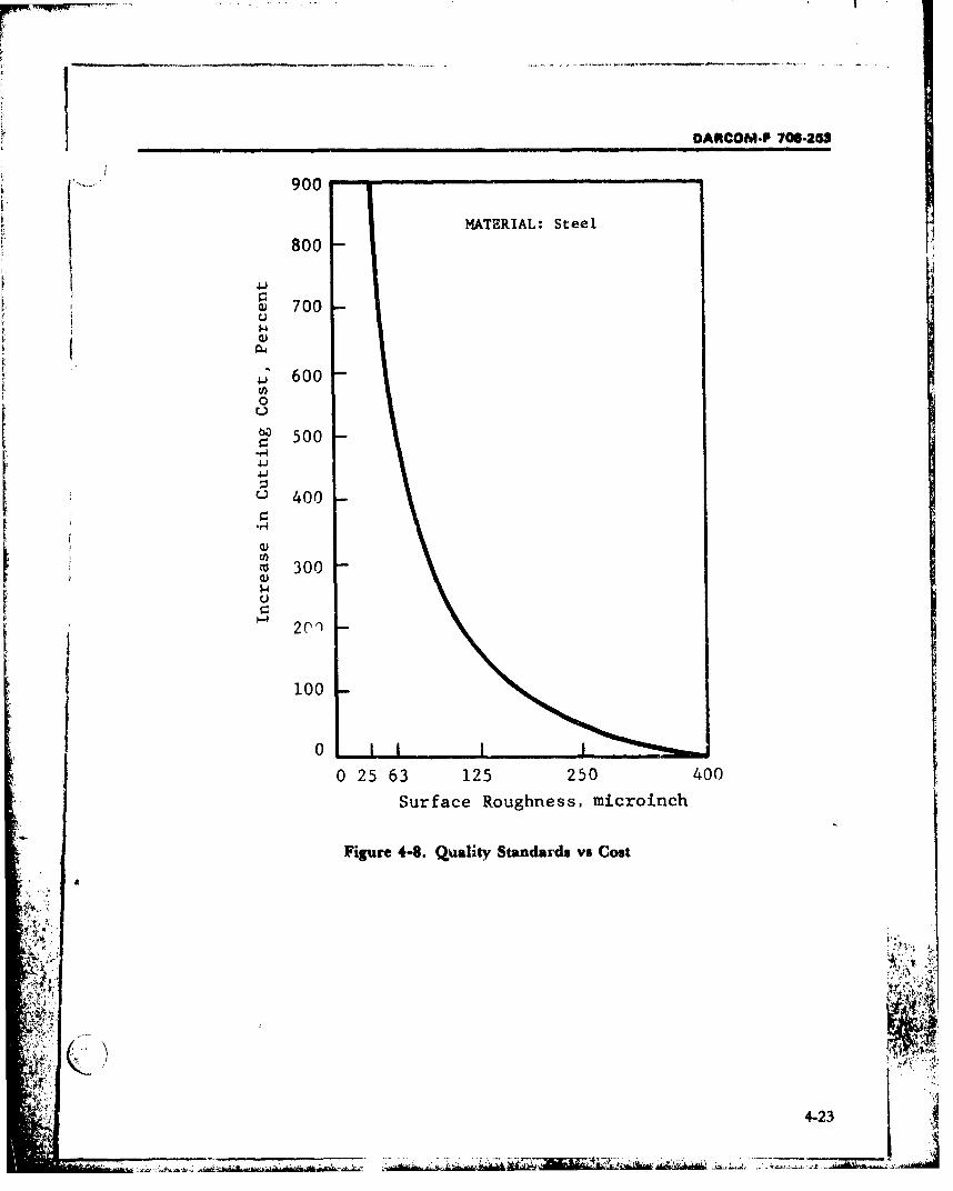
DARCOM-P 706-283
900
MATERIAL: Steel
800
Q 700U'.4
S6000
S500*1-4
400
CD)Ico 300U
0r
0 25 63 125 250 400
Surface Roughness, microinch
Figure 4-8. Quality Standards vs Cost
4
t' 'I•
SF• t•
! y ,2
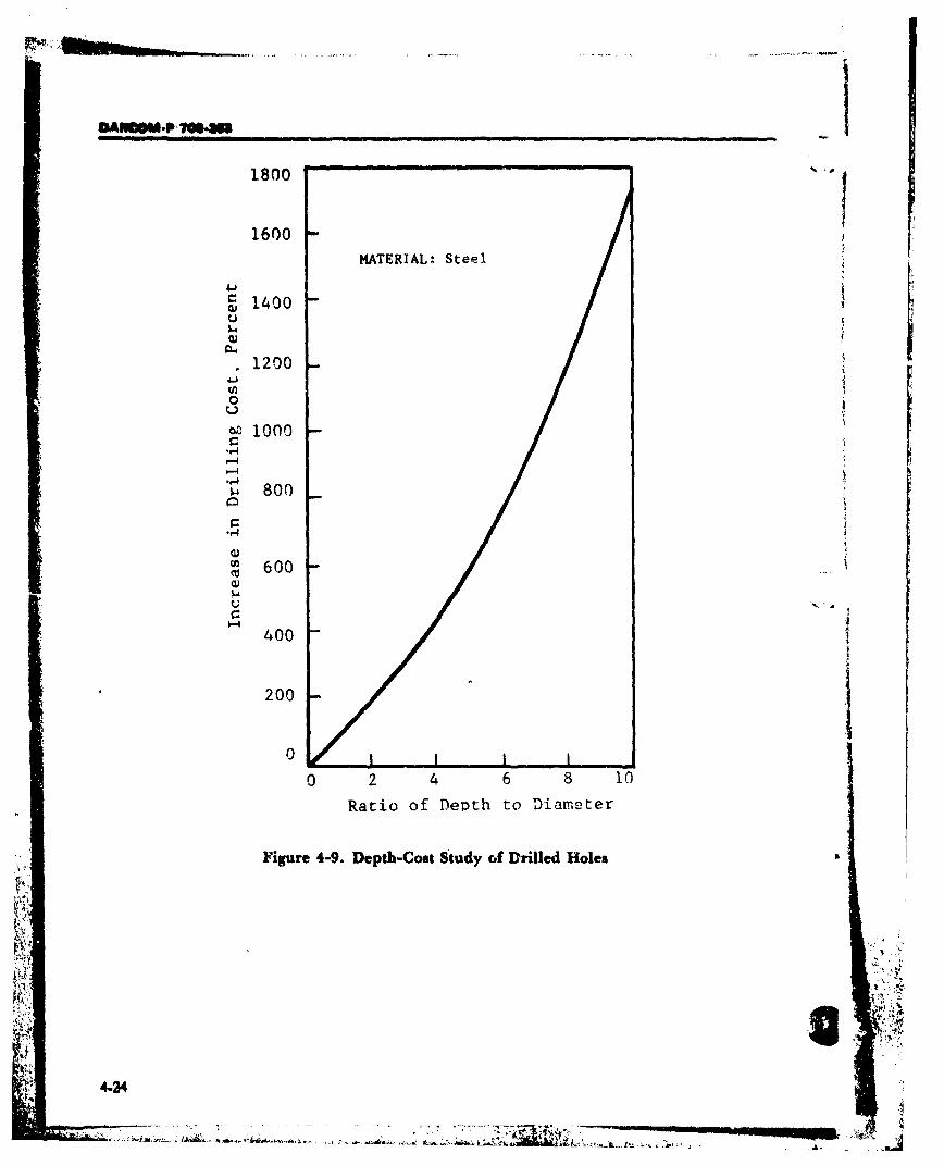
OASM4 _@SU -
1800
1600
MATERIAL: Steel
1400I-U
1200 i i°-i
w 1000
.-,4
i- 800
600
400
200
0
0 2 4 6 8 10
Ratio of Depth to Diameter
Figure 4-9. Depth-Cost Study of Drilled Holes
4-24
-. . .... , ,.. ..
~ ~L. *~ ~ - '~ A4. I
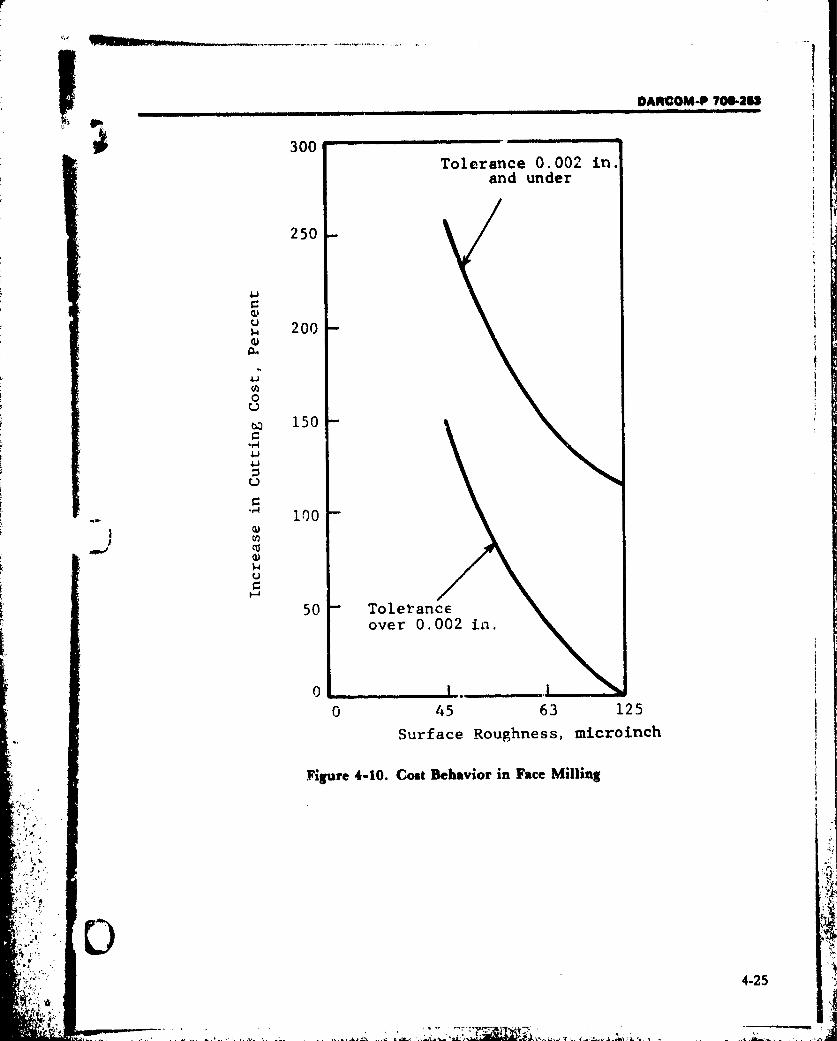
DARCOM-P 706-2.
300 ..Tolerance 0.002 in.
and under
250
UU 200
0
w 150*r'
C,-4
"*• 100
(U
50 Toleranceover 0.002 in.
0 45 63 125
Surface Roughness, microinch
"Figure 4-10. Cost Behavior in Face Milling
42
.. ,•** :.4-25
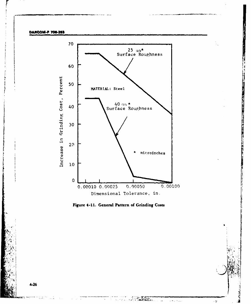
DAOCOM.P 70646
70
0 Surface Roughness
60
0i(D 50•
• 5oI' MATERIAL: Steel
o 40U Surface Roughness
30
Q) 2
*microinches
ý-r 10
0
0.00010 0.00025 0.00050 0.00100
Dimensional Tolerance, in.
Figure 4-11. General Pattern of Grinding CostsiI- ---C
• +-1 4-t6.+
4.6
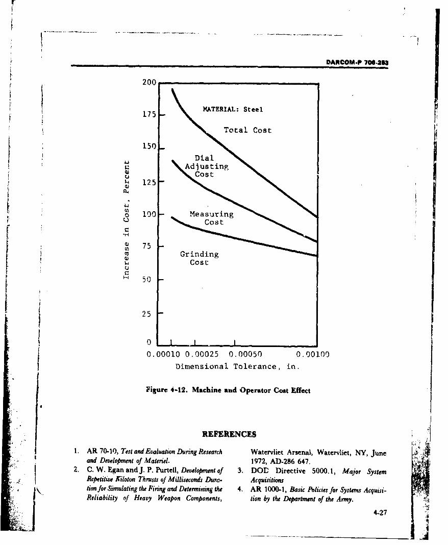
F_
DARCOM.P 706-263
200
175 MATERIAL: Steel• ~175-
Total Cost• . 150
• _ Dial15 0Adjusting
• 125
o 100- Measuring
°os
Q) 75S~Grinding
ý- Cost
S' 50
25
0rS0 1 1 1t
0.00010 0.00025 0.00050 0.00100
Dimensional Tolerance, in.
Figure 4-12. Machine and Operator Cost Effect
REFERENCES
1. AR 70-10, Test and Evaluation During Research Watervliet Arsenal, Watervliet, NY, Juneand Development of Materiel. 1972, AD-286 647.
2. C. W. Egan and J. P. Purtell, Development of 3. DOD Directive 5000.1, Major SystemRepetitive Kiloton Thrusts of Milliseconds Dura- Acquisitionstion for Simulating the Firing and Determining the 4. AR 1000-1, Basic Policies for Systems Acquisi-Reliability of Heavy Weapon Components, tion by the Department of the Army.
4-27

DARNCOM P 7064M
IRENC&3CS (cont'd)5. Letter of Instruction for Implementing the 9. AR 70.1, Army. feerch, Development, and
New Material Acquisition Guidelines, Acquisition.ACSFOR, 23 August 1972. 10. MIL.D-1000, Drawings, Engineering and
6. AMCP 706-100, Engineering Design Hand- Associated Lists.book, Desop' Guidance foT Producibility. 11. MIL-STD-804, Format and Coding, Tabula-
7. AMCP 702-3, Quality Assurance Reliability tion, and Aperture Cards for EDMS.Handbook. 12. L. E. Doyle, et al., Manufacturing Processes
8. AMCP706-134, Engineering Design Hand- and Materials, Prentice-Hall, Inc.,book, Maintainability Guide for Design. Ernglewood Cliffs, NJ, 1961.
I4
i ,
•' 4.28

DARCOM-P 706-253
GLOSSARY
A ters the projectile and makes it fit tightly in the
accessibility. A measure of the relative ease of bore, thus preventing the escape of gas, and bySadmission to the various areas of an item. engaging the rifling, gives the projectile its spin.
bore diameter. The interior diameter or caliber* angle of tralverse. 1. Horizontal angle through
which a gtn or launcher can be turned on its of a gun or launching tube.mount. 2. Angle between the lines from a gun bore evacuation. Clearing of the bore of pro.or launcher to the right and left limits of the pellant gases and extraneous material after fir-
front that is cuvered by its fire, i.e., the angle ing.through which it is traversed, breech. The rear part of the bore of a gun, espe-
artillery '(arty). Artillery piece. Gun or rocket cially the opening that permits the projectile to
launcher, with mounting, too large or too be inserted at the rear of the bore.heavy to be classed as a small arm. The lower breechblock. The part of a gun, especially a
limit of size or caliber varies somewhat within cannon, which closes the breech. The breech-S .... block usually contains the firing pin, and in
the Armed Services, but the term is presentlyapplied to any gun or launcher which uses am- many types of guns it is also used to chamber
munition of a caliber greater than one inch the round.
and which is not designed for hand or should- breechblock carrier. Hinged member of one
er use. type of breech mechanism which guides and
automatic breech mechanism. A device that supports the rotating breechblock of cannon.
utilizes the energy of recoil, or the pressure of breechblock, eccentric-screw (Nordenfeld).the powder gases, to open the breech, with- This breechblock is cylindrical and is thread-
ecase, icar- ed or its exterior surface to screw into thedraw the fired cartridge cs, insert a new cr
tridge, and close the breech. After firing the breech recess, which is correspondinglyfirst round, the only hand operation necessary threaded. The breecliblock is much larger in
for the firing of succeeding rounds is that of diameter than the bore, and the axis aboutcontinuing to pull the trigger. Present usage of which it rotates does not coincide with the axis
the automatic mechanism is restricted to guns of the bore. There is a U-shaped off-ceterof small caliber that use the small arms car- opening in the block called the loading recess,
tridge, or fire a projectile weighing not more which coincides with , he bore only when thethan a pound. Machine guns have a breech block is in its open pos.tion. The ammunitionSmechanism of the full automatic type. is inserted into the bore through the loading
availability. A measure of the degree to which recess. With ammunition inserted as far as it
an item is in the operable and committable will go., the breechblock is rotated about itsstate at the start of the mission, when the mis- axis approximately a half revolution to close
sion is called for at an unknown (random) the breech and locate the loading recess away
point in time. from the bore. The firing mechanism is madeso that it properly lines up with the bore inclosed position. To open the breech, the block
•B is merely rotated in tihe opposite direction un-
! j band, rotating. A soft metal band around the til the loading recess again comes into align-projectile near its base. The rotating band cen- ment with the bore.
i G-1

DARCOM-P 706-213
GLOSSARY (cont'd)
breechblock, interrupted-screw. Also called breechblock, and greater threaded surface: orslotted-screw. A breechblock consi.;ting es- holding area is possible. This breechblock issentially of a threaded cylindrical block, with used on modern cannon which fire separate-longitudinal sectors of the threads removed, loading ammunition.The breech recess is likewise threaded, with breechblock tray. A tray-like support for thelongitudinal sectors of the threads removed. In breechblock, hinged to the breech of a largeboth cases there are an even number of sec- cannon, which supports the breechblock whentors and the threads are removed- from alter- it is withdrawn and Dermits it to be swungnate sectors. The breechblock is made to move clear of t1he breech.longitudinally into the breech recess without breech bushing. That part of the gun breech onturning, the threaded sector in each instance the interior surfacce of which the threaded andmoving into the blank sector of the mating slotted sectors of the breech recess are formed.part. Then with a comparatively small turn, breech hoop. A ste-!l jacket for reinforcing thethe threads of the breech and block are fully breech end of a built-up cannon. It may con-engaged, and the block is locked. If the threads tain the breech recess which is threaded to re-were not cut out as indicated, several full turns ceive the breechblock.of the block would be required to attain the breeching space. The linear distance betweensame result. the face of the fu'1y closed bolt and the apex of
breechblock operating mechanism. A mecha- the cone formed by a prolongation of thenism which unlocks and withdraws the shoulder taper. This distance, however, isbreechblock from the breech, swings the block sometimes measured from a datum diameter
clear of the breech recess, and then returns it on the first shoulder.
to the firing, or closed, position after loading, breech interlock. Safety device used with wea-There are two types: carrier-supported and pons that are loaded or rammed automatical-
Stray-supported, according to whether sup- ly or in weapons in which the position of the
ported by a breechblock carrier or a breech- breechblock cannot be readily seen by theblock tray. loader. It functions to prevent the loadi'ng or
breechblock, sliding-wedge. A breechblock -amming of a round when the breechblock isthat is rectangular in cross section and slides not ful!v open.in a rectangular recess in the breech ring to breech mechanism. The assembly at the rear ofopen and close the breech. Where the motion a gun which receives the round of ammuni-of the breechblock is vertical, the mechanism tion, inserts it in the chamber, fires the roundis referred to as a vertical sliding-wedge by detonating the primer, and extracts thebreechblock. Where the motion is horizontal, empty case. See also: rutomatic breech mech-the block is called a horizontal-sliding wedge anism.breechblock. breech operating mechanism. A mechanism
breechblock, stepped-thread (Welin). A modi- used for opening and closing the breech. Mayfication of the breechblock, interrupted-screw, be manual, semiautomatic, or automatic inThe breech recess and the breechblock are cut operation. cf: breech mechanism.with a series of stepped threads, so that when breech preponderance. 1. Unbalance of the tip-the breechblock is inserted and turned in the ping parts of a weapon when the weight of thebreech recess, matching sections of stepped "breech end" exerts a greater moment aboutthreads engage. By using the stepped type of the trunnions than does the weight of thethread, less rotation is necessary to close the "muzzle en=d". Modern weapons usually have
G-2

r
DARCOM-P 106-253
GLOSSARY (cont'd)
a muzzle preponderance because of the trun- tube to the muzzle. For example, a 6-in., 50-nions being mounted near the breech end of caliber gun would have a caliber (bore diam-the tipping parts. Unbalance may be cor- eter) of 6 in. and a tube length of 50 calibers orrected by an equilibrator. 2. The amount of 25 ft.the unbalanced moment. cannon. A comflete assembly, consisting of a
breech pressure. In interior ballistics, the pres- tube and a breech mechanism, firing mecha-sure from the propellant gass, acting against nism or base cap, which is 4 component of athe inner face of the breechblock. Because of gun, howitzer, or mortar. It may also includethe movement of the projectile toward the muzzle appendages. "Ihe term i3 generally rim-muzzle, 3 pressure gradient develops, so that ited to calibers greater than one inch.the breech pressure is somewhat greater than case. Short for case, cartridge.I the pressure acting upon the projectile. case, cartridge. An item designed to hold an am-
breech recess. The space at the rear of the bar- munition primer and propellant, and to whichrel assembly of a cannon, formed in the inter- a projectile may be affixed. Its profile and sizeior of the breech ring to receive the breech- conform to that of the chamber of the weaponblock, in which the round is fired except for recoil-
breech reinforce. That pavt of a cannon in front less rifles.of the breech and in the rear of the trunnion chamber. 1. Part of a gun in which the charge isband. placed. In - revclver, it is - hole in the cylin-
breech ring. The breechblock housing, screweL der; in a cannon, it is that space between the•+ or shrunk onto the rear of a cannon, in which obturator or breechblock and the forcing cone.
the breechblock engages. Nominally it is the space occupied by the car-breech tray. See: spanning tray. tridge case. 2. To insert a round of ammuni-
tion in the chamber of a firearm or gun.C charge, base. 'The base section of a multisection
cal;ber (cal). 1. The diameter of a projectile or propelling charge, where th,. sections are notthe diameter of the bore of a gun or launching identical.tube. In rifled arms, the caliber is measured charge, full. The propelling chatge intended tcfrom the surface of one land to the surface of produce full service velocity. The term "fullthe land directly opposite. Often the caliber charge" is sonietimes used as an identifyingdesignation is based on E. nominal diameter designation when more that. one type of pro-and represents a close approximation rather pelling charge is available for a weapon.than an exact measurement. Caliber is usual- charge, propellant increment. A propellingly expressed in millimeters or inchcs. Exam- charge composed of increments, the nurber ofpies: a 105 mm howitzer and a 6-in. gun have which can be varied to produce the desiredcalibers of 105 mm and 6 in., respectively, muzzle velocity. The item as issued containsWhen e.pressed at a decimal without an indi- the increments required to impart the rnaxi-cation of the unit, the unit "inches" is under- mum rated muzzle velocity. Commonly ap-stood. For example, a caliber .30 cartridge has plied to charges for mortars. See also: charge,a bullet which is approximately .30 in. in di- propelling.ameter. 2. The bore diameter (caliber) of a charge, propelling. A charge of low explosive
•!L:+•'.weapon used as a unit for indicating the length that is burned in a weapon to propel a projec-
of its bore, measured from the breech face of the tile from it; propellant; propellant charge.
G-3
DARCOM-P 706-263
GLOSSARY (cont'd)
Biirning of the confined propelling charge pro- ward, as the angle formed by the depression of aduces gases which force the projectile out of the gun barrel below the horizontal.cannon tube. direct fire. Fire delivered on a target in which the
continuous-pull firing mechanism. This type sights of a weapon are brought directly on theof firing mechanism is used on weapons firing target.fixed or semifixed ammunition. Aside fromsafety devices, the firing lock is not affected bymotion of the breechblock. The complete oper-ation of a continuous-pull firing mechanism is ejection. The process of ejecting an empty car-affected by one continuous pull of the lanyard. tridge case from small arms and rapid fire guns.There are thiee phases in the firing cycle: (1) Performed by the ejector.Cocking Phase. The first part of a pull on the ejector. 1. Mechanism in small arms and rapid
lanyard compresses the firing spring; (2) Fir- fire guns which automatically throws out aning Phase. The remaining part of the lanyard's empty cartridge case or urdired cartridge frommovement disengages the sear, thus allowing the breech or receiver. cf: extractor.the spring to expand and force the firing pin a- elevation quadrant. See: quadrant.gainst the primer, firing it; and (3) Retracting erosion. Specif. The enlargement or wearing awayPhase. The lanyard slacks, and the firing mech- of the bore of a weapon by the movement ofanism parts return to their position at rest. high-temperature gases and residues gener-
counterrecoil. Forward movement of a gun re- ated from the burning of the propellant, byturning to firing position (battery) after recoil. chemical actiun, and by friction between the
crew-served. Of or pertaining to anything projectile and the bore.seoved or operated by a crew as distinguished extraction. The process by which the fired car-"•rom an individual, e.g., a weapon operated by tridge cases are pulled from the chamber of aa crew of two or more persons. gun.
D extractor. A part in a gur, for removing cartridgecases from the chamber.
DeBange obturator. An obturator in which the extractor groove. The groove machined in thegas pressure, due to firing, acts againut a mush- base of a cartridge case, a short distance aboveroom head which compresses an elastic pad. the head. The groove receives the extractor ofThis causes the pad to expand radially against the breech mechar.ism and permits the case tosplit rings, which in turn exp.ad to make a gas- be withdrawn by the extractor. Extractortight seal against the br-ech recess wall, thus grooves are used in automatic weapons, irsealing the breech. See: obturator. preference to extractor rims (flauges) formed
defilade. 1. Protectiorn from hostile ground ob- on the cartridge case base. cf: extractor rim.servation and fire provided by an obstacle such extractor pocket. The opening through whichas a hill, ridge, or bank. 2. Vertical distance by ihe extractor enters the chamber. The extrac-which a position is concealed from enemy ob- tor pocket may cause extraction difficulties, be-servation. 3. To shield from enemy fire or ob- cause of expansion of the case into it.servation by using natural or artificial obsta- extractor rim. A rim or flange around the head of ,cles. a cartridge case to provide a grip for the mech-
depression angle. The vertical angle between the anical extractor of the weapon. cf: extractor fN 'horizontal and a line or object pointed down- groove.
G-4

DARCOM-P 706-253
GLOSSARY (cont'd)
F Gfield gun. A field artillery piece mounted on car- gas-check seat. The conical surface in the breech
riages and mobile enough to accompany infan- bore of a gun, carefully machined to provide atry or armored units in the field. close fit with the split rings of the obturator.
fighting compartment. That portion of a fight- gun. 1. General. A piece of ordnance consisting es-ing vehicle in which the occupants service and sentially of a tube or barrel, for throwing pro-fire the principal armament. It occupies a por- jectiles by force, usually the force of an explo-tion of the hull and all of the turret, if any. sive, but sometimes that of compressed gas,
firing mechanism. A mechanism for firing a spring, etc. The general term embraces suchprimer. The primer may be for initiating the weapons as are sometimes specially desig-propelling charge, in which case the firing nated as gun, howitzer, cannon. (Separate en-
mechanism forms a part of the weapon. If the try.) 2. Specif. A gun (sense 1) with relativelyprimer is for the purpose of initiating detona- long barrel, usually over 30 calibers, with rela-
tion of the main charge, the firing mechanism is tively high initial velocity, and capable of be-a part of the ammunition item and performs the ing fired at low angles of elevation.
j function of a fuze. gun launcher. A gun adapted to launchingfiring mechanism, electric. A firing mecha- guided missiles or rockets.
nism using a firing magneto, battery, or acpower in a circuit with an electric primer. Oneside of the line is connected by an insulated wire Hto the primer, and the other side is grounded to hammer. The part of the firing mechanism of athe frame of the weapon, gun that strikes the firing pin or percussion cap
firing mechanism, electric percussion. A firing and fires the gun.mechanism which fires the primer electrically hand rammed. As part of cartridge nomencla-or by a percussion blow. ture, indicates that the cartridge is intended to
firing mechanism, percussion. A firing mecha- be rammed into the gun by hand rather than bynism which fires the primer by percussion. power.
firing mechanism, percussion hammer. A fir- handle, breech operating. A handle used foring mechanism in which a hammer, actuated opening and closing the breech.by a pull of a lanyard, strikes the firing pin and headspace. The distance between the face of thefires the weapon. locked bolt or breechblock of a gun and some
fixed ammunition. Ammunition with primer specified point in the chamber.and propellant contained in a cartridge case With guns designed for rimless, bottle-permanently crimped or attached to a projec- necked cartridges, headspace is the space be-
tile. Loaded into the weapon as a unit. Usually tween the bolt face and a specified point on thetermed a "cartridge". cf: semifixed ammuni- shoulder of the chamber; with guns usingtion, separate-loading ammunition, sepa- rimmed cartridges, the space between the boltrated ammunition. face and the ridge or abutment in the chamber
forcing cone. The tapered beginning of the lands against which the rim rests; and with guns us-at the origin of the rifling of a gun tube. The ing rimless straight-case cartridges, the spaceforcing cone allows the rotating band of the between the bolt face and the ridge or point inprojectile to be gradually engaged by the rif- the chamber where the mouth of the cartridge
.7 ; ling thereby centering the projectile in the bore. case rests.
therebyG-5! ~ A.~
DANCOM-P 706-253
GLOSSARY (cont'd) Kheavy antiaircraft artillery. Conventional anti- and a curved trajectory. The bore diameter is
aircraft artillery pieces larger than 90 mm, the over 30 mm through 125 mm. It does not haveweight of which in a trailed mount is greater facilities for self-propulsion. See also: howitzer,than 40,000 lb. medium, towed; howitzer, heavy, towed;
heavy artillery. Specif. Artillery, other than anti- and howitzer, pack.aircraft artillery, consisting of all howitzers and howitzer, medium, self-propelled. A com-longer-barreled cannon of a caliber larger than plete projectile-firing weapon, with a mediumthose included in the classification of medium muzzle velocity and a curved trajectory,artillery. mounted on a self-propelled vehicle. The bore
howitzer (how). A complete projectile-firing diameter is 125 mm through 200 umm. It is de-weapon with bore diameter greater than 30 signed for use as mobile artillery.mm. The howitzer is used to deliver curved fire, howitzer, medium, towed. A completewith projectiles of lower muzzle velocities than projectile-firing weapon with a medium muzzlethose from the gun. The length of bore of a velocity and a curved trajectory. The bore di-modern howitzer usually lies between 20 and ameter is 125 mm through 200 mm. It does not35 calibers, and the maximum angle of eleva- have facilities for self-propulsion. See also: how-tion is about 65 deg. The muzzle velocity, hence itzer, light, towed and howitzer, heavy,range and curvature of the trajectory, can be al- towed.tered by the use of any of several propelling howitzer, pack. A complete projectile-firing wea-charges or zones, thus permitting a howitzer to pon with a medium muzzle velocity and areach targets hidden from gunfire. In length, curved trajectory. It is designed to be trans-weight, and muzzle velocity the howitzer lies ported by animal or delivered by parachute. Itgenerally between the gun and the mortar. See may function as towed artillery.also: cannon. human engineering. The area of human factors
howitzer, heavy, self-propelled. A complete which applies scientific knowledge to the de-projectile-firing weapon, with a medium muz- sign of items to achieve effective man-machinezle velocity and a curved trajectory, mounted integration and utilization.on a self-propelled vehicle. The bore diameter human engineering laboratory (HEL). Ais larger than 200 mm. It is designed for use as a DARCOM activity at Aberdeen Provingmobile infantry weapon. Ground that prepares anthropometric data
howitzer, heavy, towed. A complete projectile- and other information concerning the humanfiring weapon with a medium muzzle velocity body for considerations by design agencies inand a curved trajectory. The bore diameter is materiel design projects.larger than 200 mm. It does not have facilities human factors. A body of scientific facts aboutfor self-propulsion. See also: howitzer, light, human characteristics. The term covers all bio-towed and howitzer, medium, towed. medical and psychosocial considerations. It in-
howitzer, light, self-propelled. A complete cludes but is not limited to, principles and ap- 9
projectile-firing weaponwith a medium muzzle plications in the areas of human engineering,velocity and a curved trajectory, mounted on a personnel selection, training, life support, jobself-propelled vehicle. The bore diameter is performance aids, and human performanceover 30 mm through 125 mm. It is designed for evaluation.use as mobile artillery. hygroscopic. Having a tendency to absorb and
howitzer, light, towed. A complete projectile- hold water, particularly moisture from the air.firing weapon with a medium muzzle velocity
G-6
S. .. . . .""I"+• +- + - - . . ' ' m -m l l l' +;: o
DARCOM-P 706-253
GLOSSARY (cont'd)
I lay. 1. To direct or adjust the aim ofa weapon. 2.Sincrement. An amount of propellant added to, or Setting of a weapon for a given range, or for a
taken away from, a propelling charge of semi- given direction or both.fixed or separate-loading ammunition to allow Not usually applied to shoulder or handarms in either sense.for differences in range. Increments are corn- light artillery. All guns and howitzers of 105monly packed in propellant bags made of car-tridge cloth, as for the main propelling charge. mm caliber (4.13 in.) or smaller.
, indirect fire. Gunfire delivered at a target that loading angle. Angle of elevation specified forScannot be seen from the gun position. loading a particular weapon with its ammuni-
inertia firing mechanism. This type of firing tion.[ • loading tray. Trough-shaped carrier on whichmechanism, like the continuous-pull type, isSused on weapons firing fixed and semifixed am- heavy projectiles are placed so that they can be
munition. This mechanism is characterized by more easily and safely slipped into the breecha heavy firing pin and guide assembly which of a gun.moves forward by inertia to strike the primer af- M
ter the action of the firing pin spring has stop-ped. The firing pin and guide assembly is re- maintainability. A characteristic of design andtracted by a separate retracting spring. The installation which is expressed as the prob-mechanism cocks when the breechblock is ability that an item will be retained in or re-opened and remains cocked during loading and stored to a specified condition within a givenclosing of the breechblock. It is fired by pulling period of time, when the maintenance is per-
a lanyard, striking a lever, or by other mechan- formed i accordance with prescribed proce-ical means. dures and resources.
initiator. A device used as the first element of an maintenance, corrective. The actions per-explos:,. - train, such as a detonator or squib, formed, as a result of failure, to restore an item
wh',. linon receipt of the proper mechanical or to a specified condition.
c'ý , , l -Jrnpu! )roduces a burning or deto- maintenance, preventive. The actions per-
.' -,'; action. it generally contains a small formed in an attempt to retain an item in a
qu .,dty of a sensitive explosive, specified condition by providing systematic in-item, interchangeable. One which: (1) pos- spection, detection, and prevention of incip-
sesses such functional and physical character- ient failure.
istics as to be equivalent in performance, reli- major caliber. Gun or ammunition 8 in. in cali-
ability, and maintenance, to another item of ber, or larger. Navy terminology. No longer
similar or identical purpose; and (2) is capable used as an Army classification.
of being exchanged for the other item without maximum depression. The maximum vertical
selection for fit - erfc, 'ce, and without angle below the horizontal at which a piece
alteration o. .1ý items :.,tniselves or of adjoin- can be laid and still deliver effective fire.
ining items, except for adjustm-nt. maximum elevation. The greatest vertical:-" items, exceptfoangle at which an artillery piece can be laid. Itis usually limited by the mechanical structure
": : • L of the piece. ,,.. .lanyard. A cord, wire, or .or firing a gun medium artillery. Artillery which includes (1)
from a distance, giving the gunner protection guns of greater caliber than 105 mm but lessfrom recoiling parts. than 155 mm, and (2) howitzers with calibers
G -7
DARCOM-P 706-263
GLOSSARY (cont'd)
greater than 105 mm but not greater than 155 1. For All Tubes and Barrels:
mM. chamber pressure. The pressure existent
medium caliber, or intermediate caliber, within the gun chamber at any time as a re-
Greater than 4 in. and less than 8 in. Navy ter- suit of the burning of the propellant charge. -.
minology. No longer used as an Army classifi- This pressure normally varies from atmos-
cation. pheric pressure at the time of ignition to apeak pressure which is attained when the"projectile has traveled a very short dis-tance, decreasing steadily until the [rojec-
obturation. 1. The act of, or means for, prevent- tile emerges from the muzzle. It then dropsing the escape of gases. 2. In explosive appli- quickly to atmospheric pressure again.cations, sealing of the breech of a gun to pre- 2. For Cannon Tubes:vent escape of propellant gases. elastic strength pressure (ESP). Computed
obturator. An assembly of steel spindle, mush- true internal gas pressure in a gun at anyroom head, obturator ring:, and a gas-check given cross section thereof that will stressor obturator pad of tough elastic material used the metal at the inner layer of the wall atas a seal to prevent the escape of propellant that section tangentially up to the mini-gases around the breechblock of guns using mum elastic limit of the metal from whichseparate-loading ammunition, and therefore the inner layer is made. Normally requirednot having the obturation provided by a car- to be a least 1.5 times the computed maxi-tridge case. mum pressure.
obturator pad. A pad of tough elastic material, maximum pressure. The maximum value offorming part of an obturator. the pressure exerted by the propellant gas-
obturator rings. Accurately machined and fitted es on the walls of a gun during the firing of arings forming part of an obturator. round.
obturator spindle. The part of the breechblock computed maximum pressure (CMP). Theassembly of a gun which fires separate-loading value of maximum pressure computed byammunition. It extends through the breech- means of interior ballistic formulas andblock and holds in position the various parts of which it is desired will be developed when athe obturator, while permitting the breech= new gun of the particular type is fired un-block independent rotation about theae parts. der standard conditions, with a propelling
charge which will give the projectile itsrated muzzle velocity.
"P rated maximum pressure (RMP). The val-pressures, gun. Pressures within a gun tube or ue of maximum pressure specified in the
barrel, as used in design practices. propellant specifications as the upper limitBecause of the wide variations in size, wall of average pressure which may be devel-
ratios, heat dissipation, required factors of oped by an acceptable propellant in thesafety, etc., design practices vary for the dif- form of propelling charges which will im-ferernt types of weapons. Some pressure terms part the specified muzzle velocity to the spe-having significance in the design of (a) all cified projectile. Normally about 2000 psi a-tubes and barrels, (b) cannon tubes, (c) re- bove the computed maximum pressure,coilless rifle tubes, and (d) small arms barrels subject to determination at the time of de-follow: velopment.
G-8 I '
4bUUmb
DARCOIM-P 701-2U
GLOSSARY (cont'd)
lower acceptable mean maximum pres- Instrument with a graduated scale used in lay-sure (LAMMP). The value of the naxi- ing the piece for elevation. It measures the ver-mum pressure specified in the propellant tical angle which the axis of the bore makesspecifications as the lower limit for the aver- with the horizontal. When attached to the ele-age of the maximum pressures developed by vating mechanism as a part thereof, it is calledacceptable propellant in propelling charges elevation quadrant if graduated in mils or de-that will impart the specified muzzle veloc- grees, or range quadrant if graduated in rangeity to the specified projectile. Normally units. When it consists of a separate un-about 4000 psi under the computed maxi- attached instrument for hand placement on amum pressure, subject to determination at reference surface, it is called a gunner's qaad-the time of development, rant.
permissible mean maximum pressure quadrant elevation. The vertical angle between(PMMP). The value which should not be horizontal and axis of bore of gun which existsexceeded by the average of the maximum just prior to firing; quadrant angle of eleva-pressures developed in a series of rounds tion.fired under any service condition. Normal-ly established as 1.08 times the rated maxi-mum pressure. R
peiissible individual maximum pres- rammer. 1. A device for driving a projectile intosure (PIMP). Values which should not be position in a gun. It may be hand or powerexceeded by the maximum pressure devel- operated. 2. A tool used to remove live projec-oped by any individual round under any tiles from the bore of a gun.service condition. Normally established as rate of fire. The rapidity with which rounds are1.15 times the rated maximum pressure. fired per minute from a weapon or groups of
primer, artillery. The term applied to a primer weapons.provided to effect ignition of the propellant reaction propulsion. A propulsion system incharge of an artillery weapon. In ammunition which a forward motion or thrust is producedemploying a cartridge case, the primer is con- by the expulsion of propellant gases throughtained in the cartridge case. For separate- nozzles or a venturi, generally longitudinallyloading ammunition the primer is inserted in opposed to the intended line of travel.the breechblock. It consists of a charge of heat recoil brake. That part of the recoil meichanismproducing material, such as black powder, to- that actually absorbs tht- energy of recoil andgether with means for igniting the charge, and stops the rearward movement of the recoilinga metal housing to permit it to be handled as a parts.unit. Artillery primers are classified by the recoiling parts. Those parts of a weapon whichmethod of initiation, as percussion, electric, move in recoil. This usually includes the tube,friction, and combination percussion-electric, breech housing, breechblock assembly, and
primer seat. The chamber in the breech mecha- parts of the recoil mechanism.nism of a gun that use separate-loading am- recoil operated. Of an automatic of semiauto-munition into which the primer is set. matic firearm: that utilizes recoil to throw
back or unlock the bolt or slide and actuate theQ loading mechanism. Applies especially to cer-
quadrant. 1. One of the four parts into which a tain locked-breech firearms. Recoil operatedplane is divided by two perpendicular axes. 2. weapons are classified as long recoil when the
G-9
rA
OARCOM-P 7023________________
GLOSSARY (cont'd)
barrel and breechblock or bolt recoil the en- terfere with accomplishment of the recoillesstire distance together, and as short recoil when feature, and the projectiles for this ammuni-the breechblock or bolt is unlocked and the tion are preengraved; i.e., the grooves corres-barrel is stopped after only a short distance of ponding to the rifling are made in the rotatingrecoil together. band at the time of manufacture. Provision is
reliability. The probability of a device perform- made to ensure that the projectile will be in-ing its purpose adequately for the period of serted in the recoilless rifle in proper -elation-time intended under tht operating conditions ship to the rifling.encountered. For a system with independent The twist of rifling at any point is the in-components the overall reliability is based on clination of a groove to the element of the bore.the product of the individual reliabilit'.s; e.g., It is expressed as the number of calibers ofthree independent components with a 90% re- length in which the helix makes one complete!iability each will have an overall reliability of turn, for example, one turn in 40 calibers. The0.9 X 0.9 X 0.9 or 72.9%. Similarly, 100 corn- direction of rifling is usually right hand, caus-ponents with a 99% reliability will have an ing the projectile to rotate in a clockwise di-overall reliability of only 36.5%. rection, as viewed from the base. This is
, rifling. The helical grooves cut in the bore of a known as right-hand twist. If rotated in theI rifled gun tube, beginning at the front face of opposite direction, it would be called left-handthe gun chamber (origin or rifling) and ex- twist.tending to the muzzle; also tht operation of The present practice is to provide rifling offorming the grooves in the gun tube. The pur- uniform twist, i.e., rifling in which the angle ofpose of riflirg is to impart spin and stability to the helix to an element of the bore is constant.the projectile, so that the projectile will travel Opinion relative to the desirability of uni-nose first to the target. form twist of rifling as opposed to increasing
Engagement of the projectile with the rif- twist of rifling has apparently become settledling is generally accomplished by using a ro- in favor of the uniform twist. Considerations oftating band on projectiles greater than about production were important factors in this de-0-60 in. in diameter, and on smaller projec- cision. Under the increasing twist system, thetiles, by providing a soft bullet or, if a hard twist may start either at zero or at some lowcored projectile is necessary, by the use of a value and then increase according to somerelatively soft jacket. function of the travel, either to the muzzle, or
The gun bore diameter is determined by the to some point short of the muzzle at whichridges between the rifling grooves. These point the twist would become uniform to theridges are referred to collectively as the landai, muzzle. Increasing twi;t is also known as gain-and the sides of the lands are called edges. twist.
When the projectile or bullet starts to move rocket, boosted. A recket contained in aunder the force exerted by the propellant gas- cylindrical-shaped case, one end of which ises, the rotating band or jacket is engraved by fitted with a primer and propelling charge forthe rifling which forms a reverse replica in the imparting initial velocity to the rocket, usual-band or jacket. This engraving is accom- ly launched from a cannon.'• "• ~plished partly by cutting and partly by form- [•.•"
ing.in recoilless ammunition the force required safety lock. The locking device that prevents a
to accomplish engraving of the band would in- weapon from being fired accidentally.
G-10
F
DARCOM-P 706-253
GLOSSARY (cont'd)
scavenging. 1. The sweeping out of engine cylin- setback force. The rearward force of inertiader, by piston movement or a blast of air, of all which is created by the forward acceleration ofor most of the gaseous products of the preced., a projectile or missile during its launchinging fuel combustion. 2. The sweeping out by a phase. The forces are directly proportional to
blast of air, of the gaseous products resulting the acceleration and mass of the parts being ac-from the firing of a gun. Provided for ini some celerated. See also: setback.fixed or turret installations, sliding block. See: breechblock, sliding-wedge.
scavenger system. 1. A device for clearing smoke sliding-wedge breechblock. See: brvechblock,and gases from the chamber and bore after fir- sliding-wedge.ing. Also known as "gas ejector system". slotted-screw oreechblock. See: breechblock,
sear. 1. An item so designed as to retain the firing interrupted-screw.mechanism of a gun in the cocked position. 2. A spanning tray. A removable hollowed tray onvariety of lockwork in the firing mechanism of a which the elements of separate-loading am-cartridge actuated device which prevents no- munition slide when being inserted in thetion of the firing pin until released, breech of a cannon.
semifixed ammunition. Ammunition in whichthe cartridge case is not permanently fixed tothe projertile, so that the zone charge within Tthe cartridge case can be adjusted to obtain the tank, combat, full-tracked. A self-propelled,desired range; loaded into the weapon as a un6it. heavily armored, offensive vehicle having a ful-cf fixed ammunition, separate-loading am- ly enclosed revolving turret with one majormunition, separated ammunition. weapon. It may mount one or more machine
separated ammunition. Separated ammunition guns. Excludes self-propelled weapons.is characterized by the arrangement of the pro- time, down (downtime). That element of timepelling charge and the projectile for loading during which the item is not in condition to per-into the gun. The propelling charge, contained form its intended function.in a primed cartridge case that is sealed with a towed artillery. Artillery weapons designed forclosi'rig phig;, ar.d the projectile, are loaded into movement as trailed loads behind prime
*.the I aI ii ,_me operation. Separated ammuni- movers. Some adjustment of the weapon is nec-tlon ,d ..sec when the ammunition is too large to essary to place it in firing position.handle as fixed ammunition. traverse. Movement to right or ieft on a pivot or
separate-loading ammunition. Ammunition in mount, as of a gun, launcher, or radar anten-which the projectile, propellant charge (bag na.
v loaded), and primer are handled and loaded trigger. A mechanism which when pulled, asseparately intN-. 'l r.•, iiL`. No cartridge case is with the finger, releases another mechanism, asutilized in this t. o, of ammunition. in the trigger of a gun; likewise, a mechanism
setback. 1. The relative rearw3rd movement of which pressed does the same thing, as in thecomponent parts in a projectile, missile, or trigger ofta control stick used to fire a gun.fuze undergoing forward acceleration during trigger, electrical. A mechanism to provide for
4 its launching. These movements, and the set- remote control of the electric gun firing sole-back force which causes them, are used to pro- noid for automatic guns.
"1, , mote events which participate in the arming trigger fork. That part of a firing lock whichand eventual functioning of the fuze. 2. Short bears against the firing pin holder sleeve and isfor "setback force". See also: setback force. engaged to the trigger shaft so that rotation of
G-1 I

I I I ow O qn " NqlqW " ... .... .... . . .. .. .
DA:COM-P 706-263
GLOSSARY (cont'd)
the latter part causes the fork to force the sleeve tanks. Most. turrets are built so that they can beforward and compress the firing spring, removed.
trigger pull. The resistance offered by the trig- turret gun. Gun mounted in a turret.ger of a rifle or other weapon; "-,rce which must W Hbe exerted to pull the trigger. Usually ex-pressed in pounds. weapon system. In logistic use: A total entity
consisting of an instrument of combat (a single itrigger shaft. The shaft which passes transverse- co
unit of striking power), such as a bomber or aly through the breechblock and firing lock, and uid missile, toger with al a equip-Sguided missile, together with all related equip-whose arm is actuated by the firing mecha- mtnism. Movement of the arm rotates the shaftfacilities, and services, re-and thus imparts movement to the trigger fork quired to bring the instrument upon its target
or to the place where it carries out the functiontrunnieof the tn ls sfor which it was built.
trunnion. 1. One of the two pivots supporting a Welin breechblock. See: breechblock, stepped-l iece of artillery on its carriage and forming the thread (Welin).horizontal axis about which the piece rotateswhen it is elevated. 2. One of the two support- Zing pivots for holding an instrument on its zone. An area in which projectiles will fall when amount. given propelling charge is used and the eleva-
tube, cannon. A cylindrical metallic item which tion is varied between the minimum and theis that part of a cannon which controls the ini- maximum. Use of the term is generally limited
F. tial direction of the projectile. The bore may be to howitzer and mortar firings.rifled and must have a diameter of 37 mm or zone charge. The number of increments of pro-larger. pellant in a propellant charge of semifixed
turret (trt). Dome-shaped or cylindrical ar- rounds, corresponding to the intended zone ofmored structure containing one or more guns fire; e.g., zone charge 5 consists of 5 incre-located on forts, warships, airplanes, and ments of propellant. See also: increment.
-'i
G-12
A layout, 1-36
A c 4-8 procedure, 1-35engineering/ervice .tests, 4-4 Developmental redesign phases, 4-4Ammunition Developmental results, incorpoiation, 4-12
characteristics, 2-5 Documentation, 4-12 fdictates, 1-10 data list, 4-12
fixed, 2-4 drawings, 4-12
influences, 2-2 end item final inspection requirements, 4.13semifixed, 2-4 organizational, 4-12
separate-loading, 2-4 parts list, 4-12product specifications, 4-12
B ~quahty assurance data, 4-13F revisions system, 4-13
Bore evacuation and scavenger system, 2-14 standards and specifications, 4-13Breakdown, mechanism and components, 1-24 tendata pacage, 4-12
B•'chtechnical data package, 4-12component, typical illustrative design calcula- Drawings, engnering, 1-37
n, 3-15 Durability, 2-80, 4-11
mechanism Edefinition, 1-2function, 1-2 Eccentric screw, 1-22integration with weapon system, 3-8 Ejection, 2-70
operational cycle, 1-3 Elastic obturator pads, principal design require-
parts matrix, 2-96 ments, 2-56structure/closure, 1-25 Elevating and traversing interfaces, 2-64
Environment, climatic, 2-80
C Environmental factors, effects on breech materi-
Cannon, specifications, 2-92 als, 2-84
Closure, types, 1-11 Extracting mechanism, 1-32, 2-51
developmental and experimental concepts, F1-24F
Computer usage, 3-14 Feasibility, establishing, 3-4Consumable case rounds, 2-9 Fire control, 2-17Control movements, conventional, 2-75 dimensional relationship between weapon
components and fire control devices, 2-18equipment, 2-17
Design Firing mechanism, 1-27, 2-37analysis, 1-36 Firing schedule, 4-7constraints, 2-1 Force, 2-71deficiencies, 4-3 Functional design layout, 3-4
L XI- ,
•-t '•.;, ,. . . .-.-. • -.. . . ..... . . .. . i -,,;•. .I.•. • • • , u , r • r ,% , ,.. , - '••• ,•.. . .- •. , , ,,,,
DAPCOM-P VU-253
INDEX (cont'd)
SG Materials, 3-7
Guns Mechanical system limitations, 3-11Sturret, 2-68 Mechanism malfunctions, 4-3Sfield, 2-69 Mounts, 2-16
H 0Horizontal sliding wedge, 2-20 Obturating mechanism, 1-33, 2-55Howitzer, specifications, 2-92 Operating effort and range of motion, 2.76Human engineering, 2.74 Operating mechanism, 1-27, 2-20Human motion, range of, 2-79 Operating methods, 2-60
manual, 2-60semiautomatic, 2-60
L Interrupted screw, 1-12, 2-31 Operating simphcity, 2-64comparative characteristics-sliding wedge and Operational capability, 3-3
interrupted-screw breech, 1-19P
K PercussionKinematic analysis, 3-9 cased ammunition, 1-29
of breech operating crank, 3-16 continuous pull, 2-37Kinetic analysis, 3-9 continuous pull, in-line hammer, 2-48
of breech operating crank, 3-20 hammer, 2.43separate-loading ammunition, 1.31
L spring actuated, inertia percussion, 2-38Loading, 2-69 Performance evaluation, 4-8
dynamic, 2-70 Powerexternal, 2-61
M internal, 2-60Machinability index ratings for selected alloys, Pressure, 2-70
4-19 Probabilistic design, 3-13Machining operations, standard, 4-18 Procurement considerationsMaintainability, 2-80, 4-8 milita.y/ industrial, 4-22Maintenance, 2-85, 4-4 producibility, 2-86
categories in theater of operations, 4-10 protective finish drawing number matrix, 2-94Malfunctions, 2-80 prototype design deficiencies, 4.3Man/machine relationship,. 2-74 prototype testing, 3-45Manual models, 3-45
operating, 4-13 performance simuiation tests, 3-46 1 4maintenance, 4-13
Manufacturing engineering R 4economics, 4-18 RAM-D, 2-80materials, 4.17 Rate of fire, 1-11, 2-65, 3-3methods, 4-17 Recoil, 2-70
Material selection, 1-37, 2-88 system, 2.14
1.2;J
DARCOM-P 706-253
INDEX (cont'd)
Reliability, 2-80, 2-85 sliding block, 3-34analysis, 3-10 Subassembly layout, component details, 3-4reliability analysis of breechblock crank, 3-4i T
Rocket-type rounds, 2-11Temperature, 2-71Testing, 4-1
S acceptance, 4-8Safety, 2-76 climatic test firing, 4-7
characteristics of a typical firing mechanism, endurance-life tests, 4-81-33 engineering test/expanded service test (DT-2),
interlocks, 1-32 4-3program, 2-78 external influences, 4-1
Self-propelled weapons, 1.7 initial productions test (DT-3), 4-3characteristics as related to breech design, 1-9 proof-test procedures, 4-7
Separable chamber, 1-17 simulation testing, 4-2Sliding wedge, 1-14 Thread connection, 2-87
comparative characteristics-sliding wedge and Thread dime-nsions, 20-deg angle pressure, 2-90interrupted screw, 1-19 Tool and gage requirement, 4-22
Space, .2-68 Towed weapons, 1-4Specifications characteristics as related to breech design, 1-6
cannon, 2-92 Tube and chamber, 2-11Howitzer, 11,5 mni, XM199, 2-92
Standard prediction technikes, 3-13Standardization and interchangeability, 4-14 Vertical sliding wedge, 2-26Stress analysis, 3-9
block thread, 3-40closed breech ring, 3-30 Weapon application and mission, 3-3interrupted-thread block, 3-36 Weight, 2-65open breech ring, 3-26 analysis, 3-10
1-3
1-3

ATN - eadeb~A 721.ENGINEERING DESIGN HANDBOOKS t h , ~ -
ATTN SULE-LD, hmalwsl", P 1701."Need to kenow justification must secconeepany raquests far classified Handbooks. Rhquestsrs-DDD, Navy, Air Forca, Marine Carps.* r~~ees-emtary GOmra--tWet agencift. ceentractors, pnvota industry. indairduals, uaiversities, and otivers-who am registered with the Oefrense Docuensmtation Cents (DOl and h4v a National
admilsaion of 00 Farme 1540. 1 fud 71. Rehpasrtars, not part of the Dopaeritm of theAmy - e registered with the DOC, mey peach..onau wasfiad Han dbook s frem the National Toda~clreakelorenetio Service. Department of Ceresere, Sprinfield, VA 22181. ANl Handbooks entrry thle prefix AMCP 708. unes otferwise indicated. "
S men .Namibeel Woole by DOC
m.7ow1111Title WhI Psie
00?. AD-80f89 Deeig Guidanee far Prodecibility.............................................................. $13.00lot -- Army Whaoen Systaems Analysis, Part One.. . . . . .. . . . .. . . . . . .. . . .. .. . . . . . ..102~ t Ansyj Weapon Systaem Analyses, Part Two .........................................................104 AD-8BK 478 Velue W riogeeri .. . . . .. . . . . .. . . .. . . . .. . . .. .. . .. . .. . . .. . . $ 8.00
E108 AD-83027 Elemeentsof Anoment sEnginsprree, Part Go. Sources of Energy ........................................... $ 8;.50107 £A830 287 Elementssof Armanment E isgeen, Part Two, Balfetecs ................................................ t4 9.5010e AO-330 23$ Elamentsof Aremmrean Esgieeeereeg Part Thin., Weapon System adl Coepoantms ............... ................ $ 9.25r109 AO-903 987 Tables oflthe CemuativeteeaoraProbablitis.......................................................$1.00u110 ADO0BS 421 Experimenetal Statistics, Sactione 1.aaic Coincapts md Analysisoof MeasuemaentfData.............................. $ 9.00111 £04865 422 Experinmental Statistis. Section 2. Analysis of Eneaeeratisa and Classificatary Data ............................... $*5.25 i112 AD-865 423 Esparmmetal Statistics. Section 3. Plaredeg and Analyses of Coneprateve Espeelneents ............ .... I............. $ 8.00113 AD-8B5 424 Experannotal Statistics, Section 4, Special Topics.................................................... $ 6.50114 £1865 425 Espaereaseeal Statistics, SectionS5, Teoleo. .. . . . .. . .. . . . ... . . . .. . . .. . ... . . $ 8.00115 AOA-023 512 Envirnmnal Sra Pmr Thn., Badce E vinronenotS Fancsts ............................................ $17.250115 £A0714 999 Enveoemwena Sanss, Pert Two, Batuaic Environmental Conctos ............................................ $ 925.0117 AOA.02 12 88 Esveromme etal Soria, Part Twoe, Intuced Environenwtal Factos ............................................ $275.00
isA A0 519 Evrn etlS isPatFuW Cyl nio m to. . .. . .. . . .. . . . . . .. . .. . . .. . . $17.50119 ADA-015 160 Envioevnental Swiss, PontFive, Glossary offEnvironmental Tom............................................ $12.50
120AD-69 88 C~triafo Erhon wletConro ofMobleSystems.................................................. $ 9.00121 ~ AD-901 533 PackagialgdndwPeakEsgenering .............................................................. $13.00
123 £0-884 519 Hydrarulic Fk ..................................... .................................... $11.00T124 ADA-025 865 Relai"e LAary Elotercs .................................................................... $15.00
125 AD0885 109 Electealrvt4Wrr.dC ...................................................................... $ 9.25127 £0-783 495 Infrarnd Mitetry i,7,steeew, Part One ............................................................. $16.25
*-128 121 ADC-001 857 hisfr Mnlidtary Syrian,PutTwolUl..........................................................130 £D0830 282 Dasige for Air TrooapertandAirdrop of Matarial ..................................................... $12.00132 ADA-021 390 Meaeteeance Engieerinng Taichniqims IMETI ......................... .............................. $20.00133 AOA-026 008 Maintainability Esgionsteing Theory and Practice..................................................... $17.50134 £0-754 202 Maintainability Guide for Deepgn.............................................................. $13.00I136 AD0855 881 Servomnechaniasne Section 1, Timh .....ry........................................... ........... $ 9.50137 £0-830 283 Servonuidtamuiss.r Section 2, Massurusnt and Signl Converters....................... .... .............. $ 7.25138 £04830 274 Saaveiudeaansins, SectionS3, Amsplifi'cation . .. . .... .... ..... ... ... ... ... ...$ 9.25139 £01830 283 Sseerenuderanesa, Section 4, Power fleneents undSystaem Dazig..........................................$1 9.25140 £1-830 284 Trqacoreas, Differential Effects, ad Data for Projectiles............................. .................. $5.25150 £1-482 060 Inetrior Ballistics of Guns ... . . .. . . . . .. . . . .. . . .. . .. . . . .. . . .. . .. ... $8.00ilet -- Dynamics ofBallisticImpact,.PutG t. . .. .. . ... .. . . .. . .I. .. .. . . .. . . . ..
159 lSl~ - Dynamics of &%W tc Impact, Part Two(U).... . .. .. I. . . .. . . .. . . .. . .. . .. . . . . . . .180 £1-389 219 Elements of Terisenal Bobstics, Pert Dnew. Vill Mechaonismis end Vulneabielity .................................... $15.00161 £1-289 318 Elocrovits ofTo" Btallistics, PartTwo, Collection oW nalysis of atseComncanaTargets......................... $ 7.00182 (301 £1-389 372 Eleessety of Tereetna Ballistecs, Pmn Three, Appliation to Miss iad Spa. Targets (U)I............................183 lCl t ADC-013 060 Basic: To"ge Vulneability 11)I . . . . . . .. . . . . . .. . ... .. . . . .. . . .. . . . .. . . .185 £1-853 719 Uqc-idllsl~e Projctilo Design................................................................. $ 7.50170 M2 £1-530 822 Aimor odIts Applications IU . . . . . .. . . . .. . . .. . . ... . ... . .. . .. . .. . . .175 AD-830 285 sowfmold Prspeats Part ane.................................................................. $7.25177 AD-784 340 PvaperteoflExpleain of Mlitary Interest ............................ I........................... $13.25119 £1-777 482 EsposiveTraein .... ..................................................$ 9.60180 £1-900 280 Principles of EsplosivaShve ouiro........................................ ....................... $13.00181 ADA-D03 817 ExplosionsinAir, Port One. . . . .. . . . .. . . . .. . . .. . . . . .. . . .. . .. . . . $10.501812 12101 ADC-004 268 Explosions len Air, Part Two 1111................. .... .... ... . ... ... ... . .. . ..185 AO.817 071 Mlitary Pysoatedlilco, Pert One, Tlaoy and Applications ........................................ ....... $10.75186 £1-830 371 Military Pyrotechilcs. Part Two. Safety, P'mrocahves and Glossay .......................................... $115.25187 £9-830 394 Milltzy Pyrotechnics, Part Three, Propfertiof Matanials Usedmi Pyrataclese Coepositiona .......................... $12.5018d ADA*000 821 Military Pyrtelias Part Four, Design of Amomiinesete for Pyrotechenic Effects .................................. $11.00189 AD-803 684 Miltany Pyrotechnics, Pert Five, Biliograpephy.......................................................$* 8.00191 £16984 151 SystemsAnalysis and Coss.1EffeC11v .. ................................... ..... $13.25192 £D0787 828 CnnqeirteeAidedheignoffdMcf-a-ecalSvstame ....................................... $12.00O103f - Conmputer Aided Desig of Moec nia~cl Systems. Part Tare . ..... .... . ... .. .... . ... ..196 ADA-027 370 bveoloprienttGuidelforRel VelyPort Two,.oeulgn for Rlelaly .......................................... $012.50197 AOA-032 105 Developmlent Guid far Reliabdiiy, Pert Thie.. Rabidy Prediction.............................. ........... $10.50198 AOA-027 371 O*WAvelp W6s tdfor Reliability,.Part For, Relability MOaMeMI........................................ $15.00,199 -- Davespnwnt Guide far Relabidity, Pon fie, Cents ecting for Rabidity............. .... ......200 ADA-027 372 Dirvelupmenl GO&dfor R ladyPantSix, Mothemasecal Appandised Glossty.................................. $12.50
ILIufER PREPARATIUN-nret avilbl *Limitta Documents amreiot for sale by NTIS-RUISIDW UINDER PREPARATION t OARCtM.P 708.
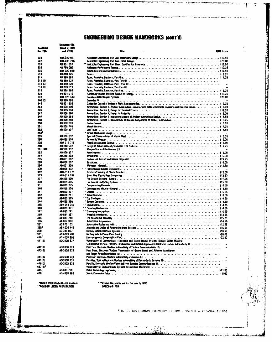
ENGINEERING DESIGN HANDBOOKS Icont'd)0AWmu li-'.O
N& 7W and OTIS) Two , 1IM Prce
201 AOA-022001 tfalicipta r nuie ae r tamPrt onlaPrei n Design ......................................................... $17.50202 A£ A.033 216 Neiceptw Ee eing, Put Two, Beti Deip ................................................... ........ $20.00203 A£ 0901 657 " halicoptar Er ng eim Part Thre, Guaification Asaumnce .................................................... $12.00204 AD.75l00fdlptu, Performwc Testing ................................. ............. 11..75205 ADA.020 020 Timio0 Systarns end Conponents ..................................................................... $17. 50210 AO-0 8 9 245 Fum ......................................................................................... s 9.25211 A0.389 295 Fuem , Proximeity, Electrical, Part N . .................................................................. t 4.75212 (SI A0-389 331 Fi oes, Proximity, Eloctr.cal, Part Two (Ui .............. ................................................... -213 1S) A0-380 330 Fus, Proxialtr, Electrical, Port TW U ................................................................. -"i14 (S) A0-389 333 Fuses, ProX:mity. Electrical, Pai F •r U .......................... .............................).........215 A0-389 296 Fuss, ProxiWtyc~iie.cai, Prt Five . _ ...... .... .............................................. $ 6.25235 A£0864 910 htaNdar 011001 a nSystm Aganst RF m " ......................................................... ... $10.75236 A8A.023 513 a 9ifle W8 rysto ....................................................................... £$20.00240 (CI AD-366 896 Gr ad U) ....I ... ................ ... ... ........................... .......................... -242 A0.801 509 Dripn ior Control of Projctile Flight Characteastics ......................................................... $ 7.25244 A0130 290 Amnsintion, Srto 1. Atilry Aneasition-Geacral, with Tale uf Contents, Glsmsmy, and ide for Series ................. 6.00245 10-389 304 Am ris tsir, Section 2. Deep for Ta En lEtcs ...... ................................................... $12.50247 AD-830 296 Anamm niiien, Sectio 4, iUdgn for Projecti ....................................... ...................... $ 9.0024f AD1830 254 A£munition, Sectio 5, inetin A s of Artillery Ay munition Bex. ................ ................ $ 4.50240 AD-630 266 Anmiaitan, Section 6, MamOfotutg of P etalic t -n0.t.of.A.tiilry.Amm.. tion ............................ ... $ 5.252. . A0..30 303 6.n.-G.. .r. . ................................................................................... 1 6.00
251 AD-838 748 Muzzle Oies .......................... $ 7.25252 £06839 297 Gun Tues ................................................................. $ 6.50253t - Brrich Mec'-n"m Dw ........... I.................................... I.............. . .......... .255 AD-818 532 Spectral Characleristics of Muzzleani .................................................................. $ 6.50260 A0.868 578 Autumatic Wapons ................................................................... .......... $12.00270 ADA.016 716 Prop aNo t Actu at aDe cas .......................................................................... $12.50280 AD£ 840 582 Design of Atod nawclaly Ste• zsd Fre PRorkets .......................................................... $ 9.25281 (SRO) AD£ 389 352 W apon System Effotetn s (U) ....................................................................... -253 AD-830 377 A o yna ics .................................................................................... $ 6.00284 A0D 389 298 Tr etoris ..................................................................................... $ 6.50285 AD£ 861 082 Eeiments ot Aircraft end Iiissilo PToputsion ............................. . .. ......................... $21.25286 AD£ 830 267 Structures ...................................................................................... $ 6.00290 AD0501 329 Warhl .'s-G neral ........................................................................... . $ 12.50300 AD-905 372 Fabrc Deser L iltd Docm it) .. .................................................................... -312 ADAO013 178 Rotational Meoding o Plastic Powders .................................................................. $15.00313 A£0£ 015 181 Short F ibr Plastic Bose Conm osites ................. ................................................... $12.50327 A£ -830 809 Fifa Control o m l ...............Se............................................. ......... $15.25329 AD£ 79 465 Fire Control Compfting Systm ....................................................................... $15.00331 AD-830 275 C senfl a ting Eleenu ts ............................................................................. $ 6.50
340 AD£ 830 276 Carriagesand Momts-Gen al ........................................................................ $ 4.50341 AD-830 ?77 Crtes ..................... .............................................. $ 5.25342 AD-0 30 281 Recoil Systans ..................... ........................ ....................... .......... $ 6.00343 A0.830 393 Top Carriages ................................................................ . .. .............. $ 4.50344 £0 530 396 Bottlfo CeUT* .............................................. . .. ......................... $ 4.50345 ADA.0O13 347 " E oilibra es ....................................................... ....... .................... $ 4.75346 A0.830 301 ElevatingMe h-I ois .............................................................................. $ 4.50347 A0-630 291 Traversaing Mechanim s ............................................... .......... .................. $ 4.50350 AD-861 357 iA ield Am iii s ............................................................................... $13.25355 A01830 268 The Auteenotwa Assearly ........................................................................... 15.25356 AD£ 817 023 Automotive Suspension ............................................................................ $14.50357 A0.873 103 Automotiv s Ba• sand Hulls ................................................ . .. .................. $13.25358 t ADA£ 035 445 Analysis asd Design o Automotive trake System .......................................................... $15.003C0 AD-783 697 Niuii ry Volcle Elocitri l Systms ........ ....... ............................................ $16.50361 ADA-013 769 W I• y Ve•ticle Power Plnt Cooln .................................................................... $20.00410f ADA-038 803 Electromngnetic Co pattiility IEMC) .................................................................... $22.5041; 13I A0C-008 827 Vulribiility of Comomicatiý i-Eictronic eand ElectroOptical System (Except Goided Miss-1)
to Electronic Warfare, Part Oo., Introiscldtion and Gaeal Apasclh to Electronic WastIar Vinerability U) ..................... -412 (C) AOC.008 828 Part Two, Electronic Warfare Veinvabdetv at Tcticad Csres nicatimsU ............................. ............ -413 (3) ADC.008 829 Part Three, Electronic Warfare 'JJlnrability of GroaumdBal and Airfrme S&-reeleace
Kan Target Acvjimata Radars WI ............... I....................................414(IS) OC-006 830 Panr Few, Electronic Warfare Vulrabiflity of Avioni c ..............U.......................................415 (S) ABC.DO8 831 Part Fie, 9plicaflectroic Warfarm Vulneblity of EBectre.Optic System (U) ........................................ -
S418 e6) AOC.08 832 Pat Six, e•tWric Wfarm Vulnerability ot Satelite CeomneicetioIs I) ... ...................................... -417 ISf -- Vulnrebdelty of Guiled Vioae Systemn to Electronic Waif ae (U) ....................................445 A01903 709 SbitnTeclnology, niniwrnj ..................................... ................................ ¶11.0O470£ ADA.029 90, *,etric Convecsion Guide........ ................................................. $ 9.00
lIMOER PREPARATi.N-not aval•se ""sttad Decuments are no for sale by NTIS I .
,11.11t1ISiON LUNPER EPARATION t DARCOMP 706.
S' U. S. GOVERNMENT PRINTIN'! OFFICE 1979 0 - 280-964 (1156)
- ~DANCOM-P 7W6253
FOR THEl COHMA.HDED
OFFICIALs ROBERT L. MOORE"Brigadier General, USAChieZ of Staff
C.0 J. HAROLDLTC, GSAdjutant General
DISTRIBUTION:Special
Ii
LCF0.
S.... ;... ...... . .. .. -'L - • •- 2 •,; • __.•=• . I •'=,• ,, '•, .• .,, • . t•;-•'= "' • •• •:"•''Imll", , "