Brake Press Specs
14
HDS-NT Press Brakes Machine Description General view of machine .................................................................. 2 Electrical enclosure........................................................................... 3 Functions .......................................................................................... 4 Specifications.................................................................................... 5 Machine......................................................................................... 8 Numerical controls ........................................................................ 9 List of standard NC function s .................................................... 9 Dimensions of machine................................................................ 10 Backgauge....................................................................................... 11 One-touch stopper finger s.............................................. .............. 11 Worksheet overhang .................................................................... 12
Transcript of Brake Press Specs
8/2/2019 Brake Press Specs
http://slidepdf.com/reader/full/brake-press-specs 1/14
HDS-NT Press Brakes
Machine Description
General view of machine ..................................................................2
Electrical enclosure...........................................................................3
Functions ..........................................................................................4
Specifications....................................................................................5
Machine......................................................................................... 8 Numerical controls ........................................................................9
List of standard NC functions ....................................................9
Dimensions of machine................................................................10
Backgauge....................................................................................... 11
One-touch stopper fingers............................................................11
Worksheet overhang....................................................................12

8/2/2019 Brake Press Specs
http://slidepdf.com/reader/full/brake-press-specs 2/14

8/2/2019 Brake Press Specs
http://slidepdf.com/reader/full/brake-press-specs 3/14
2
E N E R
A L V I E W
O F M A C H I N E
H Y D R A U L I C U N I T
C Y L I N D E R
B A C K G A U G E
S T O P P E R
U P P E R B E A M
L O W E R B A E M
E M E R G E N C Y S T O P B U
T T O N
F O O T P E D A L
E L E C T R I C A L E N C L O U S U R E
P O S I T I O N D E T E C T O R
P E N D A N T A R M
N C C O N T R O L B O X
8/2/2019 Brake Press Specs
http://slidepdf.com/reader/full/brake-press-specs 4/14
9
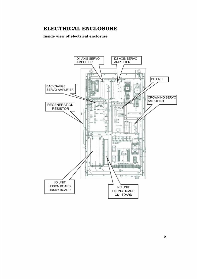
ELECTRICAL ENCLOSURE
Inside view of electrical enclosure
I/O UNIT
HDSCN BOARD
HDSRY BOARD
REGENERATIONRESISTOR
PC UNIT
CROWNING SERVO AMPLIFIER
BACKGAUGESERVO AMPLIFIER
D2-AXIS SERVO AMPLIFIER
D1-AXIS SERVO AMPLIFIER
NC UNIT
BNDNC BOARD
CS1 BOARD
8/2/2019 Brake Press Specs
http://slidepdf.com/reader/full/brake-press-specs 5/14
8
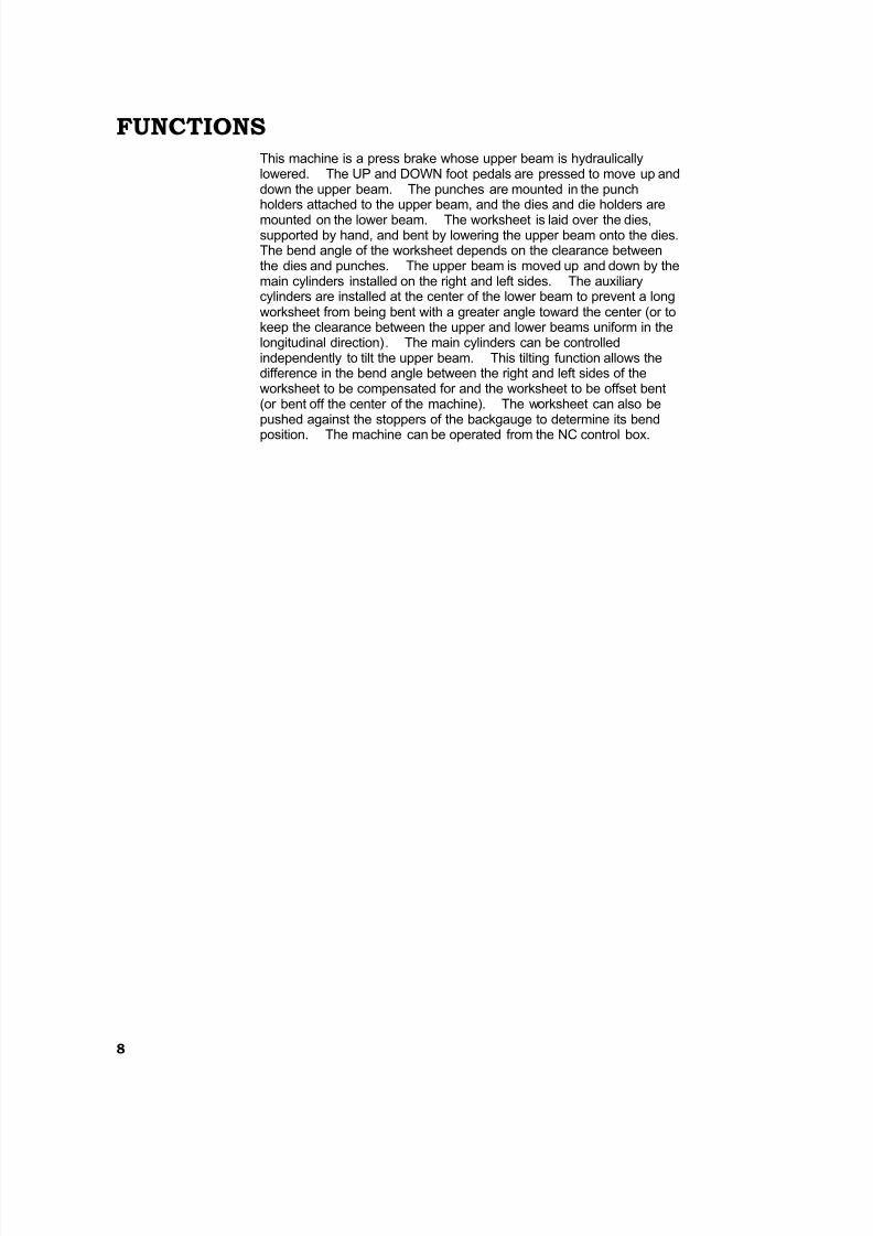
FUNCTIONSThis machine is a press brake whose upper beam is hydraulicallylowered. The UP and DOWN foot pedals are pressed to move up anddown the upper beam. The punches are mounted in the punchholders attached to the upper beam, and the dies and die holders are
mounted on the lower beam. The worksheet is laid over the dies,supported by hand, and bent by lowering the upper beam onto the dies.The bend angle of the worksheet depends on the clearance betweenthe dies and punches. The upper beam is moved up and down by themain cylinders installed on the right and left sides. The auxiliarycylinders are installed at the center of the lower beam to prevent a longworksheet from being bent with a greater angle toward the center (or tokeep the clearance between the upper and lower beams uniform in thelongitudinal direction). The main cylinders can be controlledindependently to tilt the upper beam. This tilting function allows thedifference in the bend angle between the right and left sides of theworksheet to be compensated for and the worksheet to be offset bent(or bent off the center of the machine). The worksheet can also bepushed against the stoppers of the backgauge to determine its bend
position. The machine can be operated from the NC control box.
8/2/2019 Brake Press Specs
http://slidepdf.com/reader/full/brake-press-specs 6/14
9
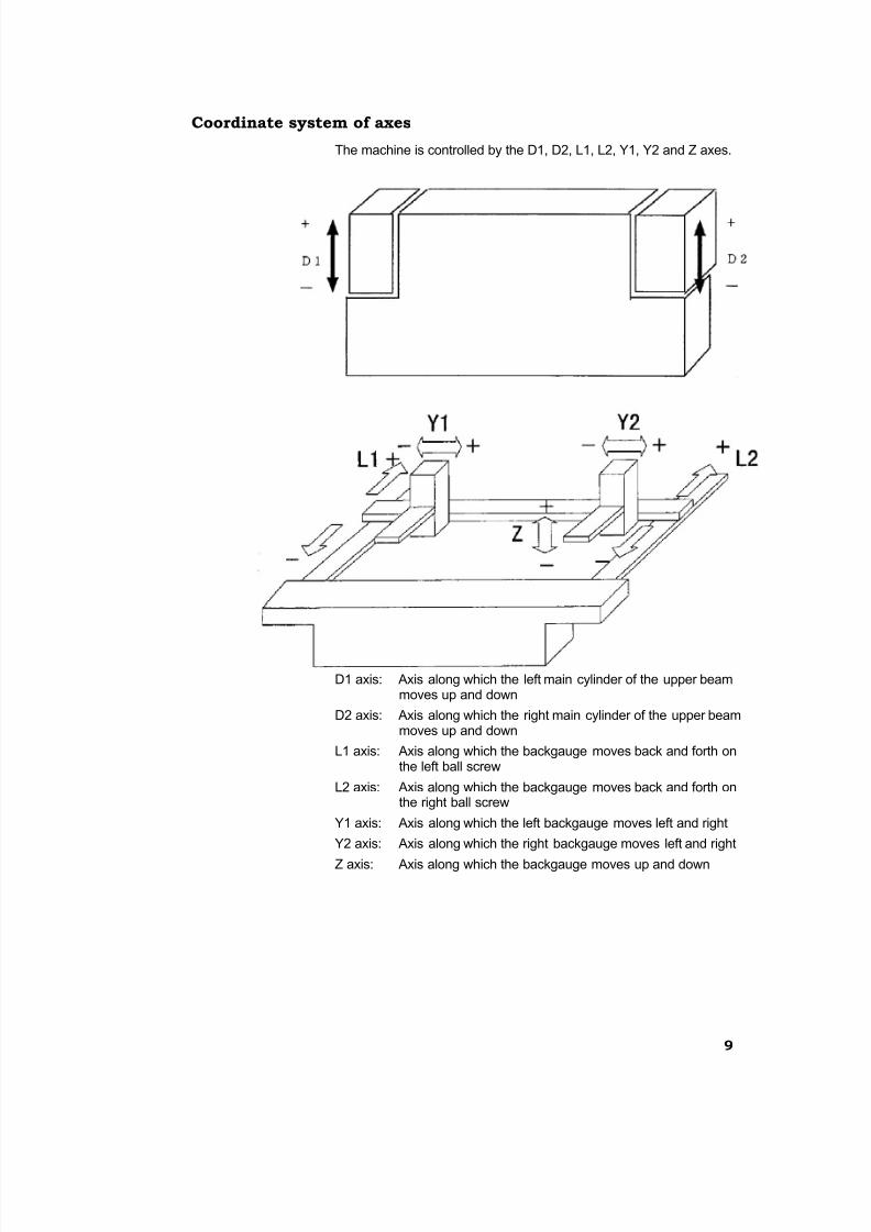
Coordinate system of axes
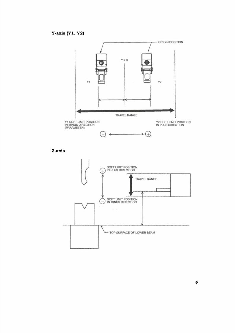
The machine is controlled by the D1, D2, L1, L2, Y1, Y2 and Z axes.
D1 axis: Axis along which the left main cylinder of the upper beammoves up and down
D2 axis: Axis along which the right main cylinder of the upper beammoves up and down
L1 axis: Axis along which the backgauge moves back and forth onthe left ball screw
L2 axis: Axis along which the backgauge moves back and forth onthe right ball screw
Y1 axis: Axis along which the left backgauge moves left and right
Y2 axis: Axis along which the right backgauge moves left and right
Z axis: Axis along which the backgauge moves up and down
8/2/2019 Brake Press Specs
http://slidepdf.com/reader/full/brake-press-specs 7/14
8
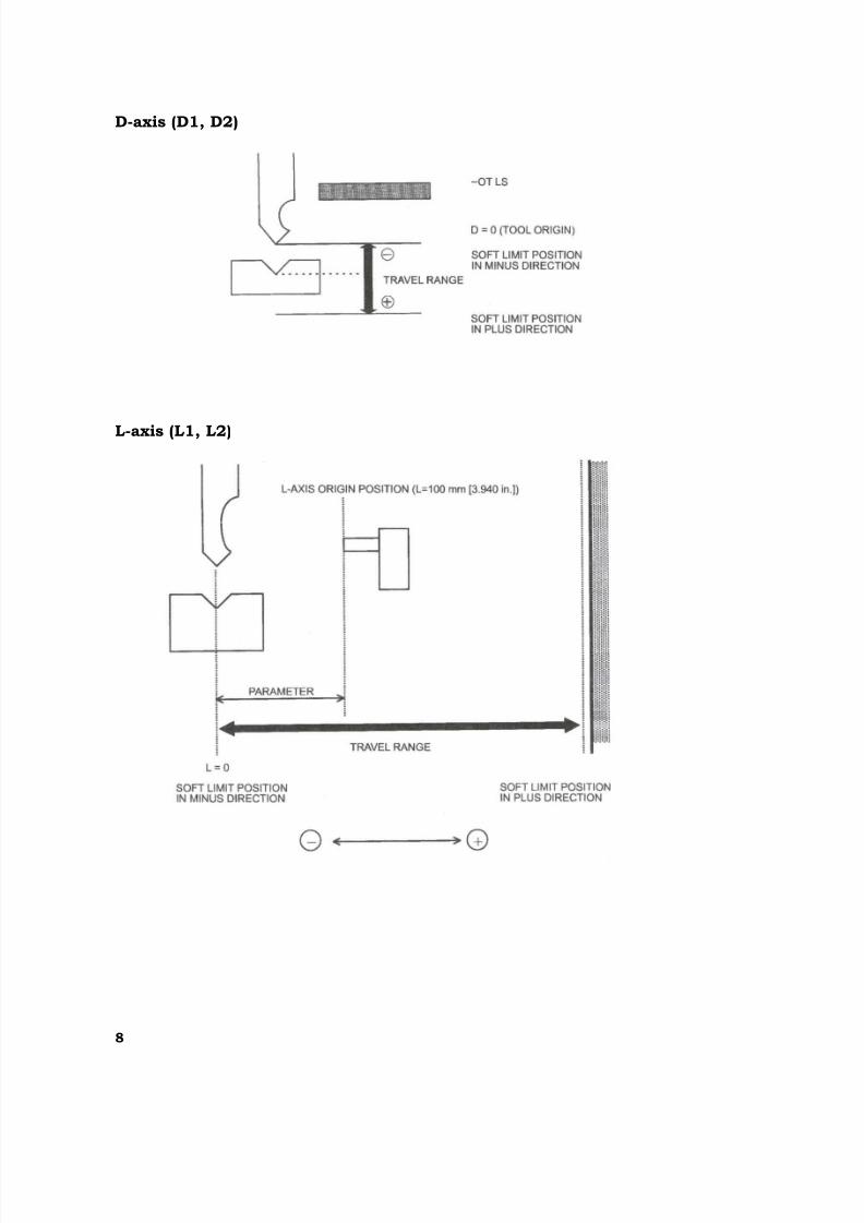
D-axis (D1, D2)
L-axis (L1, L2)
8/2/2019 Brake Press Specs
http://slidepdf.com/reader/full/brake-press-specs 8/14
9
Y-axis (Y1, Y2)
Z-axis
8/2/2019 Brake Press Specs
http://slidepdf.com/reader/full/brake-press-specs 9/14
8
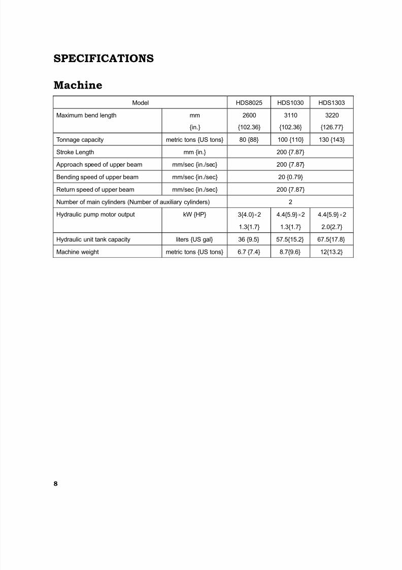
SPECIFICATIONS
Machine
Model HDS8025 HDS1030 HDS1303
Maximum bend length mm
{in.}
2600
{102.36}
3110
{102.36}
3220
{126.77}
Tonnage capacity metric tons {US tons} 80 {88} 100 {110} 130 {143}
Stroke Length mm {in.} 200 {7.87}
Approach speed of upper beam mm/sec {in./sec} 200 {7.87}
Bending speed of upper beam mm/sec {in./sec} 20 {0.79}
Return speed of upper beam mm/sec {in./sec} 200 {7.87}
Number of main cylinders (Number of auxiliary cylinders) 2
Hydraulic pump motor output kW {HP} 3{4.0}×2
1.3{1.7}
4.4{5.9}×2
1.3{1.7}
4.4{5.9}×2
2.0{2.7}
Hydraulic unit tank capacity liters {US gal} 36 {9.5} 57.5{15.2} 67.5{17.8}
Machine weight metric tons {US tons} 6.7 {7.4} 8.7{9.6} 12{13.2}
8/2/2019 Brake Press Specs
http://slidepdf.com/reader/full/brake-press-specs 10/14
9
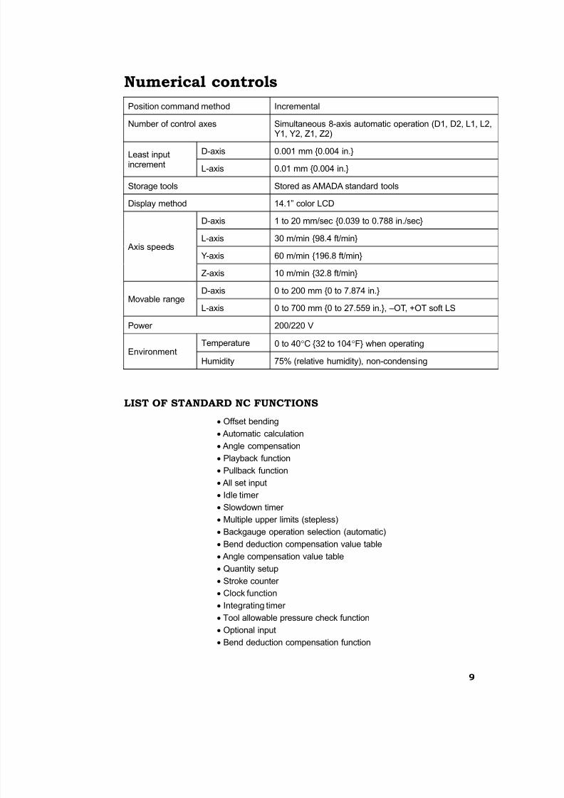
Numerical controls
Position command method Incremental
Number of control axes Simultaneous 8-axis automatic operation (D1, D2, L1, L2,Y1, Y2, Z1, Z2)
D-axis 0.001 mm {0.004 in.}Least inputincrement
L-axis 0.01 mm {0.004 in.}
Storage tools Stored as AMADA standard tools
Display method 14.1” color LCD
D-axis 1 to 20 mm/sec {0.039 to 0.788 in./sec}
L-axis 30 m/min {98.4 ft/min}
Y-axis 60 m/min {196.8 ft/min} Axis speeds
Z-axis 10 m/min {32.8 ft/min}
D-axis 0 to 200 mm {0 to 7.874 in.}Movable range
L-axis 0 to 700 mm {0 to 27.559 in.}, –OT, +OT soft LS
Power 200/220 V
Temperature 0 to 40°C {32 to 104°F} when operatingEnvironment
Humidity 75% (relative humidity), non-condensing
LIST OF STANDARD NC FUNCTIONS
• Offset bending
• Automatic calculation
• Angle compensation
• Playback function
• Pullback function
• All set input
• Idle timer
• Slowdown timer
• Multiple upper limits (stepless)
• Backgauge operation selection (automatic)
• Bend deduction compensation value table
•Angle compensation value table
• Quantity setup
• Stroke counter
• Clock function
• Integrating timer
• Tool allowable pressure check function
• Optional input
• Bend deduction compensation function
8/2/2019 Brake Press Specs
http://slidepdf.com/reader/full/brake-press-specs 11/14
1 0
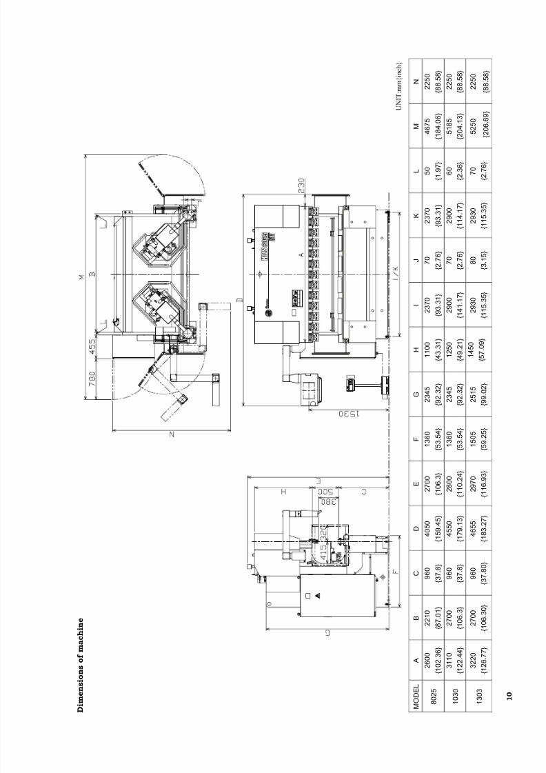
m e n s i o
n s o f m a c h i n e
O D E L
A
B
C
D
E
F
G
H
I
J
K
L
M
N
8 0 2 5
2 6 0 0
{ 1 0 2 . 3 6 }
2 2 1 0
{ 8 7 . 0 1 }
9 6 0
{ 3 7 . 8 }
4 0 5 0
{
1 5 9 . 4 5 }
2 7 0 0
{ 1 0 6 . 3 }
1 3 6 0
{ 5 3 . 5 4 }
2 3 4 5
{ 9 2 . 3 2 }
1 1 0 0
{ 4 3 . 3 1 }
2 3 7 0
{ 9 3 . 3 1 }
7 0
{ 2 . 7 6 }
2 3 7 0
{ 9 3 . 3 1 }
5 0
{ 1 . 9 7 }
4 6 7 5
{ 1
8 4 . 0 6 }
2 2 5 0
{ 8 8 . 5 8 }
1 0 3 0
3 1 1 0
{ 1 2 2 . 4 4 }
2 7 0 0
{ 1 0 6 . 3 }
9 6 0
{ 3 7 . 8 }
4 5 5 0
{
1 7 9 . 1 3 }
2 8 0 0
{ 1 1 0 . 2 4 }
1 3 6 0
{ 5 3 . 5 4 }
2 3 4 5
{ 9 2 . 3 2 }
1 2 5 0
{ 4 9 . 2 1 }
2 9 0 0
{ 1 4 1 . 1 7 }
7 0
{ 2 . 7 6 }
2 9 0 0
{ 1 1 4 . 1 7 }
6 0
{ 2 . 3 6 }
5 1 8 5
{ 2
0 4 . 1 3 }
2 2 5 0
{ 8 8 . 5 8 }
1 3 0 3
3 2 2 0
{ 1 2 6 . 7 7 }
2 7 0 0
{ 1 0 6 . 3 0 }
9 6 0
{ 3 7 . 8 0 }
4 6 5 5
{
1 8 3 . 2 7 }
2 9 7 0
{ 1 1 6 . 9 3 }
1 5 0 5
{ 5 9 . 2 5 }
2 5 1 5
{ 9 9 . 0 2 }
1 4 5 0
{ 5 7 . 0 9 }
2 9 3 0
{ 1 1 5 . 3 5 }
8 0
{ 3 . 1 5 }
2 9 3 0
{ 1 1 5 . 3 5 }
7 0
{ 2 . 7 6 }
5 2 5 0
{ 2 0 6 . 6 9 }
2 2 5 0
{ 8 8 . 5 8 }
U N I T : m m { i n c h }

8/2/2019 Brake Press Specs
http://slidepdf.com/reader/full/brake-press-specs 12/14
8/2/2019 Brake Press Specs
http://slidepdf.com/reader/full/brake-press-specs 13/14
11
BACKGAUGE
One-touch stopper fingers
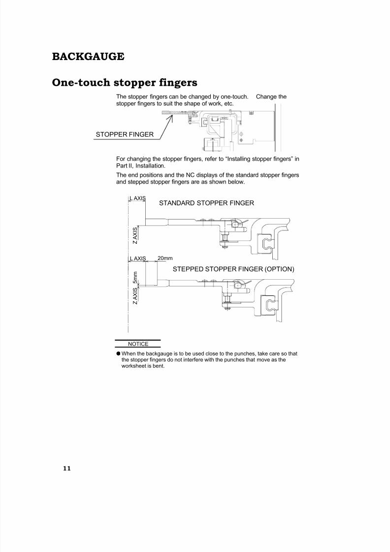
The stopper fingers can be changed by one-touch. Change thestopper fingers to suit the shape of work, etc.
For changing the stopper fingers, refer to “Installing stopper fingers” inPart II, Installation.
The end positions and the NC displays of the standard stopper fingersand stepped stopper fingers are as shown below.
NOTICE
●When the backgauge is to be used close to the punches, take care so thatthe stopper fingers do not interfere with the punches that move as theworksheet is bent.
STOPPER FINGER
20mmL AXIS
Z A X I S
Z A X I S
L AXIS
5 m m
STANDARD STOPPER FINGER
STEPPED STOPPER FINGER (OPTION)
8/2/2019 Brake Press Specs
http://slidepdf.com/reader/full/brake-press-specs 14/14
12
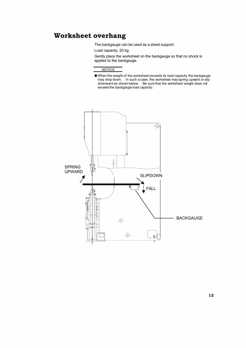
Worksheet overhangThe backgauge can be used as a sheet support.
Load capacity: 20 kg.
Gently place the worksheet on the backgauge so that no shock is
applied to the backgauge.
NOTICE
●When the weight of the worksheet exceeds its load capacity, the backgaugemay drop down. In such a case, the worksheet may spring upward or slipdownward as shown below. Be sure that the worksheet weight does notexceed the backgauge load capacity.
SLIPDOWN
SPRINGUPWARD
FALL
BACKGAUGE