Bracing of steel bridges during construction; theory, full ... · Title and subtitle: Bracing of...
142
Bracing of steel bridges during construction; theory, full-scale tests and simulations Mehri, Hassan 2015 Link to publication Citation for published version (APA): Mehri, H. (2015). Bracing of steel bridges during construction; theory, full-scale tests and simulations. General rights Copyright and moral rights for the publications made accessible in the public portal are retained by the authors and/or other copyright owners and it is a condition of accessing publications that users recognise and abide by the legal requirements associated with these rights. • Users may download and print one copy of any publication from the public portal for the purpose of private study or research. • You may not further distribute the material or use it for any profit-making activity or commercial gain • You may freely distribute the URL identifying the publication in the public portal Take down policy If you believe that this document breaches copyright please contact us providing details, and we will remove access to the work immediately and investigate your claim. Download date: 11. Feb. 2020
Transcript of Bracing of steel bridges during construction; theory, full ... · Title and subtitle: Bracing of...
LUND UNIVERSITY
PO Box 117221 00 Lund+46 46-222 00 00
Bracing of steel bridges during construction; theory, full-scale tests and simulations
Mehri, Hassan
2015
Link to publication
Citation for published version (APA):Mehri, H. (2015). Bracing of steel bridges during construction; theory, full-scale tests and simulations.
General rightsCopyright and moral rights for the publications made accessible in the public portal are retained by the authorsand/or other copyright owners and it is a condition of accessing publications that users recognise and abide by thelegal requirements associated with these rights.
• Users may download and print one copy of any publication from the public portal for the purpose of private studyor research. • You may not further distribute the material or use it for any profit-making activity or commercial gain • You may freely distribute the URL identifying the publication in the public portalTake down policyIf you believe that this document breaches copyright please contact us providing details, and we will removeaccess to the work immediately and investigate your claim.
Download date: 11. Feb. 2020
Bracing of steel bridges during construction
Theory, full-scale tests, and simulations
Hassan Mehri
DOCTORAL DISSERTATION by due permission of the Faculty of Engineering, Lund University, Sweden.
To be defended at lecture hall MA3 at Mathematics Annex building,
Sölvegatan 20, Lund, on 22 January 2016 at 10:15 AM.
Faculty opponent
Professor Emeritus Torsten Höglund
KTH Royal Institute of Technology
Organization: LUND UNIVERSITY Document name: Ph. D. dissertation
Date of issue: December 2015 Author: Hassan Mehri Sponsoring organization: J. Gust Richert Stiftelse-
The Lars Erik Lundbergs Stipendiestiftelse- Byggrådet- Britek AB- Structural Metal Decks Ltd.
Title and subtitle: Bracing of steel bridges during construction - Theory, full-scale tests, and simulations Abstract A number of steel bridges have suffered lateral-torsional failure during their construction due to their lacking adequate lateral and/or rotational stiffness. In most cases, slight bracing can be of great benefit to the main girders involved through their controlling out-of-plane deformations and enabling the resistance that is needed to be achieved. The present research concerned the performance of different bracing systems, both those of commonly used types and pragmatic alternatives. The methods that were employed include the derivation of analytical solutions, full-scale laboratory testing, and numerical modeling. The results of a part of the study showed that the load-carrying capacity of The Marcy Bridge that collapsed in 2002 could be improved by adding top flange plan bracing at 10-20% of its span near the supports. Theoretically, according to Eurocode 3, providing each bar of an X-type plan bracing having cross-sectional area as small as 8mm serves to enhance the load-carrying capacity of the bridge by a factor of 1.28, which is sufficient to prevent failure of the bridge during the casting of the deck. The research also included the derivation of a simplified analytical approach for determining the critical moment of the laterally braced steel girders at the level of their compression flange, which otherwise can usually not be predicted without the use of finite element program. The model employed related the buckling length of the compression flange of steel girders in question to their critical moment. An exact solution and a simplified expression were also derived for dealing with the effect of the rotational restraint of the shorter segments on the buckling length of the longer segments in beams having unequally spaced lateral bracings. The effects of this sort are often neglected in practice and the buckling length of compression members in such systems is commonly assumed to be equal to the largest distance between the bracing points. However, the present study showed that this assumption can provide an unsafe prediction of buckling length for relatively soft bracings and can also lead to a significant overdesign in regard to most bracing stiffness values in practice. Full-scale experimental study on a twin-I girder bridge together with numerical works on different bridge dimensions were carried out on the stabilizing performance of a type of scaffolding that is frequently used in the construction of composite bridges. Minor improvements were discussed which found to be needed in the structure of the scaffoldings that were employed. Findings showed the proposed scaffoldings to have a significant stabilizing potential when they were installed on bridges of differing lateral-torsional slenderness ratios. Axial strains in the scaffolding bars were also measured. Indications of the design brace moment involved were also presented which was approximately between 2 and 4% of the maximum in-plane bending moment in the main girders. Three full-scale experimental studies were also performed on a twin I-girder bridge in which the location of the cross-beam across the depth of the main girders was varied. The effects of several different relevant imperfection shapes on the bracing performance of the cross-beams were of interest. It was found that the design recommendations currently employed can provide uncertain and incorrect predictions of the brace forces present in the cross-bracings. Both the tests and FE investigations carried out showed the shape of the geometric imperfections involved to have a major effect on the distortion that occurred in the braced bridge cross-sections. It was also found that significant warping stresses could develop in cross-beams having asymmetric cross-sections, the avoiding of such profiles in the cross-beams being recommended. Finally, seven full-scale laboratory tests of the end-warping restraints of truss-bracings and of corrugated metal sheets when they were installed on a twin I-girder bridge were also performed. The load-carrying capacity of the bridge was found to be enhanced by a factor of 2.5-3.0 when such warping restraints were provided near the support points. Relatively small forces were developed in the truss-bracing bars in order to such significant improvements in the load-carrying capacity of the bridge to be achieved. Moreover, bracing the bridge in question by means of the metal sheets that were employed was found to result in a significantly larger degree of lateral deflection at midspan than use of the utilized truss bracings did.
Key words: brace, stability, steel, bridge girder, construction Classification system and/or index terms (if any): Supplementary bibliographical information: ISRN LUTVDG/TVBK-1049/16-SE Language: English ISSN and key title: 0349-4969, Report TVBK-1049 ISBN 978-91-87993-04-6 Recipient's notes Number of pages Price Security classification
I, the undersigned, being the copyright owner of the abstract of the above-mentioned dissertation, hereby grant to
all reference sources permission to publish and disseminate the abstract of the above-mentioned dissertation.
Signature Date 4th December 2015
Bracing of steel bridges during construction
Theory, full-scale tests, and simulations
Hassan Mehri
Copy right © Hassan Mehri
Faculty of Engineering, Division of Structural Engineering P. O. Box 118, SE-221 00 Lund, Sweden Report TVBK-1049 ISRN LUTVDG/TVBK-1049/15-SE(250) ISBN 978-91-87993-04-6 ISSN 0349-4969 Printed in Sweden by Media-Tryck, Lund University Lund December 2015
En del av Förpacknings- och Tidningsinsamlingen (FTI)
i
Preface
One of the major concerns in the design of steel bridges is the global and local instability of structural members, both during construction and in service. Catastrophic failures resulting in fatalities have occurred at times when stability principles have been violated during construction. The stability of steel-bridges during construction is highly dependent upon the adequacy in terms of both stiffness and strength requirements of the bracings that are provided. Winter [1] presented a dual brace criterion, his showing experimentally that the load-carrying capacity of an approximately 3.5m long I-shape column (having a depth of 100 mm, a width of 50 mm and a thickness of 1.6 mm) was enhanced by a factor of fifteen by use of bracings as weak as cardboard strips. The efficiency of such slight bracings was impressive. It is possible that some of the bridge tragedies that have occurred could have been avoided by use of very inexpensive bracings. I decided here to investigate how common bracings function in bridge applications during what is the most critical stage in terms of possible instability, namely the construction phase.
The thesis is being submitted for a degree of Doctor of Philosophy at the Division of Structural Engineering of Lund University. It is based on research carried out by the author between May 2011 and December 2015. The thesis itself, the appended papers excluded, is 121 pages in length. No part of the dissertation work has been submitted for a degree at any other university. The research work was supervised primarily by Prof. Roberto Crocetti, to whom I am extremely grateful. I would also like to thank Dr. Eva Frühwald Hansson for her assistance. Special thanks go as well to Dr. Miklos Molnar, the Head of the Division, for his endless support and his kindness. I appreciate too the assistance provided by Per-Olof Rosenkvist (from LTH) and Göran Malmqvist (from SP) during the conducting of the tests. Jamie Turner (from SMD Ltd in the U.K.) and Thomas Lindin (from Britek AB) provided the corrugated metal sheets and scaffoldings that were required during the tests that were employed, I am highly appreciative of their support. I would also like to thank Fredrik Carlsson (from Reinertsen Sverige AB) and Ola Bengtsson (from Centerlöf & Holmberg AB) for the consultancy advice I received from them in our meetings and the discussions we had. I take this opportunity as well to thank my fellow researchers for the great times and the discussions we have had.

ii
Most importantly, thank you Parvaneh for your patience and encouragement. Thanks for believing in me more than myself, and being there supporting me unconditionally.
Hassan Mehri
December 2015
iii
Abstract
A number of steel bridges have suffered lateral-torsional failure during their construction due to their lacking adequate lateral and/or rotational stiffness. In most cases, slight bracing can be of great benefit to the main girders involved through their controlling out-of-plane deformations and enabling the resistance that is needed to be achieved. The present research concerned the performance of different bracing systems, both those of commonly used types and pragmatic alternatives. The methods that were employed include the derivation of analytical solutions, full-scale laboratory testing, and numerical modeling.
The results of a part of the study showed that the load-carrying capacity of The Marcy Bridge that collapsed in 2002 could be improved by adding top flange plan bracing at 10-20% of its span near the supports. Theoretically, according to Eurocode 3, providing each bar of an X-type plan bracing having cross-sectional area as small as 8mm serves to enhance the load-carrying capacity of the bridge by a factor of 1.28, which is sufficient to prevent failure of the bridge during the casting of the deck.
The research also included the derivation of a simplified analytical approach for determining the critical moment of the laterally braced steel girders at the level of their compression flange, which otherwise can usually not be predicted without the use of finite element program. The model employed related the buckling length of the compression flange of steel girders in question to their critical moment. An exact solution and a simplified expression were also derived for dealing with the effect of the rotational restraint of the shorter segments on the buckling length of the longer segments in beams having unequally spaced lateral bracings. The effects of this sort are often neglected in practice and the buckling length of compression members in such systems is commonly assumed to be equal to the largest distance between the bracing points. However, the present study showed that this assumption can provide an unsafe prediction of buckling length for relatively soft bracings and can also lead to a significant overdesign in regard to most bracing stiffness values in practice.
Full-scale experimental study on a twin-I girder bridge together with numerical works on different bridge dimensions were carried out on the stabilizing performance of a type of scaffolding that is frequently used in the construction of composite bridges. Minor improvements were discussed which found to be needed in the structure of the scaffoldings that were employed. Findings showed the
iv
proposed scaffoldings to have a significant stabilizing potential when they were installed on bridges of differing lateral-torsional slenderness ratios. Axial strains in the scaffolding bars were also measured. Indications of the design brace moment involved were also presented which was approximately between 2 and 4% of the maximum in-plane bending moment in the main girders.
Three full-scale experimental studies were also performed on a twin I-girder bridge in which the location of the cross-beam across the depth of the main girders was varied. The effects of several different relevant imperfection shapes on the bracing performance of the cross-beams were of interest. It was found that the design recommendations currently employed can provide uncertain and incorrect predictions of the brace forces present in the cross-bracings. Both the tests and FE investigations carried out showed the shape of the geometric imperfections involved to have a major effect on the distortion that occurred in the braced bridge cross-sections. It was also found that significant warping stresses could develop in cross-beams having asymmetric cross-sections, the avoiding of such profiles in the cross-beams being recommended.
Finally, seven full-scale laboratory tests of the end-warping restraints of truss-bracings and of corrugated metal sheets when they were installed on a twin I-girder bridge were also performed. The load-carrying capacity of the bridge was found to be enhanced by a factor of 2.5-3.0 when such warping restraints were provided near the support points. Relatively small forces were developed in the truss-bracing bars in order to such significant improvements in the load-carrying capacity of the bridge to be achieved. Moreover, bracing the bridge in question by means of the metal sheets that were employed was found to result in a significantly larger degree of lateral deflection at midspan than use of the utilized truss bracings did.
v
Contents
Preface i
Abstract iii
Contents v
Notations ix
Publications xiii
Appended papers xiii Paper I) xiii Paper II) xiii Paper III) xiii Paper IV) xiii Paper V) xiii
Contribution of the authors xiv
Other scientific contributions of the author xiv Conference paper xiv Supervision of M.Sc. thesis xiv
1 Introduction 1
1.1 Objectives 2
1.2 Limitations 3
1.3 State-of-the-art 3
1.4 Terminology 4
1.5 Outline 6
2 Examples of bridge failures during construction associated with instability 9
2.1 Examples of steel-truss bridge failures during construction associated with problems of instability 10
2.2 Examples of failures of built-up steel girder bridges during the non-composite stage associated with their instability 11
2.2.1 The collapse of Bridge Y1504 in Sweden 13
2.3 Steel bridge accidents during concreting that were associated with problems of instability in their timber falseworks 16
2.4 Conclusions 17
vi
3 Theory of beam stability 19
3.1 Introduction 19
3.2 Effects of material inelasticity on bracing requirements 20
3.3 Effects of residual stresses on buckling load 21
3.4 Lateral-torsional buckling of doubly-symmetric simply supported beams subjected to uniform bending 22
3.5 Modifications required in the basic approach to the critical bending moment value 23
3.5.1 Effects of different boundary conditions 24 3.5.2 Effects of different loading conditions 24 3.5.3 Effects of lateral restraints (Paper II) 25 3.5.4 Effects of cross-sectional asymmetry 26 3.5.5 Effects of inelasticity on lateral-torsional buckling 27 3.5.6 Effects of variable cross-section on lateral-torsional buckling (unpublished work) 28
4 Fundamentals of beam bracing 31
4.1 Introduction 31
4.2 Lateral bracing of beams 33
4.3 Torsional bracing of beams 34
4.4 “Column-on-elastic-foundation model” for cross-brace stiffness assessments in steel bridges 36
5 Lateral-torsional instability concerns during construction of steel bridges 41
5.1 Bracings required during concreting of the deck 41
5.2 Bracings required for skewed bridges 43
5.3 Bracings required for in-plane curved bridges 44
5.4 Bracing required prior to the concreting stage 45
6 Bracing options in steel bridges 47
6.1 Intermediate cross-bracings 47
6.2 Support bracings 53
6.3 Bracing of half-through girders 54
6.4 Full-span plan bracings 55
6.5 Partial-span plan bracings (Papers I, and V) 57
6.6 Bracings required in open trapezoidal girders 58 6.6.1 The equivalent plate concept and forces generated in plan-bracings by torsion 59 6.6.2 Forces generated from distortion in the cross-bracings 60 6.6.3 Forces in the plan bracings due to the web inclinations of trapezoidal girders 61
vii
6.6.4 Forces generated in intermediate external cross-bracings from torsion 61 6.6.5 Support cross-diaphragms 62
6.7 Bracing potential of stay-in-place corrugated metal sheets (Paper V) 63 6.7.1. Stiffness requirements of the metal sheets 66 6.7.2. Strength requirements of the metal sheets 66 6.7.3. Connection requirements 67 6.7.4. Use of corrugated metal sheets in Twin-I girder bridges 68
6.8 Scaffolding bracing of steel girders (Paper III) 68 6.8.1 The common practice in design aimed at providing stability for the steel girders during construction stage 69 6.8.2 Shortcomings of the common bridge timber-falseworks 71 6.8.3. The concept of scaffolding bracing of steel bridges 72 6.8.4. Effects of the ledgers on the load-carrying capacity of the test bridge 75 6.8.5 The effects of the ledgers on the bracing forces 78
6.9 Bracing potential of precast concrete slabs 81
7 The effects of initial imperfections on the performance of bracings (Papers III, IV, & V) 83
7.1 Effects of the magnitude and the shape of the initial geometric imperfections on the load-carrying capacity of steel girders 84
7.2 Effects of the shape and the magnitude of initial geometric imperfections on brace forces 86
8 Laboratory tests 89
8.1 Background 89
8.2 Tests performed by the author 90
9 Numerical simulations 95
10 Conclusions and future research 99
10.1 Conclusions from the appended papers 99 Paper I: 99 Paper II: 99 Paper III: 100 Paper IV: 100 Paper V: 101
10.2 Future research 102
Acknowledgements 103
Appendix I 105
Details regarding the test setup 105
viii
Appendix II 111
Test data not reported directly in the appended articles 111
Appendix III 113
AIII.1 Bracing analysis; AASHTO recommendations [82] 113 Summary of the recommendations regarding the use of cross-bracings 113 Summary of the recommendations regarding the use of lateral bracings 114
AIII.2 Bracing analysis; Eurocode recommendations [76] 115 Effects of imperfections in analyzing a bracing system 115 Lateral-torsional buckling of structural components 116
Appendix IV 117
Equivalent plate thickness of typical plan-bracings [2] 117
References 119
ix
Notations
The following symbols are used in the present report:
Areaofacross‐section; Theenclosedareadefinedby thewall‐midlineinathin‐walled
closedsection;
, , , , Cross‐sectionalareaofasingletopflange,abottomflange,andtheweb ofasteelgirder;
, /4 2 ;
, Cross‐sectionalareaofadiagonalandtransversal strut bar; Distancebetweenthestrutsinatrussbracingsystem; Thicknessofawebstiffener;, , , Momentgradientfactorsofabeaminits entirety,andofthe
unbraced andthebracedspans,respectively;
Topflangeloading modificationfactor; Warpingconstants; 1 forIsections.For
trapezoidalcross‐sectionssee 3 ; Depthofacross‐section; Modulusofelasticity; Tangentandreducedmodulusofelasticity;
Distancebetweenthemid‐heightofabeamcross‐sectionandtheplaneofacorrugatedmetalsheet;
Destabilizingforceofacompressionflange; Bracedesignforce;
Shearmodulus; Effectiveshearmodulusofacorrugatedmetalsheet;, Self‐weightofsteelgirdersandthefresh concreteperunitspan
length; Distancebetweenthecentroidsofthetopandthebottom
flanges ofasteelgirder; Depthofacross‐diaphragm; Depthofawebstiffener; Strongaxismomentofinertiaofacross‐beam;
x
., . Momentofinertiaoftheelastic andtheinelastic portionsofacross‐section;
, Momentofinertiaoftheentirecross‐section,andofthecoreportionofahybrid cross‐section;
Bendingstiffnessofverticalwebstiffenersandagirder'sweb;, Momentofinertiaofacross‐sectionwithrespecttothe" "
strong andthe" " weak axes;
, and , Momentofinertiaofthecompressionandthetensionflanges,respectively,withrespectto theweakaxisofamonosymmetricsection;
, , ⁄ , 4 ,
Torsionalconstant; ∑ /3 inopencross‐sectionsand4 / ∑ / inclosedcross‐sections.
Stiffnessofatranslationalspring; Actual orprovided bracestiffnessofalateralbrace;
Idealbracestiffnessofalateralbrace; Designbracestiffnessofalateralbrace;
, Effectivebucklinglengthfactors withrespecttothelongitudinalortheweakaxis;
Longitudinalspan; Distancebetweenthebracepoints;
Distancebetweenpointsofzerotwist orlateraldisplacement ;thecentralspanlength;
, , Effectivebucklinglengthofastructuralmemberbetweenimmovablerestraints;
, , , Effectivebucklinglengthofasystemhaving translationalorrotationalbracings betweentheend‐supports;
, , Criticalin‐planemoment ofabeamrestrainedbymeansofmetalsheets;
, , Criticalin‐planemoment ofabeamrestrainedbymeansoftorsionalbracings;
, , Criticalin‐planemoment ofanunbracedbeam;
, , , Criticalin‐planemomentscorrespondingtolateral‐torsionalbucklingbetweenthebracepoints,andtosystembuckling,respectively;
Warpingbrace momentperlengthofabeam; Maximumappliedin‐planebendingmoment;
Theoreticalplasticbendingcapacityofabeamcross‐section;, , Bendingmomentswithrespectto the , , axesinanun‐
deformedconfiguration;, , Bendingmomentswithrespecttolocalcoordinateaxes
xi
, , inadeformedconfiguration; Diaphragmeffectivenessfactor; Numberofintermediatebracings; Numberofhalf‐sinewavesinabucklingmode;
Numberofmaingirders; Axialcompressivepoint‐load;
, , , Criticalloadofabracedoranunbracedcolumn;kN/rad Shearrigidityofametalsheet equalto / 2 inan
equivalenttrussbracing ; Shearflow; Equivalentuniformloadforgeometricimperfections; Transversalloadper unitspanlength;
Radiusofcurvatureinanin‐plane‐curvedbridge; Radiusofgyration; Transversalspanofabridge; Tributarywidthofmetaldecks pergirder 1 /
wherengisthenumberofgirders;
, Maximumtorquealongthespanduetotheself‐weightofthesteelgirders;
/ Distanceratioofthecentroidsofthetopandbottomflangesfromtheneutral‐axisofabeamcross‐section;
Thicknessoftheplateofacross‐diaphragm; Equivalentplatethickness;
Thicknessofweb‐stiffeners; Webthickness ofagirder;, Lateral andverticaldeformationsofabeamcross‐section; Center‐to‐centerdistancebetweenthecentroidsoftopflanges
intrapezoidalgirders; Lateraldeformationofacolumn;, , Longitudinal,horizontal,andverticalcoordinates; Distanceoftheshearcenter S.C. fromthecentroid. Thelengthofthesidesegments; Torsionalstiffnessofacross‐beam/‐frame/‐diaphragm; Girdersystemstiffness;
Torsionalstiffnesscontributionofwebstiffeners; Effectivetorsionalbrace stiffness 4 ; / ;forbridgeswithsinglebrace, replaceLby0.75L 4 ,
, Actual provided bracestiffnessofatorsionalbrace;
xii
, Idealbracestiffnessofatorsionalbrace; Across‐sectionalpropertythat takesaccountof theeffectsof
cross‐sectionalmono‐symmetry;∆ lateraldisplacementofabracepoint;∆ Magnitudeofinitialout‐of‐straightnessofacompression
member;∆ ∆ ∆ totallateraldisplacementofabracepoint; Sipinaboltedconnection;
Normalstrain; twistatatorsionalbracepoint; Initialtwistofabeamcross‐section; totaltwistatatorsionalbracepoint;
Shearstress; Radiusofcurvatureinabentmember;
Relativeslendernessratio; ;totalpotentialenergy Internalwork‐external
work ; , / ;
Normalstress;∅ Twistofabeamcross‐section; Skewangleofacross‐bracewithrespecttotheverticalaxis.
xiii
Publications
Appended papers
Paper I)
Mehri H. and Crocetti R., "Bracing of steel-concrete composite bridges during casting of the deck," presented at the Nordic Steel Construction Conference 2012, Oslo, Norway 2012.
Paper II)
Mehri H., Crocetti R., and Gustafsson P. J., "Unequally spaced lateral bracings on compression flanges of steel girders," Structures, vol. 3, pp. 236-243, DOI: 10.1016/j.istruc.2015.05.003, 2015.
Paper III)
Mehri H. and Crocetti R., "Scaffolding bracing of composite bridges during construction," Journal of Bridge Engineering (ASCE), DOI: 10.1061/(ASCE)BE. 1943-5592.0000829, 2015.
Paper IV)
Mehri H., Crocetti R., and Yura J. A., "Effects of geometric imperfections on bracing performance of cross-beams during construction of composite bridges," submitted to Engineering Structures, 19th July 2015.
Paper V)
Mehri H., Crocetti R., "End-warping bracing of steel bridges during construction," submitted to Journal of Bridge Engineering, 2nd December 2015.
xiv
Contribution of the authors
The author, Hassan Mehri, planned the test programs, designed the test-setups, performed the laboratory tests, analyzed the recorded test-data, carried out the numerical investigations, and wrote the appended papers and the present thesis. Prof. Roberto Crocetti contributed to the review of the work. Prof. Joseph A. Yura contributed to both the scientific supervision of Paper (IV) and the review of it. Prof. Per-Johan Gustafsson helped the author with the derivation of Eq. (8) in paper (II), and reviewed the analytical solutions of that paper. Dr. Eva Frühwald Hansson reviewed the text of the thesis.
Other scientific contributions of the author
Conference paper
- Mamazizi S., Crocetti R., and Mehri H., "Numerical and experimental investigation on the post-buckling behavior of steel plate girders subjected to shear," presented at the Annual Stability Conference, SSRC 2013, St. Louis, Missouri, April 16-20, 2013 [5].
Supervision of M.Sc. thesis
- Al-rubaye A., "Theoretical and numerical approach to calculate the shear stiffness of corrugated metal decks, " Div. of Struct. Eng., Lund Univ. 2014 [6].
- Winge A., "Temporary formworks as torsional bracing system for steel-concrete composite bridges during concreting the deck, " Div. of Struct. Eng., Lund Univ. 2014 [7].
- Carlson O. and Jaskiewicz L., "The performance of conventional discrete torsional bracings in Swedish steel-concrete composite bridges, " Div. of Struct. Eng., Lund Univ. 2014 [8].
- Ohlin, E., "Metal decks as lateral bracing for composite bridges with trapezoidal cross-sections, " Div. of Struct. Eng., Lund Univ. 2015 [9].
1
1 Introduction
Bridges are an important part of a country's road network. New bridges are often built over busy roads or railways. Traditionally, bridge construction involves the in-place casting of concrete, this requiring both time and a large of space, this often causing serious traffic problems. The economic losses of the traffic delays thus brought about are very difficult to estimate. These include travel disturbances, longer travel times, and the unavailability of transportation, all of which lead to lesser income, and consequently to lesser tax income and social welfare. There are often major losses as well in the form of indirect effects, and the clear negative environmental impact of the traffic jams that take place. To reduce disruptions of this sort, it is extremely important that a bridge's assembly be performed as quickly, smoothly, and as safely as possible.
Developments in the fabrication of steel girders of high strength steel, weldable, and able to achieve a high ratio of the moment of inertia to the cross-sectional area have made the use of steel in the bridge industry attractive. A type of bridge that makes smooth and relatively quick installations possible and that during the last few decades has taken over a large part of the bridge market, is that of the so-called composite steel-concrete bridge. A bridge of this type consists of one or more steel girders in a composite action with a reinforced concrete deck, this serving to optimize use of the materials by the steel girders being subjected predominately to tension, whereas the concrete is subjected mainly to compression. An overall benefit in the use of steel-concrete composite bridges is also the fact that during construction of them the steel girders can be erected rapidly, which ultimately reduces the traffic disturbances brought about. More importantly, the steel girders bear the construction loads of the scaffoldings while construction is taking place, transferring these loads to the abutments. This reduces significantly the amount of scaffoldings that are required.
The installation of steel-concrete composite bridges is, however, a critical matter in the designing of such bridges, it is often controlling the size of both the steel girders and the bracings. Altogether 105 out of the 440 cases of bridge failure dealt with in the report “Failed Bridges, case studies; causes and consequences” [10] occurred during construction of the bridges. This highlights the importance of more detailed investigations at this stage. In recent years, a number of accidents during the construction of steel bridges have occurred due to various instability phenomena during the lifting, launching, or concreting phases in bridge construction. An example of such accidents is the collapse of Bridge Y1504 over
2
the Gide River in Sweden that occurred in 2002; see section (2.2.1). The investigations that took place following the accident required considerable costs and efforts in themselves, and replacing the bridge cost approximately twice the original budget for building of the bridge. Although two workers dropped down to the ground when the bridge collapsed, there were fortunately no fatalities, since the bridge was not particularly high. There have also been failures in the construction of composite bridges due to problems caused by the instability of their falseworks. The falsework failure in connection with the Älandsfjärden Bridge in Sweden in 2008 is an example of such an accident, five construction workers there falling 20 meters down to the ground, two of them being killed, and two severely injured [11]. The author is also aware of the recent bridge collapses in Norway (Trondheim Bridge on May 8, 2013, two persons killed) and in Denmark (in Aalborg in June of 2006, one person killed; and in Helsingør in September of 2014) all of which occurred during concreting of their deck. The author had no access to the failure reports of these accidents at the time of writing the thesis.
The failure mode of lateral-torsional buckling plays an important role in determining the size of the steel bridge girders to employ. The lateral-torsional instability of steel girders involves the possible twisting of the cross-section of them and lateral movement of the compression flange. The lateral-torsional resistance of such slender beams can be improved by either increasing the size of girders, or providing proper bracings so as to reduce the buckling length of the compression flanges. In composite bridges, the top flanges are needed mainly to provide sufficient space for the shear studs when a composite action takes place; their contribution to resisting out-of-plane deformations being negligible once the concrete deck has hardened. On the other hand, providing slight bracings can effectively enhance the resistance of steel girders. Without bracing, too large a lateral deflection of the compression flange could easily occur. A number of bracing options for controlling out-of-plane deformations of the main steel girders are feasible. An effective bracing system should possess adequate stiffness and strength so as to enhance both the load-carrying capacity of the main girders to a desired level and to withstand the forces induced in the bracings.
The present study as a whole involves analytical, experimental, and computational investigations of the bracing requirements of steel bridges during construction. Current knowledge and related design recommendations concerning bracing requirements for steel bridges during construction of them are also discussed.
1.1 Objectives
The main objective of the PhD study was to evaluate the stabilizing performance of the typical bracings (cross-bracings, plan bracings, and corrugated metal sheets)
3
that are commonly used in steel bridge applications during the construction stage. Investigations of possible brace alternatives such as stabilization by means of modified scaffoldings were also of interest. The research includes the derivation of analytical solutions, the carrying out of full-scale laboratory tests, and the performing numerical simulations.
1.2 Limitations
The effects of different loading and boundary conditions, bridge curvature, skewed supports, and the like, on brace forces and/or on load-carrying capacities have been investigated by other authors. Studies concerning the effects of such variations were beyond the scope of the present study. The present study is also concerned mainly with straight bridges. Although in paper III two-span bridges were investigated, for the most part of the present study simply supported bridges were the dominant case studies. However, roughly the same rules as those that apply for the types of bridges studied here apply to the curved, skewed, and continuous bridges as well. Although the effects of the concreting sequence and of launching process on the brace requirements are also relevant to the phenomena investigated here, they were not examined in the present study. The bridges that were studied here were subjected to uniform transversal loads applied to the top flanges, which is a situation very commonly encountered in practice during the concreting stage. Finally, twin girders and trapezoidal girders were selected for the case studies, since these are the girders used most commonly in steel bridges in Sweden.
1.3 State-of-the-art
Although a large number of scientific contributions to study of the stability of steel beams and columns were reviewed in the literature study presented here, only the most relevant references are cited in the thesis. Also, the major contributions of previous research are explained for the most part within the contexts to which they apply. However, in order to classify them in terms of the method that have been employed, a brief account of the state-of-the-art within this context is provided in the following:
Winter [1] developed a simple rigid bar model involving fictitious hinges at the brace points for determining lower-bound stiffness of the bracings that are employed in laterally braced columns, their values corresponding to “ideal” brace stiffness serving as immovable supports. Introducing initial imperfections, Winter also obtained the magnitude of forces present in the bracings. Introducing a
4
rotational spring representing the flexural stiffness of a given column, Pincus [12] extended Winter's model in order to determine the bracing requirements of inelastic columns. Obviously, the main difference between the two models mentioned above is the load-carrying capacity of the unbraced column, which is neglected in Winter's model.
Numerous analytical studies of critical load values or of the required stiffness of bracings in perfect columns or beams under a variety of loading and boundary conditions and of bracing configurations have been carried out, (e.g. [13-22]). Some of the studies resulted in closed-form solutions, but most of them made use of numerical analyses instead. Some of the researches concerned the effects of imperfections on the load-carrying capacity of simple beams and/or on the magnitude of brace forces (e.g. [23-25]). There have also been numerous numerical studies of brace design requirements for imperfect steel bridges (e.g. [26-35]). Few studies, however, have been concerned with software development for the analysis of bridges during their construction (e.g. [36]). Various studies have been carried out on the derivation of simplified solutions for obtaining critical load values or the magnitudes of bracing forces (e.g. [37, 38]). Very few studies, however, have dealt with the bracing performance of steel bridges while taking account of different imperfection shapes that can be involved (e.g. [39]). Similarly, relatively few full-scale experimental works (e.g. [40-44]) were to be found on the performance of bracings in steel bridges.
1.4 Terminology
Some important terms will be explained here to assist readers: - Instability is a condition in which sudden sideway failure occurs in the case
of a member subjected to high compression stresses, typically less than the ultimate capacity of the material involved.
- Critical load is the load at which a structure passes from a stable to an unstable state [45]. After this particular load level (bifurcation point) has been reached, two equilibrium paths are possible. The critical load can be obtained by examining the equilibrium (either an algebraic equilibrium in the case of discrete systems having rigid members or a differential equilibrium in the case of continuous systems having elastic or inelastic members) or by utilizing the principle of minimum potential energy in the case of a virtually deformed system. Bifurcation is a branch point in a load-deflection curve after which when further load is applied two equilibrium states are possible the one with zero deflection that can only occur theoretically in perfect bars, and the other with large deflections.
5
- Post-buckling behavior of structural systems can be studied through adopting the large-deflection assumption in the case of either perfect or imperfect members. Three post-buckling situations can theoretically occur: either a hardening or a softening post buckling, or a transitional case. Plates and the web of a built-up girder for example, can exhibit considerable strength enhancement when the critical load has been exceeded. Whereas shells are imperfection-sensitive, they reach their ultimate resistance values after partial yielding of the cross-section has occurred, this resulting in a softening post-buckling. Slender columns reach their critical load value after only small deformations have occurred.
- Small-displacement (or small-strain) theory: Here the occurrence of displacements is assumed being very small, this allowing the approximations of , , and 1.0 to be used to simplify the mathematical equations involved. Employing small-displacement theory enables the critical load to be obtained. The assumption of large-deflections occurring can provide information regarding post-buckling.
- Principle of minimum potential energy: The total potential energy of an elastic system consists of the internal work, i.e. the strain energy absorbed by the elastic structural members and by the bracings and the external work, , i.e. the work performed by the loads applied along the path traveled from the original un-deformed reference point. According to the principle of minimum potential energy, the deformations corresponding to the maxima and the minima of the total potential energy are the equilibrium positions, the minima corresponding to the stable state.
- Initial imperfections: In practice, all structural members are imperfect in terms of initial geometry, load eccentricities, and residual stresses. The large deflection theory of imperfect systems provides a deformation history including e.g. the loss of stiffness prior to a bifurcation point.
- Falsework or scaffolding: In the thesis, both terms consist of temporary structures used for construction purposes to mold the concrete deck of steel-concrete composite bridges and to support fresh concrete until it has hardened. Two types of such temporary systems tend to be used in practice. In the present text, the term falsework is used when such temporary structures are only built up with use of timber-frames/trusses, the term scaffolding being used when their structure also includes steel-pipe bars.
6
1.5 Outline
The present chapter includes a short description of the problem, the main objectives of the study, the limitations of the study, and an overview of the terminology used in the context.
The second chapter reviews a number of steel bridge collapses reported in the literature associated with problems of instability.
The term lateral-torsional buckling is frequently used in this context. One of the papers included here, Paper II, involves a number of analytical investigations concerning the derivation of solutions regarding the buckling capacity of unequally spaced lateral bracings placed at the level of compression flanges in steel girders. Accordingly, a brief introduction to the theory of beam instability is provided in the third chapter. The information contained in Chapter 3 demonstrates the limitations and the difficulties in deriving closed-form solutions in instability analyses, even in the cases of very simple structural systems.
The fundamentals of beam bracing, lateral-torsional instability considerations during the construction of steel-concrete composite bridges, as well as the typical bracing systems commonly used in such bridges are taken up in Chapters 4-6. The stabilizing potential of corrugated metal sheets and of precast concrete decks here are also discussed. The bracing performance of scaffolding of types frequently used in Sweden is considered in Chapter 6. The results of experimental and numerical investigations of the bracing performance of such scaffoldings are presented in Paper III.
The shape and the magnitude of initial geometric imperfections have significant effects on the load-carrying capacity of the steel bridges and on their bracing forces in particular. This was the main concern in Paper IV. Certain basic information and discussions that could not be provided in Paper IV are presented in Chapter 7.
Relatively little information concerning bridge bracing based on laboratory tests is available. It is highly important that details of the test-setup employed in such works be available for use by other researchers, for example for the purpose of a calibration. In Chapter 8, the test setup designed and employed in the present study is elaborated. The drawing sheets used to build the specimens and the test setup are also shown in Appendix I.
Commercial programs are valuable tools for research engineers, helping them to initiate ideas and to expand parametric studies on models that are already calibrated against test data. In Chapter 9, various concerns regarding the use of finite element program are discussed. In addition, the techniques used in the present study to import geometric imperfections into nonlinear analyses are explained.
7
Finally, in Chapter 10, a summary of the findings and some suggestions for possible future research are presented. Appendices at the end of the dissertation provide the opportunity for further test-setup details and test data to be presented. Appendix III, summarizes the bracing requirements that have been adopted in the current design specifications both in the U. S. and in Europe.
Five papers written by the author during his Ph.D. study are also appended to the thesis.

9
2 Examples of bridge failures during construction associated with instability
Bridge accidents during construction involving the failure of timber falseworks or the overall collapse of a bridge often have had tragic consequences. In recent decades, many bridges have collapsed and many people have lost their lives or been severely injured as the result. In bridge construction with the huge costs and the large numbers of workers it involves, safety should be regarded as being more important than matters of overall construction costs and holding to a time schedule. The bridge disasters recorded in history should remind engineers of the consequences of their mistakes; when mistakes are made, the structure tends to find them. Failure evaluations often report an ignored, underestimated, or unseen engineering approach one that could easily have been avoided. Valuable lessons can be learned, however, in reviewing the history of such errors, this enhancing our understanding of structural responses of this sort under real conditions. In the present chapter, a number of bridge failures that have occurred during bridge construction due either to instability of the bridge itself or to problems in their falseworks are summarized and their causes briefly described. There have also been problems of instability during the construction of bridges having concrete girders due to the bracings being inadequate. This can be seen for instance, in the failure of the four-span Souvenir Boulevard Bridge in Laval, Canada, in the year 2000, in which four outer precast pre-tensioned girders slid off their bearings in each of the interior spans due to inadequate bracing of the precast girders prior to the concreting of the deck [46]. Emphasis in the present chapter is placed, however on the instability of steel bridges and their falseworks.
It should be noted that many bridge accidents and the failure reports regarding them are often not made public in cases in which no fatalities occurred, for fear of possible legal consequences for the firms involved or harm to their reputations. The author faced difficulties at times in obtaining basic technical information as simple as regarding the cause of failure in cases that involved fatalities. Except for the bridge failure discussed in Section (2.2.1), in which the author had access to the failure reports, the information regarding other failure cases are from sources of other types that are referred to.
10
2.1 Examples of steel-truss bridge failures during construction associated with problems of instability
There have been a number of truss bridge failures due mainly to buckling of their compression chords or diagonals [10]. These include for example, the following:
- Total collapse of a semi-parabolic truss bridge in Switzerland between Rykon and Zell, 21 m in overall length that occurred in 1883, a collapse due to buckling of the upper chord because of inadequate lateral stiffness, one person being killed;
- Total collapse of a semi-parabolic truss bridge, called the Mountain Bridge, having a total length of 28 m, that occurred in Austria in 1891, due to the buckling of compression members because of inadequate lateral stiffness;
- Total collapse of a parallel truss bridge over Cannich in Scotland, 40 m in total length, that occurred in 1892, due to the buckling of the top chord because of inadequate lateral stiffness;
- Partial collapse of a semi-parabolic truss bridge, over the Morava River near Ljubicevo in Serbia, 85 m in total length, that occurred in 1892 due to buckling of the compression chord;
- Total collapse of a cantilever truss bridge over the St. Lawrence River near Quebec in Canada, 853 m in total length and having an inner span of 550 m, that occurred in 1907 due to failure of the under-dimensioned compressed bottom chord during construction, killing 74 persons. The cross-section of the chord was built-up of four non-compact web plates.
- Partial collapse of a six-span semi-parabolic truss bridge with a total length of 554 m near Ohio Falls in Mississippi, U.S., that occurred in 1927, due to lack of under-water bracings, killing one person.
There were no further reports that the author found of failure of steel-truss bridges due to problems of instability. This probably indicates that the buckling of compression chords as well as the lateral bracings they require are now well understood by engineers, resulting in better production of bridges of this type.
11
2.2 Examples of failures of built-up steel girder bridges during the non-composite stage associated with their instability
A number of bridge failures associated with problems of instability in the main girders are listed below, a brief description of each case being provided. Most of the failures occurred during erection of the bridges, although in some of the cases failure occurred during demolition.
- A five-span twin I-girder motorway Bridge with a total length of 272 m collapsed near Kaiserslautern over the Lauterbach Valley in Germany in 1954. Total collapse of the inner span together with a lateral buckling of the bottom flange of the side span occurred during erection of the bridge. The compressive stresses in the bottom flanges of the side span were generated through deliberate lifting of the internal supports and the applying of an extra temporary gravity load to the suspended inner span, in order to induce a pre-stressed condition in the finished concrete deck. The spacing of the braces was increased from 4 m in the design of the bridge to 8-12 m in the construction phase without any plan bracings being placed at the level of the bottom flanges near the supports [10].
- A three-span twin box-girder steel bridge, The Fourth Danube Bridge, having a total span of 412 m, approximately 32 m width, and 5 m depth failed in Vienna in November 1969 [47]. The top flange of the final section was shortened by 15 mm to fit the gap in which the cantilevers met in the middle. This change was undertaken to adjust the closing section to the cross-sectional rotations of the cantilevers, due to vertical deflections of the large cantilevers brought about by their own weight as well as by thermal elongations of the cantilevers during the day. The drop in temperature in the evening and reversing of the thermal deformations generated tensile stresses in the top flange together with compression in the bottom flange. The bridge experienced major failures due to buckling at both the side-spans and the inner-span near the regions having a zero bending moment. The width-to-thickness ratio of the bottom flange stiffeners was also relatively large in this case.
- A seven-span single trapezoidal girder bridge, The Cleddau Bridge in Wales, UK, with a total bridge length of 819 m, failed in June 1970 [47]. The huge cantilever arm with a length of 61 m, a width of approximately 20 m, and a depth of 6 m fell to the ground during launching due to buckling of the cross-girder at a bearing point, killing four people.
- A five-span three-cell trapezoidal steel bridge, cable-stayed in the three inner spans, The West Gate Bridge over the Yarra River in Melbourne,
12
Australia, with total bridge length of 848 m, failed in October 1970 [45]. The girders of one span, 112 m in length, buckled after leveling two half-girders through the self-weight of eleven concrete blocks. Thirty-five workers perished, some of them while working on the bridge or inside the boxes, and many while on a lunch break beneath the span, where they were crushed by the falling span.
- A three-span trapezoidal girder bridge, the Storm Bridge over Rhine, with a total bridge length of 442 m, collapsed in Germany in 1971 [10]. Because of buckling of the stiffened bottom flange, the cantilever girder broke off causing partial collapse of the bridge, killing 13 persons. The longitudinal stiffeners were not welded to the bottom flange at the joint of two cross-sections, leaving a 400 mm long section of the bottom flange unstiffened.
- A six-span trapezoidal girder bridge, the Zeulenroda Bridge over the Weida Reservoir in Germany having a total bridge length of 362 m, failed in 1973 [10]. The 31.5 m cantilever arm of the second span of the bridge collapsed due to buckling of the stiffened bottom flange (the critical load value, instead of the design value, had been used to determine the size of the stiffeners), killing four persons.
- A two-cell steel box girder of a composite bridge at Bramsche over the Mittelland Canal in Germany having a total bridge length of 60 m, failed in 1974 [10]. The concrete deck had been removed during demolition, leaving the top flanges without lateral restraint, one person was killed.
- A 97 m long steel girder 2.4-3.65 m in depth collapsed during the erection of the Syracuse Bridge (with a total bridge length of 670 m) in New York in 1982 [10] due to inadequate bracing, one person being killed.
- Lateral-torsional buckling of a girder weighing 120 tons occurred during the demolition of a bridge near Dedensen over the Mittelland Canal in Germany in 1982 [10] after the lateral connections of it had been removed.
- A single steel girder weighing 43 tons fell down during construction of the Astram Line Metro Railway Bridge in Hiroshima, Japan in 1991 [48] due to problems of instability, killing 14 persons.
- A three-span triple I-girder bridge, The State Route 69 Bridge over the Tennessee River, having a total bridge length of 367 m, collapsed in Tennessee on May 1995 [10]. The bottom flanges were braced substantially by means of relative lateral bracings, but no lateral bracing was specified for the top flanges. Cross-frames had been built up by use of double angle profiles. Total collapse occurred during erection of the bridge when a cross-frame had been removed in order to fix the connection, one person being killed.
13
- A steel girder weighing 50 tons dropped onto the road during a demolition in Harrisburg, Pennsylvania in 1996 [10]. The failure occurred because of the girder's flange being cut at two points, causing a reduction in lateral stiffness, one person being killed.
- Bridge Y1504 in Sweden, with a trapezoidal girder and a total bridge length of 65 m experienced global lateral-torsional buckling on June 2002 during concreting of the deck [11]. The stay-in-place metal decks were designated to also provide lateral bracing of the compression top flanges, yet the type of corrugated sheets and the number of fasteners had been reduced during construction. Fortunately, although a few workers fell to the ground below, the accident had no fatalities because of low height of the bridge.
- The Marcy Bridge in New York with a trapezoidal girder and a total bridge length of 52 m experienced global lateral-torsional buckling during concreting of the deck in October 2002, one person being killed [49]. No plan bracing between the two end supports had been used in this pedestrian bridge.
- A single steel I-girder (30 m long weighing 40 tons) of the Interstate 70 Bridge in Denver dropped from a freeway bridge into the traffic below in 2004 causing a car to crash, killing three persons [48]. The accident occurred during the widening of the existing bridge. The girder was temporarily braced to the existing bridge at five points. However, the expansion bolts that attached the bracings to the existing concrete deck were not sufficiently embedded in the deck.
- Three out of seven I-girders of 102nd Avenue over Groat Road Bridge in Canada buckled in 2015 due to lack of permanent bracings while the girders were being erected [50]. The subcontractor (the largest private firm in Canada, with 40 years of experience) misread the specifications regarding the required bracings. For the one year delay this brought up, the contractor is required to pay almost $4.2 million in penalties.
2.2.1 The collapse of Bridge Y1504 in Sweden
In this section the original report issued after evaluation of the Bridge Y1504 accident [9] by both the firms involved and the independent parties are reviewed. Bridge Y1504 over the Gide River in Sweden, located 90km west of the city of Umeå, collapsed on June 12, 2002. The bridge had a 65m long trapezoidal cross-section provided with nine intermediate cross-diaphragms to control distortion. Corrugated metal sheets served both as lateral restraints to the top-flanges and as a stay-in-place formwork for the fresh concrete while the bridge was being built. The average self-weight of the fresh concrete, including both the reinforcement
14
and the metal sheets was approximately 55kN/m. The steel girders had an average weight of 17kN/m. It was planned the concreting would be carried out in two steps; first, by covering approximately half of the span symmetrically through pouring at the mid-span. The cross-section of the bridge suddenly rotated by 90° at mid-span, after only a quarter of the volume planned for the first step had been poured. The end-bearings were also severely damaged due to warping of the cross-section. According to witnesses, the entire accident took place within just several seconds. Six workers fell into the river, but fortunately were not injured.
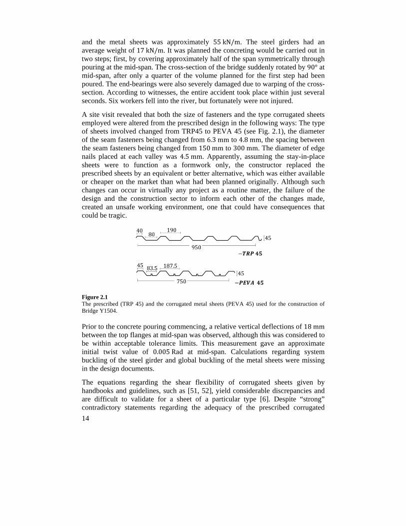
A site visit revealed that both the size of fasteners and the type corrugated sheets employed were altered from the prescribed design in the following ways: The type of sheets involved changed from TRP45 to PEVA 45 (see Fig. 2.1), the diameter of the seam fasteners being changed from 6.3mm to 4.8mm, the spacing between the seam fasteners being changed from 150mm to 300mm. The diameter of edge nails placed at each valley was 4.5mm. Apparently, assuming the stay-in-place sheets were to function as a formwork only, the constructor replaced the prescribed sheets by an equivalent or better alternative, which was either available or cheaper on the market than what had been planned originally. Although such changes can occur in virtually any project as a routine matter, the failure of the design and the construction sector to inform each other of the changes made, created an unsafe working environment, one that could have consequences that could be tragic.
Figure 2.1 The prescribed (TRP 45) and the corrugated metal sheets (PEVA 45) used for the construction of Bridge Y1504.
Prior to the concrete pouring commencing, a relative vertical deflections of 18mm between the top flanges at mid-span was observed, although this was considered to be within acceptable tolerance limits. This measurement gave an approximate initial twist value of 0.005Rad at mid-span. Calculations regarding system buckling of the steel girder and global buckling of the metal sheets were missing in the design documents.
The equations regarding the shear flexibility of corrugated sheets given by handbooks and guidelines, such as [51, 52], yield considerable discrepancies and are difficult to validate for a sheet of a particular type [6]. Despite “strong” contradictory statements regarding the adequacy of the prescribed corrugated
15
sheets in stabilizing the girder, and also regarding the responsibility of the firms involved, there appeared to be a “general” agreement between the various failure reports that were issued for the causes of the accident. A review of the failure reports issued by the independent third parties that were involved showed the actual shear stress values to probably be greater than the shear resistance of the critical edge fasteners. This was probably true, even ignoring the torque that could be generated from the wind load. The folded stiffeners in the type of sheets that were utilized considerably increases (by a factor of approximately 1.8) the warping flexibility of the sheets considerably compared with similar sheets that lack such stiffeners. This increase in flexibility led to strong forces being directed at the edge fasteners, since the panel was not sufficiently stiff to properly distribute the shear stresses between the edge fasteners of each panel. Use of two nails instead of one for each stiffener, one on each side, would have been able to increase the shear stiffness of the panel appreciably and presumably reduce the risk of failure.
During concreting, in addition to the in-plane bending stresses (which were greatest in the mid-span and were zero at the supports), the steel girder with a semi-closed-section was subjected to shear stresses created by torsion (which was greatest at the supports and “zero” at mid-span). Assuming the steel girder to have a thin-walled closed-section, the torque can be assumed to develop shear flows of ∙ ∑ /2 across the section, being a modification factor to take into account stress concentration effects due to appreciable changes of thickness in the cross-section, and being the enclosed area defined by the wall-midline in a closed section. This shear force should be resisted by both the attachments and the St-Venant stiffness of the closed cross-section. The torques, , are generated by the following:
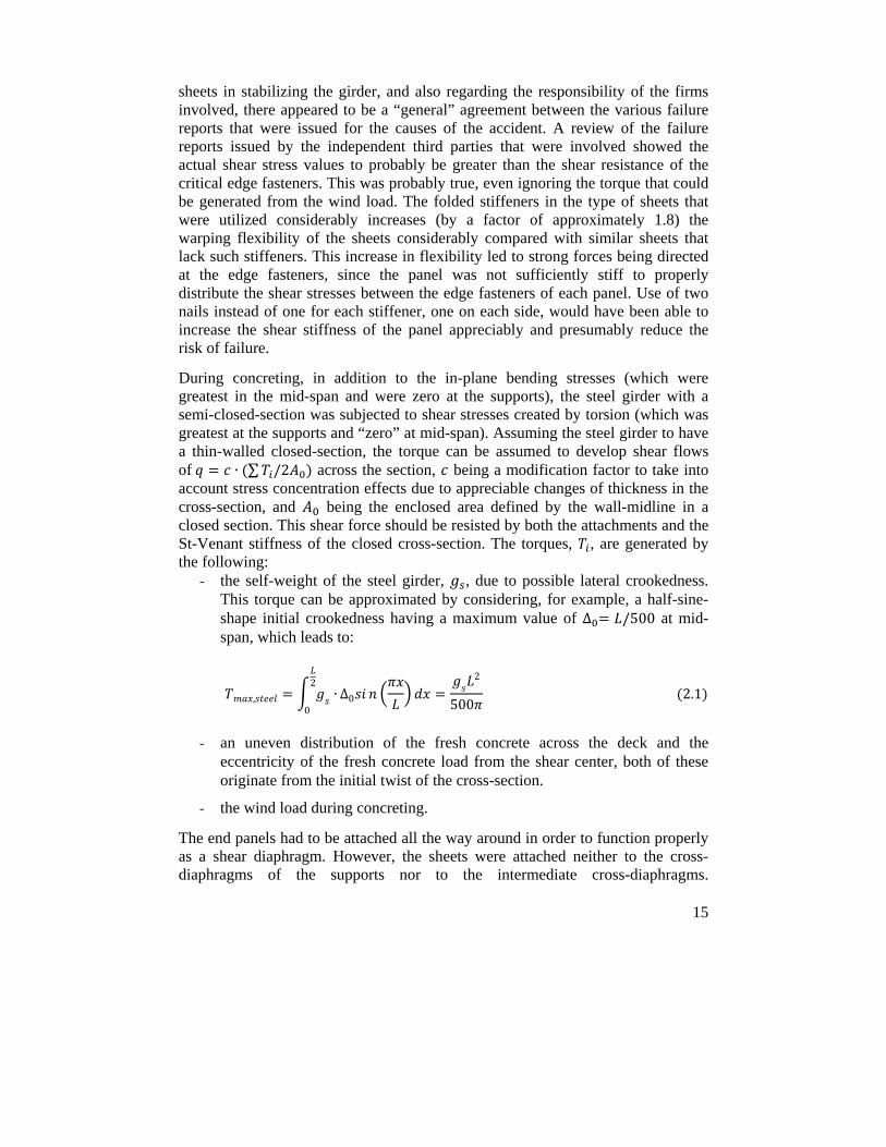
- the self-weight of the steel girder, , due to possible lateral crookedness. This torque can be approximated by considering, for example, a half-sine-shape initial crookedness having a maximum value of ∆ /500 at mid-span, which leads to:
, ∙2
0
∆0
2
500 2.1
- an uneven distribution of the fresh concrete across the deck and the eccentricity of the fresh concrete load from the shear center, both of these originate from the initial twist of the cross-section.
- the wind load during concreting.
The end panels had to be attached all the way around in order to function properly as a shear diaphragm. However, the sheets were attached neither to the cross-diaphragms of the supports nor to the intermediate cross-diaphragms.
16
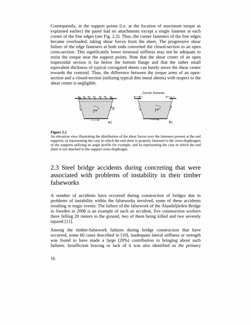
Consequently, at the support points (i.e. at the location of maximum torque as explained earlier) the panel had no attachments except a single fastener at each corner of the free edges (see Fig. 2.2). Thus, the corner fasteners of the free edges became overloaded, taking shear forces from the sheet. The progressive shear failure of the edge fasteners at both ends converted the closed-section to an open cross-section. This significantly lower torsional stiffness may not be adequate to resist the torque near the support points. Note that the shear center of an open trapezoidal section is far below the bottom flange and that the rather small equivalent thickness of typical corrugated sheets can barely move the shear center towards the centroid. Thus, the difference between the torque arms of an open-section and a closed-section (utilizing typical thin metal sheets) with respect to the shear center is negligible.
Figure 2.2 An elevation view illustrating the distribution of the shear forces over the fasteners present at the end supports, a) representing the case in which the end sheet is properly fastened to the cross-diaphragms of the supports utilizing an angle profile for example, and b) representing the case in which the end sheet is not attached to the support cross-diaphragm.
2.3 Steel bridge accidents during concreting that were associated with problems of instability in their timber falseworks
A number of accidents have occurred during construction of bridges due to problems of instability within the falseworks involved, some of these accidents resulting in tragic events. The failure of the falsework of the Älandsfjärden Bridge in Sweden in 2008 is an example of such an accident, five construction workers there felling 20 meters to the ground, two of them being killed and two severely injured [11].
Among the timber-falsework failures during bridge construction that have occurred, some 60 cases described in [10], inadequate lateral stiffness or strength was found to have made a large (20%) contribution to bringing about such failures. Insufficient bracing or lack of it was also identified as the primary
17
enabling event with respect to the collapsing of bridge falseworks observed in a survey of bridge falsework failures reported since 1970 [53].
2.4 Conclusions
The author found no information regarding failures of steel-truss bridges being due to inadequate lateral bracing or to buckling of their compression members during the last few decades. This indicates clearly that the stability requirements of such bridges are rather well understood by engineers.
However, built-up bridge girders still fail due to inadequate bracings, or errors in the proper evaluation of the local and global buckling capacity of the steel girders. Global lateral-torsional buckling of trapezoidal girders was the failure mode in two recent bridge accidents.
The stabilizing function of corrugated metal sheets is strongly affected by their shear stiffness and strength as well as by the shear resistance of their attachments. Calculations regarding the shear stiffness of metal sheets are rather complex, and the shear stiffness of them depending upon a number of factors, such as their geometry, the number of attachments, and warping of the section involved. Further studies are needed in order to enhance the knowledge for such members when they function both as a stabilizing system and as a stay-in-place formwork during the construction of steel bridges.
The failure of Bridge Y1504 taught us that any major change in common design practice should be highlighted in design documents. Lack of proper communication between the design and the construction sectors can potentially create am unsafe working environment in construction operations.
Several accidents have occurred during demolition of steel bridges. This shows that constructors may well ignore the stability assessments of steel girders during demolition. There, the steel girders involved can be vulnerable to lateral-torsional buckling once the lateral support, provided by a concrete deck for example, is removed. In situations of other types, failures of this sort can occur when the size of a compression flange is reduced locally during demolition, resulting in a significant loss in lateral-torsional stiffness.
The recent failures that have occurred during the concreting stage indicate there to be a need for further investigations concerning the stability of bridge falseworks. Despite the importance of stability assessments of bridge falseworks, guidelines regarding the stability requirements of such systems during construction are ignored in a great extent both in Eurocodes and in other code specifications. Regardless of having sophisticated plans for management, design, construction, maintenance, cost analyses, and the like, a simple human error in the design or in

18
the installation of timber falseworks can lead to catastrophic events. Accidents of this sort very frequently result in fatalities, considerable delays, and significant extra costs for replacement of what has been destroyed and for failure evaluations. Despite the elementary techniques used in the structure of bridge falseworks, these often represent a considerable portion of the construction costs of a composite bridge. Alternative systems of greater efficiency and safety to the currently used falseworks can be of great help during construction of steel-concrete composite bridges.
19
3 Theory of beam stability
A stability criterion represents a limit state such that at a certain load a structure passes from a stable state, involving a situation in which a small increase in load generates only a small increase in displacement, to an unstable state one, in which a small increase in load results in a large change in displacement [45]. Generally, stability analyses include either studying of the local buckling of a cross-sectional component in the presence of compressive stresses, or determination of the critical load of structural members of systems (such as a column, beam, frame, arch, or truss) that corresponds to their lack of stability. The major concern of the present research is the lateral-torsional buckling of steel bridge girders. In line with this, basic concepts concerned with the lateral-torsional instability of beams are taken up briefly in the present chapter. The text begins with a brief introduction to matters of elastic and inelastic buckling followed by a discussion of the effects of residual stresses on the critical load values involved.
3.1 Introduction
In 1729, a Dutch scientist, Pieter van Musschenbroek, performed pioneering work on the buckling of compression struts, his discovering that the failure load involved is inversely proportional to the square of the length of the struts [54]. Adopting the assumption of a proportional relationship between the curvature at any point of a bent member and the resisting moment that develops a relationship that Jacob Bernoulli introduced in 1705 the Swiss mathematician Leonard Euler presented a formula in 1757 for predicting the elastic critical load value of perfect columns: , / [55]. Euler was uncertain about the term , “a dimension constant which seems to be proportional to the square or even cube of thickness and should be obtained experimentally” [55]. In the early 1800's, Euler's formula was widely criticized by engineers and authorities, such as Coulomb who believed that the failure load of a column depends only on the cross-sectional area and not the length of the column. This occurred since the formula failed in experiments to correctly predict the failure load of columns composed of materials in use at the time, i.e. masonry and timber. Materials to which Euler's formula has found to be most applicable, such as structural steel, first became commercially available some 100 years after Euler's contributions within this area.
20
More than a century after Euler presented his formula for elastic buckling of columns, Ludwig von Tetmajer [56, 57] carried out experimental investigations concerning the causes of the Münchenstein truss railway bridge disaster in June 1891, which killed over 70 persons. The study revealed that the Euler's formula, that had been used to design such bridges at the time, needed to be modified for columns having an intermediate slenderness ratio, e.g. one of 0.3 1.4.
3.2 Effects of material inelasticity on bracing requirements
Euler stated the following:
“The stiffness moment”, / , “is not limited to elastic bodies, and it concerns a bending by means of which any body resists a change in curvature to reestablish its original shape” [55].
For columns that experience a bifurcation of equilibrium above the proportional limit, Euler's formula provides a prediction that overestimates the critical load due to the regression of strain in the inelastic range, i.e. when / ; where
is the tangent modulus, and and are the normal stress and strain values. To expand Euler's concept to be applicable within the inelastic range, Engesser proposed a tangent modulus concept in 1889 [45] from which the critical slenderness ratio of a column, / , can be calculated using Eq. (3.1), where is the tangent modulus obtained from the - / curve for a given stress value, and being the radius of gyration of the cross-section.
/ / 3.1
Performing 32 column tests in 1889, Considere suggested that if buckling occurs above the proportional limit, the elastic modulus in Euler's formula should be replaced by an effective modulus, , which is a value between the elastic and the tangent moduli [45]. This theory is now referred to as the reduced/double modulus concept, which improves the tangent modulus concept by considering both material and cross-sectional properties, see Eq. (3.2). The double-modulus concept makes use of the elastic modulus for the elastic zone of the cross-section, which has a moment of inertia of ., and a tangent modulus for the inelastic part, which has a moment of inertia of ..
. . 3.2
21
Pincus [12] stated that since the flexural stiffness of a member decreases in the inelastic range, its critical load is smaller than the elastic critical load predicted by the Euler's formula. Thus, to achieve a desired critical load of a column loaded in its inelastic range and to compensate for the loss in stiffness of the column, braces stiffer than the “ideal” value for it (= , which serves the brace points similar to an immovable support), as predicted by Winter's model (see Section 1.3), should be provided. Gil and Yura [58] reviewed Pincus's claim. In their experimental studies, artificial inelasticity for a test-column was created through use of high-strength steel inside of the cross-section and low-strength steel on the outsides. For the cases studied, in contrast to Pincus's claim, the results showed that the full bracing requirements were independent of the state of material (i.e. whether it was elastic or inelastic).
3.3 Effects of residual stresses on buckling load
A large number of tests [56] showed that the load-carrying capacity of columns having an intermediate slenderness ratio was considerably smaller than the column strengths predicted on the basis of Eq. (3.2). This occurs due to the detrimental effects of residual stresses combined with the geometric imperfections and material nonlinearities that are present. The effects of residual stresses on the critical load values and on bracing requirements may in practice not be possible to determine for a given case. A number of studies have discussed the effects of residual stresses on the strength of very simple column members. For instance, Galambos [45] investigated analytically the effects of an assumed residual stress distribution on the load-carrying capacity of a column with a rectangular cross-section with respect to its either the weak or the strong axis. The residual stresses were distributed linearly across the cross-section from a tensile stress value 0.3~0.5 times that of the yielding stress at the center of the cross-section to a compressive stress of the same magnitudes at the edges. Such studies, together with extensive laboratory tests of varying mechanical properties (such as slenderness, and cross-sectional shape) and fabrication processes resulted in the development of column and beam design curves in the current code specifications. These design curves take account of, for example, the effects of geometric imperfections, typical load eccentricities, and residual stresses on the design load value of typical columns and beams used for practical purposes.
In the numerical investigations of the present study, the effects on the performance of bracings in steel bridges, of the shape and magnitude of geometric imperfections, along with of the material and geometric nonlinearities involved, were included in the analyses. Taking account of the effects of residual stresses was seen, however, as being outside the scope of the present Ph.D. research.
22
3.4 Lateral-torsional buckling of doubly-symmetric simply supported beams subjected to uniform bending
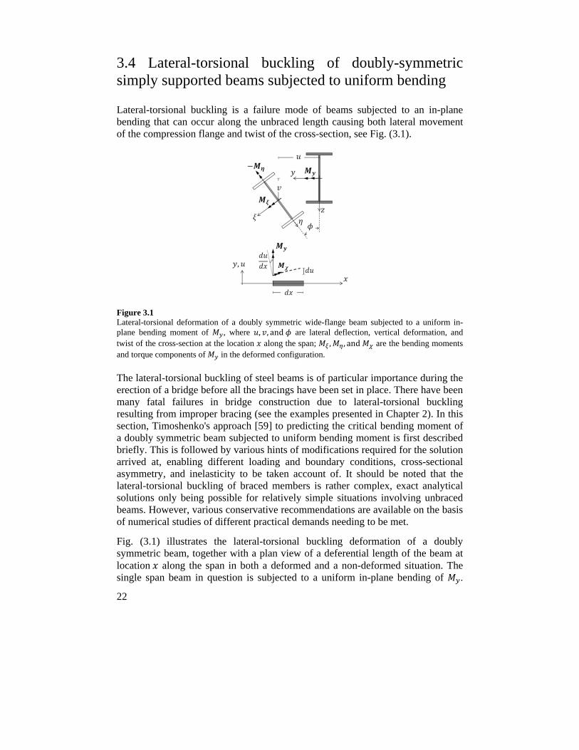
Lateral-torsional buckling is a failure mode of beams subjected to an in-plane bending that can occur along the unbraced length causing both lateral movement of the compression flange and twist of the cross-section, see Fig. (3.1).
Figure 3.1 Lateral-torsional deformation of a doubly symmetric wide-flange beam subjected to a uniform in-plane bending moment of , where , , and are lateral deflection, vertical deformation, and twist of the cross-section at the location along the span; , , and are the bending moments and torque components of in the deformed configuration.
The lateral-torsional buckling of steel beams is of particular importance during the erection of a bridge before all the bracings have been set in place. There have been many fatal failures in bridge construction due to lateral-torsional buckling resulting from improper bracing (see the examples presented in Chapter 2). In this section, Timoshenko's approach [59] to predicting the critical bending moment of a doubly symmetric beam subjected to uniform bending moment is first described briefly. This is followed by various hints of modifications required for the solution arrived at, enabling different loading and boundary conditions, cross-sectional asymmetry, and inelasticity to be taken account of. It should be noted that the lateral-torsional buckling of braced members is rather complex, exact analytical solutions only being possible for relatively simple situations involving unbraced beams. However, various conservative recommendations are available on the basis of numerical studies of different practical demands needing to be met.
Fig. (3.1) illustrates the lateral-torsional buckling deformation of a doubly symmetric beam, together with a plan view of a deferential length of the beam at location along the span in both a deformed and a non-deformed situation. The single span beam in question is subjected to a uniform in-plane bending of .
23
The out-of-plane deformations are represented by centroid lateral and vertical movements of and , and a cross-sectional twist of ∅. The beam is free to warp and is restrained against twist at both ends. The material involved is elastic, small deformation theory being applied ( ∅ ∅and ∅ 1 , it is being assumed that local buckling does not occur in any part of the cross-section. In Fig. (3.1), the bending moments and torsional components of that are applied to the deformed cross-section are as follows:
; ∅; 3.3
An equilibrium of the external and internal forces requires that the followings apply [59, 60]:
3.4
3.5
3.6
Only Eqs. (3.5)-(3.6) involve lateral-torsional deformations. Substituting from Eq. (3.5) into the equation obtained through a differentiation of Eq. (3.6) with respect to results in the following differential equation:
0 3.7
Substituting the corresponding boundary conditions (where at both ends the lateral and vertical deflections, the twist, and the bending moment about axis are set to a value of zero) into the solution of Eq. (3.7) results in the following equation for the critical moment value:
, , ∙ 1 3.8
3.5 Modifications required in the basic approach to the critical bending moment value
The basic Timoshenko's approach presented here as Eq. (3.8) was derived on the basis of the following assumptions: the beam has a doubly-symmetric cross-section, simply supported boundary conditions, and is subjected to a uniform
24
bending moment. A closed-form solution is rather difficult or even impossible to obtain for most of the other boundary and loading conditions that exist in practice. For limited cases, a number of approximate modifications involving mainly numerical studies have been suggested in the literature. Major concerns regarding possible alternative conditions other than those assumed in derivation of Eq. (3.8), are explained in the subsections that follow.
3.5.1 Effects of different boundary conditions
A similar mathematical process such as that presented in Section (3.4) can be carried out so as to obtain predictions of the critical bending moment for different boundary conditions other than the warping-free and twist-restrained situations assumed in the derivation of Eq. (3.8). An approximate conservative solution based on an extension of the effective length method is given in Eq. (3.9) [61]. This equation can be used as a general solution for different boundary conditions. Under both-end fixed, both-end free, or one-end-free and the-other-end-fixed conditions, the and values involved would be equal to 1.0, 0.5, or 0.7 [61].
, , ∙ 1 3.9
3.5.2 Effects of different loading conditions
A variety of loading configurations for a beam prone to lateral-torsional buckling are possible to occur in practice. Transverse loads applied to the top or bottom flange of the beam shown in Section (3.4), decrease or increase, respectively, the critical moment value [4]. Unfortunately, for most practical loading conditions, employing an exact analytical solution for determining the critical moment value is either impossible or cumbersome. A number of studies (e.g. [62-65]) have presented expressions that can modify Timoshenko's basic equation so as to account for the benefits of variable bending moment distributions other than the uniform bending moment assumed in derivation of Eq. (3.8). Such recommendations result in critical moment values that are based on conservative fits to the data involved. For example, the following factor, based on a use of a so-called three-quarter-point-moment method (see e.g. [4, 66]) is recommended by AISC [67]:
12.52.5 3 4 3
3.10
25
In Eq. (3.10), is the absolute value of the maximum in-plane bending moment in the unbraced segment, and , . . . , are the absolute in-plane bending moment values at the quarter, at the center, and at the three-quarter points of the unbraced segment.
Loads applied above shear center destabilize and those below stabilize the beam as lateral-torsional buckling develops. To determine the load height effects when transverse loading is applied to the cross-section at some particular height, Eq. (3.10) needs to be multiplied by a 1.4 / factor [4], being the location of the load that is applied with respect to the midheight of the cross-section and is positive for the values below the midheight of the cross-section. Although the load-height effect decreases as the length of a member increases [68], the modification factor mentioned above provides an upper-bound value for the beam spans typically employed. Eq. (3.10) needs to also be multiplied to a modification factor of 0.5 2 , / when the beam is subjected to a double-curvature bending along an unbraced segment; where , is the moment of inertia of the top flange with respect to the weak axis of the cross-section.
As the result of numerical studies that were performed, Yura et al. [37] showed that for twin-I girders that were inter-braced by means of typical cross-bracings, the load height had only minor effects on the critical load values. Park et al. [29] also developed various modification factors to account for the effects of lateral restraints. Those critical moment modification factors have been developed for single beams in connection with numerical studies. While for cases encountered in practice in which a number of beams involved are inter-connected by means of cross-bracings, the results arrived at through such various modification factors might not be truly justified.
3.5.3 Effects of lateral restraints (Paper II)
Fig. (3.2 a) illustrates a situation in which a simply supported beam is braced laterally at one-third and two-thirds of the span locations. The side segments are subjected to considerably lesser in-plane bending than the central segment, and acting as restraining members at both ends of the central segment. Such a case was studied by Galambos [45], who calculated the effective buckling length of the central segment as being 0.83 .
Another case of the restraining effects of the side segments on the effective buckling length of the compression flange of the inner segment is that illustrated in Fig. (3.2 b). There the side segments, having shorter unbraced lengths provide restraints on lateral rotation at both ends of the central segment. This case is a part of an investigation reported by the author in paper II [69]. Although the primary concern of paper II is the applicability of a simplified method in prediction of the critical moment value of laterally braced beams, the study also examines the
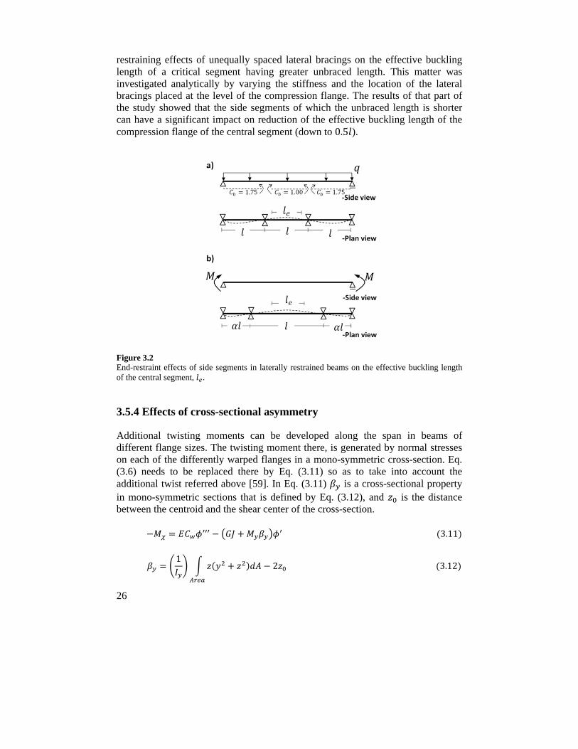
26
restraining effects of unequally spaced lateral bracings on the effective buckling length of a critical segment having greater unbraced length. This matter was investigated analytically by varying the stiffness and the location of the lateral bracings placed at the level of the compression flange. The results of that part of the study showed that the side segments of which the unbraced length is shorter can have a significant impact on reduction of the effective buckling length of the compression flange of the central segment (down to 0.5 ).
Figure 3.2 End-restraint effects of side segments in laterally restrained beams on the effective buckling length of the central segment, .
3.5.4 Effects of cross-sectional asymmetry
Additional twisting moments can be developed along the span in beams of different flange sizes. The twisting moment there, is generated by normal stresses on each of the differently warped flanges in a mono-symmetric cross-section. Eq. (3.6) needs to be replaced there by Eq. (3.11) so as to take into account the additional twist referred above [59]. In Eq. (3.11) is a cross-sectional property in mono-symmetric sections that is defined by Eq. (3.12), and is the distance between the centroid and the shear center of the cross-section.
3.11
12
3.12
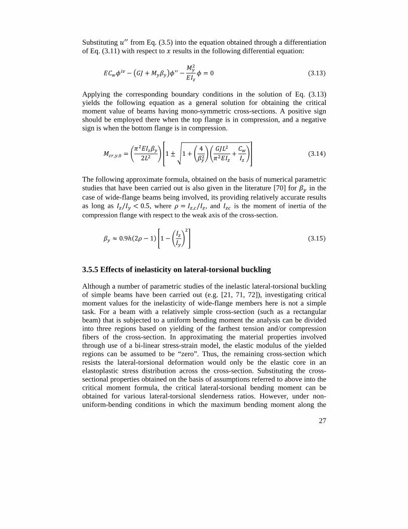
27
Substituting from Eq. (3.5) into the equation obtained through a differentiation of Eq. (3.11) with respect to results in the following differential equation:
0 3.13
Applying the corresponding boundary conditions in the solution of Eq. (3.13) yields the following equation as a general solution for obtaining the critical moment value of beams having mono-symmetric cross-sections. A positive sign should be employed there when the top flange is in compression, and a negative sign is when the bottom flange is in compression.
, , 21 1
4 3.14
The following approximate formula, obtained on the basis of numerical parametric studies that have been carried out is also given in the literature [70] for in the case of wide-flange beams being involved, its providing relatively accurate results as long as / 0.5, where , / , and is the moment of inertia of the compression flange with respect to the weak axis of the cross-section.
0.9 2 1 1 3.15
3.5.5 Effects of inelasticity on lateral-torsional buckling
Although a number of parametric studies of the inelastic lateral-torsional buckling of simple beams have been carried out (e.g. [21, 71, 72]), investigating critical moment values for the inelasticity of wide-flange members here is not a simple task. For a beam with a relatively simple cross-section (such as a rectangular beam) that is subjected to a uniform bending moment the analysis can be divided into three regions based on yielding of the farthest tension and/or compression fibers of the cross-section. In approximating the material properties involved through use of a bi-linear stress-strain model, the elastic modulus of the yielded regions can be assumed to be “zero”. Thus, the remaining cross-section which resists the lateral-torsional deformation would only be the elastic core in an elastoplastic stress distribution across the cross-section. Substituting the cross-sectional properties obtained on the basis of assumptions referred to above into the critical moment formula, the critical lateral-torsional bending moment can be obtained for various lateral-torsional slenderness ratios. However, under non-uniform-bending conditions in which the maximum bending moment along the
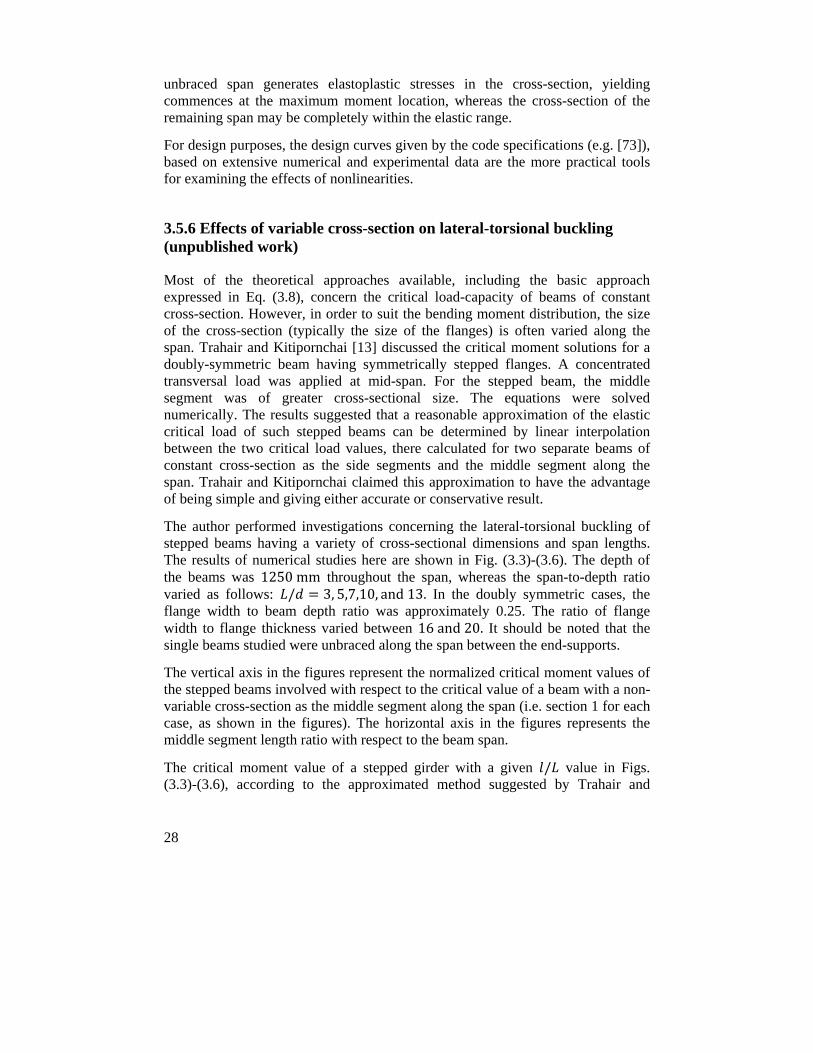
28
unbraced span generates elastoplastic stresses in the cross-section, yielding commences at the maximum moment location, whereas the cross-section of the remaining span may be completely within the elastic range.
For design purposes, the design curves given by the code specifications (e.g. [73]), based on extensive numerical and experimental data are the more practical tools for examining the effects of nonlinearities.
3.5.6 Effects of variable cross-section on lateral-torsional buckling (unpublished work)
Most of the theoretical approaches available, including the basic approach expressed in Eq. (3.8), concern the critical load-capacity of beams of constant cross-section. However, in order to suit the bending moment distribution, the size of the cross-section (typically the size of the flanges) is often varied along the span. Trahair and Kitipornchai [13] discussed the critical moment solutions for a doubly-symmetric beam having symmetrically stepped flanges. A concentrated transversal load was applied at mid-span. For the stepped beam, the middle segment was of greater cross-sectional size. The equations were solved numerically. The results suggested that a reasonable approximation of the elastic critical load of such stepped beams can be determined by linear interpolation between the two critical load values, there calculated for two separate beams of constant cross-section as the side segments and the middle segment along the span. Trahair and Kitipornchai claimed this approximation to have the advantage of being simple and giving either accurate or conservative result.
The author performed investigations concerning the lateral-torsional buckling of stepped beams having a variety of cross-sectional dimensions and span lengths. The results of numerical studies here are shown in Fig. (3.3)-(3.6). The depth of the beams was 1250mm throughout the span, whereas the span-to-depth ratio varied as follows: / 3, 5,7,10, and13. In the doubly symmetric cases, the flange width to beam depth ratio was approximately 0.25. The ratio of flange width to flange thickness varied between 16and20. It should be noted that the single beams studied were unbraced along the span between the end-supports.
The vertical axis in the figures represent the normalized critical moment values of the stepped beams involved with respect to the critical value of a beam with a non-variable cross-section as the middle segment along the span (i.e. section 1 for each case, as shown in the figures). The horizontal axis in the figures represents the middle segment length ratio with respect to the beam span.
The critical moment value of a stepped girder with a given / value in Figs. (3.3)-(3.6), according to the approximated method suggested by Trahair and
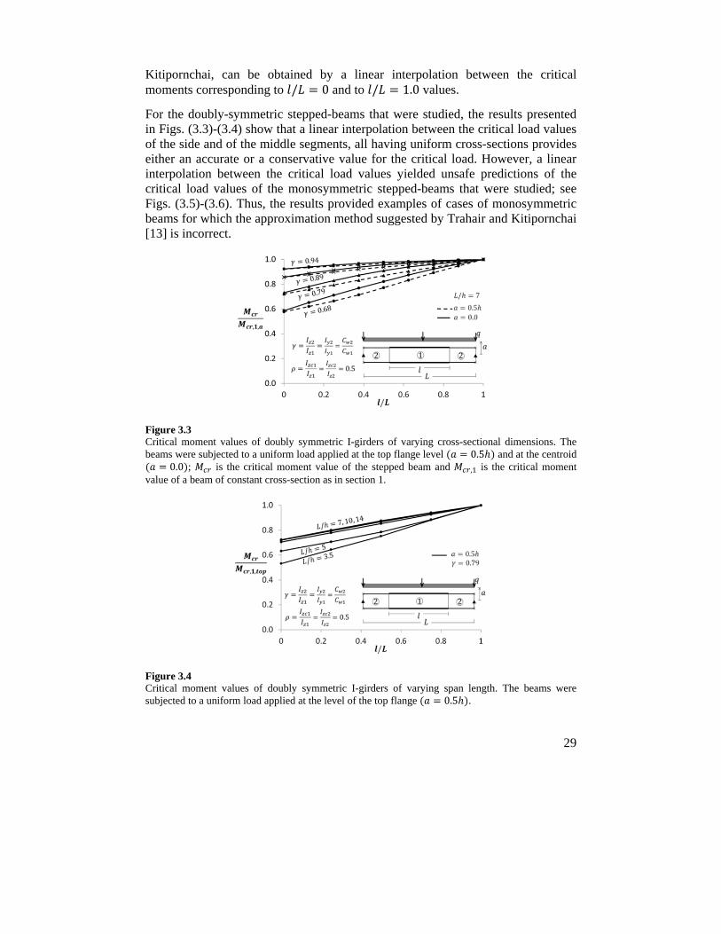
29
Kitipornchai, can be obtained by a linear interpolation between the critical moments corresponding to / 0 and to / 1.0 values.
For the doubly-symmetric stepped-beams that were studied, the results presented in Figs. (3.3)-(3.4) show that a linear interpolation between the critical load values of the side and of the middle segments, all having uniform cross-sections provides either an accurate or a conservative value for the critical load. However, a linear interpolation between the critical load values yielded unsafe predictions of the critical load values of the monosymmetric stepped-beams that were studied; see Figs. (3.5)-(3.6). Thus, the results provided examples of cases of monosymmetric beams for which the approximation method suggested by Trahair and Kitipornchai [13] is incorrect.
Figure 3.3 Critical moment values of doubly symmetric I-girders of varying cross-sectional dimensions. The beams were subjected to a uniform load applied at the top flange level 0.5 and at the centroid
0.0 ; is the critical moment value of the stepped beam and , is the critical moment value of a beam of constant cross-section as in section 1.
Figure 3.4 Critical moment values of doubly symmetric I-girders of varying span length. The beams were subjected to a uniform load applied at the level of the top flange 0.5 .
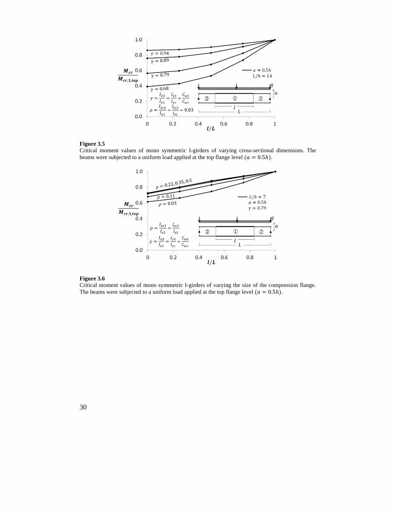
30
Figure 3.5 Critical moment values of mono symmetric I-girders of varying cross-sectional dimensions. The beams were subjected to a uniform load applied at the top flange level 0.5 .
Figure 3.6 Critical moment values of mono symmetric I-girders of varying the size of the compression flange. The beams were subjected to a uniform load applied at the top flange level 0.5 .
31
4 Fundamentals of beam bracing
Bracings are the structural members normally needed to sustain the stability of load-bearing members in order to reach a desired load-carrying capacity in addition to the function they have of resisting the horizontal loads. This takes place by means of their controlling the out-of-plane deformations of the main members. The bracings should be adequate in terms of both stiffness and strength. Since lateral-torsional buckling involves two types of deformation, i.e. lateral movement and twist, bracings are normally studied in terms of the two separate categories of bracing, lateral and torsional, that control mainly the lateral deformation of compression flanges and the relative displacement of the top and bottom flanges, respectively. However, lateral bracings can also prevent twisting of a beam cross-section if they are located at a distance from the shear center of the cross-section. Bracings of these two types can be placed either at discrete nodal points or continuously along the span involved. In beam analyses, lateral bracings are normally modeled as linear translational springs, and torsional bracings as rotational springs. The present chapter introduces the fundamentals of beam bracing and applications of it within the bridge sector. A brief discussion of “the columns having elastic supports” is also provided at the end of this chapter, since this model is currently used by design engineers (see Appendix III) for estimating the lateral-torsional buckling of the bottom flange of continuous composite girders braced by means of cross-bracings.
4.1 Introduction
Bracings are generally classified in terms of four separate categories based on their function they fulfil:
- Discrete or nodal bracing, which controls the corresponding movements of the braced member at the attachment point; intermediate and support cross-beams/-diaphragms/or -frames in bridge application are examples of nodal-torsional bracings.
- Continuous bracing, which resists lateral movement of the compression flange or twisting of a beam cross-section along the braced span; reinforced concrete decks are examples of the bracing of the continuous type.
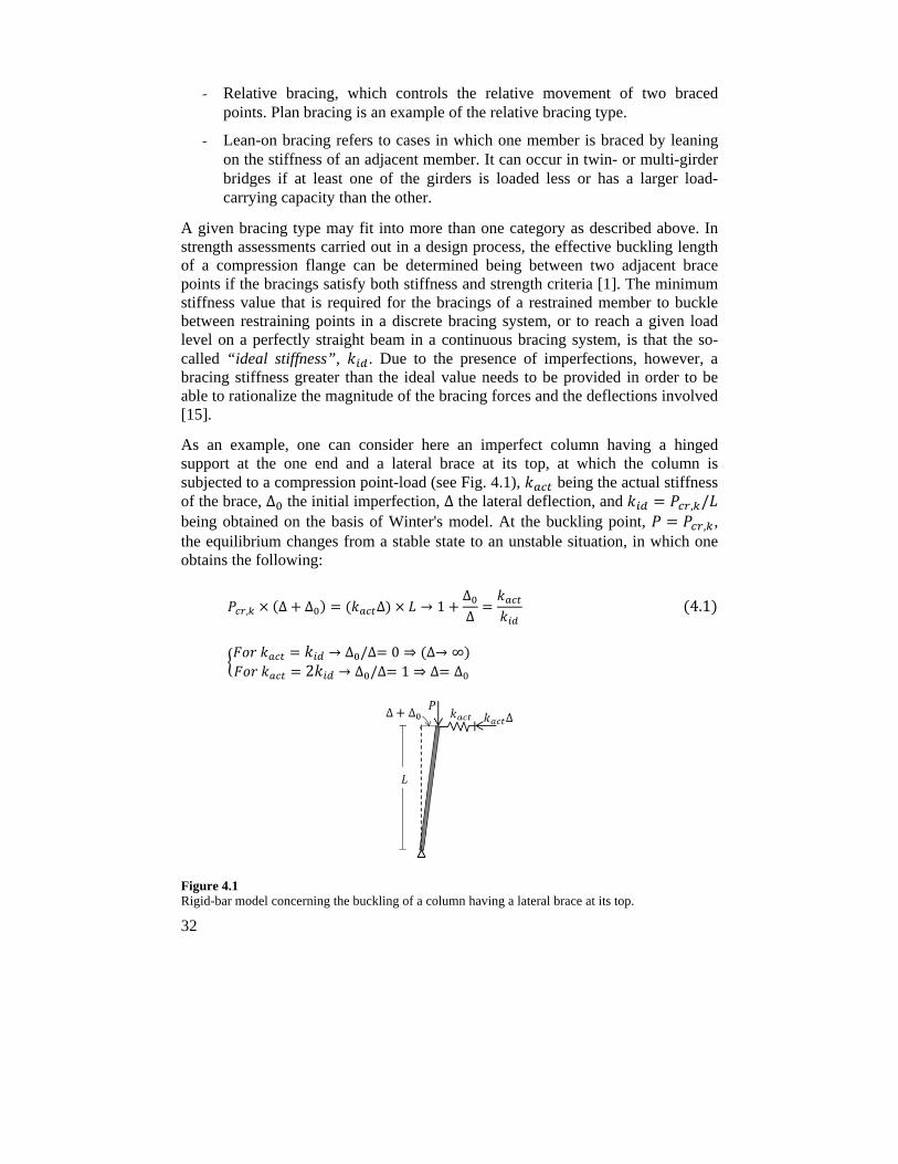
32
- Relative bracing, which controls the relative movement of two braced points. Plan bracing is an example of the relative bracing type.
- Lean-on bracing refers to cases in which one member is braced by leaning on the stiffness of an adjacent member. It can occur in twin- or multi-girder bridges if at least one of the girders is loaded less or has a larger load-carrying capacity than the other.
A given bracing type may fit into more than one category as described above. In strength assessments carried out in a design process, the effective buckling length of a compression flange can be determined being between two adjacent brace points if the bracings satisfy both stiffness and strength criteria [1]. The minimum stiffness value that is required for the bracings of a restrained member to buckle between restraining points in a discrete bracing system, or to reach a given load level on a perfectly straight beam in a continuous bracing system, is that the so-called “ideal stiffness”, . Due to the presence of imperfections, however, a bracing stiffness greater than the ideal value needs to be provided in order to be able to rationalize the magnitude of the bracing forces and the deflections involved [15].
As an example, one can consider here an imperfect column having a hinged support at the one end and a lateral brace at its top, at which the column is subjected to a compression point-load (see Fig. 4.1), being the actual stiffness of the brace, ∆ the initial imperfection, ∆ the lateral deflection, and , / being obtained on the basis of Winter's model. At the buckling point, , , the equilibrium changes from a stable state to an unstable situation, in which one obtains the following:
, ∆ ∆ ∆ → 1∆∆
4.1
→ ∆ /∆ 0 ⇒ ∆→ ∞ 2 → ∆ /∆ 1 ⇒ ∆ ∆
Figure 4.1 Rigid-bar model concerning the buckling of a column having a lateral brace at its top.
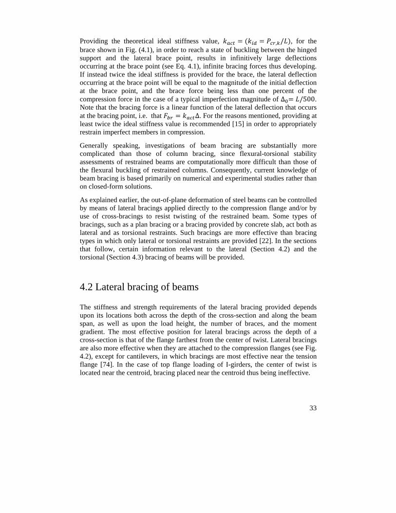
33
Providing the theoretical ideal stiffness value, , / , for the brace shown in Fig. (4.1), in order to reach a state of buckling between the hinged support and the lateral brace point, results in infinitively large deflections occurring at the brace point (see Eq. 4.1), infinite bracing forces thus developing. If instead twice the ideal stiffness is provided for the brace, the lateral deflection occurring at the brace point will be equal to the magnitude of the initial deflection at the brace point, and the brace force being less than one percent of the compression force in the case of a typical imperfection magnitude of ∆ /500. Note that the bracing force is a linear function of the lateral deflection that occurs at the bracing point, i.e. that ∆. For the reasons mentioned, providing at least twice the ideal stiffness value is recommended [15] in order to appropriately restrain imperfect members in compression.
Generally speaking, investigations of beam bracing are substantially more complicated than those of column bracing, since flexural-torsional stability assessments of restrained beams are computationally more difficult than those of the flexural buckling of restrained columns. Consequently, current knowledge of beam bracing is based primarily on numerical and experimental studies rather than on closed-form solutions.
As explained earlier, the out-of-plane deformation of steel beams can be controlled by means of lateral bracings applied directly to the compression flange and/or by use of cross-bracings to resist twisting of the restrained beam. Some types of bracings, such as a plan bracing or a bracing provided by concrete slab, act both as lateral and as torsional restraints. Such bracings are more effective than bracing types in which only lateral or torsional restraints are provided [22]. In the sections that follow, certain information relevant to the lateral (Section 4.2) and the torsional (Section 4.3) bracing of beams will be provided.
4.2 Lateral bracing of beams
The stiffness and strength requirements of the lateral bracing provided depends upon its locations both across the depth of the cross-section and along the beam span, as well as upon the load height, the number of braces, and the moment gradient. The most effective position for lateral bracings across the depth of a cross-section is that of the flange farthest from the center of twist. Lateral bracings are also more effective when they are attached to the compression flanges (see Fig. 4.2), except for cantilevers, in which bracings are most effective near the tension flange [74]. In the case of top flange loading of I-girders, the center of twist is located near the centroid, bracing placed near the centroid thus being ineffective.
34
Figure 4.2 An illustration of load-height and bracing location effects on the critical moment values of laterally braced beams, , being the critical moment value of the beam having a lateral brace at mid-span in differenet configurations (1),…, (4), as shown, and , being the critical moment value of the unbraced beam having a point load at the centroid of the cross-section [4].
For a beam in a reverse-curvature-bending condition along its span, lateral bracings should be provided for both of the flanges at the inflection point, so as to prevent twisting of the cross-section at this point [74]. Under such particular circumstances, a lateral bracing of only the top flange would scarcely be effective.
4.3 Torsional bracing of beams
Torsional bracings are designed to resist the twisting of individual beams (i.e. a lateral movement relative to each other of the top and the bottom flanges) rather than to resist only lateral movements of a compression flange. When cross-bracings are utilized in steel bridge application, this occurs through its limiting the relative displacements of the top and the bottom flanges of adjacent girders. The stiffness requirements of torsional bracings are less affected by the location of loading and bracing across the depth of the cross-section [4], i.e. torsional bracings of the top flange and of the bottom flange are about equally effective. However, cross-sectional distortion can strongly affect the effectiveness of torsional bracings. Accordingly, use of proper web-stiffeners at the site of each cross-bracing is recommended.
Fig. (4.3) illustrates the effects on the critical load value of the location of torsional bracings across the depth of a beam for different web-stiffener arrangements [74]. The most effective location of torsional bracings, such as cross-beams across the depth of a cross-section, in order for the distortion and the size of the web-stiffeners involved to be minimized, is that they be located near the
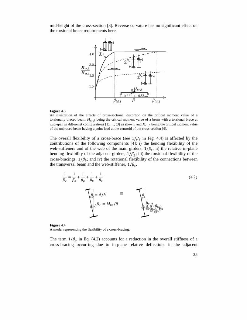
35
mid-height of the cross-section [3]. Reverse curvature has no significant effect on the torsional brace requirements here.
Figure 4.3 An illustration of the effects of cross-sectional distortion on the critical moment value of a torsionally braced beam, , being the critical moment value of a beam with a torsional brace at mid-span in differenet configurations (1),…, (3) as shown, and , being the critical moment value of the unbraced beam having a point load at the centroid of the cross-section [4].
The overall flexibility of a cross-brace (see 1/ in Fig. 4.4) is affected by the contributions of the following components [4]: i) the bending flexibility of the web-stiffeners and of the web of the main girders, 1/ ; ii) the relative in-plane bending flexibility of the adjacent girders, 1/ ; iii) the torsional flexibility of the cross-bracings, 1/ ; and iv) the rotational flexibility of the connections between the transversal beam and the web-stiffener, 1/ .
1 1 1 1 1 4.2
Figure 4.4 A model representing the flexibility of a cross-bracing.
The term 1/ in Eq. (4.2) accounts for a reduction in the overall stiffness of a cross-bracing occurring due to in-plane relative deflections in the adjacent
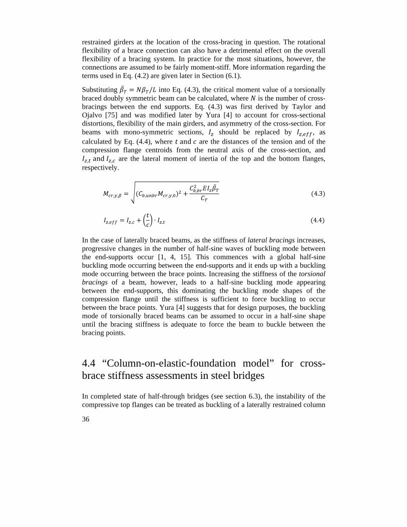
36
restrained girders at the location of the cross-bracing in question. The rotational flexibility of a brace connection can also have a detrimental effect on the overall flexibility of a bracing system. In practice for the most situations, however, the connections are assumed to be fairly moment-stiff. More information regarding the terms used in Eq. (4.2) are given later in Section (6.1).
Substituting / into Eq. (4.3), the critical moment value of a torsionally braced doubly symmetric beam can be calculated, where is the number of cross-bracings between the end supports. Eq. (4.3) was first derived by Taylor and Ojalvo [75] and was modified later by Yura [4] to account for cross-sectional distortions, flexibility of the main girders, and asymmetry of the cross-section. For beams with mono-symmetric sections, should be replaced by , , as calculated by Eq. (4.4), where and are the distances of the tension and of the compression flange centroids from the neutral axis of the cross-section, and , and , are the lateral moment of inertia of the top and the bottom flanges,
respectively.
, , , , ,,
4.3
, , ∙ , 4.4
In the case of laterally braced beams, as the stiffness of lateral bracings increases, progressive changes in the number of half-sine waves of buckling mode between the end-supports occur [1, 4, 15]. This commences with a global half-sine buckling mode occurring between the end-supports and it ends up with a buckling mode occurring between the brace points. Increasing the stiffness of the torsional bracings of a beam, however, leads to a half-sine buckling mode appearing between the end-supports, this dominating the buckling mode shapes of the compression flange until the stiffness is sufficient to force buckling to occur between the brace points. Yura [4] suggests that for design purposes, the buckling mode of torsionally braced beams can be assumed to occur in a half-sine shape until the bracing stiffness is adequate to force the beam to buckle between the bracing points.
4.4 “Column-on-elastic-foundation model” for cross-brace stiffness assessments in steel bridges
In completed state of half-through bridges (see section 6.3), the instability of the compressive top flanges can be treated as buckling of a laterally restrained column
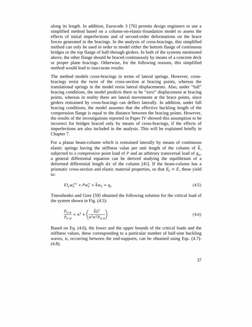
37
along its length. In addition, Eurocode 3 [76] permits design engineers to use a simplified method based on a column-on-elastic-foundation model to assess the effects of initial imperfections and of second-order deformations on the brace forces generated in the bracings. In the analysis of cross-bracings, this simplified method can only be used in order to model either the bottom flange of continuous bridges or the top flange of half-through girders. In both of the systems mentioned above, the other flange should be braced continuously by means of a concrete deck or proper plane bracings. Otherwise, for the following reasons, this simplified method would lead to inaccurate results:
The method models cross-bracings in terms of lateral springs. However, cross-bracings resist the twist of the cross-section at bracing points, whereas the translational springs in the model resist lateral displacements. Also, under “full” bracing conditions, the model predicts there to be “zero” displacement at bracing points, whereas in reality there are lateral movements at the brace points, since girders restrained by cross-bracings can deflect laterally. In addition, under full bracing conditions, the model assumes that the effective buckling length of the compression flange is equal to the distance between the bracing points. However, the results of the investigations reported in Paper IV showed this assumption to be incorrect for bridges braced only by means of cross-bracings, if the effects of imperfections are also included in the analysis. This will be explained briefly in Chapter 7.
For a planar beam-column which is restrained laterally by means of continuous elastic springs having the stiffness value per unit length of the column of , subjected to a compressive point load of and an arbitrary transversal load of , a general differential equation can be derived studying the equilibrium of a deformed differential length of the column [45]. If the beam-column has a prismatic cross-section and elastic material properties, so that , these yield to:
4.5
Timoshenko and Gere [59] obtained the following solution for the critical load of the system shown in Fig. (4.5):
,
, , 4.6
Based on Eq. (4.6), the lower and the upper bounds of the critical loads and the stiffness values, these corresponding to a particular number of half-sine buckling waves, , occurring between the end-supports, can be obtained using Eqs. (4.7)-(4.8).
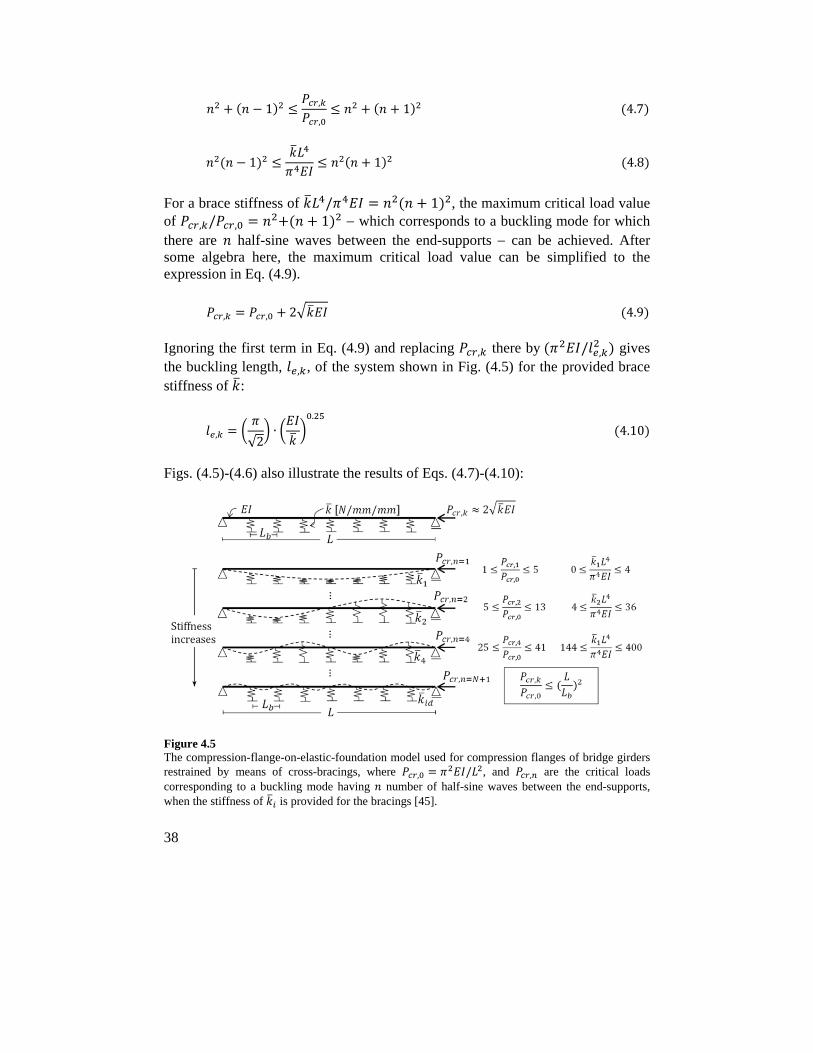
38
1 ,
,1 4.7
1 1 4.8
For a brace stiffness of / 1 , the maximum critical load value of , / , 1 which corresponds to a buckling mode for which there are half-sine waves between the end-supports can be achieved. After some algebra here, the maximum critical load value can be simplified to the expression in Eq. (4.9).
, , 2 4.9
Ignoring the first term in Eq. (4.9) and replacing , there by / , gives the buckling length, , , of the system shown in Fig. (4.5) for the provided brace stiffness of :
,√2
∙.
4.10
Figs. (4.5)-(4.6) also illustrate the results of Eqs. (4.7)-(4.10):
Figure 4.5 The compression-flange-on-elastic-foundation model used for compression flanges of bridge girders restrained by means of cross-bracings, where , / , and , are the critical loads corresponding to a buckling mode having number of half-sine waves between the end-supports, when the stiffness of is provided for the bracings [45].
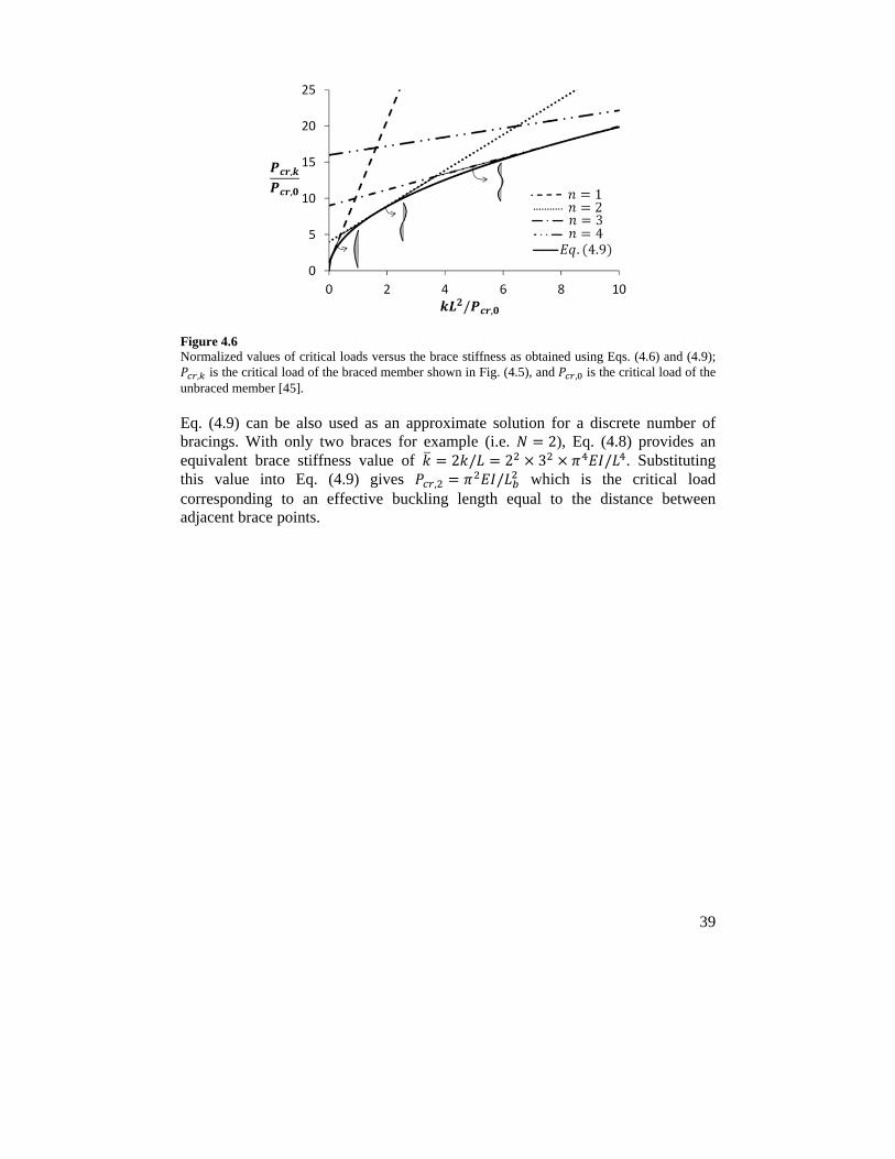
39
Figure 4.6 Normalized values of critical loads versus the brace stiffness as obtained using Eqs. (4.6) and (4.9);
, is the critical load of the braced member shown in Fig. (4.5), and , is the critical load of the unbraced member [45].
Eq. (4.9) can be also used as an approximate solution for a discrete number of bracings. With only two braces for example (i.e. 2), Eq. (4.8) provides an equivalent brace stiffness value of 2 / 2 3 / . Substituting this value into Eq. (4.9) gives , / which is the critical load corresponding to an effective buckling length equal to the distance between adjacent brace points.

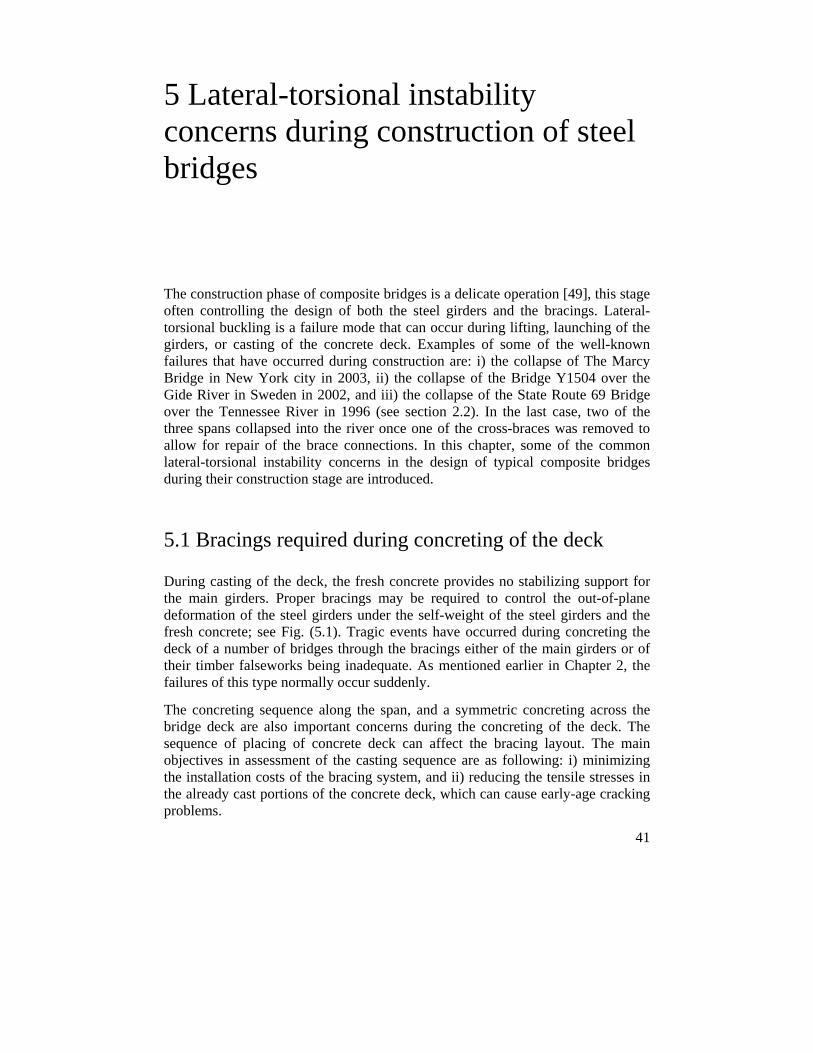
41
5 Lateral-torsional instability concerns during construction of steel bridges
The construction phase of composite bridges is a delicate operation [49], this stage often controlling the design of both the steel girders and the bracings. Lateral-torsional buckling is a failure mode that can occur during lifting, launching of the girders, or casting of the concrete deck. Examples of some of the well-known failures that have occurred during construction are: i) the collapse of The Marcy Bridge in New York city in 2003, ii) the collapse of the Bridge Y1504 over the Gide River in Sweden in 2002, and iii) the collapse of the State Route 69 Bridge over the Tennessee River in 1996 (see section 2.2). In the last case, two of the three spans collapsed into the river once one of the cross-braces was removed to allow for repair of the brace connections. In this chapter, some of the common lateral-torsional instability concerns in the design of typical composite bridges during their construction stage are introduced.
5.1 Bracings required during concreting of the deck
During casting of the deck, the fresh concrete provides no stabilizing support for the main girders. Proper bracings may be required to control the out-of-plane deformation of the steel girders under the self-weight of the steel girders and the fresh concrete; see Fig. (5.1). Tragic events have occurred during concreting the deck of a number of bridges through the bracings either of the main girders or of their timber falseworks being inadequate. As mentioned earlier in Chapter 2, the failures of this type normally occur suddenly.
The concreting sequence along the span, and a symmetric concreting across the bridge deck are also important concerns during the concreting of the deck. The sequence of placing of concrete deck can affect the bracing layout. The main objectives in assessment of the casting sequence are as following: i) minimizing the installation costs of the bracing system, and ii) reducing the tensile stresses in the already cast portions of the concrete deck, which can cause early-age cracking problems.
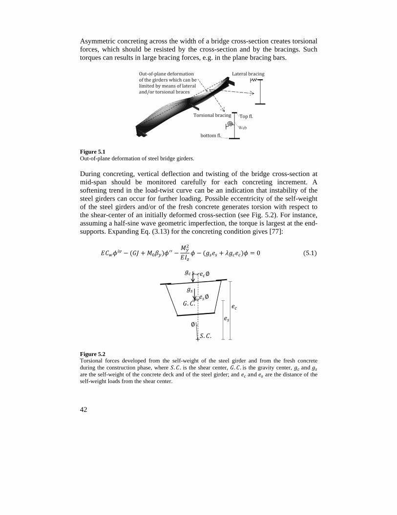
42
Asymmetric concreting across the width of a bridge cross-section creates torsional forces, which should be resisted by the cross-section and by the bracings. Such torques can results in large bracing forces, e.g. in the plane bracing bars.
Figure 5.1 Out-of-plane deformation of steel bridge girders.
During concreting, vertical deflection and twisting of the bridge cross-section at mid-span should be monitored carefully for each concreting increment. A softening trend in the load-twist curve can be an indication that instability of the steel girders can occur for further loading. Possible eccentricity of the self-weight of the steel girders and/or of the fresh concrete generates torsion with respect to the shear-center of an initially deformed cross-section (see Fig. 5.2). For instance, assuming a half-sine wave geometric imperfection, the torque is largest at the end-supports. Expanding Eq. (3.13) for the concreting condition gives [77]:
0 5.1
Figure 5.2 Torsional forces developed from the self-weight of the steel girder and from the fresh concrete during the construction phase, where . . is the shear center, . .is the gravity center, and are the self-weight of the concrete deck and of the steel girder; and and are the distance of the self-weight loads from the shear center.
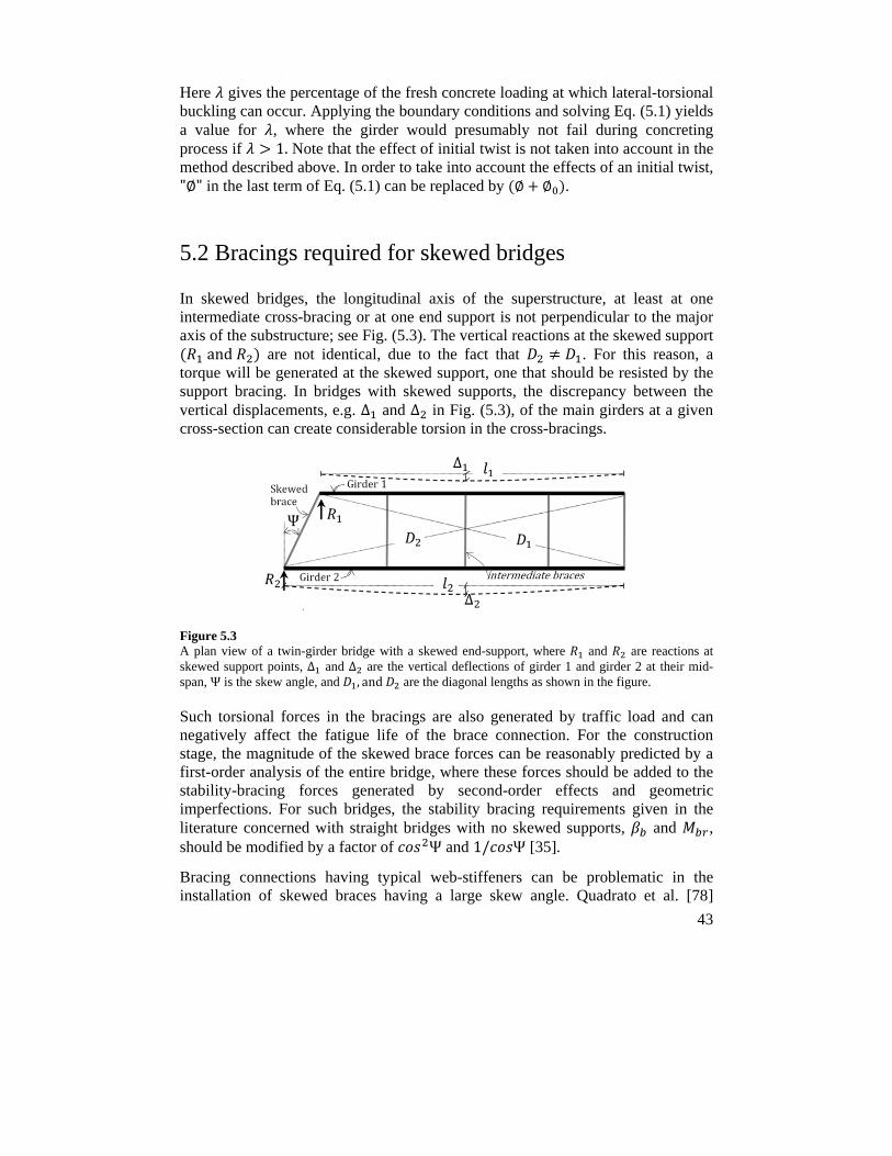
43
Here gives the percentage of the fresh concrete loading at which lateral-torsional buckling can occur. Applying the boundary conditions and solving Eq. (5.1) yields a value for , where the girder would presumably not fail during concreting process if 1. Note that the effect of initial twist is not taken into account in the method described above. In order to take into account the effects of an initial twist, "∅" in the last term of Eq. (5.1) can be replaced by ∅ ∅ .
5.2 Bracings required for skewed bridges
In skewed bridges, the longitudinal axis of the superstructure, at least at one intermediate cross-bracing or at one end support is not perpendicular to the major axis of the substructure; see Fig. (5.3). The vertical reactions at the skewed support
and are not identical, due to the fact that . For this reason, a torque will be generated at the skewed support, one that should be resisted by the support bracing. In bridges with skewed supports, the discrepancy between the vertical displacements, e.g. ∆ and ∆ in Fig. (5.3), of the main girders at a given cross-section can create considerable torsion in the cross-bracings.
Figure 5.3 A plan view of a twin-girder bridge with a skewed end-support, where and are reactions at skewed support points, ∆ and ∆ are the vertical deflections of girder 1 and girder 2 at their mid-span, Ψ is the skew angle, and , and are the diagonal lengths as shown in the figure.
Such torsional forces in the bracings are also generated by traffic load and can negatively affect the fatigue life of the brace connection. For the construction stage, the magnitude of the skewed brace forces can be reasonably predicted by a first-order analysis of the entire bridge, where these forces should be added to the stability-bracing forces generated by second-order effects and geometric imperfections. For such bridges, the stability bracing requirements given in the literature concerned with straight bridges with no skewed supports, and , should be modified by a factor of Ψ and 1/ Ψ [35].
Bracing connections having typical web-stiffeners can be problematic in the installation of skewed braces having a large skew angle. Quadrato et al. [78]
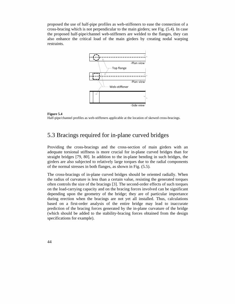
44
proposed the use of half-pipe profiles as web-stiffeners to ease the connection of a cross-bracing which is not perpendicular to the main girders; see Fig. (5.4). In case the proposed half-pipe/channel web-stiffeners are welded to the flanges, they can also enhance the critical load of the main girders by creating nodal warping restraints.
Figure 5.4 Half-pipe/channel profiles as web-stiffeners applicable at the location of skewed cross-bracings.
5.3 Bracings required for in-plane curved bridges
Providing the cross-bracings and the cross-section of main girders with an adequate torsional stiffness is more crucial for in-plane curved bridges than for straight bridges [79, 80]. In addition to the in-plane bending in such bridges, the girders are also subjected to relatively large torques due to the radial components of the normal stresses in both flanges, as shown in Fig. (5.5).
The cross-bracings of in-plane curved bridges should be oriented radially. When the radius of curvature is less than a certain value, resisting the generated torques often controls the size of the bracings [3]. The second-order effects of such torques on the load-carrying capacity and on the bracing forces involved can be significant depending upon the geometry of the bridge; they are of particular importance during erection when the bracings are not yet all installed. Thus, calculations based on a first-order analysis of the entire bridge may lead to inaccurate prediction of the bracing forces generated by the in-plane curvature of the bridge (which should be added to the stability-bracing forces obtained from the design specifications for example).
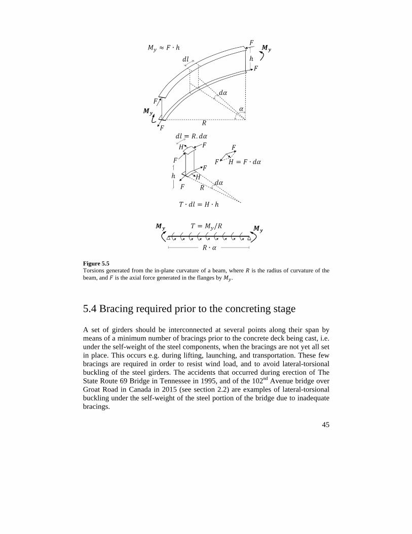
45
Figure 5.5 Torsions generated from the in-plane curvature of a beam, where is the radius of curvature of the beam, and is the axial force generated in the flanges by .
5.4 Bracing required prior to the concreting stage
A set of girders should be interconnected at several points along their span by means of a minimum number of bracings prior to the concrete deck being cast, i.e. under the self-weight of the steel components, when the bracings are not yet all set in place. This occurs e.g. during lifting, launching, and transportation. These few bracings are required in order to resist wind load, and to avoid lateral-torsional buckling of the steel girders. The accidents that occurred during erection of The State Route 69 Bridge in Tennessee in 1995, and of the 102nd Avenue bridge over Groat Road in Canada in 2015 (see section 2.2) are examples of lateral-torsional buckling under the self-weight of the steel portion of the bridge due to inadequate bracings.
46
Field monitoring of steel bridges has also shown [81] that a proper erecting sequence, erecting the girders in pairs, providing the steel girders with sufficient lateral bracings, and providing temporary shoring towers can greatly reduce the final overall deformations of steel girders which can otherwise lead to undesirable bracing forces and stresses in the main girders.
47
6 Bracing options in steel bridges
Bracings are essential structural components in steel bridges, both during construction and service. Some bracings may also be designed to enable the transfer of loads (such as wind and eccentric live loads) between girders. Slight bracings can significantly increase the load-carrying capacity of steel girders by reducing their effective buckling length. Different types and arrangements of bracings in steel bridges are possible. Utilizing only cross-bracings may not completely prevent the steel girders from moving laterally. Plan bracings are often more efficient than cross-bracings since they resist lateral movements of the compression flanges directly. Yet, they generally conflict with formworks and/or reinforcing bars, which make the concreting process rather difficult. As a result, cross-bracings are often preferred in practice.
6.1 Intermediate cross-bracings
Fig. (6.1 a-c) shows the three most common types of the cross-bracings. The cross-beam type (see Fig. 6.1 a) is preferred for shallow bridge girders, whereas the cross-diaphragm type (see Fig. 6.1 b) is often used in bridges with trapezoidal cross-sections. The K cross-frame configuration (see Fig. 6.1 c) is utilized for relatively deep girders, and is preferred to the X or the Z cross-frame types in common practice. In cross-diaphragms, large holes of at least 450mm wide and 600mm high [82] are needed for inspection and maintenance purposes. When the top flange is restrained by means of a concrete deck or a plan bracing, the major function of the cross-diaphragms is to prevent the distortion of a cross-section.
The cross-beams can be constructed by channel profiles due to the ease of the attachments to the web-stiffeners. However, Mehri et al. [83] (i.e. Paper IV) recommended considering use of symmetric cross-sections (with respect to their weak axis) for cross-beams, since relatively large warping stresses can be generated then in the transversal beam as a result of the eccentricity of brace shear forces from the shear center of an asymmetric cross-section.
The cross-bracings of a twin I-girder bridge, for example, stabilize the top flange of the main girders in the sagging regions and the bottom flange near the intermediate supports. These bracings reduce considerably the effective buckling length of the individual girders. Also, braced girders of suitable length can be
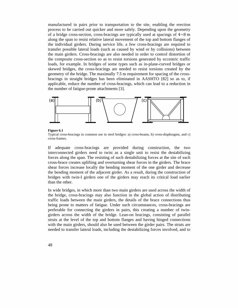
48
manufactured in pairs prior to transportation to the site, enabling the erection process to be carried out quicker and more safely. Depending upon the geometry of a bridge cross-section, cross-bracings are typically used at spacings of 4~8m along the span to resist relative lateral movement of the top and bottom flanges of the individual girders. During service life, a few cross-bracings are required to transfer possible lateral loads (such as caused by wind or by collisions) between the main girders. Cross-bracings are also needed in order to control distortion of the composite cross-section so as to resist torsions generated by eccentric traffic loads, for example. In bridges of some types such as in-plane-curved bridges or skewed bridges, the cross-bracings are needed to resist torsions created by the geometry of the bridge. The maximally 7.5m requirement for spacing of the cross-bracings in straight bridges has been eliminated in AASHTO [82] so as to, if applicable, reduce the number of cross-bracings, which can lead to a reduction in the number of fatigue-prone attachments [3].
Figure 6.1 Typical cross-bracings in common use in steel bridges: a) cross-beams, b) cross-diaphragms, and c) cross-frames.
If adequate cross-bracings are provided during construction, the two interconnected girders need to twist as a single unit to resist the destabilizing forces along the span. The resisting of such destabilizing forces at the site of each cross-brace creates uplifting and overturning shear forces in the girders. The brace shear forces increase locally the bending moment of the one girder and decrease the bending moment of the adjacent girder. As a result, during the construction of bridges with twin-I girders one of the girders may reach its critical load earlier than the other.
In wide bridges, in which more than two main girders are used across the width of the bridge, cross-bracings may also function in the global action of distributing traffic loads between the main girders, the details of the brace connections thus being prone to matters of fatigue. Under such circumstances, cross-bracings are preferable for connecting the girders in pairs, this creating a number of twin-girders across the width of the bridge. Lean-on bracings, consisting of parallel struts at the level of the top and bottom flanges and having hinged connections with the main girders, should also be used between the girder pairs. The struts are needed to transfer lateral loads, including the destabilizing forces involved, and to
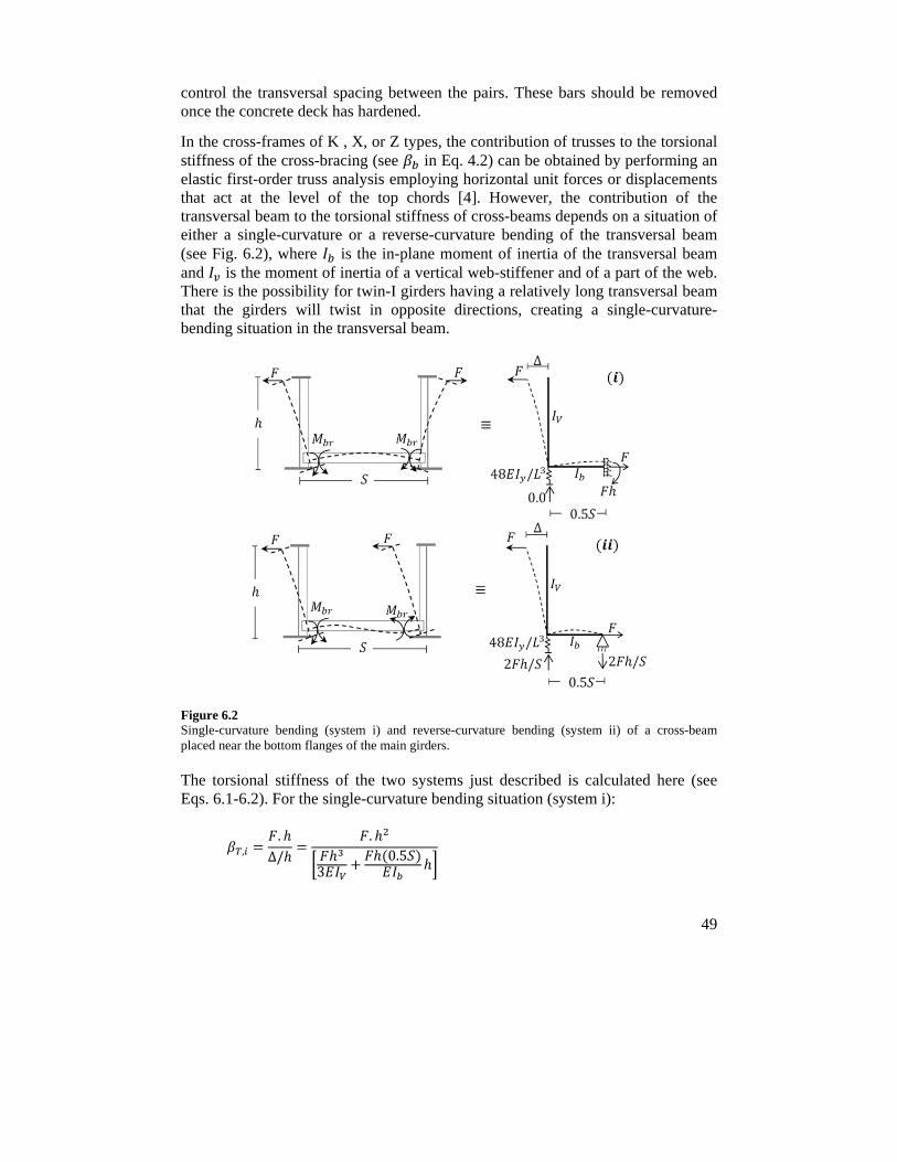
49
control the transversal spacing between the pairs. These bars should be removed once the concrete deck has hardened.
In the cross-frames of K , X, or Z types, the contribution of trusses to the torsional stiffness of the cross-bracing (see in Eq. 4.2) can be obtained by performing an elastic first-order truss analysis employing horizontal unit forces or displacements that act at the level of the top chords [4]. However, the contribution of the transversal beam to the torsional stiffness of cross-beams depends on a situation of either a single-curvature or a reverse-curvature bending of the transversal beam (see Fig. 6.2), where is the in-plane moment of inertia of the transversal beam and is the moment of inertia of a vertical web-stiffener and of a part of the web. There is the possibility for twin-I girders having a relatively long transversal beam that the girders will twist in opposite directions, creating a single-curvature-bending situation in the transversal beam.
Figure 6.2 Single-curvature bending (system i) and reverse-curvature bending (system ii) of a cross-beam placed near the bottom flanges of the main girders.
The torsional stiffness of the two systems just described is calculated here (see Eqs. 6.1-6.2). For the single-curvature bending situation (system i):
,.
∆/.
30.5
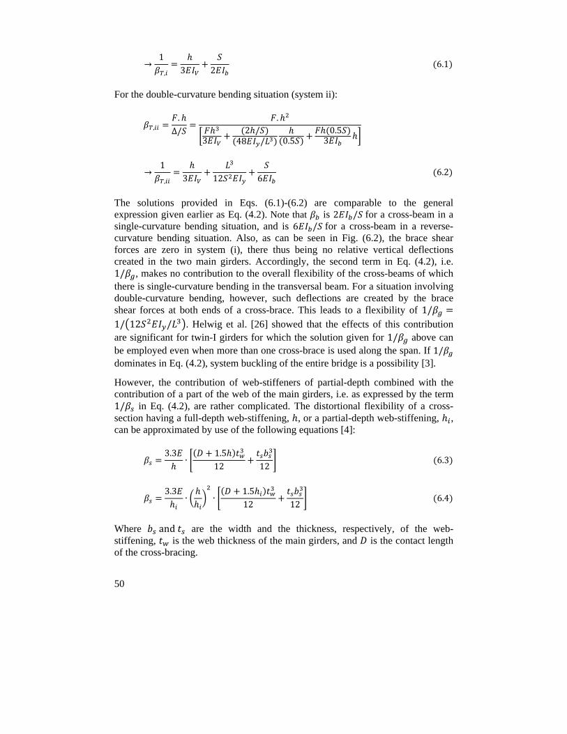
50
→1
, 3 2 6.1
For the double-curvature bending situation (system ii):
,.
∆/.
32 /
48 / 0.50.5
3
→1
, 3 12 6 6.2
The solutions provided in Eqs. (6.1)-(6.2) are comparable to the general expression given earlier as Eq. (4.2). Note that is 2 / for a cross-beam in a single-curvature bending situation, and is 6 / for a cross-beam in a reverse-curvature bending situation. Also, as can be seen in Fig. (6.2), the brace shear forces are zero in system (i), there thus being no relative vertical deflections created in the two main girders. Accordingly, the second term in Eq. (4.2), i.e. 1/ , makes no contribution to the overall flexibility of the cross-beams of which there is single-curvature bending in the transversal beam. For a situation involving double-curvature bending, however, such deflections are created by the brace shear forces at both ends of a cross-brace. This leads to a flexibility of 1/1/ 12 / . Helwig et al. [26] showed that the effects of this contribution are significant for twin-I girders for which the solution given for 1/ above can be employed even when more than one cross-brace is used along the span. If 1/ dominates in Eq. (4.2), system buckling of the entire bridge is a possibility [3].
However, the contribution of web-stiffeners of partial-depth combined with the contribution of a part of the web of the main girders, i.e. as expressed by the term 1/ in Eq. (4.2), are rather complicated. The distortional flexibility of a cross-section having a full-depth web-stiffening, , or a partial-depth web-stiffening, , can be approximated by use of the following equations [4]:
3.3∙
1.512 12
6.3
3.3∙ ∙
1.512 12
6.4
Where and are the width and the thickness, respectively, of the web-stiffening, is the web thickness of the main girders, and is the contact length of the cross-bracing.
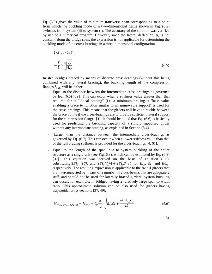
51
Eq. (6.5) gives the value of minimum transverse span corresponding to a point from which the buckling mode of a two-dimensional frame shown in Fig. (6.2) switches from system (ii) to system (i). The accuracy of the solution was verified by use of a numerical program. However, since the lateral deflection, ∆, is not constant along the bridge span, the expression is not applicable for determining the buckling mode of the cross-bracings in a three-dimensional configuration.
1/ 1/
→4
6.5
In steel-bridges braced by means of discrete cross-bracings (without this being combined with any lateral bracing), the buckling length of the compression flanges, , , will be either:
- Equal to the distance between the intermediate cross-bracings as governed by Eq. (6.6) [59]. This can occur when a stiffness value greater than that required for “full/ideal bracing” (i.e. a minimum bracing stiffness value enabling a brace to function similar to an immovable support) is used for the cross-bracings. This means that the girders will have to buckle between the brace points if the cross-bracings are to provide sufficient lateral support for the compression flanges [1]. It should be noted that Eq. (6.6) is basically used for predicting the buckling capacity of a simply supported girder without any intermediate bracing, as explained in Section (3.4).
- Larger than the distance between the intermediate cross-bracings as governed by Eq. (6.7). This can occur when a lower stiffness value than that of the full bracing stiffness is provided for the cross-bracings [4, 61].
- Equal to the length of the span, due to system buckling of the entire structure as a single unit (see Fig. 6.3), which can be estimated by Eq. (6.8) [37]. This equation was derived on the basis of equation (6.6), substituting2 , 2 , and 2 /4 2 /4 for , , and , respectively. The resulting expression is applicable to the twin-I girders that are interconnected by means of a number of cross-beams that are adequately stiff, and should not be used for laterally braced girders. System buckling can occur, for example, in bridges having a relatively large span-to-width ratio. This approximate solution can be also used for girders having trapezoidal cross-sections [37, 49].
, , , , , ∙ 6.6
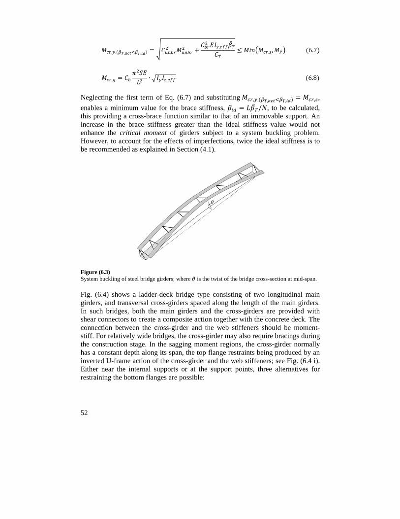
52
, , , ,
,
, , 6.7
, ∙ , 6.8
Neglecting the first term of Eq. (6.7) and substituting , , , , , ,
enables a minimum value for the brace stiffness, / , to be calculated, this providing a cross-brace function similar to that of an immovable support. An increase in the brace stiffness greater than the ideal stiffness value would not enhance the critical moment of girders subject to a system buckling problem. However, to account for the effects of imperfections, twice the ideal stiffness is to be recommended as explained in Section (4.1).
Figure (6.3) System buckling of steel bridge girders; where is the twist of the bridge cross-section at mid-span.
Fig. (6.4) shows a ladder-deck bridge type consisting of two longitudinal main girders, and transversal cross-girders spaced along the length of the main girders. In such bridges, both the main girders and the cross-girders are provided with shear connectors to create a composite action together with the concrete deck. The connection between the cross-girder and the web stiffeners should be moment-stiff. For relatively wide bridges, the cross-girder may also require bracings during the construction stage. In the sagging moment regions, the cross-girder normally has a constant depth along its span, the top flange restraints being produced by an inverted U-frame action of the cross-girder and the web stiffeners; see Fig. (6.4 i). Either near the internal supports or at the support points, three alternatives for restraining the bottom flanges are possible:
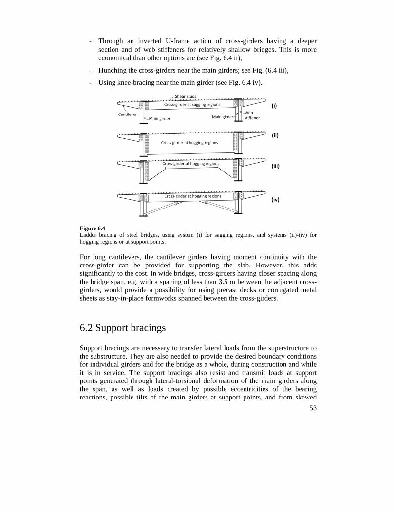
53
- Through an inverted U-frame action of cross-girders having a deeper section and of web stiffeners for relatively shallow bridges. This is more economical than other options are (see Fig. 6.4 ii),
- Hunching the cross-girders near the main girders; see Fig. (6.4 iii),
- Using knee-bracing near the main girder (see Fig. 6.4 iv).
Figure 6.4 Ladder bracing of steel bridges, using system (i) for sagging regions, and systems (ii)-(iv) for hogging regions or at support points.
For long cantilevers, the cantilever girders having moment continuity with the cross-girder can be provided for supporting the slab. However, this adds significantly to the cost. In wide bridges, cross-girders having closer spacing along the bridge span, e.g. with a spacing of less than 3.5m between the adjacent cross-girders, would provide a possibility for using precast decks or corrugated metal sheets as stay-in-place formworks spanned between the cross-girders.
6.2 Support bracings
Support bracings are necessary to transfer lateral loads from the superstructure to the substructure. They are also needed to provide the desired boundary conditions for individual girders and for the bridge as a whole, during construction and while it is in service. The support bracings also resist and transmit loads at support points generated through lateral-torsional deformation of the main girders along the span, as well as loads created by possible eccentricities of the bearing reactions, possible tilts of the main girders at support points, and from skewed
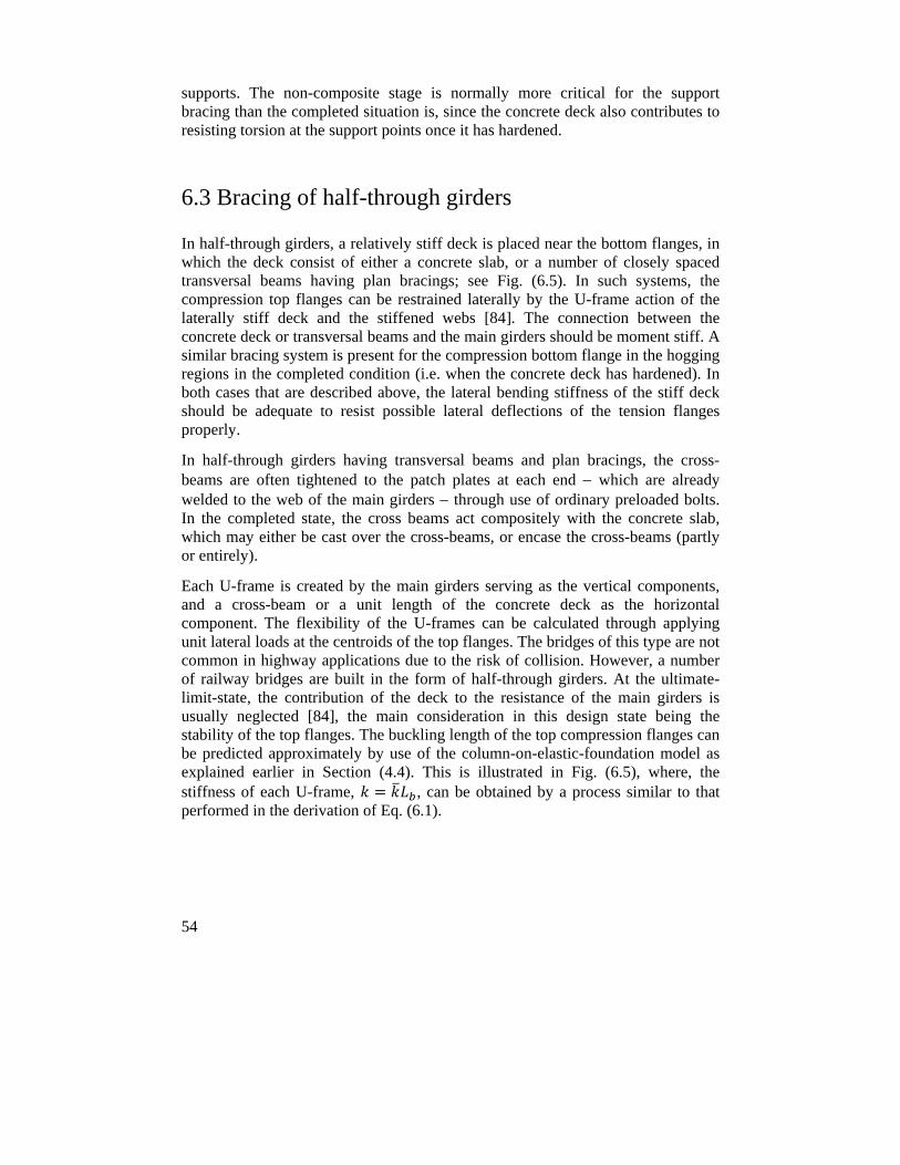
54
supports. The non-composite stage is normally more critical for the support bracing than the completed situation is, since the concrete deck also contributes to resisting torsion at the support points once it has hardened.
6.3 Bracing of half-through girders
In half-through girders, a relatively stiff deck is placed near the bottom flanges, in which the deck consist of either a concrete slab, or a number of closely spaced transversal beams having plan bracings; see Fig. (6.5). In such systems, the compression top flanges can be restrained laterally by the U-frame action of the laterally stiff deck and the stiffened webs [84]. The connection between the concrete deck or transversal beams and the main girders should be moment stiff. A similar bracing system is present for the compression bottom flange in the hogging regions in the completed condition (i.e. when the concrete deck has hardened). In both cases that are described above, the lateral bending stiffness of the stiff deck should be adequate to resist possible lateral deflections of the tension flanges properly.
In half-through girders having transversal beams and plan bracings, the cross-beams are often tightened to the patch plates at each end which are already welded to the web of the main girders through use of ordinary preloaded bolts. In the completed state, the cross beams act compositely with the concrete slab, which may either be cast over the cross-beams, or encase the cross-beams (partly or entirely).
Each U-frame is created by the main girders serving as the vertical components, and a cross-beam or a unit length of the concrete deck as the horizontal component. The flexibility of the U-frames can be calculated through applying unit lateral loads at the centroids of the top flanges. The bridges of this type are not common in highway applications due to the risk of collision. However, a number of railway bridges are built in the form of half-through girders. At the ultimate-limit-state, the contribution of the deck to the resistance of the main girders is usually neglected [84], the main consideration in this design state being the stability of the top flanges. The buckling length of the top compression flanges can be predicted approximately by use of the column-on-elastic-foundation model as explained earlier in Section (4.4). This is illustrated in Fig. (6.5), where, the stiffness of each U-frame, , can be obtained by a process similar to that performed in the derivation of Eq. (6.1).
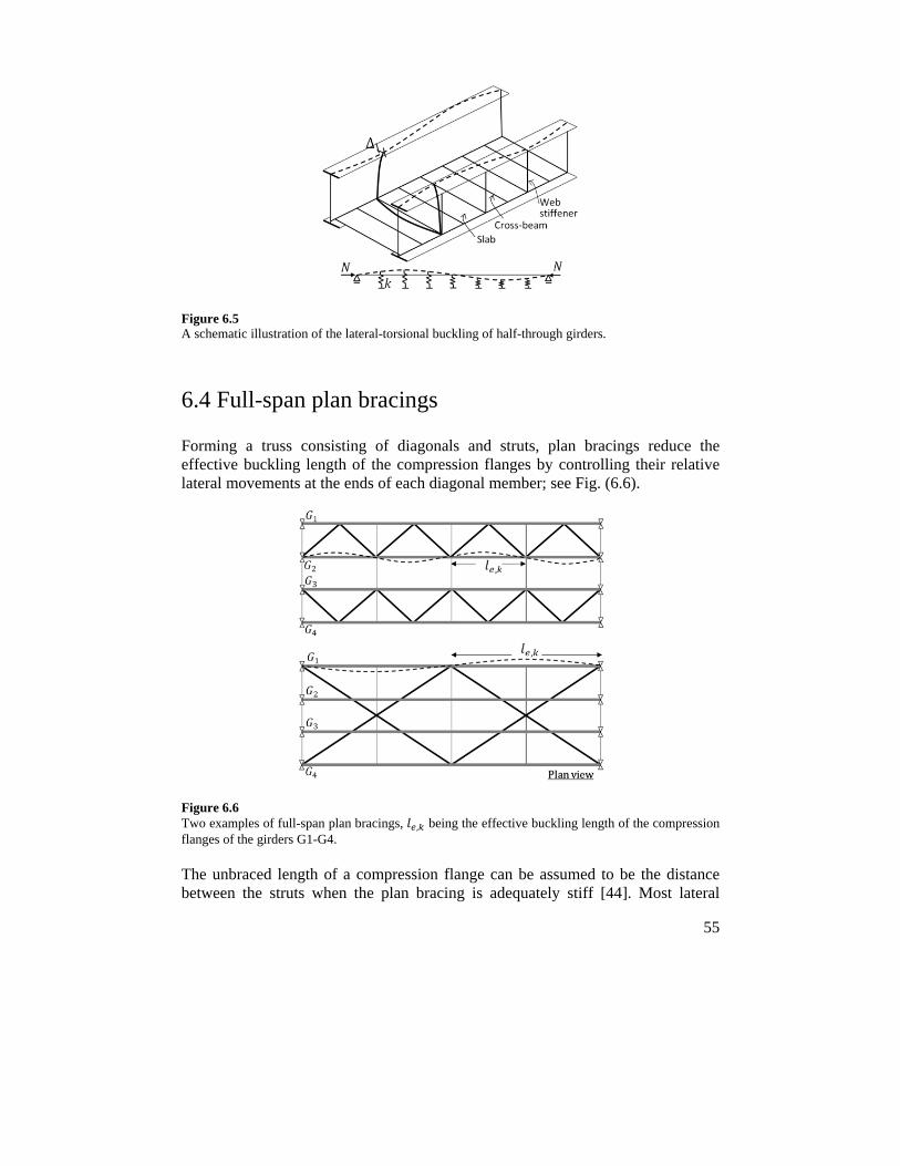
55
Figure 6.5 A schematic illustration of the lateral-torsional buckling of half-through girders.
6.4 Full-span plan bracings
Forming a truss consisting of diagonals and struts, plan bracings reduce the effective buckling length of the compression flanges by controlling their relative lateral movements at the ends of each diagonal member; see Fig. (6.6).
Figure 6.6 Two examples of full-span plan bracings, , being the effective buckling length of the compression flanges of the girders G1-G4.
The unbraced length of a compression flange can be assumed to be the distance between the struts when the plan bracing is adequately stiff [44]. Most lateral
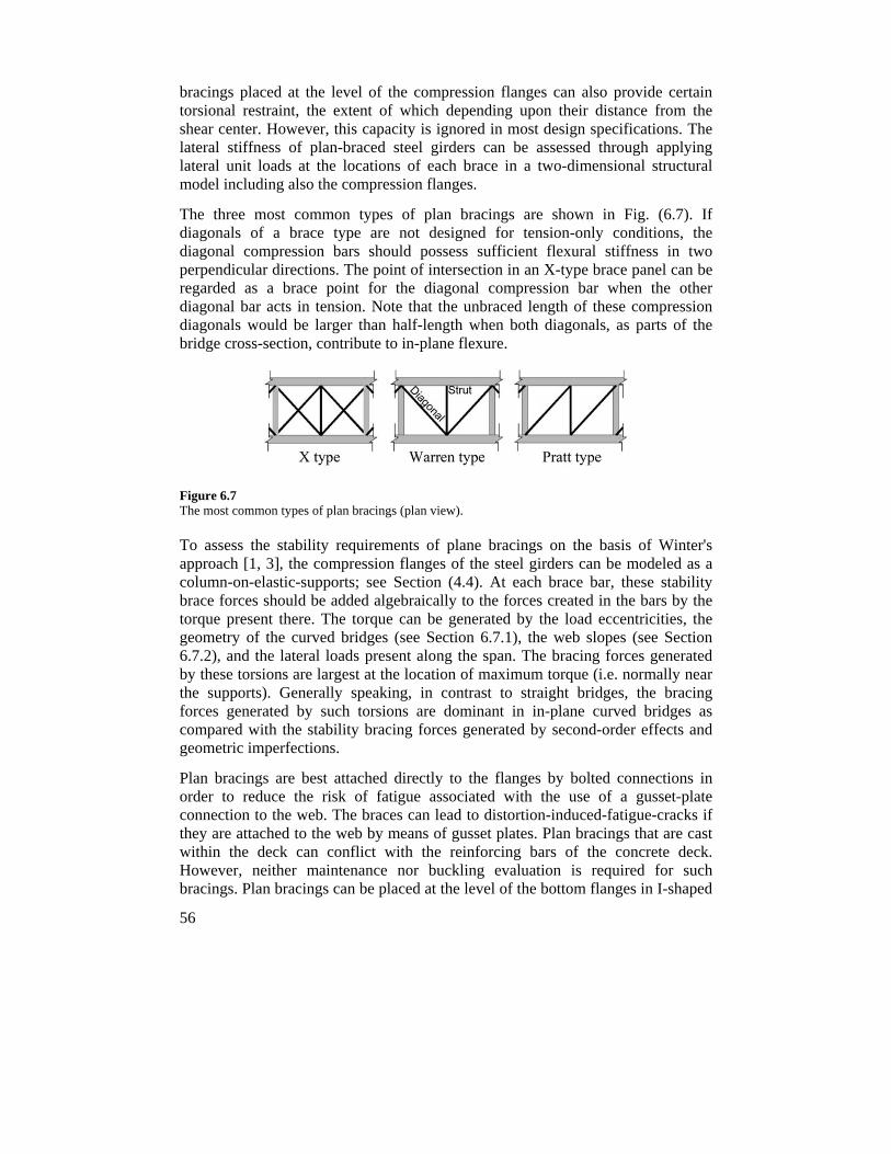
56
bracings placed at the level of the compression flanges can also provide certain torsional restraint, the extent of which depending upon their distance from the shear center. However, this capacity is ignored in most design specifications. The lateral stiffness of plan-braced steel girders can be assessed through applying lateral unit loads at the locations of each brace in a two-dimensional structural model including also the compression flanges.
The three most common types of plan bracings are shown in Fig. (6.7). If diagonals of a brace type are not designed for tension-only conditions, the diagonal compression bars should possess sufficient flexural stiffness in two perpendicular directions. The point of intersection in an X-type brace panel can be regarded as a brace point for the diagonal compression bar when the other diagonal bar acts in tension. Note that the unbraced length of these compression diagonals would be larger than half-length when both diagonals, as parts of the bridge cross-section, contribute to in-plane flexure.
Figure 6.7 The most common types of plan bracings (plan view).
To assess the stability requirements of plane bracings on the basis of Winter's approach [1, 3], the compression flanges of the steel girders can be modeled as a column-on-elastic-supports; see Section (4.4). At each brace bar, these stability brace forces should be added algebraically to the forces created in the bars by the torque present there. The torque can be generated by the load eccentricities, the geometry of the curved bridges (see Section 6.7.1), the web slopes (see Section 6.7.2), and the lateral loads present along the span. The bracing forces generated by these torsions are largest at the location of maximum torque (i.e. normally near the supports). Generally speaking, in contrast to straight bridges, the bracing forces generated by such torsions are dominant in in-plane curved bridges as compared with the stability bracing forces generated by second-order effects and geometric imperfections.
Plan bracings are best attached directly to the flanges by bolted connections in order to reduce the risk of fatigue associated with the use of a gusset-plate connection to the web. The braces can lead to distortion-induced-fatigue-cracks if they are attached to the web by means of gusset plates. Plan bracings that are cast within the deck can conflict with the reinforcing bars of the concrete deck. However, neither maintenance nor buckling evaluation is required for such bracings. Plan bracings can be placed at the level of the bottom flanges in I-shaped
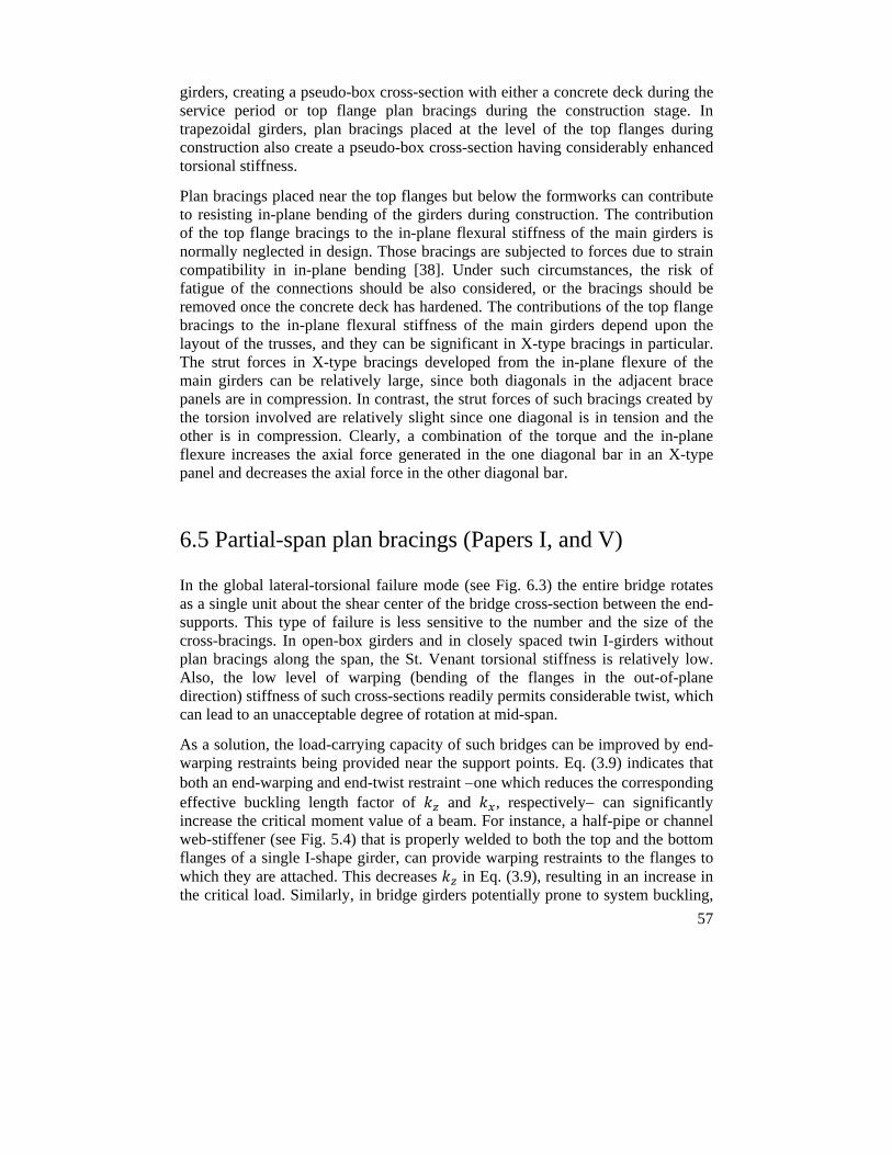
57
girders, creating a pseudo-box cross-section with either a concrete deck during the service period or top flange plan bracings during the construction stage. In trapezoidal girders, plan bracings placed at the level of the top flanges during construction also create a pseudo-box cross-section having considerably enhanced torsional stiffness.
Plan bracings placed near the top flanges but below the formworks can contribute to resisting in-plane bending of the girders during construction. The contribution of the top flange bracings to the in-plane flexural stiffness of the main girders is normally neglected in design. Those bracings are subjected to forces due to strain compatibility in in-plane bending [38]. Under such circumstances, the risk of fatigue of the connections should be also considered, or the bracings should be removed once the concrete deck has hardened. The contributions of the top flange bracings to the in-plane flexural stiffness of the main girders depend upon the layout of the trusses, and they can be significant in X-type bracings in particular. The strut forces in X-type bracings developed from the in-plane flexure of the main girders can be relatively large, since both diagonals in the adjacent brace panels are in compression. In contrast, the strut forces of such bracings created by the torsion involved are relatively slight since one diagonal is in tension and the other is in compression. Clearly, a combination of the torque and the in-plane flexure increases the axial force generated in the one diagonal bar in an X-type panel and decreases the axial force in the other diagonal bar.
6.5 Partial-span plan bracings (Papers I, and V)
In the global lateral-torsional failure mode (see Fig. 6.3) the entire bridge rotates as a single unit about the shear center of the bridge cross-section between the end-supports. This type of failure is less sensitive to the number and the size of the cross-bracings. In open-box girders and in closely spaced twin I-girders without plan bracings along the span, the St. Venant torsional stiffness is relatively low. Also, the low level of warping (bending of the flanges in the out-of-plane direction) stiffness of such cross-sections readily permits considerable twist, which can lead to an unacceptable degree of rotation at mid-span.
As a solution, the load-carrying capacity of such bridges can be improved by end-warping restraints being provided near the support points. Eq. (3.9) indicates that both an end-warping and end-twist restraint one which reduces the corresponding effective buckling length factor of and , respectively can significantly increase the critical moment value of a beam. For instance, a half-pipe or channel web-stiffener (see Fig. 5.4) that is properly welded to both the top and the bottom flanges of a single I-shape girder, can provide warping restraints to the flanges to which they are attached. This decreases in Eq. (3.9), resulting in an increase in the critical load. Similarly, in bridge girders potentially prone to system buckling,
58
plan bracings at support regions (and perhaps at mid-span to prevent further buckling modes) restrain the lateral rotation of the restrained flanges, this decreasing the value of in Eq. (3.9). Such modifications increase the warping stiffness of the cross-section, creating a semi-fixed-end condition, resulting in an increase in the critical moment value. The corresponding critical moment under fixed-end conditions can be calculated through replacing by 0.5 0.6 in Eq. (6.8). Investigations carried out in Paper I [49] concerning the failure of The Marcy Bridge showed that slight truss-bracings near the supports could prevent the collapse of the bridge. End-warping restraints of truss-bracings and corrugated metal sheets were studied experimentally, the results being described in detail in Paper V [85], which is appended to this thesis.
6.6 Bracings required in open trapezoidal girders
Trapezoidal girders require high fabrication costs due to inclination of the webs. In a completed state, bridges of this type have particular advantages when compared with an equivalent twin-I girder bridge, for the following reasons:
i) the bridge possesses greater torsional stiffness, ii) a greater St. Venant stiffness minimizes the self-weight of the steel girder, and iii) the bridge has greater durability due to its having fewer edges and no external stiffeners that are exposed to dirt and to moisture.
However, before the composite action occurs, the open cross-sections are weak torsionally, and can be susceptible to lateral-torsional buckling of the individual webs between the cross-bracings, or to system buckling of the entire bridge between the supports. Increasing the slope of the web and keeping the width of the bottom flange constant increases the lateral stiffness of a trapezoidal cross-section, while reducing the critical moment value [86]. The possibility of lateral-torsional buckling of the trapezoidal cross-sections when they are bent about their weak axis (i.e. in-plane bending) has been discussed by Attard [87]. The Marcy Bridge having a trapezoidal cross-section and a lateral-to-in-plane flexural stiffness ratio, / , of 1.75, failed due to system buckling [49, 86].
Comparatively large torsional stiffness values for trapezoidal girders can be achieved converting their cross-section to a pseudo-closed form by use of steel plates, plan bracings, or corrugated metal sheets attached properly to their top flanges. In the closed-section configuration, the torsional stiffness is dominated by the St. Venant component (where 4 /∑ / whereas in an open cross-section ∑ /3). Although in the closed-form the warping stiffness is negligible when compared to the St. Venant stiffness, large warping stresses can develop due to the cross-sectional distortion that can be present when the bridge lacks adequate cross-bracings along the span (see Section 6.6.3).
59
Note that, in the completed situation, longitudinal stiffeners are normally needed in the compressive zones of the inclined webs and of the bottom flange in order to avoid local buckling.
6.6.1 The equivalent plate concept and forces generated in plan-bracings by torsion
Kollbrunner and Basler [2] derived expressions enabling typical truss bracings to be converted to an equivalent plate having a constant thickness of ; see Appendix IV. The equivalent plate is used to calculate the mechanical properties of such cross-sections in order to assure that the torsional stiffness and strength are sufficient to keep rotations and stresses within a magnitude of reasonable size. The equivalent plate concept is also used in calculating the cross-sectional properties of trapezoidal girders on the top of which corrugated metal sheets are attached (see Section 2.2.1). However, the stress concentration factor needs to be taken into account there, due to large changes that often occur in the thickness of the plates. Note that relatively little research has been done to assure the accuracy of the equivalent plate method in such applications. The St. Venant shear flow in the equivalent plate (see Eq. 6.9) creates axial forces in the brace bars (see Fig. 6.8).
2 6.9
Where is the shear flow, is the enclosed area as defined by the wall-midline in a thin-walled closed section, and the torque at the middle of each panel, , is generated by the geometry of curved bridges or by eccentric gravity load across the width of a bridge cross-section, for example.
Figure 6.8 Forces that develop in plan bracing bars, and , due to the torsion, there, being the shear flow and being the enclosed area as defined by the wall-midline in a thin-walled closed section.
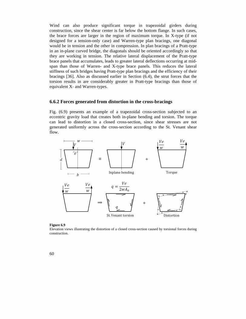
60
Wind can also produce significant torque in trapezoidal girders during construction, since the shear center is far below the bottom flange. In such cases, the brace forces are larger in the region of maximum torque. In X-type (if not designed for a tension-only case) and Warren-type plan bracings, one diagonal would be in tension and the other in compression. In plan bracings of a Pratt-type in an in-plane curved bridge, the diagonals should be oriented accordingly so that they are working in tension. The relative lateral displacement of the Pratt-type brace panels that accumulates, leads to greater lateral deflections occurring at mid-span than those of Warren- and X-type brace panels. This reduces the lateral stiffness of such bridges having Pratt-type plan bracings and the efficiency of their bracings [36]. Also as discussed earlier in Section (6.4), the strut forces that the torsion results in are considerably greater in Pratt-type bracings than those of equivalent X- and Warren-types.
6.6.2 Forces generated from distortion in the cross-bracings
Fig. (6.9) presents an example of a trapezoidal cross-section subjected to an eccentric gravity load that creates both in-plane bending and torsion. The torque can lead to distortion in a closed cross-section, since shear stresses are not generated uniformly across the cross-section according to the St. Venant shear flow.
Figure 6.9 Elevation views illustrating the distortion of a closed cross-section caused by torsional forces during construction.
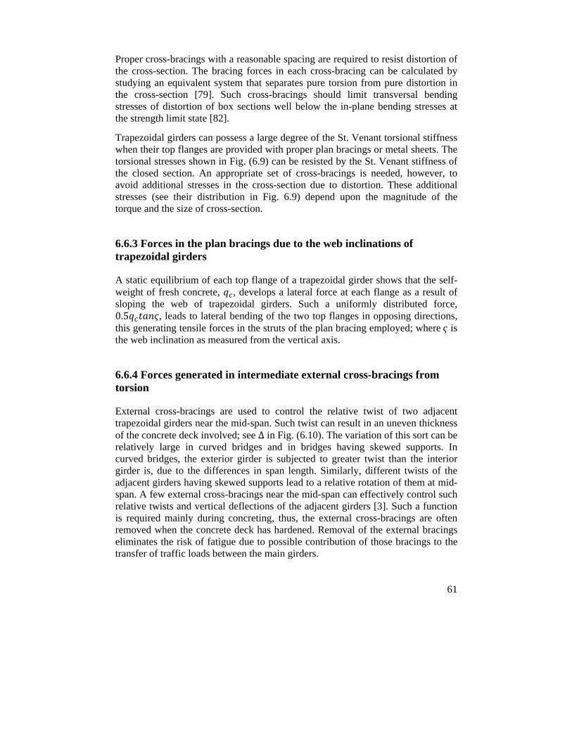
61
Proper cross-bracings with a reasonable spacing are required to resist distortion of the cross-section. The bracing forces in each cross-bracing can be calculated by studying an equivalent system that separates pure torsion from pure distortion in the cross-section [79]. Such cross-bracings should limit transversal bending stresses of distortion of box sections well below the in-plane bending stresses at the strength limit state [82].
Trapezoidal girders can possess a large degree of the St. Venant torsional stiffness when their top flanges are provided with proper plan bracings or metal sheets. The torsional stresses shown in Fig. (6.9) can be resisted by the St. Venant stiffness of the closed section. An appropriate set of cross-bracings is needed, however, to avoid additional stresses in the cross-section due to distortion. These additional stresses (see their distribution in Fig. 6.9) depend upon the magnitude of the torque and the size of cross-section.
6.6.3 Forces in the plan bracings due to the web inclinations of trapezoidal girders
A static equilibrium of each top flange of a trapezoidal girder shows that the self-weight of fresh concrete, , develops a lateral force at each flange as a result of sloping the web of trapezoidal girders. Such a uniformly distributed force, 0.5 , leads to lateral bending of the two top flanges in opposing directions, this generating tensile forces in the struts of the plan bracing employed; where is the web inclination as measured from the vertical axis.
6.6.4 Forces generated in intermediate external cross-bracings from torsion
External cross-bracings are used to control the relative twist of two adjacent trapezoidal girders near the mid-span. Such twist can result in an uneven thickness of the concrete deck involved; see ∆ in Fig. (6.10). The variation of this sort can be relatively large in curved bridges and in bridges having skewed supports. In curved bridges, the exterior girder is subjected to greater twist than the interior girder is, due to the differences in span length. Similarly, different twists of the adjacent girders having skewed supports lead to a relative rotation of them at mid-span. A few external cross-bracings near the mid-span can effectively control such relative twists and vertical deflections of the adjacent girders [3]. Such a function is required mainly during concreting, thus, the external cross-bracings are often removed when the concrete deck has hardened. Removal of the external bracings eliminates the risk of fatigue due to possible contribution of those bracings to the transfer of traffic loads between the main girders.
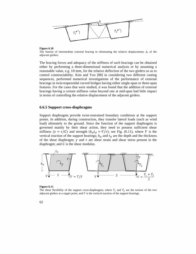
62
Figure 6.10 The functio of intermediate external bracing in eliminating the relative displacement, ∆, of the adjucent girders.
The bracing forces and adequacy of the stiffness of such bracings can be obtained either by performing a three-dimensional numerical analysis or by assuming a reasonable value, e.g.10mm, for the relative deflection of the two girders so as to control constructability. Kim and Yoo [88] in considering two different casting sequences, performed numerical investigations of the performance of external bracings in twin-trapezoidal curved bridges having either single-span or three-span features. For the cases that were studied, it was found that the addition of external bracings having a certain stiffness value beyond one at mid-span had little impact in terms of controlling the relative displacement of the adjacent girders.
6.6.5 Support cross-diaphragms
Support diaphragms provide twist-restrained boundary conditions at the support points. In addition, during construction, they transfer lateral loads (such as wind load) ultimately to the ground. Since the function of the support diaphragms is governed mainly by their shear action, they need to possess sufficient shear stiffness / and strength ( / ; see Fig. (6.11), where is the vertical reaction of the support bearings; and are the depth and the thickness of the shear diaphragm; and are shear strain and shear stress present in the diaphragm; and is the shear modulus.
Figure 6.11 The shear flexibility of the support cross-diaphragms; where and are the torsion of the two adjacent girders at a supprt point, and is the vertical reaction of the support bearings.
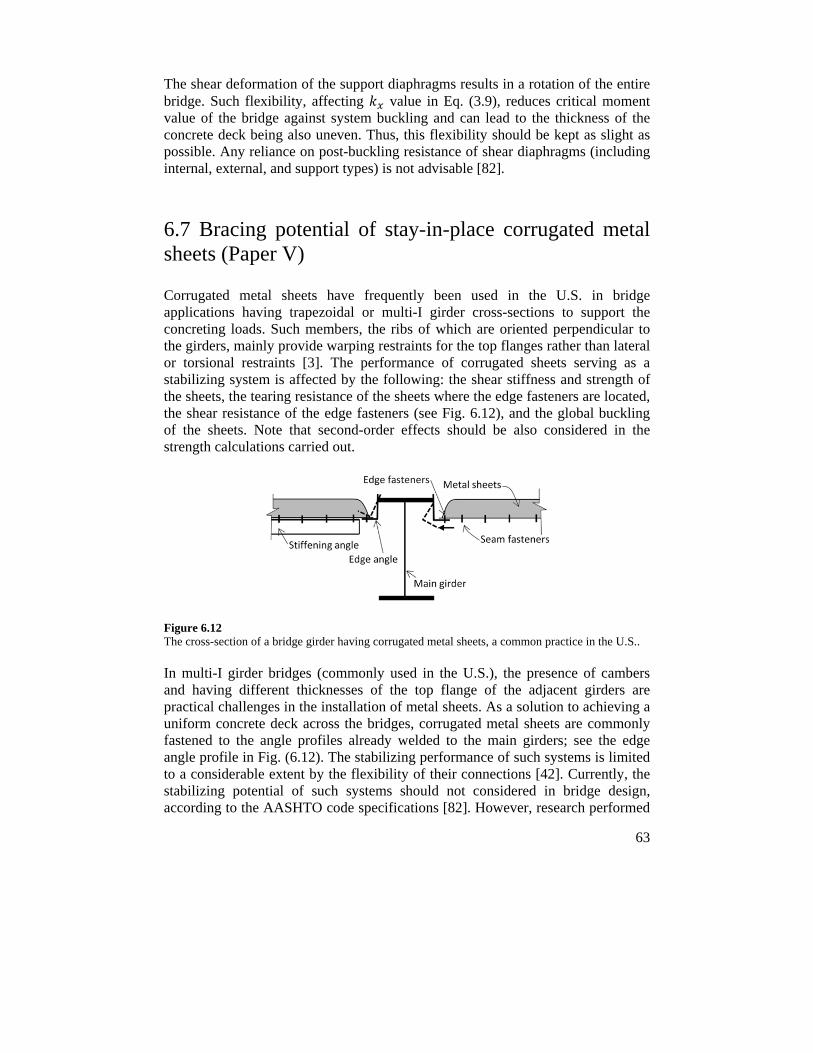
63
The shear deformation of the support diaphragms results in a rotation of the entire bridge. Such flexibility, affecting value in Eq. (3.9), reduces critical moment value of the bridge against system buckling and can lead to the thickness of the concrete deck being also uneven. Thus, this flexibility should be kept as slight as possible. Any reliance on post-buckling resistance of shear diaphragms (including internal, external, and support types) is not advisable [82].
6.7 Bracing potential of stay-in-place corrugated metal sheets (Paper V)
Corrugated metal sheets have frequently been used in the U.S. in bridge applications having trapezoidal or multi-I girder cross-sections to support the concreting loads. Such members, the ribs of which are oriented perpendicular to the girders, mainly provide warping restraints for the top flanges rather than lateral or torsional restraints [3]. The performance of corrugated sheets serving as a stabilizing system is affected by the following: the shear stiffness and strength of the sheets, the tearing resistance of the sheets where the edge fasteners are located, the shear resistance of the edge fasteners (see Fig. 6.12), and the global buckling of the sheets. Note that second-order effects should be also considered in the strength calculations carried out.
Figure 6.12 The cross-section of a bridge girder having corrugated metal sheets, a common practice in the U.S..
In multi-I girder bridges (commonly used in the U.S.), the presence of cambers and having different thicknesses of the top flange of the adjacent girders are practical challenges in the installation of metal sheets. As a solution to achieving a uniform concrete deck across the bridges, corrugated metal sheets are commonly fastened to the angle profiles already welded to the main girders; see the edge angle profile in Fig. (6.12). The stabilizing performance of such systems is limited to a considerable extent by the flexibility of their connections [42]. Currently, the stabilizing potential of such systems should not considered in bridge design, according to the AASHTO code specifications [82]. However, research performed
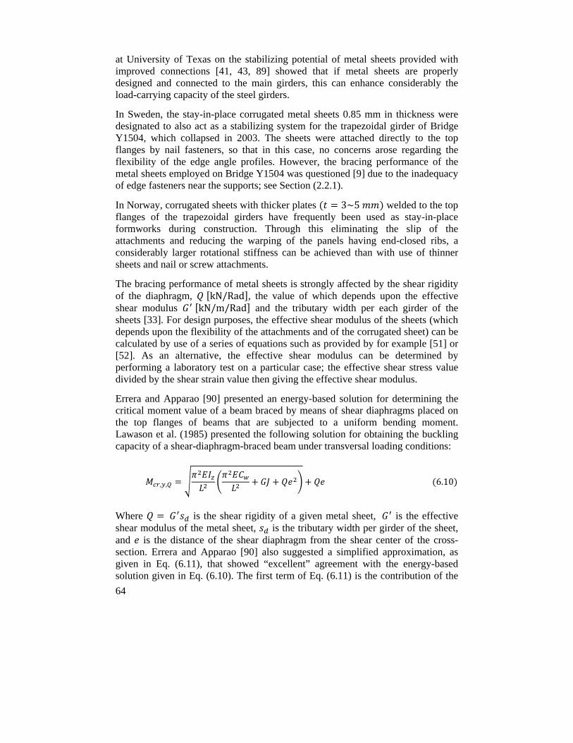
64
at University of Texas on the stabilizing potential of metal sheets provided with improved connections [41, 43, 89] showed that if metal sheets are properly designed and connected to the main girders, this can enhance considerably the load-carrying capacity of the steel girders.
In Sweden, the stay-in-place corrugated metal sheets 0.85 mm in thickness were designated to also act as a stabilizing system for the trapezoidal girder of Bridge Y1504, which collapsed in 2003. The sheets were attached directly to the top flanges by nail fasteners, so that in this case, no concerns arose regarding the flexibility of the edge angle profiles. However, the bracing performance of the metal sheets employed on Bridge Y1504 was questioned [9] due to the inadequacy of edge fasteners near the supports; see Section (2.2.1).
In Norway, corrugated sheets with thicker plates 3~5 welded to the top flanges of the trapezoidal girders have frequently been used as stay-in-place formworks during construction. Through this eliminating the slip of the attachments and reducing the warping of the panels having end-closed ribs, a considerably larger rotational stiffness can be achieved than with use of thinner sheets and nail or screw attachments.
The bracing performance of metal sheets is strongly affected by the shear rigidity of the diaphragm, kN/Rad , the value of which depends upon the effective shear modulus kN/m/Rad and the tributary width per each girder of the sheets [33]. For design purposes, the effective shear modulus of the sheets (which depends upon the flexibility of the attachments and of the corrugated sheet) can be calculated by use of a series of equations such as provided by for example [51] or [52]. As an alternative, the effective shear modulus can be determined by performing a laboratory test on a particular case; the effective shear stress value divided by the shear strain value then giving the effective shear modulus.
Errera and Apparao [90] presented an energy-based solution for determining the critical moment value of a beam braced by means of shear diaphragms placed on the top flanges of beams that are subjected to a uniform bending moment. Lawason et al. (1985) presented the following solution for obtaining the buckling capacity of a shear-diaphragm-braced beam under transversal loading conditions:
, , 6.10
Where is the shear rigidity of a given metal sheet, is the effective shear modulus of the metal sheet, is the tributary width per girder of the sheet, and is the distance of the shear diaphragm from the shear center of the cross-section. Errera and Apparao [90] also suggested a simplified approximation, as given in Eq. (6.11), that showed “excellent” agreement with the energy-based solution given in Eq. (6.10). The first term of Eq. (6.11) is the contribution of the
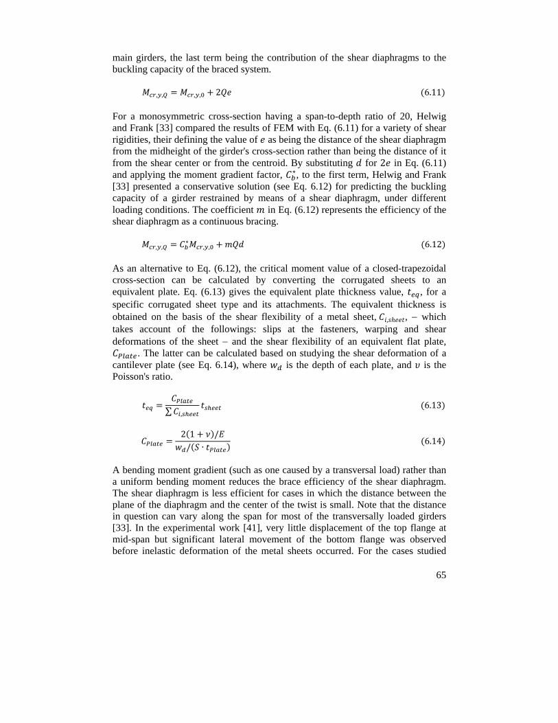
65
main girders, the last term being the contribution of the shear diaphragms to the buckling capacity of the braced system.
, , , , 2 6.11
For a monosymmetric cross-section having a span-to-depth ratio of 20, Helwig and Frank [33] compared the results of FEM with Eq. (6.11) for a variety of shear rigidities, their defining the value of as being the distance of the shear diaphragm from the midheight of the girder's cross-section rather than being the distance of it from the shear center or from the centroid. By substituting for 2 in Eq. (6.11) and applying the moment gradient factor, ∗, to the first term, Helwig and Frank [33] presented a conservative solution (see Eq. 6.12) for predicting the buckling capacity of a girder restrained by means of a shear diaphragm, under different loading conditions. The coefficient in Eq. (6.12) represents the efficiency of the shear diaphragm as a continuous bracing.
, ,∗
, , 6.12
As an alternative to Eq. (6.12), the critical moment value of a closed-trapezoidal cross-section can be calculated by converting the corrugated sheets to an equivalent plate. Eq. (6.13) gives the equivalent plate thickness value, , for a specific corrugated sheet type and its attachments. The equivalent thickness is obtained on the basis of the shear flexibility of a metal sheet, , , which takes account of the followings: slips at the fasteners, warping and shear deformations of the sheet and the shear flexibility of an equivalent flat plate,
. The latter can be calculated based on studying the shear deformation of a cantilever plate (see Eq. 6.14), where is the depth of each plate, and is the Poisson's ratio.
∑ , 6.13
2 1 // ∙
6.14
A bending moment gradient (such as one caused by a transversal load) rather than a uniform bending moment reduces the brace efficiency of the shear diaphragm. The shear diaphragm is less efficient for cases in which the distance between the plane of the diaphragm and the center of the twist is small. Note that the distance in question can vary along the span for most of the transversally loaded girders [33]. In the experimental work [41], very little displacement of the top flange at mid-span but significant lateral movement of the bottom flange was observed before inelastic deformation of the metal sheets occurred. For the cases studied
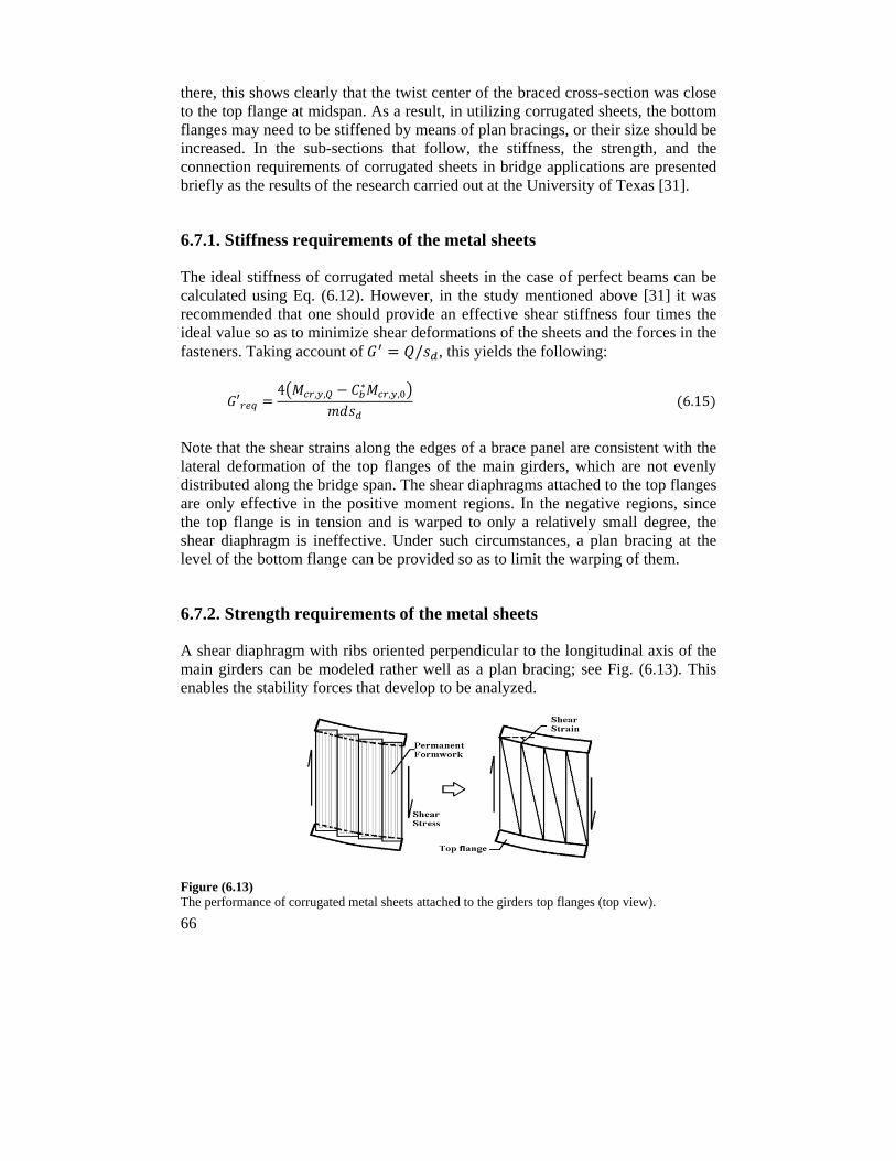
66
there, this shows clearly that the twist center of the braced cross-section was close to the top flange at midspan. As a result, in utilizing corrugated sheets, the bottom flanges may need to be stiffened by means of plan bracings, or their size should be increased. In the sub-sections that follow, the stiffness, the strength, and the connection requirements of corrugated sheets in bridge applications are presented briefly as the results of the research carried out at the University of Texas [31].
6.7.1. Stiffness requirements of the metal sheets
The ideal stiffness of corrugated metal sheets in the case of perfect beams can be calculated using Eq. (6.12). However, in the study mentioned above [31] it was recommended that one should provide an effective shear stiffness four times the ideal value so as to minimize shear deformations of the sheets and the forces in the fasteners. Taking account of / , this yields the following:
′4 , ,
∗, , 6.15
Note that the shear strains along the edges of a brace panel are consistent with the lateral deformation of the top flanges of the main girders, which are not evenly distributed along the bridge span. The shear diaphragms attached to the top flanges are only effective in the positive moment regions. In the negative regions, since the top flange is in tension and is warped to only a relatively small degree, the shear diaphragm is ineffective. Under such circumstances, a plan bracing at the level of the bottom flange can be provided so as to limit the warping of them.
6.7.2. Strength requirements of the metal sheets
A shear diaphragm with ribs oriented perpendicular to the longitudinal axis of the main girders can be modeled rather well as a plan bracing; see Fig. (6.13). This enables the stability forces that develop to be analyzed.
Figure (6.13) The performance of corrugated metal sheets attached to the girders top flanges (top view).
67
The bracing forces there depend upon the magnitude of the initial imperfections (larger forces being created in the case of larger initial imperfections), the actual brace stiffness (smaller forces being created by stiffer sheets), the web flexibility, and the loading conditions. The magnitude of the bracing moment per unit length of the bridge span (see . / in Fig. 6.14) generated in a shear diaphragm attached to the top flanges follows the lateral slope of the flanges; where / ; /2; and are the geometries of each brace panel as shown in Fig. (6.14); and is the shear force that each panel is exposed to at its edges. For a simply supported beam under uniform bending moment conditions, the maximum bracing moment occurs near the supports and gradually decreases along the span. Whereas under a uniformly distributed load or a pointed load at midspan, both of them applied at the level of the neutral axis, the maximum force occurs at a quarter to a third span of the beam [32]. Clearly, the top flange loading increases the bracing moment and the magnitude of the maximum twist as compared to loading at the level of the neutral axis.
Assuming a stiffness value of 4 being provided for the corrugated sheets, Helwig and Yura [31] recommended use of the following bracing moment value for design purposes:
0.001 6.16
Note that Eq. (6.16) should be modified when loading other than a uniformly distributed load being applied at the level of the top flanges is present, and if the shear stiffness of less than 4 is provided.
The center of twist for a braced I-girder with a top flange loading is near to the top flanges, much of the cross-sectional twist occurring due to the lateral deformation of the bottom flange. The recommendations above are given for I-girders with no cross-bracings between the supports. A combination of corrugated sheets with cross-bracings along the span can make the metal sheets more effective. Utilizing cross-bracing generally reduces the bracing forces and the required stiffness of the shear diaphragms [32].
6.7.3. Connection requirements
The shear forces created in the fasteners, and , caused by the brace shear forces, , can be determined by studying the equilibrium of a given brace panel [31]. For the case shown in Fig. (6.14), for example, in which there exist five edge fasteners for each corrugated sheet, the resultant shear force created in the most loaded fastener is:
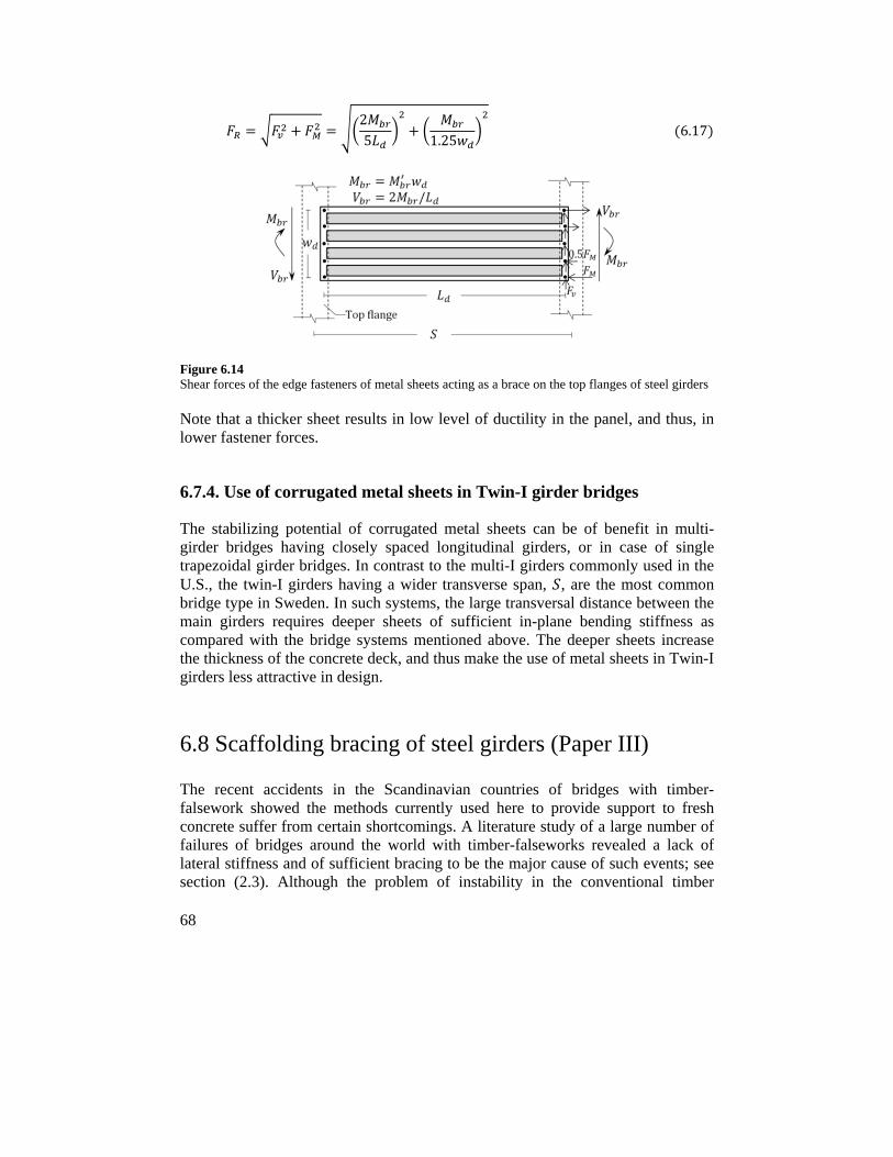
68
25 1.25
6.17
Figure 6.14 Shear forces of the edge fasteners of metal sheets acting as a brace on the top flanges of steel girders
Note that a thicker sheet results in low level of ductility in the panel, and thus, in lower fastener forces.
6.7.4. Use of corrugated metal sheets in Twin-I girder bridges
The stabilizing potential of corrugated metal sheets can be of benefit in multi-girder bridges having closely spaced longitudinal girders, or in case of single trapezoidal girder bridges. In contrast to the multi-I girders commonly used in the U.S., the twin-I girders having a wider transverse span, , are the most common bridge type in Sweden. In such systems, the large transversal distance between the main girders requires deeper sheets of sufficient in-plane bending stiffness as compared with the bridge systems mentioned above. The deeper sheets increase the thickness of the concrete deck, and thus make the use of metal sheets in Twin-I girders less attractive in design.
6.8 Scaffolding bracing of steel girders (Paper III)
The recent accidents in the Scandinavian countries of bridges with timber-falsework showed the methods currently used here to provide support to fresh concrete suffer from certain shortcomings. A literature study of a large number of failures of bridges around the world with timber-falseworks revealed a lack of lateral stiffness and of sufficient bracing to be the major cause of such events; see section (2.3). Although the problem of instability in the conventional timber
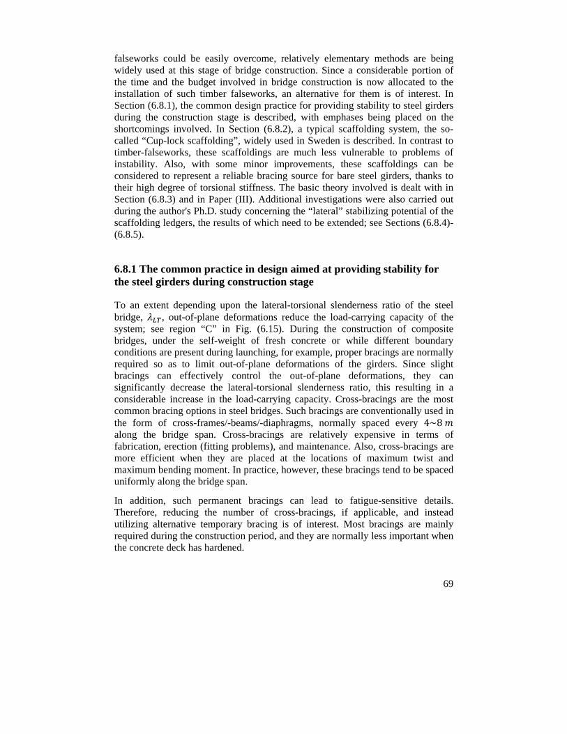
69
falseworks could be easily overcome, relatively elementary methods are being widely used at this stage of bridge construction. Since a considerable portion of the time and the budget involved in bridge construction is now allocated to the installation of such timber falseworks, an alternative for them is of interest. In Section (6.8.1), the common design practice for providing stability to steel girders during the construction stage is described, with emphases being placed on the shortcomings involved. In Section (6.8.2), a typical scaffolding system, the so-called “Cup-lock scaffolding”, widely used in Sweden is described. In contrast to timber-falseworks, these scaffoldings are much less vulnerable to problems of instability. Also, with some minor improvements, these scaffoldings can be considered to represent a reliable bracing source for bare steel girders, thanks to their high degree of torsional stiffness. The basic theory involved is dealt with in Section (6.8.3) and in Paper (III). Additional investigations were also carried out during the author's Ph.D. study concerning the “lateral” stabilizing potential of the scaffolding ledgers, the results of which need to be extended; see Sections (6.8.4)-(6.8.5).
6.8.1 The common practice in design aimed at providing stability for the steel girders during construction stage
To an extent depending upon the lateral-torsional slenderness ratio of the steel bridge, , out-of-plane deformations reduce the load-carrying capacity of the system; see region “C” in Fig. (6.15). During the construction of composite bridges, under the self-weight of fresh concrete or while different boundary conditions are present during launching, for example, proper bracings are normally required so as to limit out-of-plane deformations of the girders. Since slight bracings can effectively control the out-of-plane deformations, they can significantly decrease the lateral-torsional slenderness ratio, this resulting in a considerable increase in the load-carrying capacity. Cross-bracings are the most common bracing options in steel bridges. Such bracings are conventionally used in the form of cross-frames/-beams/-diaphragms, normally spaced every 4~8 along the bridge span. Cross-bracings are relatively expensive in terms of fabrication, erection (fitting problems), and maintenance. Also, cross-bracings are more efficient when they are placed at the locations of maximum twist and maximum bending moment. In practice, however, these bracings tend to be spaced uniformly along the bridge span.
In addition, such permanent bracings can lead to fatigue-sensitive details. Therefore, reducing the number of cross-bracings, if applicable, and instead utilizing alternative temporary bracing is of interest. Most bracings are mainly required during the construction period, and they are normally less important when the concrete deck has hardened.
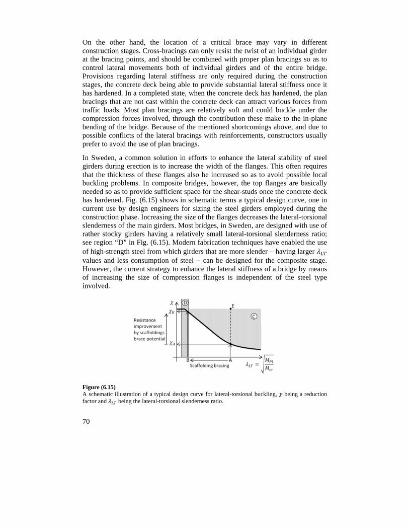
70
On the other hand, the location of a critical brace may vary in different construction stages. Cross-bracings can only resist the twist of an individual girder at the bracing points, and should be combined with proper plan bracings so as to control lateral movements both of individual girders and of the entire bridge. Provisions regarding lateral stiffness are only required during the construction stages, the concrete deck being able to provide substantial lateral stiffness once it has hardened. In a completed state, when the concrete deck has hardened, the plan bracings that are not cast within the concrete deck can attract various forces from traffic loads. Most plan bracings are relatively soft and could buckle under the compression forces involved, through the contribution these make to the in-plane bending of the bridge. Because of the mentioned shortcomings above, and due to possible conflicts of the lateral bracings with reinforcements, constructors usually prefer to avoid the use of plan bracings.
In Sweden, a common solution in efforts to enhance the lateral stability of steel girders during erection is to increase the width of the flanges. This often requires that the thickness of these flanges also be increased so as to avoid possible local buckling problems. In composite bridges, however, the top flanges are basically needed so as to provide sufficient space for the shear-studs once the concrete deck has hardened. Fig. (6.15) shows in schematic terms a typical design curve, one in current use by design engineers for sizing the steel girders employed during the construction phase. Increasing the size of the flanges decreases the lateral-torsional slenderness of the main girders. Most bridges, in Sweden, are designed with use of rather stocky girders having a relatively small lateral-torsional slenderness ratio; see region “D” in Fig. (6.15). Modern fabrication techniques have enabled the use of high-strength steel from which girders that are more slender having larger values and less consumption of steel can be designed for the composite stage. However, the current strategy to enhance the lateral stiffness of a bridge by means of increasing the size of compression flanges is independent of the steel type involved.
Figure (6.15) A schematic illustration of a typical design curve for lateral-torsional buckling, being a reduction factor and being the lateral-torsional slenderness ratio.
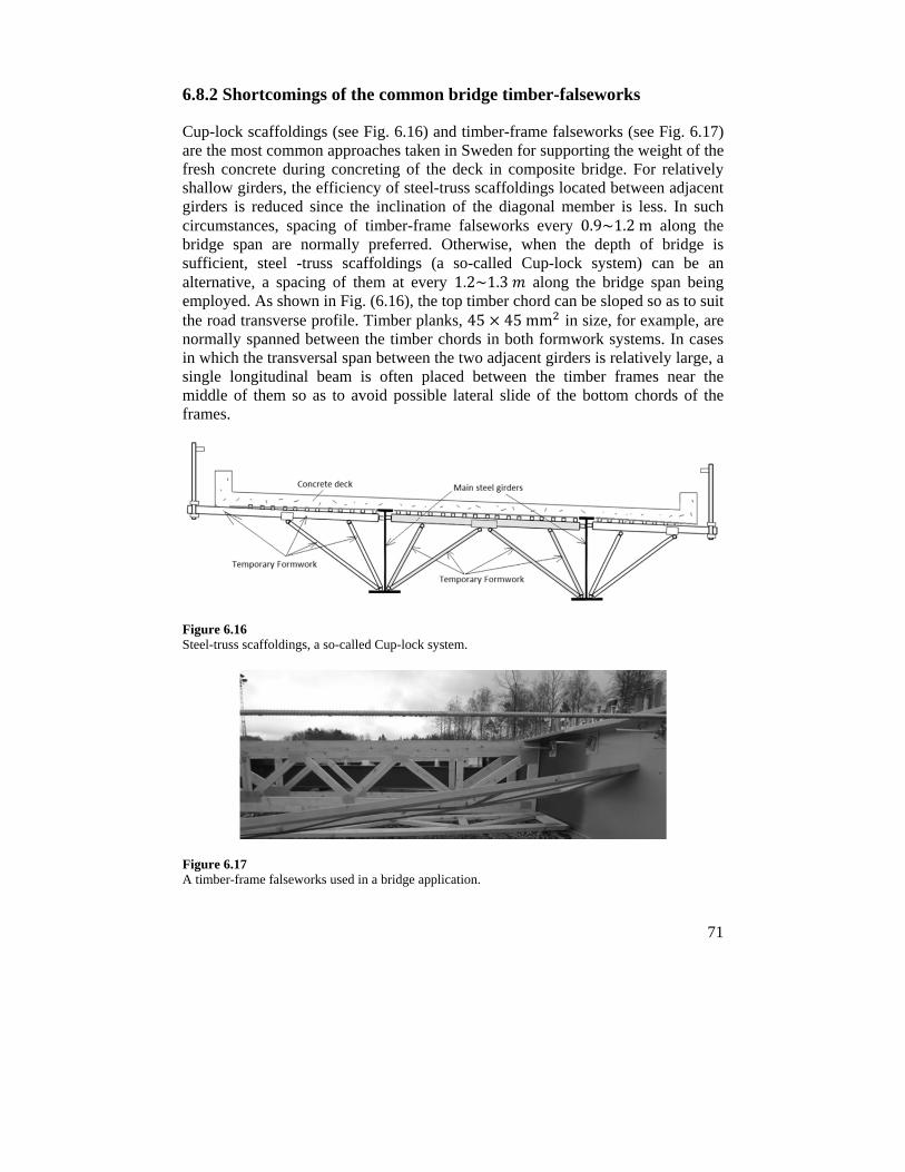
71
6.8.2 Shortcomings of the common bridge timber-falseworks
Cup-lock scaffoldings (see Fig. 6.16) and timber-frame falseworks (see Fig. 6.17) are the most common approaches taken in Sweden for supporting the weight of the fresh concrete during concreting of the deck in composite bridge. For relatively shallow girders, the efficiency of steel-truss scaffoldings located between adjacent girders is reduced since the inclination of the diagonal member is less. In such circumstances, spacing of timber-frame falseworks every 0.9~1.2m along the bridge span are normally preferred. Otherwise, when the depth of bridge is sufficient, steel -truss scaffoldings (a so-called Cup-lock system) can be an alternative, a spacing of them at every 1.2~1.3 along the bridge span being employed. As shown in Fig. (6.16), the top timber chord can be sloped so as to suit the road transverse profile. Timber planks, 45 45mm in size, for example, are normally spanned between the timber chords in both formwork systems. In cases in which the transversal span between the two adjacent girders is relatively large, a single longitudinal beam is often placed between the timber frames near the middle of them so as to avoid possible lateral slide of the bottom chords of the frames.
Figure 6.16 Steel-truss scaffoldings, a so-called Cup-lock system.
Figure 6.17 A timber-frame falseworks used in a bridge application.
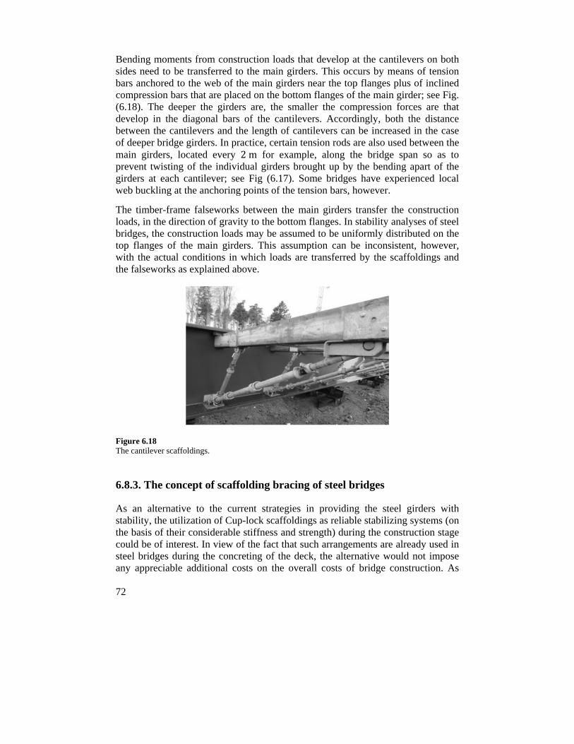
72
Bending moments from construction loads that develop at the cantilevers on both sides need to be transferred to the main girders. This occurs by means of tension bars anchored to the web of the main girders near the top flanges plus of inclined compression bars that are placed on the bottom flanges of the main girder; see Fig. (6.18). The deeper the girders are, the smaller the compression forces are that develop in the diagonal bars of the cantilevers. Accordingly, both the distance between the cantilevers and the length of cantilevers can be increased in the case of deeper bridge girders. In practice, certain tension rods are also used between the main girders, located every 2m for example, along the bridge span so as to prevent twisting of the individual girders brought up by the bending apart of the girders at each cantilever; see Fig (6.17). Some bridges have experienced local web buckling at the anchoring points of the tension bars, however.
The timber-frame falseworks between the main girders transfer the construction loads, in the direction of gravity to the bottom flanges. In stability analyses of steel bridges, the construction loads may be assumed to be uniformly distributed on the top flanges of the main girders. This assumption can be inconsistent, however, with the actual conditions in which loads are transferred by the scaffoldings and the falseworks as explained above.
Figure 6.18 The cantilever scaffoldings.
6.8.3. The concept of scaffolding bracing of steel bridges
As an alternative to the current strategies in providing the steel girders with stability, the utilization of Cup-lock scaffoldings as reliable stabilizing systems (on the basis of their considerable stiffness and strength) during the construction stage could be of interest. In view of the fact that such arrangements are already used in steel bridges during the concreting of the deck, the alternative would not impose any appreciable additional costs on the overall costs of bridge construction. As
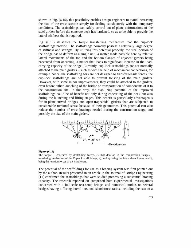
73
shown in Fig. (6.15), this possibility enables design engineers to avoid increasing the size of the cross-section simply for dealing satisfactorily with the temporary conditions. The scaffoldings can safely control out-of-plane deformations of the steel girders before the concrete deck has hardened, so as to be able to provide the lateral stiffness that is required.
Fig. (6.19) illustrates the torque transferring mechanism that the cup-lock scaffoldings provide. The scaffoldings normally possess a relatively large degree of stiffness and strength. By utilizing this potential properly, the steel portion of the bridge has to deform as a single unit, a matter made possible here by relative lateral movements of the top and the bottom flanges of adjacent girders being prevented from occurring, a matter that leads to significant increase in the load-carrying capacity of the bridge. Currently, cup-lock scaffoldings are not normally attached to the main girders such as with the help of mechanical connections, for example. Since, the scaffolding bars are not designed to transfer tensile forces, the cup-lock scaffoldings are not able to prevent twisting of the main girders. However, with some minor improvements, they could be attached to the girders, even before either launching of the bridge or transportation of components of it to the construction site. In this way, the stabilizing potential of the improved scaffoldings could be of benefit not only during concreting of the deck but also during the launching and lifting stages. This benefit is particularly advantageous for in-plane-curved bridges and open-trapezoidal girders that are subjected to considerable torsional stress because of their geometries. This potential can also reduce the number of cross-bracings needed during the construction stage, and possibly the size of the main girders.
Figure (6.19) The torque generated by destabiling forces, , that develop in the compression flanges transfering mechanism of the Cuplock scaffoldings, , and being the brace shear forces, and being the reaction forces of the cantilevers.
The potential of the scaffoldings for use as a bracing system was first pointed out by the author. Results presented in an article in the Journal of Bridge Engineering [11] confirmed the scaffoldings that were studied possessing a substantial bracing capacity. The research reported on comprised both experimental investigations concerned with a full-scale test-setup bridge, and numerical studies on several bridges having differing lateral-torsional slenderness ratios, including the case of a
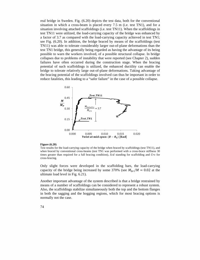
74
real bridge in Sweden. Fig. (6.20) depicts the test data, both for the conventional situation in which a cross-beam is placed every 7.5 m (i.e. test TN1), and for a situation involving attached scaffoldings (i.e. test TN11). When the scaffoldings in test TN11 were utilized, the load-carrying capacity of the bridge was enhanced by a factor of 3.7 as compared with the load-carrying capacity achieved in test TN1; see Fig. (6.20). In addition, the bridge braced by means of the scaffoldings (test TN11) was able to tolerate considerably larger out-of-plane deformations than the test TN1 bridge, this generally being regarded as having the advantage of its being possible to warn the workers involved, of a possible structural collapse. In bridge collapses due to problems of instability that were reported (see Chapter 2), sudden failures have often occurred during the construction stage. When the bracing potential of such scaffoldings is utilized, the enhanced ductility can enable the bridge to tolerate relatively large out-of-plane deformations. Taking advantage of the bracing potential of the scaffoldings involved can thus be important in order to reduce fatalities, this leading to a “safer failure” in the case of a possible collapse.
Figure (6.20) Test results for the load-carrying capacity of the bridge when braced by scaffoldings (test TN11), and when braced by conventional cross-beams (test TN1 was performed with a cross-brace stiffness 30 times greater than required for a full bracing condition), standing for scaffolding and for cross-bracing.
Only slight forces were developed in the scaffolding bars, the load-carrying capacity of the bridge being increased by some 370% (see / 0.02 at the ultimate load level in Fig. 6.21).
Another important advantage of the system described is that a bridge restrained by means of a number of scaffoldings can be considered to represent a robust system. Also, the scaffoldings stabilize simultaneously both the top and the bottom flanges in both the sagging and the hogging regions, which for most bracing options is normally not the case.
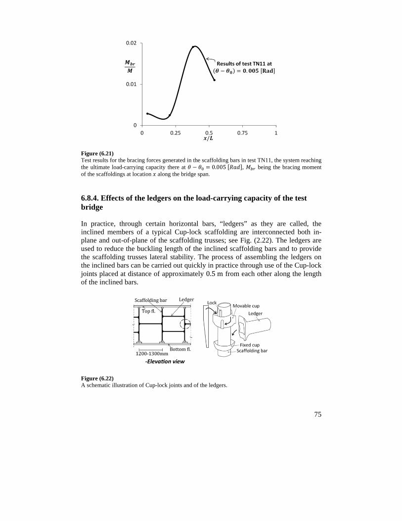
75
Figure (6.21) Test results for the bracing forces generated in the scaffolding bars in test TN11, the system reaching the ultimate load-carrying capacity there at 0.005 , being the bracing moment of the scaffoldings at location along the bridge span.
6.8.4. Effects of the ledgers on the load-carrying capacity of the test bridge
In practice, through certain horizontal bars, “ledgers” as they are called, the inclined members of a typical Cup-lock scaffolding are interconnected both in-plane and out-of-plane of the scaffolding trusses; see Fig. (2.22). The ledgers are used to reduce the buckling length of the inclined scaffolding bars and to provide the scaffolding trusses lateral stability. The process of assembling the ledgers on the inclined bars can be carried out quickly in practice through use of the Cup-lock joints placed at distance of approximately 0.5m from each other along the length of the inclined bars.
Figure (6.22) A schematic illustration of Cup-lock joints and of the ledgers.
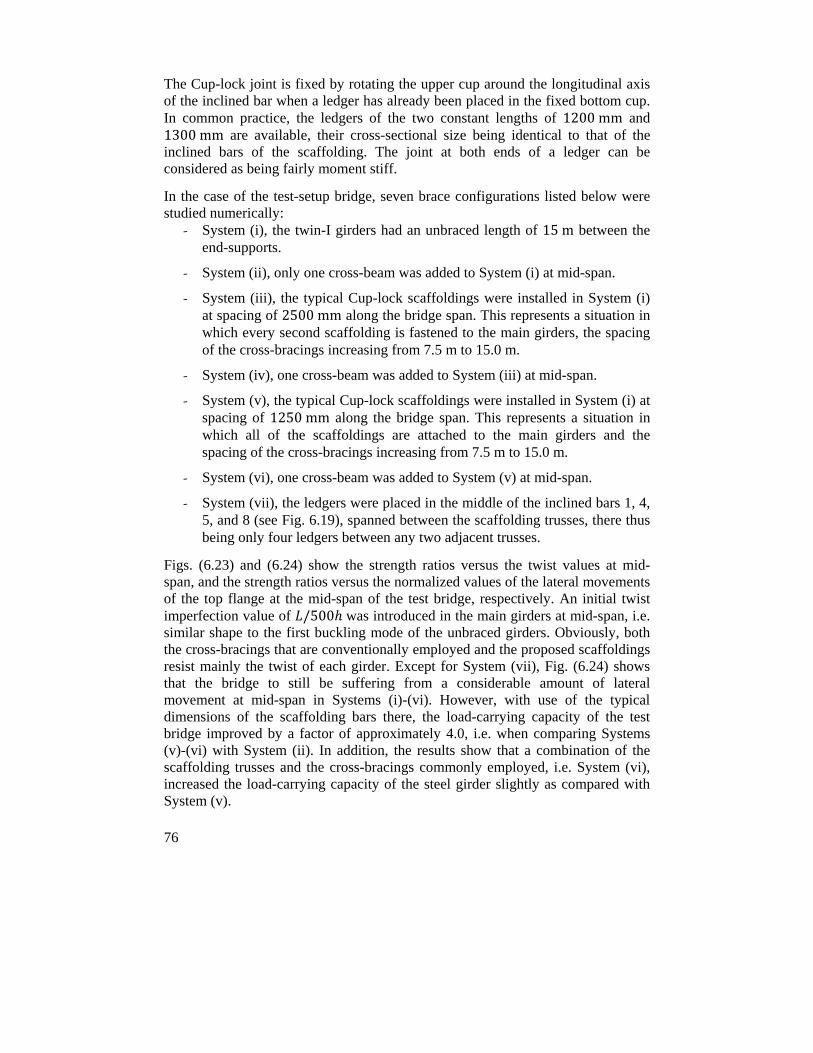
76
The Cup-lock joint is fixed by rotating the upper cup around the longitudinal axis of the inclined bar when a ledger has already been placed in the fixed bottom cup. In common practice, the ledgers of the two constant lengths of 1200mm and 1300mm are available, their cross-sectional size being identical to that of the inclined bars of the scaffolding. The joint at both ends of a ledger can be considered as being fairly moment stiff.
In the case of the test-setup bridge, seven brace configurations listed below were studied numerically:
- System (i), the twin-I girders had an unbraced length of 15m between the end-supports.
- System (ii), only one cross-beam was added to System (i) at mid-span.
- System (iii), the typical Cup-lock scaffoldings were installed in System (i) at spacing of 2500mm along the bridge span. This represents a situation in which every second scaffolding is fastened to the main girders, the spacing of the cross-bracings increasing from 7.5 m to 15.0 m.
- System (iv), one cross-beam was added to System (iii) at mid-span.
- System (v), the typical Cup-lock scaffoldings were installed in System (i) at spacing of 1250mm along the bridge span. This represents a situation in which all of the scaffoldings are attached to the main girders and the spacing of the cross-bracings increasing from 7.5 m to 15.0 m.
- System (vi), one cross-beam was added to System (v) at mid-span.
- System (vii), the ledgers were placed in the middle of the inclined bars 1, 4, 5, and 8 (see Fig. 6.19), spanned between the scaffolding trusses, there thus being only four ledgers between any two adjacent trusses.
Figs. (6.23) and (6.24) show the strength ratios versus the twist values at mid-span, and the strength ratios versus the normalized values of the lateral movements of the top flange at the mid-span of the test bridge, respectively. An initial twist imperfection value of /500 was introduced in the main girders at mid-span, i.e. similar shape to the first buckling mode of the unbraced girders. Obviously, both the cross-bracings that are conventionally employed and the proposed scaffoldings resist mainly the twist of each girder. Except for System (vii), Fig. (6.24) shows that the bridge to still be suffering from a considerable amount of lateral movement at mid-span in Systems (i)-(vi). However, with use of the typical dimensions of the scaffolding bars there, the load-carrying capacity of the test bridge improved by a factor of approximately 4.0, i.e. when comparing Systems (v)-(vi) with System (ii). In addition, the results show that a combination of the scaffolding trusses and the cross-bracings commonly employed, i.e. System (vi), increased the load-carrying capacity of the steel girder slightly as compared with System (v).
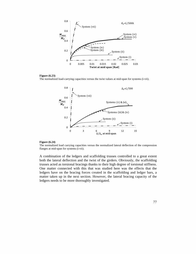
77
Figure (6.23) The normalized load-carrying capacities versus the twist values at mid-span for systems (i-vii).
Figure (6.24) The normalized load carrying capacities versus the normalized lateral deflection of the compression flanges at mid-span for systems (i-vii).
A combination of the ledgers and scaffolding trusses controlled to a great extent both the lateral deflection and the twist of the girders. Obviously, the scaffolding trusses acted as torsional bracings thanks to their high degree of torsional stiffness. One matter connected with this that was studied here was the effects that the ledgers have on the bracing forces created in the scaffolding and ledger bars, a matter taken up in the next section. However, the lateral bracing capacity of the ledgers needs to be more thoroughly investigated.
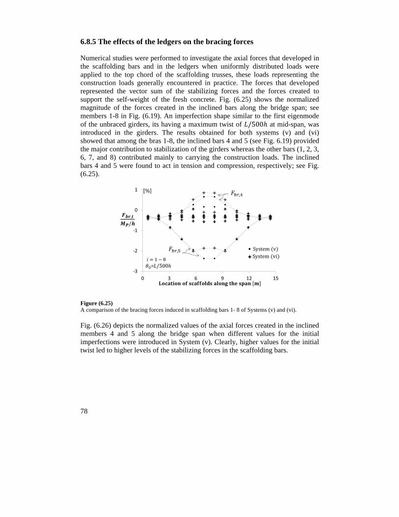
78
6.8.5 The effects of the ledgers on the bracing forces
Numerical studies were performed to investigate the axial forces that developed in the scaffolding bars and in the ledgers when uniformly distributed loads were applied to the top chord of the scaffolding trusses, these loads representing the construction loads generally encountered in practice. The forces that developed represented the vector sum of the stabilizing forces and the forces created to support the self-weight of the fresh concrete. Fig. (6.25) shows the normalized magnitude of the forces created in the inclined bars along the bridge span; see members 1-8 in Fig. (6.19). An imperfection shape similar to the first eigenmode of the unbraced girders, its having a maximum twist of /500 at mid-span, was introduced in the girders. The results obtained for both systems (v) and (vi) showed that among the bras 1-8, the inclined bars 4 and 5 (see Fig. 6.19) provided the major contribution to stabilization of the girders whereas the other bars (1, 2, 3, 6, 7, and 8) contributed mainly to carrying the construction loads. The inclined bars 4 and 5 were found to act in tension and compression, respectively; see Fig. (6.25).
Figure (6.25) A comparison of the bracing forces induced in scaffolding bars 1- 8 of Systems (v) and (vi).
Fig. (6.26) depicts the normalized values of the axial forces created in the inclined members 4 and 5 along the bridge span when different values for the initial imperfections were introduced in System (v). Clearly, higher values for the initial twist led to higher levels of the stabilizing forces in the scaffolding bars.
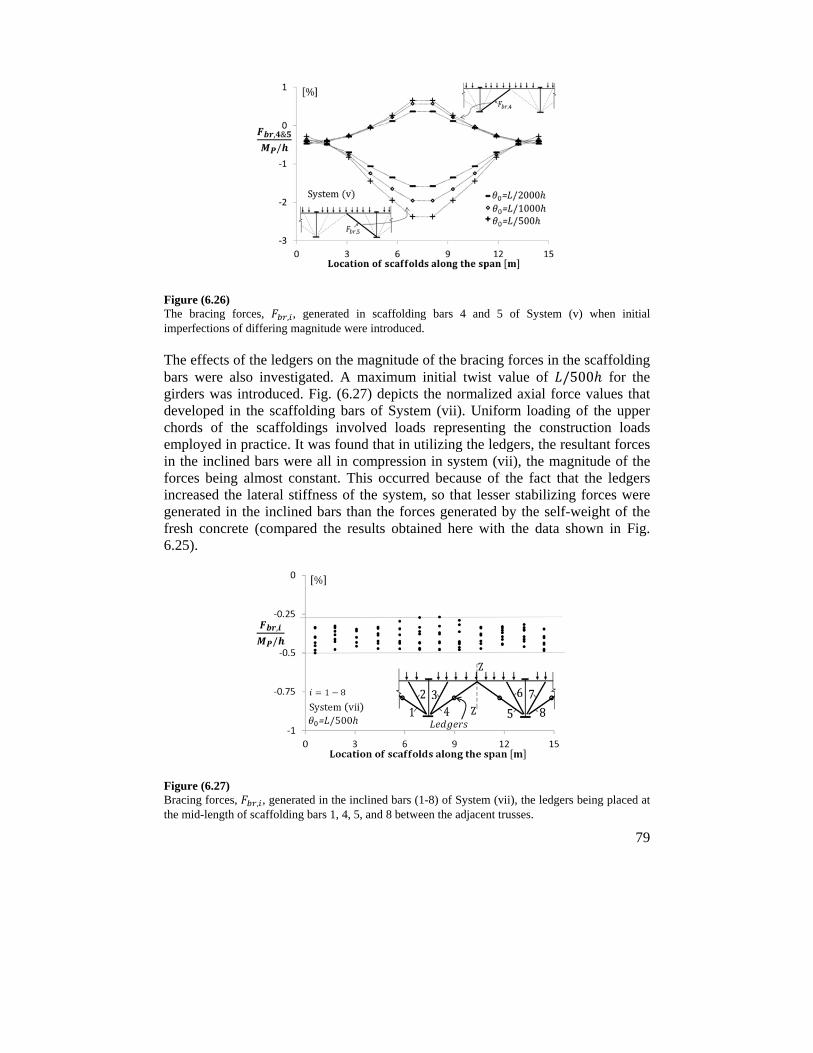
79
Figure (6.26) The bracing forces, , , generated in scaffolding bars 4 and 5 of System (v) when initial imperfections of differing magnitude were introduced.
The effects of the ledgers on the magnitude of the bracing forces in the scaffolding bars were also investigated. A maximum initial twist value of /500 for the girders was introduced. Fig. (6.27) depicts the normalized axial force values that developed in the scaffolding bars of System (vii). Uniform loading of the upper chords of the scaffoldings involved loads representing the construction loads employed in practice. It was found that in utilizing the ledgers, the resultant forces in the inclined bars were all in compression in system (vii), the magnitude of the forces being almost constant. This occurred because of the fact that the ledgers increased the lateral stiffness of the system, so that lesser stabilizing forces were generated in the inclined bars than the forces generated by the self-weight of the fresh concrete (compared the results obtained here with the data shown in Fig. 6.25).
Figure (6.27) Bracing forces, , , generated in the inclined bars (1-8) of System (vii), the ledgers being placed at the mid-length of scaffolding bars 1, 4, 5, and 8 between the adjacent trusses.
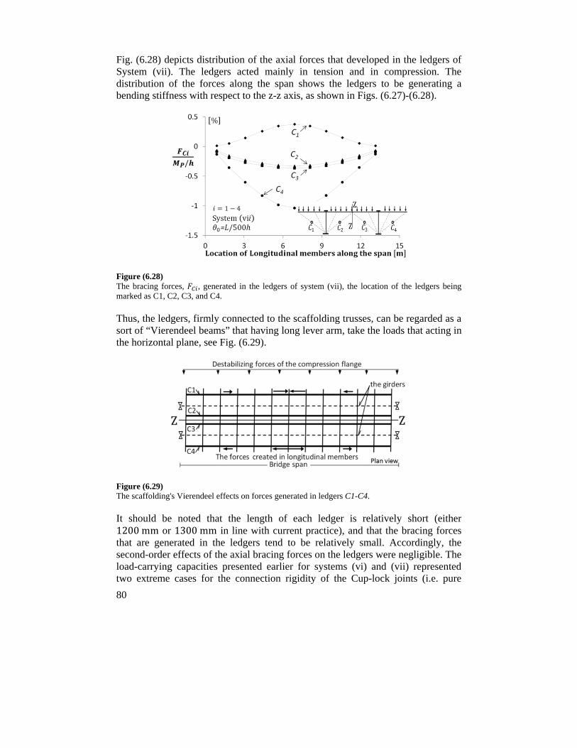
80
Fig. (6.28) depicts distribution of the axial forces that developed in the ledgers of System (vii). The ledgers acted mainly in tension and in compression. The distribution of the forces along the span shows the ledgers to be generating a bending stiffness with respect to the z-z axis, as shown in Figs. (6.27)-(6.28).
Figure (6.28) The bracing forces, , generated in the ledgers of system (vii), the location of the ledgers being marked as C1, C2, C3, and C4.
Thus, the ledgers, firmly connected to the scaffolding trusses, can be regarded as a sort of “Vierendeel beams” that having long lever arm, take the loads that acting in the horizontal plane, see Fig. (6.29).
Figure (6.29) The scaffolding's Vierendeel effects on forces generated in ledgers C1-C4.
It should be noted that the length of each ledger is relatively short (either 1200mm or 1300mm in line with current practice), and that the bracing forces that are generated in the ledgers tend to be relatively small. Accordingly, the second-order effects of the axial bracing forces on the ledgers were negligible. The load-carrying capacities presented earlier for systems (vi) and (vii) represented two extreme cases for the connection rigidity of the Cup-lock joints (i.e. pure
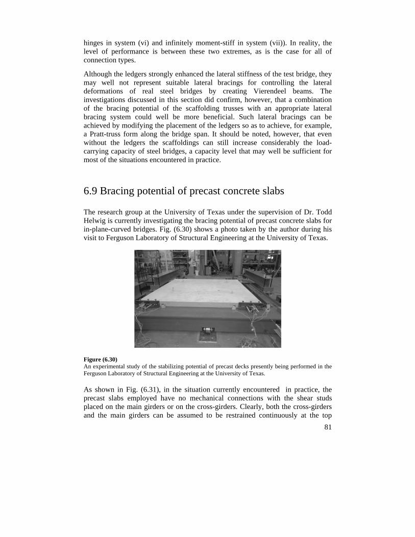
81
hinges in system (vi) and infinitely moment-stiff in system (vii)). In reality, the level of performance is between these two extremes, as is the case for all of connection types.
Although the ledgers strongly enhanced the lateral stiffness of the test bridge, they may well not represent suitable lateral bracings for controlling the lateral deformations of real steel bridges by creating Vierendeel beams. The investigations discussed in this section did confirm, however, that a combination of the bracing potential of the scaffolding trusses with an appropriate lateral bracing system could well be more beneficial. Such lateral bracings can be achieved by modifying the placement of the ledgers so as to achieve, for example, a Pratt-truss form along the bridge span. It should be noted, however, that even without the ledgers the scaffoldings can still increase considerably the load-carrying capacity of steel bridges, a capacity level that may well be sufficient for most of the situations encountered in practice.
6.9 Bracing potential of precast concrete slabs
The research group at the University of Texas under the supervision of Dr. Todd Helwig is currently investigating the bracing potential of precast concrete slabs for in-plane-curved bridges. Fig. (6.30) shows a photo taken by the author during his visit to Ferguson Laboratory of Structural Engineering at the University of Texas.
Figure (6.30) An experimental study of the stabilizing potential of precast decks presently being performed in the Ferguson Laboratory of Structural Engineering at the University of Texas.
As shown in Fig. (6.31), in the situation currently encountered in practice, the precast slabs employed have no mechanical connections with the shear studs placed on the main girders or on the cross-girders. Clearly, both the cross-girders and the main girders can be assumed to be restrained continuously at the top
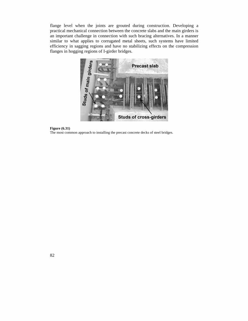
82
flange level when the joints are grouted during construction. Developing a practical mechanical connection between the concrete slabs and the main girders is an important challenge in connection with such bracing alternatives. In a manner similar to what applies to corrugated metal sheets, such systems have limited efficiency in sagging regions and have no stabilizing effects on the compression flanges in hogging regions of I-girder bridges.
Figure (6.31) The most common approach to installing the precast concrete decks of steel bridges.
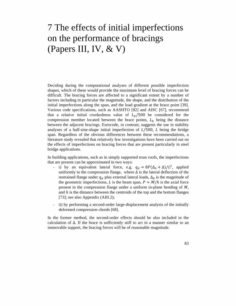
83
7 The effects of initial imperfections on the performance of bracings (Papers III, IV, & V)
Deciding during the computational analyses of different possible imperfection shapes, which of these would provide the maximum level of bracing forces can be difficult. The bracing forces are affected to a significant extent by a number of factors including in particular the magnitude, the shape, and the distribution of the initial imperfections along the span, and the load gradient at the brace point [39]. Various code specifications, such as AASHTO [82] and AISC [67], recommend that a relative initial crookedness value of /500 be considered for the compression member located between the brace points, being the distance between the adjacent bracings. Eurocode, in contrast, suggests the use in stability analyses of a half-sine-shape initial imperfection of /500, being the bridge span. Regardless of the obvious differences between these recommendations, a literature study revealed that relatively few investigations have been carried out on the effects of imperfections on bracing forces that are present particularly in steel bridge applications.
In building applications, such as in simply supported truss roofs, the imperfections that are present can be approximated in two ways:
- i) by an equivalent lateral force, e.g. 8 ∆ ∆ / , applied uniformly to the compression flange, where ∆ is the lateral deflection of the restrained flange under plus external lateral loads, ∆ is the magnitude of the geometric imperfections, is the beam span, / is the axial force present in the compression flange under a uniform in-plane bending of , and is the distance between the centroids of the top and the bottom flanges [73]; see also Appendix (AIII.2);
- ii) by performing a second-order large-displacement analysis of the initially deformed compression chords [68].
In the former method, the second-order effects should be also included in the calculation of ∆. If the brace is sufficiently stiff to act in a manner similar to an immovable support, the bracing forces will be of reasonable magnitude.
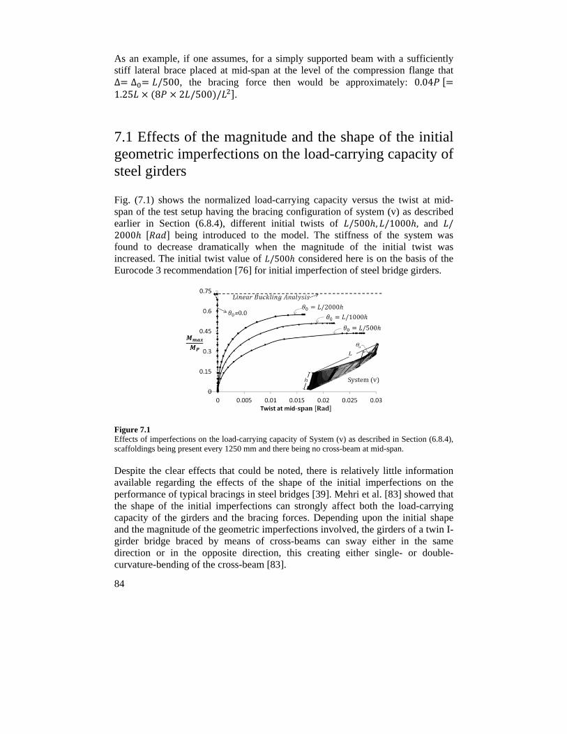
84
As an example, if one assumes, for a simply supported beam with a sufficiently stiff lateral brace placed at mid-span at the level of the compression flange that ∆ ∆ /500, the bracing force then would be approximately: 0.04 1.25 8 2 /500 / .
7.1 Effects of the magnitude and the shape of the initial geometric imperfections on the load-carrying capacity of steel girders
Fig. (7.1) shows the normalized load-carrying capacity versus the twist at mid-span of the test setup having the bracing configuration of system (v) as described earlier in Section (6.8.4), different initial twists of /500 , /1000 , and /2000 being introduced to the model. The stiffness of the system was found to decrease dramatically when the magnitude of the initial twist was increased. The initial twist value of /500 considered here is on the basis of the Eurocode 3 recommendation [76] for initial imperfection of steel bridge girders.
Figure 7.1 Effects of imperfections on the load-carrying capacity of System (v) as described in Section (6.8.4), scaffoldings being present every 1250 mm and there being no cross-beam at mid-span.
Despite the clear effects that could be noted, there is relatively little information available regarding the effects of the shape of the initial imperfections on the performance of typical bracings in steel bridges [39]. Mehri et al. [83] showed that the shape of the initial imperfections can strongly affect both the load-carrying capacity of the girders and the bracing forces. Depending upon the initial shape and the magnitude of the geometric imperfections involved, the girders of a twin I-girder bridge braced by means of cross-beams can sway either in the same direction or in the opposite direction, this creating either single- or double-curvature-bending of the cross-beam [83].
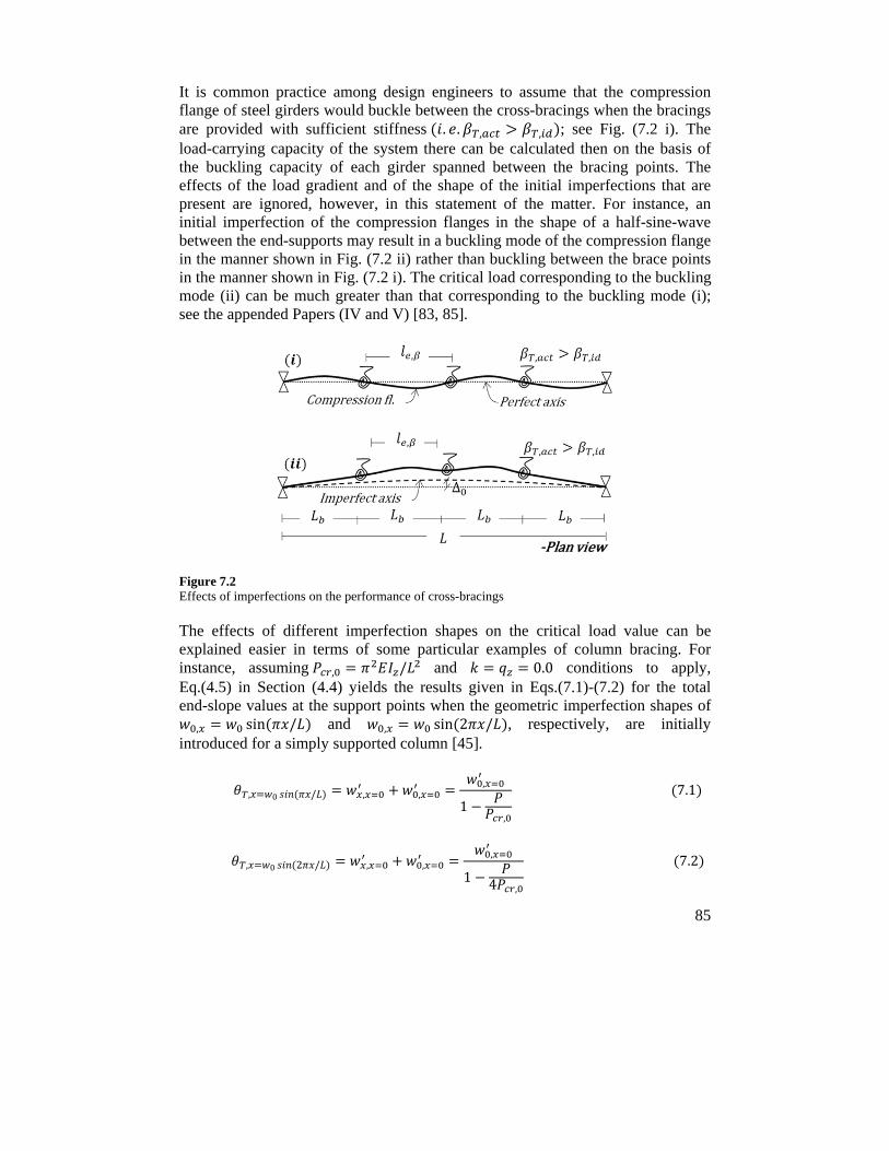
85
It is common practice among design engineers to assume that the compression flange of steel girders would buckle between the cross-bracings when the bracings are provided with sufficient stiffness . . , , ; see Fig. (7.2 i). The load-carrying capacity of the system there can be calculated then on the basis of the buckling capacity of each girder spanned between the bracing points. The effects of the load gradient and of the shape of the initial imperfections that are present are ignored, however, in this statement of the matter. For instance, an initial imperfection of the compression flanges in the shape of a half-sine-wave between the end-supports may result in a buckling mode of the compression flange in the manner shown in Fig. (7.2 ii) rather than buckling between the brace points in the manner shown in Fig. (7.2 i). The critical load corresponding to the buckling mode (ii) can be much greater than that corresponding to the buckling mode (i); see the appended Papers (IV and V) [83, 85].
Figure 7.2 Effects of imperfections on the performance of cross-bracings
The effects of different imperfection shapes on the critical load value can be explained easier in terms of some particular examples of column bracing. For instance, assuming , / and 0.0 conditions to apply, Eq.(4.5) in Section (4.4) yields the results given in Eqs.(7.1)-(7.2) for the total end-slope values at the support points when the geometric imperfection shapes of
, sin / and , sin 2 / , respectively, are initially introduced for a simply supported column [45].
, 0 / , ,,
1,
7.1
, 0 2 / , ,,
1 4 ,
7.2
86
In practice, although a column having a full-sine-shaped imperfection, i.e. , sin 2 / , might never reach a critical load value of 4 ,
corresponding to an S-shape buckling mode, the column might not buckle at a , load level either. Depending on the magnitude of an imperfection, snapping
through from an initial S-shape to a bow shape deformation, and in general a substantial change in the out-of-plane deformation profile, might require much additional strain energy to be consumed. Under such circumstances, a column may reach a load-carrying capacity in excess of the minimum critical load value corresponding to its lowest eigenmode. Of the infinite number of imperfection shapes that are possible, only one can be the same as that of the first eigenmode of a braced system. Although this worst scenario might be relevant in some cases and might possibly occur in practice, its occurrence is very unlikely in most practical situations. For instance in a twin-I girder bridge having a number of intermediate cross-bracings, a sine-wave imperfection shape (a shape similar to the first buckling mode shape) having inflections at the locations of the cross-bracings is very unlikely to occur.
7.2 Effects of the shape and the magnitude of initial geometric imperfections on brace forces
The magnitude of the initial imperfections affects the bracing strength requirements directly. Eq. (7.3) presents a general expression for the relationship between the initial imperfections, ∆ , and the bracing forces, , [1].
∆ ∆0/
1 / 7.3
Where ∆ is the deformation of the compression member at the brace point, and and are the actual (provided value) and the ideal (minimum required
value to act similar to immovable support) stiffness values of the bracing in question.
The bracing force obtained on the basis of Eq. (7.3) can be adjusted by a modification factor of 1 /∆ if any slipping, , also occurs in bracing connections in cases of oversized holes [3].
Investigations reported in Paper (IV) showed initial imperfections to also have a strong effect on the magnitude of bracing forces that develop in the cross-bracings, and often on the load-carrying capacity of slender girders as well. Both tests and FE investigations that were conducted showed the shape of geometric imperfections to have a dominant effect on the distortion of the cross-section of a bridge resulting in either a single-curvature or a reverse-curvature bending of the
87
cross-beam members, regardless of the location of the cross-beam member across the depth of main girders. In investigations of brace forces in the cross-beams of steel bridges, in addition to the half-sine shape between the end-supports currently recommended by Eurocode 3, the study recommends that a similar imperfection shape, but one having an eccentric distribution with its maximum magnitude at a quarter of the bridge span, for example, also be considered in the bracing analyses.

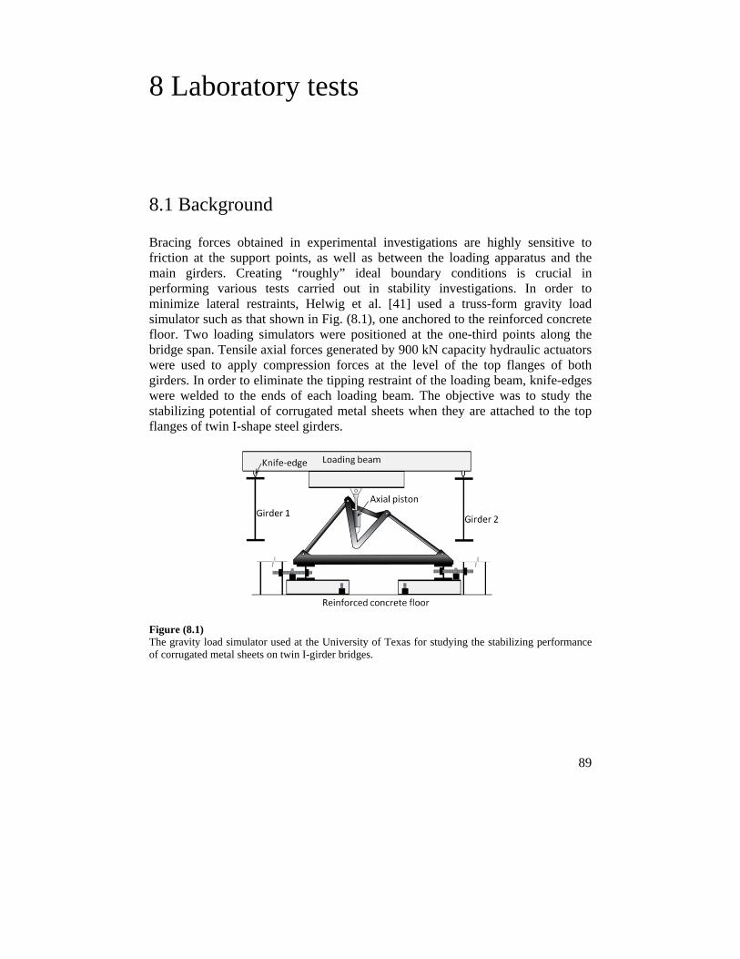
89
8 Laboratory tests
8.1 Background
Bracing forces obtained in experimental investigations are highly sensitive to friction at the support points, as well as between the loading apparatus and the main girders. Creating “roughly” ideal boundary conditions is crucial in performing various tests carried out in stability investigations. In order to minimize lateral restraints, Helwig et al. [41] used a truss-form gravity load simulator such as that shown in Fig. (8.1), one anchored to the reinforced concrete floor. Two loading simulators were positioned at the one-third points along the bridge span. Tensile axial forces generated by 900 kN capacity hydraulic actuators were used to apply compression forces at the level of the top flanges of both girders. In order to eliminate the tipping restraint of the loading beam, knife-edges were welded to the ends of each loading beam. The objective was to study the stabilizing potential of corrugated metal sheets when they are attached to the top flanges of twin I-shape steel girders.
Figure (8.1) The gravity load simulator used at the University of Texas for studying the stabilizing performance of corrugated metal sheets on twin I-girder bridges.
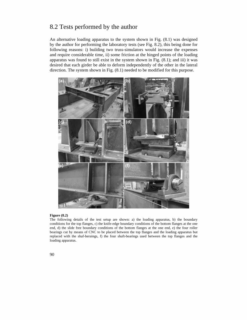
90
8.2 Tests performed by the author
An alternative loading apparatus to the system shown in Fig. (8.1) was designed by the author for performing the laboratory tests (see Fig. 8.2), this being done for following reasons: i) building two truss-simulators would increase the expenses and require considerable time, ii) some friction at the hinged points of the loading apparatus was found to still exist in the system shown in Fig. (8.1); and iii) it was desired that each girder be able to deform independently of the other in the lateral direction. The system shown in Fig. (8.1) needed to be modified for this purpose.
Figure (8.2) The following details of the test setup are shown: a) the loading apparatus, b) the boundary conditions for the top flanges, c) the knife-edge boundary conditions of the bottom flanges at the one end, d) the slide free boundary conditions of the bottom flanges at the one end, e) the four roller bearings cut by means of CNC to be placed between the top flanges and the loading apparatus but replaced with the shaf-beraings, f) the four shaft-bearings used between the top flanges and the loading apparatus.
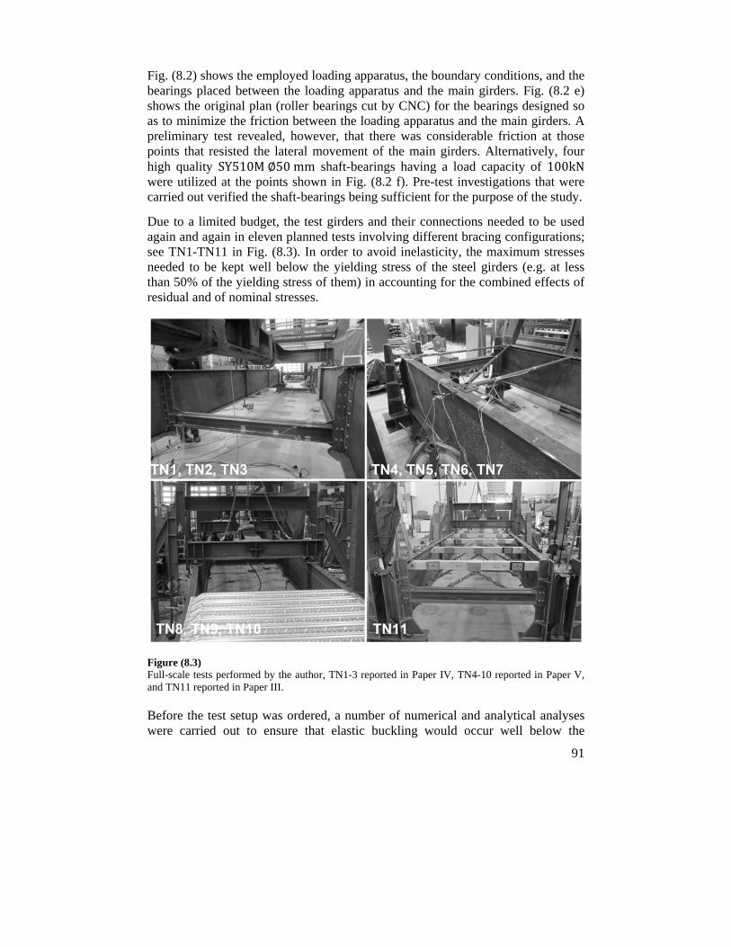
91
Fig. (8.2) shows the employed loading apparatus, the boundary conditions, and the bearings placed between the loading apparatus and the main girders. Fig. (8.2 e) shows the original plan (roller bearings cut by CNC) for the bearings designed so as to minimize the friction between the loading apparatus and the main girders. A preliminary test revealed, however, that there was considerable friction at those points that resisted the lateral movement of the main girders. Alternatively, four high quality SY510M∅50mm shaft-bearings having a load capacity of 100kN were utilized at the points shown in Fig. (8.2 f). Pre-test investigations that were carried out verified the shaft-bearings being sufficient for the purpose of the study.
Due to a limited budget, the test girders and their connections needed to be used again and again in eleven planned tests involving different bracing configurations; see TN1-TN11 in Fig. (8.3). In order to avoid inelasticity, the maximum stresses needed to be kept well below the yielding stress of the steel girders (e.g. at less than 50% of the yielding stress of them) in accounting for the combined effects of residual and of nominal stresses.
Figure (8.3) Full-scale tests performed by the author, TN1-3 reported in Paper IV, TN4-10 reported in Paper V, and TN11 reported in Paper III.
Before the test setup was ordered, a number of numerical and analytical analyses were carried out to ensure that elastic buckling would occur well below the
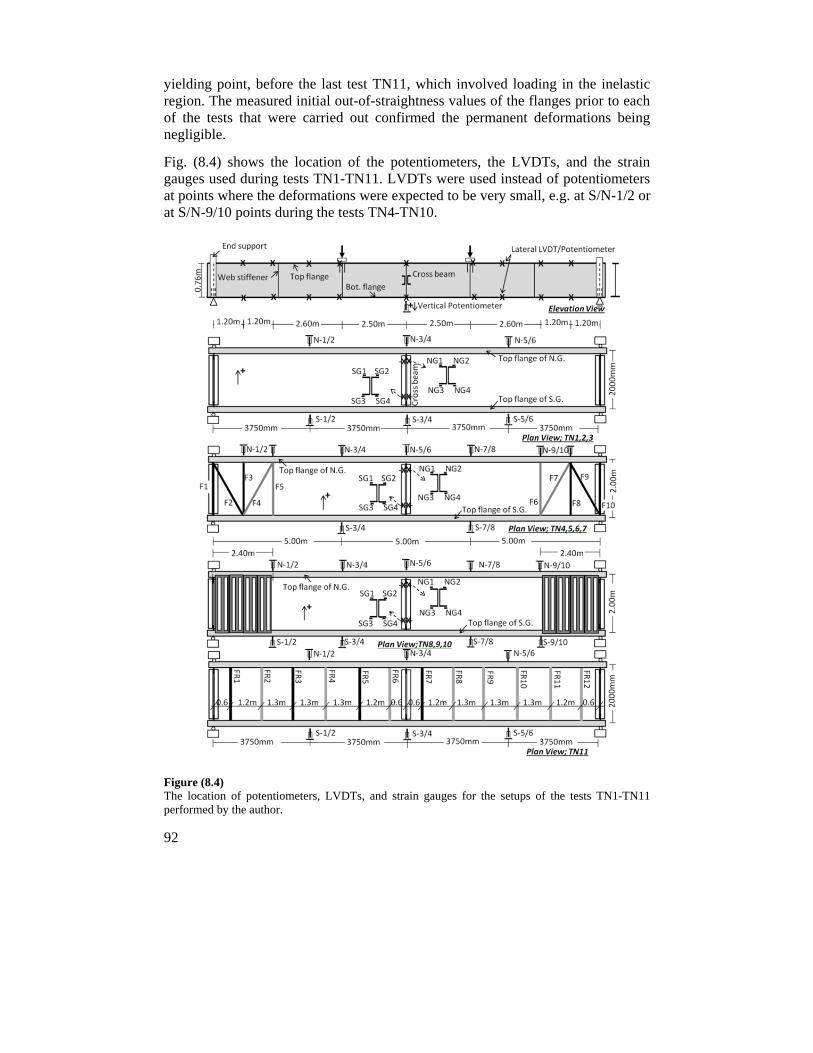
92
yielding point, before the last test TN11, which involved loading in the inelastic region. The measured initial out-of-straightness values of the flanges prior to each of the tests that were carried out confirmed the permanent deformations being negligible.
Fig. (8.4) shows the location of the potentiometers, the LVDTs, and the strain gauges used during tests TN1-TN11. LVDTs were used instead of potentiometers at points where the deformations were expected to be very small, e.g. at S/N-1/2 or at S/N-9/10 points during the tests TN4-TN10.
Figure (8.4) The location of potentiometers, LVDTs, and strain gauges for the setups of the tests TN1-TN11 performed by the author.
93
The potentiometers and the LVDTs employed were"CelescoStingpot300mm0.2mm", "NovotechnikTR100mm, TR50mm 0.05mm", and "Tex0200 0.05mm". Strain gauges were attached to the cross-beams at mid-span (8 gauges: SG/NG1-4), to the truss-bracings (20 gauges: F1-F10), and to the scaffolding bars (32 gauges: FR1, FR3, FR5, FR7) all being the single-direction "Kyowa15mm" type. The loading piston and its maximum capacity was "Enerpac600kN". The loading piston was placed at the center of the H-shape loading apparatus, which was built-up using European standard I beam profiles. The longitudinal beam of the loading apparatus was a 5000mm long IPB330 standard profile type reinforced by 15mm thick steel plates welded onto the topmost surface of the top flange and onto the bottommost surface of the bottom flange. The transversal beams were IPE330. Web stiffeners were welded at the loading point and the shear reaction points.
Further details concerning the test setup are provided in Appendix I.

95
9 Numerical simulations
Performing full-scale experimental investigations can be very expensive. Efforts to create semi-ideal boundary conditions and care in eliminating undesired friction are essential to ensure the usefulness of the structural responses such as in the case of the bracing forces. At the same time, analytical solutions are only possible for relatively simple and limited cases for which a number of assumptions may be required to simplify the problem. The derivation of closed-form solutions in bracing assessments of bridges taking into account various conditions such as those of load-height, asymmetry, cross-sectional variations, imperfections, and the like are very difficult if not impossible to carry out. The simplified methods that are available such as the Grillage analogy for the analysis of bridges require considerable simplifications, and must be repeated for a number of possible buckling mode cases. Human errors can also occur in arriving at assumptions and in the superposition of principals. Simplified methods using the analogy of line-beams on springs can also be valuable and are often suited to particularly common situations. The line-beam models, however, do not consider directly possible transversal effects such as generated by skewed supports, or by radial flange forces in curved bridges. Also, the effects of load-height, and of bracing location across the depth of girders, are difficult to deal with by use of line-beam models. Although initial imperfections can have a substantial effect on the magnitude of bracing forces, the stability analysis of bridges is highly complex when the initial imperfections are included in the analyses. At times, therefore, there is a need of advanced numerical tools for carrying out sophisticated analyses.
Numerical programs are widely available and are relatively easy to use. However, they have the following potential disadvantages:
- The chance of errors is higher,
- It may take longer to set up the model and extract the results,
- The results can only be relied on with greater confidence if the program is used with sufficient practice and with adequate understanding of the modelling assumptions.
- Outputs are highly dependent upon the accuracy of the input data and the mechanical properties that are defined such as the element type and the meshing size,
- More checking is needed.
96
Numerical programs are more vulnerable to human errors if one lacks sufficient practice and understanding. It should be noted, however, that human errors are inevitable regardless of the method employed if personnel involved lack competences. Despite the inherent disadvantages noted above, numerical programs are highly valuable tools when used to initiate ideas or to perform parametric investigations or sensitivity analyses after the model is verified against simplified approaches, experimental data, and analytical solutions. Without doubt, valuable knowledge can be obtained in research with greater confidence in the results by utilizing a combination of the various tools available, including analytical approaches, numerical programs, and laboratory tests.
The commercial software Abaqus [91] was used here mainly for the numerical investigations. Shell elements S4R, were used for modeling webs, flanges, web-stiffeners, and cross-beams since the major portion of the strain energy involved is due to in-plane deformation of the elements. In the case of shell elements, sufficient mesh densities with the aspect ratios close to unity were employed in three directions. The effects of material nonlinearities and large deformations were also taken into account in third-order incremental analyses. Multi-linear material properties were used for steel grade S355 having stress values of 355, 360, 539, and 571 MPa, corresponding to strain values of 0.2, 1.3, 5.5, and 11.3%, and for the S460 steel type with stress values of 460, 466, 561, and 605 MPa, corresponding to strain values of 0.2, 1.2, 4.0, and 11.2%. Top flange uniformly distributed loading was considered in the analyses where applicable, since this is the most common loading condition in practice. However, four-point-flexure loading was considered for modeling when a calibration against test data was being carried out.
Two methods for conducting buckling analyses are available in numerical programs: eigenvalue analysis and incremental analysis. An eigenvalue analysis requires considerably less computational effort since in an incremental analysis the global stiffness matrix becomes updated at each increment. Three different methods for introducing initial geometric imperfections are available: i) performing a linear superposition of buckling mode shapes, ii) using the displacements that take place in a static analysis, and iii) applying displacements to nodes directly. Defining the precise shape of imperfections was not the aim of the study. Imperfections consisting of multiple superimposed buckling-mode shapes regarded as perturbation of the geometry involved were considered in the nonlinear analyses. In use of this approach, two analyses were performed on the same model: a linear buckling analysis of a perfect form of the bridge to determine the buckling modes, and an incremental third-order nonlinear analysis. In the latter analysis, the scaled initial imperfections obtained from the former analysis, were added to the perfect geometry to create a perturbed mesh. Abaqus imports imperfection data in terms of node geometries. Although during the two separate analyses that were performed no compatibility check of the two models carries out
97
by Abaqus, the original model and the subsequent one should be consistent in terms of the assembly, and the node and element numberings, and the like.
To extract nodal information concerning the buckling mode shapes, the following text was added to the input file of the first analysis, the “last mod” being the desired number of eigenmodes to be extracted.
---------------------------------------------------
*Output, field, variable=PRESELECT
*NODE FILE, Global=yes, last mod=1
U
-----------------------------------------------------
To introduce the geometric perturbation to the incremental analyses, a linear superposition of scaled buckling mode shapes was defined. A modification using the text that follows was carried out in the input file of the subsequent analyses. The second and third lines of that text (see below) consist of two values, the first one being the eigenmode number, and the second one the scale factor.
----------------------------------------------------
*Imperfection, File=first job file name, Step=1
1, 15
2,-10
-----------------------------------------------------

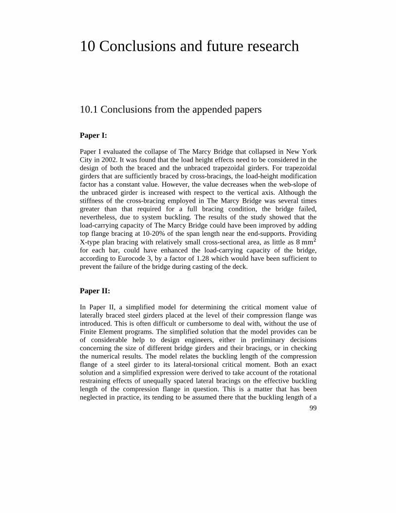
99
10 Conclusions and future research
10.1 Conclusions from the appended papers
Paper I:
Paper I evaluated the collapse of The Marcy Bridge that collapsed in New York City in 2002. It was found that the load height effects need to be considered in the design of both the braced and the unbraced trapezoidal girders. For trapezoidal girders that are sufficiently braced by cross-bracings, the load-height modification factor has a constant value. However, the value decreases when the web-slope of the unbraced girder is increased with respect to the vertical axis. Although the stiffness of the cross-bracing employed in The Marcy Bridge was several times greater than that required for a full bracing condition, the bridge failed, nevertheless, due to system buckling. The results of the study showed that the load-carrying capacity of The Marcy Bridge could have been improved by adding top flange bracing at 10-20% of the span length near the end-supports. Providing X-type plan bracing with relatively small cross-sectional area, as little as 8mm for each bar, could have enhanced the load-carrying capacity of the bridge, according to Eurocode 3, by a factor of 1.28 which would have been sufficient to prevent the failure of the bridge during casting of the deck.
Paper II:
In Paper II, a simplified model for determining the critical moment value of laterally braced steel girders placed at the level of their compression flange was introduced. This is often difficult or cumbersome to deal with, without the use of Finite Element programs. The simplified solution that the model provides can be of considerable help to design engineers, either in preliminary decisions concerning the size of different bridge girders and their bracings, or in checking the numerical results. The model relates the buckling length of the compression flange of a steel girder to its lateral-torsional critical moment. Both an exact solution and a simplified expression were derived to take account of the rotational restraining effects of unequally spaced lateral bracings on the effective buckling length of the compression flange in question. This is a matter that has been neglected in practice, its tending to be assumed there that the buckling length of a
100
compression member is equal to the largest distance between the bracing points. The paper showed that this assumption can give inaccurately unsafe results for very low bracing stiffness values and can at the same time lead to significant overestimation problems for relatively high bracing stiffness values. Typical design curves are presented that can help design engineers considerably in choosing appropriate brace locations and stiffness values without the need of using commercial finite element software for this purpose. The approach can also help one better understand both column and beam bracing and theories concerning them.
Paper III:
Paper III, presents the results of the original study no previous investigation of which appears to have been carried out of the stabilizing potential of one type of scaffolding, so-called “Cup-lock scaffolding”, widely used in the construction of composite bridges in Sweden. Currently, scaffoldings are not considered for use as stabilizing systems in the design of composite bridges, despite the relatively high degree of torsional stiffness they possess. The paper presents the results of full-scale experimental and numerical investigations concerning the torsional bracing performance of such scaffoldings. Minor structural improvements in the scaffoldings were first needed, as discussed in the paper. There was found to be significant bracing potential in the structurally improved scaffoldings when they were installed on bridges of differing dimensions and lateral-torsional slenderness ratios in the numerical investigations. The bracing moments generated in the bars of such scaffoldings were measured. Indications of the bracing forces involved, expressed as a percentage of the maximum in-plane bending moment measured in the main girders, were also provided for design purposes. Since utilizing the bracing potential of such scaffoldings does not substantially increase construction costs, the bridge industry can benefit considerably from taking advantage of the bracing potential of such scaffoldings so as to enhance both the load-carrying capacity and the ductility of bridges during construction.
Paper IV:
Paper IV presents the results of experimental and numerical investigations of the effects of the shape of imperfections on the bracing performance of the typical cross-beams in steel bridges. Three large-scale experimental studies of a twin I-girder bridge were carried out in which the location of the cross-beam across the depth of the main girders was varied at mid-span. In numerical investigations, three bridge structures of differing lateral-torsional slenderness ratio were studied for determining the effects of several different relevant imperfection shapes on the bracing performance of the cross-beams in straight steel bridges. The results
101
obtained showed that the design recommendations currently used can yield unsafe and incorrect predictions of the bracing forces involved. In addition, it was found that slender bridge girders can reach a load-carrying capacity significantly greater than what is predicted theoretically for the critical load value of the braced girders, the extent of this difference depending upon the shape of geometric imperfections present initially in the main girders. Both tests that were carried out and the FE investigations showed the shape of imperfections to also have significant effects on the distortion of the cross-section of the braced bridges, its resulting in either a single-curvature or a reverse-curvature bending of the cross-beams involved regardless of the location of the transversal beam across the depth of the main girders. It was also found that both lateral bending and torsional moment could develop in the cross-beams, their magnitudes being affected in a great extent by the shape of initial imperfections. Since significant warping stresses can develop in the cross-beams of asymmetric cross-section, avoiding such beam profiles in cross-beams is suggested.
Paper V:
Paper V presents the results of seven full-scale laboratory tests of the restraining effects on end-warping of plan bracings and corrugated metal sheets when they were installed near the supports of a twin I-girder bridge. Four tests were performed when single-panel Z-type or double-panel Warren-type bracings were attached on the top flanges near each support. In addition, three tests were performed when typical metal sheets were attached by use of nail fasteners of different arrangements to the top flanges. The bracing forces generated in the truss bars were also measured using a pair of strain gauges attached on each bar. The load-carrying capacity of the bridge was found to be enhanced by a factor of 2.0~3.0 when the girders were provided with such warping restraints of both types. The metal sheets employed there, however, showed significantly larger lateral deflections than the utilized plan bracings did. Relatively small forces were generated in the truss bars in order to achieve these marked improvements in the load-carrying capacity. The brace forces in the employed truss bars were compared with the ones obtained through an approximate method being used frequently by the design engineers for the analysis of such bracings. The results obtained by the approximate method which is suggested also by Eurocode 3 agreed fairly well with some of the brace forces that measured during the tests whereas, the predication gave unsafe results with very large discrepancy for few of bars.
The study showed that such inexpensive modifications could be of valuable benefit to narrow bridges that are prone to system buckling.
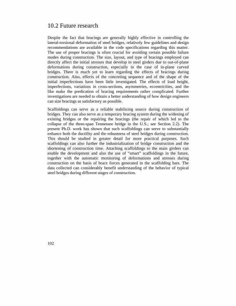
102
10.2 Future research
Despite the fact that bracings are generally highly effective in controlling the lateral-torsional deformation of steel bridges, relatively few guidelines and design recommendations are available in the code specifications regarding this matter. The use of proper bracings is often crucial for avoiding certain possible failure modes during construction. The size, layout, and type of bracings employed can directly affect the initial stresses that develop in steel girders due to out-of-plane deformations during construction, especially in the case of in-plane curved bridges. There is much yet to learn regarding the effects of bracings during construction. Also, effects of the concreting sequence and of the shape of the initial imperfections have been little investigated. The effects of load height, imperfections, variations in cross-sections, asymmetries, eccentricities, and the like make the predication of bracing requirements rather complicated. Further investigations are needed to obtain a better understanding of how design engineers can size bracings as satisfactory as possible.
Scaffoldings can serve as a reliable stabilizing source during construction of bridges. They can also serve as a temporary bracing system during the widening of existing bridges or the repairing the bracings (the repair of which led to the collapse of the three-span Tennessee bridge in the U.S.; see Section 2.2). The present Ph.D. work has shown that such scaffoldings can serve to substantially enhance both the ductility and the robustness of steel bridges during construction. This should be studied in greater detail for more practical purposes. Such scaffoldings can also further the industrialization of bridge construction and the shortening of construction time. Attaching scaffoldings to the main girders can enable the development and also the use of “smart” scaffoldings in the future, together with the automatic monitoring of deformations and stresses during construction on the basis of brace forces generated in the scaffolding bars. The data collected can considerably benefit understanding of the behavior of typical steel bridges during different stages of construction.
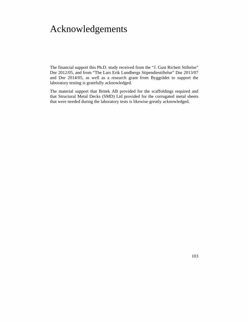
103
Acknowledgements
The financial support this Ph.D. study received from the “J. Gust Richert Stiftelse” Dnr 2012/05, and from “The Lars Erik Lundbergs Stipendiestiftelse” Dnr 2013/07 and Dnr 2014/05, as well as a research grant from Byggrådet to support the laboratory testing is gratefully acknowledged.
The material support that Britek AB provided for the scaffoldings required and that Structural Metal Decks (SMD) Ltd provided for the corrugated metal sheets that were needed during the laboratory tests is likewise greatly acknowledged.

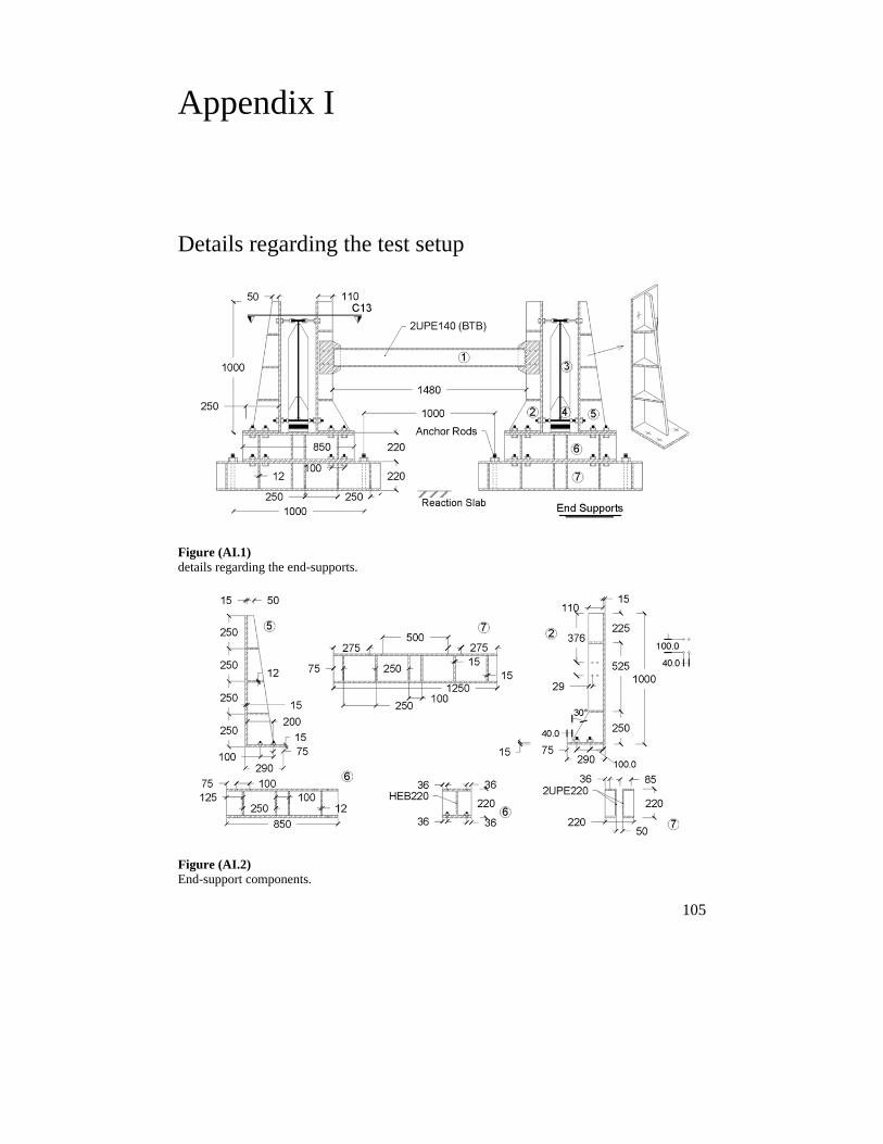
105
Appendix I
Details regarding the test setup
Figure (AI.1) details regarding the end-supports.
Figure (AI.2) End-support components.
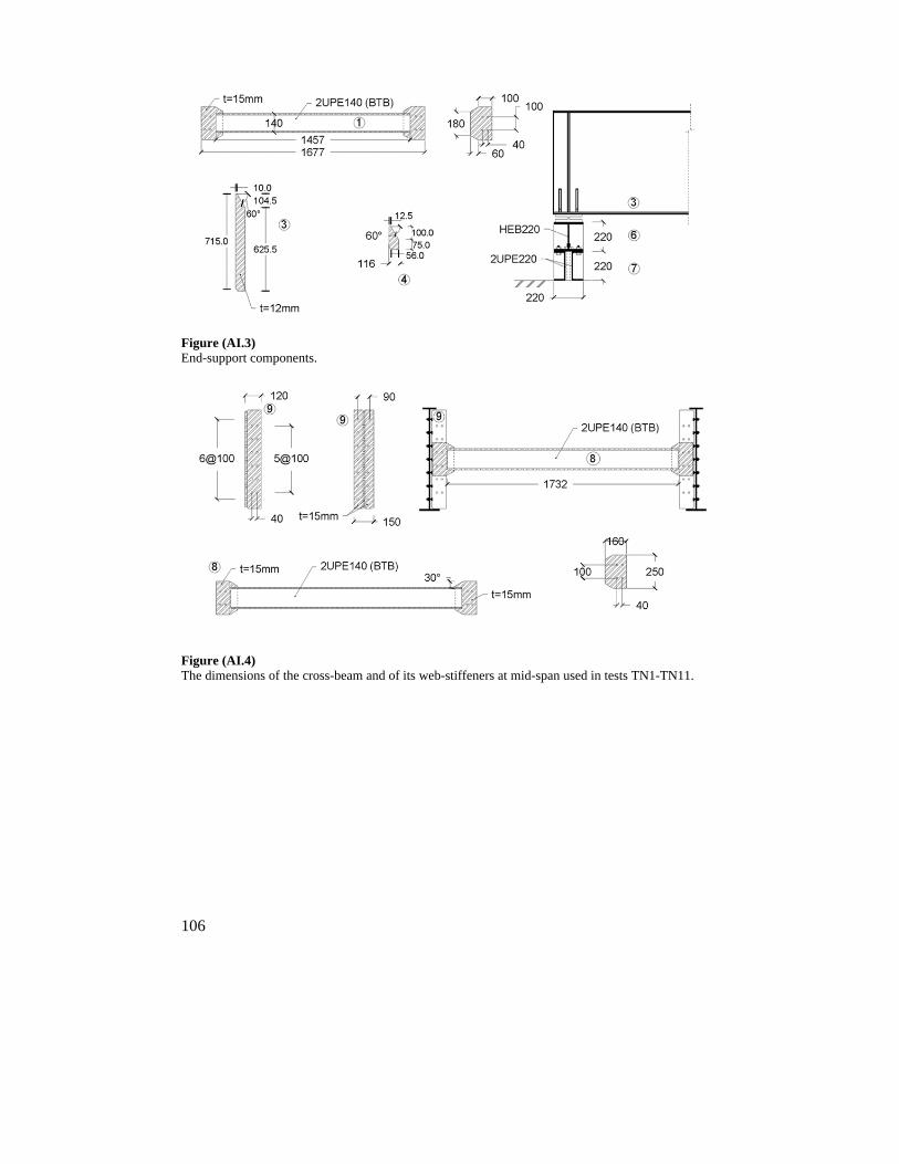
106
Figure (AI.3) End-support components.
Figure (AI.4) The dimensions of the cross-beam and of its web-stiffeners at mid-span used in tests TN1-TN11.
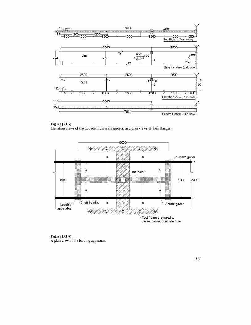
107
Figure (AI.5) Elevation views of the two identical main girders, and plan views of their flanges.
Figure (AI.6) A plan view of the loading apparatus.
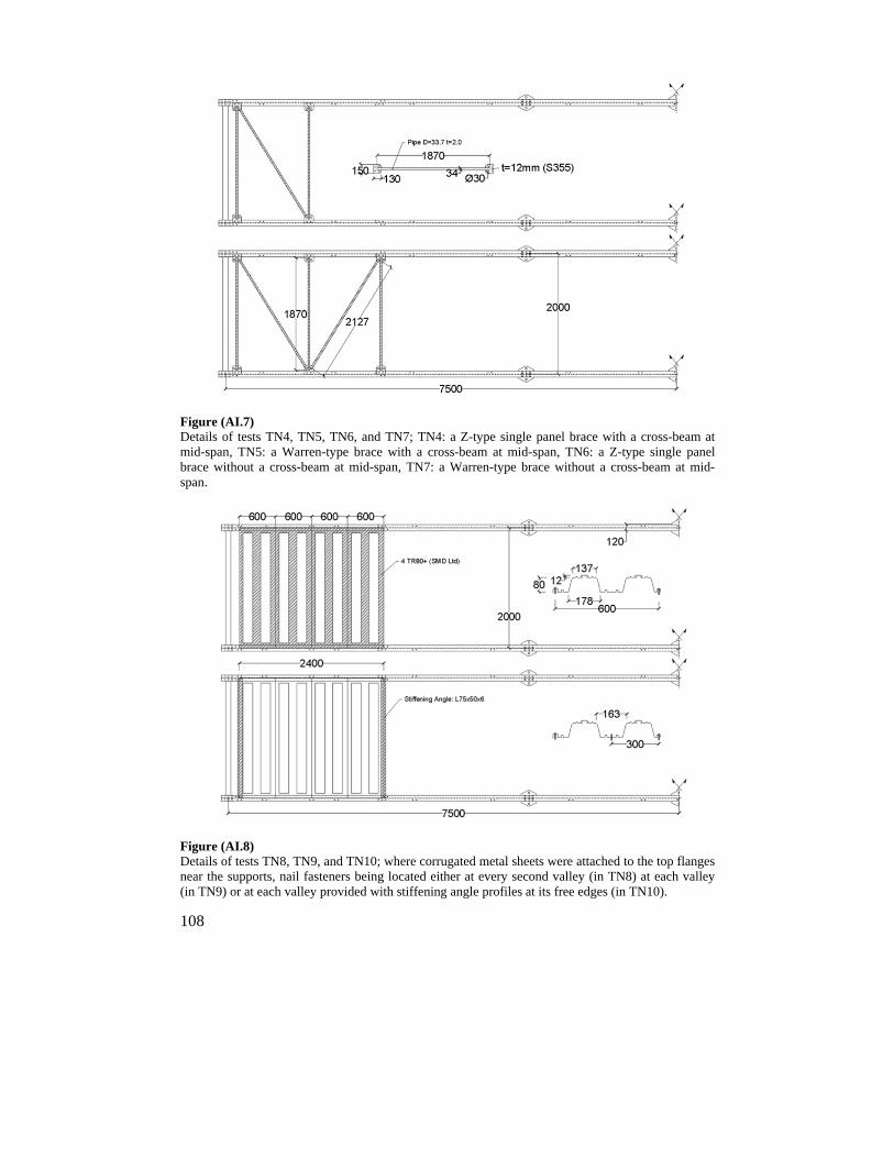
108
Figure (AI.7) Details of tests TN4, TN5, TN6, and TN7; TN4: a Z-type single panel brace with a cross-beam at mid-span, TN5: a Warren-type brace with a cross-beam at mid-span, TN6: a Z-type single panel brace without a cross-beam at mid-span, TN7: a Warren-type brace without a cross-beam at mid-span.
Figure (AI.8) Details of tests TN8, TN9, and TN10; where corrugated metal sheets were attached to the top flanges near the supports, nail fasteners being located either at every second valley (in TN8) at each valley (in TN9) or at each valley provided with stiffening angle profiles at its free edges (in TN10).
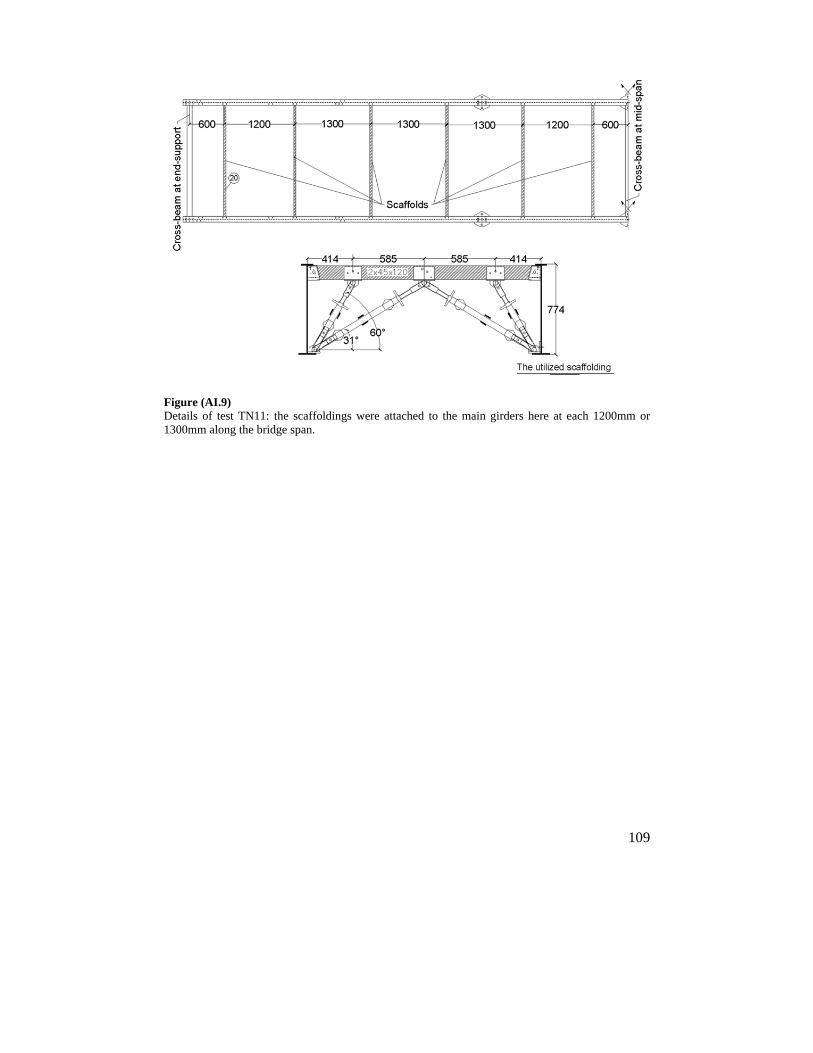
109
Figure (AI.9) Details of test TN11: the scaffoldings were attached to the main girders here at each 1200mm or 1300mm along the bridge span.

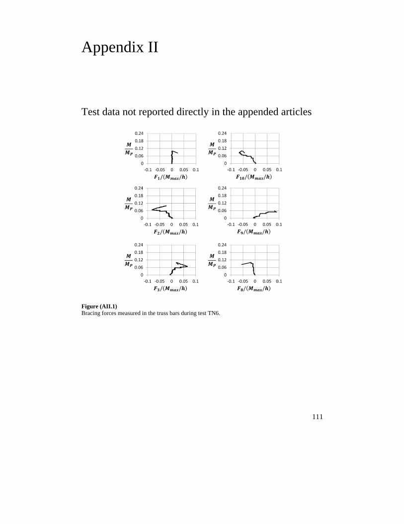
111
Appendix II
Test data not reported directly in the appended articles
Figure (AII.1) Bracing forces measured in the truss bars during test TN6.
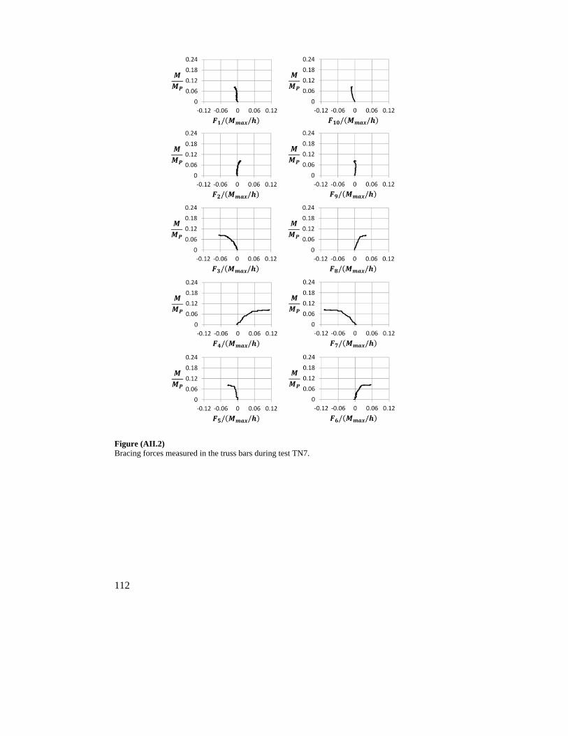
112
Figure (AII.2) Bracing forces measured in the truss bars during test TN7.
113
Appendix III
AIII.1 Bracing analysis; AASHTO recommendations [82]
Summary of the recommendations regarding the use of cross-bracings
The need for cross-bracings shall be investigated both for all stages of the construction procedures and the final conditions that are present, this including but not limiting to the following:
i) the transfer of wind loads between the girders and to the bearings, ii) the stability of the bottom flange in compression, iii) the stability of the top flange in compression prior to the concreting of the deck, and iv) the distribution of the vertical and the live loads that are applied to the bridge.
The cross-bracings for rolled beams and for built-up girders should be as deep as practicable, for rolled beams their being at least half of the beam depth and for built-up girders their being at least 0.75 of the girder depth. Cross-diaphragms having a span-to-depth ratio of greater than 4.0 should be designed as beams. For bridge sections consisting of two or more boxes, external cross-bracings shall be used at end supports. For such systems, the external cross-bracing at the interior supports can only be eliminated if an analysis indicates that the individual boxes are torsionally stable. At the location of external cross-bracings, internal cross-bracings should be also provided.
The cross-bracings should be placed normal to the main girders if the supports are not skewed. They can be placed parallel to the skewed support lines if these are not skewed from normal more than 20 degrees. In such situations, the web-stiffeners should be oriented within the plane of the skewed cross-bracings. When the support lines are skewed from the normal by more than 20 degrees, intermediate cross-bracings shall be placed normal to the girders. The effects of the tangential components of the force transmitted by the skewed end-cross-bracings shall be taken into account when the cross-bracing is skewed. The removal of highly stressed cross-bracings in the vicinity of interior supports that are shewed by more than 20 degrees from the normal, for example, may be beneficial as long as out-of-plane deformation of the girder is not excessive.
114
Where end-supports are skewed by more than 20 degrees from the normal, the first intermediate cross-bracing adjacent to a skewed end-support should be offset by a minimum of 0.4 or 1.5 , being the cross-brace spacing and the girder web depth, this reducing the presence of a stiff-load-path that can attract and transfer large transverse forces to the skewed support.
Cross-bracings shall be spaced along the bridge span in nearly uniform fashion so as to promote constructability and to allow the use of simplified methods of analysis for calculating flange-lateral bending stresses. The requirements for cross-bracings spaced at less than 7.5 m from one another given in previous versions of the AASHTO specifications are replaced here by requirements based on a rational analysis aimed at reducing the presence of fatigue-prone attachment details. The spacing of the intermediate cross-bracings, , in an in-plane curved I-girder bridge shall not exceed /10 , being the girder radius and the limiting unbraced length, which can be determined from / , where is the effective radius of gyration for lateral torsional buckling and the compression-flange stress within the cross-section at the onset of nominal yielding. At a cross-brace spacing greater than , significant lateral flange bending is likely to occur. Intermediate cross-bracings should be placed at or near the in-plane maximum moment in the main girders and near to both sides of the field splices that are present. The need for additional temporary or permanent cross-bracings should be also taken into account in connection with the transportation and the erection of each shipping piece at the lifting points involved.
Summary of the recommendations regarding the use of lateral bracings
Corrugated metal sheets should not be assumed to provide the top flange in compression with adequate stability during concreting of the deck.
Lateral bracings that are not required for the completed state should not be considered as being primary members of the girders in question, and can thus be removed after construction of the bridge is completed. Lateral bracings, if required, should be placed either in or near to the flange that is being restrained. In I-girder bridges having lateral bracings at the level of the bottom flange, a pseudo-closed section can be created together with the hardened concrete deck, this increasing the forces in the cross-beams as they serve to restrain the shape of the closed cross-section.
To reduce the occurrence of large relative lateral movements during construction in the case of I-girder bridges having spans greater than 60m, either temporary or permanent lateral bracings in one or two panels close to the end-supports and near the internal supports when continuous bridges are involved can be considered in the design stage. Although such bracings, when placed at the level of the bottom flanges are about equally effective as compared with those placed at
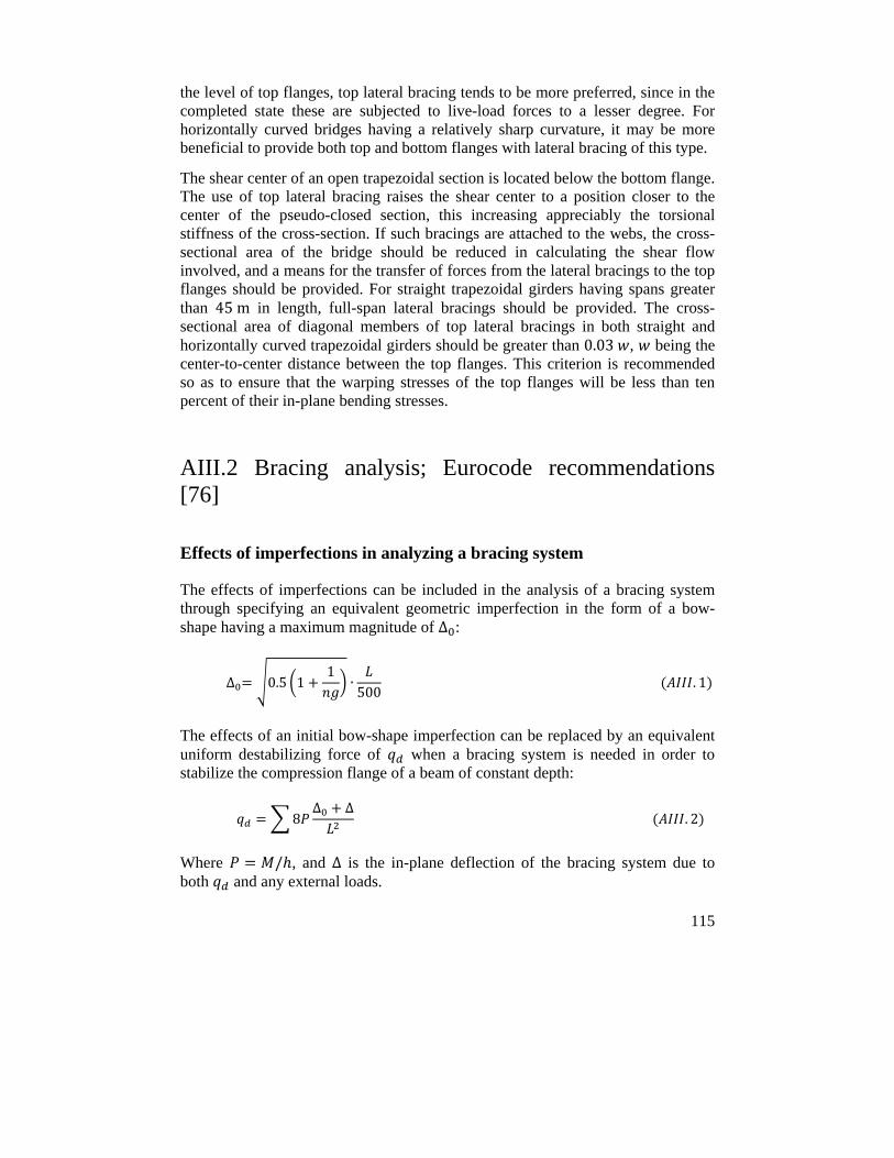
115
the level of top flanges, top lateral bracing tends to be more preferred, since in the completed state these are subjected to live-load forces to a lesser degree. For horizontally curved bridges having a relatively sharp curvature, it may be more beneficial to provide both top and bottom flanges with lateral bracing of this type.
The shear center of an open trapezoidal section is located below the bottom flange. The use of top lateral bracing raises the shear center to a position closer to the center of the pseudo-closed section, this increasing appreciably the torsional stiffness of the cross-section. If such bracings are attached to the webs, the cross-sectional area of the bridge should be reduced in calculating the shear flow involved, and a means for the transfer of forces from the lateral bracings to the top flanges should be provided. For straight trapezoidal girders having spans greater than 45m in length, full-span lateral bracings should be provided. The cross-sectional area of diagonal members of top lateral bracings in both straight and horizontally curved trapezoidal girders should be greater than 0.03 , being the center-to-center distance between the top flanges. This criterion is recommended so as to ensure that the warping stresses of the top flanges will be less than ten percent of their in-plane bending stresses.
AIII.2 Bracing analysis; Eurocode recommendations [76]
Effects of imperfections in analyzing a bracing system
The effects of imperfections can be included in the analysis of a bracing system through specifying an equivalent geometric imperfection in the form of a bow-shape having a maximum magnitude of ∆ :
∆ 0.5 11
∙500
. 1
The effects of an initial bow-shape imperfection can be replaced by an equivalent uniform destabilizing force of when a bracing system is needed in order to stabilize the compression flange of a beam of constant depth:
8∆ ∆
. 2
Where / , and ∆ is the in-plane deflection of the bracing system due to both and any external loads.
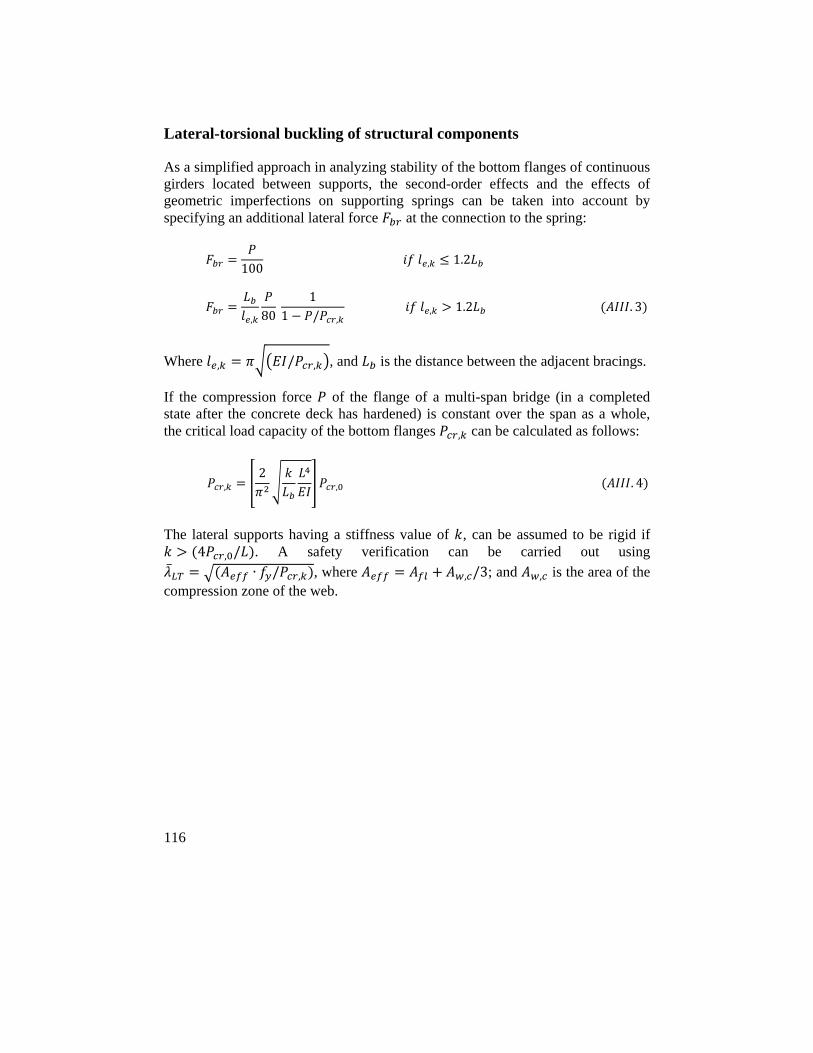
116
Lateral-torsional buckling of structural components
As a simplified approach in analyzing stability of the bottom flanges of continuous girders located between supports, the second-order effects and the effects of geometric imperfections on supporting springs can be taken into account by specifying an additional lateral force at the connection to the spring:
100 , 1.2
, 80
11 / ,
, 1.2 . 3
Where , / , , and is the distance between the adjacent bracings.
If the compression force of the flange of a multi-span bridge (in a completed state after the concrete deck has hardened) is constant over the span as a whole, the critical load capacity of the bottom flanges , can be calculated as follows:
,2
, . 4
The lateral supports having a stiffness value of , can be assumed to be rigid if 4 , / . A safety verification can be carried out using
∙ / , , where , /3; and , is the area of the compression zone of the web.
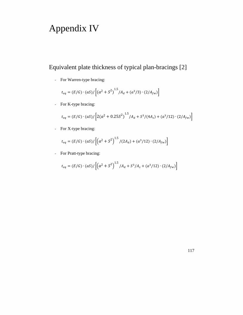
117
Appendix IV
Equivalent plate thickness of typical plan-bracings [2]
- For Warren-type bracing:
/ ∙ / 2 2 1.5/ /3 ∙ 2/
- For K-type bracing:
/ ∙ / 2 2 0.25 2 1.5/ / 4 /12 ∙ 2/
- For X-type bracing:
/ ∙ / 2 2 1.5/ 2 /12 ∙ 2/
- For Pratt-type bracing:
/ ∙ / 2 2 1.5/ / /12 ∙ 2/

119
References
The main references used in the context of the thesis are listed below: [1] G. Winter, "Lateral bracing of columns and beams." vol. Vol. 125, No. 1, , ed:
ASCE, 1960, pp. 807-826 [2] C. F. K. K. Basler, Torsion in structures an engineering approach. Springer-
Verlag: Berlin, New York, 1969. [3] T. Helwig and J. A. Yura, "Steel bridge design handbook: bracing system design,"
U.S. Department of Transportation, Federal Highway Adminstration, Washington, D.C. FHWA-IF-12-052, 2012.
[4] J. A. Yura, "Fundamentals of beam bracing," Engineering Journal, pp. 11-26, 2001.
[5] S. Mamazizi, R. Crocetti, and H. Mehri, "Numerical and experimental investigation on the post-buckling behavior of steel plate girders subjected to shear," presented at the Annual Stability Conference, SSRC 2013, St. Louis, Missouri, 2013.
[6] A. Al-rubaye, "Theoretical and numerical approach to calculate the shear stiffness of corrugated metal decks," M. Sc., Structural Engineering, Lund University, 2014.
[7] A. Winge, "Temporary formworks as torsional bracing system for stee-concrete composite bridges during concreting of the deck," M. Sc., Structural Engineering, Lund University, 2014.
[8] O. Carlson and L. Jaskiewicz, "The performance of conventional discrete torsional bracings in steel-concrete composite bridges: a survey of Swedish bridges," M. Sc., Structural Engineering, Lund University, 2015.
[9] E. Ohlin, "Metal deck forms as lateral bracing of composite bridges with trapezoidal cross-sections," M. Sc., Structural Engineering, Lund University, 2015.
[10] J. Scheer and L. Wilharm, Failed Bridges: Case Studies, Causes and Consequences: Wiley, 2011.
[11] H. Mehri and R. Crocetti, "Scaffolding bracing of composite bridges during construction " Journal of bridge Engineering (ASCE), vol. DOI:10.1061/(ASCE)BE.1943-5592.0000829, 2015.
[12] G. Pincus, "On the lateral support of inelastic columns," AISC Engineering Journal, vol. 1, pp. 113-115, 1964.
[13] N. S. Trahair and S. Kitipornchai, "Elastic lateral buckling of stepped I- beams," ASCE J Struct Div, vol. 97, pp. p 2535-48, 1971.
120
[14] M. A. Serna, A. López, I. Puente, and D. J. Yong, "Equivalent uniform moment factors for lateral–torsional buckling of steel members," Journal of Constructional Steel Research, vol. 62, pp. 566-580, 2006.
[15] J. A. Yura, "Winter's bracing approach revisited," Engineering Structures, vol. 18, pp. 821-825, 1996.
[16] C. M. Wang, S. Kitipornchai, and V. Thevendran, "Buckling of braced monosymmetric cantilevers," International Journal of Mechanical Sciences, vol. 29, pp. 321-337, 1987.
[17] C. M. Wang, C. J. Goh, and E. P. Chew, "AN ENERGY APPROACH TO ELASTIC STABILITY ANALYSIS OF MULTIPLY BRACED MONOSYMMETRIC I-BEAMS," Mechanics of Structures and Machines, vol. 17, pp. 415-429, 1989.
[18] C. M. Wang, K. K. Ang, and L. Wang, "Optimization of bracing and internal support locations for beams against lateral buckling," Structural and Multidisciplinary Optimization, vol. 9, pp. 12-17, 1995.
[19] Z. Vrcelj and M. A. Bradford, "Elastic distortional buckling of continuously restrained I-section beam–columns," Journal of Constructional Steel Research, vol. 62, pp. 223-230, 2006.
[20] J. Valentino and N. S. Trahair, "Torsional restraint against elastic lateral buckling," Journal of Structural Engineering-Asce, vol. 124, pp. 1217-1225, Oct 1998.
[21] J. Valentino, Y. L. Pi, and N. S. Trahair, "Inelastic buckling of steel beams with central torsional restraints," Journal of Structural Engineering, vol. 123, pp. 1180-1186, 1997.
[22] G. S. Tong and S. F. Chen, "Buckling of laterally and torsionally braced beams," Journal of Constructional Steel Research, vol. 11, pp. 41-55, 1988/01/01 1988.
[23] Y. L. Pi and N. S. Trahair, "Nonlinear inelastic analysis of steel beam-columns, II: Applications," Journal of Structural Engineering-Asce, vol. 120, pp. 2062-2085, Jul 1994.
[24] J. A. Yura and G. Li, "Bracing Requirements for Inelastic Beams," in 2002 SSRC Annual Stability Conference, 2002.
[25] Y. C. Wang and D. A. Nethercot, "Bracing requirements for laterally unrestrained beams," Journal of Constructional Steel Research, vol. 17, pp. 305-315, 1990.
[26] T. A. Helwig, J. A. Yura, and K. H. Frank, "Bracing forces in diaphragms and cross frames," in Structural Stability Research Council Conference, April, 1993, pp. 6-7.
[27] Q. H. Zhao, B. L. Yu, and E. G. Burdette, "Effects of cross-frame on stability of double I-girder system under erection," Transportation Research Record, pp. 57-62, 2010.
[28] Q. Zhao, B. Yu, E. G. Burdette, and J. S. Hastings, "Monitoring steel girder stability for safer bridge erection," J. of Performance of Constructed Facilities, vol. 23, pp. 391-398, 2009.
[29] J. S. Park, J. M. Stallings, and Y. J. Kang, "Lateral torsional buckling of prismatic beams with continuous top-flange bracing," Journal of Constructional Steel Research, vol. 60, pp. 147-160, 2004.
[30] B. Kozy and S. Tunstall, "Stability analysis and bracing for system buckling in twin I-girder bridges," Bridge Structures - Assessment, Design & Construction, vol. 3, pp. 149-163, 2007.
121
[31] T. Helwig and J. A. Yura, "Shear diaphragm bracing of beams, II: design requirements," Journal of Structural Engineering, vol. 134, pp. 357-363, 2008.
[32] T. Helwig and J. A. Yura, "Shear diaphragm bracing of beams, I: stiffness and strength behavior," Journal of Structural Engineering, vol. 134, pp. 348-356, 2008.
[33] T. Helwig and K. Frank, "Stiffness Requirements for Diaphragm Bracing of Beams," Journal of Structural Engineering, vol. 125, pp. 1249-1256, 1999.
[34] J. S. Davidson, M. A. Keller, and C. H. Yoo, "Cross-frame spacing and parametric effects in horizontally curved I-girder bridges," Journal of Structural Engineering-Asce, vol. 122, pp. 1089-1096, Sep 1996.
[35] L. Q. Wang and T. Helwig, "Stability bracing requirements for steel bridge girders with skewed supports," Journal of Bridge Engineering, vol. 13, pp. 149-157, Mar-Apr 2008.
[36] C. Topkaya, Widianto, and E. B. Williamson, "Evaluation of top flange bracing systems for curved box girders," Journal of Bridge Engineering, vol. 10, pp. 693-703, 2005.
[37] J. A. Yura, T. Helwig, R. Herman, and C. Zhou, "Global lateral buckling of I-shaped girder systems," Journal of Structural Engineering, vol. 134, pp. 1487-1494, 2008.
[38] Z. Fan and T. A. Helwig, "Behavior of steel box girders with top flange bracing," Journal of Structural Engineering, vol. 125, pp. 829-837, 1999.
[39] L. Wang and T. A. Helwig, "Critical imperfections for beam bracing systems," Journal of Structural Engineering, vol. 131, pp. 933-940, 2005.
[40] J. A. Yura, B. Phillips, S. Raju, and S. Webb, Bracing of steel beams in bridges: Center for Transportation Research, Bureau of Engineering Research, University of Texas at Austin, 1992.
[41] O. Egilmez, T. Helwig, and R. Herman, "Buckling behavior of steel bridge I-girders braced by permanent metal deck forms," J. of Bridge Eng., vol. 17, pp. 624-633, 2012.
[42] O. Egilmez, R. Herman, and T. Helwig, "Lateral Stiffness of Steel Bridge I-Girders Braced by Metal Deck Forms," Journal of Bridge Engineering, vol. 14, pp. 17-25, 2009.
[43] O. Egilmez, T. Helwig, C. Jetann, and R. Lowery, "Stiffness and strength of metal bridge deck forms," Journal of Bridge Engineering, vol. 12, pp. 429-437, 2007.
[44] B. H. Choi, Y. S. Park, and T. y. Yoon, "Experimental study on the ultimate bending resistance of steel tube girders with top lateral bracing," Engineering Structures, vol. 30, pp. 3095-3104, 2008.
[45] T. V. Galambos and A. E. Surovek, Structural stability of steel: concepts and applications for structural engineers: John Wiley & Sons, 2008.
[46] R. Tremblay and D. Mitchell, "Collapse during construction of a precast girder bridge," Journal of Performance of Constructed Facilities, 2006.
[47] B. Åkesson, Plate buckling in bridges and other structures: CRC Press, 2007. [48] J. Leib. (2006, 21 March 2006). A series of deadly errors. Available:
http://www.denverpost.com/news/ci_3622757 [49] H. Mehri and R. Crocetti, "Bracing of steel-concrete composite bridge during
casting of the deck," presented at the Nordic Steel Construction Conference 2012, Oslo, Norway 2012.
[50] EdmontonJournal. (2015, 19 July 2015). Lack of bracing caused 102nd Avenue Bridge girders to buckle. Available: http://www.edmontonjournal.com
122
[51] L. D. Luttrell, "diaphragm design manual," ed: Steel Deck Institute 1981. [52] ECCS, "European recommendations for the application of metal sheeting acting
as a diaphragm," in ECCS publication, ed, 1995. [53] J. André, R. Beale, and A. M. Baptista, "A survey of failures of bridge falsework
systems since 1970," Proceedings of the ICE-Forensic Engineering, vol. 165, pp. 161-172, 2012.
[54] J. F. Bell, The experimental foundations of solid mechanics: Springer, 1984. [55] B. G. Johnston, "Column buckling theory: historic highlights," Journal of
Structural Engineering, vol. 109, pp. 2086-2096, 1983. [56] J. P. Den Hartog, Strength of Materials: Dover publications Incorporated, 1949. [57] S. Timoshenko and G. H. MacCullough, Elements of strength of materials. New
York: D. Van Nostrand Company, Inc., 1935. [58] H. Gil and J. A. Yura, "Bracing requirements of inelastic columns," Journal of
Constructional Steel Research, vol. 51, pp. 1-19, 1999. [59] S. Timoshenko and J. M. Gere, Theory of elastic stability. New York: McGraw-
Hill, 1961. [60] V. Z. Vlasov, Thin-walled elastic beams 2. ed., rev. and augmen. ed. Jerusalem:
Israel Program for Scientific Translations, 1961. [61] R. D. Ziemian, Guide to stability design criteria for metal structures 6th Ed., 6
ed. Hoboken, New Jersey: John Wiley & Sons, 2010. [62] M. G. Salvadori, "Lateral buckling of I-beams," Transactions of the American
Society of Civil Engineers, vol. 120, pp. 1165-1177, 1955. [63] P. Kirby and D. A. Nethercot, Design for structural stability: Halsted Press, 1979. [64] D. A. Nethercot and K. C. Rockey, "Unified approach to elastic lateral buckling
of beams," Engineering Journal, American Institute of Steel Construction Inc, vol. 9, pp. 96-107, 1972.
[65] G. Powell and R. Klingner, "Elastic lateral buckling of steel beams," Journal of Structural Division, 1970.
[66] T. V. Galambos, Guide to stability design criteria for metal structures 5th Ed., 5th ed.: John Wiley & Sons, 1998.
[67] AISC, "Specification for structural steel buildings," vol. ANSI/ AISC 360-10, ed. Chicago, Illinois, 2010.
[68] SCI, Stability of steel beams and columns, in accordance with Eurocodes and the UK National Annexes vol. SCI P360. UK, 2011.
[69] H. Mehri, R. Crocetti, and P. J. Gustafsson, "Unequally spaced lateral bracings on compression flanges of steel girders," Structures, vol. 3, DOI:10.1016/j.istruc.2015.05.003, pp. 236-243, 2015.
[70] S. Kitipornchai and N. S. Trahair, "Buckling properties of monosymmetric I-beams," Department of Civil Engineering, University of Queensland1979.
[71] N. S. Trahair, "Inelastic buckling design of monosymmetric I-beams," Engineering Structures, vol. 34, pp. 564-571, 2012.
[72] Y. L. Pi and N. S. Trahair, "Nonlinear inelastic analysis of steel beam-columns, I:Theory," Journal of Structural Engineering-Asce, vol. 120, pp. 2041-2061, Jul 1994.
[73] EC3, "Design of steel structures –Part 1-1: General rules and rules for buildings," in EN 1993-1-1:2005, ed. Stockholm, Sweden: Swedish Standards Institute, 2005.
[74] J. A. Yura, "Bracing for stability, state-of-the-art," in Proceedings of the 13th Structures Congress. Part 1 (of 2), April 3, 1995 - April 5, 1995, Boston, MA, USA, 1995, pp. 88-103.
123
[75] A. C. Taylor and M. Ojalvo, "Torsional restraint of lateral buckling," J. of the struct. Div., vol. 92, pp. 115-130, 1966.
[76] EC3, "Design of steel structures –Part 2: Steel bridges," in SS-EN 1993-2:2006 ed. Stockholm, Sweden: Swedish Standards Institute, 2009.
[77] P.-O. Thomasson, "lateral-torsional instability of box girder bridges at erection," in International Association for Bridge and Structural Engineering (IABSE), 2008, pp. 414-415.
[78] C. Quadrato, W. Wang, A. Battistini, A. Wahr, T. Helwig, K. Frank, and M. Engelhardt, "Cross-Frame Connection Details for Skewed Steel Bridges," The University of Texas at Austin FHWA/TX-11/0-5701-1, 2010.
[79] Z. Fan and T. Helwig, "Distortional loads and brace forces in steel box girders," J. of Struct.Eng., vol. 128, pp. 710-718, 2002.
[80] T. Helwig, J. A. Yura, R. Herman, E. Williamson, and D. Li, "Design guidelines for steel trapezoidal box girder systems," Univ. of Texas at Austin, Center for Transportation Research FHWA/TX-07/0-4307-1, 2007.
[81] B. J. Bell and D. G. Linzell, "Erection procedure effects on deformations and stresses in a large-radius, horizontally curved, I-girder bridge," Journal of Bridge Engineering, vol. 12, pp. 467-476, 2007.
[82] AASHTO, "AASHTO LRFD Bridge Design Specifications, 7th Ed.," ed. Washington, D. C.: American Association of State Highway and Transportation Officials 2014.
[83] H. Mehri, R. Crocetti, and J. A. Yura, "Effects of geometric imperfections on bracing performance of cross-beams during construction of composite bridges," Engineering Structures, Submitted on 19 July 2015.
[84] SCI, Steel bridge group: guidance notes on best practice in steel bridge construction, 5th issue. UK: The Steel Construction Instutute, 2010.
[85] H. Mehri and R. Crocetti, "End-warping bracing of steel bridges during construction," Journal of bridge Engineering (ASCE), 2015.
[86] J. A. Yura and J. A. Widianto, "Lateral buckling and bracing of beams, a re-evaluation after the Marcy Bridge collapse," in Structural Stability Research Council - 2005 Annual Stability Conference, Apr 6 - 9 2005, Montreal, QB, Canada, 2005, pp. 277-294.
[87] M. M. Attard, "General non-dimensional equation for lateral buckling," Thin-Walled Structures, vol. 9, pp. 417-435, 1990.
[88] K. Kim and C. H. Yoo, "Effects of external bracing on horizontally curved box girder bridges during construction," Engineering Structures, vol. 28, pp. 1650-1657, 2006.
[89] T. Helwig, O. Egilmez, and C. Jetann, "Lateral bracing of bridge girders by permanent metal deck forms," Texas Department of Transportation, Austin2005.
[90] S. J. Errera and T. V. S. R. Apparao, "Design of I-shaped beams with diaphragm bracing," vol. 102, pp. 769-781, 1976.
[91] ABAQUS/CAE, V 6.13 [computer software]: RI, Simulia., 2013.