For Two Steel Bridges - RHC Engineering Load Rating.pdfFor Two Steel Bridges Jing juan Li PHD, PE,...
24
Load Rating For Two Steel Bridges Jing juan Li PHD, PE, SE Senior Project Manager RHC ENGINEERING September 2013
Transcript of For Two Steel Bridges - RHC Engineering Load Rating.pdfFor Two Steel Bridges Jing juan Li PHD, PE,...
Load Rating
For Two Steel Bridges
Jing juan Li
PHD, PE, SE
Senior Project Manager
RHC ENGINEERING
September 2013

Project Introduction
Jing Juan Li, PHD, PE, SE
RHC ENGINEERING
www.rhcengineering.com

Outline
Load rating procedure:
Determine load rating method
Determine member condition
General finite element analysis of demand
Customized tool for code specified equation for capacity
Customized tool for rating factors
Jing Juan Li, PHD, PE, SE
RHC ENGINEERING
www.rhcengineering.com

LFR Load Rating of the Steel Plate Girder Bridge
Location: SR167 and 15 St. SW,
Auburn, WA
Owner: City of Auburn/WSDOT
Year built: 1995
Bridge inspection (Dec. 2010):
Superstructure in very good
condition (index code: 8)
Substructure in good condition
(index code: 7)
Load rating time: October 2011
Jing Juan Li, PHD, PE, SE
SR167 15 St. SW, Auburn
RHC ENGINEERING
www.rhcengineering.com

Alignment:
90 degree turn, centerline radius 300 ft.
Each span has:
3 Curved girders, web depth: 5’-6”,
Flange width 2’-0”
Structural Material: Deck and Cap Beam final cast-in-place
concrete strength, f’c : 4 ksi
Structural steel: AASHTO M223 Grade 50,
Fy=50 ksi
Steel reinforcement: ASTM A615 Grade 60,
Fy=60 ksi
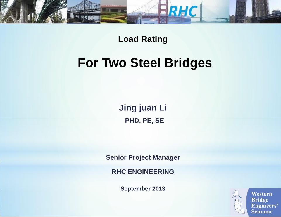
Steel Plate Girder Bridge (LFR)
Jing Juan Li, PHD, PE, SE
RHC ENGINEERING
www.rhcengineering.com
R=300’
Structural Details
Steel Plate Girder
Intermediate crossbeam
Pier Crossbeam
Pier Cap beam
Rating Components
Jing Juan Li, PHD, PE, SE
Steel Plate Girder Bridge (LFR) RHC ENGINEERING
www.rhcengineering.com

(b): Composite section for live load
(c): Model with deck element for analyzing internal cross-frame
(a): Non-composite section for dead load
Global Analysis of Demand
Jing Juan Li, PHD, PE, SE
SAP2000 3D Analysis
Steel Plate Girder Bridge (LFR)
Dead Load:
All existing components weight
Non-composite section
Live load:
Design Live Loads: HS-20
Legal Trucks: 25-40 short tons
Permit Trucks: 103.5 short tons
Composite section
RHC ENGINEERING
www.rhcengineering.com

Determine Member Demand and Capacity
Jing Juan Li, PHD, PE, SE
Component behavior:
Plate girder positive flexure at middle span
• Section is non-compact, use flange stress
• Non-composite section under dead load
• Uncracked composite section for live load
• Bottom flange resistance: steel yielding
Plate girder negative flexural at pier
• Section is non-compact, use flange stress
• Non-composite section for dead load
• Cracked composite section for live load
• Bottom flange compression stress:
flange and web buckling control
Plate girder web shear: web buckling control
Steel Plate Girder Bridge (LFR) RHC ENGINEERING
www.rhcengineering.com
Jing Juan Li, PHD, PE, SE
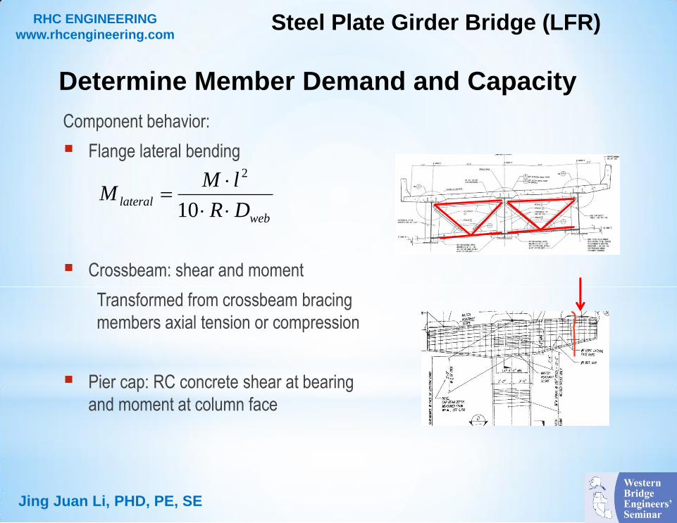
Component behavior:
Flange lateral bending
Crossbeam: shear and moment
Transformed from crossbeam bracing
members axial tension or compression
Pier cap: RC concrete shear at bearing
and moment at column face
Steel Plate Girder Bridge (LFR)
Determine Member Demand and Capacity
web
lateralDR
lMM
10
2
RHC ENGINEERING
www.rhcengineering.com

LFR Rating Equation
Jing Juan Li, PHD, PE, SE
RF: rating factor
Φ: Material resistance factor
Φ=1.0, for steel flexural and shear
Φ=0.9, for concrete flexural
Φ=0.85, for concrete shear
γDL, dead load factor: 1.3
DL: dead load effect on rating
components
S=0 (no prestress effect)
γLL, live load factor: 2.17 or 1.3
LL(1+IM): live load plus impact
Steel Plate Girder Bridge (LFR)
IMLL
SDLCRF
LL
DL
1
Member resistance according to
AASHTO Standard Specifications
for Highway Bridge, 17th edition
RHC ENGINEERING
www.rhcengineering.com

Truck
Inventory Operating
Controlling Point
RF Tons (US) RF Tons (US)
AASHTO 1 1.51 38 2.52 63 CAP BEAM SHEAR AT PIER 3
AASHTO 2 1.12 40 1.87 67 CAP BEAM SHEAR AT PIER 3
AASHTO 3 1.05 42 1.75 70 CAP BEAM SHEAR AT PIER 3
NRL 0.95 38 1.59 64 CAP BEAM SHEAR AT PIER 3
OL-1 0.96 46 1.71 82 CAP BEAM SHEAR AT PIER 3
OL-2 0.50 52 0.89 92 CAP BEAM SHEAR AT PIER 3
Load Rating Results
Jing Juan Li, PHD, PE, SE
NBI Rating RF Tons (US) Controlling Point
Inventory (HS20) 0.99 35 CAP BEAM SHEAR AT PIER 3
Operating (HS20) 1.65 59 CAP BEAM SHEAR AT PIER 3
Steel Plate Girder Bridge (LFR) RHC ENGINEERING
www.rhcengineering.com

LRFR Load Rating of the Steel Box Girder Bridge
Location: JCT S182 &
Keene Road, Richland
Owner: City of
Richland/WSDOT
Year built: 1982
Inspection: Dec. 2008
• Superstructure in
very good condition
(index code: 8)
• Substructure in very
good condition
(index code: 8)
Year widened: 2012
Jing Juan Li, PHD, PE, SE
RHC ENGINEERING
www.rhcengineering.com
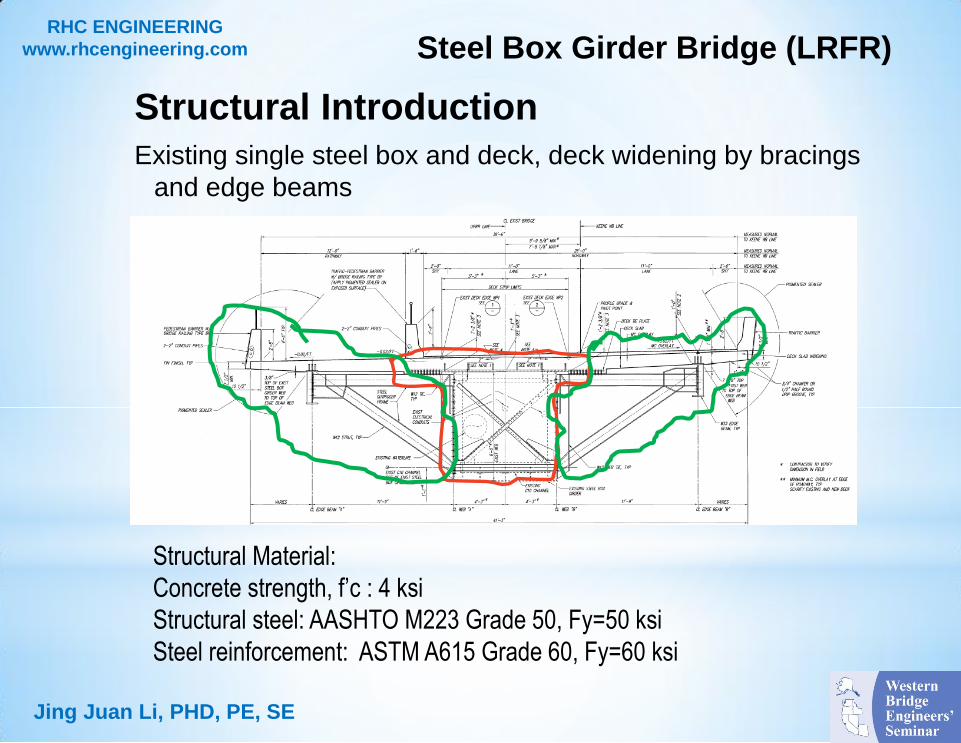
Structural Introduction
Existing single steel box and deck, deck widening by bracings
and edge beams
Steel Box Girder Bridge (LRFR)
Jing Juan Li, PHD, PE, SE
Structural Material:
Concrete strength, f’c : 4 ksi
Structural steel: AASHTO M223 Grade 50, Fy=50 ksi
Steel reinforcement: ASTM A615 Grade 60, Fy=60 ksi
RHC ENGINEERING
www.rhcengineering.com

Steel box girder: top and
bottom flange normal stress,
web shear stress
Splice Connections: flexural
and shear
Crossbeam bracings: tension
or compression
Deck tie: tension
Outrigger bracings: Axial and
flexural
Edge beam: flexural
Rating Components
Jing Juan Li, PHD, PE, SE
Continuous
edge beam Outrigger
bracing Deck tie
Steel Box Girder Bridge (LRFR) RHC ENGINEERING
www.rhcengineering.com

Demand:
SAP2000 Stick Model
Capacity:
Excel and VBA
Component Demand
Pier 1
Pier 2
Pier 3
Pier 4
Jing Juan Li, PHD, PE, SE
Stage 0 Stage 1
Stage 2
Steel Box Girder Bridge (LRFR) RHC ENGINEERING
www.rhcengineering.com
Component resistance
Jing Juan Li, PHD, PE, SE
Component behavior:
Box girder top and bottom flange normal stress, web shear stress
Box girder splices: shear and moment
Outrigger bracing: axial and flexural
Deck tie: axial tension
Edge beam: flexural (non-composite section for dead load, composite
section for live load)
Steel Box Girder Bridge (LRFR) RHC ENGINEERING
www.rhcengineering.com

Iteration on component resistance
Jing Juan Li, PHD, PE, SE
Component behavior:
Box girder top and bottom flange normal stress, shear stress
Outrigger bracing: axial and flexural
Steel Box Girder Bridge (LRFR)
0.10.2
2.0
ry
uy
rx
ux
r
u
r
u
M
M
M
M
P
P
P
PIf
0.19
8
2.0
ry
uy
rx
ux
r
u
r
u
M
M
M
M
P
P
P
PIf
fc
v
yc
vychbnc
tA
Tf
F
fFRRF
02
31
RHC ENGINEERING
www.rhcengineering.com

LRFR Rating Equation
Jing Juan Li, PHD, PE, SE
Strength and service limit state
Φ: resistance factor
Φ=ΦcΦsΦn
γDL: dead load factor
DL: dead load effect on rating
components
S=0 (no prestress effect)
γLL: live load factor
LL(1+IM): live load plus impact
Steel Box Girder Bridge (LRFR)
IMLL
SDLCRF
LL
DL
1
Member resistance according
AASHTO LRFD Bridge Design
Specifications, 5th edition
RHC ENGINEERING
www.rhcengineering.com
Material resistance factors
Jing Juan Li, PHD, PE, SE
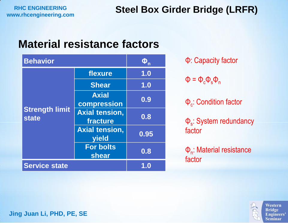
Φ: Capacity factor
Φ = ΦcΦsΦn
Φc: Condition factor
Φs: System redundancy
factor
Φn: Material resistance
factor
Steel Box Girder Bridge (LRFR)
Behavior Φn
Strength limit
state
flexure 1.0
Shear 1.0
Axial
compression 0.9
Axial tension,
fracture 0.8
Axial tension,
yield 0.95
For bolts
shear 0.8
Service state 1.0
RHC ENGINEERING
www.rhcengineering.com

Load and Factors
Jing Juan Li, PHD, PE, SE
Dead Load: All existing components weight
Live load:
Design Live Loads: HL-93
Legal Trucks: 25-40 short tons
Permit Trucks: 103.5 short tons
Load Factors
Steel Box Girder Bridge (LRFR)
Limit State ᵞDC ᵞDW
HL-93
Inventory
HL-93
Operating
Legal and
NRL Permit
Strength 1.25 1.5 1.75 1.35 1.8 1.5
Service 1.0 1.0 1.30 1.0 1.30 1.0
RHC ENGINEERING
www.rhcengineering.com
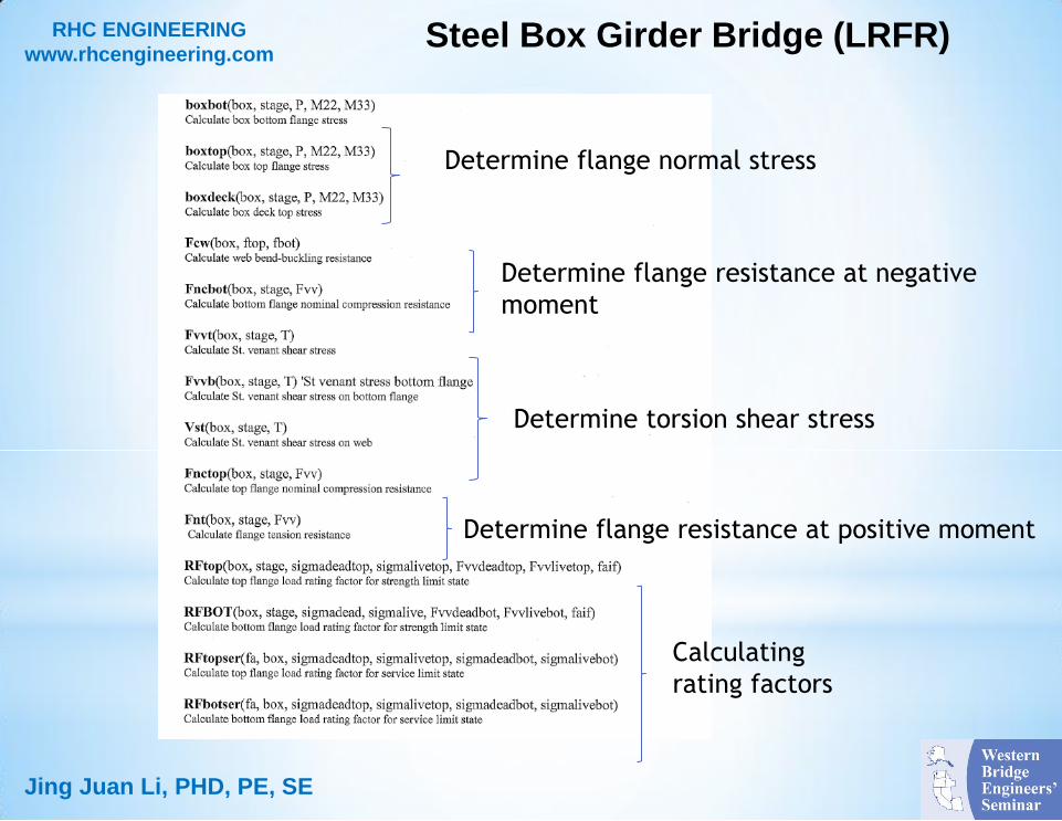
Jing Juan Li, PHD, PE, SE
Determine flange normal stress
Determine torsion shear stress
Determine flange resistance at positive moment
Calculating
rating factors
Determine flange resistance at negative
moment
Steel Box Girder Bridge (LRFR) RHC ENGINEERING
www.rhcengineering.com
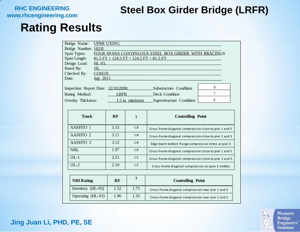
Rating Results
Jing Juan Li, PHD, PE, SE
Bridge Name: UPRR UXING
Bridge Number: 182/8 Span Types: FOUR SPANS CONTINUOUS STEEL BOX GIRDER WITH BRACINGS Span Length: 81.5 FT + 124.5 FT + 124.5 FT + 81.5 FT
Design Load: HL-93. Rated By: JJL
Checked By: COH/JX Date: July 2011
Inspection Report Date: 12/10/2008
Rating Method: LRFR
Overlay Thickness: 1.5 in. minimum
Substructure Condition
Deck Condition
Superstructure Condition
Truck RF γ Controlling Point
AASHTO 1 3.15 1.8 Cross-frame diagonal compression close to pier 1 and 5
AASHTO 2 3.11 1.8 Cross-frame diagonal compression close to pier 1 and 5
AASHTO 3 3.12 1.8 Edge beam bottom flange compressive stress at pier 3
NRL 1.97 1.8 Cross-frame diagonal compression close to pier 1 and 5
OL-1 2.51 1.5 Cross-frame diagonal compression close to pier 1 and 5
OL-2 2.10 1.5 Cross-frame diagonal compression at span 2 middle
NBI Rating RF γ
Controlling Point
Inventory (HL-93) 1.52 1.75 Cross-frame diagonal compression near pier 1 and 5
Operating (HL-93) 1.96 1.35 Cross-frame diagonal compression near pier 1 and 5
Remarks:
8
7
8
Steel Box Girder Bridge (LRFR) RHC ENGINEERING
www.rhcengineering.com

SUMMARY
3D line models with moderate complexity to analyze member demand
Construction staging
Member resistance using Excel
Steel plate girder bridge (LFR):
Pier cap beam shear controls rating factor
Steel box girder bridge (LRFR)
Crossbeam diagonal compression controls rating factor
Development of generalized rating tools combining commercial software and
Excel spreadsheets.
Jing Juan Li, PHD, PE, SE

QUESTIONS?
Thank you for your attention !
Jing Juan Li, PHD, PE, SE