BOX - Home | Halton · 3 BOX - Airflow management unit FUNCTION 20/BOX/1015/EN The Halton BOX...
16
1 BOX - Airflow management unit 20/BOX/1015/EN BOX Airflow management unit Solution • Airflow management and control unit • Variable or constant airflow rate operation • Pressure-independent operation • Galvanised steel construction • Airflow management plenum with acoustic attenuation (high density mineral wool) • Factory set airflow range limit Options & Accessories • Electrical reheating unit WBF or water reheating unit WBO • Outlet plenum PBO with one or more circular connections • External insulation for radiated noise attenuation MATERIAL PART MATERIAL Plenum Galvanised steel Measurement probe Aluminium Acoustic insulation High density mineral wool Blade Galvanised steel Perforated sheet steel Galvanised steel External insulation Mineral wool protected by galvanised steel frame
Transcript of BOX - Home | Halton · 3 BOX - Airflow management unit FUNCTION 20/BOX/1015/EN The Halton BOX...

111
BOX - Airflow management unit
20
/BO
X/1
015
/EN
BOXAirflow management unit
Solution
• Airflow management and control unit
• Variable or constant airflow rate operation
• Pressure-independent operation
• Galvanised steel construction
• Airflow management plenum with acoustic
attenuation (high density mineral wool)
• Factory set airflow range limit
Options & Accessories
• Electrical reheating unit WBF or water reheating unit
WBO
• Outlet plenum PBO with one or more circular
connections
• External insulation for radiated noise attenuation
MATERIAL
PART MATERIAL
Plenum Galvanised steel
Measurement probe Aluminium
Acoustic insulation High density mineral wool
Blade Galvanised steel
Perforated sheet steel Galvanised steel
External insulation Mineral wool protected by galvanised steel frame

2
20
/BO
X/1
015
/EN
BOX - Airflow management unit
DIMENSIONS
Short version: BOX/S. Long version: BOX/L
BOX/S BOX/L
Diameter D [mm]
Width X [mm]
Height Y [mm]
Length L[mm]
Length L [mm]
25 mm Insulation,
I1
100 400 250 600 1000125 400 250 600 1000160 400 250 600 1000200 600 280 600 1200250 700 320 900 1400315 800 400 900 1600355 1000 450 900 1600*400 1000 450 900 1600*500 1300 550 900 1800*
40 mm Insulation,
I2
100 430 280 600 1000125 430 280 600 1000160 430 280 600 1000200 630 310 600 1200250 730 350 900 1400315 830 430 900 1600355 1030 480 900 1600*400 1030 480 900 1600*500 1330 580 900 1800*
* in 2 parts.Nb : The actuator is installed on the right side of the BOX (like drawing above); it can be installed on the left side on demand.
L
170
X
Y
70
air direction
L
170
X
Y
70air direction
Supply BOX
Exhaust BOX

3
BOX - Airflow management unit
20
/BO
X/1
015
/EN
FUNCTION
The Halton BOX variable airflow rate management unit contains a complete regulation loop. This includes an
aluminium probe measurement system to take the average value measured over the whole crossing surface, an
actuator mounted on the blade axis and a controller.
The measurements made are sent to the controller which compares these values with the required setpoint value;
depending on the measured difference, a signal is then sent to the actuator so that the unit compensates for this
difference.
An analog signal that enables the setpoint to be shifted may also be sent to the controller. The flow rate is
regulated between the min and max rate values programmed into the controller.
The regulation loop is closed and operates independently of the variations in upstream pressure. The regulation may
also be static pressure regulation (in the duct or in the premises).
FC
M
TC
FE
BOX
M: actuator
PE: dynamic pressure measurement probe
FC: airflow controller
TC: thermostat or room sensor

4
20
/BO
X/1
015
/EN
BOX - Airflow management unit
WATER REHEATING UNIT WBO OPTION
• Rectangular water reheating to be mounted
downstream of the airflow management unit BOX.
• Lateral water connection.
• Fixing on the BOX by toggle latches.
• Cooling coil with condensate tray can be
manufactured upon request.
ELECTRICAL REHEATING WBF OPTION
• Electrical reheating with electrical supply 230 V single
phase (1 or 2 resistances), 230/400 V three phase (3
resistances).
• Safety thermostat with manual reset.
• Minimum air velocity: 2 m/s.
WBO - WBF dimensions
D X Y L
25 mmInsulation,
I1
100 400 250 300
125 400 250 300
160 400 250 300
200 600 280 300
250 700 320 300
315 800 400 500
355 1000 450 600
400 1000 450 600
500 1300 550 600
40 mmInsulation,
I2
100 430 280 300
125 430 280 300
160 430 280 300
200 630 310 300
250 730 350 300
315 830 430 500
355 1030 480 600
400 1030 480 600
500 1330 580 600
L X
Y
Water reheating power
SizeAirflow(m³/h)
Airflow(l/s)
Power∆P(Pa)
100
58 16 425 297 27 641 3
136 38 824 5175 49 986 7214 59 1129 10251 70 1255 13
125
90 25 603 3155 43 904 6220 61 1149 10285 79 1363 15350 97 1555 21414 115 1727 28
160
144 40 859 6254 71 1266 13364 101 1593 23474 132 1877 35584 162 2115 49695 193 2326 65
200
227 63 1440 4427 119 2238 10627 174 2882 18827 230 3424 28
1027 285 3889 401226 341 4315 54
250
360 100 2320 4675 188 3611 11990 275 4644 19
1305 363 5515 301620 450 6288 431936 538 6953 58
315
569 158 3530 51039 289 5378 121509 419 6849 221979 550 8086 342449 680 9145 492920 811 10120 65
355
736 204 4577 41395 388 7205 102054 571 9286 192713 754 11036 293372 937 12535 424032 1120 13856 56
400
900 250 5330 51600 444 7899 132300 639 9964 223000 833 11702 343700 1028 13188 494400 1222 14557 65
500
1404 390 8749 52643 734 13611 123882 1078 17480 225121 1423 20724 346360 1767 23493 487600 2111 25923 65
X
60
Y
L

5
BOX - Airflow management unit
20
/BO
X/1
015
/EN
MODELS
The BOX airflow management unit is available in several versions.
The long version is used to reduce the airflow noise; the version with exterior sound proofing is used to reduce the
radiated noise emitted by the unit.
MODEL APPLICATION EXECUTION
BOX/S-S, IN=I1 Supply. Short version. 25 mm insulation.
BOX/L-S, IN=I1 Supply. Low noise level to be complied. Long version. Integrated sound attenuator. 25 mm insulation.
BOX/S-E, IN=I1 Exhaust. Short version. 25 mm insulation.
BOX/L-E, IN=I1 Exhaust. Low noise level to be complied. Long version. 25 mm insulation.
BOX/S-S, IN=I2 Supply. Short version. 40 mm insulation.
BOX/L-S, IN=I2 Supply. Low noise level to be complied. Long version. Integrated sound attenuator. 40 mm insulation.
BOX /S /E, IN=I2 Exhaust. Short version. 40 mm insulation.
BOX/L-E, IN=I2 Low noise level to be complied. Long version. 40 mm insulation.
PBO dimensions
D X Y D2 L
25 mmInsulation,
I1
100 400 250 125 200
125 400 250 160 200
160 400 250 200 200
200 600 280 250 200
315 800 400 355 200
355 1000 450 400 200
40 mmInsulation,
I2
100 430 280 125 200
125 430 280 160 200
160 430 280 200 200
200 630 310 250 200
315 830 430 355 200
355 1030 480 400 200
Upon request, outlet plenum PBO: - with side connection, - with several connections.
PLENUM PBO OPTION
Plenum with 1 circular outlet to be mounted downstream
of the airflow management unit BOX.
6
20
/BO
X/1
015
/EN
BOX - Airflow management unit
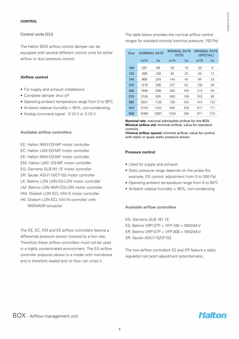
CONTROL
Control units (CU)
The Halton BOX airflow control damper can be
equipped with several different control units for either
airflow or duct pressure control.
Airflow control
• For supply and exhaust installations
• Complete damper shut off
• Operating ambient temperature range from 0 to 50ºC
• Ambient relative humidity < 95%, non-condensing
• Analog command signal: 0-10 V or 2-10 V.
Available airflow controllers
EE: Halton NMV-D3-MP motor controller
EC: Halton LMV-D3-MP motor controller
EK: Halton NMV-D3-MF motor controller
EM: Halton LMV -D3-MF motor controller
EG: Siemens GLB181.1E motor controller
SR: Sauter ASV/115/CF152 motor controller
LK: Belimo LON LMV-D3-LON motor controller
LM: Belimo LON NMV-D3-LON motor controller
HM: Distech LON ECL-VAV-S motor controller
HK: Distech LON ECL-VAV-N controller with
NM24ASR actuactor
The EE, EC, EM and EK airflow controllers feature a
differential pressure sensor crossed by a low rate.
Therefore these airflow controllers must not be used
in a highly contaminated environment. The EG airflow
controller pressure sensor is a model with membrane
and is therefore sealed and no flow can cross it.
The table below provides the nominal airflow control
ranges for standard controls (nominal pressure: 150 Pa):
Size NOMINAL RATE MINIMAL RATE
(STD)MINIMAL RATE
(SPECIAL)
m3/h l/s m3/h l/s m3/h l/s
100 287 80 58 16 28 8
125 469 130 90 25 46 13
160 808 224 144 40 84 23
200 1210 336 227 63 136 38
250 1940 539 360 100 214 59
315 3145 874 569 158 353 98
355 4031 1120 736 204 444 123
400 5159 1433 900 250 617 171
500 8160 2267 1404 390 971 270
Nominal rate: maximal admissible airflow for the BOX.Minimal airflow std: minimal airflow, value for standard controls.Minimal airflow special: minimal airflow, value for control with static or quasi-static pressure sensor.
Pressure control
• Used for supply and exhaust
• Static pressure range depends on the probe (for
example, EG control: adjustment from 0 to 300 Pa)
• Operating ambient temperature range from 0 to 50°C
• Ambient relative humidity < 95%, non-condensing
Available airflow controllers
EG: Siemens GLB.181.1E
ES: Belimo VRP-STP + VFP-100 + NM24A-V
ER: Belimo VRP-STP + VFP-300 + NM24A-V
SR: Sauter ASV/115/CF152
The two airflow controllers ES and ER feature a static
regulation set point adjustment potentiometer.

7
BOX - Airflow management unit
20
/BO
X/1
015
/EN
INSTALLATION
Safety distance
The Halton BOX airflow control damper is installed taking into account the required safety distances (see figure).
These distances are valid for supply and exhaust. If the safety distances below are not respected, the dynamic
pressure measurement can be false.
For the supply, in static pressure control, the minimum safety distance for the static measurement unit after the
control damper is 5 x D in supply air applications. However, the pressure sensor position is typically halfway along
or in the last third of in the last third of the duct branch length.
BOXHFBHFDHFLMSA
BOXHFBHFDHFLMSA

8
20
/BO
X/1
015
/EN
BOX - Airflow management unit
WIRING
The wiring shall be carried out in accordance with local regulations and by professional technicians.
Belimo control - Airflow controlBOX; CU = EE, EC, EM or EK – Wiring and imperative command
The Halton service boundary is represented by dashes.
Belimo control - Supply/exhaust parallel control - Airflow controlBOX; CU = EE, EC, EK or EM
The Halton service boundary is represented by dashes.
CODE DESCRIPTION
1 (^) 24 VAC system neutral
2 (~) 24 VAC phase
3 (w) 2-10 or 0-10 VDC airflow setpoint signal input
5 (U5) 2-10 or 0-10 VDC airflow feedback signal output
*) Diode
CODE DESCRIPTION
1 (^) 24 VAC system neutral
2 (~) 24 VAC phase
3 (w) 2-10 or 0-10 VDC airflow setpoint signal input
5 (U5) 2-10 or 0-10 VDC airflow feedback signal output
PLC Building Management System
C (AO) Airflow setpoint control signal
F (AI) Actual airflow feedback input
Mode - 0...10 V 0...10 V 0...10 V 0...10 V
2...10 V 2...10 V 2...10 V 2...10 V 2...10 V
Signal
Function
⊥-
3
0...10 V
2...10 V
3
~
3
~+
3
~
3Closed a)CLOSED c)CLOSED
Min...Max airflow b)VAV
CAV - Min airflow Fully open - Min active airflow**
Full opening e)OPEN*
CAV - Max airflowd) Max airflow
Operating mode
There are two possible operating modes: 0 to 10 VDC and
2 to 10 VDC. The main differences between these modes
are related to low airflow control and closing function.
Closing and imperative command
Except the case where a relay cut off the control, the damper will
be fully closed if:
• 0-10 VDC mode: The BOX minimal airflow is set to 0 and the w
control signal falls below 0,5V
• 2-10 VDC mode : the w control signal falls below 0,1V.
Closed contact, active function
Closed contact, active function, in 2...10 VDC only
Open contact
* Not available in 24 VDC power supply** The controller closes when 0.5 V power cut mode is used.

9
BOX - Airflow management unit
20
/BO
X/1
015
/EN
Siemens ControlBOX; CU=EG (GLB181.1E/3)
The Halton service boundary is represented by dashes.
BOX; CU=ES or CU=ER - Duct pressure control
The Halton service boundary is represented by dashes.
Override A B
Closed ON OFF
Pressure control OFF OFF
Open ON ON
The pressure controller has a setpoint potentiometer for pressure setpoint adjustment.
CODE DESCRIPTION
2 (G0) 24 VAC system neutral
1 (G) 24 VAC phase
8 (YC) 0-10 VDC airflow setpoint signal input
9 (U) 0-10 VDC airflow feedback signal output
6 (Y1) Override input
7 (Y2) Override input
CODE DESCRIPTION
1 (^) 24 VAC system neutral
2 (~) 24 VAC phase
3 (w1) 2-10 VDC duct pressure setpoint signal input (if used)
5 (U5) 2-10 VDC duct pressure feedback signal output
6 (y) Actuator signal
7 (z) Override input
*) Diode
**) factory-fitted 2-4 jumper for the potentiometer setpoint; remove if w1 2-10 VDC input is used
***) Minimum safety distance for pressure tab after pressure control damper (5 x D)
Constant flow A B
Closed ON OFF
Min. flow OFF OFF
Max. flow ON ON
Full opening ON OFF

10
20
/BO
X/1
015
/EN
BOX - Airflow management unit
COMMISSIONING
The actual airflow rate can be calculated as a function of differential pressure at the measurement probe and the
measurement probe k factor. The proper k factor can be found in the documentation supplied with the product.
Qv = k x √ ∆P_m
Qv : actual airflow rate [l/s]k : k factor of the product∆P_m : diffrential pressure of the measurement probe [Pa]
The EE, EC, EK and EM airflow controllers are equipped with a dynamic pressure differential sensor which is
subjected to a low airflow. Therefore, a manual manometer cannot be connected in parallel with the airflow
controller for differential pressure measurement. If a manual manometer is used, the airflow controller power
supply shall be switched off in order to stop damper movement during measurement of the airflow probe
differential pressure. Note that the duct pressure might vary during the measurement.
The EG airflow controller is equipped with a static membrane pressure sensor including an automatic zero point
calibration, and there is no airflow through the differential pressure sensor of the controller. Therefore, a manual
differential measurement manometer can be connected in parallel to the airflow controller (for example, with tube
T-branches), and both measurements can operate in parallel with continuous control.
Duct pressure control
The actual measured airflow rate (qv) can be defined by the controller feedback signal (U5) and airflow controller
nominal airflow (qv_nom).
The actual static duct pressure can also be read from the pictures below:
SIGNAL FORMULA CONTROLLER TYPE & MODENEUTRAL SYSTEM TERMINALS
SIGNALTERMINALS
2 to 10 VDCPst = 100Pa*(U-2)/8 BOX;CU=ES (VRP-STP+VFP-100) 1 (^) 5(U5)
Pst = 300Pa*(U-2)/8 BOX;CU=ER(VRP- STP+VFP-300) 1 (^) 5(U5)

11
BOX - Airflow management unit
20
/BO
X/1
015
/EN
SOUND DATA
BOX/L-S
Airborne noise Upstream pressure 100 Pa
D
mm
Qv
m³/h
Qv
l/s
F (Hz) LwA
dBA
LpA
dBA
NR
dB125 250 500 1000 2000 4000 8000
100 47 13 31 26 16 13 14 18 21 24 16 20158 44 42 36 25 14 15 20 22 26 18 21212 59 43 38 29 15 16 20 21 26 18 20287 79 43 38 29 15 16 20 21 26 18 20
125 79 22 32 31 19 14 15 20 23 26 18 22266 74 45 41 26 18 16 20 23 28 20 22349 97 46 44 31 20 17 21 22 30 22 21469 130 46 44 31 20 17 21 22 30 22 21
160 137 38 35 32 21 15 14 19 23 25 18 22457 127 44 41 30 21 18 20 23 30 22 22601 167 50 44 34 26 25 23 23 33 25 22808 224 50 44 34 26 25 23 23 33 25 22
200 220 61 37 31 21 16 15 19 23 26 18 22734 204 44 38 29 25 23 20 22 31 23 21972 270 48 42 35 32 30 26 24 37 29 25
1210 336 48 42 35 32 30 26 24 37 29 25
250 353 98 40 31 19 21 14 17 21 26 18 201181 328 48 42 28 21 18 21 22 32 24 211559 433 52 46 33 25 23 23 23 36 28 221940 539 52 46 33 25 23 23 23 36 28 25
315 576 160 43 36 28 21 25 23 29 33 25 281915 532 54 47 37 30 30 29 31 40 32 302531 703 57 50 41 34 34 33 33 43 35 323146 874 57 50 41 34 34 33 33 43 35 32
355 736 204 43 38 29 23 26 25 30 34 26 292452 681 55 53 41 35 34 32 32 44 36 313244 901 59 53 41 35 34 32 32 44 36 314032 1120 59 53 41 35 34 32 32 44 36 31
400 943 262 45 39 31 27 26 25 29 35 27 283139 872 54 50 41 37 34 33 32 44 36 314147 1152 58 52 45 41 39 37 35 48 40 345159 1433 61 57 50 44 44 42 37 52 45 40
BOX/L-S
Airborne noiseUpstream pressure 500 Pa
D
mm
Qv
m³/h
Qv
l/s
F (Hz) LwA
dBA
LpA
dBA
NR
dB125 250 500 1000 2000 4000 8000
100 47 13 35 33 27 17 15 20 24 27 19 23158 44 50 46 40 23 21 23 26 33 25 25212 59 56 52 44 23 22 24 25 37 29 25287 79 60 54 45 24 23 26 26 38 30 26
125 79 22 37 36 34 23 17 22 26 31 23 25266 74 53 50 41 26 22 25 28 36 28 27349 97 57 55 42 27 24 26 28 39 31 27469 130 61 58 45 30 27 28 28 42 34 29
160 137 38 44 41 39 27 25 24 26 35 27 25457 127 58 54 43 28 26 31 32 41 33 31601 167 62 56 46 32 30 33 32 44 36 31808 224 65 60 48 35 34 34 33 47 39 34
200 220 61 48 41 38 26 20 23 27 35 27 26734 204 61 55 43 32 29 28 30 43 35 30972 270 64 58 45 36 34 31 31 45 38 34
1210 336 64 59 46 40 39 36 33 48 40 35
250 353 98 55 47 36 33 29 28 31 39 31 301181 328 67 57 46 34 30 33 35 47 39 341559 433 70 60 47 35 33 38 40 50 42 391940 539 69 63 49 37 34 40 38 52 44 41
315 576 160 52 60 53 37 38 40 39 52 44 411915 532 65 60 52 43 43 43 41 53 45 402531 703 68 63 54 45 45 44 46 55 48 453146 874 68 63 54 45 45 44 46 55 48 45
355 736 204 51 59 52 38 39 43 41 52 44 402452 681 66 63 54 45 45 46 44 55 48 433244 901 70 66 58 48 48 47 45 59 51 464032 1120 70 66 58 48 48 47 45 59 51 46
400 943 262 53 58 53 40 45 45 42 54 46 423139 872 68 63 56 52 52 49 48 59 51 474147 1152 67 63 55 52 51 48 46 59 51 465159 1433 67 63 55 52 51 48 46 59 51 46
BOX/L-S
Airborne noise Upstream pressure 200 Pa
D
mm
Qv
m³/h
Qv
l/s
F (Hz) LwA
dBA
LpA
dBA
NR
dB125 250 500 1000 2000 4000 8000
100 47 13 33 30 21 14 14 19 23 25 17 22158 44 46 44 32 16 16 20 23 28 20 22212 59 50 46 34 19 19 21 24 30 22 23287 79 51 46 36 19 19 22 24 31 23 23
125 79 22 35 35 26 17 16 21 23 27 19 22266 74 49 45 34 19 18 21 23 31 23 22349 97 52 49 37 22 19 22 23 34 26 22469 130 56 52 39 26 23 24 25 36 28 24
160 137 38 37 38 26 16 17 21 23 28 20 22457 127 51 46 34 23 21 23 24 33 25 23601 167 57 49 39 29 28 26 25 38 30 24808 224 58 51 40 32 31 29 27 40 32 26
200 220 61 40 36 28 17 15 20 23 28 20 22734 204 51 46 33 27 25 22 23 35 27 22972 270 52 48 37 33 32 27 25 39 31 27
1210 336 56 51 41 38 37 33 30 44 36 32
250 353 98 48 40 28 18 24 21 23 32 24 221181 328 58 50 37 27 23 24 24 39 31 271559 433 60 53 41 33 29 27 26 43 35 301940 539 58 54 40 31 30 29 28 43 35 31
315 576 160 50 49 38 27 30 33 30 41 33 301915 532 58 53 43 35 35 34 33 45 37 322531 703 62 57 46 37 38 38 36 49 41 363146 874 65 58 49 41 40 40 38 51 43 37
355 736 204 47 48 38 27 32 36 32 42 34 332452 681 60 55 46 39 38 37 37 48 40 363244 901 64 59 50 44 42 41 40 52 44 394032 1120 66 61 53 46 45 44 42 55 47 41
400 943 262 49 48 39 31 33 34 31 42 34 313139 872 59 55 47 44 42 39 36 51 42 374147 1152 62 59 50 45 44 44 40 53 45 415159 1433 62 59 50 45 44 44 40 53 45 41

12
20
/BO
X/1
015
/EN
BOX - Airflow management unit
SOUND DATA
BOX/L-E
Airborne noiseUpstream pressure 100 Pa
D
mm
Qv
m³/h
Qv
l/s
F (Hz) LwA
dBA
LpA
dBA
NR
dB125 250 500 1000 2000 4000 8000
100 47 13 31 27 22 13 15 21 31 31 23 30158 44 43 38 33 20 17 22 31 32 24 30212 59 43 42 37 20 18 22 30 32 24 29287 79 43 42 37 20 18 22 30 32 24 29
125 79 22 31 29 24 14 15 22 31 31 23 30266 74 42 40 35 17 16 22 31 33 25 30349 97 41 43 37 21 18 23 31 34 26 30469 130 41 43 37 21 18 23 31 34 26 30
160 137 38 37 35 29 20 18 22 31 32 24 30457 127 44 42 37 22 18 23 31 34 26 30601 167 45 45 38 22 18 23 31 35 27 30808 224 45 45 38 22 18 23 31 35 27 30
200 220 61 38 39 29 18 16 21 30 32 24 29734 204 44 45 37 120 18 22 30 35 27 29972 270 47 49 41 26 22 25 30 39 31 29
1210 336 49 53 45 31 26 27 30 42 34 31
250 353 98 37 38 26 18 17 21 30 32 24 291181 328 45 47 35 20 17 21 30 35 28 291559 433 48 52 638 26 20 22 30 40 32 291940 539 48 52 38 26 20 22 30 40 32 29
315 576 160 40 37 26 18 18 22 31 33 25 301915 532 49 49 38 23 21 23 31 39 31 302531 703 51 53 41 29 25 25 31 43 35 313146 874 51 53 41 29 25 25 31 43 35 31
355 736 204 40 36 26 20 19 22 30 32 24 292452 681 46 48 40 27 23 23 31 40 32 303244 901 49 51 46 36 31 26 31 45 37 344032 1120 49 51 46 36 31 26 31 45 37 34
400 943 262 40 38 28 20 18 22 30 33 25 293139 872 46 49 39 28 24 23 30 41 33 294147 1152 49 52 46 36 31 26 30 45 38 345159 1433 49 52 46 36 31 26 30 45 38 34
BOX/L-E
Airborne noiseUpstream pressure 500 Pa
D
mm
Qv
m³/h
Qv
l/s
F (Hz) LwA
dBA
LpA
dBA
NR
dB125 250 500 1000 2000 4000 8000
100 47 13 39 35 22 14 16 24 33 33 25 32158 44 43 45 41 26 22 26 31 35 27 30212 59 50 51 45 31 24 28 31 38 30 30287 79 52 53 48 33 27 31 32 41 33 31
125 79 22 33 34 27 16 16 22 31 31 23 30266 74 50 49 43 30 22 27 31 38 30 30349 97 53 53 46 34 25 29 32 41 33 31469 130 55 57 51 37 28 31 32 45 37 34
160 137 38 37 39 33 23 23 25 32 34 26 31457 127 52 51 47 37 28 31 34 43 35 33601 167 56 55 51 42 29 33 35 47 39 36808 224 59 58 54 45 30 34 36 50 42 39
200 220 61 39 46 36 28 25 26 30 37 29 29734 204 58 58 51 32 27 29 30 48 40 37972 270 60 61 53 38 32 34 34 50 42 39
1210 336 62 63 55 43 35 38 37 52 44 41
250 353 98 39 44 34 26 24 25 30 36 28 291181 328 58 58 46 33 26 29 31 45 38 351559 433 61 61 51 36 28 31 32 50 42 381940 539 61 61 51 36 28 31 32 50 42 38
315 576 160 45 45 35 26 25 29 32 38 30 311915 532 63 60 49 37 35 35 33 50 42 392531 703 66 63 53 40 38 37 34 54 46 423146 874 67 66 57 43 39 39 35 57 49 46
355 736 204 47 43 37 31 33 33 30 40 32 302452 681 60 59 50 41 41 39 37 52 44 393244 901 63 63 54 44 43 41 38 55 47 434032 1120 65 66 58 47 45 42 38 58 50 46
400 943 262 47 43 41 31 31 31 32 51 33 313139 872 61 59 52 43 43 41 36 53 45 404147 1152 63 62 55 45 43 40 36 55 47 435159 1433 63 62 55 45 43 40 36 55 47 43
BOX/L-E
Airborne noiseUpstream pressure 200 Pa
D
mm
Qv
m³/h
Qv
l/s
F (Hz) LwA
dBA
LpA
dBA
NR
dB125 250 500 1000 2000 4000 8000
100 47 13 30 30 23 13 16 22 31 31 23 30158 44 45 42 38 21 18 23 31 33 25 30212 59 46 46 41 23 20 24 31 35 27 30287 79 48 48 43 26 22 25 31 36 28 30
125 79 22 34 32 25 14 16 22 31 31 23 30266 74 47 44 40 24 18 23 31 35 27 30349 97 46 48 43 25 20 24 31 37 29 30469 130 47 51 45 28 22 26 31 39 31 30
160 137 38 37 37 31 30 19 23 31 32 24 30457 127 53 47 46 30 20 25 32 41 33 31601 167 52 51 46 30 21 25 32 41 33 31808 224 51 52 46 31 22 26 32 42 34 31
200 220 61 38 43 34 21 18 22 30 34 26 29734 204 51 51 44 27 23 26 30 41 33 29972 270 52 54 46 30 25 28 31 43 35 32
1210 336 52 56 48 32 27 29 31 45 37 34
250 353 98 40 42 30 18 18 22 30 33 25 291181 328 51 51 42 24 19 23 31 41 33 301559 433 52 54 44 28 22 24 30 43 35 311940 539 52 54 44 28 22 24 30 43 35 31
315 576 160 42 40 29 20 20 24 30 34 26 291915 532 55 55 46 28 27 28 31 46 38 342531 703 58 58 49 31 28 29 31 49 41 373146 874 57 59 50 37 32 31 32 50 42 38
355 736 204 43 39 30 24 26 24 30 35 27 292452 681 54 54 46 33 32 29 31 45 38 343244 901 54 56 49 36 33 29 31 48 40 374032 1120 56 58 54 44 38 33 32 33 45 42
400 943 262 44 40 33 24 23 23 31 36 28 303139 872 54 54 45 34 31 28 30 46 38 344147 1152 55 56 50 37 36 30 31 50 42 385159 1433 55 56 50 37 36 30 31 50 42 38
13
BOX - Airflow management unit
20
/BO
X/1
015
/EN
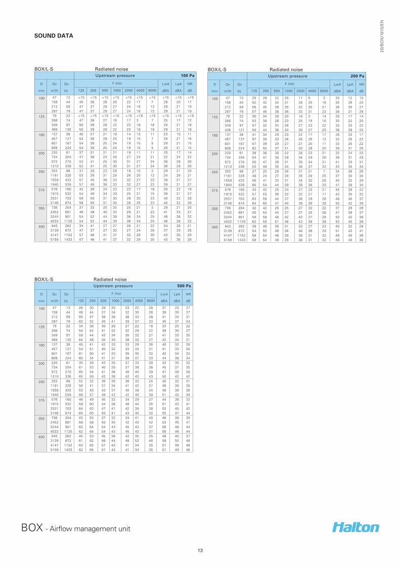
SOUND DATA
BOX/L-S
Radiated noise Upstream pressure 100 Pa
D
mm
Qv
m³/h
Qv
l/s
F (Hz) LwA
dBA
LpA
dBA
NR
dB125 250 500 1000 2000 4000 8000
100 47 13 <15 <15 <15 <15 <15 <15 <15 <15 <15 <15158 44 45 36 28 26 22 17 7 28 20 17212 59 47 37 29 27 24 18 13 29 21 19287 79 47 37 29 27 24 18 13 29 21 19
125 79 22 <15 <15 <15 <15 <15 <15 <15 <15 <15 <15266 74 47 38 27 18 17 3 7 25 17 12349 97 50 39 28 22 23 18 18 29 21 18469 130 50 39 28 22 23 18 18 29 21 18
160 137 38 40 27 21 19 14 13 11 23 15 11457 127 53 36 28 25 19 15 7 29 21 16601 167 54 39 25 24 19 15 5 29 21 15808 224 54 39 25 24 19 15 5 29 21 15
200 220 61 37 31 21 21 19 11 11 25 17 14734 204 47 36 23 26 27 24 21 32 24 22972 270 52 41 25 30 31 27 24 36 28 26
1210 336 52 41 25 30 31 27 24 36 28 26
250 353 98 37 29 22 28 18 10 3 29 21 201181 328 53 39 31 29 26 20 12 34 26 211559 433 57 45 36 33 32 27 23 39 31 271940 539 57 45 36 33 32 27 23 39 31 27
315 576 160 42 36 24 23 23 17 18 30 22 181915 532 54 49 34 29 25 21 15 39 31 272531 703 56 50 31 30 28 25 23 40 32 283146 874 56 50 31 30 28 25 23 40 32 28
355 736 204 37 33 20 20 25 21 3 29 21 202452 681 46 48 40 33 29 21 23 41 33 273244 901 54 52 44 39 36 34 25 46 38 324032 1120 54 52 44 39 36 34 25 46 38 32
400 943 262 34 41 27 27 26 21 22 34 26 213139 872 47 37 37 30 27 24 26 37 29 254147 1152 57 46 41 37 32 29 30 43 35 295159 1433 57 46 41 37 32 29 30 43 35 29
BOX/L-S
Radiated noise Upstream pressure 500 Pa
D
mm
Qv
m³/h
Qv
l/s
F (Hz) LwA
dBA
LpA
dBA
NR
dB125 250 500 1000 2000 4000 8000
100 47 13 26 30 29 25 23 22 28 31 23 27158 44 49 44 37 34 32 30 26 38 30 27212 59 55 47 38 38 36 33 28 41 33 31287 79 62 52 45 41 39 37 33 45 37 34
125 79 22 34 36 36 28 27 22 18 33 25 22266 74 54 42 41 32 32 29 22 38 30 27349 97 59 44 43 34 35 32 27 41 33 30469 130 64 48 45 35 36 33 27 42 34 31
160 137 38 45 41 42 33 33 28 26 40 32 28457 127 54 51 40 32 33 33 31 41 33 30601 167 61 50 41 33 35 35 32 42 34 32808 224 65 34 41 37 38 37 33 44 36 34
200 220 61 35 39 43 35 37 33 28 43 35 32734 204 61 53 40 35 37 38 36 45 37 35972 270 65 54 41 36 40 40 39 47 39 38
1210 336 65 59 43 38 42 43 43 50 42 42
250 353 98 52 32 36 35 36 32 24 40 32 311181 328 56 41 37 34 41 42 37 46 38 391559 433 53 45 43 37 40 39 24 46 38 361940 539 68 57 49 42 42 40 39 51 43 38
315 576 160 46 49 45 32 34 29 27 44 36 321915 532 59 60 44 38 40 44 35 51 43 412531 703 64 63 47 41 42 39 38 53 45 423146 874 65 65 50 41 43 40 32 55 47 44
355 736 204 43 53 37 32 34 41 40 46 38 392452 681 58 58 50 45 42 43 42 53 45 413244 901 62 64 54 43 45 43 37 56 48 444032 1120 62 64 54 43 45 43 37 56 48 44
400 943 262 45 53 45 36 42 35 25 48 40 373139 872 61 62 56 44 48 52 46 58 50 494147 1152 62 65 57 42 41 34 35 57 49 465159 1433 62 65 57 42 41 34 35 57 49 46
BOX/L-S
Radiated noiseUpstream pressure 200 Pa
D
mm
Qv
m³/h
Qv
l/s
F (Hz) LwA
dBA
LpA
dBA
NR
dB125 250 500 1000 2000 4000 8000
100 47 13 20 29 22 20 11 5 3 20 12 10158 44 52 42 34 31 28 25 18 34 26 23212 59 56 45 38 35 32 30 21 38 30 27287 79 57 46 38 36 33 31 23 39 31 28
125 79 22 30 34 29 20 18 3 14 25 17 14266 74 53 38 28 23 25 19 10 30 22 20349 97 57 32 34 26 27 23 22 33 25 22436 121 59 44 38 30 30 27 20 36 28 25
160 137 38 41 34 29 23 22 17 17 28 20 17457 127 57 39 33 26 26 25 12 33 25 22601 167 57 39 29 27 27 25 11 33 25 22808 224 62 50 37 31 30 28 20 39 31 25
200 220 61 38 36 30 22 28 23 21 32 24 23734 204 54 47 30 28 34 29 26 39 31 29972 270 55 47 28 31 35 34 31 41 33 31
1210 336 53 49 35 34 36 37 33 43 35 34
250 353 98 27 25 28 26 31 21 7 34 26 261181 328 49 24 27 28 35 29 25 37 30 301559 433 56 41 33 31 34 32 28 40 32 291940 539 65 54 44 39 39 36 33 47 39 34
315 576 160 43 42 25 24 27 23 21 34 26 221915 532 57 53 36 32 32 27 17 43 35 322531 703 63 58 44 37 36 29 26 48 40 373146 874 64 60 47 40 38 36 28 50 42 39
355 736 204 42 42 25 25 27 32 22 37 29 292452 681 50 54 44 37 37 25 38 47 39 373244 901 59 58 48 42 40 37 29 50 42 384032 1120 62 59 51 46 42 39 38 53 45 39
400 943 262 39 46 35 31 33 27 23 40 32 283139 872 54 55 49 36 46 38 29 51 43 414147 1152 59 54 48 39 36 31 32 48 40 365159 1433 59 54 48 39 36 31 32 48 40 36

14
20
/BO
X/1
015
/EN
BOX - Airflow management unit
SOUND DATA
BOX/L-E
Radiated noise Upstream pressure 100 Pa
D
mm
Qv
m³/h
Qv
l/s
F (Hz) LwA
dBA
LpA
dBA
NR
dB125 250 500 1000 2000 4000 8000
100 47 13 35 34 16 17 12 13 21 23 15 20158 44 41 32 16 3 3 12 19 20 12 18212 59 45 35 33 14 10 6 9 24 16 14287 79 45 35 33 14 10 6 9 24 16 14
125 79 22 37 31 30 16 13 18 22 24 16 21266 74 48 40 32 18 15 18 22 28 20 21349 97 48 42 33 20 15 17 22 29 21 21469 130 48 42 33 20 15 17 22 29 21 21
160 137 38 35 29 26 7 3 10 7 21 13 10457 127 44 43 35 20 16 3 12 31 23 19601 167 38 49 36 23 16 13 8 34 26 22808 224 38 49 36 23 16 13 8 34 26 22
200 220 61 38 31 26 20 17 17 26 28 20 25734 204 49 42 31 20 15 14 24 31 23 23972 270 46 49 41 25 21 24 30 38 30 29
1210 336 56 49 42 32 26 3 24 40 32 27
250 353 98 37 36 24 20 15 13 21 27 19 201181 328 50 49 36 26 20 21 30 38 30 291559 433 50 49 43 33 26 21 27 41 33 291940 539 50 49 43 33 26 21 27 41 33 29
315 576 160 34 34 23 20 18 3 13 26 18 131915 532 26 46 34 23 19 5 13 36 28 242531 703 47 45 36 28 23 18 12 37 29 233146 874 63 44 38 32 26 28 11 41 33 28
355 736 204 15 24 17 13 4 14 10 20 12 122452 681 45 43 37 27 24 19 16 37 29 243244 901 47 24 29 28 27 25 15 34 26 224032 1120 47 24 29 28 27 25 15 34 26 22
400 943 262 31 37 21 20 17 12 22 29 21 213139 872 46 48 23 20 4 6 7 37 29 284147 1152 52 49 25 31 16 17 14 39 31 295159 1433 52 49 25 31 16 17 14 39 31 29
BOX/L-E
Radiated noiseUpstream pressure 500 Pa
D
mm
Qv
m³/h
Qv
l/s
F (Hz) LwA
dBA
LpA
dBA
NR
dB125 250 500 1000 2000 4000 8000
100 47 13 33 39 34 20 18 16 21 28 20 20158 44 45 31 33 29 28 26 20 33 25 23212 59 53 40 40 29 29 27 21 35 27 24287 79 56 37 33 27 27 20 25 32 24 24
125 79 22 34 29 15 17 18 20 22 26 18 21266 74 55 42 36 25 27 25 27 34 26 26349 97 59 47 39 29 28 26 26 36 28 25469 130 62 52 45 44 39 31 28 46 38 35
160 137 38 31 11 27 24 26 29 7 33 25 26457 127 57 50 46 35 30 32 17 42 34 30601 167 60 55 50 39 33 32 14 46 38 34808 224 64 59 53 44 38 36 14 50 42 38
200 220 61 33 36 36 38 36 34 28 42 34 31734 204 67 49 44 37 35 21 24 44 36 30972 270 58 61 52 40 33 36 36 50 42 38
1210 336 68 61 50 45 38 31 23 50 42 37
250 353 98 40 49 47 43 39 38 33 48 40 351181 328 61 53 47 41 39 38 35 48 40 351559 433 66 56 50 42 40 39 35 50 42 371940 539 66 56 50 42 40 39 35 50 42 37
315 576 160 41 48 45 42 39 38 25 47 39 351915 532 53 56 45 40 37 38 27 48 40 352531 703 65 63 48 42 40 41 32 53 45 423146 874 74 68 50 44 42 43 36 58 50 48
355 736 204 49 46 39 41 43 36 21 47 39 382452 681 60 51 44 41 37 37 29 47 39 343244 901 64 57 48 43 40 39 29 51 43 374032 1120 65 57 51 45 42 40 32 52 44 39
400 943 262 47 46 41 41 37 36 21 45 37 333139 872 58 57 34 37 22 26 25 47 39 374147 1152 60 59 37 40 35 35 27 49 41 395159 1433 60 59 37 40 35 35 27 49 41 39
BOX/L-E
Radiated noise Upstream pressure 200 Pa
D
mm
Qv
m³/h
Qv
l/s
F (Hz) LwA
dBA
LpA
dBA
NR
dB125 250 500 1000 2000 4000 8000
100 47 13 34 36 29 17 13 14 21 25 17 20158 44 49 34 30 20 18 16 13 25 17 14212 59 50 36 35 21 19 18 15 28 20 16287 79 53 35 35 26 20 20 25 31 23 24
125 79 22 38 28 10 16 15 18 21 24 16 20266 74 55 44 33 23 21 21 23 30 23 22349 97 56 47 32 25 21 20 22 32 24 21436 121 57 49 39 27 23 20 22 35 27 22
160 137 38 29 18 23 17 20 12 12 24 16 15457 127 49 46 42 28 24 14 3 37 29 26601 167 48 51 44 29 26 21 12 40 32 28808 224 63 60 54 42 35 33 22 50 42 39
200 220 61 38 27 21 28 26 23 26 32 24 25734 204 57 45 37 28 24 18 24 36 28 23972 270 51 53 46 29 24 27 30 43 35 32
1210 336 67 61 49 42 35 29 11 49 41 37
250 353 98 40 39 35 31 27 24 21 36 28 231181 328 56 51 40 31 29 26 33 41 33 321559 433 58 55 47 35 30 27 31 46 38 341940 539 58 55 47 35 30 27 31 46 38 34
315 576 160 41 40 32 30 26 28 25 36 28 251915 532 46 50 38 31 29 28 19 41 33 282531 703 53 51 44 34 31 30 8 44 36 313146 874 58 52 49 36 33 32 3 47 39 36
355 736 204 40 39 28 27 25 22 11 33 25 202452 681 52 41 40 32 29 25 12 39 31 273244 901 54 50 43 36 34 30 24 44 36 314032 1120 56 48 47 37 36 34 25 46 38 35
400 943 262 36 39 27 27 23 20 20 33 25 193139 872 43 51 32 13 12 11 8 40 32 314147 1152 52 52 39 45 35 30 10 47 39 375159 1433 52 52 39 45 35 30 10 47 39 37

15
BOX - Airflow management unit
20
/BO
X/1
015
/EN
SPECIFICATION
The Halton BOX airflow management unit is used for airflow adjustment in variable air volume installations, in supply as
well as exhaust.
It is composed of:
• a circular inlet spigot equipped with an aluminium airflow measurement probe,
• a damper blade
• a rectangular part equipped with a sound attenuator, allowing air expansion.
The airflow measurement probe measures the average differential pressure across the whole surface of the inlet spigot,
thus it allows the correct measurement of the airflow crossing the unit.
The damper actuator is made of two blades with a kinematic link, it enables the reduction of airborne noise as soon as the
air enters the unit.
When closed, the damper is air tight.
The main blade is equipped with a gasket to reduce the friction and thus the needed torque of the actuator. The electric
power consumption of the regulation loop is also reduced.
The Halton BOX casing airtightness is optimised by a construction with with limited cuttings. The acoustic part of the unit
shall be equipped with an asymmetric sound attenuator, enabling an additionnal acoustic attenuation, particularly in the
low frequency-range.
The Halton BOX selection is carried out according to its airflow range.
The minimum and maximum airflow values are indicative and can differ by control type or brand.
The Halton BOX is delivered factory-set according to the customer demand.
Factory parameters values as well as identification of the unit in the installation are marked on each unit.
This inside facing consitutes a smooth and washable surface thus limits the microbial development. Thus the unit can be
used in areas such as hospitals, laboratories, electronic industries,...
The unit is made of galvanised steel and measurement probes of aluminium.
The unit sound attenuation is made of Euroclass A2 s1 d0 high density mineral wool with coating to avoid tearing, even
at high velocities. The insulating material is also inert to bacterial development and can be used in demanding spaces such
as hospitals, laboratories, electronic environment… .
The unit can be equipped with a 40 mm thick insulation to reduce radiated noise emission.
For supply application, the unit can be equipped with a hot water reheater or an electric reheater.

16
20
/BO
X/1
015
/EN
BOX - Airflow management unit
PRODUCT CODE
BOX/V-M-D CU VR TF IN ACC
V = Version
L : Long
S : Short
M = Model
S : Supply
E : Exhaust
D = Diameter
100, 125, 160, 200, 250, 315, 355, 400, 500
CU = Control Unit
EE: NMV-D3-MP-F. HI (10Nm, MP bus included)
EC: LMV-D3-MP-F. HI (5 Nm, MP bus included)
EK: NMV-D3-MF-F.1 HI (10 Nm without MP bus)
EM: LMV-D3-MF-F.1 HI (5 Nm without MP bus)
EG: GLB181.1E/3
SR: ASV/115/CF152 (Sauter fast actuator)
LK: LMVD3-LON
LM: NMVD3-LON
HM: ECL-VAV-S
HK: ECL-VAV-N + NM24A-SR
ES: VRP-M + VFP-100 + NM24A-V-ST
ER: VRP-M + VFP-300 + NM24A-V-ST
VR = VRD3
NA: Without VRD3
Y: With VRD3
TF = Transformer
Y: With 230/24V transformer
N: Without transformer
IN = Insulation
I1: Standard 25 mm insulation
I2: 40 mm insulation
ACC
Y : Yes, includes an accessory (reheater or connection box)
N : No accessory
Code example
BOX/L-S-E-200 CU=EM TF=N /N=/1 ACC=Y