Bottom Pull Project Examples - submarinepipelines.com
74
Engineering ‘Lunch & Learn’ Series Installation of Pipelines by Bottom Pull Methods – Project Examples & Lessons Learnt By: Ng Eng Bin Principal Consultant Submarine Pipelines Consulting Engineers
Transcript of Bottom Pull Project Examples - submarinepipelines.com
Engineering ‘Lunch & Learn’ Series
Installation of Pipelines by Bottom Pull Methods – Project Examples & Lessons
Learnt
By: Ng Eng BinPrincipal ConsultantSubmarine Pipelines Consulting Engineers

Future Lunch & Learn Sessions:
2. Pipeline Riser Installation by Stalk‐on Method plus Overview of Other Methods
3. Installation of Floating Facility and Mooring Legs
4. Repairs of subsea pipelines – during installation and during operation
5. An overview of Seabed Intervention Methodologies
6. What are PLETs and how are they installed ??

Agenda:
1. Pipeline (Bundle) Pull from Landfall to Landfall Preparatory works prior to pipeline installation Pipeline installation by bottom pull Backfill, hydrotest & Site reinstatement
2. Pipeline Pull from Landfall to Offshore Barge Site preparation & offshore vessel setup for pull Pipe pull & remedial works Pipeline burial
3. What went well & what went wrong
4. Lessons’ Learnt for future project
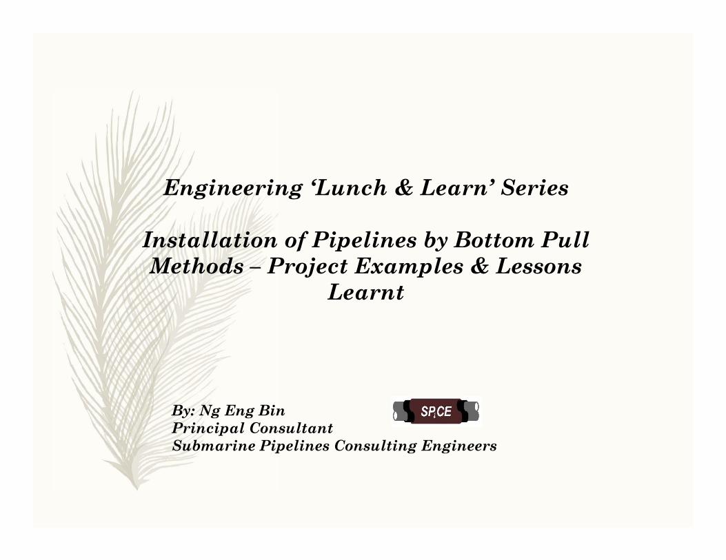
Project Example 1: Install bundle of 8 pipelines and 2 Fiber optic Cables from Bukom Island to Tanjong Penjuru @ mainland
Singapore
Tanjong Penjuru

Installation Concept: Build Pipeline Bundle at Bukom, then Bottom-pull across Shipping Channel to Penjuru, and Protect Bundle with Rock Berm

Preparatory Works prior to Bundle Pull

Stringing of Line Pipe to form Pipe Strings

Completed Pipe Strings Ready for Bundling prior to Bottom Pull
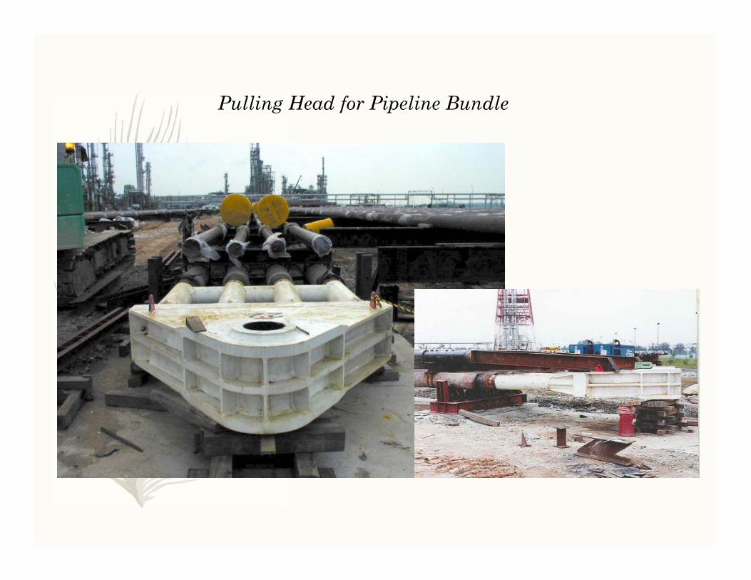
Pulling Head for Pipeline Bundle
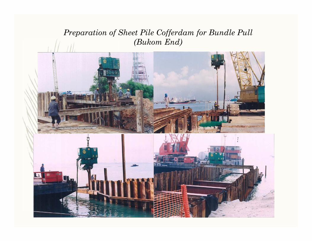
Preparation of Sheet Pile Cofferdam for Bundle Pull (Bukom End)

Preparation of Sheet Pile Cofferdam for Bundle Pull (Penjuru End)

Final preparation of cofferdam (Penjuru End)
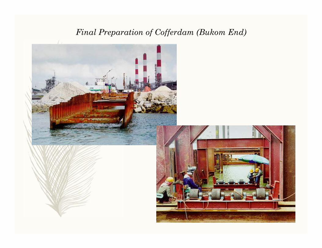
Final Preparation of Cofferdam (Bukom End)

‘Hold-back’ anchor concept for linear winch
Without hold-back anchor, linear winch will move towards the sea insteadof pipe moving towards the winch
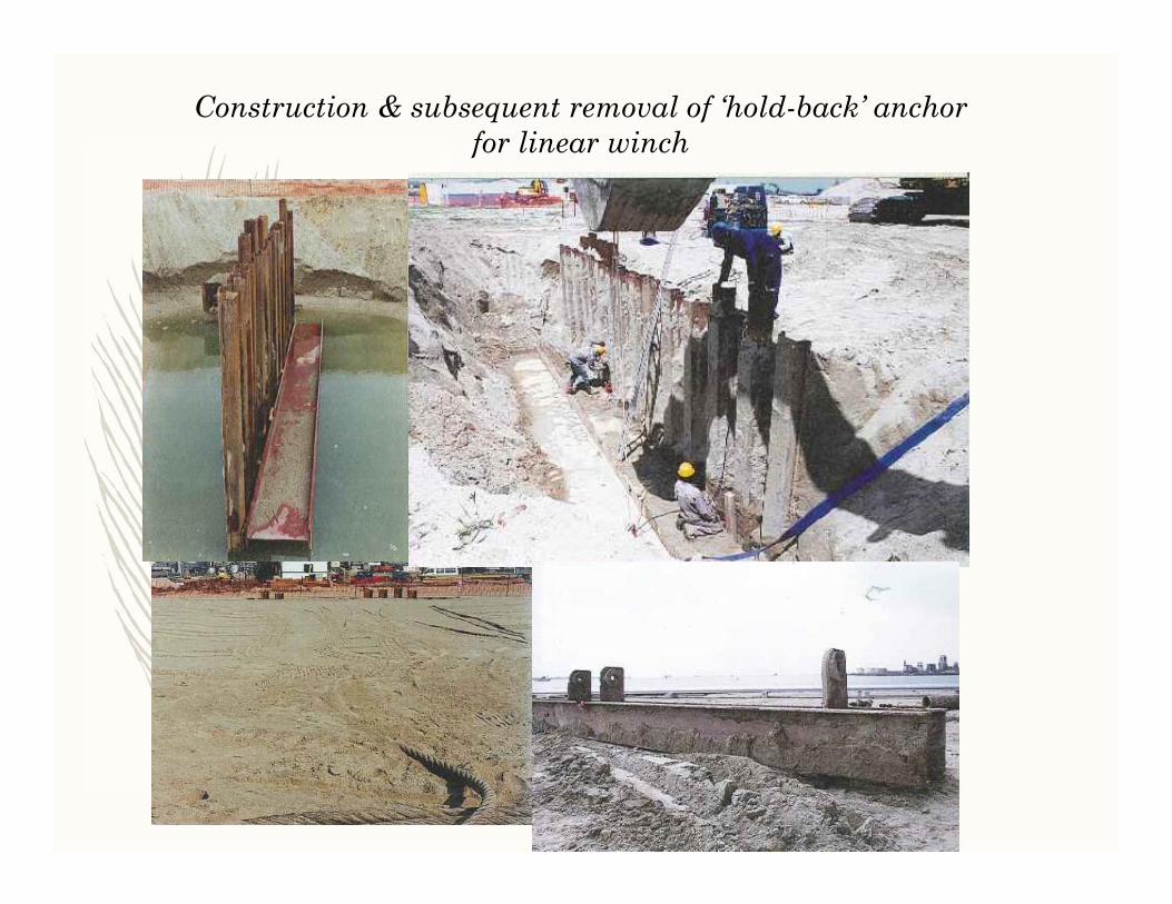
Construction & subsequent removal of ‘hold-back’ anchorfor linear winch
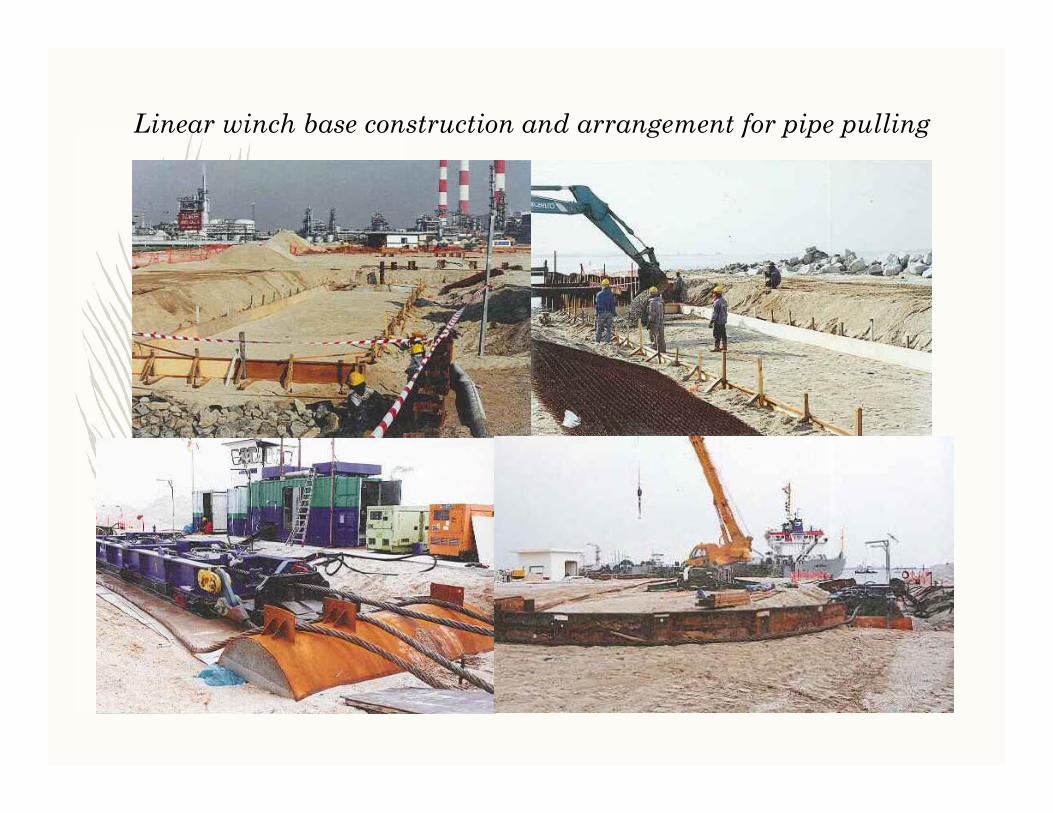
Linear winch base construction and arrangement for pipe pulling
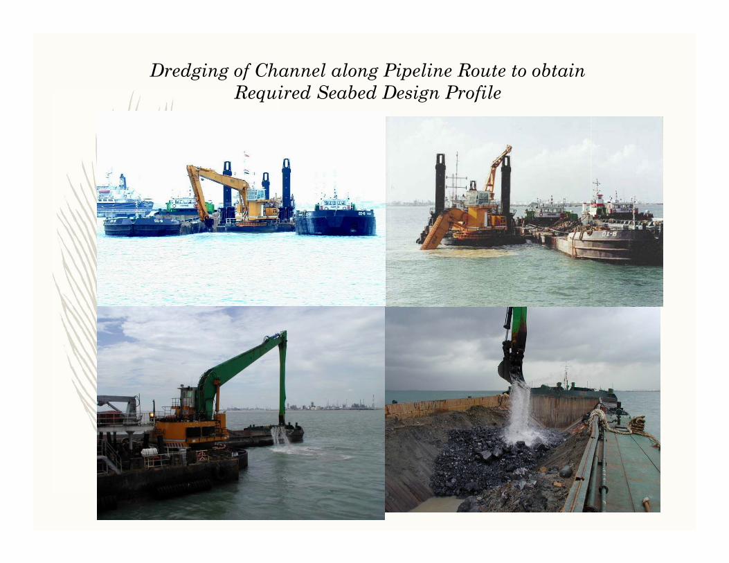
Dredging of Channel along Pipeline Route to obtainRequired Seabed Design Profile
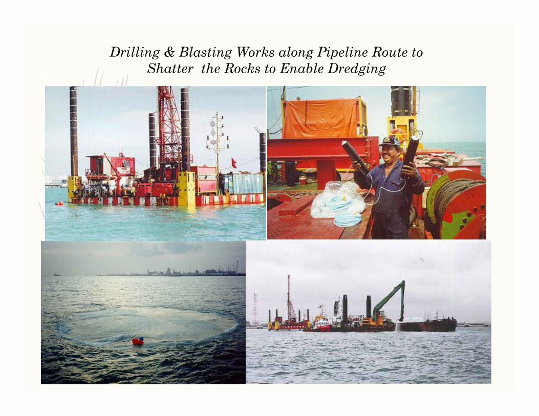
Drilling & Blasting Works along Pipeline Route to Shatter the Rocks to Enable Dredging

Due to Excessive Lengths of Rocks Requiring Blasting, a 2nd Blasting Spread was Used
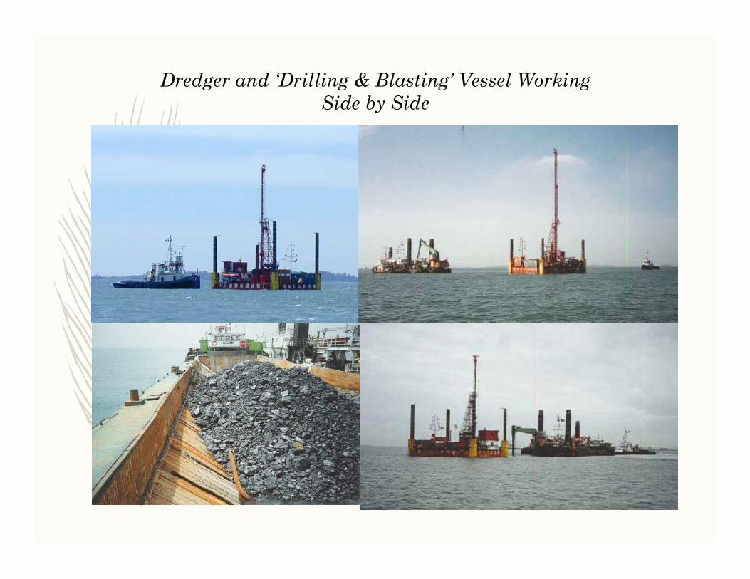
Dredger and ‘Drilling & Blasting’ Vessel WorkingSide by Side

Pulling Concept

Sheave Block which will be connected to Pipe Bundle Pulling Head
Sheave block enables effective pull force on pipe bundle to be double of the linear winch capacity

Manouvring Sheave Block for Connection to Pipe Bundle Pulling Head

Laying of twin wire (from sheave block) along pipeline route, thenterminating on lay vessel before connecting to ‘triplate’
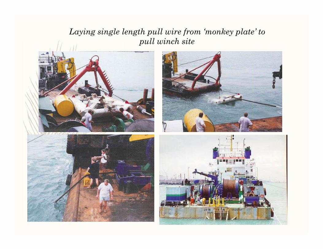
Laying single length pull wire from ‘monkey plate’ to pull winch site

Bundle Installation Across Sea Channel by Bottom Pull Method
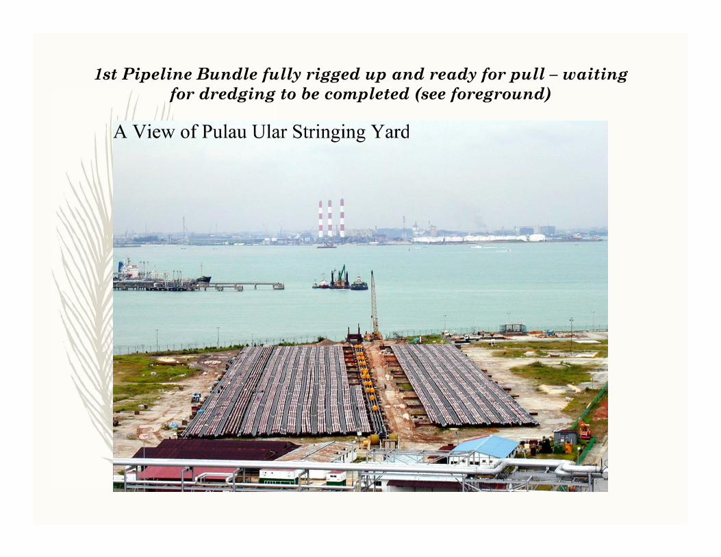
1st Pipeline Bundle fully rigged up and ready for pull – waitingfor dredging to be completed (see foreground)
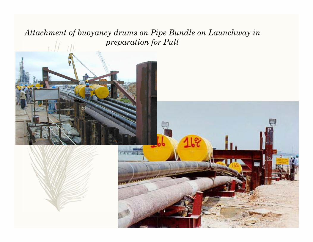
Attachment of buoyancy drums on Pipe Bundle on Launchway in preparation for Pull

Buoyancy tanks strapping arrangement on Pipeline Bundle
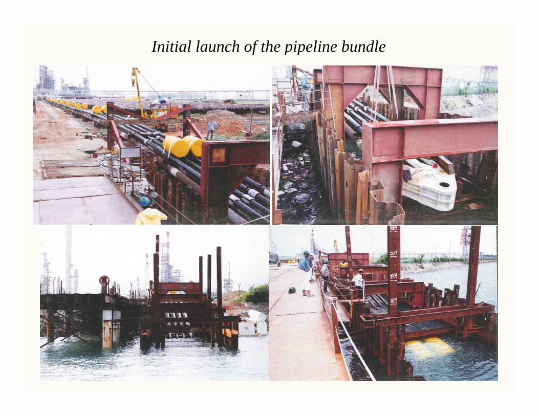
Initial launch of the pipeline bundle

Pipeline bundle ready for 1st launch (note: 2 team members associatedwith Intecsea – 3rd one was not at site ; guess who he is)
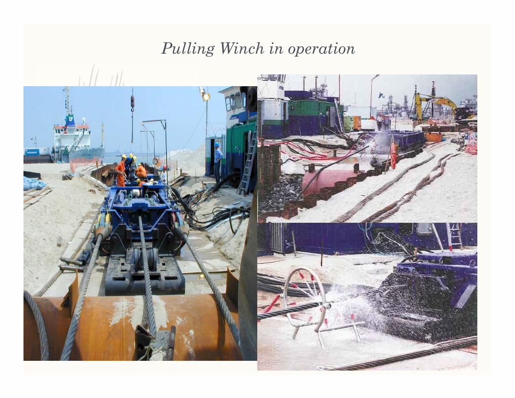
Pulling Winch in operation
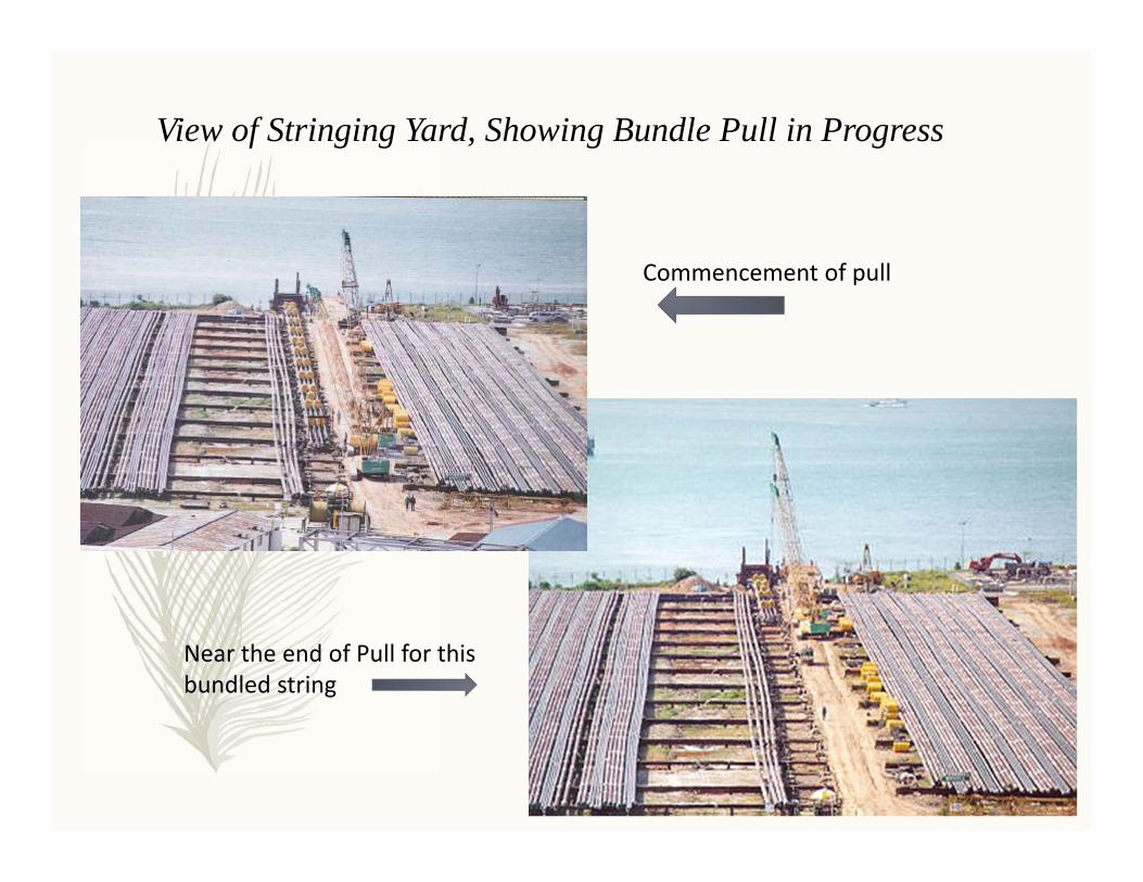
View of Stringing Yard, Showing Bundle Pull in Progress
Commencement of pull
Near the end of Pull for this bundled string

Alignment & tie-in of preceding bundle to the new bundle

Resumption of pipeline bundle pull after tie-in to preceding section
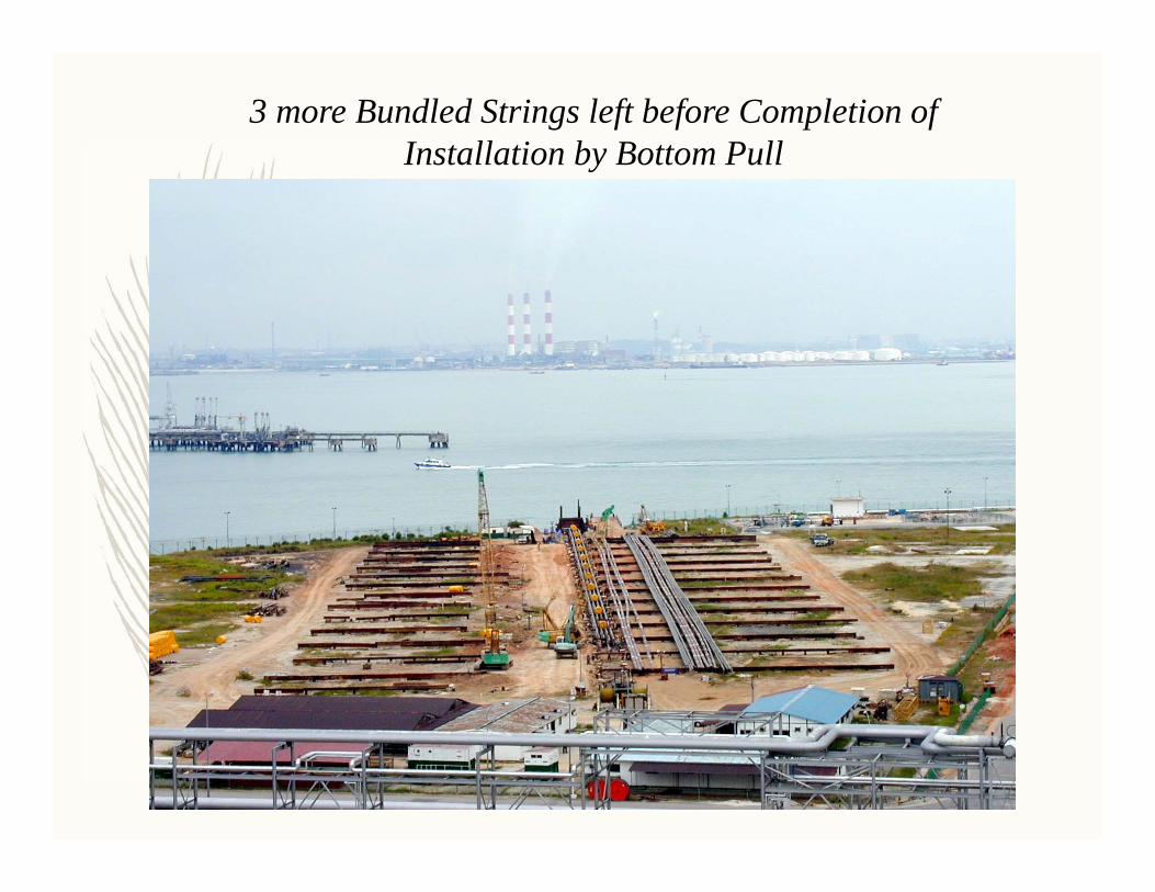
3 more Bundled Strings left before Completion of Installation by Bottom Pull
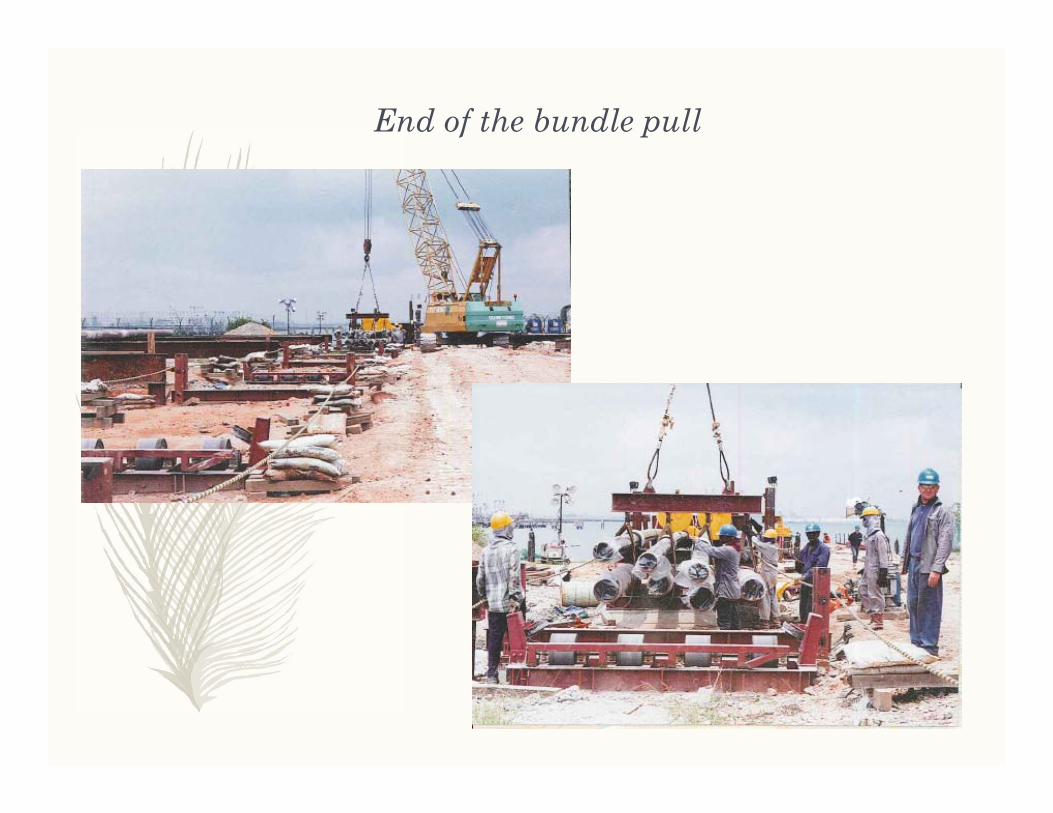
End of the bundle pull

Arrival of Pulling Head/Sheave Block at Destination Point

Installation of Risers on Pipeline Bundle
Rock dumping, pre-commissioning and site re-instatement

Transfer of quarry materials to site storage barge, and then to rock dumping vessel

Rock dumping by side stone dumping vessel
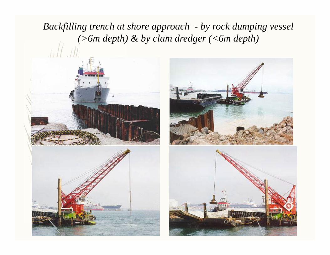
Backfilling trench at shore approach - by rock dumping vessel(>6m depth) & by clam dredger (<6m depth)

Flooding, gauging, cleaning & hydrostatic testing of pipeline bundle
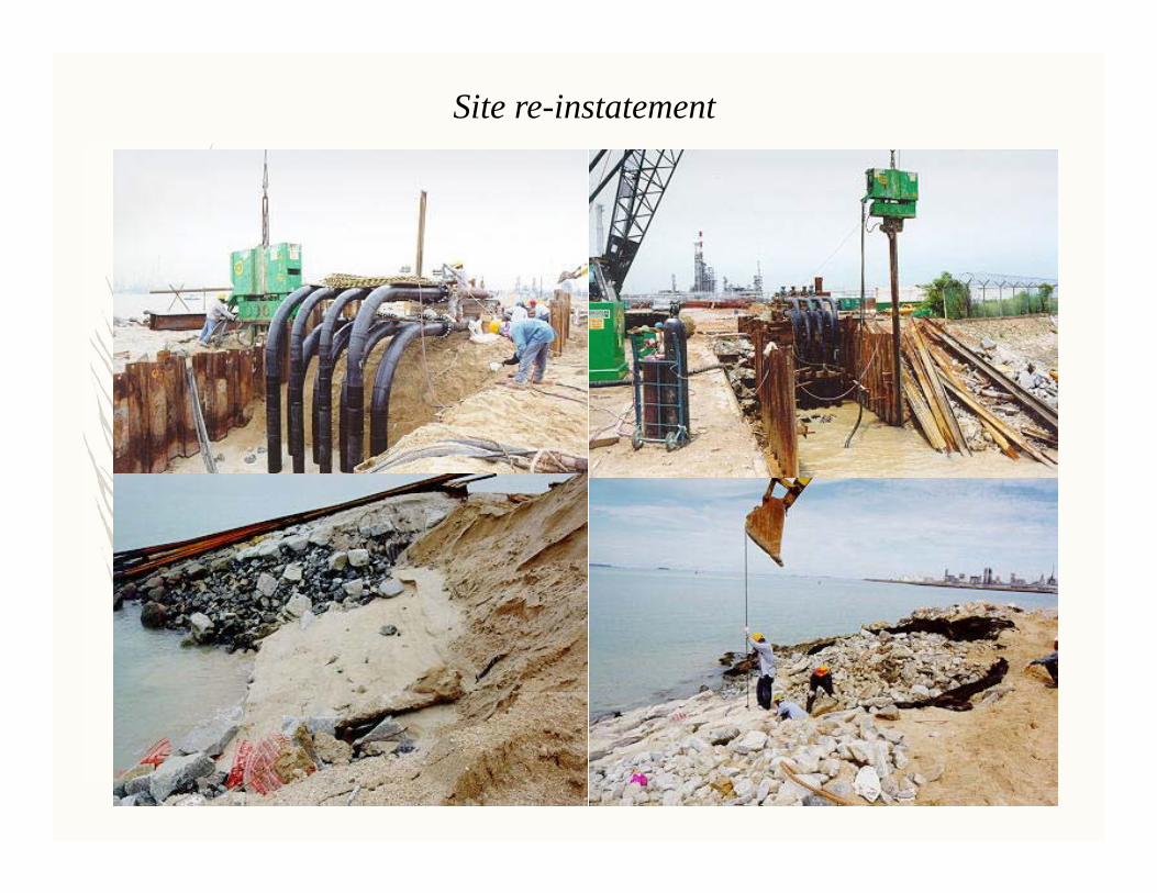
Site re-instatement

Site re-instatement (Cont’d)

Project Example 2: Install single pipeline from Landfall at Dahej to location 4.8km offshore & across 4.5km inter-tidal zone
(to discharge treated water from refinery through diffuser at pipe end to sea)S

Layout of stringing yard at Dahej – notice half cylindrical buoyancy tanks used (to maximise buoyancy during rising tide)

Linear pull winch arrangement on the stationary barge

Arrangement for transferring load from pull wire to hold-back anchor, & for winding up cable during pull

Initiation of pipe pull – pulling head transferred to intertidal zone by onshore equipment, then attached to pull cable

Typical pull during high tide (left) & view of pipe during receding tide when no pull could be made
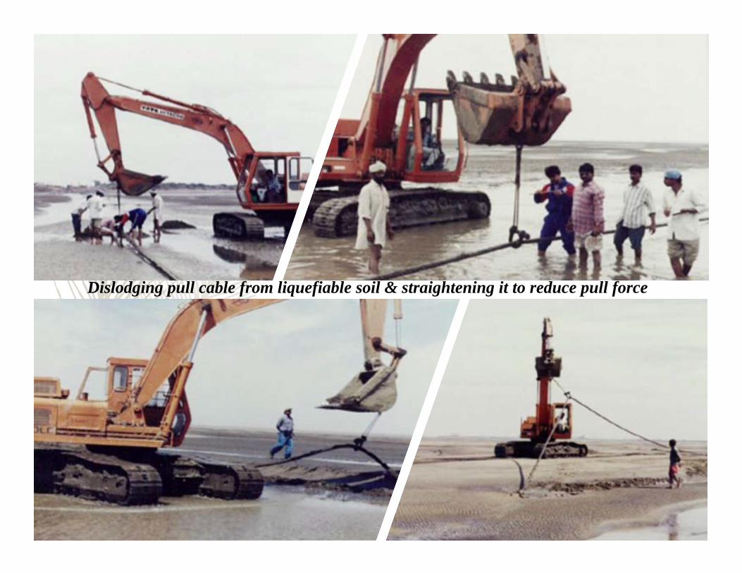
Dislodging pull cable from liquefiable soil & straightening it to reduce pull force
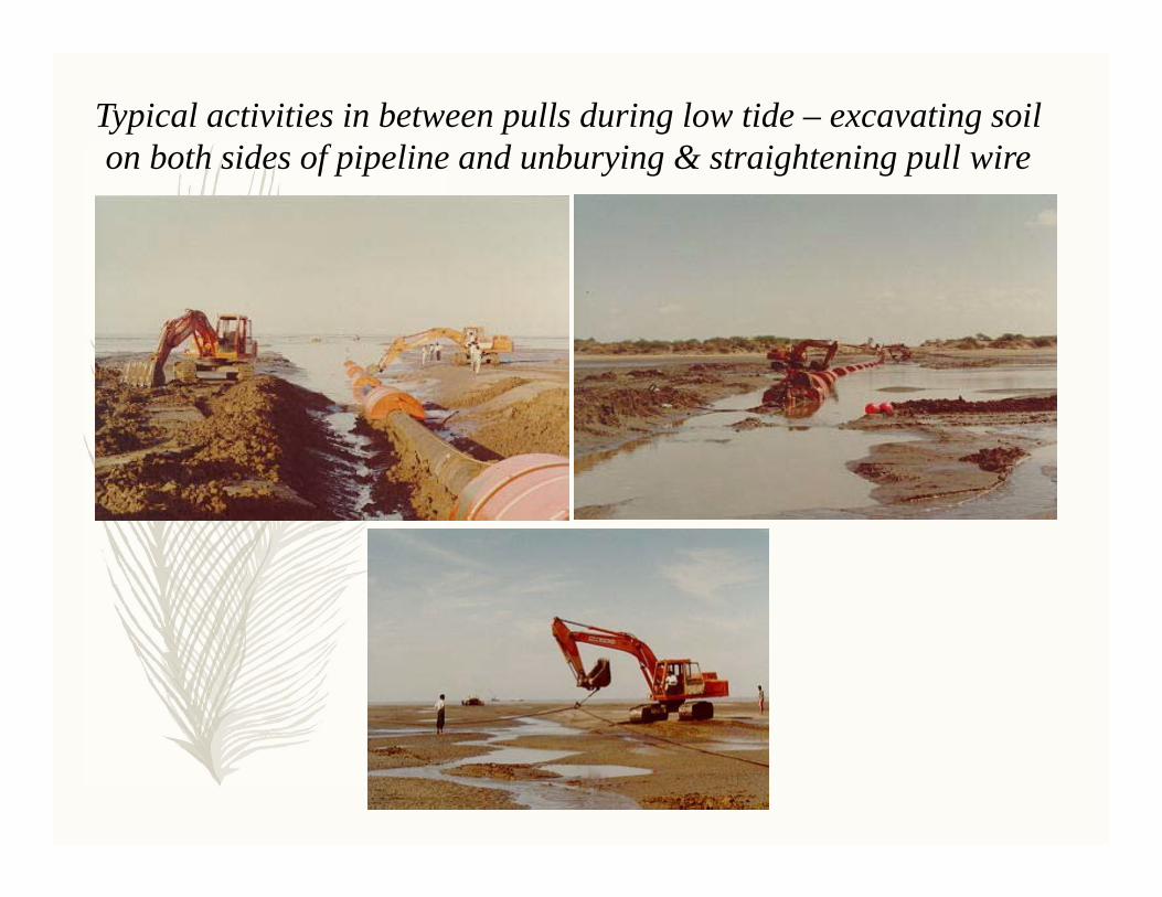
Typical activities in between pulls during low tide – excavating soil on both sides of pipeline and unburying & straightening pull wire
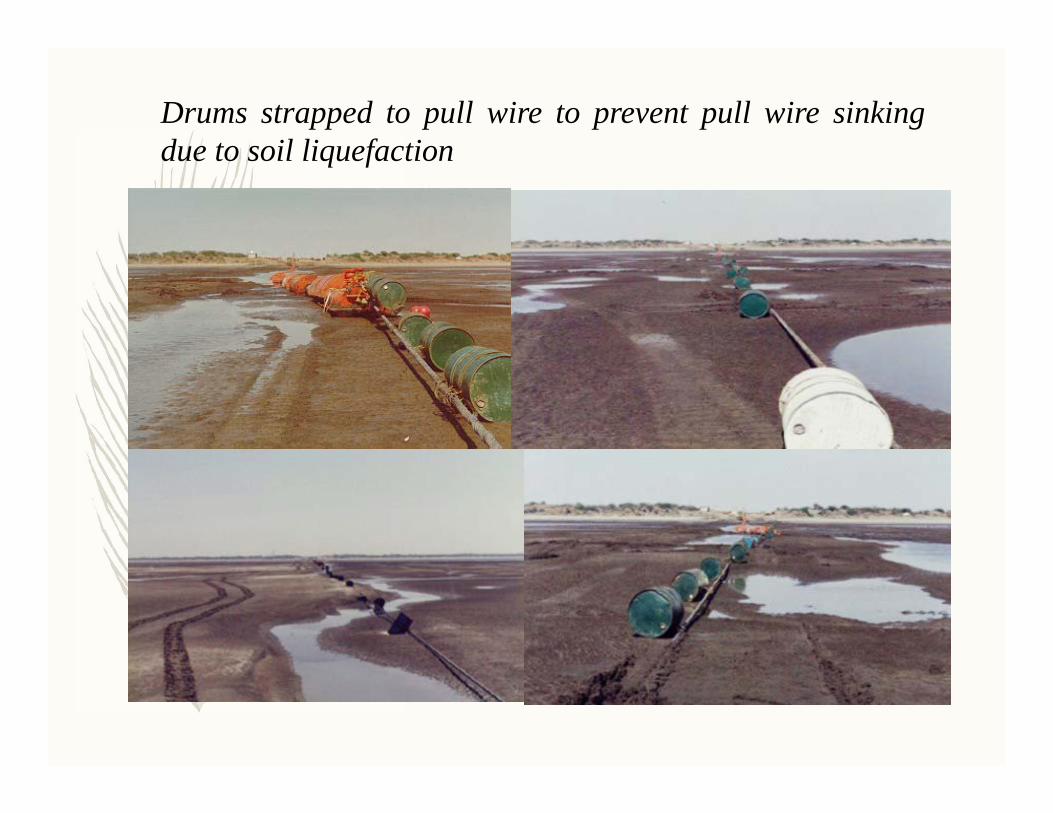
Drums strapped to pull wire to prevent pull wire sinkingdue to soil liquefaction

Welding of new pipe string to preceding string during low tide

Discovery of ‘deflected’ pipeline after pipe pull the night before –the result of reduction in buoyancy spacing unilaterally taken by onshore site supervisor
Buckle occurred mid‐point of deflected pipe section

• As a result of pipe buckle and inability to pull back the pipeline to repair, pipeline was severed off at buckle location.
• Pipeline was capped at the ‘shore end’ and partial pipeline pulled to destination.
• A second segment was pulled until the pulling head just crosses the trailing end of preceding section.
• Both ends lifted off seabed and tied-in (see picture below)
Execution of Plan B – Splitting pipelaying to 2 sections
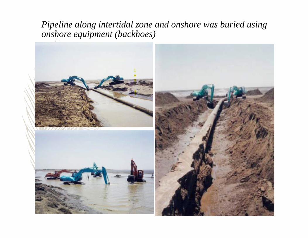
Pipeline along intertidal zone and onshore was buried using onshore equipment (backhoes)

Offshore pipeline was buried using a jetsled (white tiger)
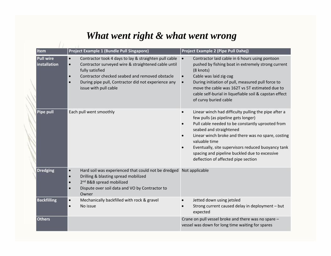
What went right & what went wrongItem Project Example 1 (Bundle Pull Singapore) Project Example 2 (Pipe Pull Dahej)
Pull wire installation
Contractor took 4 days to lay & straighten pull cable Contractor surveyed wire & straightened cable until
fully satisfied Contractor checked seabed and removed obstacle During pipe pull, Contractor did not experience any
issue with pull cable
Contractor laid cable in 6 hours using pontoon pushed by fishing boat in extremely strong current (8 knots)
Cable was laid zig‐zag During initiation of pull, measured pull force to
move the cable was 162T vs 5T estimated due to cable self‐burial in liquefiable soil & capstan effect of curvy buried cable
Pipe pull Each pull went smoothly Linear winch had difficulty pulling the pipe after a few pulls (as pipeline gets longer)
Pull cable needed to be constantly uprooted from seabed and straightened
Linear winch broke and there was no spare, costing valuable time
Eventually, site supervisors reduced buoyancy tank spacing and pipeline buckled due to excessive deflection of affected pipe section
Dredging Hard soil was experienced that could not be dredged Drilling & blasting spread mobilized 2nd B&B spread mobilized Dispute over soil data and VO by Contractor to
Owner
Not applicable
Backfilling Mechanically backfilled with rock & gravel No issue
Jetted down using jetsled Strong current caused delay in deployment – but
expectedOthers Crane on pull vessel broke and there was no spare –
vessel was down for long time waiting for spares

For a successful pipe pull project, it is advisable to stick to thefollowing guidelines:1. Use a linear winch or similar that can provide constant pull. Waterfall
winches are not suitable as the pull capacity reduces as the wire iswinched onto the drums.
2. Use supplementary buoyancy device to reduce the required pullforce, but it should be used with caution.• On-bottom stability of the pipeline should be considered when
determining the amount of buoyancy device to use, andunstable pipe can result in undesirable pipe movement duringand after the pull, and as demonstrated in an earlier example,could lead to pipe damage.
3. Choose a winch that has excess capacity over what is deemedrequired based on engineering calculations. In general, there shouldbe a comfortable level of safety factor for all equipment used at site.
Lessons’ Learnt
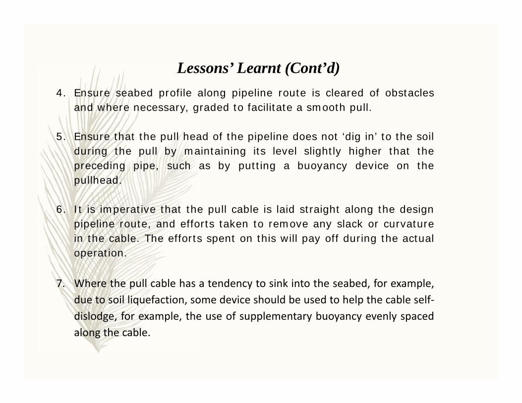
4. Ensure seabed profile along pipeline route is cleared of obstaclesand where necessary, graded to facilitate a smooth pull.
5. Ensure that the pull head of the pipeline does not ‘dig in’ to the soilduring the pull by maintaining its level slightly higher that thepreceding pipe, such as by putting a buoyancy device on thepullhead.
6. It is imperative that the pull cable is laid straight along the designpipeline route, and efforts taken to remove any slack or curvaturein the cable. The efforts spent on this will pay off during the actualoperation.
7. Where the pull cable has a tendency to sink into the seabed, for example,due to soil liquefaction, some device should be used to help the cable self‐dislodge, for example, the use of supplementary buoyancy evenly spacedalong the cable.
Lessons’ Learnt (Cont’d)

8. Checks should be made of the pipeline route prior to pipe pull toensure that there is no debris or obstruction to the pipe pull.
9. Maintain healthy level of spares at site for all equipment,especially for major equipment, such as for pull winch(es) andcranes.
10.Learn from lessons of past projects (including those from othercontractors) and implement all applicable lessons from pastprojects to the new project being planned or executed.
Lessons’ Learnt (Cont’d)
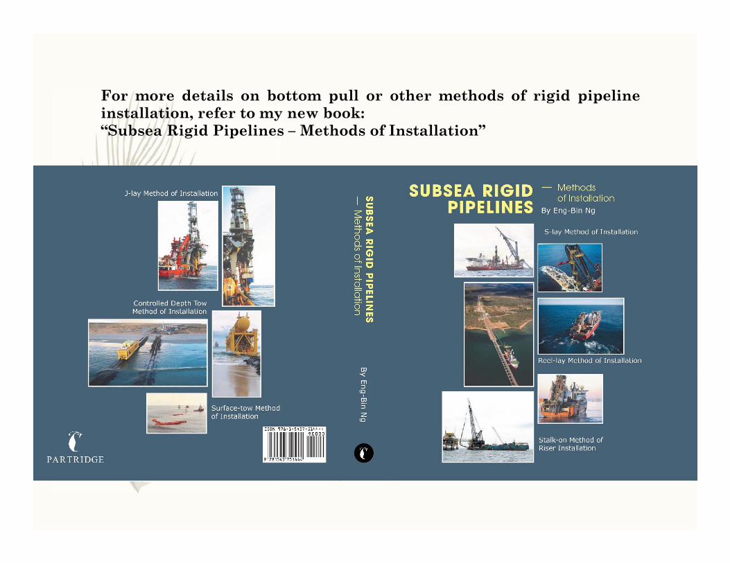
For more details on bottom pull or other methods of rigid pipelineinstallation, refer to my new book:“Subsea Rigid Pipelines – Methods of Installation”

QUESTIONS ????

Production of Rocks for Pipeline Protection

Extraction of rocks at Quarry by drilling & blasting
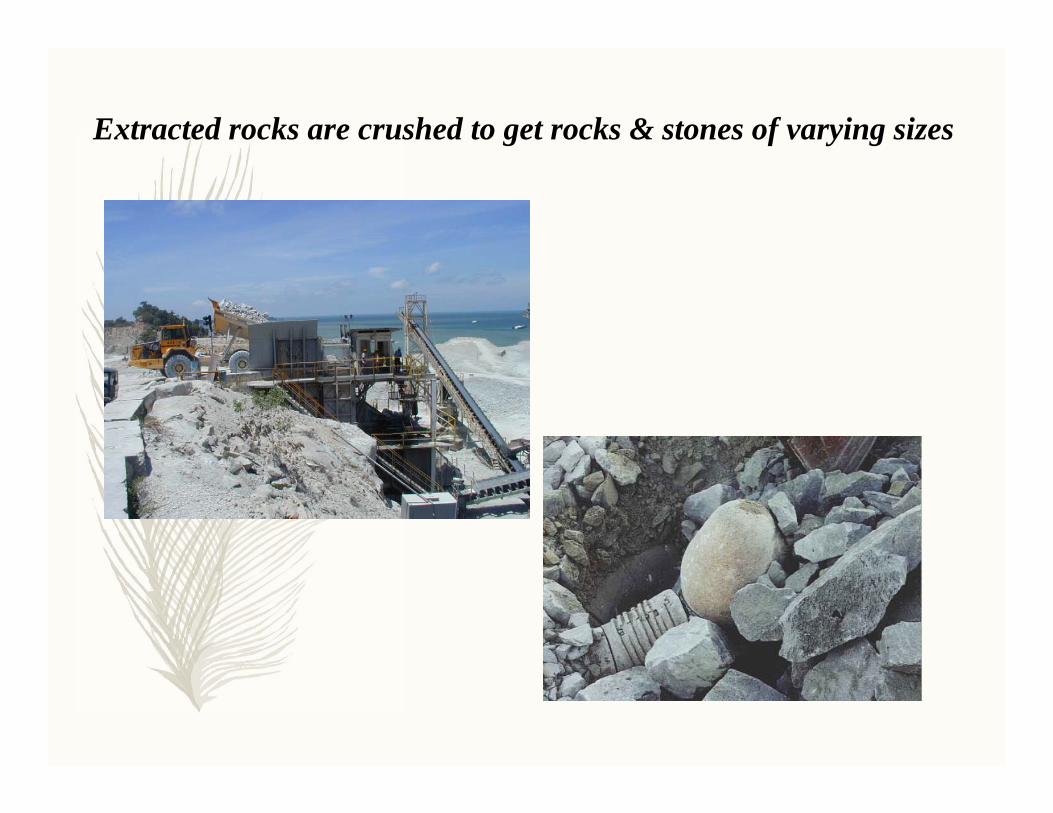
Extracted rocks are crushed to get rocks & stones of varying sizes
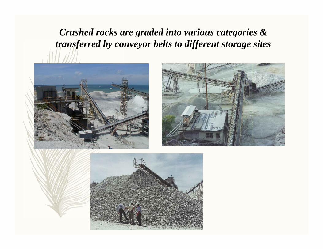
Crushed rocks are graded into various categories & transferred by conveyor belts to different storage sites
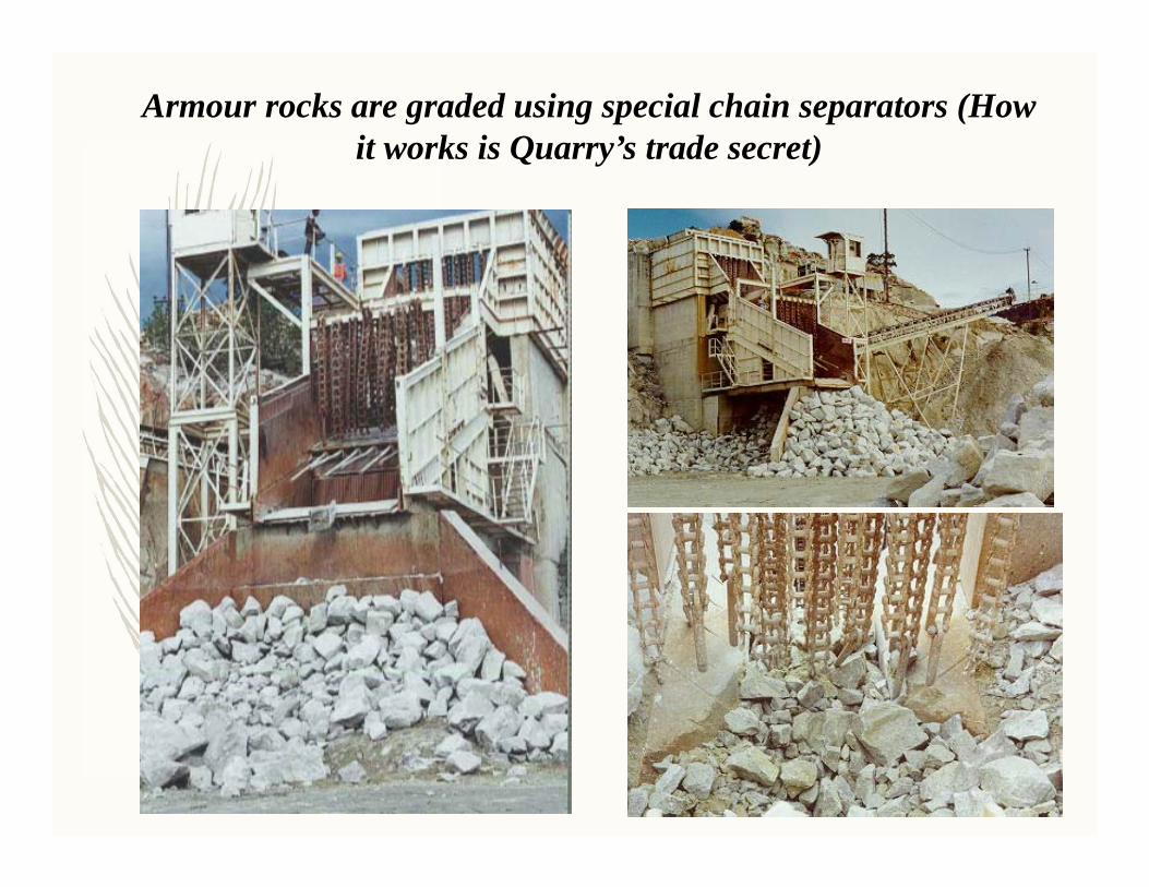
Armour rocks are graded using special chain separators (How it works is Quarry’s trade secret)
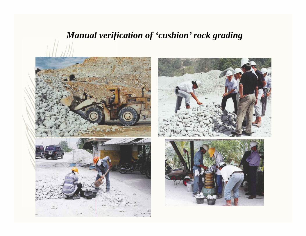
Manual verification of ‘cushion’ rock grading
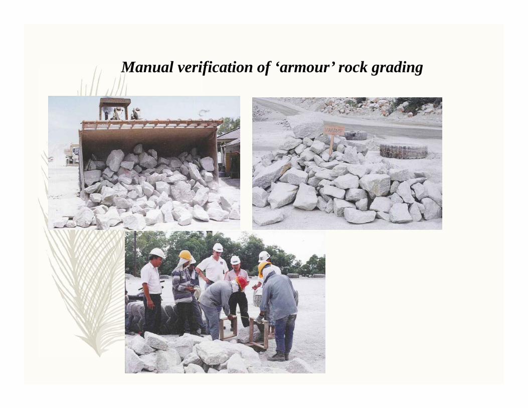
Manual verification of ‘armour’ rock grading

Load-out and transportation of engineered rocks to construction site


![Industrial Push-Pull Open Shelving Compactors - Industrial... · 2018. 4. 6. · Bottom Track - Push Pull - Open Shelving Concept Only for narrow rooms / corridors & wall touch. [6]](https://static.fdocuments.in/doc/165x107/60448ec09c2b86135d0ed76c/industrial-push-pull-open-shelving-compactors-industrial-2018-4-6-bottom.jpg)