
Boosting the Concept of Topography Optimized Parts
14
Boosting the Concept Boosting the Concept of Topography Optimized Parts of Topography Optimized Parts Rodrigo BENEVIDES Rodrigo BENEVIDES Simulation Engineer Simulation Engineer Valeo Powertrain Thermal Systems Valeo Powertrain Thermal Systems – – La Verri La Verri è è re (France) re (France) Altair HTC Congress – November 2011
-
Upload
altair-engineering -
Category
Technology
-
view
427 -
download
1
Transcript of Boosting the Concept of Topography Optimized Parts

Boosting the ConceptBoosting the Conceptof Topography Optimized Partsof Topography Optimized Parts
Rodrigo BENEVIDESRodrigo BENEVIDESSimulation EngineerSimulation EngineerValeo Powertrain Thermal Systems Valeo Powertrain Thermal Systems –– La VerriLa Verrièère (France)re (France)
Altair HTC Congress – November 2011

II
The Valeo Group
New Organization� Powertrain Systems
� Comfort and Driving Assistance Systems
� Visibility Systems
� Thermal Systems– Climate Control
– Powertrain Thermal Systems
– Compressors
– Front-End Module
Global Presence
Climate Control Compressors Front-End ModulePowertrainThermal Systems

II
Introduction
Motivation� Reducing time to market = being competitive
Objective� To decrease the product development time
How� Implementing structural optimization simulation and adapt its
usage to the company teams structure
� Making methodologies to apply the best practices
Object of this Study� Water Charger Air Cooled part made of a constant thickness
aluminum plate

II
Simulation Model
Constrained Edges
Internal Pressure
Constant Thickness
Zone of Allowable Changes
Water Charger Air Cooled
Stress Criterion < Fatigue limit (called F in this presentation)

II
2.07 F
Trial & Error Process
ProductConcept
TraditionalSimulation
OK!Approved?YESYES
NONO
1.10 F
Additional Solution : .Increase the ThicknessIncrease the Thickness
... $ $ $ $ $ $ .
-47%
InitialInitialDesignDesign After TrialAfter Trial
and Errorand Error
FatigueLimit (F)
many loopsmany loops
x F x F
II
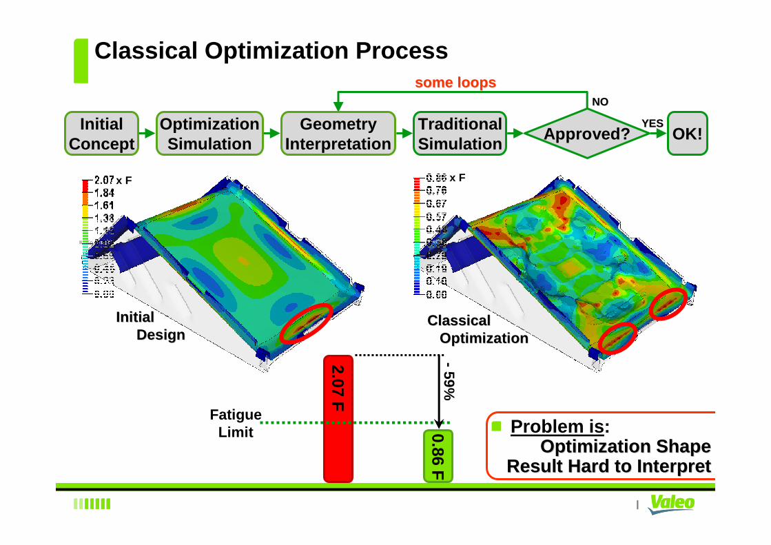
Classical Optimization Process
TraditionalSimulation
OK!Approved?YESYES
NONO
InitialConcept
OptimizationSimulation
GeometryInterpretation
2.07 F
0.86 F
FatigueLimit Problem is : .
Optimization Shape Optimization Shape Result Hard to InterpretResult Hard to Interpret
-59%
InitialInitialDesignDesign
ClassicalClassicalOptimizationOptimization
some loopssome loops
x F x F

II
Topography Optimization Result
Designer has difficulty to interpret the shape got directly from the optimization
Mesh treatment is needed to deliver a geometry easier to be interpreted.

II
Interpretation by OSSmooth
OriginalOriginalMeshMesh
AfterAfterOSSmoothOSSmooth

II
Interpretation by Shell Offset
OriginalOriginal
1x Offset procedure1x Offset procedure
2x Offset procedure2x Offset procedure
3x Offset procedure3x Offset procedure
3) Offset positive
4) Offset negative
1) Half thicknessSteps :
2) CFD corners

II
x F x F x Fx F
Tested Mesh Treatment
OSSmoothOSSmooth OSSmooth + OSSmooth + Shell OffsetShell Offset
Shell OffsetShell OffsetNo treatmentNo treatment
0.78 F
1.13 F
+ 42%+ 42% + 11%+ 11%-- 2%2%0.80 F
0.88 F

II
InitialInitialDesignDesign
Optimization Process with Mesh Treatment
InitialConcept
TraditionalSimulation
OK!Approved?OptimizationSimulation
GeometryInterpretation
MeshTreatment
2.07 F
0.85F
0.82F
FatigueLimit (F)
-59%
-61%
TreatedTreatedMeshMesh
FinalFinalDesign AidedDesign Aided
by Treated Meshby Treated Mesh
x F
x Fx F

II
FinalFinalDesign AidedDesign Aided
by Treated Meshby Treated Mesh
Trial & ErrorTrial & ErrorDesignDesign
Final Comparison
InitialInitialDesignDesign
Max Stress = 2.07 F
Max Stress = 1.10 FAbove Stress LimitTime = 12 days
Max Stress = 0.82 FTime = 3 days
–– 61% in Stress61% in Stress
–– 47% in Stress47% in Stress
–– 26% in Stress26% in Stress
4 times faster4 times faster

II
Conclusion
Trial and Error way of designing was time consuming and did not lead to good results.
The mesh treatment made the geometry interpretation easier than by using the result got directly from t he optimization iteration.
In this study, treating the mesh by Offsets resulte d in lower stress comparing to the OSSmooth method.
Teams must work together. In this process, some additional tasks can be implemented, but in the end the global time of the product development is reduced, and the quality improved.