
Book of services - iLumTech · Book of services. 4 I WHO WE ARE WHO WE ARE I 5 WHO WE ARE iLumTech...
55
Book of services
Transcript of Book of services - iLumTech · Book of services. 4 I WHO WE ARE WHO WE ARE I 5 WHO WE ARE iLumTech...

Book of services

I 5 4 I WHO WE AREWHO WE ARE
WHO WE ARE
iLumTech has more than 15 years of experience in the research and de-velopment of luminaires and all connected design and engineering services. Thanks to wide-ranging experience, NDA approach, and access to the most advanced technical and development equipment, iLumTech can offer flexible and professional support for a large variety of customers.
The quality of our services is guaran-teed by the capability and education of our international team of more than 60 designers and engineers, who receive regular training on the latest trends and standards. The sustained improvement of our laboratories and technologies also ensures that our customers will be satisfied with the implementation of the latest trends in the provided services and development.
WHAT WE OFFER• FLEXIBLE AND PROFESSIONAL DESIGN AND SERVICE SUPPORT FOR CUSTOMERS FROM VARIOUS INDUSTRIES• STABLE AND RELIABLE PARTNERSHIP FOR CUSTOMERS AND THE DEVELOPMENT OF THEIR PRODUCTS• INTERNATIONALLY TRUSTED PROVISION OF NEW SOLUTIONS AND INNOVATIONS• A FOUNDATION FOR THE DEVELOPMENT OF A UNIQUE NETWORK OF TECHNOLOGICALLY FUTURE-ORIENTED COMPANIES• A LISTENING EAR FOR CUSTOMER NEEDS THAT WE SATISFY BY USING THE LATEST TECHNOLOGIES AND FOLLOWING THE LATEST TRENDS
FULL LUMINAIRE DEVELOPMENT We provide solutions for luminaire manufacturers that cover everything from concept to release of the product to the market. Within the framework of these solutions, we deliver comprehen-sive services across industrial, optical, thermal, electronic, and mechanical design, all of which are supported by excellent supply-chain management, full system testing, and prototyping.
DESIGN & ENGINEERING SERVICES We are home to experienced experts from many fields who enable us to support customers with a wide range of individual design and engineering services. If you require industrial design, optical design, thermal evaluation, elec-tronic solutions or even the development of entire products, our team can provide a perfectly tailored solution. We also offer mechanical engineering and cus-tomisation services that ensure that even the smallest details are taken care of.
LABORATORY SERVICES We have some of the best-equipped laboratories in Europe and can provide customers with an array of optical, thermal, electronic, and mechanical tests side-by-side with other services. A par-ticular advantage of this is that we can perform tests on final prototypes, assur-ing customers of positive results through-out development and during certification.
FURTHER OEM SUPPORT We offer customers the option to continue with the manufacture of devel-oped luminaires, optical systems, and electronic solutions at trusted facilities close to our company.
PROPRIETARY COMPONENTS & DEVICES FOR THE LIGHTINGMARKET We bring to the market a range of unique lighting control devices under the brand name Connected Lighting, as well as original Optical Solutions and LED Units. All are suitable for a variety of customers including lighting and com-ponents manufacturers, distributors, wholesalers, installation companies, and end-users.

FULL LUMINAIRE DEVELOPMENT
PRODUCT DEVELOPMENT REQUEST
TECHNICAL & COMMERCIAL NEGOTIATION & AGREEMENT
DEVELOPMENT STAGES
PRODUCT COMPLETION & CERTIFICATION
AFTER-SALES SERVICES
FULL LUMINAIRE DEVELOPMENT

FULL LUMINAIRE DEVELOPMENT Not every company has the time, capacity or resources to develop a new
luminaire in-house. That’s where we can help. We make it our business to
support your business. By listening to your needs and understanding your busi-
ness’s marketplace, we can best apply our knowledge and experience to de-
velop a final product that will give you a competitive advantage, save your time,
and reduce your costs.
“Perfection has to do with the end product,
but excellence has to do with the process.” Jerry Moran

I 11 10 I PRODUCT DEVELOPMENT REQUESTFULL LUMINAIRE DEVELOPMENT
PRODUCT DEVELOPMENT REQUEST
The first input we have from you, as a customer, is the specification of your request. So that we know exactly what you want, we will ask you to fill in a product development form. A deeper understanding of your specifica-tions, aims, and market positioning will be gained from direct discussion, where we can also get to know each other a little better.
PRODUCT DEVELOPMENT REQUEST
TECHNICAL & COMMERCIAL NEGOTIATION & AGREEMENT
DEVELOPMENT STAGES
PRODUCT COMPLETION &CERTIFICATION
AFTER-SALES SERVICES
LET US KNOW WHAT YOU NEED• WHAT KIND OF PRODUCT DO YOU WANT?• WHERE WILL IT BE USED?• DO YOU HAVE A MARKET AND PRICE IN MIND?• HOW FAST DO YOU NEED IT?• WHAT ARE YOUR PRODUCTION REQUIREMENTS AND VOLUMES?• WHAT ABOUT DOCUMENTATION AND CERTIFICATION?
TECHNICAL REQUIREMENTS To help us evaluate your request and prepare price offers for the product it-self, and for engineering and tooling ser-vices if required, we need to understand exactly what you wish to develop from a technical point of view, including the intended application of the luminaire.
MATERIAL & SHAPE SPECIFICA-TION The first step in defining a product is selecting the kind of shape and colour you’d like and the material you want it to be made from. Also, tell us your requirements for mounting and other parameters such as IP/IK ratings and op-erating ambient temperatures?
OPTICAL REQUIREMENTS The optics of a luminaire are core to its functional and commercial success. We need to know what LIDC you need, illumination requirements, whether you want direct, indirect or combined flux, and if there are specific glare considera-tions to take into account. To precisely define these parameters, we will ask you for a desired lumen output, UGR value, beam angle, luminance value, and what type of optics you’d prefer.
LED REQUIREMENTS Surely you also have in mind what type of LEDs you would like to include in your product. What CCT and CRI do you need? How strict are your MacAdam step requirements? Do you have a de-sired wattage, and what type of system efficacy would you like to achieve?
ELECTRONIC PARAMETERS We are happy to include any type of control system you wish into your product. This is not limited to dimming and emergency units, but also includes the option to incorporate independent control of direct and indirect flux, RGB lighting, and Tunable White (we have a range of Tunable White modules that could be interesting to you). Just let us know what norms the luminaire must fulfil, the electric class required, if there are flammability considerations, and if there are any specific tests or certifi-cates you wish us to provide.
COMPONENT SPECIFICATION If you have any particular require-ments regarding components you want to use, just let us know in advance, and we will be sure to smoothly implement them into the design.
COMMERCIAL CONDITIONS Before investing in the development and engineering of a new product, it is important to set a target market price, which will define your limits in terms of total cost of creation. There are many other commercial conditions to also consider, such as warranty, launch date, required volume, and the number of prototypes you would like during devel-opment. We can also continue with the manufacture of your product in partner-ship with trusted local businesses.
VISUALS Please share with us any materials you have that will help us fully understand your vision. For example, show us your current and previous products, what has inspired you, the benchmarks you wish to meet, and even your own hand drawn sketches. This will speed up initial discus-sions and ensure there are no misunder-standings about exactly what you want.

I 13 12 I FULL LUMINAIRE DEVELOPMENT TECHNICAL & COMMERCIAL NEGOTIATION & AGREEMENT
TECHNICAL & COMMERCIAL NEGOTIATION & AGREEMENT
Successful partnerships and products depend on good preparation and continued open communication. To avoid unnecessary issues at a later stage, we begin development with a meeting where we discuss our in-depth offer that includes detailed specification of services and schedules.
PRODUCT DEVELOPMENT REQUEST
TECHNICAL & COMMERCIAL NEGOTIATION & AGREEMENT
DEVELOPMENT STAGES
PRODUCT COMPLETION &CERTIFICATION
AFTER-SALES SERVICES
WHAT OUR OFFER INCLUDES• AN INITIAL DESIGN PROPOSAL• A PRICE OFFER BASED ON ENGINEERING AND TOOLING REQUIREMENTS• A DESCRIPTION OF THE DEVELOPMENT STAGES• SCHEDULES AND MILESTONES• EVALUATION OF ADDITIONAL COSTS• A DEVELOPMENT CONTRACT• A PRODUCTION CONTRACT, IF REQUIRED
PRODUCT SPECIFICATION & PROPERTIES DEFINITION We will help you complete the product definition form. All technical issues are evaluated, re-evaluated and optimised during project meetings, at which the responsible persons for your project from each R&D department and the commercial team will be present. During the product definition phase, we will encounter our first obstacles, to which we will endeavour to find suitable solutions to prevent delay later in the development process. Every discussed detail will be recorded in your product definition documentation and sent to you to double check. This gives you added assurance that the foundation we build upon is precisely according to your wishes.
COST & TIME SCHEDULE EVALUATION Based on the final definition, we will prepare a time schedule containing pro-ject milestones. You can discuss your feel-ings about the project based on the doc-umentation provided at these milestones. You will also receive a cost evaluation, which is the quote divided according to development costs and tooling expenses. Commercial conditions, including the price and payment conditions, along with the schedule, are part of the overall de-velopment contract as well as the signed product development form.
DEVELOPMENT CONTRACT The result of the technical and com-mercial negotiation and agreement pro-cess is the final development contract and confidentiality agreement. Here, all conditions and the commencement date of development are stated.

I 15 14 I DEVELOPMENT STAGESFULL LUMINAIRE DEVELOPMENT
DEVELOPMENT STAGES
PRODUCT DEVELOPMENT REQUEST
TECHNICAL & COMMERCIAL NEGOTIATION & AGREEMENT
DEVELOPMENT STAGES
PRODUCT COMPLETION &CERTIFICATION
AFTER-SALES SERVICES
NOW THE ENGINEERING BEGINS• INDUSTRIAL DESIGN• OPTICAL DESIGN• THERMAL DESIGN• ELECTRONIC DESIGN• MECHANICAL ENGINEERING• PROTOTYPING• MEASUREMENT AND TESTING• TOOLING• PRODUCTION (ON REQUEST)
ENGINEERING Luminaire development begins with industrial design: a process of creating 3D designs using 3D modelling soft-ware that allows us to implement any adjustments you wish immediately. We can also prepare non-functional mock-ups for better analysis of the aesthetic features of the product. After the indus-trial design is confirmed, we will con-tinue further with optical, thermal and electronic design, and finally with me-chanical engineering. Optical and ther-mal design is based on the preparation of simulations and selection of materials and cooling systems. The departments must work closely together to fine-tune proposals according to achieved simu-lated values. Electronic design involves creation of PCB designs and suggestion of the most suitable components for electronic schemes. If desired, we can also implement suitable software and interfaces, or even design new ones, to enable simple and flexible control of your product. And lastly, the mechani-cal engineers prepare sheet metal, die cast, and extrusion designs appropriate to the type of product. They must en-sure that all desired mechanical proper-ties are provided, especially in the case of requested IP/IK protection.
FINAL DOCUMENTATION Once the engineering stages are complete, we will provide you with com-prehensive documentation that acts as the base for creation of prototypes to be tested in our laboratories.
PROTOTYPING & EVALUATION What type of prototype we use for testing and evaluation depends on the kind of luminaire and what materials it is made from. We have the possibility to use 3D printing to produce a prototype that can be tested as a final product from an optical point of view. If the prototype is produced from milled aluminium, it is also possible to test the thermal, elec-tronic and mechanical aspects. All re-sults are shared with you and evaluated against the product definition form.
TOOLING As soon as you give us approval of the final documentation and prototype, we will move on to the tooling stage. This involves the production of die casts, extrusion tools, or injection moulds. Tool production is regularly controlled by us to avoid further issues, including the evaluation of tool prototypes, and any necessary optimisation. The final tools are also measured and the results sent to you and assessed by our engineers.
PROJECT PREPARATION
DESIGN
PROTOTYPING
PRE-SERIES, KICK-OFF & CERTIFICATION
PRODUCT DEFINITION• Product definition form
INDUSTRIAL DESIGN• Form and shape definition
PREPARATION• Tooling production• Prototype production
PRE-PRODUCTION PLANNING• Pre-production• Datasheets and manuals
DEVELOPMENT CONDITIONS• Time schedule• Milestones
OPTICAL DESIGN• Optical solution• Optical measurements and evaluation
MEASUREMENTS• Thermal, photometric, EMC, mechanical and electrical safety tests
PRE-PRODUCTION EVALUATION• Pre-production analysis• Documentation update
COMMERCIAL CONDITIONS• Cost evaluation• Price quotation
ELECTRONIC DESIGN• Component selection• Electronic schematics
EVALUATION• Prototype evaluation meeting• Measurement analysis
CERTIFICATION• External certification• Self-declaration
DEVELOPMENT CONTRACT
THERMAL DESIGN• Thermal simulation• Thermal evaluation
DOCUMENTATION• Technical drawings, BOM• Wiring schematics, BOM
MASS PRODUCTION APPROVAL• Code activation• Documentation
MECHANICAL DESIGN• Mechanical engineering• Prototyping
PRODUCT RELEASE• Release meeting
OFFICIAL START
OFFICIAL END
MILESTONE 1• Drawings• Schematics
MILESTONE 2• Prototypes• Test reports
Effective development of an LED product requires a comprehensive under-standing of multiple engineering disciplines, typically light sources, optics, thermal management, controllers, additional power sources, and packaging. These parts must be seamlessly integrated together to ensure optimal per-formance and cost, and that the product meets customer needs. We have the engineering resources to provide complete turnkey product development that harmonises all these parts.

I 17 16 I PRODUCT COMPLETION & CERTIFICATIONFULL LUMINAIRE DEVELOPMENT
PRODUCT COMPLETION & CERTIFICATION
The development process is nearing its end, but there is still work to do. We welcome you to join us at the release meeting or pre-series for a final check of the details of your product, and its assembly and packaging. In ad-dition to the already provided final technical documentation, we can support you with production and assembly manuals, and any third party certification.
PRODUCT DEVELOPMENT REQUEST
TECHNICAL & COMMERCIAL NEGOTIATION & AGREEMENT
DEVELOPMENT STAGES
PRODUCT COMPLETION &CERTIFICATION
AFTER-SALES SERVICES
DEVELOPMENT ENDS AND THE LIFECYCLE BEGINS• PRE-SERIES FOR PRODUCTION EVALUATION• MANUFACTURING ON REQUEST IN COOPERATION WITH TRUSTED, LOCAL BUSINESSES• OEM MANUFACTURE ACCORDING TO YOUR WISHES• MANAGEMENT OF THIRD PARTY CERTIFICATION
THIRD PARTY TESTING After finalisation and testing of the prototype, if certification by a third party is required, the product is sent to the ap-propriate certification laboratory. As we perform all tests in-house beforehand, the possibility that the product fails any official laboratory test is eliminated. This ensures that the final release of your product to the market is not unneces-sarily delayed.
RELEASE FROM DEVELOPMENT Once we have the test reports and certificates issued by the certification laboratories, the next step is to release the product from R&D. During the re-lease meeting, the final prototype, test reports, and samples are compared to the product definition form. If the results are satisfactory, the product is released from development following a defined release protocol that needs to be signed by all responsible parties. At this point, all datasheets and instructions are al-ready prepared additional to the internal codes and a final Bill of Materials (BOM). When the product is officially released from development, you are also supplied with full technical documentation. At this stage, you can check the documen-tation and any necessary corrections will be made. Final technical documenta-tion is only provided once all issues have been resolved.
PRE-SERIES Between the development and mass production of the product, there is a step called pre-series. At this point, production engineers check the luminaire and its as-sembly based on the prepared technical documentation and instructions. If any corrections need to be made before the product enters mass production, this is the time when they are implemented. Once the pre-series phase in completed, the product it released to mass production.
RELEASE TO MASS PRODUCTION Now that pre-series is complete and all necessary certification in place, the product can be released to mass produc-tion. You may have your own manufac-turing services in place, or we can or-ganise this for you in cooperation with trusted local business. We will discuss this along with forecasted volumes with you during the development stages in order to secure suitsble delivery times and organise spare parts on stock. Pro-duced luminaires will be packaged as requested with labels and barcodes.

I 19 18 I FULL LUMINAIRE DEVELOPMENT AFTER-SALES SERVICES
AFTER-SALES SERVICES
PRODUCT DEVELOPMENT REQUEST
TECHNICAL & COMMERCIAL NEGOTIATION & AGREEMENT
DEVELOPMENT STAGES
PRODUCT COMPLETION &CERTIFICATION
AFTER-SALES SERVICES
WE WILL CONTINUE WITH YOU EVEN AFTER MANUFACTURE• PRODUCT UPDATES• PRODUCT OPTIMISATION AND CUSTOMISATION• FULL LUMINAIRE FAMILY DEVELOPMENT• COST EVALUATION• TECHNICAL SUPPORT• MANUFACTURE
CUSTOMISATION We can adjust your existing products according to specific request, covering everything from modification of the mounting, optical system, dimensions and construction of the luminaire, to the adding of air slots, sensors, and emergency kits.
OPTIMISATION New methods for the production of materials and solutions are innovated faster than ever, which inevitably means that older ones become obsolete or more costly. If your products contain such elements, your production costs may get too high and your profit mar-gin too low. It is also possible that the materials and solutions you use exhibit qualities that are not necessary for your application, yet you still pay for them. We know that finding the most suitable materials and processes can mark the difference between success and failure, so will help you find the most appro-priate, viable and practical options for your products, resulting in simplified construction, more efficient assembly, reduced costs, and higher profits.
PRODUCT UPDATES & AFTER-SALESSERVICES We don’t only develop products, we can also provide continued support through product updates. As technolo-gies progress at a rapid rate, especially in the case of LED, it is necessary to modify products during their lifecycle to ensure they are current. We will arrange genera-tion updates to keep your product one step ahead of the competition by chang-ing the technologies used or modifying aspects of the design to meet the latest standards. To ensure that we remain as flexible as possible in terms of updating, we will offer you the choice of upgrading to the latest generation LEDs or of keep-ing those originally used at a reduced cost. The choice is entirely up to you.
Developing a product is one thing. But we all know how hungry customers are for each new development, and how often they request something not standardly available. You can take all this in your stride because we will also take care of your products into the future. We are partners.

PRODUCT DEVELOPMENT & ENGINEERING SERVICES
DESIGN RESEARCH
CONCEPT & PRODUCT DESIGN
MOCK-UPS
PRODUCT & CORPORATE PROMOTION
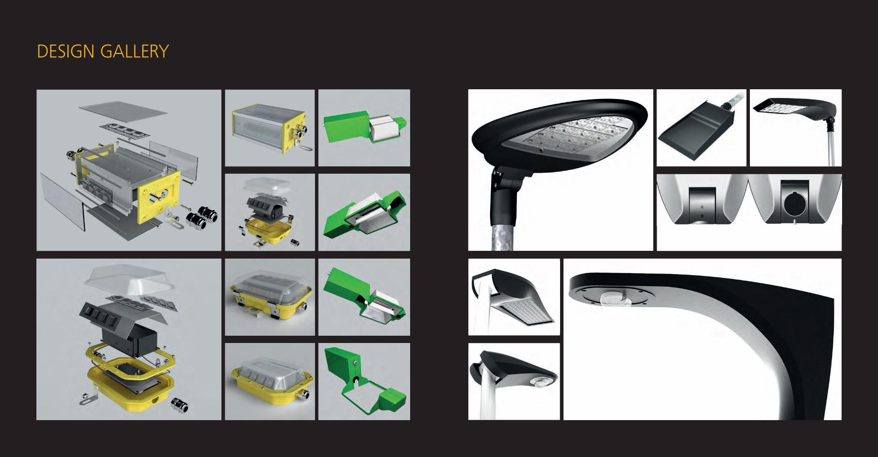
DESIGN GALLERY
OPTICAL SYSTEM DEVELOPMENT
REFLECTOR & PARABOLIC LOUVRE DESIGN
REFRACTOR & DIFFUSER DESIGN
LIGHTING DESIGN
LENS DEVELOPMENT & TOOLING
THERMOMECHANICAL SIMULATION
CFD ANALYSIS
THERMOGRAPHY
LED LUMINAIRE LIFETIME PREDICTION
HARDWARE DESIGN
FIRMWARE DESIGN
SOFTWARE DESIGN
LABWARE DESIGN
ELECTRONIC DESIGN CONSULTANCY
THE TUNABLE WHITE STORY
SHEET METAL DESIGN
ALUMINIUM DIE CAST & EXTRUSION DESIGN
ALUMINIUM FORGING
MECHANICAL ANALYSIS
INDUSTRIAL DESIGN THERMAL DESIGNOPTICAL DESIGN MECHANICAL ENGINEERINGELECTRONIC DESIGN

INDUSTRIAL DESIGN A good designer establishes a strong visual hierarchy. As Saint-Exupery said:
“A designer knows he has achieved perfection not when there is nothing left to
add, but when there is nothing left to take away.” Yes, to do a good design is
not only about what, but also why, and how. After all, design is not just making
things pretty; it’s also making them work well. iLumTech designers work with
all other departments to assure that the final product works, can be manufac-
tured, and will be successful and unique.
“I think it’s the responsibility of a designer to
try to break rules and barriers.” Gianni Versace

I 25 24 I INDUSTRIAL DESIGN / DESIGN RESEARCHPRODUCT DEVELOPMENT & ENGINEERING SERVICES
DESIGN RESEARCH
Every company wants extraordinary products. But how to create them? Based on a full understanding of your specific needs, we can precisely de-fine targets and provide fresh ideas that we then transform into viable and inimitable high-class industrial products.
DESIGN RESEARCH
CONCEPT & PRODUCT DESIGN
MOCK-UPS
PRODUCT & CORPORATE PROMOTION
WHY IS DESIGN RESEARCH IMPORTANT?• IT SUPPORTS THE CREATION OF UNIQUE PRODUCTS• YOU FULLY UNDERSTAND THE COMPETITION, AND SO CAN DO THINGS BETTER• YOU KNOW ALL THE TRENDS AND ARE READY FOR THE FUTURE• YOUR SALES SUCCESS IS GUARANTEED IN ADVANCE
STYLE DEFINITION To support your unique corporate identity through design, we assess your visual style and analyse how it will de-fine the creative process. This acts as the base for product definition, brand development, and portfolio expansion.
COMPETITOR RESEARCH By performing comprehensive mar-ket research, we can create an overview of current relevant competitor strategies for selected product groups. This under-pins every new product development by providing necessary context and contrast for product and market definition.
DESIGN STRATEGY For a product to be successful, it must find its niche in the market. The shapes, colours, and materials chosen should fol-low the desires of the target customer. To help you find out what your customer really wants, we will guide your product focus and marketing strategy, which will in turn support the setting of release dates. Our knowledge of the lighting industry and competition further helps us to understand the design require-ments of different customer groups and markets from a geographical and social point of view – advice we are happy to share with you.

I 27 26 I PRODUCT DEVELOPMENT & ENGINEERING SERVICES INDUSTRIAL DESIGN / CONCEPT & PRODUCT DESIGN
CONCEPT & PRODUCT DESIGN
Product design covers all the pre-production processes that lead to a fully functional prototype. By combining our creative cross-industry exper-tise with software analysis, CAD virtual reality simulation, and effective manufacturing processes, we can ensure lean production and the reliability and quality of the developed product.
DESIGN RESEARCH
CONCEPT & PRODUCT DESIGN
MOCK-UPS
PRODUCT & CORPORATE PROMOTION
WHY RELY ON OUR DESIGNERS?• WE KNOW THE LIGHTING MARKET• WE UNDERSTAND HOW TO CONNECT WISH WITH REALITY• WE WORK CLOSELY WITH OPTICAL, ELECTRONIC, AND MECHANICAL ENGINEERS• WE LISTEN AND AIM WHERE YOU ARE AIMING• WE ARE OPEN-MINDED
PROJECT DEFINITION We will select the aesthetic style and features of the product based on its ba-sic technical definition, market and cus-tomer profiling, and technological and user trends.
CONCEPT INNOVATION This is a process that includes mind mapping and critical discussion that al-lows us to combine and develop under-standing of product needs, creation of initial concepts, and selection of meth-ods for delivering satisfactory results. We approach every product design with an open mind and focus on crea-tive and uninhibited thinking.
PRODUCT DESIGN The next step is to go into more de-tail by assessing and selecting the best shapes, colours, materials, and textures in order to meet specific needs. This is the most critical step in the process and often includes provision of several proposals that can be evaluated against key indicators to more closely define the basic features of the final product. Through close cooperation with our mechanical engineers, we can keep our feet on the ground when prepar-ing design proposals, while also letting our “designer’s fantasy” take flight. The result is a truly unique, interesting and producible product.
DESIGN MANAGEMENT In close partnership with our product managers, we can support and evaluate your product strategy and set-up achiev-able and measurable goals that take your product all the way from concept to suc-cessful release to the market.
PRODUCT OPTIMISATION & ENHANCEMENT Thanks to connection with the me-chanical engineering department and our knowledge of manufacturing pro-cesses, we can support other companies with product optimisation and enhance-ment. Do you have manufacturing diffi-culties and need a design modified, or would you like to reduce costs? Whatev-er you need, we will find a way to satisfy.

I 29 28 I PRODUCT DEVELOPMENT & ENGINEERING SERVICES INDUSTRIAL DESIGN / MOCK-UPS
MOCK-UPS
Nothing can replace the experience of a physical product model. We can create mock-ups that simulate the physical appearance of a product, and those that simulate its functionality, using a wide range of methods from clay modelling and vacuum forming to hand-modelling techniques.
DESIGN RESEARCH
CONCEPT & PRODUCT DESIGN
MOCK-UPS
PRODUCT & CORPORATE PROMOTION
MOCK-UPS WITHIN UNBEATABLE TIMESCALES• CLAY MODELS• PAPER MOCK-UPS• STYROFOAM MOCK-UPS• FUNCTIONAL MOCK-UPS
PHYSICAL APPEARANCE MOCK-UPS Physical appearance mock-ups are suitable for shape and proportion as-sessment, material, surface texture, and colour evaluation, and to support com-ponent selection.
FUNCTIONAL MOCK-UPS Functional mock-ups are a working model of the product and do not ad-here to aesthetic design details. They are very useful throughout the entire product development process to guide the enhancement and optimisation of designs, especially during the early stag-es when fundamental decisions need to be made about basic parameters.
APPLICATION MOCK-UPS One of the best ways to promote your product is to show how it looks and works in a realistic setting. We can develop and construct application mock-ups at various scales, from mobile mod-els with integrated miniature products and simulated functionality to full-scale models of spaces with installed product prototypes.

I 31 30 I INDUSTRIAL DESIGN / PRODUCT & CORPORATE PROMOTIONPRODUCT DEVELOPMENT & ENGINEERING SERVICES
PRODUCT & CORPORATE PROMOTION
Many quality products do not make it to the market because they lack the right promotion. Let us support you by providing everything from interactive full-scale models suitable for location testing and photo shoots to animated presentations and even complete retail solutions. Our team will apply the full breadth of its experience to make your product visible on the market.
DESIGN RESEARCH
CONCEPT & PRODUCT DESIGN
MOCK-UPS
PRODUCT & CORPORATE PROMOTION
WHAT SUPPORTS PROMOTION?• A SUITABLE MARKETING STRATEGY• ORIGINAL PACKAGING• VISUALISATIONS AND PRESENTATIONS• MOBILE MODELS FOR SITUATION SIMULATION
MARKETING STRATEGIES Based on our market and competi-tor research, industry experience, and in-depth knowledge of your product, we will help you develop suitable targeted, local, and global marketing strategies for your product, and even for your brand.
PROMOTIONAL VISUALISATIONS & PRESENTATIONS Using specialised CAD rendering programmes and post-production tech-niques, we can create realistic product visualisations suitable for a range of uses. We can also develop presenta-tions in static, animated, 3D or video format according to your needs.
EXHIBITION STAND DESIGN CONSULTANCY Having significant experience in the development and construction of exhi-bition stands, we offer design consul-tancy to support the best presentation of brands and products at trade shows. Stand designs are tailored to the type of exhibition, purpose of your presence there, and will follow closely your brand and market image.
PACKAGING DESIGN Eyes buy. Packaging design is crucial to the sales success of every product. We can provide for you any packaging design you need, suitable for retail. To do this, we rely on specialised software that allows us to create a wide range of variants and possibilities. All you need to do is select which you think will most encourage your customers to buy.
VIRTUAL MODEL CONSTRUC-TION 3D virtual models are usually request-ed to aid in shape assessment, construc-tion evaluation, or as a way to measure several key indicators. Just let us know what format and quality you need, and we can prepare models that will help development move forward. Such mod-els may also be used for other purposes such as for inclusion in animations and presentations. Let your imagination go, and rely on us to make presentation of your business easier.

DESIGN GALLERY
OPEN THE DOOR TO A NEW WORLD OF LIGHT The most common function of the door is its ability to be locked. In order to know if the door is locked, we can use a subtle light that will switch on af-ter locking. The same function can also be used in the case of interior doors where privacy is needed, for example, on bathroom doors.
Another possibility is to use differenti-ating lighting effects on doors. In this case, the number or name of the room can be illuminated. The use of various colours, shapes, and lighting techniques will also support the aesthetic element of the door’s design. Thanks to this, the user can even reduce the number of other auxiliary devices such as emer-gency signs and room names.
Finally, each door needs to have a door handle. Why not also extend the pos-sibility of illumination to this element? We suggest that a door handle could be equipped with an ambient light sensor, allowing for a small light to be switched on automatically in low light levels so that people can easily find their way without needing to turn on a bigger light.
In addition to playing a functional role, doors also play an aesthetic role and should follow the style, architecture, and design of a building, room, vehicle or space. Therefore, we can say that doors have both a utilitarian and aesthetic element. Door manufacturers need to find ways to improve the fulfilment of both of these elements if they want to deliver to the market original and interesting solutions. One way to do make doors more attrac-tive to customers is to combine them with lighting.

DESIGN GALLERY
DESIGN GALLERY

OPTICAL DESIGN It is always possible to develop a product using commercially available optical
systems. However, if you really want to be a manufacturer of successful, unique,
and interesting luminaires while maintaining control over costs, there is only
one way to proceed that makes sense: to develop and produce tailored lens or
reflector systems. We have the skills and experience to support you throughout
the entire process, from design through to tooling and production.
“Music is the arithmetic of sounds as optics is
the geometry of light.” Claude Debussy

I 41 40 I OPTICAL DESIGN / OPTICAL SYSTEM DEVELOPMENTPRODUCT DEVELOPMENT & ENGINEERING SERVICES
OPTICAL SYSTEM DEVELOPMENT
Optimal luminaire performance is only achieved if effective and appropri-ate optical parts are selected and refined to meet the specific needs of each product. We have access to the latest development technologies as well as having vast practical experience and theoretical knowledge, all of which are applied to every product that passes through our hands.
OPTICAL SYSTEM DEVELOPMENT
REFLECTOR & PARABOLIC LOUVRE DESIGN
REFRACTOR & DIFFUSER DESIGN
LIGHTING DESIGNWHAT DOES OPTICAL DESIGN INCLUDE?• SELECTION OF THE RIGHT LIGHT DISTRIBUTION• EVALUATION OF THE MOST SUITABLE OPTICAL PARTS• COMBINING OF DIFFERENT OPTICAL SYSTEMS• CHECKING THE SUITABILITY OF COMMERCIALLY AVAILABLE PARTS• DESIGN OF TOTALLY NEW OPTIONS• TESTING AND OPTIMISATION OF PARTS• CLOSE PROFESSIONAL COOPERATION WITH ALL OTHER ENGINEERING DEPARTMENTS
OPTICAL PART SELECTION There are several types of optical part to choose from, each with its own strengths and each suitable for different uses. Reflectors and parabolic louvres change the light emitted from the light source by reflection and are made from materials with high reflectance, with parabolic louvres also serving to shield light sources from view at key angles. Refractors and lenses change the light distribution of a light source by refrac-tion and are made of materials with direct transmission. Diffusers change the light distribution mostly by diffu-sion and are made from materials with light diffusing properties. The choice of the most suitable optical parts for each product is the first step in the design of a tailored optical system.
SPECTRAL & LUMINANCE ANALYSIS When designing an optical system, it is vital to know what light param-eters are required and to ensure that the product under development meets those needs. This includes knowledge of the luminance, LIDC, Colour Rendering Index (CRI), and Correlated Colour Tem-perature (CCT) of the light source. We can perform the spectral and luminance analysis of light sources, which allows us to save both time and money by creat-ing and analysing mathematical models rather than needing to produce expen-sive working prototypes.
OPTICAL SYSTEM OPTIMISATION Based on in-depth spectral and lu-minance analysis, we can optimise any part of an optical system in accordance with international standards. Virtual pro-totyping, simulation, optimisation, and creation of photo-realistic renders of pre-cision illumination applications is done using LightTools®, one of the best-known software applications used for optical analysis. The software has adapted solid modelling technology to accommodate the inherent accuracy required to simu-late the ray paths of light as they traverse through and within optical elements and mechanical structures. In terms of optical design and analysis, it provides us with unlimited possibilities.

I 43 42 I OPTICAL DESIGN / REFLECTOR & PARABOLIC LOUVRE DESIGNPRODUCT DEVELOPMENT & ENGINEERING SERVICES
REFLECTOR & PARABOLIC LOUVRE DESIGN
There are many different types of reflector to use to help create a de-sired light distribution: conical, elliptical, zonal, hyperbolic, freeform, etc. The task of the optical designer is to select the most suitable option and optimise it to meet your specific requirements.
OPTICAL SYSTEM DEVELOPMENT
REFLECTOR & PARABOLIC LOUVRE DESIGN
REFRACTOR & DIFFUSER DESIGN
LIGHTING DESIGN
BASIC INPUTS NEEDED FOR REFLECTOR DESIGN• APPLICATION, AMBIENT CONDITIONS, AND STANDARD INSTALLATION PARAMETERS• 3D STP FILE OF THE LUMINAIRE• DIMENSION LIMITATIONS• TYPE OF LED TO BE USED• REQUIRED LIGHTING PARAMETERS• REQUESTED LIDC• DESIRED EFFICIENCY AND UGR VALUE• PRODUCTION TECHNOLOGIES TO BE USED• SPECIFIC MATERIAL AND SURFACE FINISH PROPERTIES
REFLECTOR SELECTION Selecting the most suitable reflec-tor depends on the type of luminaire it will applied to and where that luminaire will be used. For example, spotlights are generally equipped with faceted coni-cal reflectors whereas linear luminaires used in industrial settings tend to be equipped with a simple reflector with a metallic or white surface finish. We have an extensive library of materials from which to choose to make sure that the reflector used will perform as needed.
REFLECTOR OPTIMISATION In order to provide the exact LIDC needed, we will check with you about various details of the space the lumi-naire will be used in. We will also ask you if there are any specific lighting parameters that must be provided. The answers allow us to define optical pa-rameters and modify the reflector ac-cordingly. For this purpose, we have de-veloped our own LIDC Optimiser tool, which is used together with LightTools®.
REFLECTOR DESIGN Reflective optics use reflection to capture the light emitted by a light source, in most cases in the form of parabolic, hyperbolic or elliptical reflectors. It is most difficult to create freeform reflectors, which are able to precisely deliver light to the right place and with the right intensity. This will be a key point in our future reflec-tor designs: that there be no limitation to the optical design of reflective optical parts. We work closely with the mechani-cal engineers at this stage as they create the mechanical design of the reflectors in CATIA, which in turn acts as the base for tooling and production. It is therefore very important for us to know if you have any technology specifications regarding the production of the reflector, as this will influence material selection and possibly even the shape of the reflector.
OPTICAL RESEARCH We have developed a 60° reflector suitable for spot luminaires, which is avail-able from our portfolio.

I 45 44 I OPTICAL DESIGN / REFRACTOR & DIFFUSER DESIGNPRODUCT DEVELOPMENT & ENGINEERING SERVICES
REFRACTOR & DIFFUSER DESIGN
If you want a uniform light distribution with a specific LIDC, the most suitable optical system for you will be one based on refraction, which is the modification of a light ray’s movement through a material. There are two types of refractive optical part: refractors and diffusers. The choice of the best option for your needs is the job of experienced lighting designers.
OPTICAL SYSTEM DEVELOPMENT
REFLECTOR & PARABOLIC LOUVRE DESIGN
REFRACTOR & DIFFUSER DESIGN
LIGHTING DESIGNWHEN IS A REFRACTOR OR DIFFUSER THE BEST CHOICE?• YOU NEED HOMOGENOUS AND UNIFORM ILLUMINATION• THERE ARE LOW UGR REQUIREMENTS• TO COVER LEDS• YOU WANT SOFT, DIFFUSED LIGHT
REFRACTOR & DIFFUSER SELECTION The most commonly used refractive materials are in fact referred to as diffus-ers as their refractive properties cause diffusion of the transmitted light. There are also diffusers that do not use refrac-tion but are rather made of materials with light diffusing properties. It is dif-ficult to understand the advantages and disadvantages of each type of refrac-tive or non-refractive diffuser, especially in terms of its application in a specific setting. We are experienced in making these choices and can help you under-stand which best suits your needs.
REFRACTOR OPTIMISATION It is possible to modify a refractive material in order to achieve a desired LIDC; however, this is an incredibly dif-ficult task that requires a high level of ex-pertise. To help us with this process, we have developed our own LIDC Optimiser software, which helps us determine the precise LIDC needed for each applica-tion, and provides calculations we can use as a base for optical optimisation.
REFRACTOR DESIGN There are a variety of refractive op-tics used in illumination systems. In this group, we can find lenses, arrays, prisms, pillow optics and also protective covers. Based on this great flexibility, we are able to create any refractor design according to customer needs.
OPTICAL RESEARCH In addition to the design and optimisa-tion of optical systems and parts, we also put a great deal of energy into optical re-search. We have developed a nano-diffus-er that can be used as a replacement for standard optical parts such as prismatic diffusers, louvres, and reflectors. Our na-no-diffuser is a thin PMMA plate applied with opto-mechanical nano-structures that control light distribution by modify-ing the surface or volume of the material. The optical relief in invisible as the dimen-sions of the structures is in nanometres (microns). The bitmap design consists of million of pixels that represent structures (Fresnel lenses) that can focus, collimate, partially collimate, and diverge incoming light beams in the same way as conven-tional lenses, but, thanks to the size, allow for more precise control of the light and so greater optical efficiency. By placing the nano-diffuser at different distances from the LEDs, the LIDC can be modified. Our nano-diffusers are available from the iLumTech portfolio.

I 47 46 I OPTICAL DESIGN / LIGHTING DESIGNPRODUCT DEVELOPMENT & ENGINEERING SERVICES
LIGHTING DESIGN
Lighting design services form an integral part of each product develop-ment process as it helps us to ensure that it will fit the designated applica-tion. It is a standard part of optical development and performance assess-ment to test a luminaire in an appropriate practical-use simulation. As a result, we have great experience in checking how products suit the require-ments of an application, and in proposal of suitable solutions – services we extend to you also.
OPTICAL SYSTEM DEVELOPMENT
REFLECTOR & PARABOLIC LOUVRE DESIGN
REFRACTOR & DIFFUSER DESIGN
LIGHTING DESIGNLIGHTING DESIGN OUTPUTS• LIGHTING CALCULATIONS• ENERGY SAVING CALCULATIONS• 3D VISUALISATIONS• CAD PRODUCTION
LIGHTING DESIGN Our optical designers have in-depth understanding of lighting project re-quirements and can help you achieve the correct illumi nation – whether it is inspirational lighting effects for your ho-tel, house or garden, or assured visual acuity throughout a town and its streets. We use DIALux in combination with a range of proprietary tools to make sure you get the most suitable lighting pos-sible. Outputs include 3D visualisations, lighting calculations, energy saving cal-culations, and CAD production.

LENS DEVELOPMENT & TOOLING
OPTICAL DESIGN A simple lens is made from a trans-parent material that transmits and re-fracts light and converges or diverges the beam. Lenses allow us to achieve lighting parameters other optical sys-tems can’t. For this reason, multi-lenses are often used in modern LED street luminaires where norms stipulate very strict illumination requirements. We have experience in developing lenses according to request.
MECHANICAL DESIGN Once an optical design is finalised, we will prepare the mechanical design within which the optics will be placed. This is usually done on the basis of a customer PCB and luminaire, whether real or to be developed. The mechanical design also includes the design of requested pack-aging. Next, we create a prototype that enables us to assess the suitability of the design for tool production, and the me-chanical fit of the lenses within the lu-minaire in preparation for IP testing and rating. We use various proven external partners with specialist experience in this field for the creation of such prototypes. All prototypes are evaluated by us based on precise photometric measurements.
LENS OPTIMISATION Lenses are commonly positioned directly on the LED, and come in many shapes and sizes. Only experienced and knowledgeable optical engineers know how to determine the best lens for each product. For highly demanding street lighting luminaires, we have developed our own Street Light Configurator, which allows us to combine up to four different lenses at various angles to pro-vide a desired LIDC.
TOOL PRODUCTION The third step is the preparation of production tools. The creation of die cast moulds can take several weeks, and for this we cooperate with top-class manu-facturers from the automotive industry. We will take care of this entire process by visiting manufacturers, organising the output quality and, if needed, arranging for tool corrections. We check the per-formance of all tools before approving them and sending them to the produc-tion location. The customer is also pro-vided with a certificate of ownership.
LENS MANUFACTURE We can go on to organise the full production of optical parts on request, including tool setup and calibration. Thanks to collaboration with external manufacturers located close to our site, we can provide smooth and efficient lo-gistics and communication hand in hand with stress-free service at unbeatable prices.
Lenses have become a standard part in optical design, especially in LED luminaires. They offer incredible flexibility of design and application as well as improved mechanical and optical parameters compared to conventional optical technologies.

THERMAL DESIGN The most important part of thermal design is thermal simulation, without
which many thermal solutions fail to deliver a required performance for an ap-
plication. By using SOLIDWORKS (module FloEFD R20), we are able to verify and
compare thermal designs, optimise them for given luminaires, and so ensure
that your thermal design will work.
Whether you have come to us for full luminaire development or wish to increase
the performances of a current product, we are at hand and ready to share our
testing and simulation experience.
“Nothing in life is certain except death, taxes,
and the second law of thermodynamics.” Seth Lloyd

I 53 52 I THERMAL DESIGN / THERMOMECHANICAL SIMULATIONPRODUCT DEVELOPMENT & ENGINEERING SERVICES
THERMOMECHANICAL SIMULATION
Many materials experience changes in their thermomechanical properties during heating and cooling. Changes that affect the reliability of products. Thermomechanical simulation allows engineers to understand how the struc-ture of a device behaves under both thermal and mechanical loading, ena-bling the prediction of structural reliability. We evaluate each design from a thermal point of view, whether that be of a full luminaire or of just electronic, optical or mechanical designs and parts. We can offer assured results thanks to necessary close partnership with all other engineering departments.
THERMOMECHANICAL SIMULATION
CFD ANALYSIS
THERMOGRAPHY
THERMAL SIMULATION MAKES SENSE• SELECT THE MOST SUITABLE MATERIALS AND TECHNOLOGIES• ENABLES OPTIMISATION OF A PRODUCT’S WEIGHT• SUPPORTS THE BEST POSITION OF COMPONENTS WITHIN A PRODUCT• POSITIVE INFLUENCE ON ENVIRONMENTAL FACTORS• ALLOWS FOR OPTIMISATION OF HEATSINKS ACCORDING TO CONDITIONS TO MINIMISE COSTS• UNDERPINS APPROPRIATE COMPONENT SELECTION
SOLUTION OPTIMISATION Advanced computer simulations al-low us to analyse and understand the performance of structures and systems so that we can improve them. This re-quires the cooperation of engineers and designers throughout product develop-ment with the aim of providing useful and constructive feedback and ideas. Thermal simulation is performed using SOLIDWORKS equipped with a wide range of additional modules.
LIFETIME PREDICTION The basic steps involved in thermo-mechanical lifetime assessment are fluid dynamics studies, transient thermal cal-culations, and mechanical computations that identify loading conditions. Lifetime estimation for thermally and mechanical-ly loaded products is both time-consum-ing and expensive. Therefore, fatigue simulation is a vital part of the develop-ment process as it minimises timescales and costs.

I 55 54 I THERMAL DESIGN / CFD ANALYSISPRODUCT DEVELOPMENT & ENGINEERING SERVICES
CFD ANALYSIS
Our thermal engineers are able to evaluate not only the influence of heat on a product, but also the influence of fluids (gases or liquids). In the case of luminaires, this can be with regard to the influence of wind or air condition-ing. Such analysis helps to predict what force constitute a dangerous situa-tion, and how the product will behave under these conditions.
THERMOMECHANICAL SIMULATION
CFD ANALYSIS
THERMOGRAPHY
WHY CFD ANALYSIS?• TO DESIGN A PRODUCT FASTER AND MORE RELIABLY• TO ASSESS PERFORMANCE AND EFFECTIVENESS BEFORE COMMITMENT TO TOOLING• TO OPTIMISE LUMINAIRE PERFORMANCE• TO EVALUATE PRODUCT WEIGHT AND HEATSINK TYPE• TO HELP BALANCE OVERALL PERFORMANCE WITH DESIGN AND PRICE• TO EVALUATE MANUFACTURING POSSIBILITIES• MAIN APPLICATIONS INCLUDE OUTDOOR, INDUSTRIAL, TRAFFIC, SIGNAL, AND AUTOMOTIVE LUMINAIRES
FORCE PREDICTION To minimise and control the risk of dangerous conditions from exceptional air velocities, forces, pressures, and ac-celerations, it is important to assess and understand the effects of such forces on all components and the assembly of a product. Strong winds such as those experienced during heavy storms and hurricanes induce forces and pressured distributions on objects that can lead to safety issues and potentially dangerous conditions. To avoid disaster, force pre-dictions for a product need to be incor-porated into its design from a very early stage.
FLUID DYNAMICS The analysis of a fluid (gas or liquid) within a device is very complex as it is based on heat transfer, mixing, and un-steady and compressible flows. To predict the impact of fluid flow on a product can be both time consuming and very costly without appropriate simulation tools. Computational Fluid Dynamics (CFD) analysis enables the quick and ef-ficient simulation of both fluid flow and heat transfer in order to calculate fluid forces and understand the impact of a gas or liquid on product performance. By performing robustness predictions for an untested idea, fluid dynamics helps us to place true design innovation within reach.

I 57 56 I THERMAL DESIGN /THERMOGRAPHYPRODUCT DEVELOPMENT & ENGINEERING SERVICES
THERMOGRAPHY
Radiation is one of the heat transfer mechanisms in which electromag-netic radiation is emitted by a heated surface. Heat transferred by radiation does not depend on contact and can be transmitted through empty space. Examples of radiation are heat from the sun or the heat emitted by the fila-ment of a light bulb. Advantages of using thermography include its ability to capture real-time temperature states, produce a picture of temperature over a large area, and measure inaccessible areas, as well as the fact that it is a non-destructive procedure.
THERMOMECHANICAL SIMULATION
CFD ANALYSIS
THERMOGRAPHY
WHEN WE USE THERMOGRAPHY• TO IDENTIFY THERMAL DESIGN ISSUES BY CAPTURING REAL-TIME TEMPERATURE STATES• FOR VIEWING OF TEMPERATURE PARAMETERS OVER A LARGE AREA• FOR MEASUREMENTS OF INACCESSIBLE AREAS• IN CASES WHERE CONTACTLESS MEASUREMENT IS REQUIRED
REAL-TIME CAPTURE OF INFRARED IMAGES Thermography enables us to meas-ure temperatures in applications where conventional sensors can’t be used. This is especially the case when dealing with the measurement of moving objects or where contactless measurement is re-quired due to the risk of contamination or hazardous occurrences.

LED LUMINAIRE LIFETIME PREDICTION
LM80 TEST The LM80 test is a Department of Energy (DOE) approved method for measuring lumen depreciation of solid-state (LED) light sources, arrays, and modules. The Illumination Engineering Society (IES) and DOE Solid State Lighting Standards Development group worked together to create the LM80 test criteria.
TM21 TEST In August 2011, IES published a TM21 document entitled “Lumen degra-dation estimation method for LED light sources.” TM21 is the IES-recommended method for projecting the lumen deg-radation of an LED package, array, or module, based on data collected accord-ing to LM80.
The lighting community expects TM21 to become the standard method for pro-jecting useful LED lighting product life at realistic operating temperatures.
It is sometimes very difficult to work out the truth about a luminaire’s lifetime, so a simple explanation is in order. What exactly does LM80/TM21 mean in relation to a luminaire’s lifetime? The short answer is… not a lot!
LM80 and TM21 refer only to the predicted lifetime of LEDs and COBs. How the LEDs are mounted, cooled, and driven are the key factors affecting luminaire lifetime. What LM80 and TM21 data does do, however, is provide luminaire manufacturers with a way to directly compare LEDs or COBs to allow them to make the best choice of component to achieve a good luminaire lifetime.
WHAT DOES IT MEAN IN SIMPLE TERMS?IES LM80-80-2008 “Measuring Lumen Maintenance of LED Light Sources” is the industry stand-ard method for testing LEDs to determine lumen depreciation over time. It is carried out over a 6000 to 10,000 hour period, with luminous flux measured at 1000 hour intervals. As a typical example, let’s say the depreciation is 3 %. That means a 97 % maintenance of light output. And further, perhaps after 10,000, there is a depreciation of 6 % or 94 % maintenance.
Historically that was it, and LED manu-facturers could draw their own curve through the test points and boldly quote a 50,000 hour lumen maintenance of 70 % (L70) output while others would go as far as to quote 90 % (L90). Basically, before TM21 came along, there was no agreed standard as to how to predict the end of useful life. This was not helpful for us as luminaire manufacturers, or you as customers.
IES TM21-2011 “Projecting Long Term Lumen Maintenance of LED Light Sources” recommends a method how to use the LM80 data to predict the lumen main-tenance of an LED. Simply put, an expo-nential curve is drawn between the 1000 hour test points on a graph plotting lumen maintenance from 70 % against a timeline of up to 100,000 hours. This could well give a calculated figure of L70 = 50,000 hours.
However, it is also stipulated in TM21 that the maximum life that may be quoted is six times the actual test dura-tion. So, if the test duration is only 6000 hours, the maximum life that can be quoted is 36,000 hours and would be quoted as L70 (6K) >36,000 hours. If 10,000 hours of testing were carried out, it would be quoted as L70 (10K) >60,000 hours.
It’s obviously more complicated than this and the tests are actually carried out at 3 different LED case temperatures; 55 ºC, 85 ºC, and a manufacturer selected tem-perature. (The meaningful one is 85ºC as this represents practical conditions).
Don’t forget, this is just telling us about the performance of an LED in lab condi-tions with controlled cooling and drive current, and doesn’t take account of ambient temperatures or power supply. Beware, therefore, what is quoted as a luminaire lifetime. We’ve seen lifetimes of >100,000 hours L90 at 25 ºC quoted in big letters on luminaire datasheets, and in small print, “this is with a junc-tion temperature of Tj = xx and is the LED manufacturers data”. It looks good, but is rather misleading.
LM80 DEGREDATION CURVE OF AN LED LIGHT SOURCE
TM21 DEGREDATION CURVE OF AN LED LIGHT SOURCE
Hours
Hours
Lumen maintenance 3000 Kat 0.7 A, 55 ºC (Tj = 74 ºC), 85 ºC (Tj = 103 ºC), 105 ºC (Tj = 123 ºC)
Normalised to 1 at 0 hours
Exponetial curve is fit to the data points between
1000 and 6000 hours
1000
1000
0.6
70
0.7
75
0.8
80
0.9
85
95
1.0
90
105
1.1
100
110
10,000
10,000
100,000
100,000
Nor
mal
ised
ligh
t ou
tput
Nor
mal
ised
ligh
t ou
tput
105 ºC85 ºC55 ºC105 ºC TM2185 ºC TM2155 ºC TM21EPA limitsTM21 limitsBeyond L70 (6 K) >36,000

ELECTRONIC DESIGN
Whether you need to develop new hardware, a PCB, or need support in
software development, we will help you reach the finishing line. We have the
expertise and experience to design hardware and software to meet your exact
needs, and can take a project from concept through production under one roof.
“It’s hardware that makes a machine fast.
It’s software that makes a fast machine slow.” Craig Bruce

I 63 62 I ELECTRONIC DESIGN / HARDWARE DESIGNPRODUCT DEVELOPMENT & ENGINEERING SERVICES
HARDWARE DESIGN
Since hardware is the basis of each electronic device, there is vital need for good hardware design to ensure the quality, reliability, and long-term stability of a solution. Our hardware design engineers are responsible for the complete development process from idea to final product.
HARDWARE DESIGN
FIRMWARE DESIGN
SOFTWARE DESIGN
LABWARE DESIGN
ELECTRONIC DESIGNCONSULTANCY
HARDWARE DESIGN INCLUDES• KEY COMPONENT SELECTION WITH COST EVALUATION• ELECTRONIC/PCB SCHEMATIC DESIGN• FUNCTIONAL PROTOTYPING• TEST REPORTS AND COMPLETE DOCUMENTATION• POSSIBILITY TO CONTINUE WITH MANUFACTURE ON REQUEST• USE OF THE DALI LOGO IF APPLICABLE
KEY COMPONENT SELECTION The overall cost and complexity of a device depends mainly on key compo-nent selection. The ratio between those parts needed for the hardware, firmware, and software of the product are put in place during this phase of development.
SCHEMATIC DESIGN The functional schematic of a so-lution is based on chosen key com-ponents, supporting blocks, and the analysis of customer needs. Schematic sdefine the complexity and final cost of a developed solution.
PCB DESIGN PCBs are designed based on a func-tional schematic with consideration also given to mechanical factors. The design is strongly influenced by forecasted pro-duction quantities, based upon which appropriate PCB manufacturing tech-nologies are selected. Electrical safety requirements also have an impact on the design rule check.
PROTOTYPE A prototype is an integral part of the development process as it is the first real substantiation of your vision. It also acts as the base for demonstration of func-tionality and subsequent corrections and price adjustment of the product. Several prototypes can be prepared dur-ing development.
DOCUMENTATION & VALIDA-TION One of the primary outcomes of the development process is the technical documentation of the product. This ena-bles customers to run serial production as well as being a requirement for prod-uct certification.
FINAL PRODUCT Finalisation of the development pro-cess is marked by the product entering serial production. This is based on the aforementioned technical documenta-tion and requires that the product first receive appropriate certification. We also offer you the possibility to continue with the manufacture of your device or prod-uct at an attractive price level.

I 65 64 I PRODUCT DEVELOPMENT & ENGINEERING SERVICES ELECTRONIC DESIGN / FIRMWARE DESIGN
FIRMWARE DESIGN
Firmware, or programmable components, are are used in almost every electronic product found on today’s market. We have been dealing with firm-ware design for several years, mainly in the field of 8- and 32-bit core ST Mi-croelectronics architecture. However, we can also work with manufacturers such as Microchip, Atmel, NXP, or any other. This experience, in combination with use of advanced software tools STVD, Eclipse, and Keil MDK, mean that we can provide high-level firmware design on request.
HARDWARE DESIGN
FIRMWARE DESIGN
SOFTWARE DESIGN
LABWARE DESIGN
ELECTRONIC DESIGNCONSULTANCY
WHY FIRMWARE FROM US?• WE HAVE AT OUR DISPOSAL A VAST LIBRARY OF READY-TO-USE SOLUTIONS• WE PROVIDE COMPLIMENTARY HARDWARE AND SOFTWARE DESIGN• WE HAVE DIRECT ACCESS TO THE LATEST TECHNOLOGIES• WE PROVIDE FIRMWARE UPDATES
FIRMWARE SOLUTION ANALYSIS Analysis of a firmware solution is fundamental to the final electronic de-sign and results in the estimation of hardware requirements, MCU selection and a flow chart. We will need you to provide a list of features you expect the firmware to incorporate, based upon which we will decide if it is suitable to use an MCU. If so, we will provide an analysis of the solution including an es-timated memory size and details of any peripheral units that may be needed as well as the size of the required MCU and its selection. The final step is to prepare the firmware flow chart.
COMPLETE FIRMWARE DESIGN FOR PROTOTYPE DEVICE The next phase is to design the firm-ware itself. We select ready-to-use func-tional blocks or create completely new ones and then define the relationships between them. The outcome is functional firmware tested on a real prototype. Ac-companying full documentation includes source code, any necessary software tools, and a comprehensive description of the design.
SUPPORT & MAINTENANCE OF FIRMWARE FOR MANUFACTURE There is a world of difference be-tween firmware designed for a pro-totype device and that needed for se-rial manufacture. For manufacture, it is necessary to take into consideration the workflow needed for the programming of devices. We can provide device pro-gramming within our own facilities or prepare for you a programming tool to use in your own facilities. It is common during the first months that some ‘bugs’ will appear, and you may also have ideas about how to improve the product. For this reason, we are also happy to correct and update firmware.

I 67 66 I ELECTRONIC DESIGN / SOFTWARE DESIGNPRODUCT DEVELOPMENT & ENGINEERING SERVICES
SOFTWARE DESIGN
There are hundreds of thousands of software programs on the market that can do almost anything you could desire, yet, these programs are so diversified and specified that it is nearly impossible to find one that does everything you need in one package. This necessitates the creation of some-thing precisely tailored to your needs, which we can provide by combining our vast experience with use of the most appropriate development tools: LabVIEW, MS Visual Studio, and Android Studio.
HARDWARE DESIGN
FIRMWARE DESIGN
SOFTWARE DESIGN
LABWARE DESIGN
ELECTRONIC DESIGNCONSULTANCY
SOFTWARE THAT BRINGS ADDED VALUE• WE PROVIDE EXPERIENCE IN DELIVERY OF COMPLEX PROJECTS• WE HAVE THE CAPABILITY TO DEVELOP TAILORED SOFTWARE WITHIN SHORT TIMESCALES• OUR PROCESSES COMPLY WITH ISO 9001:2008• WE OFFER FUTURE SOFTWARE UPDATES
SOFTWARE DEVELOPMENT Our extensive and wide-ranging ex-perience in the design of all types of software for any PC or portable device platform is one of the reasons why you can rely on us. All software is developed in close cooperation with hardware and firmware to provide results characterised by their usability, portability, maintaina-bility, reliability, and security. Using smart programming approaches, we are able to develop qualitative software solutions within very short timeframes. We apply proven design patterns to ensure best practice and rapid development, and can provide updates thanks to use of Unified Modelling Language (UML) to combine techniques from data, object, and com-ponent modelling, which makes it easier and faster to implement future modifica-tions thanks to refactoring.
CUSTOMISED SOLUTION Software brings added value to a product when it precisely meets customer needs, and can, if appropriate, be con-trolled and set-up remotely. We can also update, optimise, or customise existing software with open protocols according to your needs, such as the software used in our own Connected Lighting range of products.

I 69 68 I ELECTRONIC DESIGN / LABWARE DESIGNPRODUCT DEVELOPMENT & ENGINEERING SERVICES
LABWARE DESIGN
Labware is a specific kind of software that automates operations in laboratories or in industry applications, controls machines and measuring instruments, and acquires data and process it. Our solutions are based on the LabVIEW development environment, which enables short develop-ment cycles, user-friendly GUI design, and a large number of libraries for data acquisition, data processing, data generation, mathematical analy-sis, statistics creation, etc. The extent of the features available allows us to offer complete turnkey solutions for fully-automated customer-defined measurement and processing units.
HARDWARE DESIGN
FIRMWARE DESIGN
SOFTWARE DESIGN
LABWARE DESIGN
ELECTRONIC DESIGN CONSULTANCY
LABWARE DESIGN INCLUDES• DATA ACQUISITION SYSTEM DESIGN• DESIGN OF AUTOMATIC MEASURING SYSTEMS• DEVELOPMENT OF INSTRUMENT CONTROLS AND DEVICE DRIVERS• DATA PROCESSING, MATHEMATICAL ANALYSIS AND STORAGE TOOLS• MACHINE CONTROL AND VISION DESIGN• COMPLETE TAILORED SOLUTIONS
DATA ACQUISITION SYSTEMS Data acquisition systems are respon-sible for measuring and sampling elec-trical or physical quantities and their subsequent processing. A complete data acquisition system is composed of sensors, measurement hardware, and a computer with programmable software. Such solutions are powerful, flexible, and cost-effective.
AUTOMATIC MEASURING SYS-TEMS Automatic measuring systems are useful when large numbers of electrical or physical quantities need to measured, necessitating the use of many different data acquisition devices. It is possible to synchronise the functions of all devices using a programming environment. The basic steps involved in this synchronisa-tion are the setting of hardware param-eters, acquisition of data, evaluation of that data, and the creation of reports. INSTRUMENT CONTROL & DEVICE DRIVER DEVELOPMENT Device drivers act as the software interface with the hardware device and should contain all the implemented func-tions. The main purpose of the driver is to create a higher-level application without requiring users to have detailed knowledge of the device hardware.
DATA PROCESSING, MATHEMATICAL ANALYSIS & STORAGE Data acquisition is the term used for the process of manipulating data in vari-ous ways in order to obtain meaningful results. These manipulations include mathematical calculations, signal pro-cessing, and report generation.
MACHINE CONTROL & VISION Machine vision is a technology used for automated inspection of and within industrial processes to achieve higher product quality. Other uses include the control of production processes and in-dustrial robots. Machine control and vision ensures high industrial process throughput and reduced production costs. A complete turnkey solution for a customer-defined measurement and pro-cess unit can be realised in one project. Each project includes hardware, firmware programming of the designed hardware, development of a device driver to act as the interface between the hardware and a higher-level application, and develop-ment of the control application.

I 71 70 I ELECTRONIC DESIGN / ELECTRONIC DESIGN CONSULTANCYPRODUCT DEVELOPMENT & ENGINEERING SERVICES
ELECTRONIC DESIGN CONSULTANCY
The performance of an electrical device is influenced by many factors. There are some basic principles that you can learn, but the real master of electronic design firstly needs to be experience. We can help you build high-performance and reliable systems and create custom designs using our expe-rience and knowledge. Support includes the provision of reference designs, detailed device and system design rules, design reviews, and general advice.
HARDWARE DESIGN
FIRMWARE DESIGN
SOFTWARE DESIGN
LABWARE DESIGN
ELECTRONIC DESIGN CONSULTANCY
HAVE A PROBLEM YOU NEED HELP WITH?• WE CAN IDENTIFY YOUR PROBLEMS• WE PREPARE EVALUATIONS OF PROPOSALS WITHIN SHORT TIMESCALES• WE PROVIDE CONSULTANCY AND ADVICE• WE OFFER TRAINING• WE CAN ORGANISE FUNCTIONALITY TESTS
ELECTRONIC DESIGN REVIEW Inspection of electronic designs during the development process can uncover potential weak points and risk areas, which should be treated care-fully by a responsible and experienced developer. During the electronic design review, we offer our extensive knowl-edge and expertise to help designers avoid problematic or clumsy solutions and so shorten the development pro-cess. Based on the advice we offer dur-ing consultation, electronic develop-ment can proceed in an optimal way thanks to the use of already proven and tested design blocks.
PROJECT SUPPORT Our skilled electronic engineers can also support you in the selection of de-vices suitable for your project, including any from our own Connected Light-ing portfolio. According to information about the project, such as usage, appli-cation, budget, and luminaire type, we can recommend the best type of Light-ing Management System (LMS) as well as offer LMS consultancy.
LIGHTING MANAGEMENT SYSTEM CONSULTANCY Good lighting does not stop at se-lection or development of the right lu-minaires, it also includes their intelligent regulation. For this, you will need a suita-ble LMS. And what constitutes a suitable LMS? Only that which understands and reacts to the real needs of users, offers the functions actually needed and does not waste money with those that are not, and which is easy to use. Our expe-rience of LMS devices and design, along with use of our own Connected Light-ing portfolio, allows us to make your life easier with tailored LMS designs.

THE TUNABLE WHITE STORY
MAKE THE RIGHT CHOICE Standard Tunable White technologies rely on the use of two independent power sources, one each for the warm and cold LED modules of the luminaire, necessi-tating the use of complex dimming and CCT control and additional regulation to avoid over-illumination caused by full powering of both modules. This results in the inclusion of more components, leading to lower product and operational reliability. Furthermore, the efficiency of the luminaires is affected by the CCT set, with optimal efficiency only achieved at the warmest and coolest CCTs.
iLumTech’s Tunable White is different – truly tunable. Brought to the market in the Connected Lighting family, it is based on a totally different principle, somewhat like that of a two-way valve. An electronic switch is used to regulate the direction of a single current flow to both warm and cold LED modules, meaning that only one power supply is needed and over-illumination impossi-ble. This leads to higher reliability thanks to simpler dimming and CCT control. What’s more, the luminaire’s efficiency is stable across all CCTs. iLumTech Tunable White modules come with a range of regulation methods including manual push button control, DALI control, and advanced user-interface control.
A NEW PERSPECTIVE ON TUNABLE WHITE It is well known that the func-tion of Tunable White luminaires is to provide illumination with various CCTs as required. The ability of Tunable White in combination with dimming to facili-tate human centric lighting is especially beneficial in areas where people need to maintain concentration for extended periods of time or to relax and perform according to a preset schedule. Such areas include offices, classrooms, kin-dergartens, and hospitals. However, optimal illuminance and CCT param-eters can easily be unbalanced by light coming from other sources, for example that from other luminaires or daylight from outside. Is there a way to main-tain desired illuminance and CCT values despite outside influences?
Luckily, we have developed the solution. The iLumTech DALI Ambient Sensor is the first of its kind on the market – able to measure both the illuminance (lux) and CCT (Kelvins) of ambient lighting parameters according to a spectrum weighted by tri-stimulus values X, Y and Z. The sensor can be used to adjust illu-minance and CCT values at a task area to maintain desired values in either a passive capacity by informing another control device on the same DALI bus, or in an active capacity as a combined sensor and control unit.
The Connected Lighting family contains two different types of Tunable White module: DALI type 6 and type 8. DALI type 6 modules require the use of two DALI addresses, one for brightness control and one for CCT control. DALI TW type 8 modules have the same func-tionality but do not require the use of an additional address as brightness and CCT can be regulated together using special commands.
The story of Tunable White does not end with LED modules and luminaires. Users also need to control them and take full advantage of their functionality through DALI. We consider it important that customers fully understand the differ-ences between standard and advanced control, and so can identify the most suitable for each application.
The DALI Ambient Sensor is capable of controlling various types of Tunable White luminaire: standard ones with inde-pendent cold and warm regulation and requiring two DALI addresses, DALI type 6 ones with independent CCT and illumi-nance regulation and requiring two DALI addresses, and DALI TW type 8 ones with combined CCT and illuminance regula-tion and requiring a single DALI address. Regulation is facilitated through grouping of luminaires according to their type, up to a maximum of five groups. This allows for luminaires of all types to be controlled simultaneously using group addresses for cold, warm, illuminance, CCT and DALI TW type 8 channels. Once the sensor is properly configured for active opera-tion, it can function as a stand-alone master controller on a DALI bus without the need for any other control unit. It is, however, possible to add extra control devices if desired.
The DALI Ambient Sensor is suitable for ceiling installation and should be con-nected to a DALI bus. Desired illumi-nance and CCT values can be defined using the iLumTech DALI to USB Bridge. The used protocol is currently of a pro-prietary nature but will be mapped to the updated DALI standard upon its completion, expected in 2016/17.
It is several years since the lighting industry began to consider dimming and the use of DALI as standard. Now, the same process is taking place regarding Tunable White as customers accept and even expect use of the technology in solutions. Despite this broad acceptance, the functional prin-ciples of Tunable White are still not widely understood: what are the differ-ences between Tunable White technologies, how are the devices controlled, what possibilities are available, and how can a desired CCT be maintained.

MECHANICAL ENGINEERING The experience and skill of our engineers combined with the power and
flexibility of the latest 3D CAD software from CATIA allows us to design and
customise whole products or their individual parts. Our precise document man-
agement system assures that you will receive all proper documentation from
which you can work in future. All data is available in 2D and 3D in various file
formats: STP, IGES, DXF and DWG.
“An optimist will tell you the glass is half-full; the
pessimist, half-empty; and the engineer will tell
you the glass is twice the size it needs to be.” Anonymous

I 77 76 I MECHANICAL ENGINEERING / SHEET METAL DESIGNPRODUCT DEVELOPMENT & ENGINEERING SERVICES
SHEET METAL DESIGN
Sheet metal is a very common material used in the construction of manyproducts, from cars to aeroplanes. We know all there is to know about shap-ing, forming, and combining sheet metal with other materials.
SHEET METAL DESIGN
ALUMINIUM DIE CAST & EXTRUSION DESIGN
ALUMINIUM FORGING
MECHANICAL ANALYSIS
WHAT YOU WILL RECEIVE• ITEM AND COMPILATION DRAWINGS• SETTLEMENT SHEET DRAWINGS• 3D CATIA STP FILES• BEND RADIUS CALCULATIONS• MECHANICAL BILL OF MATERIALS• PRODUCTION TECHNOLOGY EVALUATION AND PROPOSAL
SHEET METAL DESIGN Sheet metal design is not depend-ent on or limited by the forming process chosen, which is selected according to application and cost evaluations. How-ever, it is important to bear in mind that each forming technology requires dif-ferent tolerances and material proper-ties. You can rely on us to take care of the details.
PRODUCTION PROCESS SELECTION Depending on production quanti-ties, product quality, and usage, we select the final sheet metal production process. This could be anything from bending and stamping to hydroforming, among many others.
ITEM DRAWINGS The whole is always the sum of its parts, therefore, we will supply you with detailed drawings of every single part, including the parameters of their production.
COMPILATION DRAWINGS To make a full technical drawing, the content of all items drawings are com-piled and adjusted to the final versions.
BILL OF MATERIALS BOM, short for ‘Bill of Materials’, is the summary of all parts used in a prod-uct. BOMs are provided according to international standards, but we can also adjust them to meet your specific needs and rules.
SHEET STRESS ANALYSIS This allow us to design structures that can withstand specified loads using a minimum amount of material, or to meet some other optimisation criteria.
BEND RADIUS CALCULATIONS Bend radius calculations enable us to evaluate final design, material usage, and production technology possibilities. This evaluation may lead to shape modification or the use of a different material that is able to withstand a required bend radius.

I 79 78 I MECHANICAL ENGINEERING / ALUMINIUM DIE CAST & EXTRUSION DESIGNPRODUCT DEVELOPMENT & ENGINEERING SERVICES
ALUMINIUM DIE CAST & EXTRUSION DESIGN
The processes of die casting and extruding aluminum have been available for approximately 90 years. Beneficial, not only in terms of their ability to influence the feel of a product, these processes have been developed to allow for high-speed production for many industries in order to meet demand.
SHEET METAL DESIGN
ALUMINIUM DIE CAST & EXTRUSION DESIGN
ALUMINIUM FORGING
MECHANICAL ANALYSIS
TAILORED TOOLING• ALLOWS YOU TO HAVE THE EXACT SHAPE YOU NEED• CAREFULLY SELECTED TOOL TYPE AND MANUFACTURER• QUALITY CONTROL OF THE WHOLE PROCESS AND FINAL PRODUCT• YOU OWN THE TOOLS AND ALL DOCUMENTATION
MECHANICAL DESIGN OF DIE CASTING PARTS Die casting is a metal casting process characterised by the forcing of molten metal into a mould cavity under high pressure. Mould cavities function similar-ly to injection moulds, and are created using two hardened tool steel dies that have been machined into the desired shape. Most die castings are made from non-ferrous metals, specifically zinc, copper, aluminium, magnesium, lead, pewter, and tin-based alloys. Depend-ing on the metal to be cast, a hot- or cold-chamber machine is used. Within the framework of this mechanical design process, we provide tooling 3D model re-views and tool production support.
STRESS ANALYSIS As with sheet stress analysis, this process assesses the effects of various forces and loads on materials and struc-tures to aid in the design of satisfactory items.
MECHANICAL DESIGN OF EXTRUDED PARTS Extrusion is a process used to cre-ate objects of a fixed cross-sectional profile by pushing or drawing a material through an appropriately sized die. The two main advantages of this process over other manufacturing processes are its ability to create very complex cross-sections, and to work materials that are brittle, because the material only en-counters compressive and shear stress-es. It also forms finished parts with an excellent surface finish. Extrusion may be continuous or semi-continuous and is a suitable process for hot and cold materials including metals, polymers, ceramics, concrete, play dough, and foodstuffs.
TOOLING PRODUCTION Our strategic supply management regularly evaluates possible manufactur-ers from the precision automotive parts industry, and can select the one(s) most suitable for a particular type of tool or function. Selection is also done on the basis of experience as well as ISO certi-fication and our own audit. During crea-tion of the tools, we will keep you in-formed about the status of manufacture and the results of our regular tool audits. Our continuous overview of the tooling process ensures immediate reaction to and resolution of any issues to guarantee a perfect final output.

I 81 80 I MECHANICAL ENGINEERING / ALUMINIUM FORGINGPRODUCT DEVELOPMENT & ENGINEERING SERVICES
ALUMINIUM FORGING
Forging requires the use of materials that are able to withstand extreme processes such as heat, pressure and mechanical stress, but the results are suitable for mass production and deliver some outstanding material proper-ties. For example, the thermal conductivity of a forged heatsink is double that of an extruded one, resulting in a much smaller and lighter weight product.
SHEET METAL DESIGN
ALUMINIUM DIE CAST & EXTRUSION DESIGN
ALUMINIUM FORGING
MECHANICAL ANALYSISWHEN IS FORGING THE PROCESS OF CHOICE?• IF YOU NEED A PRODUCT ABLE TO WITHSTAND HIGH TEMPERATURES• WHEN YOU REQUIRE PARTS WITH HIGH CONDUCTIVITY• IF YOU WISH TO INCREASE LUMINAIRE PERFORMANCE
MECHANICAL DESIGN OF FORGED PARTS Forging is a manufacturing process that shapes metals using localised com-pressive force. To achieve the desired surface finish, it is necessary to further process the produced parts. Mechanical engineers must not only produce a suit-able part design, but also select the best production method according to the re-quirements placed on the final product. There are various forging technologies available, and thanks to our experience in the use of this metalworking process, we can advise you which best meets your needs.
STRESS ANALYSIS Stress analysis is required for forged products as for those made by any other process. By testing the effects of stress on the forged items, it is possible to opti-mise the design to meet specified needs.
3D MODELING (STP, IGES) 3D modelling of the parts help us to visualise the final product, and acts as the base for creation of 3D printed or milled prototypes before tooling. You will re-ceive such files for your own evaluation.
TOOLING SELECTION Various needs necessitate the use of various tools. For long-run production, the tools must have a longer lifetime than those used for short-runs. We can advise you about the best tools to use depend-ing on the predicted production quantity.
TOOLING 3D MODEL REVIEW Forging results depend on the tools used, so is vital that they be precise and high quality. Before the production of your tools, we ensure their quality by checking the design and providing you with all necessary documentation.
TOOL PRODUCTION We will choose the most appropriate tool manufacturer and take care of the entire tooling process including resolu-tion of possible issues and evaluation of the tool’s suitability compared to specifi-cations. Only then is the final tool design confirmed, after which it will be delivered to the manufacturing location. You will be the certified owner of the tool.

I 83 82 I MECHANICAL ENGINEERING / MECHANICAL ANALYSISPRODUCT DEVELOPMENT & ENGINEERING SERVICES
MECHANICAL ANALYSIS
Does it work or not? A question you will hear repeatedly before a me-chanical design is finalised. Nobody wants to invest time and money into the development of production tools and processes for a product that will need redesigning.
WHAT IS THE POINT OF MECHANICAL ANALYSIS?• IT REDUCES OVERALL PRODUCT DEVELOPMENT TIMES AND COSTS• IT MINIMISES QUALITY ISSUES AND SUBSEQUENT COMPLAINTS• IT ENSURES PRODUCT RELIABILITY
STRESS ANALYSIS Stress analysis will inform us about estimated stress and related failure sites. Mechanical engineers are responsible for the performance of analysis such as vibration-shock analysis, and in part also for thermomechanical analysis. Based on these analyses, we can predict func-tional degradation as well as estimate time margins for relevant failure mecha-nisms due to stress at failure sites.
STRUCTURAL ANALYSIS This is an important part of mechani-cal design because it allows us to evalu-ate the force or load that a material can bear. During analysis, we assess struc-tural deformations, internal stresses and forces, accelerations, and stability.
MOULD FLOW ANALYSIS In an ever more competitive market, no company can afford flawed produc-tion and output, which wastes both time and money. For moulded parts, it is a vital to evaluate the quality of the moulds used, to ensure that all pro-duced items are of the highest quality.
STATIC CALCULATIONS Static analysis allows us to check the stability of a product in situ, taking into account installation and ambient condi-tions. This type of analysis simulates, for example, the stability of a suspended lu-minaire or the installation requirements of a street or wall luminaire, and has proven to be a fast, simple, and effective way to identify structural defects. There really is no excuse for developing a prod-uct without it.
SHEET METAL DESIGN
ALUMINIUM DIE CAST & EXTRUSION DESIGN
ALUMINIUM FORGING
MECHANICAL ANALYSIS

RAPID PROTOTYPING
FUNCTIONAL PROTOTYPING
3D PRINTING & CNC MILLING
ELECTRONIC PROTOTYPING
RAPID PROTOTYPING

RAPID PROTOTYPING A prototype allows you to explore your ideas and to show the intention be-
hind a feature or the overall concept to users before investing time and money
in development. It is much cheaper to change a product early in the develop-
ment process than to make changes afterwards. Our ability to provide function-
al prototypes at such an early stage of development guarantees high flexibility
and minimal investment as every mechanism and property of the product is
checked before tooling.
“I love taking an idea... to a prototype and
then to a product that millions of people use.” Susan Wojcicki

I 89 88 I MOCK-UPSRAPID PROTOTYPING
FUNCTIONAL PROTOTYPING
In close cooperation with all departments, our workshop engineers and industrial designers can create full prototypes using selected materials, components, and surface finishes to enable final product assessment and testing before certification and entrance into mass production.
FUNCTIONAL PROTOTYPING
3D PRINTING & CNC MILLING
ELECTRONIC PROTOTYPINGALMOST THE REAL THING• 3D PRINTED PARTS• CNC MILLED PARTS• REAL FUNCTIONALITY• INCLUSION OF REAL COMPONENTS
HIGH-FIDELITY MOCK-UPS We have various technological pos-sibilities at our fingertips, including 3D printing and CNC milling, that allow us to make cost- and time-effective high-fidelity models with complex structures and interior cavities. To these mock-ups, it is possible to add components, full functionality and even a realistic surface finish, lifting it almost to the level of a full prototype. Such mock-ups can be used in lieu of prototypes for final func-tionality and design assessment and presentation to investors.
FULL PROTOTYPES Full prototypes are identical to the final product in every way, but made using different production methods. Usually, such products are produced by CNC milling of aluminium, which achieves the same result as a mass production method such as extrusion or forging, but on a smaller scale, and faster. It is often the case that several full prototypes are made prior to a product entering mass production for various uses, such as testing and cer-tification, or for presentation to sales personnel and key customers.

I 91 90 I 3D PRINTING & CNC MILLINGRAPID PROTOTYPING
3D PRINTING & CNC MILLING
How does it work? All you need to do is send us an STP file and we will pre-pare an offer and time schedule for 3D printing or CNC milling anything you want. Once we agree on commercial conditions, you can expect to receive your new model within just a few days.
FUNCTIONAL PROTOTYPING
3D PRINTING & CNC MILLING
ELECTRONIC PROTOTYPING3D PRINTING SERVICE• 3D STP INPUT FILE• 12–72 HOUR TURNAROUND• ENVELOPE UPGRADE TO 406 x 355 x 406 mm• MADE FROM ABS 30m
CNC MILLING SERVICE• 3D STP INPUT FILE• MATERIAL SUGGESTED DEPENDS ON PROTOTYPE PROPOSAL
3D PRINTING ON DEMAND Use of our 3D printing services is a good way to release just a little of that pent-up creativity without blowing the budget on your own printer. We offer affordable 3D printing services to sup-port you whether you are an industrial designer, are developing a new product, or just want to visualise your drawings and ideas. We can print objects (enve-lope upgrade to 406 x 355 x 406 mm) from ABS 30m within a very short time-scale, and for an attractive price.
CNC MILLING ON DEMAND Milling is a cost-effective process for the production of aluminium parts. As complex shapes and high dimen-sional tolerances are possible, excellent surfaces finishes are provided, and the manufacture itself takes very little time, CNC milling is one of the most practical ways to produce a prototype. We can produce almost any 2D or 3D shape and offer CNC milling for the production of short-runs of new luminaires before final tooling. As these luminaires are made of aluminium, they are suitable to go through testing and performance verifi-cation. Final products are no different to CNC milled ones, therefore companies often take advantage of the process to produce prototype luminaires for exhi-bition and presentation before the final product is manufactured.
3D PRINTING & CNC MILLING AS A PART OF DEVELOPMENT The use of 3D printed or CNC milled prototypes during product development speeds up the whole process, helping new technologies see the light of day sooner. Additionally, design validation prior to investment in large-scale produc-tion is crucial to profitable product de-velopment. Functional prototypes made of 3D printed or CNC milled bodies with real components provide the possibil-ity to perform photometric tests, verify IP ratings, and evaluate the mechanical performance of the product. Such a pro-totype can be presented with confidence to your sales team and key customers in time for their modification suggestions to still be implemented.

I 93 92 I ELECTRONIC PROTOTYPINGRAPID PROTOTYPING
ELECTRONIC PROTOTYPING
A comprehensively produced rapid prototype of any electronic device pro-vides you with a strong competitive advantage. We manufacture, assemble, and test prototype PCBs and 3D printed or machined mechanical parts such as enclosures, all within very short timescales in our ESD protected, well-equipped laboratory.
FUNCTIONAL PROTOTYPING
3D PRINTING & CNC MILLING
ELECTRONIC PROTOTYPING
RAPID PROTOTYPING PROCESS• MICRO-MACHINING OF BARE PCB• ULTRASONIC CLEANING• SOLDER PASTE DISPENSING• COMPONENTS PLACING• INFRARED SOLDERING• 3D PRINTING• ASSEMBLY OF FINAL PCB
BARE PCB PROTOTYPING Do you need just a few PCBs to make a prototype? Or do you need to create a customised solution? We can manu-facture prototype PCBs using a TECH-NODRILL 2 CNC drilling and milling machine or conventional chemical pro-cessing. PCB prototypes are produced according to supplied Gerber files.
PCB ASSEMBLY We assemble both surface-mount devices (SMD) and through-hole devic-es. Reflow is carried out in a computer controlled infrared reflow oven. If you already have a PCB and simply require assembly, we will request that you send us the ready PCB and associated assem-bly sheet.
FUNCTIONAL PROTOTYPES Functional prototypes are required for performance of a wide array of labo-ratory tests. If desired, functional and tested prototypes can be provided in standardised or customised boxes. If a customised box is required, we will also manufacture this prototype from alumin-ium or 3D printed plastic. If development of an electronic design (hardware) is also ordered, the requested number of com-pleted prototypes will be sent to you for testing and evaluation in addition to all tests being performed in our own labo-ratories according to standards.

PRE-CERTIFICATION TESTS & MEASUREMENTS
OPTICAL TESTS & MEASUREMENTS
THERMAL TESTS & MEASUREMENTS
ELECTRICAL & ELECTRONIC TESTS & MEASURE-MENTS
MECHANICAL TESTS & MEASUREMENTS
THE LONG-TERM TEST LAB
DALI APPROVAL
PRE-CERTIFICATION TESTS & MEASUREMENTS

PRE-CERTIFICATION TESTS & MEASUREMENTS We offer one of the most comprehensive set of lab services available in the
lighting industry – from optic through thermal and electronic to mechanical
measurements. Our laboratory services are designed to increase the speed and
precision of product development and certification. A full price list is available
on request, or in the case of special demand, we will prepare an individual price
offer for you.
“Every line is the perfect length if you don’t
measure it.” Marty Rubin

I 99 98 I OPTICAL TESTS & MEASUREMENTSPRE-CERTIFICATION TESTS & MEASUREMENTS
OPTICAL TESTS & MEASUREMENTS
The wide scope of our testing technologies means we can offer a com-prehensive range of tests and measurements. We use these technologies during product development, as well as to test existing ones, and to provide customers with product pre-certification verification and evaluation. Feel free to contact us if you require optical testing and measurements services for any luminaire or part.
OPTICAL TESTS & MEASUREMENTS
THERMAL TESTS & MEASUREMENTS
ELECTRICAL & ELECTRONIC TESTS & MEASUREMENTS
MECHANICAL TESTS & MEASUREMENTS
AVAILABLE TESTS AND MEASUREMENTS• LUMINOUS INTENSITY DISTRIBUTION CURVES• RAY DATA (E.G. ASAP, SPEOS, LUCIDSHAPE, LIGHTTOOLS, ZEMAX, SIMULUX)• PROCESSING AND ARCHIVING OF LVK DATA IN A PHOTOMETRIC DATABASE (LUMCAT)• LUMINANCE OF CRTS, LED, AND ELs• ROAD AND TUNNEL BRIGHTNESS• RAIL-SYSTEM, ROAD AND AIRPORT SIGNALS• ILLUMINATION EQUIPMENT AND DEVICES, AND OUTDOOR SIGNS• RESEARCH AND MEASUREMENT TESTING• DEVICE BRIGHTNESS AND BRIGHTNESS UNIFORMITY• RGB COLOUR VALUES OF THE CMOS MATRIX• LUMINOUS FLUX• SPECTRAL MEASUREMENTS• CCT AND CRI• X,Y,Z COORDINATES • SCATTERING MEASUREMENTS (BRDF/BSDF)• 3D SCANNING OF OBJECTS
GONIOPHOTOMETER The RiGO 801 near-field goniopho-tometer, described in the EN 13032-1 standard, uses a luxmeter and lumi-nance camera that allow for splitting of a luminous surface into smaller parts. It can measure LIDCs, luminous flux, and the luminance of light-emitting surfaces to enable us to create photometric files (eulumdat or IES), measurement reports, and all necessary values for DIALux.
LUMINANCE METER We use the best handheld spot lu-minance meters available. Their SLR optical system enables the viewfinder to show the exact area to be measured even at close range, making focusing easy and accurate. Special attention has also been paid to the minimisation of flare to give precise V(λ) correlation.
3D SCANNER The ATOS Compact Scan is easy to use, low weight, and highly flexible.
LUXMETER The handheld RadioLux 111 is used to make precise photometric and ra-diometric measurements. It can be equipped with various photometric heads depending on the illumina-tion being measured according to the EN 12464-1 standard. We have heads for spherical, semi-cylindrical, and hori-zontal illuminance measurements.
LUMINANCE ANALYSER Evaluation of illuminated areas requires knowledge of the luminance distribution within the whole field of view or in many parts of it. Doing this using many paral-lel measurements is time-consuming and complex, if possible at all. The luminance analyser is a resolved radiation receiver (CCD matrix camera) that enables complex measurement for glare evaluation, assess-ment of night road visibility conditions, emission evaluations of glare sources, and the determination of contrast ratios.
SCATTEROMETER The Mini-Diff ‘optical mouse’ enables optical designers to capture the scattering properties of a surface to be exported to the appropriate software.
SPECTROMETER A spectrometer is an instrument that measures the properties of light across a specific part of the electromagnetic spectrum. It is typically used in the spec-troscopic analysis and identification of materials. The most measured parameter is light intensity but other measurement possibilities include polarisation states.
INTEGRATING SPHERE Integrating spheres enable the evalua-tion of a light source’s luminous flux based on measurement of indirect luminance within the sphere using omnidirectional and unidirectional measurements.

I 101 100 I THERMAL TESTS & MEASUREMENTSPRE-CERTIFICATION TESTS & MEASUREMENTS
THERMAL TESTS & MEASUREMENTS
Our thermal laboratory is equipped with a thermal chamber, climate chamber, glow wire tester, needle flame tester, thermal camera, hot winding ohmmeter, and many more devices. In the hands of our professional engi-neers, such equipment can easily check the thermal performance of products and provide a large number of tests and measurements.
OPTICAL TESTS & MEASUREMENTS
THERMAL TESTS & MEASUREMENTS
ELECTRICAL & ELECTRONIC TESTS & MEASUREMENTS
MECHANICAL TESTS & MEASUREMENTS
AVAILABLE TESTS• HIGH TEMPERATURE OPERATING LIFETIME (HTOL)• LOW TEMPERATURE OPERATING LIFETIME (LTOL)• HIGH/LOW TEMPERATURE STORAGE LIFETIME• GLOW WIRE TESTING IN °C• TEMPERATURE CYCLING• POWER CYCLING
PRODUCT RELIABILITY Mechanical stress caused by temper-ature fluctuations can have a profound effect on a product’s reliability and life-time, and although the operation of a product will not normally undergo ex-treme changes in temperature, it is al-ways a possibility. It is important to un-derstand the effects of that mechanical stress in order to verify and, if necessary, improve the design of the final product.
FAILURE RATE Any product can fail due to unfore-seen circumstances or simply due to mi-nor or hidden faults in components or even operation. However, even though failure rates are an inevitable parameter, we try to keep them to a minimum. By measuring the failure rate of a product, standardly expressed as a percentage, it is possible to assess its robustness and maybe find faults in the design at ear-lier stages, making the resolution easier, faster, and more cost effective.
LIFETIME PREDICTION We all want quality products, and a mark of their quality is their predicted lifetime. Lifetimes are also important when it comes to designing a device, or using a device in a larger system, as it affects the final outcome. A product’s lifetime is calculated based on the de-termination of material deterioration and durability, literally, how long the product can last before it is worn out or deemed no longer effective.
EVALUATION OF FLAMMABILITY & FIRE RESISTANCE For reasons of safety, it is essential to understand the behaviour of compo-nents and materials when exposed to open fire or conditions that can cause ignition, such as unexpected heat from surrounding components or even from operation at high temperatures.
INTRINSIC RELIABILITY OF INTEGRATED CIRCUITS There are many tests that a product must undergo to quantify and evaluate its quality and robustness. One of the most basic tests is that which determines the in-herent resistance of the device under test to prolonged operational stress, including both electrical and thermal stress.
THE EFFECT OF STORAGE CONDITIONS Every product needs to be stored at some point. It is important to understand the effects of various storage conditions on products, specifically on the materials used, which will degrade over time. This test helps us to know how best to protect the items from unnecessary damage and degradation during storage and to define ideal storage conditions.

I 103 102 I ELECTRICAL & ELECTRONIC TESTS & MEASUREMENTSPRE-CERTIFICATION TESTS & MEASUREMENTS
ELECTRICAL & ELECTRONIC TESTS & MEASUREMENTS
Electrical devices require the verification of their quality through perfor-mance of electrical tests and measurements according to international stand-ards. We can perform the tests required for general classification, marking, and electrical construction and safety evaluation following IEC 60598-1-12/ 61010/60335. We also offer DALI testing including a DALI conformity report.
OPTICAL TESTS & MEASUREMENTS
THERMAL TESTS & MEASUREMENTS
ELECTRICAL & ELECTRONIC TESTS & MEASUREMENTS
MECHANICAL TESTS & MEASUREMENTS
AVAILABLE TESTS• LONG-TERM TESTS ACCORDING TO IEC 60598-1-12• ELECTRICAL SAFETY TESTS ACCORDING TO IEC 60335/61010• FUNCTIONAL TESTS• EMC TESTING• DALI COMPATIBILITY TESTS
HIGH VOLTAGE (DIELECTRIC VOLTAGE WITHSTAND) An electrical test performed on a component or product to determine the effectiveness of its insulation. The test may be between mutually insulated sections of a part or energised parts and electrical ground, and is used to qualify a device’s ability to operate safely under rated electrical conditions.
INSULATION RESISTANCE A spot insulation test that uses an applied DC voltage to measure insula-tion resistance in either kΩ, MΩ or GΩ. The measured resistance is intended to indicate the condition of the insulation or dielectric between two conductive parts – higher resistance means bet-ter insulation. Ideally, the insulation resistance would be infinite, but as no insulators are perfect, leakage currents through the dielectric will ensure that a finite resistance value is measured.
FUNCTIONALITY A test that determines if a device func-tions properly over a period of a few days under normal operating conditions. If the device fails, no further tests will be per-formed and the design reconsidered.
EARTH BOND A test performed by measuring the resistance between the third pin (ground) and outside metal body of the product, intended to ensure a product does not cause an electric shock result-ing from insulation failure. It is usually carried out at a slightly higher current (e.g. 25–60 A) so that the ground bond circuit maintains safe voltages on the chassis of the product even at a high current.
LEAKAGE CURRENT Leakage current is the current that flows through the protective ground conductor to ground. In the absence of a grounding connection, it is the current that could flow from any conductive part or the surface of non-conductive parts to ground if a conductive path was avail-able, such as a human body.
FREQUENT SWITCHING This test determines the effects of fre-quent switching on and off of the power supply to the device under normal oper-ating conditions. If the device turns on each time, it passes the test.
UNDER-VOLTAGE The device is supplied with a lower than nominal supply voltage. It passes the test when able to operate under these conditions for a defined period of time.
OVER-VOLTAGE The device is supplied with an above nominal supply voltage. It passes the test if it can function under these conditions for a defined period of time.
ENDURANCE (IEC 60598-1-12) The device is supplied with a voltage 1.1 times higher than nominal in ten cycles of 21 hours of operation and 3 hours of no operation. If the device still functions after this, it passes the test.
DIMMING (DALI, 0–10 V, 1–10 V) It is important to understand the re-sponse of the device under test to various dimming protocols.
LIFETIME PREDICTION This test operates the device under normal conditions for an extended pe-riod to induce and measure the degrada-tion of electrical and optical parameters.
DALI COMPATIBILTY TEST & CONFORMITY REPORT We have our own DALI tester, which enables us to perform DALI testing in-house. As a regular member of DALI, positively tested devices can be sent di-rectly to DALI WG for certification.
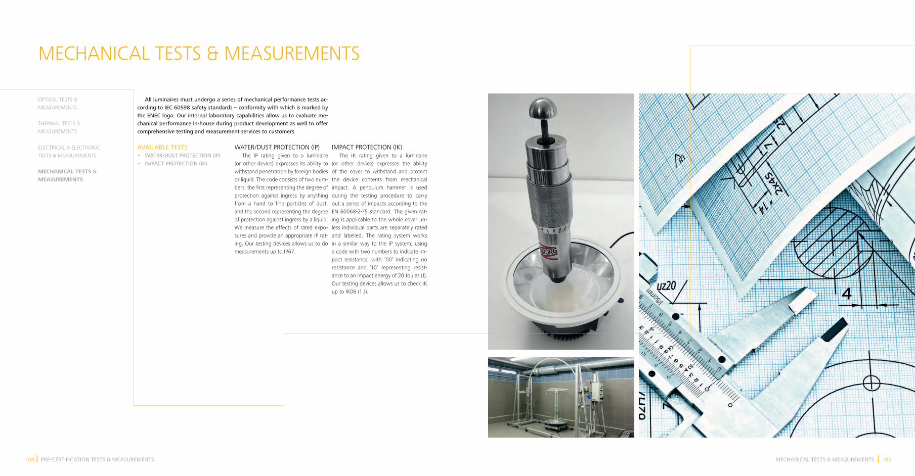
I 105 104 I MECHANICAL TESTS & MEASUREMENTSPRE-CERTIFICATION TESTS & MEASUREMENTS
MECHANICAL TESTS & MEASUREMENTS
All luminaires must undergo a series of mechanical performance tests ac-cording to IEC 60598 safety standards – conformity with which is marked by the ENEC logo. Our internal laboratory capabilities allow us to evaluate me-chanical performance in-house during product development as well to offer comprehensive testing and measurement services to customers.
OPTICAL TESTS & MEASUREMENTS
THERMAL TESTS & MEASUREMENTS
ELECTRICAL & ELECTRONIC TESTS & MEASUREMENTS
MECHANICAL TESTS & MEASUREMENTS
AVAILABLE TESTS• WATER/DUST PROTECTION (IP)• IMPACT PROTECTION (IK)
WATER/DUST PROTECTION (IP) The IP rating given to a luminaire (or other device) expresses its ability to withstand penetration by foreign bodies or liquid. The code consists of two num-bers: the first representing the degree of protection against ingress by anything from a hand to fine particles of dust, and the second representing the degree of protection against ingress by a liquid. We measure the effects of rated expo-sures and provide an appropriate IP rat-ing. Our testing devices allows us to do measurements up to IP67.
IMPACT PROTECTION (IK) The IK rating given to a luminaire (or other device) expresses the ability of the cover to withstand and protect the device contents from mechanical impact. A pendulum hammer is used during the testing procedure to carry out a series of impacts according to the EN 60068-2-75 standard. The given rat-ing is applicable to the whole cover un-less individual parts are separately rated and labelled. The rating system works in a similar way to the IP system, using a code with two numbers to indicate im-pact resistance, with ‘00’ indicating no resistance and ‘10’ representing resist-ance to an impact energy of 20 Joules (J). Our testing devices allows us to check IK up to IK06 (1 J).

THE LONG-TERM TEST LAB
THE LONG-TERM TEST (LTT) LAB We have developed an automated long-term testing system, the LTT lab, that can test the light output and elec-trical parameters such as input current, voltage, apparent power, active power, reactive power, and power factor, of 6 LED-based luminaires simultaneously. With up to 9 thermocouples per chan-nel, we can check even large luminaires. In addition, we can also test the dim-ming functionality of luminaires using analogue or DALI dimming. We use this testing system during the final stages of luminaire development as part of final characterisation, the results of which are included in such materials as datasheets.
Since both the hardware and software are developed by iLumTech, the func-tionality of the LTT lab can be extended and adjusted to upcoming new test reg-ulations and requirements.
KEY FEATURES• The light emitted by the luminaires under test is measured by sensors that detect relative lumen output. • Luminaires are powered by program-mable linear power supplies that ensure stable and high quality power supply and offer the possibility to simulate power line abnormalities.• The combined input power of all lumi-naires under test is limited to 500 W.
LTT LAB CAPABILITIES• Functionality test• Frequent switching test• Under-voltage test• Over-voltage test• Endurance test (IEC60598-1-12)• Dimming test (DALI, 0–10 V, 1–10 V)• Lifetime test
The use of Solid State Lighting (SSL) technology continues to grow rap-idly, and LED-based luminaires bring new challenges in testing and charac-terisation. Modern SSL luminaires offer additional capabilities in the control of light properties in comparison with conventional light sources. Therefore, the complexity of electronic design is much higher, and so also the demands on testing.
DALI APPROVAL
We have been a regular member of DALI since 2012 and actively par-ticipated in each DALI group meeting since the group’s establishment. This gives us the opportunity to influence the DALI standard itself and also certi-fication conditions for new products.
HOW IT WORKS AND WHY WE CAN APPROVE USE OF THE LOGO A DALI network consists of DALI-compatible controllers and one or more lighting devices such as drivers, dimmers, user-interfaces, sensors, and much more. The protocol allows for all of these devic-es to be addressed and controlled using individual, group, and scenic commands. Control possibilities include dimming, Tunable White regulation, RGB lighting, the addition of sensors, creation of both static and dynamic sequences, and even system monitoring.
DALI’s digital simplicity and flexibility enables the creation of solutions that are easy-to-use, robust, interoperable, and above all affordable. DALI has proven its reliability for many years, and will continue to develop and support the growing demands for professional lighting.
In 2014, a new logo and licensing pro-cess was agreed to define the condi-tions for proper usage of the DALI logo. Each new product must pass testing by an official DALI tester. Thanks to having our own DALI tester, we can perform DALI testing in-house. The basic DALI tester configuration can be extended for further testing, meaning we can provide even stricter testing than that required by the standards. We intend to become an official DALI testing house to simplify and shorten the DALI certifi-cation process for our customers.
If you want the DALI trademark to be applied to any developed product or device, you must ask a member of DALI WG. As an active member, we have ap-proval to use the logo on developed products that are compliant with the latest DALI standard. Furthermore, membership gives us direct access to the newest version of test sequences and standards, thus ensuring the most up-to-date testing conditions.

I 109 108 I THE APPROACH YOU TRULY DESERVETHE APPROACH YOU TRULY DESERVE
THE APPROACH YOU TRULY DESERVE
Our services and products are built around your needs and wishes. Every-thing else is just general guidance. Let us know what you need, how we can support you, and where you can utilise our capabilities. Feel free to contact us with any question and benefit from our fast responses, flexibility, and customer-oriented principles.
EXPERIENCED ENGINEERS Our engineers have experience in every field related to the development of lighting devices and their parts.
PROFESSIONAL OUTPUTS Technical documentation and meas-urement reports are professionally com-pleted and compiled ready for CE certifica-tion and entrance into serial production.
FULLY EQUIPPED R&D We have some of the best-equipped optical, thermal, electronic, and me-chanical laboratories in Europe.
CONFIDENTIAL ATTITUDE We have an NDA approach to all our work. The confidentiality of information about our cooperation and the projects we work on together is an essential part of our service.
FUTURE ORIENTED THINKING Thanks to our experience of the LED industry, all our development and engi-neering is done with the future in mind.
CONTINUOUS SERVICE Product development is a never-end-ing process. We will continue with you on this journey through optimisations, updates, and customisations.
PROVIDING THE PERFECT SOLUTION IS NOT JUST OUR JOB. IT IS OUR PASSION.