Body-Bias Scaling for GLOBALFOUNDRIES 22FDx Technology … · Body-Bias Scaling for GLOBALFOUNDRIES...
28
1 Body-Bias Scaling for GLOBALFOUNDRIES 22FDx Technology New Dimension to Explore the Design Ramya Srinivasan Tamer Ragheb GLOBALFOUNDRIES March 30-31, 2016 SNUG Silicon Valley
Transcript of Body-Bias Scaling for GLOBALFOUNDRIES 22FDx Technology … · Body-Bias Scaling for GLOBALFOUNDRIES...

SNUG 2016 1
Body-Bias Scaling for GLOBALFOUNDRIES 22FDx Technology New Dimension to Explore the Design Ramya Srinivasan Tamer Ragheb GLOBALFOUNDRIES
March 30-31, 2016 SNUG Silicon Valley

SNUG 2016 2
Agenda
Introducing 22FDX technology and platform Body-Biasing: A New Dimension in Design Closure Why we need Body-Bias Interpolation PrimeTime solution for Body-Bias Interpolation Results:
Accuracy vs Characterized libraries Conclusion

SNUG 2016 3
Agenda
Introducing 22FDX technology and platform Body-Biasing: A New Dimension in Design Closure Why we need Body-Bias Interpolation PrimeTime solution for Body-Bias Interpolation Results:
Accuracy vs Characterized libraries Conclusion

SNUG 2016 4
GLOBALFOUNDRIES 22FDX Technology
• What is 22FDX technology? – It is the new 22nm Fully
Depleted Silicon-on-Insulator (FDSOI) technology from GLOBALFOUNDRIES
• Delivers FinFET-like performance and power-efficiency at 28nm cost
• Integrated RF for reduced system cost and back-gate feature to reduce RF power
• Enables applications across mobile, IoT and RF markets
Bulk versus FDSOI
Planar Bulk Transistor Planar FDSOI Transistor with “green” Insulator layer
Effects of Body Biasing in Bulk Transistor and FDSOI Transistor

SNUG 2016 5
GLOBALFOUNDRIES 22FDx Technology
• Body-biasing Provides Greatest Design Flexibility – Enables Body Bias (BB) with minimal leakage impact – Forward body-bias (FBB) enables low voltage operation – Reverse body-bias (RBB) enables low leakage
• Improve within die or die-to-die uniformity • Lower Leakage due to insulator layer • FDSOI variability is smaller across die due to lower doping effort • Dynamic body-biasing enables active tradeoff of performance vs. power
– Software-controlled transistor body-biasing for flexible trade-off between performance and power
– Post-silicon tuning/trimming
Why 22FDx Technology? -2V to +2V Body-Biasing

SNUG 2016 6
Body-biasing Power/Performance Trade-off
Max Frequency
Leakage Power
Reverse Body-bias (RBB)
Forward Body-bias (FBB)
Maximum Performance Operating Mode
Minimum Leakage In Standby Mode

SNUG 2016 7
GLOBALFOUNDRIES 22FDX Technology
• Bias voltage is applied to P-well and N-well
• Reverse Body Bias (RBB)
– raising VT of device – nMOS neg. substrate voltage,
pMOS pos. substrate voltage
• Forward Body Bias (FBB)
– lowering VT of device – nMOS pos. substrate voltage,
pMOS neg. substrate voltage
RBB versus FBB
flipped well

SNUG 2016 8
Agenda
Introducing 22FDX technology and platform Body-Biasing: A New Dimension in Design Closure Why we need Body-Bias Interpolation PrimeTime solution for Body-Bias Interpolation Results:
Accuracy vs Characterized libraries Conclusion

SNUG 2016 9
What is Body-biasing?
• Substrate biasing is a low power technique – For tuning performance and static power consumption of a CMOS device
• Body-biasing applied through voltage variation on PWELL and NWELL terminal • Same implementation can be timed with different Bias voltages resulting in
different performance results • Different Body-Biasing domains on one chip are enabling new design
architectures and design styles • Due to the variation in Body Bias as a new variable, now the corners are PVTB
(Process/Voltage/Temperature/Body Bias)
A New Dimension in Design Closure
PVT + BIAS PVTB
Bulk Flow New Step for 22FDX
Library Char + POCV/LVF variability
Lib char with BB (Added
corners)
SNUG 2016 10
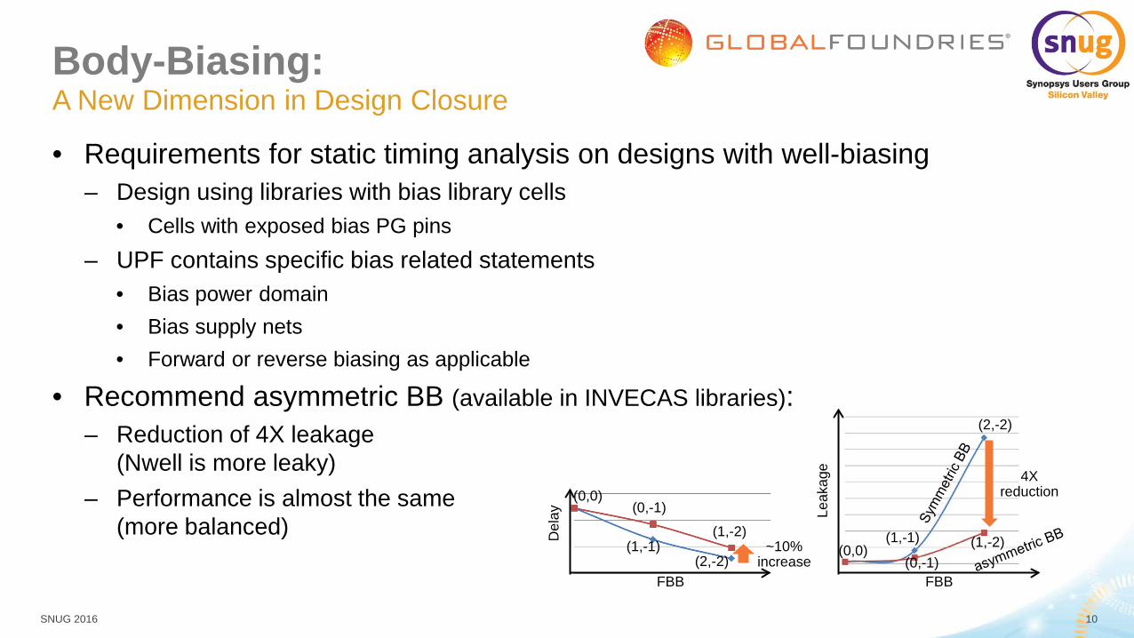
Body-Biasing:
• Requirements for static timing analysis on designs with well-biasing – Design using libraries with bias library cells
• Cells with exposed bias PG pins – UPF contains specific bias related statements
• Bias power domain • Bias supply nets • Forward or reverse biasing as applicable
• Recommend asymmetric BB (available in INVECAS libraries): – Reduction of 4X leakage
(Nwell is more leaky) – Performance is almost the same
(more balanced)
A New Dimension in Design Closure
FBB
Leak
age
4X reduction
(0,0) (0,-1)
(1,-2)
(2,-2)
(1,-1)
FBB
Del
ay (0,0)
(0,-1)
(1,-2)
(2,-2) (1,-1) ~10%
increase
SNUG 2016 11
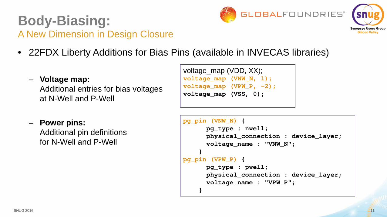
Body-Biasing:
• 22FDX Liberty Additions for Bias Pins (available in INVECAS libraries) – Voltage map:
Additional entries for bias voltages at N-Well and P-Well
– Power pins: Additional pin definitions for N-Well and P-Well
A New Dimension in Design Closure
pg_pin (VNW_N) { pg_type : nwell; physical_connection : device_layer; voltage_name : "VNW_N"; } pg_pin (VPW_P) { pg_type : pwell; physical_connection : device_layer; voltage_name : "VPW_P"; }
voltage_map (VDD, XX); voltage_map (VNW_N, 1); voltage_map (VPW_P, -2); voltage_map (VSS, 0);
SNUG 2016 12
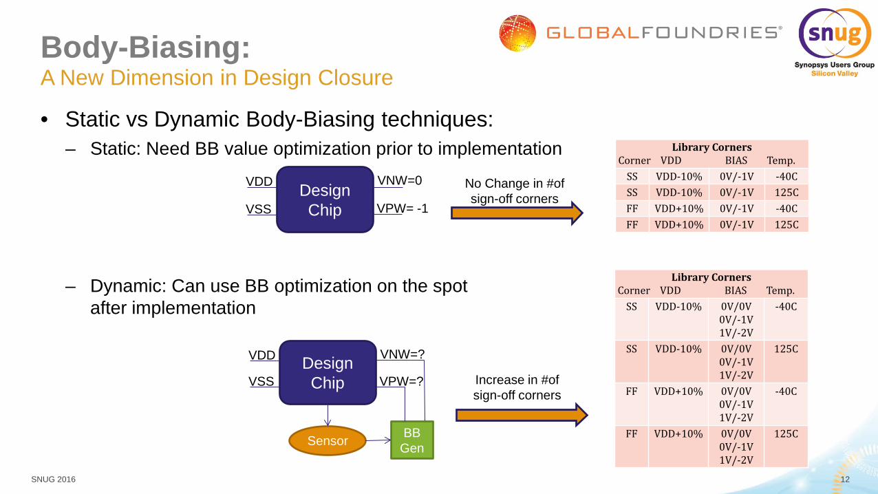
Body-Biasing:
• Static vs Dynamic Body-Biasing techniques: – Static: Need BB value optimization prior to implementation
– Dynamic: Can use BB optimization on the spot after implementation
A New Dimension in Design Closure
Design Chip
VDD
VSS
VNW=0
VPW= -1
No Change in #of sign-off corners
Library Corners Corner VDD BIAS Temp.
SS VDD-10% 0V/-1V -40C SS VDD-10% 0V/-1V 125C FF VDD+10% 0V/-1V -40C FF VDD+10% 0V/-1V 125C
Library Corners Corner VDD BIAS Temp.
SS VDD-10% 0V/0V 0V/-1V 1V/-2V
-40C
SS VDD-10% 0V/0V 0V/-1V 1V/-2V
125C
FF VDD+10% 0V/0V 0V/-1V 1V/-2V
-40C
FF VDD+10% 0V/0V 0V/-1V 1V/-2V
125C
Design Chip
VDD
VSS
VNW=?
VPW=?
Sensor BB Gen
Increase in #of sign-off corners

SNUG 2016 13
Body-Bias Flow
• Scaling groups are created using the libraries at different bias-voltages.
• Libraries characterized at different voltages are grouped together to be used in the design for scaling
• set link_path “* Lib1-0.72V-m40c-0-0.db“ • define_scaling_lib_groups “Lib1-0.72V-m40c-0-0.db Lib1-0.72V-m40c-0-M1.db Lib1-0.72V-m40c-0-M2.db
Lib1-0.72V-m40c-1-0.db Lib1-0.72V-m40c-1-M1.db Lib1-0.72V-m40c-1-M2.db”
Usage flow with scaling libraries
Lib1: 0.72v,-40c (0v,0v) Lib2: 0.72v,-40c (0v,-1v)
Lib6: 0.72v,-40c (1v,-2v)
Lib3: 0.72v,-40c (0v,-2v)
Lib5: 0.72v,-40c (1v,-1v) Lib4: 0.72v,-40c (1v,0v)
VNW
VPW
1,0 0,0
1,-1 0,-1
0,-2 1,-2

SNUG 2016 14
Body-Bias Flow
• Define the connectivity to the bias PG pins – set_voltage 0.72 -min 0.72 -object_list VDD – set_voltage 0 -min 0 -object_list VSS – set_voltage 0.5 -min 0.5 -object_list NET_BIAS_VNW – set_voltage -1.0 -min -1.0 -object_list NET_BIAS_VPW
• STA Settings – waveform propagation enabled – SI analysis turned off – PBA Mode
• Primetime version – K-2016.06 (Beta version)
Usage flow with scaling libraries
Read netlist and link design
Scaling library groups and enable bias voltage scaling
Load UPF (has bias PG info)
Read SDC and set_voltage for bias pins
Update timing and generate reports

SNUG 2016 15
Body-Bias Scaling Validation • Bias voltage scaling is validated with spice accuracy correlation for uncoupled
path delay • Bias scaling validated for the 9 points (orange points) • Bias interpolation validated with different combinations of scaling libraries (blue points) • Blue points are pre-characterized points • For each body-bias value (orange points) STA and spice correlation was carried out with
– All 6 libraries (all blue points) – 5 libraries – 4 libraries – 3 libraries
VPW
1,0 0,0
1,-1 0,-1
0,-2 1,-2
VNW

SNUG 2016 16
Validation Methodology
• Primetime Simulation Link – perform path-based uncoupled SPICE analysis – The SimLink commands supports the body bias voltage in SPICE deck generation
• Synopsys FineSim - 2015.06-SP1-4
Primetime Simulation Link
sim_setup_library
sim_setup_simulator
Select paths for correlation (PBA)
sim_validate_path
Post process correlation results
Set up the SPICE models for simulation by specifying the library name, subcircuit directory name, and header file name.
Specify the name of the HSPICE simulator executable (FineSim), simulator options for comparisons between PrimeTime and the Finesim.
Perform path-based uncoupled SPICE analysis on a specified path segment and compares the simulation results against the static timing results.

SNUG 2016 17
Testcase setup
• Testcase: falcon_neon (part of ARM Cortex-A9) • Cell-count: 150K (std-cells) • Setup Analysis with PBA mode • Forward-Bias Mode • Placement Utilization: 65% • Library: 8T CNRX • Metal Stack: 8M layers • PNR MCMM Scenarios
– TT.0P80V-0P0V-0P0V.25C_FuncCmax – TT.0P80V-0P0V-M1P0V.25C_FuncCmax – TT.0P80V-1P0V-M2P0V.25C_FuncCmax
• Cell Types: wcl and wcs

SNUG 2016 18
Implementation Details Place & Route with ICC • Based on Multi-Voltage aware Synopsys reference scripts - UPF and bias-specific scenario settings same as for synthesis
- Floorplan includes : Additional physical cells to support Bias-Supply from external : Voltage-Areas for each Bias-Domain
- Power Planning Includes Bias-Routes - Fill Insertion has to be
:Bias-Domain aware / VT aware - Special NDR Rules on Bias-Nets
(HV rules) - CNRX Placement
- To reduce the layout dependent effects
TapCells
S D S Abut Abut D Abut Spacing
Filler Cell

SNUG 2016 19
Implementation Details
• Bias Tap-Cells – Supply N-Wells and P-Wells with
Bias-Voltages from an external source – Are ideally placed in columns so minimize
routing overhead due to additional Bias-Straps – Have to fulfill maximum distance rules
between each other
• Bias-Routes – Connect NW and PW separately from VDD
and VSS mesh – BB mesh connection using UPF flow – Provide Bias-Voltages to Bias-Tap-Cells – Can be connected to a on-die Bias-Voltage
generator
Place & Route with ICC: Floor/Power-Planning
NET_BIAS_2_VNW Metal3-Strap
NET_BIAS_2_VPW Metal3-Strap

SNUG 2016 20
Results Bias Scaling correlation to SPICE with 3 libraries
1,0 0,0
1,-1 0,-1
0,-2 1,-2
VNW
VPW
0.5V,-1.5V
• To get the best accuracy using ONLY the 3 libraries provided by Invecas GLOBALFOUNDRIES recommends body bias scaling along the purple line

SNUG 2016 21
Results Bias Scaling Correlation to SPICE with 4 libraries
1,0 0,0
1,-1 0,-1
0,-2 1,-2
VNW
VPW
0.5V,-1.5V
• For better accuracy, use the 4 corner libraries if available to cover the VNW/VPW scaling space

SNUG 2016 22
Results Bias Scaling Correlation to SPICE with 6 libraries
1,0 0,0
1,-1 0,-1
0,-2 1,-2
VNW
VPW
0.5V,-1.5V
• For best accuracy (Synopsys Recommendation), use the 6 corners libraries if available to cover the VNW/VPW scaling space

SNUG 2016 23
Results Bias Scaling correlation to SPICE with 3 libraries
1,0 0,0
1,-1 0,-1
0,-2 1,-2
VNW
VPW
• To get the best accuracy using ONLY the 3 libraries provided by Invecas GLOBALFOUNDRIES recommends body bias scaling along the purple line
0.0V,-0.5V

SNUG 2016 24
Results Bias Scaling Correlation to SPICE with 4 libraries
1,0 0,0
1,-1 0,-1
0,-2 1,-2
VNW
VPW
• For better accuracy, use the 4 corner libraries if available to cover the VNW/VPW scaling space
0.0V,-0.5V

SNUG 2016 25
Results Bias Scaling Correlation to SPICE with 6 libraries
1,0 0,0
1,-1 0,-1
0,-2 1,-2
VNW
VPW
• For best accuracy (Synopsys Recommendation), use the 6 corners libraries if available to cover the VNW/VPW scaling space
0.0V,-0.5V

SNUG 2016 26
Results Summary
• Bias scaling analysis with 6 libraries (Synopsys Recommendation) correlates very closely to SPICE with maximum percentage error close to 2.5%
• Bias scaling with 4 libraries may be a reasonable compromise with acceptable percentage of error – depending on the customer max error target
• Using the current Invecas offering (3 libraries), bias scaling is possible ONLY along the purple line if the amount of error is acceptable to customer
• Bias scaling accuracy can be different from one library to another – Customer/IP vendor optimization of # of characterized library vs max error
1,0 0,0
1,-1 0,-1
0,-2 1,-2
VNW
VPW
0.0V,-0.5V
0.5V,-1.5V

SNUG 2016 27
Conclusion
• Body Bias Interpolation algorithm works accurately in PrimeTime: – Accurate correlation seen between Scaled STA runs with 6 libraries vs SPICE
• Synopsys recommendation is to use 6 libraries for body-bias scaling in STA flows
• GLOBALFOUNDRIES will deploy the Body-Bias scaling capability in Primetime in the Digital reference flows
• Future work: GLOBALFOUNDRIES is working with Synopsys to include BB Interpolation in upstream tools “ICC/ICCII”

SNUG 2016 28
Thank You