Bluetooth Overview.ppt
65
Bluetooth Owen Garmire and Seila Kheang CSE 466 Fall 2001 http://www.cs.washington.edu/homes/seila/ bluetooth.ppt
Transcript of Bluetooth Overview.ppt
Bluetooth
Owen Garmire and Seila KheangCSE 466 Fall 2001
http://www.cs.washington.edu/homes/seila/bluetooth.ppt
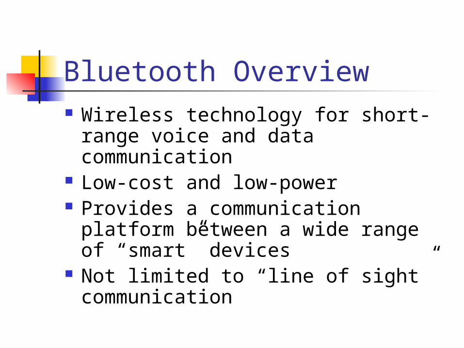
Bluetooth Overview Wireless technology for short-range
voice and data communication Low-cost and low-power Provides a communication platform
between a wide range of “smart” devices
Not limited to “line of sight” communication
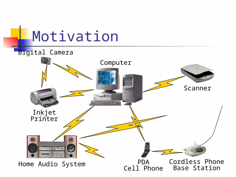
Motivation
PDACell Phone
Cordless PhoneBase Station
InkjetPrinter
Scanner
Home Audio System
Computer
Digital Camera
Bluetooth Applications Automatic synchronization between
mobile and stationary devices Connecting mobile users to the
internet using bluetooth-enabled wire-bound connection ports
Dynamic creation of private networks
Synchronization Keep data on different devices
synchronized without using a cable Example:
Walk into office and have your PDA synch with your laptop on your desk without even taking your PDA out of your briefcase
Connecting to Internet Being able to gain access to the
Internet by using “Bluetooth access points” Access point is used as a gateway to the
internet Both the access point and the device are
Bluetooth-enabled An example of Service Discovery Protocol
Access point provides a service to the device
Ad Hoc Networks Up to 8 devices can be actively
connected in master/slave configuration
Piconets can be combined to form scatternets providing unlimited device connectivity
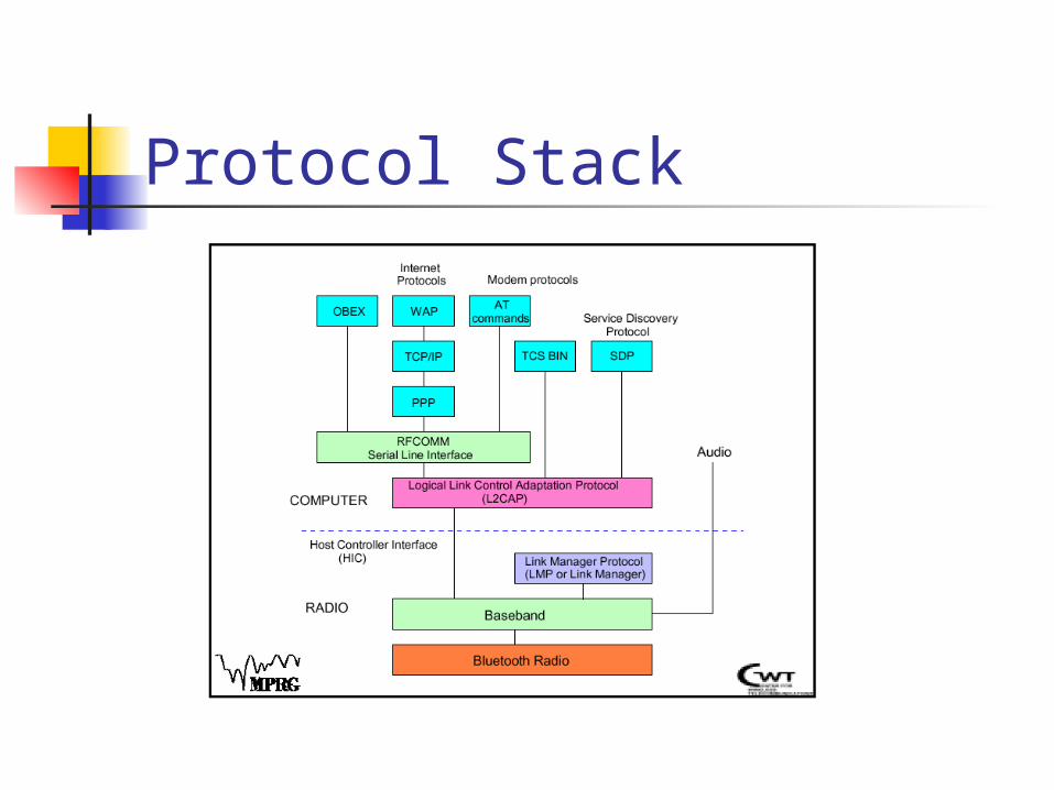
Protocol Stack
Bluetooth Radio Uses 2.4 GHz ISM band spread
spectrum radio (2400 – 2483.5 MHz) Advantages
Free Open to everyone worldwide
Disadvantages Can be noisy (microwaves, cordless
phones, garage door openers)
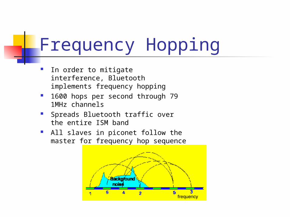
Frequency Hopping In order to mitigate interference,
Bluetooth implements frequency hopping
1600 hops per second through 79 1MHz channels
Spreads Bluetooth traffic over the entire ISM band
All slaves in piconet follow the master for frequency hop sequence
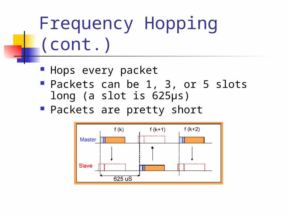
Frequency Hopping (cont.) Hops every packet Packets can be 1, 3, or 5 slots long (a slot
is 625µs) Packets are pretty short
Baseband Layer Provides in-order delivery of byte
streams Handles Frequency Hop Sequences for
Synchronization and Transmission Establishes Links
Synchronous Connection Oriented (SCO) Asynchronous Connection-Less (ACL)
Provides functionality to determine nearby Bluetooth devices
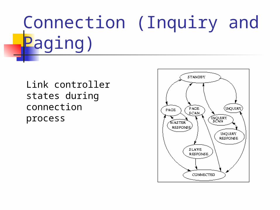
Connection (Inquiry and Paging)
Link controller states during connection process
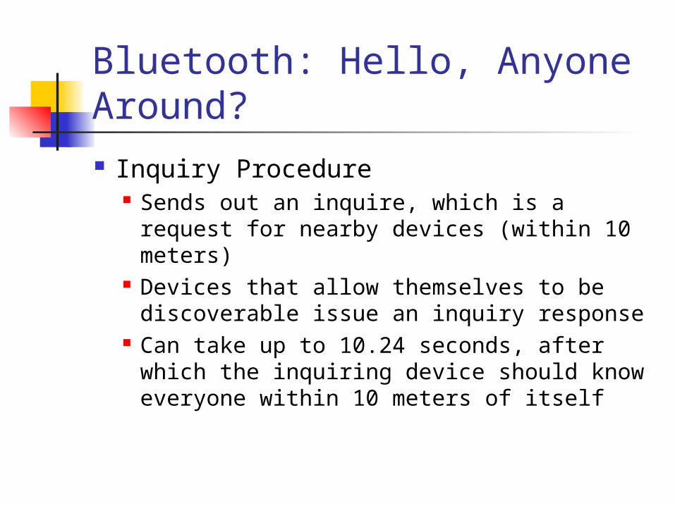
Bluetooth: Hello, Anyone Around? Inquiry Procedure
Sends out an inquire, which is a request for nearby devices (within 10 meters)
Devices that allow themselves to be discoverable issue an inquiry response
Can take up to 10.24 seconds, after which the inquiring device should know everyone within 10 meters of itself
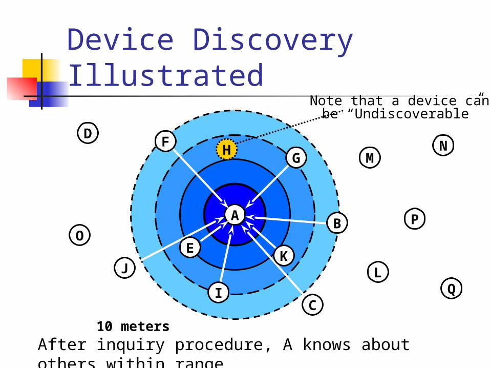
Device Discovery Illustrated
D
A
10 meters
H MN
L
PO
Q
B
C
F
KJ
G
I
E
H
Note that a device canbe “Undiscoverable”
After inquiry procedure, A knows about others within range
Issues with Inquire Messages Are the inquirer transmitting and the
receiver listening on the same frequency? Since they are not yet connected, they are on
totally different hop sequences, and most likely on different channels
If they are on the same frequency, what if they are on a noisy channel? Bluetooth provides the capability for receivers
to issue multiple inquiry responses
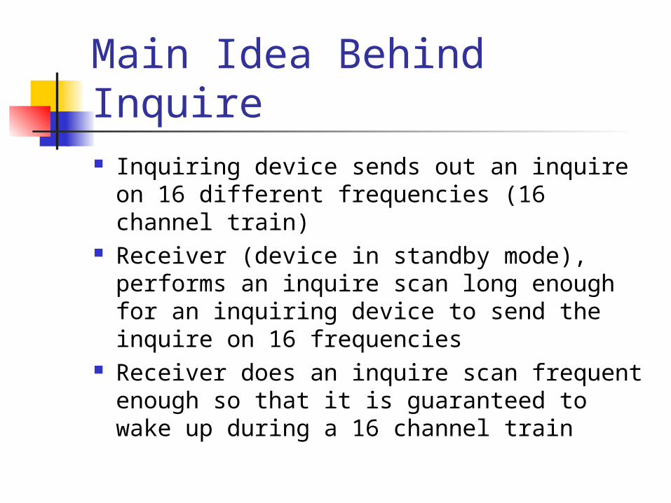
Main Idea Behind Inquire Inquiring device sends out an inquire on
16 different frequencies (16 channel train) Receiver (device in standby mode),
performs an inquire scan long enough for an inquiring device to send the inquire on 16 frequencies
Receiver does an inquire scan frequent enough so that it is guaranteed to wake up during a 16 channel train
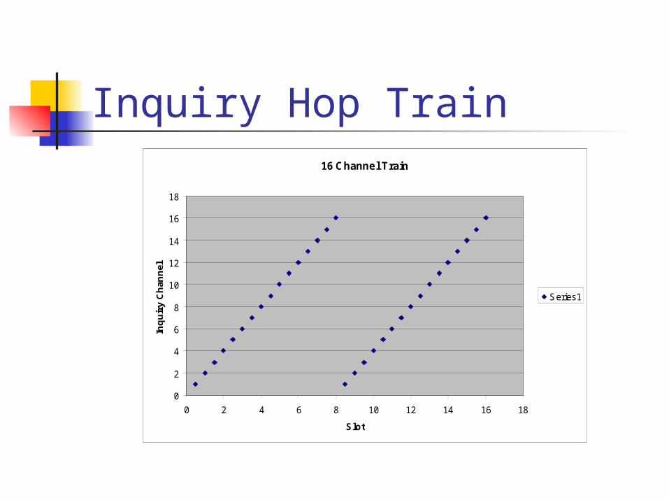
Inquiry Hop Train16 Channel Train
0
2
4
6
8
10
12
14
16
18
0 2 4 6 8 10 12 14 16 18
Slot
Inqu
iry
Cha
nnel
Series1
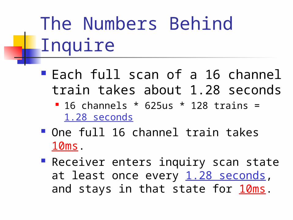
The Numbers Behind Inquire Each full scan of a 16 channel train
takes about 1.28 seconds 16 channels * 625us * 128 trains = 1.28
seconds One full 16 channel train takes 10ms. Receiver enters inquiry scan state at
least once every 1.28 seconds, and stays in that state for 10ms.
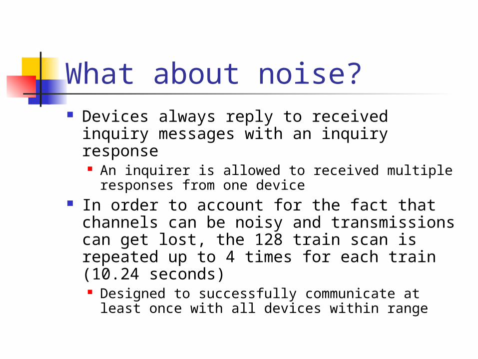
What about noise? Devices always reply to received inquiry
messages with an inquiry response An inquirer is allowed to received multiple
responses from one device In order to account for the fact that
channels can be noisy and transmissions can get lost, the 128 train scan is repeated up to 4 times for each train (10.24 seconds) Designed to successfully communicate at least
once with all devices within range
Inquiry Uses 32 inquire channels to send out
inquiry messages Send out inquiry on 32 channels,
broken up into 2 inquiry hop trains (16 different channels to transmit packets)
Intended to catch a device in inquiry scan mode on one of the 32 inquire channels
Inquiry Scan A device periodically listens for inquiry
packets at a single frequency – chosen out of 16 frequencies Inquiry hop sequence depends on device
address Stays in the state long enough for a
inquiring device to cover 16 frequencies Will re-enter inquiry scan state even
after responding to an inquire
Inquiry Response When radio receives inquire, it will wait
between 0 and .32 seconds before sending an FHS packet as a response This is done to avoid collision with another radio
that also wants to send an FHS packet FHS Packet contains:
Device ID Clock
After inquiring radio is done with inquiring procedure, it knows all of the radios (that are discoverable) within range
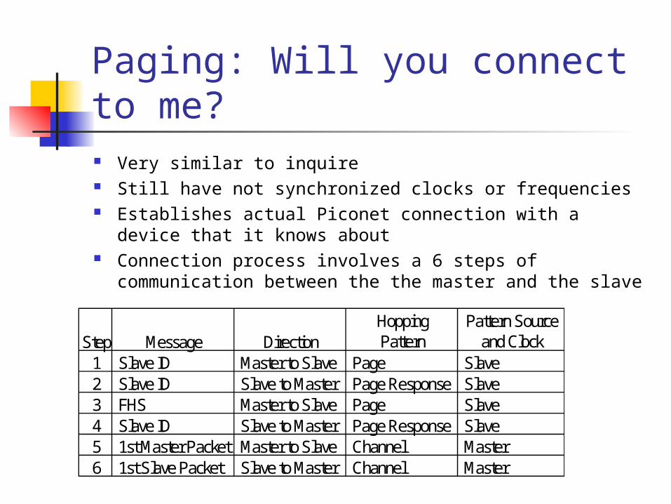
Paging: Will you connect to me? Very similar to inquire Still have not synchronized clocks or frequencies Establishes actual Piconet connection with a device that
it knows about Connection process involves a 6 steps of
communication between the the master and the slave
Step Message DirectionHoppingPattern
Pattern Sourceand Clock
1 Slave ID Master to Slave Page Slave2 Slave ID Slave to Master Page Response Slave3 FHS Master to Slave Page Slave4 Slave ID Slave to Master Page Response Slave5 1st Master Packet Master to Slave Channel Master6 1st Slave Packet Slave to Master Channel Master
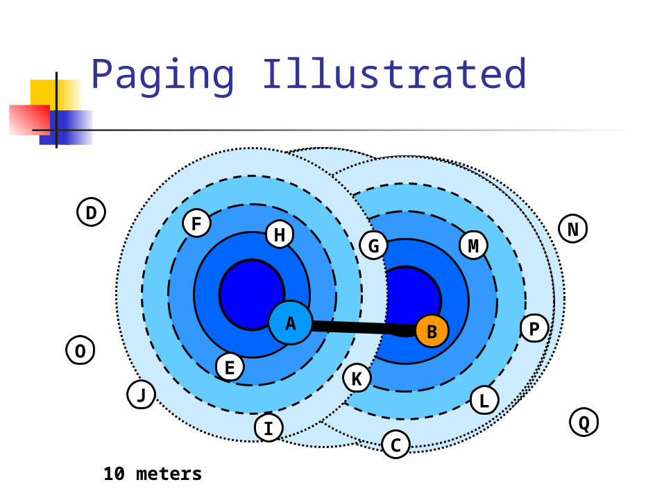
Paging Illustrated
D
E
F H G
I
KJ
C
MN
L
PO
Q
BBAAA
10 meters
Step 1: The Page Command Device broadcasts a page message
out to the device that it wants to set up a connection with Does this in a similar manner as
inquire messages (on 2 frequency trains of 16 frequencies each)
Once the device receives a page response, it will stop paging and move on to step 2
Paging: Steps 2 & 3 Step 2: In the page response, an
acknowledgement is sent back to the master containing the slave ID
Step 3: In the master response, the frequency hopping generator is stopped and the master issues an FHS packet to the slave
Paging: Step 4 The slave issues a final slave
response transmission that is aligned to the slave’s native clock
Using the data from the FHS packet, the slave calculates adopts the master’s frequency hopping pattern and synchronizes to its clock
Paging: Step 5 When the master receives the
packet, it jumps back to its frequency hopping pattern and assigns the slave an Active Member Address (AMA) for the piconet
Master sends out a poll packet to ensure that the slave is on its frequency hopping pattern
Paging: Step 6 Once the slave receives the poll packet,
the slave replies with any kind of packet to ensure that it is on the right channel
The acknowledgement must be received by the Master within the timeout period
At the conclusion of step 6, a new synchronized connection is established between the master and the slave
Link Manager Performs all link creation, management, and
termination operations Responsible for all the physical link resources in
the system Handles the control and negotiation of packet sizes
used when transmitting data Controls Operation Modes for devices in a piconet Sets up, terminates, and manages baseband
connections between devices Establishes different types of links dependent on
requests from the L2CAP layer Synchronous Connection-Oriented (SCO) Asynchronous Connection-Less (ACL)
Asynchronous Connection-Less (ACL) Designed for data traffic Packet switched connection where data
is exchanged sporadically as and when data is available from higher up the stack
Data integrity is checked through error checking and retransmission
One ACL link between a master and a slave
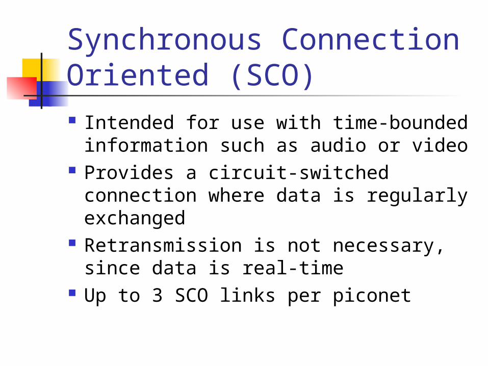
Synchronous Connection Oriented (SCO) Intended for use with time-bounded
information such as audio or video Provides a circuit-switched
connection where data is regularly exchanged
Retransmission is not necessary, since data is real-time
Up to 3 SCO links per piconet
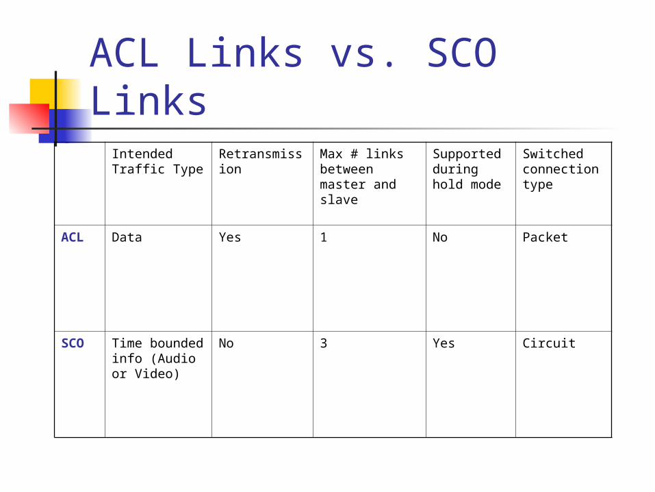
ACL Links vs. SCO LinksIntended Traffic Type
Retransmission
Max # links between master and slave
Supported during hold mode
Switched connection type
ACL Data Yes 1 No Packet
SCO Time bounded info (Audio or Video)
No 3 Yes Circuit
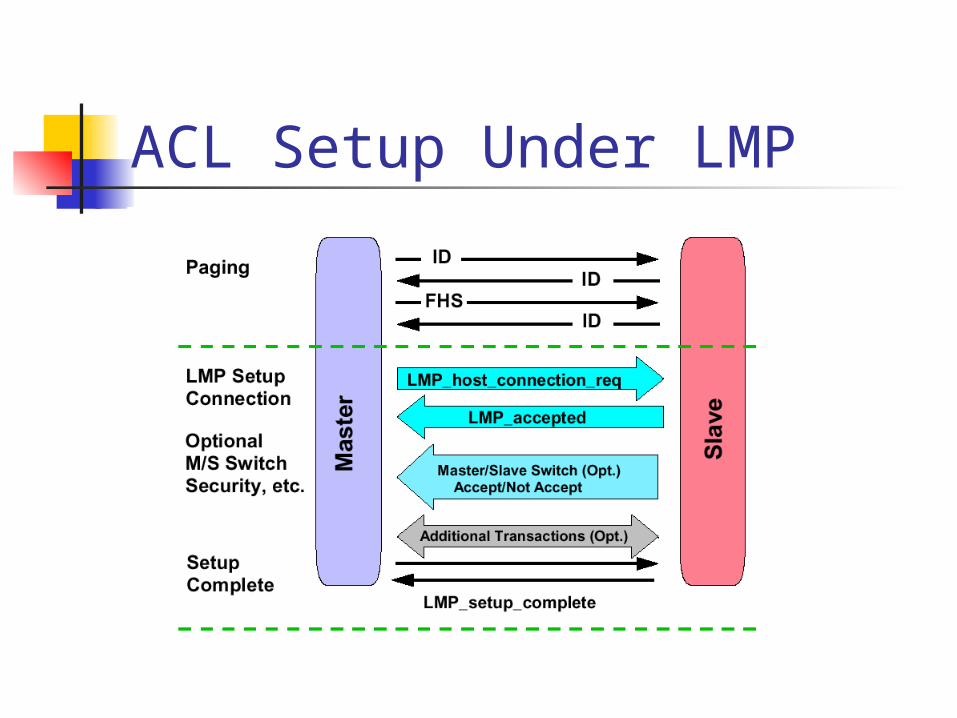
ACL Setup Under LMP
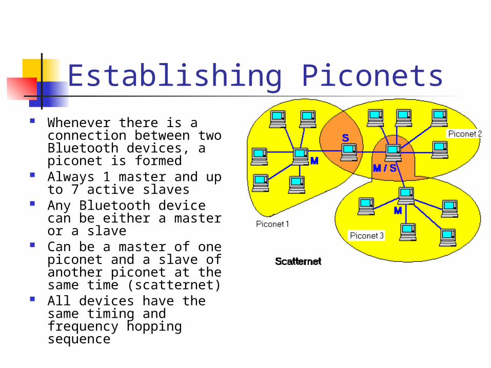
Establishing Piconets Whenever there is a
connection between two Bluetooth devices, a piconet is formed
Always 1 master and up to 7 active slaves
Any Bluetooth device can be either a master or a slave
Can be a master of one piconet and a slave of another piconet at the same time (scatternet)
All devices have the same timing and frequency hopping sequence
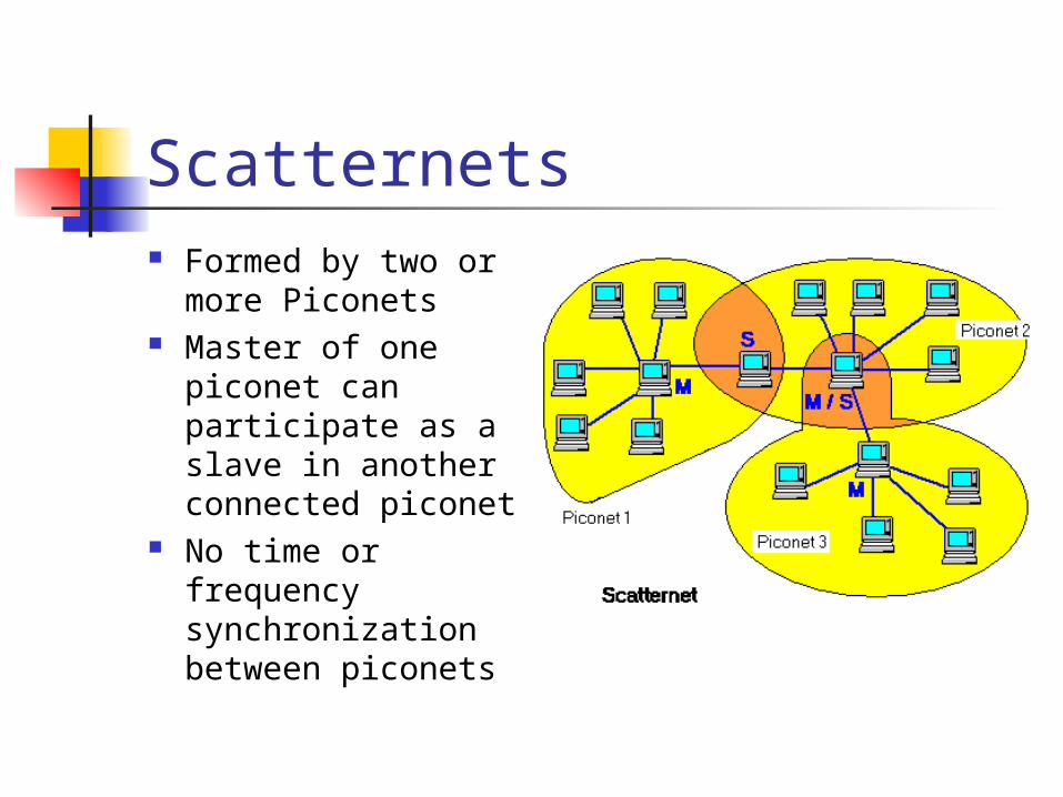
Scatternets Formed by two or
more Piconets Master of one
piconet can participate as a slave in another connected piconet
No time or frequency synchronization between piconets
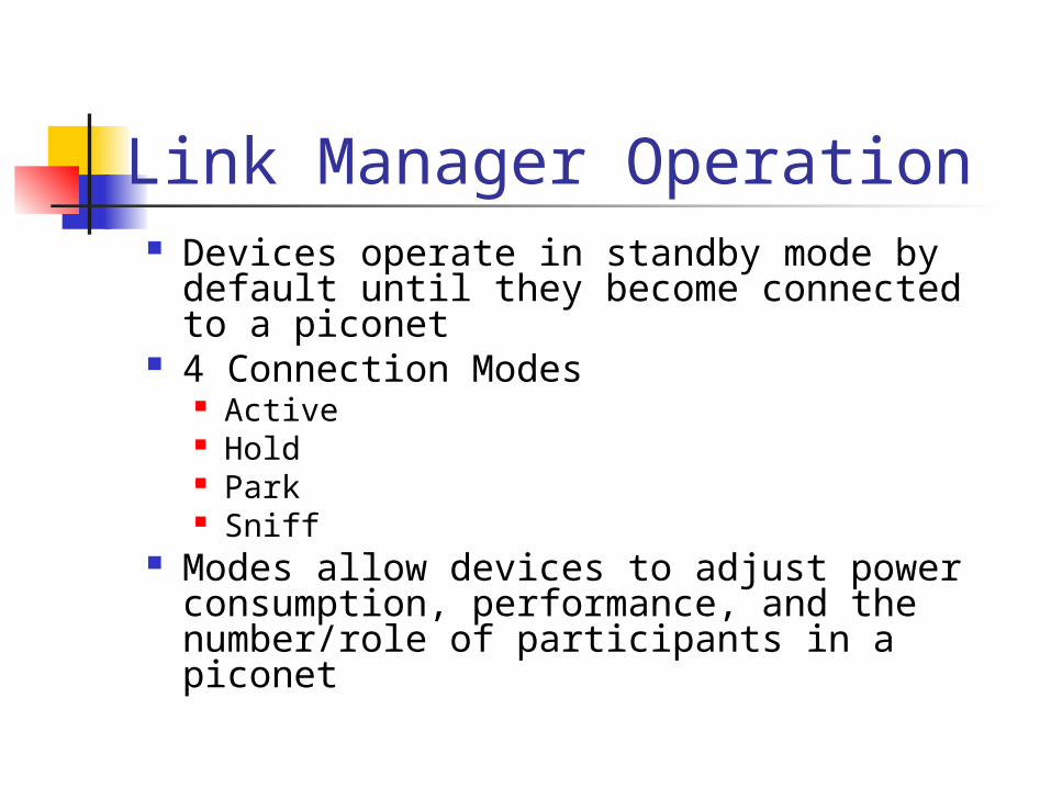
Link Manager Operation Devices operate in standby mode by
default until they become connected to a piconet
4 Connection Modes Active Hold Park Sniff
Modes allow devices to adjust power consumption, performance, and the number/role of participants in a piconet
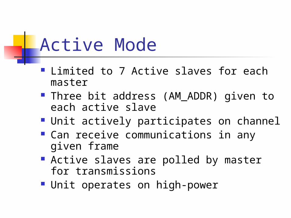
Active Mode Limited to 7 Active slaves for each master Three bit address (AM_ADDR) given to
each active slave Unit actively participates on channel Can receive communications in any given
frame Active slaves are polled by master for
transmissions Unit operates on high-power
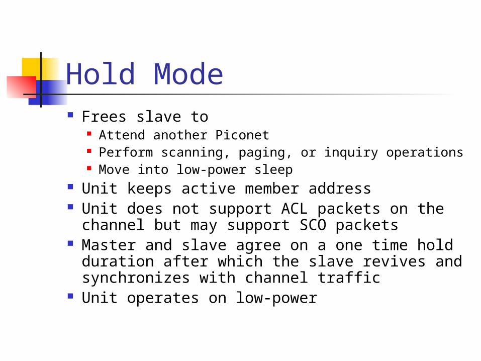
Hold Mode Frees slave to
Attend another Piconet Perform scanning, paging, or inquiry operations Move into low-power sleep
Unit keeps active member address Unit does not support ACL packets on the
channel but may support SCO packets Master and slave agree on a one time hold
duration after which the slave revives and synchronizes with channel traffic
Unit operates on low-power
Sniff Mode Very similar to hold mode Slave is freed for reoccurring fixed
time intervals Master can only communicate
during arranged “sniff” time slots
Park Mode Parked unit gives up active member
address and is assigned 8 bit Parked member address (PM_ADDR)
– allows master to unpark slave 8 bit Access request address (AR_ADDR) –
allows slave to ask master to unpark it Unit stays synchronized to channel Operates in very low-power sleep
Park Mode (cont.) Provides the ability to connect
more than 7 devices to a master (8 bit PM_ADDR allows 255 parked devices)
Active and Parked slaves can be switched in and out to allow many connections to a single piconet
Park Mode (cont.) Master establishes a beacon channel and
beacon interval when a slave is parked Parked slave wakes up at regular beacon
interval to Maintain synchronization Listen for “broadcast” messages (packets with
all zero AM_ADDR) Potentially make access request to master
through (AR_ADDR)
Park Mode (cont.) Beacon slots must have at least
“null” master-to-slave traffic Master-to-slave transmissions may
extend over multiple beacon slots
Security Link manager provides mechanism
used by devices at either end of a link for Negotiating encryption mode Coordinating encryption keys
Baseband handles encryption and key generation
Host Controller Interface (HCI) Most Bluetooth systems consist of two
processors: The higher layers of the protocol stack (L2CAP,
SDP, RFCOMM) are run on the host device’s processor
The lower layers of the protocol stack (Baseband and radio) are run on specific Bluetooth hardware
HCI provides an interface between the higher and the lower layers of the protocol stack
HCI Flow Control Main function of the Host Controller
Interface Many times higher layer protocols
have data rates much larger than data rate across Bluetooth radio and air interfaces Also need to handle the reverse situation
when the host cannot accept data as fast as the Bluetooth module can send it
Two Pieces of HCI Host controller resides on
Bluetooth hardware accepting communications over the physical bus (radio and air)
HCI Driver resides on the host accepting communications from higher layer protocols
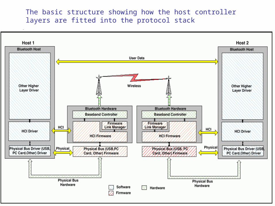
The basic structure showing how the host controller layers are fitted into the protocol stack
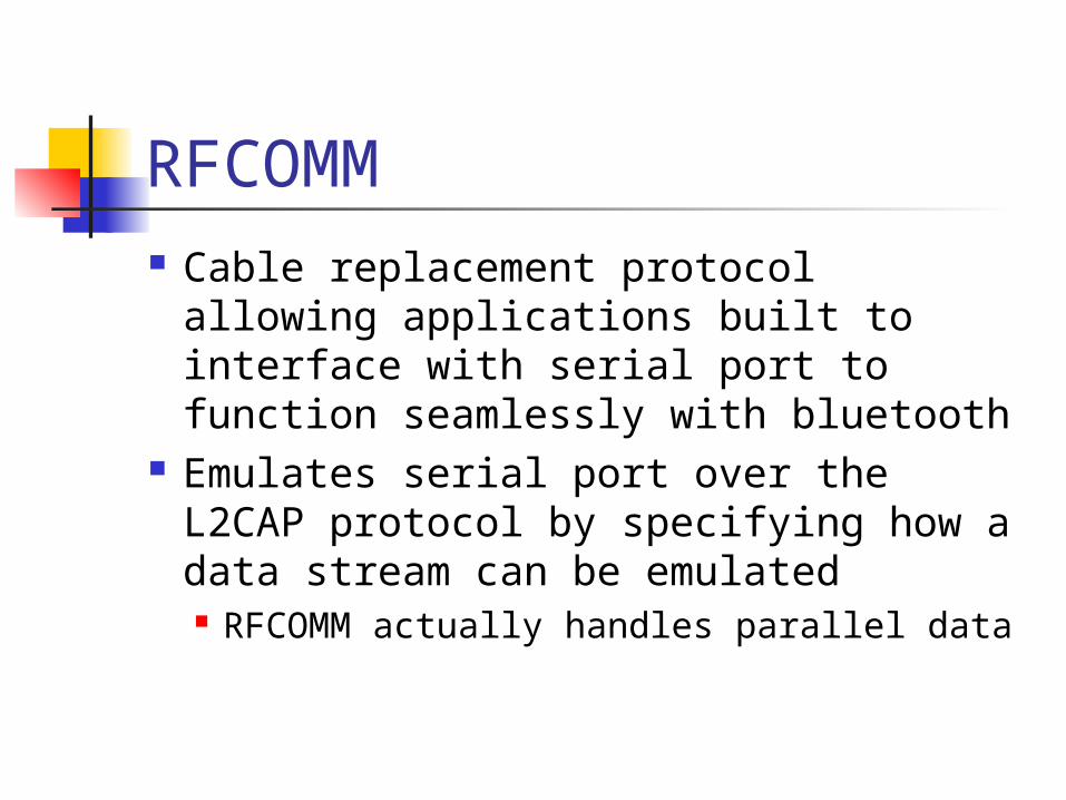
RFCOMM Cable replacement protocol
allowing applications built to interface with serial port to function seamlessly with bluetooth
Emulates serial port over the L2CAP protocol by specifying how a data stream can be emulated RFCOMM actually handles parallel data
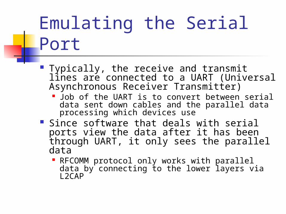
Emulating the Serial Port Typically, the receive and transmit lines
are connected to a UART (Universal Asynchronous Receiver Transmitter) Job of the UART is to convert between serial
data sent down cables and the parallel data processing which devices use
Since software that deals with serial ports view the data after it has been through UART, it only sees the parallel data RFCOMM protocol only works with parallel data
by connecting to the lower layers via L2CAP
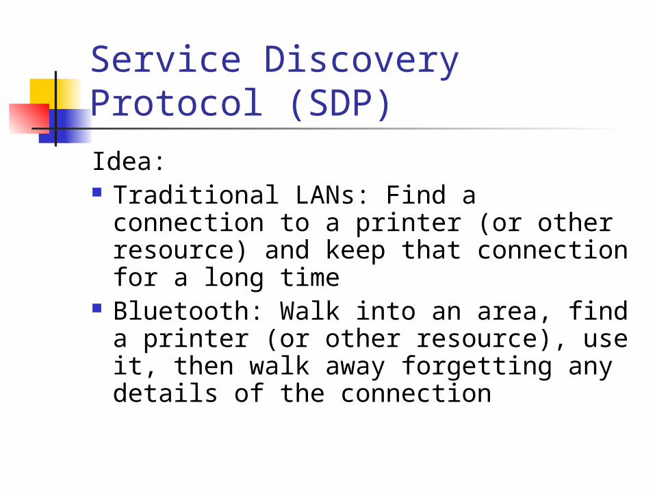
Service Discovery Protocol (SDP)Idea: Traditional LANs: Find a connection
to a printer (or other resource) and keep that connection for a long time
Bluetooth: Walk into an area, find a printer (or other resource), use it, then walk away forgetting any details of the connection
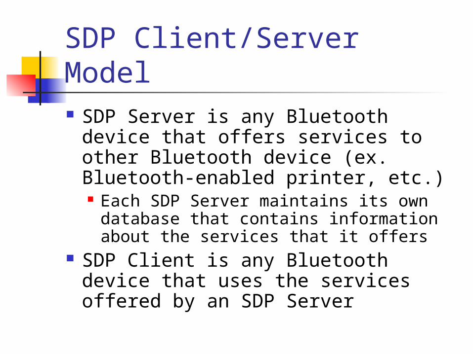
SDP Client/Server Model SDP Server is any Bluetooth device
that offers services to other Bluetooth device (ex. Bluetooth-enabled printer, etc.) Each SDP Server maintains its own
database that contains information about the services that it offers
SDP Client is any Bluetooth device that uses the services offered by an SDP Server
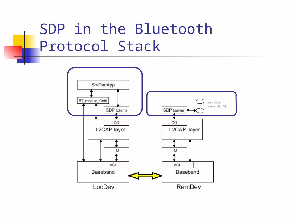
SDP in the Bluetooth Protocol Stack
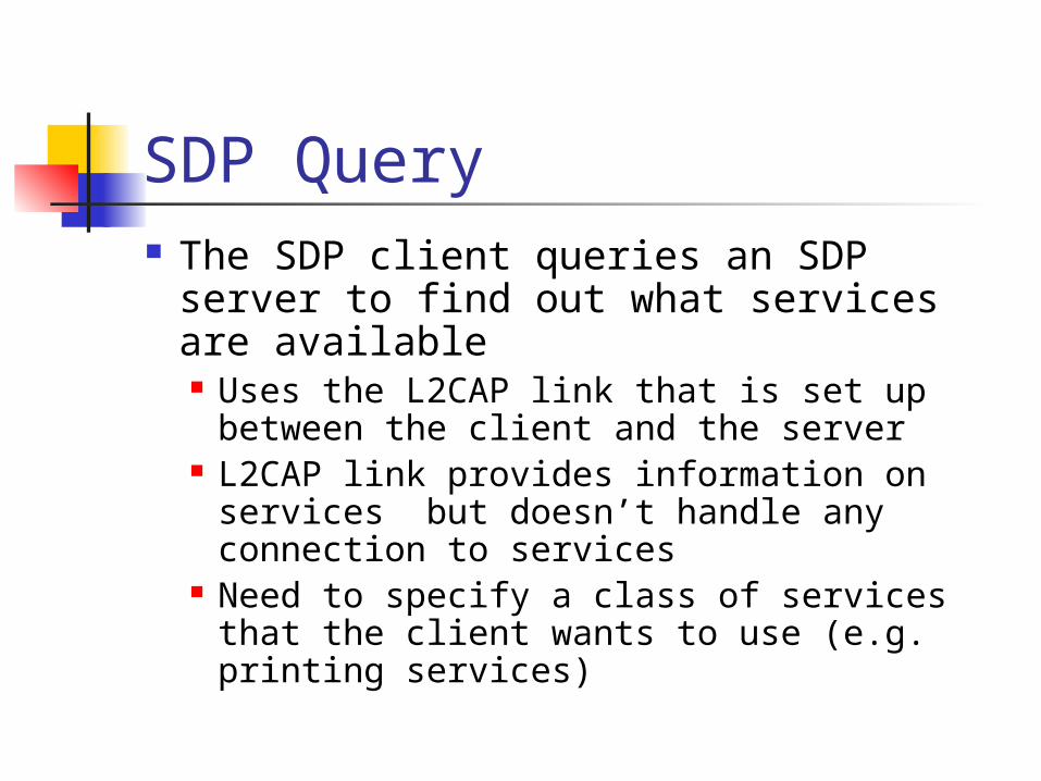
SDP Query The SDP client queries an SDP server
to find out what services are available Uses the L2CAP link that is set up
between the client and the server L2CAP link provides information on
services but doesn’t handle any connection to services
Need to specify a class of services that the client wants to use (e.g. printing services)
SDP Database SDP Database is a set of records that
describes the different services that the server can provide to another Bluetooth device
When the SDP server gets a query, it looks up the service that the client is requesting and returns information to the client on how to connect to the service
Using the Services The SDP client establishes a separate
(non-SDP) connection to use the service SDP connection is only used to determine
service availability The L2CAP connection uses to get
information for the service can be dropped (if no more services are needed) or retained (if the client still needs more services from the server)
Logical Link Control and Application Protocol (L2CAP) Performs 4 major functions
Managing the creation and termination of logical links for each connection through “channel” structures
Enforcing and defining QoS requirements Adapting Data, for each connection, between
application (APIs) and Bluetooth Baseband formats through Segmentation and Reassembly (SAR)
Performing Multiplexing to support multiple concurrent connections over a single common radio interface (multiple apps. using link between two devices simultaneously)
Segmentation/Reassembly Baseband packet size is limited
Can handle payload of 2745 bits L2CAP accepts packet size up to 64kb L2CAP segments large packets into
smaller baseband manageable packets
Smaller received baseband packets are reassembled coming back up the protocol stack
Quality of Service Applications may demand QoS on
specific parameters Peak bandwidth Latency Delay variation Token rate Token bucket size
L2CAP provides requested QoS if possible and notifies application if link can not support demands
Protocol Multiplexing Applications may access L2CAP through
different support protocols Service Discovery Protocol (SDP) RFCOMM Telephony Control Protocol Specification
(TCS) Baseband is not concerned with
operation protocols meaning L2CAP must distinguish between them
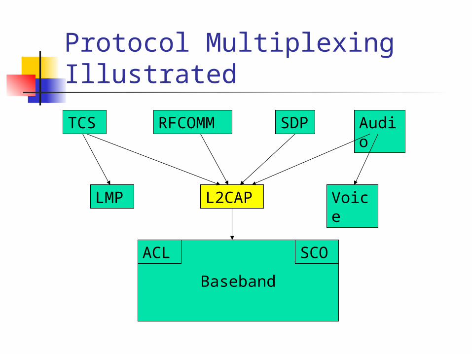
Baseband
Protocol Multiplexing Illustrated
LMP
Audio
L2CAP
SCOACL
Voice
TCS RFCOMM
SDP
Summary Advantages of Bluetooth
Low power consumption Low price on Bluetooth components Non line-of-sight
Disadvantages of Bluetooth Wireless LANs offer faster data rates and
larger communication ranges Possibility of interference on 2.4GHz
frequency band
Sources http://www.ericsson.com/bluetooth/bluetoothf/ http://www.ee.iitb.ernet.in/uma/~aman/bluetooth/ http://www.mprg.ee.vt.edu/tech_xfer/ppt/bt_tut.pdf http://www.xilinx.com/esp/bluetooth/tutorials/index.htm http://www.palowireless.com/infotooth/download.asp http://www.motorola.com/bluetooth/index.html Bluetooth: Connect without Cables by Jennifer Gray Discovering Bluetooth by Brent A. Miller