BlueSYSTEM basic eng WyBus - wylerag.com€¦ · page 3 of 84 content subject page 1 basics /...
84
WYLER AG Im Hölderli CH-8405 WINTERTHUR Switzerland Tel. 0041 (0) 52 233 66 66 Fax. 0041 (0) 52 233 20 53 Homepage: http://www.wylerag.com E-Mail: [email protected] Manual Blue Blue LEVEL BASIC - Blue METER BASIC Two BlueLEVEL BASIC with BlueMETER BASIC with wireless data transmission WyBUS-Technology
Transcript of BlueSYSTEM basic eng WyBus - wylerag.com€¦ · page 3 of 84 content subject page 1 basics /...

WYLER AGIm HölderliCH-8405 WINTERTHURSwitzerland
Tel. 0041 (0) 52 233 66 66Fax. 0041 (0) 52 233 20 53
Homepage: http://www.wylerag.comE-Mail: [email protected]
Manual
Blue BlueLEVEL BASIC - BlueMETER BASIC
Two BlueLEVEL BASIC with BlueMETER BASIC with wireless data transmission
WyBUS-Technology


page 3 of 84
CONTENT
SUBJECT PAGE
1 BASICS / INTRODUCTION 6 2 PREPARATION AND START-UP OF THE MEASURING INSTRUMENTS / BEFORE STARTING 7
2.1 INSERTING RESPECTIVELY REPLACEMENT OF BATTERIES IN BLUELEVEL BASIC AND/OR BLUEMETER BASIC 7
2.2 INITIAL START-UP OF THE INSTRUMETNS 8 2.3 CONNECTING THE INSTRUMENTS (BLUELEVEL BASIC AND BLUEMETER BASIC) 9 2.4 COMBINE A GROUP OF INSTRUMENTS USING THE FUNCTION "JOIN" 10
2.4.1 PROCEDURE "JOIN" WITH CABLE CONNECTION 10 2.4.2 PROCEDURE "LEAVE" 11 2.5 RESTART OF A MEASURING GROUP 11 3 DESCRIPTION AND FUNCTION OF THE BLUELEVEL BASIC WITH AND WITHOUT RADIO
MODULE 12
3.1 THE BLUELEVEL BASIC (OVERVIEW) 12 3.2 VIEW OF FUNCTIONAL KEYS BLUELEVEL BASIC 13
3.2.1 REAR VIEW 13 3.2.2 TOP VIEW OF THE BLUELEVEL BASIC WITH RADIO 13 2.3.2 TOP VIEW OF THE BLUELEVEL BASIC WITHOUT RADIO 14
4 DESCRIPTION OF THE BLUEMETER BASIC 15 4.1 STARTING THE BLUEMETER BASIC (AND THE INSTRUMENTS BLUELEVEL BASIC) 15 4.2 TYPICAL CONFIGURATIONS WITH BLUEMETER BASIC AND BLUELEVEL BASIC 16 4.3 FUNCTIONAL MENU WITH BLUEMETER BASIC USING THE FUNCTION KEY 17 4.4 FUNKTIONEN AM BLUEMETER BASIC ÜBER DIE FUNKTIONSTASTEN 18
ADDITIONAL FUNCTIONS OF THE BLUEMETER BASIC 27 4.5 TEACH-IN OF THE IR-TRIGGER (ZAPPER) TO THE BLUEMETER BASIC AND TO THE
BLUELEVEL BASIC) 28
4.6 OPERATING THE BLUEMETER BASIC 29 4.6.1 DESCRIPTION OF THE VARIOUS KEYS 29 4.6.2 DESCRIPTION OF VARIOUS DISPLAY FORMS ON THE BLUEMETER BASIC 32
APPENDIX 36
A BASICS AND GENERAL REMARKS ABOUT BLUESYSTEM BASIC AND INCLINATION MEASUREMENT 36
A1 INTRODUCTION TO THE BLUESYSTEM BASIC 36 A2 INSTRUMENT’S OVERVIEW THE INSTRUMENTS OF THE BLUESYSTEM BASIC - FAMILY IN
DETAIL 37
A3 MEASURING PROCEDURE / GENERAL HANDLING TYPICAL CONFIGURATIONS WITHOUT RADIO TRANSMISSION 39
TYPICAL CONFIGURATIONS WITHOUT RADIO TRANSMISSION 39 A4 BASIC SETUP OF THE INCLINATION MEASURING INSTRUEMNTS / PLUS - MINUS RULE 40 A5 ABSOLUTE MEASUREMENT / RELATIVE MEASUREMENT / DIFFERENTIAL MEASUREMENT 41 A6 GENERAL REMARKS ABOUT "ANGLES" AND "INCLINATION" 43 A7 HEIGHT RELATED TO THE STEP LENGTH 44 A8 ZERO SETTING BY REVERSAL MEASUREMENT (ABSOLUTE ZERO) 45 B APPLICATIONS 47
B1 MEASURING ABSOLUTE 47 B2 RELATIVE MEASUREMENT 47 B3 DIFFERENTIAL RESPECTIVELY REFERENCE MEASUREMENT USING AN ENGINEER SET 47 B4 ANGULAR MEASUREMENTS 50 B5 LINES AND FLATNESS MEASUREMENT (MANUAL PROCEDURE) 51 C WYLER SOFTWARE LEVELSOFT PRO 52

page 4 of 84
D SOFTWARE FOR THE DEFINITION OF MACHINE TOOL GEOMETRY MACHINE TOOL INSPECTION SOFTWARE MT-SOFT
54
E EXAMPLE USING THE HYPER TERMINAL OF WINDOWS OR WINDOWS TERMINAL PROGRAM 55 F WYBUS COMPATIBLE INSTRUMENTS 57
F1 CONNECTION THROUGH A SHORT CABLE 57 F2 CONNECTION THROUGH A LONG 57 G SPECIAL FUNCTIONS 58
G1 RESET TO FACTORY PRE-SETTINGS 58 G2 FIRMWARE VERSION 58 H TECHNICAL DATA BLUESYSTEM BASIC 59
H1 TECHNICAL DATA OF THE RADIO MODULES BLUESYSTEM BASIC (OPTIONAL) 59 H2 TECHNICAL DATA BLUELEVEL BASIC 59 H3 TECHNICAL DATA OF THE BLUEMETER BASIC 60 H4 PIN-DEFINITION FOR BLUELEVEL + BLUEMETER,
BLUELEVEL + BLUEMETER BASIC AND BLUETC 60
I SERVICE AND REPAIR 61 I1 REPAIR OF MEASURING INSTRUMENTS AND DISPLAY UNITS 61 I2 SERVICE- AND MAINTENANCE CONTRACTS 62 J STORAGE OF THE INSTRUMENTS / CARE AND HANDLING OF THE BATTERIES 63
J1 STORAGE OF THE INSTRUMENTS 63 J2 CARE AND HANDLING OF THE BATTERIES 63 K ACCREDITATION BLUETOOTH™ WIRELESS TECHNOLOGY FOR BLUESYSTEM 64
K1 MANUFACTURER DECLARATION OF CONFORMITY (DOC) 64 K2 BLUETOOTH EQUIPMENT 65 K3 FCC COMPLIANCE 65 K4 COUNTRY SPECIFIC INFORMATION FOR BLUETOOTH RADIO LINK 66 L FLOWCHARTS (BLUEMETER BASIC ONLY) 68
L1 POWER UP (BLUEMETER BASIC ONLY) 68 L2 SAMPLING (BLUEMETER BASIC ONLY) 69 L3 SENSOR (BLUEMETER BASIC ONLY) 70 L4 REFRESH (BLUEMETER BASIC ONLY) 71 L5 RELATIVES ZERO (BLUEMETER BASIC ONLY) 72 L6 EINHEITEN / UNIT (BLUEMETER BASIC ONLY) 73 L7 ABSOLUTES ZERO / ABS ZERO (BLUEMETER BASIC ONLY) 74 L8 FILTER (BLUEMETER BASIC ONLY) 75 L9 FUNK / RADIO (BLUEMETER BASIC ONLY) 76
L10 JOIN (BLUEMETER BASIC ONLY) 77 L11 LEAVE (BLUEMETER BASIC ONLY) 78 L12 HOLD (BLUEMETER BASIC ONLY) 79 M INDEX / KEYWORDS 80

page 5 of 84
Modifications:
Date Modified by Description of modifications
5.2.2008 HEH New with wireless data transmission 01.05.2009 HEH / TRA New with WyBus technology

page 6 of 84
The following ADDITIONAL MANUALS may be downloaded from http://www.wylerag.com:
• LEVELSOFT PRO, the software for measuring flatness and inclination with WYLER inclination measuring instruments
• MT-SOFT, that gives the possibility to measure individual elements of machine tools with standard inclination measuring instruments. The measured results can be saved and at a later stage used for comparison and put together to receive a thorough result of the over all accuracy of the machine tool.
• COMPENDIUM, the guide to our products, technology and to a variety of applications.
• Description of the interface RS485 If for any reason it is not possible to download the respective data we will gladly supply against a nominal charge a CD "ALL-IN-ONE" with all the manuals in different languages included 1. BASICS / INTRODUCTION The new BlueSYSTEM BASIC series has been developed as a basic model to the well known and well proven measuring instruments of the BlueSYSTEM family with wireless data transmission. Compared to the existing systems with wireless data transmission the BlueSYSTEM BASIC series has an excellent price/performance ratio and is easier to operate. The BlueSYSTEM BASIC is available with wireless data transmission or cable transmission. It is however possible to upgrade the system without wireless data transmission at a later stage by WYLER to use BLUETOOTH™ wireless technology. As its predecessor this newest generation of high precision electronic inclination measuring instruments is specifically suitable for the precision measurement of smallest angles. Applications are therefore in particular the measurement of flatness of surface plates or the measurement of the geometry of machine tools. The sensor itself, the heart of every precision measuring instrument, has been further developed as well, to allow precise measurements even under critical environmental conditions. The new measuring instruments of the BlueSYSTEM BASIC family can not be used as stand-alone instruments as they do not feature an integrated display. The instrument must be combined with an external display unit (BlueMETER BASIC) in a set. A set of instruments, also called ENGINEER SET, normally consists of one or two BlueLEVEL BASIC and one BlueMETER BASIC, forming the ideal tool for measuring flatness and machines under work shop conditions. Furthermore the ENGINEER SET can be used for any levelling task or analysis of rotations.

page 7 of 84
2 PREPARATION AND START-UP OF THE MEASURING INSTRUMENTS BEFORE STARTING 2.1 INSERTING RESPECTIVELY REPLACEMENT OF BATTERIES IN BLUELEVEL BASIC AND/OR BLUEMETER BASIC 2.1.1 EXCHANGE OF BATTERIES IN THE BLUEMETER BASIC The batteries are not installed in the new instruments they are delivered separately. It is recommended to remove the batteries when transporting the instruments. 3 pieces 1.5V, Size “C” ALKALINE
2.1.2 INSERTION RESPECTIVELY EXCHANGE OF THE BATTERIES IN THE BLUELEVEL BASIC The lowest voltage is 1,7 Volt. After a further voltage drop the red LED "low Power" on top of the handle will start
blinking. The batteries should then be replaced.
2 pieces 1.5V, Size “C” ALKALINE

page 8 of 84
2.2 INITIAL START-UP OF THE INSTRUMETNS General remarks for instruments with wireless data transmission:
• The operation "Combine a group of Instruments" described in chapter 2.4 has already been done at WYLER's when the instruments are delivered.
• If a configuration is shut off, e.g. after completion of a measurement, the group-setup remains saved. When started again, the communication will be re-activated immediately, i.e. no new grouping will be required.
• If the group of instruments is extended or amended, e.g. by adding or exchanging an instrument, the new instrument must be joined to the group as described in chapter 2.4 "Combine a group of instruments"
First time start-up of a measuring group (BlueLEVEL BASIC and BlueMETER BASIC) with radio transmission (wireless transmission of the measuring data)
1. Remove the instruments carefully from the transport and storage case and insert the batteries 2. For groups of instruments with wireless data transmission (BlueLEVEL BASIC and BlueMETER BASIC)
the instruments are delivered in a set-up enabling them to recognise each other after the start-up 3. Place the instruments on a clean horizontally aligned surface. Switch on the instruments (BlueLEVEL BASIC
and BlueMETER BASIC). Press the two keys <ON/OFF> and <ON> on either side of the BlueLEVEL BASIC simultaneously respectively the key <ON/MODE> on the BlueMETER BASIC until all 5 LEDs are on. When you release the keys "SYSTEM TEST" will appear on the display. If the two keys <ON/OFF> and <ON> of the BlueLEVEL respectively the key <ON/MODE> of the BlueMETER BASIC are pressed longer than 10 seconds when starting the instrument, all the LEDs start blinking and thus the automatic shut-off system is deactivated. In the standard mode the instrument is shut-off automatically after 60 minutes
4. The instruments are now communicating and after a few seconds the measured values will appear on the display of the BlueMETER BASIC. The battery power should be checked (see below)
5. The actual measurement may now be started First time start-up of a measuring group (BlueLEVEL BASIC and BlueMETER BASIC) without radio transmission (transmission of the measuring data by cables)
1. Remove the instruments carefully from the transport and storage case and insert the batteries 2. Place the measuring instruments on a clean horizontally aligned surface. Connect the instruments
(BlueLEVEL BASIC and BlueMETER BASIC) with the cable(s) supplied 3. Switch on the instruments. Press the two keys <ON/OFF> and <ON> on either side of the BlueLEVEL BASIC
simultaneously respectively the key <ON/MODE> on the BlueMETER BASIC until all 5 LEDs are ON. When you release the key(s) "SYSTEM TEST" will appear on the display If the two keys <ON/OFF> and <ON> of the BlueLEVEL respectively the key <ON/MODE> of the BlueMETER BASIC are pressed longer than 10 seconds when starting the instrument, all the LEDs start blinking and thus the automatic shut-off system is deactivated. In the standard mode the instrument is shut-off automatically after 60 minutes
4. The instruments are ready without delay and after a few seconds the measured values will appear on the display of the BlueMETER BASIC. The battery power should be checked (see below).
5. The actual measurement may now be started Remarks concerning the battery power:
BlueMETER BASIC
Display of the actual battery power (Example: 3,6 V)
page 9 of 84
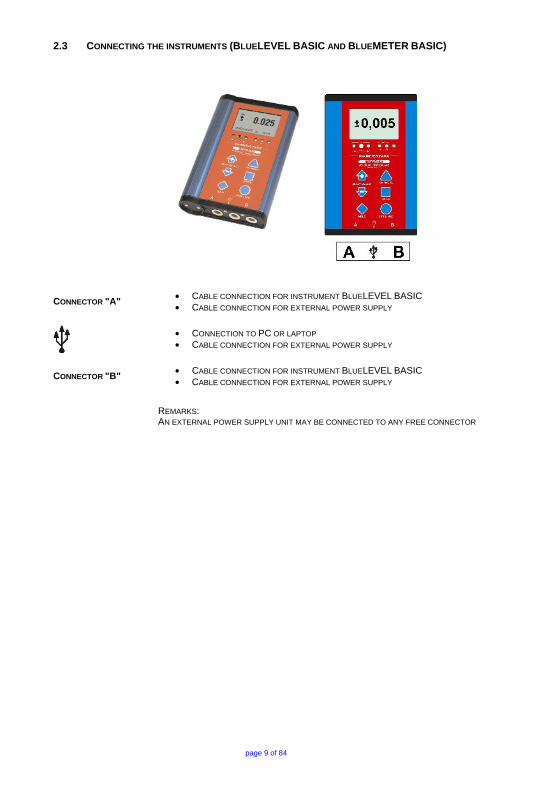
2.3 CONNECTING THE INSTRUMENTS (BLUELEVEL BASIC AND BLUEMETER BASIC)
CONNECTOR "A" • CABLE CONNECTION FOR INSTRUMENT BLUELEVEL BASIC • CABLE CONNECTION FOR EXTERNAL POWER SUPPLY
• CONNECTION TO PC OR LAPTOP • CABLE CONNECTION FOR EXTERNAL POWER SUPPLY
CONNECTOR "B" • CABLE CONNECTION FOR INSTRUMENT BLUELEVEL BASIC • CABLE CONNECTION FOR EXTERNAL POWER SUPPLY
REMARKS: AN EXTERNAL POWER SUPPLY UNIT MAY BE CONNECTED TO ANY FREE CONNECTOR
page 10 of 84
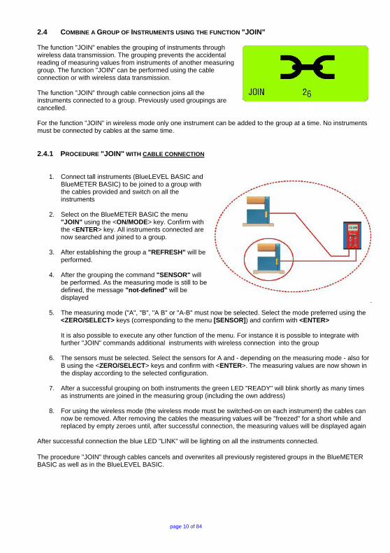
2.4 COMBINE A GROUP OF INSTRUMENTS USING THE FUNCTION "JOIN" The function "JOIN" enables the grouping of instruments through wireless data transmission. The grouping prevents the accidental reading of measuring values from instruments of another measuring group. The function "JOIN" can be performed using the cable connection or with wireless data transmission. The function "JOIN" through cable connection joins all the instruments connected to a group. Previously used groupings are cancelled. For the function "JOIN" in wireless mode only one instrument can be added to the group at a time. No instruments must be connected by cables at the same time. 2.4.1 PROCEDURE "JOIN" WITH CABLE CONNECTION
1. Connect tall instruments (BlueLEVEL BASIC and BlueMETER BASIC) to be joined to a group with the cables provided and switch on all the instruments
2. Select on the BlueMETER BASIC the menu "JOIN" using the <ON/MODE> key. Confirm with the <ENTER> key. All instruments connected are now searched and joined to a group.
3. After establishing the group a "REFRESH" will be performed.
4. After the grouping the command "SENSOR" will be performed. As the measuring mode is still to be defined, the message "not-defined" will be displayed
5. The measuring mode ("A", "B", "A B" or "A-B" must now be selected. Select the mode preferred using the <ZERO/SELECT> keys (corresponding to the menu [SENSOR]) and confirm with <ENTER> It is also possible to execute any other function of the menu. For instance it is possible to integrate with further "JOIN" commands additional instruments with wireless connection into the group
6. The sensors must be selected. Select the sensors for A and - depending on the measuring mode - also for B using the <ZERO/SELECT> keys and confirm with <ENTER>. The measuring values are now shown in the display according to the selected configuration.
7. After a successful grouping on both instruments the green LED "READY" will blink shortly as many times as instruments are joined in the measuring group (including the own address)
8. For using the wireless mode (the wireless mode must be switched-on on each instrument) the cables can now be removed. After removing the cables the measuring values will be "freezed" for a short while and replaced by empty zeroes until, after successful connection, the measuring values will be displayed again
After successful connection the blue LED "LINK" will be lighting on all the instruments connected. The procedure "JOIN" through cables cancels and overwrites all previously registered groups in the BlueMETER BASIC as well as in the BlueLEVEL BASIC.

page 11 of 84
2.4.2 PROCEDURE "LEAVE" Using the function "LEAVE" unleashes an existing measuring group.
1. Press the <ON/MODE> button on the BlueMETER BASIC repeatedly until the menu [LEAVE] appears on the display. Confirm with <ENTER>.
2. During the log-off the blue LED under "LINK" is lit continuously, the green LED "READY" is blinking or does not shine any more.
3. After successful completion the green LED is blinking for approx. 1 second. This erminates the process.
2.5 RESTART OF A MEASURING GROUP After a measuring group has been stopped e.g. after the termination of a measurement, the group of instruments remains intact. After the restart the communication is automatically activated and the communication is started. The process JOIN must not be repeated.
page 12 of 84
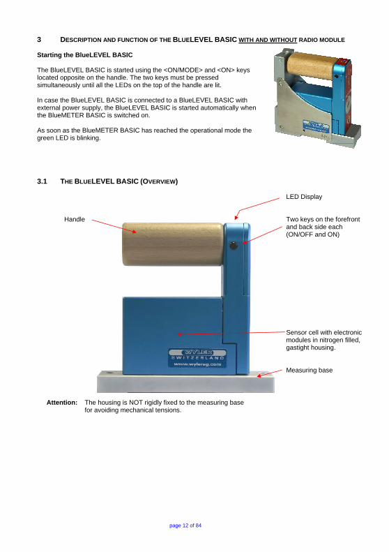
3 DESCRIPTION AND FUNCTION OF THE BLUELEVEL BASIC WITH AND WITHOUT RADIO MODULE Starting the BlueLEVEL BASIC The BlueLEVEL BASIC is started using the <ON/MODE> and <ON> keys located opposite on the handle. The two keys must be pressed simultaneously until all the LEDs on the top of the handle are lit. In case the BlueLEVEL BASIC is connected to a BlueLEVEL BASIC with external power supply, the BlueLEVEL BASIC is started automatically when the BlueMETER BASIC is switched on. As soon as the BlueMETER BASIC has reached the operational mode the green LED is blinking.
3.1 THE BLUELEVEL BASIC (OVERVIEW) LED Display
Handle
Two keys on the forefront and back side each (ON/OFF and ON) Sensor cell with electronic modules in nitrogen filled, gastight housing. Measuring base
Attention: The housing is NOT rigidly fixed to the measuring base for avoiding mechanical tensions.
page 13 of 84
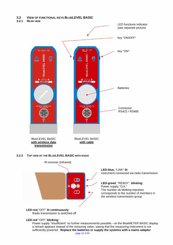
3.2 VIEW OF FUNCTIONAL KEYS BLUELEVEL BASIC 3.2.1 REAR VIEW LED functions indicator
(see separate picture)
BlueLEVEL BASIC with wireless data
transmission
BlueLEVEL BASIC with cable
key "ON/OFF" key "ON" Batteries Connector RS422 / RS485
3.2.2 TOP VIEW OF THE BLUELEVEL BASIC WITH RADIO
IR-receiver (infrared)
LED-blue, “LINK“ lit: instrument connected via radio transmission LED-greed, "READY", blinking: Power supply "O.K." The number ob blinking impulses corresponds to the number of members in the wireless transmission group
LED-red,"OFF" lit continuously: Radio transmission is switched off
LED-red "OFF" blinking:
Power supply "insufficient" no further measurements possible.- on the BlueMETER BASIC display a remark appears instead of the mesuring value, saying that the measuring instrument is not sufficiently powered. Replace the batteries or supply the systems with a mains adapter

page 14 of 84
3.2.3 TOP VIEW OF THE BLUELEVEL BASIC WITHOUT RADIO
IR-receiver (infrared)
LED-blue, “AUX“ not used LED-green, "OK", lit continuously: Power supply "O.K."
LED-red blinking:
Power supply "insufficient" no further measurements possible.- on the BlueMETER BASIC display a remark appears instead of the mesuring value, saying that the measuring instrument is not sufficiently powered. Replace the batteries or supply the systems with a mains adapter

page 15 of 84
4 DESCRIPTION OF THE BLUEMETER BASIC The BlueMETER BASIC is an intelligent digital display unit developed by WYLER AG for the inclination measuring instrument BlueLEVEL BASIC. Besides the excellent measuring accuracy the BlueLEVEL instruments supply a fully digital signal for transmitting these over long distances without any loss of quality. The BlueMETER BASIC is
- a display unit - an interface between instrument and PC/Laptop On the BlueMETER BASIC various parameters may be set or changed, such as:
- Measuring units - Address of instruments/sensors, port definition (Port) - Filter-settings
- Relative base length etc. It is possible to send measured data via a RS 232 port to a printer, a PC/Laptop or the WYLER software LEVELSOFT PRO, MT-SOFT and LabEXCEL
• Compact and pleasant design in aluminium housing and state of the art technology.
• Wireless data transmission based on the internationally approved Bluetooth™-standard
• Large and well readable LCD display
• Display showing the automatically recognized instruments connected
• Powered by standard 1.5 V batteries type “C”
• In compliance with CE regulations and all applicable EMC regulations 4.1 STARTING THE BLUEMETER BASIC (AND THE INSTRUMENTS BLUELEVEL BASIC) Please read the manual carefully before working with the BlueMETER BASIC and the BlueLEVEL BASIC for the first time. Switching the BlueMETER BASIC on Press the key <ON/MODE> until all 5 LEDs are ON, release the key and "SYSTEM TEST" will appear in the display. After the start-up you will see the actual measuring value of the instruments connected in the last saved measuring configuration and measuring unit. Using the battery, mode the instrument is automatically shut off after 60 minutes. If the key <ON/MODE> is pressed for more than 10 seconds when starting the BlueMETER BASIC all the LEDs start blinking and the automatic shut-off is deactivated.

page 16 of 84
4.2 TYPICAL CONFIGURATIONS WITH BLUEMETER BASIC AND BLUELEVEL BASIC Configurations using BlueLEVEL BASIC instruments and BlueMETER BASIC
Data transmission via cables
Configurations with wireless data transmission
Configurations with data transmission via cables and with connection to a PC/Laptop
Configurations with wireless data transmission and with connection to a PC/Laptop
Remarks: Systems equipped with wireless data transmission can alternatively be used with cable connection. The radio module will be deactivated.

page 17 of 84
4.3 Overview of the BLUEMETER BASIC
Large LCD display with actual measured value, instrument’s address and measuring unit
LED showing activities Status power supply and transmission and infrared contact. Panel with functional keys Aluminium housing anodized
Battery compartment Connectors for instruments/sensors/power supply and output to PC/Laptop
page 18 of 84
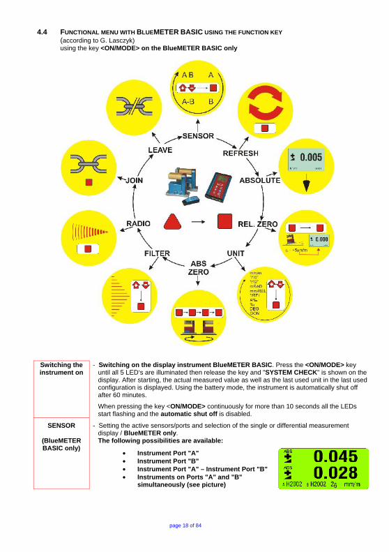
4.4 FUNCTIONAL MENU WITH BLUEMETER BASIC USING THE FUNCTION KEY (according to G. Lasczyk) using the key <ON/MODE> on the BlueMETER BASIC only
Switching the instrument on
- Switching on the display instrument BlueMETER BASIC. Press the <ON/MODE> key until all 5 LED‘s are illuminated then release the key and "SYSTEM CHECK" is shown on the display. After starting, the actual measured value as well as the last used unit in the last used configuration is displayed. Using the battery mode, the instrument is automatically shut off after 60 minutes.
When pressing the key <ON/MODE> continuously for more than 10 seconds all the LEDs start flashing and the automatic shut off is disabled.
SENSOR
(BlueMETER BASIC only)
- Setting the active sensors/ports and selection of the single or differential measurement display / BlueMETER only. The following possibilities are available:
• Instrument Port "A" • Instrument Port "B" • Instrument Port "A" – Instrument Port "B" • Instruments on Ports "A" and "B"
simultaneously (see picture)
page 19 of 84
cont.
SENSOR
(BlueMETER BASIC only)
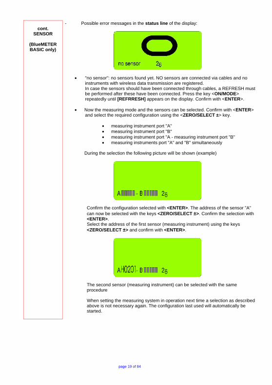
- Possible error messages in the status line of the display:
• "no sensor": no sensors found yet. NO sensors are connected via cables and no instruments with wireless data transmission are registered. In case the sensors should have been connected through cables, a REFRESH must be performed after these have been connected. Press the key <ON/MODE> repeatedly until [REFRRESH] appears on the display. Confirm with <ENTER>.
• Now the measuring mode and the sensors can be selected. Confirm with <ENTER> and select the required configuration using the <ZERO/SELECT ±> key.
• measuring instrument port "A" • measuring instrument port "B" • measuring instrument port "A - measuring instrument port "B" • measuring instruments port "A" and "B" simultaneously
During the selection the following picture will be shown (example)
Confirm the configuration selected with <ENTER>. The address of the sensor "A" can now be selected with the keys <ZERO/SELECT ±>. Confirm the selection with <ENTER>. Select the address of the first sensor (measuring instrument) using the keys <ZERO/SELECT ±> and confirm with <ENTER>.
The second sensor (measuring instrument) can be selected with the same procedure When setting the measuring system in operation next time a selection as described above is not necessary again. The configuration last used will automatically be started.

page 20 of 84
cont.
SENSOR
(BlueMETER BASIC only)
- Possible error messages in the display:
• When starting the system a cross between to arrows appears (picture above) • If a cross between two arrows appears this is a hint that the sensor is listed in the
configuration of instruments but cannot be detected due to one of the following reasons: o The measuring instrument is not switched on o The distance between the BlueMETER BASIC and the Blue LEVEL BASIC is
to long o The wireless communication element on the measuring instrument is not
switched on
REFRESH
(BlueMETER BASIC only)
Starts the search for instruments connected and registers them in the internal list of instruments. Instruments not connected any more are marked in the list of instruments as not present. To make a later search easier these remain, however, in the list. The function REFRESH must be performed when new instruments have been connected. After the REFRESH the instrument automatically executes the function SENSOR and waits for the selection of a sensor. If BlueLEVEL BASIC or BlueTC instruments, which have never before been linked to this BlueMETER, should be used, these must be integrated step by step. After each new instrument connected to a set of cables the function REFRESH must be performed again. For BlueMETER only
ABSOLUTE
(BlueMETER BASIC only)
Standard measuring mode, absolute measured value (Zero-offset considered). Provided that a reversal measurement has been performed before, the instrument displays the actual deviation from the absolutely horizontal plane.

page 21 of 84
REL.ZERO
(BlueMETER BASIC only)
With one instrument (Display on the BlueMETER BASIC only)
Relative measured value (In the relative mode a "ZERO-OFFSET" determined e.g. by reversal measurement is superimposed by the value "REL ZERO OFFSET") Use the key <ON/MODE> select the menu [REL.ZERO] and confirm with <ENTER>. First the following picture is shown in the display of the BlueMETER BASIC.
Use <ENTER> or the IR-zapper for confirming the choice. The actual values are collected and constantly displayed.
When the values have stabilized the relative ZERO can be confirmed with <ENTER> or with the IR-zapper.
On the display the value “0.000” is seen. This is now the relative value considering the offset. This value is used for all additional measurements as reference.

page 22 of 84
Cont.
REL.ZERO
(BlueMETER BASIC only)
Option / Manual setup Use the key <ON/MODE> select [REL.ZERO] and confirm with <ENTER>. First the following picture is shown in the display of the BlueMETER BASIC
Use <ON/MODE> for cancelling the procedure The following picture is seen. It shows an earlier value for a ZERO OFFSET.
This value may now be changed manually with the keys <ZERO/SELECT ±> and then confirmed with <ENTER>. On the display the value is seen. This is now the relative value considering the offset. This value is used for all additional measurements as reference. E.g.
Two instruments connected, differential measurement Instrument "A" minus instrument "B"
Use the key <ON/MODE> select [REL.ZERO] and confirm with <ENTER>. First the following picture is shown in the display

page 23 of 84
REL.ZERO
(BlueMETER BASIC only)
Use <ENTER> or the IR-zapper for confirming the choice. The actual values are collected and constantly displayed.
When the values have stabilized the relative ZERO can be confirmed with <ENTER> or with the IR-zapper.
On the display of the BlueMETER BASIC the value "0.000" is seen. This is now the relative value considering the offset. This value is used for all additional measurements as reference.

page 24 of 84
UNIT
(BlueMETER BASIC only)
Setting the measuring unit. The desired measuring unit can be selected by repeatedly pressing the key <ON/MODE> until the selection pointer is below the function UNIT. Confirm with the <ENTER> key. The following measuring units can be chosen at the BlueMETER BASIC:
XXX.XXX XX.XXXX XXXX.XX XXX.XXX XX.XXXX XX.XXXX XXXX.XX XXX.XXX XXXX.XX XXX.XXX XX.XXXX XXXX.XX XXXX.XX XXX.XXX XXXX°XX' XXXX'XX" XXXXXX" XXXXX.X" XX°XX’XX’’
GON GON
mm/m mm/m "/10" "/12" mRad mRad
mm/REL mm/REL
"/REL A %o %o
DEG DEG DEG DEG DEG DEG
New degree, 3 decimals New degree, 4 decimals mm per m / 2 decimals mm per m / 3 decimals Inch per 10 Inch / 4 decimals Inch per 12 Inch / 4 decimals Milliradian / 2 decimals Milliradian / 3 decimals mm per relative base / 2 decimals mm per relative base / 3 decimals Inch per relative base / 4 decimals Artillerie-permille Permille Degree / 3 decimals Degree / Minutes Minutes / Seconds Seconds Seconds / 1 decimal Degree / Minutes / Seconds
CHANGE RELATIVE BASE / SAVE SET-UP A mode, displaying inclination by the height in mm [mm/REL] / inch ["/REL] at the end of a straight line with the length previously set, is included in the BlueMETER BASIC. Factory default settings for base length are: 1000 mm or 10.000 inch.
After selecting the unit [mm/REL] or ["/REL] the last defined relative base length is displayed. If no relative base length has been selected previously a standard base length of either1000 mm or 10.000 inches is shown. This relative base length can be changed as follows:
• The displayed values may be changed by using the key <ZERO/SELECT ±>, the change begins with the last (lowest) digit
• Using the key <ON/MODE> the next digit to be changed is selected • At the end the changes will be saved by using the key <ENTER>
The displayed value is from now on the measured height related to the relative base length

page 25 of 84
ABS.ZERO
(BlueMETER BASIC only)
Setting of absolute ZERO with a reversal measurement. Using the reversal measurement is a simple way to determine the exact ZERO OFFSET of the instrument as well as the exact inclination of the surface where the instrument is placed.
• Slide the instrument onto a flat, horizontally levelled surface (e.g. engineer's surface plate).
• The position of the instrument is to be marked on the surface.
• Use the key <ON/MODE> to get to the menu point [ABS.ZERO] and confirm with <ENTER> On the BlueMETER BASIC the following display is seen:
• Use the zapper or confirm with <ENTER>. On the display the progress of the collected values are visible in graphic form.
When the curve is getting a straight line confirm the first value with the zapper or with <ENTER>
• After the first reading the following display is seen:
This display means the first reading was successful. The instrument must be turned 180 degrees without lifting and slid exactly onto the previously marked position
• Use the zapper or confirm with <ENTER>. On the display the progress of the collected values are again visible in graphic form.
page 26 of 84
Cont.
ABS.ZERO
(BlueMETER BASIC only)
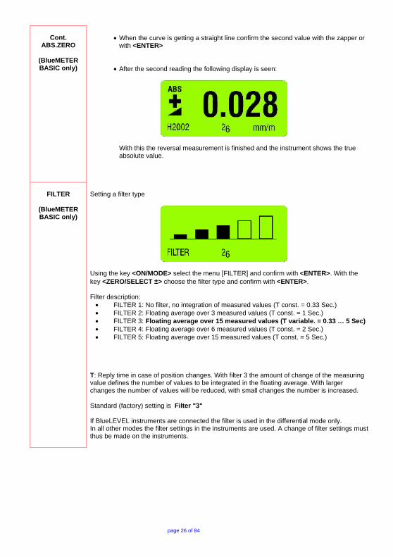
• When the curve is getting a straight line confirm the second value with the zapper or
with <ENTER>
• After the second reading the following display is seen:
With this the reversal measurement is finished and the instrument shows the true absolute value.
FILTER
(BlueMETER BASIC only)
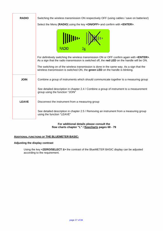
Setting a filter type
Using the key <ON/MODE> select the menu [FILTER] and confirm with <ENTER>. With the key <ZERO/SELECT ±> choose the filter type and confirm with <ENTER>. Filter description:
• FILTER 1: No filter, no integration of measured values (T const. = 0.33 Sec.) • FILTER 2: Floating average over 3 measured values (T const. = 1 Sec.) • FILTER 3: Floating average over 15 measured values (T variable. = 0.33 … 5 Sec) • FILTER 4: Floating average over 6 measured values (T const. = 2 Sec.) • FILTER 5: Floating average over 15 measured values (T const. = 5 Sec.)
T: Reply time in case of position changes. With filter 3 the amount of change of the measuring value defines the number of values to be integrated in the floating average. With larger changes the number of values will be reduced, with small changes the number is increased. Standard (factory) setting is Filter "3" If BlueLEVEL instruments are connected the filter is used in the differential mode only. In all other modes the filter settings in the instruments are used. A change of filter settings must thus be made on the instruments.
page 27 of 84
RADIO Switching the wireless transmission ON respectively OFF (using cables / save on batteries!) Select the Menu [RADIO] using the key <ON/OFF> and confirm with <ENTER>.
For definitively switching the wireless transmission ON or OFF confirm again with <ENTER>. As a sign that the radio transmission is switched off, the red LED on the handle will be ON. The switching on of the wireless transmission is done in the same way. As a sign that the wireless transmission is switched ON, the green LED on the handle is blinking.
JOIN
Combine a group of instruments which should communicate together to a measuring group See detailed description in chapter 2.4 / Combine a group of instrument to a measurement group using the function "JOIN"
LEAVE
Disconnect the instrument from a measuring group See detailed description in chapter 2.5 / Removing an instrument from a measuring group using the function "LEAVE"
For additional details please consult the
flow charts chapter "L" / flowcharts pages 68 - 79 ADDITIONAL FUNCTIONS OF THE BLUEMETER BASIC: Adjusting the display contrast
Using the key <ZERO/SELECT ±> the contrast of the BlueMETER BASIC display can be adjusted according to the requirement.

page 28 of 84
4.5 TEACH-IN of the IR-trigger (Zapper) to the BlueMETER BASIC and to the BlueLEVEL BASIC) In order to eliminate interference of the zapper signals when several measuring groups are active in the triggering range the IR trigger can be assigned to a specific measuring group by applying the function TEACH-IN Procedure TEACH-IN:
• The measuring or display instrument must be started • Keep the key <ON> on the measuring instrument (BlueLEVEL BASIC)
or the key <ZERO/SELECT> on the display instrument (BlueMETER BASIC) pressed
• Point the trigger (IR-zapper) in direction of the measuring or display instrument • Press the actuator key on the IR Zapper until both red IR LEDs are lighting up
When the instruments are dispatched this procedure is already factory set standard.

page 29 of 84
4.6 OPERATING THE BLUEMETER BASIC
4.6.1 DESCRIPTION OF THE VARIOUS KEYS
<ON/MODE> - Key
Function - 1 –
Starting the BlueMETER BASIC. Press the <ON/MODE> key until all the 5 LED‘s are illuminated and on the display it is shown "SYSTEM TEST". After starting the actual measured value as well as the last used unit is displayed. E.g.: Actual value and unit set actual leading sign and showing the measurement mode (in the example: ABS = ABSOLUTE mode)
Unit in [mm/m], resp. [µm/m] or in [Arcsec]
Serial number of instrument used as identification.
Actual battery power
Deactivating the automatic instrument shut off of the BlueMETER BASIC:
When pressing the <ON/MODE> key at the starting of the instrument longer than 10 seconds all LED’s start blinking and the automatic shut off is deactivated. Exception: When the BlueMETER BASIC is connected to an external power supply the instrument never shuts off automatically.
Function - 2 - The key <ON/MODE> is used for handling the internal menu. When pressing several times other menu points are displayed.
Function - 3 - For shutting off the BlueMETER BASIC the key <ON/MODE> must be pressed continuously until all 5 LED’s are on and the instrument’s display is completely off. When the key <ON/MODE> is continuously pressed for longer than 15 seconds, a date and a 4-digit number is displayed. This number shows the software version loaded in the instrument.
Function - 4 -
Setting the displayed values (memory values) of the functions "REL.ZERO" and "ABS.ZERO" to ZERO. When a value is displayed in this function the value can be set to ZERO by pressing the key <ON/MODE> or the value can be altered step by step by using the key <ZERO/SELECT ±>. The action must be confirmed by using <ENTER>.

page 30 of 84
<ENTER> – Key
Function – 1 –
The key <ENTER> is used for saving data or for confirming taken actions.
Function - 2 -
In connection with the software LEVELSOFT PRO and MT-SOFT the key is used for collecting the actual measured value.
Function – 3
The key <ENTER> is used for turning on resp. turning off the backlight in the display
<SEND/ESC>- Key
Function - 1 -
Using the key <SEND/ESC> will send the displayed value to a port of a connected PC, or Laptop. It is recommended to use the infrared zapper instead of the <SEND/ESC> key. OUT-port data format
MeasuringMode_A [sss xxxxxx sn.nnnnnn<cr>] MeasuringMode_B [sss xxxxxx sn.nnnnnn<cr>] MeasuringMode_A_minusB [sss xxxxxx - xxxxxx sn.nnnnnn<cr>] MeasuringMode_A_B [sss xxxxxx sn.nnnnnn xxxxxx sn.nnnnnn<cr>]
sss = 0 .. 255 - Sequence number xxxxxx = Sensor Serial Number and Type
H4001B BlueLEVEL or BlueLEVEL BASIC H4001C +CLINO PLUS+ H4001M MINILEVEL NT H4001Z ZEROTRONIC Sensor H4001x ZEROMATIC 2/1 X - Axis H4001y ZEROMATIC 2/1 Y - Axis H4001X ZEROMATIC 2/2 X - Axis H4001Y ZEROMATIC 2/2 Y - Axis sn.nnnnnn = +9.999999 - Positive Overrange -9.999999 - Negative Overrange Measured value - Angle in rad e.g. +0.226349
Data transmission format: asynchron, 7Bit, 2 Stopbits, no parity
Function - 2 -
Delete the "HOLD" function and return to the mode MEASURE.
Function - 3 -
Cancel the functions of the various menus

page 31 of 84
<ZERO/SELECT ±> - Keys
Function - 1 -
The keys <ZERO/SELECT ±> are used for selecting different settings, such as:
- Measuring unit - Ports ( "A" / "B" / "A - B" / "A B") - Relative base settings - Set "Zero-Offset" - Set "REL Zero-Offset" etc.
Function - 2 - Adjustment of display contrast
<HOLD> - Key
Function - 1 -
With the <HOLD> key a measured value may be "frozen". After pressing the key <HOLD> without further action by the user, the measured value is collected during 15-17 seconds and then displayed. When the conditions are stable this data collection may be reduced by earlier pressing the key <ENTER>. The display shows "on hold". This “frozen” value will be displayed until - by pressing the key <SEND/ESC> - the BlueMETER BASIC will return to the measuring mode.
Function - 2 -
When using the mode "REL.ZERO" and "ABS.ZERO" the actual measuring value can be accepted by pressing the <HOLD> key.
page 32 of 84
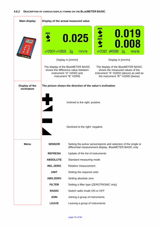
4.6.2 DESCRIPTION OF VARIOUS DISPLAY FORMS ON THE BLUEMETER BASIC
Main display
Display of the actual measured value
Display in [mm/m]
The display of the BlueMETER BASIC shows the difference value between
instrument "A" H2002 and instrument "B" H2005
Display in [mm/m]
The display of the BlueMETER BASIC shows the measured values of the
instrument "A" H2002 (above) as well as the instrument "B"“ H2005 (below)
Display of the inclination
The picture shows the direction of the value’s inclination
Inclined to the right: positive
Declined to the right: negative
Menu
SENSOR
REFRESH
ABSOLUTE
REL.ZERO
UNIT
ABS.ZERO
FILTER
RADIO
JOIN
LEAVE
Setting the active sensors/ports and selection of the single or differential measurement display. BlueMETER BASIC only Update of the list of instruments Standard measuring mode Relative measurement Setting the required units Setting absolute zero Setting a filter type (ZEROTRONIC only) Switch radio mode ON or OFF Joining a group of instruments Leaving a group of instruments

page 33 of 84
Status of battery power "BATT"
BlueLEVEL BASIC
without radio
BlueLEVEL BASIC with radio
Battery indication o the BlueLEVEL BASIC without radio module
• LED-blue, "AUX": not used Verwendung
• LED-green, "OK", lit continuously: Power supply "O.K."
• LED-green, "OK" lit continuously and the battery symbol (see illustration next page) in the display oft he BlueMETER BASIC is blinking: Power supply "sufficient". Measuring still possible. It is, however, recommended to replace the batteries in the BlueMETER BASIC or to connect the system to an external power supply.
• LED-red, "LOW" blinking continuously: Power supply "insufficient". Batteries must be replaced or the system must e powered from an external power supply
Battery indication o the BlueLEVEL BASIC without radio module
• LED-blue, "LINK" is lit continuously: a connection via wireless transmission is active
• LED-green, "READY", blinking: Power supply "O.K." the number of impulses corresponds tot he number of members connected in the wireless transmission group
• LED-green, "READY" and the battery symbol (see illustration next page) in the display oft he BlueMETER BASIC are blinking: Power supply "sufficient". Measuring still possible. It is, however, recommended to replace the batteries in the BlueMETER BASIC or to connect the system to an external power supply.
• LED-red, "OFF" lit continuously: radio module is switched off
• LED-red, "OFF" blinking continuously: Power supply "insufficient". Batteries must be replaced or the system must e powered from an external power supply

page 34 of 84
Battery indicater
"BATT"
BlueMETER BASIC
Usually the actual battery power is displayed. E.g. 42 (4.2 Volt) Regarding the status indication of the internal power the following options are possible: Usually the actual battery power is displayed, e.g. 36 (3.6 Volt) Regarding the status indication of the internal power the following options are possible: Note: The internal voltage UINT must not be confused with the Battery voltage UBATT respectively the external supply voltage UEXT!
External Power Supply UEXT
Battery supply UBATT
Indication with sufficient voltage UINT > 4,75V
Indication with sufficient voltage UINT > 4,75V
Supply voltage UINT <4.75V
Supply voltage UINT <4.75V
Attention: The following indications refer to the status of the supply voltage in the measuring instruments which are connected to the BlueMETER; e.g. BlueLEVEL. Instead of a measuring value the following symbols are displayed. These symbols indicate that it is no longer possible to acquire or transmit any values!
Supply voltage in the external
Instrument UINT < 4.5V Measuring no longer possible
Supply voltage in the external
Instrument UINT < 4.5V Measuring no longer possible

page 35 of 84
Measuring unit
Display of the actual unit set
Key lock
The symbol indicates that the instrument is performing a critical action and that all keys and entries are blocked.
Sensor-Address
Function – 1
Function - 2
Display of active port address - of the instrument showing the measured value - connected instrument/sensor used for calibration Display of the measuring mode, e.g. individual instrument or differential measurement (Sensor A - Sensor B)

page 36 of 84
APPENDIX A BASICS AND GENERAL REMARKS ABOUT BLUESYSTEM BASIC AND INCLINATION MEASUREMENT A1 INTRODUCTION TO THE BLUESYSTEM BASIC The new BlueSYSTEM BASIC series has been developed as a basic model to the well known and well proven measuring instruments of the BlueSYSTEM family with wireless data transmission. Compared to the existing systems with wireless data transmission the BlueSYSTEM BASIC series has an excellent price/performance ratio and is easier to operate. The BlueSYSTEM BASIC is available with wireless data transmission or cable transmission. It is, however, possible to upgrade the system without wireless data transmission at a later stage by WYLER to use Bluetooth™ wireless technology. As its predecessor this newest generation of high precision electronic inclination measuring instruments is specifically suitable for the precision measurement of smallest angles. Applications are therefore in particular the measurement of flatness of surface plates or the measurement of the geometry of machine tools. The sensor itself, the heart of every precision measuring instrument, has been further developed as well, to allow precise measurements even under critical environmental conditions. The key features of these new series of instruments are:
• Compact and pleasant new design which is functionally optimized for precision measurement
• Wireless data transmission using the internationally recognised Bluetooth™ wireless technology (optional)
• Complete new sensor design • Sensor as well as amplifying electronic fully sealed and encapsulated in inert gas • Increased temperature stability
• Increased long term stability • Large and well readable LCD display on the BlueMETER BASIC • Recognition of the specific instrument’s address and shown in display of BlueMETER BASIC • Correct assignment of an instrument • Activate measurement via IR through the BlueMETER BASIC or one of the BlueLEVEL BASIC
• Compatible to existing measuring bases • One range only in every instrument • There are three different BlueLEVEL BASIC types available
o BlueLEVEL BASIC 1 µm/m: Range ±10mm/m o BlueLEVEL BASIC 5 µm/m: Range ±50mm/m o BlueLEVEL BASIC 10 µm/m: Range ±100mm/m
• Linearity throughout the measuring range according to DIN 2276 • All instruments are equipped with RS 232 / RS 422 / RS 485 interfaces
• Powered by standard 1.5 V batteries type “C” • In compliance with CE regulations
The new measuring instruments of the BlueSYSTEM BASIC family can must be used in combination with a display instrument, e.g. with a BlueMETER BASIC, or can be used combined in a set (2 BlueLEVEL BASIC and 1 BlueMETER BASIC). A set of instruments, also called ENGINEER SET, normally consists of one or two BlueLEVEL BASIC and one BlueMETER BASIC, forming the ideal tool for measuring flatness and machines under work shop conditions. Furthermore the ENGINEER SET can be used for any levelling task or analysis of rotations.

page 37 of 84
The ENGINEER SET is specifically adapted to the needs of the metrology specialist taking care of machine tool components. There is a broad range of applications due to the possibility to use differential measurement. The system is universally applicable for inclination and for rotational measurements Thanks to its outstanding features and to the special transportation case the ENGINEER SET can be used in-house or be taken along to customers. A2 INSTRUMENT’S OVERVIEW THE INSTRUMENTS OF THE BLUESYSTEM BASIC - FAMILY IN DETAIL The following instruments are part of the BlueSYSTEM family
BlueLEVEL BASIC
The measuring instrument with different sensitivities available
BlueMETER BASIC Display unit with various functions also serving as
interface between PC/Laptop. The BlueMETER Basic is available only without radio module.
Common features of all the BlueSYSTEM BASIC family instruments:
• One international standard in Bluetooth™ wireless technology, if equipped with the radio modules • All instruments are equipped with RS232 / RE422 / RS485 interfaces • All instruments compatible to WY-BUS (RS485+) • All instruments working equivalently on the same level of communication
Additional features only available in the BlueMETER BASIC: Additional functional keys for:
o Choice of sensor connections A or B, A and B, A minus B o Refresh function in order to up-date the list of instruments o Install relative ZERO o HOLD Function, e.g. for "freezing" a measured value. o Display of the measured value of one or two instruments connected o Display of the difference between two connected instruments o Change of display unit using mm/m (µm/m) or Arcsec o Set various filter types
page 38 of 84
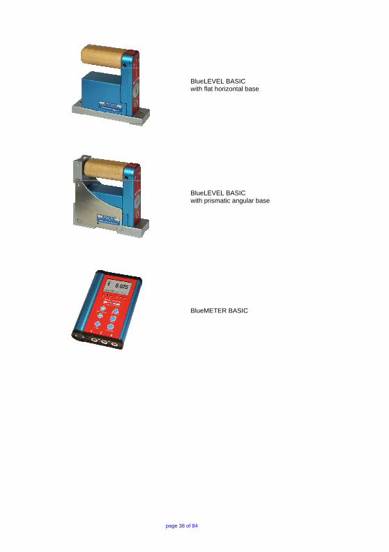
BlueLEVEL BASIC with flat horizontal base
BlueLEVEL BASIC with prismatic angular base
BlueMETER BASIC

page 39 of 84
A3 MEASURING PROCEDURE / GENERAL HANDLING TYPICAL CONFIGURATIONS WITHOUT RADIO TRANSMISSION
Used as stand alone instruments not possible as no display on the instruments. A BlueMETER BASIC is needed. Available sensitivities:
• 1µm/m (0.2 ArcSec) • 5µm/m (1 ArcSec) • 10µm/m (5 ArcSec)
Data transmission via cables Two BlueLEVEL BASIC and one BlueMETER BASIC
Wireless transmission of the measuring data (via Bluetooth™ wireless technology) Two BlueLEVEL BASIC with BlueMETER BASIC and Infrared-Zapper to initiate the measurement
Data transmission via cables to PC/Laptop Two BlueLEVEL BASIC with BlueMETER BASIC and infrared-zapper for triggering the data transmission
Wireless transmission of the measuring data (Bluetooth™ wireless technology) with connection to a PC / Laptop Two BlueLEVEL BASIC with BlueMETER BASIC and Infrared-Zapper to initiate the measurement
According to the WyBus compatibility scheme even more than 2 sensors can be connected to a BlueMETER BASIC. With connection via cables up to 63 sensors and with wireless data transmission up to 15 sensors are possible. One or two of sensors can be selected for display on the BlueMETER at a time.
page 40 of 84
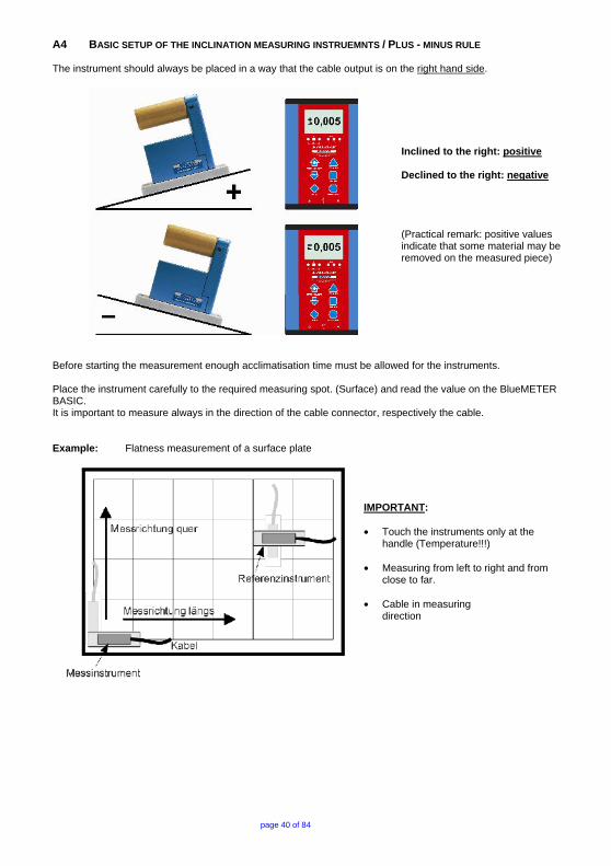
A4 BASIC SETUP OF THE INCLINATION MEASURING INSTRUEMNTS / PLUS - MINUS RULE The instrument should always be placed in a way that the cable output is on the right hand side.
Inclined to the right: positive Declined to the right: negative
(Practical remark: positive values indicate that some material may be removed on the measured piece)
Before starting the measurement enough acclimatisation time must be allowed for the instruments. Place the instrument carefully to the required measuring spot. (Surface) and read the value on the BlueMETER BASIC. It is important to measure always in the direction of the cable connector, respectively the cable. Example: Flatness measurement of a surface plate
IMPORTANT: • Touch the instruments only at the
handle (Temperature!!!)
• Measuring from left to right and from close to far.
• Cable in measuring direction

page 41 of 84
A5 ABSOLUTE MEASUREMENT / RELATIVE MEASUREMENT / DIFFERENTIAL MEASUREMENT Absolute measurement (Absolute ZERO) Condition for the absolute measurement is the performing of a reversal measurement
for determining the absolute zero (to the centre of the earth). After this procedure the instrument will display the effective deviation from the centre of gravity. This means the value is an absolute angle of the measured surface.
Example: if the object to be measured is absolutely level, the display is "0" Practical example
Position defined of the vertical spindle in relation to the machine table of a machine tool. Measurement with WYLER-software MT-SOFT
Relative measurement (Relative ZERO) A number of measurements do not require the absolute ZERO as described above.
Example: Angular deviation between two objects. (Lines, surfaces, guide ways) The measurement instrument is placed on an object and the displayed value is changed to "0". Then the instrument is relocated to a second object and the displayed value of the angle is the angular difference between the two surfaces. If the display is also "0", then both surfaces are parallel. Most important is that always the instrument is placed on both positions in the same direction.
Practical example
Flatness measurement with WYLER-software LEVELSOFT PRO

page 42 of 84
Differential measurement A differential measurement is a measurement with two instruments Measuring instrument (A) and Reference instrument (B), measuring the angular difference between the two. This means e.g. if the angular change in both instruments is the same the displayed value (Difference A - B) does not change. In principle this is a special relative measurement. In the following measuring tasks the differential measurement is especially used
• Measurement on object with vibrations imposed.
• Measurements on unstable systems or objects
Example: Measuring the flatness of a machine bed. The reference instrument is placed on a stable part of the machine where the measurement is not interfered. With the measuring instrument the measurement is taking place without removing the reference instrument.
Practical example
Flatness measurement with WYLER-software LEVELSOFT PRO

page 43 of 84
A6 GENERAL REMARKS ABOUT "ANGLES" AND "INCLINATION" Every angle may be defined in different ways. The most popular way is a definition in Degrees / Minutes / Seconds. This is shown in the graph. Such a definition is especially useful for larger angles.
With an angular measuring instrument not only an angle may be measured but also the height of a certain point over a defined base length can be calculated. for a profile of a line or a surface) Due to this simple and reliable method a number of tasks are possible, especially for measuring guide ways and surface plates definition.
Angle α = Height of the measuring point related to a defined base.
Height of the measuring point = tan α x length of base
Example: Angle = Height related to a defined base. e.g. 22 µm/m
Example: Because the relation µm/m is 1/1'000'000 the same relation can also be applied to micro inch/inch Angle = Height related to a defined base. e.g. 22 µm/m are equal to 22 micro inch/inch or 0,00002 Inch / Inch

page 44 of 84
A7 HEIGHT RELATED TO THE STEP LENGTH
Height Hx in [µm] related to step length
Height Hx [µm] = ]mm[LLength
]mm[LxSteplength]µm[HHeight ×
Height Hx in [micro Inch] related to step length 1 micro Inch = 0,000001 Inch
Height Hx [micro Inch] = ]Inch[LLength
]Inch[LxSteplength]mikroINCH[HHeight ×
because Length L = 1 Inch →
Height Hx [micro Inch] = Height H [micro Inch] x Step length Lx in [Inch]
Height Hx in [µm] related to step length
Height Hx [µm] = 1000][3600
sec][tan xmmLxLength
arc ×α
Height Hx in [micro Inch] related to step length 1 micro Inch = 0,000001 Inch
Height Hx [micro Inch] = 000'000'1]Inch[LxLength3600
sec]arc[tan ××α

page 45 of 84
A8 ZERO SETTING BY REVERSAL MEASUREMENT (ABSOLUTE ZERO) Using the reversal measurement is a simple way to determine the exact zero point deviation of the instrument (which can thus be compensated) as well as the exact inclination of the surface the instrument is placed
X
X
Reversal measurement for determining I. Zero point deviation of the instrument Nm II. Inclination of the measured surface Np
Zero point deviation of the instrument Nm:
Inclination of the measured surface Np:
Practical procedure: Prior to adjusting the zero point, the BlueLEVEL BASIC instrument should be allowed time to acquire the ambient, respectively the work-piece temperature. In addition the measuring system should be switched on for at least 1 minute (at least 3 minutes for instruments with sensitivity 1 µm/m)
- Slide the instrument onto a flat, horizontally levelled surface (e.g. engineer's surface plate)
- The position of the instrument is to be marked on the surface
Use the key <ON/MODE> on the BlueMETER BASIC to get to the menu point [ABS.ZERO] and confirm with <ENTER>. The following display is seen:
Use the zapper or confirm with <ENTER>. On the display the progress of the collected values are visible in graphic form.
When the curve is getting a straight line confirm the first value with the zapper or with <ENTER>

page 46 of 84
After the first reading the following display is seen:
This display means the first reading was successful. The instrument must be turned 180 degrees without lifting and slid exactly onto the previously marked position Use the zapper or confirm with <ENTER>. On the display the progress of the collected values are again visible in graphic form.
When the curve is getting a straight line confirm again the second value with the zapper or with <ENTER> After the second reading the following display is seen:
With this the reversal measurement is finished and the instrument shows the true absolute value.

page 47 of 84
B APPLICATIONS B1 MEASURING ABSOLUTE Zero point is to be set by reversal measurement. Now the BlueLEVEL BASIC will read deviations from the absolute horizontal position. Using BlueLEVEL BASIC with a BlueMETER BASIC the value of the display is shown in [Arcsec] or in [µm/m]. B2 RELATIVE MEASUREMENT It is not always required to set the instrument to zero by a reversal measurement (absolute ZERO). If e.g. the straightness of a line is measured most of the time the relative straightness is only required. The same applies when lines, parallels, flatness is measured with the WYLER LEVEL SOFT PRO. These are relative measurements. Using the machine tool software MT-SOFT an absolute measurement is important because different elements of a machine tool must be compared even at a later stage of the measurement. E.g. the horizontal guide way must be compared to the vertical axis of the spindle. Only when the measurement is done in absolute mode such a comparison is possible. B3 DIFFERENTIAL RESPECTIVELY REFERENCE MEASUREMENT USING AN ENGINEER SET Such a differential measurement, mostly done with an engineer set (two BlueLEVEL BASIC and one BlueMETER BASIC), is useful or necessary in some of the following cases:
• Measurement on an object with vibrations imposed • The inclination of the object to be measured will change by the weight of the instrument • The floor is unstable (heavy loads in the close surroundings) • The relative pitch and roll on a machine must be measured.
The Engineer set usually consists of: Two BlueLEVEL BASIC and one BlueMETER BASIC; Data transmission via cables
Picture: Two BlueLEVEL BASIC and
one BlueMETER BASIC
Connecting the instruments performing a differential measurement
• One of the instruments is used as measuring instrument and the other as reference instrument. • The measuring instrument is connected to port "A" the reference instrument to port "B". • Both instruments must be placed looking the same direction.

page 48 of 84
Examples for differential / reference measurement: R = Reference instrument, connected to port "B" M = Measuring instrument, connected to port "A"
Rectangularity resp. parallelism of machine spindle in relation to work table (Fig. 7). For precise square measurements an angular model fitted with magnets in the vertical face should be used. (Elimination of deformation due to manual pressure). Straightness of table motion (Fig. 8) in relation to the machine’s base. The table must be moved step by step and the measured value at each step should be noted/recorded after stabilisation only.

page 49 of 84
Inspection of perpendicularity and parallelism on large structures (Fig. 9). Suitable instrument for outdoor applications.
To conduct high precision measurements of parallelism (Fig 10) (e.g. guide way rails two or more) The reference instrument (R) will compensate for all changes in the objects orientation while measurements are made. Using this method the instrument (sensitivities up to 1 µm/m) allows determination of the exact shape of the guide ways.
Torsion in guide ways and work piece surfaces (Fig 11). The instrument (M) is moved step by step in direction of X, noting the reading at each step after allowing sufficient time for the instrument to settle. (Attention: Measuring axes have to be parallel!) This procedure is also applied when fastening work pieces in order to see possible tensions.

page 50 of 84
B4 ANGULAR MEASUREMENTS a) Small angles The measuring instruments BlueLEVEL and BlueLEVEL BASIC are especially well suited for measuring small angles. It is however to be considered that the larger the angle is getting, the larger the linearity error of the instrument is. It is therefore important to level the object to be measured (e.g. surface plate) as good as possible in both axes. b) 90°-angle (squareness) For measuring 90° angles (square angles) instruments with an angular base can best be used. Before starting a precision measurement the angular error of the instrument must be determined by a reversal measurement on a suitable object. After the reversal measurement precision measurement with measuring uncertainty of 3 to 5 µm/m is possible. The determination of the instrument's angular error is done as follows:
Index of correction = {(C + D)/2} - {(A + B)/2}
In the WYLER LEVELSOFT PRO a new set-up allows the easy measurement of squareness of rectangular objects. Principal procedure of a 90° measurement with WYLER LEVEL SOFT PRO The angular error of the instrument must be determined (optional) The measurement follows the required set-up (Step length, number of measurements etc.) After the measurement the respective lines may be adjusted according to different methods. For the following three methods the angular errors are computed and displayed:
• Method Endpoints • Method ISO1101 • Method Linear regression (least square)
Ask your local WYLER representative for further information on the software LEVEL SOFT PRO

page 51 of 84
B5 LINES AND FLATNESS MEASUREMENT (MANUAL PROCEDURE) A principal procedure of a measurement of a line with WYLER instruments is described below: Example:
• Sensitivity of the instrument 1 µm/m • Length of measuring base 200 mm/ step length 180 mm • The line to be measured must be divided in equal sizes according to the base available (calculated
step length) Overlapping of the steps is important, otherwise measuring errors are inevitable. • Place the instrument at the begin of the line measurement • Slide the instrument step by step along the line to be measured. Note all the measuring results after
allowing enough settling time. Then the line can be drawn as shown below considering the base length and the sensitivity of the instrument.
The picture to the left shows the measurement of a line using a BlueLEVEL BASIC combined with a BlueMETER BASIC with integrated radio module for wireless data transmission
Measurements on granite surface plates are done with instruments equipped with hardened steel bases with dust groves. The sharp edges prohibit dust particles to get between the plate and the base when sliding the instrument. The manual measuring and the computing effort is quite big - if possible at all - and the source of errors is large. Such a task is best done with the WYLER LEVELSOFT PRO.

page 52 of 84
C WYLER SOFTWARE LEVELSOFT PRO The WYLER software LEVELSOFT PRO is a well proven package based on ISO 1101 for measuring lines and surface flatness which is constantly upgraded to the demands of the user. The following measurements can be done with the WYLER LEVELSOFT PRO in combination with the correct measuring instruments:
• Lines (Straightness) • Lines with twist (torsion) • Parallelism • Rectangularity • Surface flatness • Partial surface flatness • Measurement on machine tools
Measurement of line according to ISO1101 with and without twist (torsion)
Measurement of parallel lines according to ISO1101 with and without twist (torsion)
Surface flatness according to ISO 1101 as well as "U-Jack" method
Rectangularity according to ISO1101

page 53 of 84
In order to connect the instruments to a PC/Laptop a cable connection between the BlueMETER BASIC and the PC/Laptop is required. Remarks:
With the Software LEVELSOFT PRO the instruments of the BlueSYSTEM BASIC are automatically recognised
Address, respectively serial number(s) of the instruments
As a new feature the address, respectively serial number of the instruments is displayed.

page 54 of 84
D SOFTWARE FOR THE DEFINITION OF MACHINE TOOL GEOMETRY MACHINE TOOL INSPECTION SOFTWARE MT-SOFT
MT-SOF gives the possibility to measure individual elements of machine tools with standard inclination measuring instruments. The measured results can be saved and at a later stage used for comparison and put together to receive a thorough result of the over all accuracy of the machine tool. E.g. the horizontal guideway must be compared to the vertical axis of the spindle. Only when the measurement is done in absolute mode such a comparison is possible. The logical and clear structure of the software makes even the measurement of complex machines an easy task.
The following measurement tasks can be done by using suitable instruments and the WYLER MT-SOFT:
• GUIDE WAYS • ROTATING AXIS • ROTATION OF MACHINE TOOL ELEMENTS • CIRCLES
GUIDE WAYS Measurement of guide ways using inclination
measuring instruments
ROTATING AXIS Definition of rectangularity between the surface of the
table and the vertical rotating spindle
ROTATION OF MACHINE TOOL ELEMENTS Measuring and defining the geometrical roll and pitch errors on a machine tool element moving horizontally
CIRCLES Flatness measurement and defining the position in
space of circles as well as co planarity of circles.
page 55 of 84
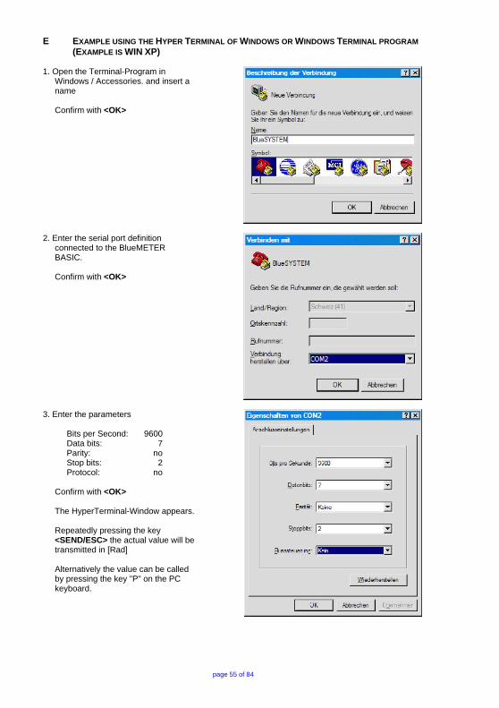
E EXAMPLE USING THE HYPER TERMINAL OF WINDOWS OR WINDOWS TERMINAL PROGRAM (EXAMPLE IS WIN XP) 1. Open the Terminal-Program in
Windows / Accessories. and insert a name
Confirm with <OK>
2. Enter the serial port definition connected to the BlueMETER BASIC.
Confirm with <OK>
3. Enter the parameters
Bits per Second: 9600 Data bits: 7 Parity: no Stop bits: 2 Protocol: no
Confirm with <OK> The HyperTerminal-Window appears. Repeatedly pressing the key <SEND/ESC> the actual value will be transmitted in [Rad] Alternatively the value can be called by pressing the key "P" on the PC keyboard.

page 56 of 84
Example: Two BlueLEVEL BASIC and a BlueMETER BASIC are connected
Remark: The configuration has to be done first on the BlueMETER BASIC
• 1 BlueLEVEL BASIC with the address H0200 is connected to Port “A” • 1 BlueLEVEL BASIC with the address H0201 is connected to Port “B” • Measuring-mode: Display of values instruments on Port "A" and "B" simultaneously
Meaning of the display:
090
H0200B
+0.000022
H0201B
-0.000048
Continuous number BlueLEVEL BASIC with the address H0200 is connected to Port “A” +0.000022 Rad respectively +22 µRad BlueLEVEL BASIC with the address H0201 is connected to Port “B” -0.000048 Rad respectively -48 µRad

page 57 of 84
F WYBUS COMPATIBLE INSTRUMENTS The WyBus concept allows to connect, besides the new sensors, also most of the previous sensors to a BlueMETER, a BlueMETER BASIS or a BlueTC. It is, however, important to differentiate whether they are connected through a short cable, through a longer cable up to maximum 1200 m or via wireless transmission. F1 CONNECTION THROUGH A SHORT CABLE The following sensors can be connected through a cable of maximum 15 m length to a BlueMETER, a BlueMETER BASIC or a BlueTC.
• BlueLEVEL • Zerotronic • Clinotronic • Minilevel NT • Zeromatic2/1 • Zeromatic2/2
Through a cable of maximum 15 m length and with a BlueTC as an intermediate the following sensors can be connected:
• Zerotronic • Clinotronic • Minilevel NT • Zeromatic2/1 • Zeromatic2/2
F2 CONNECTION THROUGH A LONG CABLE OR THROUGH WIRELESS TRANSMISSION The following sensors can be connected through a cable of maximum 1200 m length or via wireless data transmission to a BlueMETER, a BlueMETER BASIC or a Blue TC:
• BlueLEVEL • Zeromatic2/1 • Zeromatic2/2
Through a cable of maximum 1200 m length or via wireless data transmission and with a BlueTC as an intermediate the following sensors can be connected:
• Zerotronic • Clinotronic • Minilevel NT • Zeromatic2/1 • Zeromatic2/2

page 58 of 84
G SPECIAL FUNCTIONS G1 RESET TO FACTORY PRE-SETTINGS You can reset all adjustments and settings to the factory pre-settings. For this action press simultaneously the keys <ENTER> and <ON/MODE> until an arrow to the right hand side appears in the display.
The following values will be set and the following actions performed: BlueMETER:
• Filter Type 3 • Unit mm/m • Display mode Absolute • Relative Base in millimetres, value 1000 • Relative Base in Inch, value 10 • All members of the wireless data transmission group are deleted • All members of the list of instruments are deleted
BlueLEVEL
• Filter Type 3 • Unit set to
o 1μ instrument: mm/m, 3 decimals o 5μ instrument: mm/m, 3 decimals, rounded to 5µm/m o 10μ instrument: mm/m, 2 decimals
• Display mode Absolute • Relative Base in millimetre, value 1000 • Relative Base in Inch, value 10 • All members of the wireless data transmission group are deleted • Relative Zero is set to 0 • Absolute Zero is set to 0
G2 FIRMWARE VERSION With a special key operation you can read the version number of the firmware installed. After turning off the instrument hold the <ON/MODE> key down for another 10 seconds.
The display shows in large figures the date of issue and at the bottom the version number of the firmware.

page 59 of 84
H TECHNICAL DATA BLUESYSTEM BASIC H1 TECHNICAL DATA OF THE RADIO MODULES BLUESYSTEM BASIC (OPTIONAL)
SENDER / RECEIVER SENDER / EMPFÄNGER BlueSYSTEM with Bluetooth™ wireless technology
Frequency ISM-Band / 2,4000 - 2,4835 GHz
Modulation FHSS (Frequency Hopping Spread Spectrum)
Used Net-structure Point to point / Point to multi-point
RF Output power Max. +17 dBm / Class 1
Sensitive level Receiver -80 dBm
Batteries BlueLEVEL / BlueTC Batteries BlueMETER
2 x 1.5V, Size “C” Alkaline 3 x 1.5V, Size “C” Alkaline
H2 TECHNICAL DATA BLUELEVEL BASIC
Sensitivity / Empfindlichkeit 1 µm/m 0.2 Arcsec
5 µm/m 1 Arcsec
10 µm/m 2 Arcsec
Display range external display / Anzeigebereich externe Anzeige ± 10 mm/m ± 50 mm/m ± 100 mm/m
Limits of error / Fehlergrenze <0.5 Full-scale (DIN 2276)
max. 1% of measured value / max. 1% des aktuellen Messwertes
Limits of error / Fehlergrenze >0.5<Full-scale (DIN 2276)
max. 1% of (2 x measured value - 0.5 x Full-scale) / max. 1% von (2 x aktueller Messwert - 0.5 x Messbereichsendwert)
Temperature error / Temperaturkoeffizient /°C max. 0.1% Full-scale / max. 0.1% Messbereichsendwert
Display available / Anzeige verfügbar within 3 seconds / innerhalb von 3 Sekunden
Digital output / Digitalausgang RS232 / RS422 / RS485, asynchron, 7 DataBits, 2 StopBits, no parity, 9600 bps
External power supply Externe Stromversorgung
BlueMETER BASIC: + 5V DC, max. 450 mW or/oder 8…28 V DC
Operating temperature range / Betriebstemperatur Storage temperature range / Lagertemperatur
0 ... +40°C -20 ... +70°C
Net weight without measuring base, including batteries and handle Netto-Gewicht ohne Messbasis, inklusive Batterien und Griff
BlueLEVEL BASIC: 1200g BlueMETER BASIC: 775g

page 60 of 84
H3 TECHNICAL DATA OF THE BLUEMETER BASIC
Display available / Anzeige verfügbar within 3 seconds / innerhalb von 3 Sekunden
Digital output / Digitalausgang RS232 / RS422 / RS485, asynchron, 7 DataBits, 2 StopBits, no parity, 9600 bps
External power supply Externe Stromversorgung
BlueMETER BASIC: + 5V DC, max. 450 mW or/oder 8…28 V DC
Operating temperature range / Betriebstemperatur Storage temperature range / Lagertemperatur
0 ... +40°C -20 ... +70°C
Net weight, including batteries Netto-Gewicht, inklusive Batterien BlueMETER BASIC: 775g
H4 PIN-DEFINITION FOR BLUELEVEL + BLUEMETER,
BLUELEVEL + BLUEMETER BASIC AND BLUETC
RS485
Binder Series 712 / 8 pol. (female)
RS232 Sub-D / 9 pol. (female)
Pin Number Pin Name Pin Type Pin Function
1 VPP Power in Unregulated Power 2 VSS GND Ground 3 VDD Power out Power +5V 4 RTA Input/Output RS485-Line A 5 RTB Input/Output RS485-Line B 6 - - - 7 - - - 8 KEY* Input Trigger Key
* Measuring can be triggered via "Key-Cable" / WY 065-025-KEY
page 61 of 84
I SERVICE AND REPAIR I1 REPAIR OF MEASURING INSTRUMENTS AND DISPLAY UNITS Normally any instruments requiring repair can be sent to the local WYLER partner (local distributor) who will take the necessary steps and make the arrangements for repair on behalf of the customer. Express Repair Service, ERS A large number of customers can not miss the instruments for a longer period as these are in daily operation. For these cases WYLER SWITZERLAND has created a new service called "Express Repair Service, ERS". Employing this service the transport time from the user to WYLER SWITZERLAND and back and thus the complete repair time can be reduced considerably. A simplified description of this service:
• The customer announces the repair request to the local WYLER partner in his country. • The WYLER partner will inform the customer about the possibility of the ERS service outlining the
advantages and consequences of this service, such as e.g. o reduced total repair time o required acceptance to repair without quote up to 65 % of the price for a new instrument o suitable packing for air transport o expenses of the ERS
• In case the customer decides to use the ERS, the customer informs the local WYLER partner or directly WYLER SWITZERLAND providing the necessary data.
• The customer will receive all information and instructions necessary for a smooth handling, the customer has just to pack the product suitably and to fill in a form for the TNT courier service as well as to announce the readiness to the local TNT office for pick-up. Everything else will run automatically.
• Products reaching WYLER SWITZERLAND under this service will be handled with first priority, and the instrument will be returned using the same carrier.
• The invoicing will be through the WYLER partner in your country. Please do not hesitate to make use of this service in order to have your WYLER instrument back at your disposal as soon as possible. In case of any questions please contact WYLER SWITZERLAND or your local distributor, we will gladly help you to use the ERS successfully. WYLER AG Im Hölderli CH-8405 WINTERTHUR Switzerland
Tel. 0041 (0) 52 233 66 66Fax. 0041 (0) 52 233 20 53
Homepage: http://www.wylerag.comE-Mail: [email protected]

page 62 of 84
I2 SERVICE- AND MAINTENANCE CONTRACTS Measuring systems are becoming more and more complex and are therefore subject to continuous supervision in respect of quality and reliability. For this purpose WYLER AG offers the option of a MAINTENANCE CONTRACT with the purchase of new instruments.
Such a MAINTENANCE CONTRACT offers the following services to the customer:
• Complete inspection and re-adjustment of the instrument / system in a bi-yearly interval.
• The scope of delivery includes an internationally recognised Calibration Certificate SCS for the entire system confirming the performance after the service intervention. Traceable certificates SCS are issued according to our accreditation as a calibration laboratory by the Swiss authorities
• Highest priority for any repair works (actual repair work is not included and will be quoted separately)
• Technical enhancements and modifications published by WYLER, if considered suitable
• Costs for packing and transport of the instrument(s) from the customer to WYLER and back, either directly or through the WYLER distribution partner
• Extension of warranty period to 24 months: If a maintenance contract is signed within 6 months of the purchasing of a new instrument the warranty period is extended to 24 month.
Options:
Depending on the customers requirement the re-calibration interval can be shortened (every year) or be extended (every 3rd year)
The following services are excluded from all maintenance contracts:
• The contract does not include any repair work. If it is determined during the inspection or the re-calibration process that the instrument requires repair, such work will be quoted separately to the customer.
We help you to keep your valuable and important instruments always accurate and ready for use! We would be glad to offer you a maintenance contract adapted to your specific requirements.

page 63 of 84
J STORAGE OF THE INSTRUMENTS / CARE AND HANDLING OF THE BATTERIES J1 STORAGE OF THE INSTRUMENTS For storage periods the measuring instrument should be placed in a position in which the instruments are also used when measuring (upright position). Unsuitable storage may result in a longer period of zero creeping due to overload of the pendulum system.
J2 CARE AND HANDLING OF THE BATTERIES BATTERY REPLACEMENT
BlueLEVEL BASIC: 2 pieces 1.5V, Size “C” ALKALINE BlueMETER BASIC: 3 pieces 1.5V, Size “C” ALKALINE
Read the instructions in your manual before installing batteries. Make sure to insert the batteries properly, following the symbols showing you the correct way to position the positive (+) and negative (-) ends of the batteries. Keep battery contact surfaces clean by gently rubbing with a clean pencil eraser or cloth. Replace batteries with the size and type specified by the device's manufacturer. Remove all used batteries from the device at the same time, and then replace them with new batteries of the same size and type. Store batteries in a cool dry place at normal room temperature. Remove batteries from devices that will be stored for extended periods. Don't dispose of batteries in a fire - they may rupture or leak. Don't recharge a battery unless it is specifically marked "rechargeable." Attempting to recharge a normal battery could result in rupture or leakage. Disposal of Batteries / Accumulators You are required by law (Battery Ordinance) to return all spent batteries/accumulators. Disposing of spent batteries/accumulators in the household waste is prohibited! Batteries / accumulators that contain hazardous substances are marked with the symbols on the side. These symbols indicate that it is prohibited to dispose of these batteries in the household waste. You can return spent batteries respectively accumulators that can no longer charged free of charge to the collection points in your community, our outlets or everywhere else where batteries or accumulators are sold. You thus fulfil the legal requirements and contribute to the protection of our environment!

page 64 of 84
K ACCREDITATION BLUETOOTH™ WIRELESS TECHNOLOGY FOR BLUESYSTEM K1 MANUFACTURER DECLARATION OF CONFORMITY (DOC) We,
Name: WYLER AG Im Hoelderli CH-8405 Winterthur / Switzerland
Phone : +41 52 233 66 66 Fax: +41 52 233 20 53 Homepage: http://www.wylerag.com E-Mail: [email protected]
declare under our sole responsibility, that the Products:
Inclination Measuring System “Engineer set BlueSYSTEM BASIC” with Bluetooth™ wireless technology, consisting of
• BlueSYSTEM BASIC-Set No. 021Fxxx-yyy-0zz
• BlueLEVEL BASIC No. 017Fxxx-yyy-sss
• BlueMETER BASIC No. 017F004-RED
The letter “F” indicates: with integrated Bluetooth-Module
to which this declaration relates is in conformity with the essential requirements and other relevant requirements of the R&TTE Directive 1999/5/EC. The products comply with the following standards and other normative documents: RF: EN 300 328-2 V1.1.1 (2000-07) Low Voltage Directive: 73/23/EEC “safety”
EN 60950, EN 61131-2 (radio) IEC 60601-1-2 medical electrical equipment (radio)
EN 61010-1 (BlueSYSTEM BASIC) EMC 89/336/EEC: EN 61000-6-3: 2001 emission
EN 61000-6-1 : 2001 immunity (generic standard, household and light industrial environment)
EN 61000-6-4: 2001 emission EN 61000-6-2 : 2001 immunity
(generic standard, industrial environment) EN 301 489-1 V1.3.1: (2001-09) EN 301 489-17 V1.1.1: (2000-09) For information: On the base of this DoC, the products will bear following mark:
Place & Date of issue: CH-Winterthur, 01.07.2005 Signed by the manufacturer: Mr. H. E. Hinnen Title: Managing Director Engineering / R&D

page 65 of 84
K2 BLUETOOTH EQUIPMENT BlueSYSTEM-Instruments are equipped with OEM Serial Port Adapter 33i, 2nd Generation With Bluetooth™ wireless technology Manufacturer: connectBlue AB Stora Varvsgatan 11 N: 1 SE-211 19 Malmö, Sweden Product Name: OEM SPA33i, with internal antenna (SMD-Type) OEM Module ID: cB-0702-01 Type: BT-Class 1 / max. +20dBm RF-Output Power: < 16dBm/100kHz e.i.r.p. Antenna: integral (SMD) Qualified Bluetooth Product, with Bluetooth ID: B00931 QPN: GRA_001_03.pdf
K3 FCC Compliance FCC Statement for cB-0702-02
This device complies with Part 15 of the FCC Rules. Operation is subject to the following two conditions: (1) this device may not cause harmful interference, and (2) this device must accept any interference received, including interference that may cause undesired operation. NOTE: This equipment has been tested and found to comply with the limits for a Class B digital device, pursuant to Part 15 of the FCC Rules. These limits are designed to provide reasonable protection against harmful interference in residential installation. This equipment generates, uses and can radiate radio frequency energy and, if not installed and used in accordance with the instructions, may cause harmful interference to radio communications. However, there is no guarantee that interference will not occur in a particular installation. If this equipment does cause harmful interference to radio or televisions reception, which can be determined by turning the equipment off and on, the user is encouraged to try to correct the interference by one or more of the following measures:
• Reorient or relocate the receiving antenna • Increase the separation between the equipment and receiver • Connect the equipment into an outlet on a circuit different from that to which the receiver is connected • Consult the dealer or an experienced radio/TV technician for help
This device contains FCC ID: PVH070201

page 66 of 84
K4 COUNTRY SPECIFIC INFORMATION FOR BLUETOOTH RADIO LINK (>10MW RF-POWER) List of European Countries with Notification, without Restrictions:
General Hereby, Wyler AG, CH-8405 WINTERTHUR, declares that “BlueSYSTEM” and its components (2.400 - 2.4835 GHz) are in compliance with the essential requirements and other relevant provisions of Directive 1999/5/EC.
GB Hereby, Wyler AG, CH-8405 WINTERTHUR, declares that “BlueSYSTEM” and its components (2.400 - 2.4835 GHz) are in compliance with the essential requirements and other relevant provisions of Directive 1999/5/EC.
NL Hierbij verklaart Wyler AG, CH-8405 WINTERTHUR dat “BlueSYSTEM” en zijn componenten (2.400 - 2.4835 GHz) in overeenstemming zijn met de essentiële eisen en de andere relevante bepalingen van richtlijn 1999/5/EG.
SE Härmed intygar Wyler AG, CH-8405 WINTERTHUR att “BlueSYSTEM” och deras komponenter (2.400 - 2.4835 GHz) stämmer överens med de väsentliga egenskapskrav och övriga relevanta bestämmelser som framgår av direktiv 1999/5/EG.
DE Hiermit erklärt Wyler AG, CH-8405 WINTERTHUR, dass sich „BlueSYSTEM“ und seine Geräte (2.400 - 2.4835 GHz) in Übereinstimmung mit den grundlegenden Anforderungen und den anderen relevanten Vorschriften der Richtlinie 1999/5/EG befinden.
CZ Tímto firma Wyler AG,CH-8405 Winterthur, deklaruje, ze " BlueSYSTEM" a jeho soucásti, jsou v souladu s nezbytnými pozadavky a s ostatními príslusnými podmínkami smernice 1999/5/EC.
CH Hiermit erklärt Wyler AG, CH-8405 WINTERTHUR, dass sich „BlueSYSTEM“ und seine Geräte (2.400 - 2.4835 GHz) in Übereinstimmung mit den grundlegenden Anforderungen und den anderen relevanten Vorschriften der Richtlinie 1999/5/EG befinden.
NO Herved erklærer Wyler AG, CH-8405 WINTERTHUR, at „BlueSYSTEM“ og deres komponenter (2.400 - 2.4835 GHz) stemmer overens med de vesentlige egenskapskrav og øvrige relevante bestemmelser som fremgår av direktiv 1999/5/EG.

page 67 of 84
List of European Countries with Notification, with Restrictions:
FR
Par la présente Wyler AG, CH-8405 WINTERTOUR déclare que les instruments “BlueSYSTEM et ses composants (2.400 - 2.4835 GHz) sont conforme aux exigences essentielles et aux autres dispositions pertinentes de la directive 1999/5/CE. Attention: En France (07/2005) les contraintes géographiques sont a respecter : L’utilisation de l’équipement bluetooth (>10mW) à l’extérieur des bâtiments sur le domaine public n’est pas possible Attention: In France (07/2005) the geographic restrictions must be respected. The use of Bluetooth™ equipment (>10 mW) outside of buildings in the public domain is not possible.
IT
Con la presente Wyler AG, CH-8405 WINTERTHUR dichiara che questo instrumenti “BlueSYSTEM” (2.400 - 2.4835 GHz) sono conforme ai requisiti essenziali ed alle altre disposizioni pertinenti stabilite dalla direttiva 1999/5/CE. Attenzione: In Italia (07/2005) vanno osservate le limitazioni geografiche : L’equipaggiamento deve essere utilizzato solo all’interno dell’edificio / dell’area aziendale. Attention: In Italy (07/2005) the geographic restrictions must be respected. Bluetooth™ equipment must be used inside of buildings / factory areas only.
List of Countries with notification:
JPN
Hereby, Obishi Co., Ltd, JP-940-1164 Nagaoka-City Niigata, declares that “BlueSYSTEM” and its components (2.400 - 2.4835 GHz) are in compliance with the essential requirements and other relevant provisions of ARIB Standard – T66, Version 2.1 .
List of Countries with pending Notification:
• Russia • Canada • China • Taiwan • South Korea • India • Thailand • Australia

page 68 of 84
L FLOWCHARTS (BLUEMETER BASIC ONLY) L1 POWER UP

page 69 of 84
L2 SAMPLING

page 70 of 84
L3 SENSOR

page 71 of 84
L4 REFRESH
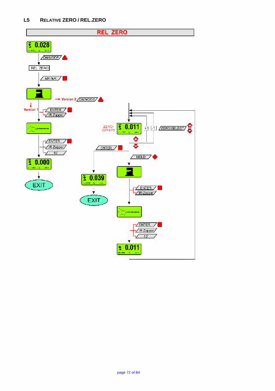
page 72 of 84
L5 RELATIVE ZERO / REL.ZERO

page 73 of 84
L6 UNIT

page 74 of 84
L7 ABSOLUTE ZERO / ABS.ZERO

page 75 of 84
L8 FILTER

page 76 of 84
L9 RADIO TRANSMISSION

page 77 of 84
L10 JOIN

page 78 of 84
L11 LEAVE

page 79 of 84
L12 HOLD

page 80 of 84
M INDEX Key word Chapter Page A ABSOLUTE 4.4 18 ABSOLUTE MEASUREMENT / RELATIVE MEASUREMENT / DIFFERENTIAL MEASUREMENT A5 41 ABSOLUTE ZERO 4.4 25 ABSOLUTE ZERO / ABS.ZERO (FLOWCHART) L7 68 ACCREDITATION BLUETOOTH ® WIRELESS TECHNOLOGY FOR BLUESYSTEM K 64 ADDITIONAL FUNCTIONS OF THE BLUEMETER BASIC 4.4 27 ADDITIONAL MANUALS 6 ANGULAR MEASUREMENTS B4 50 APPENDIX 36 APPLICATIONS B 47 B BASIC SETUP OF THE INCLINATION MEASURING INSTRUEMNTS / PLUS - MINUS RULE A4 40 BASICS / INTRODUCTION 1 6 BASICS AND GENERAL REMARKS ABOUT BLUESYSTEM BASIC AND INCLINATION MEASUREMENT
A 36
BATTERIES IN BLUEMETER BASIC 2.1 7 BATTERY COMPARTMENT 4.3 17 BATTERY POWER 2.2 8 BATTERY REPLACEMENT J2 63 BEFORE STARTING 2 7 BLUELEVEL BASIC A2 7 BLUELEVEL BASIC (OVERVIEW) 3.1 12 BLUELEVEL BASIC WITH PRISMATIC ANGULAR BASE A2 38 BLUEMETER BASIC 4 15 BLUEMETER BASIC A2 37 BLUESYSTEM BASIC FAMILY 1 6 BLUESYSTEM BASIC FAMILY A1 36 BLUESYSTEM FAMILY A2 37 BLUETOOTH EQUIPMENT K2 65 C CARE AND HANDLING OF THE BATTERIES J2 63 CONFIGURATIONS WITH BLUEMETER AND THE BLUELEVEL BASIC 4.2 16 CONNECTING THE INSTRUMENTS 2.3 9 CONNECTION TO PC OR LAPTOP 2.3 9 CONTENT 3 COUNTRY SPECIFIC INFORMATION FOR BLUETOOTH RADIO LINK K4 66 D DATA TRANSMISSION VIA CABLES TO PC/LAPTOP A3 39 DEACTIVATING THE AUTOMATIC INSTRUMENT SHUT OFF OF THE BLUEMETER BASIC
4.6.1 29
DESCRIPTION OF THE BLUEMETER BASAIC WITHOUT RADIO MODULE 4 15 DESCRIPTION OF THE KEYS AND FUNCTION OF THE BLUELEVEL BASIC WITH CABLE TRANSMISSION
3 12
DESCRIPTION OF THE VARIOUS KEYS 4.6.1 29 DESCRIPTION OF VARIOUS DISPLAY FORMS ON THE BLUEMETER BASIC 4.6.2 32 DIFFERENTIAL MEASUREMENT 4.4 22 DIFFERENTIAL MEASUREMENT / ABSOLUTE MEASUREMENT / RELATIVE MEASUREMENT A5 41 DIFFERENTIAL RESPECTIVELY REFERENCE MEASUREMENT USING AN ENGINEER SET B3 47 DIRECTION OF THE VALUE’S INCLINATION 4.6.2 32 DISPLAY 4.4 18 DISPLAY FORMS ON THE BLUEMETER BASIC 4.6.2 32 DISPLAY OF THE ACTUAL BATTERY POWER 2.2 8 E ENDPOINTS / METHOD ENDPOINTS B4 50 ENGINEER SET 1 6 ENGINEER SET A1 37

page 81 of 84
ENTER – KEY 4.6.1 30 ERS / EXPRESS REPAIR SERVICE, ERS I1 61 EXPRESS REPAIR SERVICE, ERS I1 61 F FACTORY PRE-SETTINGS / RESET TO FACTORY PRE-SETTINGS G1 58 FCC COMPLIANCE K3 65 FILTER (FLOWCHART) L8 75 FIRMWARE VERSION G2 58 FLATNESS MEASUREMENT OF A SURFACE PLATE A4 40 FLOWCHART ABSOLUTE ZERO / ABS.ZERO L7 68 FLOWCHART FILTER L8 75 FLOWCHART HOLD L12 79 FLOWCHART JOIN L10 77 FLOWCHART LEAVE L11 78 FLOWCHART POWER UP L1 68 FLOWCHART RADIO TRANSMISSION L9 76 FLOWCHART REFRESH L4 71 FLOWCHART RELATIVE ZERO / REL.ZERO L5 72 FLOWCHART SAMPLING L2 69 FLOWCHART SENSOR L3 70 FLOWCHART UNIT L6 73 FLOWCHARTS ( ONLY BLUEMETER BASIC) L 68 FUNCTIONAL MENU WITH BLUEMETER BASIC USING THE FUNCTION KEY 4.4 18 G GENERAL REMARKS ABOUT “ANGLES” AND “INCLINATION” A6 43 H HEIGHT RELATED TO THE STEP LENGTH A7 44 HIGH PRECISION MEASUREMENTS OF PARALLELISM B3 48 HOLD – KEY 4.6.1 31 HOLD (FLOWCHART) L12 79 HYPER TERMINAL OF WINDOWS E 55 I / J INDEX M 80 INDEX OF CORRECTION B4 50 INITIAL STARTUP OF THE INSTRUMENTS 2.2 8 INSERTING RESPECTIVELY REPLACEMENT OF BATTERIES IN BLUEMETER BASIC 2.1 7 INSPECTION OF PERPENDICULARITY AND PARALLELISM ON LARGE STRUCTURES B3 49 INTRODUCTION TO THE BLUESYSTEM BASIC A1 36 ISO1101 / METHOD ISO1101 B4 50 JOIN (FLOWCHART) L10 77 L LARGE ANGLES UP TO 90 DEGREES B4 50 LEAVE (FLOWCHART) L11 78 LEVELSOFT PRO A5 41 LEVELSOFT PRO / WYLER SOFTWARE LEVELSOFT PRO C 52 LINEAR REGRESSION (LEAST SQUARE) / METHOD LINEAR REGRESSION (LEAST SQUARE) B4 50 LINES AND FLATNESS MEASUREMENT B5 50 M MAINTENANCE AND SERVICE CONTRACTS I2 62 MANUFACTURER DECLARATION OF CONFORMITY K1 64 MEASURING ABSOLUTE B1 47 MEASURING PROCEDURE / GENERAL HANDLING A3 39 MEASURING UNIT 4.6.2 35 MEASURING UNITS 4.4 24 MENU 4.6.2 32 METHOD ENDPOINTS B4 50 METHOD ISO1101 B4 50 METHOD LINEAR REGRESSION (LEAST SQUARE) B4 50 MT-SOFT / SOFTWARE FOR THE DEFINITION OF MACHINE TOOL GEOMETRY MACHINE TOOL INSPECTION SOFTWARE MT-SOFT
D 54

page 82 of 84
O ON/MODE 4.4 18 ON/MODE - KEY 4.6.1 29 OPERATING THE BLUEMETER BASIC 4.6 29 OVERVIEW OF THE BLUEMETER BASIC 4.3 17 P PIN-DEFINITION FOR BLUELEVEL + BLUEMETER, BLUELEVEL + BLUEMETER BASIC AND BLUETC
H4 60
POWER UP (FLOWCHART) L1 68 PREPARATION AND STARTUP 2 7 R RADIO TRANSMISSION (FLOWCHART) L9 76 REAR VIEW BLUELEVEL BASIC 3.2.1 13 RECTANGULARITY RESP. PARALLELISM OF MACHINE SPINDLE IN RELATION. TO WORK TABLE B3 47 REFRESH (FLOWCHART) L4 71 REL ZERO 4.4 21 REL ZERO OFFSET 4.4 18 RELATIVE MEASUREMENT B2 47 RELATIVE MEASUREMENT / DIFFERENTIAL MEASUREMENT / ABSOLUTE MEASUREMENT A5 41 RELATIVE ZERO / REL.ZERO (FLOWCHART) L5 72 REPAIR AND SERVICE I 61 REPLACEMENT OF BATTERIES IN BLUEMETER BASIC 2.1 7 RESET TO FACTORY PRE-SETTINGS G1 58 REVERSAL MEASUREMENT 4.4 25 REVERSAL MEASUREMENT A5 41 REVERSAL MEASUREMENT (ABSOLUTE ZERO) A8 45 S SAMPLING (FLOWCHART) L2 69 SEND/ESC- KEY 4.6.1 30 SENSITIVITIES A3 39 SENSOR 4.4 18 SENSOR (FLOWCHART) L3 70 SENSOR-ADDRESS 4.6.2 35 SERVICE- AND MAINTENANCE CONTRACTS I2 62 SERVICE AND REPAIR I 61 SHUT-OFF SYSTEM 4.1 15 SMALL ANGLES B4 50 SOFTWARE FOR THE DEFINITION OF MACHINE TOOL GEOMETRY MACHINE TOOL INSPECTION SOFTWARE MT-SOFT
D 54
SPECIAL FUNCTIONS G 58 STARTING THE BLUEMETER 4.1 15 STARTUP AND PREPARATION 2 7 STATUS OF BATTERY POWER "BATT" 4.6.2 33 STORAGE INSTRUMENTS J1 63 STORAGE INSTRUMENTS / CARE AND HANDLING OF THE BATTERIES J 63 STRAIGHTNESS OF TABLE MOTION B3 47 SYSTEM CHECK 4.6.1 30 T TEACH-IN OF THE IR-TRIGGER 4.5 28 TECHNICAL DATA BLUELEVEL BASIC H2 59 TECHNICAL DATA BLUESYSTEM BASIC H 59 TECHNICAL DATA OF THE BLUEMETER BASIC H3 60 TECHNICAL DATA OF THE RADIO MODULES BLUESYSTEM BASIC (OPTIONAL) H1 59 TOP VIEW BLUELEVEL BASIC 3.2.2 13 TORSION IN GUIDE WAYS AND WORK PIECE SURFACES B3 49 TYPICAL CONFIGURATIONS WITHOUT RADIO TRANSMISSION A3 39 UNIT (FLOWCHART) L6 73 V VIEW OF FUNCTIONAL KEYS BLUELEVEL BASIC 3.2 13 W

WIRELESS TRANSMISSION OF THE MEASURING DATA (BLUETOOTH™WIRELESS TECHNOLOGY) A3 39 WYBUS COMPATIBLE INSTRUMENTS F 57 WYLER SOFTWARE LEVELSOFT PRO C 52 Z ZAPPER 4.5 28 ZERO OFFSET 4.4 18 ZERO SETTING BY REVERSAL MEASUREMENT (ABSOLUTE ZERO) A8 45 ZERO/SELECT "±" – KEYS 4.6.1 31

WYLER AG Im Hölderli CH-8405 WINTERTHUR Switzerland
Tel. 0041 (0) 52 233 66 66 Fax. 0041 (0) 52 233 20 53
Homepage: http://www.wylerag.com
E-Mail: [email protected]