Blown Electrostatic Flock Application System Operating Manual.pdf · Blown Electrostatic Flock...
33
AeroFlocker Operators Manual Campbell Coutts Ltd – 20 th January 2010 page 1 Blown Electrostatic Flock Application System Table of Contents
Transcript of Blown Electrostatic Flock Application System Operating Manual.pdf · Blown Electrostatic Flock...

AeroFlocker Operators Manual
Campbell Coutts Ltd – 20th January 2010 page 1
Blown Electrostatic Flock Application System
Table of Contents

AeroFlocker Operators Manual
Campbell Coutts Ltd – 20th January 2010 page 2
Page Number Topic
3 Glossary
4 Checking the Package Contents
5 Introduction to the AeroFlocker
6 Health & Safety Warnings
7 The Control Panel
7 Panel Meter
7 Mains Power Switch & Indicator Fuse
8 Setting and using the Auto/Manual/Off Controls
9 How to set the High Voltage
10 How to set the Blower speed
11 How to set the Brush speed
12 The AeroFlocker Applicator Gun
13 Connecting the Applicator Gun to the AeroFlocker
14 Filling of Flock in the AeroFlocker
14 & 15 Changing & Emptying of Flock in the AeroFlocker
16 The Flock Dispensing Mesh
16 Changing the Flock Dispense Mesh
17 AeroFlocker Operating Instructions
17 Connection of Flocking Earth Lead
17 & 178 How to Flock using the AeroFlocker
19 Optional Electrostatic Applicator Assembly
20 Connecting the Electrostatic Applicator the AeroFlocker
21 Filling, Changing and Emptying Flock in the Electrostatic Applicator
22 & 23 Flocking using the optional Electrostatic Applicator
24, 25, 26 & 27 AeroFlocker suggested Spare Parts and Optional Extras
28 AeroFlocker Technical Specifications
29 Optional Electrostatic Applicator Technical Specifications
30, 31, 32, 33 Trouble Shooting Guide
AeroFlocker Operators Manual
Campbell Coutts Ltd – 20th January 2010 page 3
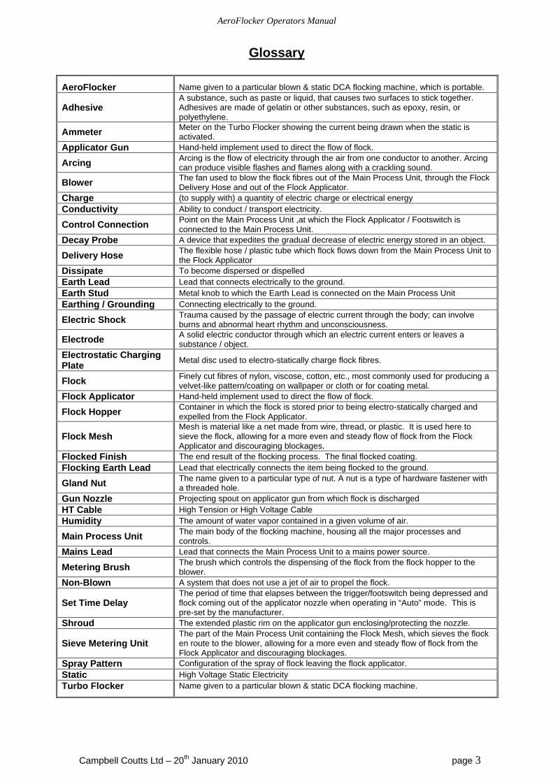
Glossary
AeroFlocker Name given to a particular blown & static DCA flocking machine, which is portable.
Adhesive A substance, such as paste or liquid, that causes two surfaces to stick together. Adhesives are made of gelatin or other substances, such as epoxy, resin, or polyethylene.
Ammeter Meter on the Turbo Flocker showing the current being drawn when the static is activated.
Applicator Gun Hand-held implement used to direct the flow of flock.
Arcing Arcing is the flow of electricity through the air from one conductor to another. Arcing can produce visible flashes and flames along with a crackling sound.
Blower The fan used to blow the flock fibres out of the Main Process Unit, through the Flock Delivery Hose and out of the Flock Applicator.
Charge (to supply with) a quantity of electric charge or electrical energy Conductivity Ability to conduct / transport electricity.
Control Connection Point on the Main Process Unit ,at which the Flock Applicator / Footswitch is connected to the Main Process Unit.
Decay Probe A device that expedites the gradual decrease of electric energy stored in an object.
Delivery Hose The flexible hose / plastic tube which flock flows down from the Main Process Unit to the Flock Applicator
Dissipate To become dispersed or dispelled Earth Lead Lead that connects electrically to the ground. Earth Stud Metal knob to which the Earth Lead is connected on the Main Process Unit Earthing / Grounding Connecting electrically to the ground.
Electric Shock Trauma caused by the passage of electric current through the body; can involve burns and abnormal heart rhythm and unconsciousness.
Electrode A solid electric conductor through which an electric current enters or leaves a substance / object.
Electrostatic Charging Plate
Metal disc used to electro-statically charge flock fibres.
Flock Finely cut fibres of nylon, viscose, cotton, etc., most commonly used for producing a velvet-like pattern/coating on wallpaper or cloth or for coating metal.
Flock Applicator Hand-held implement used to direct the flow of flock.
Flock Hopper Container in which the flock is stored prior to being electro-statically charged and expelled from the Flock Applicator.
Flock Mesh Mesh is material like a net made from wire, thread, or plastic. It is used here to sieve the flock, allowing for a more even and steady flow of flock from the Flock Applicator and discouraging blockages.
Flocked Finish The end result of the flocking process. The final flocked coating. Flocking Earth Lead Lead that electrically connects the item being flocked to the ground.
Gland Nut The name given to a particular type of nut. A nut is a type of hardware fastener with a threaded hole.
Gun Nozzle Projecting spout on applicator gun from which flock is discharged HT Cable High Tension or High Voltage Cable Humidity The amount of water vapor contained in a given volume of air.
Main Process Unit The main body of the flocking machine, housing all the major processes and controls.
Mains Lead Lead that connects the Main Process Unit to a mains power source.
Metering Brush The brush which controls the dispensing of the flock from the flock hopper to the blower.
Non-Blown A system that does not use a jet of air to propel the flock.
Set Time Delay The period of time that elapses between the trigger/footswitch being depressed and flock coming out of the applicator nozzle when operating in “Auto” mode. This is pre-set by the manufacturer.
Shroud The extended plastic rim on the applicator gun enclosing/protecting the nozzle.
Sieve Metering Unit The part of the Main Process Unit containing the Flock Mesh, which sieves the flock en route to the blower, allowing for a more even and steady flow of flock from the Flock Applicator and discouraging blockages.
Spray Pattern Configuration of the spray of flock leaving the flock applicator. Static High Voltage Static Electricity Turbo Flocker Name given to a particular blown & static DCA flocking machine.

AeroFlocker Operators Manual
Campbell Coutts Ltd – 20th January 2010 page 4
Checking the Package Contents Make sure you have received the following items in the package. If any of these items are missing or damaged, please contact Campbell Coutts Ltd. Manual Main Process Unit Mains Lead Flock Delivery Hose Applicator Gun Footswitch Flocking Earth Wire 2 Flock Meshes (one fine, one coarse)
Blower Speed Controls Brush speed Controls
Static Controls
Mains Switch
Flock Hopper
Flocking Earth Wire
Mains / Power lead
Flock Meshes Applicator Gun Flock Delivery Hose
Footswitch
AeroFlocker Operators Manual
Campbell Coutts Ltd – 20th January 2010 page 5
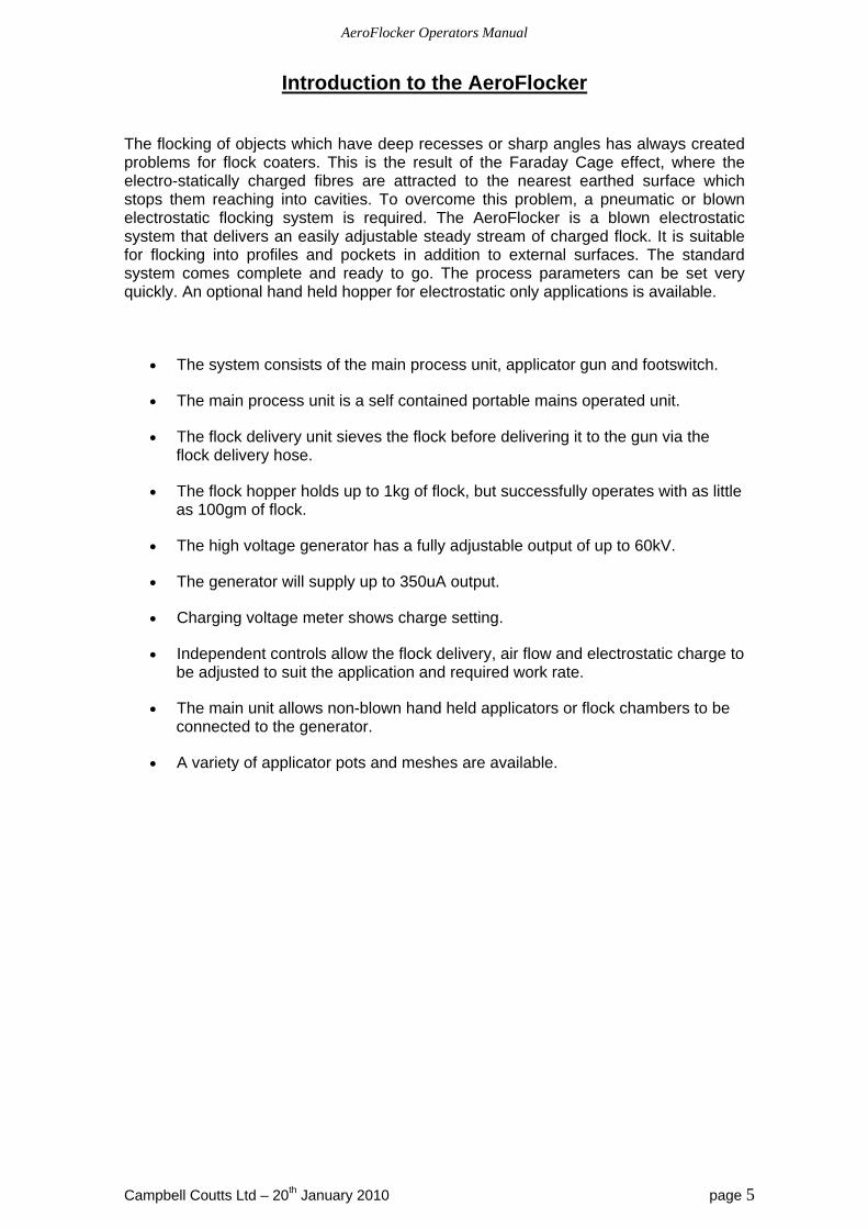
Introduction to the AeroFlocker The flocking of objects which have deep recesses or sharp angles has always created problems for flock coaters. This is the result of the Faraday Cage effect, where the electro-statically charged fibres are attracted to the nearest earthed surface which stops them reaching into cavities. To overcome this problem, a pneumatic or blown electrostatic flocking system is required. The AeroFlocker is a blown electrostatic system that delivers an easily adjustable steady stream of charged flock. It is suitable for flocking into profiles and pockets in addition to external surfaces. The standard system comes complete and ready to go. The process parameters can be set very quickly. An optional hand held hopper for electrostatic only applications is available.
The system consists of the main process unit, applicator gun and footswitch.
The main process unit is a self contained portable mains operated unit.
The flock delivery unit sieves the flock before delivering it to the gun via the flock delivery hose.
The flock hopper holds up to 1kg of flock, but successfully operates with as little as 100gm of flock.
The high voltage generator has a fully adjustable output of up to 60kV.
The generator will supply up to 350uA output.
Charging voltage meter shows charge setting.
Independent controls allow the flock delivery, air flow and electrostatic charge to be adjusted to suit the application and required work rate.
The main unit allows non-blown hand held applicators or flock chambers to be connected to the generator.
A variety of applicator pots and meshes are available.
AeroFlocker Operators Manual
Campbell Coutts Ltd – 20th January 2010 page 6
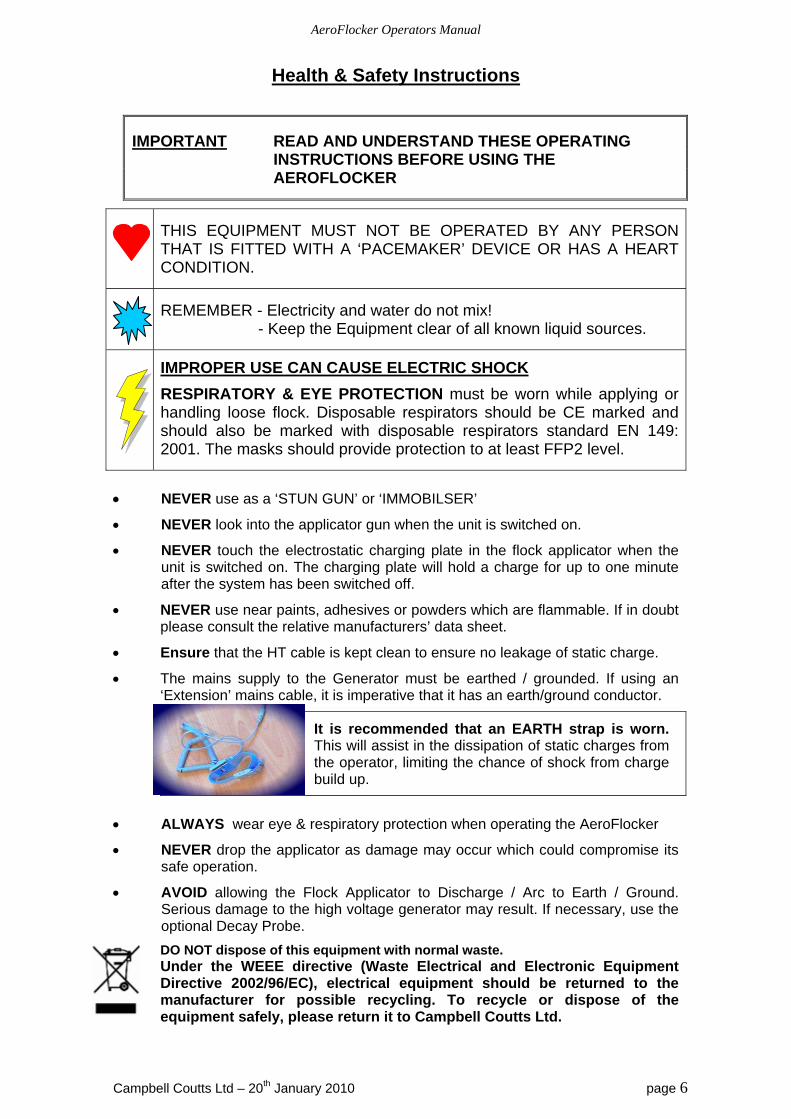
Health & Safety Instructions
IMPORTANT READ AND UNDERSTAND THESE OPERATING INSTRUCTIONS BEFORE USING THE AEROFLOCKER
THIS EQUIPMENT MUST NOT BE OPERATED BY ANY PERSON THAT IS FITTED WITH A ‘PACEMAKER’ DEVICE OR HAS A HEART CONDITION.
REMEMBER - Electricity and water do not mix! - Keep the Equipment clear of all known liquid sources.
IMPROPER USE CAN CAUSE ELECTRIC SHOCK
RESPIRATORY & EYE PROTECTION must be worn while applying or handling loose flock. Disposable respirators should be CE marked and should also be marked with disposable respirators standard EN 149: 2001. The masks should provide protection to at least FFP2 level.
NEVER use as a ‘STUN GUN’ or ‘IMMOBILSER’
NEVER look into the applicator gun when the unit is switched on.
NEVER touch the electrostatic charging plate in the flock applicator when the unit is switched on. The charging plate will hold a charge for up to one minute after the system has been switched off.
NEVER use near paints, adhesives or powders which are flammable. If in doubt please consult the relative manufacturers’ data sheet.
Ensure that the HT cable is kept clean to ensure no leakage of static charge.
The mains supply to the Generator must be earthed / grounded. If using an ‘Extension’ mains cable, it is imperative that it has an earth/ground conductor.
It is recommended that an EARTH strap is worn. This will assist in the dissipation of static charges from the operator, limiting the chance of shock from charge build up.
ALWAYS wear eye & respiratory protection when operating the AeroFlocker
NEVER drop the applicator as damage may occur which could compromise its safe operation.
AVOID allowing the Flock Applicator to Discharge / Arc to Earth / Ground. Serious damage to the high voltage generator may result. If necessary, use the optional Decay Probe.
DO NOT dispose of this equipment with normal waste. Under the WEEE directive (Waste Electrical and Electronic Equipment Directive 2002/96/EC), electrical equipment should be returned to the manufacturer for possible recycling. To recycle or dispose of the equipment safely, please return it to Campbell Coutts Ltd.

AeroFlocker Operators Manual
Campbell Coutts Ltd – 20th January 2010 page 7
The Control Panel
1. Volt Meter –
Displays voltage being supplied to the applicator gun / flock applicator. The meter will only register voltage being supplied when the static is activated via the gun trigger/foot pedal.
2. Mains power switch and Fuse –
There are 2 positions the Mains Power Switch can be set to, either “Off” or “On”. The fuse indicator light will light up when there is mains power being supplied to the AeroFlocker Unit. If the Mains Power Switch is set to “On” and the light is not on, the fuse should be checked, in case it has blown.
1. kV Meter displays voltage output when generator is running.
3. Static Controls 5. Brush Speed
Controls
4. Blower Speed Controls
7. Flock Hopper 6. Flock Brush 2. Mains Power
Switch & Fuse
AeroFlocker Operators Manual
Campbell Coutts Ltd – 20th January 2010 page 8
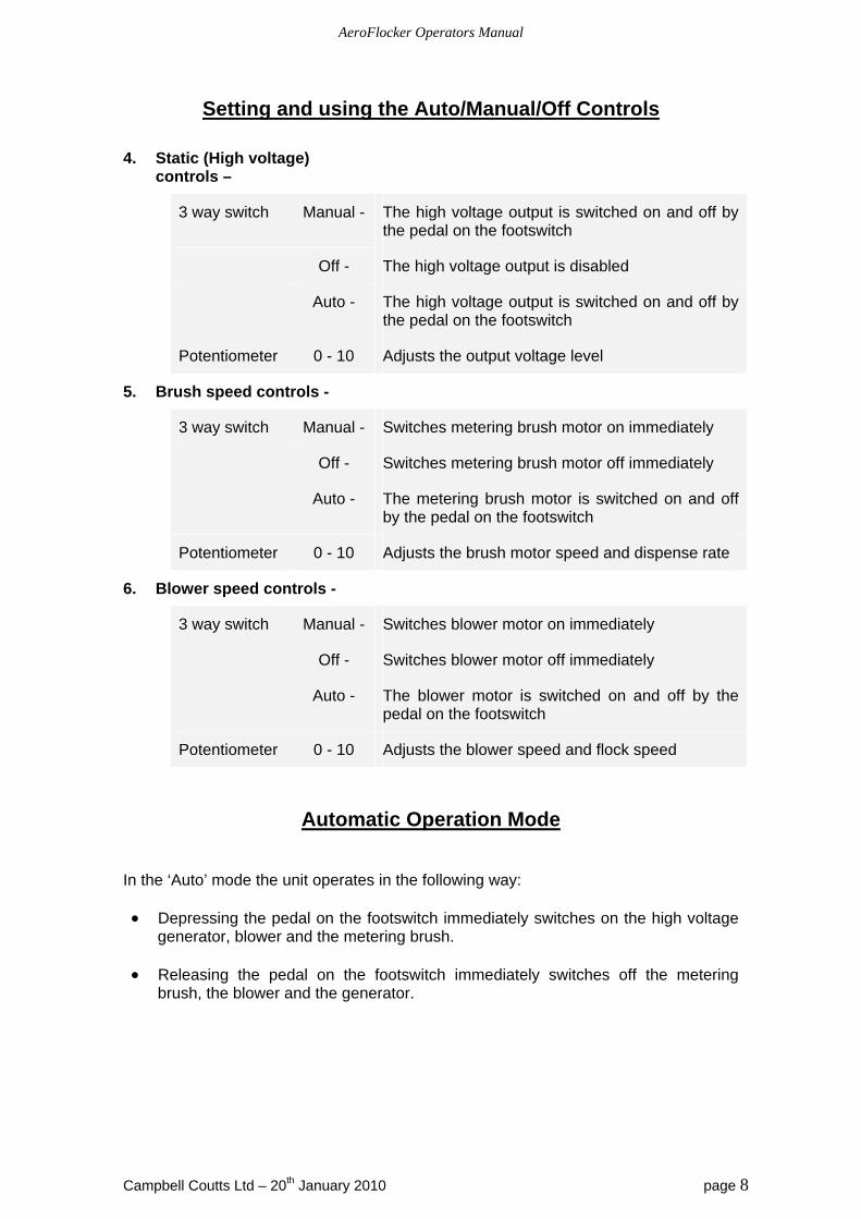
Setting and using the Auto/Manual/Off Controls
4. Static (High voltage) controls –
3 way switch Manual - The high voltage output is switched on and off by the pedal on the footswitch
Off - The high voltage output is disabled
Auto - The high voltage output is switched on and off by the pedal on the footswitch
Potentiometer 0 - 10 Adjusts the output voltage level
5. Brush speed controls -
3 way switch Manual - Switches metering brush motor on immediately
Off - Switches metering brush motor off immediately
Auto - The metering brush motor is switched on and off by the pedal on the footswitch
Potentiometer 0 - 10 Adjusts the brush motor speed and dispense rate
6. Blower speed controls -
3 way switch Manual - Switches blower motor on immediately
Off - Switches blower motor off immediately
Auto - The blower motor is switched on and off by the pedal on the footswitch
Potentiometer 0 - 10 Adjusts the blower speed and flock speed
Automatic Operation Mode In the ‘Auto’ mode the unit operates in the following way:
Depressing the pedal on the footswitch immediately switches on the high voltage generator, blower and the metering brush.
Releasing the pedal on the footswitch immediately switches off the metering brush, the blower and the generator.
AeroFlocker Operators Manual
Campbell Coutts Ltd – 20th January 2010 page 9
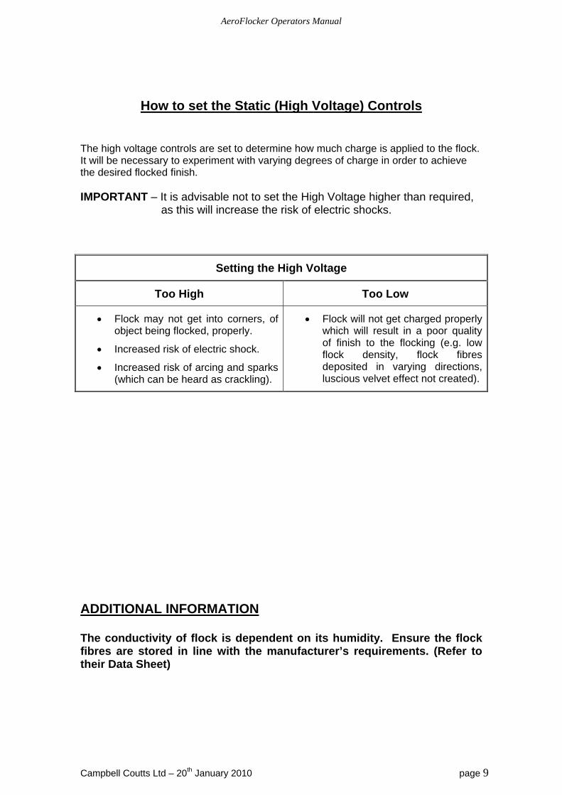
How to set the Static (High Voltage) Controls
The high voltage controls are set to determine how much charge is applied to the flock. It will be necessary to experiment with varying degrees of charge in order to achieve the desired flocked finish. IMPORTANT – It is advisable not to set the High Voltage higher than required,
as this will increase the risk of electric shocks.
Setting the High Voltage
Too High Too Low
Flock may not get into corners, of object being flocked, properly.
Increased risk of electric shock.
Increased risk of arcing and sparks (which can be heard as crackling).
Flock will not get charged properly which will result in a poor quality of finish to the flocking (e.g. low flock density, flock fibres deposited in varying directions, luscious velvet effect not created).
ADDITIONAL INFORMATION The conductivity of flock is dependent on its humidity. Ensure the flock fibres are stored in line with the manufacturer’s requirements. (Refer to their Data Sheet)
AeroFlocker Operators Manual
Campbell Coutts Ltd – 20th January 2010 page 10
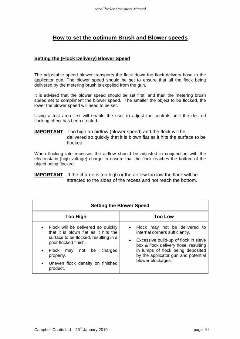
How to set the optimum Brush and Blower speeds
Setting the (Flock Delivery) Blower Speed The adjustable speed blower transports the flock down the flock delivery hose to the applicator gun. The blower speed should be set to ensure that all the flock being delivered by the metering brush is expelled from the gun. It is advised that the blower speed should be set first, and then the metering brush speed set to compliment the blower speed. The smaller the object to be flocked, the lower the blower speed will need to be set. Using a test area first will enable the user to adjust the controls until the desired flocking effect has been created. IMPORTANT - Too high an airflow (blower speed) and the flock will be
delivered so quickly that it is blown flat as it hits the surface to be flocked.
When flocking into recesses the airflow should be adjusted in conjunction with the electrostatic (high voltage) charge to ensure that the flock reaches the bottom of the object being flocked. IMPORTANT - If the charge is too high or the airflow too low the flock will be attracted to the sides of the recess and not reach the bottom.
Setting the Blower Speed
Too High Too Low
Flock will be delivered so quickly that it is blown flat as it hits the surface to be flocked, resulting in a poor flocked finish.
Flock may not be charged properly.
Uneven flock density on finished product.
Flock may not be delivered to internal corners sufficiently.
Excessive build-up of flock in sieve box & flock delivery hose, resulting in lumps of flock being deposited by the applicator gun and potential blower blockages.
AeroFlocker Operators Manual
Campbell Coutts Ltd – 20th January 2010 page 11
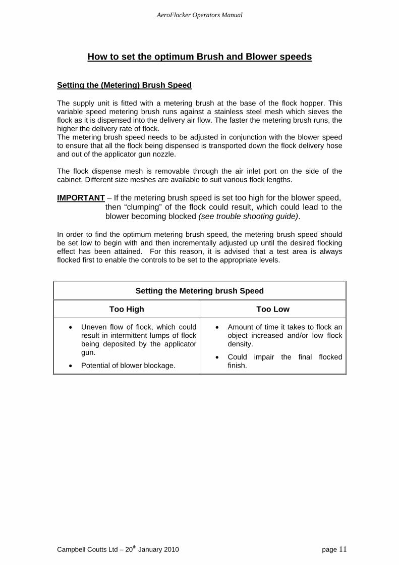
How to set the optimum Brush and Blower speeds Setting the (Metering) Brush Speed The supply unit is fitted with a metering brush at the base of the flock hopper. This variable speed metering brush runs against a stainless steel mesh which sieves the flock as it is dispensed into the delivery air flow. The faster the metering brush runs, the higher the delivery rate of flock. The metering brush speed needs to be adjusted in conjunction with the blower speed to ensure that all the flock being dispensed is transported down the flock delivery hose and out of the applicator gun nozzle. The flock dispense mesh is removable through the air inlet port on the side of the cabinet. Different size meshes are available to suit various flock lengths. IMPORTANT – If the metering brush speed is set too high for the blower speed,
then “clumping” of the flock could result, which could lead to the blower becoming blocked (see trouble shooting guide).
In order to find the optimum metering brush speed, the metering brush speed should be set low to begin with and then incrementally adjusted up until the desired flocking effect has been attained. For this reason, it is advised that a test area is always flocked first to enable the controls to be set to the appropriate levels.
Setting the Metering brush Speed
Too High Too Low
Uneven flow of flock, which could result in intermittent lumps of flock being deposited by the applicator gun.
Potential of blower blockage.
Amount of time it takes to flock an object increased and/or low flock density.
Could impair the final flocked finish.
AeroFlocker Operators Manual
Campbell Coutts Ltd – 20th January 2010 page 12
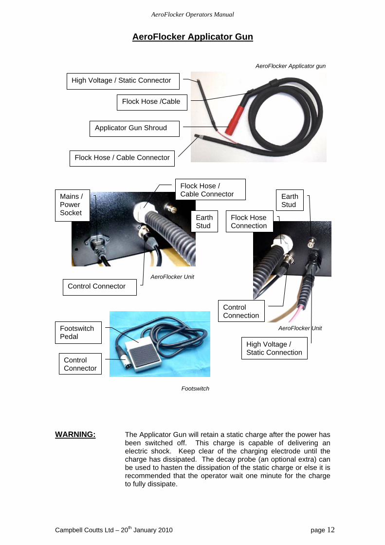
AeroFlocker Applicator Gun
AeroFlocker Applicator gun
AeroFlocker Unit AeroFlocker Unit Footswitch
WARNING: The Applicator Gun will retain a static charge after the power has
been switched off. This charge is capable of delivering an electric shock. Keep clear of the charging electrode until the charge has dissipated. The decay probe (an optional extra) can be used to hasten the dissipation of the static charge or else it is recommended that the operator wait one minute for the charge to fully dissipate.
High Voltage / Static Connector
Applicator Gun Shroud
Flock Hose /Cable
Flock Hose / Cable Connector
Footswitch Pedal
Control Connector
Mains / Power Socket
Flock Hose / Cable Connector
Control Connector
Earth Stud
Earth Stud
Flock Hose Connection
Control Connection
High Voltage / Static Connection
AeroFlocker Operators Manual
Campbell Coutts Ltd – 20th January 2010 page 13
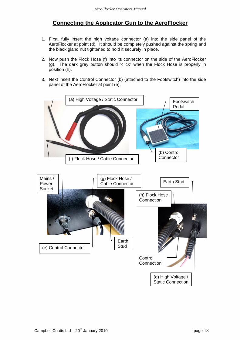
Connecting the Applicator Gun to the AeroFlocker
1. First, fully insert the high voltage connector (a) into the side panel of the AeroFlocker at point (d). It should be completely pushed against the spring and the black gland nut tightened to hold it securely in place.
2. Now push the Flock Hose (f) into its connector on the side of the AeroFlocker (g). The dark grey button should “click” when the Flock Hose is properly in position (h).
3. Next insert the Control Connector (b) (attached to the Footswitch) into the side panel of the AeroFlocker at point (e).
Control Connection
Earth Stud
(h) Flock Hose Connection
(d) High Voltage / Static Connection
(f) Flock Hose / Cable Connector
Footswitch Pedal
(b) Control Connector
(a) High Voltage / Static Connector
Mains / Power Socket
(g) Flock Hose / Cable Connector
(e) Control Connector
Earth Stud
AeroFlocker Operators Manual
Campbell Coutts Ltd – 20th January 2010 page 14
Filling the AeroFlocker with Flock
1. Ensure the mains switch is set to the “Off” position.
2. Open the hinged, clear, polycarbonate lid at the top of the AeroFlocker.
3. Pour in the flock to be used. A minimum of 100gm up to a maximum of 1000gm can be used at any one time.
4. Close the lid.
Changing or emptying the flock
1. Ensure the mains switch is set to the “Off” position.
2. Open the hinged, clear, polycarbonate lid at the top of the Aeroflocker.
3. Scoop out the bulk of the residual flock left in the hopper of the AeroFlocker.
4. Any flock still remaining in the AeroFlocker will need to be discharged to prevent cross-contamination. Set the mains switch to the “On” position.
5. Point the gun into a flocking cabinet, bin bag or some other repository for the residual flock.
6. Switch the blower to manual and set it to maximum.
7. Switch the metering brush to manual and set it to maximum.
8. Switch the static to the “Off” position.
9. Once the flow of flock from the applicator gun has stopped, turn off the AeroFlocker.
10. Using a vacuum cleaner suck the remaining flock from the flock hopper (lift the lid to access this).
11. Use the vacuum cleaner to suck any residual flock from the metering brush, then use it to suck any residual flock left in the flock hose (hold the vacuum to the end of the applicator gun in order to suck the remaining flock from the hose).
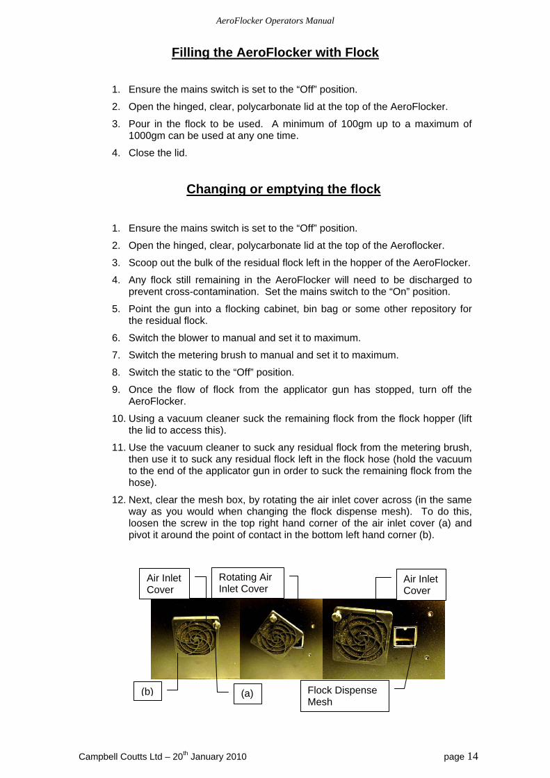
12. Next, clear the mesh box, by rotating the air inlet cover across (in the same way as you would when changing the flock dispense mesh). To do this, loosen the screw in the top right hand corner of the air inlet cover (a) and pivot it around the point of contact in the bottom left hand corner (b).
Air Inlet Cover
Rotating Air Inlet Cover
Air Inlet Cover
Flock Dispense Mesh
(b) (a)

AeroFlocker Operators Manual
Campbell Coutts Ltd – 20th January 2010 page 15
13. Pull out the Flock Dispensing Mesh completely and clean any flock from it.
14. Place the vacuum cleaner nozzle to the hole left by the Flock Dispensing Mesh and suck out any flock from inside the AeroFlocker.
15. Replace the Flock Dispensing Mesh and rotate the Air Inlet Cover back into position and secure.
16. The new flock can now be placed in the flock hopper, as described on the previous page (Filling the AeroFlocker with Flock).
Air Inlet Cover
Flock Dispensing Mesh
Completely remove Flock Dispensing Mesh
AeroFlocker Operators Manual
Campbell Coutts Ltd – 20th January 2010 page 16
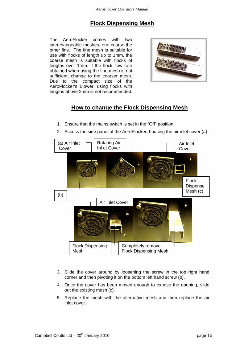
Flock Dispensing Mesh
The AeroFlocker comes with two interchangeable meshes, one coarse the other fine. The fine mesh is suitable for use with flocks of length up to 1mm, the coarse mesh is suitable with flocks of lengths over 1mm. If the flock flow rate obtained when using the fine mesh is not sufficient, change to the coarser mesh. Due to the compact size of the AeroFlocker’s Blower, using flocks with lengths above 2mm is not recommended.
How to change the Flock Dispensing Mesh
1. Ensure that the mains switch is set in the “Off” position.
2. Access the side panel of the AeroFlocker, housing the air inlet cover (a).
3. Slide the cover around by loosening the screw in the top right hand corner and then pivoting it on the bottom left hand screw (b).
4. Once the cover has been moved enough to expose the opening, slide out the existing mesh (c).
5. Replace the mesh with the alternative mesh and then replace the air inlet cover.
(a) Air Inlet Cover
Air Inlet Cover
Flock Dispense Mesh (c)
Rotating Air Inl et Cover
(b)
Air Inlet Cover
Flock Dispensing Mesh
Completely remove Flock Dispensing Mesh

AeroFlocker Operators Manual
Campbell Coutts Ltd – 20th January 2010 page 17
AeroFlocker Operating Instructions
NB As part of correct production management procedures all
operators must be drilled in the safe operation of this equipment.
1. Ensure mains switch is set to the “OFF” position (until otherwise instructed).
2. Prepare the area where the flocking is to be carried out. Ensure that the appropriate safety clothing and equipment is being used.
3. Connect the applicator gun and the footswitch to the AeroFlocker, following the instructions from page 13 of this manual. Connect the Flocking Earth Wire to Earth Stud on the AeroFlocker. Do this by removing the nut from the Earth Stud, placing the ring (from one end of the Flocking Earth Wire) over the Earth Stud and replacing and tightening the nut.
Ring
Crocodile Clip
Flocking Earth Wire
4. Check that the correct flock dispensing mesh is fitted, see page 16 for instructions on how to change the mesh if required. The fine mesh should be used for flock of up to 1mm in length and for anything over 1mm (but no more than 2mm) the coarser mesh should be used.
5. Fill the hopper with the flock to be used, following the instructions from page 14 of this manual.
6. Prepare the item(s) to be flocked using a suitable adhesive.
7. Attach the flocking earth wire to the item to be flocked using the crocodile or alligator clip. It is important to ensure a good grounding / earthing of the product to be flocked, without a good earth connection the final flock finish will be impaired. If the item to be flocked is non-conductive, flat and thin (e.g. t-shirt, wallpaper, greetings card, etc) a metal plate can be placed below / behind the object and the crocodile / alligator clip connected to that. For 3-D objects the adhesive should be conductive enough, so that, as long as the flocking earth wire is connected to the adhesive, a sufficient earthing / grounding should have been achieved. A piece of conductive wire may be used to extend the length of the flocking earth wire (simply clip one end to the crocodile clip and attach the other to the item being flocked), a piece of wire can also be used to provide a less intrusive connection.
8. Ensure the earthing / grounding of the adhesive coated article (item to be flocked) is as perfect as possible. If using the adhesive as the conductor, it is especially important to ensure that the adhesive coating is sufficient and that it connects solidly to the earth / grounding wire. Larger (especially non-conductive) objects (e.g. a 2m² piece of wood) may need to have more than one point of earth / grounding attached to them.
Earth Stud

AeroFlocker Operators Manual
Campbell Coutts Ltd – 20th January 2010 page 18
AeroFlocker Operating Instructions
(continued)
WARNING: After the next step the AeroFlocker and the Gun Applicator will energized with electrostatic charges. Ensure that all safety protocol is being adhered to.
9. Set the mains switch to the “ON” position.
10. Switch the High Voltage to either “Auto” or “Manual” (see page 8 for details). Set the High Voltage / Static to the required level (see page 9 of this manual).
11. The AeroFlocker is now ready to flock. To start flocking, point the applicator gun nozzle at the area to be flocked and, if the AeroFlocker is set to “Auto”, depress the footswitch.
12. The applicator gun should be approximately 200-400mm away from the object being flocked.
13. When finished, set the mains switch to “Off”.
WARNING: The Applicator Gun will retain an electrostatic charge for approximately one minute after the AeroFlocker has been switched off. This charge is sufficient to deliver an electric shock. Wait for the charge to fully dissipate before handling.
AeroFlocker Operators Manual
Campbell Coutts Ltd – 20th January 2010 page 19
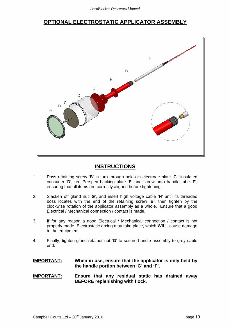
OPTIONAL ELECTROSTATIC APPLICATOR ASSEMBLY
INSTRUCTIONS 1. Pass retaining screw ‘B’ in turn through holes in electrode plate ‘C’, insulated
container ‘D’, red Perspex backing plate ‘E’ and screw onto handle tube ‘F’, ensuring that all items are correctly aligned before tightening.
2. Slacken off gland nut ‘G’, and insert high voltage cable ‘H’ until its threaded
boss locates with the end of the retaining screw ‘B’, then tighten by the clockwise rotation of the applicator assembly as a whole. Ensure that a good Electrical / Mechanical connection / contact is made.
3. If for any reason a good Electrical / Mechanical connection / contact is not
properly made. Electrostatic arcing may take place, which WILL cause damage to the equipment.
4. Finally, tighten gland retainer nut ‘G’ to secure handle assembly to grey cable
end.
IMPORTANT: When in use, ensure that the applicator is only held by the handle portion between ‘G’ and ‘F’.
IMPORTANT: Ensure that any residual static has drained away BEFORE replenishing with flock.
AeroFlocker Operators Manual
Campbell Coutts Ltd – 20th January 2010 page 20
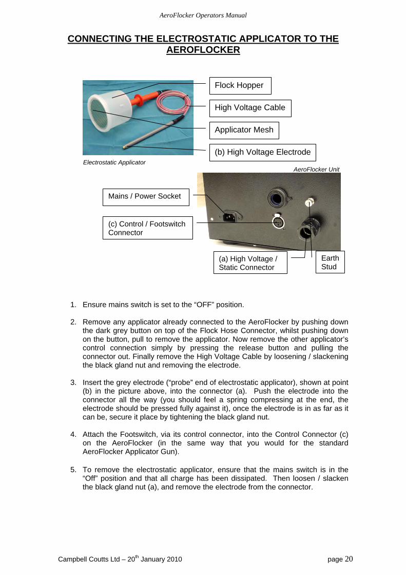
CONNECTING THE ELECTROSTATIC APPLICATOR TO THE AEROFLOCKER
Electrostatic Applicator AeroFlocker Unit
1. Ensure mains switch is set to the “OFF” position.
2. Remove any applicator already connected to the AeroFlocker by pushing down the dark grey button on top of the Flock Hose Connector, whilst pushing down on the button, pull to remove the applicator. Now remove the other applicator’s control connection simply by pressing the release button and pulling the connector out. Finally remove the High Voltage Cable by loosening / slackening the black gland nut and removing the electrode.
3. Insert the grey electrode (“probe” end of electrostatic applicator), shown at point
(b) in the picture above, into the connector (a). Push the electrode into the connector all the way (you should feel a spring compressing at the end, the electrode should be pressed fully against it), once the electrode is in as far as it can be, secure it place by tightening the black gland nut.
4. Attach the Footswitch, via its control connector, into the Control Connector (c)
on the AeroFlocker (in the same way that you would for the standard AeroFlocker Applicator Gun).
5. To remove the electrostatic applicator, ensure that the mains switch is in the
“Off” position and that all charge has been dissipated. Then loosen / slacken the black gland nut (a), and remove the electrode from the connector.
Flock Hopper
(b) High Voltage Electrode
Applicator Mesh
High Voltage Cable
Mains / Power Socket
Earth Stud
(c) Control / Footswitch Connector
(a) High Voltage / Static Connector
AeroFlocker Operators Manual
Campbell Coutts Ltd – 20th January 2010 page 21
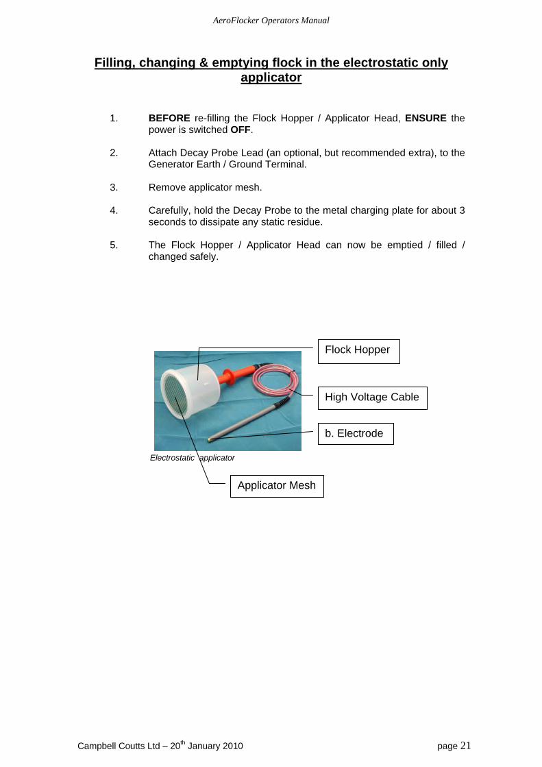
Filling, changing & emptying flock in the electrostatic only applicator
1. BEFORE re-filling the Flock Hopper / Applicator Head, ENSURE the power is switched OFF.
2. Attach Decay Probe Lead (an optional, but recommended extra), to the
Generator Earth / Ground Terminal.
3. Remove applicator mesh. 4. Carefully, hold the Decay Probe to the metal charging plate for about 3
seconds to dissipate any static residue. 5. The Flock Hopper / Applicator Head can now be emptied / filled /
changed safely.
Electrostatic applicator
Flock Hopper
b. Electrode
Applicator Mesh
High Voltage Cable
AeroFlocker Operators Manual
Campbell Coutts Ltd – 20th January 2010 page 22
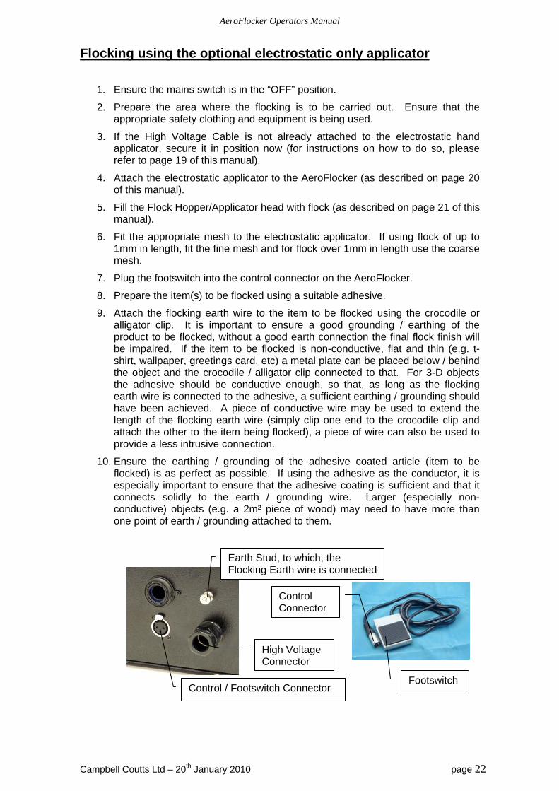
Flocking using the optional electrostatic only applicator
1. Ensure the mains switch is in the “OFF” position.
2. Prepare the area where the flocking is to be carried out. Ensure that the appropriate safety clothing and equipment is being used.
3. If the High Voltage Cable is not already attached to the electrostatic hand applicator, secure it in position now (for instructions on how to do so, please refer to page 19 of this manual).
4. Attach the electrostatic applicator to the AeroFlocker (as described on page 20 of this manual).
5. Fill the Flock Hopper/Applicator head with flock (as described on page 21 of this manual).
6. Fit the appropriate mesh to the electrostatic applicator. If using flock of up to 1mm in length, fit the fine mesh and for flock over 1mm in length use the coarse mesh.
7. Plug the footswitch into the control connector on the AeroFlocker.
8. Prepare the item(s) to be flocked using a suitable adhesive.
9. Attach the flocking earth wire to the item to be flocked using the crocodile or alligator clip. It is important to ensure a good grounding / earthing of the product to be flocked, without a good earth connection the final flock finish will be impaired. If the item to be flocked is non-conductive, flat and thin (e.g. t-shirt, wallpaper, greetings card, etc) a metal plate can be placed below / behind the object and the crocodile / alligator clip connected to that. For 3-D objects the adhesive should be conductive enough, so that, as long as the flocking earth wire is connected to the adhesive, a sufficient earthing / grounding should have been achieved. A piece of conductive wire may be used to extend the length of the flocking earth wire (simply clip one end to the crocodile clip and attach the other to the item being flocked), a piece of wire can also be used to provide a less intrusive connection.
10. Ensure the earthing / grounding of the adhesive coated article (item to be flocked) is as perfect as possible. If using the adhesive as the conductor, it is especially important to ensure that the adhesive coating is sufficient and that it connects solidly to the earth / grounding wire. Larger (especially non-conductive) objects (e.g. a 2m² piece of wood) may need to have more than one point of earth / grounding attached to them.
Footswitch
Earth Stud, to which, the Flocking Earth wire is connected
Control / Footswitch Connector
High Voltage Connector
Control Connector
AeroFlocker Operators Manual
Campbell Coutts Ltd – 20th January 2010 page 23
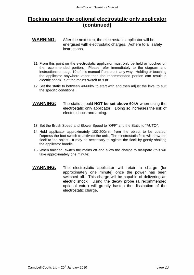
Flocking using the optional electrostatic only applicator (continued)
WARNING: After the next step, the electrostatic applicator will be
energised with electrostatic charges. Adhere to all safety instructions.
11. From this point on the electrostatic applicator must only be held or touched on the recommended portion. Please refer immediately to the diagram and instructions on page 19 of this manual if unsure in any way. Holding or touching the applicator anywhere other than the recommended portion can result in electric shock. Set the mains switch to “On”.
12. Set the static to between 40-60kV to start with and then adjust the level to suit the specific conditions.
WARNING: The static should NOT be set above 60kV when using the electrostatic only applicator. Doing so increases the risk of electric shock and arcing.
13. Set the Brush Speed and Blower Speed to “OFF” and the Static to “AUTO”.
14. Hold applicator approximately 100-200mm from the object to be coated. Depress the foot switch to activate the unit. The electrostatic field will draw the flock to the object. It may be necessary to agitate the flock by gently shaking the applicator handle.
15. When finished, switch the mains off and allow the charge to dissipate (this will take approximately one minute).
WARNING: The electrostatic applicator will retain a charge (for approximately one minute) once the power has been switched off. This charge will be capable of delivering an electric shock. Using the decay probe (a recommended optional extra) will greatly hasten the dissipation of the electrostatic charge.

AeroFlocker Operators Manual
Campbell Coutts Ltd – 20th January 2010 page 24
AEROFLOCKER OPTIONAL EXTRAS
Description Part No.#
Electrostatic only applicator -
175mm Hand applicator with fine
mesh & high voltage cable
Electrostatic only applicator – 4m
high voltage cable
Electrostatic only applicator -
applicator handle
Electrostatic only applicator –
175mm applicator pot
AeroFlocker Operators Manual
Campbell Coutts Ltd – 20th January 2010 page 25
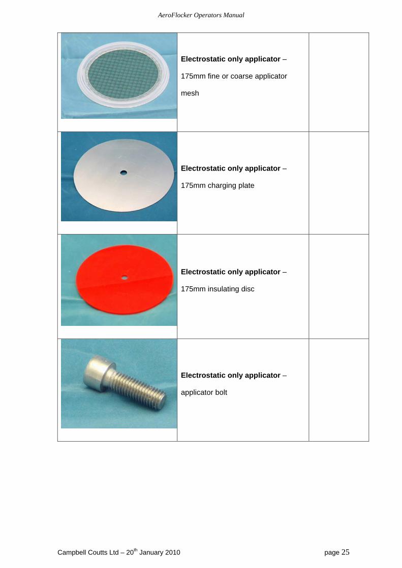
Electrostatic only applicator –
175mm fine or coarse applicator
mesh
Electrostatic only applicator –
175mm charging plate
Electrostatic only applicator –
175mm insulating disc
Electrostatic only applicator –
applicator bolt
AeroFlocker Operators Manual
Campbell Coutts Ltd – 20th January 2010 page 26
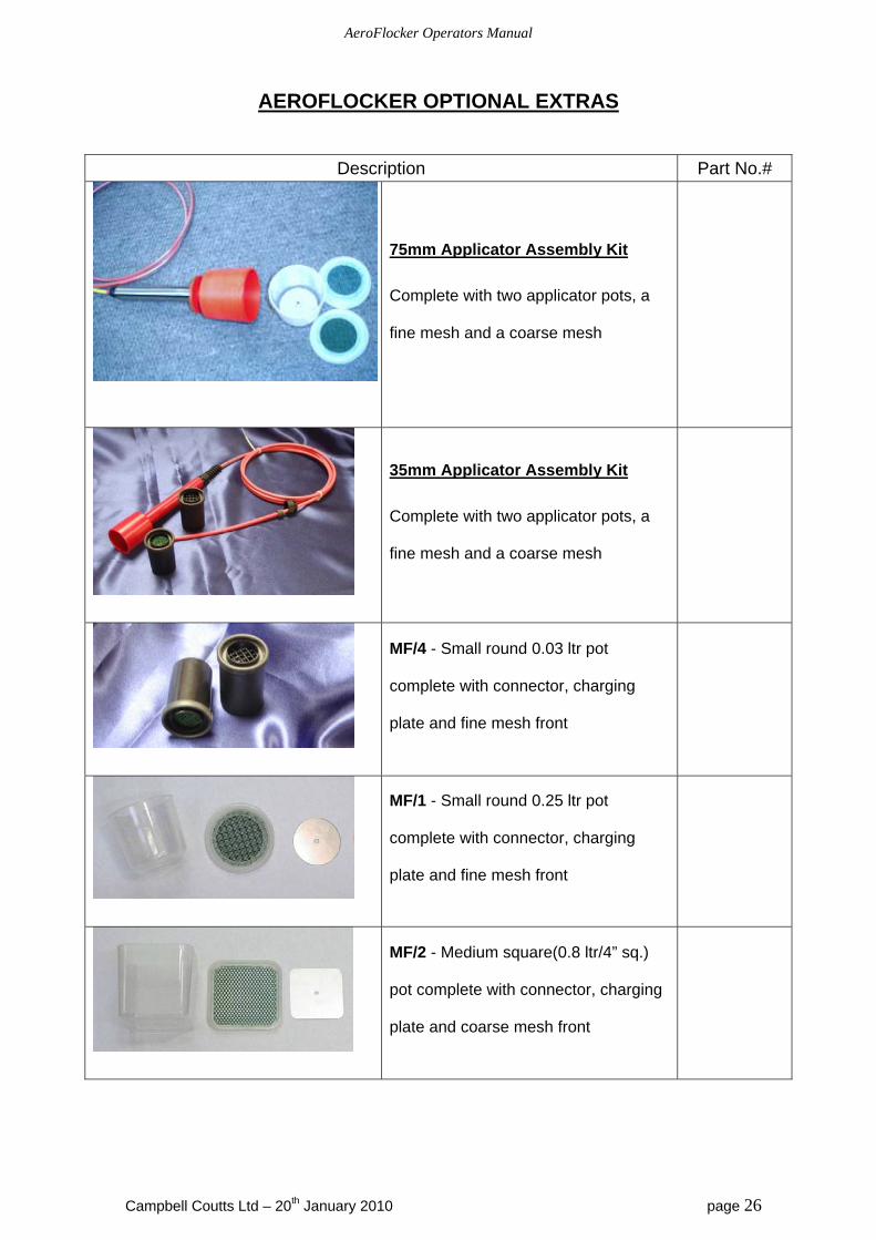
AEROFLOCKER OPTIONAL EXTRAS
Description Part No.#
75mm Applicator Assembly Kit
Complete with two applicator pots, a
fine mesh and a coarse mesh
35mm Applicator Assembly Kit
Complete with two applicator pots, a
fine mesh and a coarse mesh
MF/4 - Small round 0.03 ltr pot
complete with connector, charging
plate and fine mesh front
MF/1 - Small round 0.25 ltr pot
complete with connector, charging
plate and fine mesh front
MF/2 - Medium square(0.8 ltr/4” sq.)
pot complete with connector, charging
plate and coarse mesh front
AeroFlocker Operators Manual
Campbell Coutts Ltd – 20th January 2010 page 27
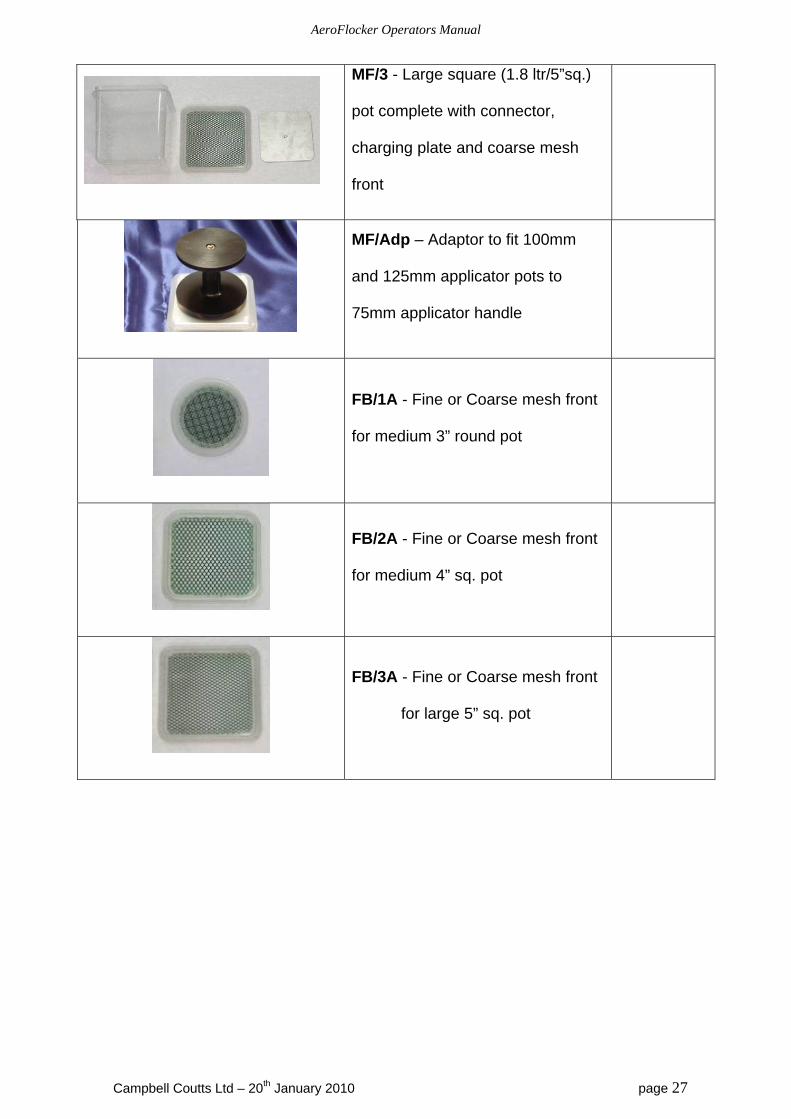
MF/3 - Large square (1.8 ltr/5”sq.)
pot complete with connector,
charging plate and coarse mesh
front
MF/Adp – Adaptor to fit 100mm
and 125mm applicator pots to
75mm applicator handle
FB/1A - Fine or Coarse mesh front
for medium 3” round pot
FB/2A - Fine or Coarse mesh front
for medium 4” sq. pot
FB/3A - Fine or Coarse mesh front
for large 5” sq. pot
AeroFlocker Operators Manual
Campbell Coutts Ltd – 20th January 2010 page 28
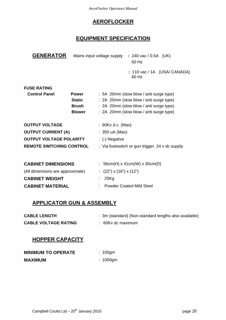
AEROFLOCKER
EQUIPMENT SPECIFICATION
GENERATOR Mains input voltage supply : 240 vac / 0.5A (UK)
50 Hz : 110 vac / 1A (USA/ CANADA) 60 Hz
FUSE RATING
Control Panel Power
Static
Brush
Blower
: 5A 20mm (slow blow / anti surge type)
: 2A 20mm (slow blow / anti surge type)
: 2A 20mm (slow blow / anti surge type)
: 2A 20mm (slow blow / anti surge type)
OUTPUT VOLTAGE : 60Kv d.c. (Max)
OUTPUT CURRENT (A) : 350 uA (Max)
OUTPUT VOLTAGE POLARITY : (-) Negative
REMOTE SWITCHING CONTROL : Via footswitch or gun trigger. 24 v dc supply
CABINET DIMENSIONS : 56cm(H) x 41cm(W) x 30cm(D)
(All dimensions are approximate) : (22”) x (16”) x (12”)
CABINET WEIGHT : 25Kg
CABINET MATERIAL : Powder Coated Mild Steel
APPLICATOR GUN & ASSEMBLY
CABLE LENGTH : 3m (standard) (Non-standard lengths also available)
CABLE VOLTAGE RATING : 60Kv dc maximum
HOPPER CAPACITY
MINIMUM TO OPERATE : 100gm
MAXIMUM : 1000gm
AeroFlocker Operators Manual
Campbell Coutts Ltd – 20th January 2010 page 29
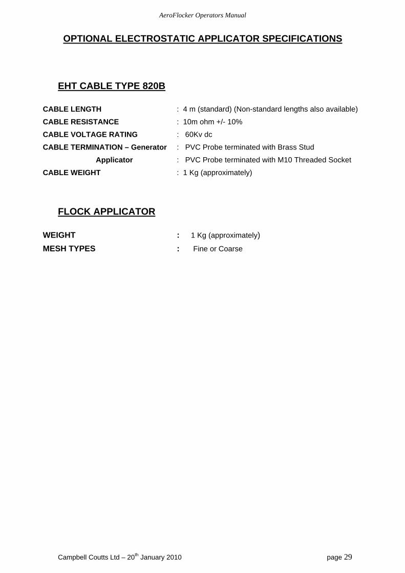
OPTIONAL ELECTROSTATIC APPLICATOR SPECIFICATIONS
EHT CABLE TYPE 820B
CABLE LENGTH : 4 m (standard) (Non-standard lengths also available)
CABLE RESISTANCE : 10m ohm +/- 10%
CABLE VOLTAGE RATING : 60Kv dc
CABLE TERMINATION – Generator : PVC Probe terminated with Brass Stud
Applicator : PVC Probe terminated with M10 Threaded Socket
CABLE WEIGHT : 1 Kg (approximately)
FLOCK APPLICATOR
WEIGHT : 1 Kg (approximately)
MESH TYPES : Fine or Coarse
AeroFlocker Operators Manual
Campbell Coutts Ltd – 20th January 2010 page 30
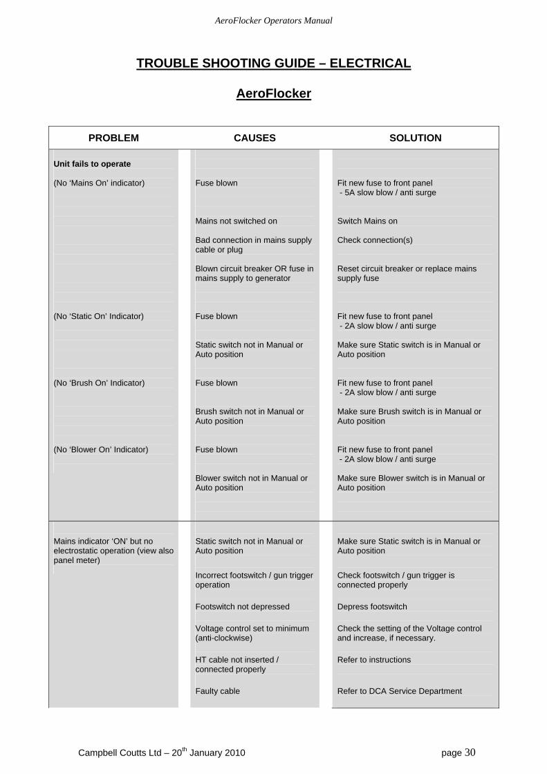
TROUBLE SHOOTING GUIDE – ELECTRICAL
AeroFlocker
PROBLEM CAUSES SOLUTION
Unit fails to operate (No ‘Mains On’ indicator) (No ‘Static On’ Indicator) (No ‘Brush On’ Indicator) (No ‘Blower On’ Indicator)
Fuse blown Mains not switched on Bad connection in mains supply cable or plug Blown circuit breaker OR fuse in mains supply to generator Fuse blown Static switch not in Manual or Auto position Fuse blown Brush switch not in Manual or Auto position Fuse blown Blower switch not in Manual or Auto position
Fit new fuse to front panel - 5A slow blow / anti surge Switch Mains on Check connection(s) Reset circuit breaker or replace mains supply fuse Fit new fuse to front panel - 2A slow blow / anti surge Make sure Static switch is in Manual or Auto position Fit new fuse to front panel - 2A slow blow / anti surge Make sure Brush switch is in Manual or Auto position Fit new fuse to front panel - 2A slow blow / anti surge Make sure Blower switch is in Manual or Auto position
Mains indicator ‘ON’ but no electrostatic operation (view also panel meter)
Static switch not in Manual or Auto position
Incorrect footswitch / gun trigger operation
Footswitch not depressed
Voltage control set to minimum (anti-clockwise)
HT cable not inserted / connected properly
Faulty cable
Make sure Static switch is in Manual or Auto position
Check footswitch / gun trigger is connected properly
Depress footswitch
Check the setting of the Voltage control and increase, if necessary.
Refer to instructions
Refer to DCA Service Department
AeroFlocker Operators Manual
Campbell Coutts Ltd – 20th January 2010 page 31
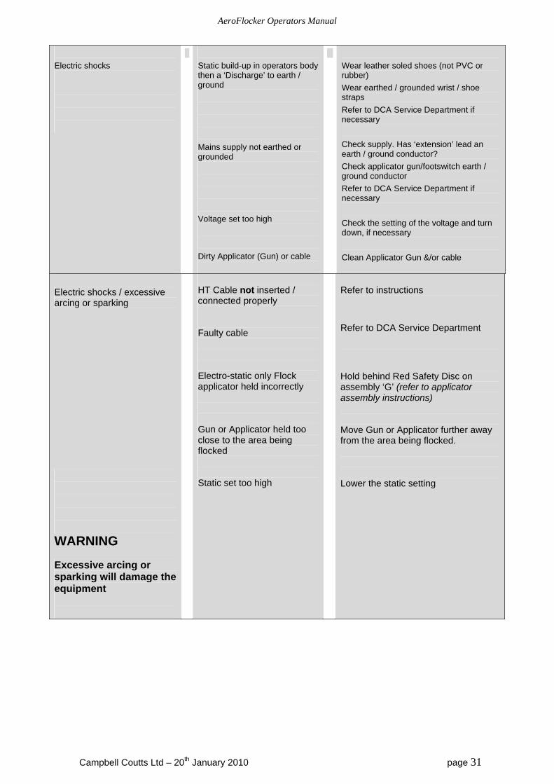
Electric shocks
Static build-up in operators body then a ‘Discharge’ to earth / ground
Mains supply not earthed or grounded
Voltage set too high
Dirty Applicator (Gun) or cable
Wear leather soled shoes (not PVC or rubber)
Wear earthed / grounded wrist / shoe straps
Refer to DCA Service Department if necessary
Check supply. Has ‘extension’ lead an earth / ground conductor?
Check applicator gun/footswitch earth / ground conductor
Refer to DCA Service Department if necessary
Check the setting of the voltage and turn down, if necessary
Clean Applicator Gun &/or cable
Electric shocks / excessive arcing or sparking WARNING Excessive arcing or sparking will damage the equipment
HT Cable not inserted / connected properly Faulty cable Electro-static only Flock applicator held incorrectly Gun or Applicator held too close to the area being flocked Static set too high
Refer to instructions
Refer to DCA Service Department
Hold behind Red Safety Disc on assembly ‘G’ (refer to applicator assembly instructions) Move Gun or Applicator further away from the area being flocked. Lower the static setting
AeroFlocker Operators Manual
Campbell Coutts Ltd – 20th January 2010 page 32
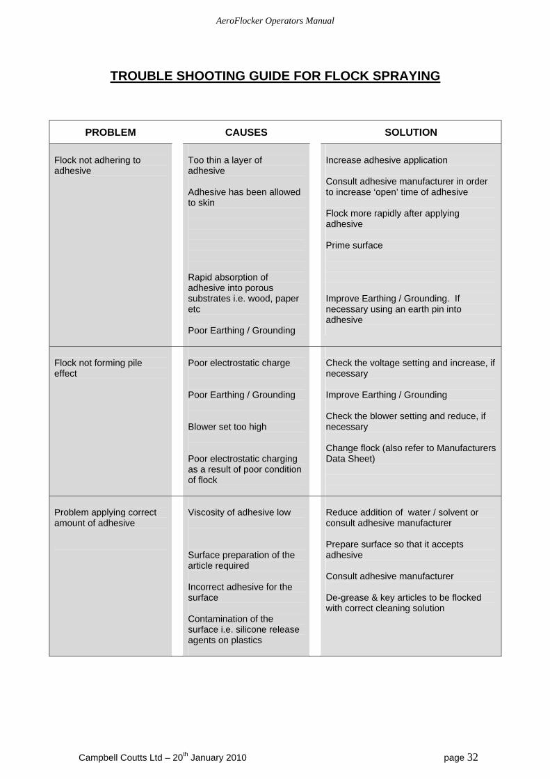
TROUBLE SHOOTING GUIDE FOR FLOCK SPRAYING
PROBLEM CAUSES SOLUTION
Flock not adhering to adhesive
Too thin a layer of adhesive Adhesive has been allowed to skin Rapid absorption of adhesive into porous substrates i.e. wood, paper etc Poor Earthing / Grounding
Increase adhesive application Consult adhesive manufacturer in order to increase ‘open’ time of adhesive Flock more rapidly after applying adhesive Prime surface Improve Earthing / Grounding. If necessary using an earth pin into adhesive
Flock not forming pile effect
Poor electrostatic charge Poor Earthing / Grounding Blower set too high Poor electrostatic charging as a result of poor condition of flock
Check the voltage setting and increase, if necessary Improve Earthing / Grounding Check the blower setting and reduce, if necessary Change flock (also refer to Manufacturers Data Sheet)
Problem applying correct amount of adhesive
Viscosity of adhesive low Surface preparation of the article required Incorrect adhesive for the surface Contamination of the surface i.e. silicone release agents on plastics
Reduce addition of water / solvent or consult adhesive manufacturer Prepare surface so that it accepts adhesive Consult adhesive manufacturer De-grease & key articles to be flocked with correct cleaning solution
AeroFlocker Operators Manual
Campbell Coutts Ltd – 20th January 2010 page 33
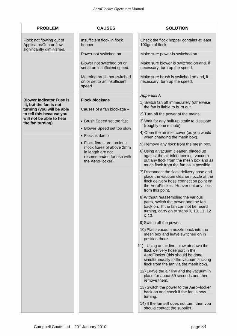
PROBLEM CAUSES SOLUTION
Flock not flowing out of Applicator/Gun or flow significantly diminished.
Insufficient flock in flock hopper Power not switched on Blower not switched on or set at an insufficient speed. Metering brush not switched on or set to an insufficient speed.
Check the flock hopper contains at least 100gm of flock Make sure power is switched on. Make sure blower is switched on and, if necessary, turn up the speed. Make sure brush is switched on and, if necessary, turn up the speed.
Blower Indicator Fuse is lit, but the fan is not turning (you will be able to tell this because you will not be able to hear the fan turning)
Flock blockage Causes of a fan blockage –
Brush Speed set too fast
Blower Speed set too slow
Flock is damp
Flock fibres are too long (flock fibres of above 2mm in length are not recommended for use with the AeroFlocker)
Appendix A
1) Switch fan off immediately (otherwise the fan is liable to burn out.
2) Turn off the power at the mains.
3) Wait for any built up static to dissipate (roughly one minute).
4) Open the air inlet cover (as you would when changing the mesh box).
5) Remove any flock from the mesh box.
6) Using a vacuum cleaner, placed up against the air inlet opening, vacuum out any flock from the mesh box and as much flock from the fan as is possible.
7) Disconnect the flock delivery hose and place the vacuum cleaner nozzle at the flock delivery hose connection point on the AeroFlocker. Hoover out any flock from this point.
8) Without reassembling the various parts, switch the power and the fan back on. If the fan can not be heard turning, carry on to steps 9, 10, 11, 12 & 13.
9) Switch off the power.
10) Place vacuum nozzle back into the mesh box and leave switched on in position there.
11) Using an air line, blow air down the flock delivery hose port in the AeroFlocker (this should be done simultaneously to the vacuum sucking flock from the fan via the mesh box).
12) Leave the air line and the vacuum in place for about 30 seconds and then remove them.
13) Switch the power to the AeroFlocker back on and check if the fan is now turning.
14) If the fan still does not turn, then you should contact the supplier.