
bloc1.pdf
18
Part 1. Deck Machinery, Prime Movers, and Transmissions Part 11. Principles of Hydraulic Power Transmission OFO - Library / MPO - Bibliothèque 111 1203883 4 environnement Canada Canada _ r„---- ■..... ,-. ri e 0 /0 - ' 1 — - 16 -- e la ,P!--- --- . 1.Ap -e "em -Iw o - igrumm ...mar...aree _ _a. ,....---- ,.... ,--xlz , rwi, 0 e • .• 1 ' ----- r U- ,. . • i. , ,. ,,,_.- - .• ...--- - L. .- _ , • • min
-
Upload
alberto-balvin -
Category
Documents
-
view
216 -
download
0
Transcript of bloc1.pdf
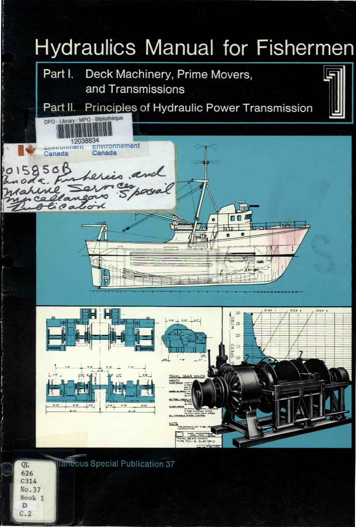
Part 1. Deck Machinery, Prime Movers, and Transmissions
Part 11. Principles of Hydraulic Power Transmission OFO - Library / MPO - Bibliothèque
111 12038834
environnement Canada Canada
_ r„----■..... ,-. ri e 0 /0 - '
1 —
-
16--e la,P!------ .1.Ap-e"em-Iwo-igrumm...mar...aree _ _a. ,....---- ,....
,--xlz, rwi, 0 e •
.• 1
' ----- r U- ,. . • i. , ,. ,,,_.- -
.• ...--- - L..-
_
,
• • min

©Minister of Supply and Services Canada 1978
Available by mail from:Printing and Publishing
Supply and Services CanadaOttawa, Canada K1A OS9or through your bookseller
A deposit copy of this publication is also availablefor reference in public libraries across Canada
Catalog No. Fs 41-31/37-1Canada: $2.00 ISBN 0-660-01834-9
Other countries: $2.40 ISSN 0701-7650
Price subject to change without noticeOttawa
Printed in Canada
by
Friesen PrintersAltona, Manitoba, Canada
Contract No. KF 801-8-0161
Correct citation for this publication: Published by Publié par
Department of Fisheries and the Environment. 1978. Dock .'^ Fisheries and Environment Pêches et Environnementmachinery, prime movers, and transmissions, Pt. I; Canada CanadaPrinciples of hydraulic power transmission, Pt. II, 10 p.In Hydraulics manual for fishermen. Fish, Mar. Serv. Fisheries and Service des pêchesMisc. Publ. 37 (Booklet 1). Marine Service et de la mer
Cover design: Christine Rusk Scientific Information Direction de l'informationand Publications Branch et des publications scientifiques
Ottawa K1A OE6

MISCELLANEOUS SPECIAL PUBLICATION 37
(La version française est en préparation)
Hydraulics Manual for Fishermen1
Booklet
Part I. Deck Machinery, Prime Movers, and Transmissions
Part II. Principles of Hydraulic Power Transmission
Department of Fisheries and the EnvironmentFisheries and Marine ServiceFishermen's Services Branch
Ottawa, Canada K7A OE6
DEPARTMENT OF FISHERIES AND THE ENVIRONMENTFISHERIES AND MARINE SERVICE
Ottawa 1978
leIThis manual is based on a study prepared by Dowty Equipment of
Canada Limited under contract to Fishermen's Services Branch, Fisheriesand Marine Service, Department of Fisheries and the Environment.

NOTICE
The use of proprietary names does not imply endorsement of the product or company. No reference to the Department of Fisheries and the Environment (DFE), or to this publication, shall be made in any advertising or sales promotion which would indicate or imply that DFE approves, recommends, or endorses any proprietary product or proprietary material men-tioned herein, or which has as its purpose an intent to cause directly or indirectly the advertised product to be used or purchased because of this DFE publication.

CONTENTS
FOREWORD V
Part I Deck Machinery, Prime Movers, and Transmissions
1. INTRODUCTION 1
2. MACHINES FOR FISHING BOATS 12.1 Winches 1
2.1.1 Winch power requirements 12.2 Auxiliary Machinery 1
3. PRIME MOVERS 1
4. TRANSMISSIONS 14.1 Need for Efficient Transmission 14.2 Power Transmission Methods 3
4.2.1 Mechanical power transmission 34.2.2 Electrical power transmission 34.2.3 Pneumatic power transmission 34.2.4 Ideal power transmission method 34.2.5 Hydraulic power transmission 4
Part II Principles of Hydraulic Power Transmission
1. INTRODUCTION 4
2. PROPERTIES OF A LIQUID 4
3. How POWER IS TRANSMITTED BY HYDRAULICS 4
4. MEANING OF PRESSURE 5
5. TRANSMISSION OF PRESSURE 5
6. PRINCIPLE OF HYDRAULIC LEVER 5
7. HYDRAULIC JACK 7
7.1 Hydraulic Lever 77.2 Hydraulic Ratchet 77.3 Mechanical Lever 7
8. BASIC HYDRAULIC POWER TRANSMISSION SYSTEM 8
9. HYDRAULIC CIRCUIT 8
10. LIQUID FLOW CHARACTERISTICS 8
11. PRESSURE DROP 8
REFERENCES 10
FIGURES
1 Effects of transmission efficiency on engine load 22 Disadvantages of mechanical transmissions 23 Disadvantages of electric drives 34 Similarity between hydraulic and electric transmissions 55 Meaning of pressure 56 Transmission of pressure 67 Hydraulic and mechanical levers 68 The hydraulic jack, a basic hydraulic system 69 Laminar and turbulent flow patterns 8
10 Useful and wasteful pressure drop 9
lll


FOREWORD
If the fisherman is to achieve a good standard of living he must obtain a good profit from his catch. He has little control over the number of fish available or the demand for his product; his expertise is catching fish. To do this efficiently it is necessary to have good but not necessarily the most expensive equipment. However, the equipment must be safe, efficient, reliable, durable, and economical. Deck machinery helps men handle nets and process fish and this machinery needs a source of power. Because the power must be transmitted, the prime mover and transmission have to be as reliable as the machinery. It is a common opinion that machines and prime movers are reliable but that the weak link is the transmission, particularly when it is hydraulic. There is some justification for this opinion because in the past many mistakes have been made in the design and installation of hydraulic transmissions. However, transmission of power by hydraulics is especially suited to the needs of deck machinery. Properly designed and installed it is safe and dependable, and is good enough for use in large aircraft. But to be successful, a hydraulic transmission must be designed, installed, and maintained by knowledgeable people.
This Manual consists of six separate Booklets. They outline the ideas, materials, and methods used to create a safe, efficient, and reliable hydraulic power transmission. Generally, the discussion of each topic is brief and, no doubt, some points are missed; however, the intention is to help the practical worker understand hydraulics. Although written mainly for mechanics, the Manual should also be of value to system designers and draftsmen because it emphasizes practical require-ments. The mechanic must have some knowledge of the principles behind the design of hydraulic power transmissions, appreciate the great need for cleanliness inside the system, and the necessity to keep the operating temperature at a reason-able level. He should understand how the various components work, and how to carry out necessary troubleshooting and repair procedures. Special knowledge and skill are needed by the hydraulic systems mechanic and this Manual will supply some of that knowledge. Skill will be obtained when he applies this knowledge to his work.
Fishermen's Services Branch Fisheries and Marine Service
Department of Fisheries and the Environment
■■■■

Part I. Deck Machinery, Prime Movers, and Transmissions
1. INTRODUCTION
The fisherman needs machines to help lighten hiswork and improve productivity. When buying a ma-chine he must be concerned about the type, poweravailable to drive it, and how this power is transmittedto the machine. Part I of this Booklet discusses fishingmachinery and related equipment, the type of powergenerators available, and the alternative ways powercan be transmitted to the machines.
requires assistance to open and close heavy doors andmove booms. The winch is often adapted to thesetasks, but an actuator with a push-pull motion of itsshaft could be more suitable. When it can be used,this type of actuator is lighter, more compact, and lessexpensive than a winch. Sometimes a powered con-veyor is needed to move the fish in and out of storage,and most vessels require power-assisted steering sys-tems. These and other machines are useful to thefisherman only if they are dependable and help himmake the maximum profit from his operation.
2. MACHINES FOR FISHING BOATS
2.1 WinchesThe most valuable machines to fishermen are rope
handling machines. The most common is the winchand every commercial fishing boat is fitted with oneor more, with the possible exception of small inshorevessels. Different fishing methods require different winchdesigns, but basically a winch is a drum or reel ontowhich the rope is wound. The drum is supported bybearings that allow it to rotate. Drum size dependson the rope's diameter and length. It is a simple andpractical device but becomes more complex whenbrakes, clutches, smooth-winds, or other auxiliarycomponents are added.
The winch is driven by a motor, and the motorsize depends on the power required. The higher thepower required, the larger the motor, and a largemotor takes up valuable deck space. Most fishing boatshave no space to spare on the working deck where thewinch is usually mounted, so it is important that boththe winch and motor be as compact as possible. Final-ly, winches are generally exposed to the weather andmust be suitable for wet and cold conditions.
2.1.1 Winch Power Requirements Power needed todrive the winch depends on rope pull and the speedit is hauled. In operation, a winch is required to exertlarge tension forces on the rope, but also to move itat low speeds. The combination of high forces at lowspeeds requires large amounts of power. On the largestCanadian trawlers there are winches with power re-quirements up to 400 horsepower (HP), 200 HPwinches are more common, and winches with capacitiesbetween 15 and 50 HP are used extensively. Wincheshaul and store rope and require power continuouslyfor the time it takes to wind the rope onto the drum.On large trawl winches this may take 10 minutes (min)or more; smaller auxiliary winches may only needcontinuous power for periods of a minute or so.
2.2 Auxiliary MachineryIn addition to handling ropes, the crew often
3. PRIME MOVERS
A device that generates power is called a primemover. On a fishing boat, the most common primemover is the diesel engine. All prime movers supplymechanical power by means of a rotating output shaft.The power generated is affected by shaft speed. Primemovers run most efficiently at fixed speeds, and canbest develop their "rated" power and provide a reason-able service life at fixed speeds.
4. TRANSMISSIONS
Generally speaking, the shorter the distance poweris transmitted the more efficient the operation, so it isdesirable to locate the prime mover as close as possibleto the machine. On a fishing boat, however, there areseveral reasons why a prime mover may not be mountednext to the machines it powers. Diesel engines are largeand need protection from the weather. They are un-suitable for mounting on the working deck and otherplaces where space is limited. Therefore, power oftenhas to be transmitted some distance to the machinery.The constant speed of the prime-mover shaft is rarelywhat is needed by the machines. The machinery has itsown range of operating speeds and is started andstopped independently of the prime mover. To accom-plish this a transmission is installed between the primemover and machine. A transmission may be a simpleclutch that allows the machine to be disconnected fromthe prime mover, but normally it is a complex assemblyof components whose purpose is to give the operatoraccurate control of the machine's speed.
4.1 Need for Efficient TranmissionOne law of nature is that no device which trans-
mits power is 100% efficient. In other words, whenpower from a prime mover is transmitted to a machine,some power is used to overcome friction within thetransmission and is lost before it reaches the machine.This lost power is undesirable because: (1) it can cause
1

LOW HEAT (LOW POWER LOSS)
LOW FRICTION
HIGH HEAT (HIGH POWER LOSS)
op•
TRANSMISSION
3 _1
AN INEFFICIENT TRANSMISSION ENGINE MACHINE
îlt EXCESSIVE MAINTENANCE REQUIRED
SPEED OF MACHINE CAN ONLY BE VARIED BY CHANGING ENGINE SPEED WHICH CAUSES WASTE OF FUEL
DRIVE SHAFT, SPROCKETS, & CHAINS USE UP VALUABLE SPACE
rt
OPEN MECHANICAL DRIVES ARE A HAZARD TO CREW
AN EFFICIENT TRANSMISSION
HIGH FRICTION
FIG. 1. Effects of transmission efficiency on engine load
FIG. 2. Disadvantages of mechanical transmissions
2

the transmission to overheat, and (2) power used toovercome friction is not available to drive the machineand is wasted. The prime mover must, therefore,develop enough power to drive the machine and toovercome friction within the transmission (Fig. 1).If transmission losses are low, efficiency is high andlittle heat is generated. The prime mover supplies thepower demanded by the machine, plus the powerrepresented by the losses. If transmission losses arehigh, efficiency is low and much heat is generated.The extra load placed on the prime mover by aninefficient transmission increases fuel consumption,causes increased wear to both the prime mover andtransmission, and decreases their useful life.
4.2 Power Transmission MethodsThe mechanical power generated by a diesel
engine is unsuitable for many ship's needs and otherforms of power are obtained by converting the me-chanical power of the rotating shaft into electric,pneumatic, and hydraulic power as required. Withthese alternative forms of power available, the mostsuitable for transmitting power to the deck machinerymay be chosen.
4.2.1 Mechanical Power Transmission A machinecan only use mechanical power and a prime movergenerates mechanical power. If the machine requiresa fixed-speed drive from the prime mover and is posi-tioned near it, mechanical means of transmitting powerto the machine would be the most effective method. Ifthe prime mover is located some distance from the ma-chine, or if variable machine speed is required, thenthe mechanical power transmission becomes a lesssuitable method. Belts, chains, and shafts that transmitpower over long distances occupy a great deal of space,and open drives must be provided with proper guards.If guards are neglected the driveline becomes a hazardto ship's personnel. Also, open-type drives usuallyrequire more maintenance. Because of these disadvan-tages (Fig. 2), alternative methods of power transmis-sion must be considered.
4.2.2 Electrical Power Transmission Alternatingcurrent (AC) electric power is available on ships forlighting and for navigation and other equipment. Theadvantages of AC electric power are that it can beconveniently transmitted efficiently and economicallyover long distances, and it drives simple and inexpen-sive, constant speed electric motors, which are used formany purposes throughout a ship. However, there aresome disadvantages with electric power transmission.The electric motor must have a special enclosure ifit is to be fitted on deck or in the weather. Thisincreases its size and sharply increases its price. Ifvariable speed is required, direct current (DC) poweris needed and this usually necessitates further power
ELECTRIC MOTOR ISBULKY & NEEDS SPECIALPROTECTION
HYDRAULIC MOTOR ALLOWSMORE WORKING SPACE ANDNEEDS NO SPECIAL PROTECTION
FIG. 3. Disadvantages of electric drives
conversion with expensive and bulky control equip-ment. Electrical power transmission, therefore, is notcompletely suitable for driving deck machinery (Fig. 3).
4.2.3 Pneumatic Power Transmission Compressedair is commonly used on ships. Its big advantage isthat it is not messy and will not contaminate the sur-roundings. Power can be conveniently transmitted overreasonably long distances through piping, and actuatorsdriven by compressed air can be used in hazardous orwet environments without special protection. The maindisadvantage with compressed air as a power trans-mission medium is its compressibility. Because of this,the speed of an air motor or an air cylinder changeswith the load being moved and consequently is verydifficult to control.
4.2.4 Ideal Power Transmission Method From theforegoing discussion, the method ideally suited to thetransmission of power from prime mover to machinehas the following qualities:
1) It is capable of transmitting power efficiently andsafely over distances comparable with the size of thevessel.
2) Actuators that convert the transmitted powerback to mechanical power are capable of operating ondeck and in the weather without special protection.
3) Components in the transmission, particularly theactuators that drive the machines, are small comparedto the amount of power they transmit; i.e. they havea high power-to-weight ratio.
4) The power transmission system is easily con-trolled and suitable for variable speed applications.
5) The power transmitting medium is safe to useand does not contaminate its surroundings.
6) The price is competitive with that of othermethods of power transmission.
3

4.2.5 Hydraulic Power Transmission The transmis-sion of power by hydraulics is capable of meeting all the foregoing requirements. When a hydraulic system is properly designed and installed, power can be piped to any part of the ship. It can be taken around corners easily and safely. Standard hydraulic motors, rotary actuators, and cylinders are suitable for outdoor and wet operations without special protection. A hydraulic motor can work at high pressure and may take up as little as one-sixth the space of an equivalent electric motor or one-tenth that of an air motor. Hydraulic cylinders can supply compact, push–pull movement, and rotary actuators give an oscillating shaft motion.
Comparable electrical actuators are not practical and pneumatic actuators are much larger. Hydraulic power transmissions can be controlled easily and accurately in a number of ways, either at the transmission or from a remote location. Variable speed of the actuator shaft is simple to achieve and control. The power-transmitting medium in a hydraulic system is a liquid which is harmless provided it is kept inside the system, and this can be achieved by good engineering design, and competent installation and maintenance. Finally, a hydraulic power transmission system is usually small-er and less expensive to purchase and install than its competitors.
Part II. Principles of Hydraulic Power Transmission
1. INTRODUCTION
Transmission of power from a prime mover to machinery by means of hydraulics can be efficient, safe, and economical. But what is hydraulics and how does it work? It means that a liquid transmits power. The mechanical link between the prime mover and machine is converted to a hydraulic link, which makes the transmission of power safer and more controllable. In effect, liquid replaces the belts, chains, and shafting that transmit the power mechanically, but to achieve this the liquid must be handled in certain ways. When working with hydraulics it is necessary to know some-thing about the special characteristics of a liquid and the principles that allow practical application.
2. PROPERTIES OF A LIQUID
Liquid is the lifeblood of a hydraulic system and its special characteristics (properties) make it possible for a liquid to transmit power hydraulically.
The most obvious property of a liquid is that it is a fluid and flows easily. This is because the molecules are not bound together as tightly as in a solid and slide past each other with little effort. This same property prevents a liquid from having a shape of its own and allows it to readily take the shape of a con-tainer. A liquid is weak in tension, that is, it cannot be pulled, so to be of use it has to be pushed and must, therefore, be completely contained. Laziness is another important property of a liquid, and it always follows the path of least resistance. If the liquid is contained and can be pushed, it is in a suitable condition to transmit power. It is almost impossible to reduce the volume of liquid, even when high pressure is applied. This important property makes hydraulic transmissions easy to control. Ability to resist a reduction in volume is called "incompressibility" and although very small
changes in volume do occur, for practical purposes these can be neglected.
3. HOW POWER IS TRANSMITTED BY HYDRAULICS
Because liquid is easy to move and difficult to compress it is useful for transmitting power. Liquid conforms to the shape of its container and can be held inside pipes that carry it by the most convenient route from prime mover to machine. Because its volume cannot be reduced, liquid pushed into a pipe at one end will displace the same amount from the other end. What happens at the prime-mover end is repeated at the machine end as if they were connected mechanically. The advantage of the hydraulic linkage is that it takes little space and does not move. Liquid flows inside pipes that can be clamped out of the way, against a ship's structure.
The rotating shaft of a prime mover is not suitable for pushing liquid into a pipe, and it must be coupled to a pump, which can be driven by the prime mover but is specially designed to move liquids. Unlike the centrifugal pump widely used for low-pressure liquid circulating systems, the pump used for hydraulic power transmission is a positive displacement pump. It will push out a definite or fixed quantity of liquid for each revolution of the drive shaft.
If the liquid flowing inside the pipe is to do useful work it must cause some device to move — something that can be driven by the liquid and has an output shaft to drive the machine. Like the pump, it is a positive displacement device and is called the actuator. It can be a cylinder, a motor, or a rotary actuator.
The transmission of power by a liquid consists of three steps. First, the motion of the prime-mover shaft is changed to a flowing liquid by a positive displace-ment pump. Then the liquid is transported through pipes
4

HYDRAULIC PIPING
PRIME
MOVER
1 ' 1 TANK
LIQUID POWER TRANSMISSION
CONTROL
PRIME
MOVERGENERATOR
^GROUND
ELECTRIC POWER TRANSMISSION
FIG. 4. Similarity between hydraulicand electric transmissions
MACHINE
MACHINE
to the actuator. Finally, the actuator converts themotion of liquid into a mechanical movement of anoutput shaft, which is capable of driving a machine.The process can be compared to an electric drivewhere the pump is equivalent to the generator, thepipes are equivalent to the electric wiring, and theactuator does the same thing as an electric motor(Fig. 4).
4. MEANING OF PRESSURE
The only way to move a liquid is to push on it.If there is resistance, the liquid is compressed but thevolume will not be reduced. In this condition the liquidis said to be pressurized. The "pressure" on any fluid(liquid or gas) always means the compressing force.Often it is simply given as pounds (lb) but really meansthe pounds force on each square inch of area support-ing the load and should be given in pounds forceper square inch (psi). In more general terms, pressureis defined as "the force applied to a unit area."
Imagine a tank containing a liquid and fitted witha plunger that slides freely inside the walls, but issealed to prevent leaking. Such an arrangement is sim-ply a cylinder containing a close-fitting piston. Supposethe cross-sectional area of the piston is 10 squareinches (10 in.2) and it supports 500 lb. The liquid isrestrained by the walls of the cylinder and cannotescape past the piston so the liquid must carry theweight. It will not shrink and supports the weight thesame as a solid. The 500-lb weight is supported on10 in.2 of oil under the piston. Each square inch willsupport 50 lb and pressure in the oil is, therefore,50 psi. It is important to remember that the pressuregenerated in the liquid depends only on the load it hasto support and the area of the piston that supports it(Fig. 5).
ELECTRICAL WIRING
PISTON AREA 10 in.2
FIG. 5. Meaning of pressure
Pressure = load = area of pistonpsi = pounds = square inches
5. TRANSMISSION OF PRESSURE
In Fig. 6 a pressure gauge connected into the topof the piston (point A) indicates 50 psi. What pressureis indicated at points B and C? They register the samepressure as gauge A. This is because of another prin-ciple of hydraulics: "when a liquid is pressurized, itexerts the same pressure at all points and in all direc-tions throughout the liquid." This is probably the mostimportant principle of hydraulics, because it showsthat a contained liquid has the ability to transmit forceand power around corners. The principle of pressuretransmission can be taken a step further if we place alarge chamber next to the cylinder, connect them witha pipe, and fill the whole assembly with liquid as shownin Fig. 6. Because nothing has been done to alterconditions other than change the shape of the con-tainer and, because we know that the pressure has thesame value at all points in the liquid, gauges D and Ealso indicate 50 psi. The principle of pressure trans-mission is not affected by liquid depth. It is well knownthat pressure at the bottom of a tank is higher than atthe surface, but this difference can be neglected in ahydraulic system because it is very small in comparisonwith the pressures in the system.
6. PRINCIPLE OF HYDRAULIC LEVER
If the top of the large chamber in Fig. 6 is re-moved and replaced by a piston, the chamber becomesanother hydraulic cylinder (Fig. 7). Imagine that thearea of this large piston is 100 in.2. Then, because
5

500 lb
10
MECHANICAL
LEVER 5000 lb
50 50 psi psi
500 lb
e Ald
lOin
MECHANICAL ADVANTAGE 10:1
AIR VENT ESSENTIAL
50 lb
PUMP CYLINDER 1 In. STROKE
500 lb
OIL RESERVOIR
1
10 in. STROKE
5000 lb
I
FIG. 6. Transmission of pressure
LS. PIVOT
5000 lb
À
HYDRAULIC LEVER
Flo. 7. Hydraulic and mechanical levers
JACK CYLINDER
FIG. 8. The hydraulic jack, a basic hydraulic system
6
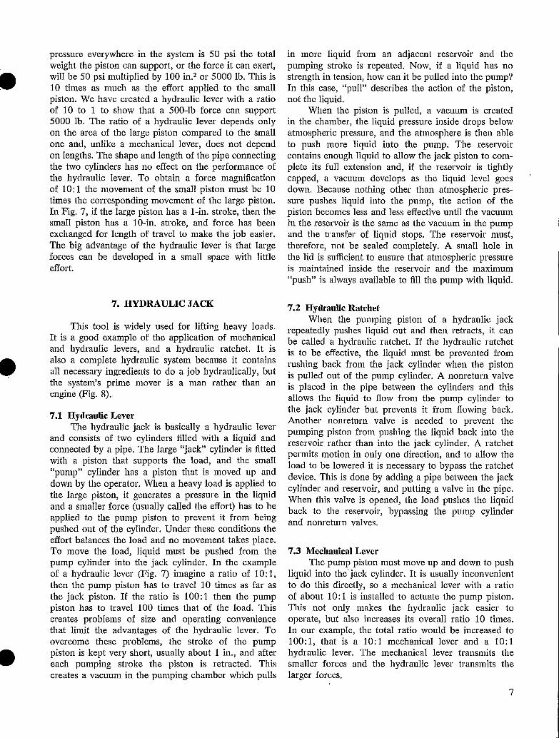
pressure everywhere in the system is 50 psi the totalweight the piston can support, or the force it can exert,will be 50 psi multiplied by 100 in.2 or 5000 lb. This is10 times as much as the effort applied to the smallpiston. We have created a hydraulic lever with a ratioof 10 to 1 to show that a 500-lb force can support5000 lb. The ratio of a hydraulic lever depends onlyon the area of the large piston compared to the smallone and, unlike a mechanical lever, does not dependon lengths. The shape and length of the pipe connectingthe two cylinders has no effect on the performance ofthe hydraulic lever. To obtain a force magnificationof 10:1 the movement of the small piston must be 10times the corresponding movement of the large piston.In Fig. 7, if the large piston has a 1-in. stroke, then thesmall piston has a 10-in. stroke, and force has beenexchanged for length of travel to make the job easier.The big advantage of the hydraulic lever is that largeforces can be developed in a small space with littleeffort.
7. HYDRAULIC JACK
This tool is widely used for lifting heavy loads.It is a good example of the application of mechanicaland hydraulic levers, and a hydraulic ratchet. It isalso a complete hydraulic system because it containsall necessary ingredients to do a job hydraulically, butthe system's prime mover is a man rather than anengine (Fig. 8).
7.1 Hydraulic LeverThe hydraulic jack is basically a hydraulic lever
and consists of two cylinders filled with a liquid andconnected by a pipe. The large "jack" cylinder is fittedwith a piston that supports the load, and the small"pump" cylinder has a piston that is moved up anddown by the operator. When a heavy load is applied tothe large piston, it generates a pressure in the liquidand a smaller force (usually called the effort) has to beapplied to the pump piston to prevent it from beingpushed out of the cylinder. Under these conditions theeffort balances the load and no movement takes place.To move the load, liquid must be pushed from thepump cylinder into the jack cylinder. In the exampleof a hydraulic lever (Fig. 7) imagine a ratio of 10:1,then the pump piston has to travel 10 times as far asthe jack piston. If the ratio is 100:1 then the pumppiston has to travel 100 times that of the load. Thiscreates problems of size and operating conveniencethat limit the advantages of the hydraulic lever. Toovercome these problems, the stroke of the pumppiston is kept very short, usually about. 1 in., and aftereach pumping stroke the piston is retracted. Thiscreates a vacuum in the pumping chamber which pulls
in more liquid from an adjacent reservoir and thepumping stroke is repeated. Now, if a liquid has nostrength in tension, how can it be pulled into the pump?In this case, "pull" describes the action of the piston,not the liquid.
When the piston is pulled, a vacuum is createdin the chamber, the liquid pressure inside drops belowatmospheric pressure, and the atmosphere is then ableto push more liquid into the pump. The reservoircontains enough liquid to allow the jack piston to com-plete its full extension and, if the reservoir is tightlycapped, a vacuum develops as the liquid level goesdown. Because nothing other than atmospheric pres-sure pushes liquid into the pump, the action of thepiston becomes less and less effective until the vacuumin the reservoir is the same as the vacuum in the pumpand the transfer of liquid stops. The reservoir must,therefore, not be sealed completely. A small hole inthe lid is sufficient to ensure that atmospheric pressureis maintained inside the reservoir and the maximum"push" is always available to fill the pump with liquid.
7.2 Hydraulic RatchetWhen the pumping piston of a hydraulic jack
repeatedly pushes liquid out and then retracts, it canbe called a hydraulic ratchet. If the hydraulic ratchetis to be effective, the liquid must be prevented fromrushing back from the jack cylinder when the pistonis pulled out of the pump cylinder. A nonreturn valveis placed in the pipe between the cylinders and thisallows the liquid to flow from the pump cylinder tothe jack cylinder but prevents it from flowing back.Another nonreturn valve is needed to prevent thepumping piston from pushing the liquid back into thereservoir rather than into the jack cylinder. A ratchetpermits motion in only one direction, and to allow theload to be lowered it is necessary to bypass the ratchetdevice. This is done by adding a pipe between the jackcylinder and reservoir, and putting a valve in the pipe.When this valve is opened, the load pushes the liquidback to the reservoir, bypassing the pump cylinderand nonreturn valves.
7.3 Mechanical LeverThe pump piston must move up and down to push
liquid into the'jack cylinder. It is usually inconvenientto do this directly, so a mechanical lever with a ratioof about 10:1 is installed to actuate the pump piston.This not only makes the hydraulic jack easier tooperate, but also increases its overall ratio 10 times.In our example, the total ratio would be increased to100:1, that is a 10:1 mechanical lever and a 10:1hydraulic lever. The mechanical lever transmits thesmaller forces and the hydraulic lever transmits thelarger forces.
7

8. BASIC HYDRAULIC POWER TRANSMISSION returns to the reservoir at low pressure ready to be SYSTEM
The hydraulic jack is a good example of a hydraulic power transmission system because it con-tains the six basic components necessary for all systems. Only one component is liquid, the others are me-chanical components needed to handle the liquid and make the system work.
1) Liquid is the fundamental component of a hy-draulic system.
2) The pump in a hydraulic jack consists of a manually operated pumping piston and two nonreturn valves. Normally the pump is required to supply a continuous flow of liquid and is designed to be driven by the rotating shaft of the prime mover.
3) The actuator is a jack cylinder and piston. It converts liquid motion back into mechanical move-ment, the reverse of what is done by the pump.
4) Controls are necessary to regulate the flow of liquid to and from the actuator if a hydraulic power transmission is to be effective. Control of actuator movement in the hydraulic jack is achieved by the valve which determines whether the jack cylinder will hold, lift, or lower the load simply by being open or closed.
5) The reservoir stores sufficient liquid for full-stroke operation of the actuator, plus that required to fill all components and a reserve supply.
6) Piping connects the pump to the actuator. All hydraulic power transmissions need piping to carry the liquid from one component to the next. Piping is as important to the hydraulic drive as a chain is to a chain drive, or the wires to an electric transmission.
9. HYDRAULIC CIRCUIT
When a hydraulic jack is operated, liquid is taken from storage in the reservoir and transferred to the large jack cylinder where it is stored under pressure. The liquid level in the reservoir decreases and the jack cylinder volume increases. As the load is lowered, the jack cylinder returns the liquid to the reservoir. In most systems, however, power is transmitted con-tinuously and the pump must draw on an unlimited supply of liquid or it soon runs dry. Therefore, the liquid cannot be stored at the actuator as is the case with the hydraulic jack. It must work on the actuator then immediately return to the reservoir. In doing so, it completes a circuit through interconnecting pipes, from reservoir to pump, pump to actuator, and back to the reservoir to provide the pump with all the liquid it needs. The hydraulic circuit is the route the liquid takes when it is drawn from the reservoir, pres-surized and given energy by the engine-driven pump, gives up this pressure energy at the actuator, and
reused.
10. LIQUID FLOW CHARACTERISTICS
A liquid is not frictionless and it always takes some work to make it flow, which means that a pres-sure is required to make it flow. This pressure is small but must be applied to force the liquid's molecules to slide past one another.
Inside a container the liquid tends to cling to the walls and extra force is needed to shear this bond. This friction causes resistance to flow, and a liquid has to be forced through any piping system, even if only to be discharged to the atmosphere. Least resistance is generated if flow is smooth (laminar). In this type of flow the body of liquid slides in layers. The layer attached to the pipe wall is stationary, but the further the layer is away from the wall the faster it flows. However, in a hydraulic system the flow is more likely to be turbulent. The liquid tumbles along the piping bore and the layers are broken up, causing additional resistance. Turbulent flow cannot be eliminated, but it can be reduced by using smooth bore pipe rather than rough bore pipe, and by allowing the liquid to flow at low speed (Fig. 9).
11. PRESSURE DROP
The force, or pressure needed to push the liquid through a circuit depends on the type of flow and number of obstructions. The pressure at the pump discharge is always higher than at the outlet and the pressure is said to drop as the liquid flows toward the exit.
"Pressure drop" means the difference in pressure between any two selected points in a circuit. The greater the pressure drop needed to force the liquid around the circuit, the greater the power wasted and heat gen-erated; but this loss occurs only if the liquid is flowing. If it stops flowing the liquid is then held in a closed
TURBULENT FLOW (UNDESIRABLE)
ZERO SPEED AT PIPE WALL
-= _ _ MAX OIL SPEED AT CENTER OF PIPE
LAMINAR OR STREAMLINED FLOW (DESIRABLE)
FIG. 9. Laminar and turbulent flow patterns
8

container and the pressure will be the same at allpoints. However, the pressure drop from the inlet tooutlet ports of an actuator is not wasteful. It is ameasure of the work done by the liquid in making theshaft of the actuator work. This pressure drop isgenerated by the load on the actuator shaft and existswhether the liquid supply is stationary or flowing. The
USEFUL PRESSURE DROP
two kinds of pressure drop in a hydraulic power trans-mission circuit can be called "useful" and "wasteful,"respectively. If the pressure drop is generated by thesystem's load it is useful, but if it is needed just to over-come the circuit's resistance to flow it is wasteful andshould be as small as practical (Fig. 10).
WASTEFUL PRESSURE DROP
PRESSURE DROPS AS LIQUID FLOWSTHROUGH PIPING
RESISTANCE TO FLOWCAUSED BY PIPING& VALVES
0FiG. 10. Useful and wasteful pressure drop
ATMOSPHERICPRESSUREIF TANKVENTED
1
9

REFERENCES
AEROQUIP CORI'ORATION. 1964. Piping fluid power systems. Bull. 770: 18 p. 1970. Guide for routing and installation of flexible hose assemblies. Bull. 5075:
P. 1971. Piping leaks, causes and cures. Bull. 5026A: 12 p. 1972. Trouble-shooting hydraulic systems. Bull. 5215: 3 p.
CATERPILLAR TRACTOR COMPANY. 1970. Reservoir design for mobile equipment hydrau-lic circuits. SAE Sept. meeting. Milwaukee, Wis. Pap. 700722.
DETROIT COIL COMPANY. Undated. What is a solenoid? Ferndale, Mich. Bull. 6 p. DOWTY HYDRAULIC UNITS , 1970. Modern high performance gear pumps. Cheltenham,
U.K. 24 p.
ENVIRONMENT CANADA. 1971. Hydraulics for small trawlers.Ind. Dey. Rep. 80 p. 1974. Small trawler hydraulic power system. Ind. Dey. Tech. Rep. 79: 9 p.
INDUSTRIAL PUBLISHING COMPANY. 1974/75. Fluid power handbook. Cleveland, Ohio. 500 p.
JAMES ROBERTSON LIMITED. 1974. Hydraulic installations. World Fish. Mag. May. 3 p.
JOINT INDUSTRIAL COUNCIL (JIC). 1973. Fluid power symbols and standards. McLean, Va. STD. No. H-1-1973.
PARKER HANNIFIN CORPORATION. 1972. How to achieve reliability in fluid power lines. Cleveland, Ohio. Bull. FC-1, FC-2.
1973. Fluid power designers handbook. Cleveland, Ohio. 200 p. 1975. Tube fitters manual. Cleveland, Ohio. Bull. 4306-B2: 44 p.
POLYPAC SEALING SYSTEMS. 1972. Common causes of seal failure. Bull. EE-HB-001-72:
13
67 P. SHELL OIL, COMI'ANY. 1963. Mineral oils as hydraulic media. London, U.K. 52 p.
SPERRY VICKERS INCORPORATED. 1970. Industrial hydraulics manual. Publ. 935100A: 200 p.
1975. Stop leaks. Troy, Mich. Form 75-177: 17 p.
TEXACO OIL COMPANY. 1970. Operation and care of hydraulic machinery. Montreal, Que. 95 p.
TYRONE HYDRAULICS INCORPORATED. Undated. Diagnosing gear pump failures. Corinth, Miss. 20 p.
1970. Reservoir design as viewed by a pump manufacturer. Corinth, Miss. SAE Sept. meeting. Milwaukee, Wis. Pap. 700721.
U.S. BUREAU OF NAVAL PERSONNEL. Undated. Fluid power. Navpers, Publ. 16193-A: 200 p.
WOMACK EDUCATIONAL PUBLICATIONS. 1973. Fluid power in plant and field. Dallas, Tex. 176 p.
10

Hydraulics Manual for Fishermen
Booklet 1 Part I: Deck Machinery, Prime'Movers, and TransmissionsPart II. Principles of Hydraulic Power Transmission
Booklet 2 Power Transmission Components
Booklet 3 Oil-Conditioning Components
Booklet 4 Part I. Hydraulic Power Transmission Standards and SymbolsPart II. System Design
Booklet 5 Installation of Hydraulic Power Transmission Systems
Booklet 6 Hydraulic Power Transmission Maintenance andTroubleshooting
^, Fist er es and Envtronment PecheS et EnvironnementCanada Canada
®
0


