Blast Response of Sandwich Plates with a Compressible...
15
Blast Response of Sandwich Plates with a Compressible Core: Extended High-Order Approach Y. Frostig ∗ Technion–Israel Institute of Technology, 32000 Haifa, Israel and N. Rodcheuy † and G. A. Kardomateas ‡ Georgia Institute of Technology, Atlanta, Georgia 30332-0150 DOI: 10.2514/1.J053309 The transient blast response of a sandwich panel that consists of a compressible core with in-plane rigidity using the extended high-order sandwich panel theory is presented and compared with elasticity closed-form solutions. The mathematical formulation of the extended high-order sandwich panel theory for the transient dynamic response of sandwich plates is described along with a numerical investigation. The extended high-order sandwich panel theory formulation takes into account the shear resistance of the core and its compressibility, which is envisaged through nonidentical displacements of the upper and the lower facesheets and its in-plane rigidity. The equations of motion and the appropriate boundary conditions are derived using the Hamilton’s principle. A numerical investigation is conducted on a simply supported sandwich panel, and its results are compared with a benchmark elasticity closed- form solution. The results include deformed shapes at the first millisecond at various time steps; displacements of the various constituents, as well as various stress resultants in the facesheets; and stress distributions within the core and at its interfaces with the facesheets. The extended high-order sandwich panel theory and the elasticity benchmark results correlate very well. Finally, a summary is presented and conclusions are drawn. Nomenclature A j , D j = in-plane and flexural rigidities of facesheets, where j is equal to t, b a, b = length and width of the plate respectively b pxij , b pxij = length and width of loaded area centered at x i , y i c = thickness of core dt = time difference dV = volume of a differential segment dx, dy = differential segment length in x and y directions d j = thickness of facesheets, where j is equal to t, b E c , G xyc = modulus of elasticity and in-plane shear modulus of core E j = modulus of elasticity of the facesheets, where j is equal to t, b f ;klnm = ∂f∕∂k∂l∂m∂n (where k, l, n, m is equal to x, y, z, t); function derivative with respect to various variables G kz = vertical shear moduli of core, where k is equal to x, y H = Heaviside (ramp) function I mj = rotary inertia of facesheets (where j is equal to t, b) j = t, b, c; facesheets and core subscript indices L = Lagrangian M j = mass of facesheets and core (where j is equal to t, b, c) M klmc = high-order moments in core due to in-plane normal stresses (where k, l is equal to x, y; and m is equal to 2,3) M Qmkc = high-order moments in core due to vertical shear stresses in the core (where k is equal to x, y; and m is equal to 1,2) N c = number of concentrated loads N klej , P kej , M klej = external loads: in-plane, vertical, and bending moments applied at the edges (where k and l equal to x, y) N klj , M klj = in-plane force and moment resultants due to normal and shear stress of facesheets (where k, l is equal to x, y; and j is equal to t, b) n xj , n yj , q j = external distributed loads: in-plane (x, y) and vertical loads (where j is equal to t, b) P ij = vertical localized load resultant Q kc = vertical shear stress resultant of core R zzc , M zzc = Force and moment resultants in core due to the vertical normal stresses t = time coordinate T, U, V = kinetic, strain, and potential energies of external loads t, b, c = upper and lower facesheets, and core subscript indices, respectively u j;t , v j;t , w j;t = velocities in the longitudinal, transverse, and vertical directions of the facesheets and core (where j is equal to t, b, c) u k , v k = unknown functions of in-plane displacements in x and y directions of core (where (k is equal to 0,1,2,3) u oj , v oj , w j = longitudinal and transverse in-plane displace- ments at midheight of facesheets and vertical displacements of the facesheets (where j is equal to t, b) V j = volume of the upper and lower facesheets and core (where j is equal to t, b, c) w j;k = slope of the vertical displacements (where j is equal to t, b; and k is equal to x, y) w l = vertical displacement unknown’ s core (where l is equal to 0,1,2) x, y, z = coordinate system x e , y e = x and y coordinates of the edges z j = vertical coordinates of each facesheet and core (where j is equal to t, b, c) Received 19 January 2014; revision received 23 September 2014; accepted for publication 3 January 2015; published online 6 March 2015. Copyright © 2014 by the American Institute of Aeronautics and Astronautics, Inc. All rights reserved. Copies of this paper may be made for personal or internal use, on condition that the copier pay the $10.00 per-copy fee to the Copyright Clearance Center, Inc., 222 Rosewood Drive, Danvers, MA 01923; include the code 1533-385X/15 and $10.00 in correspondence with the CCC. *Professor, Ashtrom Engineering Company Chair in Civil Engineering, Faculty of Civil and Environmental Engineering; [email protected] .ac.il (Corresponding Author). † Graduate Research Assistant, School of Aerospace Engineering. ‡ Professor, School of Aerospace Engineering. 1211 AIAA JOURNAL Vol. 53, No. 5, May 2015 Downloaded by GEORGIA INST OF TECHNOLOGY on October 3, 2016 | http://arc.aiaa.org | DOI: 10.2514/1.J053309
Transcript of Blast Response of Sandwich Plates with a Compressible...

Blast Response of Sandwich Plates with a Compressible Core:Extended High-Order Approach
Y. Frostig∗
Technion–Israel Institute of Technology, 32000 Haifa, Israel
and
N. Rodcheuy† and G. A. Kardomateas‡
Georgia Institute of Technology, Atlanta, Georgia 30332-0150
DOI: 10.2514/1.J053309
The transient blast response of a sandwich panel that consists of a compressible corewith in-plane rigidity using the
extended high-order sandwich panel theory is presented and compared with elasticity closed-form solutions. The
mathematical formulation of the extended high-order sandwich panel theory for the transient dynamic response of
sandwich plates is described along with a numerical investigation. The extended high-order sandwich panel theory
formulation takes into account the shear resistance of the core and its compressibility, which is envisaged through
nonidentical displacements of the upper and the lower facesheets and its in-plane rigidity. The equations of motion
and the appropriate boundary conditions are derived using the Hamilton’s principle. A numerical investigation is
conducted on a simply supported sandwich panel, and its results are compared with a benchmark elasticity closed-
form solution. The results include deformed shapes at the first millisecond at various time steps; displacements of the
various constituents, as well as various stress resultants in the facesheets; and stress distributions within the core and
at its interfaces with the facesheets. The extended high-order sandwich panel theory and the elasticity benchmark
results correlate very well. Finally, a summary is presented and conclusions are drawn.
Nomenclature
Aj, Dj = in-plane and flexural rigidities of facesheets,where j is equal to t, b
a, b = length and width of the plate respectivelybpxij, bpxij = length and width of loaded area centered at xi, yic = thickness of coredt = time differencedV = volume of a differential segmentdx, dy = differential segment length in x and y directionsdj = thickness of facesheets, where j is equal to t, bEc, Gxyc = modulus of elasticity and in-plane shearmodulus
of coreEj = modulus of elasticity of the facesheets, where j is
equal to t, bf;klnm = ∂f∕∂k∂l∂m∂n (where k, l, n,m is equal to x, y, z,
t); function derivative with respect to variousvariables
Gkz = vertical shear moduli of core, where k is equal tox, y
H = Heaviside (ramp) functionImj = rotary inertia of facesheets (where j is equal to t,b)j = t, b, c; facesheets and core subscript indicesL = LagrangianMj = mass of facesheets and core (where j is equal to t,
b, c)Mklmc = high-order moments in core due to in-plane
normal stresses (where k, l is equal to x, y; andmis equal to 2,3)
MQmkc = high-order moments in core due to vertical shearstresses in the core (where k is equal to x, y; andmis equal to 1,2)
Nc = number of concentrated loadsNklej,Pkej, Mklej
= external loads: in-plane, vertical, and bendingmoments applied at the edges (where k and lequal to x, y)
Nklj,Mklj = in-plane force and moment resultants due tonormal and shear stress of facesheets (where k, lis equal to x, y; and j is equal to t, b)
nxj, nyj, qj = external distributed loads: in-plane (x, y) andvertical loads (where j is equal to t, b)
Pij = vertical localized load resultantQkc = vertical shear stress resultant of coreRzzc,Mzzc = Force and moment resultants in core due to the
vertical normal stressest = time coordinateT, U, V = kinetic, strain, and potential energies of external
loadst, b, c = upper and lower facesheets, and core subscript
indices, respectivelyuj;t,vj;t, wj;t
= velocities in the longitudinal, transverse, andvertical directions of the facesheets and core(where j is equal to t, b, c)
uk, vk = unknown functions of in-plane displacements inx and y directions of core (where (k is equal to0,1,2,3)
uoj, voj, wj = longitudinal and transverse in-plane displace-ments at midheight of facesheets and verticaldisplacements of the facesheets (where j is equalto t, b)
Vj = volume of the upper and lower facesheets andcore (where j is equal to t, b, c)
wj;k = slope of the vertical displacements (where j isequal to t, b; and k is equal to x, y)
wl = vertical displacement unknown’s core (where l isequal to 0,1,2)
x, y, z = coordinate systemxe, ye = x and y coordinates of the edgeszj = vertical coordinates of each facesheet and core
(where j is equal to t, b, c)
Received 19 January 2014; revision received 23 September 2014; acceptedfor publication 3 January 2015; published online 6 March 2015. Copyright ©2014 by the American Institute of Aeronautics and Astronautics, Inc. Allrights reserved. Copies of this paper may be made for personal or internal use,on condition that the copier pay the $10.00 per-copy fee to the CopyrightClearance Center, Inc., 222 Rosewood Drive, Danvers, MA 01923; includethe code 1533-385X/15 and $10.00 in correspondence with the CCC.
*Professor, Ashtrom Engineering Company Chair in Civil Engineering,Faculty of Civil and Environmental Engineering; [email protected] (Corresponding Author).
†Graduate Research Assistant, School of Aerospace Engineering.‡Professor, School of Aerospace Engineering.
1211
AIAA JOURNALVol. 53, No. 5, May 2015
Dow
nloa
ded
by G
EO
RG
IA I
NST
OF
TE
CH
NO
LO
GY
on
Oct
ober
3, 2
016
| http
://ar
c.ai
aa.o
rg |
DO
I: 1
0.25
14/1
.J05
3309

αkbc = boundary conditions edge coefficient (where k isequal to x, y)
δ = variational operatorλkj = Lagrangemultiplier in each direction at the upper
and lower face–core interfaces (where k is equalto x, y, z; and j is equal to t, b)
μckl = Poisson ratio of core various directions (where kand l equal to x, y)
μkl = Poisson ratio of facesheets in various directions(where k and l equal to x, y; and j is equal to t, b)
ρj = density of the upper and lower facesheets and thecore (where j is equal to t, b, c)
σiij, εiij = longitudinal and transverse normal stresses andstrains in facesheets and core (where i is equal tox, y; and j is equal to t, b, c)
σzzc, εzzc = vertical normal stresses and strains in the verticaldirection of the core
τizc, γizc = vertical shear stresses and shear angle in the core(where i is equal to x, y)
τxyj, γxyj = in-plane shear stress and shear angle, respec-tively, at the facesheets and core (where j is equalto t, b, c)
ϕx, ϕy = slope of x and y sections at core’s midheight
Introduction
B LAST loading is always associatedwith pick displacements andstresses and is described by a transient dynamic response.
However, in an ordinary solid plate, that response yields transientvertical displacements in time that are uniform through the depth ofthe plate. But, in a sandwich panel, these temporal phenomena areassociated with different displacement patterns of the facesheetplates. In general, a typical core of a sandwich plate provides shearresistance to the sandwich plate, through the bond of the facesheetswith the core. In addition, when loads are applied to the facesheets,the core also serves as a kind of complex elastic foundation, whichrests on a deformable foundation, i.e., one of the face sheers.Hence, ithas vertical and in-plane rigidities (x and y directions) due to normalstresses involved in addition to the shear resistance.A typical sandwich panel in aeronautical, naval, or transportation
applications consists of two metallic or laminated composite face-sheets and a lightweight core that is made of a metallic or Nomex®honeycomb, low-strength foam, or solid lightweight materials, such asbalsa wood. In the case of a metallic honeycomb core, its rigidities areassumed to be infinite in the vertical direction with finite shear resis-tance, whereas its in-plane rigidity is very small. On the other hand,when foam cores or lightweight solid materials are considered, theirshear resistance, vertical, and in-plane (x and y directions) rigiditiesdue to normal stresses may be associated with indentations and local-ized bending in one of the facesheets when localized loads are applied.Please notice that the in-plane rigidities of the core are, ingeneral, smallas compared with the couple action of the facesheets. In the casewhenlocal bending in the facesheets is involved, such as wrinkling ortransient loading schemes, the in-plane rigidity of the core may affectthe response.The classical approaches for the analysis research of sandwich
panels may be described by two main categories. The first categoryassumes that the cores are an antiplane type, i.e., very stiff in thevertical directions and with negligible in-plane rigidity in thelongitudinal direction; see Allen [1], Plantema [2], Zenkert [3], andVinson [4], which are appropriate for the response of a sandwichpanel made of a metallic honeycomb core. In general, the response ofsuch a panel is modeled by a panel that assumes that the core isincompressible, such as first-order or high-order shear deformableplate models. They replace the actual layered panel by an equivalentsingle layer. The second category, denoted as the layered approach,describes the overall response through the interconnection of thethree layers (with general displacement patterns) by fulfillment ofequilibrium and compatibility conditions at their interfaces (see, forexample, the high-order model by Frostig et al. [5] or the works of
Carrerra and Brischetto [6]) using presumed displacement distribu-tion through the depth of the panel.The elasticity solutions or similar have been adopted too for the
analysis of sandwich panels throughout the years for specificboundary conditions and to mention a few: Pagano [7] solvedthe response of composite and sandwich panels; Pagano and Hatfield[8] used it for bidirectional composite panels; Zenkour [9] andKardomateas [10,11], Kardomateas and Phan [12], and Srinivas andRao [13] used these solutions for the static buckling analysis of panelsand plates; and Librescu et al. [14] used a stress function for a dynamicresponse. In general, these solutions are quite limited and they mayexist only for specially prescribed boundary conditions. Hence, theyserve as a benchmark only, rather than a general formulation/solutionapproach.The layered approach has been implemented for sandwich panels
by the first author and others through the high-order sandwich panel(HSAPT) approach, which assumes that the core is compliant andcompressible with negligible in-plane rigidity. It has been extendedrecently by the authors to include stiff cores with in-plane rigidity,denoted as the extended HSAPT (EHSAPT). The HSAPT approachhas been used extensively for static, dynamic, linear, and nonlinearapplications for one-dimensional and two-dimensional problems: forexample, free vibration (see work by Frostig and Baruch [15]);nonlinear behavior (see work by Sokolinsky and Frostig [16]); andfree vibrations of plates (see work by Frostig and Thomsen [17]).In addition, the high-order model has been compared very wellwith finite element results and the elasticity solution; see work bySwanson and Kim [18] and, more recently, work by Santiuste et al.[19] for circular sandwich plates.The enhanced approach (EHSAPT) should be used when the in-
plane rigidity of the core cannot be neglected, such as solid mediumto heavy weight foam or wood; or when local bending of thefacesheets exists in cases such as wrinkling. It has recently beenimplemented for introduction of external in-plane loads through thecore (see Frostig [20]) for wrinkling and global buckling of thesandwich pane (see Phan et al. [21]) and, recently, for free vibrationsof sandwich panels (see Frostig et al. [22] and Phan et al. [23]).The blast response has been also studied experimentally and
theoretically: for example, Gardner et al. [24] experimentally investi-gated the blast response on sandwich narrow panels; and Dvoraket al. [25] investigated the response experimentally with comparisonswith finite elements codes such as ABAQOUS or LS-Dyna. Theunderwater blast response of a circular sandwich panel at failure hasalso been investigated recently; see, for example, work by Latourteet al. [26]. Also, theoretical approaches have been considered for theblast response: for example, Hoo Fat and Palla [27] used a wavepropagation approach in the in-plane and vertical directions todetermine the response at failure of a clamped panel; Li et al. [28]used a fourth-order distribution through the thickness of the corealong with a variational approach; and Mayercsik [29] used a finiteelement approach to determine the dynamic response.Themain goal of the paper is to present a computationalmodel that
is general, robust, andmathematically accurate yet simple that is ableto determine the transient dynamic linear response of a sandwichpanel when subjected to a blast type of loading where its shape isdefined in time and space. The proposed model assumes that thebehavior is elastic and linearwith small displacements; the facesheetsplates are assumed to possess in-plane and flexural rigid-ities with negligible shear rigidity and be loaded by the externalloading schemes. In addition, the core is assumed to have shear stressand in-plane resistance, and its interfaces with the facesheets are fullybonded and can resist shear and vertical normal stresses. For valida-tion, the dynamic EHSAPTmodel is compared with the closed-formelasticity solutions of a simply supported plate with a sinusoidalblast load.The paper consists of a mathematical formulation that yields the
equations of motion and the appropriate boundary conditions of theEHSAPT model. It is followed by a numerical study that comparesthemodel resultswith those of elasticity, and it studies the response ofa localized blast that is centered at midspan. Finally, a summary ispresented and conclusions are drawn.
1212 FROSTIG, RODCHEUY, AND KARDOMATEAS
Dow
nloa
ded
by G
EO
RG
IA I
NST
OF
TE
CH
NO
LO
GY
on
Oct
ober
3, 2
016
| http
://ar
c.ai
aa.o
rg |
DO
I: 1
0.25
14/1
.J05
3309

Mathematical Formulation
The mathematical formulation includes the derivation of theequations of motion along with the appropriate boundary conditionsfor the facesheets and core usingHamilton’s principle that extremizesthe Lagrangian, which consists of the kinetic energy and internal andexternal potential energies as follows:
δL � −δT �Zt2
t1
�δU� δV� dt � 0 (1)
where T is the kinetic energy; U and V are the strain energy and thepotential of the external loads, respectively; t is the time coordinatebetween the times t1 and t2; and δ denotes the variational operator.The first variation of the kinetic energy for the sandwich panel
reads
δT �Xj�t;b;c
�Zt2
t1
ZVj
ρjuoj;tδuoj;t � ρjvoj;tδvoj;t
� ρjwj;tδwoj;t dV dt
�(2)
where ρj (j � t; b; c) is the density of the upper and lower facesheetsand the core, respectively; uj;t, vj;t, and wj;t (j � t; b; c) are thevelocities in the longitudinal, transverse, and vertical directions or x,y, and z directions, respectively, of the various constituents of thepanel; f;t � ∂f∕∂t is the first derivative of the function fwith respectto the time coordinate; Vj (j � t; b; c) is the volume of the upper andlower facesheets and core, respectively; and dV is the volume of adifferential segment.The first variation of the strain energy in terms of stresses and
strains reads
δU �Xj�t;b
�ZVj
δεxxjσxxj � δεyyjσyyj � δγxyjτxyj dV
�
�ZVc
σxxcδεxxc � σyycδεyyc � σzzcδεzzc � τxycδγxyc
� τxzcδγxzc � τyzcδγyzc dV (3)
where σiij and εiij (i � x or y and j � t; b; c) are the longitudinal andtransverse (x and y) normal stresses and strains in the facesheets andcore, respectively; τxyj and γxyj (j � t; b; c) are the in-plane shearstress and shear angle, respectively, at the facesheets and core; τizcand γizc (i � x or y) are the vertical shear stresses and shear anglestrain in the core on the longitudinal and transverse (x and y) faces ofthe core; x, y, and z denote the coordinates in the longitudinal,transverse, and vertical directions, respectively; and σzzc and εzzc arethe (vertical) normal stresses and strains in thevertical direction of thecore; see Fig. 1 for details.The variation of the external work equals:
Within the panel:
δV � −Xj�t;b
�Zb
0
Za
0
nxjδuoj � nyjδvoj � qjδwj dx dy�
−Xj�t;b
�XNci�1
�Zb
0
Za
0
PijWinx;iWiny;iδwjbpxijbpyij
dx dy
��
where
Winx;i � H�x − xi � 1∕2bpxij� −H�x − xi − 1∕2bpxij�Winy;i � H�y − yi � 1∕2bpyij� −H�y − yi − 1∕2bpyij� (4)
At the boundaries:
δVBC � −Xxe�0;a
αxbcXj�t;b
0BB@Rb0 Nxxej�xe; y; t�δuoj�xe; y; t� � Nxyej�xe; y; t�δvoj�xe; y; t��Pxej�xe; y; t�δwj�xe; y; t� �Mxxej�xe; y; t�δwj;x�xe; y; t��Mxyej�xe; y; t�δwj;y�xe; y; t� dy
1CCA
−Xye�0;b
αybcXj�t;b
0BB@Ra0 Nxyej�x; ye; t�δuoj�x; ye; t� � Nyyej�x; ye; t�δvoj�x; ye; t��Pyej�x; ye; t�δwj�x; ye; t� �Mxyej�x; ye; t�δwj;x�x; ye; t��Myyej�x; ye; t�δwj;y�x; ye; t� dx
1CCA (5)
where j � t; b refers to the upper and lower facesheets, respectively;uoj and voj, are the in-plane-displacements in the longitudinal andtransverse (x and y) directions at midheight of the facesheets; wj arethe vertical (z direction) displacements of the facesheets; nxj, nyj, andqj (j � t; b) are the external distributed loads in the coordinatesdirections, in-plane (x and y), and vertical loads, respectively, appliedat the facesheets; Pij are the vertical localized load resultants,centered at (xi, yi) and applied at the facesheets, and they aredistributed on a bpxij and bpxij area (see Fig. 1); Nc is the number ofconcentrated loads,H is aHeaviside (ramp) function;Nklej,Pkej, andMklej (k � l � x; y) are external loads: in-plane, vertical, andbendingmoments applied at the edges of the panel;wj;k (k � x and y)is the slope of the vertical displacements; a and b are the length andwidth of the plate; xe � 0; a is the x coordinate of the edges, andsimilarly is ye � 0; b; and αkbc (k � x; y) equals 1 when xe � a orye � b and −1 when xe � 0 or ye � 0. See Fig. 1 for the geometry,sign convention for stresses, displacements, and loads.The displacements of the facesheets follow the Navier assumption
that the plane of section remains plane and perpendicular to thecentroid plane after deformation, whereas the core displacements
Fig. 1 Loading, coordinates system, and displacements of a typicalsandwich plate.
FROSTIG, RODCHEUY, AND KARDOMATEAS 1213
Dow
nloa
ded
by G
EO
RG
IA I
NST
OF
TE
CH
NO
LO
GY
on
Oct
ober
3, 2
016
| http
://ar
c.ai
aa.o
rg |
DO
I: 1
0.25
14/1
.J05
3309

take a general cubic and quadratic form as follows:
uj�x; y; zj; t� � uoj − wj;xzj; vj�x; y; zj; t� � voj − wj;yzj;wj�x; y; zj; t� � wj �j � t; b�
uc�x; y; zc; t� � uo � ϕxzc � u2z2c � u3z3c;vc�x; y; zc; t� � vo � ϕyzc � v2z2c � v3z3c;
wc�x; y; zc; t� � wo �w1zc �w2z2c (6)
where zj is the vertical coordinate of each facesheet measureddownward from the centroid plane; uk and vk (k � 0; 1; 2; 3) are theunknown functions of the in-plane displacements of the core; ϕx andϕy are its sections’ slopes at its midheight; wl (l � 0; 1; 2) are thevertical displacement unknowns, respectively; and zc refers to thevertical coordinate of the core measured from its centroid downward.Please notice that all the unknown functions depend on x, y, and tonly. Hence, the velocities of the facesheets and the core [see Eq. (2)]take the same shape.The kinematic relations for the facesheets and the core assume
small deformations and they read
εxxj � −wj;xxzj � uoj;x; εyyj � −wj;yyzj � voj;y;γxyj � uoj;y � voj;x − 2wj;xy �j � t; b�
γxzc � uc;zc �wc;x; γyzc � vc;zc �wc;y; εzzc � wc;zc (7)
The compatibility conditions at the upper and the lower face–coreinterfaces (j � t; b) in the longitudinal, transverse, and vertical (x, y,and z) directions are introduced into the mathematical formulationusing six Lagrange multipliers through additional terms in thevariation of the internal potential energy [see Eq. (3)] as follows:
δUcomp � δ
26664Za
0
Zb
0
�λxt�ut�zt � dt∕2� − uc�zc � −c∕2���λyt�vt�zt � dt∕2� − vc�zc � −c∕2�� � λzt�wt − wc�zc � −c∕2��λxb�uc�zc � c∕2� − ub�zb � −db∕2���λyb�vc�zc � c∕2� − vb�zb � −db∕2�� � λzb�wc�zc � c∕2� − wb�� dx dy
37775 (8)
where λkj (k � x; y; z and j � t; b) are the Lagrange multiplier ineach direction at the upper and lower face–core interfaces,respectively, that multiply the compatibility conditions at theseinterfaces that read
−uot � uo − 1∕2u1c� 1∕4u2c2 − 1∕8u3c3 � 0
− vot � vo − 1∕2v1c� 1∕4v2c2 − 1∕8v3c3 � 0
− wt �wo − 1∕2w1c� 1∕4w2c2 � 0
uob − uo − 1∕2u1c − 1∕4u2c2 − 1∕8u3c3 � 0
vob − vo − 1∕2v1c − 1∕4v2c2 − 1∕8v3c3 � 0
wb − wo − 1∕2w1c − 1∕4w2c2 � 0 (9)
Please notice that each equation in Eq. (9) corresponds to the compat-ibility condition that multiplies each Lagrange multiplier in Eq. (8).The equations of motion and the boundary conditions are derived
using Eqs. (1) to (5) and the compatibility virtual work and compat-ibility conditions [Eqs. (8) and (9)] with the kinematic relations[Eq. (7)] and the distribution of the velocity of the facesheets and thecore that correspond to the displacement distributions; see Eq. (6) andhigh-order stress resultants. Hence, after integration by parts and somealgebraic manipulation, the equations of motion equations read:
Facesheets (j � t; b):
Mjuoj;tt−Nxxj;x−Nxyj;y��−1�kλxj−nxj� 0
Mjvoj;tt−Nxyj;x−Nyyj;y��−1�kλyj−nyj� 0
−Myyj;yy�Mjwj;tt−Mxxj;xx��−1�kλzj −1∕2djλxj;x−1∕2djλyj;y−qj−2Mxyj;xy− Imjwj;yytt− Imjwj;xxtt� 0 (10)
where k � 1 for j � t and −1 for j � b, Mj (j � t; b; c), are themass of facesheets and core, Imj (j � t; b) are the rotary inertia offacesheets; and Nklj andMklj (k; l � x; y and j � t; b; c) are the in-plane and moment stress resultants of the normal and shear stress ofthe facesheets and core, respectively; see Fig. 2 for details.Core:
−Nxxc;x − λxb �Mcuo;tt � λxt − Nxyc;y �1
12Mcc
2u2;tt � 0
1
12Mcc
2u1;tt −Mxxc;x �1
80Mcc
4u3;tt −1
2cλxb −
1
2cλxt
−Mxyc;y �Qxc � 0
2MQ1xc �1
4c2λxt −
1
4c2λxb −Mxy2c;y �
1
80Mcc
4u2;tt
� 1
12c2Mcuo;tt −Mxx2c;x � 0
−1
8c3λxt −
1
8c3λxb �
1
448Mcc
6u3;tt �1
80Mcc
4u1;tt
−Mxy3c;y −Mxx3c;x � 3MQ2xc � 0
λyt �1
12Mcc
2v2;tt − Nxyc;x − Nyyc;y �Mcvo;tt − λyb � 0
−1
2cλyt −
1
2cλyb −Mxyc;x −Myyc;y �
1
80Mcc
4v3;tt
� 1
12Mcc
2v1;tt �Qyc � 0
−Mxy2c;x � 2MQ1yc −Myy2c;y �1
80Mcc
4v2;tt −1
4c2λyb
� 1
12Mcc
2vo;tt �1
4c2λyt � 0
−1
8c3λyt −Myy3c;y −Mxy3c;x �
1
80Mcc
4v1;tt −1
8c3λyb
� 1
448Mcc
6v3;tt � 3MQ2yc � 0
λzt −Qxc;x �1
12Mcc
2w2;tt − λzb −Qyc;y �Mcwo;tt � 0
−MQ1yc;y −1
2cλzt −
1
2λzbc�
1
12Mcc
2w1;tt −MQ1xc;x � Rzzc
� 0
1
12Mcc
2wo;tt �1
80Mcc
4w2;tt −1
4λzbc
2 −MQ2yc;y
� 2Mzzc �1
4c2λzt −MQ2xc;x � 0
(11)
1214 FROSTIG, RODCHEUY, AND KARDOMATEAS
Dow
nloa
ded
by G
EO
RG
IA I
NST
OF
TE
CH
NO
LO
GY
on
Oct
ober
3, 2
016
| http
://ar
c.ai
aa.o
rg |
DO
I: 1
0.25
14/1
.J05
3309

and the stress resultants in the facesheets and the core read
fNklj;Mkljg �Z�1∕2�dj
−�1∕2�dj
�1; zc�σxxj dzj �j � t; b�
fNklc;Mklc;Mkl2c;Mkl3cg �Z�1∕2�c
−�1∕2�c
�1; zc; z2c; z3c�σxxc dzc
fQkc;MQ1kc;MQ2kcg �Z�1∕2�c
−�1∕2�c
�1; zc; z2c�τkzc dzc;
fRzzc;Mzzcg �Z�1∕2�c
−�1∕2�c
�1; zc�σzzc dzc (12)
where k; l � x; y;Mkl2c andMkl3c are the high-order moments in thecore due to in-plane normal stresses; Qkc is the vertical shear stressresultant; MQlkc and MQ2kc (k � x; y) are the high-order momentsdue to vertical shear stresses in the core; and Rzzc and Mzzc are thestress resultant and the moments due to the vertical normal stresses.Notice that there are 23 equations of motion, where the first 17 aredifferential equations [see Eqs. (10) and (11)] and the last six, whichare the compatibility conditions [see Eq. (9)] are algebraic. Pleasenotice that a free traction edge, in the core, can be described only inthe global sense, i.e., through null stress resultants rather thanstresses. Or, in otherwords, the edgemay not be free of stresses but itsstress resultants at the edge are null.The boundary conditions, at each edge of the panel, consist of 11
conditions and the corner conditions as follows:At facesheets (j � t; b):
At xe � 0�αBC � −1�;a�αBC � 1�∶− Nxxej � αBCNxxj � 0 or uoj − uoej � 0
− Nxyej � αBCNxyj � 0 or voj − voej � 0
−Mxxej − αBCMxxj � 0 or wj;x − wje;x � 0
− Pxej � αBC�2Mxyj;y �Mxxj;x � 1∕2djλxj � Imjwj;xtt� � 0
or wj − wje � 0
At ye � 0�αBC � −1�;b�αBC � 1�∶− Nxyej � αBCNxyj � 0 or uoj − uoej � 0
− Nyyej � αBCNyyj � 0 or voj − voej � 0
−Myyej − αBCMyyj � 0 wj;y − wje;y � 0
− Pyej � αBC�2Mxyj;x �Myyj;y � 1∕2djλyj � Imjwj;ytt� � 0
or wj − wje � 0
At xe � 0; a; and ye � 0; b∶
−2Mxyj � 0 or wj � 0 (13)
At core:
At xe � 0; a∶
Nxxc � 0 or uo − uoe � 0; Mxxc � 0 or ϕx −ϕxe � 0;
Mxx2c � 0 or u2 − u2e � 0; Mxx3c � 0 or u3 − u3e � 0;
Nxyc � 0 or vo − voe � 0; Mxyc � 0 or ϕy −ϕye � 0;
Mxy2c � 0 or v2 − v2e � 0; Mxy3c � 0 or v3 − v3e � 0;
Qxc � 0 or wo −woe � 0; MQ1xc � 0 or w1 −w1e � 0;
MQ2xc � 0 or w2 −w2e � 0
At ye � 0; b∶
Nxyc � 0 or uo − uoe � 0; Mxyc � 0 or ϕx −ϕxe � 0
Mxy2c � 0 or u2 − u2e � 0; Mxy3c � 0 or u3 − u3e � 0;
Nyyc � 0 or vo − voe � 0; Myyc � 0 or ϕy −ϕye � 0;
Myy2c � 0 or v2 − v2e � 0; Myy3c � 0 or v3 − v3e � 0
Qyc � 0 or wo −woe � 0; MQ1yc � 0 or w1 −w1e � 0
MQ2yc � 0 or w2 −w2e � 0 (14)
Please notice that the force boundary conditions in the core do notrequire corner conditions.To define the governing equations of motion, the constitutive
relations for the various constituents must be defined first. Therelations for the isotropic facesheet are those of an ordinary platefollowing Eq. (12), and they read (j � t; b)
Nxxj � Aj�μjvoj;y � uoj;x�; Nyyj � Aj�μjuoj;x � voj;y�;Nxxj � 1∕2Aj�1 − μj��uoj;y � voj;x�
Mxxj � −Dj�μjwj;yy �wj;xx�; Myyj � −Dj�μjwj;xx �wj;yy�;Mxxj � −Dj�1 − μj�wj;xy (15)
where
Aj �Ejdj
−μ2j � 1; Dj � 1∕12
Ejdj−μ2j � 1
�j � t; b�
are the in-plane and flexural rigidities of the various facesheets,respectively; Ej is the modulus of elasticity of the facesheets; and μjis the Poisson ratio.The relations for the core are those of a three-dimensional isotropic
elastic medium, and they read
σxxc�Ec��εxxc− εyyc− εzzc�μc − εxxc�
2μ2c� μc − 1;
σyyc�−Ec��εxxc− εyyc� εzzc�μc� εyyc�
2μ2c� μc − 1;
σzzc�−Ec��εxxc� εyyc− εzzc�μc� εzzc�
2μ2c�μc − 1;
τxyc�Gxycγxyc; τxzc�Gxzcγxzc; τyzc�Gyzcγyzc (16)
where Ec is the modulus of elasticity of the core,Gxyc is the in-planeshear modulus,Gkz (k � x or y) is the vertical shearmodulus, and thestrains are defined in Eq. (7). Hence, the stress resultants displace-ments following Eq. (12) read
FROSTIG, RODCHEUY, AND KARDOMATEAS 1215
Dow
nloa
ded
by G
EO
RG
IA I
NST
OF
TE
CH
NO
LO
GY
on
Oct
ober
3, 2
016
| http
://ar
c.ai
aa.o
rg |
DO
I: 1
0.25
14/1
.J05
3309

Nxxc �Ec���u2;x − v2;y�c2 − 12w1 � 12uo;x − 12vo;y�μc − c2u2;x − 12uo;x�c
12�2μ2c � μc − 1�
Mxxc � −3��
−20
3μc �
20
3
�ϕx;x − c2�μc − 1�u3;x � μc
�c2v3;y �
20
3ϕy;y �
40
3w2
��
Ecc3�240�2μ2c � μc − 1��−1
Mxx2c � −3�−c2�μc − 1�u2;x �
�−20
3μc �
20
3
�uo;x �
�c2v2;y �
20
3vo;y �
20
3w1
�μc
�
Ecc3�240�2μ2c � μc − 1��−1
Mxx3c � −5��
−28
5μc �
28
5
�ϕx;x − c2�μc − 1�u3;x � μc
�c2v3;y �
28
5ϕy;y �
56
5w2
��
Ecc5�2240�2μ2c � μc − 1��−1
Nyyc ��c2�μc − 1�v2;y � �12μc − 12�vo;y − μc�c2u2;x � 12uo;x � 12w1��Ecc
12�2μ2c � μc − 1�
Myyc � 3
��20
3μc −
20
3
�ϕy;y � c2�μc − 1�v3;y − μc
�u3;xc
2 � 40
3w2 �
20
3ϕx;x
��
Ecc3�240�2μ2c � μc − 1��−1
Myy2c � 3
�c2�μc − 1�v2;y �
�20
3μc −
20
3
�vo;y −
�c2u2;x �
20
3w1 �
20
3uo;x
�μc
�
Ecc3�240�2μ2c � μc − 1��−1
Myy3c � 5
��28
5μc −
28
5
�ϕy;y � c2�μc − 1�v3;y −
�u3;xc
2 � 56
5w2 �
28
5ϕx;x
�μc
�
Ecc5�2240�2μ2c � μc − 1��−1
Nxyc �1
12Gxyc�u2;y � v2;x�c3 �Gxyc�uo;y � vo;x�c;
Mxyc �1
240Gxycc
3�3c2u3;y � 3c2v3;x � 20ϕx;y � 20v1;x�
Mxy2c �1
240Gxycc
3�3c2u2;y � 3c2v2;x � 20uo;y � 20vo;x�;
Mxy3c �1
2240Gxycc
5�5c2u3;y � 5c2v3;x � 28ϕx;y � 28ϕy;x�
Qxzc �1
4
�c2u3 �
1
3c2w2;x � 4ϕx � 4wo;x
�Gxzcc; MQ1xc �
1
12Gxzc�2u2 �w1;x�c3
MQ2xc �1
240Gxzcc
3�9c2u3 � 3c2w2;x � 20ϕx � 20wo;x�
Qyc �1
4
�c2v3 �
1
3c2w2;y � 4ϕy � 4wo;y
�Gyzcc; MQ1yc �
1
12Gyzc�2v2 �w1;y�c3
MQ2yc �1
240Gyzcc
3�9c2v3 � 3c2w2;y � 20ϕy � 20wo;y�
Rzzc � −��−12μc � 12�w1 � μc�c2u2;x � c2v2;y � 12uo;x � 12vo;y��Ecc
12�2μ2c � μc − 1�
Mzzc � −3��
−40
3μc �
40
3
�w2 � μc
�c2v3;y � u3;xc2 �
20
3ϕy;y �
20
3ϕx;x
��
Ecc3�240�2μ2c � μc − 1��−1 (17)
A similar approach, which is not presented for brevity, may be usedfor the case of an orthotropic core.The equations of motion consist of the following 23 unknowns: the
in-plane displacements of the midplane, in x and y directions; thevertical displacements of the upper and the lower facesheets; the sixLagrange multipliers; and the 11 polynomial coefficients of the core[see Eq. (6)]. The first six governing equations are determined bysubstitution of the constitutive relations [see Eq. (15)] in Eq. (10), andthe next 11 equations are derived by substitution of the stress resultantsof the core [seeEq. (17)] intoEq. (11). The additional six compatibility
conditions remain unchanged. For brevity, the governing equations arenot presented. This set of equations consists of initial value, ordinarydifferential and algebraic equations, denoted as differential-algebraicequations (DAEs). Twomethods of solution have been considered: thefirst one isolates the unknown functions from the algebraic equationsand inserts the results into the remainingordinary differential equations(ODEs), thus yielding a lower number of equations that are all ODEsbut more complicated. The second method numerically solves the setof the DAEs using a special Maple solver (see Char et al. [30]) forDAEs, and it proved here to be more efficient than the first one.
1216 FROSTIG, RODCHEUY, AND KARDOMATEAS
Dow
nloa
ded
by G
EO
RG
IA I
NST
OF
TE
CH
NO
LO
GY
on
Oct
ober
3, 2
016
| http
://ar
c.ai
aa.o
rg |
DO
I: 1
0.25
14/1
.J05
3309
Upper Facesheet
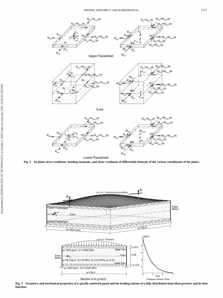
Lower FacesheetFig. 2 In-plane stress resultants, bending moments, and shear resultants of differential elements of the various constituents of the plates.
Upper Facesheet
Lower Facesheet
Pressure Versus Time
Fig. 3 Geometry and mechanical properties of a specific sandwich panel and the loading scheme of a fully distributed sinus blast pressure and its timefunction.
FROSTIG, RODCHEUY, AND KARDOMATEAS 1217
Dow
nloa
ded
by G
EO
RG
IA I
NST
OF
TE
CH
NO
LO
GY
on
Oct
ober
3, 2
016
| http
://ar
c.ai
aa.o
rg |
DO
I: 1
0.25
14/1
.J05
3309
Numerical Study
The numerical study presents the blast response of a simplysupported, square sandwich plate when subjected to a fully andlocalized distributed blast load. The boundary conditions of the plateassume that the upper and the lower facesheets are simply supportedand that the vertical displacements of the edges of the core areprevented. These conditions are fulfilled through the use of a specialedge beam; see Fig. 3 for details. The panel considered is based on aspecific setup used in an experimental blast investigation of Gardneret al. [24], with somemodifications. In both cases, the results includedeformed shapes between 0.05 and 1ms every 0.1ms, displacements,stresses at interfaces and within the depth of the core, and stressresultants of the facesheets and core. In the first case, a comparisonwith the elasticity solution (see work by Kardomateas et al. [31]) ispresented.The square panel, a � b � 152.4 mm, consists of two facesheets
and a core. The facesheets are made of E-glass vinyl-ester laminatedcomposite with a quasi-isotropic layup, �0∕45∕90∕ − 45�s. It has adensity of 1800 kg∕m3, an equivalent modulus of elasticity of13,600 MPa, and a foam core. The core (A300) is a Corecell™ A-
series styrene acrylonitrile foam with a density of 58.5 kg∕m3, anelasticity modulus of 32 MPa, a Poisson ratio of 0.25, and a shearmodulus of 12.8 MPa. In the case of the full blast case, the coreproperties are different; see next.
Blast Pressure: Fully Distributed
The first case consists of a fully distributed sinusoidal pressure loadapplied at the upper facesheets only and equals qt � 5.1e−1.25t
sin�πx∕a� sin�πy∕b� MPa, where a and b are the length and width ofthe plates, respectively; and t is measured in milliseconds. For thegeometry, mechanical properties, and pressure distribution in spaceand time, see Fig. 3. Please notice that the blast load almost diminishesafter 3 ms. This case is used for comparisonwith the benchmark of theelasticity solution byKardomateas et al. [31]. It includes the deformedshapes at the firstmillisecond in Fig. 4; the values of the displacementsversus time at the facesheets and the core in Fig. 5; and the interfacialstresses at the face–core interfaces versus time in Fig. 6. Here, the dataof the elasticity solution consisted of the data of the facesheetsdescribed in the previous paragraph and the following data for the core:Ec � 32.0 MPa, Gc � 20.0 MPa, and the Poisson ratio of μxy �
t=0.5000000000e-1 t=0.1500000000
t=0.2500000000
t=0.4500000000
t=0.6500000000t=0.7500000000
t=0.8500000000 t=0.9500000000
t=0.5500000000
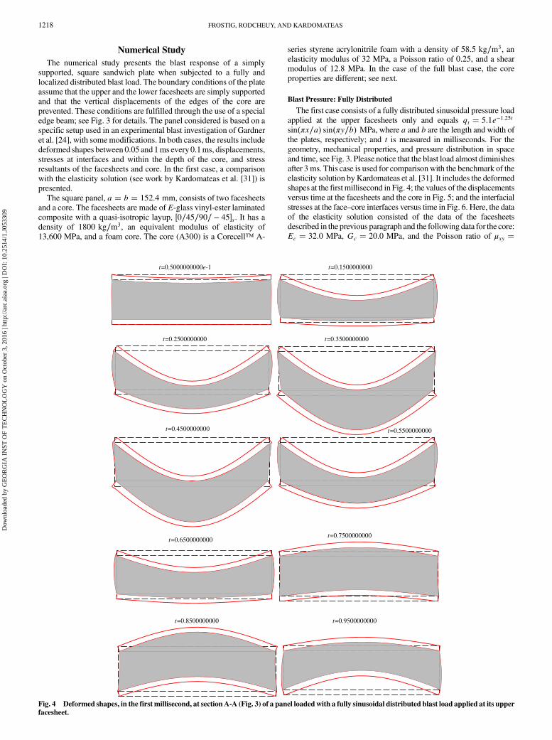
t=0.3500000000
Fig. 4 Deformed shapes, in the first millisecond, at sectionA-A (Fig. 3) of a panel loadedwith a fully sinusoidal distributed blast load applied at its upperfacesheet.
1218 FROSTIG, RODCHEUY, AND KARDOMATEAS
Dow
nloa
ded
by G
EO
RG
IA I
NST
OF
TE
CH
NO
LO
GY
on
Oct
ober
3, 2
016
| http
://ar
c.ai
aa.o
rg |
DO
I: 1
0.25
14/1
.J05
3309

0.25 and μxz � μyz � 0.35 for the facesheets and the core. The dataused here in the EHSAPT model include the same data as that of theelasticity but with μxy � μxz � μyz � 0.25 for the facesheets andμcxy � 0.25 and μcxz � μcyz � 0.35 for the core.The deformed shape of the sectionA-A (Fig. 3) that passes through
center of panel, at y � b∕2, appears in Fig. 4. It demonstratesqualitatively, but based on accurate numerical results, how the overallresponse of the panel evolves with time at the first millisecond andclarifies thewave propagation that occurs between the two facesheetslongitudinally as well as vertically. Initially, the upper loadedfacesheets move vertically, whereas the lower facesheet is still at rest.It is followed by large deformation of the upper facesheets but with asmall deformation in the lower facesheets, thus leading to asignificant reduction of the thickness of the core. In the next time step,t � 0.25 ms, the deformations of the lower facesheet increase,whereas those of the upper one do not change significantly. In thenext time steps, both facesheets almost move together with a smallextension in the core thickness. The response starts to changedirection at t � 0.55. Here, the lower facesheet moves upward butnot in tandem with the upper facesheet that still has significantvertical displacements; see t � 0.65 ms. Above that time step, thetwo facesheets move upward with unequal displacements. Pleasenotice that, during that time, the core height is changing from
contraction to expansion and the shape of its edge section changesfrom expansion to an S-type shape and to contraction. All thesepatterns are results of the waves that travel along the panel andthrough the core, in thevertical direction, between the two facesheets.The vertical displacement at midspan and the in-plane displace-
ments at the center of the support line at the x and y edges of thefacesheets and at the midheight of the core versus time appear inFig. 5. A very good correlation with the elasticity solution is ob-served. The displacements almost coincide at the first 1.5 ms, and thedifferences enlarge toward the end of the duration. These differencesare due to the numerical damping that occurs in the numerical inverseLaplace used for the elasticity solution; seeKardomateas et al. [31]. Itis similar to the damping that occurs when time difference methodssuch as theNewmarkmethod or others are used. Please notice that theEHSAPT is solved using the initial value DAE solvers of Maple [30]with an absolute and relative error of 10−7. Thevertical displacementsat midspan in Fig. 5a reveal that the displacements of the lowerfacesheets are larger at the initiation (about 0.25 ms) of the blast ascompared with the loaded facesheets; see the deformed shape att � 0.25 ms for clarification. It occurs as a result of the incidentwavethat travels from the loaded facesheets to the lower facesheet throughthe core. The vertical displacement of the core corresponds to anaverage of the displacements of the facesheets. In addition, notice that
u,v
[mm
]o
o
t
t
t t
t
t
t
t
b
b
bb
b
b
bb
EHSAPT
ELASTICITY
c
c
c
c
c
c
EHSAPT
EHSAPT
ELASTICITY
ELASTICITY
a) Vertical displacements at center of plate
b) In-Plane displacements, x and y dir., at center of support line
[ms]
[mm
]
[ms]
Fig. 5 Displacements versus time of the facesheets and core for a fully
distributed blast loading with comparison to the elasticity solution(Kardomateas et al. [31]) (solid line � EHSAPT, dashed line �elasticity).
xz,
yz[G
Pa]
zz[G
pa]
EHSAPT
EHSAPT
EHSAPT
ELASTICITY
ELASTICITY
ELASTICITY
Upper Interface Lower Interface
a) Shear stresses at center of edge support
b) Vertical normal stresses at center of plate
t
t
t
t
t
t
t
t
b
bb
bb
b
b
b
t [ms]
t [ms]
Fig. 6 Interfacial stresses versus time at face–core interfaces due to fullydistributed blast loading with comparison to elasticity (Kardomateaset al. [31]) (solid line � EHSAPT, dashed line � elasticity).
FROSTIG, RODCHEUY, AND KARDOMATEAS 1219
Dow
nloa
ded
by G
EO
RG
IA I
NST
OF
TE
CH
NO
LO
GY
on
Oct
ober
3, 2
016
| http
://ar
c.ai
aa.o
rg |
DO
I: 1
0.25
14/1
.J05
3309

Upper Facesheet
Lower Facesheet
t[ms]
Pressure Versus Time
Fig. 7 Geometry and mechanical properties of a specific panel loaded by localized blast distribution centered in the midst of the plate along with ameasured time function (C.L., center line).
t=0.5000000000e-1 t=0.1500000000
t=0.2500000000
t=0.4500000000
t=0.6500000000 t=0.7500000000
t=0.8500000000 t=0.9500000000
t=0.5500000000
t=0.3500000000
Fig. 8 Deformed shapes, in the first millisecond, at section A-A (Fig. 7) of a localized uniformly distributed blast load applied at the upper facesheet.
1220 FROSTIG, RODCHEUY, AND KARDOMATEAS
Dow
nloa
ded
by G
EO
RG
IA I
NST
OF
TE
CH
NO
LO
GY
on
Oct
ober
3, 2
016
| http
://ar
c.ai
aa.o
rg |
DO
I: 1
0.25
14/1
.J05
3309
the period of the transient response is about 1.7 ms. The in-planedisplacements of the facesheets and the midheight of the core in the xand y directions are identical; see Fig. 5b. Here, the in-planedisplacements of the facesheets coincide with the elasticity solution,and they are quite small as compared with those of the midheight ofthe core. The discrepancy between the EHSAPT and the elasticityincreases with time due to the numerical damping phenomenoninvolved in the elasticity solution. In addition, the magnitudes ofthese displacements, at the midheight of the core, are much largerthan those of the facesheets; and its time period is much smaller thanthat of the facesheets.The interfacial stresses versus time at the face–core interfaces at
the center of the plate and the center of support line in the x and ydirections appear in Fig. 6. Avery good correlation with the elasticitybenchmark is observed. The interfacial shear stresses, at the center ofthe support lines in the EHSAPT and the elasticity solution (seeFig. 6a), almost coincide through the first 3 ms with a time period ofabout 1.3 ms. Here, the interfacial shear stresses at the upper and thelower interfaces are in tandem, and they are almost identical exceptfor extreme values. The vertical normal stresses at the interfacesappear in Fig. 6b, and they reveal almost an erratic response, withvery short time periods much smaller than those of the adjacent shearstresses. The comparison is very satisfactory at the first milliseconds,and the differences enlarge with time due to the numerical dampinginvolved with the elasticity solution. Notice that the interfacialnormal stresses, at the upper and lower face–core interfaces, are intandem; and their extreme values are reached at the same time butwith different values.
In general, a very satisfactory comparison between the elasticityand the EHSAPT model is detected, especially at the first 1.5 ms.
Blast Pressure: Locally Distributed
This case investigates the blast response of a localized pressureload, located in the vicinity of center of the plate and uniformlydistributed at the upper facesheet, on a square area of 0.1a × 0.1bwith a blast pressure of 510e−1.25t MPa; see Fig. 7 for details. Thetransient dynamic response here has been solved using a Fourierseries description of the localized pressure with nine terms in eachdirection, which proved to converge. The results are described interms of deformed shapes at the first millisecond at various time stepsin addition to displacements, stress resultants of the facesheetsand core, interfacial shear and vertical normal stresses versus time,and for a specific time at y � b∕2 versus x, as well as distributionsof the displacements and stresses of the core through its depth atdifferent times.The deformed shapes of section A-A (Fig. 7) that passes through
center of the plate, at y � b∕2, at various time steps in the firstmillisecond appear in Fig. 8. At the initial time steps (t � 0.05 to0.95 ms), the localized load is associated with significant verticaldisplacements around the center of the plate, with almost nomovement of the lower facesheet. Hence, the initial response islocalized and is concentrated in the vicinity of the localized load,which is similar to a localized load on an elastic foundation.However,in the next time step (t � 0.25 to 0.35 ms), the panel starts to behaveas a sandwich plate where the two facesheets are moving downwardbut with unsmooth displacement patterns due to the localized loads
t
t
t
bb
bc
c
cc
u[m
m]
[mm
]
o
tb
xzyz
,[M
Pa]
t
b
zz[M
Pa]
b) Vertical displacements at center of plate
d) Interfacial vertical normal stresses at centerof plate
a) In-plane displacements in x directionat center of edge
c) Interfacial vertical shear stresses at centers ofedge supports
t [ms]
t [ms]
t [ms]
t [ms]
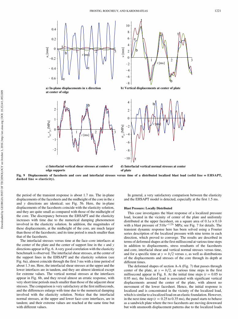
Fig. 9 Displacements of facesheets and core and interfacial stresses versus time of a distributed localized blast load (solid line � EHSAPT,dashed line � elasticity).
FROSTIG, RODCHEUY, AND KARDOMATEAS 1221
Dow
nloa
ded
by G
EO
RG
IA I
NST
OF
TE
CH
NO
LO
GY
on
Oct
ober
3, 2
016
| http
://ar
c.ai
aa.o
rg |
DO
I: 1
0.25
14/1
.J05
3309
(see deformed shape at t � 0.35 ms), and it is intensified att � 0.45 ms. The deformations change directions at t � 0.55 msand above, where the lower facesheets move upward, whereas theupper loaded facesheets are still downward. It almost returns to theresponse at the first time step at t � 0.75 ms, and both of themmoveupward above t � 0.85 ms. These shapes reveal that, in the firstmillisecond, the travelingwaves are amixture of in-plane and flexuralwaves in the facesheets, as well as in the vertical ones through thedepth of the core. Please notice that, due to the large displacements,themagnification factors of the drawing of the displacements here arehalf of that of the previous case.The displacements and the interfacial stresses versus time appear
in Fig. 9. The in-plane displacements, in x and y directions, at themidheight of the facesheets and the core at the center of the supportsappear in Fig. 9a. In general, the displacements are of the same orderas for the first case with the fully distributed pressure but with apressure load resultant that is almost one-quarter of that of first case. Italso reveals a very fast fluctuation for the core and a much slowerfluctuation for the facesheets. Here, the displacements of the core arealmost an order larger than those of the facesheets. Notice that thetrends here are similar to those of the fully distributed blast; seeFig. 5b. The vertical displacements at the center of the plate (seeFig. 9b) and are of an order larger than the in-plane ones but withmuch larger time periods similar to those of the first case (see Fig. 5a).Here, the curves are with local fluctuation, although the extremevalues are of similar order and at the same times as comparedwith theprevious case. Similar trends, but with local fluctuation as comparedwith the fully distributed case (see Fig. 6), occur for the shearinterfacial stresses at the panel supports (see Fig. 9c) and the verticalnormal interfacial stresses at the center of the plate (see Fig. 9d). Also,here, the time periods of the vertical normal stresses aremuch smallerthan those of the shear stresses.
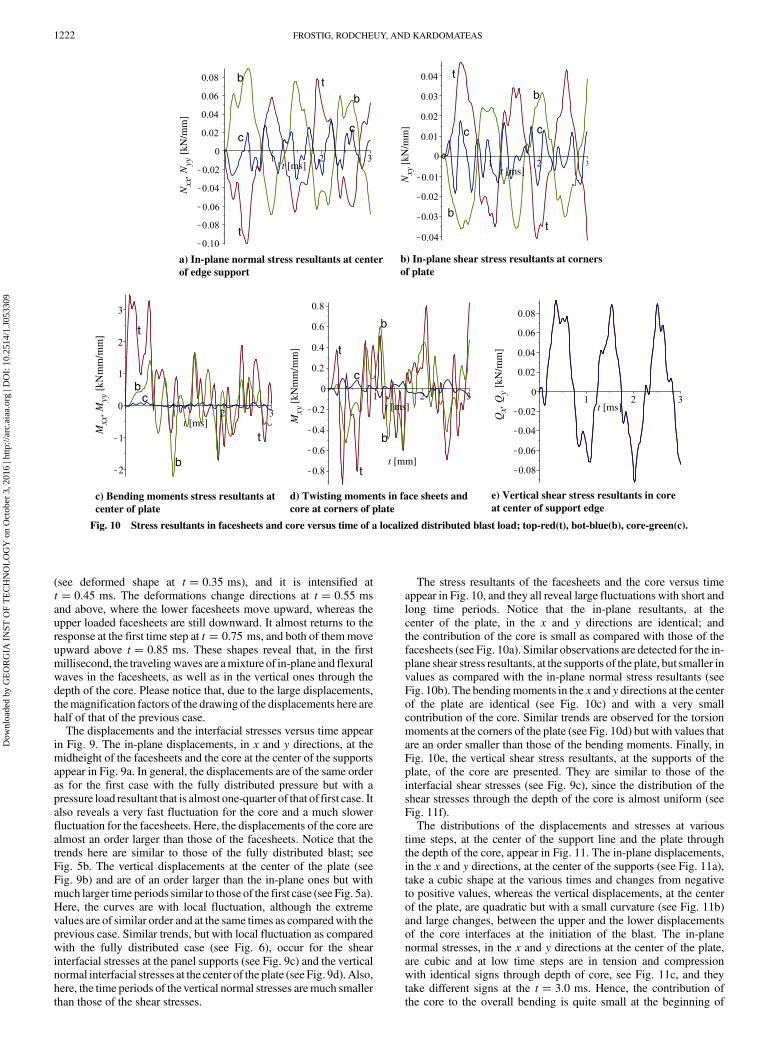
The stress resultants of the facesheets and the core versus timeappear in Fig. 10, and they all reveal large fluctuations with short andlong time periods. Notice that the in-plane resultants, at thecenter of the plate, in the x and y directions are identical; andthe contribution of the core is small as compared with those of thefacesheets (see Fig. 10a). Similar observations are detected for the in-plane shear stress resultants, at the supports of the plate, but smaller invalues as compared with the in-plane normal stress resultants (seeFig. 10b). The bendingmoments in the x and y directions at the centerof the plate are identical (see Fig. 10c) and with a very smallcontribution of the core. Similar trends are observed for the torsionmoments at the corners of the plate (see Fig. 10d) but with values thatare an order smaller than those of the bending moments. Finally, inFig. 10e, the vertical shear stress resultants, at the supports of theplate, of the core are presented. They are similar to those of theinterfacial shear stresses (see Fig. 9c), since the distribution of theshear stresses through the depth of the core is almost uniform (seeFig. 11f).The distributions of the displacements and stresses at various
time steps, at the center of the support line and the plate throughthe depth of the core, appear in Fig. 11. The in-plane displacements,in the x and y directions, at the center of the supports (see Fig. 11a),take a cubic shape at the various times and changes from negativeto positive values, whereas the vertical displacements, at the centerof the plate, are quadratic but with a small curvature (see Fig. 11b)and large changes, between the upper and the lower displacementsof the core interfaces at the initiation of the blast. The in-planenormal stresses, in the x and y directions at the center of the plate,are cubic and at low time steps are in tension and compressionwith identical signs through depth of core, see Fig. 11c, and theytake different signs at the t � 3.0 ms. Hence, the contribution ofthe core to the overall bending is quite small at the beginning of
N, N
[kN
/mm
]
t [ms] t [ms]
t [ms]
t [ms] t [ms]
t [mm]
xxyy
t
tt
t
b
b
bb
c c cc
N[k
N/m
m]
xy
M, M
[kN
mm
/mm
]xx
yy
t
t
t
t
b
b
b
b
c
c
M[k
Nm
m/m
m]
xy Q, Q
[kN
/mm
]x
y
a) In-plane normal stress resultants at centerof edge support
b) In-plane shear stress resultants at cornersof plate
c) Bending moments stress resultants atcenter of plate
d) Twisting moments in face sheets andcore at corners of plate
e) Vertical shear stress resultants in coreat center of support edge
Fig. 10 Stress resultants in facesheets and core versus time of a localized distributed blast load; top-red(t), bot-blue(b), core-green(c).
1222 FROSTIG, RODCHEUY, AND KARDOMATEAS
Dow
nloa
ded
by G
EO
RG
IA I
NST
OF
TE
CH
NO
LO
GY
on
Oct
ober
3, 2
016
| http
://ar
c.ai
aa.o
rg |
DO
I: 1
0.25
14/1
.J05
3309
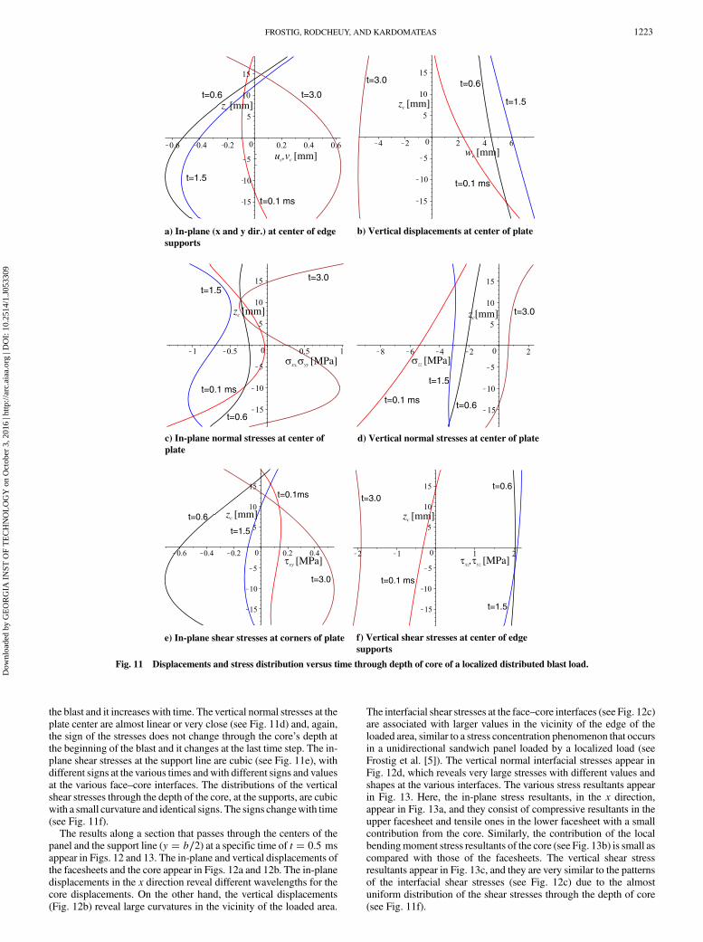
the blast and it increases with time. The vertical normal stresses at theplate center are almost linear or very close (see Fig. 11d) and, again,the sign of the stresses does not change through the core’s depth atthe beginning of the blast and it changes at the last time step. The in-plane shear stresses at the support line are cubic (see Fig. 11e), withdifferent signs at the various times andwith different signs and valuesat the various face–core interfaces. The distributions of the verticalshear stresses through the depth of the core, at the supports, are cubicwith a small curvature and identical signs. The signs changewith time(see Fig. 11f).The results along a section that passes through the centers of the
panel and the support line (y � b∕2) at a specific time of t � 0.5 msappear in Figs. 12 and 13. The in-plane and vertical displacements ofthe facesheets and the core appear in Figs. 12a and 12b. The in-planedisplacements in the x direction reveal different wavelengths for thecore displacements. On the other hand, the vertical displacements(Fig. 12b) reveal large curvatures in the vicinity of the loaded area.
The interfacial shear stresses at the face–core interfaces (see Fig. 12c)are associated with larger values in the vicinity of the edge of theloaded area, similar to a stress concentration phenomenon that occursin a unidirectional sandwich panel loaded by a localized load (seeFrostig et al. [5]). The vertical normal interfacial stresses appear inFig. 12d, which reveals very large stresses with different values andshapes at the various interfaces. The various stress resultants appearin Fig. 13. Here, the in-plane stress resultants, in the x direction,appear in Fig. 13a, and they consist of compressive resultants in theupper facesheet and tensile ones in the lower facesheet with a smallcontribution from the core. Similarly, the contribution of the localbendingmoment stress resultants of the core (see Fig. 13b) is small ascompared with those of the facesheets. The vertical shear stressresultants appear in Fig. 13c, and they are very similar to the patternsof the interfacial shear stresses (see Fig. 12c) due to the almostuniform distribution of the shear stresses through the depth of core(see Fig. 11f).
z [mm]c
z [mm]c
z [mm]c z [mm]c
z [mm]c
z [mm]c
t=3.0
t=3.0
u ,v [mm]c c
t=0.1 ms
t=0.1 ms
t=0.6t=0.6
t=1.5
t=1.5
w [mm]c
t=3.0
t=3.0
t=3.0
t=3.0
t=0.1 ms
t=0.1ms
t=0.1 ms
t=0.1 ms
t=1.5
t=1.5
t=1.5
t=1.5
t=0.6
t=0.6
t=0.6
t=0.6
xx, yy [MPa] zz [MPa]
xy [MPa] xz yz, [MPa]
a) In-plane (x and y dir.) at center of edgesupports
b) Vertical displacements at center of plate
c) In-plane normal stresses at center ofplate
d) Vertical normal stresses at center of plate
e) In-plane shear stresses at corners of plate f) Vertical shear stresses at center of edgesupports
Fig. 11 Displacements and stress distribution versus time through depth of core of a localized distributed blast load.
FROSTIG, RODCHEUY, AND KARDOMATEAS 1223
Dow
nloa
ded
by G
EO
RG
IA I
NST
OF
TE
CH
NO
LO
GY
on
Oct
ober
3, 2
016
| http
://ar
c.ai
aa.o
rg |
DO
I: 1
0.25
14/1
.J05
3309

Conclusions
A rigorous systematic analysis of the dynamic response of a sand-wich plate with a compressible compliant core using the extendedhigh-order sandwich panel theory is presented. In addition, a numer-ical study is conducted for a fully and locally distributed blast for aspecific configuration. The mathematical formulation is based onHamilton’s principle with kinematic relations of small deformationsand elastically linear materials. Notice that the equations of motion in
general are valid for any type of layout of the sandwich panel and anycombination of boundary conditions. In addition, it includes the high-order effects of the core along with its in-plane rigidity, in the x and ydirections, throughpresummed cubic and quadratic distributions of thedisplacements with unknown functions. The proposed computationalmodel provides a full detailed response in space and time of thevariousconstituents of the panel.The mathematical formulation uses Lagrange multipliers to
enforce compatibility at the upper and the lower face–core interfaces,in the three directions. It includes derivation of the equations ofmotion along with the definition of the appropriate boundary con-ditions using ordinary stress resultants for the facesheets and high-order ones for the core as a result of the presumed cubic and quadraticdistributions of the displacements.The benchmark solution is a closed-form solution of the elasticity
model for the case of an isotropic or orthotropic simply supportedsandwich panel. The governing equations of motion are presentedfor the isotropic facesheets and core. They consist of a mixed set ofpartially differential equations and algebraic ones.The numerical study investigates a simply supported sandwich plate
with a particular setup, used for blast experiments at the University ofRhode Island (seework by Gardner et al. [24]) and subjected to a blastloading, but with somemodifications. The numerical solution replacesthe external loading with a Fourier series and uses the appropriatetrigonometric functions to replace the partially differential equationswith a set of ordinary differential equations and algebraic ones. Thenumerical solution is achieved using a Maple built-in DAEs solver.Two types of blast loads are considered: a fully distributed sinuspressure used for comparison with the elasticity benchmark solution,and a partially distributed blast on a small square area in the vicinity ofthe center of the plate.The results, in general, include structural quantities such as dis-
placements, stresses, and stress resultants, at specific locations, versustime and the deformed shapes of a section that passes through thecenter of the support line and the center of the plate, at the firstmillisecond at various time steps. The deformed shapes of theEHSAPTmodel, for the two cases, explain qualitatively yet accuratelythe complicated transient dynamic repose and the wave propagationinvolved.In the first case, a very good correlation between the EHSAPTand
the elasticity solution throughout the duration time of the investiga-tion is observed. Up to 2 ms, a very good comparison is detectedand it deteriorates with time due to the numerical damping that thenumerical inverse Laplace method used in the elasticity solutionssuffers from; see Kardomateas et al. [31]. The results reveal that thevertical and the in-plane displacements of the facesheets havedifferent time periods than in the core. The in-plane displacements, inthe x and y directions, of the core and its vertical normal interfacialstresses follow smaller time periods.The second case demonstrates the effects of a localized blast load
on the response. Here, the uniform distribution of the load has beenreplaced by a Fourier series using nine terms in each direction. Theresponse in general follows the trends observed in the first case, but itsstress patterns are erratic with small time periods and the contributionof the core relative to that of the facesheets is small. The variousstress distributions, through depth of core, significantly change theirshapeswith time, from almost linear to nonlinear. The displacements,stresses, and stress resultants in a section that passes through thecenters of the plates and the line supports reveal smooth curveswith astress concentration in the center of the plate vicinity and near theedges of the loaded region.Finally, the paper reveals that the EHSAPT is accurate, mathemat-
ically robust, efficient, and expandable to include various sandwichpanel setups; any type or combination of boundary conditions;and any type of loading schemes (dynamic, blast or static, fullyloaded, or localized). In addition, due to the accurate robust solutionand its ability to determine any structural quantity at any point andat any time, the physical insight is significantly enhanced. Thus, theEHSAPT should be used for the analysis of very complex responsessuch as the transient dynamic response of a general sandwich panelwith a compliant core.
t
tb
b
c
c
N, N
[kN
/mm
]xx
yy
M, M
[kN
mm
/mm
]xx
yy
Q, Q
[kN
/mm
]x
y
a) In-plane stress resultants b) Bending moments stressresultants
c) Core vertical shear stress resultants
x [mm]
x [mm]
x [mm]
Fig. 13 Stress resultants in facesheets and core along sectionA-A (Fig. 7)of a distributed localized blast load at t � 0.5.
t
t
t
t
b
b
b
bc c
u[m
m]
x [mm]
x [mm]
x [mm]
w [
mm
]
x [mm]
o
b) Vertical displacementsa) In-plane displacements
xzyz
,[M
Pa]
c) Interfacial shear stresses
zz[M
Pa]
d) Interfacial vertical normalstresses
Fig. 12 Displacements of facesheets and core and interfacial stressesalong section A-A (Fig. 7) of a distributed localized blast load at t � 0.5.
1224 FROSTIG, RODCHEUY, AND KARDOMATEAS
Dow
nloa
ded
by G
EO
RG
IA I
NST
OF
TE
CH
NO
LO
GY
on
Oct
ober
3, 2
016
| http
://ar
c.ai
aa.o
rg |
DO
I: 1
0.25
14/1
.J05
3309

Acknowledgments
The research has been supported by the Office of Naval Research(ONR), grant N00014-11-1-0597; and the Ashtrom EngineeringCompany, which supports the professorship chair of Y. Frostig.The ONR Grant Monitor was Y. D. S. Rajapakse. His interest,encouragements, and the financial support received are gratefullyacknowledged.
References
[1] Allen, H. G., Analysis and Design of Structural Sandwich Panels,Pergamon, London, 1969.
[2] Plantema, F. J., Sandwich Construction, Wiley, New York, 1966.[3] Zenkert, D., An Introduction to Sandwich Construction, Chameleon
Press, London, 1995.[4] Vinson, J. R., The Behavior of Sandwich Structures of Isotropic and
Composite Materials, Technomic, Lancaster, 1999.[5] Frostig, Y., Baruch, M., Vilnai, O., and Sheinman, I., “High-Order
Theory for Sandwich-Beam Bending with Transversely FlexibleCore,” Journal of Engineering Mechanics, Vol. 118, No. 5, May 1992,pp. 1026–1043.doi:10.1061/(ASCE)0733-9399(1992)118:5(1026)
[6] Carrera, E., and Brischetto, S., “A Survey With Numerical Assessmentof Classical and Refined Theories for the Analysis of Sandwich Plates,”Applied Mechanics Reviews, Vol. 62, No. 1, 2008, Paper 010803.doi:10.1115/1.3013824
[7] Pagano, N. J., “Exact Solutions for Rectangular Bidirectional Com-posites and Sandwich Plates,” Journal of Composite Materials, Vol. 4,No. 1, Jan. 1970, pp. 20–34.
[8] Pagano, N. J., and Hatfield, S. J., “Elastic Behavior of MultilayeredBidirectional Composites,” AIAA Journal, Vol. 10, No. 7, 1972,pp. 931–933.doi:10.2514/3.50249
[9] Zenkour, A. M., “Three-Dimensional Elasticity Solution for UniformlyLoaded Cross-Ply Laminates and Sandwich Plates,” Journal of
Sandwich Structures and Materials, Vol. 9, No. 3, May 2007, pp. 213–238.doi:10.1177/1099636207065675
[10] Kardomateas, G. A., “Three Dimensional Elasticity Solution for Sand-wich Plates with Orthotropic Phases: the Positive Discriminant Case,”Journal of Applied Mechanics, Vol. 76, No. 1, 2009, Paper 014505.doi:10.1115/1.2966174
[11] Kardomateas, G. A., “An Elasticity Solution for the Global Buckling ofSandwich Beams/Wide Panels with Orthotropic Phases,” Journal of
Applied Mechanics, Vol. 77, No. 2, 2010, Paper 021015.doi:10.1115/1.3173758
[12] Kardomateas, G. A., and Phan, C. N., “Three-Dimensional ElasticitySolution for Sandwich Beams/Wide Plates with Orthotropic Phases:The Negative Discriminant Case,” Journal of Sandwich Structures andMaterials, Vol. 13, No. 6, 2011, pp. 641–661.doi:10.1177/1099636211419127
[13] Srinivas, S., and Rao, A. K., “Bending, Vibration and Buckling ofSimply Supported Thick Orthotropic Rectangular Plates and Lami-nates,” International Journal of Solids and Structures, Vol. 6, No. 11,1970, pp. 1463–1481.doi:10.1016/0020-7683(70)90076-4
[14] Librescu, L., Sang-YongOh, S.-Y., andHohe, J., “DynamicResponse ofAnisotropic Sandwich Flat Panels to Underwater and In-Air Explo-sions,” International Journal of Solids and Structures, Vol. 43, No. 13,2006, pp. 3794–3816.doi:10.1016/j.ijsolstr.2005.03.052
[15] Frostig, Y., and Baruch, M., “Free Vibration of Sandwich Beams with aTransversely Flexible Core: AHighOrder Approach,” Journal of Soundand Vibration, Vol. 176, No. 2, 1964, pp. 195–208.doi:10.1006/jsvi.1994.1368
[16] Sokolinsky, V., and Frostig, Y., “High-Order Buckling of Debonded(Delaminated) Sandwich Panels with a ‘Soft’ Core,” AIAA Journal,Vol. 38, No. 11, Nov. 2000, pp. 2147–2159.doi:10.2514/2.878
[17] Frostig, Y., and Thomsen, O. T., “High-Order Free Vibration of Sand-wich Panels with a Flexible Core,” International Journal of Solids andStructures, Vol. 41, Nos. 5, 6, March 2004, pp. 1697–1724.doi:10.1016/j.ijsolstr.2003.09.051
[18] Swanson, S. R., andKim, J., “Comparison of a Higher Order Theory forSandwichBeamswith Finite Element and Elasticity Analyses,” Journalof Sandwich Structures and Materials, Vol. 2, No. 1, 2000, pp. 33–49.doi:10.1177/109963620000200102
[19] Santiuste, C., Thomsen, O. T., and Frostig, Y., “Thermo-MechanicalLoad Interactions in Foam Cored Axi-Symmetric Sandwich CircularPlates–High-Order and FE Models” Composite Structures, Vol. 93,No. 2, 2011, pp. 369–376.doi:10.1016/j.compstruct.2010.09.005
[20] Frostig, Y., “On Wrinkling of a Sandwich Panel with a CompliantCore and Self-Equilibrated Loads,” Journal of Sandwich Structures andMaterials, Vol. 13, No. 6, Nov. 2011, pp. 663–679.doi:10.1177/1099636211419131
[21] Phan,C.N., Frostig,Y., andKardomateas,G.A., “Analysis of SandwichPanels with a Compliant Core and with In-Plane Rigidity–ExtendedHigh-Order Sandwich Panel Theory Versus Elasticity,” Journal of
Applied Mechanics, Vol. 79, No. 4, July 2012, Paper 041001.[22] Frostig, Y., Phan, C. N., and Kardomateas, G. A., “Free Vibration of
Unidirectional Sandwich Panels Part I: Elasticity and High-Order Com-putational Models,” Journal of Sandwich Structures and Materials,Vol. 15, No. 4, July 2013, pp. 377–411.doi:10.1177/1099636213485518
[23] Phan, C. N., Frostig, Y., and Kardomateas, G. A., “Free Vibration ofUnidirectional Sandwich Panels, Part II: Incompressible Core Modelsand Numerical Comparisons,” Journal of Sandwich Structures and
Materials, Vol. 15, No. 4, July 2013, pp. 412–428.doi:10.1177/1099636213485520
[24] Gardner, N.,Wang, E., Kumar, P., and Shukla, A., “BlastMitigation in aSandwich Composite Using Graded Core and Polyurea Interlayer,”Experimental Mechanics, Vol. 52, No. 2, 2012, pp. 119–133.doi:10.1007/s11340-011-9517-9
[25] Dvorak, G. J., Bahei-El-Din, Y. A., and Suvorov, A. P., “Impact, andBlast Resistance of Sandwich Plates” Major Accomplishments in
Composite Materials and Sandwich Structures: An Anthology of ONR
Sponsored Research, edited by Daniel, I. M., Goloutos, E. E., andRajapakse, Y. D. S., Springer Science and Business Media B.V., NewYork, 2009, pp. 625–659.
[26] Latourte, F., Gregoire, D., Zenkert, D., Wei, X., and Espinosa, H. D.,“Failure Mechanisms in Composite Panels Subjected to UnderwaterImpulsive Loads,” Journal of the Mechanics and Physics of Solids,Vol. 59, No. 8, 2011, pp. 1623–1646.doi:10.1016/j.jmps.2011.04.013
[27] Hoo Fatt, M. S., and Palla, L., “Analytical Modeling of CompositeSandwich Panels Under Blast Loads,” Journal of Sandwich Structuresand Materials, Vol. 11, No. 4, 2009, pp. 357–380.doi:10.1177/1099636209104515
[28] Li, R. F., Kardomateas, G. A., and Simitses, G. J., “Point-Wise Impulse(Blast) Response of a Composite Sandwich Plate Including CoreCompressibility Effects,” International Journal of Solids and Struc-
tures, Special Issue in Honor of Professor Liviu Librescu, Vol. 46,No. 10, 2009, pp. 2216–2223.doi:10.1016/j.ijsolstr.2009.01.036
[29] Mayercsik, N. P., “Finite Element Analysis of Advanced CompositeSandwich Panel Core Geometries for Blast Mitigation,” B.C.E. Thesis,Civil and Environmental Engineering, Univ. of Delaware, Newark, DE,2010.
[30] Char, B.W., Gedddes, K. O., Gonnet, G. H., Leong, B. L.,Monagan,M.B., and Watt, S. M., Maple V Library Reference Manual, Springer–Verlag, New York, 1991.
[31] Kardomateas, G. A., Rodcheuy, N., and Frostig, Y., “Transient BlastResponse of Sandwich Plates by Dynamic Elasticity,” AIAA Journal
[online], Jan. 2015.doi:10.2514/1.J052865
S. PellegrinoAssociate Editor
FROSTIG, RODCHEUY, AND KARDOMATEAS 1225
Dow
nloa
ded
by G
EO
RG
IA I
NST
OF
TE
CH
NO
LO
GY
on
Oct
ober
3, 2
016
| http
://ar
c.ai
aa.o
rg |
DO
I: 1
0.25
14/1
.J05
3309